

Page 1
firmware
defects.
hardware
If
HP
is
unable,
condition
return
to
which
HP
does
shall
as
warranted,
HP.
do
not
execute
not
warrant
be
uninterrupted
their
that
or
the
within a reasonable
Buyer
shall
programming
operation
error
free.
time,
to
repair
be
entitled
instructions
of
the
software,
or
replace
to a refund
of
any
the
due
to
such
firmware,
product
purchase
or
to
upon
a
CAUTION
Limitation
The
foregoing
1.
Improper
2.Buyer-supplied
3.
Unauthorized
4.
Operation
5.
Improper
THE
WARRANTY
WARRANTY,
SPECIFICALLY
of
warranty
or
inadequate
outside
site
WHETHER
DISCLAIMS
MERCHANTABILITY
Use
of
accessories
compromise
Nellcor
product
is a registered
Warranty
shall
maintenance
interfacing,
modification
of
the
environmental
preparation
SET
FORTH
WRITTEN
THE
AND
FITNESS
other
than
performance.
trademark
not
apply
or
misuse,
and
maintenance.
ABOVE
OR
IMPLIED
those
recommended
of
Nellcor,
to
defects
by
IS
EXCLUSIVE
ORAL,
resulting
Buyer,
specifications
AND
IS
EXPRESSED
WARRANTIES
FOR A PARTICULAR
by
Hewlett-Packard
Inc.
from:
for
the
product,
NO
OTHER
OR
OF
PURPOSE.
or
IMPLIED.
may
HP
©
Copyright
Hewlett-Packard
Company
1992, 1993,
1994,
1996
iii
Page 2
Printing
August
October
February
November
August
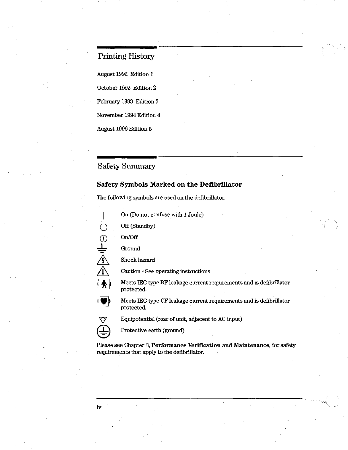
Safety
Safety
The
1992
1992
1993
1996
Summary
Symbols
following
On
—
Off
o
On/Off
History
Edition
Edition
Edition
1994
Edition
Edition
symbols
(Do
not
(Standby)
1
2
3
4
5
Marked
are
used
confuse
on the
on
with 1 Joule)
Defibrillator
the
defibrillator.
Ground
Shock
Caution - See
Sito
~
Meets
protected.
>
Meets
protected.
[e
Equipotential
<+
Protective
©
Please
‘requirements
iv
see
Chapter
hazard
IEC
IEC
that
operating
type
type
(rear
earth
3,
Performance
apply
to
instructions
BF
leakage
CF
leakage
of
unit,
(ground)
the
defibrillator.
current
current
-
adjacent
Verification
requirements
requirements
to
AC
input)
and
and
is
defibrillator
and
is
defibrillator
Maintenance,
for
safety
Page 3
WARNING
CAUTION
—
——
NOTE
—
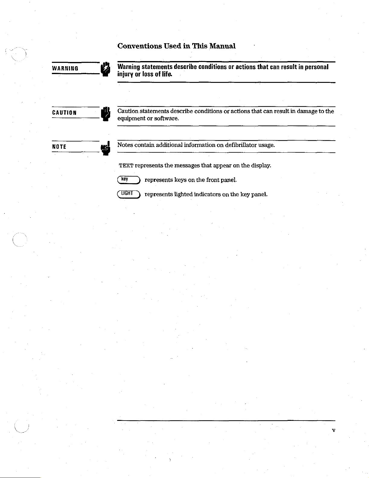
Conventions
v
Warning
injury
Y
Caution
eguipment
Notes
TEXT
Used
statements
or
loss
of
life.
statements
or
software,
contain
represents
additional
the
in
This
describe
describe
messages
conditions
information
Manual
conditions
that
or
or
actions
on
defibrillator
appear
on
actions
the
that
can
that
can
usage.
display.
result
result
in
personal
in
damage
to
the
key
represents
represents
keys
on
lighted
the
front
indicators
panel.
on
the
key
panel.
Page 4
Preface
This
manual
XL+
and
apply
to
This
manual
contains
XL
Defibrillator/Monitor.
both
models
is
organized
service
unless
as
information
The
otherwise
follows:
for
the
information
specified.
Hewlett-Packard
and
procedures
CodeMaster
in
this
manual
Chapter
lists
Chapter
installation
requirements.
Chapter
check
procedures
Chapter
tor
Chapter
service
Chapter
and
Chapter
parts,
Appendix
assigned
1—Introduction.
of
technical
2—Installation
and
3—Performance
the
defibrillator's
and
4—Theory
works
and
5—Troubleshooting.
person
6—Removal
replacing
7—Parts
and
provides
A—Connector
to
the
specifications,
explains
safety
describes
in
localizing
each
how
performance
requirements
of
Operation.
the
and
of
the
defibrillator's
Lists.
assembly
subassembly
Contains a general
and
lists
of
and
Configuration.
to
configure
Verification
operation
Contains
faults
to a replaceable
Replacement.
Lists
part
drawings.
Pin
Assignments.
and
using
that
apply
Provides
of
the
procedures
major
numbers
interconnections.
description
options
the
built-in
Contains
and
Summarizes
defibrillator
Maintenance.
tests,
to
the
an
overview
major
subassemblies.
subassembly.
subassemblies.
for
the
Identifies
of
the
defibrillators,
accessories.
the
defibrillator
for
specific
Explains
and
lists
maintenance
defibrillator.
of
how
the
and
error
codes
procedures
defibrillator's
and
for
replaceable
defines
customer
how
to
defibrilla-
to
aid the
removing
the
signals
Index.
Page 5
Contents
Introduction
The
CodeMaster
MTRO-00836L
Cart
XL+
1-2
and
XL
Defibrillator/Monitor
1-1
Inquiries
1-3
Specification
Options
CodeMaster
Country
Pacer
SpO»
Paddles
ECG
Hardware
Sync
Documentation
Standard
Cart
and
Accessories
XL+.and
Options.
Option—CodeMaster
Option
and
Cable/Connector
Options
Cable
Options
Accessories
1-14
Installation
Introduction
Installation
Line
Voltage
Installing
Loading
Connecting
Defibrillator
ECG
SpO,
Settings
and
Charging
the
Recorder
Paddles,
Input
Connector
Connector
Data
1-3
XL
Defibrillator/Monitor
1-8
1-12
Pad Options
Options
1-13
1-13
Options
Supplied
and
Configuration
2-1
2-1
2-2
the
Paper
Patient
Connector
2-17
1-8
XL+
1-12
1-14
Battery
2-6
Cables
2-8
2-14
only
1-13
1-14
2-2
and
1-12
SpO:
1-8
sensors
2-8
Configuration
Displaying
Displaying/Printing
Changing
Disabling
Shock
the
Configuration
Advisory
Performance
Introduction
Test
Intervals
Performance
Defibrillator
2-17
Setup/Diagnostic
Configuration
the
Internal
Algorithm
Verification
3-1
3-1
Verification
Calibration
Menu
Settings
Pace
Pulse
Measurement
Tests
3-2
2-18
Settings
2-23
Detection
Matrix
and
Maintenance
3-1
2-20
Marker
Print
2-25
(optional)
2-26
Contents-1
Page 6
Contents
Battery
Sync
Equipment
Performance
Visual
Delivered
Pacer
SpO,
SpO。
SpOz
HR
Alarm
ECG
Sync
Setup/Diagnostic
Defibrillator
Test
Calibrating
Defibrillator
Test
Testing
ECG
Test
Testing
PCI
CRT
Test
Testing
Recorder
Test
Testing
Controls
Indicator
Testing
Battery
Testing
Pacer
Test
Testing
Printing
Capacity
Cardioversion
List
Inspection
Energy
Test
3-5
Test
36
Internal
Functional
Test
Simulation
Cardioversion
Calibration
Prerequisites
the
Test
Prerequisites
the
Defibrillator
Monitor
Test
Prerequisites
the
ECG
Calibration
Test
3-21
Prerequisites
the
CRT
Test
Prerequisites
the
Recorder
Test
3-25
Test
the
Indicators
Capacity
the
Battery
Test
(Option—XL+
Prerequisites
the
Pacer
the
System
Test
3-3
Verification
3-4
Level
Self-Test
Test
3-6
3-7
Test
Menu
Defibrillator
3-14
3-18
3-18
3-21
3-21
3-23
3-26
Test
(Error)
3-2
Test with
Test
3-6
3-6
with
External
Tests
3-13
3-13
3-15
3-15
3-18
3-21
3-23
3-23
3-27
3-28
Capacity
Only)
3-30
3-30
Log
External
3-4
3-5
3-13
3-28
3-30
3-31
Monitor
Monitor
3-10
3-2
3-7
Preventive
Care
and
Cleaning
Cleaning
Steam
Contents-2
and
Sterilizing
Prevacuum
Maintenance
3-32
Sterilizing
Sterilization
the
Internal
the
3-32
Internal
Paddies
3-33
Paddles
3-33
3-33
Page 7

Flash
Gravity
Ethylene
Cleaning
Sterilization
Sterilization
Oxide
Sterilization
the
Printhead
3-33
3-34
and
3-34
Paper
Sensor
Contents
3-34
Safety
Tests
Defibrillator
Visual
Inspection
Performance
Charge
Pacer
SpOz
ECG
Setup/Diagnostic
Energy
3-37
338
Simulation
Cómments:
Theory
of
Introduction
Circuit
Control
Defibrillator
The
Digital
Power
Miscellaneous
Power-Up/Down
References
Board
Processor
Defibrillation
Charging
Discharging
System
Keyboard
Central
Display
Recorder
Interface
Digital
Power
Switch A Control
LED
OFF
Power-Up
Power-Down
Monitoring
Monitor
Processing
Signal
Supply
Backup
Failure
Drivers
State
and
Processor
Control
Control
to
3-36
Checklist
3-37
Tests
3-38
Operation
44
Processor
3-37
Level
3-38
Menu
4-1
4-1
4-2
Control
4-5
Indicator
4-7
4-7
the
Option
Interface
Supply
Detector
4-8
49
Analog
4-10
4-10
Functions
Processes
4-10
Functional
Functional
3-37
Tests
4-4
4-5
Interface
4-7
Slot
4-8
4-8
48
4-8
3-37
3-38
4-8
4-10
Group
4-6
Group
4-9
44
4-7
Power
Supply
4-11
Contents-3
Page 8

Contents
AC/DC
Battery
DC/DC
High
Battery
Safety
Patient
High
Patient
ECG
Power
Leads
Paddles
Cal
Data
Pre-Discharge
Paddles
CRT
Vertical
Horizontal
Video
Pacer
Power
Pulse
Pacer
Patient
Converter
Charger
Converter
Voltage
Connector
Relay
Relay
Voltage
Circuit
Front
Supplies
Input
Input
Pulse
Communication
in
Deflection
Deflection
4-22
Board
Supply
Control
Current
Isolation.
4-11
Control
4-12
Board
4-13
Drive
Charger ' 4-14
End
Protection
4-19
Pocket
Deflection
4-14
Drive
4-14
4-15
Board
4-18
Protection
Impedance
4-19
Board
‘4-22
4-23
4-23
4-23
4-24
4-24
4-12
4-13
4-17
4-19
4-19
4-19
4-19
4-20
4-22
SpO,
Board
Floating
Grounded
Contents-4
Section
Photo
Amplifier.
Excessive
Ambient
Amplification
Phase
Separation - Dark
Multiplexer
A/D
Converter
LED
Drivers
Section
Microprocessor
Communication
Power
Patient
Supply
Isolation
Light
Light
4-24
4-25
4-26
Detection
Rejection
426
4-27
4-27
4-27
4-28
System
4-28
4-28
4-28
4-26
4-26
Subtract
4-28
Filter
4-26
Page 9

Contents
Recorder
Keypanel
Interface
Boards
Defibrillator-Pacer
Standard
Internal
External
External
Paddles
Adhesive
Paddles
4-30
Pads
Troubleshooting
Introduction
Maintenance
Troubleshooting
Verify
the
Check
the
Using
the
Using
Setup/Diagnostic
Verification
Test
Equipment
Safety
The
Error
Considerations
System
Codes
Clearing
65-1
Philosophy - 5-1
Guide
Failure
Error
Troubleshooting
after
Log
5-6
the
Error
51.
(System)
Repair
5-3
5-4
Log
Board
4-29
Patient
4-30
430
5-1
Log
Tables
Tests
in
5-2
5-3
58
4-29
Connections
5-1
5-2
Troubleshooting
4-30
5-2
"
Troubleshooting
Testing
Removal
the
and
Power
Introduction
Tool
Requirements
Removing
Opening
Removing
Removing
Removing
Removing
Removing
Removing
the
the
Defibrillator
the
the
and
the
the
the
Tables
5-8
Supply
Replacement
6-1
6-2
Battery
Recorder
Recorder
Disassembling
Pacer
Pacer
Power
6-3
Chassis
6-6
Platen
Keypad
Board
Supply
5-19
6-4
Assembly
the
Keypanel
Assembly
6-11
Assembly
6-8
Assembly
6-10
6-12
6-9
Contents-5
Page 10

Contents
Removing
Removing
Removing
Removing
Removing
Removing
Adjusting
Adjusting
Replacing
Replacing
Replacing
Verifying
“Parts
Introduction
The
CodeMaster
Operation
Lists
the
the
the
the
the
the
the
CRT
the
Internal
the
Lithium
the
Power
the
Battery
Models
CRT
Assembly
Control
ECG
Front
High
Voltage
High
Voltage
Patient
6-30
Supply
After
7-1
and
Board
End
Board
Charger
Capacitor
Inductor
Delivered
Battery
Fuses
Fuse
7-1
6-39
Service
Sp0,
6-16
6-26
Energy
6-36
6-41
Board
6-19
and
Relay
6-24
Calibration
6-38
6-14
Assembly
6-33
6-21
Ordering
Calling
United
Canada
Cart
Connector
Control
Front
ECG
QRS
Defibrillator
Keypanel
Pacer
Contents-6
Information
for
Assistance
States
of
7-3
Parts
Volume
and
Board
End
Board
Out
Connector
Board
Keypanel
Pin
America
Control
Connector
7-2
7-3
7-3
Repair
Assignments
Connectors
7-32
A-17
Α-20
А-20
A-22
Board
A-23
A-3
A-20
|
Page 11

Contents
Pacer
Power
High
Patient
CRT
SpO。
Board
Supply
Voltage
Inductor
Deflection
Board
Recorder
Battery
Battery
HV
Capacitor
Patient
50-Ohm
ECG
In
AC
Line
Energy
A-23
Board
Board
A-28
Board
A-31
Interface
Board - A-32
Assembly
Relay
Load
Assembly
Connector
Module
Select
Board
A-33
A-33
A-34
Switch
A-24
A-26
А-28
A-32
A-33
A-34
A-34
A-34
Index
Contents-7
©
Page 12

List
Figure
Figure
Figure
Figure
Figure
Figure
Figure
Figure
Figure
Paddles
of
Figures
1-1.
CodeMaster
2-1.
Accessing
2-2.
Installing
2-3.
Loading
2-4.
External
2-5.
Pads
2-6.
Internal
2-7.
Opening
2-8.
Connecting
2-13
the
the
the
Paddle
Adapter
Paddles
Lock
XL+
Defibrillator/Monitor
Battery
Battery
Paper
Set
Cable
2-12
External
Compartment
2-4
2-7
2-8
and
External
2-10
Paddles,
Adhesive
1-2
2-3
Adhesive
Pads,
Pads
or
2-9
Internal
Figure
Figure
Figure
Figure
Figure
Figure
Figure
Figure
Figure
Figure
Figure
Figure
Figure
Figure
2-9.
An
ECG
Patient
2-10.
Connecting a Patient
2-11.
Connecting
2-12.
Setup/Diagnostic
2-13.
Configuration
2-14.
Configuration
3-1.
Sync
Cardioversion
3-2.
Setup/Diagnostic
3-3.
Calibrate
3-4.
Defibrillator
3-5.
ECG
3-6.
CRT
3-7.
Recorder
3-8.
Controls
Defibrillator
(Monitor)
Test:
Test
Test:
Test
Cable
an
SpO,
Default
Default
Menu
Test
Screen
Test
Pattern
Test
3-25
2-14
Cable
Sensor
Menu
Test
2-18
Settings
Settings—Setup
Setup
3-11
Screen
3-16
3-19
3-22
Pattern
2-16
2-17
—Setup
3-8
3-14
3-24
Menu 1 2-21
Menu 2 2-22
Figure
Figure
Contents-8
3-9.
Indicators
3-10.
Battery
Test
3-27
Capacity
Test
3-29
Page 13

List
of
Figures
Figure
Figure
Figure
Figure
Figure
Figure
Figure
Figure
Figure
Figure
Figure
Figure
Figure
Figure
3-11.
3-12.
4-1.
4-2.
4-3.
4-4.
4-5.
4-6.
4-7.
4-8.
4-9.
5-1.
6-1.
6-2.
Pacer
Cleaning
Control
Power
High
Patient
Damped
ECG
CRT
Pacer
Test
the
Board
Supply
Voltage
Circuit
Sinusoidal
Front
Assembly
End
Block
SpO, Board
System
Accessing
Opening
(Error)
the
the
3-30
Printhead
Block
Block
Board
Block
or
Diagram
Diagram
Block
Diagram
Diagram
Waveform
Block
Block
Diagram
Block
Log
Battery
Defibrillator
Diagram
Diagram
4-23
Diagram
Format
6-3
Paper
4-3
4-11
4-15
Parameters
4-20
4-25
5-4
Chassis
Sensor
4-13
4-18
6-4
3-35
4-16
Figure
Figure
Figure
Figure
Figure
Figure
Figure
Figure
Figure
Assembly
Figure
Figure
6-3.
Removing
6-4.
Configuring
6-5.
Removing
6-6.
Removing
6-7.
Removing
6-8.
Removing
6-9.
Removing
6-10.
Removing
6-11.
Removing
6-23
6-12.
Removing
6-13.
High
the
the
the
the
the
the
the
the
the
the
Voltage
Recorder
Keypanel
Pacer
Power
CRT
Control
Control
Connection
Assembly
ECG
High
High
Board
Supply
Board
Board
Front
Voltage
Voltage
6-7
Circuit
6-11
Board.
6-15
Cables
6-18
End
Board
Charger
Capacitor
Diagram
Board
6-13
and
and
(front
6-10
Connectors
6-20
Relay
6-25
view)
6-28
Contents-9
6-17
Page 14

List
of
Figures
Figure
Figure
Figure
Figure
Figure
Figure
Figure
Figure
Figure
Figure
Figure
Figure
Figure
Figure
6-14.
6-15.
6-16.
6-17.
6-18.
6-19.
6-20.
7-1.
7-2.
7-3.
7-4.
7-5.
7-6.
7-7.
High
Voltage
CRT
Adjustments
CRT
Test
R139
Potentiometer
Replacing
Replacing
Replacing
Top
Case
Top
Case—Inside
Bottom
Bottom
Battery
Key
Panel
High
Voltage
Pattern
the
the
the
Parts
Case
Case
Door
Assembly
Connection
6-31
6-32
Lithium
Power
Battery
List
7-4
7-8
79
|
7-10
Assembly
Assembly
Diagram
6-34
Battery
Supply
Fuse
7-14
7-15
7-19
6-37
Fuses
6-40
(schematic)
6-38
6-29
Figure
Figure
Figure
Figure
Figure
Figure
Figure
Figure
Contents-10
7-8.
7-9.
7-10.
7-11,
7-12,
7-12.
7-13.
A-1.
CRT
Assembly
Recorder
External
External
External
Assembly
Paddles
Paddles
Paddles
7-26
External
Paddles
Interconnect
7-20
7-22
Assembly—Apex
Assembly—Sternum,
Assembly—Sternum,
Connector
Block
Diagram
7-24
Assembly
A-2
with
PCI
without
7-29
PCI
7-25
7-26
Page 15

List
of
Figures
Contents-11
Page 16

List
Table
Table
Table
Table
Table
Table
Table
Table
Table
Numbers
Table
Numbers
Table
of
1-1.
1-2.
1-3.
1-4.
1-5.
1-6.
1-7.
1-8.
1-9.
1-10.
1-12.
Tables
Physical Specifications
Environmental
Electrical
Power
External
SpOs
Shock
Country
Codemaster
1-10
Codemaster
1-10
Power
and
Pacer
Monitor
Advisory
Option
Cord
Specifications
Specifications
Battery
XL+
Specifications
(Optional—XL+
(Optional)
(Optional)
Configurations
(M1722A/B)
XL
(M1723A/B)
Part
Numbers
1-3
1-4
1-4
only)
1-7
1-7
1-8
Documentation
Documentation
1-11
1-6
1-6
Part
Part
Table
visory
Table
Connector
Table
Table
Table
Table
Table
Table
“Table
Table
Table
Table
Table
1-11.
Documentation
2-1.
2-2.
2-3.
2-4.
2-5.
2-6.
3-1.
3-2.
3-3.
3-4.
4-1.
4-2.
CodeMaster XL/XL+
1-11
Paddles/Pads
2-11
Patient
Displaying/Printing a Configuration
Cables
Sets,
and
Changing a Configuration
Configuration
Configuration
Equipment
Settings—Setup
Settings—Setup
List
Performing a Setup/Diagnostic
Defibrillator
Controls
PADID
Specifications
Test
Test
Steps
Voltage
for
Value
(M1722A/B & M1723A/B)
Adapter
Lead
Cables
Sets
|
2-15
Setting
Menu 1 2-24
Menu 2 2-25
3-3
Test
Limits
Damped
3-26
vs.
Paddles
3-18
Type
Sinusoidal
for
Defibrillator
Setting
2-20
2-23
3-12
4-6
Output
Shock
Ad-
Waveforms
Table
Contents-12
4-3.
4-17
CRT
Specifications
4-21
Page 17

个
一
List
of
Tables
Table
Table
Table
Table
Table
Table
Table
Table
Table
Table
Table
Table
Table
Table
4-4.
5-1.
5-2.
5-3.
5-4.
5-5.
5-6.
5-7.
5-8.
5-9.
5-10.
5-11.
5-12.
5-13.
Control
Error
Audible
On-screen
On-screen
On-screen
SpO2
Printed
Operation
Power
Recorder
Display
Panel
Signal
Codes
Indicators
System
Defibrillator/Monitor
Pacer
Messages
Failure
Problems
Supply
Problems
and
Keys
Defibrillator
Specifications
5-6
5-9
Messages
Messages
(Option)
Messages
5-13
and Battery
5-15
Logic
5-16
5-17
Problems
5-17
4-21
5-10
Messages
(Option—-XL+
5-12
5-13
5-14
5-10
only)
5-12
Table
Table
Table
Table
Table
Table
Table
‘Table
Table
Table
Table
Table
5-14.
7-1.
7-2.
7-3.
7-4.
7-5.
7-6.
7-7.
7-8.
7-9.
7-10.
7-11.
Pacer
Top
Case
Top
Case—Inside
Bottom
Battery
Keypanel
High
Voltage
CRT
Assembly
Recorder
Paddle
Assembly
External
Supplies
Problems
Parts
List
Case
Parts
Door
Assembly
Assembly
Assembly
Parts
Assembly
Paddles
List
7-30
5-18
7-4
Parts
Parts
List
List
7-10
Parts
Parts
List
Parts
List
Parts
List
List
Connector
7-8
List
7-15
List
7-21
7-22
7-27
Assembly
7-14
7-19
Parts
List
Contents-13
7-29
Page 18

List
of
Tables
Table
Table
Table
Table
Table
Table
Table
Table
Table
Table
"
Table
©
Table
Table
A-1.
Control
A-2.
Control
A-3.
Control
A-4.
Control
A-5.
Control
A-6.
Control
A-7.
Control
A-8.
Control
A-9.
Control
A-10.
Control
A-11.
Control
A-13.
Control
A-14.
Control
Board
Board
Board
Board
Board
Board
Board
Board
Board
Connections
J1
J2
J3
J4
J5
J6
J7
J8
Board
Board
Board
Board
to
Pacer
to
Front
to
ECG
Out
to
QRS
Volume
to
Defibrillator
to
Keypanel
to
Pacer
to
Power
J9
to
High
J10
to
Patient
J12
to
SpO2
J13
to
Recorder
A-3
Keypanel
End
Board
Connector
Control
Connector
Board
Board
Supply
Ji
Voltage
Inductor
Board
Interface
Board
J2
Al
A-10
Board
Board
PL
A-14
J1
A-4
A-6
A-6
J1
A-8
J2B
J2
A-13
Board
A-3
A-7
A-10
A-12
J1
A-16
Table
Table
ECG)
Table
ECG)
Table
ECG)
Table
Table
Table
Table
Table
Contents-14
A-15.
A-16.
A-18
A-17.
A-18
A-18.
A-19
A-19.
A-20.
A-21.
A-22.
A-23.
Front
Front
Front
Front
Front
Defibrillator
Keypanel
Keypanel
Keypanel
End
Board
End
Board
End Board
End
Board
End
Board
Connector
Board
Board
Board
Connections
J1
to
ECG
In
J1
to
ECG
In
|
J1
to
ECG
In
J61,
J62, J63, J65,
J1
A-20
Connections
32
to
Energy
J3
to
SpOz
Board
A-17
Connector
、
Connector
Connector
J66
A-22
Select
Switch
P2
A-23
(8-pin
(6-pin
(12-pin
A-19
A-22
Page 19

List
of
Tables
Table
Table
Table
Table
Table
Table
Table
Table
Table
Table
‘
Table
Table
Table
Table
A-24.
A-25.
A-26.
A-27.
A-28.
A-29.
A-30.
A-31.
A-32.
A-33.
A-34.
A-35.
A-36.
A-37.
Pacer
Pacer
Power
Power
Power
High
High
High
Board
Board
Supply
Supply
Supply
Voltage
Voltage
Voltage
Patient
CRT
Deflection
CRT
Deflection
CRT
Deflection
CRT
Deflection
SpOz
Board
Connections
J51,
Board
J1
J2A
Board
Board
Board
Inductor
Board
Board
Board
Board
Connections
P51.
A-23
Connections
to
AC
Input
to
High
Voltage
Connections
J3,
J5,
J6,
to
Battery
A-28
Connections
J2
to
J3
to
J4
to
A-31
A-23
Cable
J8
Board
CRT
CRT
CRT
A-24
A-24
Board
JI
A-26
A-26
A-27
A-28
Deflection
Socket
Socket
Board
Board
A-25
Yoke
J5
J5
A-29
A-30
A-30
Table
Table
Table
Table
A-38.
A-39.
A-40.
A-41.
SpOz
Board
Battery
Battery
Patient
to
Board
Board
Relay
SpOz
Input
Connections
J4
to
Battery
A-33
Connector
A-32
Assembly
A-31
JI
A-32
Contents-15
Page 20

List
of
Tables
Contents-16
 Loading...