

Page 1

Cut Sheet Printers
Maintenance Manual
Models C30 and C30D
HP Part No. C4000-90006
Page 2

Notice
Hewlett-Packard makes no warranty of any kind with regard to this material, including,
but not limit ed to, the implied warranties of merchantabil ity and fitness for a particular
purpose. Hewlett-Packard shall not be liable for errors contained herein or for incidental
or consequential damages in connection with the furnishing, performance, or use of this
material.
Hewlett-Packard assumes no responsibility for the use or reliability of its software on
equipment that is not furnished by Hewlett-Packard.
This document contains proprietary information which is protected by copyright. All
rights are reserved. No part of this document may be photocopied, reproduced, or translated to another language without the prior written consent of Hewlett-Packard Company.
The information contained in this document is subject to change without notice.
Printing History
New editions are complete revisions of the manual. The dates on the title page change
only when a new edition is published.
The software code (EXXX) printed below the date indicates th e version level of the software product at the time of publication.
Edition 1 . . . . . . . . . . . . . . . . . . . . . . . . . . .March 1994
Edition 2. . . . . . . . . . . . . . . . . . . . . . . . . . .December 1994
Trademarks
PCL is a trademark of the Hewlett-Packard Company. CG Times, a product of Agfa Corporation, is based o n T imes New Roman, a regi stered tr ademark of Monotype Cor poratio n
PLC. ITC Zapf Dingbats is a U.S. registered trademark of International Typeface Corporation. PostScript is a registered trademark of Adobe Systems, Inc. in the U.S.A. and other
countries. Times Roman and Univers are trademarks of Linotype AG and its subsidiaries.
Centronics is a U.S. registered trademark of Centronics Corporation. PhoenixPage is a
trademark of Phoenix technologi es, Ltd. UNIX is a register ed trad emark of UNIX System
Laboratories Inc. in the U.S.A. and othe r countr ies. DE C LN03+ is a register ed trade mark
of Digital Equipment Corporation. All other trademarks are the properties of their respective owners.
-ii
Page 3

Warnings and Cautions
A WARNING denotes a hazard. It calls attention to a procedure or practice, which, if not
done correctly or adhered to, could result in personal injury. Do not proceed beyond a
WARNING sign until the indicated conditions are fully understood and met.
A CAUTION denotes a hazard. It calls attention to a procedure which, if done incorrectly
or inattentively, coul d damage or destroy pa rt or all of t he product. Do not proceed beyond
a CAUTION until the indicated conditions are fully understood and met.
Conventions
The following conventions are used throughout this manual:
Notes contain important information set off from the text.
Caution messages indicate procedures which, if not observed,
could result in damage to the equipment.
Note
Caution
Warning
Warning messages call attention to situations that could result
in personal injury.
-iii
Page 4

Preface
The C30/C30D Maintenance Manual contains all the information needed to maintain and
service Hewlett Packard C30 and C30D printers. The C30 printer series are high-speed,
non-impact printers utilizing electrophotographic imaging technology.
The information in this maintenance manual is for author ized field repr esentative s who are
familiar with bas ic pr inter opera ti ons. It serve s a s a supp leme nt to tr aining class es and pro vides a basis for discussion with regional field service engineers and customer support
representatives.
Using This Manual
This manual is organized into the following sections:
Chapter 1, “Printer and Troubleshooting Overview”
Reviews the organization of the manual, the way the printer works, and how to troubleshoot the printer, including some standard procedures to follow when troubleshooting.
This chapter also inclu des a char t d etail ing ex actly what each c auses e ach error code, i llus trations of all senso rs in the print er, and a list of abbre viati ons use d th roughou t the manual.
Chapter 2, “TAG Cross- Reference Tables”
Provides cross-refe re nce tables; look up specific p ri nter problem description ( in e it her the
mechanical malfunction, error code, or print quality description tables), then turn to the
TAG indicated on the chart to troubleshoot the problem.
Chapter 3, “Troubleshooting Analysis Guide (TAGs)”
Detailed step-by-s tep p rocedu res t o hel p you i solat e and reso lve s peci fic pr inter probl ems.
If you are not sure which TAG to start with, begin with the overview, TAG 001.
Chapter 4, “Print Quality Samples”
Shows print test patte rns in dicat ing spec ific proble ms, and refer encin g the TAG that treats
each problem.
Chapter 5, “Diagnostic Tests”
Reviews each printer software diagnostic.
Chapter 6, “Wiring Diagrams and Electrical Data”
Shows printer schematics and locations of individual components.
Chapter 7, “Removal/Replacement Procedures”
Outlines procedures to follow when removing and replacing printer parts, also called
FRUs (Field-Replaceable U nits).
-iv
Page 5

Chapter 8, “Options”
Provides information about the optional High Capacity Input and High Capacity Output
bins.
Chapter 9, “General Printer Maintenance”
Reviews printer maintenance procedures to complete during service calls.
Appendix A
Lists the abbreviations and acronyms used in the manual.
Index
Provides a list of references to topics and part numbers mentioned in the Maintenance
Manual
Other Manuals
The C-Series Illustrated Parts Catalog shows every FRU and CRU (customer-replaceable
unit) in the printer, including part number information. This information is frequently
updated.
The HP C30 and C30D Guide to Operations, C4000-96006, contains all the information
needed to operate Hewlett Packard C40D printers.
The HP C30 and C40D Paper Specifications Guide, C4672-90002, explains the various
kinds of papers usable in the printer, how to care for them, and how to minimize paperrelated problems with the C40D.
Copyright © 1995 Hewlett-Packard Company. All rights reserved. January 1995
Please address any comments or questions with respect to this document to:
Publication Dep artment
Hewlett-Packard Company
HP Printers - MS 44MC
System Peripherals Operation
19111 Pruneridge Avenue
Cupertino, CA 95014
-v
Page 6

-vi
Page 7

Contents
Printer and Troubleshooting Overview
Contents . . . . . . . . . . . . . . . . . . . . . . . . . . . . . . . . . . . . . . . . . . . . . . . . . . . . . . . . . .1-2
Theory of Operation . . . . . . . . . . . . . . . . . . . . . . . . . . . . . . . . . . . . . . . . . . . . . . . . .1-3
Paper Path and Cycle Sequence . . . . . . . . . . . . . . . . . . . . . . . . . . . . . . . . . . . . . . . .1-5
Simplex Printing. . . . . . . . . . . . . . . . . . . . . . . . . . . . . . . . . . . . . . . . . . . . . . . . . . . . . . . 1-5
Duplex Printing . . . . . . . . . . . . . . . . . . . . . . . . . . . . . . . . . . . . . . . . . . . . . . . . . . . . . . . 1-5
Error Code Technical Definitions. . . . . . . . . . . . . . . . . . . . . . . . . . . . . . . . . . . . . . .1-7
Sensor and Switch Locations . . . . . . . . . . . . . . . . . . . . . . . . . . . . . . . . . . . . . . . . .1-11
Troubleshooting Overview . . . . . . . . . . . . . . . . . . . . . . . . . . . . . . . . . . . . . . . . . . .1-15
General Troubleshooting Tips . . . . . . . . . . . . . . . . . . . . . . . . . . . . . . . . . . . . . . . . . . . 1-15
The Problem: Printer or Host? . . . . . . . . . . . . . . . . . . . . . . . . . . . . . . . . . . . . . . . . . . . 1-16
Protocol Converters . . . . . . . . . . . . . . . . . . . . . . . . . . . . . . . . . . . . . . . . . . . . . . . . . . . 1-17
Reading the Error Log . . . . . . . . . . . . . . . . . . . . . . . . . . . . . . . . . . . . . . . . . . . . . . . . . 1-17
Confirming Line Power . . . . . . . . . . . . . . . . . . . . . . . . . . . . . . . . . . . . . . . . . . . . . . . . 1-18
Using the Troubleshooting Analysis Guide (TAG) . . . . . . . . . . . . . . . . . . . . . . . . 1-19
Sample TAG. . . . . . . . . . . . . . . . . . . . . . . . . . . . . . . . . . . . . . . . . . . . . . . . . . . . . . . . . 1-19
Standard Procedures . . . . . . . . . . . . . . . . . . . . . . . . . . . . . . . . . . . . . . . . . . . . . . . .1-21
Power-on-reset (POR) . . . . . . . . . . . . . . . . . . . . . . . . . . . . . . . . . . . . . . . . . . . . . . . . . 1-21
Checking Continuity. . . . . . . . . . . . . . . . . . . . . . . . . . . . . . . . . . . . . . . . . . . . . . . . . . . 1-21
Installing the Interlock By-pass Tool. . . . . . . . . . . . . . . . . . . . . . . . . . . . . . . . . . . . . . 1-22
Producing a Developed Image . . . . . . . . . . . . . . . . . . . . . . . . . . . . . . . . . . . . . . . . . . . 1-22
Producing a Toner Patch . . . . . . . . . . . . . . . . . . . . . . . . . . . . . . . . . . . . . . . . . . . . . . . 1-22
Completing a Service Call . . . . . . . . . . . . . . . . . . . . . . . . . . . . . . . . . . . . . . . . . . . . . . 1-23
Clearing the Error Log . . . . . . . . . . . . . . . . . . . . . . . . . . . . . . . . . . . . . . . . . . . . . . . . . 1-24
TAG Cross-Reference Tables
TAG Cross-Reference Tables . . . . . . . . . . . . . . . . . . . . . . . . . . . . . . . . . . . . . . . . .2-2
Error Code/TAG Cross-Reference . . . . . . . . . . . . . . . . . . . . . . . . . . . . . . . . . . . . . .2-3
Print Quality/TAG Cross-Reference . . . . . . . . . . . . . . . . . . . . . . . . . . . . . . . . . . . .2-9
Mechanical Malfunction/TAG Cross-Reference . . . . . . . . . . . . . . . . . . . . . . . . . .2-12
Troubleshooting Analysis Guide (TAGs)
Contents . . . . . . . . . . . . . . . . . . . . . . . . . . . . . . . . . . . . . . . . . . . . . . . . . . . . . . . . . .3-2
Troubleshooting Analysis Guide (TAGs). . . . . . . . . . . . . . . . . . . . . . . . . . . . . . . . .3-4
TAG 001: Troubleshooting a Problem. . . . . . . . . . . . . . . . . . . . . . . . . . . . . . . . . . . . . . 3-5
TAG 002: Check & Problem Resolution . . . . . . . . . . . . . . . . . . . . . . . . . . . . . . . . . . . . 3-8
TAG 010: Upper Cassette Malfunction . . . . . . . . . . . . . . . . . . . . . . . . . . . . . . . . . . . .3-12
E10: Envelope Tray Out of Envelopes. . . . . . . . . . . . . . . . . . . . . . . . . . . . . . . . . . . . . 3-14
TAG 011: Lower Cassette Malfunction. . . . . . . . . . . . . . . . . . . . . . . . . . . . . . . . . . . . 3-16
vii
Page 8

TAG 012: Upper Cassette Not Latched . . . . . . . . . . . . . . . . . . . . . . . . . . . . . . . . . . . .3-18
TAG E12: Envelope Tray or Feeder Not Latched . . . . . . . . . . . . . . . . . . . . . . . . . . . .3-21
TAG 013: Lower Cassette Not Latched . . . . . . . . . . . . . . . . . . . . . . . . . . . . . . . . . . . .3-24
TAG 020: Paper Jam/Misfeed in Upper Cassette Area . . . . . . . . . . . . . . . . . . . . . . . .3-26
TAG 021: Paper Jam/Misfeed in /Lower Cassette Area. . . . . . . . . . . . . . . . . . . . . . . .3-30
TAG 022: Paper Jam in the Transfer or Fuser Area. . . . . . . . . . . . . . . . . . . . . . . . . . .3-34
TAG 023: Paper Jam in the Output Area . . . . . . . . . . . . . . . . . . . . . . . . . . . . . . . . . . .3-39
TAG 025: Paper in Input Area Before Printing . . . . . . . . . . . . . . . . . . . . . . . . . . . . . .3-41
TAG 026: Paper in Output Area Before Printing . . . . . . . . . . . . . . . . . . . . . . . . . . . . .3-43
TAG 030: Developer Bias Short/Failure . . . . . . . . . . . . . . . . . . . . . . . . . . . . . . . . . . .3-44
TAG 031: Toner Patch Reference Level Too Low. . . . . . . . . . . . . . . . . . . . . . . . . . . .3-47
TAG 032: Toner Patch Too Light. . . . . . . . . . . . . . . . . . . . . . . . . . . . . . . . . . . . . . . . .3-49
TAG 035: Out of Toner or ADD TONER Indicator On. . . . . . . . . . . . . . . . . . . . . . . .3-51
TAG 036: Developer Unit Not Installed . . . . . . . . . . . . . . . . . . . . . . . . . . . . . . . . . . . .3-53
TAG 040: Photoconductor Seam Sensor Malfunction . . . . . . . . . . . . . . . . . . . . . . . . .3-54
TAG 044: Main Charger/Transfer Charger Circuit Open. . . . . . . . . . . . . . . . . . . . . . .3-58
TAG 045: Main Charger Circuit Shorted. . . . . . . . . . . . . . . . . . . . . . . . . . . . . . . . . . .3-61
TAG 050: Transfer Charger Circuit Shorted . . . . . . . . . . . . . . . . . . . . . . . . . . . . . . . .3-63
TAG 055: Erase Lamp Malfunction. . . . . . . . . . . . . . . . . . . . . . . . . . . . . . . . . . . . . . .3-65
TAG 070: Fuser Unit Malfunction . . . . . . . . . . . . . . . . . . . . . . . . . . . . . . . . . . . . . . . .3-67
TAG 071: Open Fuser Thermistor . . . . . . . . . . . . . . . . . . . . . . . . . . . . . . . . . . . . . . . .3-72
TAG 072: Fuser Unit Temperature Too High . . . . . . . . . . . . . . . . . . . . . . . . . . . . . . .3-73
TAG 083: Job Offset Mechanism Malfunction . . . . . . . . . . . . . . . . . . . . . . . . . . . . . .3-75
TAG 097: +12 Vdc Power Shorted or Sensing Problem . . . . . . . . . . . . . . . . . . . . . . .3 -79
TAG 098: -12 Vdc Power Shorted . . . . . . . . . . . . . . . . . . . . . . . . . . . . . . . . . . . . . . . .3-90
TAG 099: +24 Vdc Power Shorted. . . . . . . . . . . . . . . . . . . . . . . . . . . . . . . . . . . . . . . .3-92
TAG 100: PCL Board Interface Malfunction. . . . . . . . . . . . . . . . . . . . . . . . . . . . . . .3-102
TAG 101: IGS Controller Diagnostic Failure. . . . . . . . . . . . . . . . . . . . . . . . . . . . . . . 3-103
TAG 130: Diskette/Disk Drive Malfunction . . . . . . . . . . . . . . . . . . . . . . . . . . . . . . .3-104
TAG 200: IGS Internal Communication Malfunction . . . . . . . . . . . . . . . . . . . . . . . .3-108
TAG 201: IGS-PCL Interface Malfunction . . . . . . . . . . . . . . . . . . . . . . . . . . . . . . . . 3 -110
TAG 405: IGS Bit-Map RAM Malfunction . . . . . . . . . . . . . . . . . . . . . . . . . . . . . . . .3-112
TAG 500: +5 Vdc Power Malfunction. . . . . . . . . . . . . . . . . . . . . . . . . . . . . . . . . . . .3-113
TAG 600: AC Power Malfunction . . . . . . . . . . . . . . . . . . . . . . . . . . . . . . . . . . . . . . .3-118
TAG 610: Operator Panel Malfunction . . . . . . . . . . . . . . . . . . . . . . . . . . . . . . . . . . .3-125
TAG 700: Output Tray Circuit Malfunction. . . . . . . . . . . . . . . . . . . . . . . . . . . . . . . .3-130
TAG 702: Paper Size Detection Malfunction. . . . . . . . . . . . . . . . . . . . . . . . . . . . . . .3-132
TAG 703: Upper Cassette Malfunction . . . . . . . . . . . . . . . . . . . . . . . . . . . . . . . . . . .3-135
TAG 704: Lower Cassette Malfunction . . . . . . . . . . . . . . . . . . . . . . . . . . . . . . . . . . .3-136
TAG 705: Multiple Paper Feeding . . . . . . . . . . . . . . . . . . . . . . . . . . . . . . . . . . . . . . .3-137
TAG 706: Paper Damaged or Wrinkled. . . . . . . . . . . . . . . . . . . . . . . . . . . . . . . . . . .3-138
TAG 707: Upper Paper Guide Assembly Not Closing. . . . . . . . . . . . . . . . . . . . . . . .3-139
TAG 750: Counter Malfunction . . . . . . . . . . . . . . . . . . . . . . . . . . . . . . . . . . . . . . . . .3-140
TAG 751: Main Drive Motor Runs Continuously . . . . . . . . . . . . . . . . . . . . . . . . . . .3-142
TAG 753: External Communications Malfunction. . . . . . . . . . . . . . . . . . . . . . . . . . .3-143
TAG 754: Attachment Option Malfunction . . . . . . . . . . . . . . . . . . . . . . . . . . . . . . . .3-146
TAG 800: Prints Blank or With Dark Horizontal Bands . . . . . . . . . . . . . . . . . . . . . .3-148
TAG 801: Prints Light or Light With Carrier Particles . . . . . . . . . . . . . . . . . . . . . . .3-152
TAG 802: Prints With Voids or White Spots . . . . . . . . . . . . . . . . . . . . . . . . . . . . . . .3-158
TAG 803: Prints With Light or White Vertical Streaks . . . . . . . . . . . . . . . . . . . . . . .3-160
viii
Page 9

TAG 804: Prints With Light Horizontal Bands . . . . . . . . . . . . . . . . . . . . . . . . . . . . . 3-162
TAG 805: Black Prints. . . . . . . . . . . . . . . . . . . . . . . . . . . . . . . . . . . . . . . . . . . . . . . . 3-163
TAG 806: Prints with Dark Spots or Scratches . . . . . . . . . . . . . . . . . . . . . . . . . . . . . 3-166
TAG 807: Misregistered/Skewed Prints (Simplex) . . . . . . . . . . . . . . . . . . . . . . . . . . 3-168
TAG 808: Prints Overtoned/Dark Vertical Streaks . . . . . . . . . . . . . . . . . . . . . . . . . . 3-172
TAG 809: Blurred or Smeared Vertical Streaks on Prints. . . . . . . . . . . . . . . . . . . . . 3-177
TAG 810: Uneven Density or Dark Areas on Prints . . . . . . . . . . . . . . . . . . . . . . . . . 3-180
TAG 811: Background/Residual Images/Dark Prints . . . . . . . . . . . . . . . . . . . . . . . . 3-182
TAG 812: Uneven or No Fusing on Prints. . . . . . . . . . . . . . . . . . . . . . . . . . . . . . . . .3-187
TAG 813: Residual Images on Prints. . . . . . . . . . . . . . . . . . . . . . . . . . . . . . . . . . . . . 3-189
TAG 815: Prints Resulting From Printhead Malfunctions. . . . . . . . . . . . . . . . . . . . . 3-191
TAG 900: Top Cover Interlock Malfunction, Duplex . . . . . . . . . . . . . . . . . . . . . . . . 3-192
TAG 901: Misregistration/Skewed Prints (Duplex). . . . . . . . . . . . . . . . . . . . . . . . . . 3-194
TAG 902: Paper Jam in Duplex Area. . . . . . . . . . . . . . . . . . . . . . . . . . . . . . . . . . . . . 3-198
Print Quality Samples
Contents . . . . . . . . . . . . . . . . . . . . . . . . . . . . . . . . . . . . . . . . . . . . . . . . . . . . . . . . . .4-2
Print Quality Samples. . . . . . . . . . . . . . . . . . . . . . . . . . . . . . . . . . . . . . . . . . . . . . . .4-3
Sample 1: Good Quality Print. . . . . . . . . . . . . . . . . . . . . . . . . . . . . . . . . . . . . . . . . .4-4
Sample 2: Washout. . . . . . . . . . . . . . . . . . . . . . . . . . . . . . . . . . . . . . . . . . . . . . . . . .4-5
Sample 3: Blank Print. . . . . . . . . . . . . . . . . . . . . . . . . . . . . . . . . . . . . . . . . . . . . . . .4-6
Sample 4: Light Print . . . . . . . . . . . . . . . . . . . . . . . . . . . . . . . . . . . . . . . . . . . . . . . .4-7
Sample 5: Light Print With Background . . . . . . . . . . . . . . . . . . . . . . . . . . . . . . . . .4-8
Sample 6: Voids or White Spots. . . . . . . . . . . . . . . . . . . . . . . . . . . . . . . . . . . . . . . .4-9
Sample 7: Light Vertical Streaks . . . . . . . . . . . . . . . . . . . . . . . . . . . . . . . . . . . . . .4-10
Sample 8: Blank Vertical Bands. . . . . . . . . . . . . . . . . . . . . . . . . . . . . . . . . . . . . . .4-11
Sample 9: Light Horizontal Bands . . . . . . . . . . . . . . . . . . . . . . . . . . . . . . . . . . . . .4-12
Sample 10: Black or Dark Print . . . . . . . . . . . . . . . . . . . . . . . . . . . . . . . . . . . . . . .4-13
Sample 11: Dark Specks, Lines, or Areas . . . . . . . . . . . . . . . . . . . . . . . . . . . . . . .4-14
Sample 12: Dark Vertical Lines . . . . . . . . . . . . . . . . . . . . . . . . . . . . . . . . . . . . . . .4-15
Sample 13: Skewed Prints . . . . . . . . . . . . . . . . . . . . . . . . . . . . . . . . . . . . . . . . . . .4-16
Sample 14: Misregistration. . . . . . . . . . . . . . . . . . . . . . . . . . . . . . . . . . . . . . . . . . .4-17
Sample 15: Overtoned Print . . . . . . . . . . . . . . . . . . . . . . . . . . . . . . . . . . . . . . . . . .4-18
Sample 16: Blurred Images or Characters . . . . . . . . . . . . . . . . . . . . . . . . . . . . . . .4-19
Sample 17: Varying Print Density . . . . . . . . . . . . . . . . . . . . . . . . . . . . . . . . . . . . .4-20
Sample 18: Background . . . . . . . . . . . . . . . . . . . . . . . . . . . . . . . . . . . . . . . . . . . . .4-21
Sample 19: Residual Images. . . . . . . . . . . . . . . . . . . . . . . . . . . . . . . . . . . . . . . . . .4-22
Sample 20: Wrinkles. . . . . . . . . . . . . . . . . . . . . . . . . . . . . . . . . . . . . . . . . . . . . . . .4-23
Sample 21: Fusing Problems . . . . . . . . . . . . . . . . . . . . . . . . . . . . . . . . . . . . . . . . .4-24
Diagnostic Tests
Contents . . . . . . . . . . . . . . . . . . . . . . . . . . . . . . . . . . . . . . . . . . . . . . . . . . . . . . . . . .5-2
Diagnostic Tests . . . . . . . . . . . . . . . . . . . . . . . . . . . . . . . . . . . . . . . . . . . . . . . . . . . .5-3
How to Run Diagnostics . . . . . . . . . . . . . . . . . . . . . . . . . . . . . . . . . . . . . . . . . . . . .5-3
ix
Page 10

001 Operator Panel Test . . . . . . . . . . . . . . . . . . . . . . . . . . . . . . . . . . . . . . . . . . . . . .5-4
002 Upper Cassette Test . . . . . . . . . . . . . . . . . . . . . . . . . . . . . . . . . . . . . . . . . . . . . .5-4
003 Lower Cassette Test. . . . . . . . . . . . . . . . . . . . . . . . . . . . . . . . . . . . . . . . . . . . . .5-5
005 Sensor Test Sequence . . . . . . . . . . . . . . . . . . . . . . . . . . . . . . . . . . . . . . . . . . . .5-6
006 Paper Transport Clutch Test Sequence . . . . . . . . . . . . . . . . . . . . . . . . . . . . . . . 5-7
007 Counter Test. . . . . . . . . . . . . . . . . . . . . . . . . . . . . . . . . . . . . . . . . . . . . . . . . . . .5-7
008 Jogging Motor Test . . . . . . . . . . . . . . . . . . . . . . . . . . . . . . . . . . . . . . . . . . . . . .5-8
009 Photoconductor Test . . . . . . . . . . . . . . . . . . . . . . . . . . . . . . . . . . . . . . . . . . . . .5-8
010 Toner Supply Motor Test. . . . . . . . . . . . . . . . . . . . . . . . . . . . . . . . . . . . . . . . . .5-9
011 Main Charger Test . . . . . . . . . . . . . . . . . . . . . . . . . . . . . . . . . . . . . . . . . . . . . .5-10
012 Transfer Charger Test . . . . . . . . . . . . . . . . . . . . . . . . . . . . . . . . . . . . . . . . . . .5-11
013 Erase Lamp Test . . . . . . . . . . . . . . . . . . . . . . . . . . . . . . . . . . . . . . . . . . . . . . .5-12
015 Negative Developer Bias Test . . . . . . . . . . . . . . . . . . . . . . . . . . . . . . . . . . . . .5-13
016 Duplex Feed Motor Test . . . . . . . . . . . . . . . . . . . . . . . . . . . . . . . . . . . . . . . . .5-14
017 Duplex Input Sensor Test Sequence . . . . . . . . . . . . . . . . . . . . . . . . . . . . . . . .5-15
018 Duplex Clutch Test Sequence . . . . . . . . . . . . . . . . . . . . . . . . . . . . . . . . . . . . .5-16
019 Duplex Tray Paper-Guide Motor Test. . . . . . . . . . . . . . . . . . . . . . . . . . . . . . .5-17
020 High-Capacity Output Unit Test . . . . . . . . . . . . . . . . . . . . . . . . . . . . . . . . . . .5-18
021 High-Capacity Input Unit Test . . . . . . . . . . . . . . . . . . . . . . . . . . . . . . . . . . . .5-19
022 Envelope Fuser Solenoid Test . . . . . . . . . . . . . . . . . . . . . . . . . . . . . . . . . . . . .5-19
101 EIGS/MIGS Board Test. . . . . . . . . . . . . . . . . . . . . . . . . . . . . . . . . . . . . . . . . .5-20
102 EIGS/MIGS Board Test (Continuous Loop). . . . . . . . . . . . . . . . . . . . . . . . . . 5-20
103 Communication Loop-back Test (Single Loop) . . . . . . . . . . . . . . . . . . . . . . .5-21
104 Communication Loop-back Test (Continuous Loop) . . . . . . . . . . . . . . . . . . .5-22
105 EIGS Program RAM Test (Continuous Loop) . . . . . . . . . . . . . . . . . . . . . . . .5-22
107 EIGS/MIGS Bit Map Test (Single Loop) . . . . . . . . . . . . . . . . . . . . . . . . . . . .5-23
108 EIGS/MIGS Bit Map Test (Continuous Loop) . . . . . . . . . . . . . . . . . . . . . . . .5-23
110Format Disk/Clear Error Log . . . . . . . . . . . . . . . . . . . . . . . . . . . . . . . . . . . . . .5-24
111 LED Printhead Test . . . . . . . . . . . . . . . . . . . . . . . . . . . . . . . . . . . . . . . . . . . . .5-24
112 Disk Drive Test (Single Loop With Stop on Error). . . . . . . . . . . . . . . . . . . . .5-25
113 Disk Drive Test (Continuous Loop) . . . . . . . . . . . . . . . . . . . . . . . . . . . . . . . .5-26
Wiring Diagrams and Electrical Data
Contents . . . . . . . . . . . . . . . . . . . . . . . . . . . . . . . . . . . . . . . . . . . . . . . . . . . . . . . . . .6-2
Wiring Diagrams and Electrical Data. . . . . . . . . . . . . . . . . . . . . . . . . . . . . . . . . . . .6-3
Connector (J/P) Index. . . . . . . . . . . . . . . . . . . . . . . . . . . . . . . . . . . . . . . . . . . . . . . .6-4
Connector Locations. . . . . . . . . . . . . . . . . . . . . . . . . . . . . . . . . . . . . . . . . . . . . . . . .6-6
Connectors Inside the Front Cover . . . . . . . . . . . . . . . . . . . . . . . . . . . . . . . . . . . . . . . . . 6 -6
Connectors Inside the Left Cover. . . . . . . . . . . . . . . . . . . . . . . . . . . . . . . . . . . . . . . . . .6-7
Connectors on the Duplex Cover . . . . . . . . . . . . . . . . . . . . . . . . . . . . . . . . . . . . . . . . . .6-8
Connectors Inside the Right Cover. . . . . . . . . . . . . . . . . . . . . . . . . . . . . . . . . . . . . . . . .6-9
Connectors Inside the Top Cover . . . . . . . . . . . . . . . . . . . . . . . . . . . . . . . . . . . . . . . . .6-10
Connectors on the Back Cover . . . . . . . . . . . . . . . . . . . . . . . . . . . . . . . . . . . . . . . . . . .6-11
Connectors Inside the Back Cover (J/P2-14) . . . . . . . . . . . . . . . . . . . . . . . . . . . . . . . .6-12
x
Page 11

Connectors Inside the Back Cover (Continued) J/P18-62 . . . . . . . . . . . . . . . . . . . . . . 6-13
Connectors Inside the Back Cover (Continued) J/P 64-85. . . . . . . . . . . . . . . . . . . . . . 6-14
Connectors Inside the Back Cover (Continued) J/P 90-800. . . . . . . . . . . . . . . . . . . . . 6-15
Voltage Isolation Diagrams . . . . . . . . . . . . . . . . . . . . . . . . . . . . . . . . . . . . . . . . . .6-16
Ground System . . . . . . . . . . . . . . . . . . . . . . . . . . . . . . . . . . . . . . . . . . . . . . . . . . . .6-21
Host Interface Reference . . . . . . . . . . . . . . . . . . . . . . . . . . . . . . . . . . . . . . . . . . . .6-22
RS-232C Host Interface . . . . . . . . . . . . . . . . . . . . . . . . . . . . . . . . . . . . . . . . . . . . . . . . 6-22
Standard DCE to DTE RS-232C Cable . . . . . . . . . . . . . . . . . . . . . . . . . . . . . . . . . . . . 6-23
Special Considerations for RS-232 Host Interface Users. . . . . . . . . . . . . . . . . . . . . . . 6-23
DTE Host to Printer (Option 1) . . . . . . . . . . . . . . . . . . . . . . . . . . . . . . . . . . . . . . . . . . 6-24
DTE Host to Printer (Option 2) . . . . . . . . . . . . . . . . . . . . . . . . . . . . . . . . . . . . . . . . . . 6-24
IBM PC/XT to Printer . . . . . . . . . . . . . . . . . . . . . . . . . . . . . . . . . . . . . . . . . . . . . . . . . 6-25
IBM PC/AT to Printer . . . . . . . . . . . . . . . . . . . . . . . . . . . . . . . . . . . . . . . . . . . . . . . . . 6-25
Macintosh Communication Port to Printer. . . . . . . . . . . . . . . . . . . . . . . . . . . . . . . . . . 6-26
RS-422 Host interface . . . . . . . . . . . . . . . . . . . . . . . . . . . . . . . . . . . . . . . . . . . . . . . . . 6-26
Centronics Parallel Host Interface . . . . . . . . . . . . . . . . . . . . . . . . . . . . . . . . . . . . . . . . 6-27
IBM Parallel to Printer. . . . . . . . . . . . . . . . . . . . . . . . . . . . . . . . . . . . . . . . . . . . . . . . . 6-28
Special Considerations for Centronics Parallel Interface Users. . . . . . . . . . . . . . . . . . 6-29
Circuit Board Settings. . . . . . . . . . . . . . . . . . . . . . . . . . . . . . . . . . . . . . . . . . . . . . .6-30
Signal Interface Board Settings . . . . . . . . . . . . . . . . . . . . . . . . . . . . . . . . . . . . . . . . . . 6-30
PCL Board Settings . . . . . . . . . . . . . . . . . . . . . . . . . . . . . . . . . . . . . . . . . . . . . . . . . . . 6-31
Printhead Circuit Board Settings . . . . . . . . . . . . . . . . . . . . . . . . . . . . . . . . . . . . . . . . .6-31
Removal/Replacement Procedures
Contents . . . . . . . . . . . . . . . . . . . . . . . . . . . . . . . . . . . . . . . . . . . . . . . . . . . . . . . . . .7-2
Removal . . . . . . . . . . . . . . . . . . . . . . . . . . . . . . . . . . . . . . . . . . . . . . . . . . . . . . . . . .7-4
Before You Begin . . . . . . . . . . . . . . . . . . . . . . . . . . . . . . . . . . . . . . . . . . . . . . . . . .7-4
Power Considerations. . . . . . . . . . . . . . . . . . . . . . . . . . . . . . . . . . . . . . . . . . . . . . . . . . . 7-4
Photoconductor Removal. . . . . . . . . . . . . . . . . . . . . . . . . . . . . . . . . . . . . . . . . . . . . . . . 7-4
Front Cover Removal . . . . . . . . . . . . . . . . . . . . . . . . . . . . . . . . . . . . . . . . . . . . . . . .7-5
Back Cover Removal . . . . . . . . . . . . . . . . . . . . . . . . . . . . . . . . . . . . . . . . . . . . . . . .7-6
Lower Back Cover Removal. . . . . . . . . . . . . . . . . . . . . . . . . . . . . . . . . . . . . . . . . . .7-7
Left Side Cover Removal . . . . . . . . . . . . . . . . . . . . . . . . . . . . . . . . . . . . . . . . . . . . .7-8
Right Side Cover Removal (Simplex) . . . . . . . . . . . . . . . . . . . . . . . . . . . . . . . . . . .7-9
Right Side Cover Removal (Duplex) . . . . . . . . . . . . . . . . . . . . . . . . . . . . . . . . . . .7-10
Vacuum Transport Unit Removal (Simplex) . . . . . . . . . . . . . . . . . . . . . . . . . . . . .7-11
Vacuum Transport Unit Removal (Duplex) . . . . . . . . . . . . . . . . . . . . . . . . . . . . . .7-13
Top Cover Removal . . . . . . . . . . . . . . . . . . . . . . . . . . . . . . . . . . . . . . . . . . . . . . . .7-14
Top Cover Support Removal . . . . . . . . . . . . . . . . . . . . . . . . . . . . . . . . . . . . . . . . .7-15
Top Cover Hinge Removal. . . . . . . . . . . . . . . . . . . . . . . . . . . . . . . . . . . . . . . . . . .7-16
Rear Duplex Cover Removal . . . . . . . . . . . . . . . . . . . . . . . . . . . . . . . . . . . . . . . . . 7-17
Front DuplexCover Removal . . . . . . . . . . . . . . . . . . . . . . . . . . . . . . . . . . . . . . . . .7-18
Operator Panel Removal. . . . . . . . . . . . . . . . . . . . . . . . . . . . . . . . . . . . . . . . . . . . .7-19
xi
Page 12

Counter Removal . . . . . . . . . . . . . . . . . . . . . . . . . . . . . . . . . . . . . . . . . . . . . . . . . .7-20
IGS Board Removal . . . . . . . . . . . . . . . . . . . . . . . . . . . . . . . . . . . . . . . . . . . . . . . .7-21
PCL Board Removal. . . . . . . . . . . . . . . . . . . . . . . . . . . . . . . . . . . . . . . . . . . . . . . .7-22
Printhead Assembly Removal. . . . . . . . . . . . . . . . . . . . . . . . . . . . . . . . . . . . . . . . .7-23
Disk Drive Housing Removal. . . . . . . . . . . . . . . . . . . . . . . . . . . . . . . . . . . . . . . . .7-25
Cooling Fan Removal. . . . . . . . . . . . . . . . . . . . . . . . . . . . . . . . . . . . . . . . . . . . . . .7-26
Duplex Fan Removal . . . . . . . . . . . . . . . . . . . . . . . . . . . . . . . . . . . . . . . . . . . . . . .7-27
Toner Motor Removal . . . . . . . . . . . . . . . . . . . . . . . . . . . . . . . . . . . . . . . . . . . . . .7-28
AC Power Supply Removal . . . . . . . . . . . . . . . . . . . . . . . . . . . . . . . . . . . . . . . . . .7-29
DC Power Supply Removal . . . . . . . . . . . . . . . . . . . . . . . . . . . . . . . . . . . . . . . . . .7-31
High Voltage Unit Removal . . . . . . . . . . . . . . . . . . . . . . . . . . . . . . . . . . . . . . . . . .7-32
PhotoconductorSeam Sensor Removal. . . . . . . . . . . . . . . . . . . . . . . . . . . . . . . . . .7-33
Photoconductor Rear Guide Rail Removal. . . . . . . . . . . . . . . . . . . . . . . . . . . . . . . 7-35
Signal Interface Board Removal. . . . . . . . . . . . . . . . . . . . . . . . . . . . . . . . . . . . . . .7-37
Power Control Board Removal. . . . . . . . . . . . . . . . . . . . . . . . . . . . . . . . . . . . . . . .7-38
Jogging Motor Control Board Removal . . . . . . . . . . . . . . . . . . . . . . . . . . . . . . . . .7-39
Upper or LowerPaper Size Sensor Removal . . . . . . . . . . . . . . . . . . . . . . . . . . . . .7-40
Upper Cassette Mount Removal. . . . . . . . . . . . . . . . . . . . . . . . . . . . . . . . . . . . . . .7-41
Lower Cassette Mount Removal. . . . . . . . . . . . . . . . . . . . . . . . . . . . . . . . . . . . . . .7-45
Upper Paper Guide Removal . . . . . . . . . . . . . . . . . . . . . . . . . . . . . . . . . . . . . . . . .7-48
Upper Paper Guide Roller Removal. . . . . . . . . . . . . . . . . . . . . . . . . . . . . . . . . . . .7-50
Lower Paper Guide Removal . . . . . . . . . . . . . . . . . . . . . . . . . . . . . . . . . . . . . . . . .7-51
Paper Timing Guide Removal . . . . . . . . . . . . . . . . . . . . . . . . . . . . . . . . . . . . . . . .7-52
Cleaner Drive Belt Removal. . . . . . . . . . . . . . . . . . . . . . . . . . . . . . . . . . . . . . . . . .7-54
Cleaner Drive Removal . . . . . . . . . . . . . . . . . . . . . . . . . . . . . . . . . . . . . . . . . . . . .7-55
Fuser Drive Belt Removal . . . . . . . . . . . . . . . . . . . . . . . . . . . . . . . . . . . . . . . . . . .7-56
Fuser Drive Removal . . . . . . . . . . . . . . . . . . . . . . . . . . . . . . . . . . . . . . . . . . . . . . .7-57
Paper Feed Drive Belt Removal . . . . . . . . . . . . . . . . . . . . . . . . . . . . . . . . . . . . . . .7-58
Paper Timing Roller Removal . . . . . . . . . . . . . . . . . . . . . . . . . . . . . . . . . . . . . . . .7-59
Upper Feed Roller Removal . . . . . . . . . . . . . . . . . . . . . . . . . . . . . . . . . . . . . . . . . .7-60
Lower Feed Roller Removal. . . . . . . . . . . . . . . . . . . . . . . . . . . . . . . . . . . . . . . . . .7-61
Upper Pick-Up Roller Removal . . . . . . . . . . . . . . . . . . . . . . . . . . . . . . . . . . . . . . .7-62
Upper Pick-Up Roller Drive Removal . . . . . . . . . . . . . . . . . . . . . . . . . . . . . . . . . .7-63
Lower Pick-Up Roller Removal . . . . . . . . . . . . . . . . . . . . . . . . . . . . . . . . . . . . . . .7-64
Lower Pick-Up Roller Drive Removal. . . . . . . . . . . . . . . . . . . . . . . . . . . . . . . . . .7-65
Job Offset Assembly Removal . . . . . . . . . . . . . . . . . . . . . . . . . . . . . . . . . . . . . . . .7-66
Exit Pinch Roller Removal. . . . . . . . . . . . . . . . . . . . . . . . . . . . . . . . . . . . . . . . . . .7-68
Upper Static Brush Removal . . . . . . . . . . . . . . . . . . . . . . . . . . . . . . . . . . . . . . . . .7-70
Lower Static Brush Removal . . . . . . . . . . . . . . . . . . . . . . . . . . . . . . . . . . . . . . . . . 7-71
Exit Roller Assembly Removal . . . . . . . . . . . . . . . . . . . . . . . . . . . . . . . . . . . . . . .7-72
Exit Cover Removal (Simplex). . . . . . . . . . . . . . . . . . . . . . . . . . . . . . . . . . . . . . . .7-74
Exit Cover Removal (Duplex) . . . . . . . . . . . . . . . . . . . . . . . . . . . . . . . . . . . . . . . .7-76
Paper Exit Sensor Removal . . . . . . . . . . . . . . . . . . . . . . . . . . . . . . . . . . . . . . . . . .7-78
Paper Full Sensor Removal. . . . . . . . . . . . . . . . . . . . . . . . . . . . . . . . . . . . . . . . . . .7-79
Front Cover Interlock Switch Removal . . . . . . . . . . . . . . . . . . . . . . . . . . . . . . . . .7-80
Back Cover Interlock Switch Removal . . . . . . . . . . . . . . . . . . . . . . . . . . . . . . . . .7-81
xii
Page 13

Top Cover Interlock Switch Removal . . . . . . . . . . . . . . . . . . . . . . . . . . . . . . . . . .7-82
Erase Lamp Removal . . . . . . . . . . . . . . . . . . . . . . . . . . . . . . . . . . . . . . . . . . . . . . .7-83
EP Cover Removal . . . . . . . . . . . . . . . . . . . . . . . . . . . . . . . . . . . . . . . . . . . . . . . . .7-84
Main Motor Removal . . . . . . . . . . . . . . . . . . . . . . . . . . . . . . . . . . . . . . . . . . . . . . .7-86
Main Gear Drive Removal . . . . . . . . . . . . . . . . . . . . . . . . . . . . . . . . . . . . . . . . . . .7-88
Duplex Control Board #1 Removal . . . . . . . . . . . . . . . . . . . . . . . . . . . . . . . . . . . .7-89
Duplex Control Board #2 Removal . . . . . . . . . . . . . . . . . . . . . . . . . . . . . . . . . . . .7-90
Duplex Tray Registration Motor Removal. . . . . . . . . . . . . . . . . . . . . . . . . . . . . . .7-91
Duplex Skew Correction Cable Removal. . . . . . . . . . . . . . . . . . . . . . . . . . . . . . . .7-92
Upper Duplex Drive/Clutch Assembly Removal . . . . . . . . . . . . . . . . . . . . . . . . . .7-94
Duplex Route Motor/Solenoid Assembly Removal . . . . . . . . . . . . . . . . . . . . . . . .7-95
“A” Roller Removal . . . . . . . . . . . . . . . . . . . . . . . . . . . . . . . . . . . . . . . . . . . . . . . .7-96
“B” Roller Removal . . . . . . . . . . . . . . . . . . . . . . . . . . . . . . . . . . . . . . . . . . . . . . . .7-97
“C” Roller Removal . . . . . . . . . . . . . . . . . . . . . . . . . . . . . . . . . . . . . . . . . . . . . . . .7-98
“C” Roller Solenoid Removal. . . . . . . . . . . . . . . . . . . . . . . . . . . . . . . . . . . . . . . . .7-99
Duplex Route Separator Removal . . . . . . . . . . . . . . . . . . . . . . . . . . . . . . . . . . . .7-100
Duplex Paper Path Sensor Removal. . . . . . . . . . . . . . . . . . . . . . . . . . . . . . . . . . .7-102
Options
Contents . . . . . . . . . . . . . . . . . . . . . . . . . . . . . . . . . . . . . . . . . . . . . . . . . . . . . . . . . .8-2
Introduction. . . . . . . . . . . . . . . . . . . . . . . . . . . . . . . . . . . . . . . . . . . . . . . . . . . . . . . .8-3
1200-Sheet/2500-Sheet Feeder. . . . . . . . . . . . . . . . . . . . . . . . . . . . . . . . . . . . . . . . .8-4
Bench Test Procedure. . . . . . . . . . . . . . . . . . . . . . . . . . . . . . . . . . . . . . . . . . . . . . . . . . . 8-5
Prefeed Adjustment Procedure. . . . . . . . . . . . . . . . . . . . . . . . . . . . . . . . . . . . . . . . . . . . 8-6
Input Control Board Logic. . . . . . . . . . . . . . . . . . . . . . . . . . . . . . . . . . . . . . . . . . . . . . . 8-7
1400-Sheet Stacker . . . . . . . . . . . . . . . . . . . . . . . . . . . . . . . . . . . . . . . . . . . . . . . . . .8-9
Bench Test Procedure. . . . . . . . . . . . . . . . . . . . . . . . . . . . . . . . . . . . . . . . . . . . . . . . . . 8-10
Connector Locations. . . . . . . . . . . . . . . . . . . . . . . . . . . . . . . . . . . . . . . . . . . . . . . . . . . 8-12
Output Control Board Logic. . . . . . . . . . . . . . . . . . . . . . . . . . . . . . . . . . . . . . . . . . . . . 8 -14
General Printer Maintenance
Contents . . . . . . . . . . . . . . . . . . . . . . . . . . . . . . . . . . . . . . . . . . . . . . . . . . . . . . . . . .9-2
General Printer Maintenance . . . . . . . . . . . . . . . . . . . . . . . . . . . . . . . . . . . . . . . . . .9-3
Introduction . . . . . . . . . . . . . . . . . . . . . . . . . . . . . . . . . . . . . . . . . . . . . . . . . . . . . . .9-3
Every-Call Cleaning Procedure . . . . . . . . . . . . . . . . . . . . . . . . . . . . . . . . . . . . . . . . . . . 9-3
Paper Feed Tension Adjustment Procedure . . . . . . . . . . . . . . . . . . . . . . . . . . . . . . . . . . 9-3
Lubrication Procedures. . . . . . . . . . . . . . . . . . . . . . . . . . . . . . . . . . . . . . . . . . . . . . . . . . 9-3
Tune-Up Procedure . . . . . . . . . . . . . . . . . . . . . . . . . . . . . . . . . . . . . . . . . . . . . . . . . . . . 9-3
Safety Precautions . . . . . . . . . . . . . . . . . . . . . . . . . . . . . . . . . . . . . . . . . . . . . . . . . . . . . 9-3
Tool Requirements: Service Kit. . . . . . . . . . . . . . . . . . . . . . . . . . . . . . . . . . . . . . . . . . . 9-4
Tools/Supplies . . . . . . . . . . . . . . . . . . . . . . . . . . . . . . . . . . . . . . . . . . . . . . . . . . . . . . . . 9-4
End User Cleaning Kit . . . . . . . . . . . . . . . . . . . . . . . . . . . . . . . . . . . . . . . . . . . . . . . . . . 9-4
xiii
Page 14

Printer/Maintenance Record. . . . . . . . . . . . . . . . . . . . . . . . . . . . . . . . . . . . . . . . . . . . . .9-4
Every-Call Cleaning Procedure . . . . . . . . . . . . . . . . . . . . . . . . . . . . . . . . . . . . . . . .9-6
Remove Major Consumable Supplies. . . . . . . . . . . . . . . . . . . . . . . . . . . . . . . . . . . . . . .9-6
Inspect and Vacuum . . . . . . . . . . . . . . . . . . . . . . . . . . . . . . . . . . . . . . . . . . . . . . . . . . . .9-6
Clean Internal Areas . . . . . . . . . . . . . . . . . . . . . . . . . . . . . . . . . . . . . . . . . . . . . . . . . . . .9-6
Clean the Fuser Unit . . . . . . . . . . . . . . . . . . . . . . . . . . . . . . . . . . . . . . . . . . . . . . . . . . . .9-6
Clean the Developer Unit . . . . . . . . . . . . . . . . . . . . . . . . . . . . . . . . . . . . . . . . . . . . . . . .9-7
Clean the Cleaner Unit/Main Charger . . . . . . . . . . . . . . . . . . . . . . . . . . . . . . . . . . . . . .9-7
Clean the Photoconductor Unit Area . . . . . . . . . . . . . . . . . . . . . . . . . . . . . . . . . . . . . . .9-7
Clean the Transfer Charger. . . . . . . . . . . . . . . . . . . . . . . . . . . . . . . . . . . . . . . . . . . . . . .9-7
Run Test Prints . . . . . . . . . . . . . . . . . . . . . . . . . . . . . . . . . . . . . . . . . . . . . . . . . . . . . . . .9-7
Adjusting Paper Feed Tension . . . . . . . . . . . . . . . . . . . . . . . . . . . . . . . . . . . . . . . . .9-8
Printers With Paper Tension Levers . . . . . . . . . . . . . . . . . . . . . . . . . . . . . . . . . . . . . . . .9-8
Printers With Pick Pressure Adjusters . . . . . . . . . . . . . . . . . . . . . . . . . . . . . . . . . . . . . .9-9
Lubrication Procedure. . . . . . . . . . . . . . . . . . . . . . . . . . . . . . . . . . . . . . . . . . . . . . .9-11
Front View Lubrication Tables. . . . . . . . . . . . . . . . . . . . . . . . . . . . . . . . . . . . . . . . . . .9-13
Duplex Only . . . . . . . . . . . . . . . . . . . . . . . . . . . . . . . . . . . . . . . . . . . . . . . . . . . . . . . . .9-13
Rear View Lubrication Tables . . . . . . . . . . . . . . . . . . . . . . . . . . . . . . . . . . . . . . . . . . .9-15
Duplex Only . . . . . . . . . . . . . . . . . . . . . . . . . . . . . . . . . . . . . . . . . . . . . . . . . . . . . . . . .9-15
Tune-Up Maintenance Procedure . . . . . . . . . . . . . . . . . . . . . . . . . . . . . . . . . . . . . .9-18
Abbreviations and Acronyms
xiv
Page 15

Troubleshooting
Section 1 T roubleshooting
Chapter 1
Printer and
Overview
Printer and Troubleshooting Overview 1-1
Page 16

Printing and Troubleshooting Overview
Theory of Operation. . . . . . . . . . . . . . . . . . . . . . . . . . . . . . . . . . . . . . . . . . . . . . . . .1-3
Paper Path and Cycle Sequence. . . . . . . . . . . . . . . . . . . . . . . . . . . . . . . . . . . . . . . .1-5
Simplex Printing . . . . . . . . . . . . . . . . . . . . . . . . . . . . . . . . . . . . . . . . . . . . . . . .1-5
Duplex Printing . . . . . . . . . . . . . . . . . . . . . . . . . . . . . . . . . . . . . . . . . . . . . . . . .1-5
Error Code Technical Definitions . . . . . . . . . . . . . . . . . . . . . . . . . . . . . . . . . . . . . .1-7
Sensor and Switch Locations . . . . . . . . . . . . . . . . . . . . . . . . . . . . . . . . . . . . . . . . .1-11
Troubleshooting Overview. . . . . . . . . . . . . . . . . . . . . . . . . . . . . . . . . . . . . . . . . . .1-15
General Troubleshooting Tips. . . . . . . . . . . . . . . . . . . . . . . . . . . . . . . . . . . . .1-15
The Problem: Printer or Host?. . . . . . . . . . . . . . . . . . . . . . . . . . . . . . . . . . . . . 1-16
Protocol Converters . . . . . . . . . . . . . . . . . . . . . . . . . . . . . . . . . . . . . . . . . . . . .1-17
Reading the Error Log . . . . . . . . . . . . . . . . . . . . . . . . . . . . . . . . . . . . . . . . . . . 1-17
Confirming Line Power. . . . . . . . . . . . . . . . . . . . . . . . . . . . . . . . . . . . . . . . . .1-18
Using the Troubleshooting Analysis Guide (TAG) . . . . . . . . . . . . . . . . . . . . . . . .1-19
Sample TAG . . . . . . . . . . . . . . . . . . . . . . . . . . . . . . . . . . . . . . . . . . . . . . . . . .1-19
Contents
Standard Procedures. . . . . . . . . . . . . . . . . . . . . . . . . . . . . . . . . . . . . . . . . . . . . . . .1-21
Power-on-reset (POR) . . . . . . . . . . . . . . . . . . . . . . . . . . . . . . . . . . . . . . . . . . .1-21
Checking Continuity . . . . . . . . . . . . . . . . . . . . . . . . . . . . . . . . . . . . . . . . . . . .1-21
Installing the Interlock By-pass Tool. . . . . . . . . . . . . . . . . . . . . . . . . . . . . . . .1-22
Producing a Developed Image. . . . . . . . . . . . . . . . . . . . . . . . . . . . . . . . . . . . .1-22
Producing a Toner Patch . . . . . . . . . . . . . . . . . . . . . . . . . . . . . . . . . . . . . . . . .1-22
Completing a Service Call. . . . . . . . . . . . . . . . . . . . . . . . . . . . . . . . . . . . . . . .1-23
Clearing the Error Log. . . . . . . . . . . . . . . . . . . . . . . . . . . . . . . . . . . . . . . . . . .1-24
1-2 Printer and Troubleshooting Overview
Page 17

Theory of Operation
The printer uses an electrophotographic imaging system based on LED array technology.
Two key components of the printer are the image generation system (IGS) controller and
the printer control logic (PCL) board.
Image Generation System (IGS) controller: Each printer is equipped with an IGS controller, which prov ides the interface between the host co mputer, the PCL board, LED
printhead, and the disk drives. The controller may be an EIGS or RIGS board.
Printer Control Logic (PCL) board: The PCL boa rd dire cts th e mechani cal fun ctions of
the printer and print cycle timing. The PCL board also receives initial machine information, such as empty paper cassettes, paper jams, and fuser unit problems.
The illustration on the following page details the printing process. The numbers represent
the sequence of events from the time that the system interface receives data, through the
production of a print image, to the preparation for another print.
1 Receiving da ta
Data from the host is received by the Signal Interface (SI) PCA and is passed to the
Image Generating System (IGS) PCA, whi ch temporarily st ores the da ta in RAM. The
data may consist of i nformat ion ge nerat ed on th e ho st compu ter an d sent over t he host
communication interface or it may consist of information generated by printer soft-
ware, such as a request for test prints or to print the directory of a diskette.
2 Bit Image
The IGS transforms the host file into a bit map image of 1s and 0s and stores them in
user bitmap RAM. Bitmap memory is nothing more than an electronic piece of paper.
3 Charging the photoconductor belt
When the IGS controller has a full page of data, it causes the PCL board to turn on the
main motor, which rotates the photoconductor belt. As the photoconductor belt
rotates, the main charger applies a high negative cha rge to it, which repels toner from
the photoconductor belt except in the areas to print.
4 Exposing the image
The negatively charged belt then passes the LED printhead, w here the IGS c ontroller
turns the LEDs on and off to dischar ge the ar eas of the belt at a densi ty of 300 dots per
inch. The 1s in the bitmap memory turn the LED s on; 0s turn the LEDs off. The dis-
charged areas create a latent mirror image of the print on the photoconductor belt.
5 Developing the image
As the photoconductor belt continues to rotate, it brings the latent image to the devel-
oper unit. A negative developer bias is applied to toner and the toner is transferred to
the surface of the photoconductor belt. The negatively charged toner (which clings to
small metal carrier beads) is attracted to the discharged areas of the belt. The carrier
beads do not transfer. The belt, with the developed image on its sur fa ce, r ota te s out of
the developer unit. At this time you can re move the photoconduct or belt and read what
is printed on it, which you may need to do when troubleshooting print problems.
Printer and Troubleshooting Overview 1-3
Page 18

6 Activating paper
As the image is be ing de velope d, a she et of paper i s tra nsport ed to the p hotocon ductor
belt. The PCL board controls this activity. A series of paper pick-up, feed, and timing
rollers guide the paper so the developed image is properly registered with the leading
edge of the sheet.
7 Transferring the image to the paper
Next, the paper contacts the surface of the photoconductor belt. Above the paper and
the belt is the transfe r cor ona , whic h has a high positive charge, and attracts the devel oped image from the bel t to th e surf ace of t he pape r. At this point, you can remove the
printed image to verify print quality, but the toner is not yet fused.
8 Fusing the image to the paper
The vacuum transport unit advances the paper with the developed image to the fuser
unit where heat and pressure bond the toner to the paper. The finished print then
arrives at the paper output tray.
9 Cleaning routine
After a print is made, the photoconductor belt must be cleaned for the next print. The
belt first passes the erase lamp where any remaining latent image is erased. The belt
continues to the cleaning unit where a charged brush rotates against the surface to
remove any residual toner. This toner is recycled to the developer unit for reuse.
6
Paper Input
Toner
5
Developer Unit
Transfer Charger
7
Photoconductor
Vac uu m Transport
Erase Lamp
9
Cleaner
3
Charge Corona
4
LED Printhead
Bitmap
RAM
2
8
IGS
Fuser Unit
Paper
Output
SI
Host
1
Figure 1-1. Cycle of Operation
1-4 Printer and Troubleshooting Overview
Page 19

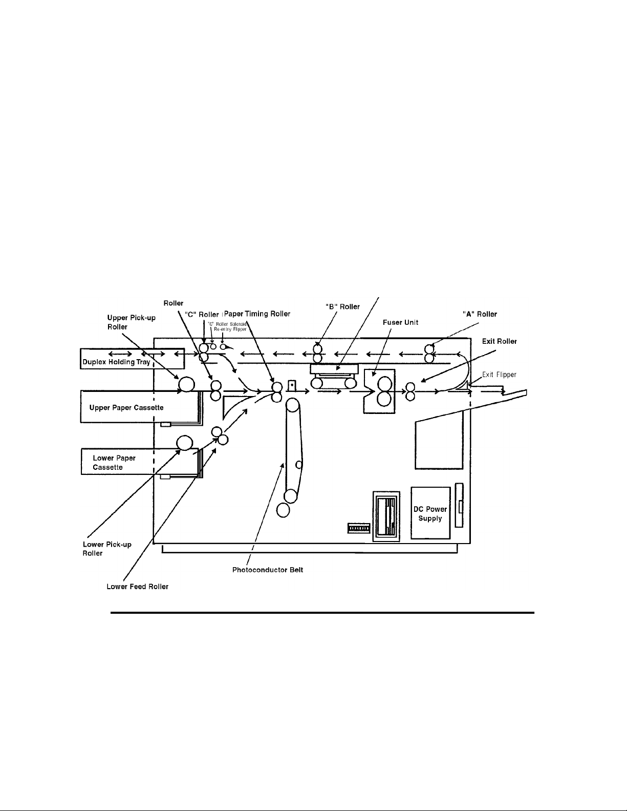
Paper Path and Cycle Sequence
The IGS board signals the PCL board th at a page of data is ready to be printe d. When thi s
happens the following sequence takes place.
Simplex Printing
1 PCL software downloaded to the PCL board from the disk drive system turns on the
main motor.
2 The PCL board engages the paper pick clutc h which causes the roll er to feed a sheet of
paper .
3 The paper is passed t o the f eed r oller where the PCL bo ard has en gaged t he fee d roll er
clutch.
4 The feed roll er passes the pa per to the paper timing roller. Prior to reaching the paper
timing roller, the paper passes over the paper timing sensor. (If the paper does not
energize this sensor in a specified amount of time, an error 020/021 will occur.) The
leading edge of the paper is registered against the paper timing roller. The paper tim-
ing clutch is engaged and the paper is passed over the photoconductor for transfer.
This registers the paper to the printer and the image to the paper. The paper timing
sensor sign al also alerts the PCL to in form the IGS that it can begin to send the data.
5 The PCL board engages the paper timing roller clutch and, at the same time, turns on
the transfer charger to provide a high positive voltage. The developed image on the
photoconductor comes in contact with the paper and the high positive voltage causes
the image to transfer to the p aper.
6 Because the toner is not yet fix ed to th e pape r, a vacuum transport assembly, gripping
the paper from the back side, moves the paper to the fuser unit, where heat and pres-
sure bond the toner to the paper.
7 Upon leaving the fuser unit, the paper comes in contact with the paper exit sensor. (If
the paper does not energize this sensor in a given amount of time after leaving the
paper timing sensor [step 4], an error 022 will occur.)
8 The exit roller moves the paper to the exit tray. (If the exit sensor is not cleared in a
specified amount of time, an error 023 will occur.)
Duplex Printing
When duplex is selected, the PCL board controls the paper motion with page scheduling
assistance from the IGS b oard. The duplex page rout er is enga ged. When in duplex mode,
it is important to note that th e printer runs mu ltiple pages through the paper path at the
same time to increase speed. (See Figure 1-2, “Paper Path,” on page 1-6.)
1 In a duplex job, the duple x router so lenoid behind t he fuser is engag ed and mecha nical
fingers route the paper to the duplex area. Also, the “A” roller clutch engages to turn
the “A” and “B” rollers (connected via a belt).
Printer and Troubleshooting Overview 1-5
Page 20
2 The paper upon passing through the “B” roller comes in contact with the duplex sen-
sor . ( If the paper doe s not energize this sensor in a giv en amoun t of ti me, an er ror 060
will occur.)
3 The “C” roller bidirectional motor turns on and passes the paper into the turnaround
tray. The paper sensor in the turnaround tray is activated and the paper is center registered. (If the paper does not energize this sensor in a given amount of time after leaving the duplex sensor, an error 061 will occur.)
4 At this time the solenoid for th e r out er at the turnaround t ra y enga ges so the paper can
be routed to be printed on the duplex side.
5 In a given amount o f time after the paper en ergize s the paper sensor in t he turnaroun d
tray, the bi-directional motor reverses and passes the p aper to the paper timing roller.
(If the paper do es not energize the paper timing sensor in a given am ount o f time after
leaving the turnaround sensor, an error 062 will occur.)
6 At this point, the same steps happen as during a simplex cycle.
Figure 1-2. Paper Path
1-6 Printer and Troubleshooting Overview
Page 21
Error Code Technical Definitions
The following table lists the printer error codes and their descriptions.
Table 1-1. Error Code Technical Definitions
T y pe Error Description
010, E10 PCL board detected no signal from upper paper cassette empty
011 PCL board detected no signal from lower paper cassette empty
012, E12 PCL board detected no signal from upper cassette in switch
013 PCL board detected no signal from lower cassette in switch
Cassette Errors
020 PCL board detected that the paper being fed from the upper cas-
021 PCL board detected that the paper being fed from the lower cas-
022 PCL board detected that the exit paper sensor did not activate or
023 PCL board detected that either:
sensor indicating no paper present
sensor indicating no paper present
sette did not reach the timing paper sensor within the allotted time
sette did not reach the timing paper sensor within the allotted time
the timing sensor did not deactivate within the allotted time
1. The exit paper sensor (within the printer) became activated but
did not deactivate within the specified time.
2. (HCO only). The paper exit sensor (within the HCO) did not
become activated or deactivated within the allotted time
025 PCL board detected that the timing paper sensor was activated
026 PCL board detected that either the exit paper sensor (within the
Paper Jams in the Primary Paper Path
027 PCL board detected paper in the duplex area after clearing a jam
030 PCL board detected a signal from the high-voltage power supply
031 PCL board detected a signal from the toner patch sensor board
032 PCL board detected a signal from the toner patch sensor board
035 PCL board detected too many successive signals from the toner
Toner Control Errors
036 PCL board detected no developer unit electrical interlock signal
immediately after one of the covers was closed
printer) or the paper exit sensor (within the HCO) was activated
immediately after one of the covers was closed
unit indicating an abnormal load on the bias voltage to either the
developer unit, cleaner unit, or printhead-cleaning bias plates.
indicating that the reference voltage level on the photoconductor
was too low.
indicating that the toner patch on the photoconductor was too light.
patch sensor board for a toner feed.
from the J25 connector.
Printer and Troubleshooting Overview 1-7
Page 22

Table 1-1. Error Code Technical Definitions (Continued)
Type Error Description
040 PCL board sensed that the signal from the photoconductor seam
sensor either was not of sufficient amplitude or did not show the
proper timing.
041 PCL board detected an abnormally high amount of current needed
to drive the photoconductor seam sensor LED (within the photoconductor unit).
042 PCL board detected an open connection to the photoconductor
seam sensor LED (within the photoconductor unit).
044 PCL board detected a signal from the high-voltage power supply
unit indicating that either the main charger or transfer charger circuits have an open connection.
045 PCL board detected a signal from the high-voltage power supply
OPC Rotation Errors
unit indicating an abnormally high load on the bias voltage to the
main charger.
046 PCL board detected a signal from the high-voltage power supply
unit indicating an open connection in the main charger circuit (diagnostic test only).
050 PCL board detected a signal from the high-voltage power supply
unit indicating an abnormally high load on the bias voltage to the
transfer charger.
051 PCL board detected a signal from the high-voltage power supply
unit indicating an open connection in the transfer charger circuit
(diagnostic test only).
HVPS Errors
055 PCL board detected that the current needed to drive the erase
lamp assembly was either higher or lower than the specified limits.
060 PCL board detected that the exit paper sensor did not deactivate
or the paper path sensor did not activate within the allotted time.
061 PCL board detected that the duplex paper path sensor did not
deactivate, the turnaround tray sensor did not activate in the allotted time, or the duplex paper path sensor activated at POR.
062 PCL board detected that paper leaving the duplex turnaround tray
Duplex Jams
did not reach the timing sensor within the allotted time or the
duplex turnaround sensor was activated at POR.
070 PCL board sensed, via the fuser thermistor, that the temperature of
the fuser unit did not change within the allotted time.
071 PCL board sensed an open connection in the fuser thermistor cir-
cuit
072 PCL board sensed that the resistance of the fuser thermistor was
too low indicating that the temperature of the fuser unit was higher
than the specified limit.
073 PCL board sensed that the resistance of the fuser thermistor was
Fuser Control Errors
too high indicating that the temperature of the fuser unit was lower
than the specified limit.
1-8 Printer and Troubleshooting Overview
Page 23
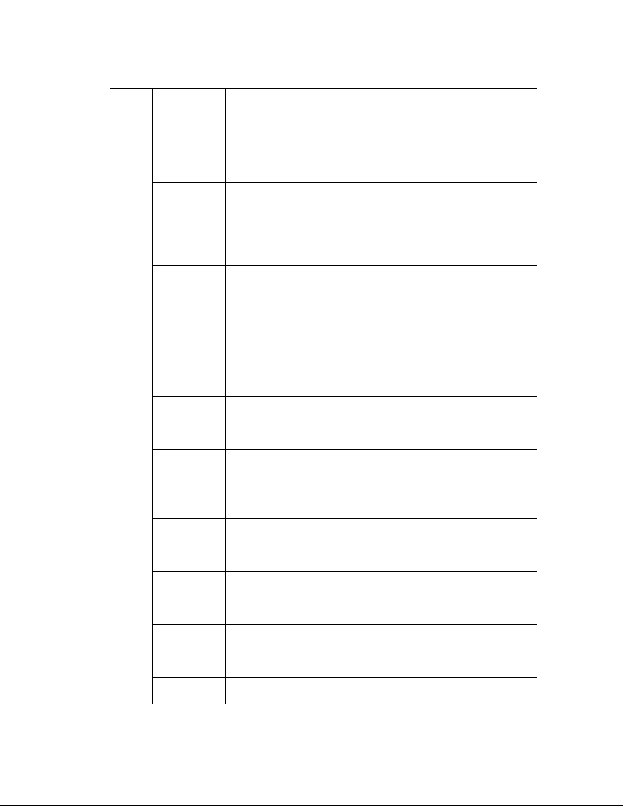
Table 1-1. Error Code Technical Definitions (Continued)
Type Error Description
081 PCL board activated the jogging motor but did not detect a change
in the signal from the front sensor in the job offset assembly (diagnostic test only).
082 PCL board activated the jogging motor but did not detect a change
in the signal from the rear sensor in the job offset assembly (diagnostic test only).
083 PCL board activated the jogging motor but did not detect a change
in the signal from either the front or rear sensors in the job offset
assembly.
084 PCL board detected a signal from the duplex control board #2 indi-
cating that the registration side sensor did not activate after command was sent to the duplex control board #2 to turn on the resist
motor (diagnostic test only).
Jogger Errors
085 PCL board detected a signal from the duplex control board #2 indi-
cating that the registration side sensor did not deactivate after a
command was sent to the duplex control board #2 to turn on the
resist motor (diagnostic test only).
086 PCL board detected a signal from the duplex control board #2 indi-
cating that either the registration side sensor was activated and
would not deactivate or was deactivated and would not activate
after a command was sent to the duplex control board #2 to turn on
the resist motor.
090 PCL board detected that one of the cover interlocks was not acti-
vated (diagnostic test only).
097 PCL board detected a signal from the IGS board indicating the
absence of +12 Vdc.
098 PCL board detected a signal from the IGS board indicating the
absence of ‚-12 Vdc.
LVPS Errors
099 PCL board detected a signal from the IGS board indicating the
absence of +24 Vdc.
100, 102 IGS board detected a failure of the PCL board status codes.
101 PCL board detected that the IGS board was in a halt state (diag-
nostic test only).
121-127 PCL board detected an error in the communication between the
PCL board and the IGS board.
130-134 PCL board detected an error during the internal diagnostic testing
of the PCL board.
140 PCL board detected an error during the internal diagnostic testing
of the PCL board.
145 PCL board detected an error during the internal diagnostic testing
of the PCL board.
Controller Errors
160-182 PCL board detected an error during the internal diagnostic testing
of the PCL board.
199-215 PCL board detected an error in the communication between the
PCL board and the IGS board.
301-401 IGS board detected an error during the internal diagnostic testing
of the IGS board.
Printer and Troubleshooting Overview 1-9
Page 24

Table 1-1. Error Code Technical Definitions (Continued)
Type Error Description
405-409 IGS board detected an error in the program RAM during the inter-
450-566 IGS board detected an error during the internal diagnostic testing
DD Errors
570-586 IGS board detected an error when communicating with the floppy
600-610 IGS board detected an error during the internal diagnostic testing
Errors
Controller
701-703 IGS board detected an error when communicating with a host
770-784 IGS board detected an error when communicating with a host
Errors
888 IGS board detected that the PCL board was in a halt or reset state.
Communication
nal diagnostic testing of the IGS board.
of the IGS board and software.
disk drive.
of the IGS board.
using RS232 communications.
using RS422 communications.
1-10 Printer and Troubleshooting Overview
Page 25

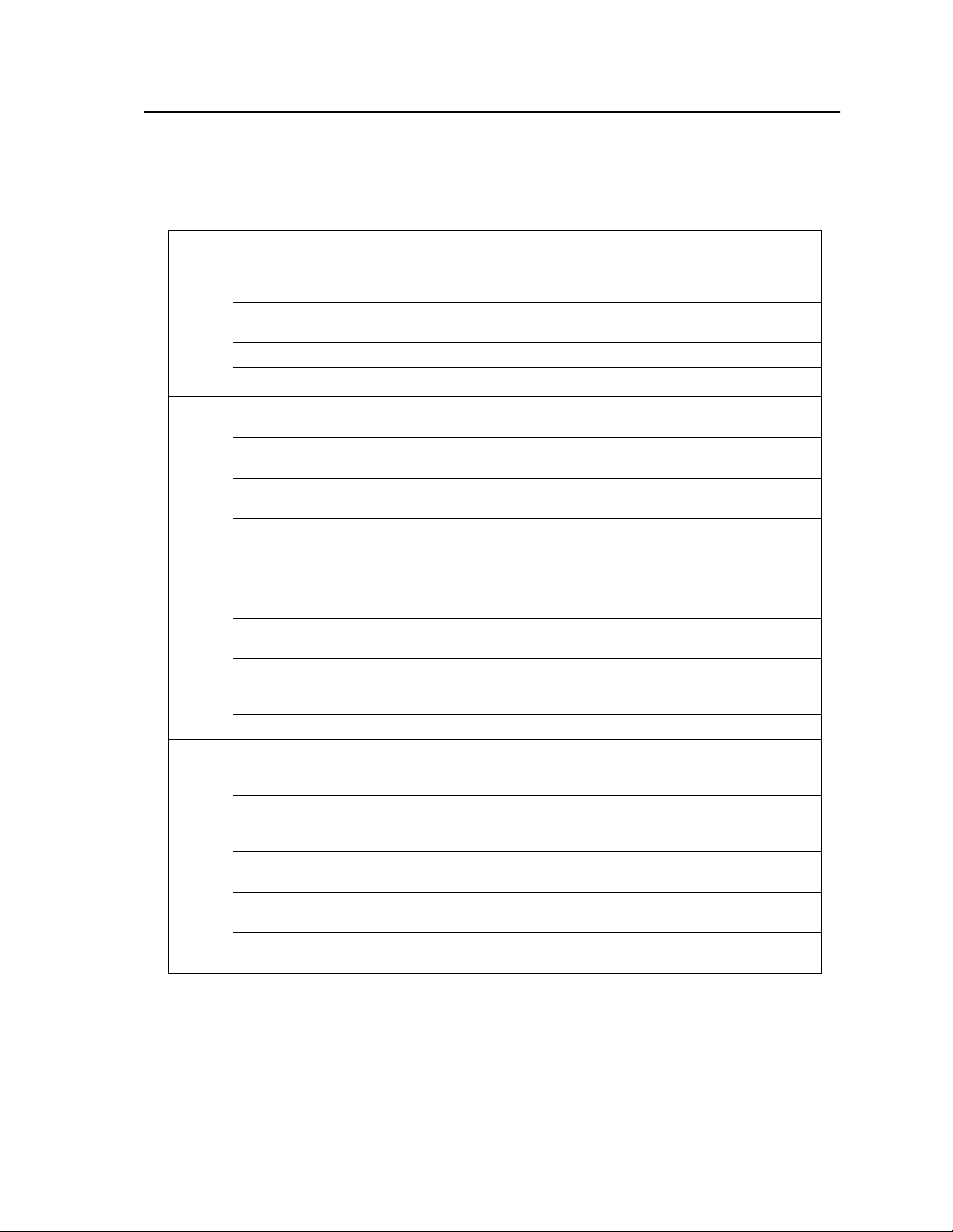
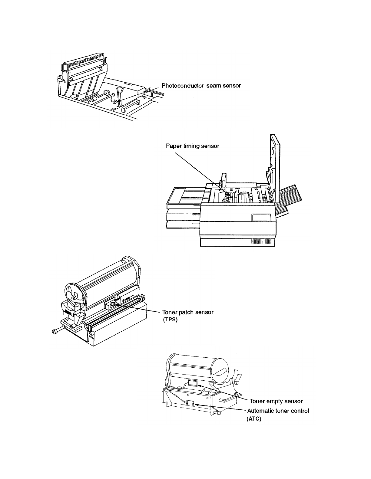
Sensor and Switch Locations
The following pages illustrate the locations of the printer’s sensors and switches. Table 1-
2, “Sensor and Switch List,” on page 1-14, lists them.
Left end view
Left end view
Front left view
Top view, duplex
Printer and Troubleshooting Overview 1-11
Page 26
Top view
Front view
Developer right view
Developer left view
1-12 Printer and Troubleshooting Overview
Page 27

Right side view
Top left, duplex tray view
Front view
Printer and Troubleshooting Overview 1-13
Page 28
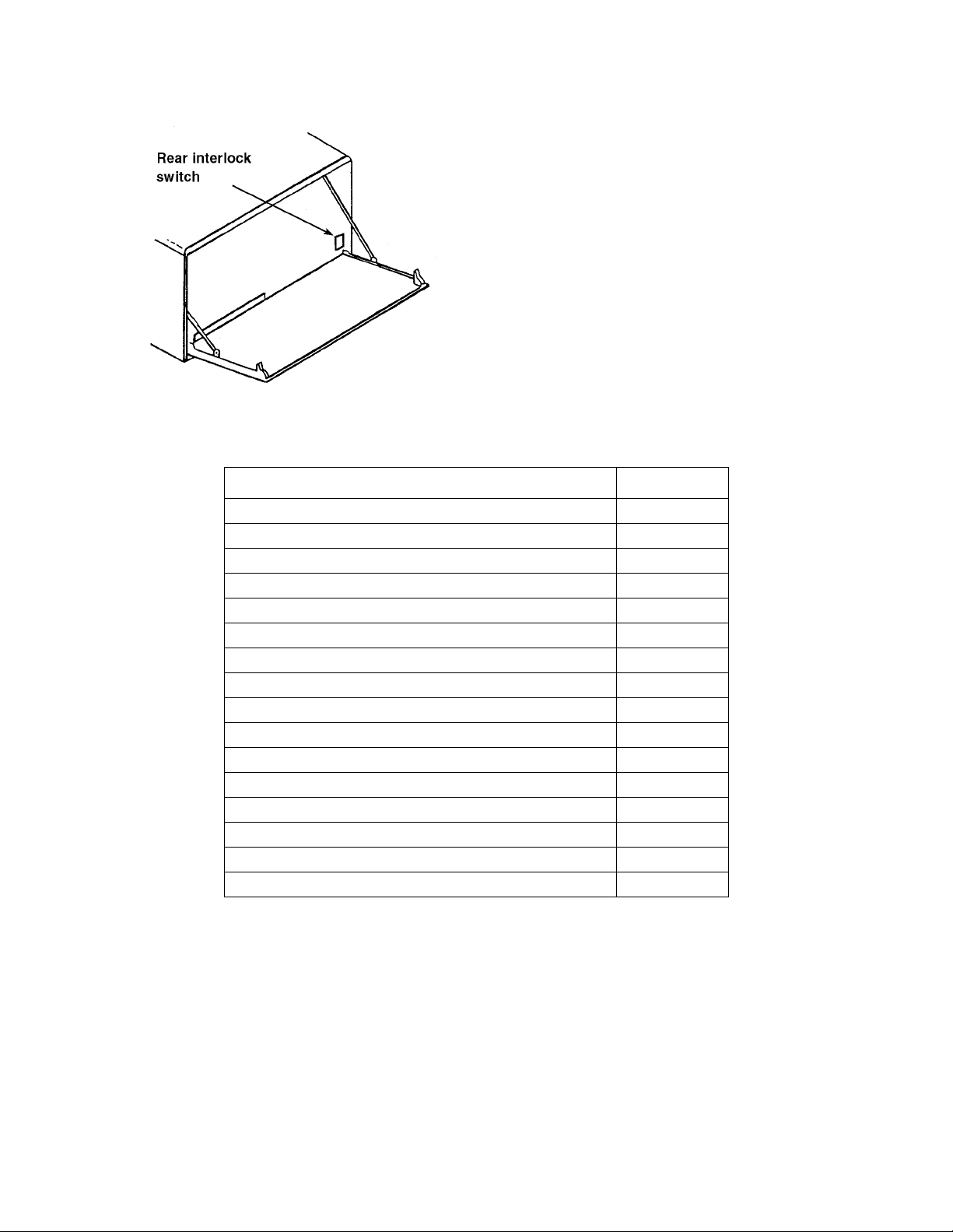
Rear view
Table 1-2. Sensor and Switch List
Sensor/Switch Name Page No.
Automatic toner control sensor 1-12
Cassette paper present sensors, upper and low er 1-11
Cassette present micro switches, upper and lower 1-11
Duplex registration sensor 1-11
Duplex paper path sensor 1-11
Duplex cover interlock switch 1-11
Interlock switch, top 1-13
Interlock switch, front 1-13
Interlock switch, rear 1-14
Paper exit sensor 1-13
Paper full sensor 1-13
Paper size sensors, upper and lower 1-11
Paper timing sensor 1-12
Photoconductor seam sensor 1-12
Toner empty sensor 1-12
Toner patch sensor 1-12
1-14 Printer and Troubleshooting Overview
Page 29

Troubleshooting Overview
Throughout the printer’s life problems occur, such as those indicated when an error code
displays on the operator panel, a printer produces poor quality prints, or the printer malfunctions. Use the t ool s pr ovi de d in this manual to dia gnos e and resolve printer problems.
These tools include:
• The Troubleshooting Analysis Guide, which contains troubleshooting procedures
called TAGs. TAG 001: Troubleshooting A Printer Problem provides an overview of
how to use TAGs.
• Cross reference tab les, which link e rror codes, prin t quality probl ems, and mechanical
malfunctions to specific TAGs.
• Print quality samples, which you can use to identify a printing problem and its associ-
ated TAGs.
• Diagnostics, through which the printer checks itself for a range of problems.
The next several pages revi ew troubleshoot ing basics and standar d procedures followed in
every troubleshooting session, including:
• Identifying whether a problem belongs to the printer or host
• Isolating protocol converter problems
• Running test prints
• Reading the error log
• Confirming line power
• Using TAGs
• Power-On Reset
• Installing the interlock by-pass tool
• Checking continuity
• Producing a developed image
• Producing a toner patch
• Completing a service call
• Clearing the error log
General Troubleshooting Tips
When a printer problem arises, swapping out all printer supplies may temporarily mask
the problem. This is an unsat isfacto ry , short-t erm, and ex pensive solution to correcting the
proble m. Dust and other contamination, rather than printer supplies, are more often the
causes of problems. Clean consumable connectors, alignment guides, and areas before
changing consumables.
Many failures add excess toner to the printer’s engine. When you are advised to de-tone
the printer as part of a problem fix, run at least 200 test prints before evaluating whether
the problem has been resolved.
Printer and Troubleshooting Overview 1-15
Page 30

The Problem: Printer or Host?
The printer is one component in a lar ge host s ystem. Before you start any troubleshoot ing,
make sure that the problem really belongs to the printer rather than to some other component in the host system. Print quality problems and mechanical malfunctions are almost
always associated with the printer. However, host interface and software emulation problems can be caused by some other component of the host system even though, at first Z
glance, they appea r to be printer probl ems. For ins tance, text print ed in t he wrong lo catio n
on a page, improper page breaks, and missing segments of data strongly indicate a host,
not a printer, problem.
The first step i n trou blesho oting any pr oblem i s to isola te t he pri nter from t he hos t sy stem;
you can then run test prints. Producing test prints exercises the printer as a stand-alone
ones machine, ensuring that the basic printer software and all mechanical functions of the
printer are working.
Running Test Prints
To run test prints:
1 Disconnect the host interface.
2 Run a series of test prints. A di re cto ry of the boot device and multiple listing s of fonts
print, followed by an unformatted and formatted error log. A continuous flow of the
test pattern then prints. To run test prints:
• For simplex printers, press:
STOP
TEST
• For duplex printers, press:
STOP
DUPLEX
TEST
• To stop printing t he test pattern, press:
STOP
On pressing STOP, the printer will print all test prints stored in the printer’s buffer, then
stop.
If the test pattern prints suc cessfull y, the problem probably originates with the host syste m
or a protocol converter connected to the host.
1-16 Printer and Troubleshooting Overview
Page 31

Protocol Converters
Many protocol converters have a self-test function or configuration mode that enables the
user to check the proper functioning of the control. You can reconnect the host interface
and ask the customer to exercise this function of the converter. If the printer receives data
and prints it (even if the output is garbled) you have isolated the problem as one that
belongs to the host or the prot ocol con verte r. The problem is not a printer problem and the
customer must seek assistance elsewhere in resolving the problem.
Reading the Error Log
One of the sheets printed prior to the test pattern is the formatted error log maintained by
the printer in a file named ERROR.LOG.
• The first line of the formatted log lists paper jams. A 3-dig it error code (or codes) is
followed by a 4-digit number indicating how many times the error has occurred since
the error lo g was last cleared. (See “Clearing the Error Log” on page 1-24.)
• The second line lists the last 15 errors.
• The last line indicates the last error that required a power-on-reset (POR).
Paper Jams
020 0001 021 0000 022 0001
023 020 020 022 022 022 022 071 042 000 000 000 000 000 000
000
Last error requiring POR (not used)
Figure 1-3. Sample Simplex Printer Error Log
Last 15 errors
Printer and Troubleshooting Overview 1-17
Page 32

Confirming Line Power
Erratic printer problems can be caused by improper line power. As a rule, the voltage of
the outlet should be checked at installation. However, if you are unable to isolate an inter-
mittent problem, the power shoul d be chec ked agai n. Consul t your co untry’s national electric code for the proper procedures to check for acceptable voltages, as shown in Table 1-
3, “Acceptable Voltages”.
Table 1-3. Acceptable Voltages
Probe connections 100-127v printer 200-240v printer
red to AC hot
black to AC neutral
red to AC neutral
black to ground
red to AC hot
black to ground
120v +/- 10% 230v +/- 10%
3 vac or less 3 vac or less
120v +/- 10% 230v +/- 10%
Please see Chapter 5, “Dia gnostic Test s” for additional information about running diagnostic printer tests.
Please see Chapter 6, “Wiring Diagrams and Electrical Data” for additional information
about the printer’s electrical systems.
1-18 Printer and Troubleshooting Overview
Page 33

Using the Troubleshooting Analysis Guide (TAG)
The Troubleshooting Analysis Guide provides problem-solving sequences to help you
identify and resolve printer problems. Each TAG addresses a particular symptom or error
code of the printer. The TAG number often matches an error code displayed on the
printer’s operator panel.
Sample TAG
TAG 001: Troubleshooting a Problem
Error Code: All related error messages are listed here.
Possible Causes: All possible causes are listed here.
Possible Defects: All possible defective parts are listed here. (In no particular order.)
1
To start:
• Disconnect all peripheral cables
• Power-on-reset the printer.
Did all of the status lights come on, followed by 888 flashing briefly and an error code?
Yes: Run test prints, following the procedure outlined in Section 1, then repeat this step. If the
answer is still no, refer to the mechanical malfunctions cross-reference chart in Section 2
to determine which TAG to follow. Then turn to that TAG.
Yes: Note the error message and continue.
2
3
Power-on-reset the printer.
Did the power-on-reset end with an error code?
No:
Continue.
Yes: Refer to the error code cross-reference table in Section 2, using either the code that dis-
played after steps 1 and 2, or if multiple error codes conti nue to appear, the first error
code that displays. Turn to the TAG associated with the code.
Did only the READY light come on with no numeric display?
No: Continue
Yes: Go to TAG 753
Each TAG walks through a comprehensive procedure specifi c to a si ngle pr oblem. As y ou
progress through a TAG and eliminate possible causes, you may be directed to another
step out of sequence in the same TAG or to another TAG altogether.
The TAG number and its title may be followed by a listing of possible error messages,
possible causes, or possible defective parts related to the TAG.
Printer and Troubleshooting Overview 1-19
Page 34

The TAG then directs you to perform cert ai n t as ks. Based on the resul ts of t hes e tasks, the
TA G poses questions that can be answered by either yes or no. For yes answers, you follow one path; for no answers, follow another path. Some of the paths may lead you to
other TAGs, so that you can methodically diagnose and re solve problems . When you ha ve
corrected a problem, you will be directed to TAG 002 to confirm that the problem has been
completely resolved and standard cleanup procedures observed.
If it’s not clear how t o diagnose a problem y ou’r e work ing on, follow the ste ps outlined in
TA G 001, which includes references to the cross reference tables contained in Chapter 2,
“TAG Cross- Reference Tables”. Or, you may turn directly to the tables to get started.
As you use TAGs, you will sometimes refer to othe r s ect i ons of this manual for addi ti onal
information:
• Chapter 4, “Print Quality Samples” contains print quality samples you’ll use to com-
pare the customer’s test prints with flawed and good print samples.
• Chapter 5, “Diagnostic Tests” outlines how to conduct printer diagnostic tests.
• Chapter 6, “Wiring Diagrams and Electrical Data” provides all wiring and connector
diagrams.
• Chapter 7, “Removal/Replacement Procedures” provides step-by-step procedures for
removing and replacing all field-replaceable parts on the printer.
• Chapter 8, “Options” reviews printer options (HCI, HCO) information.
• Chapter 9, “Gener al Pri nter M aint enance” presents general printer maintenance pr oce-
dures.
1-20 Printer and Troubleshooting Overview
Page 35

Standard Procedures
While using the TAGs, you may be asked to perform some of the following procedures.
Specific instructions for completing these procedures are included here, rather than
repeated in the body of each TAG. Please read this information before following any TAG.
Power-on-reset (POR)
When directed to power-on-reset the printer:
1 Turn of f the printer.
2 Wait at least 5 seconds.
3 Turn the power back on.
Checking Continuity
Make sure the printer is turned off and the power disconnected.
Failure to do so may result in personal injury, equipment damage,
or both.
Warning
To perform a continuity check:
1 Turn off the printer and disconnect the power cord.
2 Set your meter to the lowest ohm setting.
3 Interpret the results as follows:
• An infinite reading indicates an open circuit.
• A zero or specific reading indicates continuity.
4 To check an open or short circuit to ground:
• Turn off the printer and disconnect the power cord.
• Locate the circuit in que stion. (Refer to Chapter 6, “Wiring Diagrams and Electri-
cal Data”, for circuit loca tions.)
• Check all connectors and wiring on each side for corrosion, foreign objects, bent
pins, loose socket housings, and/or loose wires.
Warning
The printer is equipped with safety interlock switches on all of
its covers. These switches disable parts of the printer when the
covers are opened. These areas present the risk of electrical
shock, burns, and injury from mechanical hazards.
Printer and Troubleshooting Overview 1-21
Page 36

Installing the Interlock By-pass Tool
The interlock by-p ass tool overri des the cover i nterlock switches , allowin g you to operate
the printer with the c overs open . The interl ock by-pas s tool is a whit e plasti c, “V”-sh aped
tool with two finger pads. To use the tool, open the cover and locate the interlock switch
(for locations, se e il lustr ation s begi nning p age 1- 11). Squeeze the tool between thumb and
fore finger and insert it into the interlock switch.
The printer ships with two spare interlock by-pass tools concealed behind the right cover.
Replace them when you are finished using them.
Caution
Do not attempt to close the printer cover while the interlock
bypass tool is in place.
Producing a Developed Image
Producing a developed image helps determine where exactly in the print cycle a problem
may be occurring. To produce a developed image:
1 Open the top cover and install an interlock by-pass tool.
2 Power-on-reset the printer.
3 Run a series of test prin ts. The direc tory o f the boot de vice wi ll pr int, f ollowe d by con -
tinuous test patterns.
4 As test patterns print, observe paper moving from the upper paper tray to the paper
timing roller w here it pauses briefly.
5 When a sheet of paper be gin s to move from th e pape r timing r oller, turn off the printer.
6 Remove the photoconductor unit.
7 Examine the photoconductor belt to verify that a developed image was produced.
Producing a Toner Patch
To produce a toner patch:
1 Turn of f the printer.
2 Open the top cover and install an interlock by-pass tool.
3 Turn on the printer.
4 Start running test prints using Simplex Print mode. When the leading edge of the first
print enters the fuser unit, remove the interlock by-pass tool.
1-22 Printer and Troubleshooting Overview
Page 37
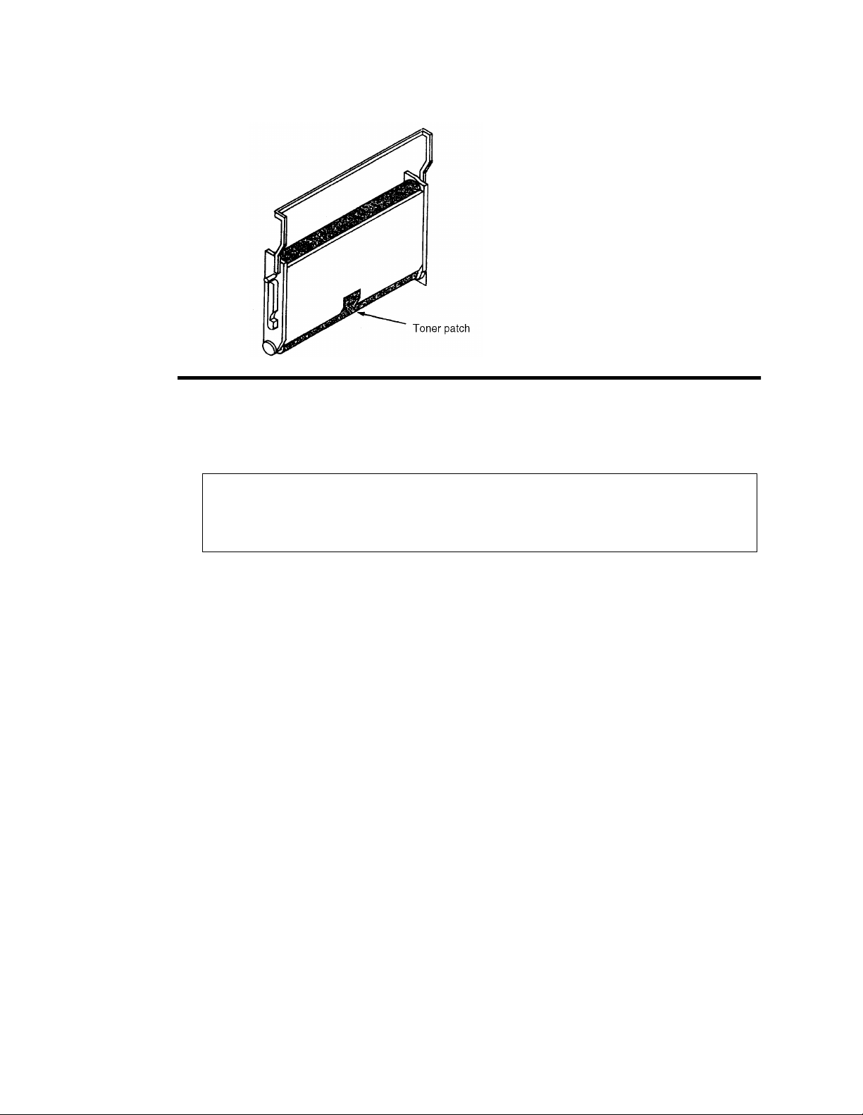
5 Remove the photoconductor unit.
Figure 1-4. Producing a Toner Patch on the Photoconductor Unit
6 Examine the photoconductor unit to verify that a toner patch has been produced. You
may have to rotate the belt slightly to observe the patch.
Caution
Do not touch the surface of the photoconductor belt; this
damages the belt and results in poor print quality.
Completing a Service Call
After resolving any printer problem, complete the service call as follows:
1 Reassemble the printer.
2 Perform the every-call cleaning procedure, described in Chapter 9, “General Printer
Maintenance”.
3 If you have removed the printer’s diskette(s), reinstall them.
4 Power-on-reset the printer.
5 Clear the error log. (See the procedure described next.)
6 Run test prints in both the simplex and duplex mode from both the upper and lower
paper cassettes.
7 Fill in the Repair/ Maintenance log. Make sure the probl em descri ption and s teps take n
to resolve the problem are clearly documented.
Printer and Troubleshooting Overview 1-23
Page 38

Clearing the Error Log
1 Enter the dia gnostic mode of the printer:
• Turn off the printer and wait 5 seconds.
• Hold down the STOP and TEST keys simultaneously as you turn the printer back
on.
• The tone, followed by “00” on the di spla y, indicates you are in the test mode. Th is
takes approximately 1 minute.
2 Press: CANCEL to advance the counter to “110.”
3 Press READY to activate the procedure. “0” appears on the display, indicating the A:
drive.
4 Press: CANCEL to advance to the drive where the error l og is maint ained. This i s usu-
ally the boot drive.
Table 1-4. Drive Indication
Display Indication
0 Diskette drive A:
1 Diskette drive B:
2 Hard drive C:
5 Press: READY to select the drive specified. “1-0” appears on the display.
Caution
At this point, be careful! “1-0” represents the clear error log
function. Do not advance the counter to “1-1,” which represents
the format disk option.
6 Press: READY to select the clear error log function. “6-0” appears on the display.
Caution
If “7-0” appears, press STOP immediately. DO NOT CONTINUE
WITH THIS PROCEDURE. POR the printer and start over.
7 Press: CANCEL to clear the error log. “6-1” appears on the display.
8 Press: STOP to exit the procedure.
9 Cycle printer power to exit diagnostic mode.
10 Confirm that the error log has been cleared. When you run your test prints, check to
make sure the error log entries appear as “0000.”
1-24 Printer and Troubleshooting Overview
Page 39

Chapter 2
TAG Cross-
Reference Tables
TAG Cross- Reference Tables 2-1
Page 40

TAG Cross-Reference Tables
TAG Cross-Reference Tables
This section contains the three cross reference charts for troubleshooting print problems:
Error Code/TAG Cross-Reference Chart . . . . . . . . . . . . . . . . . . . . . . . . . . . . . . . . .2-3
Print Quality/TAG Cross-Reference Chart . . . . . . . . . . . . . . . . . . . . . . . . . . . . . . .2-9
Mechanical Malfunction/TAG Cross-Reference Chart . . . . . . . . . . . . . . . . . . . . .2-12
2-2 TAG Cross- Reference Tables
Page 41

Error Code/TAG Cross-Ref erence
Error Code/TAG Cross-Reference
Error codes, which appear on the 3-digit display of the operator’s panel, indicate a wide
variety of printer problems related to the control boards, software, and/or host communication problems. On th e chart fi nd the e rror c ode in qu est ion, th en turn to TAG associated
with the code.
Table 2-1. Printer Error Codes
Code Printer Error Code Meaning Go to TAG
010 Upper paper tray out of paper 010
011 Lower paper tray out of paper 011
E10 Envelope feeder out of envelopes E10
012 Upper paper tray not plugged in 012
013 Lower paper tray not plugged in 013
E12 Envelope feeder not plugged in E12
020 Upper paper tray paper jam 020
021 Lower paper tray paper jam 021
022 Transfer or fuser area paper jam 022
023 Exit area paper jam 023
025 Transfer or fuser area paper jam not cleared 025
026 Exit area paper jam not cleared 026
027 Duplex area paper jam 902
030 Developer bias short 030
031 Toner patch sensor reference level too low 031
032 Toner patch sensor black patch too light 032
035 No toner 035
036 No developer 036
040 Photoconductor seam sensor malfunction 040
041 Photoconductor seam sensor short 040
042 Photoconductor seam sensor open 040
044 Main charger open 044
045 Main charger short 045
046 Main charger open 044
050 Transfer charger short 050
055 Eraser lamp malfunction 055
057 Fan stopped sensor 752
060 Duplex area 1 paper jam 902
061 Duplex area 2 paper jam 902
062 Duplex area 3 paper jam 902
069 Duplex tray not plugged in 900
070 Fuser lamp or thermal fuse malfunction 070
TAG Cross- Reference Tables 2-3
Page 42

Table 2-1. Printer Error Codes (Continued)
Code Printer Error Code Meaning Go to TAG
071 Fuser thermistor open or no fuser 071
072 Fuser temperature too high 072
073 Fuser temperature too low 070
081 No front job offset sensor 083
082 No back job offset sensor 083
083 Job offset mechanism malfunction 083
084 Duplex tray registration sensor not activated 901
085 Duplex tray registration sensor not deactivated 901
086 Duplex registration tray malfunction 901
090 Cover open 900
097 DC +12v power failure 097
098 DC -12v power failure 098
099 DC +24v power failure 099
100 PCL board command timeou 100
101 IGS controller diagnostic failure 101
Table 2-2. PCL/IGS Communication Error Codes
Code PCL/IGS Communication Error Code Meaning Go to TAG
121 No controller command; PCL board VSC command asserted 201
122 Command tag asserted; VSC command not asserted 201
123 VSS not asserted; PCL board status tag asserted 201
124 VSS asserted after PCL board sent status 201
125 VSS not asserted again though PCL board expects it 201
126 Command tag asserted during data byte sequence 201
127 PCL board detected parity/overrun on command line 201
Table 2-3. PCL Error Codes
Code PCL Error Code Meaning Go to TAG
130 Address or length error at initial microcode load 130
131 Checksum error at initial microcode load 130
132 RAM error at initial microcode load 100
133 No next block at initial microcode load 130
134 Incorrect format in initial microcode load file 130
140 PCL board ROM checksum error at power on diagnostic 100
145 PCL board RAM error at power on diagnostic 100
2-4 TAG Cross- Reference Tables
Page 43

Table 2-3. PCL Error Codes (Continued)
Code PCL Error Code Meaning Go to TAG
160 PCL board PIA1 register error after reset 100
161 PCL board PIA1 registers read/write error 100
162 PCL board PIA1 PA or PB read/write error 100
170 PCL board PIA2 register error after reset 100
171 PCL board PIA2 register read/write error 100
172 PCL board PIA2 PB read/write error 100
180 PCL board PTM register error after reset 100
181 PCL board PTM read/write error 100
182 No IRQ generation on PTM 100
Table 2-4. PCL/IGS Communication Error Codes
Code PCL/IGS Communication Error Code Meaning Go to TAG
199 VSS not asserted before communication test 201
200 Status tag not asserted 201
201 Timeout waiting for a failed IGS controller 201
202 No data received after VSS line asserted 201
203 VSS asserted after PCL board sent status 201
204 Status tag asserted after VSS not asserted 201
205 No command tag after status tag not asserted 201
206 VSC command not asserted after command tag asserted 201
207 No data r eceived after VSC asserted 201
208 VSC command asserted after command line asserted 201
209 Command tag asserted after VSC not asserted 201
210 No RQI after “request RQI” command 201
211 Parity error on command line 201
212 Parity or overrun sensed by PCL board 201
213 Incorrect command received from PCL board 201
214 Incorrect command received from IGS controller 201
215 No transfer buffer empty on asynchronous communications
interface adapter after PCL board sent data
201
TAG Cross- Reference Tables 2-5
Page 44

Table 2-5. IGS Firmware Error Codes
IGS Firmware Error Code Meaning
Code
These error codes signal a problem with the IGS controller
firmware. No TAGs address these problems; report them to the
printer’s manufacturer.
301 Status received after VSS asserted No T AG
302 Status tag asserted after VSS not asserted No TAG
303 VSC command not asserted after command tag asserted No TAG
304 VSC command asserted after data was sent No T AG
305 VSC command not asserted for next data byte No T AG
306 Status tag asserted while data was being sent No TAG
307 Parity error on command line No T AG
Table 2-6. PCL Failure Error Codes
Code PCL Failure Error Code Meaning Go to TAG
380 PCL board failure - command retries 201
381 PCL board failure - command rejected 201
382 PCL board failure - bad command received 201
383 PCL board failure - unexpected byte received 201
384 PCL board failure - no status received 201
385 PCL board failure - bad status information block count 201
386 PCL board failure - bad status information block offset 201
387 PCL board failure - parity error 201
389 Floppy disk retry 130
Go to TAG
Table 2-7. IGS Software Error Codes
IGS Software Error Code Meaning
These error codes signal a problem with the IGS controller
Code
software. No TAGs address these problems; to determine
Go to TAG
whether the faulty software is the customer’s or the
manufacturer’s, contact the printer’s manufacturer.
397 IGS software trap No TAG
398 IGS software trap No TAG
399 IGS software trap No TAG
2-6 TAG Cross- Reference Tables
Page 45

Table 2-8. IGS/Disk Drive Error Codes
Code Disk Drive Error Code Meaning Go to TAG
401 Fatal IGS PB error No TAG
450 Incorrect diskette 130
451 Diskette format error or incorrect disk 130
454 Fatal trap 200
455 Trap 200
500 Incorrect PIT0 registers contents; no reset 200
501 PIT0 register read/write error 200
502 No countdown/zero detection in PIT0 timer 200
503 PIT0 timer; no halt 200
504 No PIT0 timer interrupt 200
505 Incorrect PIT2 registers contents; no reset 200
506 PIT2 register read/write error 200
507 No countdown/zero detection in PIT2 timer 200
508 PIT2 timer; no halt 200
509 No PIT2/timer interrupt 200
520 No DMAC reset 200
521 DMAC registers read/write error 200
522 No DMA transfer 200
523 No DMA transfer termination 200
524 No DMAC termination interrupt 200
525 No software abort operation 200
526 No software abort interrupt 200
527 DMAC operation error 200
528 DMA transfer error 200
529 Two-channel DMA transfer error 200
530 No two-channel DMA transfer 200
540 PCL board serial controller registers read/write error 200
541 PCL board break condition detected 200
542 PCL board serial controller transmitter not ready 200
543 No PCL board serial controller transfer 200
544 PCL board serial controller transfer error 200
545 Host serial controller registers read/write error 200
546 Host transmitter not ready 200
547 No serial controller interrupts 200
548 Host serial controller/PCL board parity error 200
549 Serial controller unexpected interrupt 200
TAG Cross- Reference Tables 2-7
Page 46

Table 2-8. IGS/Disk Drive Error Codes (Continued)
Code Disk Drive Error Code Meaning Go to TAG
550 Two-channel transfer error 200
551 No PCL board/serial controller interrupt on break 200
552 No serial contr oller /DM AC int er action 2 00
553 Serial controller/DMAC transfer count error 200
554 Serial controller/DMAC transfer error 200
555 RS232 se nd/rec ei ve path error 200
556 RS232 DTR/DTC path error 200
557 RS232 RTS/CTS path error 200
558 RS422 se nd/rec ei ve path error 200
559 RS422 send clock/receive clock path error 200
560 CRTC register read/wri te error 200
561 No page begin (PIT2) interrupt 200
562 No CRTC address generation 200
563 No VSYNC generation (end of page) 200
564 No end of page (PIT2) interrupt 200
565 No CRTC count termination 200
566 VSYNC timeout error 200
570 Drive controller/SCSI read/write error 200
571 Drive controller busy timeout 200
572 Diskette is write protected 130
573 Drive not ready 130
574 Drive controller restore error 130
575 Drive controller seek error 130
576 Drive controller read sector error 130
577 Drive controller read sector data/checksum error 200
578 Drive controller write sector error 200
579 Drive controller read/modify/write error 200
580 No drive controller/PIT0 interrupt 200
581 No drive controller-DMA interaction 200
582 Drive controller/DMAC transfer error 200
583 Drive controller/DMAC transfer count error 200
584 Drive controller/DMAC read sector error 200
585 Drive controller/DMAC write sector error 200
586 Drive hard error 130
2-8 TAG Cross- Reference Tables
Page 47

Print Quality/TAG Cross-Reference
Table 2-9. Bit Map RAM Error Codes
Code Bit Map RAM Error Code Meaning Go to TAG
600 Bit-map RAM data path error 200
601 Bit-map RAM bank selection error 200
602 Bit-map RAM refresh error 200
603 Bit-map RAM address path error 200
604 Incorrect ALU operation in bit-map RAM data path 200
605 Incorrect origin data modifications 200
606 Total bit-map RAM bank fault 405
610 Bit-map RAM chip error 405
Table 2-10. Host Communication Error Codes
Code Host Communication Error Code Meaning Go to TAG
701 No communication with host 753
702 Host communication protocol error 753
703 Host communication recoverable error 753
770-784 Ethernet communication error No TAG; con-
tact software
support
Print Quality/TAG Cross-Reference
Poor quality prints are another indication of printer problems. Begin by running a set of
test prints. Then, compare the test prints to the samples located in Chapter 4, “Print Qual-
ity Samples”. The chart summarizes the possible print quality problems you may encoun-
ter and recommends a TAG to follow to address the problem.
Table 2-11. Blank Print TAGs
Blank Prints Go to T AG
Complete 800
Partial 800
With dark horizontal bands 800
TAG Cross- Reference Tables 2-9
Page 48

Print Quality/TAG Cross-Reference
Table 2-12. Light Print TAGs
Light Prints Go to TAG
With carrier particles 801
With background 811
With voids/white spots 802
With light vertical streaks 803
With blank or white vertical lines 803
With light horizontal bands 804
T able 2-13. Dark Print TAGs
Dark Prints Go to TAG
Dark black prints 805
With dark spots or scratches 806
With dark blotches 810
With dark vertical streaks (without fusing) 812
With dark vertical streaks (with fusing) 808
Table 2-14. Skewed Path TAGs
Simplex 807
Duplex 901
Table 2-15. Misregistration TAGs
Misregistered Prints Go to TAG
Simplex 807
Duplex 901
Skewed Prints Go to TAG
2-10 TAG Cross- R eference Tables
Page 49
Print Quality/TAG Cross-Reference
Table 2-16. Smeared, Blurred, and Uneven Print TAGs
Smeared, Blurred, Uneven Prints Go to TAG
Smeared vertical streaks 809
Blurred prints 809
Uneven density 810
Prints with background 811
Prints with background and residual images 811
Prints with residual images 813
Prints with offset images 814
Table 2-17. Additional Print Quality Problem TAGs
Additional Print Quality Problems Go to TAG
Wrinkled or torn prints 706
Prints improperly fused 812
Prints exhibiting printhead problems 815
TAG Cross- Reference Tables 2-11
Page 50

Print Quality/TAG Cross-Reference
Mechanical Malfunction/TAG Cross-Reference
The chart below outlines possible mechanical malfunctions and recommends an appropriate TAG to follow to resolve the problem.
Table 2-18. Operator Panel Problems TAGs
Operator Panel Problems Go to TAG
Blank with AC power fan and cooling fan on 500
Blank with AC power fan on 500
Blank with no fans on 600
All lights on 610
Incomplete display immediately after POR 610
Close cover light remains on 6 00
Remove prints light remains on or lights 700
Add toner light remains on 035
Machine check light is on with no numerical Display 201
One or more lights are off at POR 610
Tone not working 610
Incorrect paper size 702
Other operator panel malfunctions 610
Table 2-19. Output Tray Problem TAGs
Output Tray Problems Go to TAG
Sensor not sensing condition 701
Jogging incorrectly 083
Will not stop jogging 083
Job offset incorrect 083
Table 2-20. Cassette Problem TAGs
Cassette Problems Go to TAG
Upper cassette 703
Lower cassette 704
2-12 TAG Cross- R eference Tables
Page 51
Table 2-21. Paper Handling Problem TAGs
Paper Handling Problems Go to TAG
Multiple paper feed 705
Multiple sheet feeds and jams 705
Wrinkled or torn paper 706
Simplex: misregistration and paper skew 807
Duplex: misregistration and paper skew 901
Paper will not feed from upper cassette 012
Paper jam in duplex area 902
Upper paper guide not closing 707
Table 2-22. Counter Problem TAGs
Counter Problems Go to TAG
Print Quality/TAG Cross-Reference
Supplies seem to have short life span 750
Incorrect counting 750
f
Table 2-23. Communication Problem TAGs
Communication Problems Go to TAG
Printer will produce test prints 753
Incorrect data being printed 753
Table 2-24. Additional Mechanical Malfunction TAGs
Additional Mechanical Malfunctions Go to TAG
Test prints won’t run after POR 130
Cooling fan not running 752
Vacuum transport unit fan not running 752
Circuit breaker trip 600
Main drive motor not turning off 751
TAG Cross- Reference Tables 2-13
Page 52

Print Quality/TAG Cross-Reference
2-14 TAG Cross- R eference Tables
Page 53

Chapter 3
Troubleshooting
Analysis Guide
(TAGs)
Troubleshooting Analysis Guide (TAGs) 3-1
Page 54

Troubleshooting Analysis Guide (TAGs)
TAG 001: Troubleshooting a Problem . . . . . . . . . . . . . . . . . . . . . . . . . . . . . . . . . .3-5
TAG 002: Check &Problem Resolution. . . . . . . . . . . . . . . . . . . . . . . . . . . . . . . . . .3-8
TAG 010: Upper Cassette Malfunction . . . . . . . . . . . . . . . . . . . . . . . . . . . . . . . . .3-12
E10: Envelope Tray Out of Envelopes. . . . . . . . . . . . . . . . . . . . . . . . . . . . . . . . . .3-14
TAG 011: Lower Cassette Malfunction. . . . . . . . . . . . . . . . . . . . . . . . . . . . . . . . .3-16
TAG 012: Upper Cassette Not Latched . . . . . . . . . . . . . . . . . . . . . . . . . . . . . . . . .3-18
TAG E12: Envelope Tray or Feeder Not Latched . . . . . . . . . . . . . . . . . . . . . . . . .3-21
TAG 013: Lower Cassette Not Latched. . . . . . . . . . . . . . . . . . . . . . . . . . . . . . . . .3-24
TAG 020: Paper Jam/Misfeed in Upper Cassette Area . . . . . . . . . . . . . . . . . . . . .3-26
TAG 021: Paper Jam/Misfeed in /Lower Cassette Area . . . . . . . . . . . . . . . . . . . .3-30
TAG 022: Paper Jam in the Transfer or Fuser Area. . . . . . . . . . . . . . . . . . . . . . . .3-34
TAG 023: Paper Jam in the Output Area. . . . . . . . . . . . . . . . . . . . . . . . . . . . . . . .3-39
TAG 025: Paper in Input Area Before Printing . . . . . . . . . . . . . . . . . . . . . . . . . . .3-41
TAG 026: Paper in Output Area Before Printing. . . . . . . . . . . . . . . . . . . . . . . . . .3-43
Contents
TAG 030: Developer Bias Short/Failure . . . . . . . . . . . . . . . . . . . . . . . . . . . . . . . .3-44
TAG 031: Toner Patch Reference Level Too Low . . . . . . . . . . . . . . . . . . . . . . . .3-47
TAG 032: Toner Patch Too Light . . . . . . . . . . . . . . . . . . . . . . . . . . . . . . . . . . . . .3-49
TAG 035: Out of Toner or ADD TONER Indicator On . . . . . . . . . . . . . . . . . . . .3-51
TAG 036: =Developer Unit Not Installed . . . . . . . . . . . . . . . . . . . . . . . . . . . . . . .3-53
TAG 040: Photoconductor Seam Sensor Malfunction. . . . . . . . . . . . . . . . . . . . . .3-54
TAG 044: Main Charger/Transfer Charger Circuit Open . . . . . . . . . . . . . . . . . . .3-58
TAG 045: Main Charger Circuit Shorted. . . . . . . . . . . . . . . . . . . . . . . . . . . . . . . .3-61
TAG 050: Transfer Charger Circuit Shorted . . . . . . . . . . . . . . . . . . . . . . . . . . . . .3-63
TAG 055: Erase Lamp Malfunction. . . . . . . . . . . . . . . . . . . . . . . . . . . . . . . . . . . .3-65
TAG 070: Fuser Unit Malfunction. . . . . . . . . . . . . . . . . . . . . . . . . . . . . . . . . . . . .3-67
TAG 071: Open Fuser Thermistor . . . . . . . . . . . . . . . . . . . . . . . . . . . . . . . . . . . . .3-72
TAG 072: Fuser Unit Temperature Too High . . . . . . . . . . . . . . . . . . . . . . . . . . . .3-73
TAG 083: Job Offset Mechanism Malfunction . . . . . . . . . . . . . . . . . . . . . . . . . . .3-75
TAG 097: +12 Vdc Power Shorted or Sensing Problem . . . . . . . . . . . . . . . . . . . . 3-79
TAG 098: -12 Vdc Power Shorted. . . . . . . . . . . . . . . . . . . . . . . . . . . . . . . . . . . . .3-90
TAG 099: +24 Vdc Power Shorted . . . . . . . . . . . . . . . . . . . . . . . . . . . . . . . . . . . .3-92
TAG 100: PCL Board Interface Malfunction. . . . . . . . . . . . . . . . . . . . . . . . . . . .3-102
3-2 Troubleshooting Analysis Guide (TAGs)
Page 55

TAG 101: IGS Controller Diagnostic Failure . . . . . . . . . . . . . . . . . . . . . . . . . . .3-103
TAG 130: Diskette/Disk Drive Malfunction . . . . . . . . . . . . . . . . . . . . . . . . . . . . 3-104
TAG 200: IGS Internal Communication Malfunction. . . . . . . . . . . . . . . . . . . . . 3-108
TAG 201: IGS-PPCL Interface Malfunction. . . . . . . . . . . . . . . . . . . . . . . . . . . .3-110
TAG 405: IGS Bit-Map RAM Malfunction . . . . . . . . . . . . . . . . . . . . . . . . . . . .3-112
TAG 500: +5 Vdc Power Malfunction . . . . . . . . . . . . . . . . . . . . . . . . . . . . . . . . 3-113
TAG 600: Vac Power Malfunction . . . . . . . . . . . . . . . . . . . . . . . . . . . . . . . . . . . 3-118
TAG 610: Operator Panel Malfunction . . . . . . . . . . . . . . . . . . . . . . . . . . . . . . . . 3-125
TAG 700: Output Tray Circuit Malfunction . . . . . . . . . . . . . . . . . . . . . . . . . . . .3-130
TAG 702: Paper Size Detection Malfunction . . . . . . . . . . . . . . . . . . . . . . . . . . . 3-132
TAG 703: Upper Cassette Malfunction. . . . . . . . . . . . . . . . . . . . . . . . . . . . . . . . 3-135
TAG 704: Lower Cassette Malfunction. . . . . . . . . . . . . . . . . . . . . . . . . . . . . . . .3-136
TAG 705: Multiple Paper Feeding . . . . . . . . . . . . . . . . . . . . . . . . . . . . . . . . . . . 3-137
TAG 706: Paper Damaged or Wrinkled . . . . . . . . . . . . . . . . . . . . . . . . . . . . . . . 3-138
TAG 707: Upper Paper Guide Assembly Not Closing . . . . . . . . . . . . . . . . . . . . 3-139
TAG 750: Counter Malfunction. . . . . . . . . . . . . . . . . . . . . . . . . . . . . . . . . . . . . . 3-140
TAG 751: Main Drive Motor Runs Continuously. . . . . . . . . . . . . . . . . . . . . . . . 3-142
TAG 753: External Communications Malfunction . . . . . . . . . . . . . . . . . . . . . . . 3-143
TAG 754: Attachment Option Malfunction. . . . . . . . . . . . . . . . . . . . . . . . . . . . . 3-146
TAG 800: Prints Blank or With Dark Horizontal Bands. . . . . . . . . . . . . . . . . . . 3-148
TAG 801: Prints Light or Light With Carrier Particles. . . . . . . . . . . . . . . . . . . . 3-152
TAG 802: Prints With Voids or White Spots . . . . . . . . . . . . . . . . . . . . . . . . . . . 3-158
TAG 803: Prints With Light or White Vertical Streaks . . . . . . . . . . . . . . . . . . . 3-160
TAG 804: Prints With Light Horizontal Bands. . . . . . . . . . . . . . . . . . . . . . . . . . 3-162
TAG 805: Black Prints. . . . . . . . . . . . . . . . . . . . . . . . . . . . . . . . . . . . . . . . . . . . . 3-163
TAG 806: Prints with Dark Spots or Scratches. . . . . . . . . . . . . . . . . . . . . . . . . . 3-166
TAG 807: Misregistered/Skewed Prints (Simplex). . . . . . . . . . . . . . . . . . . . . . . 3-168
TAG 808: Prints Overtoned/Dark Vertical Streaks. . . . . . . . . . . . . . . . . . . . . . . 3-172
TAG 809: Blurred or Smeared Vertical Streaks on Prints. . . . . . . . . . . . . . . . . . 3-177
TAG 810: Uneven Density or Dark Areas on Prints . . . . . . . . . . . . . . . . . . . . . . 3-180
TAG 811: Background/Residual Images/Dark Prints . . . . . . . . . . . . . . . . . . . . . 3-182
TAG 812: Uneven or No Fusing on Prints . . . . . . . . . . . . . . . . . . . . . . . . . . . . . 3-187
TAG 813: Residual Images on Prints . . . . . . . . . . . . . . . . . . . . . . . . . . . . . . . . . 3-189
TAG 815: Prints Resulting From Printhead Malfunctions . . . . . . . . . . . . . . . . . 3-191
TAG 900: Top Cover Interlock Malfunction, Duplex. . . . . . . . . . . . . . . . . . . . . 3-192
TAG 901: Misregistration/Skewed Prints (Duplex) . . . . . . . . . . . . . . . . . . . . . . 3-194
TAG 902: Paper Jam in Duplex Area . . . . . . . . . . . . . . . . . . . . . . . . . . . . . . . . . 3-198
Troubleshooting Analysis Guide (TAGs) 3-3
Page 56

Troubleshooting Analysis Guide (TAGs)
This chapter describes each of the TAGs used to diagnose and resolve specific printer
problems related to error codes, print quality, and mechanical malfunctions.
Chapter 1, “Printer and Troubleshooting Overview”, is an overview of how the TAGs are
organized and how to use them. If you are using a TAG for the first time, please refer to
this chapter for more specif ic instructions.
Chapter 2, “TAG Cross- Reference Tables”, provides comprehensive tables which cross
reference specific error codes, print quality problems, and mechanical malfunctions to the
TA Gs contained in this chapter.
As you use these TAGs, you may need to refer to other chapters of this manual for additional information. Please turn to these chapters as required.
3-4 Troubleshooting Analysis Guide (TAGs)
Page 57

TAG 001: Troubleshooting a Problem
If you are not sur e how t o t ro ubl esh oot a pri nt er pr obl em, s ta rt wi th thi s TAG. This and all
TA Gs assume you are familiar with standard procedures, such as power-on-reset, presented in Chapter 1, “Printer and Troubleshooting Over view ”. In addit ion, TAG may refer
you to Chapter 2, “TAG Cross- Reference Tables”, which contain:
• Error code cross-reference table
Arranged by error code; refers you to the TAG associated with the code.
• Print quality cross-reference table
Arranged by description of print-quality problem; refers you to the TAG associated
with the problem.
• Mechanical malfunction cross-reference table
Arranged by description of the mechanical malfunction; refers you to the TAG associated with the malfunction.
1
2
3
To start:
• Disconnect all peripheral cables.
• Power-on-reset the printer.
Did all of the status lights come on, followed by 888 flashing briefly and an error
code?
No: Run test prints, following the procedure described in Chapter 1, “Printer and Trouble-
shooting Overview”, then repeat this step. If the answer is still no, refer to the mechanical
malfunctions cross-reference table in Chapter 2, “TAG Cross- Reference Tables” to
determine which TAG to follow. Then turn to that TAG.
Yes: Note the error code and continue.
Power-on-reset the printer.
Did the power-on-reset end with an error code?
No: Continue.
Yes: Refer to the error code cross-reference table in Chapter 2, “TAG Cross- Reference
Tables”, using either the code that displayed after steps 1 and 2, or if multiple error codes
continue to appear, the first error code that disp lays. Turn to the T AG associated with the
code.
Did only the READY light come on with no numeric display?
No: Continue.
Yes: Go to TAG 753: External Communications Malfunction.
4
5
Troubleshooting Analysis Guide (TAGs) 3-5
Did only the READY and ON LINE lights come on with no numeric display?
No: Continue.
Yes: Go to TAG 753: External Communications Malfunction.
Did the READY, ON LINE, and JOB IN PROCESS lights come on with no numeric
Page 58

display?
No: Refer to Chapter 2, “TAG Cross- Reference Tables” to determine which TAG to follow,
then turn to that TAG.
Yes: Continue.
6
7
8
Run test prints from the upper cassette by completing the following:
• Power-on-reset the printer.
• Run test prints from the upper cassette.
Did an error code appear while running the prints?
No: Continue.
Yes: Look up the code in Chapter 2, “TAG Cross- Reference Tables” to determine which T AG
to follow, and then turn to that TAG.
Run test prints from the lower cassette by completing the followin g:
• Press STOP and allow the cycle to finish.
• Remove the upper cassette.
• Power-on-reset the printer.
• Run test prints from the lower cassette.
Did an error code appear while running test prints?
No: Continue.
Yes: Look up the code in Chapter 2, “TAG Cross- Reference Tables” to determine which T AG
to follow, then turn to that T AG.
Check communications by completing the following:
• Turn the printer off.
• Reinstall all communication cables.
• Reinstall the upper cassette.
• Power-on-reset the printer.
• Re-run the customer’s problem print job.
Does the job fail?
No: Continue.
Yes: Go to TAG 753: External Communications Malfunction.
9
3-6 Troubleshooting Analysis Guide (TAGs)
Complete the following:
• Run test prints.
• Re-run the customer’s problem print job.
Does an error code appear?
No: Continue.
Yes: Look up the code in Chapter 2, “TAG Cross- Reference Tables”, then turn to TAG indi-
cated in the table.
Page 59

10
Run a job which is known to be good.
• Compare the output from the problem pri nt job to the output from the good print job.
Can you identify the problem?
No: Return to the beginning of the TAG, following the procedures carefully to determine the
kind of problem your customer has.
Yes: Identify the problem as either a print quality problem or a mechanical malfunction, find
the problem in the appropriate cross-reference table, identify a TAG addressing that problem, then turn to that TAG.
Troubleshooting Analysis Guide (TAGs) 3-7
Page 60

TAG 002: Check & Problem Resolution
Note
Follow the procedure described in this TAG when you have
completed an action to resolve a problem, and are sent to
this TAG from another TAG
1
2
Complete any actions directing you to this TAG.
• Make sure all connectors, covers, parts, and hardware have been reinstalled.
In the course of resolving the printer problem, did you complete the every-call
cleaning procedure?
No: Continue.
Yes: Go to #3 in this TAG.
Clean the printer thoroughly, following the every-call cleaning procedure described below.
1 Remove these major printer supplies:
• Photoconductor unit; place it in its protective packaging
• Cleaner unit
• Developer unit
•Fuser unit
2 Inspect and vacuum the printer:
• Inspect the areas in the printer around the developer unit, cleaner unit, photoconductor
unit, and fuser unit for damage and wear.
• Vacuum these areas to remove all excess toner, contamination, and/or foreign objects.
3 Clean internal areas:
• Clean the erase lamp with a cotton swab.
• Clean the printhead bias plates with a soft cloth.
• Clean the LED lens with a cotton swab, ma king sure no lint remains on the lens.
4 Inspect and clean the fuser unit:
Warning
The fuser unit may be hot
• Inspect the unit for damage and contamination; repair or replace as necessary.
• Clean the fuser unit connector , both on the fuser unit and in the p rinter, with a cotton swab.
• Vacuum in and around the rollers to remove excess toner, contamination, and any foreign
objects.
• Reinstall the fuser unit.
5 Inspect and clean the developer unit:
• Inspect the unit for damage or contamination; repair or replace as necessary.
• Clean any excess toner from the developer unit with a soft cloth.
• Clean the toner patch sensor lens with a cotton swab, making sure no lint remains on the
lens.
• Vacuum the felt areas around the magnetic roller, being careful not to vacuum toner from
3-8 Troubleshooting Analysis Guide (TAGs)
Page 61

the magnetic roller.
• Reinstall the developer unit.
6 Inspect and clean the cleaner unit/main charger:
Caution
Handle gently to avoid breaking the charger wire
• Inspect the unit for damage or contamination; repair or replace as necessary.
• Remove the main charger from the cleaner unit.
• Clean the grid with the cleaner brush.
• Remove the grid to expose the charger wire.
• Clean the charger wire with a cotton swab or charger cleaning tool.
• Reinstall the grid.
• Clean any excess toner from the cleaner unit with a soft cloth.
• Reinstall the main charger in the cleaner unit.
• Reinstall the cleaner unit.
7 Clean and inspect the photoconductor unit area
Caution
Do not touch the photoconductor belt as this
permanently
• Clean the photoconductor seam sensor inside the printer with a cotton swab or compressed
air.
• Remove the photoconductor from its protective packaging.
• Inspect the photoconductor for damage or contamination; repair or replace as necessary.
• Reinstall the photoconductor unit.
damages the unit
8 Clean the transfer charger
Caution
Handle gently to avoid breaking the charger wire
• Remove the transfer charger.
• Clean the transfer charger housing with a soft cloth.
• Clean the transfer charger wire with a cotton swab.
• Reinstall the transfer charger.
Have you completed the every-call cleaning procedure?
No: Complete the procedure, then continue.
Yes: Continue.
Troubleshooting Analysis Guide (TAGs) 3-9
Page 62

3
Run test prints to confirm print quality, in both simplex and duplex modes and from upper and
lower paper cassettes. When you enter test print mode by pressing the keys listed below, the follow-
ing items print in the order listed: a directory of the boot device and multiple listings of fonts; a formatted and unformatted error log; a continuou s flo w of te st pr int s.
1 Power-on-reset the printer.
2 Run test prints:
• For simplex printers, press:
STOP
TEST
• For duplex printers, press:
STOP
DUPLEX
TEST
3 Stop printing the pattern by pressing STOP. On pressing STOP, the printer will stop generating
test prints. The printer will print all test prints stored in the printer’s buffer, then stop.
Are the test prints clean and printing correctly?
No: Go to Chapter 4, “Print Quality Samples”; identify a sample with the problem you see in
the test print; then turn to the TAG indicated.
Yes: Continue.
4
Clear the error log:
Caution
With this procedure you can either clear the error log or
format a disk. Pay careful attention to the options you select.
1 Enter the diagnostic mode of the printer:
• Turn off the printer and wait 5 seconds.
• Hold down the STOP and TEST keys simultaneously as you turn the printer back on.
• The tone, followed by 001 on the display, indicates you are in the test mode. This takes
about 1 minute.
2 Press: CANCEL to advance the counter to 110.
3 Press: START to activate the procedure. 0 appears on the display, indicating the A: drive.
4 Press: CANCEL to advance to the drive where the error log is maintained. This is usually the
boot drive.
Display Indication
0 Diskette drive A:
1 Diskette drive B:
2 Hard drive C:
3-10 Troubleshooting Analysis Guide (TAGs)
Page 63

5 Press: START to select the drive specified. 1-0 appears on the display
Caution
1-0 represents the clear error log function. Do not advance the counter
to 1-1, which represents the format disk option, described in the
Guide to Operations
6 Press: START to select the clear error log function. 6-0 appears on the display.
Caution
If 7-0 appears, press STOP immediately. DO NOT PROCEED
7 Press: CANCEL to clear the error log. 6-1 appears on the display.
8 Press: STOP to exit the procedure.
9 Confirm that the error log has been cleared; to do this, power-on-reset the pr inter and run test
prints, checking to make sure the error log entries appear as 0000.
Do the error log entries appear as 0000?
No: Return to the beginning of this step.
Yes: Continue.
5
Fill in the Repair/Maintenance record taped inside the printer’s front cover.
• Make sure the problem description and steps taken to resolve the problem are clearly documented.
• Reinstall all connectors, covers, parts, and hardware.
You have successfully resolved the printer’s problem. Congratulations!
Troubleshooting Analysis Guide (TAGs) 3-11
Page 64

TAG 010: Upper Cassette Malfunction
Error Code: 010
Possible Causes: Cassette empty
Paper incorrectly loaded
Possible Defects: Upper paper empty actuator
Upper paper empty sensor
Upper cassette tray
Upper pressure lever
Upper cassette release cam
Upper cassette release latch
Upper cassette release lever
Spring
Connectors/wiring
PCL board
1
2
3
Make sure paper is in the upper cassette.
• Make sure the paper is loaded correctly so that the side and rear guides are positioned securely
against the paper in the cassettes.
• Power-on-reset the printer.
• Run test prints.
Is error code 010 displayed?
No: The paper was loaded incorrectly. Turn to TAG 002: Check & Problem Resolution.
Yes: Continue.
Check upper cassette:
• Remove the upper cassette.
• Inspect the upper paper empty sensor actuator for binding, or for a damaged or broken part.
Is it in good working order?
No: Replace the actuator, then turn to TAG 002: Check & Problem Resolution.
Yes: Continue.
Check voltage:
• Open the rear door and install an interlock by-pass tool.
• Check the voltage from TP3-15 to ground on the PCL board.
• Activate the upper paper sensor actuator manually.
Does the voltage change from 0 Vdc to +12Vdc?
No: Replace the upper paper empty sensor, then turn to TAG 002: Check & Problem Resolu-
tion.
Yes: Continue.
3-12 Troubleshooting Analysis Guide (TAGs)
Page 65

4
Check pressure lever:
• Reinsert the upper cassette.
• Watch the pressure lever as the cassette is inserted.
Does the pressure lever elevate the paper to the correct feeding position?
No: Check the following for defects or incorrect mounting:
• Cassette tray
• Damper assembly
• Upper pressure lever
• Upper cassette release cam
• Upper cassette release latch
• Wire cable, pulley and spring
• Upper cassette release lever
Replace the defective part, then turn to TAG 002: Check & Problem Resolution.
Yes: Replace the PCL board, then turn to TAG 002: Check & Problem Resolution.
Troubleshooting Analysis Guide (TAGs) 3-13
Page 66

E10: Envelope Tray Out of Envelopes
This TAG refers to the error code for the envelope tray, which handles 75 envelopes.
Error Code: E10
Possible Causes: Cassette empty
Envelopes incorrectly loaded
Possible Defects: Upper paper empty actuator
Upper paper empty sensor
Paper size sensor assembly
Envelope cassette tray
Upper pressure lever
Upper cassette release cam
Upper cassette release latch
Upper cassette release lever
Spring
Connectors/wiring
PCL board
1
2
3
Make sure envelopes are in the envelope cassette.
• Make sure the envelopes are correctly loaded.
• Power-on-reset the printer.
• Remove and insert the envelope cassette while watching the operator panel.
Does 1-8 appear on the operator panel?
No: Replace the upper paper size sensor assembly, then turn to TAG 002: Check & Problem
Resolution.
Yes: Continue.
Run a job in which you are using envelopes.
Is error code E10 displayed?
No: The cassette was loaded incorrectly. Turn to TAG 002: Check & Problem Resolution.
Yes: Continue.
Remove the envelope cassette.
• Inspect the paper empty sensor actuator.
Is it in good working order?
No: Replace the actuator, then turn to TAG 002: Check & Problem Resolution.
Yes: Continue.
4
3-14 Troubleshooting Analysis Guide (TAGs)
Open the rear door and install an interlock by-pass tool.
• Check the voltage from TP3-15 to ground on the PCL board.
• Activate the upper paper sensor actuator manually.
Does the voltage change from 0Vdc to +12Vdc?
No: Replace the upper paper empty sensor, then turn to TAG 002: Check & Problem Resolu-
tion.
Yes: Continue.
Page 67

5
Reinsert the envelope cassette.
• Watch the pressure lever as the cassette is inserted.
Does the pressure lever elevate the envelopes to the correct feeding position?
No: Check the following for defects or incorrect mounting:
• Cassette tray
• Damper assembly
• Upper pressure lever
• Upper cassette release cam
• Upper cassette release latch
• Wire cable, pulley and spring
• Upper cassette release lever
Replace the defective part, then turn to TAG 002: Check & Problem Resolution.
Yes: Replace the PCL board, then turn to TAG 002: Check & Problem Resolution.
Troubleshooting Analysis Guide (TAGs) 3-15
Page 68

TAG 011: Lower Cassette Malfunction
Error Code: 011
Possible Causes: Cassette empty
Paper incorrectly loaded
Possible Defects: Lower paper empty actuator
Lower paper empty sensor
Lower cassette tray
Lower pressure lever
Lower cassette release cam
Lower cassette release latch
Lower cassette release lever
Spring
Connectors/wiring
PCL board
1
2
3
Make sure paper is in the lower cassette.
• Make sure the paper is loaded correctly so that the side and rear guides are positioned securely
against the paper in the cassettes.
• Power-on-reset the printer.
• Run test prints.
Is error code 011 displayed?
No: The paper was loaded incorrectly. Turn to TAG 002: Check & Problem Resolution
Yes: Continue.
Remove the lower cassette.
• Inspect the lower paper empty sensor actuator for binding, or for a damaged or broken part.
Is it in good working order?
No: Replace the actuator, then turn to TAG 002: Check & Problem Resolution.
Yes: Continue.
Open the rear door and install an interlock by-pass tool.
• Check the voltage from TP3-14 to ground on the PCL board.
• Activate the lower paper sensor actuator manually.
Does the voltage change from 0 Vdc to +12Vdc?
No: Replace the lower paper empty sensor, then turn to TAG 002: Check & Problem Resolu-
tion.
Yes: Continue.
3-16 Troubleshooting Analysis Guide (TAGs)
Page 69

4
Reinsert the lower cassette.
• Watch the pressure lever as the cassette is inserted.
Does the pressure lever elevate the paper to the correct feeding position?
No: Check the following for defects or incorrect mounting:
• Cassette tray
• Lower pressure lever
• Lower cassette release cam
• Lower cassette release latch
• Wire cable, pulley and spring
• Lower cassette release lever
Replace the defective part, then turn to TAG 002: Check & Problem Resolution.
Yes: Replace the PCL board, then turn to TAG 002: Check & Problem Resolution.
Troubleshooting Analysis Guide (TAGs) 3-17
Page 70

TAG 012: Upper Cassette Not Latched
Error Code: 012
Possible Defects: Upper cassette release cam
Upper cassette release latch
Upper cassette in latch
Upper pressure lever
Spring
Wire cable and pulley
Upper cassette
Upper cassette in switch
Upper paper size sensor
Lower paper size sensor
Connectors or wiringr
PCL board
1
2
Turn off the printer and unplug the power cord.
• Verify that J/P40 and J/P52 are connected properly.
• Remove the upper cassette.
• Inspect it fo r damage.
• Reinsert the cassette.
Is the upper cassette properly latched?
No: Continue.
Yes: Go to #3 in this TAG.
Check for damage:
• Upper cassette release cam
• Upper cassette release latch
• Upper cassette in latch
• Upper pressure lever
•Spring
• Wire cable and pulley
Are any of these parts damaged?
No: Return to the beginning of this TAG.
Yes: Replace the damaged parts, then turn to TAG 002: Check & Problem Resolution.
3
3-18 Troubleshooting Analysis Guide (TAGs)
Remove the upper cassette.
• Make sure the upper cassette in switch actuator is functioning p roperly.
Is it in good working order?
No: Replace the actuator, then turn to TAG 002: Check & Problem Resolution.
Yes: Continue.
Page 71

4
Run diagnostic test 002.
Is 1-0 displayed?
No: Replace the PCL board, then turn to TAG 002: Check & Problem Resolution.
Yes: Continue.
5
6
7
Install the upper cassette.
Is a value other than 1-0 displayed?
No: Continue.
Yes: Replace the PCL board, then turn to TAG 002: Check & Problem Resolution.
Turn the printer off and unplug the power cord.
• Remove the upper cassette.
• Loosen the upper paper size sensor assembly for access to the circuit board.
• Disconnect J/P46.
• Activate the cassette in switch.
• Check P46-1 to P46-2 for continui ty.
Is there continuity?
No: Replace the upper cassette in switch or wire hardness W58, then turn to TAG 002: Check
& Problem Resolution.
Yes: Continue.
Reconnect J/P46.
• Disconnect J/P40 and J/P 45.
• Check P40-49 to P45-2 for continuity.
Is there continuity?
No: Go to #10 in this TAG.
Yes: Continue.
8
Troubleshooting Analysis Guide (TAGs) 3-19
Check P40-48 to P45-3 for continu ity.
Is there continuity?
No: Continue.
Yes: Replace the upper paper size sensor assembly. If this does not resolve the problem,
replace the PCL board. Turn to TAG 002: Check & Problem Resolution.
Page 72

9
Reconnect J/P40 and J/P45.
• Remove the lower cassette.
• Loosen the lower paper size sensor assembly for access to the circuit board.
• Disconnect J/P43 and J/P 47.
• Check J43-8 to J47-3 for continuity.
Is there continuity?
No: Replace lower paper size sensor assembly, then turn to TAG 002: Check & Problem Res-
olution.
Yes: Repair or replace the connectors or wiring from:
P45-3 to P47-3,
P43-8 to J52-3, or
P40-48 to P52-3.
If this does not resolve the problem, replace the upper paper size sensor assembly. Then
turn to TAG 002: Check & Problem Resolution
10
Reconnect J/P40 and J/P45.
• Remove the lower cassette.
• Loosen the lower paper size sensor assembly for access to the circuit board.
• Disconnect J/P43 and J/P 47.
• Check J43-9 to J47-2 for continuity.
Is there continuity?
No: Replace the lower paper size sensor assembly.
Yes: Repair or replace the connectors or wiring from:
P45-2 to P47-2,
P43-9 to J52-2 or
P40-49 to P52-2.
If this does not resolve the problem, replace the upper paper size sensor assembly. Then
turn to TAG 002: Check & Problem Resolution
3-20 Troubleshooting Analysis Guide (TAGs)
Page 73

TAG E12: Envelope Tray or Feeder Not Latched
Error Code: E12
Possible Defects: Upper cassette release cam
Upper cassette release latch
Upper cassette in latch
Upper pressure lever
Spring
Wire cable and pulley
Envelope cassette or high capacity envelope feeder
Upper cassette in switch
Upper paper size sensor
Lower paper size sensor
Connectors or wiring
PCL board
1
2
Turn off the printer and unplug the power cord.
• Confirm that J/P40 and J/P52 are connected properly.
• Remove the envelope tray or high capacity envelope feeder.
• Inspect it fo r damage.
• Reinsert the envelope tray or feeder.
Is the upper cassette properly latched?
No: Continue.
Yes: Go to #3 in this TAG.
Check for damage:
• Upper cassette release cam
• Upper cassette release latch
• Upper cassette in latch
• Upper pressure lever
•Spring
• Wire cable and pulley
Are any of these parts damaged?
No: Return to the beginning of this TAG.
Yes: Replace the damaged parts, then turn to TAG 002: Check & Problem Resolution.
3
Troubleshooting Analysis Guide (TAGs) 3-21
Remove the envelope tray or feeder.
• Make sure the upper in switch actuator is functioning prop erly.
Is it in good working order?
No: Replace the actuator, then turn to TAG 002: Check & Problem Resolution.
Yes: Continue.
Page 74

4
Run diagnostic test 002.
Is 1-0 displayed?
No: Replace the PCL board, then turn to TAG 002: Check & Problem Resolution.
Yes: Continue.
5
6
7
Install the envelope tray.
Is a value other than 1-0 displayed?
No: Continue.
Yes: Replace the PCL board, then turn to TAG 002: Check & Problem Resolution.
Turn the printer off and unplug the power cord.
• Remove the envelope tray or feeder.
• Loosen the upper paper size sensor assembly for access to the circuit board.
• Disconnect J/P46.
• Activate the cassette in switch.
• Check P46-1 to P46-2 for continui ty.
Is there continuity?
No: Replace the upper cassette in switch or wire harness W58, then turn to TAG 002: Check
& Problem Resolution.
Yes: Continue.
Reconnect J/P46.
• Disconnect J/P40 and J/P 45.
• Check P40-49 to P45-2 for continuity.
Is there continuity?
No: Go to #10 in this TAG.
Yes: Continue.
8
3-22 Troubleshooting Analysis Guide (TAGs)
Check P40-48 to P45-3 for continuity.
Is there continuity?
No: Continue.
Yes: Replace the upper paper size sensor assembly. If this does not resolve the problem,
replace the PCL board. Then turn to TAG 002: Check & Problem Resolution.
Page 75

9
Reconnect J/P40 and J/P45.
• Remove the lower cassette.
• Loosen the lower paper size sensor assembly for access to the circuit board.
• Disconnect J/P43 and J/P 47.
• Check J43-8 to J47-3 for continuity.
Is there continuity?
No: Replace the lower paper size assembly, then turn to TAG 002: Check & Problem Resolu-
tion.
Yes: Repair or replace the connectors or wiring from:
P45-3 to P47-3,
P43-8 to J52-3, or
P40-48 to P52-3.
If this does not resolve the problem, replace the upper paper size sensor assembly. Then
turn to TAG 002: Check & Problem Resolution.
10
Reconnect J/P40 and J/P45.
• Remove the lower cassette.
• Loosen the lower paper size sensor assembly for access to the circuit board.
• Disconnect J/P43 and J/P 47.
• Check J43-9 to J47-2 for continuity.
Is there continuity?
No: Replace the lower paper size sensor assembly.
Yes: Repair or replace the connectors or wiring from:
P45-2 to P47-2,
P43-9 to J52-2, or
P40-49 to P52-2.
If this does not resolve the problem, replace the upper paper size sensor assembly. Then
turn to TAG 002: Check & Problem Resolution.
Troubleshooting Analysis Guide (TAGs) 3-23
Page 76

TAG 013: Lower Cassette Not Latched
Error Code: 013
Possible Defects: Lower cassette release cam
Even Lower cassette release latch
Lower cassette in latch
Lower pressure lever
Spring
Lower cassette
Lower cassette in switch
Lower paper size sensor
Connectors or wiring
PCL board
1
2
3
Turn the printer off and unplug the power cord.
• Verify that J/P40 and J/P52 are connected properly.
• Remove the lower cassette.
• Inspect it fo r damage.
• Reinsert the cassette.
Is the lower cassette properly latched?
No: Continue.
Yes: Go to #3 in this TAG.
Check the following for damage:
• Lower cassette release cam
• Lower cassette release latch
• Lower cassette in latch
• Lower pressure lever
•Spring
Are any of these parts damaged?
No: Return to the beginning of this TAG.
Yes: Replace the damaged parts, then turn to TAG 002: Check & Problem Resolution.
Remove the lower cassette.
• Make sure the lower cassette in switch actuator is functioning p rop e rl y.
Is it in good working order?
No: Replace the actuator, then turn to TAG 002: Check & Problem Resolution.
Yes: Continue.
4
3-24 Troubleshooting Analysis Guide (TAGs)
Run self diagnostic test 003.
Is 1-0 displayed?
No: Replace the PCL board, then turn to TAG 002: Check & Problem Resolution.
Yes: Continue.
Page 77

5
Install the lower cassette.
Is a value other than 1-0 displayed?
No: Continue.
Yes: Replace the PCL board, then turn to TAG 002: Check & Problem Resolution.
6
7
8
Turn the printer off and unplug the power cord.
• Remove the lower cassette.
• Loosen the lower paper size sensor assembly for access to the circuit board.
• Disconnect J/P48.
• Activate the cassette in switch.
• Check P48-1 to P48-2 for continui ty.
Is there continuity?
No: Replace the lower cassette in switch or wire harness W59, then turn to TAG 002: Check
& Problem Resolution.
Yes: Continue.
Reconnect J/P48.
• Disconnect J/P43 and J/P 40.
• Check P40-50 to P43-10 for continuity.
Is there continuity?
No: Repair or replace the connectors or wiring from P43-10 to J52-1 or P40-50 to P52-1.
Then turn to TAG 002: Check & Problem Resolution.
Yes: Continue.
Check P43-8 to P40-48 for continuity.
Is there continuity?
No: Repair or replace the connectors or wiring f rom P43-8 to J52-3 or P40-48 to P52- 3. Then
turn to TAG 002: Check & Problem Resolution.
Yes: Replace the lower paper size sensor assembly. If this does not resolve the problem,
replace the PCL board. Then turn to TAG 002: Check & Problem Resolution.
Troubleshooting Analysis Guide (TAGs) 3-25
Page 78

TAG 020: Paper Jam/Misfeed in Upper Cassette Area
Error Code: 020
Possible Causes: Paper incorrectly loaded
Wrong weight or type of paper loaded
Paper path obstructed
Possible Defects: Upper pick-up roller assembly
Upper feed roller assembly
Upper pick-up roller drive assembly
Upper paper guide assembly
Lower paper guide assembly
Upper paper cassette
Pick pressure adjustment
Main drive gear assembly
Paper feed drive belt
Paper feed drive idler assembly
Paper timing sensor.
Wiring or connectors
PCL board
1
2
Check both paper paths and remove any paper jams.
• Make sure paper is loaded properly in both cassettes.
• Make sure the paper guides are positioned properly.
• Make sure the upper pick-up roller, feed roller, and pinch roller assemblies are clean.
• Verify that J/P40, J/P60, J/P66, and J/P68 are connected properly.
• Confirm that the paper in the cassettes meets paper specifications, described in the Guide to
Operations manual.
• Power-on-reset the printer.
• Run test prints from the upper cassette.
Is error code 020 still displayed?
No: Go to #14 in this TAG.
Yes: Continue.
Turn the printer off and inspect the foll owing for damage or binding:
• Upper paper guide assembly
• Lower paper guide assembly
• Paper feed drive belt
• Paper feed drive pulley
• Paper feed drive idler assembly
• Main drive gear assembly
• Upper pick-up roller drive assembly
Are all the parts in good working order?
No: Replace any damaged parts, then turn to TAG 002: Check & Problem Resolution.
Yes: Continue.
3-26 Troubleshooting Analysis Guide (TAGs)
Page 79

3
Clear the paper path.
• Remove the upper cassette.
• Power-on-reset the printer.
• Run test prints from the lower cassette.
Is error code 021 displayed?
No: Go to #10 in this TAG.
Yes: Continue.
4
5
6
7
Clear the paper path.
• Inspect the paper timing sensor actuator for dama ge or binding.
Is it in good working order?
No: Replace the paper timing guide assembly , then tur n to TAG 00 2: C heck & P rob l em R e so -
lution.
Yes: Continue.
Check the voltage between TP3-16 and ground on the PCL board.
• With the printer powered on, press and release the paper timing sensor.
• Check for a voltage change from 0 Vdc to +12 Vdc.
Does the voltage change from 0 Vdc to +12 Vdc?
No: Go to #9 in this TAG.
Yes: Continue.
Check TP3-11 for +24 Vdc.
Is the voltage +24 Vdc?
No: Continue.
Yes: Return to the beginning of this TAG.
Check J/P91-1 for +24 Vdc.
Is the voltage +24 Vdc?
No: Continue.
Yes: Replace the PCL board, then turn to TAG 002: Check & Problem Resolution.
8
Troubleshooting Analysis Guide (TAGs) 3-27
Check J/P8-13 for +24 Vdc.
Is the voltage +24 Vdc?
No: Replace the DC power supply, then turn to TAG 002: Check & Problem Resolution.
Yes: Repair or replace the connectors or wiring from P91-1 to P8-13, then turn to TAG 002:
Check & Problem Resolution.
Page 80

9
Turn the printer off and unplug the power cord.
• Disconnect J/P40 and J/P 57.
• Check the following for continuity:.
P40-16 to P57-2
P40-25 to P57-1
P40-12 to P57-3
Is there continuity on all?
No: Repair or replace the connectors or wiring from P40-25 to J/P58-1 to P57-1, P40-16 to J/
P58-2 to P57-2, or P 40- 12 to J/P58 -3 to P 57-3. Then tu rn to TAG 00 2: Ch eck & Proble m
Resolution.
Yes: Replace the paper timing guide. If this does not resolve the problem, replace the PCL
board. Then turn to TAG 002: Check & Problem Resolution.
10
11
Turn the printer off.
• Open the back cover and install an interlock by-pass tool.
• Remove the paper feed cover to expose the upper paper pick roller assembly.
Warning
To avoid the risk of injury, use extreme caution as gears
and belts are exposed
• Run diagnostic test 006, testing the upper pick-up roller clutch.
• Check TP3-9 for a voltage change from +24 Vdc to 0 Vdc.
Does the voltage change from +24 Vdc to 0 Vdc?
No: Continue.
Yes: Go to #12 in this TAG.
Turn off the printer and unplug the power cord.
• Disconnect J/P40 and J/P 68.
• Check P40-9 to J68-2 and P40-11 to J68-1 for continuity.
Is there continuity?
No: Repair or replace the connectors or wiring from P40-9 to J68-2 or P40-11 to J68-1. Then
turn to TAG 002: Check & Problem Resolution.
Yes: Replace the upper pick-up roller assembly, then turn to TAG 002: Check & Problem Res-
olution.
12
3-28 Troubleshooting Analysis Guide (TAGs)
Run diagnostic test 006, testing the upper feed roller clutch.
• Check TP3-6 for a voltage change from +24 Vdc to 0 Vdc.
Does the voltage change from +24 Vdc to 0 Vdc?
No: Continue.
Yes: Go to #14 in this TAG.
Page 81

13
Turn off the printer and unplug the power cord.
• Disconnect J/P40 and J/P 66.
• Check P40-6 to J66-2 and P40-11 to J66-1 for continuity.
Is there continuity?
No: Repair or replace connectors or wirin g from P40-6 to J66-2 or P40 -11 to J66-1. Then turn
to TAG 002: Check & Problem Resolution.
Yes: Replace the upper feed roller assembly, then turn to TAG 002: Check & Problem Resolu-
tion.
14
15
Inspect the upper pick-up roller assembly for damage or binding.
Is it in good working order?
No: Replace the upper pick-up roller assembly, then turn to TAG 002: Check & Problem Res-
olution.
Yes: Continue.
Inspect the upper feed roller assembly for damage or binding.
Is it in good working order?
No: Replace the upper feed roller assembly, then turn to TAG 002: Check & Problem Resolu-
tion.
Yes: The upper pick-up roller or the feed rollers may not be delivering paper to the paper tim-
ing sensor at the correct time. Return to the beginning of this TAG.
Troubleshooting Analysis Guide (TAGs) 3-29
Page 82

TAG 021: Paper Jam/Misfeed in /Lower Cassette Area
Error Code: 021
Possible Causes: Paper loaded incorrectly
Wrong weight or type of paper loaded
Paper path obstruction
Possible Defects: Lower pick-up roller assembly
Lower feed roller assembly
Lower pick-up roller drive assembly
Upper paper guide assembly
Lower paper guide assembly
Lower paper cassette
Pick pressure adjustment
Main drive gear assembly
Idler assembly
Paper feed drive belt
Paper feed drive idler assembly
Paper timing sensor
Wiring or connectors
PCL board
1
2
Check both paper paths and remove any jams.
• Make sure paper is loaded properly in both cassettes.
• Make sure the paper guides are positioned properly.
• Check that the pick-up roller, feed roller, and backup roller assemblies are clean.
• Verify that J/P40, J/P62, J/P67, and J/P69 are connected properly.
• Confirm that the paper in the cassettes meets paper specifications, which are described in the
Guide to Operations manual.
• Remove the upper cassette.
• Power-on-reset the printer.
• Run test prints from the lower cassette.
Is error code 021 displayed?
No: Go to #14 in this TAG.
Yes: Continue.
Turn the printer off and inspect the foll owing for damage or binding:
• Lower paper guide assembly
• Upper paper guide assembly
• Paper feed drive belt
• Paper feed drive pulley
• Paper feed drive idler assembly
• Main drive gear assembly
• Lower pick-up roller drive assembly
Are all the parts in good working order?
No: Replace the damaged parts, then turn to TAG 002: Check & Problem Resolution.
Yes: Continue.
3-30 Troubleshooting Analysis Guide (TAGs)
Page 83

3
Clear the paper path.
• Reinsert the upper cassette.
• Power-on-reset the printer.
• Run test prints from the upper cassette.
Is error code 020 displayed?
No: Go to #10 in this TAG.
Yes: Continue.
4
5
6
7
Clear the paper path.
• Inspect the paper timing sensor actuator for dama ge or binding.
Is it in good working order?
No: Replace the paper timing guide assembly , then tur n to TAG 00 2: C heck & P rob l em R e so -
lution.
Yes: Continue.
Check the voltage between TP3-16 and ground on the PCL board.
• With the printer powered on, activate the paper timing sensor.
• Check for a voltage change from 0 Vdc to +12 Vdc.
Does the voltage change from 0 Vdc to +12 Vdc?
No: Go to #9 in this TAG.
Yes: Continue.
Check TP3-11 for +24 Vdc.
Is the voltage +24 Vdc?
No: Continue.
Yes: Return to the beginning of this TAG.
Check J/P91-1 for +24 Vdc.
Is the voltage +24 Vdc?
No: Continue.
Yes: Replace the PCL board, then turn to TAG 002: Check & Problem Resolution.
8
9
Troubleshooting Analysis Guide (TAGs) 3-31
Check J/P8-13 for +24 Vdc.
Is the voltage +24 Vdc?
No: Replace the DC power supply, then turn to TAG 002: Check & Problem Resolution.
Yes: Repair or replace the connectors or wiring from P91-1 to P8-13, then turn to TAG 002:
Check & Problem Resolution.
Turn the printer off and unplug the power cord.
• Disconnect J/P40 and J/P 57.
• Check the following for continuity:
P40-16 to P57-2
Page 84

P40-25 to P57-1
P40-12 to P57-3
Is there ground?
No: Repair or replace the connectors or wiring from:
P40-25 to J/P58-1 to P57-1,
P40-16 to J/P58-2 to P57-2, or
P40-12 to J/P58-3 to P57-3.
Then turn to TAG 002: Check & Problem Resolution.
Yes: Replace the paper timing guide. If this does not correct the problem, replace the PCL
board. Then turn to TAG 002: Check & Problem Resolution.
10
11
Turn off the printer.
• Open the back cover and install an interlock by-pass tool.
• Remove the paper feed cover to expose the lower paper pick-up assembly.
Warning
To avoid the risk of injury, use extreme caution as gears
and belts are exposed
• Run diagnostic test 006, testing the lower pick-up roller clutch.
• Check TP3-8 for a voltage change from +24 Vdc to 0 Vdc.
Does the voltage change from +24 Vdc to 0 Vdc?
No: Continue.
Yes: Go to #12 in this TAG.
Turn the printer off and unplug the power cord.
• Disconnect J/P40 and J/P 69.
• Check P40-8 to J69-2 and P40-10 to J69-1 for continuity.
Is there continuity?
No: Repair or replace the connectors or wiring from:P40-8 to J69-2 or P40-10 to J69-1. Then
turn to TAG 002: Check & Problem Resolution.
Yes: Replace the lower pick-up roller assembly, then turn to TAG 002: Check & Problem Res-
olution.
12
3-32 Troubleshooting Analysis Guide (TAGs)
Run diagnostic test 006, testing the lower feed roller clutch.
• Check TP3-5 for a voltage change from +24 Vdc to 0 Vdc.
Does the voltage change from +24 Vdc to 0 Vdc?
No: Continue.
Yes: Go to #14 in this TAG.
Page 85

13
Turn the printer off and unplug the power cord.
• Disconnect J/P40 and J/P 67.
• Check P40-5 to J67-2 and P40-11 to J67-1 for continuity.
Is there continuity?
No: Repair or replace the connectors or wiring from P40-5 to J67-2 or P40-11 to J67-1. Then
turn to TAG 002: Check & Problem Resolution.
Yes: Replace the lower feed roller assembly, then turn to TAG 002: Check & Problem Resolu-
tion.
14
15
Inspect the lower pick-up roller assembly for damage or binding.
Is it in good working order?
No: Replace the lower pick-up roller assembly, then turn to TAG 002: Check & Problem Res-
olution.
Yes: Continue.
Inspect the lower feed roller assembly for damage or binding.
Is it in good working order?
No: Replace the lower feed roller assembly, then turn to TAG 002: Check & Problem Resolu-
tion.
Yes: The lower pick-up roller or lower feed roller may no t be deliv ering the pap er to th e paper
timing sensor at the correct time. Return to the beginning of this TAG.
Troubleshooting Analysis Guide (TAGs) 3-33
Page 86

TAG 022: Paper Jam in the Transfer or Fuser Area
Error Code: 022
Possible Causes: Paper loaded incorrectly
Wrong weight or type of paper loaded
Paper path obstruction
Possible Defects: Fuser unit
Paper supply
Paper timing roller assembly
Fuser drive assembly
Fuser drive belt
Vacuum transport unit
Exit roller assembly
Upper paper guide assembly
Lower paper guide assembly
Paper timing guide assembly
Pick pressure adjustment
PCL board
Connectors or wiring.
Caution
When clearing this jam, be careful not to get toner on your clothing,
as it may stain. If toner gets on your clothing, rinse your clothes
with cold water immediately to avoid stains
1
Check the paper path and remove any jammed paper.
Warning
The fuser unit may be very hot
• Check the fuser unit for paper wrapped around the heat roller.
Is paper wrapped around the heat roller?
No: Continue.
Yes: If the paper is black or very dark with no printing, go to TAG 805: Black Prints. If the
paper is very dark and does have printing, go to TAG 811: Background/Residual Images/
Dark Prints.
2
Check both paper paths for damage or obstructions.
• Confirm that J/P13, J/P22, J/P40, J/P58, and J/P65 are connected properly.
• Check that the paper is properly loaded.
• Confirm that the paper in the cassettes meets paper specifications, described in the Guide to
3-34 Troubleshooting Analysis Guide (TAGs)
Page 87

Operations manual.
• Check that the fuser unit is installed properly.
• Power-on-reset the printer.
• Run test prints.
Is error code 022 still displayed?
No: Paper incorrectly loaded, incorrect paper type in use, or a loose connector was at fault.
Turn to TAG 002: Check & Problem Resolution.
Yes: Continue.
3
4
5
6
Has the fuser unit been replaced recently?
No: Continue.
Yes: Go to #5 in this TAG.
Replace the fuser unit.
• Run test prints.
Has the problem been resolved?
No: Reinstall the original fuser unit and continue.
Yes: The fuser unit was at fault. Turn to TAG 002: Check & Problem Resolution.
Inspect the following for damage:
• Upper paper guide assembly
• Paper timing roller assembly
• Lower paper guide assembly
• Paper timing guide assembly
Are any of these parts damaged?
No: Continue.
Yes: Replace the damaged part, then turn to TAG 002: Check & Problem Resolution.
Is more than one sheet of paper jamming?
No: Go to #8 in this TAG.
Yes: Continue.
7
Troubleshooting Analysis Guide (TAGs) 3-35
Make sure the natural curl of the paper is turned up in the cassettes.
• Make sure the paper is under the corner separators.
• Make sure the rear and side paper guides are positioned properly.
• Make sure the paper being used does not have a high static charge.
• Run test prints.
Does the multiple feed problem still exist?
No: The paper appears to be at fault. Turn to TAG 002: Check & Problem Resolution.
Yes: Adjust the paper tension lever or pick pressure, as described in Chapter 9, “General
Printer Maintenance”, then turn to TAG 002: Check & Problem Resolution.
Page 88

8
Check the paper path for jams.
• Open the printer’s front cover and insert the interlock bypass tool.
• Power-on-reset the printer.
• Run test prints.
• Watch the end of the paper timing roller shaft.
Does the paper timing roller shaft turn?
No: Continue.
Yes: Go to #14 in this TAG.
9
10
11
12
Check TP3-11 for +24 Vdc.
Is the voltage +24 Vdc?
No: Continue.
Yes: Go to #12 in this TAG.
Check J/P91-1 for +24 Vdc.
Is the voltage +24 Vdc?
No: Continue.
Yes: Replace the PCL board, then turn to TAG 002: Check & Problem Resolution.
Check J/P8-13 for +24 Vdc.
Is the voltage +24 Vdc?
No: Replace the DC power supply unit, then turn to TAG 002: Check & Problem Resolution.
Yes: Repair or replace the connectors or wiring from P91-1 to P8-13, then turn to TAG 002:
Check & Problem Resolution.
Run diagnostic test 006, testing the paper timing roller clutch.
• Check TP3-7 for a voltage change from +24 Vdc to 0 Vdc.
Does the voltage change from +24 Vdc to 0 Vdc?
No: Continue.
Yes: Go to #14 in this TAG.
13
3-36 Troubleshooting Analysis Guide (TAGs)
Turn off the printer and unplug the power cord.
• Disconnect J/P40 and J/P 65.
• Check P40-7 to J65-2 and P40-11 to J65-1 for continuity.
Is there continuity on both?
No: Repair or replace the connectors and wiring from: P40-7 to J65-2 or P40-11 to J65-1.
Then turn to TAG 002: Check & Problem Resolution.
Yes: Replace the paper timing roller assembly, then turn to TAG 0 02: Check & P ro ble m R eso -
lution.
Page 89

14
Does paper stop or jam either before or during entry into the fuser unit?
No: Go to #17 in this TAG.
Yes: Continue.
15
16
17
Remove the fuser unit.
• Check the fuser unit rollers for damage or toner contamination.
Are they damaged or contaminated with toner?
No: Continue.
Yes: Replace the fuser unit, then turn to TAG 002: Check & Problem Resolution.
Inspect the following for damage or binding:
•Fuser unit
• Fuser drive belt
• Fuser drive assembly
Are any of these parts damaged?
No: Go to #22 in this TAG.
Yes: Replace the damaged parts, then turn to TAG 002: Check & Problem Resolution.
Turn the printer off.
• Check for paper jams.
• Inspect the exit roller, and exit pinch roller assemblies for damage, binding and contamination.
Are these parts in good working order?
No: Repair or replace the defective parts, then turn to TAG 002: Check & Problem Resolu-
tion.
Yes: Continue.
18
19
Run test prints.
• Check the leading edge of the prints for improper registration.
Is there improper registration?
No: Continue.
Yes: Go to TAG 807: Misregistered/Skewed Prints (Simplex) or TAG 901: Misregistration/
Skewed Prints (Duplex).
Inspect the vacuum transport unit for damage or binding.
Are the parts in good working order?
Repair or replace the vac uum trans port un it, the n turn t o TAG 002: Check & Pr oblem R esolu -
tion
.
No: Continue.
Yes: Open the top cover and install an interlock by-pass tool.
Troubleshooting Analysis Guide (TAGs) 3-37
Page 90

20
Power-on-reset the printer.
• While the main motor is running, cover all o f th e ho les in the vacuu m u nit with a piece o f paper.
Does the vacuum transport unit fan hold the paper in place?
No: Continue.
Yes: Return to the beginning of this TAG.
21
22
Use extreme caution: Check for 100 Vac from J/P22-1 to J/P22-2.
Is the voltage 100 Vac?
No: Continue.
Yes: Replace the vacuum transport assembly.
Power-on-reset the printer. Use extreme caution:
• While the main motor is running, monitor J/P 13-6 and J/P13-3 for 100 Vac.
Is the voltage 100 Vac?
No: Replace the power control board, then turn to TAG 002: Check & Problem Resolution.
Yes: Repair or replace the connectors or wiring from J22-1 to P13-6 or J22-2 to P13-3. Then
turn to TAG 002: Check & Problem Resolution.
3-38 Troubleshooting Analysis Guide (TAGs)
Page 91

TAG 023: Paper Jam in the Output Area
Error Code: 023
Possible Causes: Paper path obstruction
Output tray obstr u c tion
Possible Defects: Exit paper sensor
Fuser drive unit
Exit roller assembly
Exit pinch roller assembly
PCL board
Connectors or wiring
If the printer has a high capacity output unit (HCO), unplug and remove it before you
begin. Test the printer without the HCO; if t he pro ble m remain s, proc eed wit h th is TAG. If
the problem occurs only with the HCO, the HCO is c ausing the problem. Repair or replace
the HCO.
1
2
3
Turn the printer off and unplug the power cord.
• Verify that J/P50 and J/P40 are connected properly.
• Check the paper path and remove any paper jams.
• Check the output tray and remove any paper jams.
• Power-on-reset the printer.
• Run test prints.
Is error code 023 displayed?
No: Loose connectors or ob structions were at fault. Turn to TAG 002: Check & Problem Res-
olution.
Yes: Continue.
Is paper stopped or jammed at the output tray?
No: Continue.
Yes: Go to #5 in this TAG.
Inspect the exit paper sensor actuator for damage or binding.
Is it in good working order?
No: Repair or replace the exit paper sensor actuator , then tur n to TAG 002: Check & Problem
Resolution.
Yes: Continue.
4
Troubleshooting Analysis Guide (TAGs) 3-39
Turn the printer off and unplug the power cord.
• Disconnect J/P40 and J/P 49.
• Check the following for continuity:
P40-24 to P49-2,
P40-26 to P49-1, and
Page 92

P40-13 to P49-3.
Is there continuity?
No: Repair or replace the connectors or wiring from:
P40-26 to J/P50-1 to P49-1,
P40-24 to J/P50-2 to P49-2, or
P40-13 to J/P50-3 to P49-3.
Yes: Replace the exit paper sensor.
5
6
7
Turn the printer off and unplug the power cord.
• Open the back cover and install an interlock bypass tool.
• Remove the fuser drive cover.
• Inspect the following for damage, binding, or contamination:
• Exit roller assembly
• Exit roller drive gear
• Exit pinch roller assembl y
Are all the parts in good working order?
No: Replace the defective parts, then turn to TAG 002: Check & Problem Resolution.
Yes: Continue.
Remove the fuser unit.
• Inspect the following for damage or binding:
• Fuser drive assembly
• Fuser drive belt
• Main drive gear assembly
Are all the parts in good working order?
No: Replace the defective parts, then turn to TAG 002: Check & Problem Resolution.
Yes: Reinstall the fuser unit and continue.
Run diagnostic test 009.
• Watch the fuser drive and the exit roller assembly.
Are they in good working order?
No: Replace the defective parts, then turn to TAG 002: Check & Problem Resolution.
Yes: Replace the fuser unit, then turn to TAG 002: Check & Problem Resolution.
3-40 Troubleshooting Analysis Guide (TAGs)
Page 93

TAG 025: Paper in Input Area Before Printing
Error Code: 025
Possible Defects: Paper timing sensor
PCL board
Connectors or wiring
1
2
3
4
Turn the printer off and unplug the power cord.
• Check the paper path and remove any paper jams.
• Confirm that J/P58 and J/P40 are connected properly.
• Inspect the paper timing sensor actuator for dama ge or binding.
Is it in good working order?
No: Replace the paper timing guide assembly and continue.
Yes: Continue.
Power-on-reset the printer.
Is error code 025 displayed?
No: Jammed paper, loose connectors, or the sensor actuator were at fault. Turn to TAG 002:
Check & Problem Resolution.
Yes: Continue.
Check TP3-25 for +12 Vdc.
Is the voltage +12 Vdc?
No: Replace the PCL board, then turn to TAG 002: Check & Problem Resolution.
Yes: Continue.
Loosen the paper timing guide.
• Confirm that J/P57 is connected properly.
Is J/P57 connected properly?
No: Continue.
Yes: Go to #6 in this TAG.
5
Troubleshooting Analysis Guide (TAGs) 3-41
Reconnect J/P57.
• Reinstall the paper timing guide.
• Power-on-reset the printer.
Is error code 025 still displayed?
No: J/P57 was at fault. Turn to TAG 002: Check & Problem Resolution.
Yes: Continue.
Page 94

6
Turn the printer off and unplug the power cord.
• Loosen the paper timing guide.
• Disconnect J/P57 and J/P 40.
• Check the following for continuity:
• P40-16 to P57-2
• P40-25 to P57-1
• P40-12 to P57-3
Is there continuity?
No: Repair or replace the connectors or wiring from:
• P40-25 to J/P58-1 to P57-1
• P40-16 to J/P58-2 to P57-2
• P40-12 to J/P58-3 to P57-3
Then turn to TAG 002: Check & Problem Resolution.
Yes: Replace the paper timing guide. If that doesn’t resolve the problem, replace the PCL
board. Then turn to TAG 002: Check & Problem Resolution.
3-42 Troubleshooting Analysis Guide (TAGs)
Page 95

TAG 026: Paper in Output Area Before Printing
Error Code: 026
Possible Defects: Exit paper sensor
PCL board
Connectors or wiring
If the printer has a high capacity output unit (HCO), unplug and remove it before beginning this TAG . Test the printer without the HCO; if the problem rema ins, procee d with this
T AG. If the problem occurs only wit h the HCO, the HCO is causing the problem. Repai r or
replace the HCO.
1
2
3
4
Turn the printer off and unplug the power cord.
• Check the paper path and remove any paper jams.
• Confirm that J/P50 and J/P40 are connected properly.
• Inspect the exit paper sensor actuator for damage or binding.
Is it in good working order?
No: Replace the exit paper sensor actuator and continue.
Yes: Continue.
Power-on-reset the printer.
Is error code 026 displayed?
No: Jammed paper, loose connectors, or sensor actuator were at fault; go to TAG 002: Check
& Problem Resolution.
Yes: Continue.
Check J/P40-26 for +12 Vdc.
Is the voltage +12 Vdc?
No: Replace the PCL board, then turn to TAG 002: Check & Problem Resolution.
Yes: Continue
Turn off the printer and unplug the power cord.
• Remove the exit cover.
• Disconnect J/P49 and J/P 40.
• Check the following for continuity:
P40-26 to P49-1,
P40-24 to P49-2, and
P40-13 to P49-3
Is there continuity?
No: Repair or replace the connectors or wiring from:
P40-26 to J/P50-1 to P49-1,
P40-24 to J/P50-2 to P49-2, or
P40-13 to J/P50-3 to P49-3.
Then turn to TAG 002: Check & Problem Resolution.
Yes: Replace the exit paper sensor. If this doesn’t resolv e the p rob lem, r eplace the PCL b oard.
Then turn to TAG 002: Check & Problem Resolution.
Troubleshooting Analysis Guide (TAGs) 3-43
Page 96

TAG 030: Developer Bias Short/Failure
Error Code: 030
Possible Defects: Cleaner unit
High voltage unit
DC power supply
Connectors or wiring
PCL board
Printhead assembly
Power control #2 board
Developer unit
1
2
3
4
Turn the printer off and unplug the power cord.
• Verify that J/P23, J/P24, J/P40, J/P41, J/P96, and J/P85 are connected properly.
• Power-on-reset the printer.
Is error code 030 still displayed?
No: A loose connector was at fault. Turn to TAG 002: Check & Problem Resolution.
Yes: Continue.
Check the voltages, as described in Chapter 9, “General Printer Maintenance”.
Are the voltages correct?
No: Replace the high voltage power supply unit, then turn to TAG 002: Check & Problem
Resolution.
Yes: Continue.
Has the developer unit been replaced recently?
No: Go to #5 in this TAG.
Yes: Continue.
Replace the cleaner unit.
• Run test prints.
Is error code 030 still displayed?
No: The cleaner unit was defective; turn to TAG 002: Check & Problem Resolution.
Yes: Reinstall the original cleaner unit and go to #6 in this TAG.
5
3-44 Troubleshooting Analysis Guide (TAGs)
Replace the developer unit.
• Install a new toner cartridge.
• Run test prints.
Is error code 030 still displayed?
No: The developer unit was defective; turn to TAG 002: Check & Problem Resolution.
Yes: Reinstall the original developer un it and continue.
Page 97

6
Open the back cover and install an interlock by-pass tool.
• Power-on-reset the printer.
• Check TP4-35 for +24 Vdc.
Is the voltage +24 Vdc?
No: Go to #11 in this TAG.
Yes: Continue.
7
8
9
Check J/P23-5 for +24 Vdc.
Is the voltage +24 Vdc?
No: Repair or replace the connectors or wiring from P41-35 to P23-5, then turn to TAG 002:
Check & Problem Resolution.
Yes: Continue.
Turn the printer off and unplug the power cord.
• Disconnect J/P41 and J/P 24.
• Check the following for continuity:
P41-31 to P24-1
P41-30 to P24-2
P41-40 to P24-3
Is there continuity?
No: Repair or replace the connectors or wiring from:
P41-31 to P24-1
P41-30 to P24-2
P41-40 to P24-3
Then turn to TAG 002: Check & Problem Resolution.
Yes: Continue.
Disconnect P85 from the high voltage unit.
• Check P85-3 to J25-7 for continuity.
Is there continuity?
No: Repair or replace the connectors or wiring from P85-3 to J25-7, then turn to TAG 002:
Check & Problem Resolution.
Yes: Continue.
10
Troubleshooting Analysis Guide (TAGs) 3-45
Disconnect J/P96.
• Check P96-1 to J25-7 for continuity.
Is there continuity?
No: Repair or replace the developer power supply lead from J/P96-1 to P85-3, then turn to
TAG 002: Check & Problem Resolution.
Yes: Replace the high voltage unit, then turn to TAG 002: Ch eck & Problem Resolution.
Page 98

11
Check TP3-27 for +24 Vdc.
Is the voltage +24 Vdc?
No: Continue.
Yes: Replace the PCL board, then turn to TAG 002: Check & Problem Resolution.
12
13
14
Check J/P12-1 for +24 Vdc.
Is the voltage +24 Vdc?
No: Continue.
Yes: Repair or replace the connectors or wiring from P40-27 to P12-1, then turn to TAG 002:
Check & Problem Resolution.
Check J/P11-1 for +24 Vdc.
Is the voltage +24 Vdc?
No: Continue.
Yes: Replace the power control #2 board, then turn to TAG 002: Che ck & Problem Resolu-
tion.
Check J/P8-11 for +24 Vdc.
Is the voltage +24 Vdc?
No: Replace the DC power supply unit, then turn to TAG 002: Check & Problem Resolution.
Yes: Repair or replace the connectors or wiring from P8-11 to P11-1, then turn to TAG 002:
Check & Problem Resolution.
3-46 Troubleshooting Analysis Guide (TAGs)
Page 99

TAG 031: Toner Patch Reference Level Too Low
Error Code: 031
Possible Causes: Contamination of the toner patch sensor or printhead lens
Possible Defects: Photoconductor unit
Connectors or wiring
PCL board
Developer unit
1
2
3
Turn the printer off and unplug the power cord.
• Perform the every-call cleaning procedure, described in Chapter 9, “General Printer Mainte-
nance”.
• Clean the toner patch sensor on the developer unit.
• Clean the printhead lens.
• Run at least 200 test prints to detone the printer’s engine.
Has the problem been resolved?
No: Contamination was at fault. Turn to TAG 002: Check & Problem Resolution.
Yes: Continue.
Check the voltages, as described in Chapter 9, “General Printer Maintenance”.
Are the voltages correct?
No: Replace the high voltage power supply unit, then turn to TAG 002: Check & Problem
Resolution.
Yes: Continue.
Have the photoconductor and developer units been replaced recently?
No: Continue.
Yes: Go to #6 in this TAG.
4
5
Troubleshooting Analysis Guide (TAGs) 3-47
Replace the photoconductor unit.
• Run 200+ test prints to reduce toner concentration in the developer unit.
Has the problem been resolved?
No: Reinstall the original photoconductor unit and continue.
Yes: The photoconductor was at fault; turn to TAG 002: Check & Problem Resolution.
Replace the developer unit.
• Run test prints.
Has the problem been resolved?
No: Reinstall the original developer un it and continue.
Yes: Turn to TAG 002: Check & Problem Resolution. If the problem reappears, the toner/car-
rier mix may be old or contaminated.
Page 100

6
Turn the printer off and unplug the power cord.
• Remove the developer unit.
• Disconnect J/P41.
• Check P41-47 to J25-3 for continuity.
Is there continuity?
No: Repair or replace the connectors or wiring from P41-47 to J25-3.
Yes: Replace the PCL board, then turn to TAG 002: Check & Problem Resolution.
3-48 Troubleshooting Analysis Guide (TAGs)
 Loading...