

Page 1
*5697-6780*
Overview
Read these instructions to install the Brocade 4Gb SAN Switch
in HP c-Class BladeSystem enclosures.
NOTE: The Brocade 4Gb SAN Switch refers to those
Brocade Fibre Channel (FC) switch modules compatible with
the HP c-Class BladeSystem only.
Kit contents
The Brocade 4Gb SAN Switch kit contains:
• Brocade 4Gb SAN Switch for HP c-Class BladeSystem
installation instructions
• Small bag containing black, plastic SFP dust covers that must
be inserted in ports where Small Form-factor Pluggable (SFP)
optical transceivers are not installed.
• One Brocade 4Gb SAN Switch with two or four Small
Form-factor Pluggable (SFP) optical transceivers installed.
Models include:
• Broc ade 4 /12 SA N Switch for H P c-Class Bla deSyste m
with twelve active ports (ships with two Short Wavelength
(SWL) 4Gb SFPs installed, as shown in Figure 1)
• Broc ade 4 /24 SAN Swi tch fo r HP c-C lass B ladeSystem
with sixteen internal and eight external active ports (ships
with four 4Gb SFPs installed)
• Broc ade 4 /24 SAN Swi tch Power Pack for HP c-Class
BladeSystem with sixteen internal and eight external
active ports (ships with four 4Gb SFPs installed)
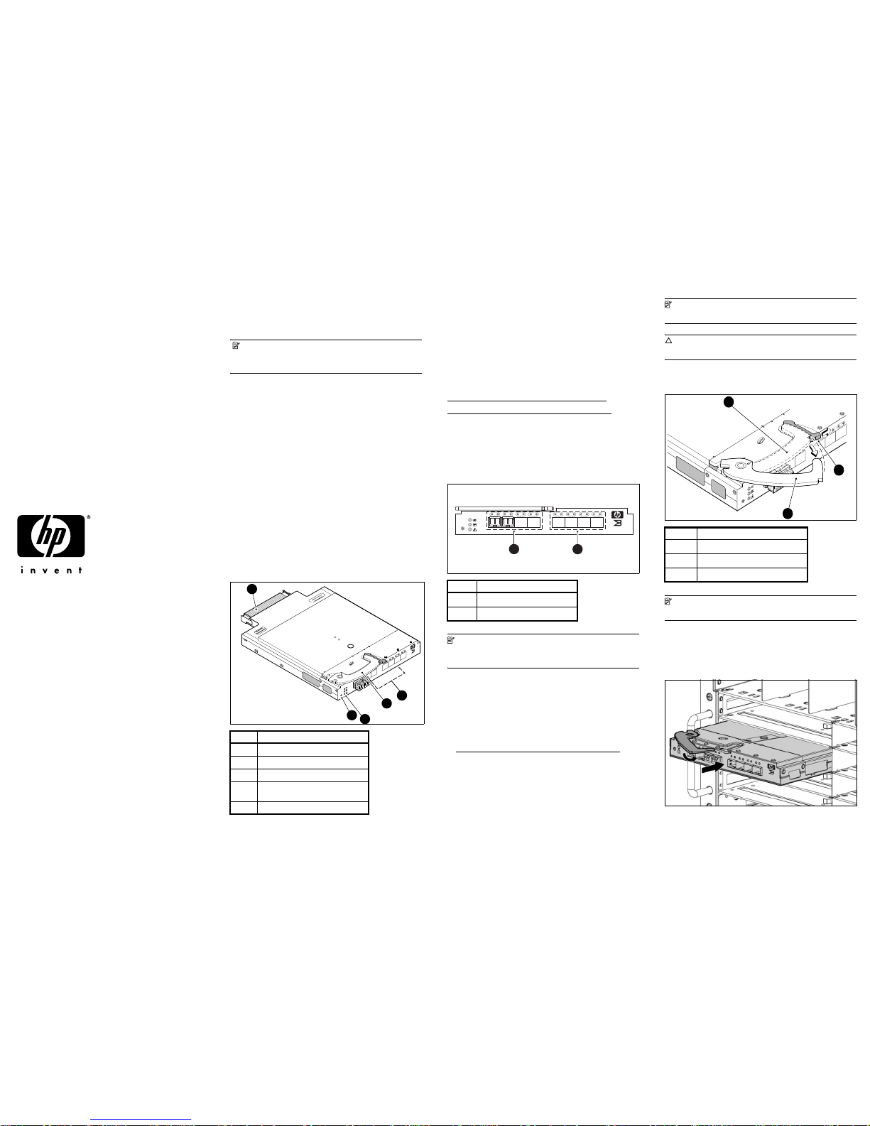
Figure 1 Brocade 4Gb SAN Switch with two SFPs installed
Additional information
See the HP BladeSystem enclosure setup and installation guide
provided with your enclosure for more information on the
association between the server mezzanine bays and the
enclosure interconnect bays.
For example, where you install the mezzanine card will
determine where you need to install interconnect modules like
the Brocade 4Gb SAN Switch.
Also access additional component information:
http://www.hp.com/go/bladesystem/interconnects
http://www.hp.com/go/bladesystem/documentation
4Gb SAN Switch connection
identification
Figure 2 shows the external ports for the Brocade 4Gb SAN
Switch.
Figure 2 Exter nal ports
NOTE: Refer to the HP BladeSystem enclosure setup and
installation guide provided with your enclosure for specific
information on BladeSystem enclosure internal port mapping.
Install the 4Gb SAN Switch
Install the Brocade 4Gb SAN Switch into the enclosure.
1. For help identifying your specific enclosure setup and
available connections, obtain the HP BladeSystem enclosure
setup and installation guide provided with your enclosure, or
access from:
http://www.hp.com/go/bladesystem/documentation
2. Locate the appropriate interconnect bay in the rear of the
enclosure per the HP BladeSystem enclosure setup and
installation guide.
NOTE: Populate all enclosure interconnect bays with
either a switch, Pass-Thru or one of the blank panels provided.
CAUTION: Properly ground yourself before handling the
switch.
3. Press the handle latch to release the installation handle. See
Figure 3.
Figure 3 Releasing the installation handle
NOTE: The Brocade 4Gb SAN Switch is a hot-pluggable
device. The enclosure power may be on or off during install.
4. Align the Brocade 4Gb SAN Switch with the appropriate
interconnect bay according to your enclosure’s specific
configuration. Push firmly into the interconnect bay (see
Figure 4).
Figure 4 Installing the Brocade 4Gb SAN Switch into an interconnect
bay
5. Press the installation handle into the latch to lock the
Brocade 4Gb SAN Switch in place.
Item Description
1
Midplane connector
2
Eight external FC ports
3
Installation handle
4
Unit ID (UID), Health LED, and Status
LEDs
5
Reset butto n
scale: 3/8" = 1"
21 22
23
0
17 18 19
20
!
80-100074-01 Rev
.C
WH0 40000211
MAC 00 05 1E 35 A2 D6
WWN 10:00:0
0:05:1E:35:A2:D6
Reset
4Gb SAN Switch
BROCAD
E
3
1
5
4
2
Item Description
1
Left bank – ports 17, 18, 19, 20
2
Right bank – ports 21, 22, 23,0
scale: .667" = 1"
21 22 23 017 18 19 20
!
Reset
4Gb SAN Switch
BROCADE
25074a
1
2
Item Description
1
Installation handle in latched position
2
Handle latch
3
Installation handle (released)
scale: 2/3" = 1"
21
22
23
17
18
19
20
!
Reset
25071a
2
3
1
4Gb SAN Switch
BROCADE
Brocade 4Gb SAN Switch
for HP c-Class BladeSystem
installation instructions
© Copyright 2007 Hewlett-Packard Development Company, L.P.
The information contained herein is subject to change without notice.
The only warranties for HP products and services are set forth in the
express warranty statements accompanying such products and services.
Nothing herein should be construed as constituting an additional
warranty. HP shall not be liable for technical or editorial errors or
omissions contained herein.
Third edition June 2007
Printed in China
www.hp.com
Page 2
Verify configuration
The HP Onboard Administrator is the enclosure management
module used to support and manage the HP c-Class
BladeSystem and all managed devices used in the enclosure.
Once the switch is installed in the interconnect bay, the OA
verifies that the switch type matches the mezzanine cards
present on the servers. If there is no mismatch, the OA powers
up the switch.
If the switch does not power up, check the enclosure and switch
status using the OA web interface. Refer to HP BladeSystem
Onboard Administrator user guide.
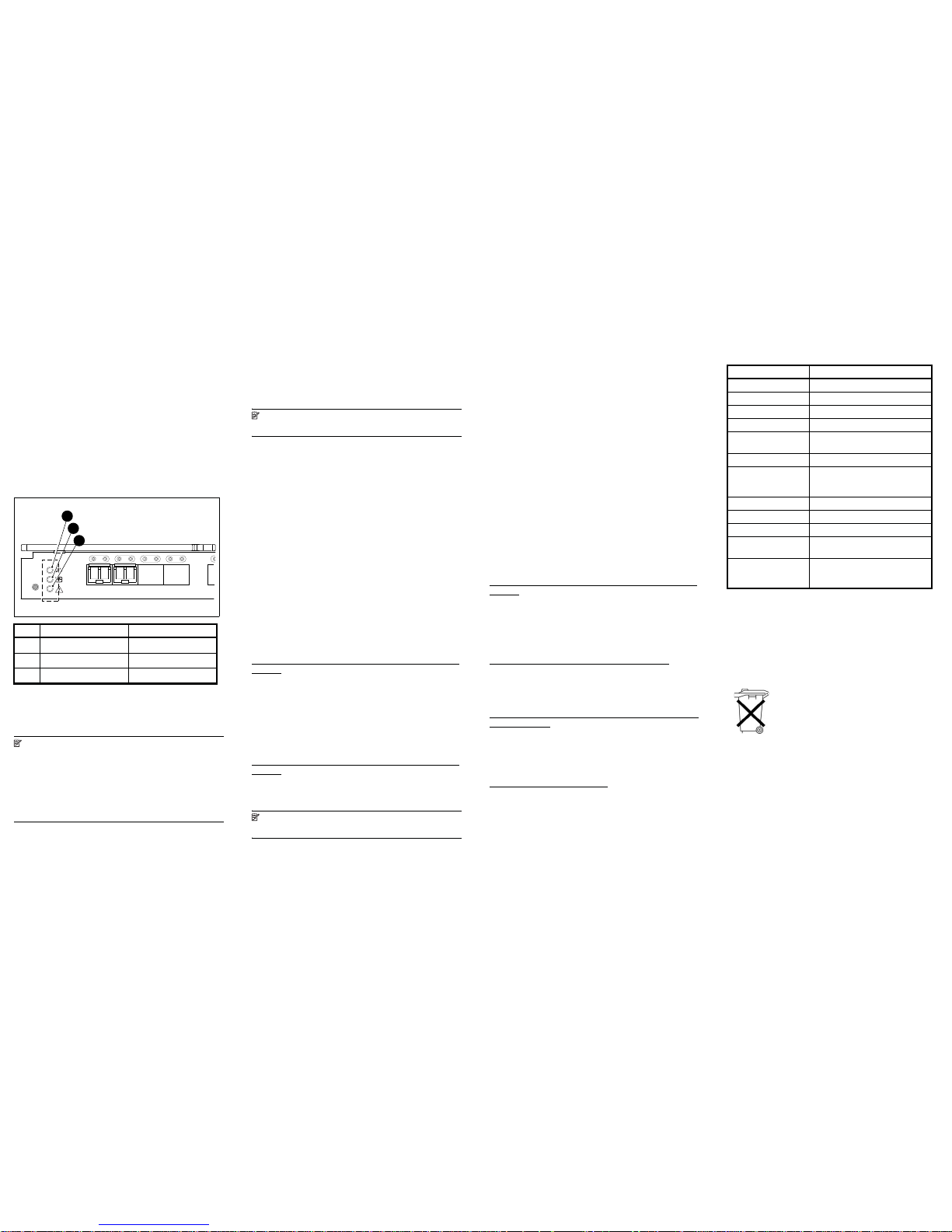
Check LEDs
Locate LEDs as shown in Figure 5. Check LEDs per the
indicators described in the following table.
Figure 5 Identifying LEDs
Set the switch Ethernet
IP address
NOTE: The switch supports DHCP beginning with
v5.2.1b firmware. For switch rev C or greater (see case label),
DHCP is enabled by default, simplifying multiple switch
installations.
To enable or disable this feature, login with these default
credentials and issue the ipaddrset command :
username: admin
password: password
To set the Ethernet IP address:
1. Verify that the enclosure is powered on.
2. Verify that the switch is installed.
3. Choose one of the following methods to set the Ethernet IP address:
• Using Enclosure Bay IP Addressing (EBIPA)
•Using External DHCP
• Setting the IP address manually
Using Enclosure Bay IP Addressing (EBIPA)
To set the Ethernet IP address using EBIPA:
1. Connect to the active OA via a web browser.
2. Enable EBIPA for the corresponding interconnect bay.
3. Click t he Apply button to restart the switch.
4. Verify the IP address using a telnet or ssh login to the switch, or by
selecting the switch in the OA GUI Rack Overview window.
NOTE: Refer to the HP BladeSystem Onboard
Administrator User Guide for additional information on EBIPA.
Using External DHCP
To set the Ethernet IP address using external DHCP:
1. Connect to the active OA via a web browser.
2. Document the DHCP-assigned address by selecting the switch from
the GUI Rack Overview window.
3. Verify the IP address using a telnet or ssh login to the switch, or by
selecting the switch in the OA GUI Rack Overview window.
Setting the IP address manually
To set the IP address manually:
1. If switch IP address is known, log into the switch with telnet or ssh
Or
2. Log into the active OA via telnet, ssh, or serial null modem cable.
a. Use the connect interconnect command (documented in
the OA User Guide) to connect to the switch bay and log into
the switch.
3. Apply a static IP address to the switch using the ipaddrset
command. Refer to the Brocade 4Gb SAN Switc h for HP c-Cla ss
BladeSystem user guide for specific procedures. Access from the
Brocade 4Gb SAN Switch product web page:
http://www.hp.com/go/storageworks/4gbswitchforc-classbla
desystem
4. Verify the IP address as described above.
Firmware update
To achieve best performance, HP recommends running the
latest firmware re lease. O btain the mo st current Fabric OS
firmware, configuration files and MIB files that support this
switch from the following HP we b site:
http://www.hp.com/go/storageworks/4gbswitchforc-classbla
desystem
To download firmware from the web to another computer (like
an FTP server):
NOTE: Web retrieval procedures may be subject to
change.
1. Go to the Support section, located on the far right side of
the web page. Click Software & drivers.
2. Lo cate t he Tasks for Brocade 4Gb SAN Switch for
HP c-Class BladeSystem section.
3. Cli ck Download drivers and software.
a. Select the applicable switch model.
b. Go to the Select Operating System section. Click Cross
operating system (BIOS, Firmware,
Diagnostics, etc.)
c. Scroll down to the firmware section of the web page and
locate the Firmware table.
d. Locate the latest firmware.
e. Click Download button>> in the last column and
follow the prompts in the File Download dialog box.
4. To download the code from an FTP server to the switch,
connect an Ethernet cable from the FTP server to the iLO
RJ45 on the active OA.
5. Telnet to the switch and issue firmwaredownload at the
command line.
Configure the Brocade 4Gb
SAN Switch
Set Brocade 4Gb SAN Switch parameters via the following
management tools:
• Command Line Interface (CLI)
• Advanced Web Tools Graphical User Interface (GUI)
Refer to the Brocade 4Gb SAN Switch for HP c-Class
BladeSystem user guide for specific procedures. Access from
the Brocade 4Gb SAN Switch product web page:
h
ttp://www.hp.com/go/storageworks/4gbswitchforc-classbla
desystem
Related documentation
The most current documentation for interconnects and other HP
BladeSystem c-Class components is available at the following
web site :
http://www.hp.com/go/bladesystem/documentation
In addition, refer to the HP StorageWorks SAN Design
referenc e guide for HP Storage Area Network (SAN)
configuration guidelines:
http://h18000.www1.hp.com/products/storageworks/san/d
ocumentation.html
Access future product updates
HP strongly recommends that customers sign up online using
the Subscri ber's choic e web site :
http://www.hp.com/go/e-updates
Subscribing to this service provides you with e-mail updates on
the latest product enhancements, newest versions of drivers,
and firmware documentation updates as well as instant access
to numerous other product resources.
Quick specs
The following table lists Brocade 4Gb SAN Switch technical
specifications.
Waste Electrical and Electronic
Equipment (WEEE)
Recycling Notice
Disposal of waste equipment by users in private households in
the European Union
Item Description Indicators
1
UID LED Off
2
Health ID LED Steady green light
3
Module Status LED Steady green light
scale: 1" = 1"
17 18 19 20
!
Reset
25075a
1
2
3
Specification Description
Height 29.3 mm (1.15 in)
Depth 280 mm (11.02 in)
Width 208 mm (8.19 in)
Weight 1.27 kg (2.8 lb)
Temperature range
during operation
10
° to 35°C
(50
° to 95°F)
Air flow Normal: p rovided by enclosure
Media types Hot-pluggable, industry-standard SFPs;
Short-wave Laser (SWL),
up to 500 m (1,640 ft.)
Configurable port types F_Port, FL_Port, and E_Port
System architecture Non-blocking shared memory switch
Modes of operation FC Class 2, Class 3 Class F
Port-to-port latency Less than 2 microseconds with no
contention (destination port is free)
Power 35 Watts; Provided by the HP
BladeSystem enclosure. No other
power requirement or provision exists.
This symbol on the product or on its
packaging indicates that this product
must not be disposed of with your other
household waste. Instead, it is your
responsibility to dispose of your waste
equipment by handing it over to a
designated collection point for the
recycling of waste electrical and
electronic equipment. The separate
collection and recycling of your waste
equipment at the time of disposal will
help to conserve natural resources and
ensure that it is recycled in a manner that
protects human health and the
environment. For more information about
where you can drop off your waste
equipment for recycling, please contact
your local city office, your household
waste disposal service or the shop where
you purchased the product.
 Loading...