


Upgrade Guide
HP Brio PCs BA & BAx
http://www.hp.com/go/briosupport

Notice
Notice
The information contained in this document is subject to change without notice.
Hewlett-Packard makes no warranty of any kind with regard to this material,
including, but not limited to, the implied warranties of merchantability and fitness
for a particular purpose. Hewlett-Packard shall not be liable for errors contained
herein or for incidental or consequential damages in connection with the furnishing,
performance, or use of this material.
This document contains proprietary information that is protected by copyright. All
rights are reserved. No part of this document may be photocopied, reproduced, or
translated into another language without the prior written consent of HewlettPackard Company.
Microsoft®, MS-DOS® and Windows® are U.S. registered trademarks of Microsoft
Corporation.
Hewlett-Packard France
Commercial Computing Division
Customer Satisfaction
5, avenue Raymond Chanas - Eybens
38053 Grenoble Cedex 9
France
© 1999 Hewlett-Packard Company
ii

Notice ..............................................................................................................................................ii
1 Replacing Inside the Computer....................................................... 5
Inside the Computer ............................................................................................................... 6
2 Replacing the Cover........................................................................... 7
Removing the Cover ............................................................................................................... 8
Replacing the Cover .............................................................................................................10
3 Replacing the System Board............................................................ 11
Removing the System Board .............................................................................................12
Replacing the System Board .............................................................................................15
4 Replacing the Floppy Drive............................................................. 17
Removing the Floppy Drive ...............................................................................................18
Replacing the Floppy Disk Drive .....................................................................................19
5 Replacing the Hard Disk Drive ....................................................... 21
Removing the Hard Disk Drive .........................................................................................22
Replacing the Hard Disk Drive .........................................................................................24
6 Replacing a 5.25" Bay Disk Drive ................................................. 25
Installing an Expansion Bay Drive .................................................................................26
Removing an Expansion Bay Drive ............................................................................... 30
7 Replacing a Memory Module......................................................... 33
Installing a Memory Module ............................................................................................34
Removing a Memory Module ...........................................................................................36
iii

8 Replacing the Video RAM............................................................... 37
Replacing the VRAM Module ...........................................................................................38
9 Replacing Expansion Cards............................................................ 41
Installing an Expansion Card ...........................................................................................42
Removing an Expansion Card .........................................................................................43
10 Replacing the Power Supply Unit................................................. 45
11 Replacing the Processor................................................................. 49
iv

Inside the Computer
1
5
Replacing Inside the Computer
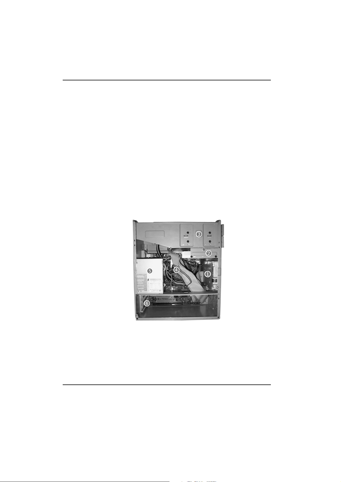
Inside the Computer
Inside the Computer
The following components are inside your computer.
1 Hard disk drive bay
2 Floppy disk drive bay
3 5.25" drive expansion bays
4System board
5 Power supply unit
6 Expansion card bay
6

Replacing...
the Cover
2
7
Replacing the Cover
Removing the Cover
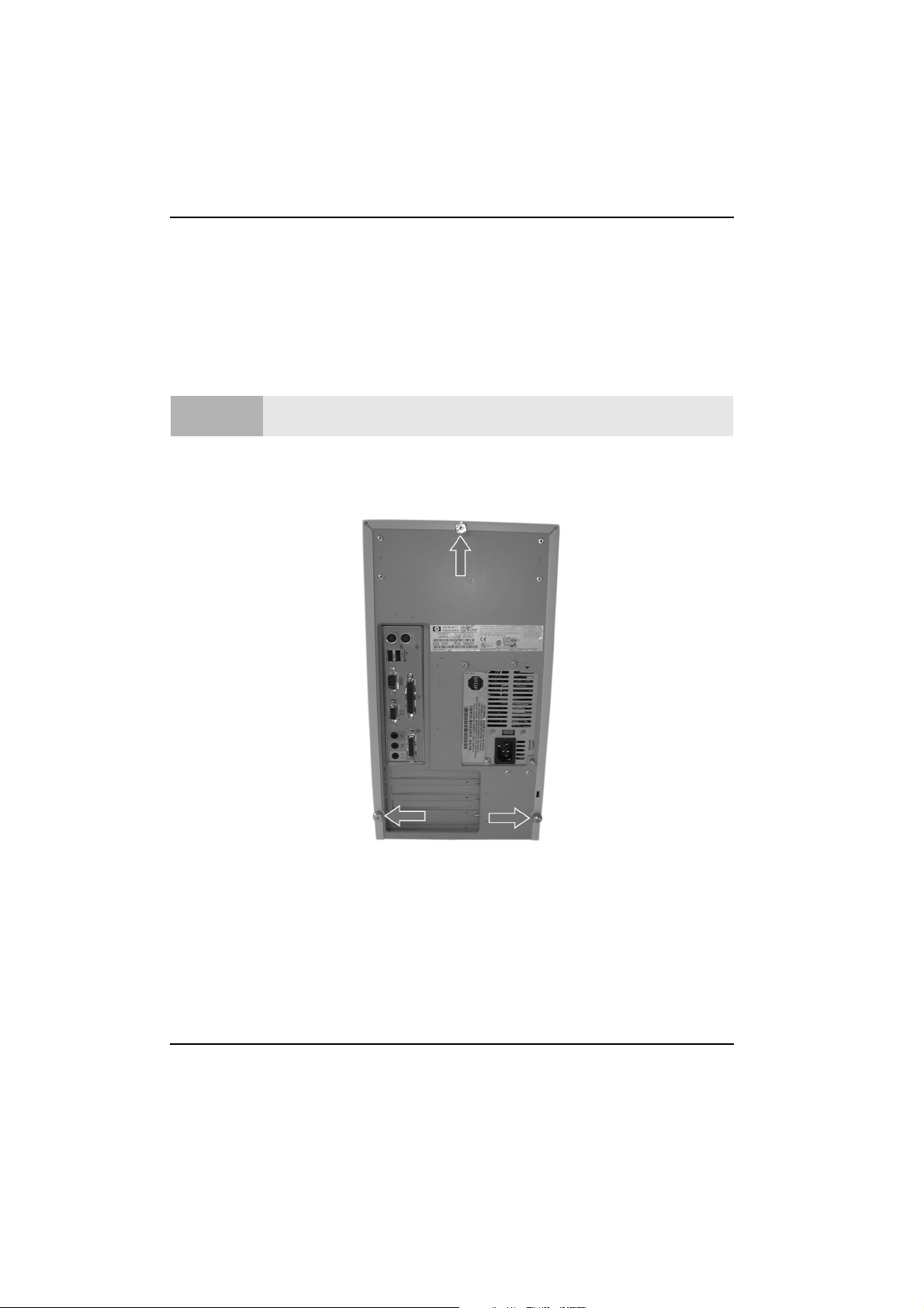
Removing the Cover
You will need a flat area, such as a table, to rest the computer on.
Caution
1 Disconnect all of the cables from the computer.
2 Remove the three screws on the back of the computer by unscrewing them
with your hand.
For your safety, disconnect the power cord and all external cables.
8
Replacing the Cover
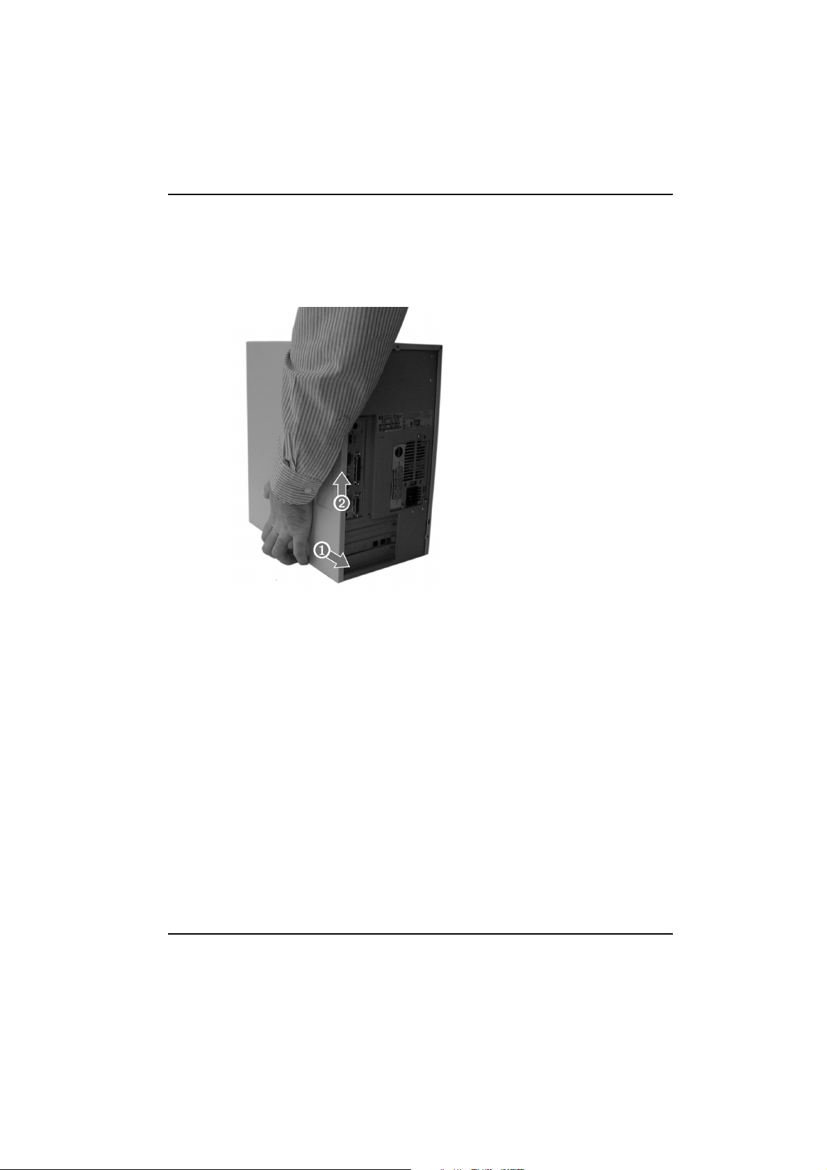
3 Pull the cover towards the back ➊of the computer and up ➋.
Removing the Cover
9
Replacing the Cover
Replacing the Cover
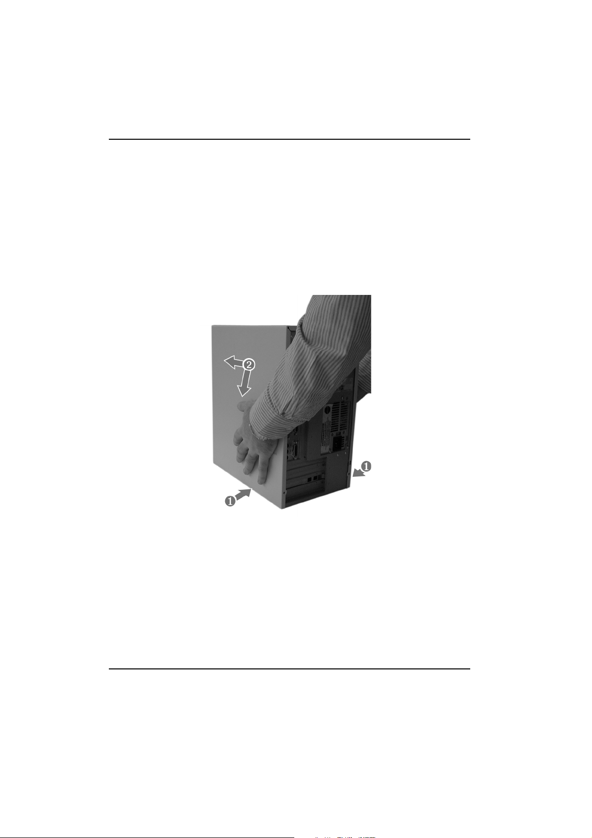
Replacing the Cover
1 Place the cover over the computer
2 Push the computer cover inwards ➊,and then down and forward ➋, making
sure that the guides at the bottom of the computer are engaged and that the
case is correctly seated.
3 Replace the three screws on the back of the computer. Refer to step 2 on
page 8.
10

Replacing...
the System Board
3
11
Replacing the System Board
Removing the System Board
Removing the System Board
If your old system board contains a lithium battery, do not dispose of it in
household waste. Please return batteries to the shop from which you bought
Warning
them, to the dealer from whom you purchased your PC, or to HP, so they can be
recycled or disposed of in a sound way. Returned used batteries will be
accepted free of charge.
Caution
For your safety, disconnect the power cord and all external cables.
You will need:
• to have removed the cover. Refer to “Removing the Cover” on page 8.
• to have a Torx T-15 or a slotted screw driver.
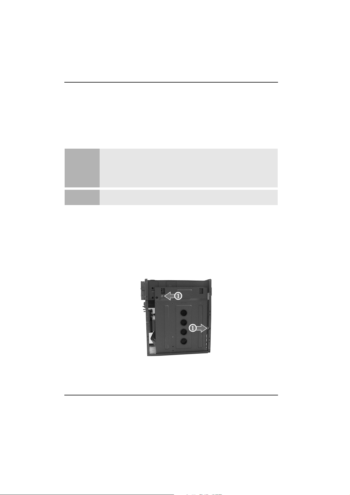
The Procedure
1 Remove the two screws ➊.
12
Replacing the System Board
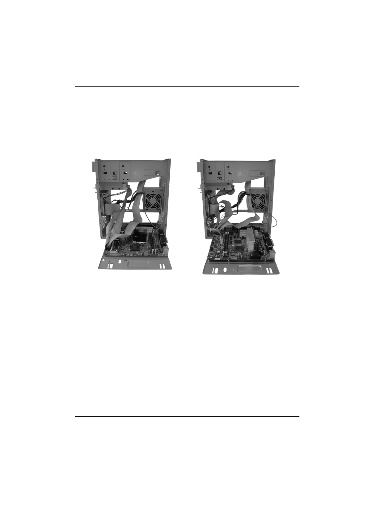
Removing the System Board
2 Pull the system board down from the top until it is laying flat, as in one of the
pictures below.
3 Remove all cables from the board.
13
Replacing the System Board
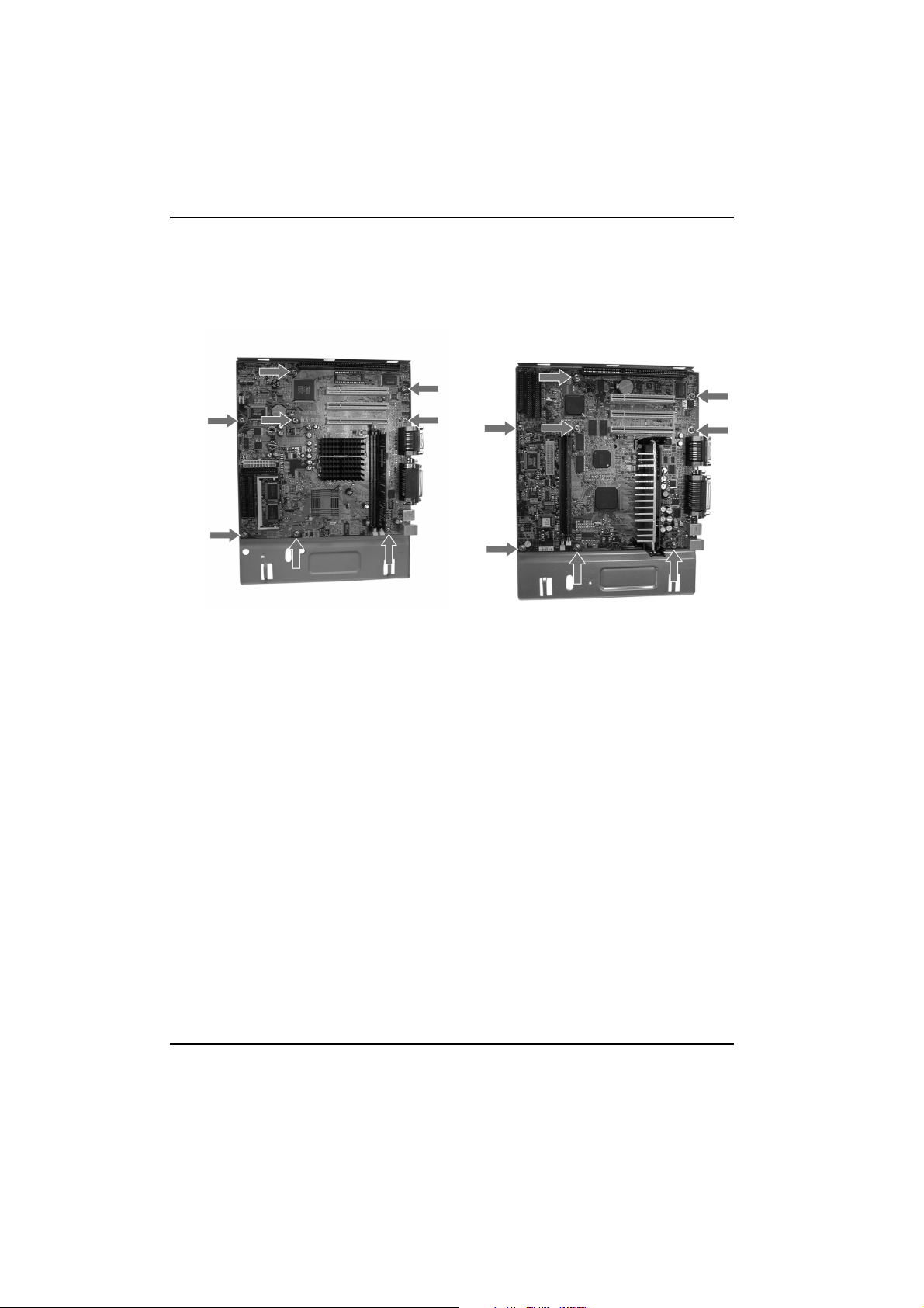
Removing the System Board
4 Remove the eight screws.
5 Lift the system board out of the computer.
6 Remove any exchangeable components, such as the processor, memory
modules or video memory modules. Refer to the appropriate chapters for
instructions on removing the individual components.
14
Replacing the System Board
Replacing the System Board
Replacing the System Board
You will need:
• to make sure that the replacement board has all jumpers set to the same as
the system board that is being replaced.
• to make sure that the any components removed from the system board being
replaced are inserted in the new board. Refer to the appropriate chapters for
instructions on inserting the individual components.
The Procedure
1 Place the system board onto its base.
2 Replace the eight screws. Refer to step 4 on page 14 for the location of the
screws.
3 Replace the cables into their appropriate sockets. The connectors are keyed
and can only fit into the sockets in one direction.
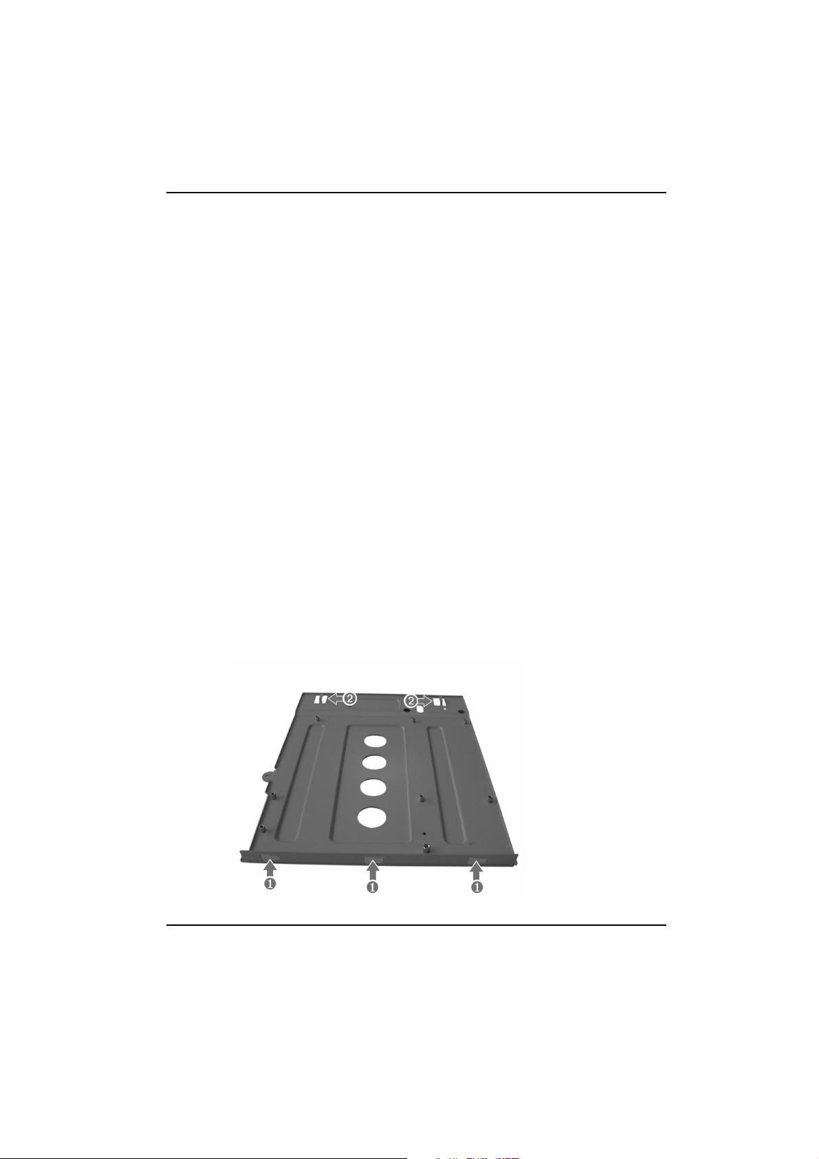
4 Replace the system board into the computer, making sure that the bottom
mounts ➊ are correctly inserted into the bottom of the case and that the top
mounts ➋ are correctly engaged.
15

Replacing the System Board
Replacing the System Board
5 Slide the system board towards the front of the computer.
6 Replace the screws.
7 Replace the cover.
16

Replacing...
the Floppy Drive
4
17

Replacing the Floppy Drive
Removing the Floppy Drive
Removing the Floppy Drive
You will need to have removed the cover. Refer to “Removing the Cover” on page 8.
Caution
1 Undo the floppy drive bay fixing screw.
2 Pull the bay towards the back of the computer until it is released from its
mountings.
3 Undo the four screws ➊, two on each side.
For your safety, disconnect the power cord and all external cables.
4 Remove the two cables form the back of the drive.
5 Slide the drive out of the bay.
18

Replacing the Floppy Drive
Replacing the Floppy Disk Drive
Replacing the Floppy Disk Drive
1 Slide the drive into the drive bay, making sure that the connectors on the
rear of the drive are at the back of the bay.
2 Replace the two drive cables.
3 Replace the four screws. Refer to step 3 on page 18 for the location of the
screws.
4 Slide the drive into the computer, making sure that the slots ➊ are located
on the tags ➋.
5 Replace the floppy drive bay fixing screw.
6 Replace the cover.
19

Replacing the Floppy Drive
Replacing the Floppy Disk Drive
20

Replacing...
5
the Hard Disk Drive
This chapter explains how to remove and replace the hard disk
drive. If you wish to install or replace a second hard drive, then
you must refer to the chapter “Replacing a 5.25" Bay Disk
Drive” on page 25.
21

Replacing the Hard Disk Drive
Removing the Hard Disk Drive
Removing the Hard Disk Drive
You will need to have removed the cover. Refer to “Removing the Cover” on page 8.
Caution
1 Remove the hard drive bay fixing screw.
For your safety, disconnect the power cord and all external cables.
2 Slide the drive bay towards the cables until the bay is out of its mounts, and
then pull the drive out of the computer.
22

Replacing the Hard Disk Drive
Removing the Hard Disk Drive
3 Remove the power ➊ and data ➋ cables from the hard disk drive.
4 Undo the four screws ➊.
5 Slide the hard disk drive out of the bay.
23

Replacing the Hard Disk Drive
Replacing the Hard Disk Drive
Replacing the Hard Disk Drive
1 Slide the drive into the hard drive bay making sure that the drive is correctly
mounted.
2 Fit the four screws. Refer to step 4 on page 23 for the screw positions.
3 Replace the power and data cables. Refer to step 1 on page 22 for the cable
positions.
4 Replace the bay into the computer, making sure that the tags are correctly
engaged in their holes.
5 Replace the bay fixing screw.
6 Replace the cover.
24

Replacing...
6
a 5.25" Bay Disk Drive
This chapter explains how to remove and install drives into the two 5.25"
drive bays. These bays can hold CD-ROM, DVD, Hard Disk or Zip drives. If you
wish to replace the hard disk drive that came pre-installed in your computer,
then refer to the chapter “Replacing the Hard Disk Drive” on page 21.
25

Replacing a 5.25" Bay Disk Drive
Installing an Expansion Bay Drive
Installing an Expansion Bay Drive
You will need to have removed the cover. Refer to “Removing the Cover” on page 8.
For your safety, disconnect the power cord and all external cables. When
installing a CDROM drive, to avoid electric shock and damage to your eyes by
Caution
Your computer has two drive bays. One of the drive bays may already be occupied.
The instructions below explain how to instal a drive into either the top or the bottom
bay.
1 Decide on which bay you wish to use.
2 If the bay you wish to use is the bottom bay, or you wish to use the top bay
and it is empty, then remove the front of the computer by first releasing the
two clips on the top of the computer. Otherwise go to step 7 on page 28.
laser light, do not open the laser module. The laser module should be serviced
by service personnel only. Do not attempt to make any adjustment to the laser
unit. Refer to the label on the CDROM for power requirements and wavelength.
26

Replacing a 5.25" Bay Disk Drive
Installing an Expansion Bay Drive
3 Release the two clips on either side of the computer.
4 Lay the front cover down in front of the computer, taking care of the cables
that connect to the system board.
5 Remove the plastic drive blanking plate by pushing the clips outwards and
then lifting the plate out.
27

Replacing a 5.25" Bay Disk Drive
Installing an Expansion Bay Drive
6 If the bay has a metal blanking plate, then break it off using a screw driver.
7 If the bottom bay is to be used, then slide the drive in from the front of the
computer. Otherwise slide the drive in from the rear.
8 Fit the four screws, two on each side as shown below. ➊ shows the position
of the top bay screws and ➋ for the bottom (these are shown with the
system board removed. It is not necessary to remove the system board).
28

Replacing a 5.25" Bay Disk Drive
Installing an Expansion Bay Drive
9 Connect the audio ➊ (only if you install a CDROM or DVD drive), data ➋ and
power ➌ drive cables.
10 Replace the cover. Refer to “Replacing the Cover” on page 10.
29

Replacing a 5.25" Bay Disk Drive
Removing an Expansion Bay Drive
Removing an Expansion Bay Drive
You will need to have removed the cover. Refer to “Removing the Cover” on page 8.
1 If you are removing a drive from the bottom drive bay then remove the front
of the computer by first releasing the two clips on the top of the computer.
Otherwise go to step 5 on page 31.
2 Release the two clips on either side of the computer.
30

Replacing a 5.25" Bay Disk Drive
Removing an Expansion Bay Drive
3 Lay the front cover down in front of the computer, taking care of the cables
that connect to the system board.
4 If you are not going to use the bay after removing the drive, then place a
plastic blanking plate into the cover if one is available.
5 Remove the drive cables. Refer to step 9 on page 29 for the location of the
cables.
6 Remove the four screws from the drive. Refer to step 8 on page 28 for the
location of the screws.
7 If the drive is in the bottom bay, then slide the drive out from the front of the
computer. Otherwise slide the drive out from the rear.
8 Replace the cover. Refer to “Replacing the Cover” on page 10.
31

Replacing a 5.25" Bay Disk Drive
Removing an Expansion Bay Drive
32

Replacing...
a Memory Module
7
33

Replacing a Memory Module
Installing a Memory Module
Installing a Memory Module
Caution
For your safety, disconnect the power cord and all external cables.
You will need:
• to have removed the cover. Refer to “Removing the Cover” on page 8.
• to have removed the system board. Refer to “Removing the System Board”
on page 12. You do not need to remove the cables from the system board, as
in step 3 on page 13.
The Procedure
1 Locate an empty memory module socket.
2 Make sure that the socket’s clips are open.
3 Holding the memory module by its longest edges, slide it into the socket. It is
keyed and can only go in to the socket in one direction.
34

Replacing a Memory Module
Installing a Memory Module
4 Push down the memory module until the clips are closed.
5 Replace the system board. Refer to “Replacing the System Board” on page
15.
6 Replace the cover. Refer to “Replacing the Cover” on page 10.
35

Replacing a Memory Module
Removing a Memory Module
Removing a Memory Module
Caution
For your safety, disconnect the power cord and all external cables.
You will need:
• to have removed the cover. Refer to “Removing the Cover” on page 8.
• to have removed the system board. Refer to “Removing the System Board”
on page 12. You do not need to remove the cables from the system board, as
in step 3 on page 13.
The Procedure
1 Locate the memory module that you wish to remove.
2 Open both clips at each end of the module. Refer to step 2 on page 34.
3 Holding the memory module by its longest edges, pull it up and out of the
socket.
4 Replace the system board. Refer to “Replacing the System Board” on page
15.
5 Replace the cover. Refer to “Replacing the Cover” on page 10.
36

Replacing...
8
the Video RAM
You only need to replace the VRAM (Video RAM) in the HP Brio PC BA
model.
37

Replacing the Video RAM
Replacing the VRAM Module
Replacing the VRAM Module
Caution
For your safety, disconnect the power cord and all external cables.
You will need:
• to have removed the cover. Refer to “Removing the Cover” on page 8.
• to have removed the system board. Refer to “Removing the System Board”
on page 12. You do not need to remove the cables from the system board, as
in step 3 on page 13.
The Procedure
1 Locate the VRAM module.
38

Replacing the Video RAM
Replacing the VRAM Module
2 Push the two clips outwards.
3 Holding the module by its longest edges, lift it up and out of the socket.
4 Slide the new module into the socket, making sure that the side with the IC’s
is uppermost.
5 Push the module down until it is properly seated.
6 Replace the system board. Refer to “Replacing the System Board” on page
15.
7 Replace the cover. Refer to “Replacing the Cover” on page 10.
39

Replacing the Video RAM
Replacing the VRAM Module
40

Replacing...
Expansion Cards
9
41

Replacing Expansion Cards
Installing an Expansion Card
Installing an Expansion Card
You will need to have removed the cover. Refer to “Removing the Cover” on page 8.
Caution
1 Locate a free socket. If the card is an ISA card, then it must be located in the
long black socket, otherwise the card is located in the shorter, white sockets.
2 Remove the blanking plate for the socket by moving the fixing screw and
then pulling the plate up and out of the socket.
For you safety, disconnect the power cord and all external cables.
3 Push the card into the socket, making sure that it is firmly seated.
4 Replace the screw.
5 Replace the cover. Refer to “Replacing the Cover” on page 10.
42

Replacing Expansion Cards
Removing an Expansion Card
Removing an Expansion Card
You will need to have removed the cover. Refer to “Removing the Cover” on page 8.
Caution
1 Locate the expansion card.
2 Remove the expansion card’s fixing screw. Refer to step 2 on page 42.
3 Place a blanking plate in the computer if available.
4 Replace the fixing screw.
5 Replace the cover. Refer to “Replacing the Cover” on page 10.
For you safety, disconnect the power cord and all external cables.
43

Replacing Expansion Cards
Removing an Expansion Card
44

Replacing...
10
the Power Supply Unit
45

Replacing the Power Supply Unit
Removing the Power Supply Unit
You will need to have removed the cover. Refer to “Removing the Cover” on page 8.
Caution
1 Looking at the back of the computer, remove the three screws shown below.
2 Disconnect all power cables from the various drives and system board.
3 Slide the power supply unit up and out of the computer.
For your safety, disconnect the power cord and all external cables.
Replacing the Power Supply Unit
1 Reconnect all the power cables to the drives and the system board.
2 Place the new Power Supply Unit inside the computer, making sure that the
socket faces the back of the computer and that the cables are inside the
computer.
3 Replace the three screws. Refer to step 1 on page 46.
4 Replace the cover.
46

Replacing the Power Supply Unit
5 Check that the switch voltage of the PSU is set to the correct value for the
country that you are in.
47

Replacing the Power Supply Unit
48

Replacing...
11
the Processor
Details on how to replace the Processor (or CPU — central processing unit),
can be found in,
• your Online Reference Guide, "Upgrading a Processor", or,
• www.hp.com/go/briosupport
49

Replacing the Processor
50


Paper not bleached with chlorine
Part Number 5967-9523
Printed in
V2
 Loading...