

Page 1

HP Integrity BL860c i4, BL870c i4 & BL890c i4 Server Blade User Service Guide
Abstract
This document contains specific information that is intended for users of this HP product.
HP Part Number: 5900-2673
Published: August 2013
Edition: 3
Page 2

© Copyright 2012, 2013 Hewlett-Packard Development Company, L.P.
The information contained herein is subject to change without notice. The only warranties for HP products and services are set forth in the express
warranty statements accompanying such products and services. Nothing herein should be construed as constituting an additional warranty. HP shall
not be liable for technical or editorial errors or omissions contained herein.
Acknowledgments
Intel, Pentium, Itanium, Intel Inside, and the Intel Inside logo are trademarks or registered trademarks of Intel Corporation or its subsidiaries in the
United States and other countries. UNIX is a registered trademark of The Open Group. Microsoft and Windows are U.S. registered trademarks of
Microsoft Corporation.
Warranty
To get a copy of the warranty for this product see the warranty information website:
http://bizsupport2.austin.hp.com/bc/docs/support/SupportManual/c01865770/c01865770.pdf
Revision history
Document manufacturing
part number
Operating systems
supported
HP-UX5992-1083
HP-UX5900-2663
HP-UX5900-2673
Publication DateEdition numberSupported product
versions
December 2012FirstBL860c i4, BL870c i4 &
BL890c i4
May 2013SecondBL860c i4, BL870c i4 &
BL890c i4
August 2013ThirdBL860c i4, BL870c i4 &
BL890c i4
Page 3

Contents
1 Overview..................................................................................................7
Server blade overview...............................................................................................................7
Server blade components..........................................................................................................8
2 Site preparation.........................................................................................9
Server blade dimensions and weight...........................................................................................9
Enclosure information................................................................................................................9
Enclosure environmental specifications.........................................................................................9
Sample Site Inspection Checklist...............................................................................................10
Power subsystem.....................................................................................................................12
ESD handling information........................................................................................................12
Unpacking and inspecting the server blade................................................................................12
Verifying site preparation....................................................................................................13
Inspect the shipping containers for damage...........................................................................13
Unpacking the server blade................................................................................................13
Verifying the inventory........................................................................................................13
Returning damaged equipment............................................................................................13
3 Installing the server blade into the enclosure................................................14
Installation sequence and checklist............................................................................................14
Installing and powering on the server blade...............................................................................14
Preparing the enclosure......................................................................................................14
Removing a c7000 device bay divider.............................................................................15
Removing a c3000 device bay mini-divider or device bay divider........................................16
Installing interconnect modules........................................................................................17
Interconnect bay numbering and device mapping.........................................................18
Installing the server blade into the enclosure..........................................................................19
Server blade power states...................................................................................................20
Powering on the server blade..........................................................................................21
Powering off the server blade..........................................................................................21
Installing the Blade Link for BL860c i4, BL870c i4 or BL890c i4 configurations...............................21
Using iLO 3...........................................................................................................................25
Accessing UEFI or the OS from iLO 3 MP...................................................................................25
UEFI Front Page.................................................................................................................26
Saving UEFI configuration settings...................................................................................28
Booting and installing the operating system...........................................................................28
Operating system is loaded onto the server blade..................................................................28
Operating system is not loaded onto the server blade.............................................................28
OS login prompt................................................................................................................28
Installing the latest firmware using HP Smart Update Manager.....................................................29
4 Operating system procedures.....................................................................30
Operating systems supported on the server blade.......................................................................30
Installing the operating system onto the server blade...................................................................30
Installing the OS from an external USB DVD device or tape device...........................................30
Installing the OS using HP Ignite-UX.....................................................................................31
Installing the OS using vMedia............................................................................................31
Configuring system boot options...............................................................................................32
Booting and shutting down HP-UX.............................................................................................32
Adding HP-UX to the boot options list...................................................................................32
HP-UX standard boot..........................................................................................................33
Booting HP-UX from the UEFI Boot Manager.....................................................................33
Booting HP-UX from the UEFI Shell...................................................................................34
Contents 3
Page 4

Booting HP-UX in single-user mode.......................................................................................34
Booting HP-UX in LVM-maintenance mode.............................................................................34
Shutting down HP-UX..........................................................................................................34
5 Optional components................................................................................36
Partner blades........................................................................................................................36
Hot-plug SAS disk drives..........................................................................................................37
Installing internal components..................................................................................................38
Removing the access panel.................................................................................................38
Processor and heatsink module............................................................................................39
DIMMs.............................................................................................................................44
Mezzanine cards...............................................................................................................49
HP Smart Array P711m Controller.........................................................................................50
Supercap pack mounting kit...........................................................................................51
Installing the Supercap mounting bracket..........................................................................51
Installing the P711m controller board................................................................................52
Installing the Supercap Pack...........................................................................................53
Replacing the access panel.................................................................................................54
Upgrading a conjoined configuration...................................................................................54
Procedure summary.......................................................................................................54
Upgrade kit contents......................................................................................................55
Before getting started.....................................................................................................55
Supported operating systems.....................................................................................56
Minimum firmware versions........................................................................................56
Determining your current firmware revisions..................................................................56
Rules for server blade internal components...................................................................60
Upgrading the original server.........................................................................................61
Existing server blade check........................................................................................61
Adding resources.....................................................................................................62
Final hardware check................................................................................................68
Booting the operating system.....................................................................................69
Warranty registration................................................................................................69
Support.......................................................................................................................69
Blade link and system information parameters...................................................................70
Operating System Licenses.............................................................................................70
The Quick Boot option...................................................................................................71
Possible changes due to VC profile mapping on the upgraded blade server..........................72
FC SAN connections.................................................................................................72
FCoE SAN connections.............................................................................................73
Ethernet network connections.....................................................................................74
Preserving VC-assigned MAC addresses in HP-UX by enabling Portable Image......................75
Pre-Upgrade Procedure for PI.....................................................................................76
Post-Upgrade Procedure for PI....................................................................................76
6 Troubleshooting........................................................................................78
Methodology.........................................................................................................................78
General troubleshooting methodology..................................................................................78
Executing recommended troubleshooting methodology ..........................................................80
Basic and advanced troubleshooting tables...........................................................................81
Troubleshooting tools..............................................................................................................84
Controls and ports.............................................................................................................85
Front panel view...........................................................................................................85
Rear panel view............................................................................................................85
Server blade LEDs..............................................................................................................85
Front panel LEDs...........................................................................................................86
SAS disk drive LEDs.......................................................................................................87
4 Contents
Page 5

SAS hard drive LED combinations...............................................................................87
Blade Link LEDs.............................................................................................................89
Virtual Front Panel LEDs in the iLO 3 TUI................................................................................89
SUV Cable and Ports..........................................................................................................91
Connecting to the serial port...........................................................................................91
Diagnostics.......................................................................................................................92
General diagnostic tools.....................................................................................................92
Fault management overview................................................................................................92
HP-UX Fault management....................................................................................................92
Errors and error logs...............................................................................................................93
Event log definitions...........................................................................................................93
Event log usage.................................................................................................................93
iLO 3 MP event logs...........................................................................................................94
SEL review........................................................................................................................95
Troubleshooting processors......................................................................................................96
Processor installation order..................................................................................................96
Processor module behaviors................................................................................................96
Enclosure information..............................................................................................................96
Cooling subsystem..................................................................................................................96
Firmware...............................................................................................................................96
Identifying and troubleshooting firmware issues......................................................................97
Verify and install the latest firmware.....................................................................................97
Troubleshooting the server interface (system console)...................................................................97
Troubleshooting the environment...............................................................................................97
7 Removing and replacing components..........................................................99
Server blade components list....................................................................................................99
Preparing the server blade for servicing...................................................................................102
Powering off the server blade............................................................................................102
Blade Link for BL870c i4 or BL890c i4 configurations...........................................................102
Removing the Blade Link for BL870c i4 or BL890c i4 configurations...................................102
Replacing the Blade Link for BL870c i4 or BL890c i4 configurations...................................103
Blade Link for BL860c i4 configurations..............................................................................104
Server blade........................................................................................................................106
Access panel.......................................................................................................................106
Disk drive blanks..................................................................................................................107
Removing a disk drive blank..............................................................................................107
Disk drives...........................................................................................................................107
DIMM baffle........................................................................................................................108
DIMMs................................................................................................................................109
CPU baffle...........................................................................................................................110
CPU and heatsink module.....................................................................................................111
SAS backplane....................................................................................................................114
Server battery......................................................................................................................114
Mezzanine cards..................................................................................................................115
ICH mezzanine board...........................................................................................................116
System board.......................................................................................................................116
Blade Link............................................................................................................................117
8 Support and other resources....................................................................119
Contacting HP......................................................................................................................119
Before you contact HP......................................................................................................119
HP contact information.....................................................................................................119
Subscription service..........................................................................................................119
Documentation feedback..................................................................................................119
HP Insight Remote Support Software...................................................................................120
Contents 5
Page 6

New and changed information in this edition...........................................................................120
Typographic conventions.......................................................................................................120
Standard terms, abbreviations, and acronyms...............................................122
A RAID configuration and other utilities........................................................125
Configuring a Smart Array Controller......................................................................................125
Using the saupdate command...........................................................................................125
get_mode..................................................................................................................125
set_mode...................................................................................................................126
Updating the firmware using saupdate...........................................................................127
Determining the Driver ID and CTRL ID................................................................................127
Configuring RAID volumes using the ORCA menu-driven interface...............................................128
Creating a logical drive....................................................................................................129
Deleting a logical drive....................................................................................................130
Useful UEFI command checks............................................................................................131
UEFI...................................................................................................................................132
UEFI Shell and HP POSSE commands.................................................................................132
Drive paths in UEFI...............................................................................................................135
Using the Boot Maintenance Manager....................................................................................135
Boot Options...................................................................................................................136
Add Boot Option........................................................................................................136
Delete Boot Option......................................................................................................137
Change Boot Order....................................................................................................138
Driver Options.................................................................................................................139
Add Driver Option......................................................................................................139
Delete Driver Option....................................................................................................140
Change Driver Order...................................................................................................140
Console Configuration......................................................................................................140
Boot From File.................................................................................................................142
Set Boot Next Value.........................................................................................................142
Set Time Out Value..........................................................................................................143
Reset System....................................................................................................................143
iLO 3 MP.............................................................................................................................144
B Regulatory information............................................................................145
Turkey RoHS material content declaration.................................................................................145
Ukraine RoHS material content declaration..............................................................................145
Warranty information............................................................................................................145
Index.......................................................................................................146
6 Contents
Page 7

1 Overview
The HP Integrity BL860c i4 Server Blade is a dense, low-cost, Intel® Itanium® processor server
blade. Using a Blade Link hardware assembly, multiple BL860c i4 Server Blades can be conjoined
to create dual-blade, four socket and quad-blade, eight socket variants.
The three blade configurations support the HP-UX operating system and are designed for deployment
in HP c-Class enclosures, specifically the 10U c7000 and the 6U c3000 Enclosures. The nPartition
configuration feature is enabled from the factory, enabling the BL870c i4 and BL890c i4 to be
partitioned into one more electrically isolated partitions. See the nPartitions Administrator Users
Guide for more information.
NOTE: For purposes of this guide, make sure that the c-Class server blade enclosure is powered
on and running properly and that the OA and iLO 3 is operational.
Server blade overview
Number of Processor SocketsNumber of Conjoined Server BladesName
21BL860c i4
42BL870c i4
84BL890c i4
PCIe I/O
Mezzanine card
capacitymax memoryDIMM slotsCPU cores (octo)Product
2416BL860c i4
16GB DIMMs
4832BL870c i4
16GB DIMMs
9664BL890c i4
DIMMs
SAS Hard Disk
Drives
23364GB with
46768GB with
8121.5TB with 16GB
Server blade overview 7
Page 8
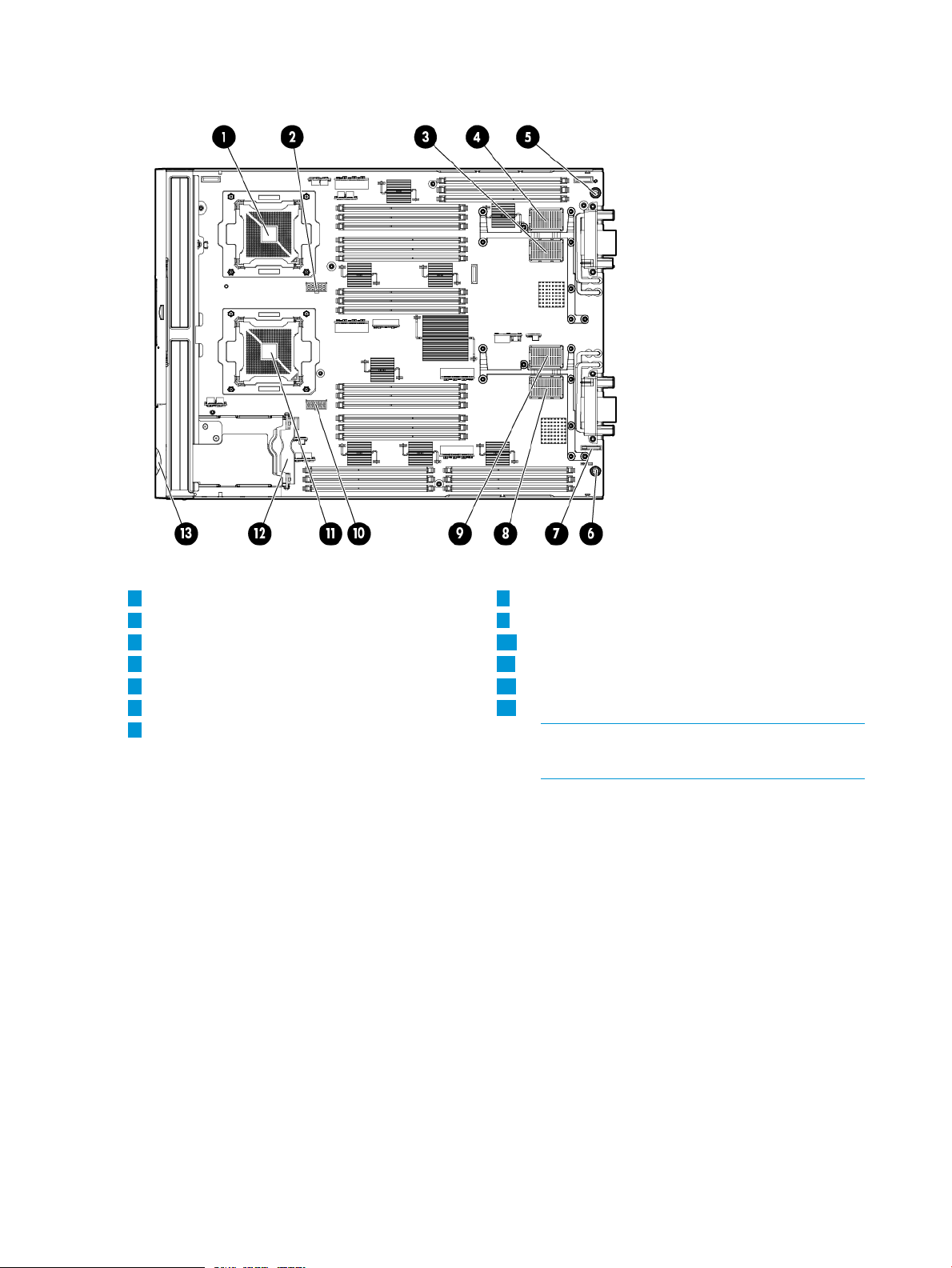
Server blade components
1
CPU0
2
CPU0 power connector
3
Mezzanine connector 1 (type 1)
4
Mezzanine connector 2 (type 1 or 2)
5
System board thumbscrew
6
System board thumbscrew
7
Battery (CR2032)
8
ICH mezzanine connector
9
Mezzanine connector 3 (type 1 or 2)
10
CPU1 power connector
11
CPU1
12
SAS backplane
13
Pull tab
NOTE: The iLO 3 password is located on
the pull tab.
8 Overview
Page 9
2 Site preparation
The HP Integrity BL860c i4 Server Blade does not have cooling or power systems. Cooling and
power is provided by the c-Class enclosure.
IMPORTANT: To avoid hardware damage, allow the thermal mass of the product to equalize to
the temperature and humidity of the installation facility after removing the shipping materials. A
minimum of one hour per 10°C (50°F) of temperature difference between the shipping facility and
installation facility is required
Server blade dimensions and weight
Table 1 Server blade dimensions and weight for the BL860c i4
valueDimensions
36.63 cm (14.42 in.)Height
5.14 cm (2.025 in.)Width
48.51 cm (19.1 in.)Depth
Weight
Unloaded: 8.6 kg (19 lb)
Fully loaded: 11.3 kg (25 lb)
Table 2 Blade Link dimensions and weight
Enclosure information
All three blade configurations are supported in HP c7000 and c3000 Enclosures.
For more enclosure information see:
http://h71028.www7.hp.com/enterprise/cache/316735-0-0-0-121.htm.
Enclosure environmental specifications
NOTE: This information is for both c3000 and c7000 Enclosures.
Temperature range
1
WeightWidthHeightBlade Link type
.5 lb (.22 kg)51 mm (2 in)44 mm (1.73 in)BL1 (BL860 i4)
1 lb (.45 kg)106 mm (4.17 in)44 mm (1.73 in)BL2 (BL870 i4)
2 lb (.90 kg)212 mm (8.34 in)44 mm (1.73 in)BL4 (BL890 i4)
ValueSpecification
Wet bulb temperature
Relative humidity (noncondensing)
10°C to 35°C (50°F to 95°F)Operating
-30°C to 60°C (-22°F to 140°F)Non-operating
28ºC (82.4ºF)Operating
38.7ºC (101.7ºF)Non-operating
2
Server blade dimensions and weight 9
Page 10

1
All temperature ratings shown are for sea level. An altitude derating of 1°C per 304.8 m (1.8°F per 1000 ft) to 3048
m (10,000 ft) is applicable. No direct sunlight allowed. Upper operating limit is 3,048 m (10,000 ft) or 70 Kpa/10.1
psia. Upper non-operating limit is 9,144 m (30,000 ft) or 30.3 KPa/4.4 psia.
2
Storage maximum humidity of 95% is based on a maximum temperature of 45°C (113°F). Altitude maximum for storage
corresponds to a pressure minimum of 70 KPa.
For more information on the c-Class enclosures, go to http://h71028.www7.hp.com/enterprise/
cache/316735-0-0-0-121.htmlf.
For more site preparation information, go to http://www.hp.com/go/Blades-docs, select HP
Integrity BL860c i4 Server Blade in the list of servers, and then select the Generalized Site Preparation
Guidelines.
Sample Site Inspection Checklist
Table 3 Customer and HP Information
Customer Information
20% to 80%Operating
5% to 95%Non-operating
Phone number:Name:
City or Town:Street address:
Zip or postal code:
Scheduled delivery date
Table 4 Site Inspection Checklist
Computer Room
Is there a completed floor plan?1.
2.
Is adequate space available for maintenance needs? Front 36
inches (91.4 cm) minimum and rear 36 inches (91.4 cm) minimum
are recommended clearances.
CountryState or province:
Phone number:Primary customer contact:
Phone number:Secondary customer contact:
Phone number:Traffic coordinator:
HP information
Order number:Sales representative
Date:Representative making survey
Comment or DateCheck either Yes or No. If No, include comment number or date.
NoYesArea or conditionNumber
4.
10 Site preparation
Is access to the site or computer room restricted?3.
Is the computer room structurally complete? Expected date of
completion?
Is a raised floor installed and in good condition?5.
Is the raised floor adequate for equipment loading?6.
Are channels or cutouts available for cable routing?7.
Page 11

Table 4 Site Inspection Checklist (continued)
Is a network line available?8.
Is a telephone line available?9.
Comment or DateCheck either Yes or No. If No, include comment number or date.
10.
12.
Power and Lighting
15a.
Are customer-supplied peripheral cables and LAN cables available
and of the proper type?
Are floor tiles in good condition and properly braced?11.
Is floor tile underside shiny or painted? If painted, judge the need
for particulate test.
Are lighting levels adequate for maintenance?13.
Are AC outlets available for servicing needs (for example, laptop)?14.
Does the input voltage correspond to equipment specifications?15.
Is dual source power used? If so, identify types and evaluate
grounding.
Does the input frequency correspond to equipment specifications?16.
Are lightning arrestors installed inside the building?17.
Is power conditioning equipment installed?18.
Is a dedicated branch circuit available for equipment?19.
Is the dedicated branch circuit less than 75 feet (22.86 m)?20.
NoYesArea or ConditionNumber
Safety
26.
Cooling
27.
28.
29.
Are the input circuit breakers adequate for equipment loads?21.
NoYesArea or ConditionNumber
Is an emergency power shutoff switch available?22.
Is a telephone available for emergency purposes?23.
Does the computer room have a fire protection system?24.
Does the computer room have antistatic flooring installed?25.
Do any equipment servicing hazards exist (loose ground wires,
poor lighting, and so on)?
NoYesArea or ConditionNumber
Can cooling be maintained between 5°C (41 °F) and 35°C (95
°F) (up to 1,525 m/5,000 ft)? Derate 1°C/305 m (34 °F/1,000
ft) above 1,525 m/5,000 ft and up to 3,048 m/10,000 ft.
Can temperature changes be held to 5°C (9 °F) per hour with tape
media? Can temperature changes be held to 20°C (36 °F) per hour
without tape media?
Can humidity level be maintained at 40% to 55% at 35°C (95 °F)
noncondensing?
Storage
Are air-conditioning filters installed and clean?30.
Sample Site Inspection Checklist 11
Page 12
Table 4 Site Inspection Checklist (continued)
Are cabinets available for tape and disc media?31.
Is shelving available for documentation?32.
Training
Area or ConditionNumber
Are personnel enrolled in the System Administrator’s Course?33.
Is on-site training required?34.
Power subsystem
The power subsystem is located on the system board. The BL860c i4 Server Blade receives 12
Volts directly from the enclosure. The voltage is immediately passed through an E-fuse circuit, which
will immediately cut power to the blade if a short circuit fault or over current condition is detected.
The E-fuse can also be intentionally power cycled through the manageability subsystem. The 12V
is distributed to various points on the blade and is converted to lower voltages through power
converters for use by integrated circuits and loads on the blade.
Comment or DateCheck either Yes or No. If No, include comment number or date.
NoYesArea or ConditionNumber
ESD handling information
CAUTION: Wear an ESD wrist strap when handling internal server components. Acceptable ESD
wrist straps include:
• The wrist strap that is included in the ESD kit with circuit checker (part number 9300-1609).
• The wrist strap that is included in the ESD kit without circuit checker (part number 9300-1608).
If the above options are unavailable, the throw away (one use only) strap that ships with some HP
memory products can also be used, with increased risk of electrostatic damage.
When removing and replacing server components, use care to prevent injury and equipment
damage. Many assemblies are sensitive to damage by electrostatic discharge.
Follow the safety precautions listed to ensure safe handling of components, to prevent injury, and
to prevent damage to the server blade:
• When removing or installing a server blade or server blade component, review the instructions
provided in this guide.
• Do not wear loose clothing that might snag or catch on the server or on other items.
• Do not wear clothing subject to static charge build-up, such as wool or synthetic materials.
• If installing an internal assembly, wear an antistatic wrist strap, and use a grounding mat such
as those included in the Electrically Conductive Field Service Grounding Kit.
• Handle components by the edges only. Do not touch any metal-edge connectors or electrical
components on accessory boards.
Unpacking and inspecting the server blade
Be sure that you have adequately prepared your environment for your new server blade, received
the components that you ordered, and verified that the server and the containers are in good
condition after shipment.
12 Site preparation
Page 13

Verifying site preparation
Verifying site preparation is an essential factor of a successful server blade installation, and includes
the following tasks:
• Gather LAN information. Determine the two IP addresses for the iLO 3 MP LAN and the server
blade LAN.
• Establish a method to connect to the server blade console. For more information on console
connection methods, see “Using iLO 3” (page 25) for more information.
• Verify electrical requirements. Be sure that grounding specifications and power requirements
are met.
• Confirm environmental requirements.
Inspect the shipping containers for damage
HP shipping containers protect their contents under normal shipping conditions. After the equipment
arrives, carefully inspect each carton for signs of shipping damage. Shipping damage constitutes
moderate to severe damage such as punctures in the corrugated carton, crushed boxes, or large
dents. Normal wear or slight damage to the carton is not considered shipping damage. If you find
shipping damage to the carton, contact your HP customer service representative immediately.
Unpacking the server blade
1. Use the instructions printed on the outside top flap of the carton.
2. Remove inner accessory cartons and the top foam cushions.
IMPORTANT: Inspect each carton for shipping damage as you unpack the server blade.
3. Place the server blade on an antistatic pad.
Verifying the inventory
The sales order packing slip lists the equipment shipped from HP. Use this packing slip to verify
that the equipment has arrived.
NOTE: To identify each item by part number, see the sales order packing slip.
Returning damaged equipment
If the equipment is damaged, immediately contact your HP customer service representative. The
service representative initiates appropriate action through the transport carrier or the factory and
assists you in returning the equipment.
Unpacking and inspecting the server blade 13
Page 14
3 Installing the server blade into the enclosure
Installation sequence and checklist
Perform site preparation (see “Site preparation” (page 9)for more information).1
CompletedDescriptionStep
2
3
Unpack and inspect the server shipping container and then inventory the contents using the
packing slip.
Install additional components shipped with the server. For these procedures, see the
documentation that with the component or the user service guide.
Install and power on the server blade.4
Configure iLO 3 MP access.5
Access iLO 3 MP.6
Access UEFI from iLO 3 MP.7
Download latest firmware and update using HP Smart Update Manager8
Install and boot the OS.9
NOTE: For more information regarding HP Integrity Server Blade upgrades, see “Upgrading a
conjoined configuration” (page 54)for more information.
Installing and powering on the server blade
Preparing the enclosure
HP BladeSystem enclosures ship with device bay dividers to support half-height devices. To install
a full height device, remove the blanks and the corresponding device bay divider.
CAUTION: To prevent improper cooling and thermal damage, do not operate the server blade
or the enclosure unless all hard drive and device bays are populated with either a component or
a blank.
1. Remove the device bay blank.
14 Installing the server blade into the enclosure
Page 15
2. Remove the three adjacent blanks.
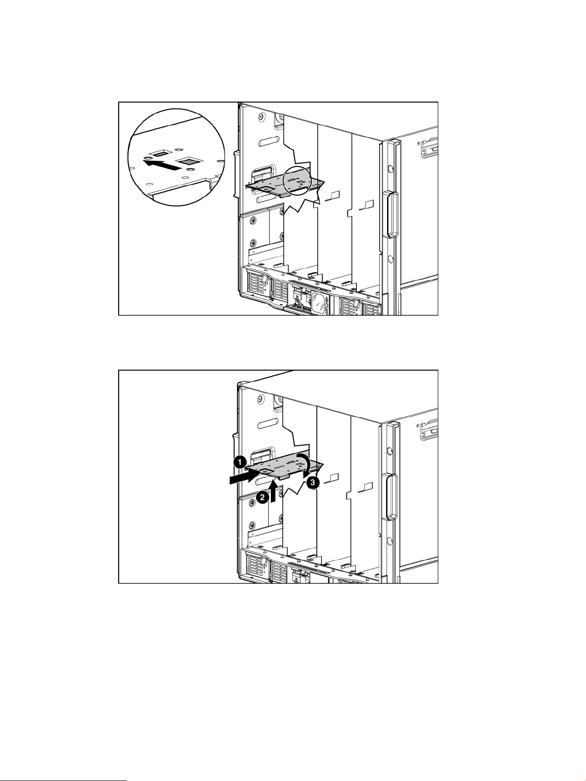
Removing a c7000 device bay divider
1. Slide the device bay shelf locking tab to the left to open it.
2. Push the device bay shelf back until it stops, lift the right side slightly to disengage the two
tabs from the divider wall, and then rotate the right edge downward (clockwise).
Installing and powering on the server blade 15
Page 16
3. Lift the left side of the device bay shelf to disengage the three tabs from the divider wall, and
then remove it from the enclosure.
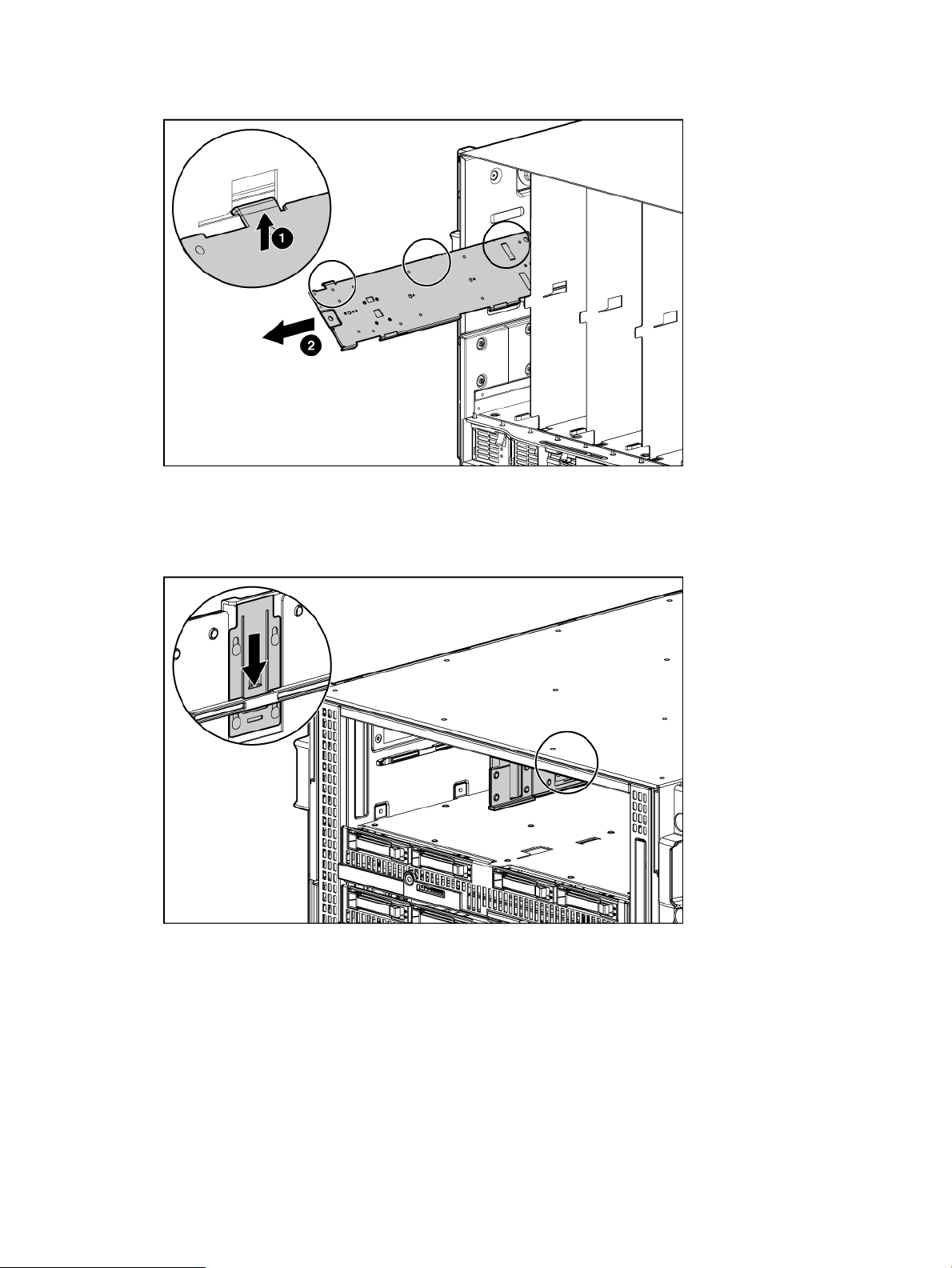
Removing a c3000 device bay mini-divider or device bay divider
1. Slide the locking tab down.
16 Installing the server blade into the enclosure
Page 17
2. Remove the mini-divider or divider:
• c3000 mini-divider:
Push the divider toward the back of the enclosure until the divider drops out of the
enclosure.
• c3000 divider
a. Push the divider toward the back of the enclosure until it stops.
b. Slide the divider to the left to disengage the tabs from the wall.
c. Rotate the divider clockwise.
d. Remove the divider from the enclosure.
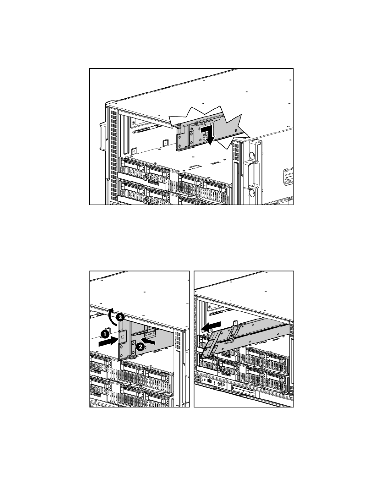
Installing interconnect modules
For specific steps to install interconnect modules, see the documentation that ships with the
interconnect module.
Installing and powering on the server blade 17
Page 18
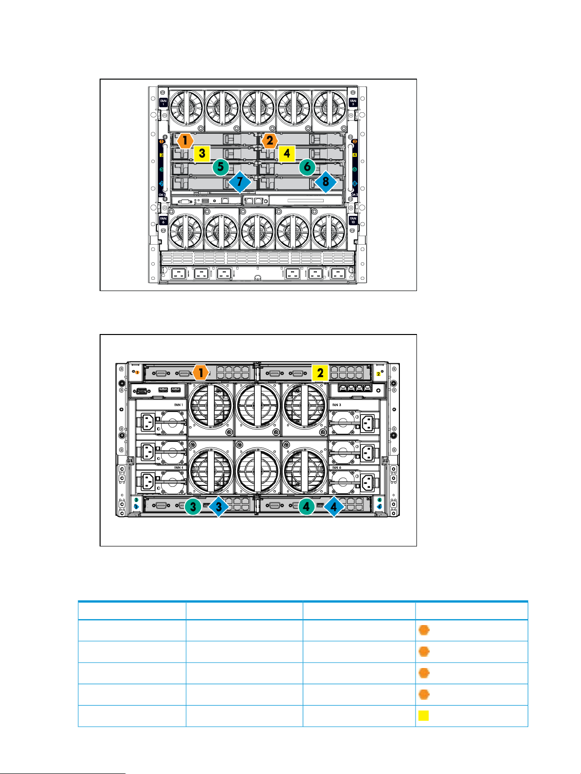
Interconnect bay numbering and device mapping
• HP BladeSystem c7000 Enclosure
• HP BladeSystem c3000 Enclosure
To support network connections for specific signals, install an interconnect module in the bay
corresponding to the embedded NIC or mezzanine signals.
18 Installing the server blade into the enclosure
Interconnect bay labelsc3000 interconnect bayc7000 interconnect bayServer blade signal
11NIC 1 (Embedded)
12NIC 2 (Embedded)
11NIC 3 (Embedded)
12NIC 4 (Embedded)
23 and 4Mezzanine 1
Page 19
For detailed port mapping information, see the HP BladeSystem enclosure installation poster or
the HP BladeSystem enclosure setup and installation guide for your product on the HP website
(http://www.hp.com/go/bladesystem/documentation).
Installing the server blade into the enclosure
NOTE: When installing additional blades into an enclosure, additional power supplies might
also be needed to meet power requirements. For more information, see the HP BladeSystem
enclosure setup and installation guide for your product on the HP website (http://www.hp.com/
go/bladesystem/documentation).
NOTE: Before installing and initializing the server blade, install any server blade options, such
as an additional processor, hard drive, or mezzanine card.
1. Remove the connector covers if they are present.
Interconnect bay labelsc3000 interconnect bayc7000 interconnect bayServer blade signal
3 and 45 and 6Mezzanine 2
3 and 47 and 8
3 and 45 and 6Mezzanine 3
3 and 47 and 8
2. Prepare the server blade for installation.
Installing and powering on the server blade 19
Page 20
3. Install the server blade.
The server blade should come up to standby power. The server blade is at standby power if the
blade power LED is amber.
Server blade power states
The server blade has three power states: standby power, full power, and off. Install the server
blade into the enclosure to achieve the standby power state. Server blades are set to power on to
standby power when installed in a server blade enclosure. Verify the power state by viewing the
LEDs on the front panel, and using Table 5.
Table 5 Power States
Power States
20 Installing the server blade into the enclosure
Server Blade Installed
in Enclosure?
Front Panel Power
Button Activated?
DC Power Applied?Standby Power
Applied?
NoYesNoYesStandby power
YesYesYesYesFull power
NoNoNoNoOff
Page 21

Powering on the server blade
Use one of the following methods to power on the server blade:
NOTE: To power on blades in a conjoined configuration, only power on the Monarch blade.
See “ Blade Link bay location rules” for rules on the definition of the Monarch blade.
• Use a virtual power button selection through iLO 3.
• Press and release the Monarch power button.
When the server blade goes from the standby mode to the full power mode, the blade power LED
changes from amber to green.
For more information about iLO 3, see “Using iLO 3” (page 25).
Powering off the server blade
Before powering down the server blade for any upgrade or maintenance procedures, perform a
backup of critical server data and programs.
Use one of the following methods to power off the server blade:
NOTE: To power off blades in a conjoined configuration, only power off the Monarch blade.
• Use a virtual power button selection through the iLO 3 GUI (Power Management, Power &
Reset) or the iLO 3 TUI commands.
This method initiates a controlled remote shutdown of applications and the OS before the
server blade enter standby mode.
• Press and release the Monarch power button.
This method initiates a controlled shutdown of applications and the OS before the server blade
enter standby mode.
• Press and hold the Monarch power button for more than 4 seconds to force the server blade
to enter standby mode.
This method forces the server blade to enter standby mode without properly exiting applications
and the OS. It provides an emergency shutdown method in the event of a hung application.
Installing the Blade Link for BL860c i4, BL870c i4 or BL890c i4 configurations
IMPORTANT: Without an attached Blade Link, the server blades will not power on.
Installing the Blade Link for BL860c i4, BL870c i4 or BL890c i4 configurations 21
Page 22

NOTE: Before installing the Blade Link for BL870c i4 or BL890c i4, make sure the following
statements are true:
• All blades have the same CPU SKUs
• All blades have the same hardware revision (only use BL860c i4, BL870c i4, or BL890c i4
Server Blades)
• All blades have CPU0 installed
• All blades have the same firmware revision set
• All blades follow the memory loading rules for your configuration, see “DIMMs” (page 44)
• The enclosure OA firmware is compatible with the blade firmware
• The Monarch blade has an ICH mezzanine card installed
• The proper Blade Link is being used for your configuration
To check on the blade hardware revisions and CPU SKUs, go to the Command Menu in the iLO
3 TUI and enter the DF command. This dumps the FRU content of the blades.
NOTE: If you will be upgrading an initial installation, see the user service guide for more
information on server blade upgrades.
Blade Link bay location rules
BL1
Number of
conjoined
bladesClass
for BL860c
i4)
Supported
enclosures
c70001 (standard
c3000
location rules for
blades
Partner blade
support?Blade location rules
YesNo specific bay
Partner blade
half-height bay
number / Server
blade full-height bay
number
Bottom half-height
adjacent bay, paired
with the server blade
in full-height bays
1&2, 3&4, 5&6, or
7&8
Half-height bay 8,
paired with the
server blade in
full-height bay 3.
CAUTION: The bay
mini-divider must be
installed in the
c3000 enclosure to
ensure the partner
blade is inserted
correctly. Failure to
install the bay
mini-divider might
result in damage to
the blade or
enclosure when
installing the partner
1
blade.
c70002 (BL870c i4)BL2
22 Installing the server blade into the enclosure
N/ANoBays 1&2, 3&4,
5&6, or 7&8 with
Monarch blade in
odd bay
Page 23

Number of
conjoined
bladesClass
Supported
enclosures
Partner blade
support?Blade location rules
Partner blade
half-height bay
number / Server
blade full-height bay
number
c3000
c7000 only2 (BL870c i4)BL2E
c3000 only2 (BL870c i4)
c7000 only4 (BL890c i4)BL4
c3000 only4 (BL890c i4)
1
For information on installing the c3000 bay mini-divider, see the HP BladeSystem c3000 Enclosure Setup and Installation
Guide.
Bays 1&2, 3&4
with Monarch blade
in odd bay
YesBays 2&3, 4&5 or
6&7 with Monarch
numbering bay 11 paired with
Monarch blade in
even bay using
full-height
numbering.
5&6&7&8, with
Monarch blade
defaulting to slot 1
or slot 5,
respectively
with Monarch blade
defaulting to slot 1
Bottom half-height
bay 9 paired with
full-height bays 2&3,blade in even bay
bottom half-heightusing full-height
full-height bays 4&5,
bottom half-height
bay 13 paired with
full-height bays 6&7
N/ANoBays 2&3 with
N/ANoBays 1&2&3&4 or
N/ANoBays 1&2&3&4
CAUTION: Using the incorrect Blade Link can cause damage to the Blade Link and to the
connectors on both the Blade Link and the server blades.
IMPORTANT: Failure to follow bay location rules can prevent server blade power on.
NOTE: The manufacturing part numbers for the Blade Link is located on a sticker on the PCA.
“Upgrading a conjoined configuration” (page 54)
To install the Blade Link:
1. Log on to the OA.
2. Install the first blade into the lowest bay number, this blade becomes the Monarch blade
(“Installing the server blade into the enclosure”).
3. Wait 10 seconds. The IP address of the installed blade appears in the OA.
4. Insert each adjacent blade, waiting 10 seconds between blades.
NOTE: The blades will go into stand-by
5. Using the OA, verify that the rest of the blades that will be conjoined have an IP address and
are powered off.
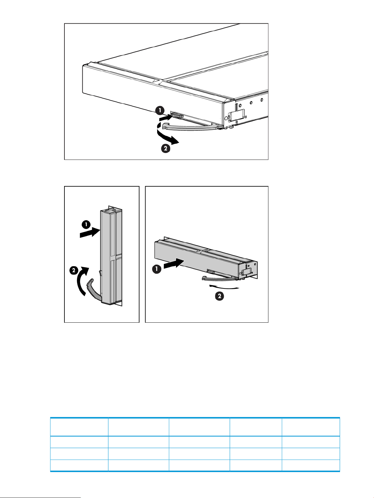
6. Remove the plastic protectors from the connectors on the back of the Blade Link.
7. Push in the blue release latch on the handle to release the handle.
Installing the Blade Link for BL860c i4, BL870c i4 or BL890c i4 configurations 23
Page 24
8. Pull the handle all the way out
9. Align the guide pins on the back of the Blade Link to the holes on the front of the server blades.
As you insert the pins into the holes, ensure the face on the Blade Link is evenly aligned parallel
to the face of the server blades.
10. Press firmly on the left and right sides of the Blade Link face until the handle naturally starts to
close.
CAUTION: If not properly aligned, you can damage the Blade Link
11. Close the handle when it has engaged.
12. Log into iLO 3 on the Monarch blade. For more information, see the HP Integrity iLO3
Operations Guide.
13. In iLO 3, go to the Command Menu and execute xd -r to reboot all of the iLO 3s in the
conjoined set.
14. Run the conjoin checks
Integrity BL870c i4 and BL890c i4 systems go through a process called “conjoining” when
the Blade Link is attached. The system cannot boot until that process is completed properly.
a. Execute the following CM commands in the iLO 3 TUI to show data from all blades. This
information can be used to determine if the blades are successfully conjoined:
i. DF— Lists the FRUs on all of the blades (2 or 4).
ii. SR — Shows a table of each blades firmware revisions.
iii. Blade— Shows information about the OA and the bays used.
b. Check to see if the OA shows a properly conjoined system from its GUI.
IMPORTANT: The secondary UUID and other system variables are stored on the Monarch
blade. If you do not put the Monarch blade in the leftmost slot, your system variables will not
match. If you ever change your iLO 3 configuration (such as adding users) that data is also
stored on the Monarch blade.
NOTE: Auxiliary blades are not slot dependent after being installed and configured, however
when the conjoined systems ship, they come with A, B, C, D stickers located under the Blade
Links. While auxiliary blades are not slot dependent after being installed and configured, HP
recommends using the shipped order to ensure proper auxiliary blade function.
24 Installing the server blade into the enclosure
Page 25

15. Still in the iLO 3 Command Menu, power on the Monarch blade with the PC -on -nc
command. Powering on the Monarch blade will power the entire conjoined system on.
16. Boot the Monarch blade. Booting the Monarch blade boots the entire conjoined system.
Using iLO 3
The iLO 3 subsystem is a standard component of selected server blades that monitors blade health
and provides remote server manageability. The iLO 3 subsystem includes an intelligent
microprocessor, secure memory, and a dedicated network interface. This design makes iLO 3
independent of the host server and operating system. The iLO 3 subsystem provides remote access
to any authorized network client, sends alerts, and provides other server management functions.
Using iLO 3, you can:
• Remotely power on, power off, or reboot the host server.
• Subscribe to we-man alerts from iLO 3 regardless of the state of the host server.
• Access advanced troubleshooting features through the iLO 3 interface.
• Access Remote Console and vMedia functionality.
For more information about iLO 3 basic features, see the iLO 3 documentation on the HP website
(http://h20341.www2.hp.com/integrity/w1/en/software/integrity-lights-out.html?
jumpid=ex_r11294_us/en/large/tsg/go_integrityilo).
Accessing UEFI or the OS from iLO 3 MP
UEFI is an architecture that provides an interface between the server blade OS and the server
blade firmware. UEFI provides a standard environment for booting an OS and running preboot
applications.
Use this procedure to access UEFI or the OS from the iLO 3 MP. Your security parameters were
set regarding remote access.
1. Retrieve the factory iLO 3 password from the iLO 3 Network pull tag located on the right side
of the Monarch blade.
2. From the MP Main Menu, enter the co command to access the Console.
NOTE: Terminal windows should be set to a window size of 80 columns x 25 rows for
optimal viewing of the console at UEFI.
3. After memory test and CPU late self test the following message appears:
Press Ctrl-C now to bypass loading option ROM UEFI drivers.
The prompt will timeout if Ctrl-C is not pressed within a few seconds. If Ctrl-C is pressed, you
will be presented with two options:
• Bypass loading from I/O slots.
• Bypass loading from I/O slots and core I/O.
The Bypass loading from I/O slots and core I/O option may be useful if a bad core I/O
UEFI driver is preventing system boot. USB drives can still be used at the UEFI shell to
update core I/O drivers.
CAUTION: Hitting Ctrl-C before the prompt will not work and may even disable this
feature, be sure wait for the prompt before hitting Ctrl-C.
NOTE: It can take several minutes for this prompt to appear, and the window of time
when Ctrl-C can be pressed is very short. For typical boots, HP recommends that you let
the prompt time out.
After selecting an option, boot will proceed.
Using iLO 3 25
Page 26
NOTE: If no option is selected, normal boot will proceed after ten seconds.
4. Depending on how the server blade was configured from the factory, and if the OS is installed
at the time of purchase, you are taken to:
• UEFI shell prompt
• OS login prompt
If the server blade has a factory-installed OS, you can interrupt the boot process to configure
your specific UEFI parameters.
If you are at the UEFI shell prompt, go to “UEFI Front Page” (page 26).
If you are at the OS login prompt, go to “OS login prompt” (page 28).
UEFI Front Page
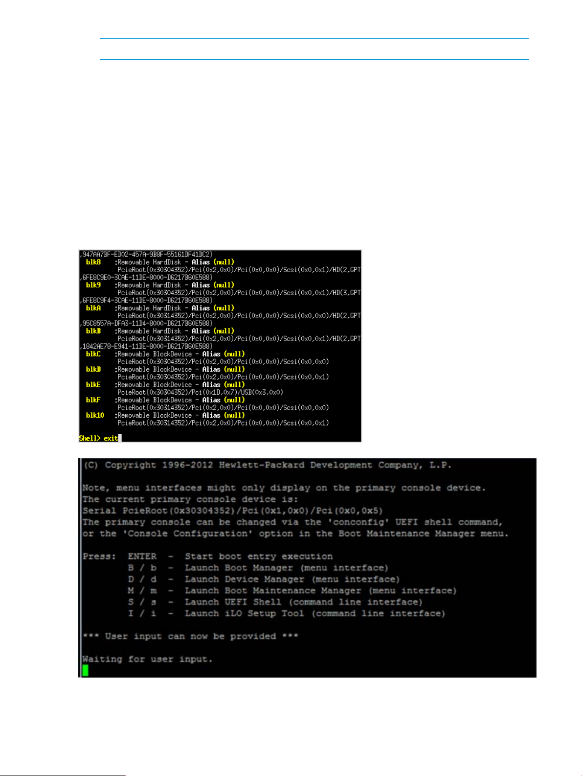
If you are at the UEFI shell prompt, enter exit to get to the UEFI Front Page.
To view boot options, or launch a specific boot option, press B or b to launch the Boot Manager.
26 Installing the server blade into the enclosure
Page 27
To configure specific devices, press D or d to launch the Device Manager. This is an advanced
feature and should only be performed when directed.
To perform maintenance on the system such as adding, deleting, or reordering boot options, press
M or m to launch the Boot Maintenance Manager.
Accessing UEFI or the OS from iLO 3 MP 27
Page 28
To perform more advanced operations, press S or s to launch the UEFI Shell.
To view the iLO 3 LAN configuration, press I or i to launch the iLO 3 Setup Tool.
Saving UEFI configuration settings
There are other UEFI settings you can configure at this time. For more UEFI configuration options,
see Appendix A (page 125).
Booting and installing the operating system
From the UEFI Front Page prompt, you can boot and install in either of two manners:
• If your OS is loaded onto your server blade, see “Operating system is loaded onto the server
blade” (page 28).
• If the OS is not installed onto your server blade, see “Operating system is not loaded onto
the server blade” (page 28).
Operating system is loaded onto the server blade
If the OS is loaded on your server blade, normally UEFI will automatically boot to the OS. If the
UEFI Front Page is loaded, press ENTER to start auto boot, or B or b to select a specific boot option
for your OS.
• Use your standard OS logon procedures, or see your OS documentation to log on to your
OS.
Operating system is not loaded onto the server blade
There are two options on how to load the OS if it is not loaded onto your server blade.
• To load the OS from a DVD, see “Installing the OS from an external USB DVD device or tape
device” (page 30).
• To load the OS using Ignite-UX, see “Installing the OS using HP Ignite-UX” (page 31).
OS login prompt
If your server blade is at the OS login prompt after you establish a connection to the server blade,
use your standard OS log in procedures, or see your OS documentation for the next steps.
28 Installing the server blade into the enclosure
Page 29

Installing the latest firmware using HP Smart Update Manager
The HP Smart Update Manager utility enables you to deploy firmware components from either an
easy-to-use interface or a command line. It has an integrated hardware discovery engine that
discovers the installed hardware and the current versions of firmware in use on target servers. This
prevents extraneous network traffic by only sending the required components to the target. HP
Smart Update Manager also has logic to install updates in the correct order and ensure all
dependencies are met before deployment of a firmware update. It also contains logic to prevent
version-based dependencies from destroying an installation and ensures updates are handled in
a manner that reduces any downtime required for the update process. HP Smart Update Manager
does not require an agent for remote installations.
Key features of HP Smart Update Manager are:
• GUI and CLI–command line interface
• Dependency checking, which ensures appropriate installation order and dependency checking
between components
• Intelligent deployment deploys only required updates
• Support for updating firmware on network-based targets, such as the OA, iLO (through the
Network Management Port), and VC Ethernet modules
• Improved deployment performance
• Remote command-line deployment
• Windows X86 or Linux X86 support
HP Smart Update Manager is included in the firmware bundles download from http://www.hp.com,
and is supported on the BL860c i4, BL870c i4, and BL890c i4.
For more information about HP Smart Update Manager, see the HP Smart Update Manager User
Guide (www.hp.com/support/HP_Smart_Update_Manager_UG_en).
Installing the latest firmware using HP Smart Update Manager 29
Page 30

4 Operating system procedures
Operating systems supported on the server blade
• HP-UX 11i v3 HWE 1209
Installing the operating system onto the server blade
The following procedures describe generalized operating system installation. For more details, see
the operating system documentation.
Installing the OS from an external USB DVD device or tape device
NOTE: Tapeboot requires BL8x0c i4 system firmware bundle 42.06 or later and a partner tape
blade, or an additional 51378-B21 Integrity Smart Array P711m HBA running 6.22 firmware or
later to boot from an Ultrium 6250 tape drive.
1. If using an external USB DVD device:
a. Connect the Integrity SUV cable to the front of the Monarch server blade.
b. Connect the USB DVD cable to one of the USB ports on the SUV cable.
NOTE: Some DVD drives might also require a separate power connection.
c. Turn on the external USB DVD device.
2. Insert the OS media into the USB DVD device or tape device.
3. Power on the server blade and boot to UEFI. If the server blade is already powered on, then
reboot to UEFI using the reset command at the UEFI prompt.
4. From the UEFI Front Page, press S or s to launch the UEFI Shell.
NOTE: If the device is already selected or you already know the device name, then skip the
following step.
If you are using a tape device, when the UEFI shell comes up, you should see a message
similar to the following on the console:
HP Smart Array P212 Controller (version 6.22)
Tape Drive(s) Detected:
Port: 1I, box:0, bay: 3 (SAS)
The message may also be similar to the following.
HP Smart Array P711m Controller (version 6.22) 0 Logical Drives
Tape Drive(s) Detected:
Port: 2E, box:1, bay: 9 (SAS)
NOTE:
If you do not see a line starting with Port and ending with (SAS), the tape is not connected
correctly or it is not responding.
30 Operating system procedures
Page 31

5. Locate the device you want to boot from.
a. For USB DVD, locate the device:
i. Use the map command to list all device names from the UEFI Shell prompt. The map
command displays the following:
fs2:\> map
Device mapping table
fs6 :Removable CDRom - Alias cd66d0a blk6
PcieRoot(0x30304352)/Pci(0x1D,0x7)/USB(0x3,0x0)/CDROM(0x0)
From the list generated by the map command, locate the device name (in this example,
fs6)
NOTE: Your DVD drive might not be named fs6. Make sure you verify the ID
appropriate to your DVD device.
ii. At the UEFI shell prompt, specify the device name for the DVD-ROM and then enter
the UEFI install command, as in the following example:
Shell> fs6:
fs6:\> install
b. For tape, locate the device:
• To boot from tape once you are at the UEFI shell:
Shell> tapeboot select
01
PcieRoot(0x30304352)/Pci(0x8,0x0)/Pci(0x0,0x0)/SAS(0x50060B00007F6FFC,0x0,0x1,NoTopology,0,0,0,0x0)
Select Desired Tape: 01 <<input 01
• If the correct media is installed, it will boot from tape when you enter the index
number.
• If there is no media in the SAS tape drive and you select 1, the following message
appears:
tapeboot: Could not load tapeboot image
6. The OS now starts loading onto the server blade. Follow the on-screen instructions to install
the OS fully.
7. Continue with “Configuring system boot options” (page 32)
Installing the OS using HP Ignite-UX
Ignite-UX is an HP-UX administration toolset that enables:
• Simultaneous installation of HP-UX on multiple clients
• The creation and use of custom installations
• The creation of recovery media
• The remote recovery of clients
To install the OS onto the server blade using Ignite-UX, go to www.hp.com/go/ignite-ux.
Installing the OS using vMedia
NOTE: Installing the OS using vMedia might be significantly slower than installing using other
methods.
vMedia enables connections of a DVD physical device or image file from the local client system
to the remote server. The virtual device or image file can be used to boot the server with an operating
system that supports USB devices.
vMedia depends on a reliable network with good bandwidth. This is especially important when
you are performing tasks such as large file transfers or OS installations.
Installing the operating system onto the server blade 31
Page 32

For more information regarding loading the OS with vMedia, see the vMedia Chapter of the HP
Integrity Integrated Lights-Out Management Processor Operations Guide.
NOTE: After the OS is loaded, make sure to save your nonvolatile memory settings to preserve
boot entries in case of blade failure.
Configuring system boot options
• Boot Manager
Contains the list of boot options available. Ordinarily the boot options list includes the UEFI
Internal Shell and one or more operating system loaders.
To manage the boot options list for each server, use the UEFI Shell, the Boot Maintenance
Manager, or operating system utilities.
• Autoboot setting
The autoboot setting determines whether a server automatically loads the first item in the
boot options list or remains at the UEFI Front Page menu. With autoboot enabled, UEFI loads
the first item in the boot options list after a designated timeout period.
Configure the autoboot setting for an HP Integrity server using either the autoboot UEFI Shell
command or the Set Time Out Value menu item from the Boot Maintenance Manager.
Examples of autoboot commands for HP-UX:
◦ Disable autoboot from the UEFI Shell by issuing autoboot off
◦ Enable autoboot with the default timeout value by issuing autoboot on
◦ Enable autoboot with a timeout of 60 seconds by issuing the autoboot 60
◦ Set autoboot from HP-UX using setboot
◦ Enable autoboot from HP-UX using setboot -b on
◦ Disable autoboot from HP-UX using setboot -b off
For more information on the autoboot command, enter help autoboot.
Booting and shutting down HP-UX
To boot HP-UX, use one of the following procedures:
• To boot HP-UX normally, see “HP-UX standard boot” (page 33). HP-UX boots in multi-user
mode.
• To boot HP-UX in single-user mode, see “Booting HP-UX in single-user mode” (page 34).
• To boot HP-UX in LVM-maintenance mode, see“Booting HP-UX in LVM-maintenance mode”
(page 34).
Adding HP-UX to the boot options list
You can add the \EFI\HPUX\HPUX.EFI loader to the boot options list from the UEFI Shell or the
Boot Maintenance Manager.
NOTE: On HP Integrity server blades, the operating system installer automatically adds an entry
to the boot options list.
NOTE: To add an HP-UX boot option when logged in to HP-UX, use the setboot command.
For more information, see the setboot(1M) manpage.
To add HP-UX to the list:
32 Operating system procedures
Page 33

1. Access the UEFI Shell environment.
a. Log in to iLO 3 for Integrity and enter the CO command to access the system console.
When accessing the console, confirm that you are at the UEFI Front Page.
If you are at another UEFI menu, then choose the Exit option or press X or x to exit the
menu. Exit until you return to the screen that lists the keys that can be pressed to launch
various Managers.
b. Press S or s to launch the UEFI shell.
2. Access the UEFI System Partition (fsX: where X is the file system number) for the device
from which you want to boot HP-UX.
For example, enter fs2: to access the UEFI System Partition for the bootable file system
number 2. The UEFI Shell prompt changes to reflect the file system currently accessed.
The full path for the HP-UX loader is \EFI\HPUX\HPUX.EFI and it should be on the device
you are accessing.
3. At the UEFI Shell environment, use the bcfg command to manage the boot options list.
The bcfg command includes the following options for managing the boot options list:
• bcfg boot dump – Display all items in the boot options list for the server.
• bcfg boot rm # – Remove the item number specified by # from the boot options list.
• bcfg boot mv #a #b – Move the item number specified by #a to the position specified
by #b in the boot options list.
• bcfg boot add # file.efi "Description" – Add a new boot option to the
position in the boot options list specified by #. The new boot option references file.efi
and is listed with the title specified by Description.
For example, bcfg boot add 1 \EFI\HPUX\HPUX.EFI "HP-UX 11i v3" adds
an HP-UX 11i v3 item as the first.
For more information, see the help bcfg command.
4. Exit the console and iLO 3 MP interfaces.
Press Ctrl–B to exit the system console and return to the iLO 3 MP Main Menu. To exit the MP,
press X or x at the Main Menu.
HP-UX standard boot
Use either of the following procedures to boot HP-UX:
• “Booting HP-UX from the UEFI Boot Manager” (page 33)
• “Booting HP-UX from the UEFI Shell” (page 34)
Booting HP-UX from the UEFI Boot Manager
1. From the UEFI Boot Manager menu, choose an item from the boot options list to boot HP-UX.
2. Access the UEFI Boot Manager menu for the server on which you want to boot HP-UX.
3. Log in to iLO 3 MP and enter the CO command to choose the system console.
4. Confirm you are at the UEFI Front Page. If you are at another UEFI menu, then choose the Exit
option or press X or x to exit the menu. Exit until you return to the screen that lists the keys
that can be pressed to launch various Managers. Press B or b to launch the Boot Manager.
5. At the UEFI Boot Manager menu, choose an item from the boot options list.
Each item in the boot options list references a specific boot device and provides a specific set
of boot options or arguments you use when booting the device.
6. Press Enter to initiate booting using your chosen boot option.
Booting and shutting down HP-UX 33
Page 34

7. Exit the console and iLO 3 MP interfaces.
8. Press Ctrl–B to exit the system console and return to the MP Main Menu. To exit the MP Main
Menu, press X or x.
Booting HP-UX from the UEFI Shell
1. Access the UEFI Shell.
2. From the UEFI Front Page, press S or s to launch the UEFI shell.
3. Use the map command to list the file systems (fs0, fs1, and so on) that are known and have
been mapped.
4. To select a file system to use, enter its mapped name followed by a colon (:). For example, to
operate with the boot device that is mapped as fs0, enter fs0: at the UEFI Shell prompt.
5. Enter HPUX at the UEFI Shell command prompt to launch the HPUX.EFI loader from the
currently selected boot device.
If needed, specify the full path of loader by entering \EFI\HPUX\HPUX at the UEFI Shell
command prompt.
6. Allow the HPUX.EFI loader to proceed with the boot command specified in the AUTO file,or
manually specify the boot command.
By default, the HPUX.EFI loader boots using the loader commands found in the
\EFI\HPUX\AUTO file on the UEFI System Partition of the selected boot device. The AUTO
file typically contains the boot vmunix command.
To interact with the HPUX.EFI loader, interrupt the boot process (for example, type a space)
within the time-out period provided by the loader. To exit the loader, use the exit command,
which returns you to UEFI.
Booting HP-UX in single-user mode
1. Use steps 1–5 from “Booting HP-UX from the UEFI Shell” (page 34) to access the UEFI shell
and launch the HPUX.EFI loader.
2. Access the HP-UX Boot Loader prompt (HPUX>) by pressing any key within the 10 seconds
given for interrupting the HP-UX boot process. Use the HPUX.EFI loader to boot HP-UX in
single-user mode in step 3
After you press a key, the HPUX.EFI interface (the HP-UX Boot Loader prompt, HPUX>)
launches. For help using the HPUX.EFI loader, enter the help command. To return to the UEFI
Shell, enter exit.
3. At the HPUX.EFI interface (the HP-UX Boot loader prompt, HPUX>) enter the boot -is
vmunix command to boot HP-UX (the /stand/vmunix kernel) in single-user (-is) mode.
Booting HP-UX in LVM-maintenance mode
The procedure for booting HP-UX into LVM Maintenance Mode is the same as for booting into
single user mode (“Booting HP-UX in single-user mode” (page 34)), except use the -lm boot option
instead of the -is boot option:
HPUX> boot -lm vmunix
Shutting down HP-UX
For more information, see the shutdown( 1M) manpage.
1. Log in to HP-UX running on the server that you want to shut down or log in to iLO 3 MP for
the server and use the Console menu to access the system console. Accessing the console
through iLO 3 MP enables you to maintain console access to the server after HP-UX has shut
down.
34 Operating system procedures
Page 35

2. Issue the shutdown command with the appropriate command-line options.
The command-line options you specify determines the way in which HP-UX shuts down and
whether the server is rebooted.
Use the following list to choose an HP-UX shutdown option for your server:
• Shut down HP-UX and halt (power off) the server using the shutdown -h command.
Reboot a halted server by powering on the server using the PC command at the iLO 3
MP Command menu.
• Shut down HP-UX and reboot the server by issuing the shutdown -r command.
Booting and shutting down HP-UX 35
Page 36

5 Optional components
If your server blade has no additional components to install, go to “Installing and powering on the
server blade” (page 14).
Partner blades
The following partner blades are supported:
• Ultrium 448c Tape Blade
• SB920c Tape Blade
• SB1760c Tape Blade
• SB3000c Tape Blade
• SB40c Storage Blade
• D2200sb Storage Blade
IMPORTANT: In c7000 enclosures, partner blades are supported with BL860c i2 servers and
BL870c i2 servers with BL2E blade links.
In c3000 enclosures, partner blades are supported with BL860c i2 servers.
Partner blades are not supported with BL890c i2 servers.
Partner blade slotting rules are dependent on the conjoined blade configuration. For more
information on partner bay blade locations, see “Installing the Blade Link for BL860c i4, BL870c
i4 or BL890c i4 configurations” (page 21).
NOTE: SAS tape boot is now supported with tape blades on HP Integrity BL860c i4, BL870 i4,
and BL980 i4 server blades.
NOTE: PCIe Gen-1 (driven from the ICH10 on the monarch blade’s ICH mezzanine card) provides
the interface to the partner blades. A separate mezzanine pass-thru card is not required.
36 Optional components
Page 37

Hot-plug SAS disk drives
The server blade supports up to two hot-plug SAS drives.
CAUTION: To prevent improper cooling and thermal damage, do not operate the server blade
or the enclosure unless all hard drive and device bays are populated with either a component or
a blank.
IMPORTANT: The disk drive does not seat properly when 180° out of alignment. Verify the
orientation before insertion.
NOTE: For a list of supported disk drives for the server blade, see: “Server blade components
list” (page 99).
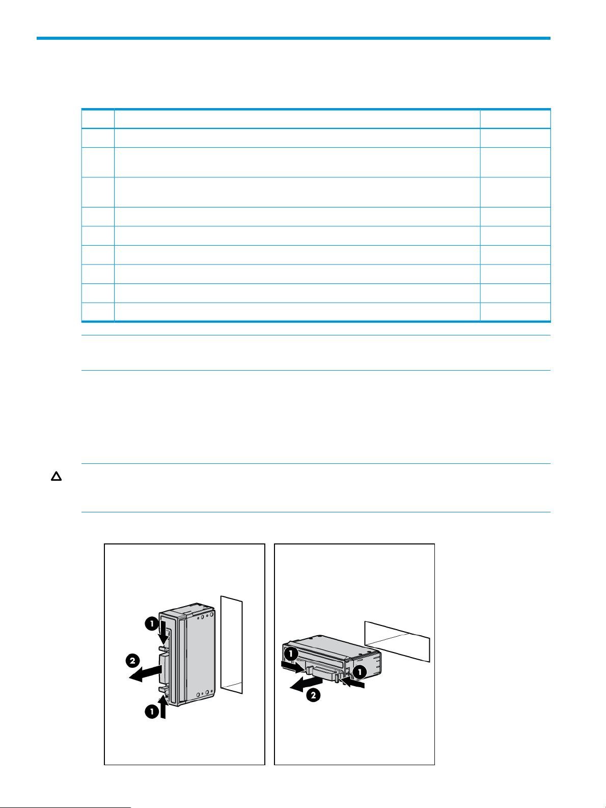
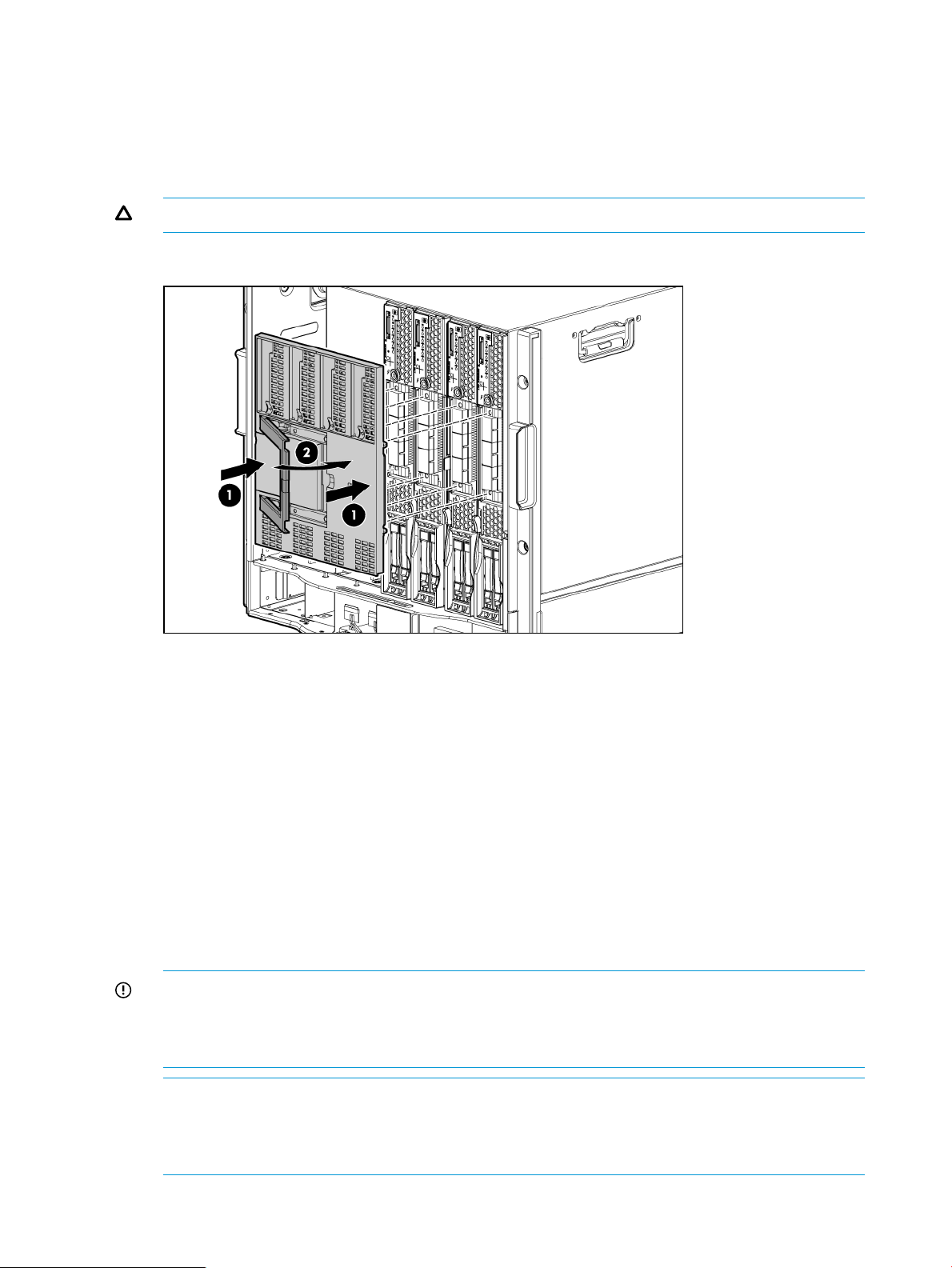
1. Remove the hard drive blank.
2. Prepare the hard drive.
3. Slide the drive into the cage until it is fully seated.
Hot-plug SAS disk drives 37
Page 38

4. Close the lever to lock the drive into place.
Installing internal components
Removing the access panel
1. Lift the access panel latch.
2. Slide the access panel backwards approximately 2 cm (0.75 in).
3. Remove the access panel by lifting it straight up and off the server blade.
After the access panel is off, you can do the following:
• Add an additional processor (“Processor and heatsink module”).
• Add additional memory DIMMs (“DIMMs”).
• Add additional mezzanine cards (“Mezzanine cards”).
38 Optional components
Page 39

Processor and heatsink module
Processor load order
Observe the following guidelines when installing additional processors:
• In a BL860c i4, CPU0 is installed before CPU1.
• In a BL870c i4 or BL890c i4, each blade must have CPU0 installed.
• When adding additional CPUs in a conjoined configuration:
Load both CPU0 and CPU1 in the Monarch blade first◦
◦ Load additional CPUs in sequence, from lowest slot-numbered blade to highest.
CAUTION: The pins on the processor socket are very fragile. Any damage to them might require
replacing the server blade base unit.
CAUTION: To avoid damage to the processor, verify that the plastic tabs on the processor are
pulled fully out before installation.
CAUTION: To avoid damage to the processor, handle the processor only by the edges. Do not
touch the bottom of the processor, especially the contact area.
CAUTION: To prevent possible server blade malfunction and damage to the equipment,
multiprocessor configurations must contain processors with the same part number.
The processor and heatsink ship as two separate units and are coupled together during installation
into the server blade.
1. Remove the CPU airflow baffle.
Installing internal components 39
Page 40

2. Transfer the duplicate part/serial numbers label from the processor module to the processor
heatsink.
a. Remove the duplicate tear-away label that lists the part and serial numbers from the
processor module.
b. Place the label on the top of the heatsink.
3. Install the processor over the load posts.
NOTE: Ensure pin 1, indicated on the empty socket with an embossed triangle, matches the
pin 1 marker on the processor module, the chamfered corner of its attached voltage regulator
heatsink.
4. Remove the heatsink cover.
40 Optional components
Page 41

CAUTION: During installation, after removing the protective cover from the heatsink:
• Do not touch or come into contact with the thermal interface material.
• Immediately install the heatsink.
CAUTION: To avoid damage to the server blade and processor, ensure the processor heatsink
locking handle is fully back against the stops, rotated about 120° back. Also verify that the
plastic tabs on the processor heatsink are pulled fully out before installation.
5. Install the heatsink over the load posts.
CAUTION: Do not lower the heatsink locking handle before pushing the plastic locking tabs
into place.
Installing internal components 41
Page 42

CAUTION: To prevent thermal instability and damage to the server blade, do not separate
the processor module from the processor's heatsink after they have been coupled.
42 Optional components
Page 43

6. Secure the heatsink to the processor
a. Slide both plastic locking tabs into place. (See callout 1 in the following figure).
b. Grasp and rotate the latch downward. (See callout 2 in the following figure.)
WARNING! The heatsink locking lever can constitute a pinch hazard, keep your hands
on top of the lever during installation to avoid personal injury.
NOTE: Positive engagement clicking should occur during mating of the processor heat
sink and processor module onto the socket to ensure proper seating.
7. Connect the power cord. (See callout 3 in the previous figure).
8. Tie wrap the processor cable to the right tie point on the processor assembly.
CAUTION: When the CPU is installed, dress all slack in the power cable to the connector
end of the cable. Failure to do so could result in pinched or damaged CPU power cables.
Installing internal components 43
Page 44

DIMMs
IMPORTANT: If you are adding an additional processor to your server blade, the DIMMs in the
server blade must be reconfigured to support both CPUs. For more information, see “DIMM pair
load order” (page 45).
DIMM installation guidelines
Observe the following guidelines when installing memory:
• Use only HP low-profile (1.2 in.) DIMMs.
IMPORTANT: DIMMs from other sources may adversely affect data integrity.
• In a BL860c i4 Server Blade, memory is loaded in identical pairs.
• In a BL870c i4 or BL890c i4 Server Blade, memory is loaded in quads that are systematically
loaded between blades and processors.
◦ The BL870c i4 has a single interleaving domain that allows mixing two DIMM types
within the domain. The highest DIMMs get loaded first in quads, alternating between
blades and processor sockets; then the lower DIMMs get loaded in quads, alternating
between blades and processor sockets .
◦ The BL890c i4 system has dual interleaving domains, with each interleave domain
consisting of two adjacent blades. In this system different DIMM types cannot be mixed
in the same interleaving domain. Higher capacity DIMMs are loaded in quads alternating
between blades 1 and 2 and their processor sockets; then the lower capacity DIMMs are
loaded in quads alternating between blades 3 and 4 and their processor sockets. This
means there can never be more than 12 quads of either of the two DIMM types.
IMPORTANT: If loading a single DIMM type in an 8 socket system, the DIMMs have to
be loaded alternating between blades and processor sockets since starting to load one
interleaving domain first, then the second can result in an unbalanced memory
configuration.
• Different densities in different pairs or quads are supported, provided the following rules are
kept.
Only two DIMM sizes can be mixed in a BL870c i4 or BL890c i4 Server Blade. Mixing more
than two DIMM pair capacities is only supported on the BL860c i4.
◦ In a BL870c i4 Server Blade, the two DIMM sizes must alternate between blades. Load
all of one DIMM size, then repeat with the second DIMM size.
◦ In a BL890c i4 Server Blade, blades 1 and 2 must have one DIMM size and blades 3
and 4 must have the other DIMM size. If only one DIMM size is used on BL980c i4,
alternate between all 4 blades.
IMPORTANT: If loading a single DIMM type in a BL980c i4, the DIMMs have to be
loaded alternating between blades and processor sockets, since starting to load one
interleaving domain first, then the second, can result in an unbalanced memory
configuration.
NOTE: HP Integrity Server Blade upgrades follow the same DIMM loading rules.
See“Upgrading a conjoined configuration” (page 54) for more information on server
blade upgrades.
44 Optional components
Page 45

Performance
The maximum number of usable DIMM slots, and therefore the maximum amount of memory for
any particular configuration is tied to the number of processors used in the configuration. In addition,
the conjoined blade products all have minimum processor recommendations (oner per conjoined
blade) for best performance.
There are 12 DIMMs associated with each processor. Each processor has DIMM pairs A through
F. A processor must installed to access its associated memory. A processor can be installed without
memory as long as one of the processors in the conjoined system has memory.
For best performance, the minimum recommendation is a quad of DIMMs for each processor
installed in a conjoined blade product. For best performance (not required), load only the same
type (size) of DIMMs throughout the system. Uniform memory (selected in the memconfig
interleaving options) is supported with a total memory capacity equal to a "power of two" (loading
4, 8, 16, 32, or 64 DIMMs at a time). Therefore, for best performance, if using the uniform memory
selections, load a quad (even better two quads) of DIMMs for each processor. To obtain the fastest
memory access, load a total memory capacity equal to a power of four (4, 16, 64).
IMPORTANT: The system will boot with memory loaded on only one processor. However, from
a performance perspective, this is not a recommended configuration.
To enable Double DRAM chip sparing, for all the DIMMs loaded in the system, use only 4GB,
8GB, or 16GB DIMMs.
The 10GigE LOMs that have jumbo frames enabled require 1GB of main memory for each port
(8GB/server blade). Anything below this minimum results in insufficient memory and a hang either
during the HP-UX boot or during the I/O configuration for the Integrity BL8x0c i4 systems. For
example, the minimum memory configuration for the Integrity BL860c i4 is 8GB, for the BL870c
i4 is 16GB, and for the BL890c i4 is 32GB.
Minimum memory requirements assume the Flex-10/FlexFabric adapters are not installed. Increase
the minimum required memory by 2GB for each Flex-10/FlexFabric mezzanine card that is installed
into the system.
DIMM pair load order
Figure 1 DIMM quad load order
Installing internal components 45
Page 46

Figure 2 Mixed DIMM load order
Table 6 DIMM pair load order
CPU1CPU0
——4A3A1st
CPU0 only
Both CPUs loaded
——10B9B2nd
——6C1C3rd
——12D7D4th
——5E2E5th
——11F8F6th
——4A3A1st
7A1A——2nd
——10B9B3rd
10B6B——4th
——6C1C5th
9C3C——6th
——12D7D7th
12D4D——8th
——5E2E9th
8E2E——10th
——11F8F11th
46 Optional components
11F5F——12th
Page 47

DIMM quad load order rules
Figure 3 DIMM quad load order
Figure 4 Mixed DIMM load order
Table 7 DIMM quad load order
Both CPUs
loaded
CPU1CPU0
————10B9B4A3A1st
10B6B7A1A————2nd
————12D7D6C1C3rd
12D4D9C3C————4th
————11F8F5E2E5th
11F5F8E2E————6th
Installing internal components 47
Page 48

NOTE:
• If more than two DIMM types are installed in the BL870c i4 or BL890c i4 systems, the customer
will receive a warning indicating that optimum interleaving is not possible and memory may
be de-allocated. Mixing more than two DIMM types is only supported on the BL860c i4.
• If DIMMs are loaded in pairs in the BL870c i4 or BL890c i4 systems, the customer will receive
a warning indicating that the memory is not configured according to the HP loading rules and
some memory may be de-allocated.
Once the memory loading rules have been satisfied, all memory installed in the system will be
recognized.
Installing DIMMS
1. Power off the server blade.
2. For the conjoined products only, remove the Blade Link.
3. Remove the server blade from the enclosure.
4. Remove the access panel.
5. Remove the DIMM baffle (“DIMM baffle” (page 108)).
6. Locate the DIMM slots on the server blade system board.
NOTE: The server blade ships with at least two DIMMs installed in slots 3A and 4A.
7. Ensure the DIMM slot latches are open.
48 Optional components
Page 49

8. Align the DIMM's notch with the slot's notch.
CAUTION: Use only HP low profile DIMMs. DIMMs from other sources might adversely
affect data integrity.
DIMMs do not seat fully if turned the wrong way.
DIMMs in a pair or quad must be identical.
9. Insert a DIMM in a slot and push down firmly until the latches click shut, first one latch and
then the other.
IMPORTANT: To ensure proper function of the memory baffle, all DIMM latched must be in
the CLOSED position.
Mezzanine cards
Optional mezzanine cards enable additional network connectivity and provide Fibre Channel
support. For mezzanine card locations, see “Server blade components” (page 8).
Optional mezzanine cards are classified as Type I mezzanine cards and Type II mezzanine cards.
The card type determines where it can be installed in the server blade:
• Install Type I mezzanine cards on any mezzanine connector.
• Install Type II mezzanine cards only on Mezzanine 2 connector or Mezzanine 3 connector.
To install a card:
1. Power off the server blade and remove it from the server blade enclosure (“Preparing the
server blade for servicing”).
2. Remove the access panel (“Removing the access panel” (page 38)).
3. Remove the mezzanine connector cover.
Installing internal components 49
Page 50

4. Align the mezzanine connector on the option card with the mezzanine connector on the system
board.
5. Press down on the connector to seat the card.
CAUTION: To prevent damage to the server blade, apply pressure over the mezzanine
connector when installing the mezzanine card. Do not apply pressure to the edges of the card.
HP Smart Array P711m Controller
The HP Smart Array P711m is a PCIe card supporting direct attach and shared SAS Storage. This
card is supported in slots 1, 2, and 3 on the Integrity BL860c i4, BL870c i4, and BL890c i4 server
blades.
NOTE: When a mixed configuration of BL860c i4, BL870c i4, and BL890c i4 server blades and
other c-Class server blades is in the same enclosure, the preferred location for the P711m cards
is slot 3.
50 Optional components
Page 51

Supercap pack mounting kit
The HP Smart Array P711m Controller includes a cabled Supercap Pack which mounts inside the
server using the orderable AM341A Mounting Kit for Low profile battery (HP part number
AD399-2132A KIT, RAID BATTERY HOLDER). This kit contains a black metal mounting bracket
and a mezzanine card blank. The mounting bracket clips onto a mezzanine card in slot 1. If no
card is used in slot 1, the mezzanine card blank included in the kit must be installed to mount the
bracket.
For installing the bracket on to the server blade, the mounting bracket has:
• A mezzanine post loop that slides over the abutting mezzanine 2 post
• A thumbscrew clip that clips over the mezzanine 1 card or mezzanine blank thumbscrew
located at the rear of the blade
• • A mezzanine foot that clips over the edge of the mezzanine 1 card or mezzanine card
blank that is installed closest to the center of the blade
For installing the Supercap Pack onto the bracket, the mounting bracket has:
• A C-hook to restrain the cable
• Two restraining clips to restrain the Supercap Pack
Mezzanine foot C-hookCable restraining clips
2
Mezzanine post loop
Installing the Supercap mounting bracket
1. Power off the server blade and remove it from the server blade enclosure (“Preparing the
server blade for servicing”).
2. Remove the access panel (“Access panel” (page 106)).
3. Remove the DIMM baffle (“DIMM baffle” (page 108))
4. Temporarily remove any mezzanine card installed in slot 2 (“Mezzanine cards” (page 115)).
NOTE: Mezzanine slot 1 must contain the P711m Controller, another mezzanine card, or
the mezzanine card blank. If you are installing the P711m card in mezzanine slot 1, do so
now following the instructions “Installing the P711m Controller Board.” If you are not installing
the P711m card in mezzanine slot 1, and no other mezzanine card is present in slot 1, then
install the mezzanine card blank at this time.
5. Clip the mounting bracket onto the mezzanine card or mezzanine card blank.
431
Installing internal components 51
Page 52

6. Press the bracket thumbscrew clip over the thumbscrew closest to the mezzanine post.
7. Push the remaining bracket foot over the other edge of the mezzanine card or mezzanine
card blank.
CAUTION: Push only enough to anchor the bracket, keeping the bracket level.
CAUTION: To avoid damage to the power cable ensure the battery bracket does not pinch
the power cable to the power connectors.
8. Replace any mezzanine cards that you had to remove from mezzanine slot 2 (“Mezzanine
cards” (page 115)).
To remove the component, reverse the procedure.
Installing the P711m controller board
This card is supported in slots 1, 2, and 3 on the Integrity BL860c i4, BL870c i4, and BL890c i4
server blades.
52 Optional components
321
Slot 3Slot 2Slot 1
Page 53

NOTE: When a mixed configuration of BL860c i4, BL870c i4, and BL890c i4 server blades and
other c-Class server blades are in the same enclosure, the preferred location for the P711m cards
is slot 3.
Use the procedure for installing standard mezzanine cards to install the SAS controller board, see
“Mezzanine cards” (page 49) for more information.
Installing the Supercap Pack
The Supercap Pack snaps onto the mounting bracket to secure the Supercap Pack inside the server
blade.
NOTE: The mounting bracket is installed either on top of a mezzanine card in slot 1, or the
mezzanine blank in slot 1, depending upon the customer's configuration. If no card is used in slot
1, the mezzanine card blank must be installed for the bracket to clip onto.
NOTE: The Supercap Pack includes two plastic tabs that must be removed for proper fit in the
BL860c i4, BL870c i4, and BL890c i4 server blades. One tab is located on the rounded end of
the Supercap Pack, the other tab is directly above the cable as it exits the plastic housing of the
Supercap Pack. To remove these tabs, squeeze them firmly toward each other (significant force is
required). Optionally, these two tabs can be clipped off even with the rest of the Supercap Pack.
1. Position the Supercap Pack with the print side down and push the end of the cable that is
connected to the Supercap Pack under the mounting bracket’s C-hook, routing the cable so
its supercap end is on the side of the hook that is away from slot 3
2. Push the other end of the Supercap Pack down between the two restraining clips.
3. Consolidate and secure remaining cable length using tie wrap or similar retention method.
Installing internal components 53
Page 54

To remove the component, reverse the procedure.
Replacing the access panel
1. Place the access panel onto the server blade by lining up the keyways on the panel to the
posts on the server blade chassis.
2. Slide the access panel toward the front of the server blade until the panel lock button snaps
into place.
Upgrading a conjoined configuration
This section contains information required to complete an upgrade of a BL860c i4, BL870c i4, or
BL890c i4 server blade. This document expands on the information provided in the Read This First
document which is included in the upgrade kit.
Procedure summary
1. Original blade server check
The existing blade servers that will be upgraded are checked and prepared for the upgrade
2. Adding resources
The blades for the upgrade are placed together, internal component changes are made if
necessary, blade firmware is updated if necessary, the Upgrade Blade Link is installed, System
Information Parameters are exchanged between the server blades and the new Blade Link,
and then the final system partitioning can be set.
3. Final check
The upgraded sever partitions are booted to the UEFI shell and variables restored if necessary,
the upgraded server is checked for normal operation at a low level, and finally the Operating
System is booted and the system checked for normal operation.
4. Warranty registration
Warranty and support are arranged to be transferred from the server being upgraded to the
upgraded server.
54 Optional components
Page 55

Upgrade kit contents
• The HP Integrity BL860c i4, BL870c i4 & BL890c i4 Server Blade Upgrades Read Me First .
• One of the following Upgrade Blade Links:
AM395A HP BL8x0c i4 Upgrade BL2 Blade Link◦
◦ AM396A HP Integrity BL870c i4 Upgrade BL2-c7E Blade Link
◦ AM398A HP BL8x0c i4 Upgrade BL4 Blade Link
NOTE: Each Blade Link will include a new Product Number label to attach to the system
label carrier card; the actual part number will depend on the type of upgrade ordered.
• AM394A HP Integrity BL8x0c i4 Upgrade Blade. One or more Upgrade Blades may be
included depending on the type of upgrade ordered. These should be pre-installed with ordered
processors, memory, and other components.
Before getting started
IMPORTANT:
• Do not install or use the upgrade Blade Link until explicitly called for in the upgrade procedure.
For more information, see “Blade link and system information parameters” (page 70).
• The server blade firmware may need to be updated on the existing server blades as part of
the upgrade process, see “Determining your current firmware revisions” (page 56) for more
information.
• Processor and memory DIMM loading and distribution follows applicable rules across the
blades. For more information, see “Installing internal components” (page 38), and “Rules for
server blade internal components” (page 60).
• Adding new Upgrade Blades to an enclosure may require additional power supplies in the
enclosure to meet the new power requirements. This situation would be reported by the
enclosure Onboard Administrator. For more information, see the HP BladeSystem setup and
information guide for your enclosure at http://www.hp.com/go/bladesystem/documentation.
• If more than one existing blade server will be combined in the upgrade, one of them must be
designated as the “Monarch Server”. This is the original server which is officially being
upgraded, The Monarch blade from this server will become the Monarch blade in the upgraded
server. Also, the Monarch Server UUID and Serial Number will be transferred to the upgraded
server.
• The OS boot disk must be attached to the designated Monarch Server.
• When VC is used, some rearrangement of the VC server profile may be necessary. See
“Possible changes due to VC profile mapping on the upgraded blade server” (page 72).
• Because the socket count of the upgraded server is likely to be greater than that of the server
being upgraded, a new OS license will probably be required.
• At the end of the upgrade, the Blade Links removed from the original blade servers cannot be
reused.
Installing internal components 55
Page 56

Supported operating systems
• HP-UX 11i v3 OE Update for September 2012
IMPORTANT: If you will be using HP-UX, review the HP-UX errata documentation that is listed at
the following url:
http://www.hp.com/go/Blades-docs
Minimum firmware versions
A minimum set of firmware is required for the blades and blade enclosures involved in the upgrade.
Firmware on the server blades, the enclosure HP Onboard Administrator, and the HP Virtual
Connect Manager (if Virtual Connect interconnect modules are installed) must be updated to at
least the minimum firmware level. Every blade in the upgrade must be at the same firmware level.
IMPORTANT: Any required updates must be checked for and completed during the upgrade
process.
Minimum Firmware LocationMinimum Firmware VersionProduct Name(s)
Go to hp.com —> Support & Drivers
—> enter product name —> select
operating system —> “Cross operating
system”
Go to hp.com —> Support & Drivers
—> enter product name
Go to hp.com —> Support & Drivers
—> enter Interconnect Module product
name
HP Integrity BL870c i4 Server Blade
HP Integrity BL890c i4 Server Blade
Administrator
HP BladeSystem c-Class Virtual
Connect
T42.02HP Integrity BL860c i4 Server Blade
3.55HP BladeSystem Onboard
3.70
IMPORTANT: VCSU version 1.7.0
must be used to update to VC 3.70.
Determining your current firmware revisions
Server blade
IMPORTANT: It is possible to access the iLO TUI before iLO has completed its initialization at
power up. The indicator to know that iLO has completed initialization is the ability to access the
nPartitions command via the TUI.
1. Log into the system iLO 3 MP.
2. From the Main Menu, enter the cm command to access the Command Menu
3. Enter the sr command to view the system FW revisions.
Hewlett-Packard Integrated Lights-Out 3 for Integrity
(C) Copyright 1999-2010 Hewlett-Packard Development Company, L.P.
MP Host Name: ilo002264fee2de
iLO MP Firmware Revision 01.41.01
*************************************************************************
MP ACCESS IS NOT SECURE
A default MP user Administrator/Admin is currently configured
and remote access is enabled. Modify the default password or
delete the default user (see UC command)
OR
Disable all types of remote access (see SA command)
*************************************************************************
MP MAIN MENU:
56 Optional components
Page 57

CO: Console
VFP: Virtual Front Panel
CM: Command Menu
CL: Console Log
SL: Show Event Logs
HE: Main Help Menu
X: Exit Connection
[ilo002264fee2de] hpiLO-> cm
(Use Ctrl-B to return to MP main menu.)
[ilo002264fee2de] CM:hpiLO-> sr
SYSREV
Revisions Active Pending Bay 5 Bay 6
-------------------------------------------------------- iLO FW : 01.41.01 01.41.01 01.41.01
System FW : 01.80 01.80 01.80
MHW FPGA : 02.00 02.00 02.00
Power Mon FW : 03.04 03.04 03.04
Front Panel HW : 04.00 04.00 04.00
PRS HW : 02.07 02.07 02.07
IOH HW : 02.02 02.02 02.02
4. Compare the first four Revisions lines with the version information listed in the release notes
at www.hp.com for the current server blade, HP Smart Update Firmware bundle. If any of the
firmware revisions are less than those in the release notes, then the server firmware must be
updated.
OA
Use one of the following methods to determine the current OA firmware version:
• OA GUI — Connect to the OA GUI, expand the Active Onboard Administrator section of the
left sidebar menu, and select Firmware Update. The Firmware Version is listed under Firmware
Information.
Installing internal components 57
Page 58

• OA CLI — Log in to the OA CLI through the serial console port or LAN and enter show oa
info at the command prompt.
OA8> show oa info
Onboard Administrator #1 information:
Product Name : BladeSystem c7000 Onboard Administrator with KVM
Part Number : 456204-B21
Spare Part No.: 503826-001
Serial Number : OB12BP7320
UUID : 09OB12BP7320
Manufacturer : HP
Firmware Ver. : 3.60 Jun 11 2012
Hw Board Type : 0
Hw Version : B1
58 Optional components
Page 59

VCM
Use one of the following methods to determine the current VCM firmware version:
• OA GUI — Select the Interconnect Bay 1 device and then select the Information tab. Under
Information there is a Firmware Version line which indicates the current VC FW version installed
on the primary VC interconnect module.
Installing internal components 59
Page 60

• VC Support Utility — Launch VC Support Utility – Interactive and enter version.
------------------------------------------------------------------------------ HP BladeSystem c-Class Virtual Connect Support Utility
Version 1.7.0 (Build 95)
Build Date: Oct 13 2010 07:03:49
Copyright (C) 2007-2010 Hewlett-Packard Development Company, L.P.
All Rights Reserved
-------------------------------------------------------------------------------
Please enter action ("help" for list): version
Please enter Onboard Administrator IP Address: 10.3.0.8
Please enter Onboard Administrator Username: Administrator
Please enter Onboard Administrator Password: *****
The target configuration is integrated into a Virtual Connect Domain. Please
enter the Virtual Connect Domain administrative user credentials to continue.
User Name: Administrator
Password: *****
=======================================================================
Enclosure Bay Module Version
=======================================================================
USE827CYVC 1 HP VC Flex-10 Enet Module 3.15 2010-10-09T07:18:16Z
----------------------------------------------------------------------USE827CYVC 2 HP VC Flex-10 Enet Module 3.15 2010-10-09T07:18:16Z
----------------------------------------------------------------------USE827CYVC 3 3Gb SAS Switch
----------------------------------------------------------------------USE827CYVC 4 Module not present Not available
----------------------------------------------------------------------USE827CYVC 5 HP VC 8Gb 24-Port FC 1.03 v6.1.0_49
Module
----------------------------------------------------------------------USE827CYVC 6 HP VC 8Gb 24-Port FC 1.03 v6.1.0_49
Module
----------------------------------------------------------------------USE827CYVC 7 HP 1/10Gb VC-Enet Module 3.15 2010-10-09T07:18:16Z
----------------------------------------------------------------------USE827CYVC 8 HP 1/10Gb VC-Enet Module 3.15 2010-10-09T07:18:16Z
-----------------------------------------------------------------------
Total execution time: 00:01:31
Press Return/Enter to exit...
Rules for server blade internal components
You may need to remove or redistribute internal components across server blades to complete the
upgrade. The following sections cover some key facts regarding internal components in upgraded
servers and directs the reader to locations for additional information.
Processor loading and matching rules
There are two processor sockets on each blade: socket 0 and socket 1. Socket 0 of each blade
in the server must be filled. Any additional processors must be loaded in socket 1 of the blade in
the lowest numbered enclosure bay which has an empty socket 1.
Every processor must be of the same type and must have the following:
• The same core count.
• The same core frequency.
• The same cache size.
This can be checked using the following methods:
• Examine the part number marked on each processor and each blade to make sure they are
the same on each component.
• Examine the core count, core frequency, and cache size of each processor to ensure that
every processor in the upgrade is the same. This can be done by logging into the Monarch
iLO 3 MP, choosing the Command Menu, then entering df to display FRU information. Each
60 Optional components
Page 61

processor of each blade (by enclosure bay number) can be chosen individually and the
information displayed will include the information needed for comparison.
For more information, see “Processor and heatsink module” (page 39), and “ CPU and heatsink
module” (page 111).
DIMM matching and loading rules
The rules regarding DIMM load order change, especially when upgrading from a BL860c i4 to
either a BL870c i4 or BL890c i4. For more information on DIMM loading rules, see “DIMM quad
load order rules” (page 47).
NOTE: Memory loading rules apply across all blades in a sever depending on the server type
(BL870c i4 or BL890c i4) regardless of nPartition configuration.
There are also minimum system memory and performance guidelines must be followed. See the
Memory subsystem information for HP Integrity Server Blades (BL860c i4, BL870c i4, and BL890c
i4) Technical White Paper (http://h20195.www2.hp.com/v2/GetPDF.aspx/4AA1-1126ENW.pdf).
Optional mezzanine cards
The HP NC532m Dual Port 10GbE BL-c Adapter is restricted to two cards per blade on a BL890c
i4. There are no additional rules regarding the number of cards installed or the order of their
installation across the blades in an upgraded server blade. Ensure all mezzanine cards follow the
mezzanine port to interconnect module mapping detailed in “Installing interconnect modules”
(page 17).
Upgrading the original server
Existing server blade check
IMPORTANT: Do not remove Blade Links or other components at this time.
1. f not already booted, verify that the designated Monarch Server (in each partition) is able to
boot its OS. For information on launching the OS from the UEFI shell, refer to “UEFI Front
Page” (page 26).
2. If the Monarch Server is an HP Virtual Machines (VM) host with active guests or a Virtual
Services Platform (VSP) with active Virtual Partitions (vPars), then either stop those guests or
vPars now or migrate them to a temporary host server. Refer to the HP Integrity VM or vPar
Administrator Guides regarding migration.
3. Backup any important OS data on the Monarch Server and any existing servers, as needed.
4. If the Monarch Server employs Virtual Connect and a partition will grow in size in the upgrade,
then you may wish to use the Portable Image tool to assist with the upgrade. Refer to “Preserving
VC-assigned MAC addresses in HP-UX by enabling Portable Image” (page 75) and if you
choose to use PI, then execute the steps under “Pre-Upgrade Procedure for PI” in that section
now.
5. Boot each partition of the Monarch Server, and every other existing blade server to be
combined in the upgrade, to the UEFI shell and make sure no problems are seen.
6. Any existing secondary nPartition (that is, any partition which does not include the server
Monarch blade, those designated as 'B', 'C', or 'D' partitions) which will be carried over into
the upgraded server as secondary nPartitions, must have their UEFI variables backed up now
so they can be restored later. See the nPar Administrator Users Guide for BL870c i4 & BL890c
i4 for instructions on how to do this. The primary nPartition in the Monarch Server (the partition
which includes the server Monarch blade, the one designated as 'A') will not lose UEFI variable
data.
7. Shutdown each existing blade server which will be combined into the upgraded server. See
“Powering off the server blade” (page 21)
Installing internal components 61
Page 62

8. If the enclosure uses Virtual Connect, then unassign any VC server profiles assigned to enclosure
bays occupied by existing servers and any other enclosure bays which will be occupied by
the upgraded server. See the HP Virtual Connect for c-Class BladeSystem User Guide for more
information on VCM server profiles
9. If this system is managed using HP Systems Insight Manager (HP SIM), then it's recommended
that all nodes associated with the original servers be deleted now. This would include the
BLDomain node, if present. Rediscovery to incorporate the upgraded server will be executed
after the upgrade has been completed.
Adding resources
1. If not already in place, put the Monarch Server into its enclosure bay location for the upgrade.
The Monarch blade of this server must be in the Monarch blade position of the upgraded
server.
2. Place any other existing servers and Upgrade Blades to be combined in the upgrade into
enclosure bays adjacent to the Monarch Server.
IMPORTANT: Existing servers other than the Monarch Server and also any Upgrade Blades
must be placed into enclosure bays with higher numbers than those occupied by the Monarch
Server.
3. Transfer the Monarch Server label carrier card to the Upgrade Blade Link:
a. Remove the label carrier card from behind the trap door of the Monarch Server Blade
Link. See “Blade Link” (page 117) for the trap door location. The label carrier card will
look like the image below:
b. Remove the product number portion of the Field Upgrade Only label on the Upgrade
Blade Link. This label will look similar to the image below:
Below is an example showing upgrade Blade Link sticker locations for the BL870c i4.
62 Optional components
Page 63

c. Place the product number portion from the Field Upgrade Only label on top of the old
product number and barcode on the label carrier card from the Monarch Server.
IMPORTANT: Do not cover the serial number on the label carrier card.
d. Remove the position information label (the left hand label in the above picture) from the
front of the upgrade Blade Link bezel.
Temporarily remove the “Field Upgrade Only” label if it blocks the Blade Link trap door.
e. Place the label carrier card behind the trap door of the Upgrade Blade Link, but do not
install the Upgrade Blade link at this time.
f. Reapply the “Field Upgrade Only” label to the upgrade Blade Link, making sure not to
cover the Blade Link handle.
4. Remove the Blade Links from the existing servers that will be included in the upgrade (“ Blade
Link for BL870c i4 or BL890c i4 configurations” (page 102)).
IMPORTANT: Mark the Monarch Server Blade Link and keep track of it until the upgrade is
successfully completed. Do not reuse the old Blade Links after the upgrade has been completed.
5. Make any necessary blade internal component changes. The following hardware components
have loading rules that can change after upgrading:
• processors
• DIMMs
• optional mezzanine cards
• ICH mezzanine boards
See “Rules for server blade internal components” (page 60) for more information.
6. Fully insert any unseated blades into the enclosure. Make sure all server blades that will be
included in the upgraded server are now fully seated into the enclosure with no Blade Links
installed.
7. Install the upgrade Blade Link by completing steps 1 through 11 in “Installing the Blade Link
for BL860c i4, BL870c i4 or BL890c i4 configurations” (page 21)
8. Wait a couple of minutes for the blades to conjoin and then enter the show server list
command at the Onboard Administrator command line interface. The output should show a
status of “OK” for each blade in the upgraded server, or “OTHER” if there’s a current VC
domain defined on the enclosure. The Monarch blade should have an iLO 3 IP address
assigned.
9. Log into the iLO 3 MP interface and enter the cm command at the Main Menu to reach the
Command Menu prompt.
Installing internal components 63
Page 64

10. Enter the sr command to view the system revision information. A sample output for a BL890c
i4 is shown below. The BL890c i4 will show four blades composing the server blade, a BL870c
i4 will show two. If the output does not show all of the blades expected, then there is a problem
which must be resolved before proceeding. Reseating the Blade Link or individual blades may
correct server blade conjoining problems.
[ilo002264fed1da] CM:hpiLO-> sr
SYSREV
Revisions Active Pending Bay 5 Bay 6 Bay 7 Bay 8
--------------------------------------------------------------------------- iLO FW : 01.30.30 01.30.30 01.30.30 01.30.30 01.30.30
System FW : 01.24 01.24 01.24 01.24 01.24
MHW FPGA : 01.14 01.14 01.14 01.14 01.14
Power Mon FW : 03.04 03.04 03.04 03.04 03.04
Front Panel HW : 03.00 03.00 03.00 03.00 03.00
PRS HW : 02.07 02.07 02.07 02.07 02.07
IOH HW : 02.02 02.02 02.02 02.02 02.02
NOTE: This is just an example so actual version numbers may be different from what is
shown.
11. If the sr output indicates that the firmware is not consistent across all of the blades, which
should only be due to a new Upgrade Blade with different firmware version being added,
then complete a second server firmware update. Update the system to the same firmware
version used previously for the existing servers. An example of sr output indicating a firmware
inconsistency is shown below.
[ilo002264fee2de] CM:hpiLO-> sr
SYSREV
Revisions Active Pending Bay 5 Bay 6 Bay 7 Bay 8
--------------------------------------------------------------------------- iLO FW : --.--! 01.30.29 01.30.29 01.01.02 01.01.02
System FW : --.--! 01.24 01.24 01.08 01.08
MHW FPGA : --.--! 01.14 01.14 01.12 01.12
Power Mon FW : 03.04 03.04 03.04 03.04 03.04
Front Panel HW : 03.00 03.00 03.00 03.00 03.00
PRS HW : 02.07 02.07 02.07 02.07 02.07
IOH HW : 02.02 02.02 02.02 02.02 02.02
Note(s):
! = FW mismatch, update needed
64 Optional components
Page 65

NOTE: This is just an example so actual version numbers may be different from what is
shown.
If an update is required, it may need to be completed using the HPSUM Force Install option
for both the iLO 3 and system firmware bundles. HPSUM should detect the mismatch and set
the Force Install option by default. When finished, log back into the iLO 3 MP of the Monarch
blade and enter sr from the Command Menu to verify that the firmware levels on all conjoined
blades are now consistent and up to date.
12. Exchange the System Information Parameters by following the steps below. For more information
regarding the information contained in the System Information Parameters, see “Blade link
and system information parameters” (page 70).
a. Log into the Monarch iLO 3 MP, enter the Command Menu, and execute the command
sysset. This will list the system information parameters stored in the Upgrade Blade Link
(primary) and those stored on the server blade (secondary). Below is an example of the
output when upgrading from a BL860c i4 to a BL870c i4.
[ilo002264fee1be] CM:hpiLO-> sysset
SYSSET
Current System Information Parameters:
Manufacturer : HP
Product Name (prodname) : Integrity BL870c i2
Secondary Product Name : Integrity BL860c i2
Product Number (prodnum) : AM358A
Secondary Product Number : AD399A
Serial number (serial) : Uninitialized
Secondary Serial Number : USA0003
UUID (uuid) : FFFFFFFF-FFFF-FFFF-FFFF-FFFFFFFFFFFF
Secondary UUID : 89742B3C-AD78-11DF-BB2A-5ABBD7A51B74
Product ID : 0x702
An Upgrade Blade Link has been detected.
Primary and secondary system parameters values do not match.
Copy secondary UUID and serial number to primary? (Y/[N]):
The product name and product number from the Upgrade Blade Link reflect a BL870c
i4, while the Secondary product name and number (from the Monarch Server) reflect the
original BL860c i4.
b. The system detects the Upgrade Blade Link and prompts you to make the required system
information exchanges between Upgrade Blade Link and the server. Enter y to approve
the exchange. You will then be informed that a reset of the iLO 3 MP is necessary for the
changes to take effect.
Copy secondary UUID and serial number to primary? (Y/[N]): y
-> Secondary system parameters values have been copied to primary
system parameters.
->System Information parameters have been updated.
iLO MP needs to be reset in order for these changes to take effect
c. Reset the iLO 3 MP by entering xd –r –nc at the Command Menu prompt.
[ilo002264fee1be] CM:hpiLO-> xd -r -nc
XD -r -nc
-> MP reset requested
MP is now being reset...
Installing internal components 65
Page 66

-> Command successful.
d. After the iLO 3 MP reset (less than one minute), log back into the iLO 3 MP, go to the
Command Menu, and enter sysset again to verify that the system information parameters
have been set for correctly for both Primary and Secondary. The values between Primary
and Secondary should now match.
[ilo002264fee1be] CM:hpiLO-> sysset
SYSSET
Current System Information Parameters:
Manufacturer : HP
Product Name (prodname) : Integrity BL860c i4
Secondary Product Name : Integrity BL860c i4
Product Number (prodnum) : AM377A
Secondary Product Number : AM377A
Serial number (serial) : SGH2101LRY
Secondary serial number : SGH2101LRY
UUID (uuid) : 59F30FC7-8A4A-11E1-AF3F-DC6163A31240
Secondary UUID : 59F30FC7-8A4A-11E1-AF3F-DC6163A31240
Product ID : 0x711
13. Remove the Field Upgrade Only sticker from the bezel of the Upgrade Blade Link. This is no
longer a Field Upgrade Blade Link because the Serial Number and UUID have now been
programmed on the Blade Link.
14. As mentioned earlier, the nPartition configuration of the upgraded server defaults to a single
partition. An example of what might be seen entering the npar command from the iLO 3 MP
Command Menu is shown below for an upgrade to a BL890c i4.
[ilo80c16e9877f4] CM:hpiLO-> npar
NPAR
Current nPartition Configuration:
Bay 1 2 3 4
-------------------------------------------------------------------- nPartition : A A A A
Domain MP : yes - - Power Off : yes - - nPartition Unlocked : - - - nPartition Menu:
Current -> AAAA - One 4-Blade System (default)
AACC - Two 2-Blade nPartitions
AACD - One 2-Blade nPartition, and Two 1-Blade nPartitions
ABCC - Two 1-Blade nPartitions, and One 2-Blade nPartition
ABCD - Four 1-Blade nPartitions
Enter new value, or [Q] to Quit:
When a blade is changed from one nPartition to another, the system variable and configuration
information is cleared. This provides a convenient method for ensuring that all Auxiliary blades
in the upgraded server are cleared of stale or inconsistent information. Set the nPartition
configuration to the highest number of partitions possible for the upgraded server. For a
BL870c i4 that will be two (AB) while for a BL890c i4 that will be four (ABCD). The iLO 3 MP
will automatically reset for the change to take effect. An example output is shown below for
a BL890c i4. Note that since the Monarch blade never changes partitions (it always remains
in the 'A' partition), that blade will not have its system environment variables cleared.
[ilo80c16e9877f4] CM:hpiLO-> npar -config abcd -nc
NPAR -config abcd -nc
New nPartition Configuration (* marks modified systems):
Bay 1 2 3 4
---------------------------------------------------------------------
66 Optional components
Page 67

nPartition : * A * B * C * D
-> nPartition Configuration has been updated.
-> iLO will now reset on all modified systems...
Note: System environment variables may be cleared on all modified systems
for the nPartition configuration to take effect. This configuration change
may take several minutes to appear on other manageability user interfaces.
-> iLO reset succeeded.
-> Command successful.
[ilo80c16e9877f4] CM:hpiLO->
15. Wait a minute or so then log back into the iLO 3 MP and use the npar command from the
Command Menu to set the nPartition configuration required for the upgraded server. If no
nPartitioning is required, then set the configuration back to a single, domain-wide partition.
See the nPar Administrator Users Guide for BL870c i4 & BL890c i4 for information on
configuring nPartitions. Below is an example of the output which could be seen setting a
BL890c i4 back to a single nPartition.
[ilo80c16e9877f4] CM:hpiLO-> npar -config aaaa -nc
NPAR -config aaaa -nc
New nPartition Configuration (* marks modified systems):
Bay 1 2 3 4
--------------------------------------------------------------------nPartition : * A * A * A * A
-> nPartition Configuration has been updated.
-> iLO will now reset on all modified systems...
Note: System environment variables may be cleared on all modified systems
for the nPartition configuration to take effect. This configuration change
may take several minutes to appear on other manageability user interfaces.
-> iLO reset succeeded.
-> Command successful.
[ilo80c16e9877f4] CM:hpiLO->
NOTE: nPartitions allows some flexibility in timing the incorporation of new blade resources
which allows the original Monarch Server to be brought back up quickly after the upgrade.
This is referred to as "Quick Boot." See “The Quick Boot option” (page 71) and the HP Integrity
server blade upgrade kits whitepaper for more information about this option.
16. 16. After a minute or so log back into the iLO 3 MP and enter npar -nc from the Command
Menu to verify that the nPar configuration is now correct.
Installing internal components 67
Page 68

17. 17. If the enclosure uses Virtual Connect, then the VCM server profiles for the partitions of the
upgraded server should be assigned now. The Monarch Server VCM server profile should be
assigned to the partition which includes the Monarch blade. Profiles which were previously
assigned to existing servers may need some modifications after being assigned to the upgrade
so that network assignments and other elements of the VC server profile match what is required
See “Possible changes due to VC profile mapping on the upgraded blade server” (page 72)
for more information. If the HP-UX Portable Image tool is used (see “Preserving VC-assigned
MAC addresses in HP-UX by enabling Portable Image” (page 75)), then it’s best not to make
changes until after the entire upgrade is completed and any changes then should be made
very carefully. Once assigned, verify that there are no errors indicated by VCM or by the OA.
Any VCM Domain Status or OA System Status alerts or warnings should be resolved before
proceeding. Sometimes, VCM problems can be corrected by unassigning then reassigning
the VC server profile.
Final hardware check
1. Log into the Monarch iLO 3 MP of each partition in the upgraded server and power on each
partition by entering pc –on at the Command Menu prompt. Let each partition boot to the
UEFI shell. Do not autoboot any currently installed Operating Systems.
2. If UEFI variables need to be restored on secondary partitions, then take care of that now and
reboot the partition to the UEFI shell. See the nPar Administrator Users Guide for BL870c i4
& BL890c i4 for information on restoring the system environment variables.
3. If there are any embedded I/O device or mezzanine card I/O FW updates needed, then
take care of those now.
4. If necessary, switch the onboard SmartArray SAS controller on new upgrade blades to RAID
mode (“Configuring a Smart Array Controller” (page 125)
NOTE: All new Upgrade Blades come with the onboard SmartArray SAS controller in HBA
mode.
5. Complete the following checks to be sure that the upgraded server blade is functioning properly.
Any problems found in the steps immediately below should be resolved before proceeding.
a. Check the iLO 3 MP SEL for any problems. See “Errors and error logs” (page 93) for
more information on resolving any errors.
IMPORTANT: If any errors are found in the SEL, do not continue until resolving them.
b. Execute the UEFI shell command lanaddress and verify that the expected number of
LAN ports are shown and that there is a link indication for every port that is connected
to a network or network switch.
NOTE: You should see an M on each applicable line.
c. Execute the UEFI shell command map –r to make sure that all of the expected disks are
mapped.
d. Execute the UEFI shell command cpuconfig to make sure that all of the expected
processors are there, indicate active, and that CPU threads are set as expected.
e. Execute the UEFI shell command info mem –dimms to make sure that all of the expected
DIMMs are there and indicate active with the correct memory interleave setting.
6. If the upgraded server is to be incorporated into HP SIM, and HP SIM has not yet discovered
the upgraded server, then execute rediscovery of the enclosure from SIM now. Ensure that the
upgraded server is correctly incorporated and complete any configuration steps necessary.
68 Optional components
Page 69

Booting the operating system
The server blade has now been physically upgraded and it may be ready to boot to the OS.
Certain upgrade scenarios require OS reinstallation:
1. Boot the OS. See “Operating system procedures” (page 30) for more information.
IMPORTANT: A new Operating System license may be required for the upgraded server.
See “Operating System Licenses” (page 70) for more information.
2. If the HP-UX Portable Image tool was used, execute the steps under “Post-Upgrade Procedure
for PI” in the “Preserving VC-assigned MAC addresses in HP-UX by enabling Portable Image”
(page 75) section.
3. Verify that the system, especially networking and storage, function as expected. If anything
must be adjusted, then make those adjustments now.
4. If the Monarch Server is an HP VM host server or a Virtual Services Platform (VSP), then the
VM guests or vPars can now be migrated back or started if they were stopped. Refer to the
HP Integrity VM or vPar Administrator Guides document for information regarding guest and
vPar migration. Test each VM guest or vPar to make sure each is functioning properly.
5. The upgrade has been completed. New resources can now be configured and used as needed.
Warranty registration
After completing the upgrade, contact HP with the server serial number and new product number.
The warranty of the designated Monarch Server will be transferred to the upgraded server blade
and the service time will be reset. Proof of purchase must be provided and the HP warranty
organization must be notified.
The proof of purchase should be a scanned copy or fax of a sales receipt or invoice from HP or
an authorized reseller. It can also be an order confirmation, shipping receipt, or reseller based
purchase/shipping confirmation that contains the following:
Support
• The purchase or shipping date.
• The Monarch Server Product Number or Product Name/product description.
• The Serial Number, but it is not required (some invoices do not have serial numbers).
• The vendor’s name (the name of the business where the unit was purchased).
IMPORTANT: Be sure that all information is clearly readable.
More information regarding server blade warranties can be found at: http://
bizsupport2.austin.hp.com/bc/docs/support/SupportManual/c01865770/c01865770.pdf.
A support Flex Care Pack with at least the same level of care as the server blade to be upgraded
(the Monarch Server) should have been purchased when the Upgrade Kit was ordered. Your HP
sales representative will apply the support package to the upgraded server blade and provide
credit for the unused portion of the package purchased for the original Monarch Server. The new
Flex Care Pack must be registered with the serial number of the original Monarch Server (now
attached to the upgraded server) included to ensure support entitlement. For more information, go
to www.hp.com/go/cpc. You can also contact your HP sales representative or contact HP sales
through the following link:
http://www.hp.com/large/contact/enterprise/index.html?key=1-57BVO&mcc=DRSR
Installing internal components 69
Page 70

Blade link and system information parameters
Every HP BL860c i4, BL870c i4 and BL890c i4 server blade has a set of information called the
System Information Parameters which helps to identify the server blade and is used for certain
applications and for the server blade warranty. This information includes:
• product name
• product number
• UUID
• serial number
The System Information Parameters are stored in nonvolatile memory onboard the Blade Link and
server blades. The System Information Parameters can be viewed from the iLO 3 MP interface
Command Menu prompt by entering sysset.
[ilo002264fed1da] CM:hpiLO-> sysset
SYSSET
Current System Information Parameters:
Manufacturer : HP
product name (prodname) : Integrity BL860c i4
Secondary Product Name : Integrity BL860c i4
Product Number (prodnum) : AM377A
Secondary Product Number : AM377A
Serial number (serial) : SGH2101LRY
Secondary serial number : SGH2101LRY
UUID (uuid) : 59F30FC7-8A4A-11E1-AF3F-DC6163A31240
Secondary UUID : 59F30FC7-8A4A-11E1-AF3F-DC6163A31240
Product ID : 0x711
There are two sets of parameters shown:
• Primary values are stored on the Blade Link.
• Secondary values are those stored on the server blades.
When an existing blade server is upgraded, the system must retain the existing UUID and Serial
Number, but the Product Name and Product Number will need to be changed to reflect the upgraded
server type. The Upgrade Blade Link will come already installed with a Product Name and Number
which reflects the upgrade configuration. This information will need to be copied to the server
blades, and the UUID and Serial Number of the server blades will need to be copied to the Upgrade
Blade Link. This exchange of System Information Parameters is executed by firmware but it's started
by the user entering the sysset command.
The server UUID, serial number, and product number are printed on the label carrier card behind
the Blade Link trapdoor which is described in “Blade Link” (page 117). The Upgrade Blade Link
does not ship with a label carrier card, but has a trap door for one. It also has a Field Upgrade
Only label on the front bezel which contains a peel-off sticker with the new Product Number.
Operating System Licenses
HP-UX requires a License to Use (LTU) for each processor (socket) installed in a server and HP-UX
uses tiered licensing levels based on the maximum processor socket count of the server it runs on.
The tier level will rise when the upgraded server contains more sockets than the original Monarch
Server. The “tiers” map to the blade servers as follows:
• BL860c i4 – 2 Socket Tier
• BL870c i4 – 4 Socket Tier
• BL890c i4 – 8 Socket Tier
LTUs must be purchased for each processor (socket) installed in the upgraded server at the tier
level of the upgraded server type for the installed HP-UX OE. Your HP sales representative must be
70 Optional components
Page 71

contacted to get these new licenses. Full credit will be received when the original Monarch Server
licenses are surrendered. The credit will reflect the current purchase price of the original licenses,
not the original purchase price.
For more information contact your HP sales representative. HP sales can also be contacted by
following the link below:
http://www.hp.com/large/contact/enterprise/index.html?key=1-57BVO&mcc=DRSR.
The HP-UX license is delivered physically or electronically by certificate. For more information
regarding HP-UX 11i software licensing go to:
http://h71028.www7.hp.com/enterprise/us/en/os/hpux11i-oe-software-licensing.html?
jumpid=reg_R1002_USEN
The Quick Boot option
The ability to scale up a blade server by adding more blade level resources is inherent to the
BL8x0c architecture. This ability to scale up when needed provides flexibility and control over
capital expenditures for your compute environment. The introduction of nPartition capability in the
BL8x0c i4 blade server adds another level of flexibility. New blade resources can be added to a
blade server and then the original server can be quickly booted within its own partition with new
resources allocated to a separate partition. The new resources can be configured and used
separately or they can be added to the original server partition as time allows or need requires.
This provides flexibility in managing system downtime.
For example, a BL870c i4 original server can be upgraded to a BL890c i4 by adding two Upgrade
Blades. Let's say that the down-time of the BL870c i4 needs to be minimized with the new blade
resources intended for a separate partition or to be incorporated into the original server at a later
time. The BL870c i4 can be brought down, physically upgraded by the addition of two Upgrade
Blades and Upgrade Blade Link, and then partitioned in such a way that the two blades of the
original server are placed into an AA partition while the two new blades are placed into a CC
partition. This is shown in the figure below.
The original server blades in the AA partition can be rebooted immediately functioning just as they
did before the upgrade. With the AA partition up and running, the new resources in the CC partition
can be configured as an independent server partition without impact to the AA partition. Or the
new blade resources can be incorporated into the AA partition at a later date when the need arises
or time allows for it.
Installing internal components 71
Page 72

Possible changes due to VC profile mapping on the upgraded blade server
Virtual Connect Manager supports assigning a VC server profile to each bladed server. Profiles
can include VC-assigned:
• UUID
• serial number
• Ethernet port MAC addresses with network assignments
• FC HBA connection WWNs with FC SAN assignments.
• FCoE connection WWNs with FC SAN assignments
The VC-assigned MAC addresses, FC WWNs, FCoE WWNs, UUID and Serial Number can come
from blocks of values supplied by VCM or from user-defined blocks of values. Alternatively, the
factory-assigned default values for all of these can be used. The following information pertains to
all of these options.
When performing an upgrade it is critical to understand how the server profile connection entries
will be mapped to ports on the upgraded server as this may impact the OS. What happens for
each of the three I/O assignment categories (Ethernet network assignments, FCoE SAN assignments,
and FC SAN assignments) is different for each category so each is described separately below.
Stated briefly, the list of network and SAN assignments in the original server profile can map
differently to upgraded server ports due to the increased number of blades. The discussion which
follows contains a lot of detail, but the best way to check for and fix any problems with the server
profile applied to the upgraded server may be to open the profile in VCM after it's assigned, see
how the connection entries mapped to the upgraded server, and make adjustments if necessary.
The VC server profile should always be checked after being applied to the upgrade to make sure
that profile connection entries are mapped to ports as expected and to make sure there are no
profile errors or warnings which must be resolved. See the HP Virtual Connect for c-Class
BladeSystem User Guide for more information on VCM server profiles. The only caution is that if
you use the PI tool (more on that follows), then you must let HP-UX boot with the profile untouched
and disable PI before making changes to the profile.
FC SAN connections
The FC SAN connection entries in the VCM server profile should map to the same ports whether
assigned to the original or the upgraded server. VCM will map entries first to all ports on blade
1, then blade 2, etc. So no adjustments to the FC SAN entries in the profile should be necessary.
The FC SAN connection entries in a profile should be thought of as sets of entries. If there are N
Virtual Connect FC Interconnect modules in an enclosure (where N is rounded up to an even
number) then there are N FC SAN connection entries per set. The first N entries are mapped to
the FC HBA ports on the Monarch blade, the second set of N entries are mapped to the FC HBA
ports on the first Auxiliary blade, the next set of N entries to the next Auxiliary blade, until all of
the FC connection entries have been mapped to ports or until there are no more FC HBA ports
available to map entries to. Below are a few examples of upgrading a BL860c i4 to a BL870c i4
in an enclosure with four Virtual Connect FC Interconnect modules where the BL860c i4 becomes
the Monarch blade in the upgraded server.
• If the profile assigned to the BL860c i4 server had four or fewer FC SAN connection entries
then those entries are still mapped to the FC HBA ports on the original BL860c i4 blade (since
it is the Monarch in the new server). There will be no FC SAN connection entries mapped to
any ports on the Auxiliary blade in the upgraded server.
• If the profile assigned to the BL860c i4 server had more than four FC SAN connection entries
then the first four entries are still mapped to the FC HBA ports on the original BL860c i4 blade
(since it is the Monarch in the new server). The additional FC SAN connection entries (up to
four), that had not been mapped to any ports prior to the upgrade, will be mapped to FC
HBA ports on the Auxiliary blade in the upgraded server.
72 Optional components
Page 73

FCoE SAN connections
The mapping of FCoE connection entries is much the same as the FC connection entry mapping,
but with a small twist. Each blade in the BL8x0c i4 family can have up to four embedded FCoE
ports active which would appear in the VCM server profile mapping as LOM:1-b, LOM:2-b,
LOM:3-b, and LOM:4-b. VCM will map FCoE connection entries from a profile to the Monarch
blade LOM1 and LOM2 first, then to any FCoE mezzanine cards on the Monarch. If there are still
entries in the profile, they will be mapped to the first Auxiliary blade LOM1 and LOM2 followed
by any FCoE mezzanine card ports on that blade. After all blades have had connection entries
mapped to LOM1, LOM2, and the FCoE mezzanine cards, if there are still entries left in the profile,
they will be mapped to the Monarch blade LOM3 and LOM4, then to the first Auxiliary blade
LOM3 and LOM4, and etc. until all FCoE connection entries have been mapped or the ports in
the server have been exhausted. The twist, then, is only in the mapping of FCoE connection entries
to LOM3 and LOM4 ports. If a profile assigned to the original server has no connection entries
mapped to LOM3 and LOM4, then the FCoE entries will remain mapped to the same ports on the
same blades after the upgrade. However, if there are FCoE connection entries mapped to LOM3
and LOM4 then those entries will get mapped to LOM1 and LOM2 ports on the new blades in the
upgraded server.
Below is an example upgrading a BL860c i4 to a BL870c i4 where VC-assigned WWNs are used
and the VCM server profile contains five FCoE connection entries. Notice that the first four entries
map to the same ports on both the original and the upgraded server, but the fifth entry, mapped
to LOM3 on the original server, is mapped to LOM1 of the Auxiliary blade in the upgrade.
Mapping to BL860c i4
portsVCM assigned WWNAssigned SANProfile entry
Mapping to BL870c i4
ports
Monarch LOM:1-bMonarch LOM:1-b50:06:0B:00:00:C3:26:10SAN-11
Monarch LOM:2-bMonarch LOM:2-b50:06:0B:00:00:C3:26:12SAN-22
Monarch MEZZ1:1Monarch MEZZ1:150:06:0B:00:00:C3:26:14SAN-33
Monarch MEZZ1:2Monarch MEZZ1:250:06:0B:00:00:C3:26:16SAN-44
Auxiliary LOM:1-bMonarch LOM:3-b50:06:0B:00:00:C3:26:18SAN-55
The WWN is assigned in this example by VCM (as opposed to using HW default WWNs) so the
WWN does not change, but the HW path as seen by HP-UX is different so this would be seen as
a new device. If the OS boot disk were attached on SAN-5, then the boot path in UEFI Boot
Manager would no longer be valid. If it's okay that the HW path has changed, then HP-UX could
be configured to use the new HW path and a new HP-UX boot path entry could be made in UEFI
Boot Manager, if necessary. If the HW path must remain the same, then four connection entries
can be added to the profile before assigning the profile to the upgraded server. This is shown
below.
Mapping to BL870c i4 portsVCM assigned WWNAssigned SANProfile entry
Monarch LOM:1-b50:06:0B:00:00:C3:26:10SAN-11
Monarch LOM:2-b50:06:0B:00:00:C3:26:12SAN-22
Monarch MEZZ1:1-b50:06:0B:00:00:C3:26:14SAN-33
Monarch MEZZ1:2-b50:06:0B:00:00:C3:26:16SAN-44
Auxiliary LOM:1-b50:06:0B:00:00:C3:26:18unassigned5
Auxiliary LOM:2-b50:06:0B:00:00:C3:26:1Aunassigned6
Auxiliary MEZZ1:1-b50:06:0B:00:00:C3:26:1Cunassigned7
Installing internal components 73
Page 74

Mapping to BL870c i4 portsVCM assigned WWNAssigned SANProfile entry
Auxiliary MEZZ1:2-b50:06:0B:00:00:C3:26:1Eunassigned8
Monarch LOM:3-b50:06:0B:00:00:C3:26:20SAN-59
The Monarch blade LOM3 now has the correct SAN assignment so the HW path from the original
server has been restored, but the WWN is changed so a change to the SAN infrastructure may
be necessary so that the required storage devices associate with the new WWN. Also note that
this enables FCoE on port 'b' of the Auxiliary blade LOM and MEZZ FlexFabric devices leaving
only three ports on each device available for Ethernet connections. LOM3 and LOM4 belong to
the same physical LOM device on the blade so because both 'b' ports on a LOM device must be
configured with the same protocol, the Monarch LOM:4-b will be enabled as an FCoE port and
not available as an Ethernet port since LOM:3-b has an FCoE entry mapped to it. The Auxiliary
blade LOM3 and LOM4 'b' ports, however, remain available as Ethernet ports because neither
of those ports have an FCoE connection entry mapped to them.
Ethernet network connections
The Ethernet connection entries in a profile are handled differently from SAN entries in order to
balance the use of Flex-10 ports (even if no Flex-10 ports are used, the same balanced approach
is used). Virtual Connect manager distributes the Ethernet connection entries across all of the blades
in a server, and on each blade it distributes connection entries across all of the Ethernet physical
ports. This is done so that as few Flex-10 sub-ports are used as needed, which results in maximum
band-width available to each Flex-10 sub-port. This distribution of Ethernet connection entries across
all Ethernet ports is done for single-blade servers, too. The net result is that the mapping of Ethernet
connection entries in a profile assigned to a server will likely change when that server is upgraded.
Consider the following examples.
• • If the upgrade is from a BL860c i4 to a BL870c i4 then every other Ethernet connection
entry starting with the first entry (for example, the first, third, fifth, etc. entries) will be mapped
to ports on the Monarch blade, and every other entry starting with the second entry (for
example, the second, fourth, sixth, etc. entries) will be mapped to ports on the Auxiliary blade.
• If the upgrade is from a BL860c i4 to a BL890c i4, then every fourth Ethernet connection entry
starting with the first entry (for example, the first, fifth, ninth, etc. entries) will be mapped to
ports on the Monarch blade; every fourth entry starting with the second entry (for example,
the second, sixth, tenth, etc. entries) will be mapped to the first Auxiliary blade; every fourth
entry starting with the third entry (for example, the third, seventh, eleventh, etc. entries) will
be mapped to the second Auxiliary blade; and finally every fourth entry starting with the fourth
entry will be mapped to ports on the 3rd Auxiliary blade.
As an example, consider a profile with 8 Ethernet connection entries where each entry defines a
connection to a different network (this makes it easy to see what happens when an upgrade is
done). Assume that the profile is assigned to a BL860c i4 that is upgraded to a BL870c i4. Assume
that VC Flex-10 Interconnect modules exist in bays 1 and 2, thus the FlexFabric LOM ports on the
blades are utilized as Flex-10 ports. The following table shows how these entries are mapped to
ports on the original server and to the blades in the upgraded server. The examples here assume
that the LOM FlexFabric devices are not in FCoE mode. That is, there are no FCoE connection
entries in the VCM server profile.
VCM assigned MAC
addressAssigned networkProfile entry
Mapping to BL860c i4
ports
Mapping to BL870c i4
ports
74 Optional components
Monarch LOM1–aMonarch LOM1–a00-17-A4-77-90-10LAN-11
Auxiliary LOM1–aMonarch LOM2–a00-17-A4-77-90-12LAN-22
Monarch LOM2–aMonarch LOM3–a00-17-A4-77-90-14LAN-33
Page 75

VCM assigned MAC
addressAssigned networkProfile entry
Mapping to BL860c i4
ports
Mapping to BL870c i4
ports
Auxiliary LOM2–aMonarch LOM4–a00-17-A4-77-90-16LAN-44
Monarch LOM3–aMonarch LOM1–b00-17-A4-77-90-18LAN-55
Auxiliary LOM3–aMonarch LOM2–b00-17-A4-77-90-1ALAN-66
Monarch LOM4–aMonarch LOM3–b00-17-A4-77-90-1CLAN-77
Auxiliary LOM4–aMonarch LOM4–b00-17-A4-77-90-1ELAN-88
If it is important that each of the networks be mapped to the same ports on the Monarch blade
after the upgrade, then the profile will need to be edited to add seven Ethernet connection entries,
and then the entries must be edited to obtain the desired network connections aligned with the
ports on the Monarch blade. The resulting set of Ethernet connection entries in the profile would
be as follows.
Mapping to BL870c i4 portsVCM assigned MAC addressAssigned networkProfile entry
Monarch LOM1–a00-17-A4-77-90-10LAN-11
Auxiliary LOM1–a00-17-A4-77-90-12unassigned2
Monarch LOM2–a00-17-A4-77-90-14LAN-23
Auxiliary LOM2–a00-17-A4-77-90-16unassigned4
Monarch LOM3–a00-17-A4-77-90-18LAN-35
Auxiliary LOM3–a00-17-A4-77-90-1Aunassigned6
Monarch LOM4–a00-17-A4-77-90-1CLAN-47
Auxiliary LOM4–a00-17-A4-77-90-1Eunassigned8
Monarch LOM1–b00-17-A4-77-90-20LAN-59
Auxiliary LOM1–b00-17-A4-77-90-22unassigned10
Monarch LOM2–b00-17-A4-77-90-24LAN-611
Auxiliary LOM2–b00-17-A4-77-90-26unassigned12
Monarch LOM3–b00-17-A4-77-90-28LAN-713
Auxiliary LOM3–b00-17-A4-77-90-2Aunassigned14
Monarch LOM4–b00-17-A4-77-90-2CLAN-815
NOTE: While the network mapping has been adjusted to preserve the original mapping of
networks to ports, it is not possible to adjust the MAC address assignment to preserve the same
mapping of MAC addresses to ports. If your OS is HP-UX, see the section “Preserving VC-assigned
MAC addresses in HP-UX by enabling Portable Image” (page 75) for a method which can be used
to preserve VC-assigned MAC addresses.
Preserving VC-assigned MAC addresses in HP-UX by enabling Portable Image
If your OS is HP-UX where the VC server profile does not use the hardware default MAC addresses
and it is important that Ethernet connections configured in the OS retain their VC-assigned MAC
addresses, then there is a package called “Portable Image” (PI) which can be used. The HP-UX
Portable Image product is installed and enabled on the blade server before the upgrade. After the
upgrade, PI will automatically modify the HP-UX network instance numbers of the new hardware
environment so that they match the pre-upgrade environment. This takes advantage of the VCM
Installing internal components 75
Page 76

interconnect stacking links to allow all of the Monarch Server network connections to function
correctly with no corrections needed in the original VC server profile.
If you choose to use PI to assist the upgrade, there will be a pre-upgrade step to follow on the
designated Monarch Server and then another step to follow after the upgrade. These two steps
are detailed below but they must not be executed until they’re explicitly called for in the upgrade
procedure steps.
Pre-Upgrade Procedure for PI
These instructions are to be executed on the designated Monarch Server with the OS booted.
1. You need to obtain the PI package if it’s not already installed.
a. Check for it being already installed by executing the following command:
swlist|grep HPPortableImage
b. If nothing is returned, then the package must be installed now. Go to
www.software.hp.com and search for “HP Portable Image”. Follow the link for HP-UX
Portable Image in the product list and follow the instructions there for installing the depot.
2. Clear out any old PI data by executing the following command:
/opt/network/bin/hpuxpitool -r all
3. Enable PI by executing the following command:
/opt/network/bin/hpuxpitool -e
You should see the following:
* Future operations will ask whether to update the backup.
* The requested changes have been applied to the currently
running configuration.
Tunable Value Expression Changes
gio_portable_image (before) 0 Default Immed
(now) 1 1
4. The PI state must be saved before starting the upgrade. This is done by explicitly executing
the PI save command:
/opt/network/bin/hpuxpitool -s
5. Dump the saved PI state to a text file for possible use later. Obtain the dump by executing the
following command:
/opt/network/bin/hpuxpitool –g
This will list out each network instance along with its pre-upgrade MAC address.
6. Shutdown the OS using a shutdown command.
Post-Upgrade Procedure for PI
1. Dump the new PI state to a file for possible use later. Obtain the dump by executing the
following command:
/opt/network/bin/hpuxpitool –g
This will list out each network instance along with its post-upgrade MAC address.
2. Disable PI by executing the following command:
/opt/network/bin/hpuxpitool -d
You should see the following:
* Future operations will ask whether to update the backup.
* The requested changes have been applied to the currently
running configuration.
Tunable Value Expression Changes
76 Optional components
Page 77

gio_portable_image (before) 1 1 Immed
(now) 0 0
3. The networking should be checked to make sure that the original system network instances
function correctly. If the HP-UX boot reports a LAN interface configuration failure, then check
the /etc/rc.log file for the failed instance number which may indicate something like the
following example:
ERROR: lan18 interface: ifconfig: no such interface
"/sbin/rc2.d/S340net start" FAILED
Get the MAC address for the failed instance number from the pre-upgrade PI dump and look
for that MAC address in the post-upgrade PI state dump. From that entry, note the new instance
number and edit the HP-UX networking configuration for the failed instance number so that it
uses the new instance number.
Installing internal components 77
Page 78

6 Troubleshooting
This chapter provides strategies, procedures, and tools for troubleshooting server blade error and
fault conditions.
Methodology
General troubleshooting methodology
1. Review the following list of symptoms:
• Front Panel LED blinking
• System messages on the OA
• System Alert present on system console
• Server blade will not power-up
• Server blade will not boot
• Error/Event Message received
• MCA occurred
78 Troubleshooting
Page 79

2. Narrow down the observed issue to the specific troubleshooting procedure required. Isolate
the failure to a specific part of the server blade to perform more detailed troubleshooting. For
example:
• Issue - Front Panel LED blinking
NOTE: The front panel health LED flashes amber with a warning indication, or flashes
red with a fault indication.
◦ Look for a system alert on the OA or system console.
◦ Analyze the alert by using the SEL, to identify the last error logged by the server
blade. Use the iLO 3 MP commands to view the SEL, through the MP menu interface.
MP MAIN MENU:
CO: Console
VFP: Virtual Front Panel
CM: Command Menu
CL: Console Log
SL: Show Event Logs
HE: Main Help Menu
DB: Debug Shell
X: Exit Connection
[ilo3cd92b2fca24] MFG! hpiLO-> sl
Event Log Viewer Menu:
Log Name Entries % Full Latest Timestamped Entry
------------------------------------------------------------------------------E - System Event 489 18 % 03 Jan 2001 00:11:17
F - Forward Progress 13251 68 % 03 Jan 2001 00:11:17
I - iLO Event 136 27 % 03 Jan 2001 03:30:04
C - Clear All Logs
L - Live Events
Enter menu item or [Ctrl-B] to Quit: e
Log Name Entries % Full Latest Timestamped Entry
------------------------------------------------------------------------------E - System Event 489 18 % 03 Jan 2001 00:11:17
Event Log Navigation Help:
+ View next block (forward in time, e.g. from 3 to 4)
- View previous block (backward in time, e.g. from 3 to 2)
<CR> Continue to the next or previous block
D Dump the entire log
F First entry
L Last entry
J Jump to entry number
H View mode configuration - Hex
K View mode configuration - Keyword
T View mode configuration - Text
S View mode configuration - Cause/Action
A Alert Level Filter options
U Alert Level Unfiltered
? Display this Help menu
Q Quit and return to the Event Log Viewer Menu
Ctrl-B Exit command, and return to the MP Main Menu
# Location |Alert | Encoded Field | Data Field | Keyword/Timestamp
------------------------------------------------------------------------------480 SFW 1,0,2,0 *7 F480003709E1039B 000000000000000F BOOT_HALT_CELL
02 Jan 2001 22:29:12
479 SFW 1,0,2,0 *7 E48000D109E10399 FFFFFF01FFFFFF94 MEM_NO_MEM_FOUND
02 Jan 2001 22:29:12
478 SFW 1,0,2,0 2 40801FB109E10397 0000000000000000 MEM_NON_OPTIMAL_CONFIG
02 Jan 2001 22:29:12
477 SFW 1,0,2,0 *5 BA801F9D09E10395 FFFFFF0100100B74 MEM_DIMM_INFO_HW_DEALLOCATED
02 Jan 2001 22:29:11
476 SFW 1,0,2,0 *5 BA801F9D09E10393 FFFFFF0100090B74 MEM_DIMM_INFO_HW_DEALLOCATED
02 Jan 2001 22:29:11
475 SFW 1,0,2,0 *3 688024FE09E10391 000000000100000F MEM_DDR_TRN_ERR
02 Jan 2001 22:29:11
474 SFW 1,0,2,0 *3 688024FE09E1038F 0000000001010100 MEM_DDR_TRN_ERR
02 Jan 2001 22:29:11
MFG! SL:hpiLO (+,-,<CR>CR>,D,F,L,J,H,K,T,S,A,U,?,Q or Ctrl-B to Quit)->
3. You should have a good idea about which area of the server blade requires further analysis.
For example, if the symptom was “server blade will not power-up”, the initial troubleshooting
procedure might have indicated a issue with the DC power rail not coming up after the power
was turned on.
Methodology 79
Page 80

4. Your goal is to identify the failed FRU and replace it. You must now perform the specific
removal and replacement procedure, and verification steps, see Chapter 7: “Removing and
replacing components” (page 99) for more details.
NOTE: If multiple FRUs are identified as part of the solution, fix all identified failed FRUs.
5. You might have to perform specific recovery procedures to finish the repair.
If a failure occurs the front panel LEDs and the SEL helps you identify the issue or FRU:
• The front panel LEDs and LAN LEDs of the server blade change color and blink to help identify
specific issues, and display LAN activity.
For information on LED locations and states, see “Front panel LEDs” (page 86).
• The SEL provides detailed information about the errors identified by the LEDs.
For server alerts of levels 3-5, the attention condition on the server LED can only be cleared by
cycling DC power.
If the LEDs and SEL do not give you enough information for you to identify the issue you are
experiencing, HP also provides diagnostic tools with each operating system (see “Troubleshooting
tools” (page 84) for more details).
NOTE: Always examine the iLO 3 MP SEL in the case of a blinking yellow or red front panel
health LED, before replacing any hardware.
Executing recommended troubleshooting methodology
The recommended methodology for troubleshooting a server blade error or fault is as follows:
1. Consult the system console for any messages, emails, and so on, pertaining to a server blade
error or fault.
2. View the front panel LEDs (power and health), locally or remotely through the iLO 3 MP vfp
command.
3. Read the symptom/condition information in the left column of Table 9 (page 81).
4. Perform the actions specified in the Action column.
For more details, see the appropriate subsection of this chapter, where this information is provided
in the Action column. The Action you are directed to perform might be to access and read one or
more error logs (the event log and/or the FPL).
You can follow the recommended troubleshooting methodology, and use Table 9 and Table 10
(page 83) or go directly to the subsection of this chapter which corresponds to your own entry
point. Table 8 provides the corresponding subsection or location title for these different entry points
(for example, to start by examining the logs, go directly to “Errors and error logs” (page 93)).
Table 8 Troubleshooting Entry Points
Subsection or LocationEntry Point
Front panel LEDs
See “Basic and advanced troubleshooting tables” (page 81) , “Troubleshooting
tools” (page 84), and “Front panel LEDs” (page 86).
3 TUI
FPLs
System Event Analyzer
80 Troubleshooting
See “Virtual Front Panel LEDs in the iLO 3 TUI” (page 89)Virtual Front Panel LEDs in the iLO
See “Errors and error logs” (page 93).SEL and
See “Troubleshooting tools” (page 84).Offline and Online Diagnostics
See http://www.compaq.com/support/svctools/webes/ for more information
about this tool).
Page 81

Basic and advanced troubleshooting tables
Use the following troubleshooting tables to determine the symptoms or condition of a suspect server
blade. The state of the front panel LEDs can be viewed locally.
NOTE: Virtual front panel LEDs in the iLO 3 TUI are not the same as the front panel LEDs, see
“Virtual Front Panel LEDs in the iLO 3 TUI” (page 89) for more information about Virtual front panel
LED troubleshooting
Table 9 Basic Low End Troubleshooting
ActionConditionStep
1
LEDs are on, and iLO 3 heartbeat isn ot blinking
green.
2
Server blade does not power on after front panel
power button is momentarily pressed (less than
four seconds).
Nothing is logged for this condition.Server blade appears “dead” -- no front panel
1. For new server installations, review the installation
procedures.
2. Be sure that that the enclosure power cords are
connected to both the power supplies and to the AC
receptacles.
3. Be sure that that AC power, at the proper AC voltage
levels, is available to the receptacles.
4. If the power button’s integrated LED on front panel
remains off, then reseat the server blade.
5. As a last resort, replace the server blade. This issue is
fixed when the front panel LED states are as follows: blade
health is steady green.
A fatal fault has been detected and logged, attempting
to power on the server.
1. Examine enclosure power supply LEDs. If they are not
steady green, then replace power supply.
2. If the enclosure power supply LED is green, then you
might need an additional power supply to supply sufficient
power to run the blades in the enclosure.
3. Examine the iLO 3 MP subsystem logs for events related
to DC power rails.
4. An improper SBL or e-keying error can also cause
power on to fail.
This issue is fixed when the front panel LEDs are as
follows: Health is steady green and power is steady
green.
3a
3b
Blade health LED is off and iLO 3 LED is flashing
amber or off.
Blade health LED is flashing amber or red and
iLO 3 MP is running.
A fatal fault has been detected and logged while booting
or running system firmware (SFW or iLO 3 firmware).
1. Cannot access the iLO 3 MP at this time.
2. Must reseat or replace the server blade. This issue is
fixed when the iLO 3 MP logs can be read and both front
panel health LED and server power LED states show:
Flashing green or steady green, and steady green,
respectively.
A fatal error has been detected and logged while booting
or running system firmware. Examine the iLO 3 MP logs
for events related to switched DC power or cooling fans
or configuration. This issue is fixed when both front panel
health LED and server power LED states show: Flashing
green or steady green, and steady green, respectively.
Methodology 81
Page 82

Table 9 Basic Low End Troubleshooting (continued)
ActionConditionStep
4a
4b
Cannot see iLO 3 MP prompt on system console
-- blade server power is on. iLO 3 MP heartbeat
LED is flashing green.
Cannot see UEFI menu on system console. iLO 3
MP is running.
Cannot find a boot disk. The iLO 3 MP is running.4c
Nothing can be logged for this condition. The blade
health LED state indicates that the server blade is either
booting or running system FW, or booting or running OS.
1. Check the MP LAN connection. If the connection is
functioning, check the serial console connectrion.
2. Look for loose, damaged, or disconnected signal cables
between the system console device, and serial port
connector on the front panel.
3. Be sure that that the RS232C configuration matches
between the server blade and the local console (see
“Troubleshooting the server interface (system console)”
(page 97) for more details).
4. As a last resort, replace the server blade. This issue is
fixed when the iLO 3 MP menu appears on the system
console.
1. Examine the iLO 3 MP logs for entries related to
processors, processor power modules, and shared
memory, and core I/O devices (see “Errors and error
logs” (page 93) for more details).
2. Check the console POST message to use if any unusual
messages are reported.
2. As a last resort, replace the server blade. This issue is
fixed when the UEFI menu appears on the system console.
Nothing can be logged for this condition.
1. Check the disk drive LED.
2. Examine the Smart Array POST message.
3. If FC storage is used for boot, check the FC card status
with the offline utility (drvcfg).
4. Reinsert the boot disk into the drive bay
5. Search for the boot disk path using the UEFI shell
(map-r) command.
6. Examine the iLO 3 MP logs for entries related to
processors, processor power modules, and shared
memory, and core I/O devices (see “Errors and error
logs” (page 93) for more details).
7. As a last resort, replace the server blade. This issue is
fixed when all boot paths are found.
5
NOTE: All events listed below are logged in both FPL and SEL unless otherwise noted. An event of alert level 2 or
greater will be logged in both places, alert level 1 or 0 is logged in FPL only.
6a
82 Troubleshooting
3 MP is running.
“POWER_FAIL_NO_SBL” - Power command
failed because no Blade Link is installed
Nothing can be logged for this condition.Cannot see OS prompt on system console. iLO
1. Examine the console message.
2. Verify the console configuration with the UEFI
conconfig command.
3. Examine the iLO 3 MP logs for entries related to I/O
devices (see “Errors and error logs” (page 93) for more
details). This issue is fixed when the OS prompt appears
on the system console.
1. Be sure that the Blade Link is properly installed and
fully seated.
2. Look for bent connector pins on the Blade Link
Page 83

Table 9 Basic Low End Troubleshooting (continued)
ActionConditionStep
6c
6d
6e
6f
“SBL_REMOVED “ - Blade Link was removed6b
“ILO_RST_REASON_SBL” - The iLO 3 was reset
because the Blade Link was installed (FPL only)
stored on the Blade Link does not match the
system variable stored on the blade.
“SBL_DOMAIN_IMPROPER_SBL” - The Blade Link
currently installed is not appropriate for the blade
slot (even/odd) and enclosure (c7000/c3000)
being used
“POWER_FAIL_IMPROPER_SBL” - Power
command failed because the Blade Link currently
installed is not appropriate for the blade slot
(even/odd) and enclosure (c7000/c3000) being
used
1. If the Blade Link was not removed, be sure that is
properly installed and fully seated.
2. Look for bent connector pins on the Blade Link.
1. Be sure that the Blade Link is properly installed and
fully seated.
2. Look for bent connector pins on the Blade Link.
1. Use the sysset command.“SYSVARS_MISMATCH” - The system variable
1. Be sure that the Blade Link installed in the correct slot
and enclosure, see “Installing the Blade Link for BL860c
i4, BL870c i4 or BL890c i4 configurations” (page 21)
2. Be sure that the Blade Link is properly installed and
fully seated.
3. Look for bent connector pins on the Blade Link.
1. Be sure that the Blade Link installed in the correct slot
and enclosure, see “Installing the Blade Link for BL860c
i4, BL870c i4 or BL890c i4 configurations” (page 21)
2. Be sure that the Blade Link is properly installed and
fully seated.
3. Look for bent connector pins on the Blade Link.
6g
Incorrect number of processors displayed for the
conjoined blades
“QPI_CPU_LINK_DEGRADED”6h
Table 10 Advanced Low End Troubleshooting
ActionSymptom/ConditionStep
6
Cannot read SEL from the system
console.
OS is non-responsive (hung)7
SEL logging has stopped (health is steady green and power is steady
green).
1. Examine console messages for any UEFI errors or warnings about
operation or communications.
This issue is fixed when the SEL resumes logging.
Front panel LEDs indicate that the server blade power is turned on, and
it is either booting or running the OS (for example, health is steady
green and power is steady green).
Nothing can be logged for this condition.
1. Use the iLO 3 MP Command Menu to initial a ToC, using the tc
command.
2. Reboot the OS and escalate.
1. Be sure that the Blade Link is properly installed and
fully seated.
2. Look for bent connector pins on the Blade Link.
3. Check the MP logs for CPUs that were de-configured
by system firmware. The UEFI cpuconfig command can
be used to show and re-configure hardware or software
de-configured CPUs.
1. Be sure that the Blade Link is properly installed and
fully seated.
Methodology 83
Page 84

Table 10 Advanced Low End Troubleshooting (continued)
ActionSymptom/ConditionStep
3. Use the following commands to obtain the system hardware status
by capturing the logs.
• sl -e -nc
• l -f -nc
• df -d
• ps
• ss
• sr
• sysset
• npar
• UEFI info all
• VFP
4. Examine the iLO 3 MP logs for entries related to processors, processor
power modules, shared memory, and core I/O devices (see “Errors and
error logs” (page 93) for more details).
This issue is fixed when the root cause is determined.
8a
8b
MCA occurs during server blade
operation. The server blade
reboots the OS.
Note: The server blade reboots
OS if enabled.
MCA occurs during server blade
operation and it is repeated;
server blade reboot of OS is
prevented.
Note: The troubleshooting actions
for this step are identical to those
in Step 8a, except that the server
blade in this step must be hard
reset to begin the booting
process.
Front panel LEDs indicate that the server blade detected a fatal error
that it cannot recover from through OS recovery routines (for example,
health is flashing red and power is steady green).
1. Capture the MCA dump with the UEFI command, errdump mca. If
the server blade can boot the OS, you can capture binary MCA dump
files online.
2. Examine the iLO 3 MP logs for entries related to processors, processor
power modules, shared memory, and core I/O devices (See “Errors
and error logs” (page 93) for more details).
The issue is fixed when the MCA does not repeat or the source of the
MCA has been eliminated.
Front panel LEDs indicate that the server blade detected a fatal, front
side bus error.
System firmware is running to gather and log all error data for this MCA
event.
1. Examine the iLO 3 MP logs for entries related to processors, processor
power modules, shared memory, and core I/O devices (see “Errors and
error logs” (page 93)for more details).
If the system repeats the MCA, it is unable to capture MCA dumps since
the system is unable to boot to UEFI shell. Reduce the system
configuration and try the boot with the minimum configuration. For the
i4 server blades, you may need to manage the nPar configuration for
the minimum configuration.
2. Try dc power off/on.
3. Try reseating the blades.
This issue is fixed when the MCA does not repeat.
Troubleshooting tools
The HP Integrity BL860c i4 Server Blade uses LEDs and other tools to help troubleshoot problems
that occur in the server blade.
84 Troubleshooting
Page 85

Controls and ports
Front panel view
1
Monarch blade indicator
2
UID LED
3
Blade health LED
Rear panel view
5
Monarch power button
6
HDD bay 1
7
HDD bay 2
84
Blade power LEDNICs 1, 2, 3, 4
21
GBX signal connectorsPower connectors
9
Partition Identifier
10
Physical Presence Button
11
SUV connector
Server blade LEDs
Troubleshooting tools 85
Page 86

Front panel LEDs
5
86 Troubleshooting
Monarch blade indicator1
Monarch power button / Monarch
power LED
StatusDescriptionItem
Green = Blade is acting as Monarch
blade
Off = Blade is not Monarch or is not
conjoined
Blue = IdentifiedUID LED2
Blue flashing = Active remote
management
Off = No active remote management
Green = Normal operationBlade health LED3
Amber flashing = Degraded condition
Red flashing = Critical condition
Green = Network linkedNICs 1, 2, 3, 44
Green flashing = Network activity
Off = No link or activity
Green = Blade is acting as Monarch
and is powered on
Page 87

StatusDescriptionItem
Amber = Blade is acting as Monarch
and is in standby
Off = Blade is not Monarch
N/ASUV connector6
N/APhysical Presence Button7
Green = Blade is in a partitionPartition Identifier8
Off = Blade is not in a partition
Green = Server blade is powered onBlade power LED9
Amber = standby (auxiliary power
available)
Off = Off
1
1
If the Onboard Administrator denies power to the server blade, the server blade returns to Standby mode.
SAS disk drive LEDs
The BL860c i4 Sever Blade may have up to 2 hard disk drives installed. Each drive has two LEDs
which display the drive status.
iLO 3 Heartbeat (behind grill)10
DescriptionItem
Fault/UID LED (amber/blue)1
Online LED (green)2
Green flashing = iLO 3 Active
Amber flashing = iLO 3 failure
Off = no standby voltage
SAS hard drive LED combinations
NOTE: Predictive failure alerts only occur when the hard drive is connected to a Smart Array
controller.
InterpretationFault/UID LED (amber/blue)Online/activity LED (green)
Alternating amber and blueOn, off, or flashing
Steadily blueOn, off, or flashing
Amber, flashing regularly (1 Hz)On
The drive has failed, or a predictive
failure alert has been received for this
drive; it also has been selected by a
management application.
The drive is operating normally, and it
has been selected by a management
application.
A predictive failure alert has been
received for this drive. Replace the drive
as soon as possible.
Troubleshooting tools 87
Page 88

InterpretationFault/UID LED (amber/blue)Online/activity LED (green)
OffOn
Amber, flashing regularly (1 Hz)Flashing regularly (1 Hz)
OffFlashing regularly (1 Hz)
Amber, flashing regularly (1 Hz)Flashing irregularly
OffFlashing irregularly
The drive is online, but it is not active
currently.
Do not remove the drive. Removing a
drive might terminate the current
operation and cause data loss. The
drive is part of an array that is
undergoing capacity expansion or
stripe migration, but a predictive failure
alert has been received for this drive.
To minimize the risk of data loss, do
not replace the drive until the expansion
or migration is complete.
Do not remove the drive. Removing a
drive might terminate the current
operation and cause data loss. The
drive is rebuilding, erasing, or it is part
of an array that is undergoing capacity
expansion or stripe migration.
The drive is active, but a predictive
failure alert has been received for this
drive. Replace the drive as soon as
possible.
The drive is active, and it is operating
normally.
Steadily amberOff
Amber, flashing regularly (1 Hz)Off
OffOff
A critical fault condition has been
identified for this drive, and the
controller has placed it offline. Replace
the drive as soon as possible.
A predictive failure alert has been
received for this drive. Replace the drive
as soon as possible.
The drive is offline, a spare, or not
configured as part of an array.
88 Troubleshooting
Page 89

Blade Link LEDs
StatusDescription
Busy LED
Virtual Front Panel LEDs in the iLO 3 TUI
iLO 3 has no LED that equates to the Blade Health LED located on the front panel of each individual
BL860c i4 Server Blade. The Blade Health LED represents the health of the individual server blade.
The virtual LEDs in the iLO 3 GUI and TUI reflect system/partition health. The closest equivalency
to the Blade Health LED is a field called Bay [x] Health on the System Health page of the iLO 3
GUI.
The VFP, located in the iLO 3 TUI directly off the MP MAIN MENU, is a textual representation of
the system/partition state as well as the system’s status with respect to where it is in the boot process
(running non-OS code, etc).
The following virtual LEDs are located in the VFP:
• HEALTH
• SYSTEM
• LOCATOR
• POWER
Table 11 Indications for the iLO 3 TUI LEDs
Green = Blade Link is currently active. Do not remove.
Off = Blade Link is not currently active. Safe to remove.
ValueIndicationsEquivalentPurposeVFP LED
HEALTH
Represents the health of
the entire
system/partition. Shows
the worst health case of
any blade that is part of
the partition.
System Health LED in the
iLO 3 GUI's Virtual Front
Panel
Flashing
amber
Health of the partition and the health of
one or more blades within the partition is
DEGRADED, meaning that:
• A FRU has failed
• A fatal event has been logged (Level
seven alert events cause this indication
if there are no FRU failures.)
Troubleshooting tools 89
Page 90

Table 11 Indications for the iLO 3 TUI LEDs (continued)
NOTE: If the SYSTEM LED lights red,
this counts as a FRU failure for the
HEALTH LED.
SYSTEM
There is only one
SYSTEM LED per
partition. The state will
be the same for every
blade in the partition.
• System Event Log
Health as displayed
on the System Health
page in the iLO 3
GUI
• There is no physical
LED on the blade's
front panel that
represents this state.
Flashing
red
Steady
green
Off
Flashing
red
green
Off
Health of the partition is FATAL and the
health of one or more blades within the
partition are FATAL, meaning that:
• A FRU has failed and A fatal event has
been logged (Level seven events cause
this indication if there are FRU failures
on one of the blades in the partition.)
A reset will clear this LED of a fatal event,
but not a FRU failure. A power cycle will
clear both.
All internal FRUs in the partition are
healthy, there are no fatal events, and the
system power is on.
Power to the system/partition is off and
there were no AMBER or RED HEALTH
indications on the last boot.
There has been a FATAL event since the
last power on or system reset.
A reset or power on will clear this LED.
System is beginning to boot the OSSteady
OS is not booting and there are no fatal
events.
LOCATOR
POWER
system/partition and will
blink while a firmware
update is in progress.
NOTE: All blades in a
partition show the same
LOCATOR status at all
times.
NOTE: You can toggle
the UID in software from
either the iLO 3 TUI or
web GUI. There is no
UID hardware button on
the server blade itself to
turn it on or off.
Identifies the
system/partition power
state.
UID LED on the front
•
panel of the
individual blade
• Locator UID in iLO 3
• Virtual Indicator in
the Onboard
Administrator’s
interface
Monarch Power
•
button LED on the
front panel of the
Monarch blade
• System Power LED in
the iLO 3 GUI
Off
Flashing
ON/OFF
toggle
green
amber
The system/partition is identified.OnIdentifies the
System/partition is not identified and no
firmware update is actively writing to any
of the system ROMs
Power should not be interrupted; firmware
is actively burning a ROM.
NOTE: On ProLiant servers this LED
blinks to indicate remote management;
however this is not currently a supported
indication on Integrity servers.
Toggles the current LED state to indicate
transitional mode states activated by a
push and hold of the Physical Presence
button.
If the Locator is off it will toggle on and
then off, but if the Locator is on, it will
toggle off and then on. If the Locator is
flashing, no action will be taken.
System/partition is fully powered on.Steady
System/partition is in standby.Steady
The system/partition is powered off.Off
90 Troubleshooting
Page 91

SUV Cable and Ports
The SUV port on the front of the server blade is used in conjunction with an SUV cable to connect
the server to external devices such as a terminal emulator or monitor. In a conjoined server, only
the SUV port on the Monarch Server is active.
CAUTION: The SUV cable is not designed to be used as a permanent connection.
Use caution when walking near the server blade when the SUV cable is installed. Hitting or bumping
the cable might cause the port on the server blade to break. This can damage the system board.
Server blade SerialUSB ports (2)
2
Video
Connecting to the serial port
IMPORTANT: It is not necessary to physically connect to the Integrity iLO 3 via the serial port to
perform any management task. The intention is that the iLO LAN port should be used to communicate
with any iLO in the enclosure, as well as the Onboard Administrator. The LCD panel and the
Onboard Administrator can be used to configure and determine the iLO LAN address.
To physically connect to Integrity iLO 3 using the serial port:
1. 1. Connect the SUV cable to the SUV port (i.e., the diagnostic port).
2. 2. Connect an RS-232 cable to the RS-232 port on the SUV cable. This is the local connection
to the Integrity iLO 3 consoles.
3. 3. Connect the other end of the RS-232 cable to your terminal emulator.
NOTE: The terminal emulator is typically software that runs on a PC, such as Putty, Reflections,
or Hyper Terminal. This software enables a PC to communicate with the server using one of the
PC’s comm ports. If the PC has a RS-232 serial port then connect the cable to that port and then
configure the terminal emulator software to use that serial port. However, if the PC does NOT have
a serial port, then you will need a USB to Serial converter. These devices can be ordered from HP
and typically are in-expensive. The device has a USB connector that plugs into a USB port on the
PC, and it has a RS-232 port for connecting to the SUV serial port.
431
Troubleshooting tools 91
Page 92

Diagnostics
A suite of offline and online support tools are available to enable troubleshooting server blade
issues. In general, if the operating system (HP-UX) is already running, HP does not recommend
shutting down the server blade. Use the online support tools.
If the OS cannot be booted, use the offline support tools to resolve the issue. The offline support
tools are available from the UEFI partition. after you resolve the issue preventing booting, boot
HP-UX, and use the online support tools for any further testing.
If it is not possible to reach the UEFI from either the main disk or from LAN, you must troubleshoot
using the visual fault indicators, console messages, and system error logs that are available.
General diagnostic tools
DescriptionDiagnostic Tool
IPMI Event Decoder
Fault management overview
The goal of fault management and monitoring is to increase server blade availability, by moving
from a reactive fault detection, diagnosis, and repair strategy to a proactive fault detection,
diagnosis, and repair strategy. The objectives are:
• To detect issues automatically, as close as possible to the time of occurrence.
• To diagnose issues automatically, at the time of detection.
• To automatically report (in understandable text) a description of the issue, the likely causes of
the issue, the recommended actions to resolve the issue, and detailed information about the
issue.
• To be sure that tools are available to repair or recover from the fault.
HP-UX Fault management
Proactive fault prediction and notification is provided on HP-UX by SFM and WBEM indications.
WBEM is a collection of standards that aid large-scale systems management. WBEM allows
management applications to monitor systems in a network.
SFM and WBEM indication providers enable users to monitor the operation of a wide variety of
hardware products, and alert them immediately if any failure or other unusual event occurs. By
using hardware event monitoring, users can virtually eliminate undetected hardware failures that
could interrupt server blade operation or cause data loss.
Provides detailed information about the IPMI event (Issue
description, cause, action)
92 Troubleshooting
Page 93

HP SMH is the application used to query information about monitored devices and view indications
and instances on WBEM. This WBEM-based network management application enables you to
create subscriptions and view indications.
SysMgmtPlus functionality displays the property pages of various devices and firmware on HP
SMH. SysMgmtPlus allows HP SMH to display improved property pages that contain dynamic
content, providing the user to view and hide details of devices and firmware. The Health Tests are
associated with components. The healthtest feature provides an option to perform health test on
all the device instances of the component.
For complete information on installing, administrating, and troubleshooting SFM software and its
components, see the System Fault Management Administrator's Guide (http://
h20000.www2.hp.com/bc/docs/support/SupportManual/c02677231/c02677231.pdf?
HPBCMETA::).
Errors and error logs
Event log definitions
Often the underlying root cause of an MCA is captured by the server blade or firmware in both
the SEL and FPL logs. These root causes are easily matched with MCA events by timestamps. For
example, the loss of a processor VRM might cause a processor fault. Decoding the MCA error
logs would only identify the failed processor as the most likely faulty FRU. Following are some
important points to remember about events and event logs:
• Event logs are the equivalent of the old chassis logs for status or error information output.
• Symbolic names are used in the source code; for example, MC_CACHE_CHECK.
• The hex code for each event log is 128 bits long with an architected format:
◦ All can be displayed in hex, keyword, or text mode.
• Events are created by firmware or the OS and are stored in either or all of the SEL iLO, and
forward progress event logs.
Events are sent by firmware or the OS over the PDH bus to iLO for storage in both of SEL and
FPL logs. Also, events such as "System Soft Reset," which indicates error reset during MCA,
is sent by iLO itself.
• The iLO 3 MP displays the SEL event logs.
Event log usage
To consult the event logs:
1. Connect to the system console.
2. Enter Ctrl–B to access the MP Main Menu.
3. To view event logs, enter the sl command:
[tfp10mp]</>hpliLO-> sl
Some enumerated fields can be mapped to defined text strings.◦
Event Log Viewer Menu:
Log Name Entries % Full Latest %Full Latest Timestamped Entry
-------------------------------------------------------------------------- E - System Event 30 1 % 03 May 2012 01:20:43
F - Forward Progress 18354 100 % 03 May 2012 01:20:43
I - iLO Event 500 100 % 03 May 2012 01:20:43
C - Clear SEL and FPL
L - Live Events
Enter menu item or [Ctrl-B] to Quit:
System Event (E) and Forward Progress (F) logs are useful to determine the context of an error.
Errors and error logs 93
Page 94

iLO 3 MP event logs
The iLO 3 MP provides diagnostic and configuration capabilities. For more information on the iLO
3 MP commands, see the HP Integrity and HP 9000 Integrated Lights-Out Management Processor
Operations Guide To access the MP:
1. Log in with the proper username and password.
NOTE: the default login and password are:
login = Administrator
password = Randomly generated password found on the iLO 3 Network pull tab located on
the right side of the Monarch blade.
You are now at the MP Main Menu.
321
Pull tabLabel carrier doorBusy LED
321
Blade chassis endFactory tracking labelMP iLO 3 label
94 Troubleshooting
Page 95

2. Enter cl to display the console history log. This log displays console history from oldest to
3. Enter Ctrl–B to return to the MP Main Menu.
4. Enter sl to display the status logs. The status logs consist of:
5. Enter Ctrl–B to return to the MP Main Menu.
SEL review
1. Access the iLO 3 MP command prompt.
2. Run the sl command. The Event Log Viewer menu displays:
newest.
• System Event
• Forward Progress
• Current Boot
• Previous Boot
• Live Events
• Clear SELs
[fp10mp]</>hpliLO-> sl
Event Log Viewer Menu:
Log Name Entries % Full Latest Timestamped Entry
-------------------------------------------------------------------------- E - System Event 206 40 % 04 Dec 2009 20:30:31
F - Forward Progress 4096 100 %
I - iLO Event 500 100 % 04 Dec 2009 20:50:57
C - Clear All Logs
L - Live Events
Enter menu item or [Ctrl-B] to Quit:
3. Select E to review the system events. The Event Log Navigation menu displays:
+ View next block (forward in time, e.g. from 3 to 4)
- View previous block (backward in time, e.g. from 3 to 2)
<CR> Continue to the next or previous block
D Dump the entire log
F First entry
L Last entry
J Jump to entry number
H View mode configuration - Hex
K View mode configuration - Keyword
T View mode configuration - Text
A Alert Level Filter options
U Alert Level Unfiltered
? Display this Help menu
Q Quit and return to the Event Log Viewer Menu
Ctrl-B Exit command, and return to the MP Main Menu
SL:hpiLO (+,-,<CR>,D,F,L,J,H,K,T,A,U,?,Q or Ctrl-B to Quit)->
# Location |Alert| Encoded Field | Data Field | Keyword/Timestamp
------------------------------------------------------------------------------10 ILO 1 2 408022E400E10012 0000000000000000 EXIT_MFG_MODE
07 Jan 2010 22:42:00
9 ILO 1 *3 6080253500E10010 0000000000000000 SYSVARS_MISMATCHED
07 Jan 2010 22:41:30
8 ILO 1 *3 608022E600E1000E 0000000000000000 ILO_SPECIAL_MODE
07 Jan 2010 22:41:27
7 ILO 1 2 408022E200E1000C 0000000000000000 ENTER_MFG_MODE
07 Jan 2010 22:41:27
6 ILO 1 2 408022AE00E1000A 0000000000000000 ILO_IS_BOOTING
07 Jan 2010 22:41:19
Errors and error logs 95
Page 96

5 ILO 1 2 4080231200E10008 0000000000000000 FW_UPDATE_SUCCESS
07 Jan 2010 22:40:43
4 ILO 1 2 4080236800E10006 0000000000000000 FW_UPDATE_SIG_OVERRIDE
07 Jan 2010 22:33:05
3 ILO 1 2 4080230D00E10004 0000000000000000 FW_UPDATE_START
07 Jan 2010 22:31:23
2 ILO 1 2 408022E200E10002 0000000000000000 ENTER_MFG_MODE
4. Select a, then a threshold filter number to filter events to desired level.
MP:SL (+,-,<CR>,D, F, L, J, H, K, T, A, U, ? for Help, Q or Ctrl-B to Quit) >a
Alert Level Threshold Filter:
1 : Major Forward Progress
2 : Informational
3 : Warning
5 : Critical
7 : Fatal
Enter alert level threshold or [Q] to quit filter setup: 3
-> Alert threshold level 3 filter will be applied.
5. To decode the blinking state of a blade server LED, review the entire SEL and look at events
with alert level 2 and above.
Troubleshooting processors
Processor installation order
For a minimally loaded server blade, one processor must be installed in processor slot 0. Install a
processor of the same version into processor slot 1 (if purchased). See “ CPU and heatsink module”
(page 111) for more information on processor installation.
Processor module behaviors
All physical processors become functional after server power is applied.
Corrected errors anduncorrected errors in any physical processor core can cause a local MCA
event, which can have one of the following consequences:
• Can cause the entire system to crash.
• The failure is corrected and the processor is restarted.
• The failure is corrected, but the processor which experiences excessive correctable errors is
marked for deconfiguration.
Enclosure information
This installation document covers only the BLC860C i4 , BLC 870C i4 and BLC 890Ci 4 server
blades, and does not include any specific server blade enclosure information. For server blade
enclosure information, go to:
http://h71028.www7.hp.com/enterprise/cache/316735-0-0-0-121.html
Cooling subsystem
The server blade does not contain any fans. Cooling is handled by the enclosure.
Firmware
The server blade has two sets of firmware installed:
• Server blade firmware
• iLO 3 MP firmware
96 Troubleshooting
Page 97

Identifying and troubleshooting firmware issues
Erratic server blade operation, or unsuccessful boot to the UEFI Boot Manager or UEFI Shell, are
symptoms of possible firmware issues.
NOTE: Firmware issues are relatively rare. Look for other problem causes first.
Probable firmware failure areas are:
• Unsupported firmware installation
• Corrupt firmware installation
To troubleshoot firmware issues:
1. Verify that all server blade firmware components are from the same release (use the MP
sysrev command).
2. Reinstall server blade firmware.
Verify and install the latest firmware
HP recommends that all firmware on all devices in your c-Class Ecosystem be updated to the latest
version anytime a new Integrity Server Blade or other hardware component is added.
To verify that you have the latest version of firmware for each component:
1. Go to http://www.hp.com.
2. Locate and click the Support & Drivers link on the main page.
3. Click the button next to Download drivers and software (and firmware).
4. Enter your product name (for example, BL860c i4) or number and click >>.
5. Choose the OS or Cross operating system (BIOS, Firmware, Diagnostics, etc.)
6. Refer to the Release Notes or Installation Instructions to verify the firmware version.
Troubleshooting the server interface (system console)
System console connections using the RS-232 cable are made through the port connectors on the
front of the server blade, through the SUV cable. The MP LAN connection can be made via the
network or OA.
HP-UX uses the RS-232 serial text connection to a dumb terminal, or to terminal emulator software
running on a PC, to control server blade operations locally. All other connections are unsupported.
HP-UX alternatively uses the MP 10/100 BT LAN connection over a private network, to control
one or more server blade operations locally through telnet or SSH, or remotely over a public
network through a web GUI.
NOTE: RS-232 connection: If a dummy terminal/PC running terminal emulation software is
attached to the iLO 3 MP local port and does not respond to a Ctrl–B key sequence then it is
possible that the iLO 3 MP is not operational/functional, or the terminal/terminal emulation software
is incorrectly configured (wrong baud rate for example).
Troubleshooting the environment
Ambient intake air temperature is often different from ambient room temperature; measure the
operating temperature and humidity directly in front of the cabinet cooling air intakes, rather than
measure only ambient room conditions.
Temperature sensors are found on:
• System board, where the processors provide an integrated temperature sensor
• Status panel, where a thermal sensor detects the ambient room temperature. This sensor’s
reading is the main parameter used to regulate fan speed, under normal conditions.
Troubleshooting the server interface (system console) 97
Page 98

Table 12 Server blade environmental specifications
Temperature
Relative Humidity
Operating RangeParameter
5°C to 35°C (41°F to
95°F) (up to 5000 feet)
15-80% at 35°C (95°F)
noncondensing
Operating Range
20°C to 25°C (68°F
to 77°F) (up to 5000
feet)
40-60% at 35 degrees
35°C (95°F)
noncondensing
10°C (50°F) / hr with
tape
20°C (68°F) / hr without
tape
30% per hour
noncondensing
Non-Operating RangeMaximum Rate of ChangeRecommended
-40°C to 60°C (-40°F
to 140°F)
90% at 65°C (149°F)
noncondensing
98 Troubleshooting
Page 99

7 Removing and replacing components
Server blade components list
NOTE: Part numbers are found by using the part nomenclature from this list to select the correct
part from HP Partsurfer (http://www.partsurfer.hp.com/search.aspx).
Table 13 CRU List
AT085-2019A)
AT085-2020A)
AT085-2021A)
AT085-2022A)
Spare Part NumberDescription with Part Number
Memory8
708393-001DIMM,4GB PC3L-10600R,512Mx4,RoHS
708394–001DIMM,8GB PC3L-10600R,512Mx4,RoHS
708395–001DIMM,16GB PC3L-10600R,1Gx4,RoHS
Processors4
AT085-69023Intel Itanium 9520 Four Core processor - 1.73Ghz (part number
AT085-69024Intel Itanium 9550 Four Core processor - 2.40Ghz (part number
AT085-69025Intel Itanium 9540 Eight Core processor - 2.13Ghz (part number
AT085-69026Intel Itanium 9560 Eight Core processor - 2.53Ghz (part number
Internal Disks1
Server blade components list 99
Page 100

Table 13 CRU List (continued)
507127-B21)
512547-B21)
number 581285-B21)
632492-B21)
632494-B21)
507284-001HP 300GB 10k SAS 2.5" HP DP HDD (part number
512744-001HP DP HDD HP 146GB 15k SAS 2.5" HP DP HDD (part number
581310-001450GB/10k 2.5" SAS 6Gb Hard Disk Drive (AM316A) (part
581311-001600GB/10k 2.5" SAS 6Gb Hard Disk Drive (AM317A)
619463-001HP 900GB 6G SAS 10K 2.5in DP E
627195-001HP 300GB 6G SAS 15K 2.5in DP E (part number 627117-B21)
632627-001HP 200GB SAS 2.5in SSD SLC Drive (part number
632630-001HP 400GB SAS 2.5in SSD SLC Drive (part number
Boards and Cards
7
AM377-60013)
7
AD399-60014)
8
613431-B21)
8
467799-B21)
8
number 580151-B21)
8
number 513778-B21)
8
number 592519-B21)
8
445978-B21)
8
447883-B21)
8
Card (Emulex) (part number 456972-B21)
AM377-69013ICH Mezz Card w/ TPM (part number
AD399-69014ICH Mezz Card w/o TPM (part number
610724-001HP NC552m - 10GbE Emulex 2-Port (part number
615317-001HP BLc NC532m NIC Adapter Opt Kit (part number
580238-001HP BLc NC551m DP FlexFabric Adptr Opt (part
537156-001HP SA P711M/1G PMC based Controller (part
593411-001HP 4X QDR IB CX-2 Dual Port Mezz HCA (part
615319-001HP BLc NC360m NIC Adapter Opt Kit (part number
615318-001HP BLc NC364m NIC Adapter Opt Kit (part number
456978-001HP Dual Port 8Gbps Fibre Channel HBA Mezzanine
8
(part number 610609-B21)
8
(KR) (part number 618856-001)
8
(part number 618860-001)
8
number 618861-001)
8
Card (Q-Logic) (part number 6451871-B21)
100 Removing and replacing components
617727-001HP NC553m 10Gb 2-port Flex-10 Ethernet Adapter
615317-001HP NCxxxm PCI Express Dual Port 10GbE RNIC
615318-001HP NC364m PCI Express Quad Port 1Gb (Intel)
615319-001HP NC360m PCI Express Dual Port 1Gb IC (part
708062-001HP Dual Port 8Gbps Fibre Channel HBA Mezzanine
Blade Links3
AM377-67002BL1 (1 blade per BL) (part number AM377-60002)
 Loading...