

Page 1

HP ProLiant BL2x220c G7 Server Blade
Part Number 614090-001
User Guide
August 2010 (First Edition)
Page 2

© Copyright 2010 Hewlett-Packard Development Company, L.P.
The information contained herein is subject to change without notice. The only warranties for HP products and services are set forth in the express
warranty statements accompanying such products and services. Nothing herein should be construed as constituting an additional warranty. HP
shall not be liable for technical or editorial errors or omissions contained herein.
Microsoft, Windows, Windows Server, and Windows NT are U.S. registered trademarks of Microsoft Corporation.
Intel and Pentium are trademarks or registered trademarks of Intel Corporation or its subsidiaries in the United States and other countries.
AMD Athlon is a trademark of Advanced Micro Devices.
Intended audience
This document is for the person who installs, administers, and troubleshoots servers and storage systems.
HP assumes you are qualified in the servicing of computer equipment and trained in recognizing hazards
in products with hazardous energy levels.
Page 3

Contents
Component identification ............................................................................................................... 6
Front panel components ............................................................................................................................. 6
Front panel LEDs ....................................................................................................................................... 6
System board components .......................................................................................................................... 7
Server A system board components ................................................................................................... 7
Server B system board components .................................................................................................... 8
DIMM slot numbering ....................................................................................................................... 8
System maintenance switch ............................................................................................................... 9
Access components ................................................................................................................................. 10
Operations ................................................................................................................................. 11
Power up the server blade ........................................................................................................................ 11
Power down the server blade .................................................................................................................... 11
Remove the server blade .......................................................................................................................... 12
Access the internal server components ....................................................................................................... 12
Remove the server B assembly ......................................................................................................... 12
Install the server B assembly ............................................................................................................ 13
Setup ......................................................................................................................................... 15
Overview ............................................................................................................................................... 15
Installing an HP BladeSystem c-Class enclosure ........................................................................................... 15
Installing server blade options ................................................................................................................... 15
Installing a server blade ........................................................................................................................... 15
Connecting to the network ........................................................................................................................ 17
Installing interconnect modules ........................................................................................................ 17
Interconnect bay numbering and device mapping .............................................................................. 17
Completing the configuration .................................................................................................................... 18
Hardware options installation ....................................................................................................... 19
Introduction ............................................................................................................................................ 19
Hard drive option .................................................................................................................................... 19
Memory options ...................................................................................................................................... 22
Memory subsystem architecture ....................................................................................................... 23
Single-, dual-, and quad-rank DIMMs ............................................................................................... 23
DIMM identification ....................................................................................................................... 24
Memory configurations ................................................................................................................... 24
General DIMM slot population guidelines ......................................................................................... 25
Installing a DIMM .......................................................................................................................... 26
SD card adapter option ........................................................................................................................... 27
Software and configuration utilities ............................................................................................... 28
Server blade deployment tools .................................................................................................................. 28
HP BladeSystem c-Class Advanced management ............................................................................... 28
Network-based PXE deployment ...................................................................................................... 28
Deployment methods ...................................................................................................................... 30
InfiniBand configuration ................................................................................................................. 33
Configuration tools ................................
SmartStart software ........................................................................................................................ 33
.................................................................................................. 33
Page 4

SmartStart Scripting Toolkit ............................................................................................................. 34
HP ROM-Based Setup Utility ............................................................................................................ 34
HP Insight Control server deployment (formerly RDP) .......................................................................... 36
Re-entering the server serial number and product ID ........................................................................... 36
Management tools ................................................................................................................................... 37
Automatic Server Recovery ............................................................................................................. 37
ROMPaq utility .............................................................................................................................. 37
Integrated Lights-Out 3 technology ................................................................................................... 37
Erase Utility .................................................................................................................................. 38
StorageWorks library and tape tools ................................................................................................ 38
HP Systems Insight Manager ........................................................................................................... 38
Management Agents ...................................................................................................................... 39
HP ProLiant Essentials Virtualization Management Software ................................................................ 39
HP ProLiant Essentials Vulnerability and Patch Management Pack ........................................................ 39
HP Insight Server Migration software for ProLiant ............................................................................... 40
HP ProLiant Essentials Performance Management Pack ....................................................................... 40
HP Insight Control Environment Suites ............................................................................................... 40
HP Insight Control Linux Edition ....................................................................................................... 41
Redundant ROM support ................................................................................................................ 41
USB support and functionality ......................................................................................................... 42
Diagnostic tools ...................................................................................................................................... 42
HP Insight Diagnostics .................................................................................................................... 42
HP Insight Diagnostics survey functionality ........................................................................................ 42
Integrated Management Log ........................................................................................................... 43
Remote support and analysis tools ............................................................................................................. 43
HP Insight Remote Support software ................................................................................................. 43
Keeping the system current ....................................................................................................................... 44
Drivers ......................................................................................................................................... 44
ProLiant Support Packs ................................................................................................................... 44
Operating system version support .................................................................................................... 44
HP Smart Update Manager ............................................................................................................. 44
System Online ROM flash component utility ...................................................................................... 45
Change control and proactive notification ........................................................................................ 45
Care Pack .................................................................................................................................... 45
Troubleshooting .......................................................................................................................... 46
Troubleshooting resources ........................................................................................................................ 46
Pre-diagnostic steps ................................................................................................................................. 46
Important safety information ............................................................................................................ 46
Symptom information ..................................................................................................................... 48
Prepare the server for diagnosis ...................................................................................................... 48
Service notifications ................................................................................................................................. 49
Loose connections ................................................................................................................................... 49
Troubleshooting flowcharts ....................................................................................................................... 49
Start diagnosis flowchart ................................................................................................
General diagnosis flowchart ........................................................................................................... 51
Server blade power-on problems flowchart ....................................................................................... 52
POST problems flowchart ............................................................................................................... 54
OS boot problems flowchart ........................................................................................................... 56
Server fault indications flowchart ..................................................................................................... 58
POST error messages and beep codes ....................................................................................................... 60
................ 50
Battery replacement .................................................................................................................... 61
Page 5

Regulatory compliance notices ..................................................................................................... 62
Regulatory compliance identification numbers ............................................................................................. 62
Federal Communications Commission notice ............................................................................................... 62
FCC rating label ............................................................................................................................ 62
Class A equipment......................................................................................................................... 62
Class B equipment ......................................................................................................................... 62
Declaration of conformity for products marked with the FCC logo, United States only ....................................... 63
Modifications .......................................................................................................................................... 63
Cables ................................................................................................................................................... 63
Canadian notice (Avis Canadien) .............................................................................................................. 64
European Union regulatory notice ............................................................................................................. 64
Disposal of waste equipment by users in private households in the European Union ......................................... 65
Japanese notice ...................................................................................................................................... 65
BSMI notice ............................................................................................................................................ 65
Chinese notice ........................................................................................................................................ 66
Korean notice ......................................................................................................................................... 66
Laser compliance .................................................................................................................................... 66
Battery replacement notice ........................................................................................................................ 66
Taiwan battery recycling notice ................................................................................................................. 67
Electrostatic discharge ................................................................................................................. 68
Preventing electrostatic discharge .............................................................................................................. 68
Grounding methods to prevent electrostatic discharge .................................................................................. 68
Specifications ............................................................................................................................. 69
Environmental specifications ..................................................................................................................... 69
Server blade specifications ....................................................................................................................... 69
Technical support ........................................................................................................................ 70
Before you contact HP .............................................................................................................................. 70
HP contact information ............................................................................................................................. 70
Customer Self Repair ............................................................................................................................... 70
Acronyms and abbreviations ........................................................................................................ 78
Index ......................................................................................................................................... 80
Page 6
Component identification
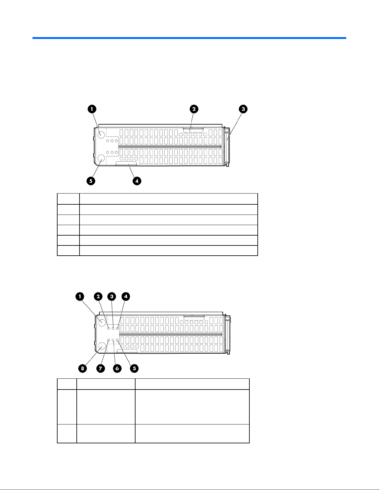
Front panel components
Item Description
1 Server B Power On/Standby button
2 Server B serial label pull tab
3 Server blade release lever
4 Server A serial label pull tab
5 Server A Power On/Standby button
Front panel LEDs
Item Description Status
1 Server B system
power LED
2 Server B UID LED Blue = Identified
Green = On
Amber = Standby (auxiliary power
available)
Off = No power available to server
Blue flashing = Active remote management
Component identification 6
Page 7
Item Description Status
Off = No active remote management
3 Server B health LED Green = Normal
Flashing = Booting
Amber = Degraded condition
Red = Critical condition
4 Server B NIC/IB link
and activity LED*
5 Server A NIC/IB link
and activity LED*
6 Server A health LED Green = Normal
7 Server A UID LED Blue = Identified
8 Server A system
power LED
* Actual NIC numbers depend on several factors, including the operating system installed on the server blade.
Green = Network linked
Green flashing = Network activity
Off = No link or activity
Green = Network linked
Green flashing = Network activity
Off = No link or activity
Flashing = Booting
Amber = Degraded condition
Red = Critical condition
Blue flashing = Active remote management
Off = No active remote management
Green = On
Amber = Standby (auxiliary power
available)
Off = No power available to server
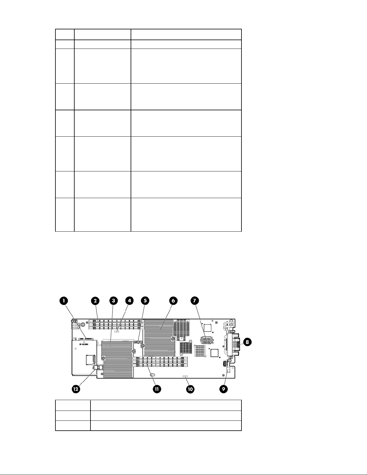
System board components
Server A system board components
Item Description
1 Hard drive connector
2 DIMM slots (processor 2)
Component identification 7
Page 8

Item Description
3 Processor socket 2 (populated)
4 Server A system board serial number label
5 System battery
6 Processor socket 1 (populated)
7 Signal connector
8 Enclosure connector
9 Power connector
10 System maintenance switch
11 DIMM slots (processor 1)
12 Internal USB connector
Server B system board components
Item Description
1 Hard drive connector
2 Processor socket 1 (populated)
3 System battery
4 DIMM slots (processor 2)
5 Server B system board serial number label
6 Processor socket 2 (populated)
7 Power connector
8 System maintenance switch
9 Signal connector
10 DIMM slots (processor 1)
11 Internal USB connector
DIMM slot numbering
For installation guidelines and population order, see "Memory options (on page 22)."
Component identification 8
Page 9
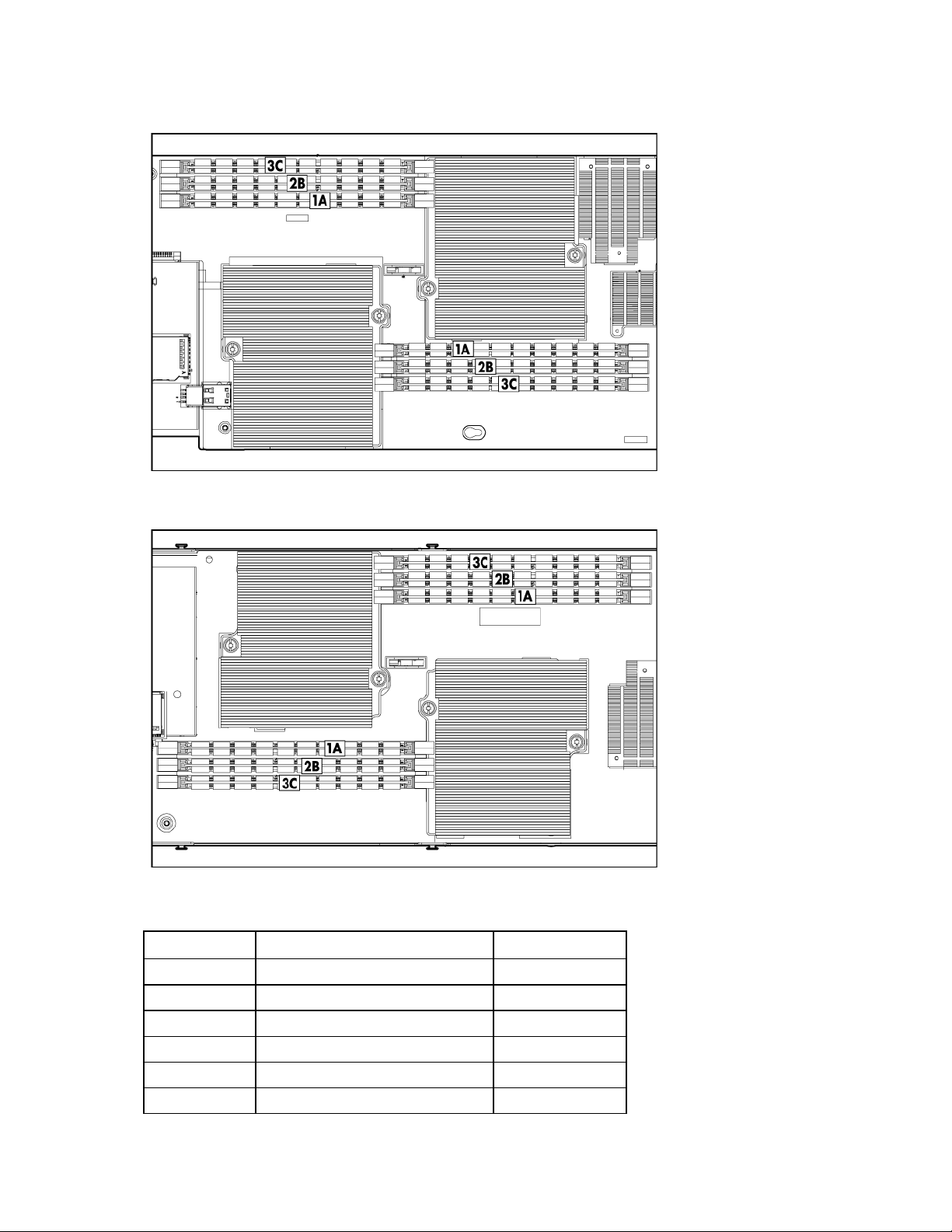
Server A DIMM slots
Server B DIMM slots
System maintenance switch
Position Function Default
1 iLO 3 security override Off
2 Configuration lock Off
3 Reserved Off
4 Reserved Off
5 Password disabled Off
6 Reset configuration Off
Component identification 9
Page 10

Position Function Default
7 Reserved Off
8 Reserved Off
When the system maintenance switch position 6 is set to the On position, the system is prepared to erase
all system configuration settings from both CMOS and NVRAM.
CAUTION: Clearing CMOS and/or NVRAM deletes configuration information. Be sure to
properly configure the server or data loss could occur.
Access components
CAUTION: The jackscrews control the unseating and seating of critical system connectors.
Failure to use the jackscrews to remove and install the server B assembly can cause the system
Item Description
1 Jackscrew 1
2 Jackscrew 2
3 T-15 Torx wrench
boards to fail.
Component identification 10
Page 11

Operations
Power up the server blade
The Onboard Administrator initiates an automatic power-up sequence when the server blade is installed.
If the default setting is changed, use one of the following methods to power up the server blade:
• Use an iLO 3 virtual power button selection for server A and server B.
• Press and release the server A and server B Power On/Standby button.
When the server blade goes from the standby mode to the full power mode, the system power LED
changes from amber to green.
For more information about the Onboard Administrator, see the enclosure setup and installation guide on
the HP website (http://www.hp.com/support
).
For more information about iLO 3, see "Integrated Lights-Out 3 technology (on page 37)."
Power down the server blade
Before powering down the server blade for any upgrade or maintenance procedures, perform a backup
of critical server data and programs on each server.
Depending on the Onboard Administrator configuration, use one of the following methods to power down
the server blade:
• Use the virtual power button selection through iLO 3 for both server A and server B.
This method initiates a controlled remote shutdown of applications and the OS before the server
blade enters standby mode.
• Press and release the server A and server B Power On/Standby buttons.
This method initiates a controlled shutdown of applications and the OS before the server blade
enters standby mode.
• Press and hold the server A and server B Power On/Standby buttons for more than 4 seconds to
force the server blade to shut down.
This method forces the server blade to enter standby mode without properly exiting applications and
the OS. It provides an emergency shutdown method in the event of a hung application.
CAUTION: To prevent damage to the server or the operating system, always power down
After initiating a virtual power down command, be sure that both server A and server B are in standby
mode by observing that the system power LEDs are amber.
both server A and server B before removing the server blade from the enclosure.
IMPORTANT: When the server blade is in standby mode, auxiliary power is still being
provided. To remove all power from the server blade, remove the server blade from the
enclosure.
Operations 11
 Loading...