

Page 1

HP Blade Server bh7800
Site Preparation Guide
June 2002
Manufacturing Part Number:
Version: Third Edition
USA
© Copyright 2002
Page 2

Legal Notices
The information in this document is subject to change without notice.
Hewlett-Packard makes no warranty of any kind with regard to this manual, including, but not limited to, the
implied warranties of merchantability and fitness for a particular purpose. Hewlett-Packard shall not be held
liable for errors contained herein or direct, indirect, special, incidental or consequential damages in
connection with the furnishing, performance, or use of this material.
Restricted Rights Legend. Use, duplication or disclosure by the U.S. Government is subject to restrictions as set forth in subparagraph (c) (1) (ii) of the Rights in Technical Data and Computer Software clause at DFARS 252.227-7013 for DOD agencies, and subparagraphs (c) (1) and (c) (2) of the Commercial Computer Software Restricted Rights clause at FAR 52.227-19 for other agencies.
HEWLETT-PACKARD COMPANY 3000 Hanover Street Palo Alto, California 94304 U.S.A.
Copyright Notices. ©copyright 1983-2002 Hewlett-Packard Company, all rights reserved.
Reproduction, adaptation, or translation of this document without prior written permission is prohibited,
except as allowed under the copyright laws.
ii
Page 3

1. HP Blade Server bh7800 Overview
Display Panel . . . . . . . . . . . . . . . . . . . . . . . . . . . . . . . . . . . . . . . . . . . . . . . . . . . . . . . . . . . . . . . . . . . . . . . 13
System Backplane . . . . . . . . . . . . . . . . . . . . . . . . . . . . . . . . . . . . . . . . . . . . . . . . . . . . . . . . . . . . . . . . . . . 14
Power Supplies . . . . . . . . . . . . . . . . . . . . . . . . . . . . . . . . . . . . . . . . . . . . . . . . . . . . . . . . . . . . . . . . . . . . . . 15
HP Server bc1100. . . . . . . . . . . . . . . . . . . . . . . . . . . . . . . . . . . . . . . . . . . . . . . . . . . . . . . . . . . . . . . . . . . . 16
Network Blade . . . . . . . . . . . . . . . . . . . . . . . . . . . . . . . . . . . . . . . . . . . . . . . . . . . . . . . . . . . . . . . . . . . . . . 17
Management LAN Blade . . . . . . . . . . . . . . . . . . . . . . . . . . . . . . . . . . . . . . . . . . . . . . . . . . . . . . . . . . . . . . 18
Management Blade . . . . . . . . . . . . . . . . . . . . . . . . . . . . . . . . . . . . . . . . . . . . . . . . . . . . . . . . . . . . . . . . . . 19
Fan Modules . . . . . . . . . . . . . . . . . . . . . . . . . . . . . . . . . . . . . . . . . . . . . . . . . . . . . . . . . . . . . . . . . . . . . . . . 20
Slot Blocker Assembly . . . . . . . . . . . . . . . . . . . . . . . . . . . . . . . . . . . . . . . . . . . . . . . . . . . . . . . . . . . . . . . . 21
Cable Management Tray . . . . . . . . . . . . . . . . . . . . . . . . . . . . . . . . . . . . . . . . . . . . . . . . . . . . . . . . . . . . . . 22
Front View . . . . . . . . . . . . . . . . . . . . . . . . . . . . . . . . . . . . . . . . . . . . . . . . . . . . . . . . . . . . . . . . . . . . . . . . . 23
Rear View . . . . . . . . . . . . . . . . . . . . . . . . . . . . . . . . . . . . . . . . . . . . . . . . . . . . . . . . . . . . . . . . . . . . . . . . . . 24
Air Flow . . . . . . . . . . . . . . . . . . . . . . . . . . . . . . . . . . . . . . . . . . . . . . . . . . . . . . . . . . . . . . . . . . . . . . . . . . . 25
Shipping Dimensions and Weights . . . . . . . . . . . . . . . . . . . . . . . . . . . . . . . . . . . . . . . . . . . . . . . . . . . . . . 27
2. General System and Facility Guidelines
Electrical Factors . . . . . . . . . . . . . . . . . . . . . . . . . . . . . . . . . . . . . . . . . . . . . . . . . . . . . . . . . . . . . . . . . . . . 30
Electrical Load Requirements (Circuit Breaker Sizing) LAHJ . . . . . . . . . . . . . . . . . . . . . . . . . . . . . . 30
Power Quality . . . . . . . . . . . . . . . . . . . . . . . . . . . . . . . . . . . . . . . . . . . . . . . . . . . . . . . . . . . . . . . . . . . . . 30
Distribution Hardware . . . . . . . . . . . . . . . . . . . . . . . . . . . . . . . . . . . . . . . . . . . . . . . . . . . . . . . . . . . . . . 31
Grounding Systems. . . . . . . . . . . . . . . . . . . . . . . . . . . . . . . . . . . . . . . . . . . . . . . . . . . . . . . . . . . . . . . . . 32
System Installation Guidelines . . . . . . . . . . . . . . . . . . . . . . . . . . . . . . . . . . . . . . . . . . . . . . . . . . . . . . . 35
Environmental Factors . . . . . . . . . . . . . . . . . . . . . . . . . . . . . . . . . . . . . . . . . . . . . . . . . . . . . . . . . . . . . . . 36
Computer Room Preparation . . . . . . . . . . . . . . . . . . . . . . . . . . . . . . . . . . . . . . . . . . . . . . . . . . . . . . . . . 36
Space Requirements . . . . . . . . . . . . . . . . . . . . . . . . . . . . . . . . . . . . . . . . . . . . . . . . . . . . . . . . . . . . . . . . 36
Floor Loading . . . . . . . . . . . . . . . . . . . . . . . . . . . . . . . . . . . . . . . . . . . . . . . . . . . . . . . . . . . . . . . . . . . . . 38
Cooling Requirements . . . . . . . . . . . . . . . . . . . . . . . . . . . . . . . . . . . . . . . . . . . . . . . . . . . . . . . . . . . . . . 39
Air Conditioning Ducts. . . . . . . . . . . . . . . . . . . . . . . . . . . . . . . . . . . . . . . . . . . . . . . . . . . . . . . . . . . . . . 42
Humidity Level . . . . . . . . . . . . . . . . . . . . . . . . . . . . . . . . . . . . . . . . . . . . . . . . . . . . . . . . . . . . . . . . . . . . 42
Dust and Pollution Control . . . . . . . . . . . . . . . . . . . . . . . . . . . . . . . . . . . . . . . . . . . . . . . . . . . . . . . . . . 42
Metallic Particulate Contamination . . . . . . . . . . . . . . . . . . . . . . . . . . . . . . . . . . . . . . . . . . . . . . . . . . . 43
Electrostatic Discharge (ESD) Prevention . . . . . . . . . . . . . . . . . . . . . . . . . . . . . . . . . . . . . . . . . . . . . . 43
Acoustics (noise reduction). . . . . . . . . . . . . . . . . . . . . . . . . . . . . . . . . . . . . . . . . . . . . . . . . . . . . . . . . . . 44
Contents
3. HP Blade Server bh7800 Power
HP Blade Server Initial Power-Up . . . . . . . . . . . . . . . . . . . . . . . . . . . . . . . . . . . . . . . . . . . . . . . . . . . . . . 46
Power Cords Supplied. . . . . . . . . . . . . . . . . . . . . . . . . . . . . . . . . . . . . . . . . . . . . . . . . . . . . . . . . . . . . . . 46
Chassis Power-Up . . . . . . . . . . . . . . . . . . . . . . . . . . . . . . . . . . . . . . . . . . . . . . . . . . . . . . . . . . . . . . . . . . 46
Blade Server Power-Down . . . . . . . . . . . . . . . . . . . . . . . . . . . . . . . . . . . . . . . . . . . . . . . . . . . . . . . . . . . 47
Connecting AC Power using a PDU . . . . . . . . . . . . . . . . . . . . . . . . . . . . . . . . . . . . . . . . . . . . . . . . . . . . . 48
A. System Specifications and Requirements
System Specifications . . . . . . . . . . . . . . . . . . . . . . . . . . . . . . . . . . . . . . . . . . . . . . . . . . . . . . . . . . . . . . . . 50
B. Power Plug Configuration
iii
Page 4

Contents
Cord Set Description . . . . . . . . . . . . . . . . . . . . . . . . . . . . . . . . . . . . . . . . . . . . . . . . . . . . . . . . . . . . . . . . . 58
C. Conversion Factors and Formulas
Conversion Factors. . . . . . . . . . . . . . . . . . . . . . . . . . . . . . . . . . . . . . . . . . . . . . . . . . . . . . . . . . . . . . . . . . . 62
Glossary . . . . . . . . . . . . . . . . . . . . . . . . . . . . . . . . . . . . . . . . . . . . . . . . . . . . . . . . . . . . . . . . . . . . 63
Index . . . . . . . . . . . . . . . . . . . . . . . . . . . . . . . . . . . . . . . . . . . . . . . . . . . . . . . . . . . . . . . . . . . . . . . 65
iv
Page 5

Figures
Figure 1-1. LCD Display Panel . . . . . . . . . . . . . . . . . . . . . . . . . . . . . . . . . . . . . . . . . . . . . . . . . . . . . . 13
Figure 1-2. bh7800 Backplane. . . . . . . . . . . . . . . . . . . . . . . . . . . . . . . . . . . . . . . . . . . . . . . . . . . . . . . 14
Figure 1-3. bh7800 Power Supplies (Chassis Rear View) . . . . . . . . . . . . . . . . . . . . . . . . . . . . . . . . . 15
Figure 1-4. HP Server bc1100 . . . . . . . . . . . . . . . . . . . . . . . . . . . . . . . . . . . . . . . . . . . . . . . . . . . . . . . 16
Figure 1-5. Network Blade. . . . . . . . . . . . . . . . . . . . . . . . . . . . . . . . . . . . . . . . . . . . . . . . . . . . . . . . . . 17
Figure 1-6. Management LAN Blade (shown with carrier) . . . . . . . . . . . . . . . . . . . . . . . . . . . . . . . . 18
Figure 1-7. Management Blade. . . . . . . . . . . . . . . . . . . . . . . . . . . . . . . . . . . . . . . . . . . . . . . . . . . . . . 19
Figure 1-8. bh7800 Fan Assemblies . . . . . . . . . . . . . . . . . . . . . . . . . . . . . . . . . . . . . . . . . . . . . . . . . . 20
Figure 1-9. bh7800 Caution Label shown with Slot Blocker Assembly . . . . . . . . . . . . . . . . . . . . . . 21
Figure 1-10. bh7800 Racking for HP Rack System/E Cabinet Showing Cable Tray . . . . . . . . . . . . 22
Figure 1-11. bh7800 Front View . . . . . . . . . . . . . . . . . . . . . . . . . . . . . . . . . . . . . . . . . . . . . . . . . . . . . 23
Figure 1-12. bh7800 Rear View . . . . . . . . . . . . . . . . . . . . . . . . . . . . . . . . . . . . . . . . . . . . . . . . . . . . . . 24
Figure 1-13. bh7800 Cooling Airflow (Chassis Rear View) . . . . . . . . . . . . . . . . . . . . . . . . . . . . . . . . 25
Figure 1-14. bh7800 Cooling Airflow (Chassis Side View). . . . . . . . . . . . . . . . . . . . . . . . . . . . . . . . . 26
Figure 2-1. Raised Floor Metal Strip Ground System . . . . . . . . . . . . . . . . . . . . . . . . . . . . . . . . . . . . 34
Figure A-1. Power Supply Label . . . . . . . . . . . . . . . . . . . . . . . . . . . . . . . . . . . . . . . . . . . . . . . . . . . . . 51
Figure B-1. Cord Sets. . . . . . . . . . . . . . . . . . . . . . . . . . . . . . . . . . . . . . . . . . . . . . . . . . . . . . . . . . . . . . 58
Figure B-2. Male Receptacle to Female Plug . . . . . . . . . . . . . . . . . . . . . . . . . . . . . . . . . . . . . . . . . . . 58
Figure B-3. Male Plug Types . . . . . . . . . . . . . . . . . . . . . . . . . . . . . . . . . . . . . . . . . . . . . . . . . . . . . . . . 59
v
Page 6

Figures
vi
Page 7

Tab les
Table 1. Publication History . . . . . . . . . . . . . . . . . . . . . . . . . . . . . . . . . . . . . . . . . . . . . . . . . . . . . . . . 10
Table 1-1. bh7800 Server Weights and Dimensions as Shipped on a Pallet . . . . . . . . . . . . . . . . . . . 27
Table 2-1. Floor Loading Terminology. . . . . . . . . . . . . . . . . . . . . . . . . . . . . . . . . . . . . . . . . . . . . . . . . 38
Table 3-1. Server Chassis Power Cords. . . . . . . . . . . . . . . . . . . . . . . . . . . . . . . . . . . . . . . . . . . . . . . . 46
Table 3-2. PDU and UPS Power Cords . . . . . . . . . . . . . . . . . . . . . . . . . . . . . . . . . . . . . . . . . . . . . . . . 48
Table A-1. bh7800 Specifications. . . . . . . . . . . . . . . . . . . . . . . . . . . . . . . . . . . . . . . . . . . . . . . . . . . . . 50
Table A-2. Environmental Conditions. . . . . . . . . . . . . . . . . . . . . . . . . . . . . . . . . . . . . . . . . . . . . . . . . 52
Table A-3. Weight and Dimensions . . . . . . . . . . . . . . . . . . . . . . . . . . . . . . . . . . . . . . . . . . . . . . . . . . . 52
Table A-4. Power Dissipation (Theoretical Maximum) . . . . . . . . . . . . . . . . . . . . . . . . . . . . . . . . . . . 52
Table A-5. Power Dissipation and Air Conditioning Requirement Summary . . . . . . . . . . . . . . . . . 53
Table A-6. Power Dissipation and Air Conditioning Requirement Example . . . . . . . . . . . . . . . . . . 54
vii
Page 8

Tables
viii
Page 9

Preface
Before preparing your site for the HP Blade Server bh7800, familiarize yourself with the components that
comprise the bh7800. Use the following reference to determine where to start.
Page 10

Book Layout
• Chapter 1 – provides an overview of the bh7800 components, cooling air flow, shipping dimensions and
weight and CFM value.
• Chapter 2 – provides specific information ensuring the site is ready when the bh7800 arrives. Voltage
fluctuations, grounding and floor loading are some of the topics covered.
• Chapter 3 – covers how to power up the bh7800 and how to power down the bh7800. Power distribution
information and power cords required are specified.
• Appendix A – provides specifications and requirements necessary to ensure the bh7800 environment
provided is suitable for operating the bh7800.
• Appendix B – provides power plug configuration information for the male and female end of the cord set.
• Appendix C – provides conversion factors and formulas used for determining site environment
requirements.
• Glossary – provides a list of terms most commonly used in this manual.
• Index - a quick look up table for common terms and components used in this guide.
Publication History
The Site Preparation guide was never assigned a manufacturing part number. The method for tracking
revisions will be this table.
Table 1 Publication History
Edition Comments
First December 2001 release. CD-ROM, EPSS Web site, and http://docs.hp.com delivery mechanisms.
Second April 2002 release. CD-ROM, EPSS Web site, and http://docs.hp.com delivery mechanisms.
Power dissipation values in appendices were revised.
Third June 2002 release. CD-ROM, EPSS Web site, and http://docs.hp.com delivery mechanisms.
Conversion from MS Word to Framemaker 6.0 to meet Section 508 compliance. Enhanced
graphics and illustrations added.
10
Page 11

1 HP Blade Server bh7800 Overview
The HP Blade Server bh7800 provides customers with a single chassis that can house up to 16 functionally
separate servers, controlled by one management blade. The form factor for all the blades uses the
CompactPCI standard. The chassis mounts in a standard 19-inch EIA rack, in either a two column or four
Chapter 1
11
Page 12

HP Blade Server bh7800 Overview
column style rack. Hewlett-Packard Company offers kits for either type rack. The chassis provides slots in the
front and rear for installation of server blades, and network blades. Each side accommodates 18 blades and
can house up to eight server blades per side.
This chapter provides a high level overview of the various components that comprise the blade server. It is not
the intention of this chapter to cover how to operate the blade server.
12
Chapter 1
Page 13

HP Blade Server bh7800 Overview
Display Panel
Display Panel
The bh7800 display panel provides the controls and indicators commonly used when operating the bh7800.
There are two LCD display assemblies on the bh7800. Remote control over a network is another method used
to operate the bh7800. One display is in the front, just above the card cage. The other is in the rear, just above
the card cage. Both show identical data and are visible regardless of which side of the product you are on. The
rear display assembly is hinged so that it can be lifted up out of the way for access to the hot swap fan
modules. The LCD display panels allow most initialization and system monitoring functions to be performed
without connecting via Telnet or directly connecting to the management blade’s serial port. The display panel
is shown in Figure 1-1.
Figure 1-1 LCD Display Panel
Chapter 1
13
Page 14
HP Blade Server bh7800 Overview
System Backplane
System Backplane
The passive system backplane is centrally located in the bh7800 to accommodate front and rear card cages. 18
CompactPCI slots are available on each side with up to five connectors per slot. For the CompactPCI
standard, the lower two connectors are used for CompactPCI standard connections, and the upper three
connectors are for custom user applications. Additionally, the rear of the backplane has four power
connections (two for each power supply). The front of the backplane also contains the fan harness connector
and two LCD display cable connections. All connectors used on the backplane are press-fit. No special tool is
needed to insert or remove the connectors.
Figure 1-2 bh7800 Backplane
14
Chapter 1
Page 15

HP Blade Server bh7800 Overview
Power Supplies
Power Supplies
Each power supply uses two DC connectors that plug into the backplane, and an AC connector brings line
power into the unit. Two power supplies and two power cords ship with the system.
Each supply contains an internal fan for cooling. In the rear of each supply are two insertion/extraction
handles and latch assemblies for ease of inserting or removing each power supply. Two captive screws secure
each power supply to the system chassis.
A solid green LED indicates normal operation for either power supply. A solid yellow LED indicates a power
supply failure. Power supplies are hot swappable.
Figure 1-3 bh7800 Power Supplies (Chassis Rear View)
Chapter 1
15
Page 16

HP Blade Server bh7800 Overview
HP Server bc1100
HP Server bc1100
Up to 16 1 slot IA-32 server blades can be inserted in the bh7800 chassis. The 1 slot, 1way IA-32 blade server
is a self-contained system. It includes all memory, processor, firmware, I/O adapters, and core I/O required to
install the operating system. The board is CompactPCI and hot plug compliant and operates as a
CompactPCI master in the host slot. It is also Network Equipment Building Standards (NEBS) compliant.
Some I/O connections will be driven through the backplane and some local connections will be available from
the front panel.
A daughter board known as the Remote Management Card (RMC) provides LAN-based system console access
as well as remote system management functions. LAN-based access to the system console via Telnet is
provided to initially configure parameters stored in firmware on the blade. Remote system management
functions include power, reboot and inventory control.
Figure 1-4 HP Server bc1100
16
Chapter 1
Page 17

HP Blade Server bh7800 Overview
Network Blade
Network Blade
The network blade is a 24-port 10/100 switch with a gigabit uplink connection. The blade provides 16 of the
24 ports to the backplane, and 8 remaining ports out to the bulkhead. In addition, the network blade comes in
three uplink options: Tx (copper), Sx (short-wave optical), or Lx (long-wave optical).
The bh7800 system must contain one network blade, but can optionally contain two. The backplane actually
contains two separate LANs, LAN-A and LAN-B, so that a second blade provides backup protection for the
LAN segment.
The uplink connection aggregates all communications in the bh7800. This gigabit connection aggregates the
traffic from all 16 ports.
The blade may be hot swapped without taking down a live system. Of course, if only one switch is in the
cabinet, all external communications cease while the blade is being swapped. With a second switch in the
chassis, external communications are only interrupted on the LAN connected to the corresponding switch
being hot swapped. The switch in front slot 12 corresponds to LAN-A and the switch in rear slot 13
corresponds to LAN-B.
Figure 1-5 Network Blade
Chapter 1
17
Page 18
HP Blade Server bh7800 Overview
Management LAN Blade
Management LAN Blade
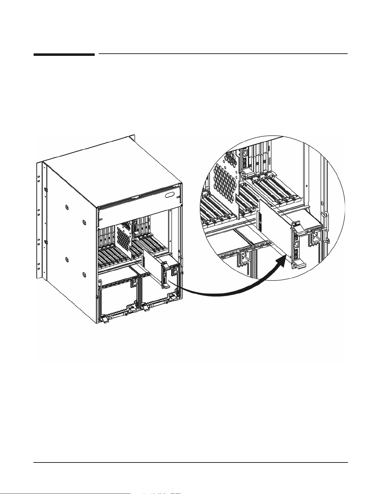
The two Rear Transition Modules (RTMs) are unique in the bh7800 product. The RTM is a pseudo standard
CompactPCI solution. Each RTM is a 3U blade rather than a 6U blade. CompactPCI card format and the
bulkhead is not a CompactPCI standard. A custom carrier holds each PCA in the bh7800 backplane. The
custom card guide is inserted in a dedicated location in the rear card cage. The RTM is more commonly
referred to as the management LAN blade.
Figure 1-6 Management LAN Blade (shown with carrier)
18
Chapter 1
Page 19

HP Blade Server bh7800 Overview
Management Blade
Management Blade
The bh7800 includes a management blade that allows remote and local management of the individual server
and network blades. The blade monitors the chassis environment such as power, temperature, and overall
server blade health. The blade can be accessed via a serial connection on the chassis or it can be accessed via
the control and management LAN.
The blade provides management support for the console LAN management signals. Provision for control of
the console LAN management signals for the sixteen IA-32 server blades or two LAN switches is in the 38 slot
chassis.
Figure 1-7 Management Blade
Chapter 1
19
Page 20

HP Blade Server bh7800 Overview
Fan Modules
Fan Modules
There are two fan module assemblies in the bh7800. They are hot swap modules. Each fan module has an
LED to indicate fan failure. Also, each fan can go into the fan module only one way due to the length and
location of the fan cable with its blind mate connector. Once each fan module is securely seated in the chassis,
two screws are tightened to secure each fan and prevent it from backing out of the chassis due to vibration.
Figure 1-8 bh7800 Fan Assemblies
20
Chapter 1
Page 21

HP Blade Server bh7800 Overview
Slot Blocker Assembly
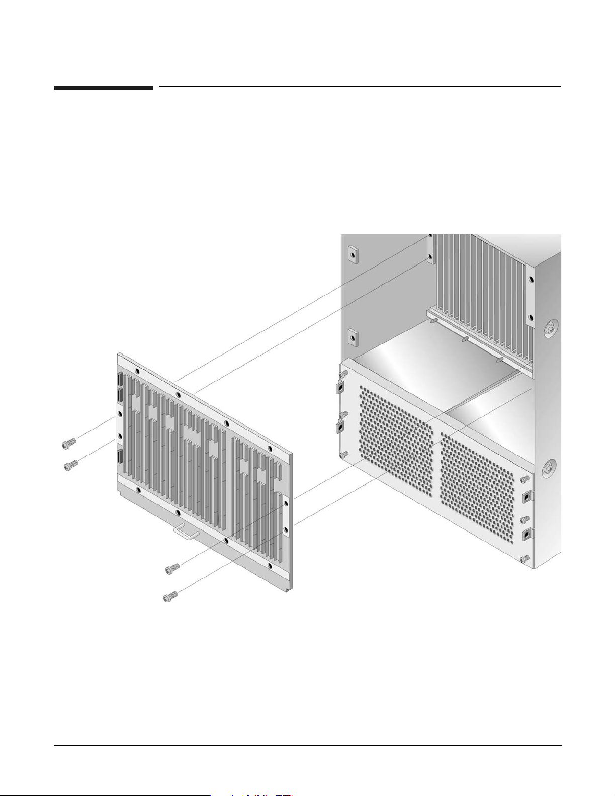
Slot Blocker Assembly
The bh7800 uses a closed, pressurized cooling system. Fans draw air in the bottom at the front of the chassis,
direct it upwards across the front blades, over the top of the backplane, downwards over the rear blades and
into the power supplies where it exits out the back of the bh7800.
Any slot that isn’t occupied by a blade must contain a slot blocker to channel cool air in the proper direction to
maintain the cooling system pressure. A caution label on the chassis (bottom figure) indicates how serious
this requirement is.
Figure 1-9 bh7800 Caution Label shown with Slot Blocker Assembly
Chapter 1
21
Page 22

HP Blade Server bh7800 Overview
Cable Management Tr ay
Cable Management Tray
The ½ EIA unit high (1/2U) cable management tray provides a channel for cables and helps prevent the
accidental disconnection of cables from their respective blades. The tray is provided for HP Rack System/E
four post cabinets, Nortel four post cabinets and Chatsworth two post cabinets. The tray allows data cables to
be securely attached to the chassis and to maintain the critical bend radius associated with high speed data
cables.
Figure 1-10 bh7800 Racking for HP Rack System/E Cabinet Showing Cable Tray
22
Cable Management Tray
Chapter 1
Page 23

HP Blade Server bh7800 Overview
Front View
Front View
The components available at the front of this 13 EIA unit high (13U) server are
• Eighteen individual CompactPCI slots supporting defined configurations for 1 slot and 2 slot PCA’s
• One front LCD display panel
• The system backplane is removable from the front and is centrally located in the chassis
• Front cable management bracket (not shown)
Figure 1-11 bh7800 Front View
Chapter 1
23
Page 24

HP Blade Server bh7800 Overview
Rear View
Rear View
The components available at the rear of this 13 EIA unit high (13U) server are
• Two hot swap N+1 power supplies
• Two hot swap N+1 fan modules (hidden behind the rear panel display)
• Eighteen individual CompactPCI slots supporting defined configurations for 1 slot and 2 slot PCAs.
• One rear LCD display panel
• Rear cable management bracket (not shown)
Figure 1-12 bh7800 Rear View
24
Chapter 1
Page 25

Air Flow
Figure 1-13 bh7800 Cooling Airflow (Chassis Rear View)
HP Blade Server bh7800 Overview
Air Flow
The bh7800 utilizes a front to back cooling scheme. Four 150mm diameter 48V DC fans cool the system, one
in each power supply and two in independent carriers. Refer to Appendix A for System Specifications. Air
enters the vent along the lower front surface of the chassis and passes through the front sections of the power
Chapter 1
25
Page 26

HP Blade Server bh7800 Overview
Air Flow
supplies and up through the front card cage. Air then passes over the top of the backplane, through the top
rear fans and down through the rear card cage. It travels through the rear sections of the power supplies and
out through the rear power supply fans.
Figure 1-14 bh7800 Cooling Airflow (Chassis Side View)
Air Intake Temperature
The recommended air intake temperature for the bh7800 server is between 68 degrees F and 77 degrees F (25
degrees C and 30 degrees C) at 225 CFM.
26
Chapter 1
Page 27

HP Blade Server bh7800 Overview
Shipping Dimensions and Weights
Shipping Dimensions and Weights
Table 1-1 lists the dimensions and weights of the bh7800 server with the shipping pallet.
Table 1-1 bh7800 Server Weights and Dimensions as Shipped on a Pallet
Equipment Width (cm) Depth/Length (cm) Height (cm) Weight (kg)
bh7800 server
on shipping
ab
pallet
a. Shipping box, pallet and container add approximately 23 lbs to the total system
weight.
b. Specifications given in Table 1-1 are for a fully configured system.
21.25 inches (53.98 cm)
30.50 inches (77.47 cm)
29.38 inches (74.63 cm)
203 lbs (92.08 kg)
Chapter 1
27
Page 28

HP Blade Server bh7800 Overview
Shipping Dimensi ons and We ights
28
Chapter 1
Page 29

2 General System and Facility Guidelines
This chapter provides general computer facility guidelines for planning and preparing the site. Careful site
planning and preparation ensures trouble-free installation and reliable operation of HP servers. Factors that
may contribute to less than optimal equipment operation are also highlighted. Refer to Appendix A for more
information on guidelines specific to the bh7800.
Chapter 2
29
Page 30

General System and Facility Guidelines
Electrical Factor s
Electrical Factors
NOTE Electrical practices and suggestions in this guide are based on North American practices. For
countries and areas outside North America, local electrical codes will take precedence over
North American electrical codes.
An example would be the recommendation that the PE (protective earthing) conductor be green
with yellow stripes. This requirement is a North American directive and does not override the
local code requirements for a country or area outside North America.
Local Authority Has Jurisdiction (LAHJ) and should make the final decision regarding
adherence to country-specific or area-specific electrical codes and guidelines.
Throughout this chapter, the LAHJ acronym will be used to indicate Local Authority Has Jurisdiction.
Proper design and installation of a power distribution system for a HP server requires specialized skills.
Those responsible for this task must have a thorough knowledge and understanding of appropriate electrical
codes and the limitations of the power systems for computer and data processing equipment.
In general, a well-designed power distribution system exceeds the requirements of most electrical codes. A
good design, when coupled with proper installation practices, produces the most trouble-free operation.
A detailed discussion of power distribution system design and installation is beyond the scope of this
document. However, electrical factors relating to power distribution system design and installation must be
considered during the site preparation process.
The electrical factors discussed in this section are:
• Electrical load requirements (circuit breaker sizing)
• Power quality
• Distribution hardware
• Grounding Systems
• System installation guidelines
Electrical Load Requirements (Circuit Breaker Sizing) LAHJ
Appendix A summarizes electrical power load (KVA input) requirements for this server but additional
capacity should be added for equipment upgrading or expansion.
It is a good practice to derate power distribution systems for one or more of the following reasons:
• Circuit protection devices should be rated at 20% above the systems root-mean-square (RMS) current
ratings to avoid nuisance tripping from load shifts or power transients.
• Safety agencies derate most power connectors to 80% of their RMS current ratings.
Power Quality
HP equipment is designed to operate over a wide range of voltages and frequencies. However, damage can
occur if these ranges are exceeded. Severe electrical disturbances can exceed the design specifications of the
equipment.
30
Chapter 2
Page 31

General System and Facility Guidelines
Electrical Factors
Sources of Volt age Fluc tuations
Voltage fluctuations, sometimes called glitches, affect the quality of electrical power. Common sources of these
fluctuations are:
• Fluctuations occurring within the facility’s distribution system
• Utility service low-voltage conditions (such as sags or brownouts)
• Wide and rapid variations in input voltage levels
• Wide and rapid variations in input power frequency
• Electrical storms
• Large inductive sources (such as motors and welders)
• Faults in the distribution system wiring (such as loose connections)
• Microwave, radar, radio, or cell phone transmissions
Power System Protection
Computer systems can be protected from the sources of many of these electrical disturbances by using:
• A dedicated power distribution system
• Power conditioning equipment
• Over- and under-voltage detection and protection circuits
• Screening to cancel out the effects of undesirable transmissions
• Lightning arresters on power cables to protect equipment against electrical storms
Precautions have been taken during power distribution system design to provide immunity to power outages
of less than one cycle. However, testing cannot conclusively rule out loss of service. Therefore, adherence to
the following guidelines provides the best possible performance of power distribution systems for HP server
equipment:
• Dedicated power source—Isolates server power distribution system from other circuits in the facility.
• Missing-phase and low-voltage detectors—Shuts equipment down automatically when a severe power
disruption occurs. For peripheral equipment, these devices are recommended but optional.
• Online Uninterruptible Power Supply (UPS)—Keeps input voltage to devices constant and should be
considered if outages of one-half cycle or more are common.
Refer to qualified contractors or consultants for each situation.
Distribution Hardware
This section describes wire selection and the types of raceways (electrical conduits) used in the distribution
system.
Wire Selection
Use copper conductors instead of aluminum, as aluminum’s coefficient of expansion differs significantly from
that of other metals used in power hardware. Because of this difference, aluminum conductors can cause
connector hardware to work loose, overheat, and fail.
Chapter 2
31
Page 32

General System and Facility Guidelines
Electrical Factor s
Raceway Systems (Electrical Conduits) LAHJ
Raceways (electrical conduits) form part of the protective ground path for personnel and equipment.
Raceways protect the wiring from accidental damage and also provide a heatsink for the wires.
Any of the following types may be used:
• Electrical Metallic Tubing (EMT) thin-wall tubing
• Rigid (metal) conduit
• Liquidtight with RFI shield grounded (most commonly used under raised floors)
Building Distribution
All building feeders and branch circuitry should be in rigid metallic conduit with proper connectors (to
provide ground continuity). Conduit that is exposed and subject to damage should be constructed of rigid
galvanized steel.
Grounding Systems
Power Distribution Safety Grounding LAHJ
The power distribution safety grounding system consists of connecting various points in the power
distribution system to earth ground using green (green/yellow) wire ground conductors. Having these ground
connections tied to metal chassis parts that may be touched by computer room personnel protects them
against shock hazard from current leakage and fault conditions.
Power distribution systems consist of several parts. Hewlett-Packard recommends that these parts be solidly
interconnected to provide an equipotential ground to all points.
Main Building Electrical Ground
The main electrical service entrance equipment should have an earth ground connection, as required by
applicable codes. Connections such as a grounding rod, building steel, or a conductive type service pipe
provide an earth ground.
Electrical Conduit Ground
All electrical conduits should be made of rigid metallic conduit that is securely connected together or bonded
to panels and electrical boxes, so as to provide a continuous grounding system.
Power Panel Ground
Each power panel should be grounded to the electrical service entrance with green (green/yellow) wire ground
conductors. The green (green/yellow) wire ground conductors should be sized per applicable codes (based on
circuit over current device ratings).
NOTE The green wire ground conductor mentioned above might be a black wire marked with green
tape. LAHJ
Computer S afe ty G round
Ground all computer equipment with the green (green/yellow) wire included in the branch circuitry. The
green (green/yellow) wire ground conductors should be connected to the appropriate power panel and should
be sized per applicable codes (based on circuit over current device ratings).
32
Chapter 2
Page 33

General System and Facility Guidelines
Electrical Factors
Dual Power Source Grounding
When dual power sources are utilized, strong consideration should be given to measure voltage potentials.
The use of dual power might create an electrical potential that can be hazardous to personnel and might
cause performance issues for the equipment.
Dual power sources might originate from two different transformers or two different UPS devices. Voltage
potentials from ground pin to ground pin of these sources should be measured and verified to be at or near 0.0
volts. Voltage levels that deviate or are measured above 3.0 volts should be further investigated. Increased
voltages might be hazardous to personnel, and should be further investigated.
Cabinet Perform anc e Grounding (Hig h Frequency Groun d)
Signal interconnects between system cabinets require high frequency ground return paths. Connect all
cabinets to site ground.
NOTE In some cases power distribution system green (green/yellow) wire ground conductors are too
long and inductive to provide adequate high frequency ground return paths. Therefore, a
ground strap (customer-supplied) should be used for connecting the system cabinet to the
site-grounding grid (customer-supplied). When connecting this ground, ensure that the raised
floor is properly grounded for high frequency.
Power panels located in close proximity to the computer equipment should also be connected to site grounding
grid. Methods of providing a sufficiently high frequency ground grid are described in the next sections.
Raised Floo r “Hi gh Frequency Noise” Grounding
If a raised floor system is used, install a complete signal-grounding grid for maintaining equal potential over
a broad band of frequencies. The grounding grid should be connected to the equipment cabinet and electrical
2
service entrance ground at multiple connection points using a minimum #6 AWG (16mm
) wire ground
conductor. Figure 2-1 illustrates a metallic strip grounding system.
NOTE Regardless of the grounding connection method used, the raised floor should be grounded as an
absolute safety minimum.
Hewlett-Packard recommends the following approaches:
• Excellent - Add a grounding grid to the subfloor. The grounding grid should be made of copper strips
mounted to the subfloor. The strips should be 0.032 in. (0.08 cm) thick and a minimum of 3.0 in. (8.0 cm)
wide. Connect each pedestal to four strips using 1/4 in. (6.0 mm) bolts tightened to the manufacturer’s
torque recommendation.
• Better - A grounded #6 AWG minimum copper wire grid mechanically clamped to floor pedestals and
properly bonded to the building/site ground.
• Good - Use the raised floor structure as a ground grid. In this case, the floor must be designed as a ground
grid with bolted down stringers and corrosion resistive plating (to provide low resistance and attachment
points for connection to service entrance ground and HP server equipment). The use of conductive floor
tiles with this style of grid further enhances ground performance. The structure needs to be mechanically
bonded to a known good ground point.
Chapter 2
33
Page 34

General System and Facility Guidelines
Electrical Factor s
Equipment Grounding Implementation Details
Connect all Hewlett-Packard equipment cabinets to the site ground grid as follows:
1. Attach one end of each ground strap to the applicable cabinet ground lug.
2. Attach the other end to the nearest pedestal base (raised floor) or cable trough ground point (nonraised
floor).
3. Check that the braid contact on each end of the ground strap consists of a terminal and connection
hardware (a 1/4-in. (6.0 mm) bolt, nuts, and washers).
4. Check that the braid contact connection points are free of paint or other insulating material and treated
with a contact enhancement compound (similar to Burndy Penetrox).
Figure 2-1 Raised Floor Metal Strip Ground System
34
Chapter 2
Page 35

General System and Facility Guidelines
Electrical Factors
System Installation Guidelines
This section contains information about installation practices. Some common pitfalls are highlighted. Wiring
connections and data communications cable installations are discussed.
NOTE In domestic installations, the proper receptacles should be installed prior to the arrival of
Hewlett-Packard equipment. Refer to the appropriate installation guide for installation
procedures.
Wiring Connections
Expansion and contraction rates vary among different metals. Therefore, the integrity of an electrical
connection depends on the restraining force applied. Connections that are too tight, compress or deform the
hardware and cause it to weaken. This usually leads to high impedance preventing circuit breakers from
tripping when needed or can contribute to a buildup of high frequency noise.
CAUTION Connections that are too loose or too tight can have a high impedance that cause serious
problems, such as erratic equipment operation. A high impedance connection overheats and
sometimes causes fire or high temperatures that can destroy hard-to-replace components such
as distribution panels or system bus bars.
Wiring connections must be properly torqued. Many equipment manufacturers specify the proper connection
torque values for their hardware.
Ground connections must only be made on a conductive, nonpainted surface. When equipment vibration is
present, lock washers must be used on all connections to prevent connection hardware from working loose.
Data Communications Cables
Power transformers create high-energy fields in the form of electromagnetic interference (EMI). Heavy foot
traffic can create electrostatic discharge (ESD) that can damage electronic components. Route data
communications cables away from these areas. Use shielded data communications cables that meet approved
industry standards to reduce the effects of external fields.
Chapter 2
35
Page 36

General System and Facility Guidelines
Environmental Factors
Environmental Factors
The environmental factors discussed in this section are:
• Computer Room Preparation
• Space Requirements
• Floor Loading
• Cooling Requirements
• Air Conditioning Ducts
• Humidity Level
• Dust and Pollution Control
• Metallic Particulate Contamination
• Electrostatic Discharge (ESD) Prevention
• Acoustics (noise reduction)
Computer Room Preparation
The following guidelines are recommended when preparing a computer room for a HP server.
• Locate the computer room away from the exterior walls of the building to avoid the heat gain from
windows and exterior wall surfaces.
• When exterior windows are unavoidable, use windows that are double or triple glazed and shaded to
prevent direct sunlight from entering the computer room.
• Maintain the computer room at a positive pressure relative to surrounding spaces.
• Use a vapor barrier installed around the entire computer room envelope to restrain moisture migration.
• Caulk and vapor seal all pipes and cables that penetrate the envelope.
• Use at least a 12-inch raised floor for minimum favorable room air distribution system (underfloor
distribution).
• Ensure a minimum clearance of 12 inches between the top of the server cabinet and the ceiling to allow
for return airflow and ensure that all ceiling tiles are in place.
• Allow 18 inches (or local code minimum clearance) from the top of the server cabinet to the fire sprinkler
heads.
Space Requirements
This section contains information about space requirements for a HP server. This data should be used as the
basic guideline for space plan developments. Other factors, such as airflow, lighting, and equipment space
requirements must also be considered.
Delivery Space Requirements
There should be enough clearance to move equipment safely from the receiving area to the computer room.
Permanent obstructions, such as pillars or narrow doorways, can cause equipment damage.
36
Chapter 2
Page 37

General System and Facility Guidelines
Environmental Factors
Delivery plans should include the possible removal of walls or doors. The physical dimensions for applicable
computers and peripheral equipment are summarized in Appendix A.
Operational Space Requirements
Other factors must be considered along with the basic equipment dimensions. Reduced airflow around
equipment causes overheating, which can lead to equipment failure. Therefore, the location and orientation of
air conditioning ducts, as well as airflow direction, are important. Obstructions to equipment intake or
exhaust airflow must be eliminated.
The locations of lighting fixtures and utility outlets affect servicing operations. Plan equipment layout to take
advantage of lighting and utility outlets. Do not forget to include clearance for opening and closing equipment
doors.
Clearance around and above the cabinets must be provided for proper cooling airflow through the equipment.
The service area space requirements, outlined in Appendix A, are minimum dimensions. If other equipment is
located so that it exhausts heated air near the cooling air intakes of the computer system cabinets, larger
space requirements are needed to keep ambient air intake to the computer system cabinets within the
specified temperature and humidity ranges.
Space planning should also include the possible addition of equipment or other changes in space
requirements. Equipment layout plans should also include provisions for the following:
• Channels or fixtures used for routing data cables and power cables
• Access to air conditioning ducts, filters, lighting, and electrical power hardware
• Power conditioning equipment
• Cabinets for cleaning materials
• Maintenance area and spare parts
Floor Plan Grid
A floor plan grid is helpful for planning the location of equipment in the computer room. In addition to its use
for planning, a floor plan grid should also be considered when planning the locations of the following items:
• Air conditioning vents
• Lighting fixtures
• Utility outlets
• Doors
• Access areas for power wiring and air conditioning filters
• Equipment cable routing
Chapter 2
37
Page 38

General System and Facility Guidelines
Environmental Factors
Floor Loading
The computer room floor must be able to support the total weight of the installed computer system as well as
the weight of the individual cabinets as they are moved into position.
Floor loading is usually not an issue in nonraised floor installations. The information presented in this section
is directed toward raised floor installations.
NOTE An appropriate floor system consultant should verify any floor system under consideration for a
HP server installation.
Raised Floor Loading
Raised floor loading is a function of the manufacturer’s load specification and the positioning of the
equipment relative to the raised floor grid. While Hewlett-Packard cannot assume responsibility for
determining the suitability of a particular raised floor system, it does provide information and illustrations
for the customer or local agencies to determine installation requirements.
The following guidelines are recommended:
• Because many raised floor systems do not have grid stringers between floor stands, the lateral support for
the floor stands depends on adjacent panels being in place. To avoid compromising this type of floor
system while gaining under floor access, remove only one floor panel at a time.
• Larger floor grids (bigger panels) are generally rated for lighter loads.
CAUTION Do not position or install any equipment cabinets on the raised floor system until you have
carefully examined it to verify that it is adequate to support the appropriate installation.
Floor Loading Terms
Table 2-1 defines floor-loading terms.
Table 2-1 Floor Loading Terminology
Term Definitio n
Dead load The weight of the raised panel floor system, including the under structure.
2
(kg/m2).
2
(kg/m2).
2
(6.45 cm2) area at the panel’s
Live load
Concentrated load
Expressed in lb/ft
The load that the floor system can safely support. Expressed in lb/ft
The load that a floor panel can support on a one-inch
weakest point (typically the center of the panel), without the surface of the panel
deflecting more than a predetermined amount.
Ultimate load The maximum load (per floor panel) that the floor system can support without
failure. Failure expressed by floor panel(s) breaking or bending. Ultimate load is
usually stated as load per floor panel.
Rolling load The load a floor panel can support (without failure) when a wheel of specified
diameter and width is rolled across the panel.
38
Chapter 2
Page 39

Table 2-1 Floor Loading Terminology (Continued)
Term Definitio n
General System and Facility Guidelines
Environmental Factors
Average floor load
Computed by dividing total equipment weight by the area of its footprint. This
2
value is expressed in lb/ft
(kg/m2).
Cooling Requirements
Air conditioning equipment requirements and recommendations are described in the following sections.
Appendix A summarizes air conditioning requirements for this HP server.
Basic Air Conditioning Equipment Requirement
The cooling capacity of the installed air conditioning equipment for the computer room should be sufficient to
offset the computer equipment dissipation loads, as well as any space envelope heat gain. This equipment
should include:
• Air filtration
• Cooling or dehumidification
• Humidification
• Reheating
•Air distribution
• System controls adequate to maintain the computer room within the specified operating ranges of this HP
Server.
Lighting and personnel must also be included. For example, a person dissipates about 450 BTUs per hour
while performing a typical computer room task.
Air Conditioning System Guidelines
The following guidelines are recommended when designing an air conditioning system and selecting the
necessary equipment:
• The air conditioning system that serves the computer room should be capable of operating 24 hours a day,
365 days a year. It should also be independent of other systems in the building.
• Consider the long-term value of computer system availability, redundant air conditioning equipment or
capacity.
• The system should be capable of handling any future computer system expansion.
• Air conditioning equipment air filters should have a minimum rating of 45% (based on “ASHRAE
Standard 52-76, Dust Spot Efficiency Test”).
• Introduce only enough outside air into the system to meet building code requirements (for human
occupancy) and to maintain a positive air pressure in the computer room.
Air Conditioning System Types
The following three air conditioning system types are listed in order of preference:
• Complete self-contained package unit(s) with remote condenser(s). These systems are available with up or
down discharge and are usually located in the computer room.
Chapter 2
39
Page 40

General System and Facility Guidelines
Environmental Factors
• Chilled water package unit with remote chilled water plant. These systems are available with up or down
discharge and are usually located in the computer room.
• Central station air handling units with remote refrigeration equipment. These systems are usually
located outside the computer room.
40
Chapter 2
Page 41

General System and Facility Guidelines
Environmental Factors
Basic Air Distribution Systems
A basic air distribution system includes supply air and return air.
An air distribution system should be zoned to deliver an adequate amount of supply air to the cooling air
intake vents of the computer system equipment cabinets. Supply air temperature should be maintained
within the following parameters:
• Ceiling supply system—From 55 °F (12.8 °C) to 60 °F (15.6°C)
• Floor supply system—At least 60 °F (15.6 °C)
If a ceiling plenum return air system or a ducted ceiling return air system is used, the return air grill(s) in the
ceiling should be above the exhaust area or the exhaust row.
The following three types of air distribution system are listed in order of recommendation:
• Underfloor air distribution system—Downflow air conditioning equipment located on the raised floor of
the computer room uses the cavity beneath the raised floor as plenum for the supply air.
Return air from an underfloor air distribution system can be ducted return air (DRA) above the ceiling.
Perforated floor panels (available from the raised floor manufacturer) should be located around the front
of the system cabinets. Supply air emitted though the perforated floor panels is then available near the
cooling air intake vents of the computer system cabinets.
• Ceiling plenum air distribution system—Supply air is ducted into the ceiling plenum from upflow air
conditioning equipment located in the computer room or from an air-handling unit (remote).
The ceiling construction should resist air leakage. Place perforated ceiling panels (with down discharge
air flow characteristics) around the front of the system cabinets. The supply air emitted downward from
the perforated ceiling panels is then available near the cooling air intake vents of the computer system
cabinets.
Return air should be ducted back to the air-conditioning equipment though the return air duct above the
ceiling.
• Above ceiling ducted air distribution system—Supply air is ducted into a ceiling diffuser system from
upflow air conditioning equipment located in the computer room or from an air-handling unit (remote).
Return air from an above ceiling ducted air distribution system may be ducted return air (DRA) above the
ceiling, or ceiling plenum return air (CPRA).
Adjust the supply air diffuser system grilles to direct the cooling air downward around the front of the
computer system cabinets. The supply air is then available near the cooling air intake vents of the
computer system cabinets.
Air Conditioning System Installation
All air conditioning equipment, materials, and installation must comply with any applicable construction
codes. Installation of the various components of the air conditioning system must also conform to the air
conditioning equipment manufacturer’s recommendations.
Chapter 2
41
Page 42

General System and Facility Guidelines
Environmental Factors
Air Conditioning Ducts
Use separate computer room air conditioning ductwork. If it is not separate from the rest of the building, it
might be difficult to control cooling and air pressure levels. Ductwork seals are important for maintaining a
balanced air conditioning system and high static air pressure. Adequate cooling capacity means little if the
direction and rate of air flow cannot be controlled because of poor duct sealing. Also, the ducts should not be
exposed to warm air, or humidity levels may increase.
Humidity Level
Maintain recommended humidity level at 40 to 60% RH. High humidity causes galvanic actions to occur
between some dissimilar metals. This eventually causes a high resistance between connections, leading to
equipment failures. High humidity can also have an adverse affect on some magnetic tapes and paper media.
CAUTION Low humidity contributes to undesirably high levels of electrostatic charges. This increases the
electrostatic discharge (ESD) voltage potential. ESD can cause component damage during
servicing operations. Paper feed problems on high-speed printers are usually encountered in
low-humidity environments.
Low humidity levels are often the result of the facility heating system and occur during the cold season. Most
heating systems cause air to have a low humidity level, unless the system has a built-in humidifier.
Dust and Pollution Control
Computer equipment can be adversely affected by dust and microscopic particles in the site environment.
Specifically, disk drives, tape drives, and some other mechanical devices can have bearing failures resulting
from airborne abrasive particles. Dust may also blanket electronic components like printed circuit boards
causing premature failure due to excess heat and/or humidity build up on the boards. Other failures to power
supplies and other electronic components can be caused by metallically conductive particles, including zinc
whiskers. These metallic particles are conductive and can short circuit electronic components. Use every
effort to ensure that the environment is as dust and particulate free as possible. See following heading titled
“Metallic Particulate Contamination” for additional details.
Smaller particles can pass though some filters and over a period of time, cause problems in mechanical parts.
Small dust particles can be prevented from entering the computer room by maintaining the air conditioning
system at a high static air pressure level.
Other sources of dust, metallic, conductive, abrasive, and/or microscopic particles can be present. Some
sources of these particulates are:
• Subfloor shedding
• Raised floor shedding
• Ceiling tile shedding
These particulates are not always visible to the naked eye. A good check to determine their possible presence
is to check the underside of the tiles. The tile should be shiny, galvanized, and free from rust.
The computer room should be kept clean. The following guidelines are recommended:
• Smoking—Establish a no-smoking policy. Cigarette smoke particles are eight times larger than the
clearance between disk drive read/write heads and the disk surface.
• Printer—Locate printers and paper products in a separate room to eliminate paper particulate problems.
42
Chapter 2
Page 43

General System and Facility Guidelines
Environmental Factors
• Eating or drinking—Establish a no eating or drinking policy. Spilled liquids can cause short circuits in
equipment such as keyboards.
• Tile floors—Use a dust-absorbent cloth mop rather than a dry mop to clean tile floors.
Special precautions are necessary if the computer room is near a source of air pollution. Some air pollutants,
especially hydrogen sulfide (H
wiring and delicate sound equipment. The use of activated charcoal filters reduces this form of air pollution.
S), are not only unpleasant but corrosive as well. Hydrogen sulfide damages
2
Metallic Particulate Contamination
Metallic particulates can be especially harmful around electronic equipment. This type of contamination may
enter the data center environment from a variety of sources, including but not limited to raised floor tiles,
worn air conditioning parts, heating ducts, rotor brushes in vacuum cleaners or printer component wear.
Because metallic particulates conduct electricity, they have an increased potential for creating short circuits
in electronic equipment. This problem is exaggerated by the increasingly dense circuitry of electronic
equipment.
Over time, very fine whiskers of pure metal can form on electroplated zinc, cadmium, or tin surfaces. If these
whiskers are disturbed, they may break off and become airborne, possibly causing failures or operational
interruptions. For over 50 years, the electronics industry has been aware of the relatively rare but possible
threat posed by metallic particulate contamination. During recent years, a growing concern has developed in
computer rooms where these conductive contaminants are formed on the bottom of some raised floor tiles.
Although this problem is relatively rare, it may be an issue within your computer room. Since metallic
contamination can cause permanent or intermittent failures on your electronic equipment, Hewlett-Packard
strongly recommends that your site be evaluated for metallic particulate contamination before installation of
electronic equipment.
Electrostatic Discharge (ESD) Prevention
Static charges (voltage levels) occur when objects are separated or rubbed together. The voltage level of a
static charge is determined by the following factors:
• Types of materials
•Relative humidity
• Rate of change or separation
Static Protection Measures
Follow these precautions to minimize possible ESD-induced failures in the computer room.
• Maintain recommended humidity level and airflow rates in the computer room.
• Install conductive flooring (conductive adhesive must be used when laying tiles).
• Use conductive wax if waxed floors are necessary.
• Ensure that all equipment and flooring are properly grounded and are at the same ground potential.
• Use conductive tables and chairs.
• Use a grounded wrist strap (or other grounding method) when handling circuit boards.
• Store spare electronic modules in antistatic containers.
Chapter 2
43
Page 44

General System and Facility Guidelines
Environmental Factors
Acoustics (noise reduction)
Computer equipment and air conditioning blowers cause computer rooms to be noisy. Ambient noise level in a
computer room can be reduced as follows:
• Dropped ceiling—Cover with a commercial grade of fire-resistant, acoustic rated, fiberglass ceiling tile.
• Sound deadening—Cover the walls with curtains or other sound deadening material.
• Removable partitions—Use foam rubber models for most effectiveness
44
Chapter 2
Page 45

3 HP Blade Server bh7800 Power
This chapter provides part numbers for all the cord sets (power cords) available for the bh7800 server. Basic
power up and power down is covered. The power distribution unit information and cord set part numbers
complete the chapter.
Chapter 3
45
Page 46

HP Blade Server bh7800 Power
HP Blade Server Initial Power- Up
HP Blade Server Initial Power-Up
Before applying power to the bh7800, verify that the terminal (a PC with a terminal emulator installed will
suffice) is connected to the management blade and turned on.
Power Cords Supplied
Each bh7800 power supply uses a C19 type receptacle. There are multiple power cord options available for the
bh7800. Table 3-1 contains a list of the power cords approved to ship with the bh7800. The geographic
location typically determines which power cords ship with the server.
Table 3-1 Server Chassis Power Cords
Part
Number
8120-6894 C19 100-120 V North
8120-6895 C19 Unterminated
8120-6897 C19 IEC-309 4.5 m
8120-6899 C19 CEE 7-7 4.5 m
8120-6903 C19 L6-20 4.5 m
8121-0070 C19 GB 1002 4.5 m
8121-0161 C19 ISI-32 2.5 m
Powering up the bh7800 consists of powering up the chassis and powering up the server blades. These two
power on operations occur nearly simultaneously.
NOTE To ensure a successful power-up, make sure that all slots are covered so that air flow integrity
Plug Type at
Power Supply
is maintained.
Cord Description
America 5-20P
International/Europe
Cord
Length
4.5 m
4.5 m
Chassis Power-Up
CAUTION Before applying power to the bh7800, the power receptacle must be verified by a qualified HP
representative or a qualified electrician to ensure proper grounding and line voltage level is
present.
Step 1. Plug in the power cords between the bh7800 power supplies and the power outlets. The bh7800
chassis will immediately begin to power-up and the monitor will display power-up self test data.
The green LED on each power supply should be ON.
Step 2. Look for the status LED on the management blade slot for the front LCD panel (slot F9). When
chassis power-up has been successfully accomplished, the management blade status LED will be
green. You can now log on to the management blade to perform chassis and blade configuration.
46
Chapter 3
Page 47

HP Blade Server bh7800 Power
HP Blade Server Initial Power- Up
HP Server Power-Up
Step 1. Locate the server blade in slot F1 (server front, slot 1) and plug in a VGA monitor to the monitor
port.
Step 2. Plug in a keyboard to one of the two USB ports on the same server blade in slot F1. Without further
interaction, the VGA monitor will begin to display boot/self test data and, upon successful
completion of boot and self test procedures, the login prompt will be displayed. When server blade
power-up has been successfully completed, the status LED for slot F1 will be green.
All server blades power up simultaneously and, when the Green LED above each server blade slot is
illuminated, they are ready for configuration.
Blade Server Power-Down
NOTE Power-down procedures primarily apply to server blades. The chassis is powered down only
after all server blades are shut down.
Shut Down A Selected HP Server
This procedure is focused on an individual blade.
Step 1. At the login prompt on the slot F1 VGA monitor, enter the appropriate command to halt the OS and
observe the screen messages. When the “power down” message appears, the blue “hot-swap” LED
will illuminate. Power-down is now complete.
Step 2. The server blade can now be safely removed from the server.
NOTE If a server blade is being removed, a maximum of three minutes is allowed to cover the opening,
either with a server blade or a slot cover. After three minutes, the server chassis will begin a
power-down sequence to prevent the other server blades from overheating.
Emergency Chassis Power-Down
The bh7800 is designed to run continuously. Under normal conditions, only the server blades, all of which are
hot pluggable, will be powered-off and on.
Step 1. If there is time, to ensure that no data is lost, perform an orderly shutdown of the server blades
then pull the plug out of each power supply.
Step 2. If there is no time, however, simply pull the plug out of each power supply
CAUTION If an orderly shutdown of the server blades isn’t performed prior to power removal, all unsaved
data located on the server blades at that time will be lost.
Chapter 3
47
Page 48

HP Blade Server bh7800 Power
Connecting AC Power using a PDU
Connecting AC Power using a PDU
The bh7800 temporarily draws a large inrush current, when first connected to an AC power source. The
inrush current is much greater than the bh7800’s normal operating current and generally, the AC power
source can handle the normal inrush current.
Power Distribution Unit (PDU)
A PDU may be used at customer sites to reduce the number of circuit breaker slots needed.
This PDU may be referred to as a Relocatable Power Tap outside Hewlett-Packard.
CAUTION The bh7800 requires a theoretical maximum of 16.0 amps at 100V AC, 13.9 amps at 115V AC,
8.0 amps at 200V AC and 6.7 amps at 240V AC. Follow local electrical codes for installing the
proper sized wiring and circuit breaker for your installation.
When the bh7800 is installed in a HP Rack System/E rack, it can be used with several PDU styles. The
following PDUs will work with the bh7800:
• 16 amp 100-240VAC
• 30 amp 200-240VAC
• 60 amp 200-240VAC
The 60 amp PDU takes up 3-EIA units in a Rack System/E rack. Therefore, a maximum of two bh7800
chassis can be mounted in a 2.0m cabinet when using this PDU. Up to three bh7800 chassis can be mounted
in the 2.0m Rack System/E rack when using the 30 amp or 16 amp PDU, or an external cabinet PDU/power
solution.
Documentation for installation will accompany the PDU. Documentation may also be found at the Rack
Solutions Web site at http://www.hp.com/racksolutions.
Table 3-2 contains a list of the power cords approved for the bh7800 for connection to a PDU or UPS as noted
in the cord description column.
Table 3-2 PDU and UPS Power Cords
Part Number
8120-6884 C19 C19/C20 Jumper
8120-6961 C19 C19/C20 Jumper
Plug Type at
Power Supply
Cord Description Cord Length
2.5 m Cord from PDU to Server
4.5 m Cord from PDU to Server
8120-8494 C19 240V NA UPS
C19/L6-30P
48
4.5 m
Chapter 3
Page 49

A System Specifications and Requirements
This appendix contains specific parameters applicable to the bh7800 server. Temperature, power
requirements, and power dissipation figures are provided.
Appendix A
49
Page 50

System Specifications and Requirements
System Specifications
System Specifications
NOTE The Marked Electrical for the bh7800 server is 16 A. The recommended circuit breaker size is
20 amps for North America. For countries or areas outside North America, consult your local
electrical authority having jurisdiction for the recommended circuit breaker size.
Table A-1 bh7800 Specifications
Parameter Characteristics
Nominal input voltage range 100 to 240 Volts AC (single wide range)
Operating voltage (min/max) 90 to 264 Volts AC
Frequency range (non-strappable) 50 - 60 Hz 47 to 63 Hz
Number of phases One
Inrush current (maximum peak) 35 Amps
Theoretical Maximum input current
Power cords
Acoustics Not to exceed 70.0 dB at operator level
KVA rating 1.6 @ 100 - 240V AC
Power factor 0.98 @ 100 - 240V AC
Ground leakage current (mA) Less than 1.75 mA per supply
a. With future upgrades.
b. The bh7800 ships with two power supplies and each supply has it's own power cord. The AC
input to the bh7800 is divided into two separate and redundant power supplies. Both power
cords should always be plugged in and supplying power to the bh7800.
b
a
16 Amps
Two for normal operation but can run on one. Systems are always sold with two power supplies.
Not to exceed 7.5 Bels
50
Appendi x A
Page 51

Figure A-1 Power Supply Label
System Specifications and Requirements
System Specifications
Appendix A
51
Page 52

System Specifications and Requirements
System Specifications
Table A-2 Environmental Conditions
Parameters Conditions
Temp erature
Operating 68 °F to 77 °F (20 °C to 25 °C) Recommended
41 °F to 95 °F (5 °C to 35 °C) up to 5000 feet
Non-Operating -40 °F to 158 °F (-40 °C to 70 °C) (Storage)
Shock Immunity 18 °F per hour (10 °C) (Maximum Rate of Change)
Humidity (noncondensing)
Operating 40% to 60% RH at 72(F (22 °C) Recommended
Non-Operating 5% to 90% RH at 149(F (65 °C) (Storage)
Altitude (ASL)
Operating 0 to 3,048 m (10,000 ft)
a
Non-Operating 0 to 4,572 m (15,000 ft)
a. Above 5000 feet, derate 1 °C per 1000 feet altitude to 30 °C at 10,000 feet.
Table A-3 Weight and Dimensions
Maximum Weight Approximately 180 lbs (81.65 kg.), depending on
configuration - excludes keyboard and monitor.
Height 22.5 inches (57.15 cm)
Width 16.73 inches (42.49cm)
Depth 18.0 inches (45.72 cm)
Required front clearance for access 36 inches (91.44 cm)
Required rear clearance for access 36 inches (91.44 cm)
Table A-4 Power Dissipation (Theoretical Maximum)
Component
Chassis 0.0 Watts
HP Server bc1100 23.6 Watts
Watts
a
Network Blade 7.5 Watts
Management Blade 18.6 Watts
Management LAN Blade 0.1 Watts
a. Use these wattage values to perform calculations in Table A-5.
52
Appendi x A
Page 53

System Specifications and Requirements
System Specifications
This table can be copied and used to plan your air conditioning requirements for your server(s). Use the
footnotes at the bottom of this page to assist in calculating the values.
See Table A-6 for an example of how to arrive at a value required for air conditioning based on the system
configuration described for Table A-6.
Table A-5 Power Dissipation and Air Conditioning Requirement Summary
Component Quantity
Multiply Qty.
by Watts value
then divide
total Watts by
a
0.7
Power
Dissipated
(expressed in
kilowatts)
Air
Conditioning
Required
(expressed in
tons)
Chassis 1 Watts = 0 Watts = 0 0.0
HP Server
1 to 16
bc1100
Network
1 or 2
Blade
Management
1
Blade
Management
1 or 2
LAN Blade
Power Supply
2 Accounted for
(see footnote)
Accounted for (see footnote)
Accounted for (see footnote)
c
Totals N/A N/A
a. For example, if you have two bc1100 blades the calculation for this would be:
(2 x 23.6 Watts)/0.7 = 67.43 Watts.
b. Air Conditioning Required = kilowatts/3.517 = tons needed
c. The power supply thermal load is included in the value calculated for the
blades. The power supply efficiency is 0.7 so when you divide by 0.7, the
resulting value represents the thermal load of the blade plus the thermal
load in the supply due to each blade.
b
Appendix A
53
Page 54

System Specifications and Requirements
System Specifications
To illustrate how to use Table A-5, let us assume that we have a single chassis server loaded with 10 HP
server bc1100 blades, one network blade, one management blade, and two management LAN blades.
Table A-6 Power Dissipation and Air Conditioning Requirement Example
Component Quantity
Multiply Qty.
by Watts value
then divide
total Watts by
a
0.7
Power
Dissipated
(expressed in
kilowatts)
Air
Conditioning
Required
(expressed in
b
tons)
Chassis 1 Watts = 0 Watts = 0 0.0
HP Server
10 337.14 0.337 0.096
bc1100
Network Blade 1 21.43 0.021 0.006
Management
2 26.57 0.027 0.008
Blade
Management
2 0.286 0.0003 0.0001
LAN Blade
Power Supply 2 Accounted for Accounted for Accounted for
Totals N/A N/A 0.385 0.11
a. For example, if you have two bc1100 blades the calculation for this would be: (2 x
23.6 Watts)/0.7 = 67.43 Watts
b. Air Conditioning Required = kilowatts/3.517 = tons needed
Table A-6 indicates that 0.167 tons of air conditioning is required for this server example.
54
Appendi x A
Page 55

B Power Plug Configuration
There are several different cord sets (power cables) designed for the bh7800. The country or area destination
will determine which cord set ships with the bh7800. This guide provides the site preparation specialist with
the knowledge of what to expect to receive based on their geographic destination.
Appendix B
57
Page 56

Power Plug Configuration
Cord Set Description
Cord Set Description
The power cables (cord sets) shipping with the bh7800 will be 4.5 meter or 2.5 meter long cables. The cord set
below shows a 5-20P plug on one end and the C19 female plug on the other end.
Figure B-1 Cord Sets
Example of a 5-20P to C19 Cord Set
Female End of Cord Set
The female plug for the bh7800 is a C19 type plug that mates with the C20 receptacle in each power supply
installed in the bh7800.
Figure B-2 Male Receptacle to Female Plug
C20 Male Receptacle
(at power supply)
C19 Female Plug
(on cord set end)
58
Appendi x B
Page 57

Power Plug Configuration
Cord Set Description
Male End of Cord Set
Depending on the country or area the bh7800 is shipped to, the male plug on the other end of the power cable
will vary.
Figure B-3 Male Plug Types
Unterminated Plug
CEE 7-7 Plug
ISI 32 Pl u g
L6-20 Plug
L6-30 Plug
IEC 309 Plug
NEMA 5-20P Plug
GB 1002 Plug
Appendix B
59
Page 58

Power Plug Configuration
Cord Set Description
60
Appendi x B
Page 59

C Conversion Factors and Formulas
Conversion factors and formulas for data calculations for systems not conforming specifically to the
configurations listed in this Site Preparation Guide are provided. Conversion factors used in this document
are provided.
Appendix C
61
Page 60

Conversion Factors and Formulas
Conversion Factors
Conversion Factors
Refrigeration
• 1 watt = kcal/h
• 1 watt = 3.412 Btu/h
-4
• 1 watt = 2.843 x 10
• 1 ton = 200 Btu/min
• 1 ton = 12,000 Btu/h
• 1 ton = 3,517.2 W
Metric Equivalents
tons
• 1 centimeter = 0.3937 in
• 1 meter = 3.28 ft
• 1 meter = 1.09 yds
• 1 in. = 2.54 cm
• 1 ft = 0.305 m
3
• 1 CFM = 1.7m
KVA Conversion
Three Phase
Equation C-1
Single Phase
Equation C-2
/h
KVA V A 3()1000⁄××=
KVA V A 1000⁄×=
Formulas
• KVA = Voltag e x Cur rent (amps)
• Watts = VA x PF
• BTU = Watts x 3.41
62
Appendi x C
Page 61

Glossary
A-B
Apparent power A value of power for AC circuits
that is calculated as the product of RMS current
times RMS voltage, without taking the power factor
into account.
ASHRAE Standard 52-76 Industry standard for air filtration efficiency set forth by the American Society of Heating, Refrigerating, and Air-Conditioning Engineers, Inc.
ASL Above sea level.
Btu/h The abbreviation for British thermal units.
The amount of heat required to raise one pound of
water one degree fahrenheit per hour, a common
measure of heat transfer rate.
C-D
CompactPCI The newest specification for
PCI-based industrial computers is called
CompactPCI. It is electrically a superset of desktop
PCI with a different physical form factor. See
http://www.picmg.org/compactpci.stm for details.
E-K
EIA unit The Electronic Industries Association
(EIA) defines this unit of measurement to be 1.75
inches in height. So then, 1U equals 1.75 inches (1U
equals 44.45 mm).
Hot Pluggable An item is hot pluggable if it can be added to or removed from a chassis while the chassis remains operational, but requires software intervention to do the operation. An example of hot-pluggable items are server blades. These items are hot pluggable to the extent that OS and hardware support is present. Also see hot swappable below.
Hot Swappable An item is hot swappable if it can be added to or removed from a chassis while the chassis remains operational, and requires no software intervention. Examples of hot-swappable items are power supplies and fans. These items are hot swappable assuming their removal does not create an N-1 situation (for example, if a chassis’s power status is n+1 then a power supply can be removed without affecting the operation of the chassis). Also see hot pluggable above.
CFM The abbreviation for cubic feet per minute,
commonly used to measure the rate of air flow in an
air conditioning system.
Chilled water system A type of air conditioning system that has no refrigerant in the unit itself. The refrigerant is contained in a chiller, which is located remotely. The chiller cools water, which is piped to the air conditioner to cool the space.
Dehumidification The process of removing moisture from the air within a critical space.
Derate To lower the rated capability of an electrical or mechanical apparatus.
Downflow Refers to a type of air conditioning system that discharges air downward, directly beneath a raised floor, commonly found in computer rooms and modern office spaces.
Humidification The process of adding moisture to the air within a critical space.
IA-32 Intel Architecture; 32-bit
IDE acronym for Integrated Device Electronics
Inrush current The peak current flowing into a
power supply the instant AC power is applied. This
peak is usually much higher than the typical input
current due to the charging of the input filter
capacitors. When switching power supplies are first
turned on, they present high initial currents as a
result of filter capacitor impedance. These large
filter capacitors act like a short circuit, producing an
immediate inrush surge current with a fast rise
time. The peak inrush current can be several orders
of magnitude greater than the supply's typical
current.
KVA Abbreviation for kilovolt-amperes. (1000 x volt-amperes)
Glossary
63
Page 62

Glossary
Latent cooling capacity
L-N
Latent cooling capacity An air conditioning
system's capability to remove heat from the air.
Leakage current A term relating to current flowing between the AC supply wires and earth ground. The term does not necessarily denote a fault condition. In power supplies, leakage current usually refers to the 60 Hertz current, which flows through the EMI filter capacitors that are connected between the AC lines and ground.
Maximum input current The operating current of the product equal to the maximum load divided by the minimum input voltage.
NEBS All electronic equipment has the potential to interfere with other electronic equipment. Interference can be caused by electromagnetic radiation, the grounding system, the electrical power connection, excessive heat or blocking the natural airflow, and connecting wires or cables. The FCC (Federal Communications Commission) regulates a portion of this problem through Part 15 of their rules and regulations. Even more stringent than the FCC Part 15 requirements, Network Equipment Building Standards (NEBS) covers a large range of requirements including criteria for personnel safety, protection of property, and operational continuity. The documents cover both physical requirements including: Space Planning, Temperature, Humidity, Fire, Earthquake, Vibration, Transportation, Acoustical, Air Quality and Illumination; and electrical criteria including: Electrostatic Discharge (ESD), Electromagnetic Interference (EMI), Lightning and AC Power Fault, Steady State Power Induction, Corrosion, DC Potential Difference, Electrical Safety and Bonding and Grounding.
O-R
PCA Abbreviation for Printed Circuit Assembly also
referred to as a Printed Circuit Board (PCB).
PICMG A consortium of companies involved in utilizing PCI for embedded applications. The PCI Industrial Computer Manufacturers Group (PICMG) controls the PICMG specification.
Power factor The ratio of true power to apparent power in an AC circuit. In power conversion technology, power factor is used in conjunction with describing the AC input current to the power supply.
RMS Root-mean-square (RMS) refers to the most
common mathematical method of defining the
effective voltage or current of an AC wave. To
determine RMS value, three mathematical
operations are carried out on the function
representing the AC waveform: (1) The square of the
waveform function (usually a sine wave) is
determined. (2) The function resulting from step (1)
is averaged over time. (3) The square root of the
function resulting from step (2) is found.
S-T
Theoretical maximum power consumption
Represents the maximum wattage of a given
configuration, assuming worst-case conditions
(thermal tolerances, workloads, and so forth) on all
system components. It is extremely unlikely that
any customer will experience this level of power
consumption.
Tonn a g e The unit of measure used in air conditioning to describe the heating or cooling capacity of a system. One ton of heat represents the amount of heat needed to melt one ton (2000 lbs.) of ice in one hour. 12,000 Btu/hr equals one ton of heat.
True power In an AC circuit, true power is the actual power consumed. It is distinguished from apparent power by eliminating the reactive power component that may be present.
Typical input current The operating current of the product measured using a typical load and target voltage.
PCI Currently, the most popular local I/O bus, the
Peripheral Component Interconnect (PCI) bus was
developed by Intel and introduced in 1993.
6464
Typical power consumption Represents the expected power consumption of a given configuration. The typical value is the approximate power consumption that a customer will most likely experience and can use for power budgeting purposes.
Glossary
Page 63

U-Z
USB USB is a serial bus used for human interface
devices as well as low-bandwidth multimedia
devices. It is fully plug and play and hot pluggable.
Vapor seal A vapor seal is an essential part of preventing moisture infiltration into or migration out of a critical space, such as a data processing center or other room that contains sensitive electronic instrumentation. Essentially, a vapor seal is a barrier that prevents air, moisture, and contaminants from migrating through tiny cracks or pores in the walls, floor, and ceiling into the critical space. Vapor barriers may be created using plastic film, vapor-retardant paint, vinyl wall coverings and vinyl floor systems, in combination with careful sealing of all openings (doors and windows) into the room.
VGA acronym for Video Graphics Adapter
Glossary
Watt
Wat t A unit of electricity consumption representing the product of amperage and voltage. When the power requirement of a product is listed in watts, you can convert to amps by dividing the wattage by the voltage. (e.g., 1200 watts divided by 120 volts is 10 amps.
Glossary
65
Page 64

Glossary
Watt
6666
Glossary
Page 65

Index
A
acoustical noise reduction
air conditioning ducts, 42
air distribution systems, three types of, 41
air flow
rear view
side view, 26
air intake temperature, 26
B
backplane
bh7800
front view
inrush current, 48
rear view, 24
C
C19 type plug
C20 type plug, 58
cable management tray, 22
circuit breaker sizing, 30
computer room preparation, 36
computer safety ground, 32
conversion factors, 62
cooling requirements, 39
D
data communications cables
derate
circuit breaker sizing
definition, 63
dual power source
origination
voltage potential, 33
dust and pollution control, 42
E
electrical conduits
environmental conditions
altitude
humidity, 52
temperature, 52
equipment grounding steps, 34
F
fan module
floor loading, 38
floor plan grid, 37
floor-loading terms, 38
G
glitches
grounding systems, 32
H
high frequency ground
hot plug
HP server bc1100, 16
hot swap
, 25
, 14
, 23
, 58
, 33
, 32
, 52
, 20
, 31
, 44
, 35
, 30
, 33
fan module
network blade, 17
power supply, 15
humidity levels, 42
I
IA-32 server blade
L
LCD display panel
M
management blade
management LAN blade, 18
marked electrical, 50
metallic particulate
contamination
equipment failure, 43
N
network blade
P
PDU
see power distribution unit
power dissipation, 52
bc1100 blade, 52
chassis, 52
management blade, 52
management LAN blade, 52
network blade, 52
storage blade, 52
power distribution unit, 48
power supply, 15
green LED, 46
power cords, 46
power down, 47
uninterruptible (UPS), 31
power system protection, 31
R
rear transition module
see management LAN blade
relocatable power tap
see power distribution unit
remote management card, 16
S
server blade
power up, 46
shutdown, 47
shipping dimensions, 27
shipping weight, 27
slot blocker, 21
caution label, 21
space requirements, 36
delivery space, 36
operational space, 37
, 20
, 16
, 13
, 19, 46
, 43
, 17
, 47
, 48
, 18
, 48
65
Page 66

Index
static charge
contributors
precautions, 43
static protection measures, 43
supply air temperature, 41
V
voltage fluctuation
sources
W
wiring selection
Z
zinc whiskers
, 43
, 31
, 31
, 42
66
 Loading...