

HP AdvanceStack Router 230, AdvanceStack Router 240, AdvanceStack Router 245, AdvanceStack Router 430, AdvanceStack Router 440 User Manual
...Page 1

User’s Guide
Commands and Procedures
HP AdvanceStack Routers
Page 2

Hewlett-Packard Series 200, 400, and 600
Routers
User’ s Guide
Page 3

© Copyright HewlettPackard Company 1994.
All rights reserved.
This document contains proprietary information, which
is protected by copyright. No
part of this document may be
photocopied, reproduced, or
translated into another
language without the prior
written consent of HewlettPackard.
Publication Number
5962-8304
E0794
Edition 1, July 1994
Printed in Singapore
Product Numbers and Software Version
This guide provides information for Hewlett-Packard routers running software with the
following version numbers:
A.08 series
B.08 series
C.08 series
Earlier and later software versions may operate differently
than described in this manual.
Warranty
The information contained in
this document is subject to
change without notice
HEWLETT-PACKARD
COMPANY MAKES NO
WARRANTY OF ANY
KIND WITH REGARD TO
THIS MATERIAL, INCLUDING, BUT NOT LIMITED TO, THE IMPLIED
WARRANTIES OF MERCHANTABILITY AND FITNESS FOR A
PARTICULAR PURPOSE.
Hewlett-Packard shall not be
liable for errors contained
herein or for incidental or
consequential damages in
connection with the furnishing, performance, or use of
this material.
Hewlett-Packard assumes no
responsibility for the use or
reliability of its software on
equipment that is not furnished by Hewlett-Packard.
Hewlett-Packard
8000 Foothills Boulevard
Roseville, California 95747-6588
916-786-8000
Page 4

Commands and Procedures Guide
Preface
Why and When To Use This Guide
This guide describes how to use the Hewlett-Packard router commands
and features to configure, monitor, and manage local and remote HP
routers through the console interface and through SmartBoot.
Use this guide when you need help with the operations that begin after
the router hardware has been installed and verified according to the
instructions in the installat ion guide.
Coverage Note This manual addresses the entire range of commands and other soft-
ware features found in Hewlett-Packard routers, including features that
are not found on all router models. Thus, for some routers, such as the
HP Router PR (J2540), certain features described in this manual are not
available in the router. For information on the features available in your
router, refer to the release notes you received with the router or most recent software upgrade.
Preface
Audience
This guide is intended for network managers and other technicians who
install and manage routers.
Note The network design and network map should be completed before using
this guide.
3
Page 5

Commands and Procedures Guide
Preface
Organization
Chapter 1, ‘‘Overview of Initializing and Verifying Router
Software’’, defines ‘‘initializing and verifying’’ a router, and introduces
you to the router console interface and the tools it offers for managing a
router.
Chapter 2, ‘‘How To Use the Main Menu’’, describes how to access
and operate the main menu.
Chapter 3, ‘‘How To Use Quick Configuration To Create or
Change a Minimal Configuration’’, describes how to use this
time-saving utility to quickly create a functional configuration.
Chapter 4, ‘‘How To Use the Configuration Editor To Create or
Change a Configuration’’, describes the tool to use for creating the
extensive configurations needed for many router applications.
Chapter 5, ‘‘How To Use the Event Log To Analyze Router
Operation’’ describes how to access and interpret Event Log messages.
Chapter 6, ‘‘How To Use the Statistics Screens To Analyze Router
Operation’’ describes how to use the router statistics features.
Chapter 7, ‘‘How To Use the Network Control Language (NCL)
Commands To Manage a Router’’, describes how to use the Network
Control Language Interpreter (NCL) and the various NCL commands.
This chapter includes the use of Telnet to manage or reconfigure a
remote router.
Chapter 8, ‘‘How To Use Quick Remote To Configure a Remote
Router’’, describes how to automatically configuring a remote router
from a central site via a WAN link.
Appendix A: ‘‘Parameter Locator’’, is an aide to locating individual
parameters in the Configuration Editor structure.
Subject Index
Other HP Router Manuals
For a current listing of manuals designed for use with your
Hewlett-Packard router, refer to the Hewlett-Packard Router Products
Release Notes shipped with your router or most recent software update.
4
Page 6

Contents
Contents
1. Overview of Initializing and Verifying Router Software
Initializing the Router Software . . . . . . . . . . . . . . . . . . . . . 1-3
Verifying the Router Software . . . . . . . . . . . . . . . . . . . . . . 1-5
Overview of the Console Interface . . . . . . . . . . . . . . . . . . . 1-6
Overview of Methods for Creating or Modifying a Configuration . . 1-8
Configuration Tools in the Main Menu . . . . . . . . . . . . . . . 1-9
Interaction Between the Configuration Tools . . . . . . . . . . . 1-9
Network Management Tools . . . . . . . . . . . . . . . . . . . . . . . 1-10
2. How To Use the Main Menu
Introducing the Main Menu . . . . . . . . . . . . . . . . . . . . . . . 2-2
How To Access the Main Menu . . . . . . . . . . . . . . . . . . . . . 2-3
Selecting an Option in the Main Menu . . . . . . . . . . . . . . . . . 2-5
Getting Help in the Main Menu . . . . . . . . . . . . . . . . . . . . . 2-6
3. How To Use Quick Configuration To Create or
Change a Minimal Configuration
Introducing Quick Configuration . . . . . . . . . . . . . . . . . . . . 3-2
How To Create a Configuration . . . . . . . . . . . . . . . . . . . . . 3-6
How To Use the ‘‘Hotkeys’’ . . . . . . . . . . . . . . . . . . . . . . . . 3-12
The Numeric Hotkeys . . . . . . . . . . . . . . . . . . . . . . . . . 3-13
The Alphabetical Hotkeys . . . . . . . . . . . . . . . . . . . . . . 3-14
How To Configure for X.25 . . . . . . . . . . . . . . . . . . . . . . . . 3-17
Operating Notes . . . . . . . . . . . . . . . . . . . . . . . . . . . . . . 3-27
Parameter List . . . . . . . . . . . . . . . . . . . . . . . . . . . . . 3-27
Data Entry . . . . . . . . . . . . . . . . . . . . . . . . . . . . . . . 3-28
Saving vs. Saving and Rebooting . . . . . . . . . . . . . . . . . . . 3-28
When To Use the Configuration Editor . . . . . . . . . . . . . . . 3-29
Troubleshooting a Quick Configuration . . . . . . . . . . . . . . . 3-30
The HP Router 650: How To Update the Interface Module
Configuration After Removing or Replacing a Module . . . . . . 3-31
5
Page 7

4. How To Use the Configuration Editor To Create or
Change a Configuration
Introducing the Configuration Editor . . . . . . . . . . . . . . . . . . 4-2
The Configuration Editor Process . . . . . . . . . . . . . . . . . . . . 4-3
How To Enter the Configuration Editor . . . . . . . . . . . . . . . . 4-4
How To Exit From the Configuration Menu . . . . . . . . . . . . . . 4-6
How To Operate the Configuration Editor . . . . . . . . . . . . . . . 4-8
Configuration Categories . . . . . . . . . . . . . . . . . . . . . . . 4-9
Moving From One Screen to Another . . . . . . . . . . . . . . . . 4-10
Entering or Changing Parameter Values in Configuration Screens 4-14
5. How To Use the Event Log To Analyze Router Operation
Introducing the Event Log . . . . . . . . . . . . . . . . . . . . . . . . 5-2
Entering and Navigating in the Event Log Display . . . . . . . . . . 5-3
6. How To Use the Statistics Screens To Analyze Router
Operation
Introducing the Statistics Screens . . . . . . . . . . . . . . . . . . . . 6-2
How To Access the Statistics Screen Menu . . . . . . . . . . . . . . 6-4
How To Manage the Statistics Screens . . . . . . . . . . . . . . . . . 6-6
7. How To Use the Network Control Language (NCL)
Commands To Manage a Router
Introducing NCL . . . . . . . . . . . . . . . . . . . . . . . . . . . . . 7-2
How To Start NCL . . . . . . . . . . . . . . . . . . . . . . . . . . . . . 7-3
How To Execute an NCL Command . . . . . . . . . . . . . . . . . 7-5
More: Continuing the Display . . . . . . . . . . . . . . . . . . . . 7-6
General NCL Command Summary . . . . . . . . . . . . . . . . . . . 7-7
How To Use Telnet To Establish a Virtual Terminal Connection to
a Remote Node . . . . . . . . . . . . . . . . . . . . . . . . . . . . . . 7-10
Prerequisites for Telnet Operation . . . . . . . . . . . . . . . . . . 7-10
How To Enable Telnet . . . . . . . . . . . . . . . . . . . . . . . . . 7-11
How To Use Telnet . . . . . . . . . . . . . . . . . . . . . . . . . . . 7-11
Accessing the Management Information Base . . . . . . . . . . . . . 7-13
Slot Numbers . . . . . . . . . . . . . . . . . . . . . . . . . . . . . . 7-13
Managed Objects . . . . . . . . . . . . . . . . . . . . . . . . . . . . 7-14
Example of a Pathname to a Mib Variable . . . . . . . . . . . . . 7-16
How To Use the List Command . . . . . . . . . . . . . . . . . . . 7-17
6
Page 8

How To Use the Get Command . . . . . . . . . . . . . . . . . . . 7-20
Contents
How To Use the Reset Command . . . . . . . . . . . . . . . . . . 7-21
Accessing the Internet Management Information Base . . . . . . . . 7-22
Accessing a Remote Management Information Base . . . . . . . . . 7-23
Accessing a Foreign Management Information Base . . . . . . . . . 7-24
Accessing Bridging and Routing Tables . . . . . . . . . . . . . . . . 7-25
Managing the Open Shortest Path First Protocol . . . . . . . . . . . 7-27
Blocking and Unblocking Spanning T ree Explorer Frames . . . . . 7-28
Controlling IP-Mapped Circuits for V . 25 bis . . . . . . . . . . . . . . 7-29
Using TFTP To Transfer Operating Code, Configuration, and NCL
Display . . . . . . . . . . . . . . . . . . . . . . . . . . . . . . . . . . . 7-30
Using PC Modem Access to Transfer Configuration and NCL Display 7-32
How To Use Zput To Store the Configuration or NCL Command
Output to a PC Host File . . . . . . . . . . . . . . . . . . . . . . . 7-33
How To Use Zget To Load the Configuration to a Router . . . . . 7-36
8. How To Use Quick Remote To Configure A Remote
Router
Introducing Quick Remote . . . . . . . . . . . . . . . . . . . . . . . . 8-2
What Can Quick Remote Configure? . . . . . . . . . . . . . . . . 8-3
Other Quick Remote Features . . . . . . . . . . . . . . . . . . . . 8-3
Set-Up Requirements for Quick Remote . . . . . . . . . . . . . . 8-4
Quick Remote Operation . . . . . . . . . . . . . . . . . . . . . . . . . 8-5
The Basic Steps to Setting Up Quick Remote . . . . . . . . . . . . 8-6
The Quick Remote Screen: Features and Control . . . . . . . . . 8-7
How To Exit From Quick Remote . . . . . . . . . . . . . . . . . . 8-8
How To Create and Save a Quick Remote Configuration . . . . . . . 8-9
How to Delete a Quick Remote Assignment . . . . . . . . . . . . . . 8-13
Operating Notes . . . . . . . . . . . . . . . . . . . . . . . . . . . . . . 8-14
A. Notes On Configuring From a Bootp Server
Operation . . . . . . . . . . . . . . . . . . . . . . . . . . . . . . . . . A-3
Preparation Notes . . . . . . . . . . . . . . . . . . . . . . . . . . . . . A-5
Index
7
Page 9

Page 10

1
Overview of Initializing and V erifying
Router Software
Page 11

Overview of Initializing and Verifying Router Software
Note This chapter provides an overview of getting started with a router. For
actual operating instructions, refer to chapters 2 through 8.
After a router has been installed and the hardware verified as described
in the installation guide, you are ready to use the console to initialize
and verify the router’s software operation. This chapter provides an
overview of these topics as well as an introduction to the console
interface and the software tools for creating or modifying a
configuration.
If you are new to Hewlett-Packard routers, this chapter can help you to
become more familiar with the functions of the console interface before
you actually begin to use it. If you are already familiar with HP
routers, you may want to bypass this chapter and use the following
chapters in this guide as needed for reference.
Note In the case of a router that is automatically configured and subsequently
managed via Telnet from another location (such as configuration via
Quick Remote from another Hewlett-Packard router), local operator
intervention is usually unnecessary. In such cases, it may be unnecessary for a local operator to use the features described in this manual.
1-2
Page 12

1
Overview of Initializing and Verifying Router Software
Initializing the Router Software
Initializing the Router Software
When the router is installed with (or reset to) the factory default, it
boots and begins operation with all networking ports configured for
bridging. At this point you are ready to use the console interface to
initialize the router. The following is an overview of the initializing
process:
1. Configure for routing.
2. Boot the router.
3. Set the date and time (optional).
4. Set passwords (optional, but recommended for system access
security).
Configure for Routing
Configuring specifies the parameter values needed to conform router
operation to the needs of your network. You can use Quick
Configuration to create a minimal configuration or you can use the
Configuration Editor to create a more extensive configuration.
Boot the Router
After you specify a configuration, you must implement it by ‘‘bootin g’’
the router. Booting replaces the former configuration parameters with
the ones you have most recently saved, and restarts the router. Booting
is a simple process that can be done either when you exit from the
Quick Configuration screen or by executing the Boot command in the
Network Command Language Interpreter (NCL).
Set the Date and Time
In the factory default configuration, the router starts its clock and
calendar from a default setting. Setting the date and time ensures an
accurate date and time display in the console screen and accurate dates
and times in Event Log messages.
Overview
1-3
Page 13

Overview of Initializing and Verifying Router Software
Initializing the Router Software
Set Passwords
When your router is operating without pa sswords, anyone who has
access to your router through either the directly connected console or
Telnet can freely act as the router operator or manager. To discourage
unauthorized access, it is recommended that you set two levels of
passwords:
Manager password: Allows access to router management functions
such as timesetting, changing the configuration, and rebooting.
User password: Allows monitoring only of statistics, the event log,
MIB variables, and configuration values. It does not allow execution
of router management functions such as rebooting .
1-4
Page 14

1
Overview of Initializing and Verifying Router Software
Verifying the Router Software
Verifying the Router Software
Verifying the router software means to evaluate the performance of the
bridging and routing services that have been configured in the router to
ensure that bridging and routing is operating properly. Verifying occurs
after the router hardware has been installed and the software init ialized,
and involves using the console to inspect router-generated data from the
following sources:
Statistics screens
Event log
Bridging and routing tables
Node accessability tests (ping, Atping)
The remainder of this chapter provides an overview of the console
interface, which is the tool to use for initializing, verifying, and managing
your router.
Overview
1-5
Page 15

Overview of Initializing and Verifying Router Software
Overview of the Console Interface
Overview of the Console Interface
The console interface is your tool for configuring and booting the router,
gathering data on router performance, and managing router operation.
Access to the console interface is via the Main menu, which displays the
router’s s oftware management features. (You can access a router’s
console interface either by directly connecting your terminal to the
router’s console port or by using Telnet --page 7-10-- or a modem
connection.)
1-6
Figure 1-1. The Main Menu
Statistics Screen Menu: Provides ongoing data for analyzing circuit,
bridge, routing service, and buffer usage. (Refer to chapter 6, ‘‘How
To Use the Statistics Screens To Analyze Router Operation’’.)
Network Control Language Interpreter: Referred to as ‘‘NCL’’,
provides a command line to execute router management commands
such as rebooting, password-setting, and access to bridging and
routing tables. (Refer to chapter 7, ‘‘How To Use the Network
Control Language (NCL) Commands To Manage a Router’’.)
Page 16

1
Overview of Initializing and Verifying Router Software
Overview of the Console Interface
Configuration Editor: Used to create and modify extensive configurations. (Refer to the next section and to chapter 4, ‘‘How To Use the
Configuration Editor To Create or Change a Configuration’’.)
Event Log: Displays event messages generated by the router. (Refer
to chapter 5, ‘‘How To Use the Event Log To Analyze Router
Operation’’.)
LOGOFF: Terminates a console session from a remote terminal.
(Refer to ‘‘How To Disconnect Telnet Access to Another HP Router’’
on page 7-12.)
Quick Configuration: Used to create and modify minimal configurations. (Refer to the next section and to chapter 3, ‘‘How To Use
Quick Configuration To Create or Change a Minimal Configuration’’.)
Quick Remote: Provides a tool for creating and holding minimal
configurations for automatic downloading to remote HP routers over
a WAN link. (Quick Remote does not affect the local router’s configuration.) Refer to chapter 8, ‘‘How To Use Quick Remote To Configure
a Remote Router’’.
Overview
1-7
Page 17

The configuration tools
Overview of Initializing and Verifying Router Software
Overview of Methods for Creating or Modifying a Configuration
Overview of Methods for Creating
or Modifying a Configuration
This section describes tools that you can use to access the configuration
in any HP Series 200, 400, or 600 router, using either a direct console
connection to the router or T elnet access over the network.
The ports on a router must be configured for routing before they can
actually perform routing functions. Also, once a routing configuration
has been implemented, it may need adjustments to achieve optimum
performance. In these cases it is necessary to use the configuration tools
to create or modify a configuration.
1-8
Figure 1-2. Methods for Configuring the Router
Page 18

1
Overview of Initializing and Verifying Router Software
Overview of Methods for Creating or Modifying a Configuration
Configuration Tools in the Main Menu
Quick Configuration: (Main Menu item number 6) queries you only
for the configuration parameters most commonly required to get
started. It provides help for each question and displays a table tracking your current settings, all on one screen. (If your network design
requires that you customize parameters others than those in Quick
Configuration, then you can use the full Configuration Editor.) T o
use Quick Configuration, refer to chapter 3, ‘‘How To Use Quick
Configuration To Create or Change a Minimal Configuration’’.
Configuration Editor: (Main Menu item number 3) uses a structured
series of menus, screens, and prompts that lead logically through all
the parameters you may customize for your HP router. The Configuration Editor gives you more flexibility and many more parameters
than are available in Quick Configuration. Refer to chapter 4, ‘‘How
To Use the Configuration Editor To Create or Change a Configuration’’.
Overview
Interaction Between the Configuration Tools
Quick Configuration accesses a group of parameters that forms a subset
of the parameters accessed by the Configuration Editor.
That is, Quick Configuration and the Configuration Editor provide two
different ways to access the same router configuration. Thus, if you
change a parameter value such as an IP address in Quick Configuration,
then reboot the router, the new IP address will automatically map to the
Configuration Editor as well. Similarly, if you change any parameters in
the Configuration Editor that are also accessed from Quick
Configuration, then reboot the router, the changes will automatically
map to Quick Configuration.
1-9
Page 19

Overview of Initializing and Verifying Router Software
Network Management Tools
Network Management Tools
Network management tools provide another method of monitoring and
configuring a router that is already installed in a network. For
information on how to access and manage a router using a network
management tool, refer to the documentation you received with your
network management software.
1-10
Page 20

2
How To Use the Main Menu
Page 21

How To Use the Main Menu
Introducing the Main Menu
Introducing the Main Menu
The Main Menu is the highest level in the console interface, and provides
operator access to the router. It lists each of the router’s main user
interface features, and includes Help information on each of these
features.
2-2
Page 22

Main Menu
2
How To Use the Main Menu
How To Access the Main Menu
How To Access the Main Menu
How to connect a console to your router is described in the installation
guide for your router. The console is then used to verify that the router
hardware is operating properly.
Once the terminal or terminal emulation is switched on, connected, and
configured correctly and the router is plugged in and passes its self-test,
you are ready to proceed.
Note If you use a personal computer for a console, press the [Enter] key when-
ever this manual tells you to press the [Return] key.
If a line of text (such as Waiting for speed sense) appears, press
[Return]. (You may have to pause and repeat [Return] two or three times to
get a response.) Pressing [Return] allows the router to sense the speed of
your terminal and respond accordingly. As soon as the router senses
and matches the terminal’s speed, the baud rate is displayed at the
correct speed. You will then see one of the following screens:
Figure 2-1. The Main Menu
Figure 2-2. Copyright and Password
Note If your console is already displaying a screenful of other text, the ‘‘speed
sense’’ text mentioned above may appear anywhere on the screen.
When you see that a new line of text has appeared (garbled or not),
press [Return].
2-3
Page 23

How To Use the Main Menu
How To Access the Main Menu
If the Copyright and Password screen (figure 2-2) appears first, then
a password has been set. Type in the password and press [Return] again
to display the Main menu. If you need to clear (remove) a password,
refer to the installation guide you received with your router.
If the Main menu (figure 2-1) appears first, then a password is not
required.
The items listed in the Main menu include the following:
Statistics Screen menu
Network Control Language Interpreter (NCL)
Configuration Editor
Event Log
Logout
Quick Configuration
Quick Remote (on most router models)
2-4
Figure 2-3. The Main Menu
Page 24

Main Menu
2
How To Use the Main Menu
Selecting an Option in the Main Menu
Selecting an Option in the Main
Menu
To select (start) a Main menu option, press the number of that option.
For example, to display the Network Control Language Interpreter
(NCL), press [2].
NCL Prompt
Figure 2-4. Pressing [2] in the Main Menu Displays the NCL Prompt
To exit from NCL, type exit and press [Return].
2-5
Page 25

How To Use the Main Menu
Getting Help in the Main Menu
Getting Help in the Main Menu
To display Help for an item listed in the Main Menu, use the [^] or [v] key
to move the pointer to the item for which you want Help, then press
[Shift] [?]. For example, to display Help for NCL:
1. Move the pointer to item 2, ‘‘Network Control Language Interpreter’’
in the Main Menu:
2-6
Figure 2-5. Move the Pointer to Item 2
Page 26

2. Press [Shift] [?] to display the Help information.
Main Menu
2
Figure 2-6.The NCL Help Display
How To Use the Main Menu
Getting Help in the Main Menu
Press [<] (or any character key) to exit from Help and return to the Main
menu.
This completes the instructions on how to access the console interface
and use the Main menu. The remainder of this manual describes how to
operate the individual features listed in the Main menu.
2-7
Page 27

Page 28

3
How To Use Quick Configuration To
Create or Change a Minimal
Configuration
Page 29

How To Use Quick Configuration
Introducing Quick Configuration
Introducing Quick Configuration
This chapter describes how to use the Quick Configuration utility to
create a minimal configuration for IP, IPX, AppleTalk, and DECnet
routing services. You can also use Quick Configuration to disable or
enable bridging on each port of your router.
Why Use Quick Configuration? Your HP router provides two methods
for configuring the router through the console port:
The Quick Configuration utility — the short path to basic configurations
The Configuration Editor — the detailed path t o f u lly customized
configurations (described in chapter 4)
Quick Configuration provides the following:
A single-screen “worksheet” approach for basic configurations—you
can combine several steps into one for a configuration process that
is faster and easier than using the more detailed and extensive
Configuration Editor.
Access to a minimal set of IP, IPX, AppleTalk, and DECnet parameters, plus options for bridging and IP host-only operation.
Access to X.25 (available on most HP routers) and other selected
branches of the Configuration Editor, or to the entire Configuration
Editor—you can use the ‘‘hotkeys’’ to choose either, without having
to exit from Quick Configuration.
Optional rebooting upon exit from Quick Conf iguration—when
you’ve finished configuring, you can choose to reboot when you exit
from Quick Configuration. This mak es it faster and easier to get your
router up and running after you’ve made configuration changes.
Note Quick Configuration affects a small subset of the overall parameter set
accessed through the Configuration Editor. For more on this topic, refer
to ‘‘Interacting With the Configuration Editor’’ on page 3-29.
3-2
Page 30

Quick
Configuration
3
How To Use Quick Configuration
Introducing Quick Configuration
What are the basic steps to configuring a router?
The basic steps to configuring the router for minimal operation are:
1. Determine from your network map the minimal parameter values
you need.
2. Start Quick Configuration.
3. Enter the parameter values that you determined in step 1.
4. Exit from Quick Configuration with the reboot option selected.
5. After the router finishes rebooting, verify proper operation.
Note Because of port differences and routing service differences, the Quick
Configuration screen differs among the various HP routers. Examples of
Quick Configuration use are the following screens for an HP Router SR
and an HP Router 650:
3-3
Page 31

Dynamic help
display
Data entry field show-
Slot numbers
identifying the
slots in which
the ports are in-
stalled
Sample IP
configurations
ing an entry in pro-
gress for the IP
address of the WAN- 2
How To Use Quick Configuration
Introducing Quick Configuration
Sample IP
configurations
Figure 3-1. Quick Configuration Example (HP Router SR)
Figure 3-2.Quick Configuration Example (HP Router 650)
3-4
Page 32

Quick
Configuration
3
How To Use Quick Configuration
Introducing Quick Configuration
Quick Configuration also offers these other features:
Displays dynamic online help for each field
Automatically configures default lines, circuits, and circuit groups
Displays error messages for some error types, such as subnet
masking errors
Lets you view (and change) what has been configured earlier
Provides ‘‘hotkeys’’ for display control and direct access to the
Configuration Editor
Detects removal of a interface module and enables you to easily
update the interface module configuration to reflect the change
Detects replacement of one type of interface module with another
and enables you to eliminate the resulting configuration conflict
3-5
Page 33

How To Use Quick Configuration
How To Create a Configuration
How To Create a Configuration
To create a new configuration:
1. Start the Quick Configuration utility.
2. Enter a minimal set of configuration values.
3. Save the new configuration and reboot the router.
This section tells you how to do the above, as well as how to exit from
Quick Configuration when you don’t want to change the current
configuration.
To start the Quick Configuration utility and enter a minimal
configuration:
1. Plan the Quick Configuration parameters you will need.
2. Start the router (described in chapter 1 of the Installation Guide)
and display the Main menu.
Quick Configuration
option
3-6
Figure 3-3. The Main Menu
Page 34

Data entry field
Quick
Configuration
3
Cursor positioned at
System name field
Ports
How To Use Quick Configuration
How To Create a Configuration
3. Start a Quick Configuration session. (Press [6].)
When the ‘‘Welcome...’’ screen appears, press [Return]. The console
then displays the Quick Configuration screen. The ports shown will
correspond to the router model you are configuring.
Figure 3-4. Example of a Quick Configuration Screen
There are nine fields for each port configuration:
Brg
DoD IP
Enab
Address
These fields appear in the initial Quick Configuration
Screen
DoD IP
Subnet
Mask
IPX
Network
Port
Conf
WAN Port
Parameters
AppleTalk Net
Range
AppleTalk Zone
Name
DECnet
area.node
Use [>] to scroll to these fields or wrap to the first
column, and [<] to scroll back to the left or to wrap
to the last column
3-7
Page 35

How To Use Quick Configuration
How To Create a Configuration
4. Type the system name and press [Return]. The new system name then
appears in the ‘‘System name’’ field and the cursor moves to the next
field.
• If you don’t want to change the data in th e selected field, just
press [Return] to move to the next field.
• If you want to skip over several fields, you can do so by using the
cursor keys ([^], [v], [<], and [>]) or [Tab] to select the next field you
want.
Also, pressing [<] when the cursor is in the first (‘‘Brg Enab’’)
column ‘‘wraps’’ the cursor to the last (‘‘DECnet area.node’’)
column in the preceeding row . Similarly, pressing [>] when the
cursor is in the last (‘‘DECnet area.node’’) column ‘‘wraps’’ the
cursor to the first (‘‘Brg Enab’’) column in the following row.
3-8
Figure 3-5. Use the [>] Key To Scroll the Display to Additional Parameters
5. Type the data for the next parameter, then press [Return] again. Repeat
this step until you have entered data fo r all needed fields.
Page 36

The
Quick
Configuration
3
‘‘save
and exit’’
prompt
How To Use Quick Configuration
How To Create a Configuration
How to exit from Quick Configuration and reboot the router:
Use this procedure if you want to save and implement any configuration
changes that you have made in the current Quick Configuration session.
1. Press the [Ctrl] [C] key combination and then type y to exit from the
Quick Configuration utility. You will then see the “save and exit”
prompt:
Figure 3-6.Example of ‘‘Save and Exit’’ Prompt
Note If the cursor is located in the rightmost (DECnet area.node) cell of the
last port listed in the Quick Configuration screen, you can exit and
display the ‘‘Save and Exit’’ prompt by just pressing [Return].
3-9
Page 37

The
reboot
prompt
How To Use Quick Configuration
How To Create a Configuration
2. Type y and press [Return]. You will then see the reboot prompt:
Figure 3-7.The Reboot Prompt
3. Type y again and press [Return] to reboot the router.
While the router is rebooting, the console displays
REBOOTING THE SYSTEM
When you see the message
Waiting for speed sense
the router has finished rebooting. Any configuration changes you
made prior to exiting and rebooting will be implemented in the
router configuration.
Note If you are configuring a remote router via Telnet or a modem, the link
will be interrupted by the reboot, and the ‘‘Waiting for speed sense’’
message will not appear. In this case, you will have to re-establish the
remote connection to return to the remote router’s Main menu.
3-10
Page 38
The
Quick
Configuration
3
‘‘make
changes’’
prompt
How To Use Quick Configuration
How To Create a Configuration
4. Press [Return] to return to the Main menu. (If a password has been previously set, you will see the Copyright and Password screen--page 23, with the password prompt. In this case, type the password and
press [Return] again to return to the Main menu.)
How to exit from Quick Configuration without saving changes:
Use this procedure if you want to exit from Quick Configuration without
saving any changes you have made during the current Quick
Configuration session.
1. Press the [Ctrl] [C] key combination to exit from the Quick Configuration utility. You will then see the “save and exit” prompt (figure 3-6
on page 3-9).
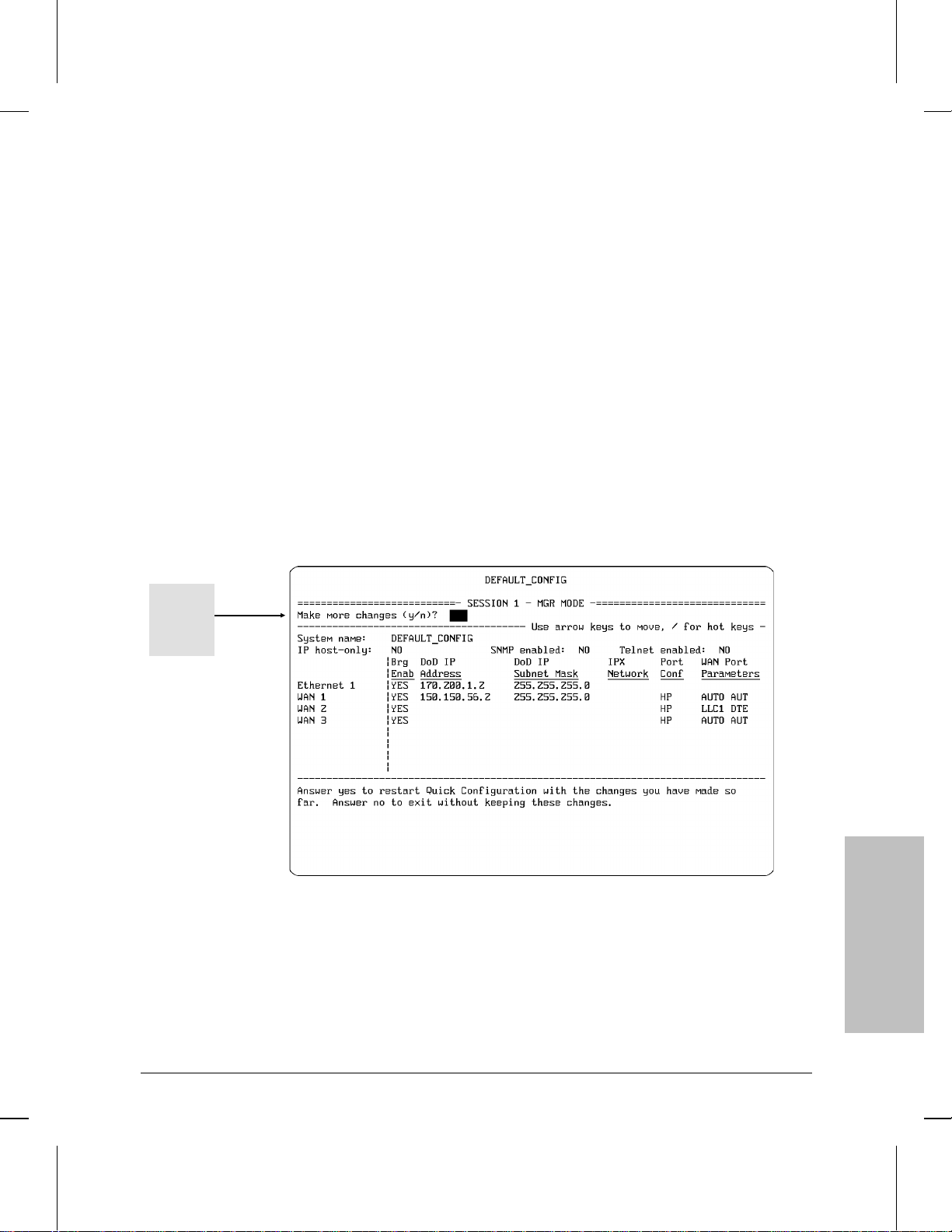
2. Type n and then press [Return]. You will then see the ‘‘make changes’’
prompt:
Figure 3-8.The ‘‘Make Changes’’ Prompt
3. Type n again and press [Return]. The router exits from Quick Configura-
tion and displays the Main menu (page 3-6).
3-11
Page 39

How To Use Quick Configuration
How To Use the ‘‘Hotkeys’’
How To Use the ‘‘Hotkeys’’
The ‘‘hotkeys’’ give you additional configuration editing controls, and are
in two groups:
Display control keys (numeric; 1 through 5)
Configuration Editor1 access keys (alphabetical; Y, N, etc.)
To display the hotkey menu: Type the forward slash (/).
For example, if you start Quick Configuration, display the Quick
Configuration screen and then type /, you will see a set of hotkey
options similar to the following:
Example of
hotkey
options
Figure 3-9. Example of Hotkey Display
Note You can display the hotkey menu from any cursor position in the Quick
Configuration screen except in cases where you have already begun to
type a multiple-keystroke value, such as an IP address or subnet mask.
1
For more information on the Configuration Editor itself, refer to chapter 4, ‘‘How To Use
the Configuration Editor To Create or Change a Configuration’’.
3-12
Page 40

Quick
Configuration
3
How To Use Quick Configuration
How To Use the ‘‘Hotkeys’’
The Numeric Hotkeys
These keys are the same for every cursor position in Quick
Configuration. They let you control display features or exit from Quick
Configuration.
1 Done configuring Typing [1] displays the ‘‘save and exit’’
prompt (page 3-9), allowing you to exit
from Quick Configuration. (Operation is the
same as that for the [Ctrl] [C] key
combination—step 1 on page 3-11.)
2 Display help message When the Help display has previously
been disabled, typing 2 displays the Help
message for the currently highlighted field.
3 Redraw screen Typing 3 redraws the current Quick
Configuration screen.
4 Edit current value Typing 4 lets you change one or more
characters in a parameter value without
having to retype the entire value.
5 Disable help messages
Enable help messages
Typing [5] when Help messaging is enabled
turns off Help messaging for all fields.
Typing 5 when Help messaging is disabled
turns on Help messaging for all fields.
3-13
Page 41
How To Use Quick Configuration
How To Use the ‘‘Hotkeys’’
The Alphabetical Hotkeys
These keys vary, depending on which parameter in the Quick
Configuration screen is currently selected. They either change the
setting of the currently highlighted parameter or take you to the
indicated screen in the Configuration Editor, where you can configure
parameters that are not available in the basic Quick Configuration
screen. In most cases (except for certain X.25 parameters on HP
routers that have the X.25 service), you won’t need these keys unless
you must access parameters that are not displayed in Quick
Configuration.
For example, if you type / while the cursor is on the ‘‘System name’’
field in the Quick Configuration screen, you will see the following
display.
3-14
‘‘E’’ option
Figure 3-10. The Hotkey Menu
Page 42

Quick
Configuration
3
How To Use Quick Configuration
How To Use the ‘‘Hotkeys’’
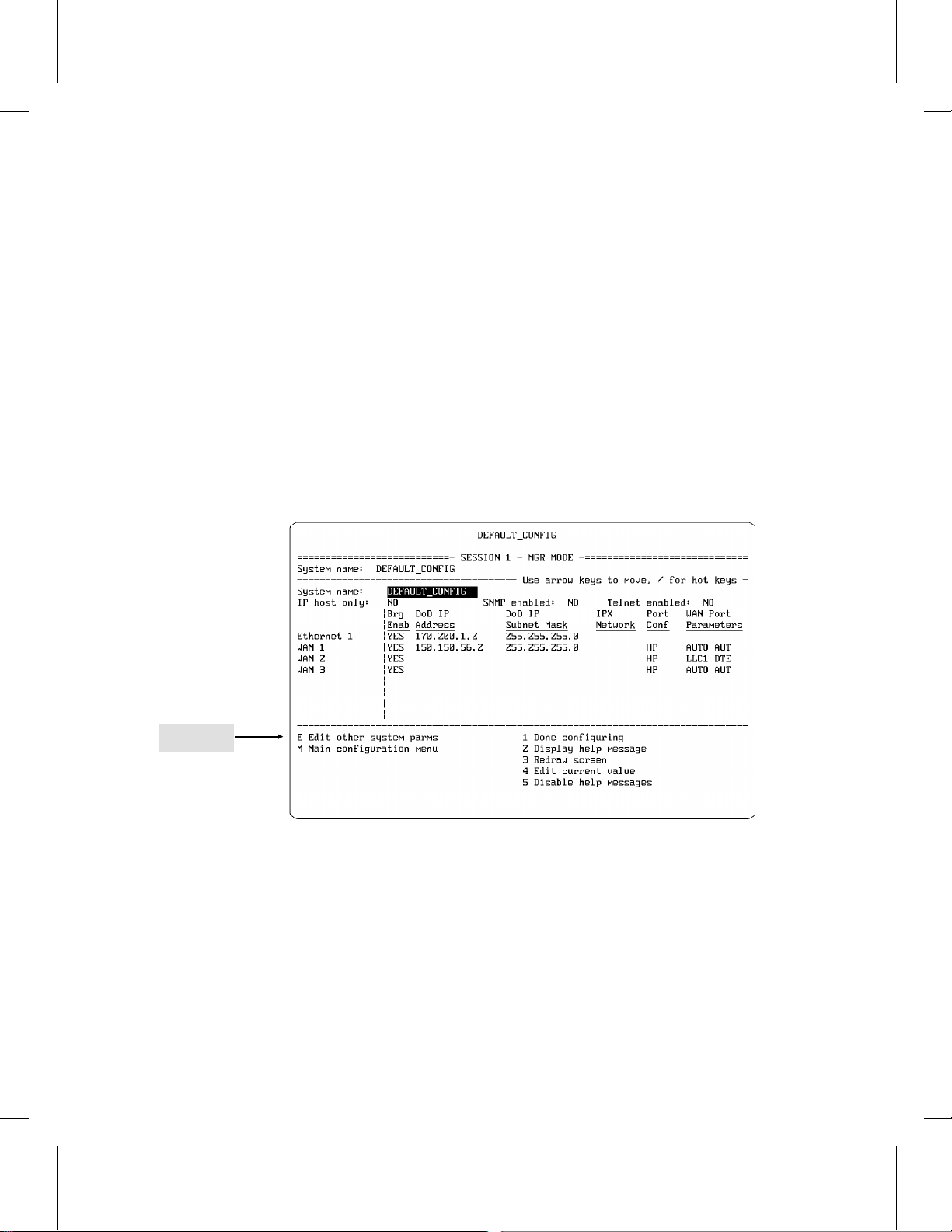
If you then type E (for ‘‘Edit other system parms’’), you will then
see the Configuration Editor screen associated w it h the ‘‘System name’’
parameter:
Figure 3-11. Example of Using ‘‘Edit Other...’’ Hotkey
From this screen you can access any lower-level system parameter
screen in the ‘‘system’’ branch of the Configuration Editor. Similarly,
typing / M in figure 3-10 (for ‘‘Main configuration menu’’) takes
you to the main configuration menu screen (figure 3-3 on page 3-6).
3-15
Page 43

How To Use Quick Configuration
How To Use the ‘‘Hotkeys’’
Figure 3-12. Example of using ‘‘Main...’’ Hotkey
Since the Main Configuration menu is at the ‘‘top’’ of the Configuration
Editor screen hierarchy, you can access any level of any branch of the
Configuration Editor from this screen.
Returning From the Configuration Editor to Quick Configuration.
Pressing [Return] to exit from the screen at which you entered the
Configuration Editor returns you to Quick Configuration. (That is, press
[Return] as many times as is needed to go through all displayed fields,
return to your entry point into the Configuration Editor, and, from there,
to exit.)
For Further Examples. The next section, ‘‘How To Configure for X.25’’,
includes examples of how to use the alphabetical hot keys to access
Configuration Editor screens wit hout exiting from Quick Configuration.
3-16
Page 44

Quick
Configuration
3
How To Use Quick Configuration
How To Configure for X.25
How To Configure for X.25
The X.25 routing service is available on most HP routers. In the factory
default, most of the X.25 parameters are set to default values that may
be acceptable for your application. For a minima l X.25 configuration,
you will need to enter one of the following sets of values:
DDN PDN X.25 Point-to-Point
Default settings are provided
None
for all values needed for
minimal configuration
*You can specify only one PTOP circuit in Quick Configuration. If you want to specify additional circuits,
you must use the Configuration Editor (which you can access from Quick Configuration by using the
[M] Hotkey combination).
X.121 address of the local
port
IP address and X.121 address
of each remote port
X.121 address of the local
X.121 address of the remote
The connection ID for the
(PTOP)*
port
port
remote port
Note: The Configuration Editor provides appropriate default circuit names and
circuit group names.
For descriptions of specific X.25 parameters, refer to the Operator’s
Reference.
[/]
3-17
Page 45

Configured
WAN Port
How To Use Quick Configuration
How To Configure for X.25
To Configure Minimal X.25 service:
1. Configure the desired WAN port in the Quick Configuration screen.
For example, WAN port 1 in the next figure is configured as follows:
• Bridge enabled: Yes
• IP address: 150.150.56.2
• IP subnet mask: 255.255.255.0
(‘‘Port conf’’ and ‘‘WAN Port Parameters’’ are set to their default values.)
3-18
Figure 3-13. Example of Configured WAN Port
Page 46

Circuit Type
Quick
Configuration
3
How To Use Quick Configuration
How To Configure for X.25
2. Type lapb in the ‘‘Port Conf’’ field and press [Return].) The circuit
type then changes to PTOP (Point-to-Point).
Link Type
Figure 3-14. Specify LAPB as the Link Type
3-19
Page 47

How To Use Quick Configuration
How To Configure for X.25
3. Specify the X.25 circuit type—DDN, PDN, or PTOP (the default). (If
you don’t want PTOP, type ddn or pdn for the type of X.25 circuit,
then press [Return].)
• If you specified DDN for the circuit type, no more parameters are
needed for the default configuration. Go to step 4 on page 3-22.
• If you specified PDN, you will need to enter the local DTE
address, the IP address, and the X.121 address, as follows:
Note Use the [Return] key to bypass fields that already contain default values.
– Local DTE address for PDN: Type / l (the [/] and [L]
keys), enter the X.121 address of the local port at ‘‘Local DTE
Address’’, and press [Return] as many times as needed to return
to Quick Configuration. (Refer to figure 3-15 on page 3-21.)
– IP address and X.121 address for PDN: Type / r, enter
the IP address and X.121 address of the remote port, and
press the [Return] key as many times as needed to return to the
Quick Configuration screen. (Refer to figure 3-16 on page
3-21.)
• If you specified PTOP, you will need to enter the local DTE
address, the remote DTE address, and the connection ID, as
follows:
– Local DTE address: Type / l (the [/] and [L] keys), enter
the X.121 address of the local port (at ‘‘Local DTE Address’’),
and press [Return] as many times as needed to return to the
Quick Configuration screen. (Refer to figure 3-17 on page
3-22.)
– Remote DTE address and Connection ID: Type / r,
enter the X.121 address (at ‘‘Remote DTE Addr’’) and the
Connection ID of the remote port, then use [Return] to return to
the Quick Configuration screen. (Refer to figure 3-18 on page
3-22.)
Note If you want to add more connection IDs, type / l instea d of / r. Then
use [Return] to step past Local DTE Address. When you see ‘‘1. X.25
Virtual Circuits’’, type 1 and press [Return], then select the ‘‘Add’’ op-
tion. For more on how to use the Configuration Editor, refer to chapter 4.
3-20
Page 48

Local DTE (X.121) address
Remote X.121
address for
PDN
Quick
Configuration
3
Figure 3-15. Local X.121 Address for PDN
How To Use Quick Configuration
How To Configure for X.25
IP address
Figure 3-16. Remote IP and X.121 Addresses for PDN
3-21
Page 49

How To Use Quick Configuration
How To Configure for X.25
X.121 address for PTOP
Figure 3-17. Local X.121 Address for Point-to-Point
3-22
Remote Connection ID
Remote DTE (X.121) Address
Figure 3-18.Remote X.121 and Connection ID
4. Press the [Ctrl][C] key combination to display the ‘‘save and exit’’
prompt:
Page 50

Quick
Configuration
3
How To Use Quick Configuration
How To Configure for X.25
Save configuration and exit Quick Configuration
(y/n?)
5. Type y and press [Return] to display the ‘‘reboot’’ prompt
Reboot now (y/n?)
6. Type y (for ‘‘yes’’) and press [Return].
While the router is rebooting, the console displays
REBOOTING THE SYSTEM
When you see the message
Waiting for speed sense
the router has finished rebooting. Any configuration changes you
made prior to exiting and rebooting will be implemented in the
router configuration.
7. Press [Return] to return to the Main menu.
To configure additional (non-minimal) X.25 parameters:
As you may have noticed in the procedure to configure for minimal X.25
operation (page 3-18), the ‘‘l’’ and ‘‘r’’ hotkeys give you access to several
parameters other than those needed for minimal X.25 operation. Also,
there are other hot keys that give you access to additional parameters
that you may want to view and change. Thus, af ter you specify X.25
service and the circuit type (DDN, PDN, or PTOP), you can use the
hotkeys to access, view, and change the current settings of all X.25 (or
other) parameters if you find it necessary to do so.
1. Highlight the X.25 circuit type for the desired port. For example:
3-23
Page 51

How To Use Quick Configuration
How To Configure for X.25
X.25 circuit type
Figure 3-19. Highlight the X.25 Circuit Type
3-24
Page 52

Quick
Configuration
3
How To Use Quick Configuration
How To Configure for X.25
2. Type / . You will then see the hotkey menu. For example, with an
X.25 circuit type of PDN, you will see the following menu:
Figure 3-20. Hotkey Assignments
The ‘‘L’’ and ‘‘R’’ options access parameters you need to provide for
minimal X.25 operation (described in the procedure to configure for
minimal X.25 operation—page 3-18). The remaining options (listed
below) give you access to default parameters you can change as
required for non-minimal X.25 (and other) configurations:
• E Edit virtual circuit parms (DDN only)
• X Edit other X.25 parms
• C Edit circuit parms
• M Main configuration menu
3. Type the letter for the option you want. You will then see the corresponding Configuration Editor screen. After you have entered your
changes, press [Return] as many times as necessary to return to the
Quick Configuration screen.
4. Press the [Ctrl] [C] key combination to display the ‘ ‘save and exit’’
prompt:
Save configuration and exit Quick Configuration
(y/n?)
3-25
Page 53

How To Use Quick Configuration
How To Configure for X.25
5. Type y and press [Return] to display the ‘‘Reboot now (y/n)?’’ prompt
Reboot now (y/n?)
6. Type y (for ‘‘yes’’) and press [Return].
While the router is rebooting, the console displays
REBOOTING THE SYSTEM
When you see the message
Waiting for speed sense
the router has finished rebooting. Any configuration changes you
made prior to exiting and rebooting will be implemented in the
router configuration.
7. Press [Return] twice to return to the Main menu.
3-26
Page 54

Quick
Configuration
3
How To Use Quick Configuration
Operating Notes
Operating Notes
Parameter List
Quick Configuration is set to the following default parameter values at
the factory and whenever you use the Reset/Clear button combination to
clear the router. (For more on clearing the router, refer to the
installation guide.)
Parameter Default
System name
IP host-only
SNMP enabled
TELNET enabled
Brg Enab
DoD IP Address
DoD IP Subnet Mask
IPX Network
Port Conf
Ring interface (token ring)
Link type (WAN)
Bridge type (FDDI)
WAN Port Parameters
Quality of service (WAN)
Point-to-Point address
(WAN)
AppleTalk Net Range
AppleTalk Zone Name
DECnet area.node
Note that when you start the Quick Configuration utility, the cursor is
always set to the ‘‘System name’’ field. (The default system name is
DEFAULT_CONFIG.) Also, the Help messages are active unless you
have previously used the / 5 hotkey combination to turn them off.
DEFAULT_CONFIG
NO (leaves router in router/host mode)
NO
NO
YES (enables bridging on indicated port)
—
—
— (IPX network number)
16
HP (Hewlett-Packard)
TR (Translating)
AUTO
AUTO
—
—
—
3-27
Page 55

How To Use Quick Configuration
Operating Notes
Data Entry
When you move the cursor from one field to another, the data entry field
changes to prompt you for the new data. When you type the new data, it
appears in the data entry field, but does not appear in the corresponding
field until you press [Return].
Saving vs. Saving and Rebooting
‘‘Saving’’ a new configuration holds that configuration in memory and
displays the new settings in the Quick Configuration display (and in the
Configuration Editor displays). However, because the router always
uses the configuration with which it was last booted, the new
configuration does not replace the previous configuration until you
reboot the router. Thus:
1. If you save a configuration (by typing y at the ‘‘save and exit’’
prompt—page 3-9). . .
3-28
2. . . . but then choose not to reboot the router (by typing n at the
‘‘Reboot now (y/n)?’’ prompt—page 3-10)
Then the configuration changes are saved in memory, but are not
implemented in the current configuration, unless you subsequently
reboot the router in one of the following ways:
Re-enter the Quick Configuration utility, then exit as described under
‘‘To exit from the Quick Configuration utility and reboot the router’’
on page 3-9.
Use the Network Control Language Interpreter (NCL) Boot
command.
Press the Reset button on the back of the router.
Cycle the power.
Page 56

Quick
Configuration
3
How To Use Quick Configuration
Operating Notes
When To Use the Configuration Editor
Hewlett-Packard recommends that in most configuring situations you
use Quick Configuration first. Then, if necessary, use the Configuration
Editor to enter any additional configuration changes needed to optimize
the router for more efficient operation or to customize it for complex
routing situations. For example, you will need to use th e Con figuration
Editor for parameters in the following areas:
OSPF
V.25 bis
XNS
filters
static routes
adjacent hosts
timers
the internal clock (for WANs)
You can enter the Configuration Editor from the Main menu (page 3-6).
But if you are already in Quick Configuration, you can save time by
using the / m hotkey combination to enter the Configuration Editor, then
reboot as you exit from Quick Configuration.
Interacting with the Configuration Editor. The Quick Configuration
utility is a fast way to access a small subset of the complete parameter
set you can access by using the Configuration Editor. Thus, you can use
the Quick Configuration utility any time you want to add to or change
the parameter settings it covers. (To simply display the contents of
Quick Configuration, you can use the NCL Summary command —page
7-9.) When you change parameter values in Quick Configuration and
then reboot the router, these changes overwrite any earlier configuring
of the same values by the Configuration Editor. Similarly, when you
change parameter values in the Configuration Editor that affect the
parameter set accessed by Quick Configuration, and then reboot the
router, these changes will overwrite any earlier configuring of the same
values by Quick Configuration.
3-29
Page 57

How To Use Quick Configuration
Operating Notes
Troubleshooting a Quick Configuration
If the router fails to operate in your network after you have used the
Quick Configuration utility, there are several areas to investigate for the
source of the problem:
Check the Quick Configuration display for errors or omissions in the
data that you provided.
Ensure that your network design allows for any Quick Configuratio n
default settings that may remain after you entered your parameter
values.
Ensure that you save the configuration and then reboot (page 3-9).
Ensure that all cable connections are firm and are routed properly.
Check the LEDs on all connected routers to ensure that all ports are
operating properly.
Use the NCL Ping command to send an ICMP echo request message
to each IP address connected to your router. (Refer to the ‘‘NCL
Command Summary’’ on page 7-7 or to the Operator’s Reference.)
Determine whether there is any need for additional configuring, as
indicated by unique or advanced configuration features used in the
network(s) to which your router is connected . (Refer to ‘‘When To
Use the Configuration Editor’’ on page 3-29.)
Check the event log to ensure that configured services (such as IP)
have started and are running properly. (Refer to the operator’s guide
for your router.)
Check the statistics screens you can access from the Main menu for
signs of impeded or failing operation.
Check your current configuration against the configurations of
adjacent routers to detect any settings that require reciprocal values
(such as DTE and DCE for WAN ports). Also check for any simple
configuration errors such as duplicate or incorrect IP addresses, or
incorrect subnet masks. (Create a list of interdependent values in the
other router(s) that dictate related or reciprocal set tings in your
router.)
The installation and operator’s guides for your router provide additional
help for investigating and analyzing router operation and failures.
3-30
Page 58

Quick
Configuration
3
How To Use Quick Configuration
Operating Notes
The HP Router 650: How To Update the
Interface Module Configuration After
Removing or Replacing a Module
Interface modules in an HP 650 router can be inserted, removed, or
replaced while the router is operating. However, when one of these
actions results in either no replacement for a removed module or
replacement with a module having a different set of ports, then the
software configuration will not match the current hardware
configuration. This subsection describes how Quick Configuration
operates in these conditions and how to use Quick Configuration to
update the interface module configuration after removing or replacing a
module.
Note Quick Configuration reacts to a change in interface modules only when
the change takes place before you start Quick Configuration. That is, if a
module change occurs while Quick Configuration is in use, the effects of
the change will not appear in Quick Configuration until yo u exit from
Quick Configuration and then restart it.
Rebooting the router causes the router to re-initialize itself by using the
most recently saved configuration. Thus, after removing or replacing a
interface module, rebooting the router does not update the interface
module configuration unless you have also used Quick Configuration (or
the Configuration Editor) to update and save the router’s configuration.
3-31
Page 59

How To Use Quick Configuration
Operating Notes
Removing a Previously Configured Interface Module
Removing a previously configured interface module and subsequently
starting Quick Configuration results in a modified display that indicates
which port configurations are no longer valid. For example, the
following screen illustrates an HP Router 650 with one WAN interface
module and one Ethernet interface module installed and configured as
shown:
Installed Interface Module Configuration
Four-Port Synchronous WAN Module WAN ports 1 and 2 configured
Four-Port Ethernet Module Ethernet ports 1 and 2 configured
3-32
Figure 3-21. Two Interface Modules Installed and Configured
Page 60

Highlighted port labels
Quick
Configuration
3
indicate previously
configured ports on a
interface module that
has been removed
from the router
How To Use Quick Configuration
Operating Notes
If the Ethernet interface module is removed and Quick Configuration is
subsequently restarted, the labels for the ports on the removed module
will be highlighted to indicate that they are still configured in the router,
even though they are no longer installed.
Figure 3-22. Identifying Nonexistent Ports in the HP Router 650 Configuration
You can then do one of the following:
Delete the non-existent ports from the configuration. This is the
recommended action if you will not be installing another interface
module in the same slot as the module you just removed. (Refer to
‘‘To use Quick Configuration to delete the non-existent ports from
the configuration’’ on the next page.)
Edit the configuration (including the parameters for the removed
interface module), then reboot the router. You would do this if you
wanted to install a new interface module in the slot from which have
just removed the original interface module. To edit the configuration,
refer to the earlier sections of this chapter.
3-33
Page 61

How To Use Quick Configuration
Operating Notes
To Use Quick Configuration To Delete the Non-Existent Ports
from the Configuration:
1. Move the cursor to any row occupied by one of these ports. The Help
window will then display the messages indicated below:
Cursor positioned in any configured row for
which the interface module has been removed
Help message indicating
port configurations for
which there is no hardware
present
3-34
Figure 3-23. Removed Ports for which a Configuration Exists
2. Press the [Ctrl] [D] key combination to delete the configuration for the
nonexistent interface module. You will then be prompted with the
message
Are you sure you want to delete the old configurations for this empty slot?
3. Type y and press [Return] to delete the configuration for the empty slot.
Notice that the highlighted port labels for th e deleted ports will remain
in the Quick Configuration screen until you save the new configuration
and exit from the Quick Configuration u t ility (described in the following
steps).
Page 62

Quick
Configuration
3
How To Use Quick Configuration
4. Reboot the router by doing the following:
5. Press the [Ctrl] [C] key combination.
6. When you see the ‘‘save and exit’’ prompt:
Save configuration and exit Quick Configuration
(y/n)?
7. type y and press [Return].
8. When you see the reboot prompt:
Reboot now (y/n)?
9. Type y again and press [Return] to reboot the router.
10. While the router is rebooting, the console displays
REBOOTING THE SYSTEM
11. When you see the message
Operating Notes
Waiting for speed sense
12. the router has finished rebooting. Any configuration changes you
made prior to exiting and rebooting will be iimplemented in the
router configuration.
3-35
Page 63

How To Use Quick Configuration
Operating Notes
Replacing One Type of Interface Module with Another Type
Replacing a previously configured interface module with another
module having a different set of ports, and subsequently starting Quick
Configuration results in a ‘‘Configuration Conflict Alert’’. For example,
the following screen illustrates an HP Router 650 with one configured
WAN interface module.
3-36
Figure 3-24. One WAN Interface Module Installed and Configured
Moving the WAN interface module indicated above to slot 4 and
installing an Ethernet interface module in its place (slot 2) creates a
configuration conflict. If Quick Configuration is subsequently started, a
warning screen similar to the one shown in figure 3-25 appears.
Page 64

Figure 3-25. The "Configuration Conflict" Screen
Quick
Configuration
3
How To Use Quick Configuration
Operating Notes
Indicates slot(s) in which a
configuration conflict exists
1. In the above case:
a. If you don’t want to continue in Quick Configuration, type n and
press [Return] to return to the Main Menu.
Note If you type n and return to the Main menu, the configuration conflict
remains in the router and the above screen will re-appear the next time
you start Quick Configuration.
b. If you want to eliminate the conflict and continue with Quick
Configuration, type y and press [Return].
You will then see the following prompt:
Are you sure you want to delete all conflicting
configurations (y/n)?
2. Type y and press [Return] again to confirm conflict deletion and to start
Quick Configuration.
3-37
Page 65

How To Use Quick Configuration
Operating Notes
3. Continuing from the above example, the Quick Configuration screen
would show the WAN interface module moved to slot 4 and the
Ethernet interface module installed in slot 2.
Figure 3-26. Quick Configuration Showing Unconfigured Interface Modules
Neither module is configured because:
– The WAN interface module configuration that was in slot 2
was in conflict with the Ethernet interface module and was
therefore deleted (step 1b), leaving slot 2 without any interface module configuration.
– Slot 4 had no interface module configuration, and was there-
fore unaffected by moving the WAN interface module to that
slot.
4. In this example, to resume routing operations, it is necessary to
configure one or more ports on either module and reboot the router.
3-38
Page 66

4
How To Use the Configuration
Editor To Create or Change a
Configuration
Page 67

How To Use the Configuration Editor
Introducing the Configuration Editor
Introducing the Configuration
Editor
The Configuration Editor accesses a hierarchy of menus and screens
that include any parameters you need for customizing the router beyond
the ‘‘getting started’’, or factory default level. Using this edit or, you can
customize all parameters needed to integrate the router into your
system (including the subset of parameters you can access through
Quick Configuration).
Generally, when you first create a configuration, it is easiest to begin by
using Quick Configuration to establish a minimal version of the
configuration to use in establishing functioning network connections.
However, when you are ready to use parameters that are not available in
the Quick Configuration screen, it is time to move on to the
Configuration Editor. You can do so either by starting the Configuration
Editor from the Main Menu or starting it from within Quick
Configuration by using the hotkeys. (Refer to ‘‘How To Use the Hotkeys’’
on page 3-12.)
4-2
You can use the Configuration Editor to create a configuration in a
router through either a directly connected terminal or a terminal
connected to the router via Telnet. (For information on Telnet, refer to
‘‘Telnet: How To Establish a Virtual Terminal Connection to a Remote
Node’’ on page 7-10.) You can also move an existing configuration
between routers or between a router and a host on the network. (Refer
to ‘‘Using TFTP To Transfer Operating Code, Configuration, and NCL
Display’’ on page 7-30, and ‘‘Using PC Modem Access T o Transfer
Configuration and NCL Display on page 7–32.)
Page 68

4
How To Use the Configuration Editor
The Configuration Editor Process
The Configuration Editor Process
The configuration process consists of four major steps, described below.
Step 1: Define Global and Session Parameters Global parameters specify which routing service applications are enabled on your
router, and also define local and remote session modes. The specific
session parameters specify the interface between the router and various
I/O devices—console, modem, and Telnet—for the session modes. The
‘‘System’’ and ‘‘Software’’ items access these parameters.
Step 2: Establish Communication Channels Communication
channels define both the physical and logical connections between the
router and various network devices. The ‘‘Lines’’ item accesses the
physical connection parameters for each router interface (port). The
‘‘Circuits’’, ‘‘Circuit Groups’’, and ‘‘V.25 bis Network Mapping’’ items
access circuit-related parameters for individual ports. The circuit and
circuit group parameters are regularly used in all routing configurations.
V.25 bis network mapping is used only when V.25 bis circuits form part
of a network.
Configuration
Editor
Step 3: Customize Protocol Application Modules The protocols
require network-specific data in order to provide bridging, routing,
and/or network-management services. The remaining items in the
Configuration Menu access these paramete rs. You need to use only
those items that correspond to the routing service modules you enable
in step 1, above (under the ‘‘Software’’ item).
Step 4: Implement the Configuration After you customize the
protocol applications, complete the configuration process by (1) saving
the configuration and then (2) implementing it by rebooting the router.
For further configuration information, refer to:
For tutorial information on the use and operation of the various
routing services, refer to HP Routing Services and Applications
For descriptions of the individual parameters used in the
Configuration Edito r, refer to the Operator’s Reference.
For a guide to finding parameters in the Configuration Editor, refer to
the ‘‘Parameter Locator’’ in the appendix to the Operator’s Reference.
4-3
Page 69

To enter from the
Main Menu, type 3
How To Use the Configuration Editor
How To Enter the Configuration Editor
How To Enter the Configuration
Editor
4-4
Figure 4-1. The Main Menu
You can enter the Configuration Editor from either the Main Menu or
from the Quick Configuration screen.
To enter from the Main menu, just type 3, which is the list number
for the Configuration Editor.
To enter from the Quick Configuration screen (described in chapter
3), type / m. (For more information on using the Configuration
Editor while in Quick Configuration, refer to ‘‘How To Use the
Hotkeys’’ on page 3-12.)
Page 70

4
How To Use the Configuration Editor
How To Enter the Configuration Editor
When you start the Configuration Editor, the configuration menu
appears:
Note The actual configuration menu displayed on your console reflects the
configuration features available in your router. This manual uses examples depicting the full feature set, which is available in most HP routers.
For a listing of the features available in your router, refer to the release
notes you received with the router or with your most recent software
update.
Configuration
Editor
Figure 4-2. The Configuration Menu
4-5
Page 71

How To Use the Configuration Editor
How To Exit From the Configuration Menu
How To Exit From the
Configuration Menu
If you enter the Configuration Editor from the Main menu, do
the following to exit:
1. Press [Return] as many times as you need to return to the Configuration
menu (figure 4-2).
2. Press [Return] once again to display
Back to menu ?
3. Then do one of the following:
• If you want to exit from the Configuration Editor without saving
any changes you made, press [<] to display
Exit without saving ?
Then press [Return] again to exit from the Configuration Editor
without saving any changes you made.
• If you want to exit from the Configuration Editor and save any
changes you made, press [>] twice to display
Save and exit ?
Then press [Return] again to exit and save any changes you made.
Note ‘‘Saving’’ a new configuration retains it in memory, but does not delete
the ‘‘old’’ configuration nor re-initialize the router with the new configuration. To re-initialize the router with a new configuration that you have
just saved, reboot the router (or turn the power off, then on again). To
reboot the router, use the boot command (page 7-8 in this manual; refer
also to the description of the boot command in the Operator’s
Reference’’.
4-6
Page 72

4
How To Use the Configuration Editor
How To Exit From the Configuration Menu
If you enter the Configuration Editor from Quick Configuration,
do one of the following to exit:
To exit and reboot the router, refer to ‘‘How to exit from Quick
Configuration and reboot the router’’ on page 3-9.
To exit without rebooting, refer to ‘‘How to exit from Quick
Configuration without saving changes’’ on page 3-11.
Configuration
Editor
4-7
Page 73

How To Use the Configuration Editor
How To Operate the Configuration Editor
How To Operate the Configuration
Editor
In the Main menu (figure 1-1 on page 1-6), type 3 to s elect the
Configuration Editor and display the Configuration Menu.
Note Most HP routers have all of the configuration features described in this
chapter. However, some features are not available in certain basic router
models. To determine the feature set in your router, refer to the release
notes you received with the router or with your latest software update.
Access to global
and session
parameters
Access to protocol
selection
Access to
communication
channels
Access to
application and
network
management
modules
Selection prompt
Figure 4-3. Example of the Configuration Menu
4-8
Page 74

Configuration Categories
4
How To Use the Configuration Editor
How To Operate the Configuration Editor
The configuration categories include the available routin g ap plications
and some general items. The number in parentheses to the right of each
item indicates the number of entries currently configured in the
category. A 0 (zero) indicates that nothing is configured for that
category. For example, in the preceding screen, item 7 is not configured:
7. DoD Internet Router (0)
Note In figure 4-3, the DEFAULT_CONFIG label appears when you have not
yet assigned another name to the router. HP recommends that you
assign a more specific name to this router later in the configuration
process. When you do, that name appears instead of DEFAULT_CONFIG.
Each item listed in figure 4-3 is briefly described below. F or information
on the parameters accessed by these items, refer to the Operator’s
Reference.
1. System Names the router, specifies how the router initializes
software services during a power-up or boot situation, and assigns
values to global and session parameters.
2. Software Loads the application software supplied with your
router.
Configuration
Editor
3. Lines Specifies the physical connections between the router and
the LANs and/or long-haul transmission facilities with which the router
interfaces.
4. Circuits Specifies the logical connections between the router and
the LANs and/or long-haul transmission facilities with which the router
interfaces.
5. Circuit Groups Balances traffic across circuits.
6. Bridge Configures the Bridge application to your specific
requirements.
4-9
Page 75

How To Use the Configuration Editor
How To Operate the Configuration Editor
The remaining items (including some that are not available on all
models) provide tools for adjusting application or network management
software modules to your requirements. Access only the items
corresponding to the application or network management software
modules you want to enable.
7. DoD Internet Router
8. DECNET IV Routing Service
9. SNMP Sessions
10. Xerox Routing Service
11. IPX Routing Service
12. AppleTalk Router
13. X.25 Network Service
14. V.25 bis Network Mapping
Moving From One Screen to Another
At the bottom of the Configuration Menu screen (figure 4-3) and many
other screens is the prompt:
Enter selection (0 for previous menu): _____
Whenever this prompt occurs, it is preceeded by a numbered list of
items you can select. If you don’t want to access any of the listed items,
just press [Enter] to return to the preceding screen or action item. But if
you want to access one of the listed items, type the number for that item
and press [Enter]. Then:
If the item you select contains no en tries (indicated by ‘‘ (0)’’ at the
end of the item) such as:
DoD Internet Router (0)
you will be prompted by the message
Do you wish to add ...? Yes
4-10
Page 76

4
4
How To Use the Configuration Editor
How To Operate the Configuration Editor
Press [Return] to select the Yes option. The parameters you want to
add will then appear. Follow the prompts to enter the values for the
desired parameters.
For example, with the configuration menu displayed, if the DoD
Internet Router (IP) Service was not configured and you wanted to
access it, you would type 7 and press [Return] to display the following:
IP service (0 indicates ‘‘not configured’’)
Prompt to access IP configuration
n
o
f
C
Configuration
iguration
Editor
Editor
Figure 4-4. Example of Accessing an Item That Is Not Currently Configured
Continuing from page 4-10, if the item you select contains one or
more entries (indicated by a ‘‘(1)’’, ‘‘(2)’’, or other number at the
end of the item) such as:
Circuits (2)
the entries will appear as a numbered list and you will be prompted
with
Action (->> for selections) : Previous Display
For example, with the configuration menu displayed, if one Ethernet
port and one WAN port were configured and you wanted to add
another port configuration, you would type 4 and press [Return] to see
a screen similar to the following:
4-11
Page 77
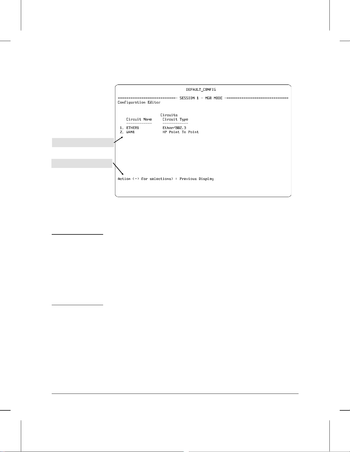
List of configured circuits
Prompt for your next action
How To Use the Configuration Editor
How To Operate the Configuration Editor
Figure 4-5. Example of Access to Previously Configured Elements
Note The examples of default circuit names in figure 4-5, above, appear in HP
Series 200 and 400 routers. Default circuit names in HP Series 600 routers include the slot number in which the port is installed. For example, if
a four-p ort Ethernet interface module is installed in slot 2 of the HP
Router 650, the circuit name of the first port on that module would be
ETHER21. Similarly, if a WAN module was installed in slot 3, then the
circuit name of the first port on that module would be WAN31. To help
simplify circuit configurations on an HP Router 650, it is recommended
that you use this method for identi fyin g t h e sl ot and port locations for all
circuits.
4-12
Page 78

4
How To Use the Configuration Editor
How To Operate the Configuration Editor
You then have five actions from which to choose:
• Previous Screen: To back up to the previous screen, choose
Previous Display by simply pressing [Return].
• Delete: To delete an entry, use [<] to choose Delete, then press
[Return]. If you are then prompted for the number of a listed entry,
type the number of the entry to delete and press [Return] again.
When you are prompted with
You are sure you want to delete ? No
use [<] to select Yes, then press [Return].
• Add: To add an entry, use [<] to choose Add. Then press [Return]
and follow the prompts to enter the desired parameter values.
Modify: To modify the configuration for an entry, use [<] to choose
Modify, then press [Return]. If you are then prompted for the number
of a listed entry , type the number of the entry to delete and press [Return]
again. Then follow the prompts to modify the desired parameters.
Browse: To view the current settings for an entry without changing
them, use [<] to choose Browse. If you are then prompted for the
number of a listed entry, type the number of the entry to delete and
press [Return] again.
Configuration
Editor
4-13
Page 79

How To Use the Configuration Editor
How To Operate the Configuration Editor
Entering or Changing Parameter Values in
Configuration Screens
Throughout the configuration screens, there are ‘‘type-in’’ and ‘‘select an
option’’ parameter data fields. For example:
Circuit Name : ETHER1______
This is a ‘‘type-in’’ field in which you provide a value. Type-In fields
are always underlined. Fill in a blank underlined field or type over
the existing entry. Any underlines you see at the end of existing text
indicate how long the entry may be. To correct a mistake, use the
backspace key (not the [Delete] key) to reposition the cursor, and then
retype. When you finish typing an entry , press [Return] to terminate it
and move on to the next field or option. Notice that if yo u a re typ in g
over one entry with another, shorter entry, you should not try to
delete the extra characters; just press [Return] after typing the last valid
character in the string. Any characters remaining from the old string
will be truncated. For example, if you were to replace an internet
address of 100.100.100.10 in the IP Network Interface Definitions
screen with another address of 10.10.10.1, you would just type the
second address over the first and press [Enter]. (The remaining ‘‘0.10’’
from the first address would be truncated when you pressed [Enter].)
Original Address String: 100.100.100.10_
After New Entry Typed: 10.10.10.10.10_ (‘‘0.10’’ is excess)
After You Press [Return]: 10.10.10.1 ([Return] truncates the excess)
4-14
Cursor position after new entry
Auto Enable : Yes
This is a ‘‘Select an Option’’ field, which always displays a current
setting that is one of a number of preprogrammed options. Use the
[>] or [<] key to move through the supplied options. When the option
you choose is displayed, press [Return] to enter it. This also moves the
cursor to the next menu, screen, or prompt.
Page 80

4
How To Use the Configuration Editor
How To Operate the Configuration Editor
To exit from the Configuration Editor, return to the Configuration Menu
screen (figure 4-3). At the Enter selection prompt, press
[Return]. At the option
Back To Menu ?
use the [>] or [<] key to select either Save and Exit ? (if you want to
save any changes you have made) or Exit without Saving ? (if
you don’t want to save any changes you have made) Pressing [Return] for
either one then returns you to the Main menu.
To implement the changes you make in a Configuration Editor ses-
sion, do the following:
a. Choose Save and Exit.
b. Boot the router (by using the NCL Boot command--refer to page
7-8).
To abandon the changes made in this Configuration Editor session
and keep the previous configuration, choose
Configuration
Editor
Exit without Saving
and press [Return].
4-15
Page 81

Page 82

5
How To Use the Event Log T o
Analyze Router Operation
Page 83

How To Use the Event Log
Introducing the Event Log
Introducing the Event Log
This chapter describes the event messages generated by the router and
stored in the event log, how to access the event log from the Main menu,
and how to navigate through the log.
The event log is a first-in, first-out buffer in RAM. (See figure 5-1 for
some sample entries.) Each entry is a line composed of five fields:
severity is one of the following codes:
D (debug) indicates installation and diagnos t ic information.
I (information) indicates routine events.
W (warning) indicates that a service has behaved unexpectedly.
P (performance) indicates that a current service has degraded or
upgraded.
M (major) indicates a service appearance/disappearance.
date is the date, in mm/dd/yy format, that the entry was placed
in the log.
time is the time, in hh:mm:ss format, that the entry was placed in
the log.
object is the system variable (such as ‘‘cct.’’ for ‘‘circuit event
messages’’) that generated the log entry.
event message (within quotes) is the event message.
For information about the event messages you find in your router’s
event log, refer to the Operator’s Reference. Each listed message is
accompanied by an explanation and a recommended action (if any is
required and/or available). The messages are grouped by the system
variables (objects) that generate them and are listed alphabetically.
More information about variables and their structure in th e management
information base is also included in the HP Routing Services and
Applications.
5-2
Page 84

5
How To Use the Event Log
Entering and Navigating in the Event Log Display
Entering and Navigating in the
Event Log Display
You can enter the event log in either of the following two ways:
In the Main menu (figure 1-1 on page 1-6), press [4] to display the
Event Log.
In the NCL interpreter, execute the Logi command.
Event Log
Figure 5-1. Example of an Event Log Display
Note Event log messages in the HP Series 600 routers include, where appropri-
ate, the slot number associated with the source of a displayed event.
Event log messages in HP Series 200 and 400 routers do not use slot
numbers. For example:
S 600:
S 200/400:
I 07/04/94 16:17:44 mgr.auto_enable: ‘auto-enabling ’cct.WAN21’‘
I 07/04/94 16:17:44 mgr.auto_enable: ‘auto-enabling ’cct.WAN1’‘
When you first display the event log, the first event of the most recent
reboot is positioned at the top of the display. (See the first two lines of
5-3
Page 85

How To Use the Event Log
Entering and Navigating in the Event Log Display
the event display in figure 5-1.) To display other portions of the log
—preceding or following the currently visible portion—use the keys
described in the following table.
Event Log Control Keys
Key Action
[Return] or
[N] or
Advance display by one page
(next page)
[SPACE]
[P] Roll back display by one page (previous page)
[v] or
[D]
[^] or
[U]
[>] or
[B] or
[E]
Advance display by one event
(down a line)
Roll back display by one event
(up a line)
Display last, newest page
(bottom of log)
(end of log)
[T] Display the first, oldest page (top of log)
[C] Display the first page for current boot
[?] or
Display help for event log
[Shift]-[?] or
[H]
[<] or
[Q] or
Exit from event log back to Main menu
(quit)
[X]
5-4
This first event displayed at entry is not necessarily the first event in the
log. The log may contain entries that occurred prior to the most recent
reboot.
The event log holds up to 1,000 lines in chronological orde r, from the
oldest to the newest. Each line consists of one complete event message.
Once the log has received 1000 entries, it discards the current oldest line
Page 86

5
How To Use the Event Log
Entering and Navigating in the Event Log Display
each time a new line is received. The event log window contains 20 lines
and can be positioned to any locatio n in the log.
Log status line
Range of log events displayed
Figure 5-2. The Event Log Status Line
Current
event log
contents
Line 1184
(current beginning of log)
Figure 5-3.The Event Log Display Window
The log status line at the bottom of the display identifies where in the
sequence of event messages the display is currently positioned. Figures
5-2 and 5-3 show an event log window, a log status line, and the location
of the window within the complete event log. In this example, events
1881-1900 are displayed and there are 1000 events currently in the log.
Event Log Window
Line 1881
Line 1900
Event Log
Range of events in the log
Line 2183
(current end of log)
5-5
Page 87

How To Use the Event Log
Entering and Navigating in the Event Log Display
The line numbers appearing in the status line continue consecutively.
However, as indicat ed earlier, the log never contains more than 1,000
consecutive lines. For example, if the status line reads
Log events on screen 3378–3397,in memory 2845–3844. Press ’?’ for help.”
then there are 1,000 lines in the log (it is full) and line 3378 (the 534th
line in the current log contents) is at the top of the display.
The router maintains the event log in a reserved area of memory that is
not affected by software reboots. This means that any reboot under
software control (the Boot command, TFTP updates, and ‘‘fatal
exceptions’’) preserves previous log entries. New entries are simply
appended to the existing list and old entries over the 1,000-line limit are
dropped.
However, the event log will be erased if either of the following occurs:
The router is cleared or reset using the Clear and/or Reset buttons.
A fatal exception occurs while the Automatic Reboot parameter is
set to No.
Power to the router is interrupted.
Note
If a fatal exception occurs, the even t log will be maintained only if the
Automatic Reboot parameter in the Global Parameters screen is set to
Yes (the default). (If this parameter is set to ‘‘No’’, then it is necessary to
reboot the router by using the Reset button, which clears the event log.
To locate Automatic Reboot in the parameter hierarchy, refer to the
‘‘Pa ram et er Locator’’ in the appendix to the Operator’s Reference. To
learn more about Automatic Reboot, refer also to the Operator’s
Reference.
Note When the router goes down under software control, it enters this event
and the reason for it in the event log. It repeats this entry when the
router reboots, giving you information about the event in cases where
the existing log is lost after the router goes down. This happens in
instances where the router was cleared or reset as described above after
going down under software cont rol.
5-6
Page 88

6
How To Use the Statistics Screens T o
Analyze Router Operation
Page 89
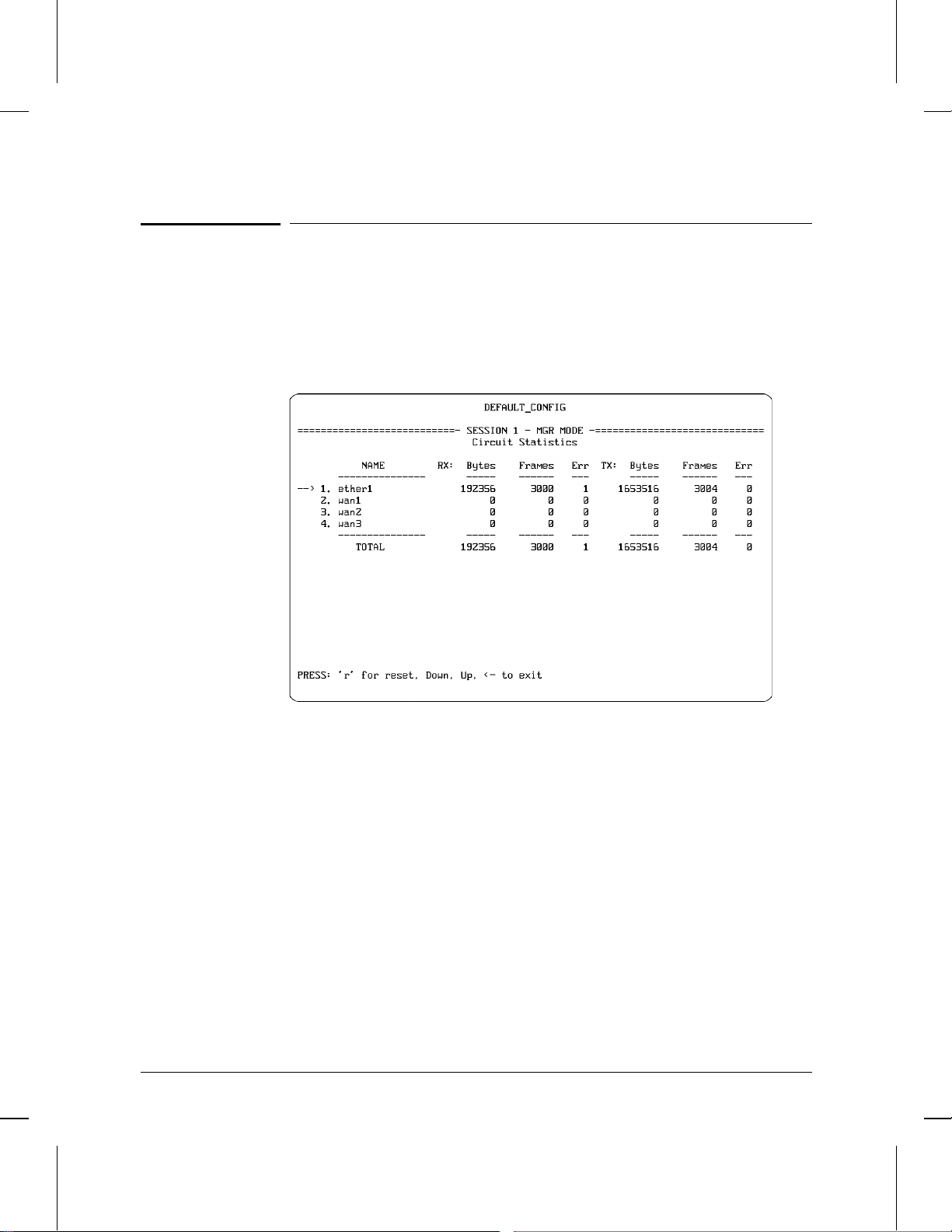
How To Use the Statistics Screens To Analyze Router Operation
Introducing the Statistics Screens
Introducing the Statistics Screens
This chapter describes how to use the statistics recorded by the router
during network operation. It tells you how to access the Statistics
Screens menu, how to display specific statistics screens on the console,
and how to interpret statistical displays.
6-2
Figure 6-1. Example of a Statistics Screen
Page 90

Statistics
Screens
6
How To Use the Statistics Screens To Analyze Router Operation
Introducing the Statistics Screens
The functions of the statistics screens are to provide the following:
Circuits Statistics: Provide summary data for each individual circuit,
including how many bytes and frames were received and transmitted
and how many frames contained errors.
Per Second Statistics: Provide summary data on traffic vol ume for a
per-second basis for each circuit on the router.
Bridge Statistics: Provide summary data for each bridging circuit
group, including how many frames received, forwarded, flooded, and
dropped.
DECnet Router Statistics: Provide summary data for each IP router
network interface, including how many frames received, forwarded,
and dropped.
DoD IP Router Statistics: Provide summary data for each IP router
network interface, including how many datagrams received,
forwarded, handled within the router, and dropped.
XNS Router Statistics: Provide summary data for each XNS network
interface, including how many datagrams received, forwarded,
handled within the router, and dropped.
IPX Router Statistics: Provide summary data for each IPX network
interface, including how many datagrams received, forwarded,
handled within the router, and dropped.
AppleTalk Router Statistics: Provide summary data for each Apple-
Talk router circuit group, including how many packets received,
forwarded, and dropped.
Buffers Usage Statistics: Provide information on buffer allocation
and use.
For an example of each statistics screen type, along with a description
of each statistics data category, refer to the Operator’s Reference.
6-3
Page 91

How To Use the Statistics Screens To Analyze Router Operation
How To Access the Statistics Screen Menu
How To Access the Statistics
Screen Menu
With the Main menu (figure 1-1) displayed, press [1] to display the
Statistics Screen menu.
Note The actual Statistics Screen menu displayed on your console reflects the
lines, circuits, and routing services you have already configured. You
may have fewer than the example shown below. The Circuits, Per
Second, and Buffers Usage Statistics items are always listed.
6-4
Figure 6-2. Example of the Statistics Screen Menu
Page 92

Statistics
Screens
6
How To Use the Statistics Screens To Analyze Router Operation
How To Access the Statistics Screen Menu
At the bottom of the Statistics Screens menu screen is the prompt:
PRESS: ? for help, Down, Up, <- to exit, <RETURN> to select
You can choose from:
To display help text for any statistics screen: Use [v] or [^] to posi-
tion the pointer to the menu item about which you want help. Then
use the [Shift] [?] key combination to display the help. To return to the
Statistics Screen menu, press [<]. For example, to display help for the
buffers usage statistics item in figure 6-3, below, you would use the
[v] key to move the pointer to the Buffers Usage Statistics line, then
press the [Shift] [?] key combination.
To choose a statistics screen for display: Type the menu item
number to display the statistics screen for that item. Using the exam-
ple of figure 6-3 below, you would type 5 to display the buffers usage
statistics. (You can also display a statistics screen by using [v] or [^]
to position the pointer at the desired menu item, then pressing [Return].
To exit from the Statistics Screen menu: Press [<] to return to the
Main menu.
Buffers menu item
Figure 6-3. Getting Help and Choosing a Screen to Display
6-5
Page 93

How To Use the Statistics Screens To Analyze Router Operation
How To Manage the Statistics Screens
How To Manage the Statistics
Screens
The statistics displayed on any of the statistics screens are cumulative
values gathered since the router last booted. You can reset the values to
zero at any time, by using a command on the individual statistics screen
(see below) or by using the Network Control Language (NCL)
Interpreter’s Reset command. (Refer to page 7-21.)
All statistics are dynamic and are updated periodically. The update
period is configurable using the Screen Refresh Rate parameter in the
Configuration Editor. The default rate is three seconds.
At the bottom of a statistics screen is the prompt:
PRESS: ’r’ for reset, Down, Up, <- to exit
You have the following choices:
To reset a displayed value to zero, use the [v] or [^] key to position
the pointer on the line containing the value to be reset, then press
[R]. Resetting a value also resets all other values displayed on the
same horizontal line. (Values displayed on the same horizontal line
refer to the same circuit, circuit group, or network interface.)
6-6
Occasionally a screen may display a number prefixed with an
asterisk (for example, *234345677). The asterisk indicates that the
number is too large to display, and that the number’s most significant
digits are truncated. This is when you may wish to reset the value.
To exit a statistics screen at any time, press the [<] key. The console
then returns to the Statistics Screen menu. (Refer to figure 6-2.)
For an example of each statistics screen type, along with a description
of each statistics data category, refer to the Operator’s Reference.
Page 94

7
How To Use the Network Control
Language (NCL) Commands To
Manage a Router
Page 95

How To Use the Network Control Language (NCL) Commands To Manage a Router
Introducing NCL
Introducing NCL
This chapter describes how to use the Network Control Language
Interpreter (NCL). NCL is an easy-to-access command-line control
interface with capabilities such as the following.
Restart (“boot”) the router.
Set two levels of passwords to control access to the router through
the console and via Telnet.
Set the date and time kept by the router.
Perform link-layer and network-layer tests of remote nodes on the
extended network.
Use an upper-layer IP router service to make a virtual terminal
connection to a remote node on the extended network.
Enable or disable specific software entities and services within the
router, such as routing services, and logical network connections,
such as circuits.
7-2
Use the IP router and the SNMP agent to access application-specific
bridging and routing tables from a local or remote router.
Access the router’s management information base (MIB) for detailed
information about router operations. Reset MIB variables.
Use the IP router and the Simple Network Management Protocol
(SNMP) agent to access either the standard Internet MIB (as defined
in Internet RFC 1156) or the vendor-specific MIB of any remote node
with a standard SNMP/MIB implementation.
Download the router’s configuration or operating code from a
remote computer or router, or store its configuration or operating
code on a remote computer or router.
Display the router’s current configuration.
Direct the output of any display command to a printer or a file rather
than to the console. This file can be on the local PC used as the
console, or on a remote computer or router.
Access the configuration editor, the event log, statistics screens, or
quick configuration without returning to the Main menu.
Display help for NCL commands.
Page 96

Press [2] to start NCL
NCL
Commands
7
How To Use the Network Control Language (NCL) Commands To Manage a Router
How To Start NCL
How To Start NCL
From the Main menu, press [2] to display the NCL screen.
Figure 7-1. Starting NCL from the Main Menu
7-3
Page 97

How To Use the Network Control Language (NCL) Commands To Manage a Router
How To Start NCL
NCL Prompt
Figure 7-2. Example of the NCL Screen
The NCL command prompt, near the bottom of the screen, always
appears (followed by a colon) as the current system name of your
router, followed by a colon. In the above figure, the NCL prompt appears
as DEFAULT_CONFIG:, which is the factory default. (You can use Quick
Configuration or the Configuration Editor to change the system name.)
How To Exit From NCL
At the NCL prompt, type
exit
and press [Return] to return to the Main menu.
7-4
Page 98

NCL
Commands
7
How To Use the Network Control Language (NCL) Commands To Manage a Router
NCL Command Operation
NCL Command Operation
Some NCL commands like Ping (which tests your access to a specific IP
address), require you to type an argument after the command. Others,
like Boot (which reboots the router) do not. Some ‘‘expandable’’
commands, like Time (which displays the time and date and can also be
used to reset the time and date), give you the option of differing
responses, depending on whe th e r you want the minimal or expanded
functionality of the command. Also, some command s invoke responses
that can be displayed in a single screen. Others require scrolling through
one or more additional screens.
How To Execute an NCL Command
To execute an NCL command:
1. Type the command name.
2. Type the required argument, if any, and any optional arguments you
want to use.
3. Press [Return].
For example, to change the current time in the router to 12:00, you
would type
time 12:00:00
and press [Return].
7-5
Page 99

"More" indicates
that there is another
screen of data
How To Use the Network Control Language (NCL) Commands To Manage a Router
NCL Command Operation
More: Continuing the Display
When more than twenty lines are required to display all data from an
NCL command, you will see “—MORE—” at the bottom of the display
area. For example, if you execute the NCL Help All command, you w ill
see a screen similar to this one:
7-6
Figure 7-3. Example of an NCL Command Using a Continued Display
Your choices are:
Press the Space bar to display an additional screen of data.
Press [Return] to display one more line of data.
Type a number from 1 through 9 to display that number of
additional lines.
Press [<] or [Q] to stop the display and return to the NCL prompt.
Page 100

NCL
Commands
7
How To Use the Network Control Language (NCL) Commands To Manage a Router
General NCL Command Summary
General NCL Command Summary
This section lists the NCL commands for general router m anagement,
together with their syntax and functions. Later sections in this chapter
describe:
Additional NCL commands used for virtual terminal operation (page
7-10)
Accessing management information bases (MIBs) (page 7-13, 7-22,
7-23, and 7-24)
Accessing bridging and routing tables (page 7-25)
Managing OSPF protocol (page 7-27)
Managing STE frames (page 7-28)
Controlling V.25 bis circuits (page 7-29)
Moving configurations, operating code, and display output
(page 7-30)
If you need a more detailed description of any of these commands, refer
to the Operator’s Reference.
Command Syntax The following example of the Ping command
demonstrates the conventions used in this table:
ping x.x.x.x [count] [wait]
where:
ping is the command name
x.x.x.x is a required value that you provide
[count] and [wait] are optional values that you provide
7-7
 Loading...