

Page 1

Installation Guide
HP J3138A
HP AdvanceStack Internet Router
Page 2

Page 3

Support is as close as the World Wide Web!
http://www.hp.com/go/network_city
Follow the links that lead you to Support, Drivers, and Technology. Our Web site has
everything you need in one place, around the clock, seven days a week:
■
Software, agent firmware, and drivers (see “When Downloading Files”, below)
■
Troubleshooting information
■
Product information
■
Support contacts
Your HP Reseller can help, too!
Be sure to talk to your reseller about the support services they offer for your HP networking
products.
Other HP Electronic Support Services
If you don’t have World Wide Web access, these sources provide firmware, drivers, and technical
information.
CD-ROM
Every network-manageable hub and switch comes with a CD-ROM that includes management
software, MIBs, documentation, and other useful technical information.
HP FTP Library Service
HP Networking
ftp ftp.hp.com
anonymous
Name:
Password:
ftp>
ftp>
ftp>
ftp>
When Downloading Files
Files are typically named to correspond to the HP product number of the product they’re
intended for. If the file you download has a file extension of “.exe”, it is a compressed file. For
example, the product HP J3200A may have a file j3200a.exe that is extracted by typing j3200a
john@mycompany.com
bin
cd /pub/networking/software
filename
get
quit
Use your FTP software to ftp to HP’s site.
Log in as “anonymous”
Enter your email address as your password.
bin
Enter
Go to the directory that has the files
Transfer the file you want to your computer
Quit the connection.
as the file transfer type
(over)
[Enter].
Page 4

HP FIRST Fax Retrieval Service
HP FIRST is an automated fax retrieval service that is available 24 hours a day, seven days a
week. HP FIRST provides a variety of product and technical information.
To access HP FIRST, dial one of the following telephone numbers:
■
In the U.S. and Canada, dial 800-333-1917 from your fax machine or touch-tone phone.
■
In other countries, contact your reseller or local HP Customer Care Center (see chart
below) for the HP FIRST telephone number for your country.
■
To access the U.S./Canada HP FIRST system from another country, dial
+1 208 344 4809 from your fax machine.
Enter the ID number of the document you want to receive. If you’re not sure what the ID number
is, you can request an index by following the prompts. The information will be sent to you by
return fax.
Additional HP Support Services
Limited free telephone support is offered through the HP Customer Care Center (CCC) in your
country:
North America Hungary 36 (1) 252 4505 Asia Pacific
United States 970-635-1000 Ireland 01 662 5525 Australia 61 3 9272 8000
Canada (English) 970-635-1000 Italy 02 26410350 China 8610 6505 3888
Canada (French) 800-387-3867 Middle East +41 22/780 71 11 Hong Kong 800 96 7729
Europe, Middle East, and Africa Netherlands 020 606 8751 India 91 11 682 6035
Africa +41 22/780 71 11 Norway 22 11 6299 Indonesia 6221 350 3408
Austria 0660 6386 Poland 48 22 37 50 65 Japan 81 3 3335 8333
Belgium (Dutch) 02 626 8806 Portugal 01 441 7199 Korea 82 2 3270 0803
Belgium (French) 02 626 8807 Russia 7095 923 50 01 Malaysia 03 295 2566
Czech Republic 42 (2) 471 7321 Spain 902 321 123 New Zealand 09 356 6640
Denmark 3929 4099 Sweden 08 619 2170 Philippines 63 2 867 3551
English (non-UK) +44 171 512 52 02 Switzerland 0848 80 11 11 Singapore 65 272 5300
Finland 0203 47 288 Turkey 90 1 224 59 25 Taiwan 886 2 717 0055
France 01 43 62 34 34 United Kingdom 0171 512 52 02 Thailand 661 4011
Germany 0180 52 58 143
Each CCC takes calls during the normal HP business hours for its location. This service is for
basic questions only, relating to installation, general configuration, troubleshooting, and usage.
Advanced topics including network design, consultation, performance tuning, and configuration
recommendations are not available through this service.
HP has other telephone and onsite services available that provide you with expert HP technical
assistance. HP SupportPacks, purchased from your local reseller, provide a variety of services,
including advanced technical support and around-the-clock availability. Other services offer
network design, consulting, or remote telephone support. Contact your reseller or local HP Sales
and Support Office for more information.
Page 5

HP AdvanceStack Internet Router
Installation Guide
Page 6

© Copyright 1998 Hewlett-Packard Company
All Rights Reserved.
This document contains information which is protected by
copyright. Reproduction, adaptation, or translation without
prior permission is prohibited, except as allowed under the
copyright laws.
Publication Number
J3138-90003
January 1998
Applicable Product
HP J3138A
Disclaimer
The information contained in this document is subject to
change without notice.
HEWLETT-PACKARD COMPANY MAKES NO WARANTY
OF ANY KIND WITH REGARD TO THIS MATERIAL,
INCLUDING, BUT NOT LIMITED TO, THE IMPLIED
WARRANTIES OF MERCHANTABILITY AND FITNESS
FOR A PARTICULAR PURPOSE. Hewlett-Packard shall not
be liable for errors contained herein or for incidental or
consequential damages in connection with the furnishing,
performance, or use of this material.
Hewlett-Packard assumes no responsibility for the use or
reliability of its software on equipment that is not furnished
by Hewlett-Packard.
Trademark Credits
Cisco Systems is a trademark of Cisco Systems, Inc.
Warranty
See the warranty booklet included with the product.
A copy of the specific warranty terms applicable to your
Hewlett-Packard product and replacement parts can be
obtained from your HP sales and service office or
HP-authorized reseller.
Hewlett-Packard Company
8000 Foothills Boulevard, m/s 5551
Roseville, California 95747-5551
http://www.hp.com/go/network_city
Page 7

Contents
1 HP AdvanceStack Internet Router Overview
Hardware Features
Software Features
Based on Cisco IOS version 11.x. Cisco IOS Software Category —
Desktop without IBM . . . . . . . . . . . . . . . . . . . . . . . . . . . . . . . . . . . . 1-3
Ordering Information
Cables and Adapters . . . . . . . . . . . . . . . . . . . . . . . . . . . . . . . . . . . . . . . . . 1-5
Documentation and Software . . . . . . . . . . . . . . . . . . . . . . . . . . . . . . . . . 1-6
Cisco Systems Contact Information . . . . . . . . . . . . . . . . . . . . . . . . . . . . 1-6
. . . . . . . . . . . . . . . . . . . . . . . . . . . . . . . . . . . . . . . . . . . . 1-2
. . . . . . . . . . . . . . . . . . . . . . . . . . . . . . . . . . . . . . . . . . . . 1-3
. . . . . . . . . . . . . . . . . . . . . . . . . . . . . . . . . . . . . . . . . . 1-5
2 Installing the HP AdvanceStack Internet Router
Verifying Included Parts
Required Tools and Parts
Preparing to Connect to a Network
ISDN Connections . . . . . . . . . . . . . . . . . . . . . . . . . . . . . . . . . . . . . . . . . . . 2-3
Synchronous Serial Connections . . . . . . . . . . . . . . . . . . . . . . . . . . . . . . 2-4
DTE or DCE . . . . . . . . . . . . . . . . . . . . . . . . . . . . . . . . . . . . . . . . . . . . 2-4
Signaling Standards Supported . . . . . . . . . . . . . . . . . . . . . . . . . . . . 2-5
Distance Limitations . . . . . . . . . . . . . . . . . . . . . . . . . . . . . . . . . . . . . 2-5
Console and Auxiliary Port Considerations . . . . . . . . . . . . . . . . . . . . . . 2-6
Console Port Connections . . . . . . . . . . . . . . . . . . . . . . . . . . . . . . . . 2-7
Auxiliary Port Connections . . . . . . . . . . . . . . . . . . . . . . . . . . . . . . . 2-7
. . . . . . . . . . . . . . . . . . . . . . . . . . . . . . . . . . . . . . . 2-1
. . . . . . . . . . . . . . . . . . . . . . . . . . . . . . . . . . . . . . 2-2
. . . . . . . . . . . . . . . . . . . . . . . . . . . . 2-2
Installing the Module
Connecting to the Network
Connecting to a WAN . . . . . . . . . . . . . . . . . . . . . . . . . . . . . . . . . . . . . . . 2-10
Connecting the Console Terminal and Modem . . . . . . . . . . . . . . . . . . 2-11
Connecting to the Console Port . . . . . . . . . . . . . . . . . . . . . . . . . . . 2-11
Connecting a Modem to the Auxiliary Port . . . . . . . . . . . . . . . . . 2-13
What to Do After Installing the Router Hardware
. . . . . . . . . . . . . . . . . . . . . . . . . . . . . . . . . . . . . . . . . . 2-8
. . . . . . . . . . . . . . . . . . . . . . . . . . . . . . . . . . . 2-10
. . . . . . . . . . . . . . 2-14
v
Page 8

3 Configuring the HP AdvanceStack Internet Router
Booting the Router for the First Time
Configuring the Router for the First Time
Using the System Configuration Dialog . . . . . . . . . . . . . . . . . . . . . . . . . 3-3
Configuring the ISDN BRI Interface . . . . . . . . . . . . . . . . . . . . . . . . 3-7
Configuring Ethernet or VG Interfaces . . . . . . . . . . . . . . . . . . . . . . 3-8
Configuring the Synchronous Serial Interfaces . . . . . . . . . . . . . . . 3-8
Using Configuration Mode . . . . . . . . . . . . . . . . . . . . . . . . . . . . . . . . . . . 3-10
Using AutoInstall . . . . . . . . . . . . . . . . . . . . . . . . . . . . . . . . . . . . . . . . . . . 3-11
Cisco IOS Software Basics
Cisco IOS Modes of Operation . . . . . . . . . . . . . . . . . . . . . . . . . . . . . . . 3-12
Getting Context-Sensitive Help . . . . . . . . . . . . . . . . . . . . . . . . . . . . . . . 3-14
Saving Configuration Changes . . . . . . . . . . . . . . . . . . . . . . . . . . . . . . . . 3-15
Configuring ISDN
Example ISDN Configuration . . . . . . . . . . . . . . . . . . . . . . . . . . . . . . . . 3-18
Verifying Network Connectivity
Getting More Information
. . . . . . . . . . . . . . . . . . . . . . . . . . . . . . . . . . . . . . . . . . . . 3-15
. . . . . . . . . . . . . . . . . . . . . . . . . . . . . . . . . . . . 3-12
. . . . . . . . . . . . . . . . . . . . . . . . . . . . . . . 3-20
. . . . . . . . . . . . . . . . . . . . . . . . . . . . . . . . . . . . 3-20
4 Troubleshooting
Reading the LEDs
. . . . . . . . . . . . . . . . . . . . . . . . . . . . . . . . . . . . . . . . . . . . . 4-1
. . . . . . . . . . . . . . . . . . . . . . . . . . 3-1
. . . . . . . . . . . . . . . . . . . . . . 3-2
Upgrading the Boot ROMs
Recovering Lost Passwords
Virtual Configuration Register Settings
Changing Configuration Register Settings . . . . . . . . . . . . . . . . . . . . . . . 4-9
Virtual Configuration Register Bit Meanings . . . . . . . . . . . . . . . . . . . . 4-10
Enabling Booting from Flash Memory . . . . . . . . . . . . . . . . . . . . . . . . . 4-13
Copying a Cisco IOS Image to Flash Memory
Inserting the HP Internet Router Module into an HP Switching Hub
4-16
Inserting the HP Internet Router Module into an HP Remote 2C
Router to Router Connections
vi
. . . . . . . . . . . . . . . . . . . . . . . . . . . . . . . . . . . . . 4-4
. . . . . . . . . . . . . . . . . . . . . . . . . . . . . . . . . . . . 4-4
. . . . . . . . . . . . . . . . . . . . . . . . 4-8
. . . . . . . . . . . . . . . . . . . 4-13
4- 17
. . . . . . . . . . . . . . . . . . . . . . . . . . . . . . . . 4-18
Page 9

A Cable Specifications
Console and Auxiliary Port Signals and Pinouts
Identifying a Roll-Over Cable . . . . . . . . . . . . . . . . . . . . . . . . . . . . . . . . . . A-2
Console Port Signals and Pinouts . . . . . . . . . . . . . . . . . . . . . . . . . . . . . . A-3
Auxiliary Port Signals and Pinouts . . . . . . . . . . . . . . . . . . . . . . . . . . . . . A-4
Synchronous Serial Cable Assemblies and Pinouts
EIA-530 . . . . . . . . . . . . . . . . . . . . . . . . . . . . . . . . . . . . . . . . . . . . . . . . . . . . A-5
EIA/TIA-232 . . . . . . . . . . . . . . . . . . . . . . . . . . . . . . . . . . . . . . . . . . . . . . . . A-8
EIA/TIA-449 . . . . . . . . . . . . . . . . . . . . . . . . . . . . . . . . . . . . . . . . . . . . . . . A-11
V.35 . . . . . . . . . . . . . . . . . . . . . . . . . . . . . . . . . . . . . . . . . . . . . . . . . . . . . . A-14
X.21 . . . . . . . . . . . . . . . . . . . . . . . . . . . . . . . . . . . . . . . . . . . . . . . . . . . . . . A-17
ISDN BRI Port and Cable Pinouts . . . . . . . . . . . . . . . . . . . . . . . . . . . . . A-20
B HP J3138A Specifications
Physical . . . . . . . . . . . . . . . . . . . . . . . . . . . . . . . . . . . . . . . . . . . . . . . . . . B-1
Power Consumption . . . . . . . . . . . . . . . . . . . . . . . . . . . . . . . . . . . . . . . . . B-1
Environmental . . . . . . . . . . . . . . . . . . . . . . . . . . . . . . . . . . . . . . . . . . . . . . B-1
Connectors . . . . . . . . . . . . . . . . . . . . . . . . . . . . . . . . . . . . . . . . . . . . . . . . . B-2
Electromagnetic . . . . . . . . . . . . . . . . . . . . . . . . . . . . . . . . . . . . . . . . . . . . B-2
. . . . . . . . . . . . . . . . A-1
. . . . . . . . . . . . . . A-5
C Safety and Regulatory Statements
Safety Information
Informations concernant la sécurité
Symboles de sécurité . . . . . . . . . . . . . . . . . . . . . . . . . . . . . . . . . . . . . C-2
Hinweise zur Sicherheit
Considerazioni sulla sicurezza
Consideraciones sobre seguridad
Safety Information
Regulatory Statements
European Community . . . . . . . . . . . . . . . . . . . . . . . . . . . . . . . . . . . . . . . . C-9
Canada . . . . . . . . . . . . . . . . . . . . . . . . . . . . . . . . . . . . . . . . . . . . . . . . . . . . C-9
. . . . . . . . . . . . . . . . . . . . . . . . . . . . . . . . . . . . . . . . . . . . C-1
. . . . . . . . . . . . . . . . . . . . . . . . . . . . C-2
. . . . . . . . . . . . . . . . . . . . . . . . . . . . . . . . . . . . . . . C-3
. . . . . . . . . . . . . . . . . . . . . . . . . . . . . . . . . C-4
. . . . . . . . . . . . . . . . . . . . . . . . . . . . . . C-5
(Japanese) . . . . . . . . . . . . . . . . . . . . . . . . . . . . . . . . C-6
. . . . . . . . . . . . . . . . . . . . . . . . . . . . . . . . . . . . . . . . C-7
vii
Page 10

Page 11

HP AdvanceStack Internet Router Overview
The HP AdvanceStack Internet Router provides multiprotocol routing capability between WANs (Wide Area Networks) and LANs (Local Area Networks).
This router module is designed to plug into the expansion slot of HP AdvanceStack 10Base-T Switching Hubs, the HP AdvanceStack Switch 208 and Switch
224, and the HP AdvanceStack 2C and Internet Router Module Bundle.
This router provides an easy to install, cost efficient and scalable connectivity
solution for small offices needing access to the Internet or for remote offices
requiring access to a central site, especially central sites equipped with Cisco
Systems™ routers.
It is based on Cisco’s 2503 hardware platform and includes all its hardware
features except the PCMCIA support for Flash memory.
1
Overview
Figure 1-1. HP J3138A AdvanceStack Internet Router
1-1
Page 12

Overview
HP AdvanceStack Internet Router Overview
Hardware Features
Hardware Features
■ Internal Ethernet, IEEE (Institute of Electrical and Electronics
Engineers) 802.3 and 802.12 connection to an HP AdvanceStack host
device
■ Two high speed (T1/E1, i.e., 1.544 Mbps/2.048 Mbps) synchronous WAN
ports with shielded DB-60 connectors. By connecting appropriate cables
these WAN ports support the following standards in data terminal equipment (DTE) and data communications equipment (DCE) mode: EIA/TIA232, EIA/TIA-449, V.35 and X.21 interfaces. EIA-530 standard is also
supported in DTE mode only.
■ One ISDN BRI port with S/T interface. The S/T interface can be used as
the WAN link from the router. The S/T interface has a shielded RJ-45
connector. An external network terminal 1 (NT1) device is required to
connect to the ISDN BRI line from the provider. (In Europe, it is already
incorporated.)
The ISDN BRI port supports speeds up to 128 Kbps. Data compression
■
provided in the Cisco IOS Desktop subset will be included.
■ One EIA/TIA-232 console port (up to 19200 bps, async only) with shielded
RJ-45 connector, for local system access using a console terminal.
■ One EIA/TIA-232 auxiliary port (up to 19200 bps, async only) with shielded
RJ-45 connector, for remote system access using a modem.
■ Main microprocessor, Motorola 68EC030-20 MHz
■ 8 Mbytes of Flash SIMM memory
■ 8 Mbytes of DRAM SIMM memory. If you would like to run Cisco Enter-
prise IOS software in a large network on the HP Internet Router, HP
recommends that you order more memory. Contact Cisco to order a 16
MB DRAM SIMM (Cisco part number SIMM MEM-1X16D) along with the
software upgrade. When you receive the 16 MB DRAM SIMM, remove the
8 Mbyte SIMM on the HP Internet Router Module and insert the 16 MB
SIMM.
■ Stores all Cisco IOS software in Flash SIMM for reliability and convenient
software updating over the network
1-2
Page 13

HP AdvanceStack Internet Router Overview
Software Features
Software Features
Based on Cisco IOS version 11.x. Cisco IOS Software Category — Desktop without IBM
■ LAN support — IP, transparent bridging and translational bridging,
concurrent routing and bridging, LAN extension host, GRE, Novell, IPX,
AppleTalk 1 and 2, DECnet IV.
■ WAN services — HDLC, PPP, X.25, Frame Relay, ISDN, SMDS, SW56,
IPXWAN 2.0
■ WAN Optimization —- Header, link and payload compression, dial-on-
demand, dial backup, bandwidth-on-demand, custom and priority
queuing, weighted fair queuing, snapshot routing.
■ IP Routing — RIP, IGRP, Enhanced IGRP, OSPF, BGP, EGP, PIM, NHRP,
policy-based routing
■ Other Routing — IPX, RIP, NLSP, RTMP, AURP, SMRP
■ Management — AutoInstall, SNMP, Telnet
■ Security — Access lists, extended access lists, access security, TACACS+,
MD5 routing authentication
■ Remote Node — SLIP, PPP, CSLIP, CPPP, DHCP, IP pooling, async master
interfaces, IPX and ARAP on virtual async interfaces, ARA 1.0/2.0, IPX CP,
MacIP, ATCP
■ Terminal services — Telnet, rlogin, X.25 PAD
Overview
1-3
Page 14

HP AdvanceStack Internet Router Overview
Software Features
Overview
NOTE
■ PPP includes support for LAN protocols supported by the feature
set, address negotiation, PAP and CHAP authentication, and PPP
compression.
■ X.25 includes switching.
■ ISDN support includes calling line identification (ANI), X.25 over the B
channel, ISDN subaddressing, and applicable WAN optimization features.
ISDN Bandwidth-on-demand supports 2 B channel calls to the same
■
destination.
■ X.25 payload compression, Frame Relay payload compression will be first
supported in subsequent Cisco IOS Software Release 11.x software maintenance releases.
■ Remote node and Terminal services have limited support on auxiliary
ports
1-4
Page 15

HP AdvanceStack Internet Router Overview
Ordering Information
Ordering Information
Cables and Adapters
The HP AdvanceStack Router is accompanied with the following cables and
adapters. Refer to appendix A, “Cable Specifications” for more details on the
cables.
Console / Auxiliary Port kit which consists of the following items:
■ RJ-45-to-RJ-45 roll-over-cable
■ RJ-45-to-DB-9 female DTE adapter (labeled Terminal)
■ RJ-45-to-DB-25 female DTE adapter (labeled Terminal)
■ RJ-45-to-DB-25 male DCE adapter (labeled Modem)
The following WAN cables can be procured from Hewlett-Packard:
■ EIA/TIA-232 DTE (HP J3140A)
■ V.35 DTE (HP J3139A)
Overview
The following WAN cables can be procured from Cisco Systems directly at the
address given in the section, “Cisco Systems Contact Information” later in this
chapter.
■ EIA/TIA-449 DTE (CAB-449MT)
■ X.21 DTE (CAB-X21MT)
■ EIA/TIA-232 DCE (CAB-232FC)
■ EIA/TIA-449 DCE (CAB-449FC)
V.35 DCE (CAB-V35FC)
■
■ X.21 DCE (CAB-X21FC)
■ EIA-530 DTE (CAB-530MC)
1-5
Page 16

HP AdvanceStack Internet Router Overview
Ordering Information
Documentation and Software
The HP AdvanceStack Internet Router software documentation and latest
release of IOS software is on HP’s web site.
To obtain the documentation, follow these steps:
Overview
1. Open your web browser and point the browser to:
http://www.hp.com/go/network_city
2. Click on Support.
3. Click on Internet Router.
4. Click on Product Manuals.
5. Click on “Cisco IOS 11.3 Software Documentation for the HP Internet
Router Module”
Your HP Internet Router Module already has the 11.3 software loaded. If you
need to reload the software, you can obtain if from HP’s web site also by
following these steps:
1. Follow steps 1-3 above.
2. Click on Downloads.
3. Click on HP Internet Router Module 11.3 Software Download.
4. You will be asked for a name and password. The name and password are
in the hardcopy manual version (shipped with the Internet Router) and
from the Customer Care Center. The phone numbers are on the included
Support Warranty booklet.
Printed versions of the CD-ROM contents as well as other documents referred
to in this manual can be obtained directly from Cisco Systems, Inc. at the
address given below.
1-6
Cisco Systems Contact Information
Cisco Systems, Inc.
170 West Tasman Drive
San Jose, CA 95134-1706
USA
World Wide Web URL: http://www.cisco.com
Tel: 408-526-4000
800-553-NETS (6387)
Fax: 408-526-4100
Page 17

Installing the HP AdvanceStack
Internet Router
This chapter covers the hardware installation process for the HP AdvanceStack Internet Router. For details on configuring the HP AdvanceStack
Internet Router refer to chapter 3, “Configuring the HP AdvanceStack Internet
Router”.
Verifying Included Parts
The router module has the following components shipped with it:
■ Console / Auxiliary Port kit which consists of the following items:
• RJ-45-to-RJ-45 roll-over-cable
• RJ-45-to-DB-9 female DTE adapter (labeled Terminal)
• RJ-45-to-DB-25 female DTE adapter (labeled Terminal)
• RJ-45-to-DB-25 male DCE adapter (labeled Modem)
This manual: HP AdvanceStack Internet Router Module Installation
■
Guide (J3138-90003)
■ Warranty booklet
■ Module Label envelope with Expansion Slot LEDs Label
2
Installation
The documentation is available from HP’s web site. Please see page 1-6 for
steps.
2-1
Page 18

Installation
Installing the HP AdvanceStack Internet Router
Required Tools and Parts
Required Tools and Parts
The router installation requires some tools and parts that are not provided as
standard equipment with the router. Following are the tools and parts required
to install the router:
■ Flat-blade screwdrivers: small, 3/16-inch (0.476 cm) and medium, 1/4-inch
(0.625 cm); or Torx-10
■ ESD-preventive wrist strap
■ A cable for each LAN and WAN interface
In addition, you might need the following external equipment:
■ CSU/DSU (Channel Service Unit / Data Service Unit)
■ NT1 device for ISDN BRI WAN connections, if not supplied by your service
provider. (In Europe, it is already incorporated.)
■ Console terminal (an ASCII terminal or a PC running terminal emulation
software) configured for 9600 baud, 8 data bits, no parity, and 2 stop bits.
A terminal is required unless you are using the AutoInstall procedure. See
the section “Connecting the Console Terminal and Modem” later in this
chapter for instructions on connecting a console terminal.
■ Modem for remote access (optional)
WARNING
2-2
Preparing to Connect to a Network
When setting up your router, consider distance limitations and potential
electromagnetic interference (EMI) as defined by the EIA.
The serial, console, and auxiliary ports contain safety extra-low voltage
(SELV) circuits. BRI circuits are treated like telephone-network voltage
(TNV) circuits. Avoid connecting SELV circuits to TNV circuits.
Page 19

Installing the HP AdvanceStack Internet Router
Preparing to Connect to a Network
ISDN Connections
Use a BRI cable to connect the router directly to an ISDN. (See table 2-1.)
WARNING
WARNING
Network hazardous voltages are present in the BRI cable. If you detach the
BRI cable, detach the end away from the router to avoid possible electric
shock. Network hazardous voltages are also present on the system card in the
area of the BRI port (RJ-45 connector), regardless of when power is turned
OFF.
The ISDN connection is regarded as a source of voltage that should be
inaccessible to user contact. Do not attempt to tamper with or open any public
telephone operator (PTO)-provided equipment or connection hardware. Any
hardwired connection (other than by nonremovable, connect-one-time-only
lug) must be made only by PTO staff or suitably trained engineers.
Table 2-1 lists the specifications for ISDN BRI Cables. Refer to the section
“ISDN BRI Port and Cable Pinouts” in appendix A, “Cable Specifications” for
pinouts.
Table 2-1. ISDN BRI Cable Specifications (S/T Cable)
Specification High-Capacitance Cable Low-Capacitance Cable
Resistance (at 96kHz) 160 ohms/km 160 ohms/km
Capacitance (at 1 kHz) 120 nanoFarads/km 30 nanoFarads/km
Impedance (96 kHz) 75 ohms 150 ohms
Installation
Wire diameter 0.024 inch (0.6 mm) 0.024 inch (0.6 mm)
Distance limitation 32.8 feet (10 m) 32.8 feet (10 m)
2-3
Page 20

Installation
Installing the HP AdvanceStack Internet Router
Preparing to Connect to a Network
Synchronous Serial Connections
Before you connect a device to the synchronous serial port, you will need to
know the following:
■ The type of device, DTE or DCE, you are connecting to the synchronous
serial interface
■ The type of connector, male or female, required to connect to the device.
■ The signaling standard required by the device.
DTE or DCE
A device that communicates over a synchronous serial interface is either a
DTE or DCE device. A DCE device provides a clock signal that paces the
communications between the devices and the router. A DTE device does not
provide a clock signal. DTE devices usually connect to DCE devices. The
documentation that came with the device should indicate whether it is a DTE
or DCE device. (Some devices have a jumper to select either mode.) If you
cannot find the information in the documentation, refer to table 2-2 to help
you select the proper device type.
Table 2-2. Typical DTE and DCE Devices
Device Type Gender Typical Devices
DTE Male
DCE Female
1. If pins protrude from the base of the connector, the connector is male.
2. If the connector has holes to accept pins, the connector is female.
3. Channel service unit/data service unit.
1
2
* Terminal
* PC
* Modem
* CSU/DSU
* Multiplexer
3
2-4
Page 21

Installing the HP AdvanceStack Internet Router
Preparing to Connect to a Network
Signaling Standards Supported
The synchronous serial port supports the following signaling standards: EIA/
TIA-232, EIA/TIA-449, V.35, X.21, and EIA-530. You can order a DB-60 shielded
serial transition cable from HP that has the appropriate connector for the
standard you specify. The router end of the shielded serial transition cable has
a DB-60 connector, which connects to the DB-60 port on the rear panel of the
router. The other end of the serial transition cable is available with the
connector appropriate for the standard you specify. The documentation for
the device you want to connect should indicate the standard used for that
device. The synchronous serial port can be configured as DTE or DCE (except
EIA-530, which is DTE only), depending on the attached cable. To order a
shielded serial transition cable, refer to the section “Ordering Information” in
chapter 1 “HP AdvanceStack Internet Router Overview” and appendix A,
“Cable Specifications”.
Installation
NOTE
All serial ports configured as DTE require external clocking from a CSU/DSU
or other DCE device.
Although attempting to manufacture your own serial cables is not recommended (because of the small size of the pins on the DB-60 serial connector),
cable pinouts are provided in appendix A, “Cable Specifications”.
Distance Limitations
Serial signals can travel a limited distance at any given bit rate; generally, the
slower the data rate, the greater the distance. All serial signals are subject to
distance limits, beyond which a signal degrades significantly or is completely
lost.
Table 2-3 lists the maximum speeds and distances for EIA/TIA-232 signals.
This signalling standard supports unbalanced circuits at signal speeds up to
64 Kbps.
Table 2-3. EIA/TIA-232 Speed and Distance Limitations
Data Rate (Baud) Distance (Feet) Distance (Meters)
2400 200 60
4800 100 30
9600 50 15
19200 50 15
38400 50 15
64000 25 7.6
2-5
Page 22

Installing the HP AdvanceStack Internet Router
Preparing to Connect to a Network
Balanced drivers allow EIA/TIA-449 signals to travel greater distances than
the EIA/TIA-232 signals. Table 2-4 lists the maximum speeds and distances for
EIA/TIA-449, which are also valid for V.35, X.21, and EIA-530 signals.
Table 2-4. EIA/TIA-449, V.35, X.21, and EIA-530 Speed and Distance Limitations
Data Rate (Baud) Distance (Feet) Distance (Meters)
2400 4100 1250
4800 2050 625
9600 1025 312
19200 513 156
38400 256 78
56000 102 31
154400 (T1) 50 15
Installation
CAUTION
The EIA/TIA-449 and V.35 interfaces support data rates up to 2.048 Mbps.
Exceeding this maximum could result in loss of data and is not recommended.
Console and Auxiliary Port Considerations
All router models include an asynchronous serial console and auxiliary port.
The console and auxiliary ports provide access to the router either locally
(with a console terminal) or remotely (with a modem). This section discusses
important cabling information to consider before connecting a console
terminal (an ASCII terminal or PC running terminal emulation software) to
the console port or modem to the auxiliary port.
The main difference between the console and auxiliary ports is that the
auxiliary port supports hardware flow control and the console port does not.
Flow control paces the transmission of data between sending device and a
receiving device. Flow control ensures that the receiving device can absorb
the data sent to it before the sending device sends more. When the buffers on
the receiving device are full, a signal is sent to the sending device to suspend
transmission until the data in the buffers has been processed. Because the
auxiliary port supports flow control, it is ideally suited for use with the highspeed transmissions of a modem. Console terminals transmit at slower speeds
than modems; therefore, the console port is ideally suited for use with console
terminals.
2-6
Page 23

Installing the HP AdvanceStack Internet Router
Preparing to Connect to a Network
Console Port Connections
The router includes an EIA/TIA-232 asynchronous serial console port (RJ-45).
Depending on the cable and the adapter used, this port will appear as a DTE
or DCE device at the end of the cable. Your router comes with cables and
adapters to connect a console terminal (an ASCII terminal or PC running
terminal emulation software) to the console port. To connect an ASCII
terminal to the console port, use the RJ-45 roll-over cable with the female
RJ-45-to-DB25 adapter (labeled Terminal). To connect a PC running terminal
emulation software to the console port, use the RJ-45 roll-over cable with the
female RJ-45-to-DB-9 adapter (labeled Terminal). The default parameters for
the console port are 9600 baud, 8 data bits, no parity, and 2 stop bits. The
console port does not support hardware flow control. For detailed information about installing a console terminal, see the section “Connecting the
Console Terminal and Modem” later in this chapter. See appendix A, “Cable
Specifications” for cable and port pinouts.
Auxiliary Port Connections
The router includes an EIA/TIA-232 asynchronous serial auxiliary port (RJ-45)
that supports flow control. Depending on the cable and the adapter used, this
port will appear as a DTE or DCE device at the end of the cable. Your router
includes a cable and an adapter to connect a modem to the auxiliary port. To
connect a modem to the auxiliary port, use the RJ-45 roll-over cable with the
male RJ-45-to-DB-25 adapter (labeled Modem). For detailed information about
connecting devices to the auxiliary port, see the section, “Connecting the
Console Terminal and Modem” later in this chapter. See appendix A, “Cable
Specifications” for cable and port pinouts.
Installation
2-7
Page 24

Installing the HP AdvanceStack Internet Router
Installing the Module
Installing the Module
The HP AdvanceStack Internet Router module can be installed in any HP
AdvanceStack host device such as hubs or switches with an Expansion Slot.
Expansion Slot is the official name for the slot in an HP AdvanceStack host
device which can take an add-on module such as this router module.
Installation
NOTE
Static electricity can severely damage sensitive electronic components on the
router module. While handling the router module and installing it in the host
device, follow these procedures to avoid damage from static electricity:
■ Handle the module by its faceplate, and avoid touching the components
and circuitry on the boards.
■ Equalize any static charge difference between your body and the host
device either by wearing a grounded wrist strap and attaching it to the
host device chassis, or by frequently touching the host device chassis
while you are installing the module.
To install the module into the host device, follow these steps:
1. Turn off the power. Remove the Expansion Slot Cover Plate.
2-8
Page 25

Installing the HP AdvanceStack Internet Router
Installing the Module
2. Insert the HP Internet Router module into the HP AdvanceStack host
device.
3. Lift the extractor handles up.
4. Tighten the two screws that hold it in place. Be careful not to overtighten
the screws.
5. On the front of the host device, remove the blank label from the Expansion
Slot LEDs.
6. Insert the router module label.
Installation
2-9
Page 26

Installing the HP AdvanceStack Internet Router
Connecting to the Network
Connecting to the Network
This section explains how to connect the router to your network. The LAN
connection is made automatically when the router is installed in the host
device. The synchronous serial and ISDN ports are used to connect the router
to a WAN.
Installation
NOTE
WARNING
Not all the cables required to connect the router to a network are provided
with the router. However, cables can be ordered from HP. For ordering
information refer to the section “Ordering Information” in chapter 1 “HP
AdvanceStack Internet Router Overview” and appendix A “Cable Specifications”.
Do not work on the system or connect or disconnect cables during periods of
lightning activity.
Connecting to a WAN
Take the following steps to connect the router to a WAN:
1. Use a serial transition cable to connect the synchronous serial port
(DB-60) to a synchronous modem or CSU/DSU.
2-10
Figure 2-1. Connecting the Synchronous Serial Port to a Synchronous Modem.
Page 27

Installing the HP AdvanceStack Internet Router
Connecting to the Network
2. Use a straight-through RJ-45-to-RJ45 cable to connect the ISDN BRI port
(RJ-45) to an NT1 device.
Figure 2-2. Connecting the ISDN BRI Port to an NT1 Device
Connecting the Console Terminal and Modem
Use a console terminal for local administrative access to the router. You can
connect only a terminal to the console port. Use the auxiliary port with a
terminal or a modem for remote access to the router.
Installation
Connecting to the Console Port
Take the following steps to connect a terminal (an ASCII terminal or a PC
running terminal emulation software) to the console port on the router.
1. Use an RJ-45 roll-over cable and an RJ-45-to-DB-25 or RJ-45-to-DB-9
adapter to connect a console terminal to the console port. The adapters
provided by HP are labeled “Terminal”.
Additional information on roll-over cable pinouts is provided in the
appendix A “Cable Specifications”.
2-11
Page 28

Installing the HP AdvanceStack Internet Router
Connecting to the Network
Installation
Figure 2-3.
Connecting the Console Terminal
2. Configure your terminal or PC terminal emulation software for 9600 baud,
8 data bits, no parity, and 2 stop bits.
2-12
Page 29

Installing the HP AdvanceStack Internet Router
Connecting to the Network
Connecting a Modem to the Auxiliary Port
Take the following steps to connect a modem to the auxiliary port on the
router:
1. Use an RJ-45 roll-over cable with an RJ-45-to-DB-25 or RJ-45-to-DB-9
adapter to connect a modem to the auxiliary port. The adapters provided
by HP are labeled “Modem”.
Installation
Figure 2-4.
Connecting a Modem to the Auxiliary Port
2. Make sure that your modem and the auxiliary port on the router are
configured for the same transmission speed (38400 baud is typical) and
hardware flow control with Data Carrier Detect (DCD) and Data Terminal
Ready (DTR) operations.
2-13
Page 30

Installation
Installing the HP AdvanceStack Internet Router
What to Do After Installing the Router Hardware
What to Do After Installing the Router
Hardware
After you have installed the router, proceed to chapter 3 “Configuring the HP
AdvanceStack Internet Router for initial software configuration information.
If you had trouble installing the router, see chapter 4, “Troubleshooting”.
2-14
Page 31

Configuring the HP AdvanceStack
Internet Router
This chapter describes how to configure the HP AdvanceStack Internet Router
and contains the following sections:
■ Booting the Router for the First Time
■ Configuring the Router for the First Time
■ Cisco IOS Software Basics
■ Configuring ISDN
■ Verifying Network Connectivity
■ Getting More Information
This chapter provides minimum software configuration information; it is not
meant as comprehensive router configuration instructions. Detailed software
configuration information is available in the Cisco IOS configuration guide
and command reference publications. These publications are available on the
documentation CD that came with your router or you can order printed copies.
Refer to the section “Ordering Information” in chapter 1 “HP AdvanceStack
Internet Router Overview”.
3
Configuration
Booting the Router for the First Time
Each time you power on the router, it goes through the following boot
sequence:
1. The router goes through power-on self-test diagnostics to verify basic
operation of the CPU, memory, and interfaces.
2. The system bootstrap software (boot image) executes and searches for a
valid Cisco IOS image (router operating system software). The source of
the Cisco IOS image (Flash memory or a Trivial File Transfer Protocol
[TFTP] server) is determined by the configuration register setting. The
factory-default setting for the configuration register is 0x2102, which
3-1
Page 32

Configuring the HP AdvanceStack Internet Router
Configuring the Router for the First Time
indicates that the router should attempt to load a Cisco IOS image from
Flash memory. Use the “show version” command at the privileged EXEC
prompt to show the setting.
3. If after five attempts a valid Cisco IOS image is not found in Flash memory,
the router reverts to boot ROM mode (which is used to install or upgrade
a Cisco IOS image).
4. If a valid Cisco IOS image is found, then the router searches for a valid
configuration file.
5. If a valid configuration file is not found in NVRAM, the router runs the
System Configuration Dialog so you can configure it manually. For normal
router operation, there must be a valid Cisco IOS image in Flash memory
and a configuration file in NVRAM.
The first time you boot your router, you will need to configure the router
interfaces and then save the configuration to a file in NVRAM.
Configuring the Router for the First Time
Configuration
NOTE
3-2
You can configure the router using one of the following procedures, which are
described in this section:
■ System Configuration Dialog—Recommended if you are not familiar with
Cisco IOS commands.
■ Configuration mode—Recommended if you are familiar with Cisco IOS
commands.
AutoInstall—Recommended for automatic installation if another router
■
running Cisco IOS software is installed on the network. This configuration
method must be set up by someone with experience using Cisco IOS
software.
Acquire the correct network addresses from your system administrator or
consult your network plan to determine the correct addresses before you
begin to configure the router.
Proceed with the procedure that best fits the needs of your network configuration and Cisco IOS software experience level. If you will be using configuration mode or AutoInstall to configure the router, and you would like a quick
Page 33

Configuring the HP AdvanceStack Internet Router
review of the Cisco IOS software, refer to the section “Cisco IOS Software
Basics” later in this chapter. Otherwise, proceed with the next section “Using
the System Configuration Dialog”.
Configuring the Router for the First Time
Using the System Configuration Dialog
If you do not plan to use AutoInstall, make sure all the WAN cables are
disconnected from the router. This will prevent the router from attempting to
run the AutoInstall process. The router will attempt to run AutoInstall whenever you power it ON if there is a WAN connection on both ends and the router
does not have a configuration file stored in NVRAM. It can take several
minutes for the router to determine that AutoInstall is not connected to a
remote TCP/IP host.
If your router does not have a configuration (setup) file and you are not using
AutoInstall, the router will automatically start the setup command facility. An
interactive dialog called the System Configuration Dialog appears on the
console screen. This dialog helps you navigate through the configuration
process by prompting you for the configuration information necessary for the
router to operate.
Many prompts in the System Configuration Dialog include default answers,
which are included in square brackets following the question. To accept a
default answer, press Return; otherwise, enter your response.
This section gives an example configuration using the System Configuration
Dialog. When you are configuring your router, respond as appropriate for your
network.
At any time during the System Configuration Dialog, you can request help by
typing a question mark (?) at a prompt.
Before proceeding with the System Configuration Dialog, obtain from your
system administrator the node addresses and the number of bits in the subnet
field (if applicable) of the router ports.
Take the following steps to configure the router using the System Configuration Dialog:
1. Connect a console terminal to the console port on the rear panel of your
router, and then turn on the power ON on the host device. Note that the
router may also be installed in a host device with the power already on.
(For more information, refer to the section “Connecting the Console
Terminal and Modem” in chapter 2 “Installing the HP AdvanceStack
Internet Router”.)
3-3
Configuration
Page 34

Configuring the HP AdvanceStack Internet Router
Configuring the Router for the First Time
NOTE
NOTE
The default parameters for the console port are 9600 baud, 8 data bits, no
parity, and 2 stop bits.
2. After about 30 seconds, information similar to the following is displayed
on the console screen.
The messages displayed vary, depending on the interfaces on the rear panel
of the router and the Cisco IOS release and feature set you selected. The
screen displays in this section are for reference only and may not exactly
reflect the screen displays on your console.
System Bootstrap, Version X.X(XXXX) [XXXXX XX], RELEASE SOFTWARE
Copyright (c) 1986-199X by Cisco Systems
2500 processor with 4096 Kbytes of main memory
Notice: NVRAM invalid, possibly due to write erase.
F3: 5797928+162396+258800 at 0x3000060
Restricted Rights Legend
Use, duplication, or disclosure by the Government is
subject to restrictions as set forth in subparagraph
(c) of the Commercial Computer Software - Restricted
Rights clause at FAR sec. 52.227-19 and subparagraph
(c) (1) (ii) of the Rights in Technical Data and Computer
Software clause at DFARS sec. 252.227-7013.
Configuration
170 West Tasman Drive
Cisco Systems, Inc.
San Jose, California 95134-1706
Cisco Internetwork Operating System Software
IOS (tm) X000 Software (XXX-X-X), Version XX.X(XXXX) [XXXXX XXX]
Copyright (c) 1986-199X by Cisco Systems, Inc.
Compiled Fri 20-Oct-9X 16:02 by XXXXX
Image text-base: 0x03030FC0, data-base: 0x00001000
HP J3138A Router (68030) processor (revision L) with 4092K/2048K
bytes of memory.
Processor board ID 00000000
Bridging software.
SuperLAT software copyright 1990 by Meridian Technology Corp).
X.25 software, Version X.X, NET2, BFE and GOSIP compliant.
TN3270 Emulation software (copyright 1994 by TGV Inc).
Basic Rate ISDN software, Version X.X.
X Ethernet/IEEE 802.3 interface.
2 Serial network interfaces.
3-4
Page 35

Configuring the HP AdvanceStack Internet Router
Configuring the Router for the First Time
1 ISDN Basic Rate interface.
32K bytes of non-volatile configuration memory.
8192K bytes of processor board System flash (Read ONLY)
Notice: NVRAM invalid, possibly due to write erase.
--- System Configuration Dialog ---
At any point you may enter a question mark '?' for help.
Refer to the 'Getting Started' Guide for additional help.
Use ctrl-c to abort configuration dialog at any prompt.
Default settings are in square brackets '[]'.
Would you like to enter the initial configuration dialog? [yes]:
3. Press Return or enter yes to begin the configuration process.
4. When the System Configuration Dialog asks whether you want to view the
current interface summary, press Return or enter yes:
First, would you like to see the current interface summary? [yes]:
Any interface listed with OK? value “NO” does not have a valid
configuration
Interface* IP-Address OK? Method Status Protocol
Ethernet0 unassigned NO not set up down
BRI0 unassigned NO not set up up
Serial0 unassigned NO not set down down
Serial1 unassigned NO not set down down
*If you are attached to a VG device, you will see the specification
for VG0
Configuration
5. Configure the global parameters. A typical configuration follows:
Configuring global parameters:
Enter host name [Router]:
Next, you are prompted to enter an enable secret password. There are two
types of privileged-level passwords:
• Enable secret password (a very secure, encrypted password)
• Enable password (a less secure, nonencrypted password)
The enable password is used when the enable secret password does not
exist.
For maximum security, be sure the passwords are different. If you enter
the same password for both, the router will not accept your entry.
3-5
Page 36

Configuring the HP AdvanceStack Internet Router
Configuring the Router for the First Time
6. Enter an enable secret password:
The enable secret is a one-way cryptographic secret used
instead of the enable password when it exists.
Enter enable secret: pail
The enable password is used when there is no enable secret
and when using older software and some boot images.
7. Enter the enable and virtual terminal passwords:
Enter enable password: shovel
Enter virtual terminal password: vterm1
8. Press Return to accept Simple Network Management Protocol (SNMP)
management, or enter no to refuse it:
Configure SNMP Network Management? [yes]: no
9. In the following example, the router is configured for AppleTalk, Internet
Protocol (IP), and Internetwork Packet Exchange (IPX). Configure the
appropriate protocols for your router:
Configuration
Configure Vines? [no]:
Configure LAT? [no]:
Configure AppleTalk? [no]: yes
Multizone networks? [no]: yes
Configure DECnet? [no]:
Configure IP? [yes]:
Configure IGRP routing? [yes]:
Your IGRP autonomous system number [1]: 15
Configure CLNS? [no]:
Configure bridging? [no]:
Configure IPX? [no]: yes
Configure XNS? [no]:
Configure Apollo? [no]:
10. Next, to configure the ISDN BRI port, enter the ISDN BRI switch type. The
switch type appropriate for the router depends on the ISDN service
provider’s equipment. Table 3-1 lists the ISDN switch types.
Enter ISDN BRI Switch Type [none]: basic-5ess
3-6
Page 37

Configuring the HP AdvanceStack Internet Router
Configuring the Router for the First Time
Table 3-1. ISDN Switch Type
Country ISDN Switch Type Description
Australia basic-ts013 Australian TS013 switches
Europe basic-1tr6 German 1TR6 ISDN switches
basic-nwnet3 Norwegian NET3 ISDN switches (phase 1)
basic-net3 NET3 ISDN switches (UK and others)
vn2 French VN2 ISDN switches
vn3 French VN3 ISDN switches
Japan ntt Japanese NTT ISDN switches
New Zealand basic-nznet3 New Zealand NET3 switches
North America basic-5ess AT&T basic rate switches
basic-dms100 NT DMS-100 basic rate switches
basic-ni1 National ISDN-1 switches
Configuring the ISDN BRI Interface
This section describes how to configure the ISDN BRI interface.
The ISDN BRI interface is configured to allow connection to ISDN WANs.
Determine which protocols to support on the ISDN BRI interface and enter
the appropriate responses. In the following example, the system is configured
for IP, AppleTalk, and IPX:
Configuring interface BRI0:
Is this interface in use? [yes]
Configure IP on this interface? [yes]
IP address for this interface: 172.16.71.1
Number of bits in subnet field [0]: 8
Class B network is 172.16.0.0, 8 subnet bits; mask is
255.255.255.0
Configure AppleTalk on this interface? [no]: yes
Extended AppleTalk network? [no]: yes
AppleTalk starting cable range [0]: 1
AppleTalk ending cable range [1]: 2
AppleTalk zone name [myzone]:
AppleTalk additional zone name: otherzone
AppleTalk additional zone name:
Configure IPX on this interface? [no]: yes
IPX network number [1]: B000
After you have completed the entire initial router configuration using the
System Configuration Dialog, proceed to the section “Configuring ISDN” later
in this chapter for additional ISDN configuration information.
Configuration
3-7
Page 38

Configuring the HP AdvanceStack Internet Router
Configuring the Router for the First Time
Configuring Ethernet or VG Interfaces
It is necessary to decide and configure the network protocols you want to
support on the LAN interface.
1. Press Return to configure the LAN interface:
Configuring interface Ethernet0:
(or VG0 depending on what device the router module has been
attached to)
Is this interface in use? [yes]:
2. Determine which protocols you want to support on the LAN interface and
enter the appropriate responses. In the following example, the system is
configured for IP, AppleTalk, and IPX:
Configure IP on this interface? [yes]:
IP address for this interface: 172.16.72.1
Number of bits in subnet field [8]: 8
Class B network is 172.16.0.0, 8 subnet bits; mask is
255.255.255.0
Configure AppleTalk on this interface? [no]: yes
Extended AppleTalk network? [no]: yes
AppleTalk starting cable range [0]: 3
AppleTalk ending cable range [1]: 3
AppleTalk zone name [myzone]:
AppleTalk additional zone name: otherzone
AppleTalk additional zone name:
Configure IPX on this interface? [no]: yes
IPX network number [1]: B001
Configuration
NOTE
3-8
If you configure for Ethernet and the router module is plugged into a VG
device, you must reconfigure the router module for VG to operate properly.
Configuring the Synchronous Serial Interfaces
The synchronous serial interfaces are configured to allow connection to
WANs. After the Ethernet port on your router has been configured, take the
following steps to configure the synchronous serial interfaces:
1. Press Return or enter yes to configure serial port 0:
Configuring interface Serial0:
Is this interface in use? [yes]:
Page 39

Configuring the HP AdvanceStack Internet Router
Configuring the Router for the First Time
2. Determine which protocols you want on the synchronous serial interface
and enter the appropriate responses. In the following example, the system
is configured for IP, AppleTalk, and IPX:
Configure IP on this interface? [yes]:
Configure IP unnumbered on this interface? [no]:
IP address for this interface: 172.16.73.1
Number of bits in subnet field [8]:
Class B network is 172.16.0.0, 8 subnet bits; mask is
255.255.255.0
Configure AppleTalk on this interface? [no]: yes
Extended AppleTalk network? [yes]:
AppleTalk starting cable range [2]: 4
AppleTalk ending cable range [3]: 4
AppleTalk zone name [myzone]: ZZ Serial
AppleTalk additional zone name:
Configure IPX on this interface? [no]: yes
IPX network number [2]: B002
3. Configure the second synchronous serial interface, for example, as
follows:
Configuring interface Serial1:
Is this interface in use? [yes]:
Configure IP on this interface? [yes]:
Configure IP unnumbered on this interface? [no]:
IP address for this interface: 172.16.74.2
Number of bits in subnet field [8]:
Class B network is 172.16.0.0, 8 subnet bits; mask is
255.255.255.0
Configure AppleTalk on this interface? [no]: yes
AppleTalk starting cable range [3]: 5
AppleTalk ending cable range [4]: 5
AppleTalk zone name [myzone]: ZZ Serial
AppleTalk additional zone name:
Configure IPX on this interface? [no]: yes
IPX network number [3]: B003
Configuration
4. The configuration you entered is now displayed and you are asked if you
want to use the displayed configuration. If you enter no, you will lose the
configuration information you just entered and you can begin the configuration again. If you enter yes, the configuration will be entered and saved
in the startup configuration:
Use this configuration? [yes/no]: yes
Building configuration...
Use the enabled mode 'configure' command to modify this configuration.
Press RETURN to get started!
3-9
Page 40

Configuring the HP AdvanceStack Internet Router
Configuring the Router for the First Time
Proceed to the section “Cisco IOS Software Basics” for more information
about the Cisco IOS software.
Using Configuration Mode
You can configure the router manually if you do not want to use AutoInstall
or the prompt-driven System Configuration Dialog. Take the following steps
to configure the router manually:
1. Connect a console terminal following the instructions in the section
“Connecting the Console Terminal and Modem” in chapter 2 “Installing
the HP AdvanceStack Internet Router”, and then turn the power ON on
the host device. (Note that the router may also be installed in a host device
with the power already on.)
2. When you are prompted to enter the initial dialog, enter no to go into the
normal operating mode of the router:
Would you like to enter the initial dialog? [yes]: no
3. After a few seconds you will see the user EXEC prompt (Router>). Enter
the enable command to enter privileged EXEC mode. You can only make
configuration changes in privileged EXEC mode:
Configuration
Router> enable
The prompt changes to the privileged EXEC prompt:
Router#
4. Enter the configure terminal command at the privileged EXEC prompt
to enter configuration mode:
Router# configure terminal
You can now enter any changes you want to the configuration. You will
probably want to perform the following tasks:
• Assign a host name for the router using the hostname command.
• Enter an enable secret password using the enable password
command.
• Assign addresses to the interfaces using the protocol address
command.
• Specify which protocols to support on the interfaces.
3-10
Page 41

Configuring the HP AdvanceStack Internet Router
Configuring the Router for the First Time
Refer to the Cisco IOS configuration guide and command reference publications for more information about the commands you can use to
configure the router. To verify the configuration entries, use the “write
terminal” command at the privileged EXEC prompt.
5. When you are finished configuring the router, enter the exit command
until you return to the privileged EXEC prompt (Router#).
6. To save the configuration changes to NVRAM, enter the copy running-
config startup-config command at the privileged EXEC prompt.
Router# copy running-config startup-config
********
The router will now boot with the configuration you entered.
Using AutoInstall
The AutoInstall process is designed to configure the router automatically after
connection to your WAN. In order for AutoInstall to work properly, a Transmission Control Protocol/Internet Protocol (TCP/IP) host on your network
must be preconfigured to provide the required configuration files. The TCP/
IP host may exist anywhere on the network as long as the following two
conditions are maintained:
1. The host must be on the remote side of the router’s synchronous serial
connection to the WAN.
2. User Datagram Protocol (UDP) broadcasts to and from the router and the
TCP/IP host must be enabled.
This functionality is coordinated by your system administrator at the site
where the TCP/IP host is located. You should not attempt to use AutoInstall
unless the required files have been provided on the TCP/IP host. For more
information, refer to the Cisco IOS configuration guide and command reference publications.
Take the following steps to prepare your router for the AutoInstall process:
1. Attach the WAN cable to the router.
2. Power ON or Reset the router.
3. The router will load the operating system image from Flash memory. If
the remote end of the WAN connection is connected and properly configured, the AutoInstall process will begin.
3-11
Configuration
Page 42

Configuring the HP AdvanceStack Internet Router
Cisco IOS Software Basics
4. If AutoInstall completes successfully, enter the copy running-config
startup-config command in privileged EXEC mode to write the configu-
ration data to the router’s NVRAM:
Router# copy running-config startup-config
Taking this step saves the configuration settings that the AutoInstall
process created to the router’s NVRAM. If you do not do this, the configuration will be lost the next time you reload the router.
Cisco IOS Software Basics
This section provides you with some basic information about the Cisco IOS
software and includes the following sections:
■ Cisco IOS Modes of Operation
■ Getting Context-Sensitive Help
■ Saving Configuration Changes
Configuration
Cisco IOS Modes of Operation
The Cisco IOS software provides access to several different command modes.
Each command mode provides a different group of related commands.
For security purposes, the Cisco IOS software provides two levels of access
to commands: user and privileged. The unprivileged user mode is called user
EXEC mode. The privileged mode is called privileged EXEC mode and
requires a password. The commands available in user EXEC mode are a subset
of the commands available in privileged EXEC mode.
Table 3-2 describes some of the most commonly used modes, how to enter the
modes, and the resulting prompts. The prompt helps you identify which mode
you are in and, therefore, which commands are available to you.
3-12
Page 43

Table 3-2. Cisco IOS Operating Modes
Configuring the HP AdvanceStack Internet Router
Cisco IOS Software Basics
Mode of
Operation
User EXEC User EXEC commands allow you to
Privileged EXEC P rivile ged EXEC com man ds set
Global
configuration
Interface
configuration
Usage How to Enter the Mode Prompt
connect to remote devices, change
terminal settings on a temporary basis,
perform basic tests, and list system
information. The EXEC commands
available at the user level are a subset
of those available at the privileged
level.
operating parameters. The privileged
command set includes those
commands contained in user EXEC
mode, and also the configure
command through which you can
access the remaining command
modes. Privileged EXEC mode also
includes high-level testing commands,
such as debug.
Global configuration commands apply
to features that affect the system as a
whole.
Interface configuration commands
modify the operation of an interface
such as an Ethernet, ISDN, or serial
port. Many features are enabled on a
per-interface basis. Interface
configuration commands always follow
an interface global configuration
command, which defines the interface
type.
Log in. Router>
From user EXEC mode, enter the
enable EXEC command.
From global configuration mode,
enter the configure
command.
EXEC
From global configuration mode,
enter the interface
command. For example, enter the
interface serial 0 command to
configure the serial 0 interface.
privileged
type number
Router#
Router(config)#
Router(config-if)#
Configuration
ROM monitor ROM monitor commands are used to
a. You can modify the configuration register value using the config-reg configuration command. Refer to the Cisco IOS
configuration guide for more information.
perform low-level diagnostics. You can
also use the ROM monitor commands
to recover from a system failure and
stop the boot process in a specific
operating environment.
a
From privileged EXEC mode, enter
the reload EXEC command or
reset/power-cycle the router.
Press Break during the first
60 seconds while the system is
booting.
>
3-13
Page 44

Configuring the HP AdvanceStack Internet Router
Cisco IOS Software Basics
Almost every configuration command also has a “no” form. In general, use the
“no” form to disable a feature or function. Use the command without the
keyword “no” to reenable a disabled feature or to enable a feature that is
disabled by default. For example, IP routing is enabled by default. To disable
IP routing, enter the no ip routing command and enter ip routing to reenable
it. The Cisco IOS software command reference publication provides the
complete syntax for the configuration commands and describes what the no
form of a command does. Note that you cannot override or modify a parameter
of an existing command. It must first be deleted and then use “no” form.
Getting Context-Sensitive Help
In any command mode, you can get a list of available commands by entering
a question mark (?).
Router> ?
To obtain a list of commands that begin with a particular character sequence,
type in those characters followed immediately by the question mark (?). Do
not include a space. This form of help is called word help, because it completes
a word for you.
Configuration
Router# co?
configure connect copy
To list keywords or arguments, enter a question mark in place of a keyword
or argument. Include a space before the question mark. This form of help is
called command syntax help because it reminds you which keywords or
arguments are applicable based on the command, keywords, and arguments
you have already entered.
Router# configure ?
memory Configure from NV memory
network Configure from a TFTP network host
terminal Configure from the terminal
<cr>
You can also abbreviate commands and keywords by entering just enough
characters to make the command unique from other commands. For example,
you can abbreviate the show command to sh.
3-14
Page 45

Configuring the HP AdvanceStack Internet Router
Configuring ISDN
Saving Configuration Changes
Any time you make changes to the router configuration, you must save the
changes to memory because if you do not they will be lost if there is a system
reload or power outage. There are two types of configuration files: the running
(current operating) configuration and the startup configuration. The running
configuration is stored in RAM; the startup configuration is stored in NVRAM.
To display the current running configuration, enter the show running-config
command. Enter the copy running-config startup-config command to save
the current running configuration to the startup configuration file in NVRAM.
Router> enable
Router# copy running-config startup-config
To display the startup configuration, enter the show startup-config
command. Enter the copy startup-config running-config command to write
the startup configuration to the running configuration:
Router> enable
Router# copy startup-config running-config
CAUTION
To erase both configuration files (and start over), enter the write erase and
reload commands:
Router> enable
Router# write erase
Router# reload
This command sequence will erase the entire router configuration in RAM and
NVRAM and reload the router.
Configuring ISDN
This section describes a recommended ISDN configuration for one or two B
channels. In the examples that follow, the BRI port is configured for IP routing,
Challenge Handshake Authentication Protocol (CHAP), and Point-to-Point
Protocol (PPP) encapsulation.
For your reference, an example configuration follows in the next section,
“Example ISDN Connection”. You may want to refer to “Example ISDN
Configuration” during this procedure.
Configuration
3-15
Page 46

Configuring the HP AdvanceStack Internet Router
Configuring ISDN
Take the following steps to configure the router for a basic ISDN PPP connection on a single B channel or two B channels, substituting the correct
addresses and host names as appropriate for your network:
1. Enter privileged EXEC mode:
Router> enable
password: enablepassword
2. Enter the configure terminal command to enter global configuration
mode. Then enter the host name of the current router, the user name of
the target router (the router to which packets will be sent), and the
password that the routers will use for CHAP caller identification. The user
name and password are case sensitive and must match the host name and
password of the target router (even if it is not a Cisco router):
Router# configure terminal
Router (config)# hostname currentrouter
Router (config)# username targetrouter password abc
3. Enter the isdn switch-type command to configure the ISDN switch type
(such as basic-5ess, basic-dms100, or basic-ni1). Refer to 3-1, earlier in
this chapter, for a list of ISDN switch types supported.
Configuration
Router (config)# isdn switch-type switch-type
4. Configure the IP address and subnet mask for the LAN interface:
Router (config)# interface type port_number
Router (config-if)# ip address ipaddress subnetmask
5. Configure the IP address and subnet mask for the BRI interface:
Router (config-if)# interface bri port_number
Router (config-if)# ip address ipaddress subnetmask
6. If you are using an ISDN switch type (such as Basic NI1 or DMS-100) that
requires a service profile identifier (SPID), enter the SPID and optional
local directory number (LDN). The SPID and LDN are assigned by the
ISDN service provider.
The SPID is a number that identifies the service to which you have
subscribed. A SPID is not required for AT&T 5ESS service configured for
a point-to-point connection.
The LDN is an optional seven-digit phone number for the channel.
3-16
Page 47

Configuring the HP AdvanceStack Internet Router
Router (config-if)# isdn spid1 SPID_no [LDN]
Router (config-if)# isdn spid2 SPID_no [LDN]
Configuring ISDN
7. Configure the router for PPP encapsulation and CHAP authentication:
Router (config-if)# encapsulation ppp
Router (config-if)# ppp authentication chap
8. Enter the load-threshold or ppp multilink command to set up a second
B channel.
For bandwidth on demand, enter the load-threshold command to set the
ISDN load threshold. The load threshold determines the percentage of
network load at which the second ISDN B channel is activated. The value
ranges from 1 to 255 (100 percent). In the following example, the value of
128 means that when the first B channel reaches 50 percent of its bandwidth capacity (128 equals 50 percent of 255), the second B channel will
activate to assist with the bandwidth load:
Router (config-if)# dialer load-threshold 128
Alternatively, you can use Multilink PPP to activate a second ISDN line.
For Multilink PPP to work, the router must be running Cisco IOS
Release 11.0(3) or a later release (cannot be a non-IOS HP router), and
both the current router and target router must support Multilink PPP:
Router (config-if)# ppp multilink
9. Enter the dialer map command to provide the information necessary to
successfully route packets to the target router. Do not use periods or
hyphens when entering the number to dial:
Router (config-if)# dialer map protocol targetBRIport_ipaddress name
targetrouter_number
10. Enter the dialer-group command to specify the number of the group
permitted to access the router:
Router (config-if)# dialer-group groupnumber
11. Enter the exit command to exit interface configuration mode.
3-17
Configuration
Page 48

Configuring the HP AdvanceStack Internet Router
Configuring ISDN
12. Enter the dialer list command to specify the groups and protocols
permitted to access the router:
Router (config)# dialer-list groupnumber protocol protocol_type
permit
13. Configure a static route to allow connection to the target router’s LAN.
Enter the IP address and subnet mask of the target router’s LAN interface,
and the IP address of the target router’s BRI port:
Router (config)# ip route targetrouter_ipnetwork subnetmask
targetBRIport_ipaddress
14. Enter the exit command to exit global configuration mode.
15. Enter the copy running-config startup-config command to save the
configuration to NVRAM.
Example ISDN Configuration
For your reference, table 3-3 shows an example configuration for two Cisco
routers using IP over ISDN. In the example, the current router (branch1) is at
a remote site and the target router (main1) is at a central site.
Configuration
3-18
Page 49

Configuring the HP AdvanceStack Internet Router
Table 3-3. Example ISDN Configuration
Configuration for the Current Router Configuration for the Target Router
Configuring ISDN
Router> enable
password: pail1
Router# config term
Router (config)# hostname branch1
branch1 (config)# username main1
password secret1
branch1 (config)# isdn switch-type
basic-dms100
branch1 (config)# interface Ethernet 0
branch1 (config-if)# ip address
172.16.80.170 255.255.255.0
branch1 (config-if)# interface bri 0
branch1 (config-if)# ip address
no shutdown
172.16.71.1 255.255.255.0
branch1 (config-if)# isdn spid1
415988488501 9884885
branch1 (config-if)# isdn spid2
415988488602 9884886
branch1 (config-if)# dialer
load-threshold 128
branch1 (config-if)# ppp multilink
branch1 (config-if)# encapsulation ppp
branch1 (config-if)# ppp authentication
chap
branch1 (config-if)# dialer map ip
172.16.71.2 name main1 9884883
branch1 (config-if)# dialer group 1
no shutdown
branch1 (config-if)# exit
branch1 (config)# dialer-list 1 pro tocol ip
permit
branch1 (config)# ip route 172.16.0.0
255.255.0.0 172.16.71.2
branch1 (config)# ip route 0.0.0.0
172.16.71.2
branch1 (config)# exit
branch1# copy running-config
startup-config
branch1#
Router> enable
password: pail2
Router# config term
Router (config)# hostname main1
main1 (config)# username branch1
password secret1
main1 (config)# isdn switch-type
basic-dms100
main1 (config)# interface Ethernet 0
main1 (config-if)# ip address 172.16.64.190
255.255.255.0
no shutdown
main1 (config-if)# interface bri 0
main1 (config-if)# ip address
172.16.71.2 255.255.255.0
main1 (config-if)# isdn spid1
415988488201 9884882
main1 (config-if)# isdn spid2
415988488302 9884883
main1 (config-if)# dialer
load-threshold 128
main1 (config-if)# ppp multilink
main1 (config-if)# encapsulation ppp
main1 (config-if)# ppp authentication
chap
main1 (config-if)# dialer map ip
172.16.71.1 name branch1 9884885
main1 (config-if)# dialer group 1
no shutdown
main1 (config-if)# exit
main1 (config)# dialer-list 1 protocol ip
permit
main1 (config)# ip route 172.16.80.0
255.255.0.0 172.16.71.1
main1 (config)# exit
main1# copy running-config
startup-config
main1#
Configuration
3-19
Page 50

Configuring the HP AdvanceStack Internet Router
Verifying Network Connectivity
Verifying Network Connectivity
After you have installed and configured the router, you can use the following
commands in user EXEC mode to verify network connectivity:
■
telnet—Logs in to a remote node
■ ping—Sends a special datagram to the destination device, then waits for
a reply datagram from that device
■ trace—Discovers the routes that packets take when traveling from one
router to another
If there is a problem with network connectivity, refer to the section “Reading
the LEDs” in chapter 4 “Troubleshooting” and check the cable connections. If
there is still a problem, check the router configuration.
Getting More Information
Configuration
For more information about router software configuration, refer to the
Cisco IOS configuration guide and command reference publications. These
publications are available from the HP web site as described on page 1-6.
3-20
Page 51

Troubleshooting
A
This chapter contains information about troubleshooting and maintenance
procedures you might need to perform on your router as your internetworking
needs change.
This chapter includes the following sections:
■ Reading the LEDs
■ Upgrading the Boot ROMs
■ Recovering Lost Passwords
■ Virtual Configuration Register Settings
■ Copying a Cisco IOS Image to Flash Memory
■ Inserting the HP Internet Router Module into an HP Switching Hub
Inserting the HP Internet Router Module into an HP Remote 2C
■
■ Router to Router Connections
4
Reading the LEDs
The LEDs indicate the current operating condition of the router. You can
observe the LEDs, note any fault condition that the router is encountering,
and then contact your system administrator or HP customer service, if necessary.
There are two sets of LEDs for the HP AdvanceStack Router.
■ A set of the four LEDs on the front panel of the host device.
■ A set of LEDs on the front panel of the HP AdvanceStack Internet Router.
4-1
Maintenance
Page 52

Troubleshooting
Reading the LEDs
Table 4-1 describes the LEDs which are located on the front panel of the host
device.
Table 4-1. LEDs on the Host Device Front Panel
LED State Description
WAN 1
Activity
WAN 0
Activity
BRI
Activity
LAN
Activity
NOTE
Off Inactivity on the synchronous serial port 1. If you are sure some data activity is going
on this port, check the serial 1 cable connection.
On/Flashing Transmitting/Receiving data on the synchronous serial port 1.
Off Inactivity on the synchronous serial port 0. If you are sure some data activity is going
on this port, check the serial 0 cable connection.
On/Flashing Transmitting/Receiving data on the synchronous serial port 0.
Off Inactivity on the ISDN BRI port. If you are sure some data activity is going on this
port, check the BRI cable connection.
On/Flashing Transmitting/Receiving data on the ISDN BRI port.
Off Inactivity on the LAN Ethernet port. If you are sure some data activity is going on
this port, check the Ethernet cable connection that goes into the front of the host
device.
On/Flashing Transmitting/Receiving data on the LAN Ethernet port.
Although the “Fault” orange LED on the host device front panel is not for this
HP AdvanceStack Internet Router only, the fault condition of the router is
OR’ed with the fault condition from other devices in the host and the host
itself. Therefore it is necessary to check all devices in the host device,
including this HP J3138A Internet Router, if the “Fault” orange LED on the
host device front panel is flashing.
Maintenance
4-2
Page 53

Table 4-2 describes the LEDs, which are located on the front panel of the
HP AdvanceStack Internet Router.
Table 4-2. LEDs on the HP AdvanceStack Internet Router Front Panel
LED State Description
Troubleshooting
Reading the LEDs
ISDN BRI Off Inactivity on the ISDN BRI port. If you are sure some data activity is going on this
On/Flashing Transmitting/Receiving data on the ISDN BRI port.
Power Off Power if off.
On Power is on.
Sys OK Off An error has occurred. Reset the router. If the LED remains off, contact HP customer
On The router is working properly.
WAN Serial 0 Off Inactivity on the synchronous serial port 0. If you are sure some data activity is going
On/Flashing Transmitting/Receiving data on the synchronous serial port 0.
LAN 10Base-T On The router is connected to a 10Base-T network.
100VG On The router is connected to a 100VG network.
Link OK On 10Base-T Link Beat signal has been detected on the Ethernet (IEEE 802.3) LAN.
Activity Off Inactivity on the LAN Ethernet port. If you are sure some data activity is going on
On/Flashing Transmitting/Receiving data on the LAN Ethernet port.
port, check the BRI cable connection.
service.
on this port, check the serial 0 cable connection.
this port, check the Ethernet cable connection that goes into the front of the host
device.
WAN Serial 1 Off Inactivity on the synchronous serial port 1. If you are sure some data activity is going
on this port, check the serial 1 cable connection.
On/Flashing Transmitting/Receiving data on the synchronous serial port 1.
NOTE
If the router comes out of reset, yet both 10Base-T and 100VG LEDs are on or
that they are both off, an error has occurred. Contact HP customer service.
Maintenance
4-3
Page 54

Troubleshooting
Upgrading the Boot ROMs
For troubleshooting information, refer to the System Error Messages and
Debug Command Reference publications of Cisco Systems, found on the
CD-ROM accompanying the router. You can also access “Technical Assistance” at the World Wide Web URL http://www.cisco.com (Cisco Connection
Online) for a list of frequently asked questions and other technical tips.
Upgrading the Boot ROMs
The Boot ROMs are not user upgradeable. Please contact your nearest HP field
service representative for further information.
Recovering Lost Passwords
This section explains how to recover the following types of passwords:
■ An enable secret password (a very secure, encrypted password)—
Available on routers running Cisco IOS Release 10.3(2) or later.
■ An enable password (a less secure, nonencrypted password)—Used
when the enable secret password does not exist.
■ A console password—Prevents unauthorized users from attempting to
change the router configuration. When a console password is set, you
must provide a password to log in to the console and access user EXEC
mode.
Maintenance
The key to recovering a lost enable password is to set the configuration
register so that the contents of NVRAM are ignored (0x142), which allows you
to see the password. The enable secret password is encrypted and cannot be
recovered; it must be replaced. The enable and console passwords might be
encrypted or clear text.
Take the following steps to recover a lost password:
1. Plan for about one-half hour of system downtime. The password recovery
procedure requires a system reload.
2. Connect a terminal to the console port on the rear panel of the router.
Make sure the terminal is configured to operate at 9600 baud, 8 data bits,
no parity, and 2 stop bits.
4-4
Page 55

Recovering Lost Passwords
Troubleshooting
3. Enter the show version command to display the existing configuration
register value. The configuration register value is on the last line of the
display. Note whether the configuration register is set to enable or disable
Break.
4. The factory-default configuration register value is 0x2102. Notice that the
third digit from the right in 0x2102 is 1, which disables Break. If the third
digit is not 1, Break is enabled.
5. If the configuration register is set to disable Break, power cycle the router
or press the reset button on the router’s front panel. (Turn the router OFF,
wait five seconds, and then turn the router ON again.) Within 60 seconds
of turning ON the router, press the Break key or send a Break signal. The
ROM monitor prompt (>) appears.
6. If the configuration register is set to enable Break, press the Break key or
send a Break signal to the router.
NOTE
If your keyboard does not have a Break key, refer to your terminal or terminal
emulation software documentation for information about how to send a Break
signal to the router.
7. Enter the o/r command to reset the configuration register to boot from
the boot ROMs and ignore NVRAM:
> o/r 0x142
8. Enter the initialize command to initialize the router:
> initialize
9. The router power cycles and the configuration register is set to 0x142. The
router boots the system image in Flash memory and the System Configuration Dialog appears:
--- System Configuration Dialog ---
10. Enter no in response to the System Configuration Dialog prompts until
the following message appears:
Press RETURN to get started!
11. Press Return.
Maintenance
4-5
Page 56

Troubleshooting
Recovering Lost Passwords
12. Enter privileged EXEC mode and then enter the show startup-config
command to display the passwords in the configuration file:
Router> enable
Router# show startup-config
13. Scan the configuration file displayed for the passwords (the enable and
enable secret passwords are usually near the beginning of the file and the
console password is near the end of the file). An example display follows:
enable secret 5 $1$ORPP$s9syZt4uKn3SnpuLDrhuei
enable password sand
.
.
line con 0
password seashells
Proceed to step 14 to replace an enable secret, console, or enable password. If there is no enable secret password, note the enable and console
passwords, if they are not encrypted, and proceed to step 17.
Maintenance
CAUTION
Do not take the next three steps unless you have determined that you must
change or replace the enable, enable secret, or console passwords. Failure to
follow the steps as shown might cause you to erase your router configuration.
14. Enter the configure memory command to modify or replace passwords
in NVRAM:
Router# configure memory
15. Enter the configure terminal command to enter configuration mode:
Router# configure terminal
16. Change only the passwords that are necessary for your configuration.
The following example shows how to change all three types of passwords.
The first two lines show how to change the enable secret and enable
passwords. The last two lines show how to change the console password:
Router(config)# enable secret pail
Router(config)# enable password shovel
Router(config)# line con 0
Router(config-line)# password con1
For maximum security, be sure the enable secret and enable passwords
are different.
4-6
Page 57

Recovering Lost Passwords
Troubleshooting
You can remove individual passwords by using the no form of these
commands. For example, enter the no enable secret command to
remove the enable secret password.
17. Configure all interfaces to be administratively up. In the following
example, the Ethernet 0 port is configured to be administratively up:
Router(config-line)# interface ethernet 0
Router(config-if)# no shutdown
Enter the equivalent commands for all interfaces that were originally
configured.
18. Set the configuration register to the original value you noted in step 3 or
the factory-default value (0x2102). The following example shows how to
set the configuration register to the factory-default value:
Router(config-if)# config-register 0x2102
Router(config)#
19. Press Ctrl-Z to exit configuration mode.
CAUTION
Do not take the next three steps unless you have changed or replaced a
password or you might erase your router configuration. If you did not change
or replace a password, proceed to step 23 and log in.
20. Enter the copy running-config startup-config command to save the
new configuration to NVRAM. This command copies the changes you just
made to the running configuration to the startup configuration. The
following message appears:
Router# copy running-config startup-config
Building configuration...
[OK]
Router#
21. Reboot the router:
Router# reload
Proceed with reload? [confirm]
22. Press Return to confirm. When the router reboots it will use the new
configuration register value you set in step 18.
23. Log in to the router with the new or recovered passwords.
Maintenance
4-7
Page 58

Troubleshooting
Virtual Configuration Register Settings
Virtual Configuration Register Settings
The router has a 16-bit virtual configuration register, which is written into
NVRAM. You might want to change the virtual configuration register settings
for the following reasons:
■ Set and display the configuration register value
■ Force the system into the ROM monitor or boot ROM
■ Select a boot source and default boot filename
■ Enable or disable the Break function
■ Control broadcast addresses
■ Set the console terminal baud rate
Recover a lost password (ignore the configuration file in NVRAM)
■
■ Enable TFTP server boot
Table 4-3 lists the meaning of each of the virtual configuration memory bits,
and defines the boot field names.
Maintenance
CAUTION
To avoid confusion and possibly halting the router, remember that valid
configuration register settings might be combinations of settings and not just
the individual settings listed in table 4-3. For example, the factory default value
of 0x2102 is a combination of settings.
Table 4-3. Virtual Configuration Register Bit Meanings
a
Bit No.
00–03 0x0000–0x000F Boot field
06 0x0040 Causes system software to ignore the contents of
07 0x0080 OEM bit is enabled
08 0x0100 Break is disabled
10 0x0400 IP broadcast with all zeros
11–12 0x0800–0x1000 Console line speed
13 0x2000 Load the boot ROM software if a Flash boot fails five
14 0x4000 IP broadcasts do not have network numbers
15 0x8000 Enable diagnostic messages and ignore the contents
a. The factory default value for the configuration register is 0x2102. This value is a combination
of the following: bit 13 = 0x2000, bit 8 = 0x0100, and bits 00 to 03 = 0x0002.
Hexadecimal Meaning
NVRAM (startup-config)
times
of NVRAM
4-8
Page 59

Virtual Configuration Register Settings
Troubleshooting
Changing Configuration Register Settings
Take the following steps to change the configuration register while running
the Cisco IOS software:
1. Enter the enable command and your password to enter privileged mode:
Router> enable
Password:
Router#
2. Enter the
configure terminal
command at the privileged EXEC prompt
(Router#):
Router# configure terminal
3. To set the contents of the configuration register, enter the configuration
command config-register value, where value is a hexadecimal number
preceded by 0x (see table 4-3 and table 4-4):
config-register 0xvalue
(The virtual configuration register is stored in NVRAM.)
Table 4-4. Explanation of Boot Field (Configuration Register Bits 00 to 03)
Boot Field Boot Process
0x0 Stops the boot process in the ROM monitor
0x1 Stops the boot process in the boot ROM monitor
0x3–0xF Specifies a default filename for booting over the network from a TFTP
0x2 Full boot process, which loads the Cisco IOS image from Flash memory
server
Enables boot system commands that override the default filename for
booting over the network from a TFTP server
4. Press Ctrl-Z to exit configuration mode. The new settings will be saved
to memory; however, the new settings do not take effect until the system
software is reloaded by rebooting the router.
5. To display the configuration register value currently in effect and the value
that will be used at the next reload, enter the show version EXEC
command. The value displays on the last line of the screen display:
Configuration register is 0x142 (will be 0x102 at next reload)
4-9
Maintenance
Page 60

Troubleshooting
Virtual Configuration Register Settings
6. Reboot the router. The new value takes effect. Configuration register
changes take effect only when the router restarts, which occurs when you
switch the power OFF and ON or when you enter the reload command.
Virtual Configuration Register Bit Meanings
The lowest four bits of the virtual configuration register (bits 3, 2, 1, and 0)
form the boot field. (See table 4-4.) The boot field specifies a number in binary
form. If you set the boot field value to 0, you must boot the operating system
manually by entering the b command at the bootstrap prompt, as follows:
> b [tftp] flash filename
The b command options are as follows:
■ b—Boots the default system software from ROM
■
b flash—Boots the first file in Flash memory
■ b filename [host]—Boots from the network using a TFTP server
■ b flash [filename]—Boots the file filename from Flash memory
For more information about the command b [tftp] flash filename, refer to
the Cisco IOS configuration guide and command reference publications.
Maintenance
If you set the boot field value to a value of 0x2 to 0xF, and a valid system boot
command is stored in the configuration file, the router boots the system
software as directed by that value. If you set the boot field to any other bit
pattern, the router uses the resulting number to form a default boot filename
for booting from the network using a TFTP server. (See table 4-5.)
4-10
Page 61

Virtual Configuration Register Settings
Table 4-5. Default Boot Filenames
Action or Filename Bit 3 Bit 2 Bit 1 Bit 0
bootstrap mode 0 0 0 0
ROM software 0 0 0 1
cisco2-igs 0 0 1 0
cisco3-igs 0 0 1 1
cisco4-igs 0 1 0 0
cisco5-igs 0 1 0 1
cisco6-igs 0 1 1 0
cisco7-igs 0 1 1 1
cisco10-igs 1 0 0 0
cisco11-igs 1 0 0 1
cisco12-igs 1 0 1 0
cisco13-igs 1 0 1 1
cisco14-igs 1 1 0 0
cisco15-igs 1 1 0 1
cisco16-igs 1 1 1 0
cisco17-igs 1 1 1 1
Troubleshooting
NOTE
In the following example, the virtual configuration register is set to boot the
router from Flash memory and to ignore Break at the next reboot of the router:
Router> enable
password: enablepassword
Router# conf term
Enter configuration commands, one per line.
Edit with DELETE, CTRL/W, and CTRL/U; end with CTRL/Z
config-register 0x102
boot system flash [filename]
^Z
Router#
The router creates a default boot filename as part of the automatic configuration processes. The boot filename consists of cisco, plus the octal equivalent
of the boot field number, a hyphen, and the processor type.
A boot system configuration command in the router configuration in NVRAM
overrides the default boot filename.
4-11
Maintenance
Page 62

Troubleshooting
Virtual Configuration Register Settings
Bit 8 controls the console Break key. Setting bit 8 (the factory default) causes
the processor to ignore the console Break key. Clearing bit 8 causes the
processor to interpret the Break key as a command to force the system into
the bootstrap monitor, thereby halting normal operation. A break can be sent
in the first 60 seconds while the system reboots, regardless of the configuration settings.
Bit 10 controls the host portion of the IP broadcast address. Setting bit 10
causes the processor to use all zeros; clearing bit 10 (the factory default)
causes the processor to use all ones. Bit 10 interacts with bit 14, which controls
the network and subnet portions of the broadcast address. (See table 4-6.)
Table 4-6. Configuration Register Settings for Broadcast Address Destination
Bit 14 Bit 10 Address (<net> <host>)
Off Off <ones> <ones>
Off On <zeros> <zeros>
On On <net> <zeros>
On Off <net> <ones>
Maintenance
Bits 11 and 12 in the configuration register determine the baud rate of the
console terminal.
Table 4-7 shows the bit settings for the four available baud rates. (The default
baud rate is 9600.)
Table 4-7. System Console Terminal Baud Rate Settings
Baud Bit 12 Bit 11
9600 0 0
4800 0 1
1200 1 0
2400 1 1
Bit 13 determines the server response to a bootload failure. Setting bit 13
causes the server to load operating software from ROM after five unsuccessful
attempts to load a boot file from the network. Clearing bit 13 causes the server
to continue attempting to load a boot file from the network indefinitely. The
default setting for bit 13 is 1.
4-12
Page 63

Copying a Cisco IOS Image to Flash Memory
Troubleshooting
Enabling Booting from Flash Memory
To disable Break (after 60 seconds) and enable the boot system flash
command, enter the config-register command with the value shown in the
following example:
Router> enable
Password: enablepassword
Router# config term
Enter configuration commands, one per line.
Edit with DELETE, CTRL/W, and CTRL/U; end with CTRL/Z
config-reg 0x2102
^Z
Router#
Copying a Cisco IOS Image to Flash
Memory
You may need to copy a new Cisco IOS image to Flash memory whenever a
new image or maintenance release becomes available. Use the instructions on
page 1-6 to obtain the latest version. Use the copy tftp flash command for
the copy procedure.
Take the following steps to copy a new image to Flash memory:
1. Enter the show flash command to make sure there is enough space
available before copying a file to Flash memory. Compare the size of the
file you want to copy to the amount of available Flash memory displayed.
2. Make a backup copy of the current image.
3. Enter enable mode and then enter the copy tftp flash command to copy
the new image into Flash memory:
Router> enable
Password: enablepassword
Router# copy tftp flash
4-13
Maintenance
Page 64

Troubleshooting
Copying a Cisco IOS Image to Flash Memory
The following messages display:
Flash load helper vX.0
This process will accept the copy options and then terminate
the current system image to use the ROM based image for the copy.
Routing functionality will not be available during that time.
If you are logged in via telnet, this connection will terminate.
Users with console access can see the results of the copy operation.
---- ******** ---Proceed? [confirm]
4. Press Return to confirm. If there is an image already in Flash memory,
the router displays the name and size of the file. Then the router prompts
you for the IP address or name of the remote host:
Address or name of remote host [hostname]?
The remote host can be a server or another router with a valid Flash
system software image.
5. Enter the IP address or name of the remote host. The router then prompts
you for the name of the source file:
**** NOTICE ****
Maintenance
Source file name?
6. Enter the name of the source file. The following prompt displays:
Destination file name [filename]?
7. Press Return to accept the default filename or enter a different filename.
Messages similar to the following display:
Accessing file 'master/igs-j-l.110-4.2' on hostname...
Loading master/igs-j-l.110-4.2 from 172.16.72.1 (via Ethernet0): !
[OK]
Erase flash device before writing? [confirm] yes
8. Enter yes to erase the contents of Flash memory. The following message
displays:
Flash contains files. Are you sure you want to erase? [confirm] yes
4-14
Page 65

Copying a Cisco IOS Image to Flash Memory
Troubleshooting
9. Enter yes to confirm that you want to erase the contents of Flash memory.
Messages similar to the following display:
%SYS-5-RELOAD: Reload requested
%FLH: master/igs-j-l.110-4.2 from 172.16.72.1 to flash ...
System flash directory:
File Length Name/status
1 3459776 username/igs-i-l
[3459840 bytes used, 4928768 available, 8388608 total]Configuration
mapped ip address 172.16.72.1 to hostname
Accessing file 'master/igs-j-l.110-4.2' on hostname...
Loading master/igs-j-l.110-4.2 from 172.16.72.1 (via Ethernet0): !
[OK]
Erasing device... eeeeeeeeeeeeeeeeeeeeeeeeeeeeeeee ...erased
Loading master/igs-j-l.110-4.2 from 172.16.72.1 (via Ethernet0):
!!!!!!!!!!!!!!!!!!!!!!!!!!!!!!!!!!!!!!!!!!!!!!!!!!!!!!!!!!!!!!!!!
!!!!!!!!!!!!!!!!!!!!!!!!!!!!!!!!!!!!!!!!!!!!!!!!!!!!!!!!!!!!!!!!!
!!!!!!!!!!!!!!!!!!!!!!!!!!!!!!!!!!!!!!!!!!!!!!!!!!!!!!!!!!!!!!!!!
!!!!!!!!!!!!!!!!!!!!!!!!!!!!!!!!!!!!!!!!!!!!!!!!!!!!!!!!!!!!!!!!!
!!!!!!!!!!!!!!!!!!!!!!!!!!!!!!!!!!!!!!!!!!!!!!!!!!!!!!!!!!!!!!!!!
!!!!!!!!!!!!!!!!!!!!!!!!!!!!!!!!!!!!!!!!!!!!!!!!!!!!!!!!!!!!!!!!!
!!!!!!!!!!!!!!!!!!!!!!!!!!!!!!!!!!!!!!!!!!!!!!!!!!!!!!!!!!!!!!!!!
!!!!!!!!!!!!!!!!!!!!!!!!!!!!!!!!!!!!!!!!!!!!!!!!!!!!!!!!!!!!!!!!!
!!!!!!!!!!!!!!!!!!!!!!!!!!!!!!!!!!!!!!!!!!!!!!!!!!!!!!!!!!!!
[OK - 6196336/8388608 bytes]
NOTE
Verifying checksum... OK (0x2997)
Flash copy took 0:03:38 [hh:mm:ss]
%FLH: Re-booting system after download
The system reboots using the new image in Flash memory.
For more information about the copy tftp flash command and other
related commands, refer to the Cisco IOS configuration guide and
command reference publications.
Maintenance
4-15
Page 66

Inserting the HP Internet Router Module into an HP Switching Hub
When you insert an HP Internet Router Module into a HP AdvanceStack
Switching Hub, it must have one of these properties:
Back of HP Switching Hub
Blue Dot on back of hub and serial number less than SG711XXXXX
(for example, SG701012345)
Or
Back of HP Switching Hub
Serial number greater than SG711XXXXX
(for example, SG711012345)
If your Switching Hub does not match either of the above illustrations, please
contact your HP reseller or dealer to get your Switching Hub replaced under
warranty. Refer to the included HP Warranty Statement Booklet for the
appropriate warranty telephone number for your country.
Page 67
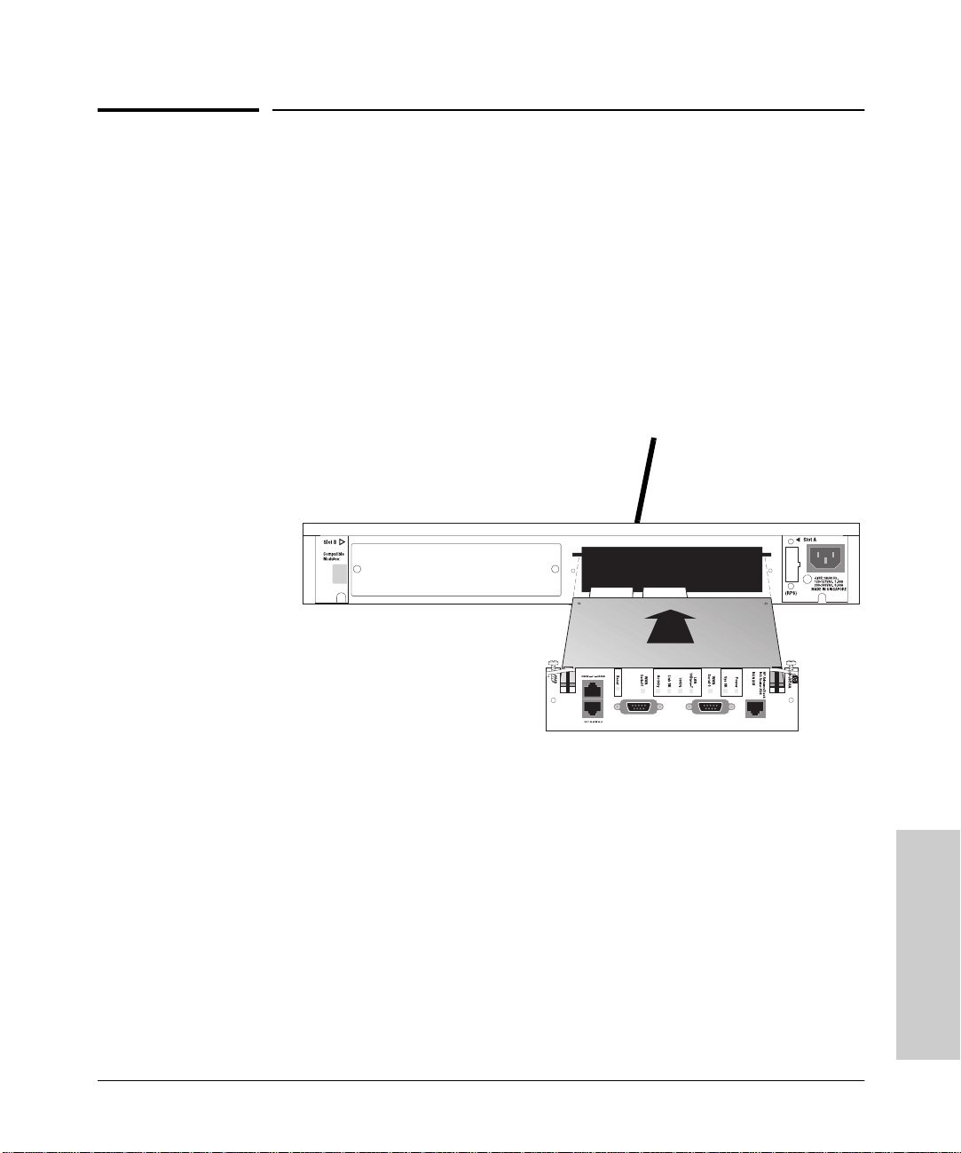
Inserting the HP Internet Router Module into an HP Remote 2C
Troubleshooting
Inserting the HP Internet Router Module
into an HP Remote 2C
In the topology below, HP does not recommend configuring the HP Internet
Router Module for bridging. Instead configure the router to route IP, IPX, and
Appletalk protocols. This is because bridging forwards multicast and broadcast packets from the 100 Mbps network to the much slower T1 or ISDN lines.
This will overload the WAN link with traffic. In routing mode, the Router will
not forward multicast and broadcast packets off of the network.
To A 100VG Network
Back of Remote 2C
HP Internet Router
Module (in either slot
of the Remote 2C)
Service Note Numbers
J3200A-02A
J3201A-02A
J3202A-02A
J3203A-02A
J3204A-02A
J3205A-02A
J3138A-01
Maintenance
4-17
Page 68

Troubleshooting
Router to Router Connections
Router to Router Connections
Please see our web site for technical documents that cover these connections:
■ Leased Line HDLC Connections Between IOS RoutersLeased Line PPP
Connections Between IOS Routers
■ Leased Line PPP Connections Between IOS and HP Routers
■ Frame Relay Connections Between IOS and HP Routers
■ Frame Relay Connections Between IOS and HP Routers
■ Frame Relay Connections Between IOS and HP Routers
■ Frame Relay Connections Between IOS Routers
Our web site address is http://www.hp.com/go/network_city. When the
home page appears, click on Support, Internet Router, then Technical Tips and
these papers are available to view and print.
Maintenance
4-18
Page 69

A
Cable Specifications
B
This appendix provides the following pinout information:
■ Console and Auxiliary Port Signals and Pinouts
■ Synchronous Serial Cable Assemblies and Pinouts
■ ISDN BRI Port and Cable Pinouts
NOTE
All pins not listed in the tables in this appendix are not connected.
If you prefer to order cables, refer to the section “Ordering Information” in
chapter 1 “HP AdvanceStack Internet Router Overview” for ordering
information.
Console and Auxiliary Port Signals and
Cable Specifications
Pinouts
Your router comes with a console and auxiliary cable kit, which contains the
cable and adapters you need to connect a console terminal (an ASCII terminal
or PC running terminal emulation software) or modem to your router. The
console and auxiliary cable kit includes the following items:
■ RJ-45-to-RJ-45 roll-over cable. (See the next section, “Identifying a Roll-
Over Cable” for more information.)
■ RJ-45-to-DB-9 female DTE adapter (labeled “TERMINAL”).
■ RJ-45-to-DB-25 female DTE adapter (labeled “TERMINAL”).
■ RJ-45-to-DB-25 male DCE adapter (labeled “MODEM”).
For console connections, proceed to the section “Console Port Signals and
Pinouts” later in this appendix; for modem connections, proceed to the section
“Auxiliary Port Signals and Pinouts” later in this appendix.
A-1
Page 70

Cable Specifications
Cable Specifications
Console and Auxiliary Port Signals and Pinouts
Identifying a Roll-Over Cable
You can identify a roll-over cable by comparing the two modular ends of
the cable. Holding the cables side-by-side, with the tab at the back, the
wire connected to the pin on the outside of the left plug should be the same
color as the wire connected to the pin on the outside of the right plug. (See
figure A-1). If your cable came from Cisco Systems, pin 1 will be white on one
connector, and pin 8 will be white on the other (a roll-over cable reverses pins
1 and 8, 2 and 7, 3 and 6, and 4 and 5).
Pin 1
Pin 1 and pin 8
should be the
same color
Pin 8
Figure A-1. Identifying a Roll-Over Cable
H3824
A-2
Page 71

Console and Auxiliary Port Signals and Pinouts
Cable Specifications
Console Port Signals and Pinouts
Use the thin, flat, RJ-45-to-RJ-45 roll-over cable and RJ-45-to-DB-9 female DTE
adapter (labeled “TERMINAL”) to connect the console port to a PC running
terminal emulation software. Table A-1 lists the pinouts for the asynchronous
serial console port, the RJ-45-to-RJ-45 roll-over cable, and the RJ-45-to-DB-9
female DTE adapter (labeled “TERMINAL”).
Table A-1. Console Port Signaling and Cabling Using a DB-9 Adapter
Cable Specifications
Console
Port (DTE)
Signal RJ-45 Pin RJ-45 Pin DB-9 Pin Signal
RTS 1
DTR 2 7 6 DSR
TxD 3 6 2 RxD
GND 4 5 5 GND
GND 5 4 5 GND
RxD 6 3 3 TxD
DSR 7 2 4 DTR
CTS 8
a. Pin 1 is connected internally to Pin 8.
RJ-45-to-RJ-45
Roll-Over Cable
a
a
RJ-45-to-DB-9
Terminal Adapter
88 CTS
17 RTS
Console
Device
Use the thin, flat, RJ-45-to-RJ-45 roll-over cable and RJ-45-to-DB-25 female
DTE adapter (labeled “TERMINAL”) to connect the console port to a terminal.
Table A-2 lists the pinouts for the asynchronous serial console port, the RJ-45to-RJ-45 roll-over cable, and the RJ-45-to-DB-25 female DTE adapter (labeled
“TERMINAL”).
A-3
Page 72

Cable Specifications
Console and Auxiliary Port Signals and Pinouts
Table A-2. Console Port Signaling and Cabling Using a DB-25 Adapter
Cable Specifications
Console
Port (DTE)
Signal RJ-45 Pin RJ-45 Pin DB-25 Pin Signal
RTS 1
DTR 2 7 6 DSR
TxD 3 6 3 RxD
GND 4 5 7 GND
GND 5 4 7 GND
RxD 6 3 2 TxD
DSR 7 2 20 DTR
CTS 8
a. You can use the same cabling to connect a console to the auxiliary port.
b. Pin 1 is connected internally to Pin 8.
a
RJ-45-to-RJ-45
Roll-Over Cable
b
b
85 CTS
14 RTS
RJ-45-to-DB-25
Terminal Adapter
Console
Device
Auxiliary Port Signals and Pinouts
Use the thin, flat, RJ-45-to-RJ-45 roll-over cable and RJ-45-to-DB-25 male DCE
adapter (labeled “MODEM”) to connect the auxiliary port to a modem. Figure
A-2 shows how to connect the auxiliary port to a modem. Table A-3 lists the
pinouts for the asynchronous serial auxiliary port, the RJ-45-to-RJ-45 roll-over
cable, and the RJ-45-to-DB-25 male DCE adapter (labeled “MODEM”).
A-4
RJ-45-to-RJ-45
roll-over cable
Router
RJ-45-to-DB-25 adapter
(labeled “MODEM”)
Figure A-2. Connecting the Auxiliary Port to a Modem
Modem
H6094
Page 73

Synchronous Serial Cable Assemblies and Pinouts
Cable Specifications
Table A-3. Auxiliary Port Signaling and Cabling Using a DB-25 Adapter
Auxiliary
Port (DTE)
Signal RJ-45 Pin RJ-45 Pin DB-25 Pin Signal
RTS 1
DTR 2 7 20 DTR
TxD 3 6 3 TxD
GND 4 5 7 GND
GND 5 4 7 GND
RxD 6 3 2 RxD
DSR 7 2 8 DCD
CTS 8
a. Pin 1 is connected internally to Pin 8.
RJ-45-to-RJ-45
Roll-Over Cable
a
1
RJ-45-to-DB-25
Modem Adapter
84 RTS
15 CTS
Modem
Cable Specifications
Synchronous Serial Cable Assemblies
and Pinouts
The illustrations and tables in this section provide assembly drawings and
pinouts for the EIA-530 DTE, EIA/TIA-232, EIA/TIA-449, V.35, and X.21 DTE
and DCE cables, which are used with the synchronous serial WAN port
(labeled “SERIAL”).
EIA-530
Figure A-3 shows the EIA-530 serial cable assembly, and E-4 lists the pinouts.
Arrows indicate signal direction: —> indicates DTE to DCE, and <— indicates
DCE to DTE.
A-5
Page 74

Cable Specifications
Synchronous Serial Cable Assemblies and Pinouts
60-pin connector 25-pin connector
J2-13
J2-25
Cable Specifications
H1972
J2-14
J2-1
Connectors are not to scale
Figure A-3. EIA-530 Serial Cable Assembly
A-6
Page 75

Synchronous Serial Cable Assemblies and Pinouts
Table A-4. EIA-530 DTE Cable Pinouts (DB-60 to DB-25)
60 Pin Signal 25 Pin Signal
Direction
DTE DCE
a
Cable Specifications
Cable Specifications
J1-11
J1-12
J1-28
J1-27
J1-9
J1-10
J1-1
J1-2
J1-3
J1-4
J1-46
J1-47
J1-48
J1-49
J1-5
J1-6
J1-24
J1-23
J1-26
J1-25
TxD/RxD+
TxD/RxD–
RxD/TxD+
RxD/TxD–
RTS/CTS+
RTS/CTS–
CTS/RTS+
CTS/RTS–
DSR/DTR+
DSR/DTR–
Shield_GND
MODE_2
GND
MODE_1
DCD/DCD+
DCD/DCD–
TxC/RxC+
TxC/RxC–
RxC/TxCE+
RxC/TxCE–
J2-2
J2-14
J2-3
J2-16
J2-4
J2-19
J2-5
J2-13
J2-6
J2-22
J2-1
—
—
—
J2-8
J2-10
J2-15
J2-12
J2-17
J2-9
BA(A), TxD+
BA(B), TxD–
BB(A), RxD+
BB(B), RxD–
CA(A), RTS+
CA(B), RTS–
CB(A), CTS+
CB(B), CTS–
CC(A), DSR+
CC(B), DSR–
Shield
—
—
—
CF(A), DCD+
CF(B), DCD–
DB(A), TxC+
DB(B), TxC–
DD(A), RxC+
DD(B), RxC–
—>
—>
<—
<—
—>
—>
<—
<—
<—
<—
Shorted
Shorted
<—
<—
<—
<—
<—
<—
J1-44
J1-45
J1-7
J1-8
J1-13
J1-14
J1-51
J1-52
a. The EIA-530 interface operates in DTE mode only. A DCE cable is not
available for the EIA-530 interface.
LL/DCD
Circuit_GND
DTR/DSR+
DTR/DSR–
TxCE/TxC+
TxCE/TxC–
GND
MODE_DCE——
J2-18
J2-7
J2-20
J2-23
J2-24
J2-11
LL
Circuit_ GND—>–
CD(A), DTR+
CD(B), DTR–
DA(A), TxCE+
DA(B), TxCE–—>—>
—
—
—>
—>
Shorted
A-7
Page 76
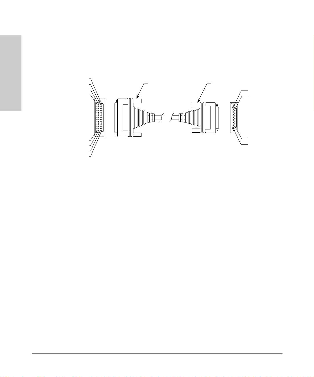
Cable Specifications
Cable Specifications
Synchronous Serial Cable Assemblies and Pinouts
EIA/TIA-232
Figure A-4 shows the EIA/TIA-232 cable assembly. Table A-5 lists the DTE
pinouts. Table A-6 lists the DCE pinouts. Arrows indicate signal direction:
—> indicates DTE to DCE, and <— indicates DCE to DTE.
60-pin connector 25-pin connector
J2-13
J2-25
H1972
J2-14
J2-1
Connectors are not to scale
Figure A-4. EIA/TIA-232 Cable Assembly
A-8
Page 77

Synchronous Serial Cable Assemblies and Pinouts
Cable Specifications
Table A-5. EIA/TIA-232 DCE Cable Pinouts (DB-60 to DB-25)
60 Pin Signal Description Direction 25 Pin Signal
Cable Specifications
J1-50
J1-51
J1-52
J1-46 Shield GND Single – J2-1 Shield GND
J1-41
Shield
J1-36
Shield
J1-42
Shield
J1-35
Shield
J1-34
Shield
J1-45
Shield
J1-33
Shield
J1-37
Shield
MODE_0
GND
MODE_DCE
TxD/RxD
–
RxD/TxD
–
RTS/CTS
–
CTS/RTS
–
DSR/DTR
–
Circuit GND–Twisted pair no. 1 –
DCD/LL
–
TxC/NIL
–
Shorting group – – –
Twisted pair no. 5 —>
Twisted pair no. 9 <—
Twisted pair no. 4 —>
Twisted pair no. 10 <—
Twisted pair no. 11 <—
Twisted pair no. 12 <—
Twisted pair no. 8 <—
J2-2
–
–
–
–
–
–
–
–
Shield
J2-3
Shield
J2-4
Shield
J2-5
Shield
J2-6
Shield
J2-7
Shield
J2-8
Shield
J2-15
Shield
TxD
–
RxD
–
RTS
–
CTS
–
DSR
–
Circuit GND
–
DCD
–
TxC
–
J1-38
Shield
J1-44
Shield
J1-43
Shield
J1-39
Shield
RxC/TxCE
–
LL/DCD
–
DTR/DSR
–
TxCE/TxC
–
Twisted pair no. 7 <—
–
Twisted pair no. 2 —>
–
Twisted pair no. 3 —>
–
Twisted pair no. 6 —>
–
J2-17
Shield
J2-18
Shield
J2-20
Shield
J2-24
Shield
RxC
–
LTST
–
DTR
–
TxCE
–
A-9
Page 78

Cable Specifications
Synchronous Serial Cable Assemblies and Pinouts
Table A-6. EIA/TIA-232 DCE Cable Pinouts (DB-60 to DB-25)
60 Pin Signal Description Direction 25 Pin Signal
Cable Specifications
J1-50
J1-51
J1-46 Shield GND Single – J2-1 Shield GND
J1-36
Shield
J1-41
Shield
J1-35
Shield
J1-42
Shield
J1-43
Shield
J1-45
Shield
J1-44
Shield
J1-39
Shield
J1-40
Shield
MODE_0
GND
RxD/TxD
–
TxD/RxD
–
CTS/RTS
–
RTS/CTS
–
DTR/DSR
–
Circuit GND–Twisted pair no. 1 –
LL/DCD
–
TxCE/TxC
–
NIL/RxC
–
Shorting group – – –
Twisted pair no. 9 <—
Twisted pair no. 5 —>
Twisted pair no. 10 <—
Twisted pair no. 4 —>
Twisted pair no. 3 —>
Twisted pair no. 2 —>
Twisted pair no. 7 —>
Twisted pair no. 6 —>
J2-2
–
–
–
–
–
–
–
–
–
Shield
J2-3
Shield
J2-4
Shield
J2-5
Shield
J2-6
Shield
J2-7
Shield
J2-8
Shield
J2-15
Shield
J2-17
Shield
TxD
–
RxD
–
RTS
–
CTS
–
DSR
–
Circuit GND
DCD
–
TxC
–
RxC
–
A-10
J1-33
Shield
J1-34
Shield
J1-38
Shield
DCD/LL
–
DSR/DTR
–
RxC/TxCE
–
Twisted pair no. 12 <—
–
Twisted pair no. 11 <—
–
Twisted pair no. 8 <—
–
J2-18
Shield
J2-20
Shield
J2-24
Shield
LTST
–
DTR
–
TxCE
–
Page 79

Synchronous Serial Cable Assemblies and Pinouts
Cable Specifications
EIA/TIA-449
Figure A-5 shows the EIA/TIA-449 cable assembly. Table A-7 lists the DTE
pinouts. Table A-8 lists the DCE pinouts. Arrows indicate signal direction:
—> indicates DTE to DCE, and <— indicates DCE to DTE.
Cable Specifications
60-pin connector (J1)
Connectors are not to scale
Figure A-5. EIA/TIA-449 Cable Assembly
37-pin connector (J2)
J2-19
J2-37
H1973
J2-20
J2-1
A-11
Page 80

Cable Specifications
Synchronous Serial Cable Assemblies and Pinouts
Table A-7. EIA/TIA-449 DTE Cable Pinouts (DB-60 to DB-37)
60 Pin Signal Description Direction 37 Pin Signal
Cable Specifications
J1-49
J1-48
J1-51
J1-52
J1-46 Shield_GND Single _ J2-1 Shield GND
J1-11
J1-12
J1-24
J1-23
J1-28
J1-27
J1-9
J1-10
J1-26
J1-25
J1-1
J1-2
J1-44
J1-45
MODE_1
GND
GND
MODE_DCE
TxD/RxD+
TxD/RxD–
TxC/RxC+
TxC/RxC–
RxD/TxD+
RxD/TxD–
RTS/CTS+
RTS/CTS–
RxC/TxCE+
RxC/TxCE–
CTS/RTS+
CTS/RTS–
LL/DCD
Circuit_GND
Shorting group – – –
Shorting group – – –
Twisted pair no. 6 —>
—>
Twisted pair no. 9 <—
<—
Twisted pair no. 11 <—
<—
Twisted pair no. 5 —>
—>
Twisted pair no. 10 <—
<—
Twisted pair no. 1 <—
<—
Twisted pair no. 12 —>
_
J2-4
J2-22
J2-5
J2-23
J2-6
J2-24
J2-7
J2-25
J2-8
J2-26
J2-9
J2-27
J2-10
J2-37
SD+
SD–
ST+
ST–
RD+
RD–
RS+
RS–
RT+
RT–
CS+
CS–
LL
SC
A-12
J1-3
J1-4
J1-7
J1-8
J1-5
J1-6
J1-13
J1-14
J1-15
J1-16
DSR/DTR+
DSR/DTR–
DTR/DSR+
DTR/DSR–
DCD/DCD+
DCD/DCD–
TxCE/TxC+
TxCE/TxC–
Circuit_GND
Circuit_GND
Twisted pair no. 2 <—
<—
Twisted pair no. 4 —>
—>
Twisted pair no. 3 <—
<—
Twisted pair no. 7 —>
—>
Twisted pair no. 9 –
–
J2-11
J2-29
J2-12
J2-30
J2-13
J2-31
J2-17
J2-35
J2-19
J2-20
DM+
DM–
TR+
TR–
RR+
RR–
TT+
TT–
SG
RC
Page 81

Synchronous Serial Cable Assemblies and Pinouts
Cable Specifications
Table A-8. EIA/TIA-449 DCE Cable Pinouts (DB-60 to DB-37)
60 Pin Signal Description Direction 37 Pin Signal
Cable Specifications
J1-49
J1-48
J1-46 Shield_GND Single – J2-1 Shield GND
J1-28
J1-27
J1-13
J1-14
J1-11
J1-12
J1-1
J1-2
J1-24
J1-23
J1-9
J1-10
J1-29
J1-30
J1-7
J1-8
J1-3
J1-4
MODE_1
GND
RxD/TxD+
RxD/TxD–
TxCE/TxC+
TxCE/TxC–
TxD/RxD+
TxD/RxD–
CTS/RTS+
CTS/RTS–
TxC/RxC+
TxC/RxC–
RTS/CTS+
RTS/CTS–
NIL/LL
Circuit_GND
DTR/DSR+
DTR/DSR–
DSR/DTR+
DSR/DTR–
Shorting group – – –
Twisted pair no. 11 <—
<—
Twisted pair no. 7 —>
—>
Twisted pair no. 6 —>
—>
Twisted pair no. 1 <—
<—
Twisted pair no. 9 —>
—>
Twisted pair no. 5 —>
—>
Twisted pair no. 12 —>
–
Twisted pair no. 4 —>
—>
Twisted pair no. 2 <—
<—
J2-4
J2-22
J2-5
J2-23
J2-6
J2-24
J2-7
J2-25
J2-8
J2-26
J2-9
J2-27
J2-10
J2-37
J2-11
J2-29
J2-12
J2-30
SD+
SD–
ST+
ST–
RD+
RD–
RS+
RS–
RT+
RT–
CS+
CS–
LL
SC
DM+
DM–
TR+
TR–
J1-5
J1-6
J1-26
J1-25
J1-15
J1-16
DCD/DCD+
DCD/DCD–
RxC/TxCE+
RxC/TxCE–
Circuit_GND
Circuit_GND
Twisted pair no. 3 —>
—>
Twisted pair no. 10 <—
<—
Twisted pair no. 8 _
_
J2-13
J2-31
J2-17
J2-35
J2-19
J2-20
RR+
RR–
TT+
TT–
SG
RC
A-13
Page 82

Cable Specifications
Synchronous Serial Cable Assemblies and Pinouts
V.3 5
Figure A-6 shows the V.35 cable assembly. Table A-9 lists the DTE pinouts.
Table A-10 lists the DCE pinouts. Arrows indicate signal direction:
—> indicates DTE to DCE, and <— indicates DCE to DTE.
Cable Specifications
60-pin connector (J1)
Connectors are not to scale
Figure A-6. V.35 Cable Assembly
15-pin connector (J2)
J2-B
J2-D
J2-A
J2-C
J2-KK
J2-MM
J2-LL
J2-NN
H1975
A-14
Page 83

Synchronous Serial Cable Assemblies and Pinouts
Cable Specifications
Table A-9. V.35 DTE Cable Pinouts (DB-60 to 34-Pin)
60 Pin Signal Description Direction 34 Pin Signal
Cable Specifications
J1-49
J1-48
J1-50
J1-51
J1-52
J1-53
J1-54
J1-55
J1-56
J1-46 Shield_GND Single – J2-A Frame GND
J1-45
Shield
J1-42
Shield
J1-35
Shield
J1-34
Shield
J1-33
Shield
J1-43
Shield
MODE_1
GND
MODE_0
GND
MODE_DCE
TxC/NIL
RxC_TxCE
RxD/TxD
GND
Circuit_GND–Twisted pair no. 12 –
RTS/CTS
–
CTS/RTS
–
DSR/DTR
–
DCD/LL
–
DTR/DSR
–
Shorting group – – –
Shorting group – – –
Shorting group – – –
Twisted pair no. 9 —>
Twisted pair no. 8 <—
Twisted pair no. 7 <—
Twisted pair no. 6 <—
Twisted pair no. 10 —>
J2-B
–
–
–
–
–
–
Shield
J2-C
Shield
J2-D
Shield
J2-E
Shield
J2-F
Shield
J2-H
Shield
Circuit GND
–
RTS
–
CTS
–
DSR
–
RLSD
–
DTR
–
J1-44
Shield
J1-18
J1-17
J1-28
J1-27
J1-20
J1-19
J1-26
J1-25
J1-24
J1-23
LL/DCD
–
TxD/RxD+
TxD/RxD–
RxD/TxD+
RxD/TxD–
TxCE/TxC+
TxCE/TxC–
RxC/TxCE+
RxC/TxCE–
TxC/RxC+
TxC/RxC–
Twisted pair no. 11 —>
–
Twisted pair no. 1 —>
—>
Twisted pair no. 5 <—
<—
Twisted pair no. 2 —>
—>
Twisted pair no. 4 <—
<—
Twisted pair no. 3 <—
<—
J2-K
ShieldLT–
J2-P
J2-S
J2-R
J2-T
J2-U
J2-W
J2-V
J2-X
J2-Y
J2-AA
SD+
SD–
RD+
RD–
SCTE+
SCTE–
SCR+
SCR–
SCT+
SCT–
A-15
Page 84

Cable Specifications
Synchronous Serial Cable Assemblies and Pinouts
Table A-10. V.35 DCE Cable Pinouts (DB-60 to 34-Pin)
60 Pin Signal Description Direction 34 Pin Signal
Cable Specifications
J1-49
J1-48
J1-50
J1-51
J1-53
J1-54
J1-55
J1-56
J1-46 Shield_GND Single – J2-A Frame GND
J1-45
Shield
J1-35
Shield
J1-42
Shield
J1-43
Shield
J1-44
Shield
J1-34
Shield
MODE_1
GND
MODE_0
GND
TxC/NIL
RxC_TxCE
RxD/TxD
GND
Circuit_GND–Twisted pair no. 12 –
CTS/RTS
–
RTS/CTS
–
DTR/DSR
–
LL/DCD
–
DSR/DTR
–
Shorting group – – –
Shorting group – – –
Shorting group – – –
Twisted pair no. 8 <—
Twisted pair no. 9 —>
Twisted pair no. 10 —>
Twisted pair no. 11 —>
Twisted pair no. 7 <—
J2-B
–
–
–
–
–
–
Shield
J2-C
Shield
J2-D
Shield
J2-E
Shield
J2-F
Shield
J2-H
Shield
Circuit GND
–
RTS
–
CTS
–
DSR
–
RLSD
–
DTR
–
A-16
J1-33
Shield
J1-28
J1-27
J1-18
J1-17
J1-26
J1-25
J1-22
J1-21
J1-20
J1-19
DCD/LL
–
RxD/TxD+
RxD/TxD–
TxD/RxD+
TxD/RxD–
RxC/TxCE+
RxC/TxCE–
NIL/RxC+
NIL/RxC–
TxCE/TxC+
TxCE/TxC–
Twisted pair no. 6 <—
–
Twisted pair no. 5 <—
<—
Twisted pair no. 1 —>
—>
Twisted pair no. 4 <—
<—
Twisted pair no. 3 —>
—>
Twisted pair no. 2 —>
—>
J2-K
Shield
J2-P
J2-S
J2-R
J2-T
J2-U
J2-W
J2-V
J2-X
J2-Y
J2-AA
LT
–
SD+
SD–
RD+
RD–
SCTE+
SCTE–
SCR+
SCR–
SCT+
SCT–
Page 85

Synchronous Serial Cable Assemblies and Pinouts
Cable Specifications
X.21
Figure A-7 shows the X.21 cable assembly. Table A-11 lists the DTE pinouts.
Table A-12 lists the DCE pinouts.
—> indicates DTE to DCE, and <— indicates DCE to DTE.
Arrows indicate signal direction:
Cable Specifications
1-46
1-45
1-16
1-15
J1-1
1-30
1-31
1-60
Connectors are not to scale
Figure A-7. X.21 Cable Assembly
60-pin connector (J1)
15-pin connector (J2)
J2-8
J2-15
H1974
J2-9
J2-1
A-17
Page 86

Cable Specifications
Synchronous Serial Cable Assemblies and Pinouts
Table A-11. X-21 DTE Cable Pinouts (DB-60 to DB-15)
60 Pin Signal Description Direction 15 Pin Signal
Cable Specifications
J1-48
J1-47
J1-51
J1-52
J1-46 Shield_GND Single – J2-1 Shield GND
J1-11
J1-12
J1-9
J1-10
J1-28
J1-27
J1-1
J1-2
J1-26
J1-25
J1-15
Shield
GND
MODE_2
GND
MODE_DCE
TxD/RxD+
TxD/RxD–
RTS/CTS+
RTS/CTS–
RxD/TxD+
RxD/TxD–
CTS/RTS+
CTS/RTS–
RxC/TxCE+
RxC/TxCE–
Control_GND–Twisted pair no. 4 –
Shorting group – – –
Shorting group – – –
Twisted pair no. 3 —>
Twisted pair no. 2 —>
Twisted pair no. 6 <—
Twisted pair no. 1 <—
Twisted pair no. 5 <—
—>
—>
<—
<—
<—
–
J2-2
J2-9
J2-3
J2-10
J2-4
J2-11
J2-5
J2-12
J2-6
J2-13
J2-8
Shield
Transmit+
Transmit–
Control+
Control–
Receive+
Receive–
Indication+
Indication–
Timing+
Timing–
Control GND
–
A-18
Page 87

Synchronous Serial Cable Assemblies and Pinouts
Cable Specifications
Table A-12. X.21 DCE Cable Pinouts (DB-60 to DB-15)
60 Pin Signal Description Direction 15 Pin Signal
Cable Specifications
J1-48
J1-47
J1-46 Shield_GND Single – J2-1 Shield GND
J1-28
J1-27
J1-1
J1-2
J1-11
J1-12
J1-9
J1-10
J1-24
J1-23
J1-15
Shield
GND
MODE_2
RxD/TxD+
RxD/TxD–
CTS/RTS+
CTS/RTS–
TxD/RxD+
TxD/RxD–
RTS/CTS+
RTS/CTS–
TxC/RxC+
TxC/RxC–
Control_GND–Twisted pair no. 5 –
Shorting group – – –
Twisted pair no. 6 <—
Twisted pair no. 1 <—
Twisted pair no. 3 —>
Twisted pair no. 2 —>
Twisted pair no. 4 —>
<—
<—
—>
—>
—>
–
J2-2
J2-9
J2-3
J2-10
J2-4
J2-11
J2-5
J2-12
J2-6
J2-13
J2-8
Shield
Transmit+
Transmit–
Control+
Control–
Receive+
Receive–
Indication+
Indication–
Timing+
Timing–
Control GND
–
A-19
Page 88

Cable Specifications
Synchronous Serial Cable Assemblies and Pinouts
ISDN BRI Port and Cable Pinouts
Table A-13 lists the ISDN BRI port pinouts. The straight-through RJ-45-to-RJ-45
cable, used to connect to the ISDN BRI port, is not included.
Table A-13. BRI Port (RJ-45) Pinout
Cable Specifications
b
RJ-45
a
8 Pin
3 Transmit Receive +
4 Receive Transmit +
5 Receive Transmit –
6 Transmit Receive –
a. Pins 1, 2, 7, and 8 are not used.
b. TE refers to terminal terminating layer 1 aspects of TE1, TA, and NT2 functional
groups.
c. NT refers to network terminating layer 1 aspects of NT1 and NT2 functional groups.
TE
NT
c
Polarity
A-20
Page 89

HP J3138A Specifications
Physical
Width: 15.5 cm (6.1 in)
B
Depth: 11.8 cm (4.6 in)
Height: 4.4 cm (1.7 in)
Weight (without Modules or RPS: 0.13 kg (0.28 lbs)
Power Consumption
+5 V 4.5 A max.
+12 V 500 mA max.
-12 V 300 mA max.
Total Power Consumption 25 W max.
Environmental
Operating Non-Operating
Temperature 0
o
C to 55oC
o
F to 131oF)
(32
o
40
C to 70oC
(-40
o
F to 158oF)
HP J3138A Specifications
Relative Humidity
(noncondensing)
Maximum Altitude 4.6 Km (15,000 ft) 4.6 Km (15,000 ft)
15 to 95%
o
C (104oF)
at 40
15 to 90%
at 65oC (149oF)
B-1
Page 90

HP J3138A Specifications
Connectors
The RJ-45 twisted-pair ports are compatible with the IEEE 802.3 Type
10Base-T standard.
Electromagnetic
Emissions: FCC part 15 Class A
Immunity: See the Declaration of Conformity for details at the end of the Safety
Safety: Complies with:
CISPR-22 Class A / EN 55022 Class A
VCCI Level I
and Regulatory Statements in the Switching Hubs manual.
IEC 950: (1991) + A1, A2 / .EN60950 I (1992) + A1, A2
Acoustic Noise Not Applicable
HP J3138A Specifications
B-2
Page 91

Safety and Regulatory Statements
Safety Information
Safety Symbols.
Documentation reference symbol. If the product is marked with this
symbol, refer to the product documentation to get more information
about the product.
WARNING A WARNING in the manual denotes a hazard that can cause injury
or death.
CAUTION A CAUTION in the manual denotes a hazard that can damage
equipment.
Do not proceed beyond a WARNING or CAUTION notice until you have understood the
hazardous conditions and have taken appropriate steps.
C
Grounding.
These are safety class I products and have protective earthing terminals. There
must be an uninterruptible safety earth ground from the main power source
to the product's input wiring terminals, power cord, or supplied power cord
set. Whenever it is likely that the protection has been impaired, disconnect
the power cord until the ground has been restored.
For LAN cable grounding:
■ If your LAN covers an area served by more than one power distribution
system, be sure their safety grounds are securely interconnected.
■ LAN cables may occasionally be subject to hazardous transient voltages
(such as lightning or disturbances in the electrical utilities power grid).
Handle exposed metal components of the network with caution.
Servicing.
There are no user-serviceable parts inside these products. Any servicing,
adjustment, maintenance, or repair must be performed only by service-trained
personnel.
These products do not have a power switch; they are powered on when the
power cord is plugged in.
C-1
Safety and Regulatory
Statements
Page 92

Safety and Regulatory Statements
Informations concernant la sécurité
Informations concernant la sécurité
Symboles de sécurité
WARNING Dans la documentation, un WARNING indique un danger susceptible
CAUTION Un texte de mise en garde intitulé CAUTION indique un danger
Ne continuez pas au-delà d’une rubrique WARNING ou CAUTION avant d’avoir bien
compris les conditions présentant un danger et pris les mesures appropriées.
Cet appareil est un produit de classe I et possède une borne de mise à la terre.
La source d’alimentation principale doit être munie d’une prise de terre de
sécurité installée aux bornes du câblage d’entrée, sur le cordon d'alimentation
ou le cordon de raccordement fourni avec le produit. Lorsque cette protection
semble avoir été endommagée, débrancher le cordon d’alimentation jusqu’à
ce que la mise à la terre ait été réparée.
Symbole de référence à la documentation. Si le produit est marqué
de ce symbole, reportez-vous à la documentation du produit afin
d’obtenir des informations plus détaillées.
d’entraîner des dommages corporels ou la mort.
susceptible de causer des dommages à l’équipement.
Safety and Regulatory
Mise à la terre du câble de réseau local:
■ si votre réseau local s’étend sur une zone desservie par plus d’un système
de distribution de puissance, assurez-vous que les prises de terre de
sécurité soient convenablement interconnectées.
Statements
■ Les câbles de réseaux locaux peuvent occasionnellement être soumis à
des surtensions transitoires dangereuses (telles que la foudre ou des
perturbations dans le réseau d’alimentation public). Manipulez les
composants métalliques du réseau avec précautions.
Aucune pièce contenue à l’intérieur de ce produit ne peut être réparée par
l’utilisateur. Tout dépannage, réglage, entretien ou réparation devra être confié exclusivement à un personnel qualifié.
Cet appareil ne comporte pas de commutateur principal ; la mise sous tension
est effectuée par branchement du cordon d’alimentation.
C-2
Page 93

Safety and Regulatory Statements
Hinweise zur Sicherheit
Hinweise zur Sicherheit
Sicherheitssymbole.
Symbol für Dokumentationsverweis. Wenn das Produkt mit diesem
Symbol markiert ist, schlagen Sie bitte in der Produktdokumentation
nach, um mehr Informationen über das Produkt zu erhalten.
WARNING Eine WARNING in der Dokumentation symbolisiert eine Gefahr, die
Verletzungen oder sogar Todesfälle verursachen kann.
CAUTION CAUTION in der Dokumentation symbolisiert eine Gefahr, die das
Gerät beschädigen kann.
Fahren Sie nach dem Hinweis WARNING oder CAUTION erst fort, nachdem Sie den
Gefahrenzustand verstanden und die entsprechenden Maßnahmen ergriffen haben.
Dies ist ein Gerät der Sicherheitsklasse I und verfügt über einen schützenden
Erdungsterminal. Der Betrieb des Geräts erfordert eine ununterbrochene
Sicherheitserdung von der Hauptstromquelle zu den Geräteingabeterminals,
den Netzkabeln oder dem mit Strom belieferten Netzkabelsatz voraus. Sobald
Grund zur Annahme besteht, daß der Schutz beeinträchtigt worden ist, das
Netzkabel aus der Wandsteckdose herausziehen, bis die Erdung
wiederhergestellt ist.
Für LAN-Kabelerdung:
■ Wenn Ihr LAN ein Gebiet umfaßt, das von mehr als einem
Stromverteilungssystem beliefert wird, müssen Sie sich vergewissern,
daß die Sicherheitserdungen fest untereinander verbunden sind.
■ LAN-Kabel können gelegentlich gefährlichen Übergangsspannungen
ausgesetzt werden (beispielsweise durch Blitz oder Störungen in dem
Starkstromnetz des Elektrizitätswerks). Bei der Handhabung exponierter
Metallbestandteile des Netzwerkes Vorsicht walten lassen.
Safety and Regulatory
Statements
Dieses Gerät enthält innen keine durch den Benutzer zu wartenden Teile.
Wartungs-, Anpassungs-, Instandhaltungs- oder Reparaturarbeiten dürfen nur
von geschultem Bedienungspersonal durchgeführt werden.
Dieses Gerät hat keinen Netzschalter; es wird beim Anschließen des
Netzkabels eingeschaltet.
C-3
Page 94

Safety and Regulatory Statements
Considerazioni sulla sicurezza
Considerazioni sulla sicurezza
Simboli di sicurezza.
WARNING La dicitura WARNING denota un pericolo che può causare lesioni o
CAUTION La dicitura CAUTION denota un pericolo che può danneggiare le
Non procedere oltre un avviso di WARNING o di CAUTION prima di aver compreso le
condizioni di rischio e aver provveduto alle misure del caso.
Questo prodotto è omologato nella classe di sicurezza I ed ha un terminale
protettivo di collegamento a terra. Dev’essere installato un collegamento a
terra di sicurezza, non interrompibile che vada dalla fonte d’alimentazione
principale ai terminali d’entrata, al cavo d’alimentazione oppure al set cavo
d’alimentazione fornito con il prodotto. Ogniqualvolta vi sia probabilità di
danneggiamento della protezione, disinserite il cavo d’alimentazione fino a
quando il collegamento a terra non sia stato ripristinato.
Simbolo di riferimento alla documentazione. Se il prodotto è
contrassegnato da questo simbolo, fare riferimento alla
documentazione sul prodotto per ulteriori informazioni su di esso.
morte.
attrezzature.
Safety and Regulatory
Per la messa a terra dei cavi LAN:
■ se la vostra LAN copre un’area servita da più di un sistema di distribuzione
elettrica, accertatevi che i collegamenti a terra di sicurezza siano ben
collegati fra loro;
Statements
■ i cavi LAN possono occasionalmente andare soggetti a pericolose tensioni
transitorie (ad esempio, provocate da lampi o disturbi nella griglia
d’alimentazione della società elettrica); siate cauti nel toccare parti
esposte in metallo della rete.
Nessun componente di questo prodotto può essere riparato dall’utente.
Qualsiasi lavoro di riparazione, messa a punto, manutenzione o assistenza va
effettuato esclusivamente da personale specializzato.
Questo apparato non possiede un commutatore principale; si mette scotto
tensione all’inserirsi il cavo d’alimentazione.
C-4
Page 95

Safety and Regulatory Statements
Consideraciones sobre seguridad
Consideraciones sobre seguridad
Símbolos de seguridad.
Símbolo de referencia a la documentación. Si el producto va
marcado con este símbolo, consultar la documentación del
producto a fin de obtener mayor información sobre el producto.
WARNING Una WARNING en la documentación señala un riesgo que podría
resultar en lesiones o la muerte.
CAUTION Una CAUTION en la documentación señala un riesgo que podría
resultar en averías al equipo.
No proseguir después de un símbolo de WARNING o CAUTION hasta no haber entendido
las condiciones peligrosas y haber tomado las medidas apropiadas.
Este aparato se enmarca dentro de la clase I de seguridad y se encuentra
protegido por una borna de puesta a tierra. Es preciso que exista una puesta
a tierra continua desde la toma de alimentación eléctrica hasta las bornas de
los cables de entrada del aparato, el cable de alimentación o el juego de cable
de alimentación suministrado. Si existe la probabilidad de que la protección
a tierra haya sufrido desperfectos, desenchufar el cable de alimentación hasta
haberse subsanado el problema.
Puesta a tierra del cable de la red local (LAN):
■ Si la LAN abarca un área cuyo suministro eléctrico proviene de más de
una red de distribución de electricidad, cerciorarse de que las puestas a
tierra estén conectadas entre sí de modo seguro.
■ Es posible que los cables de la LAN se vean sometidos de vez en cuando
a voltajes momentáneos que entrañen peligro (rayos o alteraciones en la
red de energía eléctrica). Manejar con precaución los componentes de
metal de la LAN que estén al descubierto.
Safety and Regulatory
Statements
Este aparato no contiene pieza alguna susceptible de reparación por parte del
usuario. Todas las reparaciones, ajustes o servicio de mantenimiento debe
realizarlos solamente el técnico.
Este producto no tiene interruptor de potencia; se activa cuando se enchufa
el cable de alimentación.
C-5
Page 96

Safety and Regulatory Statements
Safety Information (Japanese)
Safety Information
(Japanese)
Safety and Regulatory
Statements
C-6
Page 97

Safety and Regulatory Statements
Regulatory Statements
Regulatory Statements
FCC Class A Statement (for U.S.A. Only) when using unshielded
cables.
This equipment has been tested and found to comply with the limits for a Class
A digital device, pursuant to Part 15 of the FCC Rules. These limits are
designed to provide reasonable protection against harmful interference when
the equipment is operated in a commercial environment. This equipment
generates, uses, and can radiate radio frequency energy and, if not installed
and used in accordance with the instruction manual, may cause harmful
interference to radio communications. Operation of this equipment in a
residential area may cause harmful interference in which case the user will be
required to correct the interference at his own expense.
FCC Statement (For U.S.A. Only)
Federal Communications Commission Radio Frequency Interference
Statement.
Warning: This equipment generates, uses, and can radiate radio frequency
energy. If it is not installed and used in accordance with the instruction
manual, it may cause interference to radio communications. It has been tested
and found to comply with the limits for a Class A computing device pursuant
to Part 15 of FCC Rules, which are designed to provide reasonable protection
against such interference when operated in a commercial environment.
If this equipment causes interference to radio reception (which can be
determined by unplugging the power cord from the equipment) try these
measures: Re-orient the receiving antenna. Relocate the equipment with
respect to the receiver. Plug the equipment and receiver into different branch
circuits. Consult your dealer or an experienced technician for additional
suggestions.
Safety and Regulatory
Statements
C-7
Page 98

Safety and Regulatory
Safety and Regulatory Statements
Regulatory Statements
Statements
FCC Part 68. General Requirements
■ This equipment complies with part 68 of the FCC rules. On the back of
this equipment is a label that contains, among other information, the FCC
registration number and ringer equivalence number (REN) for this equipment. If requested, this information must be provided to the telephone
company.
This Model J3138A has the FCC Digital Interface Code of 02IS5. The FCC
Service Order Code is 6.0N.
■ The REN is used to determine the quantity of devices which may be
connected to the telephone line. Excessive REN’s on the telephone line
may result in the devices not ringing in response to an incoming call. In
most, but not all areas, the sum of the REN’s should not exceed five (5.0).
To be certain of the number of devices that may be connected to the line,
as determined by the total REN’s, contact the telephone company to
determine the maximum REN for the calling area.
No USOC jacks have yet been specified for ISDN equipment.
■
An FCC compliant telephone cord and modular plug is provided with this
equipment. This equipment is designed to be connected to the telephone
network or premises wiring using a compatible modular jack which is Part
68 compliant.
■ This equipment cannot be used on telephone company-provided coin
service. Connection to Party Line Service is subject to state tariffs.
If this equipment causes harm to the telephone network, the telephone
■
company will notify you in advance that temporary discontinuance of
service may be required. If advance notice isn’t practical, the telephone
company will notify the customer as soon as possible. Also, you will be
advised of your right to file a complaint with the FCC if you believe it is
necessary.
■ The telephone company may make changes in its facilities, equipment,
operations, or procedures that could affect the operation of the equipment. If this happens, the telephone company will provide advance notice
in order for you to make the necessary modifications in order to maintain
uninterrupted service.
■ If trouble is experienced with this equipment, please contact
Hewlett-Packard Company warranty information. If the trouble is causing
harm to the telephone network, the telephone company may request you
remove the equipment from the network until the problem is resolved.
■ No repairs can be done by the customer.
■ It is recommended that the customer install and AC surge arrestor in the
AC outlet to which this device is connected. This is to avoid damaging the
equipment caused by local lightning strikes and other electrical surges.
C-8
Page 99

For service:
Hewlett-Packard Company
3625 Cincinnati Avenue
Rocklin, California 95765-1288
VCCI Class 1 (For Japan Only).
Safety and Regulatory Statements
Regulatory Statements
Note
NOTE
This is a class A product. In a domestic environment, this product may cause
radio interference, in which case the user may be required to take adequate
measures.
Complies with Canadian EMC Class A requirements.
European Community
This equipment complies with ISO/IEC Guide 22 and EN55022 Class A with
unshielded cables and EN55022.
With unshielded cables this is a Class A product. In a domestic environment,
this product may cause radio interference, in which case the user may be
required to take adequate measure.
Canada
This product complies with Class A Canadian EMC requirements when using
unshielded cables and Class B EMC requirements when using shielded cables.
This is a class A product. In a domestic environment, this product may cause
radio interference, in which case the user may be required to take adequate
measures.
Safety and Regulatory
Statements
C-9
Page 100

 Loading...