

Page 1

AD380A and AD381A PCIe 2-Port Gigabit Ethernet Card Installation Guide
HP Part Number: 5991–5976
Published: June 2007
Page 2

Legal Notices
© Copyright 2007 Hewlett-Packard Development Company, L.P.
Confidential computer software. Valid license from HP required for possession, use or copying. Consistent with FAR 12.211 and 12.212, Commercial
Computer Software, Computer Software Documentation, and Technical Data for Commercial Items are licensed to the U.S. Government under
vendor's standard commercial license.
The information contained herein is subject to changewithoutnotice. The only warranties for HP products and services are set forth in the express
warranty statements accompanying such products and services. Nothing herein should be construed as constituting an additional warranty. HP
shall not be liable for technical or editorial errors or omissions contained herein.
Microsoft and Windows are U.S. registered trademarks of Microsoft Corporation. Intel and Itanium are registered trademarks of Intel Corporation
or its subsidiaries in the United States and other countries.
Java is a U.S. trademark of Sun Microsystems, Inc.
UNIX is a registered trademark of The Open Group.
Page 3

Table of Contents
About this document..........................................................................................................9
1 Hardware and software installation procedures......................................................11
Installing the hardware.........................................................................................................................11
Access the system card bay.............................................................................................................11
Install the card.................................................................................................................................11
Connect the card to the network.....................................................................................................12
Installing the software...........................................................................................................................14
Prepare for the Installation..............................................................................................................15
Open the Computer Management program...................................................................................15
Install the adapter driver.................................................................................................................15
Ping a host on the network..............................................................................................................16
Troubleshooting....................................................................................................................................16
Check the connection.......................................................................................................................17
2 Specifications and Regulatory Information................................................................19
Card Specifications...............................................................................................................................19
Cable specifications...............................................................................................................................20
AD380A (copper).............................................................................................................................20
AD381A (fiber)................................................................................................................................20
RJ-45 pinouts and crossover function (applies to AD380A only).........................................................20
10/100 pinouts using internal, straight-through crossover.............................................................20
10/100 pinouts using external crossover through twisted-pair media............................................21
Gigabit over copper pinouts using internal crossover....................................................................22
Gigabit over copper pinouts using external crossover through twisted pair media......................23
Regulatory compliance information.....................................................................................................24
Regulatory compliance identification numbers..............................................................................24
Federal Communications Commission notice................................................................................24
Class A equipment...........................................................................................................................24
Class B equipment...........................................................................................................................24
Declaration of conformity for products marked with the FCC logo, United States only...............25
Modifications...................................................................................................................................25
Canadian notice (Avis Canadien).........................................................................................................25
European Union regulatory notice.......................................................................................................25
Japanese notice......................................................................................................................................26
Korean Class A notice...........................................................................................................................27
Korean Class B notice............................................................................................................................27
BSMI notice...........................................................................................................................................27
Disposal of waste equipment by users in private households in the European Union.......................27
Electrostatic discharge..........................................................................................................................28
Preventing electrostatic discharge...................................................................................................28
Grounding methods to prevent electrostatic discharge..................................................................28
Table of Contents 3
Page 4

4
Page 5

List of Figures
1-1 Inserting the card...........................................................................................................................12
1-2 Connecting the AD380A (copper) card.........................................................................................13
1-3 Connecting the AD381A (fiber) card.............................................................................................14
1-4 Ipconfig command output ............................................................................................................16
1-5 Adapter error display in the taskbar.............................................................................................16
1-6 Adapter error display in the Network Connections window.......................................................17
2-1 10/100 pinouts using internal, straight-through crossover...........................................................21
2-2 10/100 pinouts using external crossover through twisted-pair media..........................................22
2-3 Gigabit over copper pinouts using internal crossover..................................................................23
2-4 Gigabit over copper pinouts using external crossover through twisted pair media....................24
2-5 Harmonized European standards product marking....................................................................26
2-6 Non-telecom and EU harmonized telecom products marking.....................................................26
2-7 Japanese product notice................................................................................................................26
2-8 Korean Class A notice...................................................................................................................27
2-9 Korean Class B notice....................................................................................................................27
2-10 BSMI notice....................................................................................................................................27
2-11 EU waste disposal marking...........................................................................................................27
5
Page 6

6
Page 7

List of Tables
2-1 AD380A and AD381A card specifications....................................................................................19
2-2 Operating distances for AD381A adapter.....................................................................................20
7
Page 8

8
Page 9

About this document
The instructions in this document apply to the AD380A (copper) and AD381A (fiber) 2-Port GbE
Ethernet cards for Windows™ and Linux systems. You can download the driver at:
http://www.hp.com/support/itaniumservers
Audience
This document is for those who install and configure network interface cards.
Organization
This document is organized as follows:
Chapter 1
Chapter 2
Describes the steps to install and configure the AD380A and AD381A 2-Port GbE Ethernet
card.
Provides information about the physical and environmental specifications of the AD381A
2-Port GbE Ethernet card.
9
Page 10

10
Page 11

1 Hardware and software installation procedures
The HP AD380A (copper) and AD381A (fiber) PCI Express Dual Port Gigabit Server Adapters
are high-performance, low-profile PCI Express Ethernet adapters that deliver up to 1000 Mb/s
Ethernet over twisted-pair copper cabling or optical fiber cabling. They have a fully integrated
controller capable of auto-negotiating a link at 10, 100, or 1000 Mb/s. Network connections are
made through two RJ-45 connectors (AD380A) or two duplex LC connectors (AD381A). LED
indicators show the link speed and activity. These adapters are supported on selected HP Integrity
servers. You can add or replace them in your system without shutting down or rebooting, using
a process called Online Addition and Replacement (OLAR). However, they must be installed in
a PCI Express slot.
If your AD380A or AD381A card is factory installed, you do not need to perform the hardware
and software installation steps described in this chapter. However, you need to configure the
card's IP address and possibly set other parameters and options, such as those mentioned in the
Network Card Configuration worksheet.
Installing the hardware
The following instructions guide you through the hardware installation process. These instructions
assume you are not using the OLAR process.
Access the system card bay
To access the system card bay, complete the following steps:
1. If the system is running, issue the sync command. Then, shut down the system by executing
the shutdown -h command. Enter Y to continue to the shutdown prompt.
2. Wait for the system to shut down completely, and then power off the system by pressing
the system off button. Ensure that the system is grounded, and unplug the server power
cord.
WARNING! You must turn off and unplug the power to the HP server before removing
its cover. Failure to do so could inflict a dangerous shock to you and may damage the adapter
or the server.
3. Open the system to gain access to the PCIe backplane.
4. Select an unused PCIe slot and remove the slot cover.
Install the card
To install the card, complete the following steps:
1. Check the latest 1 Gb Ethernet support matrix to see the systems that support this card, how
many cards are allowed per system, and if any software updates are needed. The support
matrix is available in the “I/O Cards and Networking Software” section at:
http://docs.hp.com
2. Record the serial number and MAC address located on the card for future reference.
CAUTION: Electrostatic discharge can damage electronic components. You must observe
antistatic precautions and wear electrostatic discharge (ESD) straps before installing the
card. Refer to the section about electrostatic discharge in Chapter 2 for more information.
3. Grasp the card by its edges or faceplate with both hands. Insert the card into the slot and
firmly, but gently, press the card in until it is fully seated (see Figure 1–1).
Installing the hardware 11
Page 12
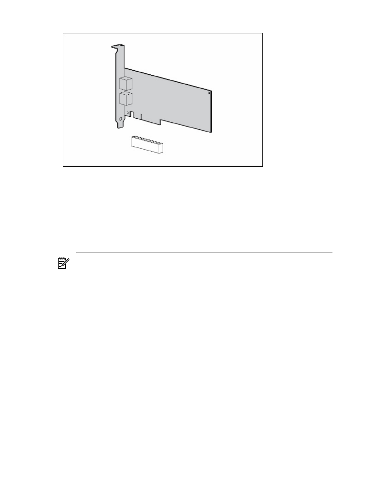
Figure 1-1 Inserting the card
4. Secure the adapter bracket, replace the access panel, and plug in the system power cord.
Connect the card to the network
To connect the card to the network, complete the following steps:
1. Attach the network cable (or cables) to the card, ensuring that the tab on each plug clicks
into position, indicating proper seating.
• For AD380A adapters (copper), the cabling must be Cat 5 UTP or better with RJ-45
connectors (see Figure 1–2).
NOTE: The AD380A adapter can use existing UTP CAT5 cable to deliver Gigabit
Ethernet over copper, according to the IEEE 802.3ab specifications. For new installations,
CAT5e (enhanced CAT5) cable is recommended.
• For AD381A adapters (fiber), the cabling can be either 62.5 micron or 50 micron
multimode fiber optic (MMF) cable with LC connectors (see Figure 1–3). If the remote
connection is type SC, you will need an LC-to-SC conversion cable.
12 Hardware and software installation procedures
Page 13

Figure 1-2 Connecting the AD380A (copper) card
Installing the hardware 13
Page 14

Figure 1-3 Connecting the AD381A (fiber) card
Refer to the tables in the next chapter for maximum operating distances.
2. Attach the free end of the LAN cable (or cables) to any unused port on the Gigabit switch.
Ensure that the switch is configured to support any new connections.
If you are using Jumbo Ethernet frames, ensure that the following conditions exist:
• All end stations on a given LAN have the same maximum transmission unit (MTU)
setting.
• Intermediate stations such as switch ports in your LAN have an MTU equal to or greater
than the end station’s MTU.
3. Ensure that the power cable is connected to system.
4. Power up the system.
NOTE: To obtain updates for the adapter driver, check the HP Driver Support site:
http://www.hp.com/support/itaniumservers.
Installing the software
HP Integrity servers automatically detect and configure PCI-compliant adapters when restarting.
The adapter IRQ level is automatically set by the Extensible Firmware Interface (EFI) each time
the server restarts. If configuration problems are encountered, see the HP Support site:
http://support.hp.com/.
14 Hardware and software installation procedures
Page 15

Prepare for the Installation
After installing the adapter in the server and booting the system, you must install the correct
driver. You can download the driver from the Web or get it from the HP SmartSetup media that
came with the adapter.
NOTE: When using the HP SmartSetup media, the Hardware Update Wizard finds the driver
automatically.
To download from the Web, complete the following steps:
1. Go to http://www.hp.com/support/itaniumservers.
2. Select one of the HP Integrity servers that supports this adapter (for example, rx2660).
3. Click Download drivers and software.
4. Click the link that describes the server operating system.
5. Click Driver-NIC.
6. Select the appropriate driver.
7. Download the driver to the server or to another system with a floppy or DVD writer.
Open the Computer Management program
Once the driver is available, open the Computer Management program by clicking Start >
Programs > Administrative Tools > Computer Management.
If the Programs menu displays Administrative Tools, skip this section and go to the next section
and install the adapter driver using the Computer Management software. If the Programs menu
does not display Administrative Tools, complete the following steps:
1. Right-click on the system taskbar.
2. Select Properties.
3. Click the Start Menu tab.
4. Click the Start menu radio button.
5. Click Customize.
6. Click the Advanced tab.
7. Select Display Administrative Tools as a Start Menu item.
8. Click Okay.
9. Click Okay again.
10. Click Start > Programs > Administrative Tools > Computer Management.
Install the adapter driver
To install the adapter driver, complete the following steps:
1. In the left panel of the Computer Management window, under System Tools, click Device
Manager.
2. In the right panel of Computer Management, under Network Adapters, double-click the
name of the adapter you just installed.
3. Click the Driver tab.
4. Click Update Driver..., and the Hardware Update Wizard displays.
5. Select No, not this time when prompted to let Windows find the driver. Then click Next.
6. Select Install the software automatically (Recommended) and click Next.
7. Click Finish to close the Hardware Update Wizard.
8. The driver is now installed and the device Properties page displays the new driver version.
Installing the software 15
Page 16

Ping a host on the network
Once the adapter is properly connected to the network, ensure that its IP addresses is consistent
with your network by completing the following steps:
1. Click Start > Run to open the Run dialog box.
2. Type cmd in the Run dialog box and click OK to run the command.
3. At the prompt, type ipconfig and press Enter. This command displays all of the IP
addresses, subnet masks, and default gateways configured for the server (see Figure 1–4).
Figure 1-4 Ipconfig command output
4. Now use the ping command to verify adapter connectivity. Use the adapter's IP address
(that was displayed as output from the ipconfig command in Step 3) as your input for
the ping command.
5. Once the adapter is pinged and indicates no problems, ping another host on the same
network. If the server is within the same IP group and subnet mask as the target host and
valid replies are not received, check the network parameters to ensure that the server IP
address and subnet mask are correct.
Troubleshooting
This section describes some of the methods you can use to solve problems you may have with
the operation of your AD380A or AD381A adapter.
During system startup, network interface cards (NICs) attempt to load the latest available drivers.
If there is a problem after the system has booted and configured the adapters (and as long as
Show Icon in notification area when connected is enabled in the Network Properties window),
you may see the following display in the system taskbar:
Figure 1-5 Adapter error display in the taskbar
16 Hardware and software installation procedures
Page 17

IMPORTANT: This display indicates that the adapter is not connected to the network. Verify
that the adapter is properly connected using the appropriate cable.
Check the connection
In some cases, the operating system may not even display the network icon in the system taskbar.
To verify network connections in this situation, complete the following steps:
1. Click Start > Settings > Control Panel.
2. Double-click Network Connections.
3. If an adapter is not connected to the network, a red X appears over its network icon in the
Network Connections window (see Figure 1–6).
Figure 1-6 Adapter error display in the Network Connections window
4. Once again, verify that the adapter is properly connected using either Category 5 or better
cable (for AD380A) or fiber optic cable (for AD381A). Once the adapter is connected to a
viable network, the red X should go away.
Troubleshooting 17
Page 18

18
Page 19

2 Specifications and Regulatory Information
This chapter provides an overview of the AD380A and AD381A 2-Port GbE Ethernet cards and
lists their physical and environmental specifications.
Card Specifications
Adapter specs for the AD380A and AD381A are as follows:
Table 2-1 AD380A and AD381A card specifications
DescriptionSpecification
Intel® 82571EB Dual MAC/PHYNetwork Controller Chipset
x4 PCI Express v1.0aBus Type
Four laneBus Width
100 MHzClock Speed
96 KBOn-board Memory
Bus Master DMAData Transfer Method
YesBoot ROM Support
WOL, PXE 2.2, ACPI 1.1aManagement Capabilities
Data Transmission Rate
Standards Supported
Connectors and Distances
Temperature Range
Relative Humidity (noncondensing)
1280 mA @ 3.3 VDC maxPower Requirement
AD380A (copper): 10 Full/10 Half, 100 Full/100 Half, 1000 Full
AD381A (fiber): 1000 Full
IEEE 802.3, IEEE 802.3u, IEEE802.3ab, IEEE 802.3z, IEEE 802.3x (flow
control), IEEE 802.3ad (link aggregation), IEEE 802.1p (QoS), IEEE 802.1q
(VLAN tagging)
12.95 cm x 6.86 cm [5.1 in x 2.7 in (L x W)] (without bracket)Dimensions
AD380A (copper):
10BASE-T: Category 3, 4, or 5 UTP, 100 M (328 ft)
100BASE-TX: CAT5 UTP, 100 M (328 ft)
1000BASE-TX: CAT5 UTP, 100 M (328 ft)
AD381A (fiber):
1000Base-SX: Multimode fiber (62.5 or 50 Micron)
Automatically configuredInterrupts Supported
Operating: 0°C to 55°C (32°F to 131°F)
Storage: -30°C to 60°C (-22°F to 140°F)
Operating: 20% to 75%
Storage: 20% to 80%
Safety Compliance
UL Mark (US and Canada)
CE Mark
EN 60590
RoHS (European Union)
Card Specifications 19
Page 20

Cable specifications
AD380A (copper)
The AD380A 2–Port GbE adapter can use existing UTP CAT5 (or better) cable to deliver Gigabit
Ethernet over copper, according to the IEEE 802.3ab specifications. For new installations, CAT5e
(enhanced CAT5) cable is recommended.
Maximum distance for Gigabit over copper cable is 100 meters (328 feet).
To connect to the network, the AD380A card requires the following cable for 1000Base-T
transmission:
• CAT5 UTP or better twisted-pair
• 22-26 AWG, 100Ω @ 1 MHz
• EIA/TIA 568a or EIA/TIA 568b
AD381A (fiber)
The AD381A 2-Port GbE adapter can use existing multimode fiber cable to deliver Gigabit
Ethernet over fiber, according to the IEEE 802.3z specifications.
Maximum distances for Gigabit over fiber cable are up to 550 meters (1804 ft).
To connect to the network, the AD381A 2-port GbE adapter uses a 1000Base-SX fiber transceiver
with low-profile LC fiber connectors. The maximum distance specifications for this adapter are
as follows:
Table 2-2 Operating distances for AD381A adapter
Maximum DistanceSizeMode
220 meters62.5/125 μmMultimode
550 meters50/125 μmMultimode
RJ-45 pinouts and crossover function (applies to AD380A only)
The Ethernet standard also specifies that each segment implement a crossover function to connect
the transmitter of one device to the receiver of a device at the other end. The crossover function
may be implemented internally at the hub or switch or externally through the twisted-pair media.
10/100 pinouts using internal, straight-through crossover
If the crossover function is implemented internally, the port is labeled MDI-X (Medium Dependent
Interface-Crossover). When an MDI-X port is connected to an MDI port, the twisted pair media
should be wired straight-through using the physical pinouts indicated.
PinFunctionColor matchFunctionPin
1TD+OrangeTD+1
2TD–Orange/WhiteTD–2
20 Specifications and Regulatory Information
3RD+GreenRD+3
4Blue/White4
5Blue5
6RD–Green/WhiteRD–6
7Brown7
8Brown/White8
Page 21

Figure 2-1 10/100 pinouts using internal, straight-through crossover
10/100 pinouts using external crossover through twisted-pair media
When the crossover function is not provided within the hub or switch, you must implement the
crossover through the twisted-pair media using the physical pinouts indicated here.
PinFunctionColor matchFunctionPin
3RD+OrangeTD+1
6RD–Orange/WhiteTD–2
1TD+GreenRD+3
Blue/White4
Blue5
2TD–Green/WhiteRD–6
Brown7
Brown/White8
RJ-45 pinouts and crossover function (applies to AD380A only) 21
Page 22

Figure 2-2 10/100 pinouts using external crossover through twisted-pair media
Gigabit over copper pinouts using internal crossover
Unlike connections in which the crossover function is implemented internally at the hub or
switch, the AD380A provides its own automatic crossover function. This means you can wire
twisted-pair media straight-through for adapter-to-hub, adapter-to-switch, or adapter-to-adapter
connections using the pinouts indicated.
PinFunctionColor matchFunctionPin
1BI_DA+OrangeBI_DA+1
2BI_DA–Orange/WhiteBI_DA–2
3BI_DB+GreenBI_DB+3
4BI_DC+Blue/WhiteBI_DC+4
5BI_DC–BlueBI_DC–5
6BI_DB–Green/WhiteBI_DB–6
7BI_DD+BrownBI_DD+7
8BI_DD–Brown/WhiteBI_DD–8
22 Specifications and Regulatory Information
Page 23

Figure 2-3 Gigabit over copper pinouts using internal crossover
Gigabit over copper pinouts using external crossover through twisted pair media
When a crossover function is not provided by the adapter, hub or switch, you must implement
it through the twisted-pair media using the physical pinouts indicated here.
PinFunctionColor matchFunctionPin
3BI_DB+OrangeBI_DA+1
6BI_DB–Orange/WhiteBI_DA–2
1BI_DA+GreenBI_DB+3
7BI_DD+Blue/WhiteBI_DC+4
8BI_DD–BlueBI_DC–5
2BI_DA–Green/WhiteBI_DB–6
4BI_DC+BrownBI_DD+7
5BI_DC–Brown/WhiteBI_DD–8
RJ-45 pinouts and crossover function (applies to AD380A only) 23
Page 24

Figure 2-4 Gigabit over copper pinouts using external crossover through twisted pair media
Regulatory compliance information
Regulatory compliance identification numbers
For the purpose of regulatory compliance certifications and identification, this product has been
assigned a unique regulatory model number. The regulatory model number can be found on the
product nameplate label, along with all required approval markings and information. When
requesting compliance information for this product, always refer to this regulatory model number.
The regulatory model number is not the marketing name or model number of the product.
Federal Communications Commission notice
Part 15 of the Federal Communications Commission (FCC) Rules and Regulations has established
Radio Frequency (RF) emission limits to provide an interference-free radio frequency spectrum.
Many electronic devices, including computers, generate RF energy incidental to their intended
function and are, therefore, covered by these rules. These rules place computers and related
peripheral devices into two classes, A and B, depending upon their intended installation. Class
A devices are those that may reasonably be expected to be installed in a business or commercial
environment. Class B devices are those that may reasonably be expected to be installed in a
residential environment (for example, personal computers). The FCC requires devices in both
classes to bear a label
Class A equipment
This equipment has been tested and found to comply with the limits for a Class A digital device,
pursuant to Part 15 of the FCC Rules. These limits are designed to provide reasonable protection
against harmful interference when the equipment is operated in a commercial environment. This
equipment generates, uses, and can radiate radio frequency energy and, if not installed and used
in accordance with the instructions, may cause harmful interference to radio communications.
Operation of this equipment in a residential area is likely to cause harmful interference, in which
case the user will be required to correct the interference at personal expense.
Class B equipment
This equipment has been tested and found to comply with the limits for a Class B digital device,
pursuant to Part 15 of the FCC Rules. These limits are designed to provide reasonable protection
against harmful interference in a residential installation. This equipment generates, uses, and
24 Specifications and Regulatory Information
Page 25

can radiate radio frequency energy and, if not installed and used in accordance with the
instructions, may cause harmful interference to radio communications. However, there is no
guarantee that interference will not occur in a particular installation. If this equipment does cause
harmful interference to radio or television reception, which can be determined by turning the
equipment off and on, the user is encouraged to try to correct the interference by one or more of
the following measures:
• Reorient or relocate the receiving antenna.
• Increase the separation between the equipment and receiver.
• Connect the equipment into an outlet on a circuit that is different from that to which the
receiver is connected.
• Consult the dealer or an experienced radio or television technician for help.
Declaration of conformity for products marked with the FCC logo, United States only
This device complies with Part 15 of the FCC Rules. Operation is subject to the following two
conditions: (1) this device may not cause harmful interference, and (2) this device must accept
any interference received, including interference that may cause undesired operation.
For questions regarding this product, contact us by mail or telephone:
• Hewlett-Packard Company
P. O. Box 692000, Mail Stop 530113
Houston, Texas 77269-2000
• 1-800-HP-INVENT (1-800-474-6836). (For continuous quality improvement, calls may be
recorded.)
• Hewlett-Packard Company
P. O. Box 692000, Mail Stop 510101
Houston, Texas 77269-2000
• To identify this product, refer to the part, series, or model number found on the product.
Modifications
The FCC requires the user to be notified that any changes or modifications made to this device
that are not expressly approved by Hewlett-Packard Company may void the user’s authority to
operate the equipment.
Canadian notice (Avis Canadien)
Class A
This Class A digital apparatus meets all requirements of the Canadian Interference-Causing
Equipment Regulations.
Class B
Cet appareil numérique de la classe A respecte toutes les exigences du Règlement sur le matériel
brouilleur du Canada.
European Union regulatory notice
This product complies with the following EU Directives:
• Low Voltage Directive 73/23/EEC
• EMC Directive 89/336/EEC
Compliance with these directives implies conformity to applicable harmonized European
standards (European Norms) which are listed on the EU Declaration of Conformity issued by
Hewlett-Packard for this product or product family.
Canadian notice (Avis Canadien) 25
Page 26

This compliance is indicated by the following conformity marking placed on the product:
Figure 2-5 Harmonized European standards product marking
This marking is valid for non-telecom products and EU harmonized telecom products (e.g.
Bluetooth).
Figure 2-6 Non-telecom and EU harmonized telecom products marking
This marking is valid for EU non-harmonized Telecom products.
* Notified body number (used only if applicable—refer to the product label)
Japanese notice
Figure 2-7 Japanese product notice
26 Specifications and Regulatory Information
Page 27

Korean Class A notice
Figure 2-8 Korean Class A notice
Korean Class B notice
Figure 2-9 Korean Class B notice
BSMI notice
Figure 2-10 BSMI notice
Disposal of waste equipment by users in private households in the European Union
Figure 2-11 EU waste disposal marking
Korean Class A notice 27
Page 28

This symbol on the product or on its packaging indicates that this product must not be disposed
of with your other household waste. Instead, it is your responsibility to dispose of your waste
equipment by handing it over to a designated collection point for the recycling of waste electrical
and electronic equipment. The separate collection and recycling of your waste equipment at the
time of disposal will help to conserve natural resources and ensure that it is recycled in a manner
that protects human health and the environment. For more information about where you can
drop off your waste equipment for recycling, please contact your local city office, your household
waste disposal service or the shop where you purchased the product.
Electrostatic discharge
The following sections provide information on preventing electrostatic discharges and grounding
methods to prevent electrostatic discharge.
Preventing electrostatic discharge
To prevent damaging the system, be aware of the precautions you need to follow when setting
up the system or handling parts. A discharge of static electricity from a finger or other conductor
may damage system boards or other static-sensitive devices. This type of damage may reduce
the life expectancy of the device.
To prevent electrostatic damage:
• Avoid hand contact by transporting and storing products in static-safe containers.
• Keep electrostatic-sensitive parts in their containers until they arrive at static-free
workstations.
• Place parts on a grounded surface before removing them from their containers.
• Avoid touching pins, leads, or circuitry.
• Always be properly grounded when touching a static-sensitive component or assembly.
Grounding methods to prevent electrostatic discharge
Several methods are used for grounding. Use one or more of the following methods when
handling or installing electrostatic-sensitive parts:
• Use a wrist strap connected by a ground cord to a grounded workstation or computer chassis.
Wrist straps are flexible straps with a minimum of 1 megaohm ±10 percent resistance in the
ground cords. To provide proper ground, wear the strap snug against the skin.
• Use heel straps, toe straps, or boot straps at standing workstations. Wear the straps on both
feet when standing on conductive floors or dissipating floor mats.
• Use conductive field service tools.
• Avoid touching pins, leads, or circuitry.
• Use a portable field service kit with a folding static-dissipating work mat.
If you do not have any of the suggested equipment for proper grounding, have an authorized
reseller install the part.
For more information on static electricity or assistance with product installation, contact an
authorized reseller.
28 Specifications and Regulatory Information
Page 29

29
Page 30

*5991–5976*
Printed in the US
 Loading...