

Page 1

Hewlett-Packard A5799A
Terminal Server Reference
Edition 1
HyperPlex
Datacenter Solutions
Manufacturing Part Number: A5547-90003
E0499
United States
© Copyright 1999 Hewlett-Packard Company. All rights reserved.
Page 2

Legal Notices
The information in this document is subject to change without notice.
Hewlett-Packard makes no warranty of any kind with regard to this manual,
including, but not limited to, the impli ed war rant ies of mercha nta bi lity and
fitness for a particular purpose.
errors contained herein or direct, indirect, special, incidental or consequential
damages in connection with the furnishing, performance, or use of this material.
Hewlett-Packard shall not be hel d lia ble f or
Warranty.
Packard product and replacement parts can be obtained from your local Sales
and Service Office.
Restricted Rights Legend.
Government is subject to restrictions as set forth in subparagraph (c) (1) (ii) of
the Rights in Technical Data and Computer Software clause at DFARS
252.227-7013 for DOD agencies, and subparagraphs (c) (1) and (c) (2) of the
Commercial Computer Software Restricted Rights clause at FAR 52.227-19 for
other agencies.
HEWLETT-PACKARD COMPANY
3000 Hanover Street
Palo Alto, California 94304 U.S.A.
Use of this manual and flexible disk(s) or tape cartridge(s) supplied for this pack
is restricted to this product only. Additional copies of the programs may be
made for security and back-up purposes only. Resale of the programs in their
present form or with alterations, is expressly prohibited.
Copyright Notices.
reserved.
Reproduction, adaptation, or translation of this document without prior written
permission is prohibited, except as allowed under the copyright laws.
©copyright 1998 ION Networks, Inc. All rights reserved.
A copy of the specific warranty terms applicable to your Hewlett-
Use, duplication or disclosure by the U.S.
©copyright 1983-99 Hewlett-Packard Company, all rights
Trademark Notices.
Microsoft Corporation. X Window System is a trademark of the Massachusetts
Institute of Technology.
ii
NT and Microsoft are U.S. registered trademarks of
Page 3

7(5
7(50
0,1
,1$
$/ 6(59(5 5
/ 6(59(5 5(
()(5
)(5(
(1&(
1&(
Table of Contents
PREFACE ....................................................................................VII
Overview...............................................................................................vii
In This Book ..........................................................................................ix
1. OVERVIEW OF FEATURES.....................................................1
What This Chapter Contains .................................................................1
Hardware Configuration ........................................................................2
Software Configuration – VER Command............................................2
Displaying Menus and Issuing Commands..........................................3
Editing Modes.........................................................................................6
Using the Editing Keys ..........................................................................8
Functionality Overview..........................................................................8
Security Management..........................................................................10
Network Capabilities............................................................................10
Alarm Management..............................................................................11
Data Buffering ......................................................................................13
2. THE USER DATABASE.......................................................... 15
What This Chapter Contains ...............................................................15
Overview...............................................................................................16
Displaying the User Maintenance Functions Menu ...........................17
Adding a User – AU Command............................................................19
Listing Users – LU Command .............................................................23
iii
Page 4

&217
&217(
(176
176
Deleting a User Profile – XU Command..............................................25
Displaying a User Record – DU Command.........................................27
Changing User Information – CU Command......................................28
3. SYSTEM PARAMETERS........................................................33
What This Chapter Contains ...............................................................33
Systems Functions Menu....................................................................34
Set System Parameters – SSP Command..........................................35
Upgrading th e Software.......................................................................37
Specify Network Parameters...............................................................37
Setting Network Parameters – SNP Command..................................38
Network Initialization Parameters.......................................................40
Overview of SNMP Support by Terminal Servers..............................42
Delivering SNMP Traps........................................................................45
SNMP Manager Parameters.................................................................46
Setting FTP Parameters.......................................................................48
4. FILE BUFFERING...................................................................57
What This Chapter Contains ...............................................................57
File Management Menu........................................................................58
RAMdisk Organization.........................................................................61
Setting the RAMdisk Protection Parameters......................................63
RAMdisk Events...................................................................................65
Buffering Data Received by a Host Port.............................................66
Using FTP to Send Files to an FTP Server .........................................69
Using FTP to Receive Files from Another Device..............................72
iv
Page 5

7(5
7(50
0,1
,1$
$/ 6(59(5 5
/ 6(59(5 5(
()(5
)(5(
(1&(
1&(
5. MODEM PORT SETUP...........................................................75
What This Chapter Contains ...............................................................75
Modem Port Parameters......................................................................76
Verifying the Settings..........................................................................82
6. TROUBLESHOOTING ............................................................83
What this Chapter Contains ................................................................83
Checking the Status of the LEDs........................................................84
Determining Network Status ...............................................................86
Querying Remote Nodes .....................................................................87
Rebooting the Terminal Serv er...........................................................87
Reinitializing the Terminal Server.......................................................88
Working with Configuration Files.......................................................88
CONFIG Command Instructions.......................................................... 89
DUMPF Command Instructions...........................................................92
Default Port Parameters ......................................................................93
7. ACTION AND EVENT TABLES...........................................95
What this Chapter Contains ................................................................95
Working with Ac tion Ta bles................................................................96
Structure of an Action Table ...............................................................96
Planning the Action Table.................................................................100
Action Table Commands...................................................................105
Internal Alarms and Events...............................................................115
Action Routines..................................................................................119
8. ACTION AND EVENT ROUTINES.....................................121
v
Page 6

&217
&217(
(176
176
What This Chapter Contains .............................................................121
Internal Events ...................................................................................122
Action Routines..................................................................................135
GLOSSARY OF COMMAND REFERENCES.............................149
GLOSSARY OF COMMAND REFERENCES.............................149
INDEX..........................................................................................153
vi
Page 7

7(5
7(50
0,1
,1$
$/ 6(59(5 5
/ 6(59(5 5(
()(5
)(5(
(1&(
1&(
PREFACE
Overview
The Hewlett-Packard Terminal Server is a muliplexer device that
enables console access to multiple datacenter servers through a single
web browser interface. It is one of the components of the Central Web
Console (CWC) Kit. The Central Web Console is a systems
management tool for the HP 9000 family of Enterprise Servers. The
Terminal server allows Telnet communication to 28-host console ports
through RS-232 connections. The Terminal server connects to a
Windows NT Server through an Ethernet link.
The
Hewlett-Packard Terminal Server Reference
of the and provides a reference of user commands for system
administrators. The terminal server is pre-configured for use with the
Central Web Console. This manual introduces many of its features and
functions; use of this component beyond the scope of this manual and
the
HP Central Web Console Administrator’s Guide
recommended
.
describes the features
is not
This manual should be used in conjunction with the
Console Administrator Guide
Installation Gu ide
A glossary of common terms can be found in the
.
Console Administrator’s Guide
and the
.
HP Central Web Console
HP Central Web
HP Central Web
Audience
The HP Terminal Server Reference is designed as an aid during setup,
troubleshooting, and terminal server maintenance for site system
vii
Page 8

35()$&(
35()$&(
administrators.
Conventions
You will find the following terms and notation used throughout this
manual.
Terms
Authentication method
– A security function that verifies the user,
attempting to access the terminal server, is authorized. The terminal
server uses a Password/Callback authentication method. An internal
database stores information about each authorized user. See Chapter 2
for further information about adding, deleting, or modifying user
information.
Master user
– Identifies a user with highest level of privileges. A master
user may add and delete other users, including other users with master
level privileges.
System prompt
– The system prompt includes the site name followed by
the “greater than” symbol ( > ). Terminal server commands are typed at
this p rompt.
SYSOP session
– Identifies a communication session between a
terminal server and the CWC server through either a Telnet, dial-up, or
an AUX port connection.
Direct connection
– Identifies a communication session between a
terminal server and a Telnet capable device, a dial-up connection, or an
AUX port connection.
Notation Used in this Manual
Prompts appearing on the screen are typed in
prompts are typed in
bold
.
italics.
Data entered at
viii
Page 9

7(5
7(50
0,1
In This Book
This book consists of the following chapters:
Introduction
,1$
$/ 6(59(5 5
/ 6(59(5 5(
()(5
)(5(
(1&(
1&(
Chapter 1,
Overvi ew of Fe atures -
An overview of the terminal server
features and operation.
Chapter 2,
The User Database -
Explains how to add, delete and
change information in the user database.
Chapter 3.
System Parameters -
Includes instructions on how to set up
the network parameters, such as the IP and Ethernet addresses.
Chapter 4,
File Buffering -
Describes how the terminal server stores
data from host ports and how to manage and retrieve data buffers and
files.
Chapter 5,
Modem Port Setup -
Explains how to configure a terminal
server modem port. All parameters to set up modem ports are
described.
Chapter 6,
Troubleshooting -
Explains how to reset all unit parameters
to factory defaults and manually configure the system using a saved
configuration file.
Chapter 7,
Action and Event Tables -
Explains how the terminal server
manages alarms. This chapter also explains how to create, modify, and
test Action Tables.
Chapter 8,
Action and Event Routines -
Describes each internal event
and standard action routine. Examples are also included.
ix
Page 10

35()$&(
35()$&(
x
Page 11

7(5
7(50
0,1
,1$
$/ 6(59(5 5
/ 6(59(5 5(
()(5
)(5(
(1&(
1&(
1. OVERVIEW OF FEATURES
What This Chapter Contains
This chapter provides an overview of the features and functions of the
terminal server.
Hardware Configuration
•
Sof t ware Configuration
•
How to Display Menus and Issue Commands
•
Editing Modes
•
Functionality Overview
•
1
Page 12

&+$37(5
&+$37(5 29(59
29(59,
,(:
(: 2
2) )($78
) )($785
5(6
(6
Hardware Configuration
The terminal server is pre-configured for use with the Central Web
Console. Many of the features and functions included with the terminal
server are not supported for use with this environment. Use of the
terminal server beyond the scope of this manual and the
Web Console Administrator Guide
is not recommended.
The hardware configuration consists of the following:
Two expansion boards providing 28 host-console ports.
•
Two Auxiliary (AUX) ports for initialization and direct communication
•
with the terminal server.
O ne PCMCIA modem.
•
48V- bat tery sensor (not used in this environment).
•
50-pin connector r eserved for future use.
•
HP Central
Software Configuration – VER Command
The VER command can be issued to display configuration information.
Issue the VER command at the system prompt. An example of the type
of information displayed by the VER command is shown below.
2
Page 13

7(5
7(50
0,1
,1$
$/ 6(59(5 5
/ 6(59(5 5(
()(5
)(5(
(1&(
1&(
Displaying Menus and Issuing Commands
Commands are organized into command group menus. Each menu lists
the commands and the corresponding command mnemonics. If you
already know the command you wish to use, you may enter the
command mnemonic at the system prompt. If you are uncertain of the
command, you may display the menu by entering the letter assigned to
that menu. If only [Enter] is pressed, the current menu is re-displayed.
To go from one menu to another, enter the command letter assigned to
that group at the system prompt. The menu mnemonics, names, and
descriptions are listed below:
Command Menu Description
U User Maintenance
Functions
S System Functions
Displays list of commands to
modify the user database.
Displays list of commands to
specify site and scheduling
3
Page 14

&+$37(5
&+$37(5 29(59
29(59,
,(:
(: 2
2) )($78
) )($785
5(6
(6
Command Menu Description
information.
A Action and Alarm
Functions
Displays list of commands to
view and modify the Action
Table.
L Log Functi ons Displays list of commands to
view and modify logs.
F Fi l e Maintenance Displays list of commands to
configure file buffering and
management.
P Port and Session
Control Functions
Displays list of commands to
view port status, port signals,
host sessions, and to display
and modify network
parameters.
X User Commands Displays list of custom
commands added as part of
the device configuration. If X
returns one of the menus listed
above, the terminal server
does not contain custom
commands.
NOTE: All commands may be entered at the system prompt. The
menu does not have to be displayed first. The access class of each
user determines the commands displayed.
4
Page 15

7(5
7(50
0,1
,1$
$/ 6(59(5 5
/ 6(59(5 5(
()(5
)(5(
Entering/Selecting Parameters
Parameters are entered or changed by either typing them in or by
selecting them from a list of options. The method depends on the
command.
(1&(
1&(
For example, at the system prompt type
DH (D
isplay Host) and press
ENTER. The unit will respond with a message of ‘--- Display Host Port
Params ---‘ and then a list of host ports to select. Type in the number of
the Host port whose parameters you wish to view, press ENTER. The
user may view these parameters in one step by typing
DH x
(where x is
the Host Port number) and pressing return. The parameters for the
selected Host Port will be displayed.
In some cases, the terminal server system provides you with several
options. If the option displayed is not appropriate, scroll through the list
by pressing the space bar. When the selection you want appears in the
field, press the Enter key to select that item.
In the Set Date and Time (
codes available. Type
SDT
) command, there are 10 different date
SDT
at the system prompt and the current date
format will be displayed. Press the space bar and another format will be
displayed, there are ten date format options. Once the desired format is
displayed, press ENTER to accept the format. The display is now
today’s date shown in the format just entered. Press the ENTER again
to display the current time. Pressing ENTER again returns the system
prompt (>).
Some commands require that certain parameters be specified. For
example, when you type
the Set System Parameters screen is
SSP
displayed. The example below shows the parameters for Site
Information (Option 1).
5
Page 16

&+$37(5
&+$37(5 29(59
29(59,
,(:
(: 2
2) )($78
) )($785
5(6
(6
Some commands allow you to include additional modifiers that make the
command specific. For example, to list only action items beginning with
the character .H, type:
LA .H (or la .h)
and press the Enter key. The List Action Items screen will be displayed,
but only the action items starting with .H are included.
Editing Modes
The terminal server supports editing in TTY and VT-100 modes. VT-100
mode displays all required information and then allows you to move up,
down and across the screen to edit lines. In TTY mode, the lines are
displayed one line at a time and must be edited left to right. TTY mode
is the default mode for all access ports on the terminal server.
Use the SYSOP command
VT ON
mode during the current SYSOP sessions, regardless of the connection
(AUX, Telnet or Modem). Typing
turn the session back to TTY.
6
to select VT-100 as the terminal
VT OFF
during the current SYSOP will
Page 17

7(5
7(50
0,1
,1$
$/ 6(59(5 5
/ 6(59(5 5(
()(5
)(5(
(1&(
1&(
The user may change the default port editing setting (TTY) for access
ports on the terminal server. To change the parameters for the AUX
port, Telnet port(s), or Modem port(s), issue the
SA, ST, or SM
commands for each port respectively, and change the “Terminal
Emulation” parameter by toggling from TTY to VT-100.
NOTE: Your terminal must support VT-100 mode. If you issue the
VT ON command, and your terminal does not support this mode,
unpredictable results, such as the appearance of extraneous
characters, may occur. If you have a VT-100 terminal (or your
computer is emulating a VT-100 terminal) but you have the
parameter VT100 On/Off set to Off, TTY mode is used and the
configuration screens are displayed one line at a time.
TTY Mode
Information is displayed one line at a time for editing. After the Enter key
is pressed the next line is displayed for editing. In this mode it is
impossible to return to "entered" lines to modify them.
VT-100 Mode
If you have a VT-100 terminal (or your computer is emulating a VT-100
terminal) you can execute SYSOP commands in VT-100 mode. In this
mode all of the prompts will be displayed on the screen at once along
with the data to be edited. The cursor will initially appear at the
beginning of the first field.
At this point the arrow keys can be used to move from line to line
performing edits in any order. Pressing the Enter key with the cursor on
the last line of the display completes the function.
7
Page 18

&+$37(5
&+$37(5 29(59
29(59,
,(:
(: 2
2) )($78
) )($785
5(6
(6
Using the Editing Keys
Most SYSOP commands display a series of prompts to allow entry of
parameters specific to that command. Default or previously entered
information is displayed and can be edited using the techniques
described here.
If your terminal emulation program has an option to set Destructive
Backspace or Non-Destructive Backspace, choose the latter.
The following editing keys can be used whenever a field is presented for
modification.
Editing Function Keys
Move cursor to the right [CTRL] R
Move Cursor to the Left [CTRL] L
Delete the character at the cursor [CTRL] D
Toggle overstrike on or off (default is off) [CTRL] O
Delete text to the End of Line (EOL) [CTRL] X
Move the cursor to the beginning of the line [CTRL] B
Move the cursor to the end of the line [CTRL] E
Backspace and delete
Restart field (clears all new data and returns previous data) [CTRL] Z
Abort (ends edit and does not change any pre-existing data) [CTRL] A
Complete a line and go to next line
Toggle choices (an example of a toggle choice is Yes or No) Space bar
[← ] (Backspace key)
[↵ ] (Enter key)
Functionality Overview
The terminal server provides several basic functions: security, site
connectivity, alarm processing, and data buffering.
8
Page 19

7(5
7(50
0,1
,1$
$/ 6(59(5 5
/ 6(59(5 5(
()(5
)(5(
(1&(
1&(
Function Description
Security The terminal server, as a front end, provides
secured access to host devices. , All users
connecting to the terminal server through the
network, modem, or the AUX Port need to
authenticate before being passed through to
a host device or permitted to administer the
terminal server. The terminal server also
provides a logical switching function that
allows an authorized user to connect to any
host device listed in the user’s profile.
Site Connectivity The terminal server acts as a central point for
connection to all hosts and other serial
devices at a site. It enables connections
through a local terminal, dial-up modem, and
Ethernet. A dial-up modem also provides a
PPP connection, allowing remote access to
networked devices.
Alarm Processing When attached to a maintenance port, the
terminal server can process alarm messages
and other ASCII based data streams. Alarm
messages can be delivered via a modem or
network connection. Using either PPP or
network connectivity, the terminal server can
deliver SNMP traps to network managers.
The terminal server can convert ASCII-based
alarms received on its host ports to standard
SNMP traps. Acting as a SNMP trap proxy
agent, the terminal server allows legacy
equipment to be managed and provides
alarm-reporting functions.
Data Buffering The terminal server can buffer all data
transmitted to a host port by the attached
9
Page 20

&+$37(5
&+$37(5 29(59
29(59,
,(:
(: 2
2) )($78
) )($785
5(6
(6
Function Description
device. Data is collected on a RAMdisk as
either buffered data or files. Error messages,
buffered console output, traffic data and other
information can be subsequently delivered to
a central location through a dial-up or network
connection.
Security Management
The terminal server maintains a database of authorized users. Only
users listed in the database who successfully authenticate are allowed
access. Supported authentication methods include the following
password-oriented methods: Password, Callback and Variable Callback.
The terminal server is configured for use with the following token
methods, but the current version of the Central Web Console does not
support their use: PassKey, and Pager.
The terminal server supports five access classes. Only a system
administrator, logged into a SYSOP session as Master, can modify user
profiles or the user database. The access class determines which ports
can be addressed and what information can be viewed or modified
within the terminal server.
Network Capabilities
The terminal server has both an Ethernet and a PPP TCP/IP network
connection. Network connections support Telnet—to the terminal server
and to attached hosts, FTP—for buffer and file delivery, and SNMP—for
TRAP delivery to network management stations. In addition, the terminal
server routes traffic between its network interfaces, allowing it to act as
a secure, remote-access server for maintenance applications.
10
Page 21

7(5
7(50
0,1
,1$
$/ 6(59(5 5
/ 6(59(5 5(
()(5
)(5(
(1&(
1&(
Alarm Management
Alarms and events originate from a number of sources: data received on
a serial port, Timer events, as well as other activities internal to the
terminal server.
When the terminal server processes an alarm or event, it checks the
Action Table to determine if it is listed. If the alarm matches one listed in
the Action Table, the event is placed in the Event Table for processing
and listed in the System Log for reference. To process the event, the
terminal server performs the associated Action Routine, which performs
a task associated with the alarm.
Usually the event is processed right away, and the appropriate action is
taken (for example, delivering the alarm through a dial-up connection). If
the event can not be acted upon immediately, it remains in the Event
Table until the required time has elapsed, or the necessary resources
become available (for example, the modem becomes free).
Action Routines are scripted functions that can perform a wide range of
tasks associated with particular or general alarms. Certain Action
Routines are included with the system, while others can be created and
loaded into the terminal server in order to customize the alarm
processing mechanisms and interface. Action Routines can be used to
deliver alarms, take action on a host port, provide additional alarm
filtering, or collect information on which subsequent alarms will be
based. Action Routines can also create new alarms (called Pseudo
Alarms) which allow the process to feed back on it.
11
Page 22

&+$37(5
g
&+$37(5 29(59
29(59,
,(:
(: 2
2) )($78
) )($785
5(6
(6
Ev ent G en erators
Pseudo Event
Intern a l E v e nt
Host Port
Environmental
er
Mana
System Log
03/01/1994 12:00:10 DO L IST:
03/01/1994 02:10:33 Call
03/01/1994 06:22:21 Event:
. . .
. . .
Logs
The terminal server maintains logs containing details of alarms,
accesses, host port activity, and system information. These logs are
useful for site management, security management, and troubleshooting.
The terminal server maintains all logs even without system power. A
description of each log type follows:
"LH " to view
Action Table "LA" to view
ERR000
ERR0 01 P AG E 555-121 2
.D AILY D OLIST .MID NITE
.MIDNITE PHS YSOP
.MIDNITE.1 SCHEDULE AM PHONHOME
. . .
. . .
Event Table
ERR 001 000 111 222 333 System
PHONHOME (ASAP)
.DAILY
PHONHOME
. . .
"LE" to view
Access History
- The terminal server records each successful access.
The time, date, user ID, duration of session and type of session are
included in each record.
Failure History
- The Failure History Log records failed access
attempts. The log includes the date, time, user ID, the port accessed
and the reason for failure.
12
Page 23

7(5
7(50
0,1
,1$
$/ 6(59(5 5
/ 6(59(5 5(
()(5
)(5(
(1&(
1&(
Log History
- This log records the activity of the terminal server and the
devices to which it is connected. Activities include modem connections,
received calls, SYSOP sessions, and detected alarms and events.
Error Log
- The Error Log contains information regarding errors in
System or User written routines.
Data Buffering
Each host port of the terminal server receives data from the resource to
which it is connected. This data may be
buffered
which is temporarily stored on the terminal server RAMdisk. The
RAMdisk reserves up to 1MB per port. The file may be sent to the
administration PC for later review or importation into another software
package.
The terminal server offers the option of automatic or manual data
buffering from a host port. If automatic buffering is enabled, the system
will switch buffer files according to preset parameters. If automatic
buffering is not enabled, the administrator must open and switch buffer
files manually. Buffer files are stored on the RAMdisk in the
subdirectory of the particular host port. The buffer files can be managed
using commands that are similar to DOS commands. These commands
are listed in the File Management Menu.
, or collected in a file,
13
Page 24

&+$37(5
&+$37(5 29(59
29(59,
,(:
(: 2
2) )($78
) )($785
5(6
(6
14
Page 25

7(5
7(50
0,1
,1$
$/ 6(59(5 5
/ 6(59(5 5(
()(5
)(5(
(1&(
1&(
2. THE USER DATABASE
What This Chapter Contains
The system administrator must create the user database once the
terminal server is installed and all required ports initialized. The Central
Web Console application requires a minimum of three user-access
records: a Master user, a buffer manager, and a joint session manager.
This chapter explains how to create and manage the user database.
The terminal server maintains a database of authorized users . Each
user who accesses the terminal server or a host(s) through a secured
web connection, a dial-up port or network connection must have a user
record in the database. By limiting access through each of the ports,
the terminal server provides access security to both the terminal server
and protected host devices.
The user database resides on the RAMdisk and contains detailed
information about each user: such as user name, access class, and
authentication method. The user database can hold information for 90plus users.
User Maintenance Functions Menu
•
How to Add, Delete and Change Inform ation in the User
•
Database
Description of Access Level and Authentication Methods
•
15
Page 26

&+$37(5
&+$37(5 7+(
7+( 86(5
86(5 '$7$%$6(
'$7$%$6(
Overview
This chapter covers functions related to adding, modifying and deleting
users from the database.
The database will be destroyed if the terminal server encounters a
failure. Save the latest version of the database to an FTP directory; this
helps you recreate a current database in the case of a failure.
Each record in the database contains the following information about the
user:
User Name (ID)
Access Class
Whether user access is blocked
User Access Expiration Date
Number of sessions allowed
Primary and Secondary Authentication Methods
Auto Execute Command
Comments
Access Classes
Each user is assigned an access class that determines his/her access
and administrative privileges. Users assigned the access class “Host”
can only access host ports and have no administrative privileges on the
terminal server. Sysop and Master users can administer the terminal
server in addition to accessing the host ports.
NOTE: Only a user with Master access privileges can add, delete or
modify user profiles in the database.
Master
– Master access permits the user to change all information in
the terminal server. The Master user controls when and how alarms are
reported, add and delete users from the user database, change user
16
Page 27

7(5
7(50
0,1
,1$
$/ 6(59(5 5
/ 6(59(5 5(
()(5
)(5(
profiles, modify Action and Event tables, manage data buffering and
access all hosts. The Master class is the highest level of access.
(1&(
1&(
Sysop 3
– A Sysop 3 user can perform all functions listed above with
the exception of modifying the user database. A Sysop 3 user can
access all host ports and has access to the file commands used to
manage data buffering, can make changes in how the terminal server
responds to alarms, and change the port configuration of the unit.
Sysop 2
– A Sysop 2 user can view all alarm and event information, and
manipulate pending alarms. The Sysop 2 user cannot change the way
the terminal server responds to alarms. The Sysop 2 user can access all
host ports.
Sysop 1
– A Sysop 1 user can view pending alarms, but cannot create
or save changes. Data buffering commands are not available to the
Sysop 1 user. The Sysop 1 user can access all host ports.
Host 1 to Host n
– The host user only has access to a single host
device. The host user cannot access any of the terminal server
functions.
Displaying the User Maintenance Functions Menu
The User Maintenance Functions Menu displays all commands
associated with adding, deleting and changing information in the user
database.
To display the User Maintenance Functions Menu, type U at the system
prompt and press Enter. All commands associated with maintaining the
user database are shown on this menu.
17
Page 28

&+$37(5
&+$37(5 7+(
7+( 86(5
86(5 '$7$%$6(
'$7$%$6(
Command Summary
This database contains the records for authorized users of the terminal
server system.
The following table lists commands to administer the user database. The
table includes a brief description of each command and lists the access
level that a user must have to successfully issue the command.
Function Description Access Class
Required
AU – Add User Adds a user profile to the database. Master
CU – Change User Changes the information associated with a
user who has already been entered into the
system using the Add User command.
DU – Display User
Record
LU – List Users Displays list of all users in the database. Sysop 2, Sysop
Displays entire record for the user selected. Sysop 2, Sysop
18
Master
3, Master
3, Master
Page 29

7(5
7(50
0,1
,1$
$/ 6(59(5 5
/ 6(59(5 5(
Function Description Access Class
()(5
)(5(
(1&(
Required
1&(
XU – Delete User Deletes a user and removes all records
associated with that user from the terminal
server database.
Master
Adding a User – AU Command
The AU command allows you to add a user to the terminal server
system. To access the system, a password is required. The first user
entered into the database should have an access level of master. A
master level user can access all the features of the terminal server and
can add and delete users from the user database.
To add a user, type AU at the system prompt and press Enter. The Add
User information screen is displayed. You may also type the user name
as part of the command.
For example:
AU Carol
or
AU
then
Carol
at the User Name prompt
19
Page 30

&+$37(5
&+$37(5 7+(
7+( 86(5
86(5 '$7$%$6(
'$7$%$6(
Field Function
Enter a user name. User names may be up to 15
User Name
alphanumeric characters in length, including
spaces.
NOTE: The terminal server converts
alphabetical characters to upper case.
Access Class
Block Access
Sessions Allowed
User Expiration
Date
Primary
Authentication
Method
To select the Access Class, press the
space bar
until the desired choice is displayed.
NOTE:
The first user entered should be a
master level user. A master user should be
maintained in all systems at all times
.
Initially No (the default) appears on the screen.
Press the space bar to toggle to Yes. No enables
access to the terminal server. Yes blocks access to
the terminal server.
Press the Enter key to allow unlimited sessions.
Enter a
number from 1 to 999 and press Enter to
limit the number of successful sessions allowed for
that user.
Enter the date in month/day/year to set the end of
the user's access period. No date signifies the user
has an unlimited access period.
Press the space bar until Password/Callback
displayed.
NOTE: The Pager and PassKey options are not
supported with this version of the Central Web
Console.
20
Page 31

Field Function
7(5
7(50
0,1
,1$
$/ 6(59(5 5
/ 6(59(5 5(
()(5
)(5(
(1&(
1&(
Secondary
Authentication
Method
Auto Execute
Command
(Optional) Select a second means of authentication
for a user. Press the space bar until the desired
choice is displayed.
(Optional) Enter a command that's executed
automatically after user authentication.
For example, if you enter LH - the log history will be
displayed in reverse order after the user
authenticates.
This option is available only to users who sign on as
a Sysop 1 level or higher.
Comments
Enter up to 40 alphanumeric characters on the
Comments
line. After you have entered comments
in the Comments field, press Enter.
After pressing Enter, you will be prompted for more information about
the authentication method that you selected.
21
Page 32

&+$37(5
&+$37(5 7+(
7+( 86(5
86(5 '$7$%$6(
'$7$%$6(
Password/Callback Authentication Method
If Password/Callback was selected as the primary authentication
method, the terminal server will display the following information.
Field Function
Enter a passwor d
The password may be up to 15 alphanumeric
characters. Asterisks appear on the screen as
you type to prevent your password being
displayed on the screen. Press Enter.
NOTE:Passwords are case sensitive.
Verify password
Retype the password exactly as you entered it the
first time, and then press Enter.
Access Options
Press the space bar until the desired choice is
displayed. Three options are available: Regular
Callback, Passthru and Variable Callback. Each
option is discussed in subsequent paragraphs.
Access Option:
Regular Callback
Regular Callback requires the user to have a specific phone number
listed in the terminal server user database, in addition to the password.
The user calls the terminal server and enters their user name and
password. After receiving the information the terminal server terminates
the call and dials the caller back using the number in its database for
that user. The user is requested to re-enter their password. After the
password is authenticated, the user is allowed access.
22
Page 33

7(5
7(50
0,1
,1$
$/ 6(59(5 5
/ 6(59(5 5(
()(5
)(5(
(1&(
1&(
If Regular Callback is selected, you are prompted to enter a phone
number.
NOTE: Enter the phone number as the system needs to dial it.
For example, if you have to dial 9 to get an outside line, or if the
number is in a different area code and you need to dial a 1 first,
enter those numbers as well. Dialing instructions common to all
users (such as dialing 9 to get an outside line) should be changed
in the modem dial string using the Set Modem (SM) command.
Access Option:
Passthru
Passthru only requires the user to enter a user name and the correct
password.
Access Option:
Variable Callback
Variable Callback requires a user name and corresponding password.
After dialing in to the terminal server and entering the correct user name
and password, the user enters a phone number for the terminal server
to call back. The terminal server disconnects and the user hangs up.
The terminal server then calls the user back at the phone number
provided.
When the access option you desire appears on the screen, press the
Enter key to make your selection.
Listing Users – LU Command
Type LU at the system prompt, and press the Enter Key to display the
list of users authorized to initiate a Sysop or Host session with the
terminal server. The following information is displayed for each user:
User name
Access class [Acc. Class]
Whether user access is specifically blocked [Blk?]
23
Page 34

&+$37(5
&+$37(5 7+(
7+( 86(5
86(5 '$7$%$6(
'$7$%$6(
Expiration date [Exp. Date]
Number of sessions allowed [# Ses. Exp? ]
Primary authentication method [Auth. Mode(s)]
Secondary authentication method [Auth. Mode(s)]
You cannot change information by using the LU command. To change
information, use Change User command.
Field Function
User Name List of all users authorized to access the terminal
server, or other device connected to the terminal
server.
Acc. Class The Access Class defined for that user. For a
description of the access classes, see "Adding a
User."
Blk? This column shows whether a user’s access is
24
Page 35

7(5
7(50
0,1
,1$
$/ 6(59(5 5
/ 6(59(5 5(
()(5
)(5(
(1&(
1&(
Field Function
blocked. “No” means that access is permitted.
“Yes” means that access for that user is blocked.
Exp Date If a date appears in this field, the user will not be
allowed access to the terminal server after this date.
# Ses. Exp? If a number appears in this field, the user will not be
allowed access to the terminal server system after he
or she has successfully accessed the system the
number of times displayed.
This field is blank if the user’s expiration date or
number of sessions allowed has not been exceeded.
A Yes appears in this field if the expiration date has
past or the number of successful sessions has been
exceeded.
Auth. Mode(s)
The primary and secondary (if used) methods of
authentication for the user are displayed in this
column. Password/Callback is the only authentication
method supported for this version of the Central Web
Console
For a description of the authentication methods, see
"Adding a User" at the beginning of this chapter.
Deleting a User Profile – XU Command
The Delete User command deletes all records associated with that user
from the terminal server database. After a user profile has been
deleted, the user cannot access the terminal server. To reinstate
access privileges, a user profile must be added to the database, see
"Adding a User."
Type
Delete User information screen.
at the system prompt and press the Enter key to display the
XU
25
Page 36

&+$37(5
&+$37(5 7+(
7+( 86(5
86(5 '$7$%$6(
'$7$%$6(
Type in the user name as it appears in the List User display and press
the Enter key. You may also type the user name as part of the
command.
For example:
>XU or
>XU Carol
In either case the Delete User information screen will appear after you
enter a user name and press the Enter key.
The prompt Delete Record? appears at the bottom of the screen
requiring you to confirm that you want to delete that user. Initially No
appears on the screen. To delete the user, toggle the field to Yes by
pressing the space bar and then press the Enter key.
NOTE: To temporarily remove a user from the database, use the
block access option in the user profiles. The user will not be
allowed access, but all his/her access information will be
maintained.
26
Page 37

7(5
7(50
0,1
,1$
$/ 6(59(5 5
/ 6(59(5 5(
()(5
)(5(
(1&(
1&(
Displaying a User Record – DU Command
The Display User Record command displays the entire record for the
user selected. The Display User Record command accepts the user
name as a parameter on the command line. If the command is entered
without a user name, the system will prompt you to enter one.
Type DU at the system prompt and press the Enter key to display the
Display User Record information screen.
Field Function
User Name
Enter the user name as it appears in the List
User display, and then press the Enter key.
You may also type the user name as part of
the command.
For example:
or
>DU
>DU CHRIS
27
Page 38

&+$37(5
&+$37(5 7+(
7+( 86(5
86(5 '$7$%$6(
'$7$%$6(
The User Record information screen for that
user will be displayed.
The Acc: field displays the number of times the user has accessed the
system. The Fail: field displays the number of failed access attempts.
Dur: and Type: displays the length of time of the last session and the
session type, respectively.
For a description of the fields in the Display User Record Screen, refer
to "Adding a User".
Changing User Information – CU Command
The Change User command allows you to change the information of an
authorized user in the user database.
Type the user name and press the Enter key to display the current
information for that user, line-by-line. At each line, you may change the
parameter. In some cases, options are displayed by using the space bar
and then selected by pressing the Enter key. In other cases, you must
enter an appropriate value. To advance to the next line without changing
the parameter, press the Enter key.
Each time you change the primary or secondary authentication method,
you will need to enter required information for the selected method. For
complete information on each parameter, refer to "Adding a User."
NOTE: If you abort the Change User process, the user profile will
be deleted.
28
Page 39

7(5
7(50
0,1
,1$
$/ 6(59(5 5
/ 6(59(5 5(
()(5
)(5(
(1&(
1&(
Field Function
User Name
Enter the user name as it appears in the List User
display. You may also type the user name as part of
the command.
For example:
>
CU
or
CU TOM
>
Access Class
To change the Access Class, press the space bar
until the desired choice is displayed.
29
Page 40

&+$37(5
&+$37(5 7+(
7+( 86(5
86(5 '$7$%$6(
'$7$%$6(
Field Function
When the appropriate selection is displayed, press
the Enter key. If you do not wish to change this
parameter, press the Enter key to move the cursor
to the next field.
Block Access
Sessions Allowed
User Expiration
Date
Primary
Authentication
Method
Initially No (the default) appears on the screen.
Press the space bar to toggle to Yes. No enables
access to the terminal server. Yes blocks access to
the terminal server.
Press the Enter key to allow unlimited sessions.
Enter a
number from 1 to 999 and press Enter to
limit the number of successful sessions allowed for
that user.
Enter the date in month/day/year to set the end of
the user's access period. No date signifies the user
has an unlimited access period.
Press the space bar until Password/Callback is
displayed.
NOTE:
The Pager and PassKey options are not
supported with this version of the Central Web
Console.
Secondary
Authentication
Method
Auto Execute
Command
30
(Optional) Select a second means of authentication
for a user. Press the space bar until the desired
choice is displayed.
(Optional) Enter a command that's executed
automatically after user authentication.
Page 41

Field Function
For example, if you enter LH - the log history will be
displayed in reverse order after the user
authenticates.
This option is available only to users who sign on as
a Sysop 1 level or higher.
7(5
7(50
0,1
,1$
$/ 6(59(5 5
/ 6(59(5 5(
()(5
)(5(
(1&(
1&(
Comments
Enter up to 40 alphanumeric characters on the
Comments
line. After you have entered comments
in the Comments field, press Enter.
After pressing Enter, you will be prompted for more information about
the authentication method that you selected. For complete information
on each of the authentication methods, refer to "Adding a User."
NOTE: If you do not wish to change this parameter, press the Enter
key to move the cursor to the next field.
31
Page 42

&+$37(5
&+$37(5 7+(
7+( 86(5
86(5 '$7$%$6(
'$7$%$6(
32
Page 43

7(5
7(50
0,1
,1$
$/ 6(59(5 5
/ 6(59(5 5(
()(5
)(5(
(1&(
1&(
3. SYSTEM PARAMETERS
What This Chapter Contains
The terminal server menus provide commands for setting and displaying
system parameters. The System Parameters are used primarily for
information purposes. For example, the site name, IP address, and the
phone number of the unit are specified by these parameters. The FTP
and network parameters must also be set before the Central Web
Console can communicate with all system components.
Overview
•
Site Information Parameters
•
Sof t ware Upgr ade Infor mat ion
•
Network Parameters
•
FTP Parameters
•
33
Page 44
&+$37(5
&+$37(5 6<67
6<67(
(0 3$5
0 3$5$
$0(7(
0(7(5
56
6
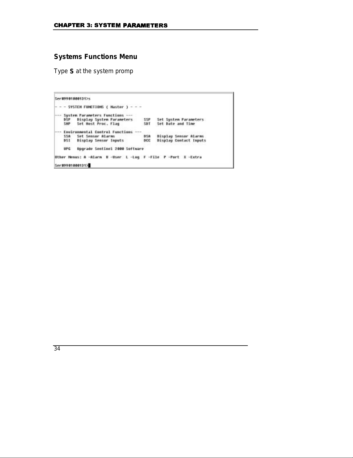
Systems Functions Menu
Type S at the system prompt and press the Enter key to display the
System Functions Menu.
The System Parameters Functions menu has three functional groups:
System Parameters Functions, Environmental Control Functions and
Upgrade Central Web Console software.
System Parameters Functions
The commands in this functional group enable you to set and
display system parameters including the host processing flag and
the date and time of the terminal server.
Environmental Control Functions
These functions are not supported in this version of the Central
Web Console.
34
Page 45
7(5
7(50
0,1
,1$
$/ 6(59(5 5
/ 6(59(5 5(
()(5
)(5(
Upgrade Terminal Server Software
The terminal server software, CCL interpreter and the flash
memory of the terminal server may be upgraded.
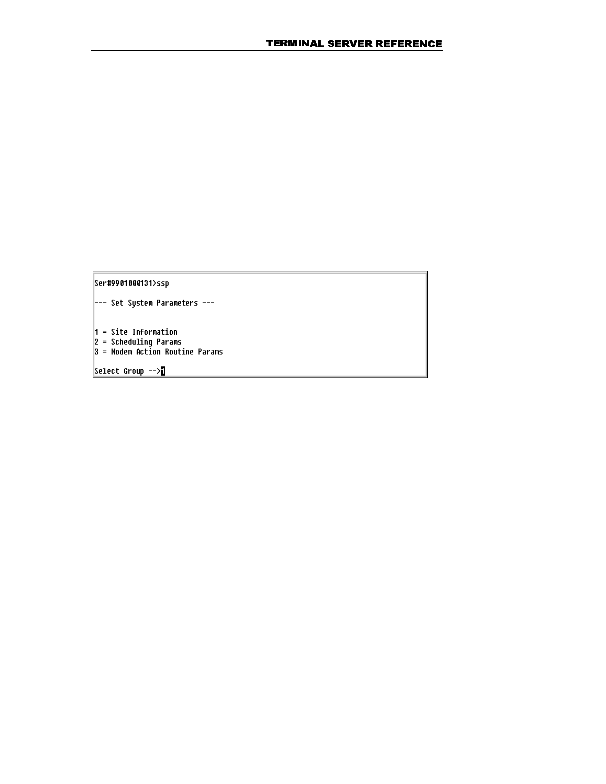
Set System Parameters – SSP Command
The Set System Parameters command enables you to set site
information, scheduling parameters and default telephone numbers.
(1&(
1&(
Type
to select which parameter group you want to be displayed.
SSP
The following screen appears. This chapter only covers the Site
Information parameters.
Site information
Type 1 to set Site Information. Site information includes site name,
terminal server phone number and the host password. The system
prompt displays the site name.
35
Page 46

&+$37(5
&+$37(5 6<67
6<67(
(0 3$5
0 3$5$
$0(7(
0(7(5
56
6
When the terminal server pages or phones in response to a particular
alarm or event, it sends its site name and unit phone number along with
the error message and other information that enables the receiver to
contact the correct terminal server.
Field Function
Site Name
(USN = Unit Ser. Number)
Descriptive name of the terminal server
location. When information is sent to
another device, the site name is included
automatically. The site name is displayed at
the prompt. The site name may have a
maximum of 30 alphanumeric characters.
Only the first 15 characters appear at the
prompt. The default site name is the unit’s
serial number. If you have more than one
terminal server at a site, using the serial
number as the site name is useful.
If a site name is not entered, only the
command prompt is displayed.
Unit Phone Number
36
Enter the phone number of the terminal
Page 47

7(5
7(50
0,1
,1$
$/ 6(59(5 5
/ 6(59(5 5(
server. This number is sent by the
PHONHOME Action Routine.
()(5
)(5(
(1&(
1&(
Host Password for login
routine
Number of Expansion Ports
Reassigned to Modems
Enter the password for the host system for
automatic login. The password may have a
maximum of 16 alphanumeric characters.
The terminal server has been configured to
use all expansion ports as host console
ports.
Upgrading the Software
Your Hewlett-Packard service representative notifies you when an
internal software upgrade is necessary. Installation instructions are
dependent on the type of upgrade required.
Specify Network Parameters
Communication with the terminal server occurs across a TCP/IP
network through either an Ethernet connection or a PPP link.
An Ethernet connection physically connects the terminal server to the
network. PPP (point-to-point protocol) allows a network connection to a
remote device via a modem connection. After a PPP link has been
established you can perform network functions, such as Telnet or FTP,
to the terminal server or to specific serial devices on the network. To
establish a PPP link or to initiate a Telnet session, you must have the
appropriate commercial software package installed and setup on the
remote PC. Connection to the network provides for the following
services:
Ping
•
Telnet communication
•
37
Page 48

&+$37(5
&+$37(5 6<67
•
•
6<67(
(0 3$5
0 3$5$
Network access to the terminal server for unit
•
administration
Net work access to the devices connected to the host
•
ports
Net work access to other devices on the network,
•
using the terminal server as a RAS
SNMP trap delivery
Deli very of SNMP traps for errors detected in the
•
terminal server
Deli very of SNMP traps for alarms conditions
•
detected in the devices connected to the host ports
FTP file delivery (Client)
Deli very of buffer files from the terminal server to a
•
network file server
$0(7(
0(7(5
56
6
Setting Network Parameters – SNP Command
If the terminal server is part of a network, it is necessary to set the
Network Initialization Parameters
the terminal server.
Parameters will only take effect if the
or by
restarting the terminal server
by either using the key switch on the front panel to power-cycle the unit
(off then back on – a ‘hard’ boot) or by issuing the
the command prompt to perform a ‘soft’ boot.
Each device on a network must have a unique Ethernet and IP address.
The Ethernet address of each terminal server is calculated by using a
registered OUI and the terminal server’s serial number. This ensures
that all terminal servers on the same network will have different Ethernet
addresses.
Before connecting the terminal server to your network, contact your
network administrator and obtain the following information:
38
Changes made to the Network Initialization
prior to starting the network module of
network has not yet been started
. You can restart the terminal server
BOOT
command from
,
Page 49

7(5
7(50
0,1
,1$
$/ 6(59(5 5
/ 6(59(5 5(
IP address to be assigned to the terminal server
•
IP address to be used for PPP connections
•
Subnet mask for the network segment to which the terminal
•
server will be connected
IP address of the default gateway to be used by the terminal
•
server
The terminal server allows a user to establish a PPP connection to the
internal modem. This connection allows a Telnet session to either the
terminal server or another device on the network attached to the
terminal server. In the latter case the terminal server acts as a dial-up
security server.
When a remote user attempts to access other network devices via a
PPP session, those devices must know how to direct their responses
back to the user. The simplest way to accomplish this is with a router
that supports RIP, the standard Router Information Protocol. The
strategy is to make the devices on the network direct their responses to
the router, and then have the router forward the data to the terminal
server. To do this, ensure that a RIP-enabled router is on the network,
and configure the other devices to use it as their default gateway. The
terminal server will automatically use RIP to tell the router how to
forward data addressed to the remote user when a PPP link is
established.
()(5
)(5(
(1&(
1&(
NOTE: The network number (the first set of numbers) for the PPP
connection in the terminal server should be different than the
network number used for the network IP address. If the network
address of the terminal server is 193.1.1.1 then the PPP address
should not begin with 193.
To set network parameters, type
the Enter key. Each prompt is explained in subsequent paragraphs.
39
at the system prompt and press
SNP
Page 50

&+$37(5
&+$37(5 6<67
6<67(
(0 3$5
0 3$5$
$0(7(
0(7(5
Network Initialization Parameters
56
6
The Network Initialization Parameters are set using the
command:
SNP 1
40
Page 51

7(5
7(50
Field Function
Restore Factory Defaults?
Initially No appears on the screen. Press
the space bar to toggle to Yes. Select Yes
to reload the values set at the factory.
0,1
,1$
$/ 6(59(5 5
/ 6(59(5 5(
()(5
)(5(
(1&(
1&(
--Network Initialization
Parameters--Start Network
on Power-up?
IP Address
(nnn.nnn.nnn.nnn)
PPP Address
(nnn.nnn.nnn.nnn)
Initially No appears on the screen. Press
the space bar to toggle to Yes. Yes will
start the network module on unit power-up
using the parameters defined with the SNP
command.
Enter the IP address of the terminal
server. Each device on the network must
have its own unique IP address. The IP
address assigned to the terminal server at
the factory may not be appropriate for your
network.
The IP address must be set before the
network module of the terminal server is
started. Once the network has been
started, changes to this parameter will take
effect only after the terminal server is
power-cycled (rebooted).
Enter the PPP address of the terminal
server. This is the IP address that is used
to identify the terminal server over a PPP
link. The network portion of the PPP
address must be different from the IP
address used above.
Subnet Mask
(nnn.nnn.nnn.nnn)
The subnet mask determines which part of
the terminal server's IP address represents
its network number and which part
represents its node number. Obtain an
appropriate value from your network
administrator.
41
Page 52

&+$37(5
&+$37(5 6<67
6<67(
(0 3$5
0 3$5$
$0(7(
0(7(5
56
Field Function
6
Default Gateway
(nnn.nnn.nnn.nnn)
The default gateway is the IP address of
the router or other equipment on the local
network segment that is used to direct
traffic to and from the segment. Obtain an
appropriate value from your network
administrator.
Enable RIP?
Initially Yes appears on the screen. Press
the space bar to toggle to No. Yes allows
the terminal server to direct routers on the
local network segment to use it as the
gateway to devices connected to the
terminal server via PPP.
Network-Loss Alarm Delay
Time
Enter a time in seconds, from 0 to 255. If
no network activity is detected for longer
than the specified amount of time, the
terminal server will generate a .NETDOWN
alarm.
Overview of SNMP Support by Terminal Servers
SNMP (Simple Network Management Protocol) is a TCP/IP protocol for
network management. It allows compliant devices to be configured
and/or to send error messages to Network Management software
packages.
The terminal server can send SNMP traps based on alarm conditions
detected in host devices or in the terminal server itself. Any alarm
condition that can be listed in the Action Table can be sent to a
management system via an SNMP Trap. Thus, the terminal server acts
as an SNMP trap proxy agent for devices that deliver alarms via
asynchronous RS-232 communication, via contact closures, or other
non-network mechanisms.
42
Page 53

7(5
7(50
0,1
,1$
$/ 6(59(5 5
/ 6(59(5 5(
()(5
)(5(
(1&(
1&(
MIBs
SNMP uses a data structure known as Management Information Base,
or MIB, to store information. Each piece of information, or object, in the
MIB has a unique Object Identifier. Object identifiers are indices based
on a tree structure. The information is held in a “node” at the end of a
“branch” in the tree. The Object Identifier shows the path by listing each
branch needed to reach the node.
The identifier serves to name or reference the object. MIBs for specific
companies are allocated to the MIB branch known as enterprise. Thus,
each company branches from the general branch known as enterprise.
From that point on in the MIB, the company developing the MIB controls
the information and Object Identifier used to reference the data. This
information is required to coordinate the sending and receiving of data
between an SNMP-compliant device and an SNMP-based network
management system.
When both the SNMP Agent and SNMP Management system have the
same MIB structure, data can be easily transferred and used. SNMP
data packets, each containing an object identifier and information
associated with that object, are passed between the device and
management system to populate the appropriate fields in the receiver’s
MIB. Both the Agent and Management System can then reference the
object and process the data as needed.
The terminal server has a general MIB as well as proprietary MIBs for
companies that use the terminal server as an SNMP trap proxy.
The following table shows the basic set-up of a MIB and provides
information about:
O bj ect Identif ier s – The index used to identify the information in the
•
MIB.
O bject Data – The information contained in the referenced data
•
node.
43
Page 54

&+$37(5
&+$37(5 6<67
O bj ect Source – The field in the terminal server where the
•
6<67(
(0 3$5
0 3$5$
$0(7(
0(7(5
56
6
information is located.
Object Identifier Object Data Object Source
1.3.6.4.1.1476.1.1.1 trapId Alarm Severity. Placed in the
Action Table Parameter Field.
The value can be from 1 to 10.
1.3.6.4.1.1476.1.1.2 trapSiteDesc Site name in System Parameter.
1.3.6.4.1.1476.1.1.3 trapSource SNMP Agent.
1.3.6.4.1.1476.1.1.4 trapDesc Alarm or error code. This is the
alarm as delivered by the host
device or terminal server
system. It includes all
parameters.
1.3.6.4.1.1476.1.1.5 trapComment Comment Field in Action Table.
The date and time of alarm are
also included in this field.
1.3.6.4.1.1476.1.1.6 trapExtraInfo Extra inform at ion associated
with this message. Assigned by
custom Action Routine.
1.3.6.4.1.1476.1.1.7 trapExpertData May contain up to 161
characters, and provides
additional data to the technician
that helps in the isolation or
correction of the problem.
An SNMP Management System can be configured to receive and use
SNMP traps sent by the terminal server by using the above information.
44
Page 55

7(5
7(50
0,1
,1$
$/ 6(59(5 5
/ 6(59(5 5(
()(5
)(5(
(1&(
1&(
NOTE: Configuration of the SNMP Management System may
require the assistance of your LAN Administrator. Please contact
him/her to determine how to compile the appropriate MIB for your
particular system.
Delivering SNMP Traps
The terminal server can send SNMP traps using one of the following
methods:
If t he Network Manager is on the same LAN or WAN as the terminal
•
server, the trap can be sent with the SNMPTRAP Action Routine
using the Ethernet connection.
If t he Network Manager is not on the same LAN or WAN, the
•
terminal server can establish a PPP link through a modem and
deliver the SNMP Trap.
SNMP Traps via Ethernet (Network)
Set all required network information using the SNP command. In the
Action Table, place an entry similar to the following:
Alarm Action Routine Parameter Comments
ERR123 SNMPTRAP 1 This is a major alarm
When the ERR123 alarm is detected, an SNMP trap is sent to the
management system(s) identified in the network parameters. All
information contained in the MIB is sent automatically. The parameter
for the SNMPTRAP routines sets the trap level (1-10). This parameter is
the enterprise specific trap ID and depends on the trap format (Nortel or
standard).
SNMP Traps via PPP
To denote that an SNMP trap is to be delivered via a PPP link, set the
appropriate field in the SNP command. When an SNMP trap is to be
45
Page 56

&+$37(5
&+$37(5 6<67
6<67(
(0 3$5
0 3$5$
$0(7(
0(7(5
56
6
delivered via a dial-up PPP link, the terminal server generates a
.PPPREQ event. Include entries similar to the following in your Action
table:
Alarm Action Routine Parameter Comments
ERR001 SNMPTRAP 2 This is a minor alarm.
.PPPREQ PHPPP 5551212 Create the PPP link.
The telephone number can be specified directly, or any of the default
telephone numbers specified in the system parameters can be
referenced. PHPPP is not compatible with firewalls or any security
measures on the remote access device.
Setting Terminal Server Parameters for SNMP Traps
The terminal server responds to “alarms” (such as an error condition on
a host) by performing an appropriate user-defined action. A typical
action might be connecting to a remote computer over a modem link
and sending error information from the host to that computer. SNMP
provides a standard way for the terminal server to report alarms to one
or more computers that are connected via network.
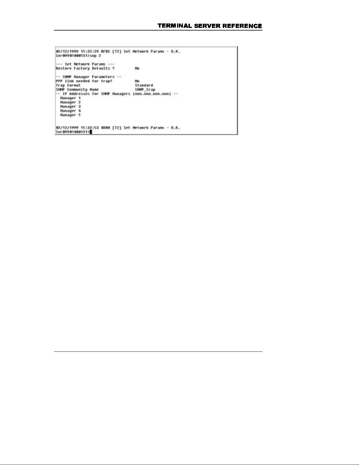
SNMP Manager Parameters
You can configure the terminal server to send a message, or “SNMP
trap,” to one or more supervisor computers, which are called SNMP
managers, in response to alarm conditions. These parameters are set
using the
46
SNP 2
command:
Page 57
7(5
7(50
0,1
Field Function
,1$
$/ 6(59(5 5
/ 6(59(5 5(
()(5
)(5(
(1&(
1&(
Restore Factory Defaults?
--SNMP Manager Parameters--
PPP link needed for trap?
Initially No appears on the screen.
Press the space bar to toggle to Yes.
Select Yes to reload the values set at
the factory.
If the terminal server is not connected
to the same network as its SNMP
Manager, it can reach the manager
over a modem link by using the
“Point-to-Point Protocol” (PPP) .
Initially No appears on the screen.
Press the space bar to toggle to Yes.
Set this option to Yes to establish a
modem link to
only one
SNMP
manager. Additional steps may be
necessary to configure the dial-out
process. Select No if the trap will be
sent via the network connection.
47
Page 58

&+$37(5
&+$37(5 6<67
6<67(
(0 3$5
0 3$5$
$0(7(
0(7(5
56
6
Field Function
Trap format
This option selects one of the active
MIBs to format the SNMP Trap. Two
formats are available: Standard and
Nortel. Press the
space bar
until the
desired choice is displayed.
SNMP Community Name
Enter the SNMP community name (up
to 20 characters can be used as a
name).
--IP Addresses for SNMP
Managers-
Manager 1
Manager 2
Manager 3
Manager 4
Manager 5
A maximum of five IP addresses can
be entered as SNMP Managers to
accept SNMP traps. If the IP address
is not on the terminal server’s network
segment, make sure the default
gateway is set and all routers have
been programmed with the proper
routes.
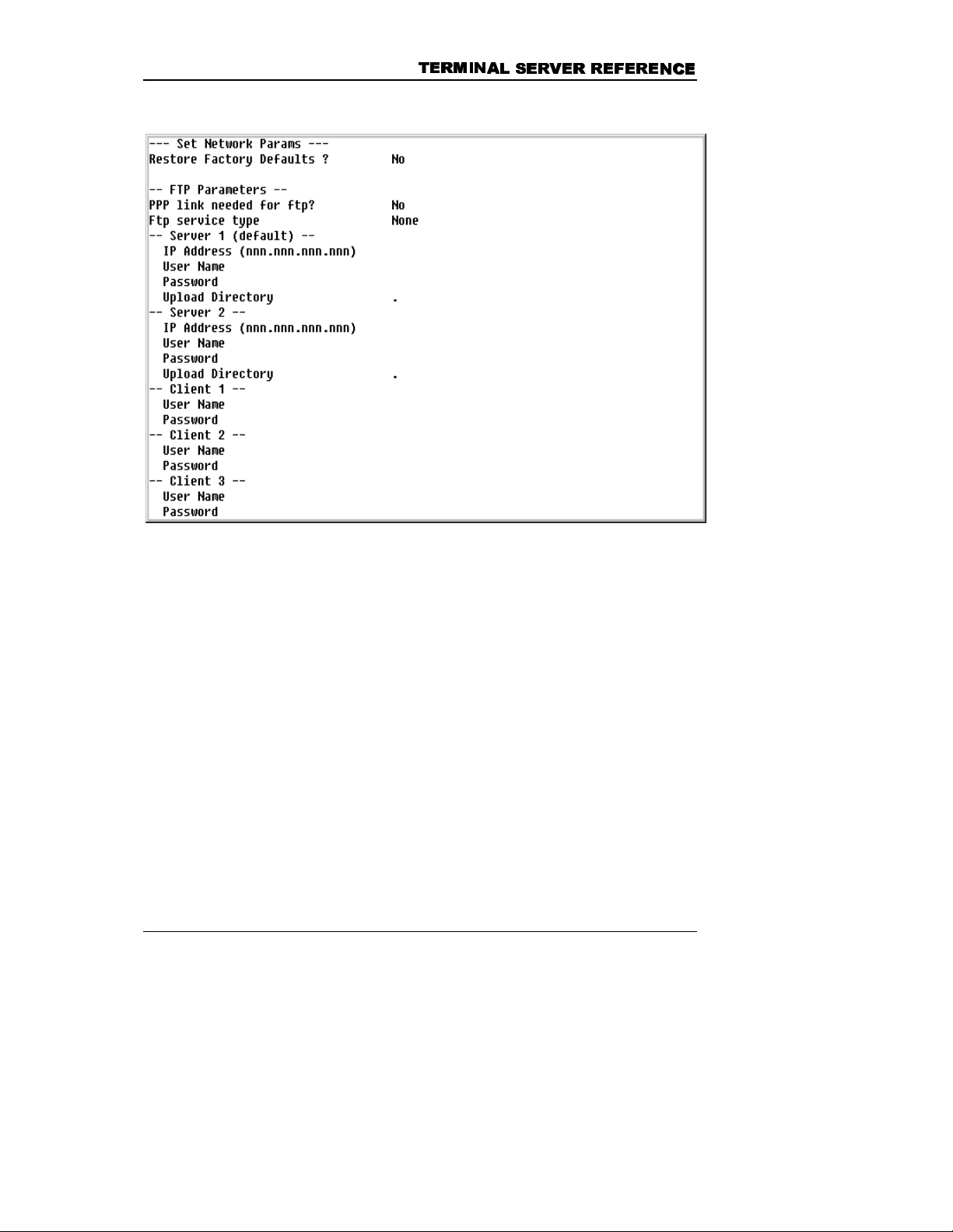
Setting FTP Parameters
The terminal server supports FTP Client Send commands. Files can be
sent from the terminal server to an FTP server using FTP (File Transfer
Protocol) protocol. To do this, you must set parameters in the Set
Network Parameters screen. After the parameters have been specified,
you may issue the SEBUF or SEND command with the appropriate
parameters.
To specify the FTP parameters, type
SNP 3
Parameters menu, FTP Parameters option.
48
to display the Network
Page 59
7(5
7(50
0,1
,1$
$/ 6(59(5 5
/ 6(59(5 5(
()(5
)(5(
(1&(
1&(
NOTE: In setting the user name and password, remember that they
are case-sensitive.
Field Function
Restore Factory Defaults
Press the space bar until the desired
choice is displayed. Select “Yes” to
restore original factory settings.
Select ‘No’ to keep the current
values.
PPP link needed for ftp?
Select this option if the terminal
server needs to dial out with a PPP
session to send files via FTP. (See
49
Page 60

&+$37(5
&+$37(5 6<67
6<67(
(0 3$5
0 3$5$
$0(7(
0(7(5
56
6
Field Function
the PPPREQ alarm and PHPPP
Action Routine in Chapter 8.)
FTP service type
Server 1 (default) –
IP address (nnn.nnn.nnn.nnn)
User name
Password
Upload directory
-- Server 2 - IP address (nnn.nnn.nnn.nnn)
User name
Select the type of FTP service (None
or Client Only). Press the space bar
until the desired choice is displayed.
Enter the IP address of the server.
The files transmitted by FTP are sent
to this address automatically unless
specified otherwise.
Enter the name used to log onto the
server. This entry is case-sensitive
Enter the password for the user
named above. This entry is case
sensitive.
Enter t he name of the directory t hat
should receive the file. A period
denotes the root directory.
Enter the IP address of the server.
The files transmitted by FTP are sent
to this address automatically when
server 2 is specified.
Password
50
Enter the name used to logon onto
the server. This entry is casesensitive
Enter the password for the user
named above. This entry is case
sensitive.
Page 61

7(5
7(50
0,1
Field Function
,1$
$/ 6(59(5 5
/ 6(59(5 5(
()(5
)(5(
(1&(
1&(
Upload directory
-- Client 1 - User name
Password
-- Client 2 - User name
Password
-- Client 3 - User name
Enter t he name of the directory t hat
should receive the file. A period
denotes the root directory.
Enter the name of the first u ser who
will log in as an ftp client. This entry
is case-sensitive
Enter the password for the user
named above. This entry is case
sensitive.
Enter the name of the second user
who will login as an ftp client. This
entry is case-sensitive
Enter the password for the user
named above. This entry is case
sensitive.
Enter the name of the third user who
will login as an ftp client. This entry
is case-sensitive
Password
Enter the password for the user
named above. This entry is case
sensitive.
The Terminal Sever can establish a PPP link after establishing a
SYSOP through a dialup (modem) connection. Set the parameters for
your terminal dial-up package according to the manufacturer’s
instructions and authenticate into the terminal server. At the system
51
Page 62

&+$37(5
&+$37(5 6<67
6<67(
(0 3$5
0 3$5$
$0(7(
0(7(5
56
6
prompt, type the command
and press enter. Send the terminal
PPP
server a “BREAK” from your terminal communication package and await
notification that a PPP link has been established. When co nformation
has been received, you may open up a telnet window and establish a
PPP link directly to the terminal server.
When connecting to a remote host via PPP, the are two standard
options of authentication: PAP (Password Authentication Protocol) and
CHAP (Challenge-Handshake Authentication Protocol). In the PAP
authentication process, the terminal server sends the username and the
password to the remote host. The remote host then determines whether
or not the user is allowed to establish the PPP link.
The CHAP option of authentication offers a higher-level of security since
the authentication process is encrypted. In this process, the terminal
server and the remote host have a shared secret key. The terminal
server transmits the local host name and the remote host responds with
a “challenge” number (random number). The “challenge” number is
then encrypted with a response back to the remote host, which encrypts
the challenge using the same secret key. If the responses match, the
PPP session is established.
Type
SNP 4
to display the Network Parameters menu, PPP Parameters
option.
52
Page 63
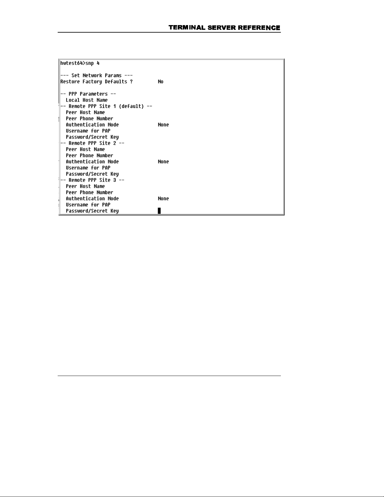
7(5
7(50
0,1
,1$
$/ 6(59(5 5
/ 6(59(5 5(
()(5
)(5(
(1&(
1&(
These parameters are set using the
SNP 4
command:
Field Function
Restore Factory
Defaults
Press the space bar until the desired choice
is displayed. Select “Yes” to restore original
factory settings. Select ‘No’ to keep the
current values.
Local Host Name
Remote PPP Site 1
Peer Host Name
Enter the host name to be used with the
CHAP authentication option.
Enter the name of the remote host which to
establish a PPP link.
53
Page 64

&+$37(5
&+$37(5 6<67
6<67(
(0 3$5
0 3$5$
$0(7(
0(7(5
Field Function
56
6
Peer Phone Number
Authentication Mode
Username for PAP
Password/Secret Key
Type
SNP 5
to display the Network Parameters menu, Telnet
Parameters option.
Enter the telephone number of the host to
which a PPP link will be established.
Press the spacebar to select the
authentication method to be used (PAP,
CHAP or None).
Enter the username for PAP authentication.
Enter the password, if PAP option has been
selected for authentication. Enter the secret
key, if CHAP has been selected for
authentication.
These parameters are set using the
Field Function
Restore Factory
Defaults
Press the space bar until the desired choice
is displayed. Select “Yes” to restore original
factory settings. Select ‘No’ to keep the
current values.
54
SNP 4
command:
Page 65

Field Function
7(5
7(50
0,1
,1$
$/ 6(59(5 5
/ 6(59(5 5(
()(5
)(5(
(1&(
1&(
Telnet service type?
Press the space bar until the desired choice
is displayed (None, Both, Client Only, Server
Only)
55
Page 66

&+$37(5
&+$37(5 6<67
6<67(
(0 3$5
0 3$5$
$0(7(
0(7(5
56
6
56
Page 67

7(5
7(50
0,1
,1$
$/ 6(59(5 5
/ 6(59(5 5(
()(5
)(5(
(1&(
1&(
4. FILE BUFFERING
What This Chapter Contains
The File Management Menu is organized into two sections: Disk/File
Maintenance Functions and Buffer Functions. The Disk/File Maintenance
Functions section lists the commands by which the user may edit or
manipulate files from the terminal server RAMdisk. The Buffer Functions
section lists commands for collecting data into files and for sending files
to the administration PC.
• Overview
• RAMdisk organization
• File naming conventions
• RA Mdisk protection parameters
• Saving and transfer ring data received by a host port
• Set t ing up automatic and manual buffering
• List of RAMdisk events
57
Page 68

&+$37(5
&+$37(5 )
),
,/(
/( %
%8)
8))
)(
(5
5,
,1
1*
*
File Management Menu
To view the File Management Menu, type F at the system prompt and
press the Enter key.
File Command Summary
Command Function
DIR Displays the files in the current directory. Directories are
indicated by <DIR> adjacent to the name, along with their
creation date and time.
MD Makes a new directory under the current directory.
MD <newdirectoryname>
Example: MD newdir
Creates a new directory named newdir under the current
directory.
58
Page 69

7(5
7(50
0,1
,1$
$/ 6(59(5 5
/ 6(59(5 5(
()(5
)(5(
(1&(
1&(
Command Function
CD Changes the current directory to a directory specified by
the user. Note that a space MUST follow this command.
Example: CD \ to return to the root directory.
CD .. to go up one level.
RD Removes the specified directory. An error is displayed if
the specified directory is not empty.
RD <directoryname>
Example: RD NEWDIR
COPY Copies the specified file to a specified location. The
destination directory must exist before the file can be
copied.
COPY <source directory>\<filename> <destination
directory>\<filename>
Examples:
COPY \sentfiles\H4961212.2A \newdir\H4961212.2A
To copy a file from the current directory to a new
directory
COPY H4961212.2A \newdir\H4961212.2A
DEL Deletes a file from the RAMdisk.
DEL <source directory>\<filename>
It is not necessary to specify the directory if the file to be
deleted is in the current directory.
Example:
DEL \sentfiles\H4961212.2A
59
Page 70

&+$37(5
&+$37(5 )
),
,/(
/( %
%8)
8))
)(
(5
5,
,1
1*
*
Command Function
MOVE Copies a file to a new directory and then deletes it from
the source directory after the file has been copied.
MOVE <source directory>\<filename> <destination
directory>\<filename>
Examples:
MOVE \sentfiles\H4961212.2A \newdir\H4961212.2A
To move a file from the current directory to a new
directory
MOVE H4961212.2A \newdir\H4961212.2A
RCV Command to receive files from the active port into the
current directory on the terminal server using XMODEM
or ASCII transfer. If FTP capability is available and the
FTP parameters have been set properly, RCV can also
be used to receive a file via FTP.
REN Renames the specified file
REN <filename> <new filename>
Example:
REN H4961212.2A DAYONE
The file H4961212.2A is renamed as DAYONE.
SEND Sends the specified file using either XMODEM or ASCII
transfer protocol. If FTP capability is available and the
FTP parameters have been set properly, SEND can also
be used to transmit a file via FTP.
VIEW Displa ys the contents of the specified file, one page at a
time. Scroll through the file by pressing <ENTER> to
view the next page. <CTRL-A> will return you to the
prompt.
60
Page 71

7(5
7(50
0,1
,1$
$/ 6(59(5 5
/ 6(59(5 5(
()(5
)(5(
RAMdisk Organization
There are 32 Mbytes available on the RAMdisk. You may create and
remove subdirectories, and copy, move, rename and delete files.
The directories listed below are automatically created by the system:
• A subdirectory is created for each host port that has buffering
enabled, 1MB maximum per port. The data collected from the
host port is stored in this subdirectory. The subdirectory is given
the same name as the host port by default. To view the host port
directory, type
number)
• T he \SENTFILES director y stores a copy of each file sent to the
administration PC. These files can be deleted automatically after
a preset number of days or when space available on RAMdisk
reaches a critical level.
• T he \LOGFILES directory contains files that are generated each
day by the terminal server to maintain a record of that day’s
activities. These files are of two types: Event files, which list the
alarms that were processed during one day, and Log files, which
contain a copy of one day’s log history.
OPBUF
h# (Where h# is the desired host port
at the system prompt.
(1&(
1&(
Host Port Buffer Naming
The user may change the default directory name for each host port. For
example, if Host port 1 is being used to monitor a Meridian switch, then
directory name may be changed to Meridian. See "Automatic Buffering"
for more information on changing the directory name.
Buffer File Naming Conventions
Filenames consist of capital letters and numbers and can have a
maximum of 12 characters. A period followed by a three-character
extension may be used provided the total number of characters does not
exceed 12.
61
Page 72

&+$37(5
&+$37(5 )
),
,/(
/( %
%8)
8))
)(
(5
5,
Examples: 101296AM.100
REPORT.01
IMPORTANTLOG
,1
1*
*
Note that in the screen above the default filename is
CURRENT.0.
current buffer file for a host port is always named either
CURRENT.1
. When the buffer is switched, the buffer file is renamed to
CURRENT.0
The
or
indicate the host port number from which the data was collected and the
date and time the buffer was opened.
Files collected via host port data by the terminal server are stored in the
directory of that host port and are assigned sequential names in order to
provide the user a means of identifying when and where the data in the
file was gathered. The terminal server uses following naming convention:
H
nyymmdd.hhq
Where: H = the letter H
= host port number [1-9, A-T represents ports 10-
n
28]
= year
yy
= month
mm
= day
dd
= hour
hh
= a letter (starting with ‘A’) used to differentiate
q
multiple files opened during the same hour.
62
Example 1: H2981218.14A
In this example, data is collected from host port 2 on the 18
th
day
of December (12) in 1998 (98) at 2-p.m. (14). The ‘A’ indicates
that this is the first file collected in that hour.
Example 2: HG980709.08D
In this example, data is collected from host port 16 (H), on the 9
th
day of July (07) in 1998 (98) at 8-a.m. (08). The ‘D’ indicates that
this is the fourth file collected in that hour.
Page 73

7(5
7(50
0,1
,1$
$/ 6(59(5 5
/ 6(59(5 5(
()(5
)(5(
(1&(
1&(
When a buffer is closed, the
CURRENT.x
file is renamed using the
convention described above, and left in the appropriate host port
subdirectory.
The Event and Log files that are generated by the terminal server have
names of the form listed below:
EVyymmdd.LOG (for Event files)
LGyymmdd.LOG (for Log files)
Where:E V = the letters E V
LG = the letters LG
yy = the last 2 digits of the year
mm = the month
dd = the day
.LOG = the letters .LOG
Setting the RAMdisk Protection Parameters
You should verify that the RAMdisk protection parameters are appropriate
for your application. The RAMdisk protection feature prevents the disk
from running out of room, which could result in the loss of data.
Monitoring of available space on the disk by the terminal server is done
continuously. You can configure the terminal server to delete files
automatically after a specified number of days or when the amount of
data on the RAMdisk reaches a preset critical level.
Files are not deleted automatically. If you do not specify a critical
percentage and the directories from which files are to be deleted, you will
have to monitor the disk and delete files when necessary. The terminal
server has default values, which may or may not fit your application.
Failure to raise the free space above the critical level causes a
“.DISKCRIT” event to be generated. The event .DISKCRIT can be
included in your Action Table along with the specified action to be taken.
63
Page 74

&+$37(5
&+$37(5 )
),
,/(
/( %
%8)
8))
)(
(5
5,
,1
1*
*
The RAMdisk protection parameters can be viewed by using the
(Display Disk Parameters) command or modified by using the
SDP
Disk Parameters) command.
Field Function
Keep SENT Files for how many
days?
Enter the number of days that files
in the /SENTFILES directory should
be kept. Files that have been sent
to the administration PC are
automatically moved to this
directory. Files that have been
closed for the specified number of
days old will be deleted at midnight.
The date of a file (date that the file
was closed) is the starting point.
DDP
(Set
Keep LOG Files for how many
days?
64
Enter the number of days that files
in the /LOGFILES directory should
be kept. System Log and Event
files are automatically placed in this
directory. Files that are the
specified number of days old will be
deleted at midnight. The date of a
file (date that the file was closed) is
the starting point.
Page 75

7(5
7(50
0,1
,1$
Field Function
$/ 6(59(5 5
/ 6(59(5 5(
()(5
)(5(
(1&(
1&(
Disk Critical Percent Free:
Directory Purge sequence While
Disk is Critical:
- SENTFILES
- LOGFILES
- sh
4
5
6
Purge Host When Critical
RAMdisk Events
Enter the percentage of disk space
that must be free. When this
percentage is reached, files will be
deleted in the order specified by the
entry for the
Directories to Purge
prompt.
Enter the names of the directories
that will be purged in sequence.
When disk space is critical, files will
be deleted from the first directory,
oldest files first, followed by the
second directory, etc. until disk
space is no longer critical.
Initially No appears on the screen.
Press the space bar to toggle to
Yes.
The terminal server, in response to certain RAMdisk conditions, will
generate events that are part of the standard software/firmware. These
standard events are as follows:
.BUFREADY A buffer file has been closed and is ready to be sent.
.DISKCRIT The RAMdisk has reached the critical level assigned in
the Set Disk Parameters screen.
.DISKFULL The RAMdisk is full and all further writes to the disk are
suspended.
65
Page 76

&+$37(5
&+$37(5 )
),
,/(
/( %
%8)
8))
)(
(5
5,
,1
1*
*
Buffering Data Received by a Host Port
The terminal server provides both automatic and manual control of data
buffering from the host ports. If automatic buffering is selected, a buffer
file for the specified port will be opened and data collected until either a
specified time or file size is reached. The current buffer file is then closed
and renamed using the format described in "Buffer File Naming
Conventions". A new buffer file is opened immediately.
Buffer switching occurs seamlessly, so that no data is lost during the
transition between files.
Automatic Buffering
When automatic buffering is enabled for a particular port, data is collected
in a buffer file for a preset length of time or until the file reaches a
specified size. To enable automatic buffering, enter the
command. ..
NOTE: To disable automatic buffering, use the CLBUF (close buffer)
command
.
(Set Host)
SH
66
Page 77

7(5
7(50
0,1
,1$
$/ 6(59(5 5
/ 6(59(5 5(
()(5
)(5(
(1&(
1&(
Field Function
Enable Automatic Buffering
Initially No appears on the screen.
Press the space bar to toggle to
Yes. Select Yes for automatic
buffering. Select No to disable it.
Compress closed buffer files?
Initially No appears on the screen.
Press the space bar to toggle to
Yes. Select Yes to compress buffer
files automatically when they are
closed.
The compression ratio is typically
4:1, but the ratio may vary because
67
Page 78

&+$37(5
&+$37(5 )
),
,/(
/( %
%8)
8))
)(
(5
5,
,1
1*
*
Field Function
it is dependent on the data.
Auto Switch (enter 0 to disable)
When CURRENT File exceeds
‘n’ K B
Enter the file size (in KB) at which
the buffer should be switched. Note
that the
CURRENT.x
file is renamed
using the convention described in
this section.
Enter 0 to disable this feature.
Every n hours
Enter the number of hours between
the switching of buffers.
Synchronize at what hour
(0-23)
Indicate the hour at which the buffer
should be switched. If the value is
set to 2 and the previous value is set
to 8, the buffer will switch at 200,
1000, and 1200 hours.
NOTE: If both the Current File exceeds ‘n’ KB and the Every n hours
parameters are set, the buffer is switched when the first condition is
met.
Manual Buffering
Buffers can be opened, closed and switched manually by the
Administrator. To do this, use the buffer commands listed in the File
Management Menu.
Command Function
OPBUF Open buffer
Opens a buffer for a port. You will be prompted
for the port number.
CLBUF Close buffer
Closes the buffer file for a particular port. You will
be prompted for the port number.
68
Page 79

Command Function
7(5
7(50
0,1
,1$
$/ 6(59(5 5
/ 6(59(5 5(
()(5
)(5(
(1&(
1&(
SWBUF
Switch buffer
Closes the buffer for the specified port and opens
a new one. You will be prompted for the port
number.
BST
Buffer status
Displays the status of all open and closed buffer
files for a specific host port.
OBST
Status of open buffers for each host port.
Displays the status of all open buffer files. Status
includes creation time, file size, and the time and
size at which the buffers will be switched (if
automatic buffering is enabled).
Using FTP to Send Files to an FTP Server
The terminal server supports FTP Client Send commands. Before you
can send a file via FTP, the following must have been done.
• A PPP link or Ethernet connection must be established.
• Parameters must be set in the Set Network Parameters
screen.
After specifying the parameters, you may issue the SEBUF or SEND
command with the appropriate parameters.
Files may be sent using FTP from the terminal server to another device
by issuing the SEND or SEBUF command. However, you must set the
FTP parameters prior to using these commands.
SEND transmits one file; SEBUF is used to send all buffer files from the
specified host port.
Notation used: As in ASCII and XMODEM protocols, the required
parameters are enclosed within angle brackets <>; optional
parameters are enclosed within square brackets [ ].
69
Page 80

&+$37(5
&+$37(5 )
),
,/(
/( %
%8)
8))
Command: SEND
)(
(5
5,
,1
1*
*
Syntax: SEND
Examples:
To send the file NEW.CFG to server #1 (the default
server entered using the
directory TEST while in the current directory, the
command format is:
Where:
<TEST> = name of the Host port Directory
<NEW.CFG> = name of file to send
F = use ft p protocol.
<serve r#> = N umber of t he server that will
<filename>,F,<server #>
(Uses the IP address, user name and
password for the specified server (1 or 2).
These parameters have been stored in the
FTP parameters screen.)
Files are sent from the current directory.
SNP 3
command) from the
SEND \TEST\NEW.CFG,F,1
receive the file, as listed in the
Network Parameters table.
70
To send a file from the current directory, you need not
enter a directory name:
SEND NEW.CFG,F,1
Files can also be sent to a server whose profile was not
entered into the terminal server with the
SNP 3
command. To do this enter the following information:
Page 81

7(5
7(50
0,1
,1$
$/ 6(59(5 5
/ 6(59(5 5(
()(5
)(5(
(1&(
1&(
SEND
<filename>,F,<IPaddr>,<user>,<password>,[directory]
Where:
<filename> = name of file to send.
F = use ftp protocol.
<IP addr> = IP address of the server that will
receive the file.
<user> = login name of the ftp user on the
server.
<password> = password of the ftp user on the
server.
[directory] = directory on the server into which
the file will be transferred. Enter the
directory or specify “.” to use the
current ftp directory.
Command: SEBUF
Description:
This command is used to send all closed buffer files in a
specific host port buffer directory to either server entered
with the SNP 3 command:
Syntax: SEBUF <host#>,F,<s erver#>
Where:
<host#> = is the number of the host port on the
terminal server
F = use ftp protocol.
<server#> = Number of the server that will receive the
file, as listed in the Network Parameters
table.
71
Page 82

&+$37(5
&+$37(5 )
Examples:
),
,/(
/( %
%8)
8))
)(
(5
5,
,1
1*
*
SEBUF
<host#>,F,<IPaddr>,<user>,<password>,[directory]
Where:
<host#> = is the number of the host port on the
terminal server
F = use ftp protocol.
<IP addr> = IP address of the server that will receive
the file.
<user> = login name of the ftp user on the server.
<password> = password of the ftp user on the server.
[directory] = directory on the server into which the file
will be transferred. Enter the directory or
specify “.” to use the default ftp directory.
To send all buffer files from Host port 1 using server
profile 2 and the FTP protocol, enter:
SEBUF 1,F,2
To send all buffer files from Host port 3 to a server at
address 193.1.1.241 with the username and password
of ftpuser, to the directory
recdir
enter:
SEBUF 3,F,193.1.1.241,ftpuser,ftpuser,\recdir
NOTE: Parameters are case-sensitive.
Using FTP to Receive Files from Another Device
The terminal server supports FTP Client Receive commands. Files can
be sent from the FTP server to a terminal server using FTP (File Transfer
Protocol) protocol. To do this, you must set parameters in the Set
72
Page 83

7(5
7(50
0,1
,1$
$/ 6(59(5 5
/ 6(59(5 5(
()(5
)(5(
(1&(
1&(
Network Parameters screen. After the parameters have been specified,
you may issue the RCV command with the appropriate parameters.
73
Page 84

&+$37(5
&+$37(5 )
),
,/(
/( %
%8)
8))
)(
(5
5,
,1
1*
*
74
Page 85

7(5
7(50
0,1
,1$
$/ 6(59(5 5
/ 6(59(5 5(
()(5
)(5(
(1&(
1&(
5. MODEM PORT SETUP
What This Chapter Contains
The parameters of the modem port specify the configuration of the port.
Modem port parameters must be set correctly in order for you to
successfully dial into the terminal server from a remote location and for
the terminal server to dial out.
Each unit is shipped with factory defaults for the modem(s) installed in the
terminal server. If you add or replace a modem with one of a different
make or model, you must check the modem port parameters to be sure
that they are set correctly for the installed modem. In particular, pay
special attention to the modem initialization string. An incorrect modem
initialization string can result in many problems. Consult the manual
supplied with the modem for detailed information.
• Overview
• How to Display and Set Modem Parameters
• Explanation of Each Par ameter
75
Page 86

&+$37(5
&+$37(5
0
02'(0
2'(0 3
3257
257 6
6(7
(78
83
3
Modem Port Parameters
Display Modem Port Parameters – DM Command
The DM (Display Modem port parameters) command enables you to view
the parameters of the specified modem port.
Type DM at the system prompt to display the modem port parameters.
You will be prompted to enter the number of the modem port whose
parameters you wish to view. The display will look similar to the one in the
SM parameters section. Each parameter is explained in the SM section.
76
Page 87

7(5
7(50
0,1
,1$
$/ 6(59(5 5
/ 6(59(5 5(
()(5
)(5(
(1&(
1&(
Set Modem Port Parameters – SM Command
The SM command enables you to display and change the parameters for
each modem port. Parameters include baud rate settings, parity, and
terminal emulation.
Type SM at the system prompt to display modem port parameters.
Field Function
Modem Number
Select the modem whose settings you wish
to change.
Restore Factory Defaults?
Initially No appears on the screen. Press the
space bar to toggle to Yes. Select Yes to
restore the factory settings. Select No to
keep the current settings. The factory default
settings are listed in the appendix.
Baud Rate Settings:
Modem Control Strings
The speed at which the terminal server
transmits data to the modem (internal or
77
Page 88

&+$37(5
&+$37(5
0
02'(0
2'(0 3
3257
257 6
6(7
(78
83
Field Function
external). An AT modem will not usually
establish a session with a remote modem at
a speed greater than the speed at which it
was set up. The actual speed of the user
session is a function of the type of
connection that is made between the remote
modem and the terminal server modem.
Press the space bar until the desired choice
is displayed. When the speed you want
appears in the field, press Enter key to select
that speed and advance to the next
parameter.
Available baud rates are 300,1200, 2500,
4800, 9600, 19200, 38400 and 57600.
3
User Session
The speed at which the terminal server
communicates with its modem.
When a connection is made to a remote
modem, the modems negotiate the
appropriate speed for the link. After the
speed has been determined, a message is
sent to the terminal server modem such as
"CONNECT 2400" or "CONNECT 9600".
Normally, the modem switches to the speed
in the message. Some modems, however,
(and most modems at some connect speeds)
do not indicate the speed with a CONNECT
message. In these instances, the speed
must be derived some other way.
Usually an Auto Baud routine is used to
sense the speed of the incoming data.
Sometimes it i s preferable to force the
incoming session at a particular speed.
CONNECT n sets the speed of the session
to the speed in the CONNECT message. If
78
Page 89

Field Function
CONNECT n is chosen, and no CONNECT
message is sent to the terminal server
modem, it reverts to Auto Baud.
Press the space bar until the desired choice
is displayed. When the speed you want
appears in the field, press the Enter key to
select that speed. Speeds available are
CONNECT n, 57600, 38400, 19200, 9600,
4800, 2400, 1200, 300 and Auto.
7(5
7(50
0,1
,1$
$/ 6(59(5 5
/ 6(59(5 5(
()(5
)(5(
(1&(
1&(
Char. Length/Parity
Terminal Emulation
Sysop Idle Timer
Use the space bar to select the character
length and parity characteristics of the
Modem Port. Available entries are 7 or 8
data bits, with Even, Odd, Mark, Space or no
parity.
The Auto entry initiates an auto-parity routine
with the user.
Specify the type of terminal that your
computer is emulating when your computer
is connected to the Modem Port via a remote
modem.
Press the space bar to toggle between TTY
and VT100.
If your computer is emulating a DEC VT-100
terminal, select VT100. If your computer is
not
emulating a DEC VT-100 terminal, select
TTY. After you make your selection, press
the Enter key.
NOTE: Only Sysop sessions are affected.
The Sysop idle timer defines the maximum
duration of inactivity time during a Sysop
session before the call is terminated and the
modem is reset.
79
Page 90

&+$37(5
&+$37(5
0
02'(0
2'(0 3
3257
257 6
6(7
(78
83
Field Function
Press the space bar until the desired choice
is displayed. When your choice appears in
the field, press Enter key to make your
selection.
Available selections are 1 min, 5 min, 10
min, 20 min and none.
3
Host Session Idle Timer
Host Session Disconnect
on Ctrl + A
Setup
The Host Session idle timer defines the
maximum duration of inactivity time during a
Host session before the call is terminated
and the modem is reset.
Press the space bar until the desired choice
is displayed. When your choice appears in
the field, press the Enter key to make your
selection and advance to the next parameter.
Available selections are 1 min, 5 min, 10
min, 20 min, none.
Initially Yes appears on the screen. Press
the space bar to toggle to No.
Defines the AT command string used to set
up the modem. You may edit this field,
depending on your modem requirements.
NOTE: The factory defaults shown on
page 5-2 are specific for the installed
modem. If the terminal server includes a
modem of a different make or model, a
different command string is required.
Consult the modem manual to determine
the appropriate command string.
Answer
80
Defines the AT Command string used to
answer calls. This should be either ATA
Page 91

Field Function
(answer immediately) or left blank. ATS0=n
(answer on the nth ring) can be included in
the setup initialization, however, the default
ATA is recommended.
7(5
7(50
0,1
,1$
$/ 6(59(5 5
/ 6(59(5 5(
()(5
)(5(
(1&(
1&(
Hangup
Dial Strings
Modem
Dial Strings
Pager
Defines the sequence for hanging up the line
~+++~AT|~ATS0=0 H0|
where
~+++~ escape sequence
ATS0=0 disables auto answer
ATH forces modem on-hook hang up
The command string used to initiate a dialout sequence with the modem. This is
typically used as part of a Callback
authentication process or to deliver an alarm.
Example:
ATDT ### |
The default phone number will be substituted
for the ### characters.
This command string specifies the dial string
used by the modem to deliver a message to
the pager.
Example:
ATDT ### @ MSG ; |
The default pager number from the System
Parameter table will be substituted for the
### characters and the default pager
message will be substituted for MSG. Press
Enter key to confirm your entry.
81
Page 92

&+$37(5
&+$37(5
0
02'(0
2'(0 3
3257
257 6
6(7
(78
83
3
NOTE: The | character represents a carriage return, and allows more
than one command to be entered on a single line as though it were
being entered on multiple lines. The ~ character forces a one
second delay. After editing the field, press Enter.
Verifying the Settings
To ensure that the settings are correct, do the following:
Dial int o the terminal server to verify that you can access it. Log on as
•
a Master user. If you cannot dial in, check the modem port settings.
Check t hat the terminal server can dial out. Add an Action Item
•
PHONHOME that is issued when a particular event is generated.
Generate the event by using the GE command. (See Chapter 1 for
more information on Action Tables and Action Items.) Have the
terminal server dial a PC running a terminal emulation program. If the
connection is successful, the date, time, site name, alarm and event
comment is displayed on the screen.
82
Page 93

7(5
7(50
0,1
,1$
$/ 6(59(5 5
/ 6(59(5 5(
6. TROUBLESHOOTING
What this Chapter Contains
Checking the Status of the LEDs
•
Det er mining Network Status
•
Q uer ying Remote Devices
•
Reboot t h e Terminal Ser ver
•
Reinit ializing the Terminal Server
•
Working with Configuration Files
•
CO NFIG Command Instructions
•
()(5
)(5(
(1&(
1&(
DUMPF Command Instructions
•
83
Page 94

&+$37(5
&+$37(5 7528
7528%
%/
/(
(6+
6+2
22
27
7,
,1
1*
*
Checking the Status of the LEDs
The following figure shows the status LEDs, all are visible from the front
of the terminal server.
The following table lists the terminal server LEDs and explains the state
or condition of the terminal server or its components when the LED is on
or off. In addition to the conditions listed in the OFF column, all of the
LEDs will be off when power to the terminal server is turned off.
LED Term. Server condition,
LED is on
AC (green) 16V DC supply unit is
operating.
48VDC
BATTERY
(green)
PWR FA IL
(red)
Not in use with this version
of the Central Web Console.
Internal battery is charging. Internal battery is charged.
Main power has failed;
internal battery is supplying
power to the unit.
84
Term. Server condition,
LED is off
Main power has failed;
internal battery is supplying
power to the unit. PWR FAIL
LED is on.
Main power supply unit is
operating.
Page 95

7(5
7(50
0,1
,1$
$/ 6(59(5 5
/ 6(59(5 5(
()(5
)(5(
(1&(
1&(
LED Term. Server condition,
LED is on
PULSE
(green)
ALARM PEND
(red)
CLR
(green)
EVENT PEND
(red)
CLR
(green)
FILE PEND
(red)
CLR
(green)
AUX RX/TX
(amber)
Flashes to indicate unit is
operating correctly.
Unit is processing an
alarm.
Normal operation. Unit is running internal
Unit queuing events
(alarms) for processing.
Normal operation. Unit is running internal
Data stored on RAMdisk
has reached the critical
level.
Normal operation.
Unit receiving or
transmitting data.
Term. Server condition,
LED is off
Unit is running internal
diagnostics (if AC or PWR
FAIL LED is on)
Normal condition.
diagnostics
Normal condition.
diagnostics
Normal condition.
Idle.
DTR
(amber)
HOST n RX/TX
(amber)
DTR
(amber)
MODEM 1 RX/T X
(amber)
CD
(amber)
Serial device is connected
to AUX port and DTR is
asserted.
Unit receiving or
transmitting data.
Serial device is connected
to Host port.
Unit receiving or
transmitting data.
Unit is connected to a
remote system.
Port is not active or no serial
device connected.
Idle.
Host port is not connected to
a serial device.
Idle.
Idle.
85
Page 96

&+$37(5
&+$37(5 7528
7528%
%/
/(
(6+
6+2
22
27
7,
,1
1*
*
LED Term. Server condition,
LED is on
ETHERNET RX
(amber)
TX
(amber)
Unit receiving data. Idle.
Unit transmitting data. Idle.
Term. Server condition,
LED is off
Determining Network Status
The
running, the following message appears:
The terminal server determines network status by detecting traffic on the
Ethernet link. The user sets the time interval for non-activity, which can
range from 1 to 255 seconds. Two alarms indicate network status: if
active the .NETUP alarm is issued, if inactive the .NETDOWN alarm is
issued.
command displays the status of the network. If the network is
DNS
An attempt at a Telnet connection into the terminal server results in no
response if the terminal server or network connection is down. A Sysop
session through the AUX port is the only way to restart or communicate
with the terminal server at this point.
NOTE: An Alarm/Event action routine must be created for these
alarms. Otherwise the unit will receive the alarm but will not know
what action to take.
To enter the time interval, type
SNP 1
at the prompt. At the Network-Loss
Alarm Delay Time, enter the time interval for non-activity on the network.
86
Page 97

7(5
7(50
0,1
,1$
$/ 6(59(5 5
/ 6(59(5 5(
()(5
)(5(
(1&(
1&(
An inactivity period longer than the Network-Loss Alarm Delay Time will
trigger the alarm .NETDOWN.
Querying Remote Nodes
The Port and Session Control Functions menu includes the
command. The
command is issued to query another device (IP
PING
PING
address) on a network.
Syntax: PING
<Ipaddr>.
Where <Ipaddr> is the IP address of the device
If successful, the reply shows the length of time it took to reach the
device. If the ping is unsuccessful, the message is “Device not
Reachable.”
Rebooting the Terminal Server
You can restart the terminal server by either using the key switch on the
front panel to power-cycle the unit (turn the key to Off then to On – "hard"
boot) or by issuing the
"soft" boot.
BOOT
command from the command prompt –
87
Page 98

&+$37(5
&+$37(5 7528
7528%
%/
/(
(6+
6+2
22
27
7,
,1
1*
*
Reinitializing the Terminal Server
Use a PC or terminal connected to the AUX port to re-initialize the
terminal server. The AUX port must be set at 9600 baud.
Note: This procedure requires that you re-establish your network
parameters and rebuild your user database.
1. Reboot the unit.
2. Watch the LEDs carefully. When the Pulse LED lights, wait
approximately one-half second and press Enter. The following System
LEDs will light: Alarm, Event, and File.
3. Type
initialization, type
, do not press Enter! You will be asked to confirm system re-
INIT
. Begin this step within 10 seconds of
YES
comple ting step 2.
4. Re-establish your networking parameters (IP and Ethernet, and FTP
addresses).
5. Download the HP.CFG and appropriate configuration files.
6. Configure the terminal server with the HP.CFG file and the
appropriate configuration file. See the next section for further
information about configuration files.
Working with Configuration Files
Each terminal server has a configuration file that specifies the parameters
of the terminal server and determines how the unit operates. This file
includes the Action Table, user Action Routines, System Parameters, and
Parameters of the AUX, Modem, Host Ports and Text Pager Messages.
Configuration files are created online or offline and are saved in ASCII file
format with the extension
parameters across multiple terminal servers. Configuration files can be
saved to a storage device, saved to the RAMdisk, or printed to a screen.
. One file can be used to replicate
*.cfg
88
Page 99

7(5
7(50
0,1
,1$
$/ 6(59(5 5
/ 6(59(5 5(
()(5
)(5(
(1&(
1&(
Note: Issuing the Upgrade command or re-initializing the terminal
server destroys all data stored to the RAMdisk.
Creating a Configuration File
Use an editing program such as Notepad or WordPad to edit or create
configuration files; these programs can read and write simple ASCII
formatted files. Word-processing programs such as Microsoft W ord are
not suitable for this function; they add formatting characters that destroy
the structure of a configur ation f ile.
Importing/Exporting a Configuration File
The File menu contains commands for transferring files between the
terminal server and a storage or editing device. In addition, the terminal
server supports two other commands: the DUMP command uploads a file
to the screen or a storage device, DUMPF downloads a file to the
RAMdisk.
CONFIG Command Instructions
Overview
A configuration file may be sent to the terminal server from a PC or to a
PC from the terminal server. The
configuration file, and the
DUMP
CONFIG
command exports configuration data to
a file. The CONFIG command allows a user to import a configuration into
an terminal server with a direct connect via the AUX port, over phone
lines, or via the network port.
1. Log onto the terminal server as a Master User.
2. Download the configuration file to the RAMdisk using XModem
transfer.
command imports a
89
Page 100

&+$37(5
&+$37(5 7528
7528%
%/
/(
(6+
6+2
22
27
7,
,1
1*
*
3. To configure the terminal server, type
system prompt and press Enter.
CONFIG
filename
at the
This section describes the different ways in which a terminal server’s
configuration can be “dumped” into a text file. The DUMP command
allows the user to view or backup the configuration of an terminal server
with a direct connection via the AUX port, over phone lines or via the
network port.
Procedure for Viewing Configuration Data at the Terminal Screen
1. Log onto the terminal server as a Master User.
2. Type
The banner
DUMP
and press the ENTER key.
Dump Configuration Details
appears, and a list of
system tables and system parameters displays. View one or more of
90
 Loading...