

Page 1

62108 1
HP Surestore Tape Library 20/700
A5605A Expansion Frame Installation Guide
(for HP field service use only)
CAUTION: The HP tape library Expans ion Frame is not custome r ins ta llable or
replaceable. Any servicing, adjustment, maintenance or repair must be performed only
by author iz ed HP service-trained personnel .
Note to Customer Engineer: This installat ion may add new techn ology to the lib rary
that older us er’s gu ides do not address. Plea s e remind the c ustomer t hat the latest us er
docume nta tio n is av ailable fro m th e H P C ustomer Ca re website: http://www.hp.com/go/
support.
■ Materials Included
■ Installation Notes
• Confirm with the customer System Administrator that the tape library can be powered
off.
• Observe proper power down and power on procedures, as described in the
Installation or Service Manual.
• If you install or replace an Expansion Module you must check mark the appropriate
box on the Drive Location Label. The Drive Location Label is located on the inside of
the library door, just below the UL label.
• Heavy Load. At least three people are required to remove the Expansion Frame from
packaging and push it into position.
Tools Required
Prior to beginning the installation process, obtain the following tools:
• 1/4-inch Ratchet Wrench
Table 1. Materials List
Part Quantity
I/I Expansion Frame 1
Expansion Frame Assembly 1
1/4-20 x 1/2-in. Torx Screws 6
Lock Down Latch Tool 1
Page 2
62108 2
■ Expansion Frame Install
1. Have the operator take the library and all drives offline and power off the tape library.
2. Obtain key and open cartridge area door.
CAUTION: Lifting ha za rd. Two people are required to rem ove the rear c ov er.
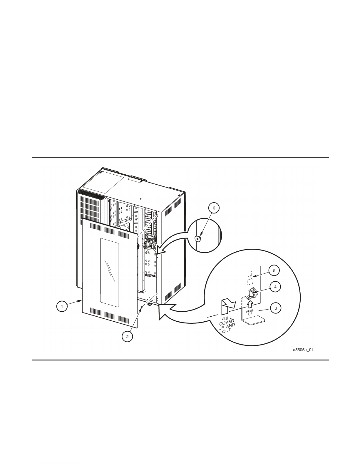
3. Remove the right rear cover (cover with window) by inserting the lock-down latch tool
(see “Special T ools”) between rear cover and the tape libra ry frame on the lower right- hand
side of cover to release cover lock-down latch (see Figure 1).
Figure 1. Removing Right Rear Cover
Page 3

62108 3
4. Slide cover up and set aside.
5. Using a T30 Torx driver, remove the mushrooms from the tape library frame (6 places) in
the area where the cover was removed (see Figure 1).
6. Position the robotic hand at the top of the Z-column and point it toward the drives.
CAUTION: Be careful not to hit your head on the theta lock down bracket
mounted to the top inside surface of the tape library frame.
7. Using a T15 Torx driver, remove the twelve No. 6-32 x 3/8-in. Torx Pan Head screws
holding the f ront left plate to the drive tower (see Figure 2) . Set the screws a nd plate aside.
8. If required, remove any customer data cartridges from the cells in Panel 2, Column 3 and
4. Be careful not to damage the cartridge s.
Note: The array labels appear directly above the arrays.
9. Remove the array retainer clip and the arrays from Panel 2, Column 3 and 4.
10. Reposition the robotic hand to point to Panel 2, Column 4 (where arrays were removed in
Step 7).
11. Remove theta stop closest to the dri ves using a flat blade screwdriver (see Figur e 2).
Removing Right Rear Cover (a5605a_01)
1. Rear Cover
2. Mushroom (6x)
3. Lock-Down Latch Tool
4. Lock-Down Latch
5. Mushroom (Ref)
6. Mushroom (Ref)
Figure 1. Removing Right Rear Cover (Continued)
Page 4

62108 4
Figure 2. Theta Stop and Mounting Holes
Theta Stop and Mounting Holes (a5605a_02)
1. Mounting Hole Locations
2. Remove Theta Stop
3. Mounting Hole Locations
4. Measure the distance from the floor to the inside floor of library
5. Front Left Plate
Page 5

62108 5
CAUTION: Heavy Load. At least three people are required to remove the Expansion
Frame from pac k aging and push it into po s it i on.
12. Remove the expansion frame from its package and place it flat on the floor.
13. Measure the distance from the floor of the room to the inside floor of the tape library (see
Figure 2).
14. Adjust the leveling bolts (4 places) on the expansion frame (measured from the inside
floor of expansion frame to the bottom of the leveling bolt) to be 1/16-inch to 1/8-inch
shorter than w hat was me as u red in St ep 13.
15. Stand the expansion frame up on the leveling bolts and position it against the frame of the
tape library. Be careful not to bend the leveling bolts when moving the expansion frame
into position.
16. To correctly align the expansion frame with the tape library:
• Align bottom locating pin in expansion frame to the hole in the tape library
floor.
• Align the top locating pin in the expansion frame to the top slot in the tape
library.
• Push the expansion frame firmly against the tape library frame (see Figure 3).
17. While holding the expansion frame in position, adjust the two leveling bolts closest to the
back until they touch the floor (s ee Figu re 3).
Page 6

62108 6
CAUTION: Be careful not to hit your head on the theta lock down bracket mounted to the
top inside su rf ac e of the tape libr ary f rame.
18. From the inside of the cartridge area, install six 1/4-20 x 1/2-in. long screws, using a T30
Torx driver, through the holes in the tape library frame into the expansion frame (see
Figure 2 for screw locations ) and tighten.
19. Using a T15 Torx driver, reinstall the plate to the left side of the drive using the 12 No.632 screws previously removed in Step 7.
Figure 3. Expansion Frame Alignment
Expansion Frame Alignment (a5605a_03)
1. Top Locating Pin
2. 1/4-20 x 1/2-in. Torx Screw (6x)
3. Expansion Frame
4. Leveling Bolt (4x)
5. Bottom Locating Pin
Page 7

62108 7
20. Replace the arra ys, the array retainer clips, and cartr idges removed in Step 7 back to Panel
2, Column 3 and 4.
21. Close the tape library doors and lock.
22. Power the tape library on and verify that it initializes and audits properly.
23. Return unit to customer.
Page 8

62108
REV C
EC 111700A
Copyright ©2002
Hewlett-Packard Company/
Storage Technology Corp
Edition 1/2002
 Loading...