

Page 1
Tape Library Twenty Slot to
Forty Slot Upgrade Kit
Modular Scalability Guide for Library Models
2/20, 4/40, 6/60, and 6/140
Edition 2
Part Number: C7242-90011
June 2000
Printed in Greeley, CO USA
Page 2

Notice
This document contains information that is protected by copyright. All
rights are reserved. No part of this document may be photocopied,
reproduced, or translated into another language. The information
contained in this document is subject to change without notice.
Printing History
New editions of this manual incorporate all material updated since the
previous edition. The manual printing date and part number indicate the
current edition. The printing date changes when a new edition is printed.
(Minor corrections and updates incorporated at reprint do not change
this date.)
Edition 1: January 2000: Initial printing.
Edition 2: June 2000: Added instructions for Library Model
6/140. See Chapter 4.
ii
Page 3

Typographical Conventions and Terms
WARNING Warnings call attention to a procedure or practice that could
result in personal injury if not correctly performed. Do not
proceed until you fully understand and meet the required
conditions.
CAUTION Cautions call attention to an operating procedure or practice that could
damage the product if not correctly performed. Do not proceed until you
understand and meet these required conditions.
NOTE Notes explain significant concepts or operating instructions.
TIP Tips provide hints or shortcuts for a procedure.
For the purpose of this documentation, we will use the term
“Model 6/140” to indicate all library models that are five levels and
higher. These models include: 4/100, 6/100, 6/120, and 6/140.
iii
Page 4

In This Manual
Chapter 1 Preparing a 20 or 40-Slot Library for the
Upgrade: Describes how to remove parts from
the existing library to accommodate the upgrade
module.
Chapter 2 Upgrading a 20-Slot Library to 40 or 60 Slots:
Describes how to upgrade libraries with the
capacity for two drives and twenty slots to a
library with the capacity for four drives and forty
slots or six drives and sixty slots.
Chapter 3 Upgrading a 40-Slot Library to 60 Slots:
Describes how to upgrade library modules with
the capacity for four drives and forty slots to a
library with the capacity for six drives and sixty
slots.
Chapter 4 Upgrading Library Model 6/140: Describes
how to upgrade the library by increasing its
capacity by twenty slots. The total capacity of
Model 6/140 is up to six drives and 140 slots.
iv
Page 5

Contents
1. Preparing a 2/20 and 4/40 Library for the Upgrade
2. Upgrading a 20-Slot Library to 40 or 60 Slots
Installation Overview. . . . . . . . . . . . . . . . . . . . . . . . . . . 1-2
Removing the Cosmetic Enclosure and Cover . . . . . . . 1-3
Removing the Cosmetic Doors . . . . . . . . . . . . . . . . . . . . 1-6
Removing the Front Panel Display . . . . . . . . . . . . . . . . 1-8
Preparing the Upgrade Module Chassis . . . . . . . . . . 1-10
Identifying Upgrade Kit Components . . . . . . . . . . . . . . 2-2
Upgrading 20-Slot Libraries to 40 Slots . . . . . . . . . . . . 2-5
Connecting the Library Modules. . . . . . . . . . . . . . . . . 2-11
Moving the Front Panel Components and Display. . . 2-18
Replacing the Display and Viewing Window . . . . . . 2-18
Replacing the Cosmetic Doors . . . . . . . . . . . . . . . . . 2-20
Verifying the Connection . . . . . . . . . . . . . . . . . . . . . . . 2-21
Powering on the Library . . . . . . . . . . . . . . . . . . . . . . 2-21
Running Diagnostic Tests . . . . . . . . . . . . . . . . . . . . . 2-21
Configuring the Library . . . . . . . . . . . . . . . . . . . . . . 2-22
Reconfiguring the Backup Software. . . . . . . . . . . . . 2-22
3. Upgrading a 40-Slot Library to 60 Slots
Identifying Upgrade Kit Components . . . . . . . . . . . . . . 3-2
Upgrading 40-Slot Libraries to 60 Slots . . . . . . . . . . . . 3-5
Connecting the Library Modules. . . . . . . . . . . . . . . . . . 3-8
Moving the Front Panel Components and Display. . . 3-13
Replacing the Display and Viewing Window . . . . . . 3-13
Replacing the Cosmetic Doors . . . . . . . . . . . . . . . . . 3-15
Verifying the Connection . . . . . . . . . . . . . . . . . . . . . . . 3-16
Powering on the Library . . . . . . . . . . . . . . . . . . . . . . 3-16
Running Diagnostic Tests . . . . . . . . . . . . . . . . . . . . . 3-16
Configuring the Library . . . . . . . . . . . . . . . . . . . . . . 3-17
Reconfiguring the Backup Software. . . . . . . . . . . . . 3-17
v
Page 6

4. Upgrading Library Model 6/140
Chapter Overview . . . . . . . . . . . . . . . . . . . . . . . . . . . . .4-2
Preparing the Existing Library for Upgrade. . . . . . . . .4-3
Removing the Side Panels. . . . . . . . . . . . . . . . . . . . . .4-3
Removing the Forehead, Top Cover, and Silver
Labels . . . . . . . . . . . . . . . . . . . . . . . . . . . . . . . . . . . .4-6
Preparing the Upgrade Module for Installation . . . . . .4-7
Check the Upgrade Kit Contents . . . . . . . . . . . . . . . .4-7
Preparing the Upgrade Module . . . . . . . . . . . . . . . . .4-9
Upgrading the 6/100 and 6/120 Model Libraries. . . . .4-10
Securing the Upgrade Module to the Cabinet . . . . . . . 4-11
Reassembling the Upgraded Library. . . . . . . . . . . . . . 4-15
Verifying the Connection . . . . . . . . . . . . . . . . . . . . . . . 4-18
Powering on the Library . . . . . . . . . . . . . . . . . . . . . .4-18
Running Diagnostic Tests . . . . . . . . . . . . . . . . . . . . .4-18
Configuring the Library . . . . . . . . . . . . . . . . . . . . . . 4-19
Reconfiguring the Backup Software . . . . . . . . . . . . . 4-19
vi
Page 7

Preparing for the Upgrade
1 Preparing a 2/20 and 4/40
Library for the Upgrade
Chapter 1 1-1
Page 8
Preparing a 2/20 and 4/40 Library for the Upgrade
Installation Overview
Installation Overview
IMPORTANT These procedures are only applicable for Library Models 2/20 and 4/40.
See Chapter 4 for information on upgrading a 6/140 library.
For this upgrade, you are adding additional library modules to increase
the library’s capacity by twenty slots and two drives per upgrade module.
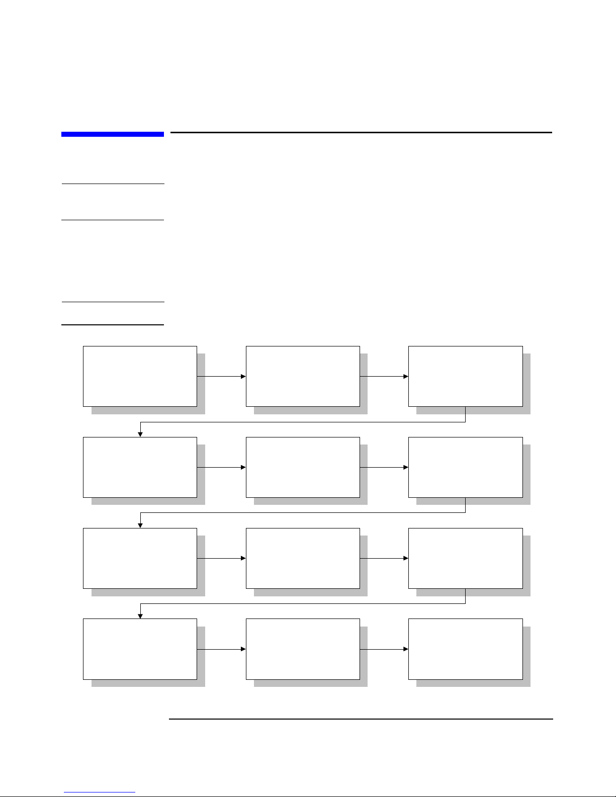
Though these procedures are described later in this guide, here is an
overview of the entire upgrade procedure:
NOTE This procedure should only be performed by a trained service technician.
Remove the top cover and
cosmetic enclosure on the
existing library.
For 20 to 40-slot
upgrades, add the vertical
lift assembly to the
transport assembly.
For 20 to 40-slot
upgrades, install the
vertical lift/transport
assembly into the top of
the chassis.
Move the display to the
top module. Replace the
front panel components.
Remove the front panel
components and display
from the existing library.
Stack the upgrade module
on top of the existing
library.
Install the interconnect
cable between the
motherboards on both
modules.
Connect the power cord
and power on the library.
Remove the silver label
from the top of the existing
library.
Secure the two modules
together with screws.
Add the upgrade notice
label to the back of the
library and under the front
magazine on the lowest
module.
Verify the connection and
run diagnostic tests.
Chapter 11-2
Page 9

Preparing a 2/20 and 4/40 Library for the Upgrade
Removing the Cosmetic Enclosure and Cover
Removing the Cosmetic Enclosure and Cover
This chapter describes the disassembly procedures needed to prepare the
existing 2/20 and 4/40 library for this upgrade. If your library is
rackmounted and you are upgrading a twenty-slot library to forty slots,
you will need 6 EIA of clearance (10.5 inches) above the existing library
to accommodate the upgrade module. For a forty to sixty-slot upgrade,
you will need 5 EIA of clearance (8.75 inches) above the existing library.
CAUTION This library contains very sensitive electrical components. It is important
to follow the proper procedures for preventing electrostatic discharge
(ESD). Use wrist-grounding straps and anti-static mats when removing
and replacing cards and major assemblies.
Preparing for the Upgrade
Failure to follow proper procedures could damage the circuitry.
WARNING For rackmounted upgrades, extend the rack’s anti-tip foot and
lower the leveler feet. Failure to extend the anti-tip foot could
result in personal injury or damage to the tape library if the rack
tips over.
Chapter 1 1-3
Page 10

Preparing a 2/20 and 4/40 Library for the Upgrade
Removing the Cosmetic Enclosure and Cover
Remove the cosmetic enclosure, cover, and label by following these steps:
1. Power off and unplug the library.
2. For a standalone library, remove the cosmetic enclosure. Refer to
Figure 1-1 for the screw locations. You will not reuse this enclosure
after the upgrade.
Figure 1-1 Removing the Cosmetic Standalone Enclosure
Chapter 11-4
Page 11
Preparing a 2/20 and 4/40 Library for the Upgrade
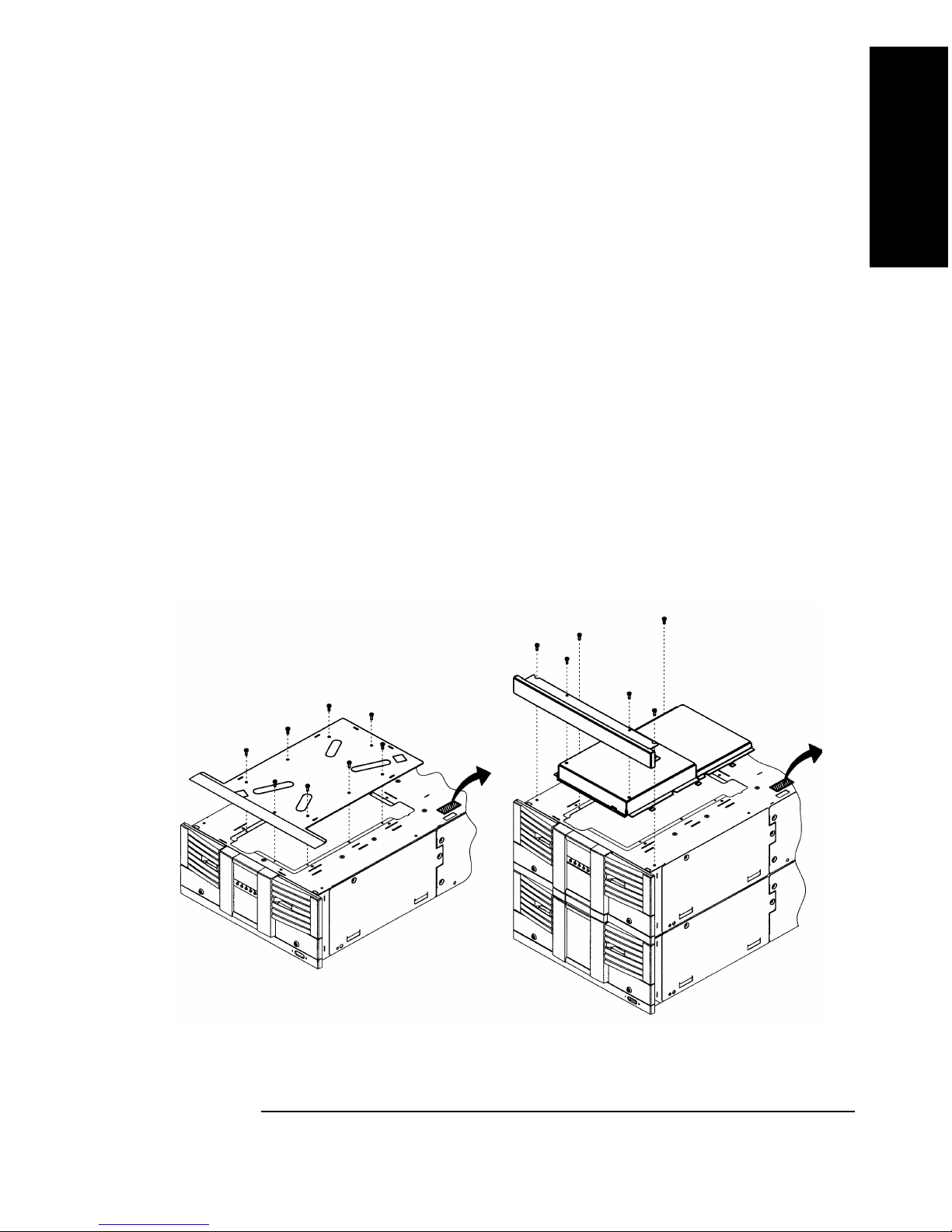
Removing the Cosmetic Enclosure and Cover
Remove the top cover from the existing library. Save these screws to
reinstall the vertical lift top cover after the upgrade. Refer to
Figure 1-2 for the screw locations.
• For 40 to 60-slot rackmounted upgrades, you will need to remove
the stop latch bracket to remove the vertical lift cover. See
Figure 2-10 on page 2-14.
• For libraries rackmounted in a 55-mm bezel depth rack, remove
the trim brackets from each side of the library (see Figure 2-11 on
page 2-15 or Figure 3-6 on page 3-10 for the location of the trim
bracket screws). The trim brackets secure the library to the rack.
• Push the library 2/3 of the way out of the rack by using the vertical
handle at the back of the library. Do not push the library past the
stop bracket.
Preparing for the Upgrade
3. Remove the silver label on top of the library chassis (Figure 1-2). Yo u
must remove this label to connect the library modules together.
Figure 1-2 Removing the Cover
Chapter 1 1-5
Page 12

Preparing a 2/20 and 4/40 Library for the Upgrade
Removing the Cosmetic Doors
Removing the Cosmetic Doors
NOTE Depending on your library model and configuration, the cosmetic doors
might look different from the illustrations.
1. Pull the front door outward. Use the key, if necessary, to unlock the
door.
2. Remove the front magazine by lifting the handle on the top of the
magazine and pulling upward (Figure 1-3 on page 1-7). Make a note of
where the magazines are located so that you reinstall them in the same
place.
3. Push the release tab on the back of the cosmetic door and
simultaneously pull upward on the sheet-metal tab to release the
door (see Figure 1-3 on page 1-7).
CAUTION To avoid breaking the tab, do not use excessive force.
4. Remove the remaining cosmetic doors by following the steps above.
Chapter 11-6
Page 13

Figure 1-3 Removing the Cosmetic Doors
Preparing for the Upgrade
Preparing a 2/20 and 4/40 Library for the Upgrade
Removing the Cosmetic Doors
1 Release tab
2 Sheet-metal tab
3 Cosmetic door connecting hooks
Chapter 1 1-7
Page 14

Preparing a 2/20 and 4/40 Library for the Upgrade
Removing the Front Panel Display
Removing the Front Panel Display
CAUTION This library contains very sensitive electrical components. Follow the
proper procedures for preventing electrostatic discharge (ESD). Use
wrist-grounding straps and anti-static mats when removing and
replacing cards and assemblies.
Failure to follow proper procedures could damage the circuitry.
1. Remove the display cover and chin plate underneath the display on
the existing library module. The screw locations are indicated in
Figure 1-4. Save these screws to later reinstall the display cover and
chin plate.
NOTE Your library might only be one module instead of two modules, which is
shown in Figure 1-4.
2. Remove the display cover by lifting it upward and away from the
library.
Figure 1-4 Removing the Chin Plate and Front Cover
Chapter 11-8
Page 15

Preparing a 2/20 and 4/40 Library for the Upgrade
Removing the Front Panel Display
3. Remove the two screws that connect the display to the chassis
(Figure 1-5). Save these screws to later reconnect the display.
Figure 1-5 Removing the Front Panel Display and RFI Shield
Preparing for the Upgrade
4. Remove the front panel display by sliding it upward, then gently
lifting it away from the front of the library.
5. Disconnect the cable from the back of the display by grasping the
sides of the connector and pulling outward. Place the front panel in
an ESD-protected area.
CAUTION Ensure the display cable is not obstructing the internal moving parts.
Secure the cable to the side of the chassis.
6. Remove the black RFI display shield, which is located behind the
display (Figure 1-5). Two screws secure the sheet-metal shield to the
library chassis.
Chapter 1 1-9
Page 16

Preparing a 2/20 and 4/40 Library for the Upgrade
Preparing the Upgrade Module Chassis
Preparing the Upgrade Module Chassis
In addition to preparing the existing library for the upgrade, you will
also need to modify the upgrade module chassis to optimize the upgrade
procedure.
• Unpack the chassis from the upgrade kit.
From the front of the upgrade module, remove the black sheet-metal
RFI shield. See Figure 1-5 on page 1-9 for the location and
instructions on removing this part. Save these screws to later reinstall the shield.
• On the 20 to 40-slot upgrade, remove the top cover from the upgrade
module. See Figure 1-2 on page 1-5 for the location and instructions
on removing the top cover.
Chapter 11-10
Page 17

Upgrading 20-Slot Libraries
2 Upgrading a 20-Slot Library to
40 or 60 Slots
Chapter 2 2-1
Page 18

Upgrading a 20-Slot Library to 40 or 60 Slots
Identifying Upgrade Kit Components
Identifying Upgrade Kit Components
See Chapter 3 for more information on Model 4/40 and Chapter 4 for
more information on Model 6/140.
NOTE If you are upgrading a 20-slot library to a 60-slot library, you will use the
following upgrade kit, as well as the upgrade kit described on Table 3-1
on page 3-2.
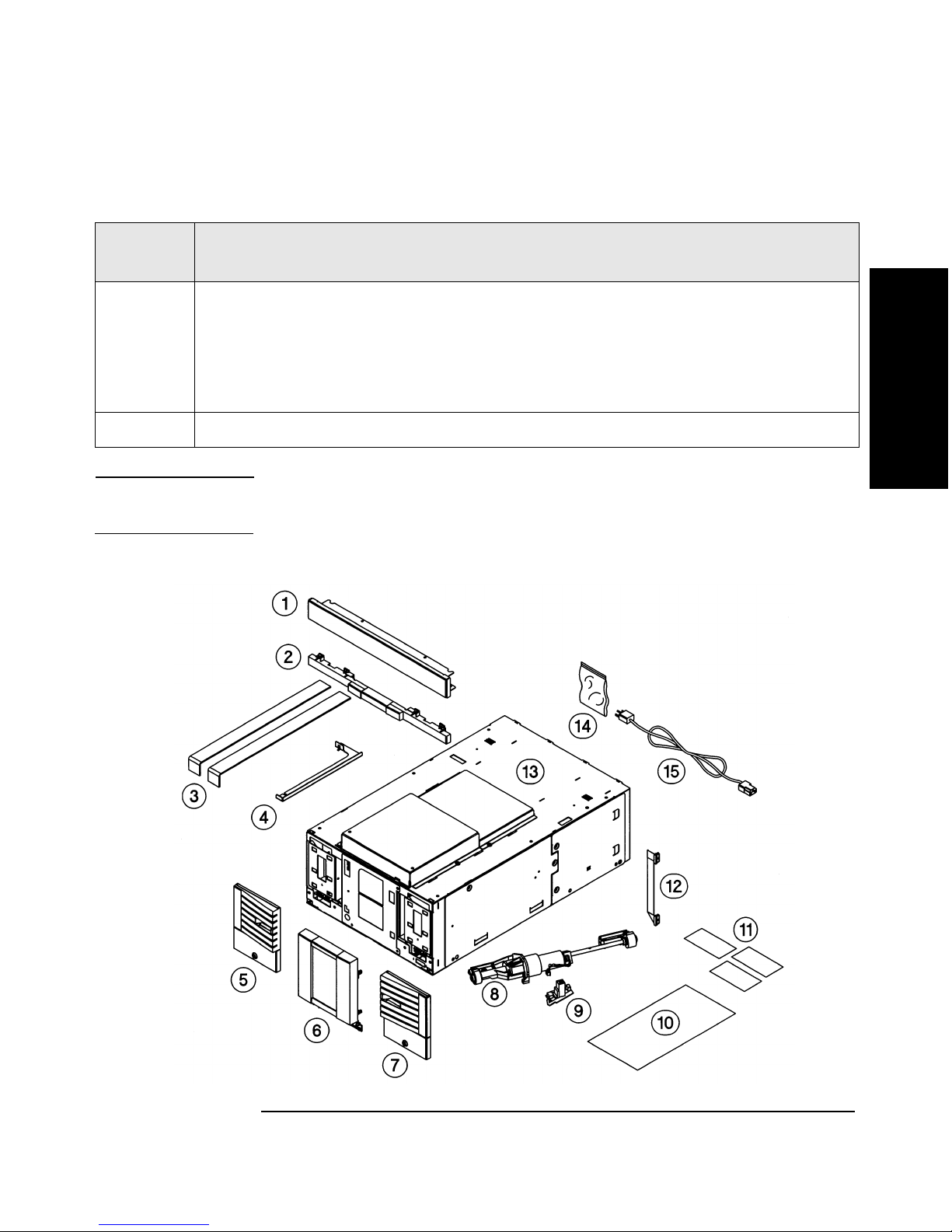
Table 2-1 Upgrade Kit Contents (Depending on Configuration)
Callout
Number
1 Forehead
2Chin plate
3 Plastic slider tools
4 Stop latch bracket
5 Cosmetic door with sheet-metal tabs
6 Viewing window
7 Cosmetic door with sheet-metal tabs
8 Vertical lift assembly
9 Vertical lift circuit board
10 Clip nut template for rackmounted upgrades
11 Upgrade labels
12 Interconnect cable
Description of Part
13 Library chassis that includes a top cover, slave controller card, power supply,
and magazines
Chapter 22-2
Page 19
Upgrading a 20-Slot Library to 40 or 60 Slots
Identifying Upgrade Kit Components
Table 2-1 Upgrade Kit Contents (Depending on Configuration)
Callout
Description of Part
Number
14 Hardware bag that contains the following (extra parts provided):
• Clip nuts
• 10-24 x 0.50 Screws
• 6-32 Phillips
15 Power cord
NOTE The drive, fibre channel card, and cosmetic enclosures are separate
upgrade kits.
Figure 2-1 Exploded View of Upgrade Kit Components
Upgrading 20-Slot Libraries
Chapter 2 2-3
Page 20

Upgrading a 20-Slot Library to 40 or 60 Slots
Identifying Upgrade Kit Components
During the upgrade, you will not reuse the following parts:
Parts to Discard
Top cover for 20-slot libraries (Figure 1-2 on page 1-5)
Guide blocks on top of the transport assembly (Figure 2-3 on
page 2-6)
Existing cosmetic enclosure for standalone libraries (Figure
1-1 on page 1-4)
Plastic slider tools from the upgrade kit (Figure 2-4 on page 2-
8)
Existing trim brackets for libraries rackmounted with 55-mm
bezel depth (Figure 2-11 on page 2-15)
Stop bracket for 20-slot libraries
CAUTION This library contains very sensitive electrical components. It is important
to follow the proper procedures for preventing electrostatic discharge
(ESD). Use wrist-grounding straps and anti-static mats when removing
and replacing cards and major assemblies. Failure to follow proper
procedures could damage the circuitry.
Chapter 22-4
Page 21
Upgrading a 20-Slot Library to 40 or 60 Slots
Upgrading 20-Slot Libraries to 40 Slots
Upgrading 20-Slot Libraries to 40 Slots
NOTE This procedures assumes you are upgrading the library while it is in a
rack. If you are upgrading a standalone library, follow the same
procedure, disregarding the rackmount steps.
WARNING Before you begin, extend the rack’s anti-tip foot and lower the
rack’s leveler feet. Failure to extend the anti-tip foot could result
in personal injury or damage to the tape library if the rack tips
over.
1. Complete the steps in Chapter 1.
2. For rackmounted libraries, ensure the library is in the service
position (approximately 2/3 of the way out of the rack).
Upgrading 20-Slot Libraries
3. Using the finger holes, lift the transport assembly up and out of the
library. Place the transport nearby, disconnecting the umbilical cable
from the library chassis by pulling the tabs outward (Figure 2-2).
Gently fold the cable underneath the transport assembly.
Figure 2-2 Removing the Transport Assembly
Chapter 2 2-5
Page 22

Upgrading a 20-Slot Library to 40 or 60 Slots
Upgrading 20-Slot Libraries to 40 Slots
4. Install the vertical lift assembly to the transport assembly by
following the steps below (see Figure 2-3):
a. Remove the guide blocks from the top of the transport assembly.
Three screws secure each guide block to the top of the transport
assembly. Save these screws to install the vertical lift assembly in
step 4c.
b. Align the lift circuit board with the screw holes on the transport
assembly, and insert two screws. The screws and board are
packaged together in the upgrade kit. Tighten the screws securely,
but do not over-tighten.
c. Align the screw holes in the vertical lift assembly to the top of the
transport assembly. Insert five of the screws from step 4a, and
tighten in the order specified in Figure 2-3.
d. Connect the vertical lift and motor power cable. Do not re-install
the vertical lift/transport assembly into the library at this time.
Figure 2-3 Installing the Vertical Lift Assembly onto the Transport
Chapter 22-6
Page 23

Upgrading a 20-Slot Library to 40 or 60 Slots
Upgrading 20-Slot Libraries to 40 Slots
5. If your rack does not have threaded screw holes, select the 4/40 or 6/60
clip nut template, which matches the height of the upgraded library,
and follow the steps below:
a. Hold the template next to the rack column so that the bottom of
the template aligns with the bottom of the library.
b. Install three clip nuts from the upgrade kit into each front column
of the rack. The top two clip nuts are used for the top mounting
rail. The middle clip nut is used for the trim bracket. For racks
with a 55-mm bezel depth, you can remove the original trim
brackets and push the library flush into the rack to install the
bottom clip nuts.
c. Using the rackmount template, install two clip nuts into each back
column of the rack.
NOTE Use the EIA markers as a reference point to ensure the holes on the rack
correspond to the holes on the template. The EIA markers on the
templates are represented by #>.
Upgrading 20-Slot Libraries
6. Pull the existing library into the rack using the vertical handle on the
back of the library.
7. Remove the top mounting rails (one on each rack column) to allow the
upgrade unit to slide on top of the library.
a. Remove the screws in the front and back that attach the top rails
to the column, and lift each rail up and out of the rack.
b. Save these screws to reinstall the mounting rails.
Chapter 2 2-7
Page 24

Upgrading a 20-Slot Library to 40 or 60 Slots
Upgrading 20-Slot Libraries to 40 Slots
8. Place the plastic slider tools on top and at the front of the existing
library (see Figure 2-4).
Figure 2-4 Installing the Plastic Slider Tools
Chapter 22-8
Page 25

Upgrading a 20-Slot Library to 40 or 60 Slots
Upgrading 20-Slot Libraries to 40 Slots
9. Remove the stop bracket from the back of the library module. You will
not reuse this stop bracket.
WARNING To avoid personal injury or damage to the library, do not pull the
library out of the rack once the stop bracket and top mounting
rails are removed. The library is not secured inside the rack until
you reinstall the stop bracket for the upgrade module.
Figure 2-5 Removing the Stop Bracket
Upgrading 20-Slot Libraries
10.Using two people or an appropriately rated mechanical lift, align the
bottom of the upgrade module with the top of the existing library.
(The upgrade module weighs 47 pounds.) Do not lift the library using
the power supply or drive module handles.
11. Slide the upgrade module on top of the library until the modules are
aligned in the front. Remove the plastic slider tools.
12.Finish aligning the two modules together by gently moving the top
unit side-to-side until it clicks into place. Ensure the modules are
connected by moving to the back of the library and moving the top
unit side-to-side until it also clicks into place.
Chapter 2 2-9
Page 26

Upgrading a 20-Slot Library to 40 or 60 Slots
Upgrading 20-Slot Libraries to 40 Slots
13.Re-install the top mounting rails by following the steps below:
a. Ensure the rails are fully extended to the outside of the rack
column and install them on top of the library. Ensure you are
using the correct top mounting rail holes (see Figure 2-6).
b. Lower the rails to the top of the library and rotate them out until
they drop between the rack column and the library. Be careful not
to accidentally move the clip nuts.
c. Attach the rails to the front of the rack. Use the same screws that
originally attached the rails to the rack.
d. Ensure the rails are extended to the outside of the rack column,
and attach the rails to the back of the rack.
NOTE Ensure the mounting rails are installed in the same location in the front
and back of the rack. The rails should be level with the top of the library.
Figure 2-6 Mounting Rail Location
Chapter 22-10
Page 27

Connecting the Library Modules
1. Secure the two units together by installing one 10-24 x 0.50 screw
from the upgrade kit behind each cosmetic door (Figure 2-7). You will
need to remove the magazines and use a short T-25 driver to access
these screw holes.
2. Push the library out of the rack, using the lowest library module.
Continue easing the library out of the rack until the library is 2/3 of
the way out of the rack. Do not push the library past the stop bracket.
3. Install seven 10-24 x 0.50 screws inside the chassis to secure the two
units together (Figure 2-7).
Figure 2-7 Installing the Screws
Upgrading a 20-Slot Library to 40 or 60 Slots
Connecting the Library Modules
Upgrading 20-Slot Libraries
Chapter 2 2-11
Page 28

Upgrading a 20-Slot Library to 40 or 60 Slots
Connecting the Library Modules
4. Install the vertical lift/transport assembly into the chassis by
following the steps below:
a. Connect the umbilical cable to the lowest library chassis, ensuring
the cable is not pinched. You might need to partially remove the
drives on the lowest library module to access the umbilical cable
connector (Figure 2-2 on page 2-5).
b. Ensure the gear teeth on the vertical lift/transport assembly are
aligned with the gear rails and that the gear rails are level with
each other (see Figure 2-8).
c. When the vertical lift/transport assembly is level with the top of
the upgraded library, lower it to the bottom of the library.
Figure 2-8 Aligning the Gears
A Gears incorrectly aligned 1 Gears
B Gear correctly aligned 2 Gear rails (racks)
3 Check points to ensure
alignment
Chapter 22-12
Page 29

5. Install the top (vertical lift) cover on the library using two 10-24 x
0.50 screws on one side of the library and the connecting tabs on the
other side (Figure 2-9). You can wait to install the back left screw
until you complete step 6.
a. Install the forehead included in the upgrade kit with four 10-24 x
0.50 screws.
b. Install the weight warning label on the top cover.
c. For standalone libraries, install the cosmetic enclosure (see Figure
1-1 on page 1-4 for screw locations).
Figure 2-9 Installing the Cover and Forehead
Upgrading a 20-Slot Library to 40 or 60 Slots
Connecting the Library Modules
Upgrading 20-Slot Libraries
Chapter 2 2-13
Page 30

Upgrading a 20-Slot Library to 40 or 60 Slots
Connecting the Library Modules
6. Install the stop latch bracket on top of the library by following these
steps (see Figure 2-10):
a. Remove, if necessary, the left screw from the top cover.
b. Install the stop latch bracket by inserting the tab into the latch
stop.
c. Re-install the screw into the top cover. The library is now secured
inside the rack.
Figure 2-10 Stop Latch Bracket
Chapter 22-14
Page 31

Upgrading a 20-Slot Library to 40 or 60 Slots
Connecting the Library Modules
7. For rackmounted libraries with a bezel depth of 55 mm, install the
trim brackets on the side of the library (Figure 2-11).
Figure 2-11 Installing the Trim Brackets
8. Using the vertical handle on the back of the library, pull the library
into the rack.
Upgrading 20-Slot Libraries
9. For rackmounted libraries with a bezel depth of 55 mm, tighten the
trim bracket screws to secure the library to the rack.
10.Remove the cards and slot covers from the back of the existing library
to access the interconnect cable. Place the cards in an ESD-protected
area.
11.From the back of the library and using an additional light source,
connect the interconnect cable from the motherboard on the upgrade
module to the motherboard on the existing library. The connection
should go from the top connector of the existing library to the bottom
connector of the upgrade module (Figure 2-12 on page 2-16). Ensure
the cable does not interfere with other connectors.
NOTE Make a note of the card locations and cable configuration.
Chapter 2 2-15
Page 32

Upgrading a 20-Slot Library to 40 or 60 Slots
Connecting the Library Modules
CAUTION Align and install the interconnect cable as show in Figure 2-12. The pins
can become damaged if the cable is incorrectly installed.
Figure 2-12 Installing the Interconnect Cable
12.Install or replace the cards and drives into both units. Refer to the
pull-out tabs on the back of the library for card locations.
TIP The number on the cards match the number on the back of the library
chassis.
Chapter 22-16
Page 33

Upgrading a 20-Slot Library to 40 or 60 Slots
13.Select the upgrade notice label that is in the appropriate language for
the customer, and install it to the right of the pull-out tabs on the
back of the library (Figure 2-13). Add the second upgrade notice label
underneath the front left magazine on the lowest library module.
Figure 2-13 Installing the Upgrade Notice Label
Connecting the Library Modules
Upgrading 20-Slot Libraries
14.Add the upgrade serial number label to the bottom pull-out tab on the
back of the library.
15.Continue the procedure by referring to “Moving the Front Panel
Components and Display” on page 2-18.
Chapter 2 2-17
Page 34

Upgrading a 20-Slot Library to 40 or 60 Slots
Moving the Front Panel Components and Display
Moving the Front Panel Components and
Display
You need to move the front panel display to the top library module to
maintain consistency with the factory configuration. To move the display
to the top module, you will need to exchange the display components
from the existing library with the upgrade module.
Replacing the Display and Viewing Window
1. Install the black RFI display shield to the top module. Two short T-15
screws attach the shield to the library chassis (see Figure 2-14). The
display shield has a larger opening on top to accommodate the
display.
2. Install the black RFI viewing window shield to the lower library
module. Two short T-15 screws attach the shield to the library chassis
(see Figure 2-14).
Figure 2-14 Installing the RFI Shields
Chapter 22-18
Page 35

3. Move the display to the top library module, and connect the cable to
the front panel connector. The display attaches to two tabs on the side
of the display opening. Attach the display on the tabs and slide it
down.
4. Ensure the display cable on both library modules is not obstructing
the vertical lift transport assembly or any moving parts.
5. Install the two long T-10 screws that are next to the soft keys to
secure the display to the chassis (see Figure 2-15).
Figure 2-15 Connecting the Front Panel
Upgrading a 20-Slot Library to 40 or 60 Slots
Moving the Front Panel Components and Display
Upgrading 20-Slot Libraries
6. Re-install the display cover by easing the top of the cover underneath
the forehead and sliding it down (see Figure 1-4 on page 1-8). Tighten
the two phillips head screws to secure the display cover in place.
7. Install the viewing window from the upgrade kit to the bottom library
module. Tighten the two phillips head screws from the upgrade kit to
secure the window in place.
8. Install the eight screws that connect the chin plates (see Figure 1-4
on page 1-8 for all screw locations). The chin plate that goes between
the library modules is included in the upgrade kit.
Chapter 2 2-19
Page 36

Upgrading a 20-Slot Library to 40 or 60 Slots
Moving the Front Panel Components and Display
Replacing the Cosmetic Doors
1. Insert the cosmetic door’s connecting hooks through the holes in the
front of the door.
2. Holding the cosmetic door in place, align the holes in the sheet-metal
with the holes in the door (see Figure 1-3 on page 1-7).
3. Push the sheet-metal tab downward so that the sheet-metal plate
clicks into place beneath the plastic tab.
4. Replace the magazines. Ensure you replace the magazines in their
original location.
5. Close the doors.
Chapter 22-20
Page 37

Upgrading a 20-Slot Library to 40 or 60 Slots
Verifying the Connection
Verifying the Connection
After connecting the hardware, you will need to verify the library
connection by completing the following:
• Powering on the library
• Running diagnostic tests
• Configuring the library
• Reconfiguring the backup software
Powering on the Library
1. Install a power cord into the upgrade module.
2. Connect all library power cords into a grounded outlet.
Upgrading 20-Slot Libraries
3. Press the recessed standby (power) switch on the front of the library.
Running Diagnostic Tests
When you power on the library, it will automatically run an inventory
check. The inventory check will test for vertical alignment, drive/slot
availability, and electronics. Check the home page on the display to see
the overall health of the library and the availability of drives/slots. The
front panel display will also show any errors.
In addition to the inventory check, run the
tests to ensure the library is correctly configured. The
ensures a tape can be loaded into the drive. The
dynamically displays the state of the sensors. With this test, open and
close the doors and mailslot to toggle the sensors.
Wellness and Show All Sensors
Wellness test
Show All Sensors test
Chapter 2 2-21
Page 38

Upgrading a 20-Slot Library to 40 or 60 Slots
Verifying the Connection
To run these tests:
1. From
options. Select the
2. From
3. Select
Administration, select [More] to display additional administrative
Run Test menu.
Run Test, use the [-] or [+] key to view available tests.
[OK] to select the test.
4. Select the number of times this test will run (if needed).
NOTE Select [Stop] to abort a test. The current test cycle completes before the
test stops.
5. Select
[Run] to start the test cycle.
The test results will display at the conclusion of the test cycle.
Configuring the Library
Check the mailslot configuration. Since the mailslot will now be the top
right-hand drawer of the upgraded library, remove the tapes from the old
mailslot (0, 1, or 5 slots), and add them to the new mailslot on the top
module. When you power the library on, the library will automatically
reconfigure itself for the upgraded capacity and new mailslot.
The firmware automatically recognizes the upgrade status, so no
additional library configuration is needed.
Reconfiguring the Backup Software
Your software applications may need to be reconfigured or, in some cases,
reinstalled after you have installed additional drives or slots into the
library. In addition, some backup software applications may require the
purchase of additional add-on components and/or licenses when
increasing the number of storage slots or drives. Contact your software
application provider for more information or if newly installed storage
slots and drives are not recognized by your backup software application.
Chapter 22-22
Page 39

3 Upgrading a 40-Slot Library to
Upgrading 40-Slot Libraries
60 Slots
Chapter 3 3-1
Page 40

Upgrading a 40-Slot Library to 60 Slots
Identifying Upgrade Kit Components
Identifying Upgrade Kit Components
See Chapter 2 for more information on Model 2/20 and Chapter 4 for
more information on Model 6/140.
Table 3-1 Upgrade Kit Contents
Callout
Number
1 Forehead
2Chin plate
3 Plastic slider tools
4 Cosmetic door
5 Viewing window
6 Cosmetic door
7 Clip nut template for rackmounted upgrades
8 Upgrade labels
9 Interconnect cable
10 Library chassis that includes a top cover, slave controller card, power
11 Hardware bag that contains the following screws and clip nuts (extra
Description of Part
supply, and magazines
parts provided):
• Clip nuts
• 10-24 x 0.50 Screws
• 6-32 phillips
12 Power cord
NOTE The drives, fibre channel cards, and standalone mini rack are separate
upgrade kits.
Chapter 33-2
Page 41

Upgrading a 40-Slot Library to 60 Slots
Identifying Upgrade Kit Components
Figure 3-1 Exploded View of Upgrade Components
Upgrading 40-Slot Libraries
Chapter 3 3-3
Page 42

Upgrading a 40-Slot Library to 60 Slots
Identifying Upgrade Kit Components
During the upgrade, you will not reuse the following parts:
Parts to Discard
Existing cosmetic enclosure for standalone libraries
(Figure 2-9 on page 2-13)
Plastic slider tools from the upgrade kit (Figure 3-2 on
page 3-6)
Existing trim brackets for libraries rackmounted with 55-mm
bezel depth (Figure 3-6 on page 3-10)
Existing forehead
CAUTION This library contains very sensitive electrical components. It is
important to follow the proper procedures for preventing electrostatic
discharge (ESD). Use wrist-grounding straps and anti-static mats when
removing and replacing cards and major assemblies. Failure to follow
proper procedures could damage the circuitry.
Chapter 33-4
Page 43

Upgrading a 40-Slot Library to 60 Slots
Upgrading 40-Slot Libraries to 60 Slots
Upgrading 40-Slot Libraries to 60 Slots
NOTE This procedures assumes you are upgrading the library while it is in a
rack. If you are upgrading a standalone library, follow the same
procedure, disregarding the rackmount steps.
WARNING Before you begin, extend the rack’s anti-tip foot, and lower the
leveler feet. Failure to extend the anti-tip foot could result in
personal injury or damage to the tape library if the rack tips
over.
1. Complete the steps in Chapter 1.
2. Ensure the library is in the service position (approximately 2/3 of the
way out of the rack). Do not push the library past the stop bracket.
Upgrading 40-Slot Libraries
3. If your rack does not have threaded screw holes, select the 6/60 clip
nut template, which matches the height of the upgraded library, and
follow the steps below:
a. Hold the template next to the rack column so that the bottom of
the template aligns with the bottom of the library.
b. Install three clip nuts from the upgrade kit into each front column
of the rack. The top two clip nuts are used for the top mounting
rail. The middle clip nut is used for the trim bracket. For racks
with a 55-mm bezel depth, you can remove the original trim
brackets and pull the library flush into the rack to install the
bottom clip nuts.
c. Using the rackmount template, install two clip nuts into each back
column of the rack.
NOTE Use the EIA markers as a reference point to ensure the holes on the rack
correspond to the holes on the template. The EIA markers on the
templates are represented by #>.
4. Pull the existing library into the rack using the vertical handle on the
back of the library.
Chapter 3 3-5
Page 44

Upgrading a 40-Slot Library to 60 Slots
Upgrading 40-Slot Libraries to 60 Slots
5. Remove the top mounting rails (one on each rack column). Remove
the screws that attach the rails to the column, and lift each rail up
and out of the rack. Save these screws to reinstall the mounting rails.
WARNING To avoid personal injury or damage to the library, do not pull the
library out of the rack once the top mounting rails are removed.
The library is not secured inside the rack until you replace the
stop latch bracket.
6. Place the plastic slider tools on top of the existing library (Figure 3-2).
Figure 3-2 Installing the Plastic Slider Tools
7. Using two people or an appropriately rated mechanical lift, align the
bottom of the upgrade module with the top of the existing library.
(The upgrade module weighs 47 pounds.) Do not lift the library using
the power supply or drive module handles.
8. Slide the upgrade module on top of the library until the modules are
aligned. Remove the plastic slider tools by lifting the upgrade module
up and easing the tools out.
9. Finish aligning the two modules together by gently moving the
upgrade unit side-to-side until it “clicks” into place. Ensure the
modules are connected by moving the back of the library side-to-side
until it also “clicks” into place.
Chapter 33-6
Page 45

Upgrading a 40-Slot Library to 60 Slots
Upgrading 40-Slot Libraries to 60 Slots
10.Re-install the top mounting rails by following the steps below:
a. Ensure the rails are fully extended to the outside of the rack
column, and install them on top of the library. Ensure you are
using the correct top mounting rail holes (see Figure 3-3).
b. Lower the rails to the top of the library and rotate them out until
they drop between the rack column and the library. Be careful not
to accidentally move the clip nuts.
c. Attach the rails to the front of the rack. Use the same screws that
originally attached the rails to the rack.
d. Ensure the rails are extended to the outside of the rack column,
and attach the rails to the back of the rack.
NOTE Ensure the mounting rails are installed in the same location in the front
and back of the rack. The rails should be level with the top of the library.
Upgrading 40-Slot Libraries
Figure 3-3 Mounting Rail Location
Chapter 3 3-7
Page 46

Upgrading a 40-Slot Library to 60 Slots
Connecting the Library Modules
Connecting the Library Modules
1. Secure the two units together by installing one 10-24 x 0.50 screw
behind each of the top front doors (Figure 3-4). You will need to
remove the magazines and use a short T-25 driver to access these
screw holes.
2. Push the library out of the rack, distributing the weight on the lowest
library module. Do not push the library more than 2/3 of the way out
of the rack.
3. Install seven 10-24 x 0.50 screws inside the chassis to secure the two
units together (Figure 3-4).
Figure 3-4 Installing the Screws
Chapter 33-8
Page 47

4. Replace the top (vertical lift) cover on the library using two 10-24 x
0.50 screws on one side of the library and the connecting tabs on the
other side (Figure 3-5). You can wait to install the back left screw
until you complete step 6.
5. Install the forehead included in the upgrade kit with four 10-24 x 0.50
screws.
Figure 3-5 Replacing the Cover and Forehead
Upgrading a 40-Slot Library to 60 Slots
Connecting the Library Modules
Upgrading 40-Slot Libraries
6. Replace the stop latch bracket on top of the library by following these
steps (see Figure 2-5 on page 2-9):
a. Install the stop latch by inserting the tab into the latch stop.
b. Re-install the screw into the top cover. The library is now secured
inside the rack.
Chapter 3 3-9
Page 48

Upgrading a 40-Slot Library to 60 Slots
Connecting the Library Modules
7. For rackmounted libraries with a bezel depth of 55 mm, install the
trim brackets on the side of the library (Figure 3-6).
Figure 3-6 Installing the Trim Brackets
8. Using the vertical handle on the back of the library, pull the library
into the rack.
9. For rackmounted libraries with a bezel depth of 55 mm, secure the
library to the rack by tightening the trim bracket screws.
10.Remove the cards and slot covers from the back of the existing library
to access the interconnect cable. Place the cards in an ESD-protected
area.
NOTE Make a note of the card locations and cable configuration.
Chapter 33-10
Page 49

Upgrading a 40-Slot Library to 60 Slots
Connecting the Library Modules
11.From the back of the library and using an additional light source,
connect the interconnect cable from the motherboard on the upgrade
module to the motherboard on the existing library. The connection
should go from the top connector of the existing library to the bottom
connector of the upgrade module (Figure 3-7). Ensure the cable does
not interfere with other connectors.
CAUTION Align and install the interconnect cable as show in Figure 3-7. The pins
can become damaged if the cable is incorrectly installed.
Figure 3-7 Installing the Interconnect Cable
Upgrading 40-Slot Libraries
Chapter 3 3-11
Page 50

Upgrading a 40-Slot Library to 60 Slots
Connecting the Library Modules
12.Install or replace the cards and drives into both units. Refer to the
pull-out tabs on the back of the library for the card locations.
TIP The number on the cards match the number on the back of the library
chassis.
13.Select the upgrade notice label that is in the appropriate language for
the customer, and install it to the right of the pull-out tabs on the
back of the library (Figure 2-13 on page 2-17). Add the second
upgrade notice label underneath the front left magazine on the lowest
library module.
14.Add the upgrade serial number label to the bottom pull-out tab on the
back of the library.
15.Continue the procedure by referring to “Moving the Front Panel
Components and Display” on page 3-13.
Chapter 33-12
Page 51

Upgrading a 40-Slot Library to 60 Slots
Moving the Front Panel Components and Display
Moving the Front Panel Components and
Display
You need to move the front panel display to the top library module to
maintain consistency with the factory configuration. To move the display
to the top module, you will need to exchange the display components
from the existing library with the upgrade module.
Replacing the Display and Viewing Window
1. Install the black RFI display shield to the top module. Two short T-15
screws attach the shield to the library chassis (see Figure 3-8). The
display shield has a larger opening on top to accommodate the
display.
2. Install the black RFI viewing window shield to the lower library
module. Two short T-15 screws attach the shield to the library chassis
(see Figure 3-8).
Upgrading 40-Slot Libraries
Figure 3-8 Installing the RFI Shields
Chapter 3 3-13
Page 52

Upgrading a 40-Slot Library to 60 Slots
Moving the Front Panel Components and Display
3. Move the display to the top library module, and connect the cable to
the front panel connector. The display attaches to two tabs on the side
of the display opening. Attach the display on the tabs and slide it
down.
4. Ensure the display cable on both library modules is not obstructing
the vertical lift translate assembly.
5. Install the two long T-10 screws that are next to the soft keys to
secure the display to the chassis (see Figure 3-9).
Figure 3-9 Connecting the Front Panel
6. Re-install the display cover by easing the top of the cover underneath
the forehead and sliding it down (see Figure 1-4 on page 1-8). Tighten
the two phillips head screws to secure the display cover in place.
7. Install the viewing window from the upgrade kit to the bottom library
module. Tighten the two phillips head screws from the upgrade kit to
secure the window in place.
8. Install the eight screws that connect the chin plates (see Figure 1-4
on page 1-8 for all screw locations). The chin plate that goes between
the library modules is included in the upgrade kit.
Chapter 33-14
Page 53

Upgrading a 40-Slot Library to 60 Slots
Moving the Front Panel Components and Display
Replacing the Cosmetic Doors
1. Insert the cosmetic door’s connecting hooks through the holes in the
front of the door.
2. Holding the cosmetic door in place, align the holes in the sheet-metal
with the holes in the door (see Figure 1-3 on page 1-7).
3. Push the sheet-metal tab downward so that the sheet-metal plate
clicks into place beneath the plastic tab.
4. Replace the magazines. Ensure you replace the magazines in their
original location.
5. Close the doors.
Upgrading 40-Slot Libraries
Chapter 3 3-15
Page 54

Upgrading a 40-Slot Library to 60 Slots
Verifying the Connection
Verifying the Connection
After connecting the hardware, you will need to verify the library
connection by completing the following:
• Powering on the library
• Running diagnostic tests
• Configuring the library
• Reconfiguring the backup software
Powering on the Library
1. Install a power cord into the upgrade module.
2. Connect all library power cords into a grounded outlet.
3. Press the recessed standby (power) switch on the front of the library.
Running Diagnostic Tests
When you power on the library, it will automatically run an inventory
check. The inventory check will test for vertical alignment, drive/slot
availability, and electronics. Check the home page on the display to see
the overall health of the library and the availability of drives/slots. The
front panel display will also show any errors.
In addition to the inventory check, run the
tests to ensure the library is correctly configured. The
ensures a tape can be loaded into the drive. The
dynamically displays the state of the sensors. With this test, open and
close the doors and mailslot to toggle the sensors.
Wellness and Show All Sensors
Wellness test
Show All Sensors test
Chapter 33-16
Page 55

Upgrading a 40-Slot Library to 60 Slots
Verifying the Connection
To run these tests:
1. From Administration, select [More] to display additional administrative
options. Select the
Run Test menu.
2. From
3. Select
Run Test, use the [-] or [+] key to view available tests.
[OK] to select the test.
4. Select the number of times this test will run (if needed).
NOTE Select [Stop] to abort a test. The current test cycle completes before the
test stops.
5. Select
[Run] to start the test cycle.
The test results will display at the conclusion of the test cycle.
Configuring the Library
Check the mailslot configuration. Since the mailslot will now be the top
right-hand drawer of the upgraded library, remove the tapes from the old
mailslot (0, 1, or 5 slots), and add them to the new mailslot on the top
module. When you power the library on, the library will automatically
reconfigure itself for the upgraded capacity and new mailslot.
The firmware automatically recognizes the upgrade status, so no
additional library configuration is needed.
Upgrading 40-Slot Libraries
Reconfiguring the Backup Software
Your software applications may need to be reconfigured or, in some cases,
reinstalled after you have installed additional drives or slots into the
library. In addition, some backup software applications may require the
purchase of additional add-on components and/or licenses when
increasing the number of storage slots or drives. Contact your software
application provider for more information or if newly installed storage
slots and drives are not recognized by your backup software application.
Chapter 3 3-17
Page 56

Upgrading a 40-Slot Library to 60 Slots
Verifying the Connection
Chapter 33-18
Page 57

4 Upgrading Library Model 6/140
Chapter 4 4-1
Upgrading Library 6/140
Page 58

Upgrading Library Model 6/140
Chapter Overview
Chapter Overview
This chapter describes how to upgrade a 6/140 library by adding a
twenty-slot module on top of the existing library. Model 6/140 has the
capacity for up to six drives and 140 slots.
Here is an overview of the upgrade procedure, which is described in more
detail on the following pages.
Figure 4-1 Overview of 4/100, 6/100 and 6/120 Slot Upgrade Procedure
Remove both top side
panels on the cabinet, as
well as the side panels on
the right of the top library
module and upgrade
module.
Power off and unplug the
library.
Remove the front filler
panel(s) from the top of
the library cabinet.
Remove the top cover,
forehead, and silver labels
from the existing library.
Secure the upgrade
module to the cabinet by
tightening the screws on
each mounting rail. Re-
install the side panels.
Install the upgrade
notification and cartridge
identification labels.
Install the top cover,
forehead, and retainer
brackets on the upgrade
module.
Install the interconnect
cable between the
motherboards on both
modules.
Re-position the RFI cable
on the back left side of the
upgrade module.
Install the upgrade module
on top of the library using
the plastic slider tools.
Install the cosmetic front
panel doors onto the
upgrade module.
Connect the power cord
and power on the library.
Verify the connection, and
run diagnostic tests.
Chapter 44-2
Page 59

Upgrading Library Model 6/140
Preparing the Existing Library for Upgrade
Preparing the Existing Library for Upgrade
To upgrade the library, you must:
• Power off the library
• Remove the side panels (cabinet and library)
• Remove the forehead
• Remove the top cover
• Remove the silver labels
Removing the Side Panels
1. Power off and unplug the library.
2. Extend the anti-tip rails, which are located at the bottom of the
library cabinet. After extending these rails, lower the leveler feet to
keep the library cabinet from moving when you are servicing it.
3. Use a 3/16 Allen wrench to remove the side panels from the cabinet
by following these steps (see Figure 4-2 on page 4-4):
a. Loosen the four captive fasteners that secure each side panel to
the cabinet. Hold the panel in place when removing the last screw.
b. Support the panel to lift it slightly up then lower it down.
c. Remove the other side panel using the same procedure.
4. Remove the filler panel(s) from the top of the library by pulling it
straight out.
Upgrading Library 6/140
Chapter 4 4-3
Page 60

Upgrading Library Model 6/140
Preparing the Existing Library for Upgrade
Figure 4-2 Removing the Cabinet Side Panels
Chapter 44-4
Page 61

Preparing the Existing Library for Upgrade
5. Using ESD precautions (anti-static mats and wrist straps), remove
the two T-10 screws that secure the side panel that is closest to the
back of the library. Slide the panel to the left and then pull it out from
the library.
Figure 4-3 Removing the Library Side Panels
Upgrading Library Model 6/140
Chapter 4 4-5
Upgrading Library 6/140
Page 62

Upgrading Library Model 6/140
Preparing the Existing Library for Upgrade
Removing the Forehead, Top Cover, and Silver Labels
1. Remove the four T-25 screws that secure the forehead to the top of the
library (see Figure 4-4).
2. Remove the top cover by removing the two T-25 screws that secure
the cover to the top of the library (see Figure 4-4).
3. Ease the cover off by lifting the left side up and pulling the cover out.
4. Remove the silver labels that are on top of the library (one on each
side). Remove these labels to connect the upgrade module to the top of
the library (see Figure 4-4).
Figure 4-4 Removing the Cover
Chapter 44-6
Page 63

Upgrading Library Model 6/140
Preparing the Upgrade Module for Installation
Preparing the Upgrade Module for
Installation
Check the Upgrade Kit Contents
Callout
Number
1 Plastic slider tools
2 Left front panel door
3 Right front panel door
4 Trim brackets
5 Label kit that includes the upgrade labels and cartridge identification
6 Interconnect cable
7 Library chassis that includes a slave controller card, power supply,
8 Two hardware bags that contain the following (extra parts provided):
Description of Part
labels
magazines, and retainer brackets
• 10-24 x 0.50 crews
• 6-32 phillip screws
• 10-32 clip nut
Upgrading Library 6/140
• 10-32 screws
Chapter 4 4-7
Page 64

Upgrading Library Model 6/140
Preparing the Upgrade Module for Installation
Figure 4-5 Exploded View of Upgrade Kit Components
Chapter 44-8
Page 65

Preparing the Upgrade Module for Installation
Preparing the Upgrade Module
1. Using two 10-24 x 0.50 screws, move the top cover from the existing
library to the upgrade module (Figure 4-6).
2. Install the forehead on top of the upgrade module.
3. Install the retainer brackets on each side of the upgrade module.
Figure 4-6 Replacing the Cover and Forehead
Upgrading Library Model 6/140
Chapter 4 4-9
Upgrading Library 6/140
Page 66

Upgrading Library Model 6/140
Upgrading the 6/100 and 6/120 Model Libraries
Upgrading the 6/100 and 6/120 Model Libraries
1. Place the plastic slider tools on top of the existing library (Figure 4-7).
Figure 4-7 Installing the Plastic Slider Tools
2. Using two people or an appropriately rated mechanical lift, align the
bottom of the upgrade module with the top of the existing library.
(The upgrade module weighs 47 pounds.) Do not lift the library using
the power supply handle.
3. Slide the upgrade module on top of the library until the modules are
aligned. Remove the plastic slider tools by lifting the upgrade module
up and easing the tools out.
4. Finish aligning the two modules by gently moving the upgrade unit
side-to-side until it “clicks” into place. Ensure the modules are
connected by moving the back of the library side-to-side until it also
“clicks” into place.
Chapter 44-10
Page 67

Upgrading Library Model 6/140
Securing the Upgrade Module to the Cabinet
Securing the Upgrade Module to the Cabinet
1. Secure the upgrade module to the library and cabinet by following
these steps (see Figure 4-8 on page 4-12):
a. Loosen the four 10-32 screws (front and back) that secure the
mounting rail with the upgrade module to the library cabinet. By
loosening these screws, you can move the rail up and down to
ensure the screw holes align with the upgrade module (see Figure
4-8 on page 4-12).
b. From each side of the library, align the mounting rail on the
cabinet to the holes on each side of the upgrade module. Loosely
install four 10-24 (T-25) screws (two on each end of the mounting
rail) to secure the upgrade module to the cabinet (see Figure 4-8
on page 4-12). See Figure 4-8 on page 4-12.
c. Tighten the four 10-32 screws (front and back) that you loosened
in step 1a, as well as the four 10-24 screws on each side of the
mounting rail from step 1b. See Figure 4-8 on page 4-12.
d. Install one 10-32 (T-25) screw through each retainer bracket,
located behind the two front doors of the upgrade module. See
Figure 4-8 on page 4-12.
Upgrading Library 6/140
Chapter 4 4-11
Page 68

Upgrading Library Model 6/140
Securing the Upgrade Module to the Cabinet
Figure 4-8 Securing the Upgrade Module
Chapter 44-12
Page 69

Upgrading Library Model 6/140
Securing the Upgrade Module to the Cabinet
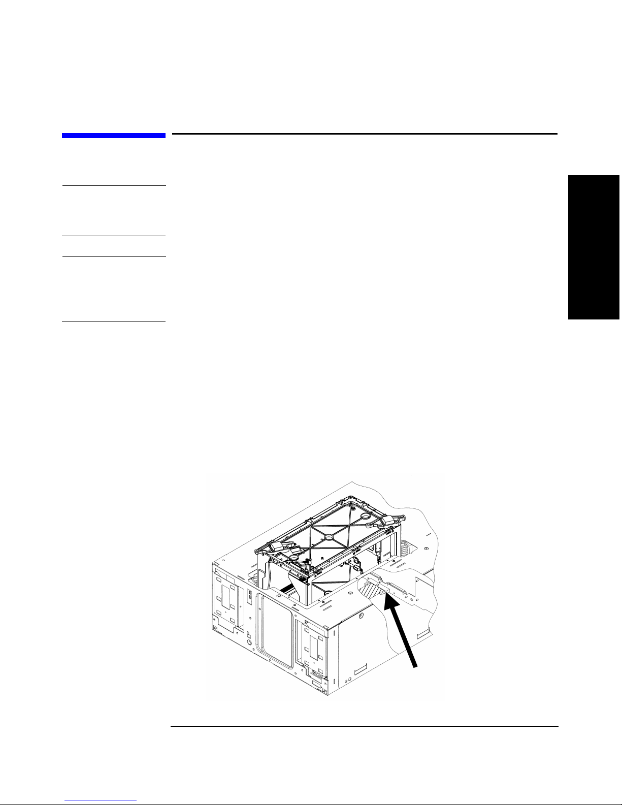
2. Install the interconnect cable from the motherboard on the upgrade
module to the motherboard on the existing library. The connection
should go from the top connector of the existing library to the bottom
connector of the upgrade module (Figure 4-9). Ensure the cable does
not interfere with other connectors.
CAUTION Align and install the interconnect cable as show in Figure 4-9. The pins
can become damaged if the cable is incorrectly installed.
Figure 4-9 Installing the Interconnect Cable
Chapter 4 4-13
Upgrading Library 6/140
Page 70

Upgrading Library Model 6/140
Securing the Upgrade Module to the Cabinet
3. Move the RFI cable to the top of the upgraded library to minimize
RFI interference (see Figure 4-10). The RFI cable is connected on the
back of the library and between the far left slot and the clip nut on
the library cabinet. Follow these steps to move the cable:
a. Loosen the thumbscrew on the left slot of the second highest
library module, and remove the RFI cable.
b. Install the clip nut so that it is even with the left slot on the
upgrade module (top of the library).
c. Loosen the thumbscrew on the left slot of the upgraded module,
and slide the RFI cable over this screw.
d. Tighten the thumbscrew.
e. Secure the other end of the cable to the clip nut on the left column
with one screw.
Figure 4-10 Installing the RFI Cable
Chapter 44-14
Page 71

Reassembling the Upgraded Library
1. Insert the front panel cosmetic doors by following these steps:
a. Remove the magazines at the front of the library.
b. Insert the cosmetic door’s connecting hooks through the holes in
the front of the door.
c. Holding the cosmetic door in place, align the holes in the sheet-
metal with the holes in the door (see Figure 4-11).
d. Push the sheet-metal tab downward so that the sheet-metal plate
clicks into place beneath the plastic tab.
e. Close the doors.
Figure 4-11 Installing the Cosmetic Doors
Upgrading Library Model 6/140
Reassembling the Upgraded Library
Chapter 4 4-15
Upgrading Library 6/140
Page 72

Upgrading Library Model 6/140
Reassembling the Upgraded Library
2. Install the filler panel(s) by easing it straight above the top of the
library. The filler panel is spring loaded.
3. Replace the library and cabinet side panels by following these steps:
a. Ease the side panel between the rails on the cabinet and the
library chassis.
b. Install the T-10 screws that secure the side panel to the library
(Figure 4-3 on page 4-5).
c. Tighten the side panels on the cabinet using a 3/16 Allen wrench
(Figure 4-2 on page 4-4).
4. Install the upgrade notice label to the right of the pull-out tabs on the
back of the library and on the fifth library level (Figure 4-12 on page
4-16). Add the second upgrade notice label underneath the front left
magazine on the lowest library module.
5. Add the upgrade serial number label to the bottom pull-out tab on the
back of the library.
Figure 4-12 Installing the Upgrade Labels
Chapter 44-16
Page 73

Upgrading Library Model 6/140
Reassembling the Upgraded Library
6. Install the cartridge identification labels by following these steps
(Figure 4-13):
a. Open the front panel doors on the upgrade module.
b. Select the cartridge identification label for your upgraded library.
— Select and install the 101-110 label on the left and 111-120 on
the right for a six-level library. The label is installed on the
inside sheet-metal edge of each door.
— Select and install the 121-130 label on the left and 131-140 on
the right for a seven-level library. The label is installed on the
inside sheet-metal edge of each door.
Figure 4-13 Installing the Cartridge Slot Numbering Labels
Chapter 4 4-17
Upgrading Library 6/140
Page 74

Upgrading Library Model 6/140
Verifying the Connection
Verifying the Connection
After connecting the hardware, you will need to verify the library
connection by completing the following:
• Powering on the library
• Running diagnostic tests
• Configuring the library
• Reconfiguring the backup software
Powering on the Library
1. Plug in the power cord one the upgrade module.
2. Connect the main power cords from the power distribution unit into a
grounded outlet.
3. Press the recessed standby (power) switch on the front of the library.
Running Diagnostic Tests
When you power on the library, it will automatically run an inventory
check. The inventory check will test for vertical alignment, drive/slot
availability, and electronics. Check the home page on the display to see
the overall health of the library and the availability of drives/slots. The
front panel display will also show any errors.
In addition to the inventory check, run the
tests to ensure the library is correctly configured. The
ensures a tape can be loaded into the drive. The
dynamically displays the state of the sensors. With this test, open and
close the doors and mailslot to toggle the sensors.
Wellness and Show All Sensors
Wellness test
Show All Sensors test
Chapter 44-18
Page 75

To run these tests:
Upgrading Library Model 6/140
Verifying the Connection
1. From
options. Select the
2. From
3. Select
Administration, select [More] to display additional administrative
Run Test menu.
Run Test, use the [-] or [+] key to view available tests.
[OK] to select the test.
4. Select the number of times this test will run (if needed).
NOTE Select [Stop] to abort a test. The current test cycle completes before the
test stops.
5. Select
[Run] to start the test cycle.
The test results will display at the conclusion of the test cycle.
Configuring the Library
Check the mailslot configuration. Since the mailslot will now be the top
right-hand drawer of the upgraded library, remove the tapes from the old
mailslot (0, 1, or 5 slots), and add them to the new mailslot on the top
module. When you power the library on, the library will automatically
reconfigure itself for the upgraded capacity and new mailslot.
The firmware automatically recognizes the upgrade status, so no
additional library configuration is needed.
Reconfiguring the Backup Software
Your software applications may need to be reconfigured or, in some cases,
reinstalled after you have installed additional drives or slots into the
library. In addition, some backup software applications may require the
purchase of additional add-on components and/or licenses when
increasing the number of storage slots or drives. Contact your software
application provider for more information or if newly installed storage
slots and drives are not recognized by your backup software application.
Chapter 4 4-19
Upgrading Library 6/140
 Loading...