

Page 1

HP A5500 EI & A5500 SI Switch Series
IP Multicast
Configuration Guide
Abstract
This document describes the software features for the HP A Series products and guides you through the
software configuration procedures. These configuration guides also provide configuration examples to
help you apply software features to different network scenarios.
This documentation is intended for network planners, field technical support and servicing engineers,
and network administrators working with the HP A Series products.
Part number: 5998-1712
Software version: Release 2208
Document version: 5W100-20110530
Page 2

Legal and notice information
© Copyright 2011 Hewlett-Packard Development Company, L.P.
No part of this documentation may be reproduced or transmitted in any form or by any means without
prior written consent of Hewlett-Packard Development Company, L.P.
The information contained herein is subject to change without notice.
HEWLETT-PACKARD COMPANY MAKES NO WARRANTY OF ANY KIND WITH REGARD TO THIS
MATERIAL, INCLUDING, BUT NOT LIMITED TO, THE IMPLIED WARRANTIES OF MERCHANTABILITY
AND FITNESS FOR A PARTICULAR PURPOSE. Hewlett-Packard shall not be liable for errors contained
herein or for incidental or consequential damages in connection with the furnishing, performance, or use
of this material.
The only warranties for HP products and services are set forth in the express warranty statements
accompanying such products and services. Nothing herein should be construed as constituting an
additional warranty. HP shall not be liable for technical or editorial errors or omissions contained herein.
Page 3

Contents
Multicast overview ······················································································································································· 1
Introduction to multicast ···················································································································································· 1
Comparison of information transmission techniques ···························································································· 1
Features of multicast ················································································································································· 3
Common notations in multicast ······························································································································· 4
Advantages and applications of multicast ············································································································· 4
Multicast models ································································································································································ 5
Multicast architecture ························································································································································ 5
Multicast addresses ·················································································································································· 6
Multicast protocols ··················································································································································· 9
Multicast packet forwarding mechanism ····················································································································· 11
Multi-instance multicast ·················································································································································· 12
Introduction to the multi-instance concept ··········································································································· 12
Multi-instance application in multicast ················································································································ 12
IGMP snooping configuration ··································································································································· 14
IGMP snooping overview ·············································································································································· 14
Principle of IGMP snooping ································································································································· 14
Basic concepts in IGMP snooping ······················································································································· 15
How IGMP snooping works ································································································································· 16
IGMP snooping proxying ····································································································································· 18
Protocols and standards ······································································································································· 19
IGMP snooping configuration task list ························································································································· 19
Configuring basic functions of IGMP snooping ·········································································································· 20
Configuration prerequisites ·································································································································· 20
Enabling IGMP snooping ····································································································································· 20
Configuring the version of IGMP snooping ········································································································ 21
Configuring static multicast MAC address entries ····························································································· 21
Configuring IGMP snooping port functions ················································································································· 22
Configuration prerequisites ·································································································································· 22
Configuring aging timers for dynamic ports ······································································································ 23
Configuring static ports ········································································································································ 23
Configuring simulated joining ······························································································································ 24
Configuring fast-leave processing ······················································································································· 25
Disabling a port from becoming a dynamic router port ··················································································· 26
Configuring IGMP snooping querier ··························································································································· 26
Configuration prerequisites ·································································································································· 26
Enabling IGMP snooping querier ························································································································ 27
Configuring IGMP queries and responses ·········································································································· 27
Configuring source IP address of IGMP queries ································································································ 28
Configuring IGMP snooping proxying ························································································································ 29
Configuration prerequisites ·································································································································· 29
Enabling IGMP snooping proxying ····················································································································· 29
Configuring a source IP address for the IGMP messages sent by the proxy ·················································· 29
Configuring an IGMP snooping policy ························································································································ 30
Configuration prerequisites ·································································································································· 30
Configuring a multicast group filter ····················································································································· 30
Configuring multicast source port filtering ·········································································································· 31
Configuring the function of dropping unknown multicast data ········································································ 31
Configuring IGMP report suppression ················································································································ 32
Configuring the maximum number of multicast groups that a port can join··················································· 32
iii
Page 4

Configuring multicast group replacement ··········································································································· 33
Configuring 802.1p precedence for IGMP messages ······················································································ 34
Configuring a multicast user control policy ········································································································ 35
Displaying and maintaining IGMP snooping ·············································································································· 36
IGMP snooping configuration examples ····················································································································· 36
Group policy and simulated joining configuration example ············································································ 36
Static port configuration example ······················································································································· 39
IGMP snooping querier configuration example ································································································· 42
IGMP snooping proxying configuration example ······························································································ 44
Multicast source and user control policy configuration example ····································································· 47
Troubleshooting IGMP snooping configuration ·········································································································· 52
Layer 2 multicast forwarding cannot function ···································································································· 52
Configured multicast group policy fails to take effect ······················································································· 53
Appendix (available only on the A5500 EI) ··············································································································· 53
Processing of multicast protocol messages ········································································································· 53
Multicast VLAN configuration ··································································································································· 55
Multicast VLAN overview ·············································································································································· 55
Multicast VLAN configuration task list ························································································································· 57
Configuring sub-VLAN-based multicast VLAN ············································································································ 57
Configuration prerequisites ·································································································································· 57
Configuring sub-VLAN-based multicast VLAN ···································································································· 57
Configuring port-based multicast VLAN ······················································································································ 58
Configuration prerequisites ·································································································································· 58
Configuring user port attributes ··························································································································· 58
Configuring multicast VLAN ports ······················································································································· 59
Displaying and maintaining multicast VLAN ·············································································································· 60
Multicast VLAN configuration examples ····················································································································· 60
Sub-VLAN-based multicast VLAN configuration ································································································· 60
Port-based multicast VLAN configuration ············································································································ 63
Multicast routing and forwarding configuration (available only on the A5500 EI) ·············································· 67
Multicast routing and forwarding overview ················································································································ 67
Introduction to multicast routing and forwarding ······························································································· 67
RPF check mechanism ··········································································································································· 67
Multicast static routes ············································································································································ 69
Multicast traceroute ··············································································································································· 71
Configuration task list ···················································································································································· 72
Enabling IP multicast routing ········································································································································· 72
Configuring multicast routing and forwarding ············································································································ 73
Configuration prerequisites ·································································································································· 73
Configuring multicast static routes ······················································································································· 73
Configuring a multicast routing policy ················································································································ 74
Configuring a multicast forwarding range ········································································································· 75
Configuring the multicast forwarding table size ································································································ 75
Tracing a multicast path ······································································································································· 76
Displaying and maintaining multicast routing and forwarding ················································································ 77
Configuration examples ················································································································································ 78
Changing an RPF route ········································································································································· 78
Creating an RPF route ··········································································································································· 80
Troubleshooting multicast routing and forwarding ····································································································· 82
Multicast static route failure ·································································································································· 82
Multicast data fails to reach receivers ················································································································ 83
IGMP configuration (available only on the A5500 EI) ··························································································· 84
IGMP overview ······························································································································································· 84
IGMP versions ························································································································································ 84
iv
Page 5

Introduction to IGMPv1 ········································································································································· 84
Enhancements in IGMPv2 ···································································································································· 86
Enhancements in IGMPv3 ···································································································································· 86
IGMP SSM mapping ············································································································································· 88
IGMP proxying ······················································································································································ 89
Multi-instance IGMP ·············································································································································· 90
Protocols and standards ······································································································································· 90
IGMP configuration task list ·········································································································································· 90
Configuring basic functions of IGMP ··························································································································· 91
Configuration prerequisites ·································································································································· 91
Enabling IGMP ······················································································································································ 91
Configuring IGMP versions ·································································································································· 92
Configuring static joining ····································································································································· 93
Configuring a multicast group filter ····················································································································· 93
Configuring the maximum number of multicast groups that an interface can join ········································ 94
Adjusting IGMP performance ······································································································································· 94
Configuration prerequisites ·································································································································· 94
Configuring IGMP message options ··················································································································· 95
Configuring IGMP query and response parameters ························································································· 96
Configuring IGMP fast-leave processing ············································································································ 98
Configuring IGMP SSM mapping ································································································································ 98
Configuration prerequisites ·································································································································· 98
Enabling SSM mapping········································································································································ 99
Configuring SSM mappings ································································································································· 99
Configuring IGMP proxying ········································································································································· 99
Configuration prerequisites ·································································································································· 99
Enabling IGMP proxying ···································································································································· 100
Configuring multicast forwarding on a downstream interface ······································································· 100
Displaying and maintaining IGMP ····························································································································· 101
IGMP configuration examples ···································································································································· 102
Basic IGMP functions configuration example ··································································································· 102
SSM mapping configuration example ·············································································································· 104
IGMP proxying configuration example ············································································································· 107
Troubleshooting IGMP ················································································································································· 109
No membership information on the receiver-side router ················································································· 109
Inconsistent memberships on routers on the same subnet ··············································································· 110
PIM configuration (available only on the A5500 EI) ··························································································· 111
PIM overview ································································································································································ 111
PIM-DM overview ················································································································································ 111
PIM-SM overview ················································································································································· 114
BIDIR-PIM overview ············································································································································· 120
Administrative scoping overview ······················································································································· 123
PIM-SSM overview ·············································································································································· 125
Relationships among PIM protocols ·················································································································· 126
Multi-instance PIM ··············································································································································· 127
Protocols and standards ····································································································································· 127
Configuring PIM-DM ···················································································································································· 128
PIM-DM configuration task list ··························································································································· 128
Configuration prerequisites ································································································································ 128
Enabling PIM-DM ················································································································································ 128
Enabling state-refresh capability ························································································································ 129
Configuring state-refresh parameters ················································································································ 130
Configuring PIM-DM graft retry period ············································································································· 130
Configuring PIM-SM ···················································································································································· 131
PIM-SM configuration task list ···························································································································· 131
v
Page 6

Configuration prerequisites ································································································································ 131
Enabling PIM-SM ················································································································································· 132
Configuring an RP ··············································································································································· 133
Configuring a BSR ··············································································································································· 135
Configuring administrative scoping ·················································································································· 139
Configuring multicast source registration ········································································································· 141
Disabling SPT switchover ···································································································································· 142
Configuring BIDIR-PIM ················································································································································· 143
BIDIR-PIM configuration task list ························································································································· 143
Configuration prerequisites ································································································································ 143
Enabling PIM-SM ················································································································································· 144
Enabling BIDIR-PIM ·············································································································································· 145
Configuring an RP ··············································································································································· 145
Configuring a BSR ··············································································································································· 147
Configuring administrative scoping ·················································································································· 151
Configuring PIM-SSM ·················································································································································· 153
PIM-SSM configuration task list ·························································································································· 153
Configuration prerequisites ································································································································ 153
Enabling PIM-SM ················································································································································· 154
Configuring the SSM group range ···················································································································· 155
Configuring PIM common features ····························································································································· 155
PIM common feature configuration task list ······································································································ 155
Configuration prerequisites ································································································································ 156
Configuring a multicast data filter ····················································································································· 156
Configuring a hello message filter ···················································································································· 157
Configuring PIM hello options ··························································································································· 157
Configuring the prune delay ······························································································································ 159
Configuring PIM common timers ······················································································································· 159
Configuring join/prune message sizes ············································································································· 161
Displaying and maintaining PIM ································································································································ 161
PIM configuration examples ······································································································································· 162
PIM-DM configuration example ························································································································· 162
PIM-SM non-scoped zone configuration example ··························································································· 166
PIM-SM admin-scope zone configuration example ························································································· 171
BIDIR-PIM configuration example ······················································································································ 177
PIM-SSM configuration example ······················································································································· 182
Troubleshooting PIM configuration ···························································································································· 185
Failure of building a multicast distribution tree correctly ················································································ 185
Multicast data abnormally terminated on an intermediate router ·································································· 186
RPs unable to join SPT in PIM-SM ······················································································································ 187
RPT establishment failure or source registration failure in PIM-SM ································································ 187
MSDP configuration (available only on the A5500 EI) ························································································ 189
Introduction to MSDP ··················································································································································· 189
How MSDP works ··············································································································································· 189
Multi-instance MSDP ··········································································································································· 194
Protocols and standards ····································································································································· 195
MSDP configuration task list ······································································································································· 195
Configuring basic functions of MSDP ························································································································ 195
Configuration prerequisites ································································································································ 195
Enabling MSDP ···················································································································································· 196
Creating an MSDP peer connection ·················································································································· 196
Configuring a static RPF peer ···························································································································· 197
Configuring an MSDP peer connection ····················································································································· 197
Configuration prerequisites ································································································································ 197
Configuring MSDP peer description ················································································································· 197
vi
Page 7

Configuring an MSDP mesh group ··················································································································· 198
Configuring MSDP peer connection control ····································································································· 198
Configuring SA messages related parameters ········································································································· 199
Configuration prerequisites ································································································································ 199
Configuring SA message content ······················································································································ 199
Configuring SA request messages ····················································································································· 200
Configuring SA message filtering rules ············································································································· 200
Configuring the SA cache mechanism ·············································································································· 201
Displaying and maintaining MSDP ···························································································································· 202
MSDP configuration examples ··································································································································· 202
Inter-AS multicast configuration leveraging BGP routes ·················································································· 202
Inter-AS multicast configuration leveraging static RPF peers ·········································································· 208
Anycast RP configuration ···································································································································· 211
SA message filtering configuration ··················································································································· 215
Troubleshooting MSDP ················································································································································ 218
MSDP peers stay in down state ························································································································· 218
No SA entries in the switch’s SA cache ············································································································ 219
Inter-RP communication faults in Anycast RP application ················································································ 219
MBGP configuration (available only on the A5500 EI) ······················································································· 220
MBGP overview ··························································································································································· 220
Protocols and standards ·············································································································································· 220
MBGP configuration task list ······································································································································· 220
Configuring MBGP basic functions ···························································································································· 221
Configuration prerequisites ································································································································ 221
Configuration procedure ···································································································································· 221
Controlling route advertisement and reception ········································································································· 222
Configuration prerequisites ································································································································ 222
Configuring MBGP route redistribution ············································································································· 222
Configure default route redistribution into MBGP ···························································································· 222
Configuring MBGP route summarization ·········································································································· 223
Advertising a default route to an IPv4 MBGP peer or peer group ································································ 224
Configuring outbound MBGP route filtering ····································································································· 224
Configuring inbound MBGP route filtering ······································································································· 225
Configuring MBGP route dampening ··············································································································· 226
Configuring MBGP route attributes ···························································································································· 226
Configuration prerequisites ································································································································ 226
Configuring MBGP route preferences ··············································································································· 226
Configuring the default local preference ·········································································································· 227
Configuring the MED attribute ··························································································································· 227
Configuring the Next Hop attribute ··················································································································· 228
Configuring the AS-PATH attribute ···················································································································· 228
Tuning and optimizing MBGP networks ···················································································································· 229
Configuration prerequisites ································································································································ 229
Configuring MBGP soft reset······························································································································ 229
Enabling the MBGP ORF capability ·················································································································· 230
Configuring the maximum number of MBGP routes for load balancing ······················································· 231
Configuring a large scale MBGP network ················································································································ 232
Configuration prerequisites ································································································································ 232
Configuring IPv4 MBGP peer groups ··············································································································· 232
Configuring MBGP community ·························································································································· 232
Configuring an MBGP route reflector ··············································································································· 233
Displaying and maintaining MBGP ··························································································································· 234
Displaying MBGP ················································································································································ 234
Resetting MBGP connections ······························································································································ 235
Clearing MBGP information ······························································································································· 235
vii
Page 8

MBGP configuration example ···································································································································· 236
MLD snooping configuration ·································································································································· 240
MLD snooping overview ·············································································································································· 240
Introduction to MLD snooping ···························································································································· 240
Basic concepts in MLD snooping ······················································································································· 241
How MLD snooping works ································································································································· 242
MLD snooping proxying ····································································································································· 244
Protocols and standards ····································································································································· 245
MLD snooping configuration task list ························································································································· 245
Configuring basic functions of MLD snooping ·········································································································· 246
Configuration prerequisites ································································································································ 246
Enabling MLD snooping ····································································································································· 246
Configuring the version of MLD snooping ········································································································ 247
Configuring IPv6 static multicast MAC address entries··················································································· 247
Configuring MLD snooping port functions ················································································································· 248
Configuration prerequisites ································································································································ 248
Configuring aging timers for dynamic ports ···································································································· 248
Configuring static ports ······································································································································ 249
Configuring simulated joining ···························································································································· 250
Configuring fast-leave processing ····················································································································· 250
Disabling a port from becoming a dynamic router port ················································································· 251
Configuring MLD snooping querier ··························································································································· 252
Configuration prerequisites ································································································································ 252
Enabling MLD snooping querier ························································································································ 252
Configuring MLD queries and responses ·········································································································· 253
Configuring source IPv6 addresses of MLD queries ························································································ 254
Configuring MLD snooping proxying ························································································································ 254
Configuration prerequisites ································································································································ 254
Enabling MLD snooping proxying ····················································································································· 254
Configuring a source IPv6 address for the MLD messages sent by the proxy ·············································· 255
Configuring an MLD snooping policy ························································································································ 255
Configuration prerequisites ································································································································ 255
Configuring an IPv6 multicast group filter ········································································································ 255
Configuring IPv6 multicast source port filtering ······························································································· 256
Configuring the function of dropping unknown IPv6 multicast data ······························································ 257
Configuring MLD report suppression ················································································································ 257
Configuring the maximum number of multicast groups that a port can join················································· 258
Configuring IPv6 multicast group replacement ································································································ 258
Configuring 802.1p precedence for MLD messages ······················································································ 259
Configuring an IPv6 multicast user control policy ···························································································· 260
Displaying and maintaining MLD snooping ·············································································································· 261
MLD snooping configuration examples ····················································································································· 262
IPv6 group policy and simulated joining configuration example ·································································· 262
Static port configuration example ····················································································································· 264
MLD snooping querier configuration example ································································································· 268
MLD snooping proxying configuration example ······························································································ 269
IPv6 multicast source and user control policy configuration example ··························································· 272
Troubleshooting MLD snooping ·································································································································· 277
Layer 2 multicast forwarding cannot function ·································································································· 277
Configured IPv6 multicast group policy fails to take effect ············································································· 278
Appendix (available only on the A5500 EI) ············································································································· 278
Processing of IPv6 multicast protocol messages······························································································· 278
IPv6 multicast VLAN configuration ························································································································· 280
IPv6 multicast VLAN overview ···································································································································· 280
IPv6 multicast VLAN configuration task list ··············································································································· 282
viii
Page 9

Configuring IPv6 sub-VLAN-based IPv6 multicast VLAN ························································································· 282
Configuration prerequisites ································································································································ 282
Configuring sub-VLAN-based IPv6 multicast VLAN ························································································· 282
Configuring port-based IPv6 multicast VLAN ············································································································ 283
Configuration prerequisites ································································································································ 283
Configuring user port attributes ························································································································· 283
Configuring IPv6 multicast VLAN ports ············································································································· 284
Displaying and maintaining IPv6 multicast VLAN ···································································································· 285
IPv6 multicast VLAN configuration examples ············································································································ 285
Sub-VLAN-based multicast VLAN configuration example ··············································································· 285
Port-based multicast VLAN configuration example ·························································································· 288
IPv6 multicast routing and forwarding configuration (available only on the A5500 EI) ··································· 292
IPv6 multicast routing and forwarding overview ······································································································ 292
RPF check mechanism ········································································································································· 292
Configuration task list ·················································································································································· 294
Enabling IPv6 multicast routing ·································································································································· 295
Configuring IPv6 multicast routing and forwarding ································································································· 295
Configuration prerequisites ································································································································ 295
Configuring an IPv6 multicast routing policy ··································································································· 295
Configuring an IPv6 multicast forwarding range ····························································································· 296
Configuring the IPv6 multicast forwarding table size ······················································································ 296
Displaying and maintaining IPv6 multicast routing and forwarding ······································································ 297
Troubleshooting IPv6 multicast policy configuration ································································································ 298
Abnormal termination of IPv6 multicast data ··································································································· 298
MLD configuration (available only on the A5500 EI) ·························································································· 300
MLD overview ······························································································································································· 300
MLD versions ························································································································································ 300
How MLDv1 works ·············································································································································· 300
How MLDv2 works ·············································································································································· 302
MLD Messages ···················································································································································· 303
MLD SSM mapping ············································································································································· 306
MLD proxying ······················································································································································ 307
Protocols and standards ····································································································································· 307
MLD configuration task list ·········································································································································· 308
Configuring basic functions of MLD ··························································································································· 308
Configuration prerequisites ································································································································ 308
Enabling MLD ······················································································································································ 309
Configuring the MLD version ····························································································································· 309
Configuring static joining ··································································································································· 310
Configuring an ipv6 multicast group filter ········································································································ 310
Configuring the maximum number of IPv6 multicast groups that an interface can join ······························ 311
Adjusting MLD performance ······································································································································· 311
Configuration prerequisites ································································································································ 311
Configuring MLD message options ··················································································································· 312
Configuring MLD query and response parameters ························································································· 313
Configuring MLD fast leave processing ············································································································ 315
Configuring MLD SSM mapping ································································································································ 315
Configuration prerequisites ································································································································ 315
Enabling MLD SSM mapping ····························································································································· 315
Configuring MLD SSM mappings ······················································································································ 316
Configuring MLD proxying ········································································································································· 316
Configuration prerequisites ································································································································ 316
Enabling MLD proxying ······································································································································ 316
Configuring IPv6 multicast forwarding on a downstream interface ······························································ 317
Displaying and maintaining MLD configuration ······································································································· 318
ix
Page 10

MLD configuration examples ······································································································································ 319
Basic MLD functions configuration example ····································································································· 319
MLD SSM mapping configuration example ····································································································· 321
MLD proxying configuration example ··············································································································· 324
Troubleshooting MLD ··················································································································································· 325
No member information on the receiver-side router ························································································ 325
Inconsistent memberships on routers on the same subnet ··············································································· 326
IPv6 PIM configuration (available only on the A5500 EI) ··················································································· 327
IPv6 PIM overview ························································································································································ 327
IPv6 PIM-DM overview ········································································································································ 327
IPv6 PIM-SM overview ········································································································································ 330
IPv6 BIDIR-PIM overview ····································································································································· 336
IPv6 administrative scoping overview ··············································································································· 340
IPv6 PIM-SSM overview ······································································································································ 342
Relationships among IPv6 PIM protocols ·········································································································· 344
Protocols and standards ····································································································································· 344
Configuring IPv6 PIM-DM ············································································································································ 345
IPv6 PIM-DM configuration task list ··················································································································· 345
Configuration prerequisites ································································································································ 345
Enabling IPv6 PIM-DM ········································································································································ 345
Enabling state-refresh capability ························································································································ 346
Configuring state refresh parameters ················································································································ 346
Configuring IPv6 PIM-DM graft retry period ···································································································· 347
Configuring IPv6 PIM-SM ············································································································································ 347
IPv6 PIM-SM configuration task list ··················································································································· 347
Configuration prerequisites ································································································································ 348
Enabling IPv6 PIM-SM········································································································································· 348
Configuring an RP ··············································································································································· 349
Configuring a BSR ··············································································································································· 351
Configuring IPv6 administrative scoping ·········································································································· 355
Configuring IPv6 multicast source registration ································································································· 356
Disabling SPT switchover ···································································································································· 357
Configuring IPv6 BIDIR-PIM ········································································································································· 358
IPv6 BIDIR-PIM configuration task list ················································································································ 358
Configuration prerequisites ································································································································ 358
Enabling IPv6 PIM-SM········································································································································· 359
Enabling IPv6 BIDIR-PIM ····································································································································· 359
Configuring an RP ··············································································································································· 359
Configuring a BSR ··············································································································································· 362
Configuring IPv6 administrative scoping ·········································································································· 365
Configuring IPv6 PIM-SSM ·········································································································································· 367
IPv6 PIM-SSM configuration task list ················································································································· 367
Configuration prerequisites ································································································································ 367
Enabling IPv6 PIM-SM········································································································································· 367
Configuring the IPv6 SSM group range ··········································································································· 368
Configuring IPv6 PIM common features ···················································································································· 368
IPv6 PIM common feature configuration task list ····························································································· 369
Configuration prerequisites ································································································································ 369
Configuring an IPv6 multicast data filter ·········································································································· 369
Configuring a hello message filter ···················································································································· 370
Configuring IPv6 PIM hello options ··················································································································· 370
Configuring the prune delay ······························································································································ 372
Configuring IPv6 PIM common timers ··············································································································· 372
Configuring join/prune message sizes ············································································································· 374
Displaying and maintaining IPv6 PIM ······················································································································· 374
x
Page 11

IPv6 PIM configuration examples ······························································································································· 375
IPv6 PIM-DM configuration example ················································································································· 375
IPv6 PIM-SM non-scoped zone configuration example ··················································································· 379
IPv6 PIM-SM admin-scope zone configuration example ················································································· 384
IPv6 BIDIR-PIM configuration example ·············································································································· 396
IPv6 PIM-SSM configuration example ··············································································································· 400
Troubleshooting IPv6 PIM configuration ···················································································································· 403
Failure to build a multicast distribution tree correctly ······················································································ 403
IPv6 multicast data abnormally terminated on an intermediate router ·························································· 404
RPs unable to join SPT in IPv6 PIM-SM ············································································································· 404
RPT establishment failure or source registration failure in IPv6 PIM-SM ························································ 405
IPv6 MBGP configuration (available only on the A5500 EI) ··············································································· 406
IPv6 MBGP overview ··················································································································································· 406
IPv6 MBGP configuration task list ······························································································································ 406
Configuring IPv6 MBGP basic functions ···················································································································· 407
Configuration prerequisites ································································································································ 407
Configuring an IPv6 MBGP peer ······················································································································· 407
Configuring a preferred value for routes from a peer/peer group ······························································· 408
Controlling route distribution and reception ············································································································· 408
Configuration prerequisites ································································································································ 408
Injecting a local IPv6 MBGP route ····················································································································· 408
Configuring IPv6 MBGP route redistribution ···································································································· 409
Configuring IPv6 MBGP route summarization ································································································· 409
Advertising a default route to a peer or peer group ······················································································· 409
Configuring outbound IPv6 MBGP route filtering ···························································································· 410
Configuring inbound IPv6 MBGP route filtering ······························································································ 411
Configuring IPv6 MBGP route dampening ······································································································· 411
Configuring IPv6 MBGP route attributes ···················································································································· 412
Configuration prerequisites ································································································································ 412
Configuring IPv6 MBGP route preferences ······································································································ 412
Configuring the default local preference ·········································································································· 412
Configuring the MED attribute ··························································································································· 413
Configuring the NEXT_HOP attribute ················································································································ 413
Configuring the AS_PATH attribute ··················································································································· 414
Tuning and optimizing IPv6 MBGP networks············································································································ 414
Configuration prerequisites ································································································································ 414
Configuring IPv6 MBGP soft reset ····················································································································· 414
Enabling the IPv6 MBGP ORF capability ········································································································· 415
Configuring the maximum number of equal-cost routes for load-balancing ················································· 417
Configuring a large scale IPv6 MBGP network ········································································································ 417
Configuration prerequisites ································································································································ 417
Configuring an IPv6 MBGP peer group ··········································································································· 417
Configuring IPv6 MBGP community ·················································································································· 418
Configuring an IPv6 MBGP route reflector ······································································································· 418
Displaying and maintaining IPv6 MBGP ··················································································································· 419
Displaying IPv6 MBGP ······································································································································· 419
Resetting IPv6 MBGP connections ····················································································································· 420
Clearing IPv6 MBGP information ······················································································································ 421
IPv6 MBGP configuration example ···························································································································· 421
Support and other resources ·································································································································· 424
Contacting HP ······························································································································································ 424
Subscription service ············································································································································ 424
Related information ······················································································································································ 424
Documents ···························································································································································· 424
Websites ······························································································································································ 424
xi
Page 12

Conventions ·································································································································································· 425
Index ········································································································································································ 427
xii
Page 13

Multicast overview
NOTE:
This document focuses on the IP multicast technology and device operations. Unless otherwise stated,
the term
multicast
Introduction to multicast
As a technique that coexists with unicast and broadcast, the multicast technique effectively addresses the
issue of point-to-multipoint data transmission. By enabling high-efficiency point-to-multipoint data
transmission over a network, multicast greatly saves network bandwidth and reduces network load.
By using multicast technology, a network operator can easily provide new value-added services, such as
live webcasting, web TV, distance learning, telemedicine, web radio, realtime video conferencing, and
other bandwidth-critical and time-critical information services.
Comparison of information transmission techniques
in this document refers to IP multicast.
Unicast
In unicast transmission, the information source must send a separate copy of information to each host
that needs the information.
Figure 1 Unicast transmission
Host A
Receiver
Host B
Source
Host C
Receiver
Host D
IP network
Packets for Host B
Packets for Host D
Packets for Host E
Receiver
Host E
In Figure 1, assume that Host B, Host D and Host E need the information. A separate transmission
channel must be established from the information source to each of these hosts.
1
Page 14
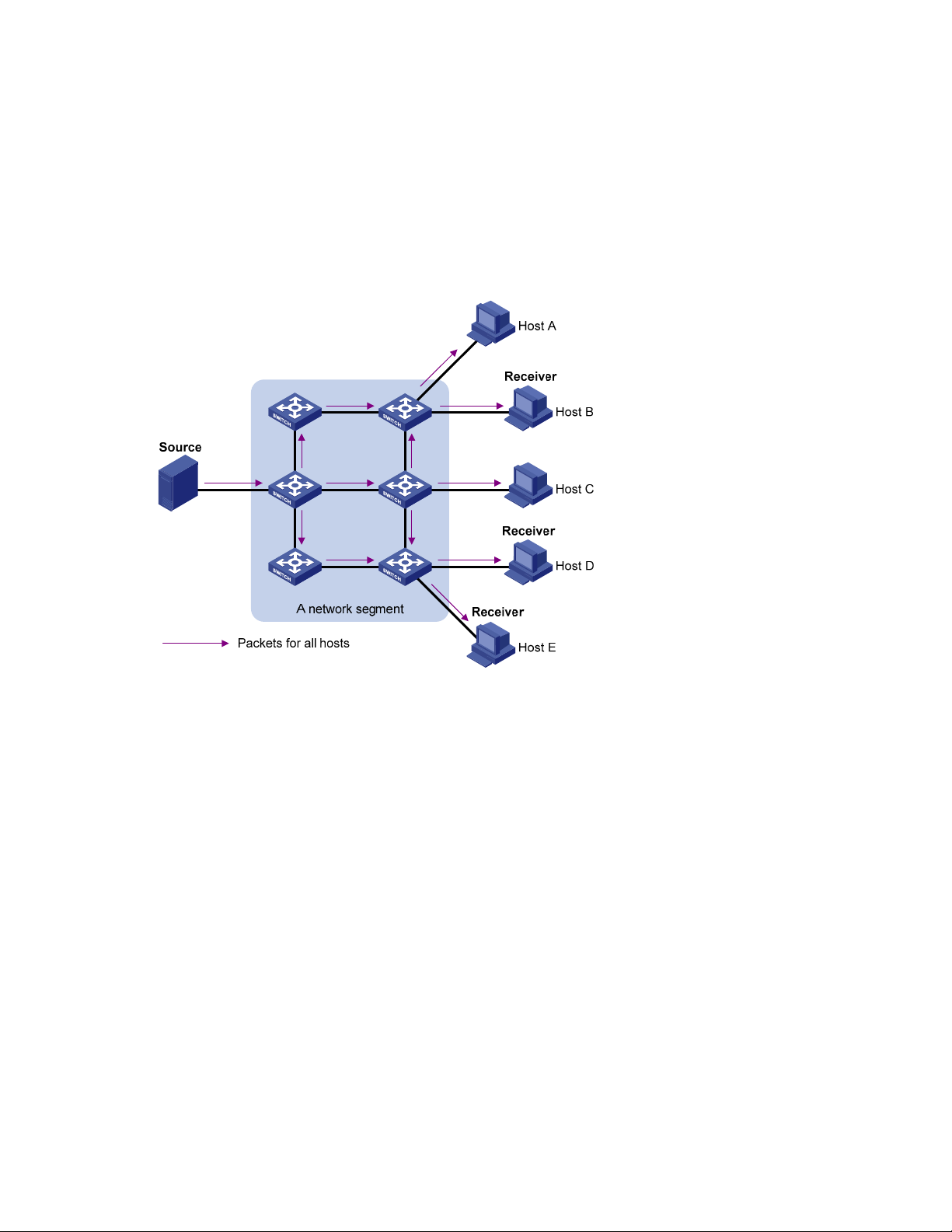
Broadcast
In unicast transmission, the traffic transmitted over the network is proportional to the number of hosts that
need the information. If a large number of hosts need the information, the information source must send
a copy of the same information to each of these hosts. Sending many copies can place a tremendous
pressure on the information source and the network bandwidth.
Unicast is not suitable for batch transmission of information.
In broadcast transmission, the information source sends information to all hosts on the subnet, even if
some hosts do not need the information.
Figure 2 Broadcast transmission
Multicast
In Figure 2, assume that only Host B, Host D, and Host E need the information. If the information is
broadcast to the subnet, Host A and Host C also receive it. In addition to information security issues,
broadcasting to hosts that do not need the information causes traffic flooding on the same subnet.
Broadcast is disadvantageous in transmitting data to specific hosts. Moreover, broadcast transmission is
a significant waste of network resources.
Unicast and broadcast techniques cannot provide point-to-multipoint data transmissions with the
minimum network consumption.
Multicast transmission can solve this problem. When some hosts on the network need multicast
information, the information sender, or multicast source, sends only one copy of the information.
Multicast distribution trees are built through multicast routing protocols, and the information is replicated
only on nodes where the trees branch.
2
Page 15
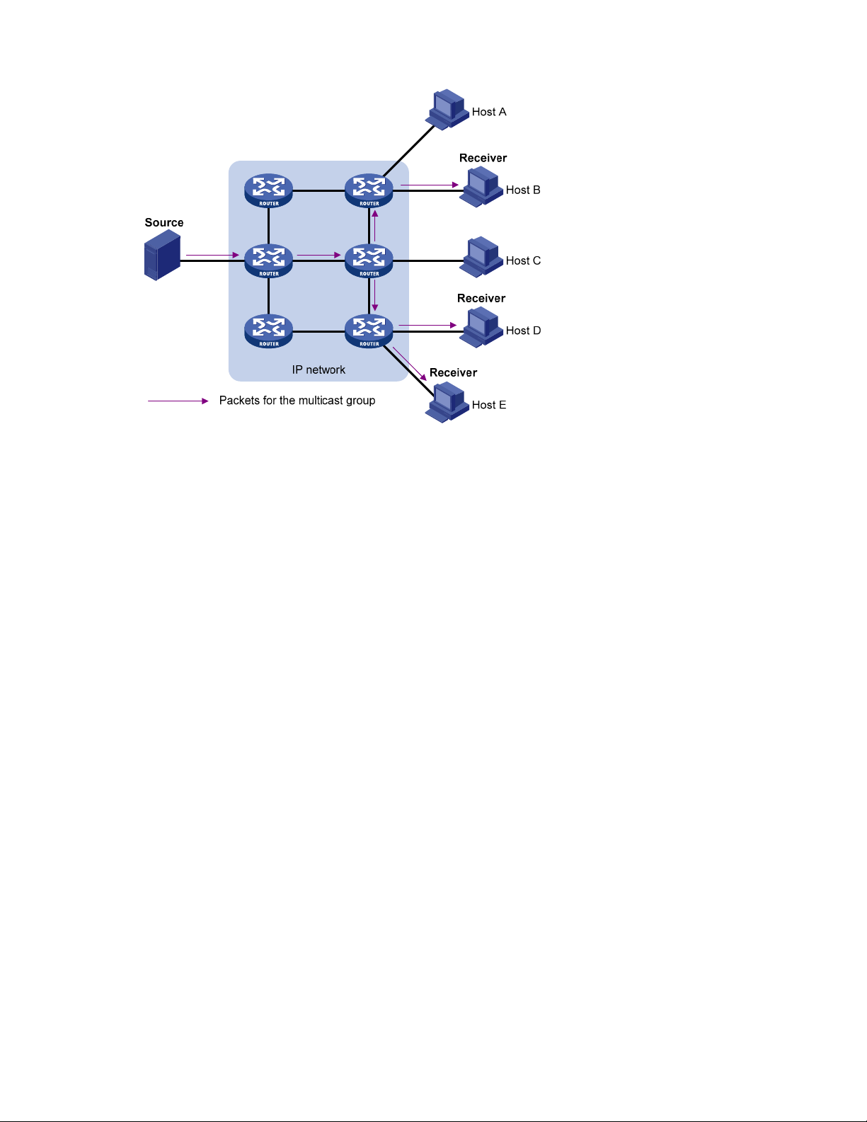
Figure 3 Multicast transmission
The multicast source sends only one copy of the information to a multicast group. In Figure 3, Host B,
Host D, and Host E, which are receivers of the information, must join the multicast group. The routers on
the network duplicate and forward the information based on the distribution of the group members.
Finally, the information is correctly delivered to Host B, Host D, and Host E.
To summarize, multicast has the following advantages:
• Advantages over unicast: Because multicast traffic flows to the farthest-possible node from the
source before it is replicated and distributed, an increase in the number of hosts does not increase
the load of the source or remarkably add to the usage of network resources.
• Advantages over broadcast: Because multicast data is sent only to the receivers that need it,
multicast uses network bandwidth reasonably and enhances network security. In addition, data
broadcast is confined to the same subnet, but multicast is not.
Features of multicast
Multicast transmission has the following features:
• A multicast group is a multicast receiver set identified by an IP multicast address. Hosts join a
multicast group to become members of the multicast group before they can receive the multicast
data addressed to that multicast group. Typically, a multicast source does not need to join a
multicast group.
• An information sender is called a “multicast source.” A multicast source can send data to multiple
multicast groups at the same time, and multiple multicast sources can send data to the same
multicast group at the same time.
• All hosts that have joined a multicast group become members of the multicast group. The group
memberships are dynamic. Hosts can join or leave multicast groups at any time. Multicast groups
are not subject to geographic restrictions.
• Routers or Layer 3 switches that support Layer 3 multicast are called “multicast routers” or “Layer 3
multicast devices.” In addition to providing the multicast routing function, a multicast router can
3
Page 16

manage multicast group memberships on stub subnets with attached group members. A multicast
router itself can be a multicast group member.
For a better understanding of the multicast concept, you can compare multicast transmission to the
transmission of TV programs.
Table 1 An analogy between TV transmission and multicast transmission
TV transmission Multicast transmission
A TV station transmits a TV program through a
channel.
A user tunes the TV set to the channel. A receiver joins the multicast group.
The user starts to watch the TV program
transmitted by the TV station via the channel.
The user turns off the TV set or tunes to another
channel.
Common notations in multicast
The following notations are commonly used in multicast transmission:
• (*, G)—Indicates a rendezvous point tree (RPT), or a multicast packet that any multicast source
sends to multicast group G. Here, the asterisk represents any multicast source, and “G” represents
a specific multicast group.
• (S, G)—Indicates a shortest path tree (SPT), or a multicast packet that multicast source S sends to
multicast group G. Here, “S” represents a specific multicast source, and “G” represents a specific
multicast group.
NOTE:
A multicast source sends multicast data to a multicast
group.
The receiver starts to receive the multicast data that the
source is sending to the multicast group.
The receiver leaves the multicast group or joins another
group.
For more information about the concepts RPT and SPT, see the chapters “PIM configuration”
PIM configuration.”
Advantages and applications of multicast
Advantages of multicast
The multicast technique has the following advantages:
• Enhanced efficiency—Reduces the processor load of information source servers and network
devices.
• Optimal performance—Reduces redundant traffic.
• Distributed application—Enables point-to-multipoint applications at the price of minimum network
resources.
Applications of multicast
The multicast technique has the following applications:
• Multimedia and streaming applications, such as web TV, web radio, and realtime video/audio
conferencing
4
and “IPv6
Page 17

• Communication for training and cooperative operations, such as distance learning and
telemedicine
• Data warehouse and financial applications, such as stock quotes
• Any other point-to-multipoint applications for data distribution
Multicast models
Based on how the receivers treat the multicast sources, the multicast models include any-source multicast
(ASM), source-filtered multicast (SFM), and source-specific multicast (SSM).
ASM model
In the ASM model, any sender can send information to a multicast group as a multicast source, and
numbers of receivers can join a multicast group (identified by a group address) and can obtain multicast
information addressed to that multicast group. In this model, receivers do not determine the positions of
the multicast sources in advance. However, they can join or leave the multicast group at any time.
SFM model
The SFM model is derived from the ASM model. To a sender, the two models appear to have the same
multicast membership architecture.
The SFM model functionally extends the ASM model. The upper-layer software checks the source address
of received multicast packets and permits or denies multicast traffic from specific sources. Therefore,
receivers can receive the multicast data from only part of the multicast sources. To a receiver, not all
multicast sources are valid: they are filtered.
SSM model
Users might be interested in the multicast data from only certain multicast sources. The SSM model
provides a transmission service that enables users to specify the multicast sources that they are interested
in at the client side.
The main difference between the SSM model and the ASM model is that in the SSM model, receivers
have already determined the locations of the multicast sources by some other means. In addition, the
SSM model uses a multicast address range that is different from that of the ASM/SFM model, and
dedicated multicast forwarding paths are established between receivers and the specified multicast
sources.
Multicast architecture
IP multicast addresses the following questions:
• Where should the multicast source transmit information to? (multicast addressing)
• What receivers exist on the network? (host registration)
• Where is the multicast source that will provide data to the receivers? (multicast source discovery)
• How should information be transmitted to the receivers? (multicast routing)
IP multicast is an end-to-end service. The multicast architecture involves the following parts:
1. Addressing mechanism—A multicast source sends information to a group of receivers through a
multicast address.
2. Host registration—Receiver hosts can join and leave multicast groups dynamically. This mechanism
is the basis for management of group memberships.
5
Page 18

3. Multicast routing—A multicast distribution tree—a forwarding path tree for multicast data on the
network—is constructed for delivering multicast data from a multicast source to receivers.
4. Multicast applications—A software system that supports multicast applications, such as video
conferencing, must be installed on multicast sources and receiver hosts. The TCP/IP stack must
support reception and transmission of multicast data.
Multicast addresses
Network-layer multicast addresses—namely, multicast IP addresses—enable communication between
multicast sources and multicast group members. In addition, a technique must be available to map
multicast IP addresses to link-layer multicast MAC addresses.
IP multicast addresses
1. IPv4 multicast addresses
Internet Assigned Numbers Authority (IANA) assigned the Class D address space—224.0.0.0 to
239.255.255.255—for IPv4 multicast.
Table 2 Class D IP address blocks and description
Address block Description
224.0.0.0 to 224.0.0.255
Reserved permanent group addresses. The IP address 224.0.0.0
is reserved. Other IP addresses can be used by routing protocols
and for topology searching, protocol maintenance, and so on.
Table 3 lists common permanent group addresses. A packet
destined for an address in this block will not be forwarded
beyond the local subnet regardless of the Time to Live (TTL) value
in the IP header.
Globally scoped group addresses. This block includes the
224.0.1.0 to 238.255.255.255
following types of designated group addresses:
• 232.0.0.0/8—SSM group addresses
• 233.0.0.0/8—Glop group addresses
Administratively scoped multicast addresses. These addresses are
239.0.0.0 to 239.255.255.255
considered locally unique rather than globally unique, and can
be reused in domains administered by different organizations
without causing conflicts. For more information, see RFC 2365.
NOTE:
The membership of a group is dynamic. Hosts can join or leave multicast groups at any time.
“Glop” is a mechanism for assigning multicast addresses between different autonomous systems
(ASs). By filling an AS number into the middle two bytes of 233.0.0.0, you get 255 multicast
addresses for that AS. For more information, see RFC 2770.
Table 3 Some reserved multicast addresses
Address Description
224.0.0.1 All systems on this subnet, including hosts and routers
224.0.0.2 All multicast routers on this subnet
224.0.0.3 Unassigned
6
Page 19

Address Description
p
224.0.0.4 Distance Vector Multicast Routing Protocol (DVMRP) routers
224.0.0.5 Open Shortest Path First (OSPF) routers
224.0.0.6 OSPF designated routers and backup designated routers
224.0.0.7 Shared Tree (ST) routers
224.0.0.8 ST hosts
224.0.0.9 Routing Information Protocol version 2 (RIPv2) routers
224.0.0.11 Mobile agents
224.0.0.12 Dynamic Host Configuration Protocol (DHCP) server/relay agent
224.0.0.13 All Protocol Independent Multicast (PIM) routers
224.0.0.14 Resource Reservation Protocol (RSVP) encapsulation
224.0.0.15 All Core-Based Tree (CBT) routers
224.0.0.16 Designated Subnetwork Bandwidth Management (SBM)
224.0.0.17 All SBMs
224.0.0.18 Virtual Router Redundancy Protocol (VRRP)
2. IPv6 multicast addresses
Figure 4 IPv6 multicast format
The following describes the fields of an IPv6 multicast address:
• 0xFF—The most significant eight bits are 11111111, which indicates that this address is an IPv6
multicast address.
• Flags—The Flags field contains four bits.
Figure 5 Format of the Flags field
Table 4 Description on the bits of the Flags field
Bit Descri
0 Reserved, set to 0
tion
• When set to 0, it indicates that this address is an IPv6 multicast address without an
R
embedded RP address.
• When set to 1, it indicates that this address is an IPv6 multicast address with an
embedded RP address—the P and T bits must also be set to 1.
7
Page 20

Bit Description
g
• When set to 0, it indicates that this address is an IPv6 multicast address not based on
P
a unicast prefix.
• When set to 1, it indicates that this address is an IPv6 multicast address based on a
unicast prefix—the T bit must also be set to 1.
• When set to 0, it indicates that this address is an IPv6 multicast address permanently-
T
assigned by IANA.
• When set to 1, it indicates that this address is a transient, or dynamically assigned
IPv6 multicast address.
• Scope—The Scope field contains four bits, which indicate the scope of the IPv6 internetwork for
which the multicast traffic is intended.
Table 5 Values of the Scope field
Value Meanin
0, F Reserved
1 Interface-local scope
2 Link-local scope
3 Subnet-local scope
4 Admin-local scope
5 Site-local scope
6, 7, 9 through D Unassigned
8 Organization-local scope
E Global scope
• Group ID—The Group ID field contains 112 bits. It uniquely identifies an IPv6 multicast group in the
scope that the Scope field defines.
Ethernet multicast MAC addresses
When a unicast IP packet is transmitted over Ethernet, the destination MAC address is the MAC address
of the receiver. When a multicast packet is transmitted over Ethernet, the destination address is a
multicast MAC address because the packet is directed to a group formed by a number of receivers,
rather than to one specific receiver.
1. IPv4 multicast MAC addresses
As defined by IANA, the most-significant 24 bits of an IPv4 multicast MAC address are 0x01005E. Bit
25 is 0, and the least-significant 23 bits are the least-significant 23 bits of a multicast IPv4 address.
8
Page 21
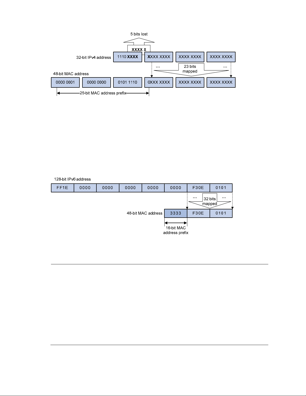
Figure 6 IPv4-to-MAC address mapping
The most-significant four bits of a multicast IPv4 address are 1110, which indicates that this address is a
multicast address. Only 23 bits of the remaining 28 bits are mapped to a MAC address, so five bits of
the multicast IPv4 address are lost. As a result, 32 multicast IPv4 addresses map to the same IPv4
multicast MAC address. Therefore, in Layer 2 multicast forwarding, a switch might receive some
multicast data destined for other IPv4 multicast groups. The upper layer must filter such redundant data.
2. IPv6 multicast MAC addresses
The most-significant 16 bits of an IPv6 multicast MAC address are 0x3333. The least-significant 32 bits
are the least-significant 32 bits of a multicast IPv6 address.
Figure 7 An example of IPv6-to-MAC address mapping
Multicast protocols
NOTE:
Generally,
protocols are Layer 3 multicast protocols, which include IGMP, MLD, PIM, IPv6 PIM, MSDP, MBGP,
and IPv6 MBGP.
multicast protocols are Layer 2 multicast protocols, which include IGMP snooping, MLD snooping,
multicast VLAN, and IPv6 multicast VLAN.
IGMP snooping, IGMP, multicast VLAN, PIM, MSDP, and MBGP are for IPv4. MLD snooping, MLD,
IPv6 multicast VLAN, IPv6 PIM, and IPv6 MBGP are for IPv6.
Layer 3 multicast
Layer 2 multicast refers to
refers to IP multicast working at the network layer. The related multicast
IP multicast working at the data link layer. The related
This section provides only general descriptions about applications and functions of the Layer 2 and
Layer 3 multicast protocols in a network. For more information about these protocols, see related
chapters.
9
Page 22

Layer 3 multicast protocols
Layer 3 multicast protocols include multicast group management protocols and multicast routing
protocols.
Figure 8 Positions of Layer 3 multicast protocols
1. Multicast group management protocols
Typically, the Internet Group Management Protocol (IGMP) or Multicast Listener Discovery Protocol (MLD)
is used between hosts and Layer 3 multicast devices that directly connect to the hosts. These protocols
define the mechanism of establishing and maintaining group memberships between hosts and Layer 3
multicast devices.
2. Multicast routing protocols
A multicast routing protocol runs on Layer 3 multicast devices to establish and maintain multicast routes
and forward multicast packets correctly and efficiently. Multicast routes constitute loop-free data
transmission paths from a data source to multiple receivers, namely, a multicast distribution tree.
In the ASM model, multicast routes include intra-domain routes and inter-domain routes.
• An intra-domain multicast routing protocol discovers multicast sources and builds multicast
distribution trees within an AS to deliver multicast data to receivers. Among a variety of mature
intra-domain multicast routing protocols, Protocol Independent Multicast (PIM) is most widely used.
Based on the forwarding mechanism, PIM includes the dense mode—often called “PIM-DM”, and
sparse mode—often called “PIM-SM.”
• An inter-domain multicast routing protocol delivers multicast information between two ASs. Mature
solutions include Multicast Source Discovery Protocol (MSDP) and Multicast Border Gateway
Protocol (MBGP). MSDP propagates multicast source information among different ASs, and MBGP
is an extension of the Multiprotocol Border Gateway Protocol (MP-BGP) for exchanging multicast
routing information among different ASs.
For the SSM model, multicast routes are not divided into intra-domain routes and inter-domain routes.
Because receivers know the positions of the multicast sources, channels established through PIM-SM are
sufficient for the transport of multicast information.
Layer 2 multicast protocols
Layer 2 multicast protocols include IGMP snooping, MLD snooping, multicast VLAN, and IPv6 multicast
VLAN.
10
Page 23
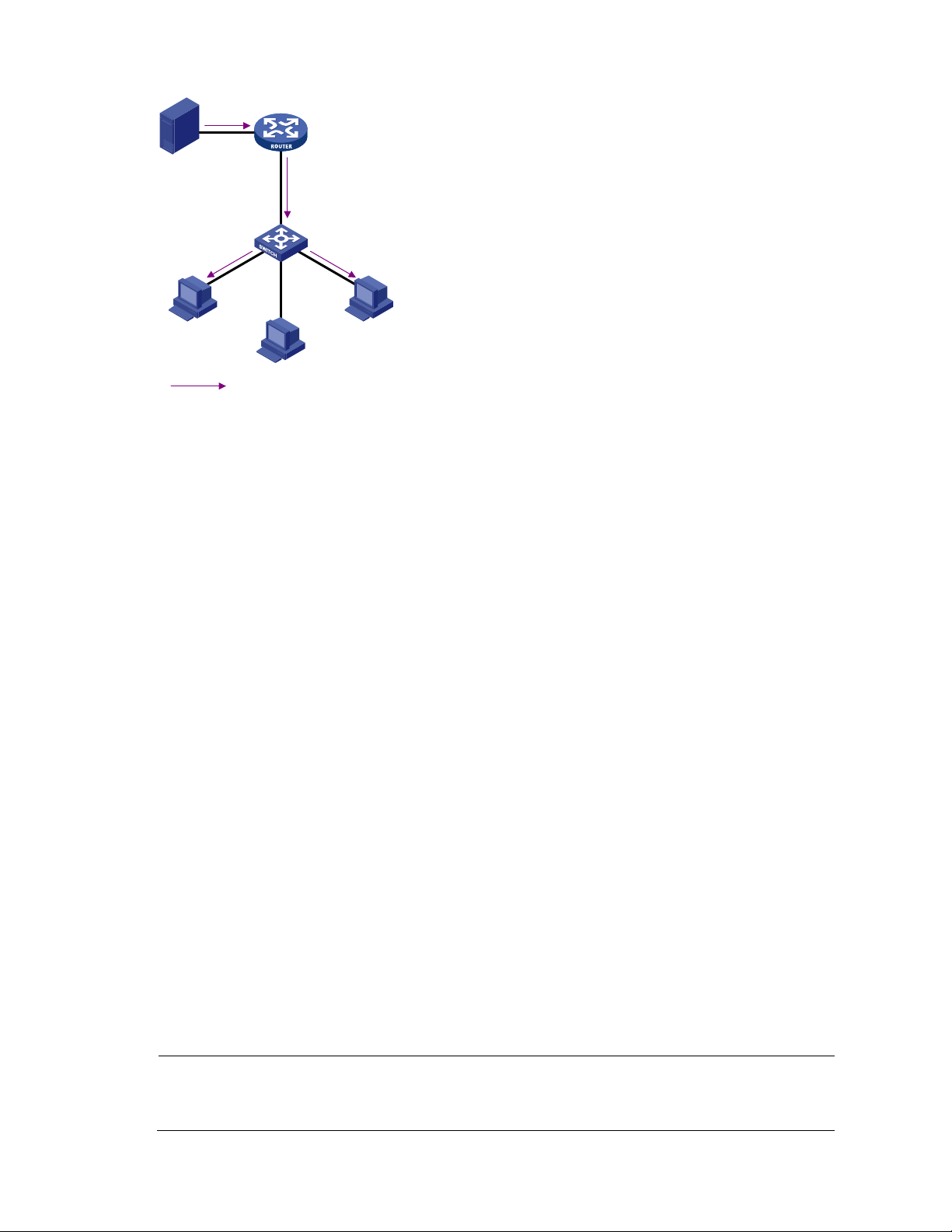
Figure 9 Positions of Layer 2 multicast protocols
Source
Receiver Receiver
IPv4/IPv6 multicast packets
1. IGMP snooping and MLD snooping
Multicast VLAN
/IPv6 Multicast VLAN
IGMP Snooping
/MLD Snooping
IGMP snooping and MLD snooping are multicast constraining mechanisms that run on Layer 2 devices.
They manage and control multicast groups by monitoring and analyzing IGMP or MLD messages
exchanged between the hosts and Layer 3 multicast devices, effectively controlling the flooding of
multicast data in a Layer 2 network.
2. Multicast VLAN and IPv6 multicast VLAN
In the traditional multicast-on-demand mode, when users in different VLANs on a Layer 2 device need
multicast information, the upstream Layer 3 device needs to forward a separate copy of the multicast
data to each VLAN of the Layer 2 device. When the multicast VLAN or IPv6 multicast VLAN feature is
enabled on the Layer 2 device, the Layer 3 multicast device sends only one copy of the multicast data to
the multicast VLAN or IPv6 multicast VLAN on the Layer 2 device. This approach avoids waste of
network bandwidth and extra burden on the Layer 3 device.
Multicast packet forwarding mechanism
In a multicast model, a multicast source sends information to the host group identified by the multicast
group address in the destination address field of IP multicast packets. To deliver multicast packets to
receivers located at different positions of the network, multicast routers on the forwarding paths usually
need to forward multicast packets received on one incoming interface to multiple outgoing interfaces.
Compared with a unicast model, a multicast model is more complex in the following aspects:
• To ensure multicast packet transmission in the network, unicast routing tables or multicast routing
tables—for example, MBGP routing table—specially provided for multicast must be used as
guidance for multicast forwarding.
• To process the same multicast information from different peers received on different interfaces of the
same device, every multicast packet undergoes a reverse path forwarding (RPF) check on the
incoming interface. The result of the RPF check determines whether the packet will be forwarded or
discarded. The RPF check mechanism is the basis for most multicast routing protocols to implement
multicast forwarding.
NOTE:
For more information about the RPF mechanism, see the chapters “Multicast routing and forwarding
configuration” and “IPv6 multicast routing and forwarding configuration.”
11
Page 24

Multi-instance multicast
Multi-instance multicast refers to multicast in virtual private networks (VPNs).
Introduction to the multi-instance concept
VPN networks must be isolated from one another and from the public network.
Figure 10 Networking diagram for VPN
VPN A
CE a2
CE b3
VPN BVPN B
CE a3
PE 3
VPN A
CE b1
CE a1
VPN A
CE b2
PE 1
PE 2
P
Public network
As shown in Figure 10, VPN A and VPN B separately access the public network through PE devices. The
devices in the network are as follows:
• The P device belongs to the public network. The CE devices belong to their respective VPNs. Each
CE device serves its own network and maintains only one set of forwarding mechanism.
• The PE devices connect to the public network and the VPN networks at the same time. Each PE
device must strictly distinguish the information for different networks, and must maintain a separate
forwarding mechanism for each network. On a PE device, a set of software and hardware that
serves the same network forms an instance. Multiple instances exist on a PE device at the same
time, and an instance resides on different PE devices.
Multi-instance application in multicast
With multi-instance multicast enabled, a PE can do the following operations:
• Maintain a set of independent multicast forwarding mechanisms for each instance, including
various multicast protocols, a list of PIM neighbors, and a multicast routing table per instance. Each
instance searches its own forwarding table or routing table to forward multicast data.
• Guarantee the isolation between different VPN instances.
12
Page 25

• Implement information exchange and data conversion between the public network and VPN
instances.
NOTE:
Only one set of unified multicast service runs on a non-PE device. It is called a “public network.”
The configuration made in VPN instance view takes effect only on the VPN instance interface. An
interface that does not belong to any VPN instance is called a “public network interface.”
13
Page 26
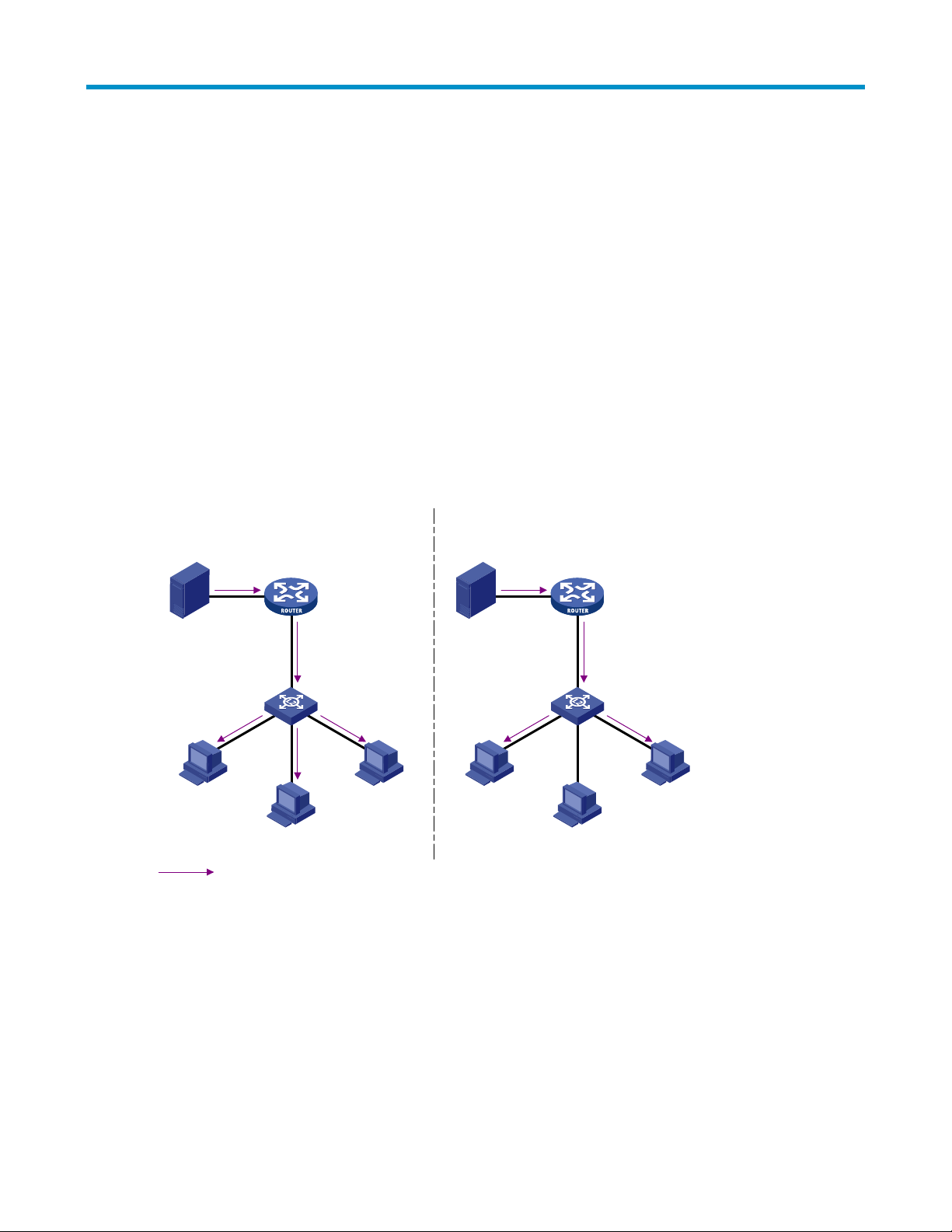
IGMP snooping configuration
IGMP snooping overview
IGMP snooping is a multicast constraining mechanism that runs on Layer 2 devices to manage and
control multicast groups.
Principle of IGMP snooping
By analyzing received IGMP messages, a Layer 2 switch that runs IGMP snooping establishes mappings
between ports and multicast MAC addresses, and forwards multicast data based on these mappings.
When IGMP snooping is not running on the switch, multicast packets are flooded to all devices at Layer
2. When IGMP snooping runs on the switch, multicast packets for known multicast groups are multicast
to the receivers, rather than being broadcast to all hosts, at Layer 2.
Figure 11 Before and after IGMP snooping is enabled on the Layer 2 device
Source
Multicast packet transmission
without IGMP Snooping
Host A
Receiver
Host B
Multicast packets
Multicast router
Layer 2 switch
Host C
Receiver
Multicast packet transmission
when IGMP Snooping runs
Source
Host A
Receiver
Host B
Multicast router
Layer 2 switch
Host C
Receiver
IGMP snooping forwards multicast data to only the receivers that require the data at Layer 2. It has the
following advantages:
• Reducing Layer 2 broadcast packets, saving network bandwidth
• Enhancing the security of multicast traffic
• Facilitating the implementation of per-host accounting
14
Page 27

Basic concepts in IGMP snooping
IGMP snooping related ports
In Figure 12, Router A connects to the multicast source, IGMP snooping runs on Switch A and Switch B,
and Host A and Host C are receiver hosts—also called “multicast group members.”
Figure 12 IGMP snooping related ports
Router A Switch A
GE1/0/1 GE1/0/2
GE1/0/3
GE1/0/1
Source
Switch B
Router port
Member port
Multicast packets
Receiver
GE1/0/2
Host C
Host D
Receiver
Host A
Host B
IGMP snooping involves the following ports:
• Router port—A router port is a port on a Layer 2 switch that leads toward a Layer 3 multicast
device—DR or IGMP querier. In Figure 12, G
igabitEthernet 1/0/1 of Switch A and
GigabitEthernet 1/0/1 of Switch B are router ports. Each switch registers all its local router ports in
its router port list.
• Member port—A member port is a port on a Layer 2 switch that leads toward multicast group
members. In Figure 12, GigabitEthern
et 1/0/2 and GigabitEthernet 1/0/3 of Switch A and
GigabitEthernet 1/0/2 of Switch B are member ports. Each switch registers all the member ports
on the local device in its IGMP snooping forwarding table.
NOTE:
Whenever mentioned in this document, a router port is a port on the switch that leads the switch to a
Layer 3 multicast device, rather than a port on a router.
Unless otherwise specified, router/member ports mentioned in this document include static and
dynamic ports.
An IGMP-snooping-enabled switch deems that all its ports on which IGMP general queries with the
source IP address other than 0.0.0.0 or PIM hello messages are received are dynamic router ports.
For more information about PIM hello messages, see the chapter “PIM configuration.”
15
Page 28

piry
g
Aging timers for dynamic ports in IGMP snooping and related messages and actions
Timer Description
For each dynamic router
Dynamic router port
aging timer
Dynamic member port
aging timer
port, the switch sets a
timer initialized to the
dynamic router port
aging time.
When a port
dynamically joins a
multicast group, the
switch sets a timer for
the port, which is
initialized to the
dynamic member port
aging time.
NOTE:
The port aging mechanism of IGMP snooping works only for dynamic ports; a static port will never a
out.
How IGMP snooping works
Message before
ex
IGMP general query of
which the source
address is not 0.0.0.0
or PIM hello
IGMP membership
report
Action after expiry
The switch removes this
port from its router port
list.
The switch removes this
port from the IGMP
snooping forwarding
table.
e
A switch that runs IGMP snooping performs different actions when it receives different IGMP messages.
CAUTION:
The description about adding or deleting a port in this section is only for a dynamic port. Static ports
can be added or deleted only through the specific configurations. For more information, see
“Configuring static ports.”
When receiving a general query
The IGMP querier periodically sends IGMP general queries to all hosts and routers—224.0.0.1—on the
local subnet to determine whether active multicast group members exist on the subnet.
After receiving an IGMP general query, the switch forwards it through all ports in the VLAN (except the
port that received the query). The switch also performs the following judgment:
• If the port that received the query is a dynamic router port that exists in its router port list, the switch
resets the aging timer for this dynamic router port.
• If the port is not a dynamic router port that exists in its router port list, the switch adds it into its
router port list and sets an aging timer for this dynamic router port.
When receiving a membership report
A host sends an IGMP report to the IGMP querier in the following circumstances:
• If the host is already a member of a multicast group, the host responds with an IGMP report after
receiving an IGMP query.
• If the host wants to join a multicast group, the host sends an IGMP report to the IGMP querier to
announce that it is interested in the multicast information addressed to that group.
16
Page 29

A
NOTE:
After receiving an IGMP report, the switch forwards it through all the router ports in the VLAN, resolves
the address of the reported multicast group. The switch also performs the following judgment:
• If no entry in the forwarding table exists for the reported group, the switch creates an entry, adds
the port as a dynamic member port to the outgoing port list, and starts a member port aging timer
for that port.
• If an entry in the forwarding table exists for the reported group but the port is not included in the
outgoing port list for that group, the switch adds the port as a dynamic member port to the
outgoing port list and starts an aging timer for that port.
• If an entry in the forwarding table exists for the reported group and the port is included in the
outgoing port list, which means that this port is already a dynamic member port, the switch resets
the aging timer for that port.
switch does not forward an IGMP report through a non-router port. The reason is that if the switch
forwards a report message through a member port, all the attached hosts that are monitoring the
reported multicast address suppress their own reports after receiving this report according to the IGMP
report suppression mechanism. This prevents the switch from determining whether the reported
multicast group still has active members attached to that port. For more information about the IGMP
report suppression mechanism, see the chapter “IGMP configuration.”
When receiving a leave message
When an IGMPv1 host leaves a multicast group, the host does not send an IGMP leave message, so the
switch cannot determine immediately that the host has left the multicast group. However, as the host
stops sending IGMP reports as soon as it leaves a multicast group, the switch deletes the forwarding
entry for the dynamic member port that corresponds to the host from the forwarding table when its aging
timer expires.
When an IGMPv2 or IGMPv3 host leaves a multicast group, the host sends an IGMP leave message to
the multicast router.
When the switch receives an IGMP leave message on a dynamic member port, the switch first
determines whether an entry in the forwarding table exists for the group address in the message, and, if
one exists, whether the outgoing port list contains the port.
• If the entry in the forwarding table does not exist or if the outgoing port list does not contain the
port, the switch discards the IGMP leave message instead of forwarding it to any port.
• If the entry in the forwarding table exists and the outgoing port list contains the port, the switch
forwards the leave message to all router ports in the native VLAN. Because the switch cannot
determine whether any other hosts attached to the port are still monitoring that group address, the
switch does not immediately remove the port from the outgoing port list of the entry in the
forwarding table for that group. Instead, it resets the aging timer for the port.
After receiving the IGMP leave message from a host, the IGMP querier resolves the multicast group
address in the message and sends an IGMP group-specific query to that multicast group through the port
that received the leave message. After receiving the IGMP group-specific query, the switch forwards the
query through all its router ports in the VLAN and all member ports for that multicast group. The switch
also performs the following judgment on the port that received the IGMP leave message:
• If the port (a dynamic member port supposed) receives any IGMP report in response to the group-
specific query before its aging timer expires, it indicates that a host attached to the port is receiving
or expecting to receive multicast data for that multicast group. The switch resets the aging timer of
the port.
17
Page 30

g
• If the port receives no IGMP report in response to the group-specific query before its aging timer
expires, it indicates that no hosts attached to the port are still monitoring that group address. The
switch removes the port from the outgoing port list of the entry in the forwarding table for that
multicast group when the aging timer expires.
IGMP snooping proxying
The IGMP snooping proxying function on an edge device reduces the number of IGMP reports and
leave messages sent to its upstream device. The device configured with IGMP snooping proxying is
called “IGMP snooping proxy.” It is a host from the perspective of its upstream device.
NOTE:
Even though an IGMP snooping proxy is a host from the perspective of its upstream device, the IGMP
membership report suppression mechanism for hosts does not take effect on it. For more information
about the IGMP report suppression mechanism for hosts, see the chapter “IGMP configuration.”
Figure 13 Network diagram for IGMP snooping proxying
As shown in Figure 13, Switch A works as an IGMP snooping proxy. As a host from the perspective of
the querier Router A, Switch A represents its attached hosts to send membership reports and leave
messages to Router A.
Table 6 IGMP message processing on an IGMP snooping proxy
IGMP messa
General query
Group-specific query
e Actions
When receiving an IGMP general query, the proxy forwards it to all
ports but the receiving port. In addition, the proxy generates a report
according to the group memberships it maintains and sends the report
out all router ports.
In response to the IGMP group-specific query for a certain multicast
group, the proxy sends the report to the group out all router ports if
the forwarding entry for the group still contains a member port.
18
Page 31

IGMP message Actions
Report
Leave
Protocols and standards
RFC 4541, Considerations for Internet Group Management Protocol (IGMP) and Multicast Listener
Discovery (MLD) Snooping Switches
When receiving a report for a multicast group, the proxy looks up the
multicast forwarding table for the entry for the multicast group. If the
forwarding entry is found with the receiving port contained as a
dynamic member port in the outgoing port list, the proxy resets the
aging timer for the entry. If the forwarding entry is found but the
outgoing port list does not include the receiving port, the proxy adds
the port to the outgoing port list as a dynamic member port and starts
an aging timer for it. If no forwarding entry is found, the proxy
creates the entry, adds the receiving port to the outgoing port list as a
dynamic member port and starts an aging timer for the port. Then, it
sends a report to the group out all router ports.
In response to an IGMP leave message for a multicast group, the
proxy sends a group-specific query out the receiving port. After
making sure that no member port is contained in the forwarding entry
for the multicast group, the proxy sends a leave message to the group
out all router ports.
IGMP snooping configuration task list
Complete these tasks to configure IGMP snooping:
Task Remarks
Enabling IGMP snooping Required
Configuring basic functions of
IGMP snooping
Configuring IGMP snooping
port functions
Configuring IGMP snooping
querier
Configuring IGMP snooping
proxying
Configuring the version of IGMP snooping Optional
Configuring static multicast MAC address entries Optional
Configuring aging timers for dynamic ports Optional
Configuring static ports Optional
Configuring simulated joining Optional
Configuring fast-leave processing Optional
Disabling a port from becoming a dynamic router port Optional
Enabling IGMP snooping querier Optional
Configuring IGMP queries and responses Optional
Configuring source IP address of IGMP queries Optional
Enabling IGMP snooping proxying Optional
Configuring a source IP address for the IGMP
messages sent by the proxy
Optional
Configuring an IGMP snooping
policy
Configuring a multicast group filter Optional
Configuring multicast source port filtering Optional
19
Page 32

Task Remarks
Configuring the function of dropping unknown
multicast data
Configuring IGMP report suppression Optional
Configuring the maximum number of multicast groups
that a port can join
Configuring 802.1p precedence for IGMP messages Optional
Configuring multicast group replacement Optional
Configuring a multicast user control policy Optional
Optional
Optional
NOTE:
In IGMP snooping view, configurations that you make are effective on all VLANs. In VLAN view,
configurations that you make are effective on only the ports that belong to the current VLAN. For a
given VLAN, a configuration that you make in IGMP snooping view is effective only if you do not
make the same configuration in VLAN view.
In IGMP snooping view, configurations that you make are effective on all ports. In Ethernet interface
view or Layer 2 aggregate interface view, configurations that you make are effective only on the
current port. In port group view, configurations that you make are effective on all ports in the current
port group. For a given port, a configuration that you make in IGMP snooping view is effective only if
you do not make the same configuration in Ethernet interface view, Layer 2 aggregate interface view,
or port group view.
For IGMP snooping, configurations that you make on a Layer 2 aggregate interface do not interfere
with configurations that you make on its member ports, nor do they participate in aggregation
calculations. Configurations that you make on a member port of an aggregate group do not take
effect until it leaves the aggregate group.
Configuring basic functions of IGMP snooping
Configuration prerequisites
Before you configure the basic functions of IGMP snooping, complete the following tasks:
• Configure the corresponding VLANs
• Determine the version of IGMP snooping
Enabling IGMP snooping
Follow these steps to enable IGMP snooping:
To do... Use the command... Remarks
Enter system view
Enable IGMP snooping globally and
enter IGMP snooping view
system-view —
igmp-snooping
Required
Disabled by default
Return to system view
quit —
20
Page 33

To do... Use the command... Remarks
Enter VLAN view
Enable IGMP snooping in the VLAN
vlan vlan-id —
igmp-snooping enable
NOTE:
IGMP snooping must be enabled globally before it can be enabled on a VLAN.
After enabling IGMP snooping in a VLAN, do not enable IGMP or PIM on the corresponding VLAN
interface.
When you enable IGMP snooping on a specified VLAN, this function takes effect only on the ports in
this VLAN.
Configuring the version of IGMP snooping
By configuring an IGMP snooping version, you actually configure the version of IGMP messages that
IGMP snooping can process.
• IGMPv2 snooping can process IGMPv1 and IGMPv2 messages, but cannot process IGMPv3
messages, which will be flooded in the VLAN.
• IGMPv3 snooping can process IGMPv1, IGMPv2 and IGMPv3 messages.
Follow these steps to configure the version of IGMP snooping:
Required
Disabled by default
To do... Use the command... Remarks
Enter system view
Enter VLAN view
Configure the version of IGMP
snooping
CAUTION:
system-view —
vlan vlan-id —
igmp-snooping version version-
number
Optional
Version 2 by default
If you change IGMPv3 snooping to IGMPv2 snooping, the system clears all IGMP snooping forwarding
entries that are dynamically added, and also does the following:
Keeps static IGMPv3 snooping forwarding entries (*, G).
Clear static IGMPv3 snooping forwarding entries (S, G), which will be restored when IGMP snooping
is switched back to IGMPv3 snooping.
For more information about static joins, see “Configuring static ports.”
Configuring static multicast MAC address entries
In Layer-2 multicast, a Layer 2 multicast protocol—such as, IGMP snooping—can dynamically add
multicast MAC address entries. You can also configure static multicast MAC address entries.
Configuring a static multicast MAC address entry in system view
Follow these steps to configure a static multicast MAC address entry in system view:
21
Page 34

g
To do... Use the command... Remarks
Enter system view system-view —
Configure a static multicast MAC
address entry
mac-address multicast macaddress interface interface-list vlan
vlan-id
Configuring a static multicast MAC address entry in interface view
Follow these steps to configure static multicast MAC address entries in interface view
To do... Use the command... Remarks
Enter system view system-view —
interface interface-type interface-
number
Enter Ethernet interface view,
Layer 2 aggregate interface view,
or port group view
Configure a static multicast MAC
address entry
port-group manual port-groupname
mac-address multicast macaddress vlan vlan-id
Required
No static multicast MAC address
entries exist by default.
Required
In Ethernet interface view or Layer
2 aggregate interface view, the
configuration takes effect only on
the current interface, but in port
group view, the configuration
takes effect on all ports in the port
group.
Required
No static multicast MAC address
entries exist by default.
NOTE:
When you configure a static multicast MAC address entry in system view, the confi
for the specified interface. When you configure a static multicast MAC address entry in interface view
or port group view, the configuration is effective only for the current interface or interfaces in the
current port group.
Any multicast MAC address except 0100-5Exx-xxxx—where x represents a hexadecimal number
from 0 to F—can be manually added to the multicast MAC address table. A multicast MAC address
is a MAC address whose the least significant bit of the most significant octet is 1.
Configuring IGMP snooping port functions
Configuration prerequisites
Before you configure IGMP snooping port functions, complete the following tasks:
• Enable IGMP snooping in the VLAN
• Configure the corresponding port groups
• Determine the aging time of dynamic router ports
• Determine the aging time of dynamic member ports
• Determine the multicast group and multicast source addresses
uration is effective
22
Page 35

Configuring aging timers for dynamic ports
If the switch receives no IGMP general queries or PIM hello messages on a dynamic router port, the
switch removes the port from the router port list when the aging timer of the port expires.
If the switch receives no IGMP reports for a multicast group on a dynamic member port, the switch
removes the port from the outgoing port list of the entry in the forwarding table for that multicast group
when the aging timer of the port for that group expires.
If multicast group memberships change frequently, set a relatively small value for the aging timer for the
dynamic member ports, and vice versa.
Configuring aging timers for dynamic ports globally
Follow these steps to configure aging timers for dynamic ports globally:
To do... Use the command... Remarks
Enter system view
Enter IGMP snooping view
Set the aging timer for dynamic
router ports
Set the aging timer for dynamic
member ports
system-view —
igmp-snooping —
router-aging-time interval
host-aging-time interval
Configuring aging timers for dynamic ports in a VLAN
Follow these steps to configure aging timers for dynamic ports in a VLAN:
To do... Use the command... Remarks
Enter system view
Enter VLAN view
Set the aging timer for dynamic
router ports
Set the aging timer for dynamic
member ports
system-view —
vlan vlan-id —
igmp-snooping router-aging-time
interval
igmp-snooping host-aging-time
interval
Optional
105 seconds by default
Optional
260 seconds by default
Optional
105 seconds by default
Optional
260 seconds by default
Configuring static ports
If all hosts attached to a port are interested in the multicast data addressed to a particular multicast
group or the multicast data that a particular multicast source sends to a particular group, you can
configure a static (*, G) or (S, G) entry for that port. That is, you configure the port as a group-specific
static member port or a source-and-group-specific static member port.
You can also configure a port of a switch to be a static router port, through which the switch can
forward all the multicast traffic that it received.
Follow these steps to configure static ports:
To do... Use the command... Remarks
Enter system view
system-view —
23
Page 36

To do... Use the command... Remarks
Enter Ethernet interface view,
Layer 2 aggregate interface view,
or port group view
Configure the port as a static
member port
Configure the port as a static
router port
interface interface-type interfacenumber
port-group manual port-groupname
igmp-snooping static-group
group-address [ source-ip sourceaddress ] vlan vlan-id
igmp-snooping static-router-port
vlan vlan-id
Required
Use either approach
Required
No static member ports exist by
default
Required
No static router ports exist by
default
NOTE:
A static (S, G) entry for a port takes effect only if a valid multicast source address is specified and
IGMPv3 snooping runs.
A static member port does not respond to queries from the IGMP querier. When a static (*, G) or (S,
G) entry is configured or removed for a port, the port does not send an unsolicited IGMP report or an
IGMP leave message.
Static member ports and static router ports never age out. To remove such a port, use the
corresponding undo command.
Configuring simulated joining
Generally, a host that runs IGMP can respond to IGMP queries that the IGMP querier sends. If a host
fails to respond, the multicast router might deem that no member of this multicast group exists on the
network segment, and removes the corresponding forwarding path.
To avoid this situation, you can enable simulated joining on a port of the switch. That is, you configure
the port as a simulated member host for a multicast group. When the simulated member host receives an
IGMP query, it gives a response. Therefore, the switch can continue receiving multicast data.
A simulated host acts like a real host in the following ways:
• When a port is configured as a simulated member host, the switch sends an unsolicited IGMP
report through the port, and can respond to IGMP general queries with IGMP reports through the
port.
• When the simulated joining function is disabled on a port, the switch sends an IGMP leave
message through the port.
Follow these steps to configure simulated joining:
To do... Use the command... Remarks
Enter system view
Enter Ethernet interface view,
Layer 2 aggregate interface view,
or port group view
system-view —
interface interface-type interface-number
port-group manual port-group-name
Required
Use either approach
Configure simulated joining
igmp-snooping host-join group-address [
source-ip source-address ] vlan vlan-id
24
Required
Not configured by default
Page 37

NOTE:
A simulated host is equivalent to an independent host. For example, when a simulated member host
receives an IGMP query, it gives a response separately.
Unlike a static member port, a port that you configure as a simulated member host ages out like a
dynamic member port.
Configuring fast-leave processing
The fast-leave processing feature enables the switch to process IGMP leave messages quickly. With the
fast-leave processing feature enabled, when the switch receives an IGMP leave message on a port, it
immediately removes that port from the outgoing port list of the entry in the forwarding table for the
indicated group. Then, when the switch receives IGMP group-specific queries for that multicast group, it
does not forward them to that port.
In VLANs where only one host is attached to each port, fast-leave processing helps improve bandwidth
and resource usage. However, if fast-leave processing is enabled on a port that connects to more than
one host, when one host leaves a multicast group, the other hosts attached to the port and interested in
the same multicast group will fail to receive multicast data for that group. If the function of dropping
unknown multicast traffic is already enabled on the switch or in the VLANs, you should not enable the
fast-leave processing function.
Configuring fast-leave processing globally
Follow these steps to configure fast-leave processing globally:
To do... Use the command... Remarks
Enter system view
Enter IGMP snooping view
Enable fast-leave processing
system-view —
igmp-snooping —
fast-leave [ vlan vlan-list ]
Configuring fast-leave processing on a port or a group of ports
Follow these steps to configure fast-leave processing on a port or a group of ports:
To do... Use the command... Remarks
Enter system view
Enter Ethernet interface view,
Layer 2 aggregate interface view,
or port group view
Enable fast-leave processing
system-view —
interface interface-type interface-number
port-group manual port-group-name
igmp-snooping fast-leave [ vlan vlan-list ]
Required
Disabled by default
Required
Use either approach
Required
Disabled by default
25
Page 38

Disabling a port from becoming a dynamic router port
The following problems might exist in a multicast access network:
• After receiving an IGMP general query or a PIM hello message from a connected host, a router
port becomes a dynamic router port. Before its timer expires, this dynamic router port receives all
multicast packets within the VLAN where the port belongs, and forwards them to the host, affecting
normal multicast reception of the host.
• In addition, the IGMP general query or PIM hello message that the host sends affects the multicast
routing protocol state on Layer 3 devices, such as the IGMP querier or DR election, and might
further cause network interruption.
To solve these problems, disable that router port from becoming a dynamic router port after the port
receives an IGMP general query or a PIM hello message, so as to improve network security and control
over multicast users.
Follow these steps to disable a port from becoming a dynamic router port:
To do... Use the command... Remarks
Enter system view
Enter Ethernet interface view,
Layer 2 aggregate interface view,
or port group view
Disable the ports from becoming
dynamic router port
system-view —
interface interface-type interface-
number
port-group manual port-groupname
igmp-snooping router-port-deny [
vlan vlan-list ]
Required
Use either approach.
Required
By default, a port can become a
dynamic router port.
NOTE:
This configuration does not affect the static router port configuration.
Configuring IGMP snooping querier
Configuration prerequisites
Before you configure IGMP snooping querier, complete the following tasks:
• Enable IGMP snooping in the VLAN
• Determine the IGMP general query interval
• Determine the IGMP last-member query interval
• Determine the maximum response time to IGMP general queries
• Determine the source address of IGMP general queries
• Determine the source address of IGMP group-specific queries
26
Page 39

A
Enabling IGMP snooping querier
In an IP multicast network that runs IGMP, a multicast router or Layer 3 multicast switch sends IGMP
queries, so that all Layer 3 multicast devices can establish and maintain multicast forwarding entries, in
order to forward multicast traffic correctly at the network layer. This router or Layer 3 switch is called the
“IGMP querier”.
However, a Layer 2 multicast switch does not support IGMP, and therefore cannot send general queries
by default. When you enable IGMP snooping querier on a Layer 2 switch in a VLAN where multicast
traffic is switched only at Layer 2 and no multicast routers are present, the Layer 2 switch sends IGMP
queries, so that multicast forwarding entries can be established and maintained at the data link layer.
Follow these steps to enable IGMP snooping querier:
To do... Use the command... Remarks
Enter system view
Enter VLAN view
Enable IGMP snooping querier
CAUTION:
system-view —
vlan vlan-id —
igmp-snooping querier
It is meaningless to configure an IGMP snooping querier in a multicast network that runs IGMP.
lthough an IGMP snooping querier does not participate in IGMP querier elections, it might affect
IGMP querier elections because it sends IGMP general queries with a low source IP address. For more
information about IGMP querier, see the chapter “IGMP configuration.”
Configuring IGMP queries and responses
You can set the IGMP general query interval based on actual conditions of the network.
After receiving an IGMP query—general query or group-specific query, a host starts a timer for each
multicast group it has joined. This timer is initialized to a random value in the range of 0 to the
maximum response time—the host obtains the value of the maximum response time from the Max
Response Time field in the IGMP query it received. When the timer value comes down to 0, the host
sends an IGMP report to the corresponding multicast group.
Required
Disabled by default
An appropriate setting of the maximum response time for IGMP queries allows hosts to respond to
queries quickly and avoids bursts of IGMP traffic on the network caused by reports simultaneously sent
by a large number of hosts when the corresponding timers expire simultaneously.
• For IGMP general queries, configure the maximum response time to fill the Max Response time
field.
• For IGMP group-specific queries, configure the IGMP last-member query interval to fill the Max
Response time field. Namely, for IGMP group-specific queries, the maximum response time equals
to the IGMP last-member query interval.
Configuring IGMP queries and responses globally
Follow these steps to configure IGMP queries and responses globally:
To do... Use the command... Remarks
Enter system view
system-view —
27
Page 40

To do... Use the command... Remarks
Enter IGMP snooping view
Set the maximum response time
for IGMP general queries
Set the IGMP last-member query
interval
igmp-snooping —
max-response-time interval
last-member-query-interval interval
Configuring IGMP queries and responses in a VLAN
Follow these steps to configure IGMP queries and responses in a VLAN:
To do... Use the command... Remarks
Enter system view
Enter VLAN view
Set the IGMP general query
interval
Set the maximum response time
for IGMP general queries
Set the IGMP last-member query
interval
system-view —
vlan vlan-id —
igmp-snooping query-interval interval
igmp-snooping max-response-time
interval
igmp-snooping last-member-queryinterval interval
Optional
10 seconds by default
Optional
1 second by default
Optional
60 seconds by default
Optional
10 seconds by default
Optional
1 second by default
CAUTION:
In the configuration, make sure that the IGMP general query interval is larger than the maximum
response time for IGMP general queries. Otherwise, multicast group members might be deleted by
mistake.
Configuring source IP address of IGMP queries
After the switch receives an IGMP query whose source IP address is 0.0.0.0 on a port, it does not enlist
that port as a dynamic router port. This might prevent multicast forwarding entries from being correctly
created at the data link layer and eventually cause multicast traffic forwarding to fail. To avoid this
problem, when a Layer 2 switch acts as the IGMP snooping querier, HP recommends you to configure a
non-all-zero IP address as the source IP address of IGMP queries.
Follow these steps to configure source IP address of IGMP queries:
To do... Use the command... Remarks
Enter system view
Enter VLAN view
Configure the source address of
IGMP general queries
Configure the source IP address of
IGMP group-specific queries
system-view —
vlan vlan-id —
igmp-snooping general-query source-ip { ip-
address | current-interface }
igmp-snooping special-query source-ip { ip-
address | current-interface }
Optional
0.0.0.0 by default
Optional
0.0.0.0 by default
28
Page 41

g
CAUTION:
The source address of IGMP query messages might affect the IGMP querier election within the se
Configuring IGMP snooping proxying
Configuration prerequisites
Before you configure IGMP snooping proxying in a VLAN, complete the following tasks:
• Enable IGMP snooping in the VLAN
• Determine the source IP address for the IGMP reports sent by the proxy
• Determine the source IP address for the IGMP leave messages sent by the proxy
Enabling IGMP snooping proxying
The IGMP snooping proxying function works on a per-VLAN basis. After you enable the function in a
VLAN, the device works as the IGMP snooping proxy for the downstream hosts and upstream router in
the VLAN.
Follow these steps to enable IGMP snooping proxying in a VLAN:
ment.
To do... Use the command... Remarks
Enter system view system-view —
Enter VLAN view vlan vlan-id —
Enable IGMP snooping
proxying in the VLAN
igmp-snooping proxying enable
Required
Disabled by default.
Configuring a source IP address for the IGMP messages sent by the proxy
You can set the source IP addresses in the IGMP reports and leave messages that the IGMP snooping
proxy sends on behalf of its attached hosts.
Follow these steps to configure the source IP addresses for the IGMP messages that the IGMP snooping
proxy sends on behalf of its attached hosts in a VLAN:
To do... Use the command... Remarks
Enter system view system-view —
Enter VLAN view vlan vlan-id —
Configure a source IP address
for the IGMP reports that the
proxy sends
igmp-snooping report source-ip { ip-
address | current-interface }
Required
The default is 0.0.0.0.
Configure a source IP address
for the IGMP leave messages
that the proxy sends
igmp-snooping leave source-ip { ip-
address | current-interface }
29
Required
The default is 0.0.0.0.
Page 42

Configuring an IGMP snooping policy
Configuration prerequisites
Before you configure an IGMP snooping policy, complete the following tasks:
• Enable IGMP snooping in the VLAN
• Determine the ACL rules for multicast group filtering
• Determine the maximum number of multicast groups that can pass the ports
• Determine the 802.1p precedence for IGMP messages
Configuring a multicast group filter
On an IGMP snooping–enabled switch, a multicast group filter enables the service provider to define
restrictions on multicast programs available to different users.
In an application, when a user requests a multicast program, the user’s host initiates an IGMP report.
After receiving this report message, the switch compares the report against the configured ACL rule. If
the port that received the report can join this multicast group, the switch adds an entry for this port in the
IGMP snooping forwarding table. Otherwise, the switch drops this report message. Any multicast data
that has failed the ACL check is not sent to this port. In this way, the service provider can control the
VOD programs provided for multicast users.
Configuring a multicast group filter globally
Follow these steps to configure a multicast group filter globally:
To do... Use the command... Remarks
Enter system view
Enter IGMP snooping view
Configure a multicast group filter
system-view —
igmp-snooping —
group-policy acl-number [ vlan
vlan-list ]
Configuring a multicast group filter on a port or a group of ports
Follow these steps to configure a multicast group filter on a port or a group of ports:
To do... Use the command... Remarks
Enter system view
Enter Ethernet interface view,
Layer 2 aggregate interface view,
or port group view
system-view
interface interface-type interface-
number
port-group manual port-group-
name
Required
By default, no group filter is
globally configured. That is, the
hosts in a VLAN can join any
valid multicast group.
—
Required
Use either approach
30
Page 43

To do... Use the command... Remarks
Configure a multicast group filter
igmp-snooping group-policy acl-
number [ vlan vlan-list ]
Configuring multicast source port filtering
When the multicast source port filtering feature is enabled on a port, the port can connect to only
multicast receivers rather than to multicast sources, because the port blocks all multicast data packets but
it permits multicast protocol packets to pass.
If this feature is disabled on a port, the port can connect to both multicast sources and multicast
receivers.
Configuring multicast source port filtering globally
Follow these steps to configure multicast source port filtering globally:
To do... Use the command... Remarks
Required
By default, no group filter is
configured on the current port.
That is, the hosts on this port can
join any valid multicast group.
Enter system view
Enter IGMP snooping view
Enable multicast source port
filtering
system-view —
igmp-snooping —
source-deny port interface-list
Required
Disabled by default
Configuring multicast source port filtering on a port or a group of ports
Follow these steps to configure multicast source port filtering on a port or a group of ports:
To do... Use the command... Remarks
Enter system view
Enter Ethernet interface view or
port group view
Enable multicast source port
filtering
system-view —
interface interface-type interface-
number
port-group manual port-groupname
igmp-snooping source-deny
Required
Use either approach
Required
Disabled by default
Configuring the function of dropping unknown multicast data
Unknown multicast data refers to multicast data for which no entries exist in the IGMP snooping
forwarding table. When the switch receives such multicast traffic, one of the following occurs:
• When the function of dropping unknown multicast data is disabled, the switch floods unknown
multicast data in the VLAN that the unknown multicast data belongs to, causing network bandwidth
waste and low forwarding efficiency.
31
Page 44

• When the function of dropping unknown multicast data is enabled, the switch forwards unknown
multicast data to its router ports instead of flooding it in the VLAN. If no router ports exist, the switch
drops the unknown multicast data.
Follow these steps to configure the function of dropping unknown multicast data in a VLAN:
To do... Use the command... Remarks
Enter system view
Enter VLAN view
Enable the function of dropping
unknown multicast data
system-view —
vlan vlan-id —
igmp-snooping drop-unknown
Configuring IGMP report suppression
When a Layer 2 switch receives an IGMP report from a multicast group member, the switch forwards the
message to the Layer 3 device that directly connects to the Layer 2 switch. When multiple members of a
multicast group are attached to the Layer 2 switch, the Layer 3 device might receive duplicate IGMP
reports from these members.
With the IGMP report suppression function enabled, within each query interval, the Layer 2 switch
forwards only the first IGMP report per multicast group to the Layer 3 device. It will not forward the
subsequent IGMP reports from the same multicast group. This helps reduce the number of packets being
transmitted over the network.
Follow these steps to configure IGMP report suppression:
To do... Use the command... Remarks
Enter system view
system-view —
Required
Disabled by default
Enter IGMP snooping view
Enable IGMP report suppression report-aggregation
CAUTION:
igmp-snooping —
Optional
Enabled by default
On an IGMP snooping proxy, IGMP membership reports are suppressed if the entries for the
corresponding groups exist in the forwarding table, whether the suppression function is enabled or not.
Configuring the maximum number of multicast groups that a port can join
To regulate multicast traffic on a port, configure the maximum number of multicast groups that the port
can join.
Follow these steps to configure the maximum number of multicast groups that a port can join:
To do... Use the command... Remarks
Enter system view
Enter Ethernet interface view,
Layer 2 aggregate interface view,
system-view —
interface interface-type interface-
number
Required
32
Page 45

W
NOTE:
To do... Use the command... Remarks
or port group view
Configure the maximum number
of multicast groups that a port can
join
port-group manual port-groupname
igmp-snooping group-limit limit [
vlan vlan-list ]
Use either approach
Optional
The default depends on the
product model:
• 2000 by default on the
A5500 EI Switch Series
• 1000 by default on the
A5500 SI Switch Series
hen you configure this maximum number, if the number of multicast groups the port has joined
exceeds the configured maximum value, the system deletes all the forwarding entries for the port from
the IGMP snooping forwarding table, and the hosts on this port join multicast groups again until the
number of multicast groups that the port joins reaches the maximum value. When the port joins a
multicast group, if the port has been configured as a static member port, the system applies the
configurations to the port again. If you have configured simulated joining on the port, the system
establishes corresponding forwarding entry for the port after receiving a report from the simulated
member host.
Configuring multicast group replacement
For various reasons, the number of multicast groups that the switch or a port joins might exceed the
upper limit. In addition, in some specific applications, a multicast group that the switch newly joins must
replace an existing multicast group automatically. A typical example is channel switching: To view a
new channel, a user switches from the current multicast group to the new one.
To address such situations, enable the multicast group replacement function on the switch or on a certain
port. When the number of multicast groups joined on the switch or on a port reaches the limit, one of the
following occurs:
• If the multicast group replacement feature is not enabled, new IGMP reports are automatically
discarded.
• If the multicast group replacement feature is enabled, the multicast group that the switch or a port
newly joins automatically replaces an existing multicast group that has the lowest address.
Configuring multicast group replacement globally
Follow these steps to configure multicast group replacement globally:
To do... Use the command... Remarks
Enter system view
Enter IGMP snooping view
Enable multicast group
replacement
system-view —
igmp-snooping —
overflow-replace [ vlan vlan-list ]
Required
Disabled by default
33
Page 46

Configuring multicast group replacement on a port or a group of ports
Follow these steps to configure multicast group replacement on a port or a group of ports:
To do... Use the command... Remarks
Enter system view
Enter Ethernet interface view,
Layer 2 aggregate interface view,
or port group view
Enable multicast group
replacement
CAUTION:
system-view —
interface interface-type interface-
number
port-group manual port-group-
name
igmp-snooping overflow-replace [
vlan vlan-list ]
Required
Use either approach
Required
Disabled by default
Be sure to configure the maximum number of multicast groups allowed on a port—see “Configuring
static
ports“—before enabling multicast group replacement. Otherwise, the multicast group
replacement functionality will not take effect.
Configuring 802.1p precedence for IGMP messages
You can change 802.1p precedence of IGMP messages so that they can be assigned higher forwarding
priority when congestion occurs on their outgoing ports.
Configuring 802.1p precedence for IGMP messages globally
Follow these steps to configure 802.1p precedence for IGMP messages globally:
To do... Use the command... Remarks
Enter system view
Enter IGMP snooping view
Configure 802.1p precedence for
IGMP messages
system-view —
igmp-snooping —
dot1p-priority priority-number
Configuring 802.1p precedence for IGMP messages in a VLAN
Follow these steps to configure 802.1p precedence for IGMP messages in a VLAN:
To do... Use the command... Remarks
Enter system view
Enter VLAN view
Configure 802.1p precedence for
IGMP messages in the VLAN
system-view —
vlan vlan-id
igmp-snooping dot1p-priority
priority-number
Required
The default 802.1p precedence
for IGMP messages is 0.
—
Required
The default 802.1p precedence
for IGMP messages is 0.
34
Page 47

Configuring a multicast user control policy
Multicast user control policies are configured on access switches to allow only authorized users to
receive requested multicast traffic flows. This helps restrict users from ordering certain multicast-ondemand programs.
In practice, a device first needs to perform authentication (802.1X authentication, for example) on
connected hosts through a RADIUS server. Then, the device uses the configured multicast user control
policy to perform multicast access control on authenticated users.
• After receiving an IGMP report from a host, the access switch matches the multicast group address
and multicast source address carried in the report with the configured policies. If a match is found,
the host is allowed to join the multicast group. Otherwise, the join report is dropped by the access
switch.
• After receiving an IGMP leave message from a host, the access switch matches the multicast group
and source addresses with the policies. If a match is found, the host is allowed to leave the group.
Otherwise, the leave message is dropped by the access switch.
Follow these steps to configure a multicast user control policy
To do... Use the command... Remarks
Enter system view
Create a user profile and enter its
view
Configure a multicast user control
policy
Return to system view quit —
Enable the created user profile user-profile profile-name enable
system-view —
user-profile profile-name
igmp-snooping access-policy acl-
number
—
Required
No policy is configured by
default. That is, a host can join or
leave a valid multicast group at
any time.
Required
Disabled by default.
NOTE:
For more information about the user-profile and user-profile enable commands, see the
Command Reference.
A multicast user control policy is functionally similar to a multicast group filter. A difference is that a
control policy can control both multicast joining and leaving of users based on authentication and
authorization, but a multicast group filter is configured on a port to control only multicast joining but
not leaving of users without authentication or authorization.
Security
35
Page 48

Displaying and maintaining IGMP snooping
To do... Use the command... Remarks
Display IGMP snooping group
information
Display the statistics information of
IGMP messages learned by IGMP
snooping
Display static multicast MAC address
entries
Remove all the dynamic group entries
of a specified IGMP snooping group
or all IGMP snooping groups
Clear the statistics information of all
kinds of IGMP messages learned by
IGMP snooping
display igmp-snooping group [ vlan vlan-id ] [
slot slot-number ] [ verbose ] [ | { begin |
exclude | include } regular-expression ]
display igmp-snooping statistics [ | { begin |
exclude | include } regular-expression ]
display mac-address [ mac-address [ vlan vlan-
id ] | [ multicast ] [ vlan vlan-id ] [ count ] ] [ | {
begin | exclude | include } regular-expression ]
reset igmp-snooping group { group-address |
all } [ vlan vlan-id ]
reset igmp-snooping statistics
Available in
any view
Available in
any view
Available in
any view
Available in
user view
Available in
user view
NOTE:
The reset igmp-snooping group command works only on an IGMP snooping–enabled VLAN, but
not on a VLAN with IGMP enabled on its VLAN interface.
The reset igmp-snooping group command cannot remove the static group entries of IGMP snooping
groups.
IGMP snooping configuration examples
Group policy and simulated joining configuration example
Network requirements
• As shown in Figure 14, Router A connects to the multicast source through GigabitEthernet 1/0/2
and to Switch A through GigabitEthernet 1/0/1.
• IGMPv2 runs on Router A, IGMPv2 snooping runs on Switch A, and Router A will act as the IGMP
querier on the subnet.
• Receivers, Host A and Host B, are attached to Switch A, and they can receive multicast traffic
addressed to multicast group 224.1.1.1 only.
• Multicast data for group 224.1.1.1 can be forwarded through GigabitEthernet 1/0/3 and
GigabitEthernet 1/0/4 of Switch A even if Host A and Host B accidentally, temporarily stop
receiving multicast data.
36
Page 49

Figure 14 Network diagram for group policy simulated joining configuration
Configuration procedure
1. Configure IP addresses
Configure an IP address and subnet mask for each interface according to Figure 14 (details not shown).
2. Configure Router A
# Enable IP multicast routing, enable PIM-DM on each interface, and enable IGMP on GigabitEthernet
1/0/1.
<RouterA> system-view
[RouterA] multicast routing-enable
[RouterA] interface gigabitethernet 1/0/0/1
[RouterA-GigabitEthernet1/0/1] igmp enable
[RouterA-GigabitEthernet1/0/1] pim dm
[RouterA-GigabitEthernet1/0/1] quit
[RouterA] interface gigabitethernet 1/0/0/2
[RouterA-GigabitEthernet1/0/2] pim dm
[RouterA-GigabitEthernet1/0/2] quit
3. Configure Switch A
# Enable IGMP snooping globally.
<SwitchA> system-view
[SwitchA] igmp-snooping
[SwitchA-igmp-snooping] quit
# Create VLAN 100, assign GigabitEthernet 1/0/1 through GigabitEthernet 1/0/4 to this VLAN, and
enable IGMP snooping and the function of dropping unknown multicast traffic in the VLAN.
[SwitchA] vlan 100
[SwitchA-vlan100] port gigabitethernet 1/0/1 to gigabitethernet 1/0/4
[SwitchA-vlan100] igmp-snooping enable
[SwitchA-vlan100] igmp-snooping drop-unknown
[SwitchA-vlan100] quit
37
Page 50

# Configure a multicast group filter so that the hosts in VLAN 100 can join only the multicast group
224.1.1.1.
[SwitchA] acl number 2001
[SwitchA-acl-basic-2001] rule permit source 224.1.1.1 0
[SwitchA-acl-basic-2001] quit
[SwitchA] igmp-snooping
[SwitchA-igmp-snooping] group-policy 2001 vlan 100
[SwitchA-igmp-snooping] quit
# Configure GigabitEthernet 1/0/3 and GigabitEthernet 1/0/4 as simulated hosts for multicast group
224.1.1.1.
[SwitchA] interface gigabitethernet 1/0/3
[SwitchA-GigabitEthernet1/0/3] igmp-snooping host-join 224.1.1.1 vlan 100
[SwitchA-GigabitEthernet1/0/3] quit
[SwitchA] interface gigabitethernet 1/0/4
[SwitchA-GigabitEthernet1/0/4] igmp-snooping host-join 224.1.1.1 vlan 100
[SwitchA-GigabitEthernet1/0/4] quit
4. Verify the configuration
# Display the information of the IGMP snooping groups in VLAN 100 on Switch A.
[SwitchA] display igmp-snooping group vlan 100 verbose
Total 1 IP Group(s).
Total 1 IP Source(s).
Total 1 MAC Group(s).
Port flags: D-Dynamic port, S-Static port, C-Copy port
Subvlan flags: R-Real VLAN, C-Copy VLAN
Vlan(id):100.
Total 1 IP Group(s).
Total 1 IP Source(s).
Total 1 MAC Group(s).
Router port(s):total 1 port.
GE1/0/1 (D) ( 00:01:30 )
IP group(s):the following ip group(s) match to one mac group.
IP group address:224.1.1.1
(0.0.0.0, 224.1.1.1):
Attribute: Host Port
Host port(s):total 2 port.
GE1/0/3 (D) ( 00:03:23 )
GE1/0/4 (D) ( 00:04:10 )
MAC group(s):
MAC group address:0100-5e01-0101
Host port(s):total 2 port.
GE1/0/3
GE1/0/4
The output shows that GigabitEthernet 1/0/3 and GigabitEthernet 1/0/4 of Switch A has joined
multicast group 224.1.1.1.
38
Page 51

g
Static port configuration example
Network requirements
• As shown in Figure 15, Router A connects to a multicast source—Source—through GigabitEthernet
1/0/2, and to Switch A through GigabitEthernet 1/0/1.
• IGMPv2 will run on Router A, and IGMPv2 snooping will run on Switch A, Switch B and Switch C,
with Router A acting as the IGMP querier.
• Host A and host C are permanent receivers of multicast group 224.1.1.1. GigabitEthernet 1/0/3
and GigabitEthernet 1/0/5 on Switch C are required to be configured as static member ports for
multicast group 224.1.1.1 to enhance the reliability of multicast traffic transmission.
• Suppose STP runs on the network. To avoid data loops, the forwarding path from Switch A to
Switch C is blocked under normal conditions, and multicast traffic flows to the receivers attached to
Switch C only along the path of Switch A—Switch B—Switch C.
• Configure GigabitEthernet 1/0/3 that connects Switch A to Switch C as a static router port, so that
multicast traffic can flow to the receivers nearly uninterruptedly along the path of Switch A—Switch
C in the case that the path of Switch A—Switch B—Switch C gets blocked.
NOTE:
If no static router port is configured, when the path of Switch A—Switch B—Switch C
ets blocked, at
least one IGMP query-response cycle must be completed before the multicast data can flow to the
receivers along the new path of Switch A—Switch C. Namely multicast delivery will be interrupted
during this process.
For more information about the Spanning Tree Protocol (STP), see the
Configuration Guide
.
Layer 2—LAN Switching
Figure 15 Network diagram for static port configuration
Source
1.1.1.1/24
GE1/0/2
1.1.1.2/24
Host C
Receiver
Router A
IGMP querier
Switch C
GE1/0/5
GE1/0/1
10.1.1.1/24
4
/
0
/
1
GE
0
/
1
GE
G
GE1/0/1
1
/
GE1/0/2
E
1
/
0
/
3
Switch A
3
/
0
/
1
E
G
G
E
1
/
0
/
2
GE1/0/2
G
E
1
/
0
/
1
Switch B
Host B Host A
Receiver
39
Page 52

Configuration procedure
1. Configure IP addresses
Configure an IP address and subnet mask for each interface according to Figure 15 (details not shown).
2. Configure Router A
# Enable IP multicast routing, enable PIM-DM on each interface, and enable IGMP on GigabitEthernet
1/0/1.
<RouterA> system-view
[RouterA] multicast routing-enable
[RouterA] interface gigabitethernet 1/0/0/1
[RouterA-GigabitEthernet1/0/1] igmp enable
[RouterA-GigabitEthernet1/0/1] pim dm
[RouterA-GigabitEthernet1/0/1] quit
[RouterA] interface gigabitethernet 1/0/0/2
[RouterA-GigabitEthernet1/0/2] pim dm
[RouterA-GigabitEthernet1/0/2] quit
3. Configure Switch A
# Enable IGMP snooping globally.
<SwitchA> system-view
[SwitchA] igmp-snooping
[SwitchA-igmp-snooping] quit
# Create VLAN 100, assign GigabitEthernet 1/0/1 through GigabitEthernet 1/0/3 to this VLAN, and
enable IGMP snooping in the VLAN.
[SwitchA] vlan 100
[SwitchA-vlan100] port gigabitethernet 1/0/1 to gigabitethernet 1/0/3
[SwitchA-vlan100] igmp-snooping enable
[SwitchA-vlan100] quit
# Configure GigabitEthernet 1/0/3 to be a static router port.
[SwitchA] interface gigabitethernet 1/0/3
[SwitchA-GigabitEthernet1/0/3] igmp-snooping static-router-port vlan 100
[SwitchA-GigabitEthernet1/0/3] quit
4. Configure Switch B
# Enable IGMP snooping globally.
<SwitchB> system-view
[SwitchB] igmp-snooping
[SwitchB-igmp-snooping] quit
# Create VLAN 100, assign GigabitEthernet 1/0/1 and GigabitEthernet 1/0/2 to this VLAN, and
enable IGMP snooping in the VLAN.
[SwitchB] vlan 100
[SwitchB-vlan100] port gigabitethernet 1/0/1 gigabitethernet 1/0/2
[SwitchB-vlan100] igmp-snooping enable
[SwitchB-vlan100] quit
5. Configure Switch C
# Enable IGMP snooping globally.
<SwitchC> system-view
40
Page 53

[SwitchC] igmp-snooping
[SwitchC-igmp-snooping] quit
# Create VLAN 100, assign GigabitEthernet 1/0/1 through GigabitEthernet 1/0/5 to this VLAN, and
enable IGMP snooping in the VLAN.
[SwitchC] vlan 100
[SwitchC-vlan100] port gigabitethernet 1/0/1 to gigabitethernet 1/0/5
[SwitchC-vlan100] igmp-snooping enable
[SwitchC-vlan100] quit
# Configure GigabitEthernet 1/0/3 and GigabitEthernet 1/0/5 as static member ports for multicast
group 224.1.1.1.
[SwitchC] interface gigabitethernet 1/0/3
[SwitchC-GigabitEthernet1/0/3] igmp-snooping static-group 224.1.1.1 vlan 100
[SwitchC-GigabitEthernet1/0/3] quit
[SwitchC] interface gigabitethernet 1/0/5
[SwitchC-GigabitEthernet1/0/5] igmp-snooping static-group 224.1.1.1 vlan 100
[SwitchC-GigabitEthernet1/0/5] quit
6. Verify the configuration
# Display the information of the IGMP snooping groups in VLAN 100 on Switch A.
[SwitchA] display igmp-snooping group vlan 100 verbose
Total 1 IP Group(s).
Total 1 IP Source(s).
Total 1 MAC Group(s).
Port flags: D-Dynamic port, S-Static port, C-Copy port
Subvlan flags: R-Real VLAN, C-Copy VLAN
Vlan(id):100.
Total 1 IP Group(s).
Total 1 IP Source(s).
Total 1 MAC Group(s).
Router port(s):total 2 port.
GE1/0/1 (D) ( 00:01:30 )
GE1/0/3 (S)
IP group(s):the following ip group(s) match to one mac group.
IP group address:224.1.1.1
(0.0.0.0, 224.1.1.1):
Attribute: Host Port
Host port(s):total 1 port.
GE1/0/2 (D) ( 00:03:23 )
MAC group(s):
MAC group address:0100-5e01-0101
Host port(s):total 1 port.
GE1/0/2
The output shows that GigabitEthernet 1/0/3 of Switch A has become a static router port.
# Display the information of the IGMP snooping groups in VLAN 100 on Switch C.
[SwitchC] display igmp-snooping group vlan 100 verbose
Total 1 IP Group(s).
41
Page 54

Total 1 IP Source(s).
Total 1 MAC Group(s).
Port flags: D-Dynamic port, S-Static port, C-Copy port
Subvlan flags: R-Real VLAN, C-Copy VLAN
Vlan(id):100.
Total 1 IP Group(s).
Total 1 IP Source(s).
Total 1 MAC Group(s).
Router port(s):total 1 port.
GE1/0/2 (D) ( 00:01:23 )
IP group(s):the following ip group(s) match to one mac group.
IP group address:224.1.1.1
(0.0.0.0, 224.1.1.1):
Attribute: Host Port
Host port(s):total 2 port.
GE1/0/3 (S)
GE1/0/5 (S)
MAC group(s):
MAC group address:0100-5e01-0101
Host port(s):total 2 port.
GE1/0/3
GE1/0/5
The output shows that GigabitEthernet 1/0/3 and GigabitEthernet 1/0/5 on Switch C have become
static member ports for multicast group 224.1.1.1.
IGMP snooping querier configuration example
Network requirements
• As shown in Figure 16, in a Layer 2–only network environment, two multicast sources Source 1 and
Source 2 send multicast data to multicast groups 224.1.1.1 and 225.1.1.1 respectively, Host A
and Host C are receivers of multicast group 224.1.1.1, and Host B and Host D are receivers of
multicast group 225.1.1.1.
• All the receivers are running IGMPv2, and all the switches need to run IGMPv2 snooping. Switch
A, which is close to the multicast sources, is chosen as the IGMP snooping querier.
• To prevent flooding of unknown multicast traffic within the VLAN, configure all the switches to drop
unknown multicast data packets.
• Because a switch does not enlist a port that has heard an IGMP query with the default source IP
address of 0.0.0.0 as a dynamic router port, configure a non-all-zero IP address as the source IP
address of IGMP queries to ensure normal creation of Layer 2 multicast forwarding entries.
42
Page 55

Figure 16 Network diagram for IGMP snooping querier configuration
Configuration procedure
1. Configure switch A
# Enable IGMP snooping globally.
<SwitchA> system-view
[SwitchA] igmp-snooping
[SwitchA-igmp-snooping] quit
# Create VLAN 100 and assign GigabitEthernet 1/0/1 through GigabitEthernet 1/0/3 to the VLAN.
[SwitchA] vlan 100
[SwitchA-vlan100] port gigabitethernet 1/0/1 to gigabitethernet 1/0/3
# Enable IGMP snooping and the function of dropping unknown multicast traffic in VLAN 100.
[SwitchA-vlan100] igmp-snooping enable
[SwitchA-vlan100] igmp-snooping drop-unknown
# Enable the IGMP snooping querier function in VLAN 100
[SwitchA-vlan100] igmp-snooping querier
# Set the source IP address of IGMP general queries and group-specific queries to 192.168.1.1 in
VLAN 100.
[SwitchA-vlan100] igmp-snooping general-query source-ip 192.168.1.1
[SwitchA-vlan100] igmp-snooping special-query source-ip 192.168.1.1
[SwitchA-vlan100] quit
2. Configure Switch B
# Enable IGMP snooping globally.
<SwitchB> system-view
[SwitchB] igmp-snooping
[SwitchB-igmp-snooping] quit
# Create VLAN 100, and assign GigabitEthernet 1/0/1 through GigabitEthernet 1/0/4 to the VLAN.
[SwitchB] vlan 100
[SwitchB-vlan100] port gigabitethernet 1/0/1 to gigabitethernet 1/0/4
43
Page 56

# Enable IGMP snooping and the function of dropping unknown multicast traffic in VLAN 100.
[SwitchB-vlan100] igmp-snooping enable
[SwitchB-vlan100] igmp-snooping drop-unknown
[SwitchB-vlan100] quit
Configurations on Switch C and Switch D are similar to the configuration on Switch B.
3. Verify the configuration
After the IGMP snooping querier starts to work, all the switches but the querier can receive IGMP
general queries. Use the display igmp-snooping statistics command to view the statistics information
about the IGMP messages received.
# Display the IGMP message statistics on Switch B.
[SwitchB] display igmp-snooping statistics
Received IGMP general queries:3.
Received IGMPv1 reports:0.
Received IGMPv2 reports:12.
Received IGMP leaves:0.
Received IGMPv2 specific queries:0.
Sent IGMPv2 specific queries:0.
Received IGMPv3 reports:0.
Received IGMPv3 reports with right and wrong records:0.
Received IGMPv3 specific queries:0.
Received IGMPv3 specific sg queries:0.
Sent IGMPv3 specific queries:0.
Sent IGMPv3 specific sg queries:0.
Received error IGMP messages:0.
IGMP snooping proxying configuration example
Network requirements
As shown in Figure 17, Router A connects to a multicast source through port GigabitEthernet 1/0/2,
and to Switch A through port GigabitEthernet 1/0/1. Router A runs IGMPv2 and Switch A runs IGMPv2
snooping. Router A serves as an IGMP querier.
Configure IGMP snooping proxying on Switch A, enabling the switch to forward IGMP reports and
leave messages on behalf of attached hosts and to respond to IGMP queries from Router A and forward
the queries to the hosts on behalf of Router A.
44
Page 57
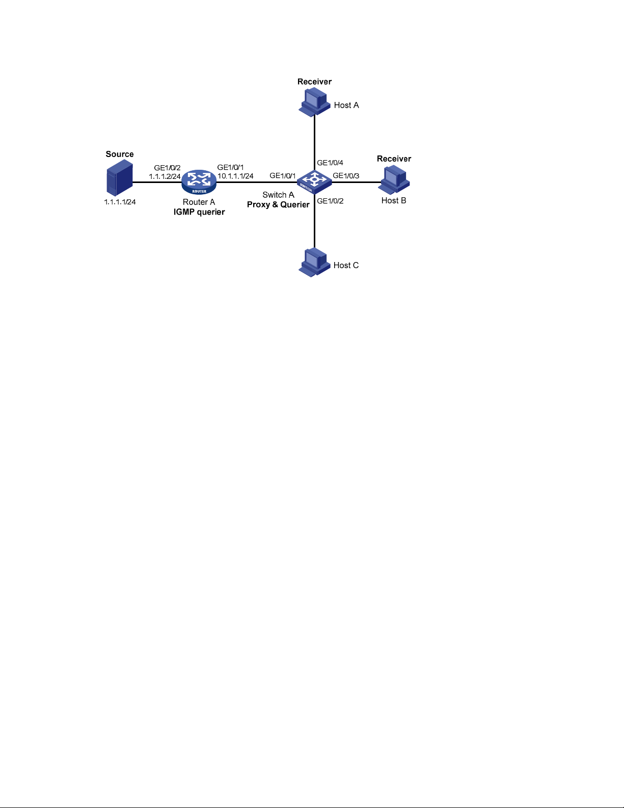
Figure 17 Network diagram for IGMP snooping proxying configuration
Configuration procedure
1. Configure IP addresses for interfaces
Configure an IP address and subnet mask for each interface according to Figure 17 (details not shown).
2. Configure Router A
# Enable IP multicast routing, enable PIM-DM on each interface, and enable IGMP on GigabitEthernet
1/0/1.
<RouterA> system-view
[RouterA] multicast routing-enable
[RouterA] interface gigabitethernet 1/0/1
[RouterA-GigabitEthernet1/0/1] igmp enable
[RouterA-GigabitEthernet1/0/1] pim dm
[RouterA-GigabitEthernet1/0/1] quit
[RouterA] interface gigabitethernet 1/0/2
[RouterA-GigabitEthernet1/0/2] pim dm
[RouterA-GigabitEthernet1/0/2] quit
3. Configure Switch A
# Enable IGMP snooping globally.
<SwitchA> system-view
[SwitchA] igmp-snooping
[SwitchA-igmp-snooping] quit
# Create VLAN 100, assign ports GigabitEthernet 1/0/1 through GigabitEthernet 1/0/4 to this VLAN,
and enable IGMP snooping and IGMP snooping proxying in the VLAN.
[SwitchA] vlan 100
[SwitchA-vlan100] port gigabitethernet 1/0/1 to gigabitethernet 1/0/4
[SwitchA-vlan100] igmp-snooping enable
[SwitchA-vlan100] igmp-snooping proxying enable
[SwitchA-vlan100] quit
45
Page 58

4.
Verify the configuration
After the configuration is completed, Host A and Host B send IGMP join messages for group 224.1.1.1.
Receiving the messages, Switch A sends a join message for the group out port GigabitEthernet 1/0/1—
a router port—to Router A.
Use the display igmp-snooping group command and the display igmp group command to display
information about IGMP snooping groups and IGMP multicast groups. For example:
# Display information about IGMP snooping groups on Switch A.
[SwitchA] display igmp-snooping group
Total 1 IP Group(s).
Total 1 IP Source(s).
Total 1 MAC Group(s).
Port flags: D-Dynamic port, S-Static port, C-Copy port
Subvlan flags: R-Real VLAN, C-Copy VLAN
Vlan(id):100.
Total 1 IP Group(s).
Total 1 IP Source(s).
Total 1 MAC Group(s).
Router port(s):total 1 port.
GE1/0/1 (D) ( 00:01:23 )
IP group(s):the following ip group(s) match to one mac group.
IP group address:224.1.1.1
(0.0.0.0, 224.1.1.1):
Host port(s):total 2 port.
GE1/0/3 (D)
GE1/0/4 (D)
MAC group(s):
MAC group address:0100-5e01-0101
Host port(s):total 2 port.
GE1/0/3
GE1/0/4
# Display information about IGMP multicast groups on Router A.
[RouterA] display igmp group
Total 1 IGMP Group(s).
Interface group report information of VPN-Instance: public net
GigabitEthernet1/0/1(10.1.1.1):
Total 1 IGMP Group reported
Group Address Last Reporter Uptime Expires
224.1.1.1 0.0.0.0 00:00:06 00:02:04
When Host A leaves the multicast group, it sends an IGMP leave message to Switch A. Receiving the
message, Switch A removes port GigabitEthernet 1/0/3 from the member port list of the forwarding
entry for the group; however, it does not remove the group or forward the leave message to Router A
because Host B is still in the group. Use the display igmp-snooping group command to display
information about IGMP snooping groups. For example:
# Display information about IGMP snooping groups on Switch A.
[SwitchA] display igmp-snooping group
Total 1 IP Group(s).
46
Page 59

Total 1 IP Source(s).
Total 1 MAC Group(s).
Port flags: D-Dynamic port, S-Static port, C-Copy port
Subvlan flags: R-Real VLAN, C-Copy VLAN
Vlan(id):100.
Total 1 IP Group(s).
Total 1 IP Source(s).
Total 1 MAC Group(s).
Router port(s):total 1 port.
GE1/0/1 (D) ( 00:01:23 )
IP group(s):the following ip group(s) match to one mac group.
IP group address:224.1.1.1
(0.0.0.0, 224.1.1.1):
Host port(s):total 1 port.
GE1/0/4 (D)
MAC group(s):
MAC group address:0100-5e01-0101
Host port(s):total 1 port.
GE1/0/4
Multicast source and user control policy configuration example
Network requirements
• As shown in Figure 18, Switch A is a Layer-3 switch. It connects to multicast sources 1 and 2 and
through VLAN-interface 101 and VLAN-interface 102 respectively. It connects to the RADIUS server
through VLAN-interface 103 and to Layer-2 switch B through VLAN-interface 104.
• Switch A runs IGMPv2 and Switch B runs IGMPv2 snooping. Multicast sources and hosts run
802.1X client.
• A multicast source control policy is configured on Switch A to block multicast flows from Source 2
to 224.1.1.1.
• A multicast user control policy is configured on Switch B so that Host A can join or leave only
multicast group 224.1.1.1.
47
Page 60

Figure 18 Network diagram for multicast source/user control policy configuration
Source 2
2.1.1.1/24
GE1/0/2
Vlan-int102
2.1.1.2/24
Vlan-int103
Configuration procedures
1. Configure IP addresses for interfaces
GE1/0/3
3.1.1.2/24
Source 1
1.1.1.1/24
GE1/0/1
Vlan-int101
1.1.1.2/24
GE1/0/4
Vlan-int104
4.1.1.1/24
Switch A
RADIUS server
3.1.1.1/24
GE1/0/1
Switch B
GE1/0/2
Host B
Receiver
GE1/0/3
Host A
Configure an IP address and subnet mask for each interface according to Figure 18 (details not shown).
2. Configure Switch A
# Create VLAN 101 through VLAN 104 and assign GigabitEthernet 1/0/1 through GigabitEthernet
1/0/4 to the four VLANs respectively.
<SwitchA> system-view
[SwitchA] vlan 101
[SwitchA-vlan101] port gigabitethernet 1/0/1
[SwitchA-vlan101] quit
[SwitchA] vlan 102
[SwitchA-vlan102] port gigabitethernet 1/0/2
[SwitchA-vlan102] quit
[SwitchA] vlan 103
[SwitchA-vlan103] port gigabitethernet 1/0/3
[SwitchA-vlan103] quit
[SwitchA] vlan 104
[SwitchA-vlan104] port gigabitethernet 1/0/4
[SwitchA-vlan104] quit
# Enable IP multicast routing. Enable PIM-DM on VLAN-interface 101, VLAN-interface 102 and VLANinterface 104, and enable IGMP on VLAN-interface 104.
[SwitchA] multicast routing-enable
[SwitchA] interface vlan-interface 101
[SwitchA-Vlan-interface101] pim dm
[SwitchA-Vlan-interface101] quit
[SwitchA] interface vlan-interface 102
[SwitchA-Vlan-interface102] pim dm
[SwitchA-Vlan-interface102] quit
48
Page 61

W
[SwitchA] interface vlan-interface 104
[SwitchA-Vlan-interface104] pim dm
[SwitchA-Vlan-interface104] igmp enable
[SwitchA-Vlan-interface104] quit
# Create QoS policy policy1 to block multicast flows from Source 2 to 224.1.1.1.
[SwitchA] acl number 3001
[SwitchA-acl-adv-3001] rule permit udp source 2.1.1.1 0 destination 224.1.1.1 0
[SwitchA-acl-adv-3001] quit
CAUTION:
hen configuring a multicast source control policy, you need to apply an advanced ACL to match both
the multicast source address and destination address. Otherwise, multicast packets expected to be
filtered out will still be forwarded.
[SwitchA] traffic classifier classifier1
[SwitchA-classifier-classifier1] if-match acl 3001
[SwitchA-classifier-classifier1] quit
CAUTION:
Do not reference any IPv6 ACL after an IPv4 ACL is referenced in classifier view. Otherwise, match
errors will occur.
[SwitchA] traffic behavior behavior1
[SwitchA-behavior-behavior1] filter deny
[SwitchA-behavior-behavior1] quit
[SwitchA] qos policy policy1
[SwitchA-qospolicy-policy1] classifier classifier1 behavior behavior1
[SwitchA-qospolicy-policy1] quit
# Create user profile profile1, apply QoS policy policy1 to the inbound direction in user profile view,
and enable the user profile.
[SwitchA] user-profile profile1
[SwitchA-user-profile-profile1] qos apply policy policy1 inbound
[SwitchA-user-profile-profile1] quit
[SwitchA] user-profile profile1 enable
# Create RADIUS scheme scheme1; set the service type for the RADIUS server to extended; specify the IP
addresses of the primary authentication/authorization server and accounting server as 3.1.1.1; set the
shared keys to 123321; specify that no domain name is carried in a username sent to the RADIUS
server.
[SwitchA] radius scheme scheme1
[SwitchA-radius-scheme1] server-type extended
[SwitchA-radius-scheme1] primary authentication 3.1.1.1
[SwitchA-radius-scheme1] key authentication 123321
[SwitchA-radius-scheme1] primary accounting 3.1.1.1
[SwitchA-radius-scheme1] key accounting 123321
[SwitchA-radius-scheme1] user-name-format without-domain
[SwitchA-radius-scheme1] quit
49
Page 62

# Create ISP domain domain1; reference scheme1 for the authentication, authorization, and accounting
of LAN users; specify domain1 as the default ISP domain.
[SwitchA] domain domain1
[SwitchA-isp-domian1] authentication lan-access radius-scheme scheme1
[SwitchA-isp-domian1] authorization lan-access radius-scheme scheme1
[SwitchA-isp-domian1] accounting lan-access radius-scheme scheme1
[SwitchA-isp-domian1] quit
[SwitchA] domain default enable domain1
# Globally enable 802.1X and then enable it on GigabitEthernet 1/0/1 and GigabitEthernet 1/0/2
respectively.
[SwitchA] dot1x
[SwitchA] interface gigabitethernet 1/0/1
[SwitchA-GigabitEthernet1/0/1] dot1x
[SwitchA-GigabitEthernet1/0/1] quit
[SwitchA] interface gigabitethernet 1/0/2
[SwitchA-GigabitEthernet1/0/2] dot1x
[SwitchA-GigabitEthernet1/0/2] quit
3. Configure Switch B
# Globally enable IGMP snooping.
<SwitchB> system-view
[SwitchB] igmp-snooping
[SwitchB-igmp-snooping] quit
# Create VLAN 100, assign GigabitEthernet 1/0/1 through GigabitEthernet 1/0/3 to this VLAN, and
enable IGMP snooping in this VLAN.
[SwitchB] vlan 100
[SwitchB-vlan100] port gigabitethernet 1/0/1 to gigabitethernet 1/0/3
[SwitchB-vlan100] igmp-snooping enable
[SwitchB-vlan100] quit
# Create a user profile profile2 to allow users to join or leave only one multicast group, 224.1.1.1.
Then, enable the user profile.
[SwitchB] acl number 2001
[SwitchB-acl-basic-2001] rule permit source 224.1.1.1 0
[SwitchB-acl-basic-2001] quit
[SwitchB] user-profile profile2
[SwitchB-user-profile-profile2] igmp-snooping access-policy 2001
[SwitchB-user-profile-profile2] quit
[SwitchB] user-profile profile2 enable
# Create a RADIUS scheme scheme2; set the service type for the RADIUS server to extended; specify the
IP addresses of the primary authentication/authorization server and accounting server as 3.1.1.1; set
the shared keys to 321123; specify that a username sent to the RADIUS server carry no domain name.
[SwitchB] radius scheme scheme2
[SwitchB-radius-scheme2] server-type extended
[SwitchB-radius-scheme2] primary authentication 3.1.1.1
[SwitchB-radius-scheme2] key authentication 321123
[SwitchB-radius-scheme2] primary accounting 3.1.1.1
[SwitchB-radius-scheme2] key accounting 321123
50
Page 63

[SwitchB-radius-scheme2] user-name-format without-domain
[SwitchB-radius-scheme2] quit
# Create an ISP domain domain2; reference scheme2 for the authentication, authorization, and
accounting of LAN users; specify domain2 as the default ISP domain.
[SwitchB] domain domain2
[SwitchB-isp-domian2] authentication lan-access radius-scheme scheme2
[SwitchB-isp-domian2] authorization lan-access radius-scheme scheme2
[SwitchB-isp-domian2] accounting lan-access radius-scheme scheme2
[SwitchB-isp-domian2] quit
[SwitchB] domain default enable domain2
# Globally enable 802.1X and then enable it on GigabitEthernet 1/0/2 and GigabitEthernet 1/0/3
respectively.
[SwitchB] dot1x
[SwitchB] interface gigabitethernet 1/0/2
[SwitchB-GigabitEthernet1/0/2] dot1x
[SwitchB-GigabitEthernet1/0/2] quit
[SwitchB] interface gigabitethernet 1/0/3
[SwitchB-GigabitEthernet1/0/3] dot1x
[SwitchB-GigabitEthernet1/0/3] quit
4. Configure the RADIUS server
On the RADIUS server, configure the parameters related to Switch A and Switch B. For more
information, see the configuration guide of the RADIUS server.
5. Verify the configuration
After the configurations, the two multicast sources and hosts initiate 802.1X authentication. After passing
authentication, Source 1 sends multicast flows to 224.1.1.1 and Source 2 sends multicast flows to
224.1.1.2; Host A sends messages to join multicast groups 224.1.1.1 and 224.1.1.2. Use the display
igmp-snooping group command to display information about IGMP snooping groups. For example:
# Display the information of the IGMP snooping groups in VLAN 100 on Switch B.
[SwitchB] display igmp-snooping group vlan 100 verbose
Total 1 IP Group(s).
Total 1 IP Source(s).
Total 1 MAC Group(s).
Port flags: D-Dynamic port, S-Static port, C-Copy port
Subvlan flags: R-Real VLAN, C-Copy VLAN
Vlan(id):100.
Total 1 IP Group(s).
Total 1 IP Source(s).
Total 1 MAC Group(s).
Router port(s):total 1 port.
GE1/0/1 (D) ( 00:01:30 )
IP group(s):the following ip group(s) match to one mac group.
IP group address:224.1.1.1
(0.0.0.0, 224.1.1.1):
Attribute: Host Port
Host port(s):total 1 port.
51
Page 64

GE1/0/3 (D) ( 00:04:10 )
MAC group(s):
MAC group address:0100-5e01-0101
Host port(s):total 1 port.
GE1/0/3
The output shows that GigabitEthernet 1/0/3 on Switch B has joined 224.1.1.1 but not 224.1.1.2.
Assume that Source 2 starts sending multicast traffic to 224.1.1.1. Use the display multicast forwarding-
table to display the multicast forwarding table information.
# Display the information about 224.1.1.1 in the multicast forwarding table on Switch A.
[SwitchA] display multicast forwarding-table 224.1.1.1
Multicast Forwarding Table of VPN-Instance: public net
Total 1 entry
Total 1 entry matched
00001. (1.1.1.1, 224.1.1.1)
MID: 0, Flags: 0x0:0
Uptime: 00:08:32, Timeout in: 00:03:26
Incoming interface: Vlan-interface101
List of 1 outgoing interfaces:
1: Vlan-interface104
Matched 19648 packets(20512512 bytes), Wrong If 0 packets
Forwarded 19648 packets(20512512 bytes)
The output shows that Switch A maintains a multicast forwarding entry for multicast packets from Source
1 to 224.1.1.1. No forwarding entry exists to forward packets from Source 2 to 224.1.1.1, which
indicates that multicast packets from Source 2 are blocked.
Troubleshooting IGMP snooping configuration
Layer 2 multicast forwarding cannot function
Symptom
Layer 2 multicast forwarding cannot function.
Analysis
IGMP snooping is not enabled.
Solution
1. Use the display current-configuration command to display the running status of IGMP snooping.
2. If IGMP snooping is not enabled, use the igmp-snooping command to enable IGMP snooping
globally, and then use the igmp-snooping enable command to enable IGMP snooping in VLAN
view.
3. If IGMP snooping is disabled only for the corresponding VLAN, use the igmp-snooping enable
command in VLAN view to enable IGMP snooping in the corresponding VLAN.
52
Page 65

Configured multicast group policy fails to take effect
Symptom
Although a multicast group policy has been configured to allow hosts to join specific multicast groups,
the hosts can still receive multicast data addressed to other multicast groups.
Analysis
• The ACL rule is incorrectly configured.
• The multicast group policy is not correctly applied.
• The function of dropping unknown multicast data is not enabled, so unknown multicast data is
flooded.
Solution
1. Use the display acl command to evaluate the configured ACL rule. Make sure that the ACL rule
conforms to the multicast group policy to be implemented.
2. Use the display this command in IGMP snooping view or in the corresponding interface view to
determine whether the correct multicast group policy has been applied. If not, use the group-policy
or igmp-snooping group-policy command to apply the correct multicast group policy.
3. Use the display current-configuration command to determine whether the function of dropping
unknown multicast data is enabled. If not, use the igmp-snooping drop-unknown command to
enable the function of dropping unknown multicast data.
Appendix (available only on the A5500 EI)
Processing of multicast protocol messages
With Layer 3 multicast routing enabled, an IGMP snooping–enabled switch processes multicast protocol
messages differently under different conditions, as follows:
1. If only IGMP is enabled on the switch, or if both IGMP and PIM are enabled on the switch, the
switch does the following:
{ Maintains dynamic member ports or dynamic router ports according to IGMP packets
{ Maintains dynamic router ports according to PIM hello packets
2. If only PIM is enabled on the switch, the following occur:
{ The switch broadcasts IGMP messages as unknown messages in the VLAN.
{ After receiving a PIM hello message, the switch maintains the corresponding dynamic router
port.
3. If IGMP is disabled on the switch, one of the following occurs:
{ If PIM is disabled, the switch deletes all its dynamic member ports and dynamic router ports.
{ If PIM is enabled, the switch deletes only its dynamic member ports but not its dynamic router
ports.
NOTE:
On a switch with Layer-3 multicast routing enabled, use the display igmp group port-info command to
display Layer-2 port information. For more information about this command, see the
Command Reference
.
53
IP Multicast
Page 66

4. If PIM is disabled on the switch, one of the following occurs:
{ If IGMP is disabled, the switch deletes all its dynamic router ports.
{ If IGMP is enabled, the switch maintains all its dynamic member ports and dynamic router
ports.
54
Page 67

Multicast VLAN configuration
Multicast VLAN overview
In the traditional multicast programs-on-demand mode shown in Figure 19, when hosts—Host A, Host B,
and Host C—that belong to different VLANs require multicast programs-on-demand service, the Layer 3
device—Router A—must forward a separate copy of the multicast traffic in each user VLAN to the Layer
2 device—Switch A. This results in not only waste of network bandwidth but also extra burden on the
Layer 3 device.
Figure 19 Multicast transmission without multicast VLAN
The multicast VLAN feature configured on the Layer 2 switch is the solution to this issue. With the
multicast VLAN feature, the Layer 3 device must replicate the multicast traffic only in the multicast VLAN
instead of making a separate copy of the multicast traffic in each user VLAN. This saves network
bandwidth and lessens the burden on the Layer 3 device.
The multicast VLAN feature can be implemented by the following approaches: sub-VLAN-based multicast
VLAN and port-based multicast VLAN.
Sub-VLAN-based multicast VLAN
As shown in Figure 20, Host A, Host B, and Host C are in different user VLANs. On Switch A, configure
VLAN 10 as a multicast VLAN, configure all user VLANs as sub-VLANs of VLAN 10, and enable IGMP
snooping in the multicast VLAN.
55
Page 68

Figure 20 Sub-VLAN-based multicast VLAN
Multicast packets
Source
VLAN 10 (Multicast VLAN)
VLAN 2
VLAN 3
VLAN 4
Router A
IGMP querier
Switch A
VLAN 2
Receiver
Host A
VLAN 3
Receiver
Host B
VLAN 4
Receiver
Host C
After the configuration, IGMP snooping manages router ports in the multicast VLAN and member ports in
the sub-VLANs. When forwarding multicast data to Switch A, Router A sends only one copy of multicast
data to Switch A in the multicast VLAN, and Switch A distributes the data to the multicast VLAN’s subVLANs that contain receivers.
Port-based multicast VLAN
As shown in Figure 21, Host A, Host B, and Host C are in different user VLANs. All user ports—ports
with attached hosts—on Switch A are hybrid ports. On Switch A, configure VLAN 10 as a multicast
VLAN, assign all user ports to VLAN 10, and enable IGMP snooping in the multicast VLAN and all user
VLANs.
Figure 21 Port-based multicast VLAN
After the configuration, upon receiving an IGMP message on a user port, Switch A tags the message
with the multicast VLAN ID and relays it to the IGMP querier, so that IGMP snooping can uniformly
manage the router port and member ports in the multicast VLAN. When Router A forwards multicast
data to Switch A, it sends only one copy of multicast data to Switch A in the multicast VLAN, and Switch
A distributes the data to all member ports in the multicast VLAN.
56
Page 69

NOTE:
For more information about IGMP snooping, router ports, and member ports, see the chapter “IGMP
snooping configuration.”
For more information about VLAN tags, see the
Layer 2—LAN Switching Configuration Guide
Multicast VLAN configuration task list
Complete the following tasks to configure multicast VLAN:
Task Remarks
Configuring sub-VLAN-based multicast VLAN
Configuring port-based multicast
VLAN
NOTE:
If you have configured both sub-VLAN-based multicast VLAN and port-based multicast VLAN on a
device, the port-based multicast VLAN configuration is given preference.
Configuring user port attributes
Configuring multicast VLAN ports
Required
Use either approach.
Configuring sub-VLAN-based multicast VLAN
Configuration prerequisites
.
Before you configure sub-VLAN-based multicast VLAN, complete the following tasks:
• Create VLANs as required
• Enable IGMP snooping in the VLAN to be configured as a multicast VLAN
Configuring sub-VLAN-based multicast VLAN
In this approach, you configure a VLAN as a multicast VLAN and configure user VLANs as sub-VLANs of
the multicast VLAN.
Follow these steps to configure sub-VLAN-based multicast VLAN:
To do… Use the command… Remarks
Enter system view system-view —
Configure the specified VLAN as
a multicast VLAN and enter
multicast VLAN view
Configure the specified VLANs as
sub-VLANs of the multicast VLAN
multicast-vlan vlan-id
subvlan vlan-list
Required
Not a multicast VLAN by default
Required
By default, a multicast VLAN has
no sub-VLANs.
57
Page 70

NOTE:
You cannot configure multicast VLAN on a device with IP multicast routing enabled.
The VLAN to be configured as a multicast VLAN must exist.
The VLANs to be configured as sub-VLANs of the multicast VLAN must exist and must not be sub-
VLANs of any other multicast VLAN.
Configuring port-based multicast VLAN
When you configure port-based multicast VLAN, you must configure the attributes of each user port and
then assign the ports to the multicast VLAN.
NOTE:
A user port can be configured as a multicast VLAN port when if it is an Ethernet interface or Layer 2
aggregate interface.
In Ethernet interface view or Layer 2 aggregate interface view, configurations that you make are
effective only on the current interface. In port group view, configurations that you make are effective
on all ports in the current port group.
Configuration prerequisites
Before you configure port-based multicast VLAN, complete the following tasks:
• Create VLANs as required
• Enable IGMP snooping in the VLAN to be configured as a multicast VLAN
• Enable IGMP snooping in all user VLANs
Configuring user port attributes
Configure the user ports as hybrid ports that permit packets of the specified user VLAN to pass, and
configure the user VLAN to which the user ports belong as the default VLAN.
Configure the user ports to permit packets of the multicast VLAN to pass and untag the packets. After the
configuration, upon receiving multicast packets tagged with the multicast VLAN ID from the upstream
device, the Layer 2 device untags the multicast packets and forwards them to its downstream device.
Follow these steps to configure user port attributes:
To do... Use the command... Remarks
Enter system view system-view —
interface interface-type interface-
Enter interface view or port group
view
number
port-group { manual port-groupname | aggregation agg-id }
Required
Use either command
Configure the user port link type
as hybrid
port link-type hybrid
58
Required
Access by default
Page 71

To do... Use the command... Remarks
Specify the user VLAN that
comprises the current user ports
as the default VLAN
Configure the current user ports to
permit packets of the specified
multicast VLANs to pass and
untag the packets
port hybrid pvid vlan vlan-id
port hybrid vlan vlan-id-list
untagged
NOTE:
For more information about the port link-type, port hybrid pvid vlan, and port hybrid vlan
commands, see the
Layer 2—LAN Switching Command Reference
Configuring multicast VLAN ports
In this approach, you configure a VLAN as a multicast VLAN and assign user ports to it. You can do this
by either adding the user ports in the multicast VLAN or specifying the multicast VLAN on the user ports.
These two methods provide the same result.
Configuring multicast VLAN ports in multicast VLAN view
Follow these steps to configure multicast VLAN ports in multicast VLAN view:
To do... Use the command... Remarks
Required
VLAN 1 by default
Required
By default, a hybrid port permits
only packets of VLAN 1 to pass.
.
Enter system view
Configure the specified VLAN as a
multicast VLAN and enter multicast
VLAN view
Assign ports to the multicast VLAN port interface-list
system-view
multicast-vlan vlan-id
Configuring multicast VLAN ports in interface view or port group view
Follow these steps to configure multicast VLAN ports in interface view or port group view:
To do… Use this command… Remarks
Enter system view system-view —
Configure the specified VLAN as
a multicast VLAN and enter
multicast VLAN view
Return to system view quit —
Enter interface view or port group
view
multicast-vlan vlan-id
interface interface-type interface-
number
—
Required
Not a multicast VLAN by default
Required
By default, a multicast VLAN has
no ports.
Required
Not a multicast VLAN by default.
Required
Use either command.
59
Page 72

To do… Use this command… Remarks
port-group manual port-group-
name
Configure the current port as a
member port of the multicast
VLAN
NOTE:
You cannot configure multicast VLAN on a device with multicast routing enabled.
The VLAN to be configured as a multicast VLAN must exist.
A port can belong to only one multicast VLAN.
port multicast-vlan vlan-id
Required
By default, a user port does not
belong to any multicast VLAN.
Displaying and maintaining multicast VLAN
To do… Use the command… Remarks
Display information about a
multicast VLAN
display multicast-vlan [ vlan-id ] [
| { begin | exclude | include }
regular-expression ]
Available in any view
Multicast VLAN configuration examples
Sub-VLAN-based multicast VLAN configuration
Network requirements
• Router A connects to a multicast source through GigabitEthernet 1/0/1 and to Switch A, through
GigabitEthernet 1/0/2.
• IGMPv2 runs on Router A, and IGMPv2 snooping runs on Switch A. Router A is the IGMP querier.
• Switch A’s GigabitEthernet 1/0/1 belongs to VLAN 10, GigabitEthernet 1/0/2 through
GigabitEthernet 1/0/4 belong to VLAN 2 through VLAN 4 respectively, and Host A through Host
C are attached to GigabitEthernet 1/0/2 through GigabitEthernet 1/0/4 of Switch A respectively.
• The multicast source sends multicast data to multicast group 224.1.1.1. Host A, Host B, and Host C
are receivers of the multicast group.
• Configure the sub-VLAN-based multicast VLAN feature so that Router A just sends multicast data to
Switch A through the multicast VLAN and Switch A forwards the traffic to the receivers that belong
to different user VLANs.
60
Page 73
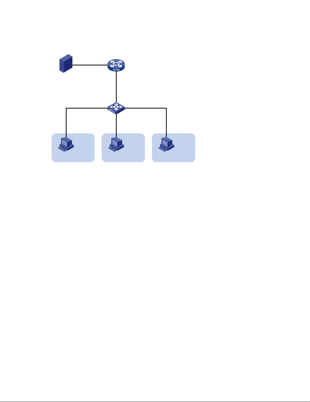
Network diagram
Figure 22 Network diagram for sub-VLAN-based multicast VLAN configuration
Source
1.1.1.1/24
Receiver
Host A
VLAN 2
Configuration procedure
1. Configure IP addresses
Configure an IP address and subnet mask for each interface according to Figure 22 (details not shown).
GE1/0/1
1.1.1.2/24
Switch A
GE1/0/2
IGMP querier
Router A
GE1/0/2
10.110.1.1/24
GE1/0/1
GE1/0/4
GE1/0/3
Receiver
Host B
VLAN 3
Receiver
VLAN 4
Host C
2. Configure Router A
# Enable IP multicast routing, enable PIM-DM on each interface and enable IGMP on the host-side
interface GigabitEthernet 1/0/2.
<RouterA> system-view
[RouterA] multicast routing-enable
[RouterA] interface gigabitethernet 1/0/1
[RouterA-GigabitEthernet1/0/1] pim dm
[RouterA-GigabitEthernet1/0/1] quit
[RouterA] interface gigabitethernet 1/0/2
[RouterA-GigabitEthernet1/0/2] pim dm
[RouterA-GigabitEthernet1/0/2] igmp enable
3. Configure Switch A
# Enable IGMP snooping globally.
<SwitchA> system-view
[SwitchA] igmp-snooping
[SwitchA-igmp-snooping] quit
# Create VLAN 2 and assign GigabitEthernet 1/0/2 to this VLAN.
[SwitchA] vlan 2
[SwitchA-vlan2] port gigabitethernet 1/0/2
[SwitchA-vlan2] quit
The configuration for VLAN 3 and VLAN 4 is similar to the configuration for VLAN 2.
61
Page 74

# Create VLAN 10, assign GigabitEthernet 1/0/1 to this VLAN and enable IGMP snooping in the
VLAN.
[SwitchA] vlan 10
[SwitchA-vlan10] port gigabitethernet 1/0/1
[SwitchA-vlan10] igmp-snooping enable
[SwitchA-vlan10] quit
# Configure VLAN 10 as a multicast VLAN and configure VLAN 2 through VLAN 4 as its sub-VLANs.
[SwitchA] multicast-vlan 10
[SwitchA-mvlan-10] subvlan 2 to 4
[SwitchA-mvlan-10] quit
4. Verify the configuration
# Display information about the multicast VLAN.
[SwitchA] display multicast-vlan
Total 1 multicast-vlan(s)
Multicast vlan 10
subvlan list:
vlan 2-4
port list:
no port
# View the IGMP snooping multicast group information on Switch A.
[SwitchA] display igmp-snooping group
Total 4 IP Group(s).
Total 4 IP Source(s).
Total 4 MAC Group(s).
Port flags: D-Dynamic port, S-Static port, C-Copy port
Subvlan flags: R-Real VLAN, C-Copy VLAN
Vlan(id):2.
Total 1 IP Group(s).
Total 1 IP Source(s).
Total 1 MAC Group(s).
Router port(s):total 0 port(s).
IP group(s):the following ip group(s) match to one mac group.
IP group address:224.1.1.1
(0.0.0.0, 224.1.1.1):
Host port(s):total 1 port(s).
GE1/0/2 (D)
MAC group(s):
MAC group address:0100-5e01-0101
Host port(s):total 1 port(s).
GE1/0/2
Vlan(id):3.
Total 1 IP Group(s).
Total 1 IP Source(s).
Total 1 MAC Group(s).
62
Page 75

Router port(s):total 0 port(s).
IP group(s):the following ip group(s) match to one mac group.
IP group address:224.1.1.1
(0.0.0.0, 224.1.1.1):
Host port(s):total 1 port(s).
GE1/0/3 (D)
MAC group(s):
MAC group address:0100-5e01-0101
Host port(s):total 1 port(s).
GE1/0/3
Vlan(id):4.
Total 1 IP Group(s).
Total 1 IP Source(s).
Total 1 MAC Group(s).
Router port(s):total 0 port(s).
IP group(s):the following ip group(s) match to one mac group.
IP group address:224.1.1.1
(0.0.0.0, 224.1.1.1):
Host port(s):total 1 port(s).
GE1/0/4 (D)
MAC group(s):
MAC group address:0100-5e01-0101
Host port(s):total 1 port(s).
GE1/0/4
Vlan(id):10.
Total 1 IP Group(s).
Total 1 IP Source(s).
Total 1 MAC Group(s).
Router port(s):total 1 port(s).
GE1/0/1 (D)
IP group(s):the following ip group(s) match to one mac group.
IP group address:224.1.1.1
(0.0.0.0, 224.1.1.1):
Host port(s):total 0 port(s).
MAC group(s):
MAC group address:0100-5e01-0101
Host port(s):total 0 port(s).
The outputs shows that IGMP snooping is maintaining the router port in the multicast VLAN—VLAN 10—
and the member ports in the sub-VLANs—VLAN 2 through VLAN 4.
Port-based multicast VLAN configuration
Network requirements
• As shown in Figure 23, Router A connects to a multicast source—Source—through GigabitEthernet
1/0/1, and to Switch A through GigabitEthernet 1/0/2.
63
Page 76

• IGMPv2 runs on Router A. IGMPv2 snooping runs on Switch A. Router A acts as the IGMP querier.
• Switch A’s GigabitEthernet 1/0/1 belongs to VLAN 10, GigabitEthernet 1/0/2 through
GigabitEthernet 1/0/4 belong to VLAN 2 through VLAN 4 respectively, and Host A through Host
C are attached to GigabitEthernet 1/0/2 through GigabitEthernet 1/0/4 of Switch A respectively.
• The multicast source sends multicast data to multicast group 224.1.1.1. Host A, Host B, and Host C
are receivers of the multicast group.
• Configure the port-based multicast VLAN feature so that Router A just sends multicast data to Switch
A through the multicast VLAN and Switch A forwards the multicast data to the receivers that belong
to different user VLANs.
Network diagram
Figure 23 Network diagram for port-based multicast VLAN configuration
Source
1.1.1.1/24
Receiver
Host A
VLAN 2
Configuration procedure
1. Configure IP addresses
Configure the IP address and subnet mask for each interface according to Figure 23 (details not shown).
GE1/0/1
1.1.1.2/24
Switch A
GE1/0/2
IGMP querier
Router A
GE1/0/2
10.110.1.1/24
GE1/0/1
GE1/0/4
GE1/0/3
Receiver
Host B
VLAN 3
Receiver
VLAN 4
Host C
2. Configure Router A
# Enable IP multicast routing, enable PIM-DM on each interface, and enable IGMP on the host-side
interface GigabitEthernet 1/0/2.
<RouterA> system-view
[RouterA] multicast routing-enable
[RouterA] interface gigabitethernet 1/0/1
[RouterA-GigabitEthernet1/0/1] pim dm
[RouterA-GigabitEthernet1/0/1] quit
[RouterA] interface gigabitethernet 1/0/2
[RouterA-GigabitEthernet1/0/2] pim dm
[RouterA-GigabitEthernet1/0/2] igmp enable
3. Configure Switch A
# Enable IGMP snooping globally.
64
Page 77

<SwitchA> system-view
[SwitchA] igmp-snooping
[SwitchA-igmp-snooping] quit
# Create VLAN 10, assign GigabitEthernet 1/0/1 to VLAN 10, and enable IGMP snooping in this
VLAN.
[SwitchA] vlan 10
[SwitchA-vlan10] port gigabitethernet 1/0/1
[SwitchA-vlan10] igmp-snooping enable
[SwitchA-vlan10] quit
# Create VLAN 2 and enable IGMP snooping in the VLAN.
[SwitchA] vlan 2
[SwitchA-vlan2] igmp-snooping enable
[SwitchA-vlan2] quit
The configuration for VLAN 3 and VLAN 4 is similar (details not shown).
# Configure GigabitEthernet 1/0/2 as a hybrid port. Configure VLAN 2 as the default VLAN. Configure
GigabitEthernet 1/0/2 to permit packets of VLAN 2 and VLAN 10 to pass and untag the packets when
forwarding them.
[SwitchA] interface gigabitethernet 1/0/2
[SwitchA-GigabitEthernet1/0/2] port link-type hybrid
[SwitchA-GigabitEthernet1/0/2] port hybrid pvid vlan 2
[SwitchA-GigabitEthernet1/0/2] port hybrid vlan 2 untagged
[SwitchA-GigabitEthernet1/0/2] port hybrid vlan 10 untagged
[SwitchA-GigabitEthernet1/0/2] quit
The configuration for GigabitEthernet 1/0/3 and GigabitEthernet 1/0/4 is similar (details not shown).
# Configure VLAN 10 as a multicast VLAN.
[SwitchA] multicast-vlan 10
# Assign GigabitEthernet 1/0/2 and GigabitEthernet 1/0/3 to VLAN 10.
[SwitchA-mvlan-10] port gigabitethernet 1/0/2 to gigabitethernet 1/0/3
[SwitchA-mvlan-10] quit
# Assign GigabitEthernet 1/0/4 to VLAN 10.
[SwitchA] interface gigabitethernet 1/0/4
[SwitchA-GigabitEthernet1/0/4] port multicast-vlan 10
[SwitchA-GigabitEthernet1/0/4] quit
4. Verify the configuration
# View the multicast VLAN information on Switch A.
[SwitchA] display multicast-vlan
Total 1 multicast-vlan(s)
Multicast vlan 10
subvlan list:
no subvlan
port list:
GE1/0/2 GE1/0/3 GE1/0/4
# View the IGMP snooping multicast group information on Switch A.
65
Page 78

[SwitchA] display igmp-snooping group
Total 1 IP Group(s).
Total 1 IP Source(s).
Total 1 MAC Group(s).
Port flags: D-Dynamic port, S-Static port, C-Copy port
Subvlan flags: R-Real VLAN, C-Copy VLAN
Vlan(id):10.
Total 1 IP Group(s).
Total 1 IP Source(s).
Total 1 MAC Group(s).
Router port(s):total 1 port(s).
GE1/0/1 (D)
IP group(s):the following ip group(s) match to one mac group.
IP group address:224.1.1.1
(0.0.0.0, 224.1.1.1):
Host port(s):total 3 port(s).
GE1/0/2 (D)
GE1/0/3 (D)
GE1/0/4 (D)
MAC group(s):
MAC group address:0100-5e01-0101
Host port(s):total 3 port(s).
GE1/0/2
GE1/0/3
GE1/0/4
The output shows that IGMP snooping is maintaining the router ports and member ports in VLAN 10.
66
Page 79

Multicast routing and forwarding configuration (available only on the A5500 EI)
NOTE:
router
The term
The interfaces in this document refer to Layer 3 interfaces in generic sense and Ethernet interfaces that
operate in route mode. For more information about the operating mode of the Ethernet interfaces, see
the
Layer 2—LAN Switching Configuration Guide.
Multicast routing and forwarding overview
Introduction to multicast routing and forwarding
in this document refers to both routers and Layer 3 switches.
In multicast implementations, the following types of tables implement multicast routing and forwarding:
• Multicast routing table of a multicast routing protocol—Each multicast routing protocol has its own
multicast routing table, such as PIM routing table.
• General multicast routing table—The multicast routing information of different multicast routing
protocols forms a general multicast routing table.
• Multicast forwarding table—The multicast forwarding table guides the forwarding of multicast
packets.
A multicast routing table consists of a set of (S, G) entries. Each entry indicates the routing information
for delivering multicast data from a multicast source to a multicast group. If a router supports multiple
multicast protocols, its multicast routing table includes routes generated by multiple protocols. The router
chooses the optimal route from the multicast routing table based on the configured multicast routing and
forwarding policy and adds the route entry to its multicast forwarding table.
RPF check mechanism
A multicast routing protocol relies on the existing unicast routes, MBGP routes, or multicast static routes
in creating multicast routing entries. When creating multicast routing table entries, a multicast routing
protocol uses the RPF check mechanism to ensure multicast data delivery along the correct paths. In
addition, the RPF check mechanism also helps avoid data loops.
RPF check process
An RPF check is based on one of the following routing tables:
• Unicast routing table—Contains the shortest path to each destination subnet
• MBGP routing table—Contains multicast routing information
• Multicast static routing table—Contains the RPF routing information defined by the user through
static configuration
67
Page 80

g
When performing an RPF check, a router searches its unicast routing table, MBGP routing table, and
multicast static routing table at the same time. The following describes the specific process:
1. The router first chooses an optimal route from each of the unicast routing table, the MBGP routing
table, and the multicast static routing table:
{ The router automatically chooses an optimal unicast route by searching its unicast routing table
and using the IP address of the packet source as the destination address. The outgoing interface
in the corresponding routing entry is the RPF interface and the next hop is the RPF neighbor. The
router considers the path along which the packet from the RPF neighbor arrived on the RPF
interface to be the shortest path that leads back to the source.
{ The router automatically chooses an optimal MBGP route by searching its MBGP routing table,
using the IP address of the packet source as the destination address. The outgoing interface in
the corresponding routing entry is the RPF interface, and the next hop is the RPF neighbor.
{ The router automatically chooses an optimal multicast static route by searching its multicast
static routing table, using the IP address of the packet source as the destination address. The
corresponding routing entry explicitly defines the RPF interface and the RPF neighbor.
2. The router selects one of these optimal routes as the RPF route. The following describes the selection
process:
{ If configured to use the longest match principle, the router selects the longest match route from
the three optimal routes. If the three routes have the same mask, the router selects the route with
the highest priority. If the three routes have the same priority, the router selects the RPF route
according to the sequence of multicast static route, MBGP route, and unicast route.
{ If not configured to use the longest match principle, the router selects the route with the highest
priority. If the three routes have the same priority, the router selects the RPF route according to
the sequence of multicast static route, MBGP route, and unicast route.
NOTE:
packet source
The
means different things in different situations:
For a packet traveling along the shortest path tree (SPT) from the multicast source to the receivers or
the rendezvous point (RP), the packet source for RPF check is the multicast source.
For a packet traveling along the rendezvous point tree (RPT) from the RP to the receivers, or alon
source-side RPT from the multicast source to the RP, the packet source for RPF check is the RP.
For a bootstrap message from the bootstrap router (BSR), the packet source for RPF check is the BSR.
For more information about the concepts of SPT, RPT, source-side RPT, RPT, and BSR, see the chapter
“PIM configuration.”
Implementation of RPF check in multicast
Implementing an RPF check on each received multicast data packet would be a big burden to the router.
The use of a multicast forwarding table is the solution to this issue. When creating a multicast routing
entry and a multicast forwarding entry for a multicast packet, the router sets the RPF interface of the
packet as the incoming interface of the (S, G) entry. After receiving an (S, G) multicast packet, the router
first searches its multicast forwarding table:
the
1. If the corresponding (S, G) entry does not exist in the multicast forwarding table, the packet
undergoes an RPF check. The router creates a multicast routing entry based on the relevant routing
information and adds the entry into the multicast forwarding table, with the RPF interface as the
incoming interface.
68
Page 81

{ If the interface that received the packet is the RPF interface, the RPF check succeeds, and the
router forwards the packet to all the outgoing interfaces.
{ If the interface that received the packet is not the RPF interface, the RPF check fails, and the
router discards the packet.
2. If the corresponding (S, G) entry exists, and the interface that received the packet is the incoming
interface, the router forwards the packet to all the outgoing interfaces.
3. If the corresponding (S, G) entry exists, but the interface that received the packet is not the
incoming interface in the multicast forwarding table, the multicast packet undergoes an RPF check.
{ If the RPF interface is the incoming interface of the (S, G) entry, it indicates that the (S, G) entry
is correct but the packet arrived from a wrong path. The packet will be discarded.
{ If the RPF interface is not the incoming interface, it indicates that the (S, G) entry has expired,
and the router replaces the incoming interface with the RPF interface. If the interface on which
the packet arrived is the RPF interface, the router forwards the packet to all the outgoing
interfaces. Otherwise, it discards the packet.
Assume that unicast routes are available in the network, MBGP is not configured, and no multicast static
routes have been configured on Router C, as shown in Figure 24. Mu
lticast packets travel along the SPT
from the multicast source to the receivers. The multicast forwarding table on Router C contains the (S, G)
entry, with VLAN-interface 20 as the incoming interface.
Figure 24 RPF check process
• When a multicast packet arrives on interface VLAN-interface 20 of Router C, because the interface
is the incoming interface of the (S, G) entry, the router forwards the packet to all outgoing
interfaces.
• When a multicast packet arrives on interface VLAN-interface 10 of Router C, because the interface
is not the incoming interface of the (S, G) entry, the router performs an RPF check on the packet.
The router searches its unicast routing table and finds that the outgoing interface to Source—the RPF
interface—is VLAN-interface 20. It indicates the (S, G) entry is correct, and the packet arrived
along a wrong path. The RPF check fails, and the packet is discarded.
Multicast static routes
A multicast static route is an important basis for RPF check. Depending on the application environment,
configuring a multicast static route helps change an RFP route and create an RPF route.
69
Page 82
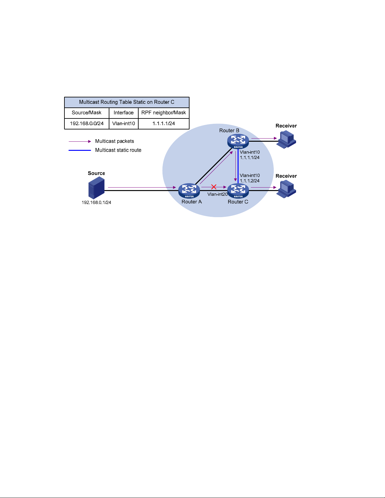
RPF route change
The topology structure of a multicast network is the same as that of a unicast network, and multicast
traffic follows the same transmission path that unicast traffic does. You can configure a multicast static
route for a given multicast source to change the RPF route to create a transmission path for multicast
traffic different from the transmission path for unicast traffic.
Figure 25 Changing an RPF route
As shown in Figure 25, when no multicast static route is configured, Router C’s RPF neighbor on the path
back to Source is Router A, and the multicast information from Source travels along the path from Router
A to Router C, which is the unicast route between the two routers. When a multicast static route is
configured on Router C and Router B is configured as Router C’s RPF neighbor on the path back to
Source, the multicast information from Source travels from Router A to Router B and then to Router C.
RPF route creation
When a unicast route is blocked, multicast traffic forwarding might be stopped because of a lack of an
RPF route. You can configure a multicast static route for a given multicast source to create an RPF route
so that a multicast routing entry is created to guide multicast traffic forwarding regardless of whether a
unicast route is available.
70
Page 83

Figure 26 Creating an RPF route
As shown in Figure 26, the RIP domain and the OSPF domain are unicast isolated from each other.
When no multicast static route is configured, the hosts—Receivers—in the OSPF domain cannot receive
the multicast packets that the multicast source sent in the RIP domain. After you configure a multicast
static route on Router C and Router D, specifying Router B as the RPF neighbor of Router C and Router C
as the RPF neighbor of Router D, the receivers can receive multicast data that the multicast source sent.
NOTE:
A multicast static route only affects RPF check, but it cannot guide multicast forwarding. A multicast
static route is also called an “RPF static route.”
A multicast static route is effective only on the multicast router on which it is configured, and will not
be advertised throughout the network or redistributed to other routers.
Multicast traceroute
You can use the multicast traceroute utility to trace the path of a multicast stream from the first-hop router
to the last-hop router.
Concepts in multicast traceroute
• Last-hop router—If one of the interfaces of a router connects to the subnet that contains the given
destination address, and if the router can forward multicast streams from the given multicast source
to that subnet, that router is called the “last-hop router.”
• First-hop router—The router that directly connects to the multicast source is called the “first-hop
router.”
• Querier—The router that is requesting the multicast traceroute is called the “querier.”
Introduction to multicast traceroute packets
A multicast traceroute packet is a special IGMP packet that is different from common IGMP packets in
that its IGMP Type field is set to 0x1F or 0x1E and its destination IP address is a unicast address.
Multicast traceroute packets include the following types:
71
Page 84

• Query—Its IGMP Type field is set to 0x1F
• Request—Its IGMP Type field is set to 0x1F
• Response—Its IGMP Type field is set to 0x1E
Process of multicast traceroute
1. The querier sends a query to the last-hop router.
2. After receiving the query, the last-hop router turns the query packet into a request packet by adding
a response data block—which contains its interface addresses and packet statistics—to the end of
the packet. It then forwards the request packet through unicast to the previous hop for the given
multicast source and group.
3. From the last-hop router to the multicast source, each hop adds a response data block to the end of
the request packet and forwards it through unicast to the previous hop.
4. When the first-hop router receives the request packet, it changes the packet type to indicate a
response packet. Then, it sends the completed packet through unicast to the querier.
Configuration task list
Complete these tasks to configure multicast routing and forwarding:
Task Remarks
Enabling IP multicast routing Optional
Configuring multicast static routes Optional
Configuring a multicast routing
policy
Configuring multicast routing and
forwarding
CAUTION:
Configuring a multicast forwarding
range
Configuring the multicast
forwarding table size
Tracing a multicast path Optional
IP multicast does not support secondary IP address segments. Namely, multicast can be routed and
forwarded only through primary IP addresses even if secondary addresses are configured on
interfaces. For more information about primary and secondary IP addresses, see the
Services Configuration Guide
.
Enabling IP multicast routing
Before you configure any Layer 3 multicast functionality, you must enable IP multicast routing.
Optional
Optional
Optional
Layer 3—IP
Enabling IP multicast routing for the public network
Follow these steps to enable IP multicast routing for the public network:
To do... Use the command... Remarks
Enter system view
system-view —
72
Page 85

To do... Use the command... Remarks
Enable IP multicast routing
multicast routing-enable
Enabling IP multicast routing in a VPN instance
Follow these steps to enable IP multicast routing in a VPN instance:
To do… Use the command… Remarks
Enter system view system-view —
Create a VPN instance and
enter VPN instance view
Configure a route distinguisher
(RD) for the VPN instance
Enable IP multicast routing multicast routing-enable
NOTE:
For information about the ip vpn-instance and route-distinguisher commands, see the
Reference
.
ip vpn-instance vpn-instance-name —
route-distinguisher route-distinguisher
Required
Disabled by default
Required
No RD is configured by
default.
Required
Disabled by default
MPLS Command
Configuring multicast routing and forwarding
Configuration prerequisites
Before you configure multicast routing and forwarding, complete the following tasks:
• Configure a unicast routing protocol so that all devices in the domain are interoperable at the
network layer
• Enable PIM—PIM-DM or PIM-SM
• Determine the maximum number of downstream nodes for a single multicast forwarding table entry
• Determine the maximum number of entries in the multicast forwarding table
Configuring multicast static routes
You can configure a multicast static route for a given multicast source to specify an RPF interface or an
RPF neighbor for multicast traffic from that source.
Follow these steps to configure a multicast static route:
To do... Use the command... Remarks
Enter system view
system-view —
73
Page 86

W
To do... Use the command... Remarks
ip rpf-route-static [ vpn-instance vpn-instance-name ]
Configure a multicast
static route
Delete multicast static
routes
CAUTION:
source-address { mask | mask-length } [ protocol [
process-id ] ] [ route-policy policy-name ] { rpf-nbraddress | interface-type interface-number } [
preference preference ] [ order order-number ]
delete ip rpf-route-static [ vpn-instance vpn-instance-
name ]
hen you configure a multicast static route, do not specify an RPF neighbor by providing the type and
the number of the interface that connects to the RPF neighbor if the interface type of the RPF neighbor is
Ethernet, Loopback, RPR, or VLAN-interface. Instead, specify such an RPF neighbor only by its
address—
rpf-nbr-address.
Configuring a multicast routing policy
You can configure the router to determine the RPF route based on the longest match principle. For more
information about RPF route selection, see “RPF check process.”
You
can configure per-source or per-source-and-group load splitting to optimize the traffic delivery when
multiple data flows are handled.
Required
No multicast static route
configured by default.
Optional
Configuring a multicast routing policy for the public network
Follow these steps to configure a multicast routing policy for the public network:
To do... Use the command... Remarks
Enter system view
Configure the device to select the
RPF route based on the longest
match
Configure multicast load splitting
system-view —
multicast longest-match
multicast load-splitting { source |
source-group }
Configuring a multicast routing policy in a VPN instance
Follow these steps to configure a multicast routing policy in a VPN instance:
To do... Use the command... Remarks
Enter system view system-view —
Enter VPN instance view ip vpn-instance vpn-instance-name —
Configure the device to select
the RPF route based on the
longest match
multicast longest-match
Required
The route with the highest priority
is selected as the RPF route by
default
Optional
Disabled by default
Required
The route with the highest
priority is selected as the RPF
route by default
74
Page 87

To do... Use the command... Remarks
Configure multicast load splitting
multicast load-splitting { source |
source-group }
Configuring a multicast forwarding range
Multicast packets do not travel without a boundary in a network. The multicast data corresponding to
each multicast group must be transmitted within a definite scope. You can define a multicast forwarding
range by one of the following methods:
• Specifying boundary interfaces, which form a closed multicast forwarding area, or
• Setting the minimum time to live (TTL) value required for a multicast packet to be forwarded.
NOTE:
Setting the minimum TTL is not supported on HP A5500 EI Switch Series.
You can configure a forwarding boundary specific to a particular multicast group on all interfaces that
support multicast forwarding. A multicast forwarding boundary sets the boundary condition for the
multicast groups in the specified range. If the destination address of a multicast packet matches the set
boundary condition, the packet will not be forwarded. After you configure a multicast boundary on an
interface, the interface can no longer forward multicast packets—including packets sent from the local
device—or receive multicast packets.
Optional
Disabled by default
Follow these steps to configure a multicast forwarding range:
To do... Use the command... Remarks
Enter system view system-view —
Enter interface view
Configure a multicast forwarding
boundary
interface interface-type interfacenumber
multicast boundary group-address {
mask | mask-length }
—
Required
No forwarding boundary by
default
Configuring the multicast forwarding table size
The switch maintains the corresponding forwarding entry for each multicast packet that it receives.
Excessive multicast routing entries, however, can exhaust the switch’s memory and cause lower
performance. You can set a limit on the number of entries in the multicast forwarding table based on the
networking situation and the performance requirements. If the configured maximum number of multicast
forwarding table entries is smaller than the current value, the forwarding entries in excess are not
deleted immediately. Instead, the multicast routing protocol that runs on the switch deletes them. The
switch no longer adds new multicast forwarding entries until the number of existing multicast forwarding
entries comes down below the configured value.
When forwarding multicast traffic, the switch replicates a copy of the multicast traffic for each
downstream node and forwards the traffic. Therefore, each of these downstream nodes forms a branch
of the multicast distribution tree. You can configure the maximum number of downstream nodes—
namely, the maximum number of outgoing interfaces—for a single entry in the multicast forwarding table
to lessen the burden on the switch for replicating multicast traffic. If the configured maximum number of
75
Page 88

downstream nodes for a single multicast forwarding entry is smaller than the current number, the
downstream nodes in excess are not deleted immediately. Instead, the multicast routing protocol that
runs on the switch deletes them. The switch no longer adds new multicast forwarding entries for newly
added downstream nodes until the number of existing downstream nodes comes down below the
configured value.
Configuring the multicast forwarding table size for the public network
Follow these steps to configure the multicast forwarding table size for the public network:
To do... Use the command... Remarks
Enter system view system-view —
Configure the maximum number
of entries in the multicast
forwarding table
Configure the maximum number
of downstream nodes for a single
multicast forwarding entry
multicast forwarding-table route-
limit limit
multicast forwarding-table
downstream-limit limit
Configuring the multicast forwarding table size in a VPN instance
Follow these steps to configure the multicast forwarding table size in a VPN instance:
To do... Use the command... Remarks
Enter system view system-view —
Enter VPN instance view ip vpn-instance vpn-instance-name —
Configure the maximum number
of entries in the multicast
forwarding table
Configure the maximum number
of downstream nodes for a single
route in the multicast forwarding
table
multicast forwarding-table route-
limit limit
multicast forwarding-table
downstream-limit limit
Optional
2000 by default.
Optional
128 by default.
Optional
2000 by default.
Optional
128 by default.
Tracing a multicast path
You can run the mtracert command to trace the path down which the multicast traffic flows from a given
first-hop router to the last-hop router.
To do… Use the command… Remarks
Trace a multicast path
mtracert source-address [ [ last-
hop-router-address ] groupaddress ]
76
Required
Available in any view
Page 89

Displaying and maintaining multicast routing and forwarding
To do... Use the command... Remarks
display multicast [ all-instance | vpn-instance vpn-
Display multicast boundary
information
Display multicast forwarding
table information
Display the DF information of
the multicast forwarding table
instance-name ] boundary [ group-address [ mask | masklength ] ] [ interface interface-type interface-number ] [ | {
begin | exclude | include } regular-expression ]
display multicast [ all-instance | vpn-instance vpn-
instance-name ] forwarding-table [ source-address [ mask
{ mask | mask-length } ] | group-address [ mask { mask |
mask-length } ] | incoming-interface { interface-type
interface-number | register } | outgoing-interface { {
exclude | include | match } { interface-type interface-
number | register } } | statistics | slot slot-number ] * [
port-info ] [ | { begin | exclude | include } regularexpression ]
display multicast [ all-instance | vpn-instance vpn-
instance-name ] forwarding-table df-info [ rp-address ] [
slot slot-number ] [ | { begin | exclude | include } regular-
expression ]
Available in
any view
Available in
any view
Available in
any view
Display multicast routing table
information
Display information of the
multicast static routing table
Display RPF route information
of the specified multicast source
Clear forwarding entries from
the multicast forwarding table
Clear routing entries from the
multicast routing table
display multicast [ all-instance | vpn-instance vpn-
instance-name ] routing-table [ source-address [ mask {
mask | mask-length } ] | group-address [ mask { mask |
mask-length } ] | incoming-interface { interface-type
interface-number | register } | outgoing-interface { {
exclude | include | match } { interface-type interface-
number | register } } ] * [ | { begin | exclude | include }
regular-expression ]
display multicast routing-table [ all-instance | vpninstance vpn-instance-name ] static [ config ] [ source-
address { mask-length | mask } ] [ | { begin | exclude |
include } regular-expression ]
display multicast [ all-instance | vpn-instance vpn-
instance-name ] rpf-info source-address [ group-address ]
[ | { begin | exclude | include } regular-expression ]
reset multicast [ all-instance | vpn-instance vpn-instancename ] forwarding-table { { source-address [ mask { mask
| mask-length } ] | group-address [ mask { mask | masklength } ] | incoming-interface { interface-type interfacenumber | register } } * | all }
reset multicast [ all-instance | vpn-instance vpn-instancename ] routing-table { { source-address [ mask { mask |
mask-length } ] | group-address [ mask { mask | masklength } ] | incoming-interface { interface-type interfacenumber | register } } * | all }
Available in
any view
Available in
any view
Available in
any view
Available in
user view
Available in
user view
77
Page 90

NOTE:
For more information about designated forwarder (DF), see the chapter “PIM configuration.”
CAUTION:
The reset command clears the information in the multicast routing table or the multicast forwarding
table, and might cause failure of multicast transmission.
When a routing entry is deleted from the multicast routing table, the corresponding forwarding entry
is also deleted from the multicast forwarding table.
When a forwarding entry is deleted from the multicast forwarding table, the corresponding routing
entry is also deleted from the multicast routing table.
Configuration examples
Changing an RPF route
Network requirements
• PIM-DM runs in the network. All switches in the network support multicast.
• Switch A, Switch B, and Switch C run OSPF.
• Receiver can receive the multicast data from Source through the path Switch A – Switch B, which is
the same as the unicast route.
• Perform the following configuration so that Receiver can receive the multicast data from Source
through the path Switch A – Switch C – Switch B, which is different from the unicast route.
Network diagram
Figure 27 Network diagram for RPF route alternation configuration
78
Page 91

Configuration procedure
1. Configure IP addresses and unicast routing
Configure the IP address and subnet mask for each interface according to Figure 27 (details not shown).
Enable OSPF on the switches in the PIM-DM domain. Ensure the network-layer interoperation among the
switches in the PIM-DM domain. Ensure that the switches can dynamically update their routing
information by leveraging the unicast routing protocol (details not shown).
2. Enable IP multicast routing, and enable PIM-DM and IGMP
# Enable IP multicast routing on Switch B, enable PIM-DM on each interface, and enable IGMP on
VLAN-interface 100.
<SwitchB> system-view
[SwitchB] multicast routing-enable
[SwitchB] interface vlan-interface 100
[SwitchB-Vlan-interface100] igmp enable
[SwitchB-Vlan-interface100] pim dm
[SwitchB-Vlan-interface100] quit
[SwitchB] interface vlan-interface 101
[SwitchB-Vlan-interface101] pim dm
[SwitchB-Vlan-interface101] quit
[SwitchB] interface vlan-interface 102
[SwitchB-Vlan-interface102] pim dm
[SwitchB-Vlan-interface102] quit
# Enable IP multicast routing on Switch A, and enable PIM-DM on each interface.
<SwitchA> system-view
[SwitchA] multicast routing-enable
[SwitchA] interface vlan-interface 200
[SwitchA-Vlan-interface200] pim dm
[SwitchA-Vlan-interface200] quit
[SwitchA] interface vlan-interface 102
[SwitchA-Vlan-interface102] pim dm
[SwitchA-Vlan-interface102] quit
[SwitchA] interface vlan-interface 103
[SwitchA-Vlan-interface103] pim dm
[SwitchA-Vlan-interface103] quit
The configuration on Switch C is similar to the configuration on Switch A (details not shown).
# Use the display multicast rpf-info command to view the RPF route to Source on Switch B.
[SwitchB] display multicast rpf-info 50.1.1.100
RPF information about source 50.1.1.100:
RPF interface: Vlan-interface102, RPF neighbor: 30.1.1.2
Referenced route/mask: 50.1.1.0/24
Referenced route type: igp
Route selection rule: preference-preferred
Load splitting rule: disable
The output shows that the current RPF route on Switch B is contributed by a unicast routing protocol and
the RPF neighbor is Switch A.
3. Configure a multicast static route
79
Page 92

# Configure a multicast static route on Switch B, specifying Switch C as its RPF neighbor on the route to
Source.
[SwitchB] ip rpf-route-static 50.1.1.100 24 20.1.1.2
4. Verify the configuration
# Use the display multicast rpf-info command to view the information about the RPF route to Source on
Switch B.
[SwitchB] display multicast rpf-info 50.1.1.100
RPF information about source 50.1.1.100:
RPF interface: Vlan-interface101, RPF neighbor: 20.1.1.2
Referenced route/mask: 50.1.1.0/24
Referenced route type: multicast static
Route selection rule: preference-preferred
Load splitting rule: disable
The output shows that the RPF route on Switch B has changed. It is now the configured multicast static
route, and the RPF neighbor is now Switch C.
Creating an RPF route
Network requirements
• PIM-DM runs in the network and all switches in the network support IP multicast.
• Switch B and Switch C run OSPF, and have no unicast routes to Switch A.
• Receiver can receive the multicast data from Source 1 in the OSPF domain.
• Perform the following configuration so that Receiver can receive multicast data from Source 2,
which is outside the OSPF domain.
Network diagram
Figure 28 Network diagram for creating an RPF route
Switch A Switch B Switch C
Vlan-int102
30.1.1.2/24
Vlan-int300
50.1.1.1/24
50.1.1.100/24
PIM-DM
Vlan-int102
30.1.1.1/24
Vlan-int200
40.1.1.1/24
OSPF domain
Vlan-int101
20.1.1.1/24
Vlan-int101
20.1.1.2/24
Source 1Source 2 Receiver
40.1.1.100/24 10.1.1.100/24
Vlan-int100
10.1.1.1/24
Multicast static route
Configuration procedure
1. Configure IP addresses and unicast routing
Configure the IP address and subnet mask for each interface according to Figure 28 (details not shown).
80
Page 93

Enable OSPF on Switch B and Switch C. Ensure the network-layer interoperation among Switch B and
Switch C. Ensure that the switches can dynamically update their routing information by leveraging the
unicast routing protocol (details not shown).
2. Enable IP multicast routing, and enable PIM-DM and IGMP
# Enable IP multicast routing on Switch C, enable PIM-DM on each interface, and enable IGMP on
VLAN-interface 100.
<SwitchC> system-view
[SwitchC] multicast routing-enable
[SwitchC] interface vlan-interface 100
[SwitchC-Vlan-interface100] igmp enable
[SwitchC-Vlan-interface100] pim dm
[SwitchC-Vlan-interface100] quit
[SwitchC] interface vlan-interface 101
[SwitchC-Vlan-interface101] pim dm
[SwitchC-Vlan-interface101] quit
# Enable IP multicast routing on Switch A and enable PIM-DM on each interface.
<SwitchA> system-view
[SwitchA] multicast routing-enable
[SwitchC] interface vlan-interface 300
[SwitchC-Vlan-interface300] pim dm
[SwitchC-Vlan-interface300] quit
[SwitchC] interface vlan-interface 102
[SwitchC-Vlan-interface102] pim dm
[SwitchC-Vlan-interface102] quit
The configuration on Switch B is similar to that on Switch A (details not shown).
# Use the display multicast rpf-info command to view the RPF routes to Source 2 on Switch B and Switch
C.
[SwitchB] display multicast rpf-info 50.1.1.100
[SwitchC] display multicast rpf-info 50.1.1.100
No information is displayed. It indicates that no RPF route to Source 2 exists on Switch B or Switch C.
3. Configure a multicast static route
# Configure a multicast static route on Switch B, specifying Switch A as its RPF neighbor on the route to
Source 2.
[SwitchB] ip rpf-route-static 50.1.1.100 24 30.1.1.2
# Configure a multicast static route on Switch C, specifying Switch B as its RPF neighbor on the route to
Source 2.
[SwitchC] ip rpf-route-static 10.1.1.100 24 20.1.1.2
4. Verify the configuration
# Use the display multicast rpf-info command to view the RPF routes to Source 2 on Switch B and Switch
C.
[SwitchB] display multicast rpf-info 50.1.1.100
RPF information about source 50.1.1.100:
RPF interface: Vlan-interface102, RPF neighbor: 30.1.1.2
Referenced route/mask: 50.1.1.0/24
Referenced route type: multicast static
81
Page 94

Route selection rule: preference-preferred
Load splitting rule: disable
[SwitchC] display multicast rpf-info 50.1.1.100
RPF information about source 50.1.1.100:
RPF interface: Vlan-interface101, RPF neighbor: 20.1.1.2
Referenced route/mask: 50.1.1.0/24
Referenced route type: multicast static
Route selection rule: preference-preferred
Load splitting rule: disable
The output shows that the RPF routes to Source 2 exist on Switch B and Switch C. The routes are the
configured static routes.
Troubleshooting multicast routing and forwarding
Multicast static route failure
Symptom
No dynamic routing protocol is enabled on the routers, and the physical status and link layer status of
interfaces are both up, but the multicast static route fails.
Analysis
Solution
• If the multicast static route is not configured or updated correctly to match the current network
conditions, the route entry and the configuration information of multicast static route do not exist in
the multicast routing table.
• If a better route is found, the multicast static route might also fail.
1. Use the display multicast routing-table static config command to view the detailed configuration
information of multicast static routes to verify that the multicast static route has been correctly
configured and that the route entry exists.
2. Use the display multicast routing-table static command to view the information of multicast static
routes to verify that the multicast static route has been correctly configured and that the route entry
exists in the multicast routing table.
3. Check the type of the next hop interface of the multicast static route. If the interface is not a point-to-
point interface, be sure to specify the next hop address for the outgoing interface when you
configure the multicast static route.
4. Check that the multicast static route matches the specified routing protocol. If a protocol was
specified in multicast static route configuration, enter the display ip routing-table command to check
if an identical route was added by the protocol.
5. Check that the multicast static route matches the specified routing policy. If a routing policy was
specified when the multicast static route was configured, enter the display route-policy command to
check the configured routing policy.
82
Page 95

Multicast data fails to reach receivers
Symptom
The multicast data can reach some routers but fails to reach the last-hop router.
Analysis
If a multicast forwarding boundary has been configured through the multicast boundary command, any
multicast packet will be kept from crossing the boundary.
Solution
1. Use the display pim routing-table command to check whether the (S, G) entries exist on the router.
If so, the router has received the multicast data. Otherwise, the router has not received the data.
2. Use the display multicast boundary command to view the multicast boundary information on the
interfaces. Use the multicast boundary command to change the multicast forwarding boundary
setting.
3. In the case of PIM-SM, use the display current-configuration command to check the BSR and RP
information.
83
Page 96

IGMP configuration (available only on the A5500 EI)
NOTE:
router
The term
The interfaces in this document refer to Layer 3 interfaces in generic sense and Ethernet interfaces
operating in route mode. For more information about the operating mode of the Ethernet interface,
see the
Layer 2—LAN Switching Configuration Guide
IGMP overview
As a TCP/IP protocol responsible for IP multicast group member management, the Internet Group
Management Protocol (IGMP) is used by IP hosts and adjacent multicast routers to establish and
maintain their multicast group memberships.
in this document refers to both routers and Layer 3 switches.
.
IGMP versions
IGMP has the following versions:
• IGMPv1—Documented in RFC 1112
• IGMPv2—Documented in RFC 2236
• IGMPv3—Documented in RFC 3376
All IGMP versions support the Any-Source Multicast (ASM) model. In addition to support for the ASM
model, IGMPv3 can be directly deployed to implement the Source-Specific Multicast (SSM) model, but
IGMPv1 and IGMPv2 must work with the IGMP SSM mapping function to implement the SSM model.
NOTE:
For more information about the ASM and SSM models, see the chapter “Multicast overview.”
Introduction to IGMPv1
IGMPv1 manages multicast group memberships mainly based on the query and response mechanism.
All routers on the same subnet can receive IGMP membership report messages—often called “reports”—
from hosts, but the subnet needs only one router for sending IGMP query messages—often called
“queries.” The querier election mechanism determines which router acts as the IGMP querier on the
subnet.
In IGMPv1, the designated router (DR) elected by the working multicast routing protocol—such as PIM—
serves as the IGMP querier.
NOTE:
For more information about DR, see the chapter “PIM configuration.”
84
Page 97

Figure 29 IGMP queries and reports
IP network
DR
Router A Router B
Ethernet
Host A
(G2)
Query
Report
Host B
(G1)
Host C
(G1)
Assume that Host B and Host C are interested in multicast data addressed to multicast group G1, and
Host A is interested in multicast data addressed to G2, as shown in Figure 29.
The following process
describes how the hosts join the multicast groups and how the IGMP querier—Router B in the figure—
maintains the multicast group memberships:
1. The hosts send unsolicited IGMP reports to the addresses of the multicast groups that they will join,
without having to wait for the IGMP queries from the IGMP querier.
2. The IGMP querier periodically multicasts IGMP queries—with the destination address of
224.0.0.1—to all hosts and routers on the local subnet.
3. After receiving a query message, Host B or Host C—the delay timer of whichever expires first—
sends an IGMP report to the multicast group address of G1, to announce its membership for G1.
Assume that Host B sends the report message. After receiving the report from Host B, Host C, which
is on the same subnet as Host B, suppresses its own report for G1, because the IGMP routers—
Router A and Router B—have already determined that at least one host on the local subnet is
interested in G1. This IGMP report suppression mechanism helps reduce traffic on the local subnet.
4. At the same time, because Host A is interested in G2, it sends a report to the multicast group
address of G2.
5. Through the query/report process, the IGMP routers determine that members of G1 and G2 are
attached to the local subnet, and the multicast routing protocol that is running on the routers—PIM,
for example—generates (*, G1) and (*, G2) multicast forwarding entries. These entries will be the
basis for subsequent multicast forwarding, where * represents any multicast source.
6. When the multicast data addressed to G1 or G2 reaches an IGMP router, because the (*, G1) and
(*, G2) multicast forwarding entries exist on the IGMP router, the router forwards the multicast data
to the local subnet, and then the receivers on the subnet receive the data.
Because IGMPv1 does not specifically define a leave group message—often called a “leave message”,
when an IGMPv1 host leaves a multicast group, it stops sending reports to the address of the multicast
group it listened to. If no member exists in a multicast group on the subnet, the IGMP router will not
85
Page 98

receive any report addressed to that multicast group. In this case, the router will delete the multicast
forwarding entries for that multicast group after a period of time.
Enhancements in IGMPv2
Compared with IGMPv1, IGMPv2 has introduced a querier election mechanism and a leave-group
mechanism.
Querier election mechanism
In IGMPv1, the DR elected by the Layer 3 multicast routing protocol—such as PIM—serves as the querier
among multiple routers on the same subnet.
IGMPv2 introduced an independent querier election mechanism. The querier election process is as
follows:
1. Initially, every IGMPv2 router assumes itself as the querier and sends IGMP general query
messages—often called “general queries”—to all hosts and routers on the local subnet. The
destination address is 224.0.0.1.
2. After receiving a general query, every IGMPv2 router compares the source IP address of the query
message with its own interface address. After comparison, the router with the lowest IP address
wins the querier election, and all other IGMPv2 routers become non-queriers.
3. All the non-queriers start a timer known as “other querier present timer.” If a router receives an
IGMP query from the querier before the timer expires, it resets this timer. Otherwise, it assumes the
querier to have timed out and initiates a new querier election process.
“Leave group” mechanism
In IGMPv1, when a host leaves a multicast group, it does not send any notification to the multicast
router. The multicast router relies on the host response timeout timer to determine whether a group has
members. This adds to the leave latency.
In IGMPv2, when a host leaves a multicast group, the following steps occur:
1. This host sends a leave message to all routers on the local subnet. The destination address is
224.0.0.2.
2. Upon receiving the leave message, the querier sends a configurable number of group-specific
queries to the group that the host is leaving. The destination address field and group address field
of the message are both filled with the address of the multicast group that is being queried.
3. One of the remaining members—if any on the subnet—of the group being queried should send a
membership report within the maximum response time set in the query messages.
4. If the querier receives a membership report for the group within the maximum response time, it will
maintain the memberships of the group. Otherwise, the querier will assume that no hosts on the
subnet are still interested in multicast traffic to that group and will stop maintaining the
memberships of the group.
Enhancements in IGMPv3
IGMPv3 is built on and is compatible with IGMPv1 and IGMPv2. It provides hosts with enhanced control
capabilities and provides enhancements of query and report messages.
86
Page 99

Enhancements in control capability of hosts
IGMPv3 introduced two source filtering modes—Include and Exclude. These modes allow a host to join
a designated multicast group and to choose whether to receive or reject multicast data from a
designated multicast source. When a host joins a multicast group, one the following occurs:
• If it needs to receive multicast data from specific sources like S1, S2, …, it sends a report with the
Filter-Mode denoted as “Include Sources (S1, S2, ……).”
• If it needs to reject multicast data from specific sources like S1, S2, …, it sends a report with the
Filter-Mode denoted as “Exclude Sources (S1, S2, ……).”
As shown in Figure 30, th
e network comprises two multicast sources, Source 1 (S1) and Source 2 (S2),
both of which can send multicast data to multicast group G. Host B is interested in the multicast data that
Source 1 sends to G but not in the data from Source 2.
Figure 30 Flow paths of source-and-group-specific multicast traffic
Source 1
Host A
Receiver
Host B
Source 2
Host C
Packets (S1,G)
Packets (S2,G)
In the case of IGMPv1 or IGMPv2, Host B cannot select multicast sources when it joins multicast group
G. Multicast streams from both Source 1 and Source 2 will flow to Host B whether or not it needs them.
When IGMPv3 is running between the hosts and routers, Host B can explicitly express its interest in the
multicast data that Source 1 sends to multicast group G—denoted as (S1, G), rather than the multicast
data that Source 2 sends to multicast group G—denoted as (S2, G). Only multicast data from Source 1
will be delivered to Host B.
Enhancements in query and report capabilities
1. Query message carrying the source addresses
IGMPv3 supports not only general queries—a feature of IGMPv1—and group-specific queries—a feature
of IGMPv2, but also group-and-source-specific queries.
• A general query does not carry a group address or a source address.
• A group-specific query carries a group address, but no source address.
• A group-and-source-specific query carries a group address and one or more source addresses.
2. Reports containing multiple group records
Unlike an IGMPv1 or IGMPv2 report message, an IGMPv3 report message is destined to 224.0.0.22
and contains one or more group records. Each group record contains a multicast group address and a
multicast source address list.
87
Page 100

Group records fall into the following categories:
• IS_IN—The source filtering mode is Include. The report sender requests the multicast data from only
the sources defined in the specified multicast source list.
• IS_EX—The source filtering mode is Exclude. The report sender requests the multicast data from any
sources but those defined in the specified multicast source list.
• TO_IN—The filtering mode has changed from Exclude to Include.
• TO_EX—The filtering mode has changed from Include to Exclude.
• ALLOW—The Source Address fields in this group record contain a list of the additional sources that
the system will obtain data from, for packets sent to the specified multicast address. If the change
was made to an Include source list, these sources are the addresses that were added to the list. If
the change was made to an Exclude source list, these sources are the addresses that were deleted
from the list.
• BLOCK—The Source Address fields in this group record contain a list of the sources that the system
will no longer obtain data from, for packets sent to the specified multicast address. If the change
was made to an Include source list, these sources are the addresses that were deleted from the list.
If the change was made to an Exclude source list, these sources are the addresses that were added
to the list.
IGMP SSM mapping
The IGMP SSM mapping feature allows you to configure static IGMP SSM mappings on the last-hop
router to provide SSM support for receiver hosts that are running IGMPv1 or IGMPv2. The SSM model
assumes that the last-hop router has identified the desired multicast sources when receivers join multicast
groups.
When a host that is running IGMPv3 joins a multicast group, it can explicitly specify one or more
multicast sources in its IGMPv3 report. A host that is running IGMPv1 or IGMPv2, however, cannot
specify multicast source addresses in its report. In this case, you must configure the IGMP SSM mapping
feature to translate the (*, G) information in the IGMPv1 or IGMPv2 report into (G, INCLUDE, (S1,
S2...)) information.
Figure 31 Network diagram for IGMP SSM mapping
88
 Loading...