

Page 1

HP A5120 EI Switch Series
Part number: 5998-1791
Software version: Release 2208
Document version: 5W100-20110530
Layer 2 - LAN Switching
Configuration Guide
Abstract
This document describes the software features for the HP A Series products and guides you through the
software configuration procedures. These configuration guides also provide configuration examples to
help you apply software features to different network scenarios.
This documentation is intended for network planners, field technical support and servicing engineers, and
network administrators working with the HP A Series products.
Page 2

Legal and notice information
© Copyright 2011 Hewlett-Packard Development Company, L.P.
No part of this documentation may be reproduced or transmitted in any form or by any means without
prior written consent of Hewlett-Packard Development Company, L.P.
The information contained herein is subject to change without notice.
HEWLETT-PACKARD COMPANY MAKES NO WARRANTY OF ANY KIND WITH REGARD TO THIS
MATERIAL, INCLUDING, BUT NOT LIMITED TO, THE IMPLIED WARRANTIES OF MERCHANTABILITY
AND FITNESS FOR A PARTICULAR PURPOSE. Hewlett-Packard shall not be liable for errors contained
herein or for incidental or consequential damages in connection with the furnishing, performance, or use
of this material.
The only warranties for HP products and services are set forth in the express warranty statements
accompanying such products and services. Nothing herein should be construed as constituting an
additional warranty. HP shall not be liable for technical or editorial errors or omissions contained herein.
Page 3

Contents
Ethernet interface configuration ····································································································································· 1
Ethernet interface naming conventions ··························································································································· 1
Configuring basic settings of an Ethernet interface ······································································································· 1
Configuring a combo interface ······························································································································· 1
Configuring basic settings of an Ethernet interface ······························································································ 2
Setting speed options for auto negotiation on an Ethernet interface ·································································· 3
Configuring generic flow control on an Ethernet interface ·················································································· 4
Configuring link change suppression on an Ethernet interface ··········································································· 5
Configuring loopback testing on an Ethernet interface ························································································ 6
Configuring a port group ········································································································································ 7
Configuring traffic storm protection························································································································ 7
Setting the statistics polling interval ························································································································ 9
Enabling the auto power-down function on an Ethernet interface ··································································· 10
Configuring jumbo frame support ······················································································································· 10
Enabling single-port loopback detection on an Ethernet interface··································································· 11
Enabling multi-port loopback detection··············································································································· 12
Setting the MDI mode of an Ethernet interface ·································································································· 13
Enabling bridging on an Ethernet interface ······································································································· 14
Testing the cable connection of an Ethernet interface ······················································································· 14
Displaying and maintaining an Ethernet interface ····································································································· 15
Loopback and null interface configuration ················································································································· 17
Loopback interface ························································································································································· 17
Introduction to loopback interface ······················································································································· 17
Configuring a loopback interface ······················································································································· 17
Null interface ·································································································································································· 18
Introduction to null interface ································································································································· 18
Configuring null 0 interface ································································································································· 18
Displaying and maintaining loopback and null interfaces ························································································ 18
MAC address table configuration ································································································································ 20
Overview········································································································································································· 20
How a MAC address table entry is created ······································································································· 20
Types of MAC address table entries ··················································································································· 20
MAC address table-based frame forwarding ···································································································· 21
Configuring the MAC address table ···························································································································· 21
Manually configuring MAC address table entries ····························································································· 21
Disabling MAC address learning ························································································································ 22
Configuring the aging timer for dynamic MAC address entries ······································································ 23
Configuring the MAC learning limit on ports ····································································································· 24
Displaying and maintaining MAC address tables ····································································································· 24
MAC address table configuration example ················································································································ 25
MAC Information configuration ··································································································································· 26
Overview········································································································································································· 26
Introduction to MAC Information ························································································································· 26
How MAC Information works ······························································································································ 26
Configuring MAC Information ······································································································································ 26
Enabling MAC Information globally ··················································································································· 26
Enabling MAC Information on an interface ······································································································· 26
Configuring MAC Information mode ·················································································································· 27
iii
Page 4

Configuring the interval for sending Syslog or trap messages········································································· 27
Configuring the MAC Information queue length································································································ 27
MAC Information configuration example ···················································································································· 28
Ethernet link aggregation configuration ······················································································································ 29
Overview········································································································································································· 29
Basic concepts ······················································································································································· 29
Aggregating links in static mode ························································································································· 32
Aggregating links in dynamic mode ··················································································································· 34
Load-sharing criteria for link aggregation groups ····························································································· 36
Ethernet link aggregation configuration task list ········································································································· 36
Configuring an aggregation group ····························································································································· 36
Configuration guidelines ······································································································································ 36
Configuring a static aggregation group ············································································································· 37
Configuring a dynamic aggregation group ······································································································· 37
Configuring an aggregate interface ···························································································································· 38
Configuring the description of an aggregate interface····················································································· 39
Enabling link state traps for an aggregate interface ························································································· 39
Shutting down an aggregate interface ··············································································································· 39
Configuring load sharing for link aggregation groups ······························································································ 40
Configuring load-sharing criteria for link aggregation groups ········································································ 40
Enabling local-first load sharing for link aggregation ······················································································· 41
Enabling link-aggregation traffic redirection··············································································································· 42
Displaying and maintaining Ethernet link aggregation ····························································································· 43
Ethernet link aggregation configuration examples ····································································································· 43
Layer 2 static aggregation configuration example ···························································································· 44
Layer 2 dynamic aggregation configuration example ······················································································ 46
Layer 2 aggregation load sharing configuration example ··············································································· 48
Port isolation configuration ··········································································································································· 51
Introduction to port isolation ········································································································································· 51
Configuring the isolation group ··································································································································· 51
Displaying and maintaining isolation groups ············································································································· 52
Port isolation configuration example ··························································································································· 52
MSTP configuration ······················································································································································· 54
Introduction to STP ························································································································································· 54
Why STP ································································································································································· 54
Protocol packets of STP ········································································································································· 54
Basic concepts in STP ··········································································································································· 55
How STP works ······················································································································································ 56
Introduction to RSTP ······················································································································································· 62
Introduction to MSTP ······················································································································································ 62
Why MSTP ····························································································································································· 62
Basic concepts in MSTP ········································································································································ 63
How MSTP works ·················································································································································· 66
Implementation of MSTP on devices···················································································································· 67
Protocols and standards ······································································································································· 67
MSTP configuration task list ·········································································································································· 67
Configuring MSTP ·························································································································································· 69
Configuring an MST region ································································································································· 69
Configuring the root bridge or a secondary root bridge ·················································································· 69
Configuring the work mode of an MSTP device ································································································ 70
Configuring the priority of a device ···················································································································· 71
Configuring the maximum hops of an MST region ··························································································· 71
Configuring the network diameter of a switched network ················································································ 72
iv
Page 5

Configuring timers of MSTP ································································································································· 72
Configuring the timeout factor ····························································································································· 73
Configuring the maximum port rate ···················································································································· 74
Configuring ports as edge ports ·························································································································· 74
Configuring path costs of ports ···························································································································· 75
Configuring port priority ······································································································································· 77
Configuring the link type of ports ························································································································ 78
Configuring the mode a port uses to recognize/send MSTP packets ····························································· 79
Enabling the output of port state transition information ···················································································· 80
Enabling the MSTP feature ··································································································································· 80
Performing mCheck ··············································································································································· 80
Configuring Digest Snooping ······························································································································ 81
Configuring No Agreement Check ····················································································································· 83
Configuring protection functions ·························································································································· 85
Displaying and maintaining MSTP ······························································································································· 88
MSTP configuration example ········································································································································ 89
BPDU tunneling configuration ······································································································································· 94
Introduction to BPDU tunneling ····································································································································· 94
Background ···························································································································································· 94
BPDU tunneling implementation ··························································································································· 95
Configuring BPDU tunneling ········································································································································· 96
Configuration prerequisites ·································································································································· 96
Enabling BPDU tunneling ······································································································································ 97
Configuring destination multicast MAC address for BPDUs ············································································· 97
BPDU tunneling configuration examples······················································································································ 98
BPDU tunneling for STP configuration example ································································································· 98
BPDU tunneling for PVST configuration example ······························································································· 99
VLAN configuration ···················································································································································· 101
Introduction to VLAN ··················································································································································· 101
VLAN overview ···················································································································································· 101
VLAN fundamentals ············································································································································ 101
Types of VLANs ··················································································································································· 102
Configuring basic VLAN settings ······························································································································· 103
Configuring basic settings of a VLAN interface ······································································································· 104
Port-based VLAN configuration ·································································································································· 104
Introduction to port-based VLAN ······················································································································· 104
Assigning an access port to a VLAN ················································································································ 106
Assigning a trunk port to a VLAN ····················································································································· 107
Assigning a hybrid port to a VLAN ··················································································································· 108
Port-based VLAN configuration example ·········································································································· 109
MAC-based VLAN configuration ································································································································ 110
Introduction to MAC-based VLAN ····················································································································· 110
Configuring MAC-based VLAN ························································································································· 112
MAC-based VLAN configuration example ······································································································· 115
Protocol-based VLAN configuration ··························································································································· 118
Introduction to protocol-based VLAN ················································································································ 118
Configuring a protocol-based VLAN ················································································································· 118
Protocol-based VLAN configuration example ·································································································· 120
IP Subnet-based VLAN configuration ························································································································· 122
Introduction ·························································································································································· 122
Configuring an IP subnet-based VLAN ············································································································· 122
Displaying and maintaining VLAN ···························································································································· 124
v
Page 6

Isolate-user-VLAN configuration ································································································································ 125
Overview······································································································································································· 125
Configuring isolate-user-VLAN ···································································································································· 125
Configuring an isolate-user-VLAN ····················································································································· 126
Configuring secondary VLANs ·························································································································· 127
Associating secondary VLANs with an isolate-user-VLAN ·············································································· 128
Displaying and maintaining isolate-user-VLAN ········································································································· 128
Isolate-user-VLAN configuration example ·················································································································· 129
Voice VLAN configuration ········································································································································· 132
Overview······································································································································································· 132
OUI addresses ····················································································································································· 132
Voice VLAN assignment modes ························································································································· 132
Security mode and normal mode of voice VLANs ··························································································· 135
Configuring a voice VLAN ·········································································································································· 136
Configuration prerequisites ································································································································ 136
Configuring QoS priority settings for voice traffic on an interface ································································ 136
Configuring a port to operate in automatic voice VLAN assignment mode ················································· 137
Configuring a port to operate in manual voice VLAN assignment mode ····················································· 138
Displaying and maintaining voice VLAN ·················································································································· 139
Voice VLAN configuration examples ························································································································· 139
Automatic voice VLAN mode configuration example ····················································································· 139
Manual voice VLAN assignment mode configuration example ····································································· 141
GVRP configuration ···················································································································································· 143
Introduction to GVRP ···················································································································································· 143
GARP ···································································································································································· 143
GVRP ···································································································································································· 146
Protocols and standards ····································································································································· 147
GVRP configuration task list ········································································································································ 147
Configuring GVRP functions ······································································································································· 147
Configuring GARP timers ············································································································································ 148
Displaying and maintaining GVRP····························································································································· 149
GVRP configuration examples ···································································································································· 150
GVRP normal registration mode configuration example ················································································· 150
GVRP fixed registration mode configuration example ···················································································· 151
GVRP forbidden registration mode configuration example ············································································ 152
QinQ configuration ···················································································································································· 155
Introduction to QinQ ··················································································································································· 155
Background and benefits ···································································································································· 155
How QinQ works ················································································································································ 155
QinQ frame structure ·········································································································································· 156
Implementations of QinQ ··································································································································· 157
Modifying the TPID in a VLAN tag ···················································································································· 157
Protocols and standards ····································································································································· 158
QinQ configuration task list ········································································································································ 158
Configuring basic QinQ ············································································································································· 159
Enabling basic QinQ ·········································································································································· 159
Configuring VLAN transparent transmission ···································································································· 159
Configuring selective QinQ ········································································································································ 160
Configuring an outer VLAN tagging policy ····································································································· 160
Configuring an inner-outer VLAN 802.1p priority mapping·········································································· 161
Configuring the TPID value in VLAN tags ················································································································· 162
QinQ configuration examples ···································································································································· 162
Basic QinQ configuration example··················································································································· 162
vi
Page 7

Selective QinQ Configuration Example ············································································································ 164
LLDP configuration ······················································································································································ 168
Overview······································································································································································· 168
Background ·························································································································································· 168
Basic concepts ····················································································································································· 168
How LLDP works ·················································································································································· 172
Protocols and standards ····································································································································· 173
LLDP configuration task list ·········································································································································· 173
Performing basic LLDP configuration ·························································································································· 174
Enabling LLDP ······················································································································································ 174
Setting the LLDP operating mode ······················································································································· 174
Setting the LLDP re-initialization delay ·············································································································· 175
Enabling LLDP polling ········································································································································· 175
Configuring the advertisable TLVs ····················································································································· 175
Configuring the management address and its encoding format ···································································· 176
Setting other LLDP parameters ···························································································································· 177
Setting an encapsulation format for LLDPDUs ·································································································· 177
Configuring CDP compatibility ··································································································································· 178
Configuration prerequisites ································································································································ 178
Configuring CDP compatibility ·························································································································· 178
Configuring LLDP trapping ·········································································································································· 179
Displaying and maintaining LLDP ······························································································································· 180
LLDP configuration examples ······································································································································ 180
Basic LLDP configuration example ····················································································································· 180
CDP-compatible LLDP configuration example ··································································································· 183
Support and other resources ····································································································································· 185
Contacting HP ······························································································································································ 185
Subscription service ············································································································································ 185
Related information ······················································································································································ 185
Documents ···························································································································································· 185
Websites ······························································································································································ 185
Conventions ·································································································································································· 186
Index ············································································································································································· 188
vii
Page 8

Ethernet interface configuration
NOTE:
For more information about the expansion cards, see the
HP A5120 EI Switch Series Installation Guide.
The HP A5120-24G EI Switch(JE066A) and the HP A5120-48G EI Switch(JE067A) do not support IRF.
Ethernet interface naming conventions
The GE and 10-GE interfaces on the A5120 EI Switch Series are named in the format of interface-type
A/B/C, where the following definitions apply:
If the switch does not support Intelligent Resilient Framework (IRF), A takes 1. If the switch supports
IRF, A represents the ID of the switch in an IRF fabric. If the switch is not assigned to any IRF fabric,
A uses 1.
B represents a slot number on the switch. It uses 0 for fixed interfaces, 1 for interfaces on interface
expansion card 1, and 2 for interfaces on interface expansion card 2.
C represents the number of an interface on a slot.
Configuring basic settings of an Ethernet interface
Configuring a combo interface
Introduction to combo interfaces
A combo interface is a logical interface that comprises one optical (fiber) port and one electrical (copper)
port. The two ports share one forwarding interface, so they cannot work simultaneously. When you
enable one port, the other is automatically disabled.
The fiber combo port and the copper combo port are Layer 2 Ethernet interfaces. They have their own
separate interface views, in which you can activate the fiber or copper combo port and configure other
port attributes such as the interface rate and duplex mode.
Configuration prerequisites
Before you configure a combo interface, complete the following tasks:
Use the display port combo command to identify the combo interfaces on your device and identify
the two physical ports that compose each combo interface.
Use the display interface command to determine, of the two physical ports that compose a combo
interface, which is the fiber combo port and which is the cooper combo port. If the current port is
the copper port, the output will include ―Media type is twisted pair, Port hardware type is
1000_BASE_T‖. If the current port is the fiber port, the output will include ―Media type is not sure,
Port hardware type is No connector‖.
Changing the active port of a combo interface
Follow these steps to change the active port of a double combo interface:
1
Page 9

To do…
Use the command…
Remarks
Enter system view
system-view
—
Enter Ethernet interface view
interface interface-type interfacenumber
—
Activate the current interface
undo shutdown
Optional
By default, of the two ports that
compose a combo interface, the
one with a smaller port ID is
active.
To do…
Use the command…
Remarks
Enter system view
system-view
—
Enter Ethernet interface view
interface interface-type interfacenumber
—
Change the description of the
interface
description text
Optional
By default, the description of an
interface is the interface name
followed by the ―Interface‖ string,
GigabitEthernet1/0/1 Interface for
example.
Set the duplex mode
duplex { auto | full | half }
Optional
The optical port of an SFP port and
the electrical port of an Ethernet port
whose port rate is configured as
1000 Mbps do not support the half
keyword.
The default duplex mode of a port is
auto negotiation.
Configuring basic settings of an Ethernet interface
You can set an Ethernet interface to operate in one of the following duplex modes:
Full-duplex mode (full): Interfaces that operates in this mode can send and receive packets
simultaneously.
Half-duplex mode (half): Interfaces that operates in this mode cannot send and receive packets
simultaneously.
Auto-negotiation mode (auto): Interfaces that operates in this mode negotiate a duplex mode with
their peers.
You can set the speed of an Ethernet interface or enable it to automatically negotiate a speed with its
peer. For a 100-Mbps or 1000-Mbps Layer 2 Ethernet interface, you can also set speed options for auto
negotiation. The two ends can select a speed only from the available options. For more information, see
―Setting speed options for auto negotiation on an Ethernet interface.‖
Follow these steps to configure an Ethernet interface:
2
Page 10
To do…
Use the command…
Remarks
Set the interface speed
speed { 10 | 100 | 1000 | auto }
Optional
The optical port of an SFP port does
not support the 10 and 100
keywords.
By default, the auto option is
enabled.
Shut down the Ethernet
interface
shutdown
Optional
By default, an Ethernet interface is in
the up state.
To bring up an Ethernet interface,
use the undo shutdown command.
NOTE:
Optical interfaces do not support this feature.
IP network
Server 1 Server 3Server 2
( Speed 1000 Mbps )
( Speed 1000 Mbps )
GE1/0/1
GE1/0/2
GE1/0/3
GE1/0/4
( Speed 1000 Mbps )
Setting speed options for auto negotiation on an Ethernet interface
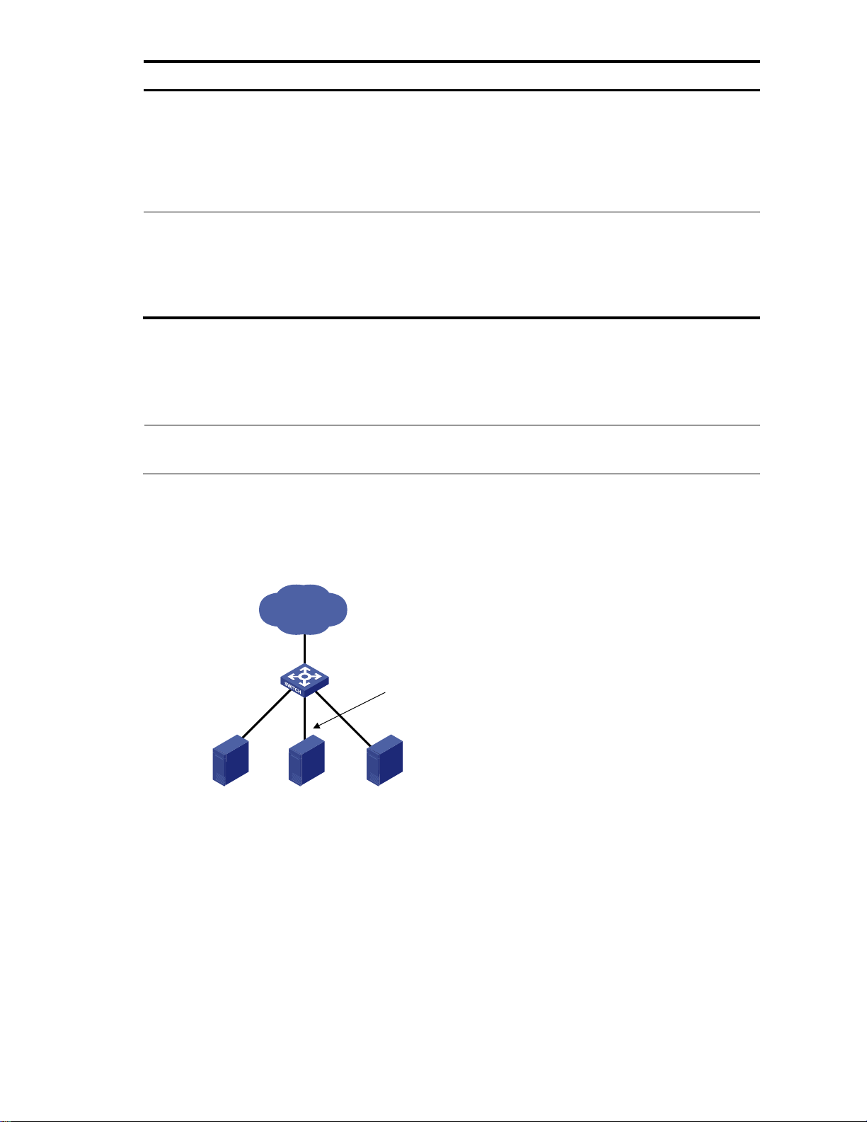
As shown in Figure 1, speed auto negotiation enables an Ethernet interface to negotiate with its peer for
the highest speed that both ends support by default. You can narrow down the speed option list for
negotiation.
Figure 1 Speed auto negotiation application scenario
All interfaces on the switch are operating in speed auto negotiation mode, with the highest speed of
1000 Mbps. If the transmission rate of each server in the server cluster is 1000 Mbps, their total
transmission rate will exceed the capability of interface GigabitEthernet 1/0/4, the interface providing
access to the Internet for the servers.
To avoid congestion on GigabitEthernet 1/0/4, set 100 Mbps as the only speed option available for
negotiation on interface GigabitEthernet 1/0/1, GigabitEthernet 1/0/2, and GigabitEthernet 1/0/3. As
a result, the transmission rate on each interface connected to a server is limited to 100 Mbps.
Follow these steps to configure an auto-negotiation transmission rate:
3
Page 11

To do…
Use the command…
Remarks
Enter system view
system-view
—
Enter Ethernet interface view
interface interface-type interfacenumber
—
Set speed options for auto
negotiation
speed auto [ 10 | 100 | 1000 ] *
Optional
NOTE:
This function is only available for Gigabit Layer-2 copper (electrical) Ethernet interfaces that support speed auto
negotiation.
The speed and speed auto commands supersede each other, and whichever is configured last takes effect.
Port A
Switch A Switch B
Port B
1000Mbps
Port C
100Mbps
1000Mbps
Port D
100Mbps
Switch C
To do…
Use the command…
Remarks
Enter system view
system-view
—
Enter Ethernet interface view
interface interface-type interfacenumber
—
Enable TxRx mode flow control
flow-control
Required
Use either command.
By default, flow control is
disabled on an Ethernet interface.
Enable Rx mode flow control
flow-control receive enable
Configuring generic flow control on an Ethernet interface
An interface implements generic flow control by sending and receiving common pause frames. The
following generic flow control modes are available:
TxRx mode enables an interface to both send and receive common pause frames.
Rx mode enables an interface to receive but not send common pause frames.
In Figure 2, when both Port A and Port B forward packets at 1000 Mbps, Port C is congested. To avoid
packet loss, enable flow control on Port A and Port B.
Figure 2 Flow control application scenario
Configure Port B to operate in TxRx mode, Port A in Rx mode.
When congestion occurs on Port C, Switch B buffers frames. When the amount of buffered frames
exceeds a certain value, Switch B sends a common pause frame out of Port B to ask Port A to
suspend sending packets. This pause frame also tells Port A for how long it is expected to pause.
Upon receiving the common pause frame from Port B, Port A suspends sending packets to Port B for
a period.
If congestion persists, Port B keeps sending common pause frames to Port A until the congestion
condition is removed.
Follow these steps to configure flow control on an interface:
4
Page 12

To do…
Use the command…
Remarks
Enter system view
system-view
—
Enter Ethernet interface view
interface interface-type
interface-number
—
Set a link-down suppression
interval
link-delay delay-time
Required
Link-down suppression is disabled by
default.
To do…
Use the command…
Remarks
Enter system view
system-view
—
Enter Ethernet interface view
interface interface-type interfacenumber
—
Set a link-up suppression interval
link-delay delay-time mode up
Required
Link-up suppression is disabled by
default.
Configuring link change suppression on an Ethernet interface
An Ethernet interface has two physical link states: up and down. Each time the physical link of an
interface goes up or comes down, the physical layer reports the change to the upper layers, and the
upper layers handle the change, resulting in increased overhead.
To prevent physical link flapping from affecting system performance, configure link change suppression to
delay the reporting of physical link state changes. When the delay expires, the interface reports any
detected change.
Link change suppression does not suppress administrative up or down events. When you shut down or
bring up an interface by using the shutdown or undo shutdown command, the interface reports the event
to the upper layers immediately.
On an A5120 EI switch, you can configure link-down suppression or link-up suppression, but not both.
Link-down suppression enables an interface to suppress link-down events and start a delay timer each time
the physical link goes down. During this delay, the interface does not report the link-down event, and the
display interface brief or display interface command displays the interface state as UP. If the physical link
is still down when the timer expires, the interface reports the link-down event to the upper layers.
Link-up suppression enables an interface to suppress link-up events and start a delay timer each time the
physical link goes up. During this delay, the interface does not report the link-up event, and the display
interface brief or display interface command displays the interface state as DOWN. If the physical link is
still up when the timer expires, the interface reports the link-up event to the upper layers.
Configuring link-down suppression
Follow these steps to enable an Ethernet interface to suppress link-down events:
Configuring link-up suppression
Follow these steps to configure link-up suppression on an Ethernet interface:
5
Page 13

NOTE:
The link-delay mode up command and the link-delay command supersedes each other, and whichever
is configured last takes effect.
Port 1 Port 2
Switching chip
Switch
Test packets
Looped packets
Port 1
Port 2
Switching chip
Switch
Loopback
plug
Test packets
Looped packets
To do…
Use the command…
Remarks
Enter system view
system-view
—
Enter Ethernet interface view
interface interface-type interfacenumber
—
Perform loopback testing
loopback { external | internal }
Required
Configuring loopback testing on an Ethernet interface
You can perform loopback testing on an Ethernet interface to determine whether the interface functions
properly. The Ethernet interface cannot forward data packets during the testing. Loopback testing falls into
the following categories:
Internal loopback testing, which tests all on-chip functions related to Ethernet interfaces. As shown in
Figure 3, internal loopback testing is performed on Port 1. During internal loopback testing, the
interface sends a certain number of test packets, which are looped back to the interface over the
self-loop created on the switching chip.
Figure 3 Internal loopback testing
External loopback testing, which tests the hardware of Ethernet interfaces. As shown in Figure 4,
external loopback testing is performed on Port 1. To perform external loopback testing on an
Ethernet interface, insert a loopback plug into the interface. During external loopback testing, the
interface sends a certain number of test packets, which are looped over the plug and back to the
interface. If the interface fails to receive any test packet, the hardware of the interface is faulty.
Figure 4 External loopback testing
Follow these steps to perform loopback testing on an Ethernet interface:
6
Page 14

NOTE:
On an interface that is physically down, you can only perform internal loopback testing. On an interface
administratively shut down, you can perform neither internal nor external loopback testing.
The speed, duplex, mdi, and shutdown commands are not available during loopback testing.
During loopback testing, the Ethernet interface operates in full duplex mode. When you disable loopback testing,
the port returns to its duplex setting.
To do…
Use the command…
Remarks
Enter system view
system-view
—
Create a port group and enter
port group view
port-group manual port-groupname
Required
Assign Ethernet interfaces to the
port group
group-member interface-list
Required
Shut down all Ethernet interfaces
in the port group
shutdown
Optional
By default, all Ethernet interfaces
in a port group are up. To bring
up all Ethernet interfaces shut
down manually in a port group,
use the undo shutdown command
in port group view.
Configuring a port group
Some interfaces on your switch might use the same set of settings. To configure these interfaces in bulk
rather than one by one, you can assign them to a port group.
You create port groups manually. All settings made for a port group apply to all the member ports of the
group. For example, you can configure a traffic suppression threshold (see ―Configuring traffic storm
protection‖) for multiple interfaces in bulk by assigning these interfaces to a port group.
Even though the settings are made on the port group, they are saved on each interface basis rather than
on a port group basis. You can only view the settings in the view of each interface by using the display
current-configuration or display this command.
Follow these steps to configure a port group:
Configuring traffic storm protection
A traffic storm occurs when a large amount of broadcast, multicast, or unknown unicast packets congest a
network. The A5120 EI switches provide the following storm protection approaches:
Storm suppression, which you can use to limit the size of monitored traffic that passes through an
Ethernet interface by setting a traffic threshold. The port discards all traffic that exceeds the
threshold.
Storm control, which you can use to shut down Ethernet interfaces or block traffic when monitored
traffic exceeds the traffic threshold. Depending on your configuration, storm control can also enable
an interface to send trap or log messages when monitored traffic reaches a certain traffic threshold.
For a particular type of traffic, configure either storm suppression or storm control, but not both. If you
configure both of them, you might fail to achieve the expected storm control effect.
7
Page 15

Configuring storm suppression on an Ethernet interface
NOTE:
If one suppression threshold has been set in pps on an Ethernet interface, you must set other
suppression thresholds in pps. If one suppression threshold has been set in percentage or kbps, you
cannot set other suppression thresholds in pps.
To do…
Use the command…
Remarks
Enter system view
system-view
—
Enter Ethernet
interface view
or port group
view
Enter Ethernet
interface view
interface interface-type interfacenumber
Use either command.
To configure storm suppression
on one Ethernet interface, enter
Ethernet interface view.
To configure storm suppression
on a group of Ethernet
interfaces, enter port group
view.
Enter port
group view
port-group manual port-group-name
Set a broadcast suppression
threshold
broadcast-suppression { ratio | pps
max-pps | kbps max-bps }
Optional
By default, all broadcast traffic
is allowed to pass through an
interface.
Set a multicast suppression
threshold
multicast-suppression { ratio | pps
max-pps | kbps max-bps }
Optional
By default, all multicast traffic is
allowed to pass through an
interface.
Set a unknown unicast
suppression threshold
unicast-suppression { ratio | pps maxpps | kbps max-bps }
Optional
By default, all unknown unicast
traffic is allowed to pass
through an interface.
NOTE:
If you set a storm suppression threshold in both Ethernet interface view and port group view, the
threshold configured last takes effect.
You can use the following guidelines to set one suppression threshold for broadcast, multicast, and
unknown unicast traffic separately on an Ethernet interface.
Set the threshold as a percentage of the interface transmission capability.
Set the threshold in kbps, limiting the number of kilobits of monitored traffic passing through the
interface per second.
Set the threshold in pps, limiting the number of monitored packets passing through the interface per
second.
Follow these steps to configure storm suppression on an Ethernet interface:
Configuring storm control on an Ethernet interface
Storm control compares broadcast, multicast, and unknown unicast traffic regularly with their respective
traffic thresholds on an Ethernet interface. For each type of traffic, storm control provides a lower threshold
and a higher threshold.
8
Page 16

For management purposes, you can configure the interface to send threshold event traps and log
To do…
Use the command…
Remarks
Enter system view
system-view
—
Set the traffic polling interval of
the storm control module
storm-constrain interval seconds
Optional
10 seconds by default.
Enter Ethernet interface view
interface interface-type interfacenumber
—
Enable storm control, and set the
lower and upper thresholds for
broadcast, multicast, or unknown
unicast traffic
storm-constrain { broadcast |
multicast | unicast } { pps | kbps |
ratio } max-pps-values min-pps-
values
Required
Disabled by default.
Set the control action to take
when monitored traffic exceeds
the upper threshold
storm-constrain control { block |
shutdown }
Optional
Disabled by default.
Enable the interface to send storm
control threshold event traps.
storm-constrain enable trap
Optional
By default, the interface sends
traps when monitored traffic
exceeds the upper threshold or
drops below the lower threshold
from the upper threshold.
Enable the interface to log storm
control threshold events.
storm-constrain enable log
Optional
By default, the interface outputs
log messages when monitored
traffic exceeds the upper
threshold or falls below the lower
threshold from the upper
threshold.
NOTE:
For network stability, use the default or set a higher traffic polling interval.
Storm control uses a complete polling cycle to collect traffic data, and analyzes the data in the next cycle. An
interface takes one to two polling intervals to take a storm control action.
messages when monitored traffic exceeds the upper threshold or falls below the lower threshold from the
upper threshold.
When the traffic exceeds its higher threshold, the interface does either of the following, depending on
your configuration:
Blocks the particular type of traffic, while forwarding other types of traffic. Even though the interface
does not forward the blocked traffic, it still counts the traffic. When the blocked traffic drops below
the threshold, the interface begins to forward the traffic.
Shuts down automatically. The interface shuts down automatically and stops forwarding any traffic.
To bring up the interface, use the undo shutdown command or disable the storm control function.
Follow these steps to configure the storm control function on an Ethernet interface:
Setting the statistics polling interval
Follow these steps to set the statistics polling interval on an Ethernet interface:
9
Page 17

To do…
Use the command…
Remarks
Enter system view
system-view
—
Enter Ethernet interface view
interface interface-type interfacenumber
—
Set the statistics polling interval on
the Ethernet interface
flow-interval interval
Optional
The default interface statistics
polling interval is 300 seconds.
To do…
Use the command…
Remarks
Enter system view
system-view
—
Enter Ethernet
interface view
or port group
view
Enter Ethernet
interface view
interface interface-type interfacenumber
Use either command.
To configure auto power-down on
one Ethernet interface, enter
Ethernet interface view.
To configure auto power-down on
a group of Ethernet interfaces,
enter port group view.
Enter port
group view
port-group manual port-group-name
Enable auto power-down on an
Ethernet interface
port auto-power-down
Required
Disabled by default.
To do…
Use the command…
Remarks
Enter system view
system-view
—
Enter Ethernet
interface view
Enter Ethernet
interface view
interface interface-type
interface-number
Use either command.
To display the interface statistics collected in the last polling interval, use the display interface command.
To clear interface statistics, use the reset counters interface command.
Enabling the auto power-down function on an Ethernet interface
To save power, enable the auto power-down function on Ethernet interfaces. An interface enters the power
save mode if it has not received any packet for a certain period of time (this interval depends on the
specifications of the chip, and is not configurable). When a packet arrives later, the interface enters its
normal state.
Follow these steps to enable auto power-down on an Ethernet interface:
Configuring jumbo frame support
Ethernet frames longer than the standard Ethernet frame size (1536 bytes) are called "jumbo frames",
which are typical of file transfer.
If you set an Ethernet interface to accept jumbo frames, it allows frames up to 9216 bytes to pass
through.
If you disable an Ethernet interface to accept jumbo frames, it allows frames up to 1536 bytes to
pass through.
Follow these steps to configure jumbo frame support in Ethernet interface view:
10
Page 18

To do…
Use the command…
Remarks
or port group
view
Enter port
group view
To configure jumbo frame support on one
Ethernet interface, enter Ethernet interface
view.
To configure jumbo frame support on a
group of Ethernet interfaces, enter port
group view.
Enable the interface to accept
jumbo frames
jumboframe enable
Required
By default, an Ethernet interface accepts
jumbo frames (up to 9216 bytes).
Port type
Actions
No protective action is configured
A protective action is configured
Access interface
Put the interface in controlled mode.
The interface discards all incoming
packets, but still forwards outgoing
traffic.
Create traps.
Delete all MAC address entries of
the interface.
Perform the configured protective
action.
Create traps and log messages.
Delete all MAC address entries of the
interface.
Hybrid or trunk
interface
Create traps.
If loopback detection control is
enabled, set the interface in
controlled mode. The interface
discards all incoming packets, but
still forwards outgoing packets.
Delete all MAC address entries of
the interface.
Create traps and log messages.
If loopback detection control is
enabled, take the configured
protective action on the interface.
Delete all MAC address entries of the
interface.
To do…
Use the command…
Remarks
Enter system view
system-view
—
Enable global loopback detection
loopback-detection enable
Required
Disabled by default.
Set the loopback detection
interval
loopback-detection interval-time
time
Optional
30 seconds by default.
Enabling single-port loopback detection on an Ethernet interface
If an interface receives a packet that it sent, a loop occurs. Loops might cause broadcast storms,
degrading network performance. You can use loopback detection to detect loops on an interface and
configure the protective action to take on the interface when a loop is detected, for example, to shut
down the interface. In addition to the configured protective action, the switch also performs other actions
to alleviate the impact of the loop condition, as described in Table 1.
Table 1 Actions to take upon detection of a loop condition
Follow these steps to configure single-port loopback detection:
11
Page 19

To do…
Use the command…
Remarks
Enter
Ethernet
interface
view or port
group view
Enter Ethernet
interface view
interface interface-type interface-
number
Use either command.
To configure loopback detection
on one interface, enter Ethernet
interface view.
To configure loopback detection
on a group of Ethernet interfaces,
enter port group view.
Enter port group
view
port-group manual port-group-
name
Enable loopback detection on the
interface
loopback-detection enable
Required
Disabled by default.
Enable loopback detection control
loopback-detection control enable
Optional
Disabled by default.
Enable loopback detection in all
VLANs on the trunk or hybrid
interface
loopback-detection per-vlan
enable
Optional
By default, a trunk or hybrid
interface performs loopback
detection only in its PVID.
Set the protective action to take
on the interface when a loop is
detected
loopback-detection action {
shutdown | semi-block | nolearning }
Optional
By default, a looped interface
discards all incoming packets but
still forwards outgoing packets.
The system generates traps and
deletes all MAC address entries
of the looped interface.
With the shutdown keyword used,
the switch shuts down looped
Ethernet interfaces and sets their
physical state to Loop down.
When a looped interface
recovers, you must use the undo
shutdown command to restore its
forwarding capability.
NOTE:
To use single-port loopback detection on an Ethernet interface, you must enable the function both globally and
on the interface.
To disable loopback detection on all interfaces, run the undo loopback-detection enable command in system
view.
To enable a hybrid or trunk interface to take the administratively specified protective action, you must use the
loopback-detection control enable command on the interface.
When you change the link type of an Ethernet interface by using the port link-type command, the switch
removes the protective action configured on the interface. For more information about the port link-type
command, see the
Layer 2—LAN Switching Command Reference
.
Enabling multi-port loopback detection
When an interface receives packets sent from another interface on the same switch, a loop occurs
between the two interfaces. Such a loop is called a "multi-port loop". As shown in Figure 5, if Port 1
receives packets sent out Port 2, a multi-port loop occurs between the two interfaces, and Port 1 (the
12
Page 20

interface that receives the looped packets) is the looped interface. Multi-port loops might also cause
LAN
Port 1 Port 2
Switch A
Loop
To do…
Use the command…
Remarks
Enter system view
system-view
—
Enable multi-port loopback
detection
loopback-detection multi-portmode enable
Required
Disabled by default.
NOTE:
To enable multi-port loopback detection, you must configure the loopback-detection multi-port-mode enable
and loopback-detection enable commands in system view, and configure the loopback-detection enable
command in the view of the related interfaces.
The single-port loopback detection function is available when the switch is performing multi-port loopback
detection.
NOTE:
Optical interfaces do not support the MDI mode setting.
broadcast storms.
Figure 5 Network diagram for multi-port loopback detection
The multi-port loopback detection function detects loops among interfaces on your switch. You can use the
loopback-detection action command to configure the protective action to take on looped interfaces— for
example, to shut down the interface, eliminating the loops. In addition, the switch also takes other link
type-dependant actions on the looped interface (for example, Port 1 in Figure 5) to alleviate the impact of
the loop condition. For more information, see ―Setting the statistics polling interval.‖
Multi-port loopback detection is implemented on the basis of single-port loopback detection
configurations on Ethernet interfaces. To implement multi-port loopback detection, you must enable singleport loopback detection on one or multiple Ethernet interfaces on the switch.
Follow these steps to configure multi-port loopback detection:
Setting the MDI mode of an Ethernet interface
You can use both crossover and straight-through Ethernet cables to connect copper Ethernet interfaces. To
accommodate these types of cables, a copper Ethernet interface can operate in one of the following
Medium Dependent Interface (MDI) modes:
Across mode
Normal mode
Auto mode
13
Page 21

A copper Ethernet interface uses an RJ-45 connector, which comprises eight pins, each of which plays a
To do…
Use the command…
Remarks
Enter system view
system-view
—
Enter Ethernet interface view
interface interface-type interfacenumber
—
Set the MDI mode of the Ethernet
interface
mdi { across | auto | normal }
Optional
By default, a copper Ethernet
interface operates in auto mode to
negotiate pin roles with its peer.
To do…
Use the command…
Remarks
Enter system view
system-view
—
Enter Ethernet interface view
interface interface-type interfacenumber
—
Enable bridging on the Ethernet
interface
port bridge enable
Required
Disabled by default.
dedicated role. For example, pins 1 and 2 transmit signals, and pins 3 and 6 receive signals. The pin
role varies by the MDI modes as follows:
In normal mode, pins 1 and 2 are transmit pins, and pins 3 and 6 are receive pins.
In across mode, pins 1 and 2 are receive pins, and pins 3 and 6 are transmit pins.
In auto mode, the interface negotiates pin roles with its peer.
To enable the interface to communicate with its peer, ensure that its transmit pins are connected to the
remote receive pins. If the interface can detect the connection cable type, set the interface in auto MDI
mode. If not, set its MDI mode by using the following guidelines:
When a straight-through cable is used, set the interface to work in the MDI mode different than its
peer.
When a crossover cable is used, set the interface to work in the same MDI mode as its peer, or set
either end to work in auto mode.
Follow these steps to set the MDI mode of an Ethernet interface:
Enabling bridging on an Ethernet interface
When an incoming packet arrives, the switch looks up the destination MAC address of the packet in the
MAC address table. If an entry is found, but the outgoing interface is the same as the receiving interface
(for example, if the destination and source MAC addresses of the packet are the same), the switch
discards the packet.
To enable the switch to return such packets to the sender through the receiving interface rather than drop
them, enable the bridging function on the Ethernet interface.
Follow these steps to enable bridging on an Ethernet interface:
Testing the cable connection of an Ethernet interface
14
Page 22

NOTE:
Optical interfaces do not support this feature.
If the link of an Ethernet interface is up, testing its cable connection will cause the link to come down and then go
up.
To do…
Use the command…
Remarks
Enter system view
system-view
—
Enter Ethernet interface view
interface interface-type interfacenumber
—
Test the cable connected to the
Ethernet interface
virtual-cable-test
Required
To do…
Use the command…
Remarks
Display the current state of an
interface and the related
information
display interface [ interface-type [ interface-
number ] ] [ | { begin | exclude | include }
regular-expression ]
Available in any view
Display the summary of an
interface
display interface [ interface-type [ interface-
number ] ] brief [ | { begin | exclude |
include } regular-expression ]
display interface [ interface-type ] brief
down [ | { begin | exclude | include }
regular-expression ]
Available in any view
Display the statistics on the
packets that pass through a
specific type of interfaces
display counters { inbound | outbound }
interface [ interface-type ] [ | { begin |
exclude | include } regular-expression ]
Available in any view
Display the statistics on the rate of
the packets that pass through the
interfaces that are of a specific
type and are in the up state in the
latest sampling interval
display counters rate { inbound | outbound }
interface [ interface-type ] [ | { begin |
exclude | include } regular-expression ]
Available in any view
Display information about
discarded packets on an interface
display packet-drop interface [ interface-type
[ interface-number ] ] [ | { begin | exclude |
include } regular-expression ]
Available in any view
Display summary information
about discarded packets on all
interfaces
display packet-drop summary [ | { begin |
exclude | include } regular-expression ]
Available in any view
Display information about a
manual port group or all manual
port groups
display port-group manual [ all | name port-
group-name ] [ | { begin | exclude | include
} regular-expression ]
Available in any view
You can test the cable connection of an Ethernet interface for a short or open circuit. The device displays
cable test results within five seconds. If any fault is detected, the test results include the length of the faulty
cable segment.
Follow these steps to test the cable connection of an Ethernet interface:
Displaying and maintaining an Ethernet interface
15
Page 23

To do…
Use the command…
Remarks
Display information about the
loopback function
display loopback-detection [ | { begin |
exclude | include } regular-expression ]
Available in any view
Display information about storm
control on interfaces
display storm-constrain [ broadcast |
multicast | unicast ] [ interface interface-type
interface-number ] [ | { begin | exclude |
include } regular-expression ]
Available in any view
Clear the statistics of an interface
reset counters interface [ interface-type [
interface-number ] ]
Available in user view
Clear the statistics of discarded
packets on an interface
reset packet-drop interface [ interface-type [
interface-number ] ]
Available in user view
Display the combo interfaces and
the fiber and copper combo ports
display port combo [ | { begin | exclude |
include } regular-expression ]
Available in any view
16
Page 24

To do…
Use the command…
Remarks
Enter system view
system-view
—
Create a loopback interface and
enter loopback interface view
interface loopback interface-
number
—
Set a description for the loopback
interface
description text
Optional
By default, the description of an
interface is the interface name
followed by the ―Interface‖ string.
Shut down the loopback interface
shutdown
Optional
By default, a loopback interface is
up after it is created.
Loopback and null interface configuration
Loopback interface
Introduction to loopback interface
A loopback interface is a software-only virtual interface. It delivers the following benefits.
The physical layer state and link-layer protocols of a loopback interface are always up unless the
loopback interface is manually shut down.
To save IP address resources, you can assign an IP address with an all-F mask to a loopback
interface. When you assign an IPv4 address whose mask is not 32-bit, the system automatically
changes the mask into a 32-bit mask. When you assign an IPv6 address whose mask is not 128-bit,
the system automatically changes the mask into a 128-bit mask.
You can enable routing protocols on a loopback interface, and a loopback interface can send and
receive routing protocol packets.
You can configure a loopback interface address as the source address of the IP packets that the switch
generates. Because loopback interface addresses are stable unicast addresses, they are usually used as
device identifications. When you configure a rule on an authentication or security server to permit or
deny packets that a switch generates, you can simplify the rule by configuring it to permit or deny packets
that carry the loopback interface address that identifies the switch. When you use a loopback interface
address as the source address of IP packets, be sure to perform any necessary routing configuration to
ensure that the route from the loopback interface to the peer is reachable. All data packets sent to the
loopback interface are treated as packets sent to the switch itself, so the switch does not forward these
packets.
Configuring a loopback interface
Follow these steps to configure a loopback interface:
17
Page 25

NOTE:
You can configure settings such as IP addresses and IP routes on loopback interfaces. For more
information, see the
Layer 3—IP Services Configuration Guide
and
Layer 3—IP Routing Configuration
Guide
.
To do…
Use the command…
Remarks
Enter system view
system-view
—
Enter null interface view
interface null 0
Required
The Null 0 interface is the default null interface
on your switch. It cannot be manually created
or removed.
Set a description for the
null interface
description text
Optional
By default, the description of an interface is
the interface name followed by the ―Interface‖
string.
To do…
Use the command…
Remarks
Display information
about loopback
interfaces
display interface loopback [ brief [ down ] ] [ | {
begin | exclude | include } regular-expression ]
display interface loopback interface-number [ brief ] [
| { begin | exclude | include } regular-expression ]
Available in any view
Null interface
Introduction to null interface
A null interface is a completely software-based logical interface, and is always up. However, you cannot
use it to forward data packets or configure an IP address or link-layer protocol on it. With a null interface
specified as the next hop of a static route to a specific network segment, any packets routed to the
network segment are dropped. The null interface provides a simpler way to filter packets than ACL. You
can filter uninteresting traffic by transmitting it to a null interface instead of applying an ACL.
For example, by executing the ip route-static 92.101.0.0 255.255.0.0 null 0 command (which configures a
static route that leads to null interface 0), you can have all the packets destined to the network segment
92.101.0.0/16 discarded.
Only one null interface, Null 0, is supported on your switch. You cannot remove or create a null interface.
Configuring null 0 interface
Follow these steps to enter null interface view:
Displaying and maintaining loopback and null interfaces
18
Page 26

To do…
Use the command…
Remarks
Display information
about the null interface
display interface null [ brief [ down ] ] [ | { begin |
exclude | include } regular-expression ]
display interface null 0 [ brief ] [ | { begin | exclude
| include } regular-expression ]
Available in any view
Clear the statistics on a
loopback interface
reset counters interface [ loopback [ interface-number
] ]
Available in user view
Clear the statistics on the
null interface
reset counters interface [ null [ 0 ] ]
Available in user view
19
Page 27

MAC address table configuration
Overview
Every Ethernet switch maintains a MAC address table for forwarding frames through unicast instead of
broadcast. This table describes from which port a MAC address (or host) can be reached. When
forwarding a frame, the switch first looks up the MAC address of the frame in the MAC address table for
a match. If the switch finds an entry, it forwards the frame out of the outgoing port in the entry. If the
switch does not find an entry, it broadcasts the frame out of all but the incoming port.
How a MAC address table entry is created
The switch automatically obtains entries in the MAC address table, or you can add them manually.
MAC address learning
The switch can automatically populate its MAC address table by obtaining the source MAC addresses
(called ―MAC address learning‖) of incoming frames on each port.
When a frame arrives at a port, Port A for example, the switch performs the following tasks:
1. Verifies the source MAC address (for example, MAC-SOURCE) of the frame.
2. Looks up the MAC address in the MAC address table.
3. Updates an entry if it finds one. If the switch does not find an entry, it adds an entry for MAC-
SOURCE and Port A.
The switch performs the learning process each time it receives a frame from an unknown source MAC
address, until the MAC address table is fully populated.
After obtaining the source MAC address of a frame, the switch looks up the destination MAC address in
the MAC address table. If the switch finds an entry for the MAC address, it forwards the frame out of the
specific outgoing port, Port A in this example.
Manually configuring MAC address entries
With dynamic MAC address learning, a switch does not distinguish between illegitimate and legitimate
frames, which can invite security hazards. For example, if a hacker sends frames with a forged source
MAC address to a port different from the one that the real MAC address is connected to, the switch will
create an entry for the forged MAC address, and forward frames destined for the legal user to the hacker
instead.
To enhance the security of a port, you can bind specific user devices to the port by manually adding
MAC address entries into the MAC address table of the switch. Because manually configured entries have
higher priority than dynamically obtained ones, you can prevent hackers from stealing data using forged
MAC addresses.
Types of MAC address table entries
A MAC address table can contain the following types of entries:
Static entries, which are manually added and never age out.
20
Page 28

NOTE:
A static or blackhole MAC address entry can overwrite a dynamic MAC address entry, but not vice
versa.
NOTE:
The MAC address table can contain only Layer 2 Ethernet ports and Layer 2 aggregate interfaces.
This document covers configuring static, dynamic, and blackhole unicast MAC address table entries. For more
information about static multicast MAC address table entries, see the
IP Multicast Configuration Guide
.
Dynamic entries, which can be manually added or dynamically obtained and might age out.
Blackhole entries, which are manually configured and never age out. Blackhole entries are
configured for filtering out frames with specific destination MAC addresses. For example, to block all
packets destined for a specific user for security concerns, you can configure the MAC address of this
user as a blackhole destination MAC address entry.
To adapt to network changes and prevent inactive entries from occupying table space, an aging
mechanism is adopted for dynamic MAC address entries. Each time a dynamic MAC address entry
obtained or created, an aging time starts. If the entry has not updated when the aging timer expires, the
switch deletes the entry. If the entry has updated before the aging timer expires, the aging timer restarts.
MAC address table-based frame forwarding
When forwarding a frame, the switch adopts the following forwarding modes based on the MAC
address table:
Unicast mode: If an entry is available for the destination MAC address, the switch forwards the
frame out of the outgoing interface indicated by the MAC address table entry.
Broadcast mode: If the switch receives a frame with the destination address as all ones, or no entry
is available for the destination MAC address, the switch broadcasts the frame to all the interfaces
except the receiving interface.
Configuring the MAC address table
The MAC address table configuration tasks include:
Manually configuring MAC address table entries
Disabling MAC address learning
Configuring the aging timer for dynamic MAC address entries
Configuring the MAC learning limit on ports
These configuration tasks are all optional and can be performed in any order.
Manually configuring MAC address table entries
To help prevent MAC address spoofing attacks and improve port security, you can manually add MAC
address table entries to bind ports with MAC addresses. You can also configure blackhole MAC address
entries to filter out packets with certain source or destination MAC addresses.
Follow these steps to add, modify, or remove entries in the MAC address table in system view:
21
Page 29

To do…
Use the command…
Remarks
Enter system view
system-view
—
Configure MAC
address table
entries
Configure static or
dynamic MAC
address table
entries
mac-address { dynamic | static } macaddress interface interface-type
interface-number vlan vlan-id
Required
Use either command.
Make sure that you
have created the VLAN
and assign the
interface to the VLAN.
Configure
blackhole MAC
address table
entries
mac-address blackhole mac-address
vlan vlan-id
To do…
Use the command…
Remarks
Enter system view
system-view
—
Enter interface view
interface interface-type interfacenumber
—
Configure a MAC address table
entry
mac-address { dynamic | static }
mac-address vlan vlan-id
Required
Ensure that you have created the
VLAN and assign the interface to
the VLAN
To do…
Use the command…
Remarks
Enter system view
system-view
—
Disable global MAC address
learning
mac-address mac-learning
disable
Required
Enabled by default.
NOTE:
When MAC address learning is disabled, the obtained MAC addresses remain valid until they age out.
Follow these steps to add or modify a MAC address table entry in interface view:
Disabling MAC address learning
Sometimes, you might need to disable MAC address learning to prevent the MAC address table from
being saturated, for example, when your switch is being attacked by a large amount of packets with
different source MAC addresses.
Disabling global MAC address learning
Disabling global MAC address learning disables the learning function on all ports.
Follow these steps to disable MAC address learning:
Disabling MAC address learning on ports
After enabling global MAC address learning, you can disable the function on a single port, or on all
ports in a port group as needed.
Follow these steps to disable MAC address learning on an interface or a port group:
22
Page 30

To do…
Use the command…
Remarks
Enter system view
system-view
—
Enable global MAC address
learning
undo mac-address mac-learning
disable
Optional
Enabled by default.
Enter
interface view
or port group
view
Enter Layer 2
Ethernet interface
view or Layer 2
aggregate interface
view
interface interface-type interfacenumber
Required
Use either command.
The configuration made in Layer
2 Ethernet or Layer 2 aggregate
interface view takes effect on the
current interface only. The
configuration made in port
group view takes effect on all
the member ports in the port
group.
Enter port group
view
port-group manual port-group-
name
Disable MAC address learning on
the interface or all ports in the port
group
mac-address mac-learning
disable
Required
Enabled by default.
NOTE:
When MAC address learning is disabled, the obtained MAC addresses remain valid until they age out.
For more information about port groups, see the chapter ―Ethernet interface configuration.‖
To do…
Use the command…
Remarks
Enter system view
system-view
—
Configure the aging timer for
dynamic MAC address entries
mac-address timer { aging
seconds | no-aging }
Optional
300 seconds by default.
Configuring the aging timer for dynamic MAC address entries
The MAC address table uses an aging timer for dynamic MAC address entries for security and efficient
use of table space. If a dynamic MAC address entry has failed to update before the aging timer expires,
the switch deletes the entry. This aging mechanism ensures that the MAC address table can quickly
update to accommodate the latest network changes.
Set the aging timer appropriately. A long aging interval might cause the MAC address table to retain
outdated entries, exhaust the MAC address table resources, and fail to update its entries to accommodate
the latest network changes. A short interval might result in the removal of valid entries and unnecessary
broadcasts, which might affect device performance.
Follow these steps to configure the aging timer for dynamic MAC address entries:
You can reduce broadcasts on a stable network by disabling the aging timer to prevent dynamic entries
from unnecessarily aging out. By reducing broadcasts, you improve not only network performance, but
also security, because you reduce the chances that a data packet will reach unintended destinations.
23
Page 31

To do…
Use the command…
Remarks
Enter system view
system-view
—
Enter Layer 2
Ethernet
interface view
or port group
view
Enter Layer 2 Ethernet
interface view
interface interface-type
interface-number
Use either command.
The configuration made in Layer
2 Ethernet interface view takes
effect on the current interface
only. The configuration made in
port group view takes effect on
all the member ports in the port
group.
Enter port group view
port-group manual port-
group-name
Configure the MAC learning limit on the
interface or port group
mac-address max-maccount count
Required
No MAC learning limit is
configured by default.
NOTE:
Layer 2 aggregate interfaces do not support the mac-address max-mac-count command.
Do not configure the MAC learning limit on any member ports of an aggregation group. Otherwise, the
member ports cannot be selected.
To do…
Use the command…
Remarks
Display MAC address table
information
display mac-address [ mac-address [ vlan vlan-id ]
| [ [ dynamic | static ] [ interface interface-type
interface-number ] | blackhole ] [ vlan vlan-id ] [
count ] ] [ | { begin | exclude | include } regular-
expression ]
Available in any
view
Display the aging timer for
dynamic MAC address
entries
display mac-address aging-time [ | { begin |
exclude | include } regular-expression ]
Available in any
view
Display the system or
interface MAC address
learning state
display mac-address mac-learning [ interface-type
interface-number ] [ | { begin | exclude | include }
regular-expression ]
Available in any
view
Display MAC address
statistics
display mac-address statistics [ | { begin | exclude
| include } regular-expression ]
Available in any
view
Configuring the MAC learning limit on ports
As the MAC address table is growing, the forwarding performance of your device might degrade. To
prevent the MAC address table from getting so large that the forwarding performance degrades, you can
limit the number of MAC addresses that a port can obtain.
Follow these steps to configure the MAC learning limit on a Layer 2 Ethernet interface or all ports in a
port group:
Displaying and maintaining MAC address tables
24
Page 32

MAC address table configuration example
Network requirements
The MAC address of one host is 000f-e235-dc71 and belongs to VLAN 1. It is connected to
GigabitEthernet 1/0/1 of the device. To prevent MAC address spoofing, add a static entry into the
MAC address table of the device for the host.
The MAC address of another host is 000f-e235-abcd and belongs to VLAN 1. Because this host
once behaved suspiciously on the network, you can add a destination blackhole MAC address entry
for the MAC address to drop all packets destined for the host.
Set the aging timer for dynamic MAC address entries to 500 seconds.
Configuration procedure
# Add a static MAC address entry.
<Sysname> system-view
[Sysname] mac-address static 000f-e235-dc71 interface gigabitethernet 1/0/1 vlan 1
# Add a destination blackhole MAC address entry.
[Sysname] mac-address blackhole 000f-e235-abcd vlan 1
# Set the aging timer for dynamic MAC address entries to 500 seconds.
[Sysname] mac-address timer aging 500
# Display the MAC address entry for port GigabitEthernet 1/0/1.
[Sysname] display mac-address interface gigabitethernet 1/0/1
MAC ADDR VLAN ID STATE PORT INDEX AGING TIME
000f-e235-dc71 1 Config static GigabitEthernet 1/0/1 NOAGED
--- 1 mac address(es) found ---
# Display information about the destination blackhole MAC address table.
[Sysname] display mac-address blackhole
MAC ADDR VLAN ID STATE PORT INDEX AGING TIME
000f-e235-abcd 1 Blackhole N/A NOAGED
--- 1 mac address(es) found ---
# View the aging time of dynamic MAC address entries.
[Sysname] display mac-address aging-time
Mac address aging time: 500s
25
Page 33

To do…
Use the command…
Remarks
Enter system view
system-view
—
Enable MAC Information globally
mac-address information enable
Required
Disabled by default.
MAC Information configuration
Overview
Introduction to MAC Information
To monitor a network, you must monitor users who are joining and leaving the network. Because a MAC
address uniquely identifies a network user, you can monitor users who are joining and leaving a network
by monitoring their MAC addresses.
With the MAC Information function, Layer 2 Ethernet interfaces send Syslog or trap messages to the
monitor end in the network when they obtain or delete MAC addresses. By analyzing these messages,
the monitor end can monitor users who are accessing the network.
How MAC Information works
When a new MAC address is obtained or an existing MAC address is deleted on a device, the device
writes related information about the MAC address to the buffer area used to store user information. When
the timer set for sending MAC address monitoring Syslog or trap messages expires, or when the buffer
reaches capacity, the device sends the Syslog or trap messages to the monitor end.
Configuring MAC Information
The MAC Information configuration tasks include:
Enabling MAC Information globally
Enabling MAC Information on an interface
Configuring MAC Information mode
Configuring the interval for sending Syslog or trap messages
Configuring the MAC Information queue length
Enabling MAC Information globally
Follow these steps to enable MAC Information globally:
Enabling MAC Information on an interface
Follow these steps to enable MAC Information on an interface:
26
Page 34

To do…
Use the command…
Remarks
Enter system view
system-view
—
Enter Layer 2 Ethernet interface
view
interface interface-type interfacenumber
—
Enable MAC Information on the
interface
mac-address information enable {
added | deleted }
Required
Disabled by default.
NOTE:
To enable MAC Information on an Ethernet interface, enable MAC Information globally first.
To do…
Use the command…
Remarks
Enter system view
system-view
—
Configure MAC Information mode
mac-address information mode {
syslog | trap }
Optional
trap by default.
To do…
Use the command…
Remarks
Enter system view
system-view
—
Set the interval for sending Syslog
or trap messages
mac-address information interval
interval-time
Optional
One second by default.
To do…
Use the command…
Remarks
Enter system view
system-view
—
Configure the MAC Information
queue length
mac-address information queuelength value
Optional
50 by default.
Configuring MAC Information mode
Follow these steps to configure MAC Information mode:
Configuring the interval for sending Syslog or trap messages
To prevent Syslog or trap messages from being sent too frequently, you can set the interval for sending
Syslog or trap messages.
Follow these steps to set the interval for sending Syslog or trap messages:
Configuring the MAC Information queue length
To avoid losing user MAC address information, when the buffer that stores user MAC address information
reaches capacity, the user MAC address information in the buffer is sent to the monitor end in the
network, even if the timer set for sending MAC address monitoring Syslog or trap messages has not
expired yet.
Follow these steps to configure the MAC Information queue length:
27
Page 35

Host A
192.168.1.1/24
Host B
192.168.1.2/24
Server
192.168.1.3/24
Device
GE1/0/1 GE1/0/2
GE1/0/3
MAC Information configuration example
Network requirements
Host A is connected to a remote server (Server) through Device.
Enable MAC Information on GigabitEthernet 1/0/1 on Device. Device sends MAC address changes
in Syslog messages to Host B through GigabitEthernet 1/0/3. Host B analyzes and displays the
Syslog messages.
Figure 6 Network diagram for MAC Information configuration
Configuration procedure
1. Configure Device to send Syslog messages to Host B.
For more information, see the Network Management and Monitoring Configuration Guide.
2. Enable MAC Information.
# Enable MAC Information on Device.
<Device> system-view
[Device] mac-address information enable
# Configure MAC Information mode as Syslog.
[Device] mac-address information mode syslog
# Enable MAC Information on GigabitEthernet 1/0/1.
[Device] interface gigabitethernet 1/0/1
[Device-GigabitEthernet1/0/1] mac-address information enable added
[Device-GigabitEthernet1/0/1] mac-address information enable deleted
[Device-GigabitEthernet1/0/1] quit
# Set the MAC Information queue length to 100.
[Device] mac-address information queue-length 100
# Set the interval for sending Syslog or trap messages to 20 seconds.
[Device] mac-address information interval 20
28
Page 36

GE1/0/2
GE1/0/1
GE1/0/3
Link aggregation 1
GE1/0/2
GE1/0/1
GE1/0/3
Device A Device B
NOTE:
The rate of an aggregate interface equals the total rate of its member ports in the Selected state, and its
duplex mode is the same as the selected member ports. For more information about the states of
member ports in an aggregation group, see ―Aggregation states of member ports in an aggregation
group.‖
Ethernet link aggregation configuration
Overview
Ethernet link aggregation, or simply link aggregation, combines multiple physical Ethernet ports into one
logical link, called an ―aggregate link‖. Link aggregation delivers the following benefits:
Increases bandwidth beyond the limits of any single link. In an aggregate link, traffic is distributed
across the member ports.
Improves link reliability. The member ports dynamically back up one another. When a member port
fails, its traffic is automatically switched to other member ports.
As shown in Figure 7, Device A and Device B are connected by three physical Ethernet links. These
physical Ethernet links are combined into an aggregate link, Link aggregation 1. The bandwidth of this
aggregate link is as high as the total bandwidth of the three physical Ethernet links. At the same time, the
three Ethernet links back up each other.
Figure 7 Diagram for Ethernet link aggregation
Basic concepts
Aggregation group, member port, aggregate interface
Link aggregation is implemented through link aggregation groups. An aggregation group is a group of
Ethernet interfaces aggregated together, which are called ―member ports‖ of the aggregation group. For
each aggregation group, a logical interface, called an ―aggregate interface‖, is created. To an upper
layer entity that uses the link aggregation service, a link aggregation group appears to be a single
logical link and data traffic is transmitted through the aggregate interface.
When you create an aggregate interface, the switch automatically creates an aggregation group of the
same type and number as the aggregate interface. For example, when you create interface Bridgeaggregation 1, Layer 2 aggregation group 1 is created.
You can assign Layer 2 Ethernet interfaces only to a Layer 2 aggregation group.
Aggregation states of member ports in an aggregation group
A member port in an aggregation group can be in either of the following aggregation states:
Selected: A Selected port can forward user traffic.
29
Page 37

Feature
Considerations
Port isolation
Whether the port has joined an isolation group
QinQ
QinQ enable state (enable/disable), TPID for VLAN tags, outer VLAN tags to
be added, inner-to-outer VLAN priority mappings, inner-to-outer VLAN tag
mappings, inner VLAN ID substitution mappings
VLAN
Permitted VLAN IDs, PVID, link type (trunk, hybrid, or access), IP subnet-based
VLAN configuration, protocol-based VLAN configuration, VLAN tagging mode
MAC address learning
MAC address learning capability, MAC address learning limit, forwarding of
frames with unknown destination MAC addresses after the MAC address
learning limit is reached
NOTE:
Class-two configurations made on an aggregate interface are automatically synchronized to all member ports of
the interface. These configurations are retained on the member ports even after the aggregate interface is
removed.
Any class-two configuration change might affect the aggregation state of link aggregation member ports and
ongoing traffic. To be sure that you are aware of the risk, the system displays a warning message every time you
attempt to change a class-two configuration setting on a member port.
Unselected: An Unselected port cannot forward user traffic.
Operational key
When aggregating ports, the system automatically assigns each port an operational key based on port
information such as port rate and duplex mode. Any change to this information triggers a recalculation of
this operational key.
In an aggregation group, all selected member ports are assigned the same operational key.
Configuration classes
Every configuration setting on a port might affect its aggregation state. Port configurations fall into the
following classes:
Port attribute configurations, including port rate, duplex mode, and link status (up/down). These are
the most basic port configurations.
Class-two configurations. A member port can be placed in the Selected state only if it has the same
class-two configurations as the aggregate interface.
Table 2 Class-two configurations
Class-one configurations do not affect the aggregation state of the member port even if they are
different from those on the aggregate interface. GVRP and MSTP settings are examples of class-one
configurations.
Reference port
When setting the aggregation state of the ports in an aggregation group, the system automatically picks
a member port as the reference port. A Selected port must have the same port attributes and class-two
configurations as the reference port.
30
Page 38

Category
Description
Basic LACP functions
Implemented through the basic LACPDU fields, including the system LACP priority,
system MAC address, port LACP priority, port number, and operational key.
Each member port in a LACP-enabled aggregation group exchanges the
preceding information with its peer. When a member port receives an LACPDU, it
compares the received information with the information received on the other
member ports. In this way, the two systems reach an agreement on which ports
should be placed in the Selected state.
Extended LACP
functions
Implemented by extending the LACPDU with new Type/Length/Value (TLV) fields.
This is how the LACP multi-active detection (MAD) mechanism of the Intelligent
Resilient Framework (IRF) feature is implemented. An A5120 EI Switch Series can
participate in LACP MAD as either an IRF member switch or an intermediate
device.
NOTE:
For more information about IRF, member switches, intermediate devices, and the LACP MAD
mechanism, see the
IRF Configuration Guide
.
Type
Description
Remarks
System LACP
priority
Used by two peer devices (or systems) to determine which one is
superior in link aggregation.
In dynamic link aggregation, the system that has higher system LACP
priority sets the Selected state of member ports on its side first, and
then the system that has lower priority sets the port state accordingly.
The smaller the
priority value,
the higher the
priority.
Port LACP priority
Determines the likelihood of a member port to be selected on a
system. The higher the port LACP priority, the higher the likelihood.
LACP
The IEEE 802.3ad Link Aggregation Control Protocol (LACP) enables dynamic aggregation of physical
links. It uses link aggregation control protocol data units (LACPDUs) for exchanging aggregation
information between LACP-enabled devices.
1. LACP functions
The IEEE 802.3ad LACP offers basic LACP functions and extended LACP functions, as described in Table
3.
Table 3 Basic and extended LACP functions
2. LACP priorities
LACP priorities have two types: system LACP priority and port LACP priority.
Table 4 LACP priorities
3. LACP timeout interval
The LACP timeout interval specifies how long a member port waits to receive LACPDUs from the peer
port. If a local member port fails to receive LACPDUs from the peer within three times the LACP timeout
interval, the member port assumes that the peer port has failed. You can configure the LACP timeout
interval as either the short timeout interval (1 second) or the long timeout interval (30 seconds).
31
Page 39

NOTE:
The A5120 EI Switch Series supports returning Marker Response PDUs only after dynamic link
aggregation member ports receive Marker PDUs.
Aggregation
mode
LACP status on
member ports
Pros
Cons
Static
Disabled
Aggregation is stable. Peers do
not affect the aggregation state
of the member ports.
The member ports do not adjust
the aggregation state
according to that of the peer
ports. The administrator must
manually maintain link
aggregations.
Dynamic
Enabled
The administrator does not need
to maintain link aggregations.
The peer systems maintain the
aggregation state of the member
ports automatically.
Aggregation is unstable. The
aggregation state of the
member ports is susceptible to
network changes.
Marker protocol
During a session, if member ports are added to or removed from a dynamic link aggregation group,
service traffic must be redistributed among all the new member ports of the link aggregation group. The
Marker protocol can be employed to quickly redistribute service traffic within link aggregation groups
and ensure the orderly transmission of data frames. The process is:
The device stops transmitting service traffic and starts a timer. No data frames will be transmitted on
the links until the timer expires.
The local end uses the Marker protocol to send a Marker Protocol Data Unit (PDU).
When a Marker Response Protocol Data Unit (PDU) is received from the peer or the timer expires,
the device starts to redistribute service traffic on all the new link aggregation member ports in the
Selected state.
Link aggregation modes
Link aggregation has two modes: dynamic and static. Dynamic link aggregation uses LACP and static link
aggregation does not. Table 5 compares the two aggregation modes.
Table 5 A comparison between static and dynamic aggregation modes
The following points apply to a dynamic link aggregation group:
A Selected port can receive and send LACPDUs.
An Unselected port can receive and send LACPDUs only if it is up and has the same class-two
configurations as the aggregate interface.
Aggregating links in static mode
LACP is disabled on the member ports in a static aggregation group. You must manually maintain the
aggregation state of the member ports.
The static link aggregation procedure comprises:
Selecting a reference port
Setting the aggregation state of each member port
32
Page 40

No
Port attribute/class 2 configurations
same as the reference port?
More candidate ports than max.
number of Selected ports?
Is the port up?
Is there any hardware restriction?
Port number as low as to set
the port in the Selected state?
Set the aggregation state
of a member port
Set the port in the Selected state
Set the port in the
Unselected state
Yes
Yes
No
Yes
No
Yes
No Yes
No
Selecting a reference port
The system selects a reference port from the member ports that are:
Are in the up state and have
Have the same class-two configurations as the aggregate interface.
The candidate ports are sorted by duplex and speed in this order: full duplex/high speed, full
duplex/low speed, half duplex/high speed, and half duplex/low speed. The one at the top is selected as
the reference port. If two ports have the same duplex mode and speed, the one with the lower port
number wins.
Setting the aggregation state of each member port
After selecting the reference port, the static aggregation group sets the aggregation state of each member
port.
Figure 8 Setting the aggregation state of a member port in a static aggregation group
33
Page 41

NOTE:
To ensure stable aggregation state and service continuity, do not change port attributes or class-two
configurations on any member port.
If a static aggregation group has reached the limit on Selected ports, any port that joins the group is placed in
the Unselected state to avoid traffic interruption on the current Selected ports. Avoid this situation, however,
because it might cause the aggregation state of a port to change after a reboot.
Aggregating links in dynamic mode
LACP is automatically enabled on all member ports in a dynamic aggregation group. The protocol
automatically maintains the aggregation state of ports.
The dynamic link aggregation procedure comprises:
Selecting a reference port
Setting the aggregation state of each member port
Selecting a reference port
The local system (the actor) and the remote system (the partner) negotiate a reference port by using the
following workflow:
1. The systems compare the system ID (which comprises the system LACP priority and the system MAC
address). The system with the lower LACP priority value wins. If they are the same, the systems
compare the system MAC addresses. The system with the lower MAC address wins.
2. The system with the smaller system ID selects the port with the smallest port ID as the reference port.
A port ID comprises a port LACP priority and a port number. The port with the lower LACP priority
value wins. If two ports have the same LACP priority, the system compares their port numbers. The
port with the smaller port number wins.
Setting the aggregation state of each member port
After the reference port is selected, the system with the lower system ID sets the state of each member port
in the dynamic aggregation group on its side.
34
Page 42
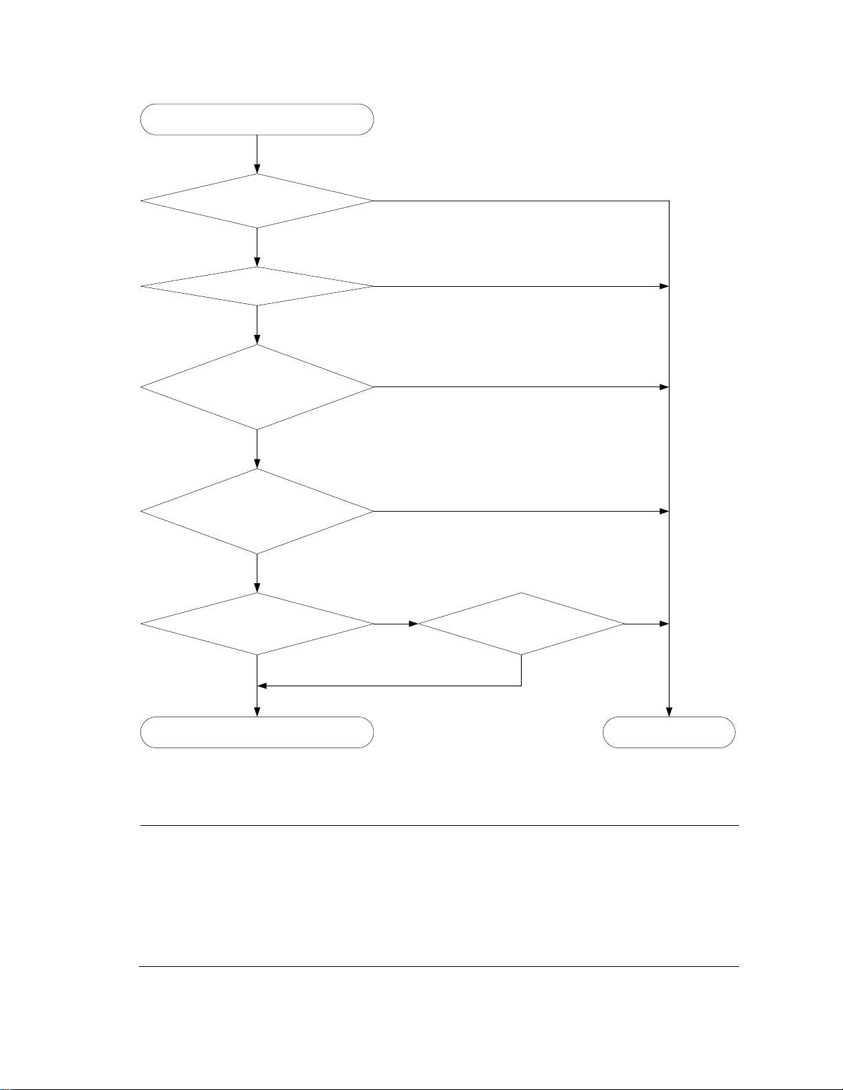
No
More candidate ports than allowed
max. number of Selected ports?
Is the port up?
Is there any hardware restriction?
Port number as low as to set
the port in the Selected state?
Set the aggregation state
of a member port
Set the port in the Selected state
Set the port in the
Unselected state
Yes
Yes
No
Yes
No
Yes
No Yes
No
Port attribute/class 2
configurations of the peer port
same as the peer port of the
reference port?
Yes
No
Port attribute/class 2
configurations same as the
reference port?
NOTE:
To ensure stable aggregation state and service continuity, do not change port attributes or class-two
configurations on any member port.
In a dynamic aggregation group, when the aggregation state of a local port changes, the aggregation state of
the peer port changes.
A port that joins a dynamic aggregation group after the Selected port limit has been reached will be placed in
the Selected state if it is more eligible for being selected than a current member port.
Figure 9 Setting the state of a member port in a dynamic aggregation group
Meanwhile, the system with the higher system ID, which has identified the aggregation state changes on
the remote system, sets the aggregation state of local member ports as the same as their peer ports.
35
Page 43

Task
Remarks
Configuring an aggregation group
Configuring a static aggregation group
Select either task
Configuring a dynamic aggregation group
Configuring an
aggregate
interface
Configuring the description of an aggregate interface
Optional
Enabling link state traps for an aggregate interface
Optional
Shutting down an aggregate interface
Optional
Configuring load
sharing for link
aggregation
groups
Configuring load-sharing criteria for link aggregation
groups
Optional
Enabling local-first load sharing for link aggregation
Optional
Enabling link-aggregation traffic redirection
Optional
Feature
Reference
RRPP
RRPP configuration in the High Availability Configuration Guide
MAC authentication
MAC authentication configuration in the Security Configuration Guide
Port security
Port security configuration in the Security Configuration Guide
IP source guard
IP source guard configuration in the Security Configuration Guide
802.1X
802.1X configuration in the Security Configuration Guide
Load-sharing criteria for link aggregation groups
In a link aggregation group, traffic can be load-shared across the selected member ports based on a set
of criteria, depending on your configuration.
You can choose one of the following criteria or any combination of them for load sharing:
MAC addresses
IP addresses
Service port numbers
Receiving port numbers
Ethernet link aggregation configuration task list
Complete the following tasks to configure Ethernet link aggregation:
Configuring an aggregation group
Configuration guidelines
You cannot assign a port to a Layer 2 aggregation group if any of the features listed in Table 6 is
configured on the port.
Table 6 Features incompatible with Layer 2 aggregation groups
36
Page 44

NOTE:
To achieve better load sharing results for data traffic among the member ports of a link aggregation
group, assign ports of the same type (such as all 100 Mbps ports or all GE ports and so on) to the link
aggregation group.
CAUTION:
Removing an aggregate interface also removes the corresponding aggregation group. At the same
time, all member ports leave the aggregation group.
NOTE:
To guarantee a successful static aggregation, ensure that the ports at both ends of each link are in the
same aggregation state.
To do...
Use the command...
Remarks
Enter system view
system-view
—
Create a Layer 2 aggregate
interface and enter Layer 2
aggregate interface view
interface bridge-aggregation
interface-number
Required
When you create a Layer 2
aggregate interface, the system
automatically creates a Layer 2
static aggregation group
numbered the same.
Exit to system view
quit
—
Enter Layer 2 Ethernet interface
view
interface interface-type interfacenumber
Required
Repeat these two steps to assign
multiple Layer 2 Ethernet
interfaces to the aggregation
group.
Assign the Ethernet interface to
the aggregation group
port link-aggregation group
number
NOTE:
To guarantee a successful dynamic aggregation, make sure that the peer ports of the ports aggregated
at one end are also aggregated. The two ends can automatically negotiate the aggregation state of
each member port.
To do...
Use the command...
Remarks
Enter system view
system-view
—
Configuring a static aggregation group
Follow these steps to configure a Layer 2 static aggregation group:
Configuring a dynamic aggregation group
Follow these steps to configure a Layer 2 dynamic aggregation group:
37
Page 45

To do...
Use the command...
Remarks
Set the system LACP priority
lacp system-priority system-priority
Optional
By default, the system LACP
priority is 32768.
Changing the system LACP
priority might affect the
aggregation state of the ports in a
dynamic aggregation group.
Create a Layer 2 aggregate
interface and enter Layer 2
aggregate interface view
interface bridge-aggregation
interface-number
Required
When you create a Layer 2
aggregate interface, the system
automatically creates a Layer 2
static aggregation group
numbered the same.
Configure the aggregation group
to work in dynamic aggregation
mode
link-aggregation mode dynamic
Required
By default, an aggregation group
works in static aggregation mode.
Exit to system view
quit
—
Enter Layer 2 Ethernet interface
view
interface interface-type interfacenumber
Required
Repeat these two steps to assign
more Layer 2 Ethernet interfaces
to the aggregation group.
Assign the Ethernet interface to
the aggregation group
port link-aggregation group
number
Assign the port an LACP priority
lacp port-priority port-priority
Optional
By default, the LACP priority of a
port is 32768.
Changing the LACP priority of a
port might affect the aggregation
state of the ports in the dynamic
aggregation group.
Set the LACP timeout interval on
the port to the short timeout
interval (1 second)
lacp period short
Optional
By default, the LACP timeout
interval on a port is the long
timeout interval (30 seconds).
NOTE:
Most of the configurations that can be performed on Layer 2 Ethernet interfaces can also be performed
on Layer 2 aggregate interfaces.
Configuring an aggregate interface
You can perform the following configurations on an aggregate interface:
Configuring the description of an aggregate interface
Enabling link state traps for an aggregate interface
Shutting down an aggregate interface
38
Page 46

To do...
Use the command...
Remarks
Enter system view
system-view
—
Enter Layer 2 aggregate
interface view
interface bridge-aggregation
interface-number
—
Configure the description of
the aggregate interface
description text
Optional
By default, the description of an
interface is interface-name Interface,
such as Bridge-Aggregation1 Interface.
To do...
Use the command...
Remarks
Enter system view
system-view
—
Enable the trap function
globally
snmp-agent trap enable [ standard [
linkdown | linkup ] * ]
Optional
By default, link state trapping is
enabled globally and on all
interfaces.
Enter Layer 2 aggregate
interface view
interface bridge-aggregation interfacenumber
—
Enable link state traps for the
aggregate interface
enable snmp trap updown
Optional
Enabled by default.
To do...
Use the command...
Remarks
Enter system view
system-view
—
Configuring the description of an aggregate interface
You can configure the description of an aggregate interface for administration purposes such as
describing the purpose of the interface.
Follow these steps to configure the description of an aggregate interface:
Enabling link state traps for an aggregate interface
You can configure an aggregate interface to generate linkUp trap messages when its link goes up and
linkDown trap messages when its link goes down. For more information, see the Network Management
and Monitoring Configuration Guide.
Follow these steps to enable link state traps on an aggregate interface:
Shutting down an aggregate interface
Shutting down or bringing up an aggregate interface affects the aggregation state and link state of ports
in the corresponding aggregation group in the following ways:
When an aggregate interface is shut down, all Selected ports in the aggregation group become
unselected and their link state becomes down.
When an aggregate interface is brought up, the aggregation state of ports in the aggregation
group is recalculated and their link state becomes up.
Follow these steps to shut down an aggregate interface:
39
Page 47

To do...
Use the command...
Remarks
Enter Layer 2 aggregate interface
view
interface bridge-aggregation
interface-number
—
Shut down the aggregate
interface
shutdown
Required
By default, aggregate
interfaces are up.
To do...
Use the command...
Remarks
Enter system view
system-view
—
Configure the global linkaggregation load-sharing
criteria
link-aggregation load-sharing mode {
destination-ip | destination-mac |
destination-port | ingress-port |
source-ip | source-mac | source-port }
*
Required
By default, the global linkaggregation load-sharing criteria
include the receiving port, source
MAC address, and destination
MAC address for Layer 2 packet
types such as ARP, and the source
and destination IP addresses for
Layer 3 packet types such as IP
packets.
Configuring load sharing for link aggregation groups
Configuring load-sharing criteria for link aggregation groups
You can determine how traffic is load-shared across a link aggregation group by configuring load-sharing
criteria. The criteria can be service port numbers, IP addresses, MAC addresses, receiving ports, or any
combination.
The switch supports configuring global and group-specific aggregation load-sharing criteria. A link
aggregation group preferentially uses group-specific load-sharing criteria. If no group-specific loadsharing criteria are available, the group uses the global load-sharing criteria.
Configuring the global link-aggregation load-sharing criteria
Follow these steps to configure global link-aggregation load-sharing criteria:
You can set the following global aggregation load-sharing criteria:
Source IP address
Destination IP address
Source MAC address
Destination MAC address
Source IP address and destination IP address
Source IP address and source port number
Destination IP address and destination port number
40
Page 48

To do…
Use the command…
Remarks
Enter system view
system-view
—
Enter aggregate interface
view
interface bridge-aggregation
interface-number
—
Configure the load-sharing
criteria for the aggregation
group
link-aggregation load-sharing mode
{ destination-ip | destination-mac |
source-ip | source-mac } *
Required
By default, an aggregation group
uses the global link-aggregation
load-sharing criteria.
CAUTION:
By default, an aggregation group uses the global link-aggregation load sharing criteria. You can
configure the group-specific link-aggregation load-sharing criteria to overwrite the global ones, except
those specified with the destination-port, source-port, or ingress-port keywords.
Any two or all three of these elements – ingress port number, source MAC address, and destination
MAC address
Configuring group-specific load-sharing criteria
Follow these steps to configure load-sharing criteria for a link aggregation group:
You can set the following group-specific load-sharing criteria:
Source IP address
Destination IP address
Source IP address and destination IP address
Source MAC address
Destination MAC address
Destination MAC address and source MAC address
Enabling local-first load sharing for link aggregation
Use the local-first load sharing mechanism in a cross-switch link aggregation scenario to distribute traffic
preferentially across all member ports on the ingress switch rather than all member ports.
When you aggregate ports on different member switches in an IRF fabric, you can use local-first load
sharing to reduce traffic on IRF links, as shown in Figure 10. For more information about IRF, see the IRF
Configuration Guide.
41
Page 49

Any member ports on
the ingress switch?
Local-first load sharing
mechanism enabled?
Yes No
Yes
No
The egress port for a traffic flow
is an aggregate interface that has
member ports on different IRF
member switches
Packets are load shared only
across the member ports on
the ingress switch
Packets are load shared
across all member ports
To do...
Use the command...
Remarks
Enter system view
system-view
—
Enable local-first load-sharing for
link aggregation
link-aggregation load-sharing
mode local-first
Optional
Enabled by default.
To do...
Use the command...
Remarks
Enter system view
system-view
—
Enable link-aggregation traffic
redirection
link-aggregation lacp traffic-redirectnotification enable
Optional
Disabled by default.
Figure 10 Local-first link-aggregation load sharing
Follow these steps to enable local-first load sharing for link aggregation:
Enabling link-aggregation traffic redirection
The link-aggregation traffic redirection function is available on IRF member switches. It can redirect traffic
between IRF member switches for a cross-device link aggregation group. Link-aggregation traffic
redirection prevents traffic interruption when you reboot an IRF member switch that contains link
aggregation member ports. For more information about IRF, see the IRF Configuration Guide.
Follow these steps to enable link-aggregation traffic redirection:
42
Page 50

CAUTION:
Link-aggregation traffic redirection applies only to dynamic link aggregation groups.
To prevent traffic interruption, enable link-aggregation traffic redirection on devices at both ends of the
aggregate link.
To prevent packet loss that might occur at a reboot, disable both MSTP and link-aggregation traffic redirection.
In an IRF fabric that adopts the ring connection, slight packet loss can occur when the IRF member switch
enabled with link-aggregation traffic redirection reboots. To prevent packet loss, you can enable local-first loadsharing for link aggregation on all IRF member switches (see ―Enabling local-first load sharing for link
aggregation‖).
To do...
Use the command...
Remarks
Display information for an
aggregate interface or multiple
aggregate interfaces
display interface bridge-aggregation [ brief [
down ] ] [ | { begin | exclude | include }
regular-expression ]
display interface bridge-aggregation interfacenumber [ brief ] [ | { begin | exclude | include
} regular-expression ]
Available in any
view
Display the local system ID
display lacp system-id [ | { begin | exclude |
include } regular-expression ]
Available in any
view
Display the global or groupspecific link-aggregation loadsharing criteria
display link-aggregation load-sharing mode [
interface [ bridge-aggregation interface-number
] ] [ | { begin | exclude | include } regular-
expression ]
Available in any
view
Display detailed link aggregation
information on link aggregation
member ports
display link-aggregation member-port [
interface-list ] [ | { begin | exclude | include }
regular-expression ]
Available in any
view
Display the summary of all
aggregation groups
display link-aggregation summary [ | { begin |
exclude | include } regular-expression ]
Available in any
view
Display detailed information
about a specific or all
aggregation groups
display link-aggregation verbose [ bridgeaggregation [ interface-number ] ] [ | { begin |
exclude | include } regular-expression ]
Available in any
view
Clear LACP statistics for a specific
or all link aggregation member
ports
reset lacp statistics [ interface interface-list ]
Available in user
view
Clear statistics for a specific or all
aggregate interfaces
reset counters interface [ bridge-aggregation [
interface-number ] ]
Available in user
view
Displaying and maintaining Ethernet link aggregation
Ethernet link aggregation configuration examples
43
Page 51

NOTE:
In an aggregation group, only ports that have the same port attributes and class-two configurations
(see ‖Configuration classes‖) as the reference port (see ―Reference port‖) can operate as Selected
ports. You must ensure that all member ports have the same port attributes and class-two configurations
as the reference port. The other settings only need to be configured on the aggregate interface, not on
the member ports.
GE1/0/2
GE1/0/1
GE1/0/3
Link aggregation 1
GE1/0/2
GE1/0/1
GE1/0/3
BAGG1 BAGG1
Device A Device B
VLAN 10
VLAN 20
GE1/0/4
GE1/0/5
VLAN 10
VLAN 20
GE1/0/4
GE1/0/5
Layer 2 static aggregation configuration example
Network requirements
As shown in Figure 11:
Device A and Device B are connected through their respective Layer 2 Ethernet interfaces
GigabitEthernet 1/0/1 through GigabitEthernet 1/0/3.
Configure a Layer 2 static link aggregation group on Device A and Device B, respectively. Enable
VLAN 10 at one end of the aggregate link to communicate with VLAN 10 at the other end, and
VLAN 20 at one end to communicate with VLAN 20 at the other end.
Enable traffic to be load-shared across aggregation group member ports based on source and
destination MAC addresses.
Figure 11 Network diagram for Layer 2 static aggregation
Configuration procedure
1. Configure Device A
# Create VLAN 10, and assign port GigabitEthernet 1/0/4 to VLAN 10.
<DeviceA> system-view
[DeviceA] vlan 10
[DeviceA-vlan10] port gigabitethernet 1/0/4
[DeviceA-vlan10] quit
# Create VLAN 20, and assign port GigabitEthernet 1/0/5 to VLAN 20.
[DeviceA] vlan 20
[DeviceA-vlan20] port gigabitethernet 1/0/5
[DeviceA-vlan20] quit
# Create Layer 2 aggregate interface Bridge-Aggregation 1.
44
Page 52

NOTE:
This configuration automatically propagates to all the member ports in link aggregation group 1.
[DeviceA] interface bridge-aggregation 1
[DeviceA-Bridge-Aggregation1] quit
# Assign ports GigabitEthernet 1/0/1 through GigabitEthernet 1/0/3 to link aggregation group 1.
[DeviceA] interface gigabitethernet 1/0/1
[DeviceA-GigabitEthernet1/0/1] port link-aggregation group 1
[DeviceA-GigabitEthernet1/0/1] quit
[DeviceA] interface gigabitethernet 1/0/2
[DeviceA-GigabitEthernet1/0/2] port link-aggregation group 1
[DeviceA-GigabitEthernet1/0/2] quit
[DeviceA] interface gigabitethernet 1/0/3
[DeviceA-GigabitEthernet1/0/3] port link-aggregation group 1
[DeviceA-GigabitEthernet1/0/3] quit
# Configure Layer 2 aggregate interface Bridge-Aggregation 1 as a trunk port and assign it to VLANs 10
and 20.
[DeviceA] interface bridge-aggregation 1
[DeviceA-Bridge-Aggregation1] port link-type trunk
[DeviceA-Bridge-Aggregation1] port trunk permit vlan 10 20
Please wait... Done.
Configuring GigabitEthernet1/0/1... Done.
Configuring GigabitEthernet1/0/2... Done.
Configuring GigabitEthernet1/0/3... Done.
[DeviceA-Bridge-Aggregation1] quit
# Configure the device to use the source and destination MAC addresses of packets as the global linkaggregation load-sharing criteria.
[DeviceA] link-aggregation load-sharing mode source-mac destination-mac
2. Configure Device B
Configure Device B as you configure Device A.
3. Verify the configurations
# Display the summary information about all aggregation groups on Device A.
[DeviceA] display link-aggregation summary
Aggregation Interface Type:
BAGG -- Bridge-Aggregation, RAGG -- Route-Aggregation
Aggregation Mode: S -- Static, D -- Dynamic
Loadsharing Type: Shar -- Loadsharing, NonS -- Non-Loadsharing
Actor System ID: 0x8000, 000f-e2ff-0001
AGG AGG Partner ID Select Unselect Share
Interface Mode Ports Ports Type
-------------------------------------------------------------------------------
BAGG1 S none 3 0 Shar
45
Page 53
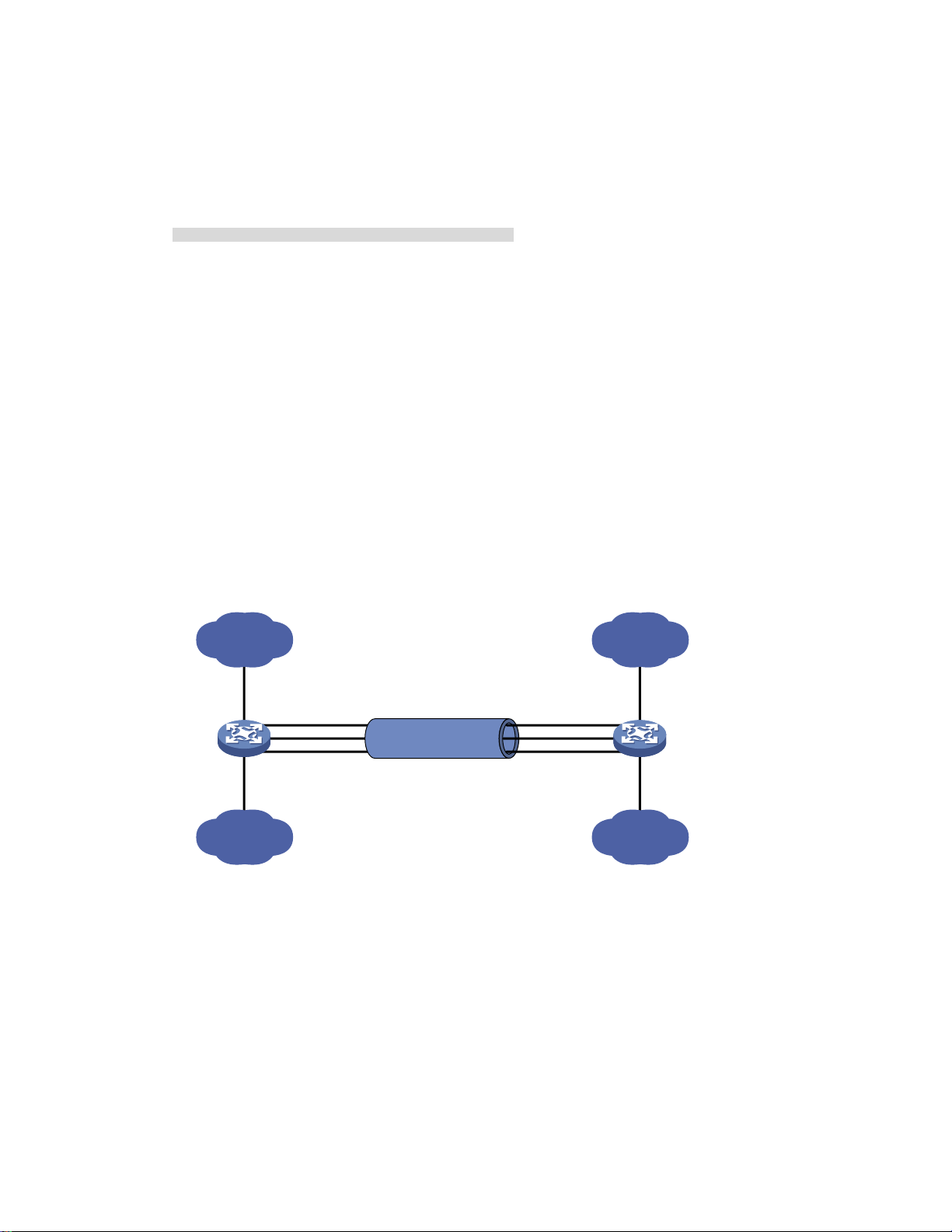
GE1/0/2
GE1/0/1
GE1/0/3
Link aggregation 1
GE1/0/2
GE1/0/1
GE1/0/3
BAGG1 BAGG1
Device A Device B
VLAN 10
VLAN 20
GE1/0/4
GE1/0/5
VLAN 10
VLAN 20
GE1/0/4
GE1/0/5
The output shows that link aggregation group 1 is a load-shared Layer 2 static aggregation group, and it
contains three Selected ports.
# Display the global link-aggregation load-sharing criteria on Device A.
[DeviceA] display link-aggregation load-sharing mode
Link-Aggregation Load-Sharing Mode:
destination-mac address, source-mac address
The output shows that all link aggregation groups created on the device perform load sharing based on
source and destination MAC addresses.
Layer 2 dynamic aggregation configuration example
Network requirements
As shown in Figure 12:
Device A and Device B are connected through their respective Layer 2 Ethernet interfaces
GigabitEthernet 1/0/1 through GigabitEthernet 1/0/3.
Configure a Layer 2 dynamic link aggregation group on Device A and Device B, respectively.
Enable VLAN 10 at one end of the aggregate link to communicate with VLAN 10 at the other end,
and VLAN 20 at one end to communicate with VLAN 20 at the other end.
Enable traffic to be load-shared across aggregation group member ports based on source and
destination MAC addresses.
Figure 12 Network diagram for Layer 2 dynamic aggregation
Configuration procedure
1. Configure Device A
# Create VLAN 10, and assign port GigabitEthernet 1/0/4 to VLAN 10.
<DeviceA> system-view
[DeviceA] vlan 10
[DeviceA-vlan10] port gigabitethernet 1/0/4
[DeviceA-vlan10] quit
# Create VLAN 20, and assign port GigabitEthernet 1/0/5 to VLAN 20.
[DeviceA] vlan 20
46
Page 54

NOTE:
This configuration automatically propagates to all the member ports in link aggregation group 1.
[DeviceA-vlan20] port gigabitethernet 1/0/5
[DeviceA-vlan20] quit
# Create Layer 2 aggregate interface Bridge-aggregation 1, and configure the link aggregation mode as
dynamic.
[DeviceA] interface bridge-aggregation 1
[DeviceA-Bridge-Aggregation1] link-aggregation mode dynamic
# Assign ports GigabitEthernet 1/0/1 through GigabitEthernet 1/0/3 to link aggregation group 1 one
at a time.
[DeviceA] interface gigabitethernet 1/0/1
[DeviceA-GigabitEthernet1/0/1] port link-aggregation group 1
[DeviceA-GigabitEthernet1/0/1] quit
[DeviceA] interface gigabitethernet 1/0/2
[DeviceA-GigabitEthernet1/0/2] port link-aggregation group 1
[DeviceA-GigabitEthernet1/0/2] quit
[DeviceA] interface gigabitethernet 1/0/3
[DeviceA-GigabitEthernet1/0/3] port link-aggregation group 1
[DeviceA-GigabitEthernet1/0/3] quit
# Configure Layer 2 aggregate interface Bridge-Aggregation 1 as a trunk port and assign it to VLANs 10
and 20.
[DeviceA] interface bridge-aggregation 1
[DeviceA-Bridge-Aggregation1] port link-type trunk
[DeviceA-Bridge-Aggregation1] port trunk permit vlan 10 20
Please wait... Done.
Configuring GigabitEthernet1/0/1... Done.
Configuring GigabitEthernet1/0/2... Done.
Configuring GigabitEthernet1/0/3... Done.
[DeviceA-Bridge-Aggregation1] quit
# Configure the device to use the source and destination MAC addresses of packets as the global linkaggregation load-sharing criteria.
[DeviceA] link-aggregation load-sharing mode source-mac destination-mac
2. Configure Device B
Configure Device B as you configure Device A.
3. Verify the configurations
# Display the summary information about all aggregation groups on Device A.
[DeviceA] display link-aggregation summary
Aggregation Interface Type:
BAGG -- Bridge-Aggregation, RAGG -- Route-Aggregation
Aggregation Mode: S -- Static, D -- Dynamic
Loadsharing Type: Shar -- Loadsharing, NonS -- Non-Loadsharing
Actor System ID: 0x8000, 000f-e2ff-0001
47
Page 55

GE1/0/2
GE1/0/1
GE1/0/3
Link aggregation 1
BAGG1 BAGG1
Device A Device B
Link aggregation 2
GE1/0/4
GE1/0/2
GE1/0/1
GE1/0/3
GE1/0/4
BAGG2 BAGG2
VLAN 10
VLAN 20
GE1/0/5
GE1/0/6
VLAN 10
VLAN 20
GE1/0/5
GE1/0/6
AGG AGG Partner ID Select Unselect Share
Interface Mode Ports Ports Type
-------------------------------------------------------------------------------
BAGG1 D 0x8000, 000f-e2ff-0002 3 0 Shar
The output shows that link aggregation group 1 is a load-shared Layer 2 dynamic aggregation group,
and it contains three Selected ports.
# Display the global link-aggregation load-sharing criteria on Device A.
[DeviceA] display link-aggregation load-sharing mode
Link-Aggregation Load-Sharing Mode:
destination-mac address, source-mac address
The output shows that all link aggregation groups created on the device perform load sharing based on
source and destination MAC addresses.
Layer 2 aggregation load sharing configuration example
Network requirements
As shown in Figure 13:
Device A and Device B are connected by their Layer 2 Ethernet interfaces GigabitEthernet 1/0/1
through GigabitEthernet 1/0/4.
Configure two Layer 2 static link aggregation groups (1 and 2) on Device A and Device B
respectively, and enable VLAN 10 at one end of the aggregate link to communicate with VLAN 10
at the other end through Bridge-Aggregation 1, and VLAN 20 at one end to communicate with
VLAN 20 at the other end through Bridge-Aggregation 2.
Configure the load sharing criterion for link aggregation group 1 as the source MAC addresses of
packets and the load sharing criterion for link aggregation group 2 as the destination MAC
addresses of packets to enable traffic to be load-shared across aggregation group member ports.
Figure 13 Network diagram for Layer 2 aggregation load sharing configuration
Configuration procedure
1. Configure Device A
# Create VLAN 10, and assign port GigabitEthernet 1/0/5 to VLAN 10.
<DeviceA> system-view
48
Page 56

NOTE:
This configuration automatically propagates to all the member ports in link aggregation group 1.
[DeviceA] vlan 10
[DeviceA-vlan10] port gigabitethernet 1/0/5
[DeviceA-vlan10] quit
# Create VLAN 20, and assign port GigabitEthernet 1/0/6 to VLAN 20.
<DeviceA> system-view
[DeviceA] vlan 20
[DeviceA-vlan20] port gigabitethernet 1/0/6
[DeviceA-vlan20] quit
# Create Layer 2 aggregate interface Bridge-Aggregation 1, and configure the load sharing criterion for
the link aggregation group as the source MAC addresses of packets.
[DeviceA] interface bridge-aggregation 1
[DeviceA-Bridge-Aggregation1] link-aggregation load-sharing mode source-mac
[DeviceA-Bridge-Aggregation1] quit
# Assign ports GigabitEthernet 1/0/1 and GigabitEthernet 1/0/2 to link aggregation group 1.
[DeviceA] interface gigabitethernet 1/0/1
[DeviceA-GigabitEthernet1/0/1] port link-aggregation group 1
[DeviceA-GigabitEthernet1/0/1] quit
[DeviceA] interface gigabitethernet 1/0/2
[DeviceA-GigabitEthernet1/0/2] port link-aggregation group 1
[DeviceA-GigabitEthernet1/0/2] quit
# Configure Layer 2 aggregate interface Bridge-Aggregation 1 as a trunk port and assign it to VLANs
10.
[DeviceA] interface bridge-aggregation 1
[DeviceA-Bridge-Aggregation1] port link-type trunk
[DeviceA-Bridge-Aggregation1] port trunk permit vlan 10
Please wait... Done.
Configuring GigabitEthernet1/0/1... Done.
Configuring GigabitEthernet1/0/2... Done.
[DeviceA-Bridge-Aggregation1] quit
# Create Layer 2 aggregate interface Bridge-Aggregation 2, and configure the load sharing criterion for
the link aggregation group as the destination MAC addresses of packets.
[DeviceA] interface bridge-aggregation 2
[DeviceA-Bridge-Aggregation2] link-aggregation load-sharing mode destination-mac
[DeviceA-Bridge-Aggregation2] quit
# Assign ports GigabitEthernet 1/0/3 and GigabitEthernet 1/0/4 to link aggregation group 2.
[DeviceA] interface gigabitethernet 1/0/3
[DeviceA-GigabitEthernet1/0/3] port link-aggregation group 2
[DeviceA-GigabitEthernet1/0/3] quit
[DeviceA] interface gigabitethernet 1/0/4
[DeviceA-GigabitEthernet1/0/4] port link-aggregation group 2
[DeviceA-GigabitEthernet1/0/4] quit
49
Page 57

# Configure Layer 2 aggregate interface Bridge-Aggregation 2 as a trunk port and assign it to VLANs
20.
[DeviceA] interface bridge-aggregation 2
[DeviceA-Bridge-Aggregation2] port link-type trunk
[DeviceA-Bridge-Aggregation2] port trunk permit vlan 20
Please wait... Done.
Configuring GigabitEthernet1/0/3... Done.
Configuring GigabitEthernet1/0/4... Done.
[DeviceA-Bridge-Aggregation2] quit
2. Configure Device B
Configure Device B as you configure Device A.
3. Verify the configurations
# Display the summary information about all aggregation groups on Device A.
[DeviceA] display link-aggregation summary
Aggregation Interface Type:
BAGG -- Bridge-Aggregation, RAGG -- Route-Aggregation
Aggregation Mode: S -- Static, D -- Dynamic
Loadsharing Type: Shar -- Loadsharing, NonS -- Non-Loadsharing
Actor System ID: 0x8000, 000f-e2ff-0001
AGG AGG Partner ID Select Unselect Share
Interface Mode Ports Ports Type
-------------------------------------------------------------------------------
BAGG1 S none 2 0 Shar
BAGG2 S none 2 0 Shar
The output shows that link aggregation groups 1 and 2 are both load-sharing-capable Layer 2 static
aggregation groups and each contains two Selected ports.
# Display all the group-specific load-sharing criteria on Device A.
[DeviceA] display link-aggregation load-sharing mode interface
Bridge-Aggregation1 Load-Sharing Mode:
source-mac address
Bridge-Aggregation2 Load-Sharing Mode:
destination-mac address
The output shows that the load sharing criterion for link aggregation group 1 is the source MAC
addresses of packets and that for link aggregation group 2 is the destination MAC addresses of packets.
50
Page 58

To do…
Use the command…
Remarks
Enter system view
system-view
—
Enter
interface
view or port
group view
Enter
Ethernet
interface
view
interface interface-type
interface-number
Required
Use one of the commands, as follows:
To assign an Ethernet port to the isolation
group, enter Ethernet interface view.
To assign a Layer 2 aggregate interface
to the isolation group, enter Layer 2
aggregate interface view. The subsequent
configuration applies to both the Layer 2
aggregate interface and all its member
ports.
To assign multiple Ethernet ports to the
isolation group in bulk, enter port group
view.
Enter Layer
2
aggregate
interface
view
interface bridge-aggregation
interface-number
Enter port
group view
port-group manual port-groupname
Assign the port or ports to
the isolation group
port-isolate enable
Required
The isolation group does not contain any
ports by default.
NOTE:
If the switch fails to apply the port-isolate enable command to a Layer 2 aggregate interface, it does
not assign any member port of the aggregate interface to the isolation group. If the failure occurs on a
member port, the switch can still assign other member ports to the isolation group.
Port isolation configuration
Introduction to port isolation
Assigning access ports to different VLANs is a typical way to isolate Layer 2 traffic for data privacy and
security, but this approach is demanding on VLAN resources. To isolate Layer 2 traffic without using
VLANs, HP introduced the port isolation feature.
To use the feature, you assign ports to a port isolation group. Ports in an isolation group are called
―isolated ports.‖ An isolated port does not forward any Layer 2 traffic to any other isolated port on the
same switch, even if they are in the same VLAN. Still, an isolated port can communicate with any other
port outside the isolation group, provided that they are in the same VLAN.
The A5120 EI Switch Series support one isolation group called ―isolation group 1.‖ This isolation group is
automatically created and cannot be deleted. There is no limit on the number of member ports.
Configuring the isolation group
Follow these steps to assign a port to the isolation group:
51
Page 59

To do…
Use the command…
Remarks
Display information about the isolation group
display port-isolate group [ | {
begin | exclude | include }
regular-expression ]
Available in any view
Internet
Host A Host B Host C
GE1/0/2
GE1/0/1
GE1/0/3
Device
GE1/0/4
Displaying and maintaining isolation groups
Port isolation configuration example
Network requirements
As shown in Figure 14:
Hosts A, B, and C are connected to port GigabitEthernet 1/0/1, GigabitEthernet 1/0/2, and
GigabitEthernet 1/0/3 of Device.
Device is connected to the Internet through GigabitEthernet 1/0/4.
GigabitEthernet 1/0/1, GigabitEthernet 1/0/2, GigabitEthernet 1/0/3, and GigabitEthernet
1/0/4 belong to the same VLAN.
Configure Device to enable Host A, Host B, and Host C to access the Internet when they are isolated from
one another.
Figure 14 Network diagram for port isolation configuration
Configuration procedure
# Assign ports GigabitEthernet 1/0/1, GigabitEthernet 1/0/2, and GigabitEthernet 1/0/3 to isolation
group 1.
<Device> system-view
[Device] interface gigabitethernet 1/0/1
[Device-GigabitEthernet1/0/1] port-isolate enable
[Device-GigabitEthernet1/0/1] quit
[Device] interface gigabitethernet 1/0/2
[Device-GigabitEthernet1/0/2] port-isolate enable
[Device-GigabitEthernet1/0/2] quit
[Device] interface gigabitethernet 1/0/3
52
Page 60

[Device-GigabitEthernet1/0/3] port-isolate enable
# Display information about the isolation group.
<Device> display port-isolate group
Port-isolate group information:
Uplink port support: NO
Group ID: 1
Group members:
GigabitEthernet1/0/1 GigabitEthernet1/0/2 GigabitEthernet1/0/3
53
Page 61

MSTP configuration
As a Layer 2 management protocol, the Spanning Tree Protocol (STP) eliminates Layer 2 loops by
selectively blocking redundant links in a network, putting them in a standby state, which still allows for
link redundancy.
The recent versions of STP are the Rapid Spanning Tree Protocol (RSTP) and the Multiple Spanning Tree
Protocol (MSTP). This document describes the features of STP, RSTP, and MSTP.
Introduction to STP
Why STP
STP was developed based on the 802.1d standard of IEEE to eliminate loops at the data link layer in a
local area network (LAN). Networks often have redundant links as backups in case of failures, but loops
are a very serious problem. Devices that run this protocol detect loops in the network by exchanging
information with one another, and eliminate loops by selectively blocking certain ports to prune the loop
structure into a loop-free tree structure. This avoids proliferation and infinite cycling of packets that would
occur in a loop network, and prevents received duplicate packets from decreasing the performance of
network devices.
In the narrow sense, STP refers to IEEE 802.1d STP. In the broad sense, STP refers to the IEEE 802.1d STP
and various enhanced spanning tree protocols derived from that protocol.
Protocol packets of STP
STP uses bridge protocol data units (BPDUs), also known as ―configuration messages‖, as its protocol
packets.
STP-enabled network devices exchange BPDUs to establish a spanning tree. BPDUs contain sufficient
information for the network devices to complete spanning tree calculation.
In STP, BPDUs have the following types:
Configuration BPDUs, used by network devices to calculate a spanning tree and maintain the
spanning tree topology
Topology change notification (TCN) BPDUs, which notify network devices of the network topology
changes
Configuration BPDUs contain sufficient information for the network devices to complete spanning tree
calculation. Important fields in a configuration BPDU include the following:
Root bridge ID: Consisting of the priority and MAC address of the root bridge.
Root path cost: Cost of the path to the root bridge denoted by the root identifier from the transmitting
bridge.
Designated bridge ID: Consisting of the priority and MAC address of the designated bridge.
Designated port ID: Consisting of the priority and global port number of the designated port.
Message age: Age of the configuration BPDU while it propagates in the network.
54
Page 62

Classification
Designated bridge
Designated port
For a device
A device directly connected to the local
device and responsible for forwarding
BPDUs to the local device
The port through which the
designated bridge forwards BPDUs
to this device
For a LAN
The device responsible for forwarding
BPDUs to this LAN segment
The port through which the
designated bridge forwards BPDUs
to this LAN segment
Max age: Maximum age of the configuration BPDU stored on the switch.
Hello time: Configuration BPDU transmission interval.
Forward delay: Delay that STP bridges use to transition port state.
Basic concepts in STP
Root bridge
A tree network must have a root bridge. The entire network contains only one root bridge. The root bridge
is not permanent, but can change along with changes of the network topology.
Upon initialization of a network, each device generates and periodically sends configuration BPDUs, with
itself as the root bridge. After network convergence, only the root bridge generates and periodically
sends configuration BPDUs, and the other devices forward the BPDUs.
Root port
On a non-root bridge, the port nearest to the root bridge is the root port. The root port is responsible for
communication with the root bridge. Each non-root bridge has only one root port. The root bridge has no
root port.
Designated bridge and designated port
Table 7 Description of designated bridges and designated ports
As shown in Figure 15, both Device B and Device C directly connect to the LAN. If Device A forwards
BPDUs to Device B through port A1, the designated bridge for Device B is Device A, and the designated
port of Device B is port A1 on Device A. If Device B forwards BPDUs to the LAN, the designated bridge
for the LAN is Device B, and the designated port for the LAN is port B2 on Device B.
55
Page 63

Device A
Device B Device C
Port A1 Port A2
Port B1 Port C1
Port B2 Port C2
LAN
NOTE:
The spanning tree calculation process described in the following sections is a simplified process for
example only.
Step
Description
1
A non-root device regards the port on which it received the optimum configuration BPDU
as the root port. For the selection of the optimum configuration BPDUs, see Table 9.
Path cost
Figure 15 A schematic diagram of designated bridges and designated ports
Path cost is a reference value used for link selection in STP. STP calculates path costs to select the most
robust links and block redundant links that are less robust, to prune the network into a loop-free tree.
How STP works
STP has the following workflow:
1. Initial state
Upon initialization of a device, each port generates a BPDU with the device as the root bridge, in which
the root path cost is 0, the designated bridge ID is the device ID, and the designated port is the port
itself.
2. Selection of the root bridge
Initially, each STP device on the network assumes itself to be the root bridge, with its own device ID as the
root bridge ID. By exchanging configuration BPDUs, the devices compare their root bridge IDs to elect the
device with the smallest root bridge ID as the root bridge.
3. Selection of the root port and designated ports
Table 8 Selection of the root port and designated ports
56
Page 64

Step
Description
2
Based on the configuration BPDU and the path cost of the root port, the device calculates
a designated port configuration BPDU for each of the other ports.
The root bridge ID is replaced with that of the configuration BPDU of the root port.
The root path cost is replaced with that of the configuration BPDU of the root port plus
the path cost of the root port.
The designated bridge ID is replaced with the ID of this device.
The designated port ID is replaced with the ID of this port.
3
The device compares the calculated configuration BPDU with the configuration BPDU on
the port whose port role will be defined, and acts depending on the result of the
comparison.
If the calculated configuration BPDU is superior, the device considers this port as the
designated port, replaces the configuration BPDU on the port with the calculated
configuration BPDU, and periodically sends the calculated configuration BPDU.
If the configuration BPDU on the port is superior, the device blocks this port without
updating its configuration BPDU. The blocked port can receive BPDUs but not send
BPDUs or forward data traffic.
NOTE:
When the network topology is stable, only the root port and designated ports forward traffic, and other
ports are all in the blocked state in which the port receive BPDUs but do not forward BPDUs or user
traffic.
Step
Actions
1
Upon receiving a configuration BPDU on a port, the device performs the following:
If the received configuration BPDU has a lower priority than that of the configuration
BPDU generated by the port, the device discards the received configuration BPDU and
keeps the configuration BPDU this port generated.
If the received configuration BPDU has a higher priority than that of the configuration
BPDU generated by the port, the device replaces the content of the configuration BPDU
generated by the port with the content of the received configuration BPDU.
2
The device compares the configuration BPDUs of all the ports and chooses the optimum
configuration BPDU.
NOTE:
The following are the principles of configuration BPDU comparison:
The configuration BPDU with the lowest root bridge ID has the highest priority.
If all configuration BPDUs have the same root bridge ID, their root path costs are compared. For example, the
root path cost in a configuration BPDU plus the path cost of a receiving port is S. The configuration BPDU with
the smallest S value has the highest priority.
If all configuration BPDUs have the same root path cost, their designated bridge IDs, designated port IDs, and
the IDs of the receiving ports are compared in sequence. The configuration BPDU that contains the smallest ID
wins.
Table 9 Selection of the optimum configuration BPDU
A tree topology forms upon successful election of the root bridge, the root port on each non-root bridge
and the designated ports.
57
Page 65
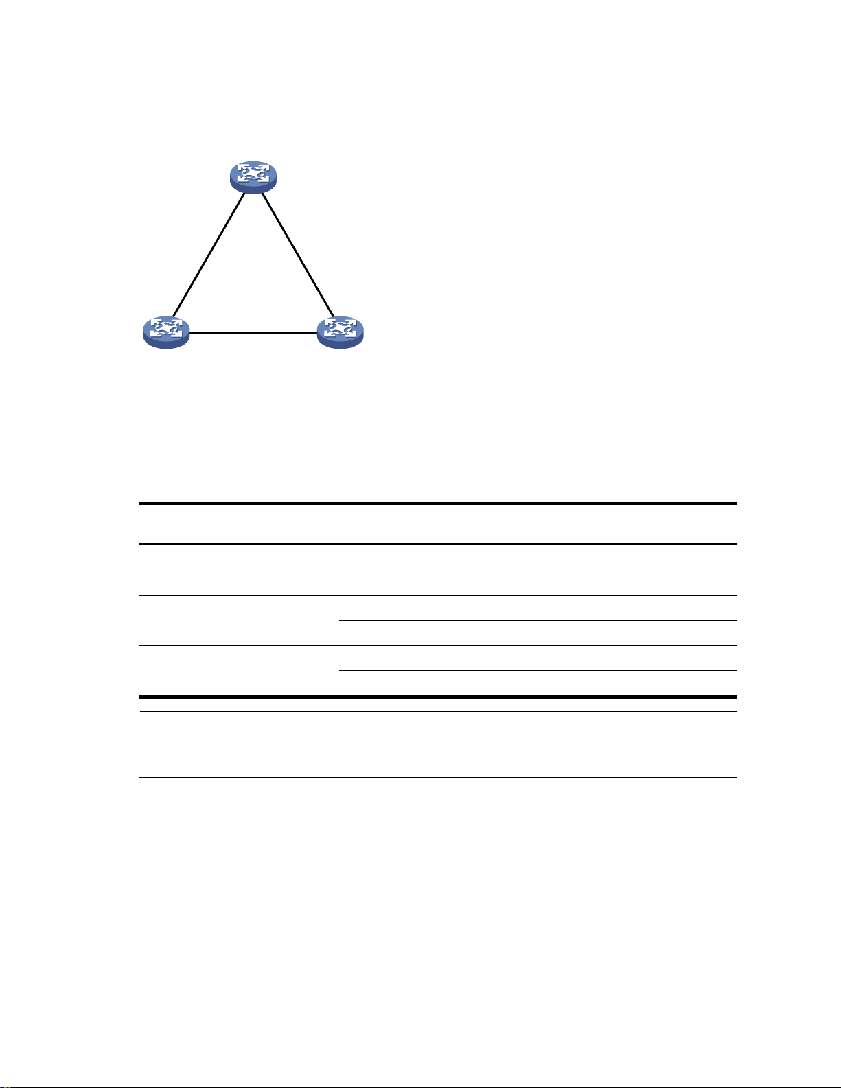
Device A
Priority = 0
Device B
Priority = 1
Device C
Priority = 2
Port A1 Port A2
Port B1
Port B2
Port C1
Port C2
P
ath cost
=
5
P
ath cost
=
10
Path cost = 4
Device
Port name
Configuration BPDU on the
port
Device A
Port A1
{0, 0, 0, Port A1}
Port A2
{0, 0, 0, Port A2}
Device B
Port B1
{1, 0, 1, Port B1}
Port B2
{1, 0, 1, Port B2}
Device C
Port C1
{2, 0, 2, Port C1}
Port C2
{2, 0, 2, Port C2}
NOTE:
In Table 10, each configuration BPDU contains the following fields: root bridge ID, root path cost,
designated bridge ID, and designated port ID.
Figure 16 provides an example of how the STP algorithm works.
Figure 16 Network diagram for the STP algorithm
As shown in Figure 16, the priority of Device A, Device B, and Device C is 0, 1, and 2 respectively, and
the path costs among these links are 5, 10, and 4 respectively.
4. Initial state of each device
Table 10 Initial state of each device
5. Comparison process and result on each device
58
Page 66

Device
Comparison process
Configuration BPDU on
ports after comparison
Device A
Port A1 receives the configuration BPDU of Port B1 {1,
0, 1, Port B1}, finds that its existing configuration BPDU
{0, 0, 0, Port A1} is superior to the received
configuration BPDU, and discards the received one.
Port A2 receives the configuration BPDU of Port C1 {2,
0, 2, Port C1}, finds that its existing configuration
BPDU {0, 0, 0, Port A2} is superior to the received
configuration BPDU, and discards the received one.
Device A finds that it is both the root bridge and
designated bridge in the configuration BPDUs of all its
ports, and considers itself as the root bridge. It does
not change the configuration BPDU of any port and
starts to periodically send configuration BPDUs.
Port A1: {0, 0, 0, Port
A1}
Port A2: {0, 0, 0, Port
A2}
Device B
Port B1 receives the configuration BPDU of Port A1 {0,
0, 0, Port A1}, finds that the received configuration
BPDU is superior to its existing configuration BPDU {1,
0, 1, Port B1}, and updates its configuration BPDU.
Port B2 receives the configuration BPDU of Port C2 {2,
0, 2, Port C2}, finds that its existing configuration
BPDU {1, 0, 1, Port B2} is superior to the received
configuration BPDU, and discards the received one.
Port B1: {0, 0, 0, Port
A1}
Port B2: {1, 0, 1, Port
B2}
Device B compares the configuration BPDUs of all its
ports, decides that the configuration BPDU of Port B1 is
the optimum, and selects Port B1 as the root port with
the configuration BPDU unchanged.
Based on the configuration BPDU and path cost of the
root port, Device B calculates a designated port
configuration BPDU for Port B2 {0, 5, 1, Port B2}, and
compares it with the existing configuration BPDU of
Port B2 {1, 0, 1, Port B2}. Device B finds that the
calculated one is superior, decides that Port B2 is the
designated port, replaces the configuration BPDU on
Port B2 with the calculated one, and periodically sends
the calculated configuration BPDU.
Root port (Port B1): {0,
0, 0, Port A1}
Designated port (Port
B2): {0, 5, 1, Port B2}
Device C
Port C1 receives the configuration BPDU of Port A2 {0,
0, 0, Port A2}, finds that the received configuration
BPDU is superior to its existing configuration BPDU {2,
0, 2, Port C1}, and updates its configuration BPDU.
Port C2 receives the original configuration BPDU of
Port B2 {1, 0, 1, Port B2}, finds that the received
configuration BPDU is superior to the existing
configuration BPDU {2, 0, 2, Port C2}, and updates its
configuration BPDU.
Port C1: {0, 0, 0, Port
A2}
Port C2: {1, 0, 1, Port
B2}
Table 11 Comparison process and result on each device
59
Page 67

Device
Comparison process
Configuration BPDU on
ports after comparison
Device C compares the configuration BPDUs of all its
ports, decides that the configuration BPDU of Port C1 is
the optimum, and selects Port C1 as the root port with
the configuration BPDU unchanged.
Based on the configuration BPDU and path cost of the
root port, Device C calculates the configuration BPDU
of Port C2 {0, 10, 2, Port C2}, and compares it with
the existing configuration BPDU of Port C2 {1, 0, 1, Port
B2}. Device C finds that the calculated configuration
BPDU is superior to the existing one, selects Port C2 as
the designated port, and replaces the configuration
BPDU of Port C2 with the calculated one.
Root port (Port C1): {0,
0, 0, Port A2}
Designated port (Port
C2): {0, 10, 2, Port
C2}
Port C2 receives the updated configuration BPDU of
Port B2 {0, 5, 1, Port B2}, finds that the received
configuration BPDU is superior to its existing
configuration BPDU {0, 10, 2, Port C2}, and updates
its configuration BPDU.
Port C1 receives a periodic configuration BPDU {0, 0,
0, Port A2} from Port A2, finds that it is the same as the
existing configuration BPDU, and discards the received
one.
Port C1: {0, 0, 0, Port
A2}
Port C2: {0, 5, 1, Port
B2}
Device C finds that the root path cost of Port C1 (10)
(root path cost of the received configuration BPDU (0)
plus path cost of Port C1 (10 )) is larger than that of Port
C2 (9) (root path cost of the received configuration
BPDU (5) plus path cost of Port C2 (4)), decides that
the configuration BPDU of Port C2 is the optimum, and
selects Port C2 as the root port with the configuration
BPDU unchanged.
Based on the configuration BPDU and path cost of the
root port, Device C calculates a designated port
configuration BPDU for Port C1 {0, 9, 2, Port C1} and
compares it with the existing configuration BPDU of
Port C1 {0, 0, 0, Port A2}. Device C finds that the
existing configuration BPDU is superior to the
calculated one and blocks Port C1 with the
configuration BPDU unchanged. Then Port C1 does not
forward data until a new event triggers a spanning tree
calculation process, for example, the link between
Device B and Device C is down.
Blocked port (Port C1):
{0, 0, 0, Port A2}
Root port (Port C2):
{0, 5, 1, Port B2}
NOTE:
In Table 11, each configuration BPDU contains the following fields: root bridge ID, root path cost,
designated bridge ID, and designated port ID.
After the comparison processes described in Table 11, a spanning tree with Device A as the root bridge is
established, and the topology is shown in Figure 17.
60
Page 68

A
B C
Root port
Designated port
Root bridge
Normal link
Blocked link
Blocked port
Figure 17 Topology of the final calculated spanning tree
The BPDU forwarding mechanism in STP
STP forwards configuration BPDUs following these guidelines:
Upon network initiation, every switch regards itself as the root bridge, generates configuration
BPDUs with itself as the root, and sends the configuration BPDUs at a regular hello interval.
If the root port received a configuration BPDU and the received configuration BPDU is superior to the
configuration BPDU of the port, the device increases the message age carried in the configuration
BPDU following a certain rule and starts a timer to time the configuration BPDU while sending this
configuration BPDU through the designated port.
STP timers
If the configuration BPDU received on a designated port has a lower priority than the configuration
BPDU of the local port, the port immediately sends its own configuration BPDU in response.
If a path becomes faulty, the root port on this path no longer receives new configuration BPDUs and
the old configuration BPDUs will be discarded because of timeout. The device generates a
configuration BPDU with itself as the root and sends the BPDUs and TCN BPDUs. This triggers a new
spanning tree calculation process to establish a new path to restore the network connectivity.
However, the newly calculated configuration BPDU cannot be propagated throughout the network
immediately, so the old root ports and designated ports that have not detected the topology change
continue forwarding data along the old path. If the new root ports and designated ports begin to forward
data as soon as they are elected, a temporary loop might occur.
The most important timing parameters in STP calculation are forward delay, hello time, and max age.
Forward delay: Specifies the delay time for port state transition. A path failure can cause spanning
tree re-calculation to adapt the spanning tree structure to the change. However, the resulting new
configuration BPDU cannot propagate throughout the network immediately. If the newly elected root
ports and designated ports start to forward data immediately, a temporary loop will likely occur. For
this reason, as a mechanism for state transition in STP, the newly elected root ports or designated
ports require twice the forward delay time before they transit to the forwarding state to ensure that
the new configuration BPDU has propagated throughout the network.
Hello time: Specifies the time interval at which a device sends hello packets to the surrounding
devices to ensure that the paths are fault-free.
Max age: Determines whether a configuration BPDU held by the device has expired. A
configuration BPDU beyond the max age is discarded.
61
Page 69

NOTE:
In RSTP, a newly elected root port can enter the forwarding state rapidly if the old root port on the device has
stopped forwarding data and the upstream designated port has started forwarding data.
In RSTP, a newly elected designated port can enter the forwarding state rapidly if the designated port is an edge
port (a port that directly connects to a user terminal rather than to another device or a shared LAN segment) or
a port connected to a point-to-point link. If the designated port is an edge port, it can enter the forwarding state
directly. If the designated port is connected to a point-to-point link, it can enter the forwarding state immediately
after the device undergoes handshake with the downstream device and gets a response.
Introduction to RSTP
Developed based on the 802.1w standard of IEEE, RSTP is an optimized version of STP. It achieves rapid
network convergence by allowing a newly elected root port or designated port to enter the forwarding
state much faster under certain conditions than STP.
Introduction to MSTP
Why MSTP
Limitations of STP and RSTP
STP does not support rapid state transition of ports. A newly elected root port or designated port must
wait twice the forward delay time before it transits to the forwarding state, even if it is a port on a pointto-point link or an edge port.
Although RSTP supports rapid network convergence, it has the same drawback as STP—All bridges within
a LAN share the same spanning tree, so redundant links cannot be blocked based on VLAN, and the
packets of all VLANs are forwarded along the same spanning tree.
Features of MSTP
Developed based on IEEE 802.1s, MSTP overcomes the limitations of STP and RSTP. In addition to
supporting for rapid network convergence, it provides a better load sharing mechanism for redundant
links by allowing data flows of different VLANs to be forwarded along separate paths. For more
information about VLANs, see the chapter ―VLAN configuration.‖
MSTP provides the following features:
MSTP supports mapping VLANs to spanning tree instances by means of a VLAN-to-instance
mapping table. MSTP can reduce communication overheads and resource usage by mapping
multiple VLANs to one instance.
MSTP divides a switched network into multiple regions, each of which contains multiple spanning
trees that are independent of one another.
MSTP prunes a loop network into a loop-free tree, which avoids proliferation and endless cycling of
packets in a loop network. In addition, it supports load balancing of VLAN data by providing
multiple redundant paths for data forwarding.
MSTP is compatible with STP and RSTP.
62
Page 70

MST region 1
MST region 2 MST region 3
MST region 4
VLAN 1 à MSTI 1
VLAN 2 à MSTI 2
Other VLANs à MSTI 0
VLAN 1 à MSTI 1
VLAN 2 à MSTI 2
Other VLANs à MSTI 0
VLAN 1 à MSTI 1
VLAN 2 à MSTI 2
Other VLANs à MSTI 0
VLAN 1 à MSTI 1
VLAN 2&3 à MSTI 2
Other VLANs à MSTI 0
CST
MST region 3
Device A
Device C
Device B
Device D
VLAN 1 à MSTI 1
VLAN 2&3 à MSTI 2
Other VLANs à MSTI 0
To MST region 4
To MST region 2
BA
C D
MSTI 1
A B
C D
MSTI 0
B
D
MSTI 2
C
A
Regional root
MSTI
Topology of MSTIs in MST region 3
Basic concepts in MSTP
Figure 18 Basic concepts in MSTP
Figure 19 Network diagram and topology of MST region 3
As shown in Figure 18, a switched network comprises four MST regions, and each MST region comprises
four devices running MSTP. Figure 19 shows the networking topology of MST region 3.
63
Page 71

MST region
A multiple spanning tree region (MST region) consists of multiple devices in a switched network and the
network segments among them. All these devices have the following characteristics:
MSTP-enabled
Same region name
Same VLAN-to-instance mapping configuration
Same MSTP revision level configuration
Physically linked with one another
Multiple MST regions can exist in a switched network. You can assign multiple devices to the same MST
region. In Figure 18, the switched network comprises four MST regions, MST region 1 through MST region
4, and all devices in each MST region have the same MST region configuration.
MSTI
MSTP can generate multiple independent spanning trees in an MST region, and each spanning tree is
mapped to the specific VLANs. Each spanning tree is referred to as a ―multiple spanning tree instance
(MSTI).‖
In Figure 19, for example, MST region 3 comprises three MSTIs, MSTI 1, MSTI 2, and MSTI 0.
VLAN-to-instance mapping table
CST
IST
CIST
As an attribute of an MST region, the VLAN-to-instance mapping table describes the mapping
relationships between VLANs and MSTIs.
In Figure 19, for example, the VLAN-to-instance mapping table of MST region 3 is: VLAN 1 to MSTI 1,
VLAN 2 and VLAN 3 to MSTI 2, and other VLANs to MSTI 0. MSTP achieves load balancing by means
of the VLAN-to-instance mapping table.
The common spanning tree (CST) is a single spanning tree that connects all MST regions in a switched
network. If you regard each MST region as a device, the CST is a spanning tree calculated by these
devices through STP or RSTP.
For example, the blue lines in Figure 18 represent the CST.
An internal spanning tree (IST) is a spanning tree that runs in an MST region. It is a special MSTI, and is
also called ―MSTI 0.‖ All VLANs are mapped to MSTI 0 by default. As shown in Figure 18, MSTI 0 is the
IST in MST region 3.
Jointly constituted by ISTs and the CST, the common and internal spanning tree (CIST) is a single
spanning tree that connects all devices in a switched network. ISTs in all MST regions and the CST jointly
constitute the CIST of the entire network. In Figure 18, for example, the ISTs in all MST regions plus the
inter-region CST constitute the CIST of the entire network.
Regional root
The root bridge of the IST or an MSTI within an MST region is the regional root of the IST or MSTI. Based
on the topology, different spanning trees in an MST region might have different regional roots.
For example, in MST region 3 in Figure 19, the regional root of MSTI 1 is Device B, the regional root of
MSTI 2 is Device C, and the regional root of MSTI 0 (also known as the IST) is Device A.
64
Page 72

Device A
(Root bridge)
Port A1 Port A2
Root port
Designated port
Normal link
Blocked link
Alternate port
Backup port
Master port
Boundary port
Device C
Device B Device D
Port A3 Port A4
Port B1
Port B2 Port B3
Port C1
Port C2
Port C3 Port C4
Port D1
Port D2
MST region
To the common root
To other MST regions
Edge port
Port D3
Common root bridge
The common root bridge is the root bridge of the CIST.
In Figure 18, for example, the common root bridge is a device in MST region 1.
Roles of ports
A port can play different roles in different MSTIs. As shown in Figure 20, an MST region comprises
Device A, Device B, Device C, and Device D. Port A1 and port A2 of Device A connect to the common
root bridge. Port B2 and Port B3 of Device B form a loop. Port C3 and Port C4 of Device C connect to
other MST regions. Port D3 of Device D directly connects to a host.
Figure 20 Port roles
MSTP calculation involves the following port roles:
Root port: Forwards data for a non-root bridge to the root bridge. The root bridge does not have
any root port.
Designated port: Forwards data to the downstream network segment or device.
Alternate port: The backup port for a root port or master port. When the root port or master port is
blocked, the alternate port takes over.
Backup port: The backup port of a designated port. When the designated port fails, the backup port
takes over. When a loop occurs because of the interconnection of two ports of the same MSTP
device, the device blocks either of the two ports, and the blocked port is the backup port.
Edge port: An edge port does not connect to any network device or network segment, but directly
connects to a user host.
Master port: A port on the shortest path from the local MST region to the common root bridge. The
master port is a root port on the IST or CIST and still a master port on the other MSTIs.
Boundary port: Connects an MST region to another MST region or to an STP/RSTP-running device.
In MSTP calculation, a boundary port’s role on an MSTI is consistent with its role on the CIST. But
that is not true with master ports. A master port on MSTIs is a root port on the CIST.
65
Page 73

NOTE:
When in different MSTIs, a port can be in different states.
Port role (right)
Root port/master
port
Designated port
Alternate port
Backup port
Port state
(below)
Forwarding
√ √ — — Learning
√ √ —
—
Discarding
√ √ √
√
Port states
In MSTP, a port can be in one of the following states:
Forwarding: The port receives and sends BPDUs, obtains MAC addresses, and forwards user traffic.
Learning: The port receives and sends BPDUs, obtains MAC addresses, but does not forward user
Discarding: The port receives and sends BPDUs, but does not obtain MAC addresses or forward
A port state is not exclusively associated with a port role. Table 12 lists the port states that each port role
supports. (A check mark [√] indicates that the port supports this state, while a dash [—] indicates that the
port does not support this state.)
Table 12 Port states that different port roles support
traffic. Learning is an intermediate port state.
user traffic.
How MSTP works
MSTP divides an entire Layer 2 network into multiple MST regions, which are connected by a calculated
CST. Inside an MST region, multiple spanning trees are calculated. Each spanning tree is an MSTI.
Among these MSTIs, MSTI 0 is the IST. Like STP, MSTP uses configuration BPDUs to calculate spanning
trees. An important difference is that an MSTP BPDU carries the MSTP configuration on the bridge from
which the BPDU is sent.
CIST calculation
The calculation of a CIST tree is also the process of configuration BPDU comparison. During this process,
the device with the highest priority is elected as the root bridge of the CIST. MSTP generates an IST within
each MST region through calculation. At the same time, MSTP regards each MST region as a single
device and generates a CST among these MST regions through calculation. The CST and ISTs constitute
the CIST of the entire network.
MSTI calculation
Within an MST region, MSTP generates different MSTIs for different VLANs based on the VLAN-toinstance mappings. For each spanning tree, MSTP performs a separate calculation process, which is
similar to spanning tree calculation in STP. For more information, see ―How STP works.‖
In MSTP, a VLAN packet is forwarded along the following paths:
Within an MST region, the packet is forwarded along the corresponding MSTI.
Between two MST regions, the packet is forwarded along the CST.
66
Page 74

Task
Remarks
Configuring the root
bridge
Configuring an MST region
Required
Configuring the root bridge or a secondary root bridge
Optional
Configuring the work mode of an MSTP device
Optional
Configuring the priority of a device
Optional
Configuring the maximum hops of an MST region
Optional
Configuring the network diameter of a switched network
Optional
Configuring timers of MSTP
Optional
Configuring the timeout factor
Optional
Configuring the maximum port rate
Optional
Configuring ports as edge ports
Optional
Configuring the link type of ports
Optional
Configuring the mode a port uses to recognize/send MSTP
packets
Optional
Implementation of MSTP on devices
MSTP is compatible with STP and RSTP. Devices that are running MSTP and that are used for spanning
tree calculation can identify STP and RSTP protocol packets.
In addition to basic MSTP functions, the following functions are provided for ease of management:
Root bridge hold
Root bridge backup
Root guard
BPDU guard
Loop guard
TC-BPDU guard
BPDU drop
Protocols and standards
MSTP is documented in the following protocols and standards:
IEEE 802.1d: Media Access Control (MAC) Bridges
IEEE 802.1w: Part 3: Media Access Control (MAC) Bridges—Amendment 2: Rapid Reconfiguration
IEEE 802.1s: Virtual Bridged Local Area Networks—Amendment 3: Multiple Spanning Trees
MSTP configuration task list
Before configuring MSTP, you must plan the role of each device in each MSTI, root bridge or leaf node,
and then configure the devices as planned. In each MSTI, only one device acts as the root bridge, and all
others act as leaf nodes.
Complete these tasks to configure MSTP:
67
Page 75

Task
Remarks
Enabling the output of port state transition information
Optional
Enabling the MSTP feature
Required
Configuring the leaf
nodes
Configuring an MST region
Required
Configuring the work mode of an MSTP device
Optional
Configuring the timeout factor
Optional
Configuring the maximum port rate
Optional
Configuring ports as edge ports
Optional
Configuring path costs of ports
Optional
Configuring port priority
Optional
Configuring the link type of ports
Optional
Configuring the mode a port uses to recognize/send MSTP
packets
Optional
Enabling the output of port state transition information
Optional
Enabling the MSTP feature
Required
Performing mCheck
Optional
Configuring Digest Snooping
Optional
Configuring No Agreement Check
Optional
Configuring protection functions
Optional
NOTE:
If GVRP and MSTP are enabled on a device at the same time, GVRP packets are forwarded along the CIST. To
advertise a certain VLAN within the network through GVRP, be sure that this VLAN is mapped to the CIST (MSTI
0) when you configure the VLAN-to-instance mapping table. For more information about GVRP, see the chapter
―GVRP configuration.‖
MSTP is mutually exclusive with any of the following functions on a port: RRPP, Smart Link, and BPDU tunneling.
Configurations made in system view take effect globally. Configurations made in Ethernet interface view take
effect on the current interface only. Configurations made in port group view take effect on all member ports in
the port group. Configurations made in Layer 2 aggregate interface view take effect only on the aggregate
interface. Configurations made on an aggregation member port can take effect only after the port is removed
from the aggregation group.
After you enable MSTP on a Layer 2 aggregate interface, the system performs MSTP calculation on the Layer 2
aggregate interface but not on the aggregation member ports. The MSTP enable state and forwarding state of
each selected port in an aggregation group is consistent with those of the corresponding Layer 2 aggregate
interface.
Though the member ports of an aggregation group do not participate in MSTP calculation, the ports still reserve
their MSTP configurations for participating in MSTP calculation after leaving the aggregation group.
68
Page 76

To do...
Use the command...
Remarks
Enter system view
system-view
—
Enter MST region view
stp region-configuration
—
Configure the MST region name
region-name name
Optional
The MST region name is the MAC
address by default.
Configure the VLAN-to-instance
mapping table
instance instance-id vlan vlan-list
Optional
Use either command.
All VLANs in an MST region are
mapped to the CIST (or MSTI 0)
by default.
vlan-mapping modulo modulo
Configure the MSTP revision level
of the MST region
revision-level level
Optional
0 by default.
Display the MST region
configurations that are not
activated yet
check region-configuration
Optional
Activate MST region configuration
manually
active region-configuration
Required
Display the activated
configuration information of the
MST region
display stp region-configuration [
| { begin | exclude | include }
regular-expression ]
Optional
Available in any view
NOTE:
Two or more MSTP-enabled devices belong to the same MST region only if they are configured to have the same
format selector (0 by default, not configurable), MST region name, VLAN-to-instance mapping entries in the MST
region, and MST region revision level, and they are connected via a physical link.
The configuration of MST region–related parameters, especially the VLAN-to-instance mapping table, will cause
MSTP to begin a new spanning tree calculation process, which might result in network topology instability. To
reduce the possibility of topology instability caused by configuration, MSTP does not immediately begin a new
spanning tree calculation process when it is processing MST region–related configurations. Instead, such
configurations takes effect only after you activate the MST region–related parameters by using the active region-
configuration command, or enable MSTP by using the stp enable command if MSTP is disabled.
Configuring MSTP
Configuring an MST region
Make the following configurations on the root bridge and on the leaf nodes separately.
Follow these steps to configure an MST region:
Configuring the root bridge or a secondary root bridge
You can have MSTP determine the root bridge of a spanning tree through MSTP calculation, or you can
specify the current device as the root bridge or as a secondary root bridge using the commands that the
system provides.
69
Page 77

To do...
Use the command...
Remarks
Enter system view
system-view
—
Configure the current device as
the root bridge of a specific
spanning tree
stp [ instance instance-id ] root
primary
Required
By default, a device does not
function as the root bridge of any
spanning tree.
To do...
Use the command...
Remarks
Enter system view
system-view
—
Configure the current device as a
secondary root bridge of a
specific spanning tree
stp [ instance instance-id ] root
secondary
Required
By default, a device does not
function as a secondary root
bridge.
NOTE:
After specifying the current device as the root bridge or a secondary root bridge, you cannot change the priority
of the device.
Alternatively, you can configure the current device as the root bridge by setting the priority of the device to 0. For
the device priority configuration, see ―Configuring the priority of a device.‖
Note the following rules:
A device has independent roles in different MSTIs. It can act as the root bridge or a secondary root
bridge of one MSTI and the root bridge or a secondary root bridge of another MSTI. However, one
device cannot be the root bridge and a secondary root bridge in the same MSTI at the same time.
There is only one root bridge in effect in a spanning tree instance. If two or more devices have been
designated as root bridges of the same spanning tree instance, MSTP selects the device with the
lowest MAC address as the root bridge.
When the root bridge of an instance fails or is shut down, the secondary root bridge (if you have
specified one) can take over the role of the primary root bridge. However, if you specify a new
primary root bridge for the instance then, the one you specify, not the secondary root bridge will
become the root bridge. If you have specified multiple secondary root bridges for an instance, when
the root bridge fails, MSTP will select the secondary root bridge with the lowest MAC address as the
new root bridge.
Configuring the current device as the root bridge of a specific spanning tree
Follow these steps to configure the current device as the root bridge of a specific spanning tree:
Configuring the current device as a secondary root bridge of a specific spanning tree
Follow these steps to configure the current device as a secondary root bridge of a specific spanning tree:
Configuring the work mode of an MSTP device
MSTP and RSTP are mutually compatible and can recognize each other’s protocol packets. However, STP
cannot recognize MSTP packets. For hybrid networking with legacy STP devices, and for full
interoperability with RSTP-enabled devices, MSTP supports the following work modes: STP-compatible
mode, RSTP mode, and MSTP mode.
In STP-compatible mode, all ports of the device send STP BPDUs,
70
Page 78

To do...
Use the command...
Remarks
Enter system view
system-view
—
Configure the work mode of
MSTP
stp mode { stp | rstp | mstp }
Required
MSTP mode by default.
To do...
Use the command...
Remarks
Enter system view
system-view
—
Configure the priority of the
current device in a specified MSTI
stp [ instance instance-id ] priority
priority
Required
32768 by default.
CAUTION:
You cannot change the priority of a device after it is configured as the root bridge or as a secondary root
bridge.
During root bridge selection, if all devices in a spanning tree have the same priority, the one with the lowest
MAC address will be selected as the root bridge of the spanning tree.
In RSTP mode, all ports of the device send RSTP BPDUs. If the device detects that it is connected to a
legacy STP device, the port that connects to the legacy STP device will automatically migrate to STPcompatible mode.
In MSTP mode, all ports of the device send MSTP BPDUs. If the device detects that it is connected to
a legacy STP device, the port that connects to the legacy STP device will automatically migrate to
STP-compatible mode.
Make this configuration on the root bridge and on the leaf nodes separately.
Follow these steps to configure the MSTP work mode:
Configuring the priority of a device
Priority is a factor in spanning tree calculation. The priority of a device determines whether it can be
elected as the root bridge of a spanning tree. A lower numeric value indicates a higher priority. You can
set the priority of a device to a low value to specify the device as the root bridge of the spanning tree. An
MSTP-enabled device can have different priorities in different MSTIs.
Make this configuration on the root bridge only.
Follow these steps to configure the priority of a device in a specified MSTI:
Configuring the maximum hops of an MST region
By setting the maximum hops of an MST region, you can restrict the region size. The maximum hops
configured on the regional root bridge will be used as the maximum hops of the MST region.
Configuration BPDUs sent by the regional root bridge always have a hop count set to the maximum value.
When a switch receives this configuration BPDU, it decrements the hop count by 1, and uses the new hop
count in the BPDUs that it propagates. When the hop count of a BPDU reaches 0, it is discarded by the
device that received it. Devices beyond the reach of the maximum hop can no longer participate in
spanning tree calculation, so the size of the MST region is limited.
Make this configuration on the root bridge only. All devices other than the root bridge in the MST region
use the maximum hop value set for the root bridge.
71
Page 79

To do...
Use the command...
Remarks
Enter system view
system-view
—
Configure the maximum hops of
the MST region
stp max-hops hops
Required
20 by default.
To do...
Use the command...
Remarks
Enter system view
system-view
—
Configure the network diameter of
the switched network
stp bridge-diameter diameter
Required
7 by default.
NOTE:
Based on the network diameter you configured, MSTP automatically sets an optimal hello time, forward delay,
and max age for the device.
In MSTP mode, each MST region is considered as a device. The network diameter configuration is effective only
for the CIST (or the common root bridge), but not for MSTIs.
Follow these steps to configure the maximum number of hops of an MST region:
Configuring the network diameter of a switched network
Any two terminal devices in a switched network are connected through a specific path composed of a
series of devices. The network diameter is the number of devices on the path composed of the most
devices. The network diameter is a parameter that indicates the network size. A bigger network diameter
indicates a larger network size.
Make this configuration on the root bridge only.
Follow these steps to configure the network diameter of a switched network:
Configuring timers of MSTP
STP calculation involves the following timing parameters.
Forward delay: Determines the time interval of port state transition. To prevent temporary loops, a
port must go through an intermediate state, the learning state, before it transitions from the
discarding state to the forwarding state, and must wait a certain period of time (forward delay)
before it transitions from one state to another to keep synchronized with the remote device during
state transition.
Hello time: Used to detect link failures. STP sends configuration BPDUs at the interval of hello time. If
a device fails to receive configuration BPDUs within the hello time, a new spanning tree calculation
process will be triggered because of configuration BPDU timeout.
Max age: Used to detect configuration BPDU timeout. In the CIST, the device uses the max age
parameter to determine whether a configuration BPDU received on a port has expired. If a port
receives a configuration BPDU that has expired, that MSTI must be re-calculated. The max age is
meaningless for MSTIs.
To avoid frequent network changes, be sure that the settings of the hello time, forward delay and max
age timers meet the following formulas:
2 × (forward delay – 1 second) max age
72
Page 80

To do...
Use the command...
Remarks
Enter system view
system-view
—
Configure the forward delay timer
stp timer forward-delay time
Optional
1500 centiseconds (15 seconds)
by default.
Configure the hello timer
stp timer hello time
Optional
200 centiseconds (2 seconds) by
default.
Configure the max age timer
stp timer max-age time
Optional
2000 centiseconds (20 seconds)
by default.
NOTE:
The length of the forward delay is related to the network diameter of the switched network. The larger the
network diameter is, the longer the forward delay should be. If the forward delay is too short, temporary
redundant paths might occur. If the forward delay is too long, network convergence might take a long time. HP
recommends that you use the default setting.
An appropriate hello time enables the device to quickly detect link failures on the network without using excessive
network resources. If the hello time is set too long, the device will mistake packet loss as a link failure and trigger
a new spanning tree calculation process. If the hello time is set too short, the device will frequently send repeated
configuration BPDUs, which adds to the device burden and wastes network resources. HP recommends that you
use the default setting.
If the max age time is too short, the network devices will frequently begin spanning tree calculations and might
mistake network congestion as a link failure. If the max age is too long, the network might fail to quickly detect
link failures and fail to quickly begin spanning tree calculations, reducing the auto-sensing capability of the
network. HP recommends that you use the default setting.
Max age 2 × (hello time + 1 second)
HP does not recommend you to manually set the timers. Instead, you can use the stp bridge-diameter
command to set the network diameter, and let the network automatically adjust the three timers according
to the network size. When the network diameter is the default value, the three timers are also set to their
defaults.
Make this configuration on the common root bridge only, and then this configuration applies to all
devices on the entire switched network.
Follow these steps to configure the timers of MSTP:
Configuring the timeout factor
The timeout factor is a parameter used to decide the timeout time in the following formula: Timeout time =
timeout factor × 3 × hello time.
After the network topology is stabilized, each non-root-bridge device forwards configuration BPDUs to the
downstream devices at the interval of hello time to determine whether any link is faulty. If a device does
not receive a BPDU from the upstream device within nine times the hello time, it assumes that the
upstream device has failed and starts a new spanning tree calculation process.
Sometimes a device might fail to receive a BPDU from the upstream device because the upstream device
is busy. If a spanning tree calculation occurs, the calculation can fail and also waste network resources.
73
Page 81

To do...
Use the command...
Remarks
Enter system view
system-view
—
Configure the timeout factor of the device
stp timer-factor factor
Required
3 by default.
To do...
Use the command...
Remarks
Enter system view
system-view
—
Enter interface
view or port
group view
Enter Ethernet interface
view or Layer 2
aggregate interface view
interface interface-type
interface-number
Required
Use either command.
Enter port group view
port-group manual port-groupname
Configure the maximum rate of the ports
stp transmit-limit limit
Required
10 by default.
NOTE:
The higher the maximum port rate is, the more BPDUs will be sent within each hello time, and the more
system resources will be used. By setting an appropriate maximum port rate, you can limit the rate at
which the port sends BPDUs and prevent MSTP from using excessive network resources when the
network becomes unstable. HP recommends that you use the default setting.
To do...
Use the command...
Remarks
Enter system view
system-view
—
In a stable network, you can avoid such unwanted spanning tree calculations by setting the timeout factor
to 5, 6, or 7.
Follow these steps to configure the timeout factor:
Configuring the maximum port rate
The maximum rate of a port refers to the maximum number of BPDUs the port can send within each hello
time. The maximum rate of a port is related to the physical status of the port and the network structure.
Make this configuration on the root bridge and on the leaf nodes separately.
Follow these steps to configure the maximum rate of a port or a group of ports:
Configuring ports as edge ports
If a port directly connects to a user terminal rather than another device or a shared LAN segment, this
port is regarded as an edge port. When a network topology change occurs, an edge port will not cause
a temporary loop. Because a device does not determine whether a port is directly connected to a
terminal, you must manually configure the port as an edge port. After that, the port can transition rapidly
from the blocked state to the forwarding state.
Make this configuration on the root bridge and on the leaf nodes separately.
Follow these steps to specify a port or a group of ports as edge port or ports:
74
Page 82

To do...
Use the command...
Remarks
Enter interface
view or port
group view
Enter Ethernet interface
view or Layer 2 aggregate
interface view
interface interface-type
interface-number
Required
Use either command.
Enter port group view
port-group manual portgroup-name
Configure the current ports as edge ports
stp edged-port enable
Required
All ports are non-edge ports
by default.
NOTE:
If BPDU guard is disabled, a port set as an edge port will become a non-edge port again if it receives a BPDU
from another port. To restore the edge port, re-enable it.
If a port directly connects to a user terminal, configure it as an edge port and enable BPDU guard for it. This
enables the port to transition to the forwarding state quickly while ensuring network security.
Among loop guard, root guard and edge port settings, only one function (whichever is configured the earliest)
can at a time take effect on a port.
To do...
Use the command...
Remarks
Enter system view
system-view
—
Specify a standard for the device
to use when it calculates the
default path costs of its ports
stp pathcost-standard { dot1d1998 | dot1t | legacy }
Optional
By default, the device calculates
the default path cost for ports
based on a private standard.
CAUTION:
If you change the standard that the device uses to calculate the default path costs, you restore the path
costs to the default.
Configuring path costs of ports
Path cost is a parameter related to the rate of a port. On an MSTP-enabled device, a port can have
different path costs in different MSTIs. Setting appropriate path costs allows VLAN traffic flows to be
forwarded along different physical links, achieving VLAN-based load balancing.
You can have the device automatically calculate the default path cost, or you can configure the path cost
for ports.
Make the following configurations on the leaf nodes only.
Specifying a standard that the device uses when it calculates the default path cost
You can specify a standard for the device to use in automatic calculation for the default path cost. The
device supports the following standards:
dot1d-1998—The device calculates the default path cost for ports based on IEEE 802.1d-1998.
dot1t—The device calculates the default path cost for ports based on IEEE 802.1t.
legacy—The device calculates the default path cost for ports based on a private standard.
Follow these steps to specify a standard for the device to use when it calculates the default path cost:
75
Page 83

Link speed
Port type
Path cost
IEEE 802.1d1998
IEEE 802.1t
Private standard
0 — 65535
200,000,000
200,000
10 Mbps
Single Port
100
2,000,000
2,000
Aggregate interface
containing 2 selected
ports
1,000,000
1,800
Aggregate interface
containing 3 selected
ports
666,666
1,600
Aggregate interface
containing 4 selected
ports
500,000
1,400
100 Mbps
Single Port
19
200,000
200
Aggregate interface
containing 2 selected
ports
100,000
180
Aggregate interface
containing 3 selected
ports
66,666
160
Aggregate interface
containing 4 selected
ports
50,000
140
1000 Mbps
Single Port
4
20,000
20
Aggregate interface
containing 2 selected
ports
10,000
18
Aggregate interface
containing 3 selected
ports
6666
16
Aggregate interface
containing 4 selected
ports
5000
14
10 Gbps
Single Port
2
2000
2
Aggregate interface
containing 2 selected
ports
1000
1
Aggregate interface
containing 3 selected
ports
666
1
Table 13 shows the mappings between the link speed and the path cost.
Table 13 Mappings between the link speed and the path cost
76
Page 84

Link speed
Port type
Path cost
IEEE 802.1d1998
IEEE 802.1t
Private standard
Aggregate interface
containing 4 selected
ports
500
1
NOTE:
When calculating path cost for an aggregate interface, IEEE 802.1d-1998 does not take into account
the number of selected ports in its aggregation group as IEEE 802.1t does. The calculation formula of
IEEE 802.1t is: Path cost = 200,000,000/link speed (in 100 kbps), where link speed is the sum of the
link speed values of the selected ports in the aggregation group.
To do...
Use the command...
Remarks
Enter system view
system-view
—
Enter interface
view or port
group view
Enter Ethernet interface
view or Layer 2
aggregate interface view
interface interface-type
interface-number
Required
Use either command.
Enter port group view
port-group manual portgroup-name
Configure the path cost of the ports
stp [ instance instance-id ]
cost cost
Required
By default, MSTP
automatically calculates the
path cost of each port.
CAUTION:
When the path cost of a port changes, MSTP re-calculates the role of the port and initiates a state
transition.
Configuring path costs of ports
Follow these steps to configure the path cost of ports:
Configuration example
# Specify that the device uses IEEE 802.1d-1998 to calculate the default path costs of its ports.
<Sysname> system-view
[Sysname] stp pathcost-standard dot1d-1998
# Set the path cost of GigabitEthernet 1/0/3 on MSTI 2 to 200.
<Sysname> system-view
[Sysname] interface gigabitethernet 1/0/3
[Sysname-GigabitEthernet1/0/3] stp instance 2 cost 200
Configuring port priority
The priority of a port is an important factor in determining whether the port can be elected as the root
port of a device. If all other conditions are the same, the port with the highest priority will be elected as
the root port.
77
Page 85

To do...
Use the command...
Remarks
Enter system view
system-view
—
Enter interface
view or port
group view
Enter Ethernet interface
view or Layer 2
aggregate interface view
interface interface-type
interface-number
Required
Use either command.
Enter port group view
port-group manual portgroup-name
Configure the port priority
stp [ instance instance-id ]
port priority priority
Required
128 for all ports by default.
NOTE:
When the priority of a port changes, MSTP re-calculates the role of the port and initiates a state transition.
A lower priority value indicates a higher priority. If you configure the same priority value for all the ports on a
device, the specific priority of a port depends on the index number of the port. A lower index number means a
higher priority. Changing the priority of a port triggers a new spanning tree calculation process.
To do...
Use the command...
Remarks
Enter system view
system-view
—
Enter interface
view or port
group view
Enter Ethernet
interface view or
Layer 2 aggregate
interface view
interface interface-type
interface-number
Required
Use either command.
Enter port group view
port-group manual port-groupname
Configure the link type of ports
stp point-to-point { auto |
force-false | force-true }
Required
By default, the port
automatically detects whether
its link is point-to-point.
On an MSTP-enabled device, a port can have different priorities in different MSTIs, and the same port
can play different roles in different MSTIs, so that data of different VLANs can be propagated along
different physical paths, implementing per-VLAN load balancing. You can set port priority values based
on the actual networking requirements.
Make this configuration on the leaf nodes only.
Follow these steps to configure the priority of a port or a group of ports:
Configuring the link type of ports
A point-to-point link is a link that directly connects two devices. If the two ports across a point-to-point link
are root ports or designated ports, the ports can rapidly transition to the forwarding state after a
proposal-agreement handshake process.
Make this configuration on the root bridge and on the leaf nodes separately.
Follow these steps to configure the link type of a port or a group of ports:
78
Page 86

NOTE:
If the current port is a Layer 2 aggregate interface or if it works in full duplex mode, you can configure the link to
which the current port connects as a point-to-point link. HP recommends that you use the default setting, and let
MSTP detect the link status automatically.
If you configure a port as connecting to a point-to-point link or a non-point-to-point link, the setting takes effect
for the port in all MSTIs.
If the physical link to which the port connects is not a point-to-point link and you manually set it to be one, your
configuration might cause temporary loops.
To do...
Use the command...
Remarks
Enter system view
system-view
—
Enter interface
view or port
group view
Enter Ethernet interface
view or Layer 2
aggregate interface
view
interface interface-type
interface-number
Required
Use either command.
Enter port group view
port-group manual portgroup-name
Configure the mode that the port uses to
recognize/send MSTP packets
stp compliance { auto | dot1s
| legacy }
Required
auto by default.
NOTE:
MSTP provides the MSTP packet format incompatibility guard function. In MSTP mode, if a port is configured to
recognize/send MSTP packets in a mode other than auto, and if it receives a packet in a format different from
the specified type, the port becomes a designated port and remains in the discarding state to prevent the
occurrence of a loop.
MSTP provides the MSTP packet format frequent change guard function. If a port receives MSTP packets of
different formats frequently, the MSTP packet format configuration can contain errors. If the port is working in
MSTP mode, it will be disabled for protection. Only network administrators can restore those closed ports.
Configuring the mode a port uses to recognize/send MSTP packets
A port can receive/send MSTP packets in the following formats:
dot1s—802.1s-compliant standard format, and
legacy—Compatible format
By default, the packet format recognition mode of a port is auto. The port automatically distinguishes the
two MSTP packet formats, and determines the format of packets that it will send based on the recognized
format.
You can configure the MSTP packet format on a port. When working in MSTP mode after the
configuration, the port sends and receives only MSTP packets of the format that you have configured to
communicate with devices that send packets of the same format.
Make this configuration on the root bridge and on the leaf nodes separately.
Follow these steps to configure the MSTP packet format to be supported on a port or a group of ports:
79
Page 87

To do...
Use the command...
Remarks
Enter system view
system-view
—
Enable output of port state
transition information
stp port-log { all | instance
instance-id }
Required
Enabled by default.
To do...
Use the command...
Remarks
Enter system view
system-view
—
Enable the MSTP feature globally
stp enable
Required
MSTP is globally disabled by
default.
Enter interface
view or port
group view
Enter Ethernet
interface view or
Layer 2 aggregate
interface view
interface interface-type
interface-number
Required
Use either command.
Enter port group
view
port-group manual port-groupname
Enable the MSTP feature for the ports
stp enable
Optional
By default, MSTP is enabled for
all ports after it is enabled for
the device globally.
NOTE:
In system view, you can use the stp enable or undo stp enable command to enable or disable STP globally.
You can use the undo stp enable command to disable the MSTP feature for certain ports so that they will not
participate in spanning tree calculation to save the CPU resources of the device.
Enabling the output of port state transition information
A large-scale, MSTP-enabled network can have many MSTIs, and ports might frequently transition from
one state to another. In this situation, you can enable devices to output the port state transition
information of all MSTIs or the specified MSTI in order to monitor the port states in real time.
Make this configuration separately on the root bridge and on the leaf nodes.
Follow these steps to enable output of port state transition information:
Enabling the MSTP feature
You must enable MSTP for the device before any other MSTP-related configurations can take effect.
Make this configuration on the root bridge and on the leaf nodes separately.
Follow these steps to enable the MSTP feature:
Performing mCheck
MSTP has three working modes: STP compatible mode, RSTP mode, and MSTP mode.
80
Page 88

To do...
Use the command...
Remarks
Enter system view
system-view
—
Perform mCheck
stp mcheck
Required
To do...
Use the command...
Remarks
Enter system view
system-view
—
Enter Ethernet interface view or Layer 2
aggregate interface view
interface interface-type
interface-number
—
Perform mCheck
stp mcheck
Required
NOTE:
An mCheck operation takes effect on a device only when MSTP operates in RSTP or MSTP mode.
NOTE:
Before you enable Digest Snooping, ensure that associated devices of different vendors are connected
and run MSTP.
If a port on a device that is running MSTP (or RSTP) connects to a device that is running STP, this port
automatically migrates to the STP-compatible mode. However, it will not be able to automatically migrate
back to the MSTP (or RSTP) mode, but will remain working in the STP-compatible mode under the
following circumstances:
The device that is running STP is shut down or removed.
The device that is running STP migrates to the MSTP (or RSTP) mode.
You can perform an mCheck operation to force the port to migrate to the MSTP (or RSTP) mode.
The following two methods for performing mCheck produce the same results.
Performing mCheck globally
Follow these steps to perform global mCheck:
Performing mCheck in interface view
Follow these steps to perform mCheck in interface view:
Configuring Digest Snooping
As defined in IEEE 802.1s, connected devices are in the same region only when their MST region-related
configurations (region name, revision level, VLAN-to-instance mappings) are identical. An MSTP-enabled
device identifies devices in the same MST region by determining the configuration ID in BPDU packets.
The configuration ID includes the region name, revision level, configuration digest, which is in 16-byte
length and is the result calculated via the HMAC-MD5 algorithm based on VLAN-to-instance mappings.
Because MSTP implementations vary with vendors, the configuration digests calculated via private keys
are different. The different vendors’ devices in the same MST region can not communicate with each
other.
Enabling the Digest Snooping feature on the port that connects the local device to a third-party device in
the same MST region can make the two devices communicate with each other.
81
Page 89

To do...
Use the command...
Remarks
Enter system view
system-view
—
Enter interface
view or port
group view
Enter Ethernet
interface view or
Layer 2 aggregate
interface view
interface interface-type interfacenumber
Required
Use either command.
Enter port group
view
port-group manual port-groupname
Enable Digest Snooping on the interface
or port group
stp config-digest-snooping
Required
Disabled by default.
Return to system view
quit
—
Enable global Digest Snooping
stp config-digest-snooping
Required
Disabled by default.
CAUTION:
With digest snooping enabled, in-the-same-region verification does not require comparison of configuration
digest, so the VLAN-to-instance mappings must be the same on associated ports.
With global Digest Snooping enabled, modification of VLAN-to-instance mappings and removal of the current
region configuration via the undo stp region-configuration command are not allowed. You can modify only the
region name and revision level.
To make Digest Snooping take effect, you must enable Digest Snooping both globally and on associated ports.
HP recommends that you enable Digest Snooping on all associated ports first and then enable it globally. This
will make the configuration take effect on all configured ports and reduce impact on the network.
To avoid loops, do not enable Digest Snooping on MST region edge ports.
HP recommends that you enable Digest Snooping first and then MSTP. To avoid causing traffic interruption, do
not configure Digest Snooping when the network is already working well.
Configuring the Digest Snooping feature
You can enable Digest Snooping only on a device that is connected to a third-party device that uses its
private key to calculate the configuration digest.
Follow these steps to configure Digest Snooping:
Digest Snooping configuration example
1. Network requirements
As shown in Figure 21:
Device A and Device B connect to Device C, which is a third-party device. All these devices are in
the same region.
Enable Digest Snooping on the ports of Device A and Device B that connect Device C, so that the
three devices can communicate with one another.
82
Page 90

Device C
(Root bridge)
GE1/0/1 GE1/0/2
GE1/0/1
GE1/0/2
GE1/0/1
GE1/0/2
Root port
Designated port
Normal link
Blocked link
Blocked port
Device A Device B
MST region
Figure 21 Digest Snooping configuration
2. Configuration procedure
# Enable Digest Snooping on GigabitEthernet 1/0/1 of Device A and enable global Digest Snooping on
Device A.
<DeviceA> system-view
[DeviceA] interface gigabitethernet 1/0/1
[DeviceA-GigabitEthernet1/0/1] stp config-digest-snooping
[DeviceA-GigabitEthernet1/0/1] quit
[DeviceA] stp config-digest-snooping
# Enable Digest Snooping on GigabitEthernet 1/0/1 of Device B and enable global Digest Snooping on
Device B.
<DeviceB> system-view
[DeviceB] interface gigabitethernet 1/0/1
[DeviceB-GigabitEthernet1/0/1] stp config-digest-snooping
[DeviceB-GigabitEthernet1/0/1] quit
[DeviceB] stp config-digest-snooping
Configuring No Agreement Check
In RSTP and MSTP, the following types of messages are used for rapid state transition on designated
ports:
Proposal—Sent by designated ports to request rapid transition
Agreement—Used to acknowledge rapid transition requests
Both RSTP and MSTP devices can perform rapid transition on a designated port only when the port
receives an agreement packet from the downstream device. RSTP and MSTP devices have the following
differences:
For MSTP, the root port of the downstream device sends an agreement packet only after it receives
an agreement packet from the upstream device.
For RSTP, the downstream device sends an agreement packet regardless of whether an agreement
packet from the upstream device is received.
Figure 22 shows the rapid state transition mechanism on MSTP designated ports.
83
Page 91

Root port Designated port
Upstream device Downstream device
(1) Proposal for rapid transition
(3) Agreement
The root port blocks non-edge
ports.
The root port changes to the
forwarding state and sends an
Agreement to the upstream
device.
(2) Agreement
The designated port
changes to the
forwarding state.
Root port Designated port
Upstream device Downstream device
(1) Proposal for rapid transition
(2) Agreement
The root port blocks non-edge
ports, changes to the forwarding
state, and sends an Agreement to
the upstream device.
The designated
port changes to the
forwarding state.
Figure 22 Rapid state transition of an MSTP designated port
Figure 23 shows rapid state transition of an RSTP designated port.
Figure 23 Rapid state transition of an RSTP designated port
Configuration prerequisites
Configuring the No Agreement Check function
If the upstream device is a third-party device, the rapid state transition implementation might be limited.
For example, when the upstream device uses a rapid transition mechanism similar to that of RSTP, and the
downstream device adopts MSTP and does not work in RSTP mode, the root port on the downstream
device receives no agreement packet from the upstream device and sends no agreement packets to the
upstream device. As a result, the designated port of the upstream device fails to transit rapidly, and can
only change to the forwarding state after a period twice the Forward Delay.
You can enable the No Agreement Check feature on the downstream device’s port to enable the
designated port of the upstream device to transit its state rapidly.
Before you configure the No Agreement Check function, complete the following tasks:
Connect a device is to a third-party upstream device that supports MSTP via a point-to-point link.
Configure the same region name, revision level and VLAN-to-instance mappings on the two devices,
assigning them to the same region.
To make the No Agreement Check feature take effect, enable it on the root port.
Follow these steps to configure No Agreement Check:
84
Page 92

To do...
Use the command...
Remarks
Enter system view
system-view
—
Enter interface
or port group
view
Enter Ethernet interface
view or Layer 2
aggregate interface
view
interface interface-type
interface-number
Required
Use either command.
Enter port group view
port-group manual port-groupname
Enable No Agreement Check
stp no-agreement-check
Required
Disabled by default.
GE1/0/1
Device A Device B
GE1/0/1
Root port Designated port
Root bridge
No Agreement Check configuration example
1. Network requirements
As shown in Figure 24:
Device A connects to Device B, a third-party device that has different MSTP implementation. Both
devices are in the same region.
Device B is the regional root bridge, and Device A is the downstream device.
Figure 24 No Agreement Check configuration
2. Configuration procedure
# Enable No Agreement Check on GigabitEthernet 1/0/1 of Device A.
<DeviceA> system-view
[DeviceA] interface gigabitethernet 1/0/1
[DeviceA-GigabitEthernet1/0/1] stp no-agreement-check
Configuring protection functions
An MSTP-enabled device supports the following protection functions:
BPDU guard
Root guard
Loop guard
TC-BPDU guard
BPDU drop
Configuration prerequisites
MSTP has been correctly configured on the device.
85
Page 93

To do...
Use the command...
Remarks
Enter system view
system-view
—
Enable the BPDU guard function
for the device
stp bpdu-protection
Required
Disabled by default.
NOTE:
BPDU guard does not take effect on loopback testing-enabled ports. For more information about
loopback testing, see the chapter ―Ethernet interface configuration.‖
To do...
Use the command...
Remarks
Enter system view
system-view
—
Enter interface
view or port
group view
Enter Ethernet interface
view or Layer 2 aggregate
interface view
interface interface-type
interface-number
Required
Use either command.
Enabling BPDU guard
For access layer devices, the access ports can directly connect to the user terminals (such as PCs) or file
servers. The access ports are configured as edge ports to allow rapid transition. When these ports receive
configuration BPDUs, the system automatically sets these ports as non-edge ports and starts a new
spanning tree calculation process. This causes a change of network topology. Under normal conditions,
these ports should not receive configuration BPDUs. However, if someone forges configuration BPDUs
maliciously to attack the devices, the network will become unstable.
MSTP provides the BPDU guard function to protect the system against such attacks. With the BPDU guard
function enabled on the devices, when edge ports receive configuration BPDUs, MSTP closes these ports
and notifies the NMS that these ports have been closed by MSTP. The device will reactivate the closed
ports after a detection interval. For more information about this detection interval, see the Fundamentals
Configuration Guide.
Make this configuration on a device with edge ports configured.
Follow these steps to enable BPDU guard:
Enabling root guard
The root bridge and secondary root bridge of a spanning tree should be located in the same MST region.
Especially for the CIST, the root bridge and secondary root bridge are put in a high-bandwidth core
region during network design. However, because of possible configuration errors or malicious attacks in
the network, the legal root bridge might receive a configuration BPDU with a higher priority. Another
device will supersede the current legal root bridge, causing an undesired change of the network
topology. The traffic that should go over high-speed links is switched to low-speed links, resulting in
network congestion.
To prevent this situation, MSTP provides the root guard function. If the root guard function is enabled on a
port of a root bridge, this port will keep playing the role of designated port on all MSTIs. After this port
receives a configuration BPDU with a higher priority from an MSTI, it immediately sets that port to the
listening state in the MSTI, without forwarding the packet. This is equivalent to disconnecting the link
connected to this port in the MSTI. If the port receives no BPDUs with a higher priority within twice the
forwarding delay, it reverts to its original state.
Make this configuration on a designated port.
Follow these steps to enable root guard:
86
Page 94

To do...
Use the command...
Remarks
Enter port group view
port-group manual portgroup-name
Enable the root guard function for the port(s)
stp root-protection
Required
Disabled by default.
NOTE:
Among loop guard, root guard and edge port settings, only one function (whichever is configured the
earliest) can at a time take effect on a port.
To do...
Use the command...
Remarks
Enter system view
system-view
—
Enter interface
view or port
group view
Enter Ethernet interface view
or Layer 2 aggregate
interface view
interface interface-type
interface-number
Required
Use either command.
Enter port group view
port-group manual portgroup-name
Enable the loop guard function for the ports
stp loop-protection
Required
Disabled by default.
NOTE:
Do not enable loop guard on a port that connects user terminals. Otherwise, the port will stay in the discarding
state in all MSTIs because it cannot receive BPDUs.
Among loop guard, root guard and edge port settings, only one function (whichever is configured the earliest)
can at a time take effect on a port.
Enabling loop guard
By continuing to receive BPDUs from the upstream device, a device can maintain the state of the root port
and blocked ports. However, because of link congestion or unidirectional link failures, these ports might
fail to receive BPDUs from the upstream devices. The device will reselect the port roles: Those ports in
forwarding state that failed to receive upstream BPDUs will become designated ports, and the blocked
ports will transition to the forwarding state, resulting in loops in the switched network. The loop guard
function can suppress the occurrence of such loops.
The initial state of a loop guard-enabled port is discarding in every MSTI. When the port receives BPDUs,
its state transitions normally. Otherwise, it stays in the discarding state to prevent temporary loops.
Make this configuration on the root port and alternate ports of a device.
Follow these steps to enable loop guard:
Enabling TC-BPDU guard
When a switch receives topology change (TC) BPDUs (the BPDUs that notify devices of topology
changes), the switch flushes its forwarding address entries. If someone forges TC-BPDUs to attack the
switch, the switch will receive a large number of TC-BPDUs within a short time and be busy with
forwarding address entry flushing. This affects network stability.
87
Page 95

To do...
Use the command...
Remarks
Enter system view
system-view
—
Enable the TC-BPDU guard function
stp tc-protection enable
Optional
Enabled by default.
Configure the maximum number of
forwarding address entry flushes that the
device can perform within a specific time
period after it receives the first TC-BPDU
stp tc-protection threshold
number
Optional
6 by default.
NOTE:
HP does not recommend you to disable this feature.
To do...
Use the command...
Remarks
Enter system view
system-view
—
Enter Ethernet interface view
interface interface-type interfacenumber
—
Enable BPDU drop on the current
interface
bpdu-drop any
Required
Disabled by default.
To do...
Use the command...
Remarks
Display information about abnormally
blocked ports
display stp abnormal-port [ | { begin |
exclude | include } regular-expression ]
Available in any
view
Display BPDU statistics on ports
display stp bpdu-statistics [ interface
interface-type interface-number [ instance
instance-id ] ] [ | { begin | exclude |
include } regular-expression ]
Available in any
view
With the TC-BPDU guard function, you can set the maximum number of immediate forwarding address
entry flushes that the switch can perform within a specified period of time after it receives the first TCBPDU. For TC-BPDUs received in excess of the limit, the switch performs forwarding address entry flush
only when the time period expires. This prevents frequent flushing of forwarding address entries.
Follow these steps to enable TC-BPDU guard:
Enabling BPDU drop
In an STP-enabled network, after receiving BPDUs, a device performs STP calculation according to the
received BPDUs and forwards received BPDUs to other devices in the network. This allows malicious
attackers to attack the network by forging BPDUs. By continuously sending forged BPDUs, they can make
all the devices in the network perform STP calculations all the time. As a result, problems such as CPU
overload and BPDU protocol status errors occur.
To avoid this problem, you can enable BPDU drop on ports. A BPDU drop-enabled port does not receive
any BPDUs and is invulnerable to forged BPDU attacks.
Follow these steps to enable BPDU drop on an Ethernet interface:
Displaying and maintaining MSTP
88
Page 96

To do...
Use the command...
Remarks
Display information about ports blocked
by STP protection functions
display stp down-port [ | { begin |
exclude | include } regular-expression ]
Available in any
view
Display the historical information of port
role calculation for the specified MSTI or
all MSTIs
display stp [ instance instance-id ] history
[ slot slot-number ] [ | { begin | exclude
| include } regular-expression ]
Available in any
view
Display the statistics of TC/TCN BPDUs
sent and received by all ports in the
specified MSTI or all MSTIs
display stp [ instance instance-id ] tc [
slot slot-number ] [ | { begin | exclude |
include } regular-expression ]
Available in any
view
Display the status and statistics of MSTP
display stp [ instance instance-id ] [
interface interface-list | slot slot-number ]
[ brief ] [ | { begin | exclude | include }
regular-expression ]
Available in any
view
Display the MST region configuration
information that has taken effect
display stp region-configuration [ | {
begin | exclude | include } regular-
expression ]
Available in any
view
Display the root bridge information of
all MSTIs
display stp root [ | { begin | exclude |
include } regular-expression ]
Available in any
view
Clear the statistics of MSTP
reset stp [ interface interface-list ]
Available in user
view
MSTP configuration example
Network requirements
As shown in Figure 25:
All devices on the network are in the same MST region. Device A and Device B work on the
distribution layer. Device C and Device D work on the access layer.
Configure MSTP so that packets of different VLANs are forwarded along different spanning trees:
Packets of VLAN 10 are forwarded along MSTI 1, those of VLAN 30 are forwarded along MSTI 3,
those of VLAN 40 are forwarded along MSTI 4, and those of VLAN 20 are forwarded along MSTI
0.
VLAN 10 and VLAN 30 are terminated on the distribution layer devices, and VLAN 40 is
terminated on the access layer devices. The root bridges of MSTI 1 and MSTI 3 are Device A and
Device B respectively, and the root bridge of MSTI 4 is Device C.
89
Page 97

Permit: all VLAN
Permit
:
VLAN
20
,
30
Permit
:
VLAN
10
,
20
Permit: VLAN 20, 40
Permit: VLAN 20, 30Permit: VLAN 10, 20
Device A Device B
Device C Device D
GE1/0/3
GE1
/
0
/
2
GE
1
/
0
/
1
GE1/0/3
GE
1
/
0
/
2
GE
1
/
0
/
1
GE
1
/
0
/
1
GE
1
/0
/1
GE1/0/3 GE1/0/3
GE
1
/
0
/
2
GE
1
/
0
/
2
MST region
Figure 25 Network diagram for MSTP configuration
Configuration procedure
1. Configure VLANs and VLAN member ports (details not shown)
Create VLAN 10, VLAN 20, and VLAN 30 on Device A and Device B respectively, create VLAN 10,
VLAN 20, and VLAN 40 on Device C, and create VLAN 20, VLAN 30, and VLAN 40 on Device D.
Configure the ports on these devices as trunk ports and assign them to related VLANs.
2. Configure Device A
# Enter MST region view; configure the MST region name as example; map VLAN 10, VLAN 30, and
VLAN 40 to MSTI 1, MSTI 3, and MSTI 4 respectively; configure the revision level of the MST region as 0.
<DeviceA> system-view
[DeviceA] stp region-configuration
[DeviceA-mst-region] region-name example
[DeviceA-mst-region] instance 1 vlan 10
[DeviceA-mst-region] instance 3 vlan 30
[DeviceA-mst-region] instance 4 vlan 40
[DeviceA-mst-region] revision-level 0
# Activate MST region configuration.
[DeviceA-mst-region] active region-configuration
[DeviceA-mst-region] quit
# Specify the current device as the root bridge of MSTI 1.
[DeviceA] stp instance 1 root primary
# Enable MSTP globally.
[DeviceA] stp enable
3. Configure Device B
# Enter MST region view, configure the MST region name as example, map VLAN 10, VLAN 30, and
VLAN 40 to MSTI 1, MSTI 3, and MSTI 4 respectively, and configure the revision level of the MST region
as 0.
<DeviceB> system-view
[DeviceB] stp region-configuration
90
Page 98

[DeviceB-mst-region] region-name example
[DeviceB-mst-region] instance 1 vlan 10
[DeviceB-mst-region] instance 3 vlan 30
[DeviceB-mst-region] instance 4 vlan 40
[DeviceB-mst-region] revision-level 0
# Activate MST region configuration.
[DeviceB-mst-region] active region-configuration
[DeviceB-mst-region] quit
# Specify the current device as the root bridge of MSTI 3.
[DeviceB] stp instance 3 root primary
# Enable MSTP globally.
[DeviceB] stp enable
4. Configure Device C
# Enter MST region view, configure the MST region name as example, map VLAN 10, VLAN 30, and
VLAN 40 to MSTI 1, MSTI 3, and MSTI 4 respectively, and configure the revision level of the MST region
as 0.
<DeviceC> system-view
[DeviceC] stp region-configuration
[DeviceC-mst-region] region-name example
[DeviceC-mst-region] instance 1 vlan 10
[DeviceC-mst-region] instance 3 vlan 30
[DeviceC-mst-region] instance 4 vlan 40
[DeviceC-mst-region] revision-level 0
# Activate MST region configuration.
[DeviceC-mst-region] active region-configuration
[DeviceC-mst-region] quit
# Specify the current device as the root bridge of MSTI 4.
[DeviceC] stp instance 4 root primary
# Enable MSTP globally.
[DeviceC] stp enable
5. Configure on Device D
# Enter MST region view, configure the MST region name as example, map VLAN 10, VLAN 30, and
VLAN 40 to MSTI 1, MSTI 3, and MSTI 4 respectively, and configure the revision level of the MST region
as 0.
<DeviceD> system-view
[DeviceD] stp region-configuration
[DeviceD-mst-region] region-name example
[DeviceD-mst-region] instance 1 vlan 10
[DeviceD-mst-region] instance 3 vlan 30
[DeviceD-mst-region] instance 4 vlan 40
[DeviceD-mst-region] revision-level 0
# Activate MST region configuration.
[DeviceD-mst-region] active region-configuration
[DeviceD-mst-region] quit
91
Page 99

# Enable MSTP globally.
[DeviceD] stp enable
6. Verify the configurations
You can use the display stp brief command to display brief spanning tree information on each device
after the network is stable.
# Display brief spanning tree information on Device A.
[DeviceA] display stp brief
MSTID Port Role STP State Protection
0 GigabitEthernet1/0/1 ALTE DISCARDING NONE
0 GigabitEthernet1/0/2 DESI FORWARDING NONE
0 GigabitEthernet1/0/3 ROOT FORWARDING NONE
1 GigabitEthernet1/0/1 DESI FORWARDING NONE
1 GigabitEthernet1/0/3 DESI FORWARDING NONE
3 GigabitEthernet1/0/2 DESI FORWARDING NONE
3 GigabitEthernet1/0/3 ROOT FORWARDING NONE
# Display brief spanning tree information on Device B.
[DeviceB] display stp brief
MSTID Port Role STP State Protection
0 GigabitEthernet1/0/1 DESI FORWARDING NONE
0 GigabitEthernet1/0/2 DESI FORWARDING NONE
0 GigabitEthernet1/0/3 DESI FORWARDING NONE
1 GigabitEthernet1/0/2 DESI FORWARDING NONE
1 GigabitEthernet1/0/3 ROOT FORWARDING NONE
3 GigabitEthernet1/0/1 DESI FORWARDING NONE
3 GigabitEthernet1/0/3 DESI FORWARDING NONE
# Display brief spanning tree information on Device C.
[DeviceC] display stp brief
MSTID Port Role STP State Protection
0 GigabitEthernet1/0/1 DESI FORWARDING NONE
0 GigabitEthernet1/0/2 ROOT FORWARDING NONE
0 GigabitEthernet1/0/3 DESI FORWARDING NONE
1 GigabitEthernet1/0/1 ROOT FORWARDING NONE
1 GigabitEthernet1/0/2 ALTE DISCARDING NONE
4 GigabitEthernet1/0/3 DESI FORWARDING NONE
# Display brief spanning tree information on Device D.
[DeviceD] display stp brief
MSTID Port Role STP State Protection
0 GigabitEthernet1/0/1 ROOT FORWARDING NONE
0 GigabitEthernet1/0/2 ALTE DISCARDING NONE
0 GigabitEthernet1/0/3 ALTE DISCARDING NONE
3 GigabitEthernet1/0/1 ROOT FORWARDING NONE
3 GigabitEthernet1/0/2 ALTE DISCARDING NONE
4 GigabitEthernet1/0/3 ROOT FORWARDING NONE
Based on the output, you can draw the MSTI mapped to each VLAN, as shown in Figure 26.
92
Page 100

A
B
A B
C D
C
B
C
MSTI mapped VLAN 10
A
D D
Root device Normal link Blocked link
MSTI mapped to VLAN 30
MSTI mapped to VLAN 20
MSTI mapped to VLAN 40
Figure 26 MSTIs mapped to different VLANs
93
 Loading...