

Page 1

Installing the A4505A PCI Module Upgrade
HP Part No. A4500-90603
Edition E0297
Printed in U.S.A.
Page 2

Hewlett-Packard Co. 1997
Printing History
First Printing: February 1997
UNIX is a registered trademark in the United States and other countries,
licensed exclusively through X/Open Company Limited.
NOTICE
The information contained in this document is subject to change without
notice.
HEWLETT-PACKARD MAKES NO WARRANTY OF ANY KIND WITH
REGARD TO THIS MATERIAL INCLUDING BUT NOT LIMITED TO
THE IMPLIED WARRANTIES OF MERCHANTABILITY AND FITNESS FOR A PARTICULAR PURPOSE. Hewlett-Packard shall not be liable for errors contained herein or for incidental or consequential damages in
connection with the furnishing, performance or use of this material.
Hewlett-Packard assumes no responsibility for the use or reliability of its
software on equipment that is not furnished by Hewlett-Packard.
This document contains proprietary information that is protected by copyright. All rights reserved. No part of this document may be photocopied,
reproduced or translated to another language without the prior written consent of Hewlett-Packard Company.
RESTRICTED RIGHTS LEGEND. Use, duplication, or disclosure by government is subject to restrictions as set forth in subdivision (c) (1) (ii) of the
Rights in Technical Data and Computer Software Clause at DFARS
252.227.7013. Hewlett-Packard Co., 3000 Hanover St., Palo Alto, CA
94304.
10 9 8 7 6 5 4 3 2 1
2
Page 3

Kit Contents
Kit Contents
Make sure that you have kit A4505A and that it contains the following
items:
• PCI tray assembly
• Boot ROM for Model 743 VMEbus board computer
• IC Removal Tool
• Anti-static Strap (Disposable)
Tools Required
You’ll need the following items to install the PCI Module:
• Medium flat-tipped screwdriver.
• Static-free work area.
Prerequisites
Your system must be running version 10.20 or later of the HP-UX operating
system.
The PCI module upgrade does not support HIL devices. You must remove
any devices connected to the HIL interface connector on the EISA tray.
NOTICE: Before removing your HIL keyboard, use the SAM utility to make sure that
the P/S2 driver is configured in the HP-UX kernel. Refer to the manual
HP-UX System Administration Tasks (B2355-90079) for information on
configuring the HP-UX kernel.
3
Page 4

Procedure
If you need keyboard and mouse support, you need a Hewlett-Packard P/S2
compatible keyboard and mouse to connect to the P/S2 connectors on the
VMEbus board computer.
Procedure
1 Stop any application programs, then shut down your workstation.
2 Turn the workstation off, and unplug the power cord(s).
WARNING: To avoid electrical shock, make sure you unplug the power cable from the wall
outlet and the system unit before proceeding any further.
CAUTION: The internal components of your workstation are susceptible to mechanical
and electrostatic shock. To prevent such damage from occurring, observe
the following precautions during the installation procedure.
• Stand on a static-free mat
• Wear a static-grounding wrist strap to ensure that any accumulated
electrostatic charge discharges from your body to ground. Attach the
static-grounding wrist strap by following the instructions on the package that contains the strap. Be sure to attach one end of the strap to the
system chassis.
• Handle workstation and upgrade kit components carefully to prevent
damage from mechanical shock.
3 Using a flat-tipped screwdriver, unscrew the captive screws inside the
EISA module handles five to seven turns (until each screw pops out).
4 Grasp the EISA module handles and pull the EISA module out of the
chassis, as shown in Figure 1.
4
Page 5

Slot 1
Slot 2
Screws
Figure 1 Removing the EISA Module
Procedure
Slot 4
Slot 3
5 Note that the slots are numbered on the front of the tray from 1 to 4.
NOTICES: This PCI tray only supports option cards with +5 volt bus signalling.
If your workstation application requires several accessory cards and mass
storage devices, power budgeting may be required. This ensures the power
needed for these internal devices does not exceed the power a vailable in the
system.
The PCI tray provides power for option cards from both a +3.3 Vdc source
and a +5 Vdc source. Cards may use either or both power sources, up to
25W per slot. However, the +3.3 V dc source is limited to 39.8 W
combined for slots 1 and 2, and 39.8 W combined for slots 3 and 4. For
example, if the card in slot 1 draws 25 W at +3.3 V dc, only 14.8 W at +3.3
V dc is available to a card in slot 2. The limits of + 5 Vdc is 25 W per slot.
If you upgrade your system, adding more: RAM cards, mass storage
devices, or VME, or PCI accessory cards, you must recompute the power
budget to ensure the new configuration is within the system’s capability.
Refer to your system’s documentation for other power limits.
5
Page 6
Procedure
Cards for slots 1 and 2 are installed component side up; cards for slots 3
and 4 are installed component side down.
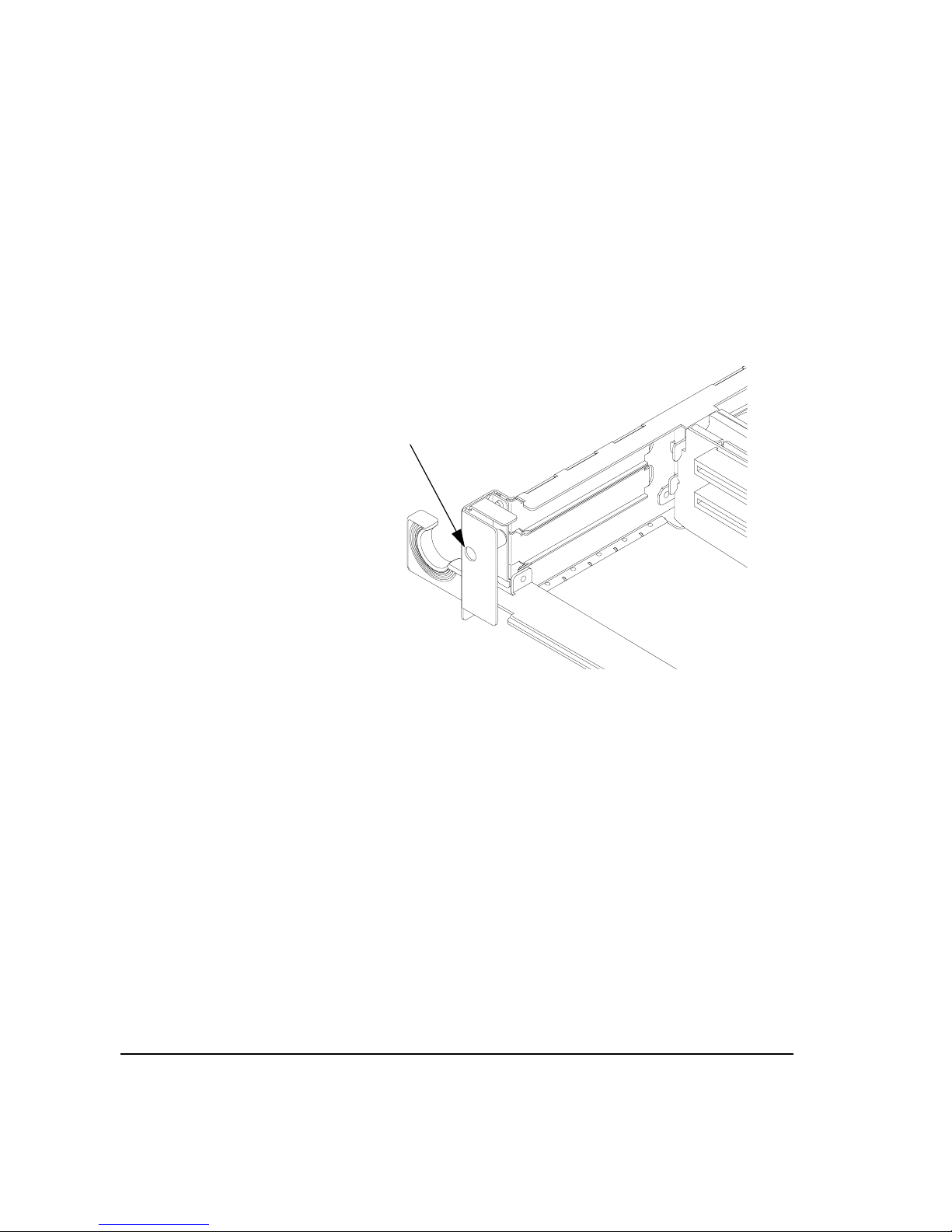
Loosen the card retainer captive screw (see Figure 2) for the appropriate
slot, and then remove the card retainer, as shown in Figure 3.
Card Retainer Captive Screw
Figure 2 Card Retainer Captive Screw
6
Page 7

Card Retainer
Slot Cover Plate
Procedure
Figure 3 Removing the Card Retainer and Slot Cover Plate
6 Remove the slot cover plate by pulling it out of the PCI module, as shown
in Figure 3.
7 Refer to your PCI card installation manual, and set any configuration
switches or jumpers that may be required for your application.
7
Page 8

Procedure
8 Install the PCI card in the slot, as shown in Figure 4. Make sure its con-
nector is completely seated in the PCI backplane.
PCI Option Card
Figure 4 Installing a PCI Option Card
9 Replace the PCI card retainer, and then tighten its screw.
8
Page 9
Procedure
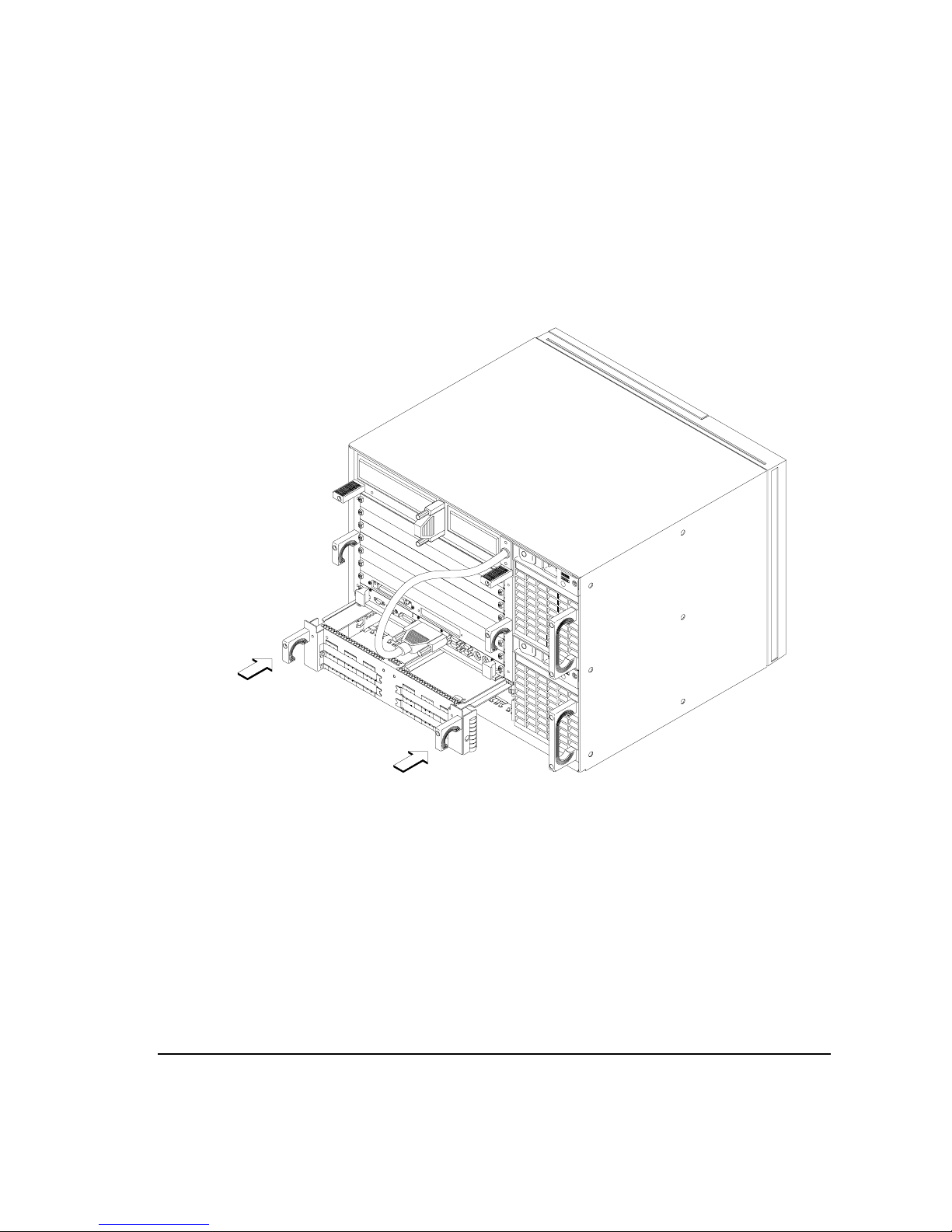
10 Slide the PCI module into the VMEbus chassis, as shown in Figure 5, and
tighten its handle screws.
Figure 5 Installing the PCI Module into the VMEbus Chassis
9
Page 10

Procedure
)
11 If your system has a Model 743 VMEbus board computer installed, you may need
to update its firmware to make use of the PCI module. (Model 744 board computers do not require a firmware upgrade.)
A new Boot ROM is shipped with the PCI Module upgrade kit. To determine if the Boot ROM in your system needs to be replaced, you need to
determine the revision number, which can be done in two ways: use the
Boot Console Handler (BCH) interface as described in the Model 743
Owner’s Guide, or you can examine the label on the Boot ROM - a revision number is printed on the label. If the revision number on the Boot
ROM installed on the Model 743 is a lower number than the one included
in this kit, you should replace that Boot ROM with the one in this kit. If
the revision number on the Boot ROOM installed on the Model 743 is
equal to or greater than the one included in this kit, DO NOT replace the
Boot ROM on the model 743.
a Loosen the board computer’s four captive screws.
b Push the ejector handles to the outside of the board and remove the board
computer from the Model 748 card cage.
c Remove any option cards, if installed. Refer to theModel 743 Owner’s Guide
for specific instructions for you option card.
NOTE: Before removing the Boot ROM, note its orientation. The replacement Boot
ROM must be installed in the same orientation.
d Remove the Boot ROM from its socket using the IC removal tool.
e Align the new Boot ROM in its socket and carefully press it into the socket.
Boot ROM (U54
Figure 6 Model 743 Boot ROM Location
10
Page 11

Procedure
12 Plug in the power cord(s), and then turn on the power for the VMEbus
chassis and boot the operating system.
13 Log in as root and use theSAM utility to configure the HP-UX kernel for
PCI support.
14 When SAM has started, choose the Kernel Configuration ->
menu.
15 From the Kernel Configuration menu, choose Drivers
16 From the Drivers menu, select GSCtoPCI Driver.
17 Go to the Actions menu and select Create a New Kernel.
18 When the new kernel is built, SAM asks if you want to move the kernel
into place and reboot. Choose Yes.
The system reboots with the PCI driver loaded.
For More Information
Refer to Installing Peripherals and your PCI card’s installation guide for
information on the PCI accessory card application, loading the software, and
running it.
11
Page 12

Procedure
12
 Loading...