

Page 1

hp LaserJet 9000mfp series printer
service ____________________
This manual is used in conjunction with the HP LaserJet 9000 series
printer service manual.
Page 2

© Copyright Hewlett-Packard
Company, 2002
All Rights Reserved.
Reproduction, adaptation, or
translation without prior written
permission is prohibited, except
as allowed under the copyright
laws.
Part number: C8523-90921
First Edition, March 2002
Warranty
The information contained in this
document is subject to change
without notice.
Hewlett-Packard makes no
warranty of any kind with respect
to this information. HEWLETTPACKARD SPECIFICALLY
DISCLAIMS THE IMPLIED
WARRANTY OF
MERCHANTABILITY AND
FITNESS FOR A PARTICULAR
PURPOSE.
Hewlett-Packard shall not be
liable for any direct, indirect,
incidental, consequential, or
other damage alleged in
connection with the furnishing or
use of this information.
Trademark Credits
Adobe® and PostScript® are
trademarks of Adobe Systems
Incorporated.
Microsoft
Windows
trademarks of Microsoft
Corporation.
TrueType
of Apple Computer, Inc.
UNIX® is a registered trademark
of The Open Group.
®
, MS-DOS®, and
®
are U.S. registered
TM
is a U.S. trademark
Hewlett-Packard Company
11311 Chinden Boulevard
Boise, Idaho 83714 U.S.A.
Page 3

Contents
List of tables
List of figures
1 Product information
Product features . . . . . . . . . . . . . . . . . . . . . . . . . . . . . . . . . . . . . . . 16
Product specifications . . . . . . . . . . . . . . . . . . . . . . . . . . . . . . . . . . . 17
Identification . . . . . . . . . . . . . . . . . . . . . . . . . . . . . . . . . . . . . . . 17
Specifications . . . . . . . . . . . . . . . . . . . . . . . . . . . . . . . . . . . . . . 17
Product overview. . . . . . . . . . . . . . . . . . . . . . . . . . . . . . . . . . . . . . . 19
Assembly identification . . . . . . . . . . . . . . . . . . . . . . . . . . . . . . . 19
External assembly locations . . . . . . . . . . . . . . . . . . . . . . . . . . . 20
Interface connections . . . . . . . . . . . . . . . . . . . . . . . . . . . . . . . . 21
Accessories. . . . . . . . . . . . . . . . . . . . . . . . . . . . . . . . . . . . . . . . 22
Regulatory information . . . . . . . . . . . . . . . . . . . . . . . . . . . . . . . . . . 23
Service approach . . . . . . . . . . . . . . . . . . . . . . . . . . . . . . . . . . . . . . 23
Parts and supplies . . . . . . . . . . . . . . . . . . . . . . . . . . . . . . . . . . 23
Warranty . . . . . . . . . . . . . . . . . . . . . . . . . . . . . . . . . . . . . . . . . . 23
Limited warranty for the print cartridge . . . . . . . . . . . . . . . . . . . 23
Service and support . . . . . . . . . . . . . . . . . . . . . . . . . . . . . . . . . 24
Worldwide service and support offices . . . . . . . . . . . . . . . . . . 25
2 Product requirements
Space requirements . . . . . . . . . . . . . . . . . . . . . . . . . . . . . . . . . . . . 28
Setup. . . . . . . . . . . . . . . . . . . . . . . . . . . . . . . . . . . . . . . . . . . . . . . . 30
Initial setup . . . . . . . . . . . . . . . . . . . . . . . . . . . . . . . . . . . . . . . . 30
Unpacking the MFP . . . . . . . . . . . . . . . . . . . . . . . . . . . . . . . . . 31
Removing the MFP from the shipping pallet. . . . . . . . . . . . . . . 32
Initial hardware setup . . . . . . . . . . . . . . . . . . . . . . . . . . . . . . . . 33
Installing the finishing device . . . . . . . . . . . . . . . . . . . . . . . . . . 35
Testing MFP printing and copying functions. . . . . . . . . . . . . . . 36
3 Product configuration
Control panel. . . . . . . . . . . . . . . . . . . . . . . . . . . . . . . . . . . . . . . . . . 38
Control panel layout . . . . . . . . . . . . . . . . . . . . . . . . . . . . . . . . 38
Touch-screen graphical display layout . . . . . . . . . . . . . . . . . . . 39
Settings and defaults. . . . . . . . . . . . . . . . . . . . . . . . . . . . . . . . . . . . 41
Setting the display language. . . . . . . . . . . . . . . . . . . . . . . . . . . 41
Setting tray registration . . . . . . . . . . . . . . . . . . . . . . . . . . . . . . 41
Print driver information . . . . . . . . . . . . . . . . . . . . . . . . . . . . . . . 43
Factory default settings . . . . . . . . . . . . . . . . . . . . . . . . . . . . . . 43
Control panel menus . . . . . . . . . . . . . . . . . . . . . . . . . . . . . . . . . . . . 46
Menu map. . . . . . . . . . . . . . . . . . . . . . . . . . . . . . . . . . . . . . . . . 46
Using a menu map . . . . . . . . . . . . . . . . . . . . . . . . . . . . . . . . . . 46
Retrieve job menu . . . . . . . . . . . . . . . . . . . . . . . . . . . . . . . . . . 47
Information menu . . . . . . . . . . . . . . . . . . . . . . . . . . . . . . . . . . . 47
Paper handling menu . . . . . . . . . . . . . . . . . . . . . . . . . . . . . . . . 47
Configure device menu. . . . . . . . . . . . . . . . . . . . . . . . . . . . . . . 49
Diagnostics menu . . . . . . . . . . . . . . . . . . . . . . . . . . . . . . . . . . . 51
Contents 3
Page 4

Service menu . . . . . . . . . . . . . . . . . . . . . . . . . . . . . . . . . . . . . . .51
Remote firmware upgrade . . . . . . . . . . . . . . . . . . . . . . . . . . . . . . . .52
Downloading the new firmware to the MFP . . . . . . . . . . . . . . . .52
Using HP Web JetAdmin . . . . . . . . . . . . . . . . . . . . . . . . . . . . . .53
4 Product maintenance
Cleaning the MFP and accessories . . . . . . . . . . . . . . . . . . . . . . . . .56
General cleaning . . . . . . . . . . . . . . . . . . . . . . . . . . . . . . . . . . . .56
ADF cleaning . . . . . . . . . . . . . . . . . . . . . . . . . . . . . . . . . . . . . . .57
Glass cleaning . . . . . . . . . . . . . . . . . . . . . . . . . . . . . . . . . . . . . .63
5 Theory of operation
Differences in print engines . . . . . . . . . . . . . . . . . . . . . . . . . . . . . . .66
Mechanical structure . . . . . . . . . . . . . . . . . . . . . . . . . . . . . . . . . . . .68
Motors and fans . . . . . . . . . . . . . . . . . . . . . . . . . . . . . . . . . . . . . . . .70
Basic block diagram . . . . . . . . . . . . . . . . . . . . . . . . . . . . . . . . . . . . .72
Basic system configuration. . . . . . . . . . . . . . . . . . . . . . . . . . . . . . . .73
Scanner unit systems. . . . . . . . . . . . . . . . . . . . . . . . . . . . . . . . .73
Scan mode. . . . . . . . . . . . . . . . . . . . . . . . . . . . . . . . . . . . . . . . .73
Power supply assembly . . . . . . . . . . . . . . . . . . . . . . . . . . . . . . .75
Low-voltage power supply circuit . . . . . . . . . . . . . . . . . . . . . . .78
Scanner controller circuit . . . . . . . . . . . . . . . . . . . . . . . . . . . . . .80
Flatbed operation . . . . . . . . . . . . . . . . . . . . . . . . . . . . . . . . . . . . . . .81
Flatbed document exposure control . . . . . . . . . . . . . . . . . . . . .81
Flatbed optical drive control . . . . . . . . . . . . . . . . . . . . . . . . . . .82
Flatbed optical unit operation. . . . . . . . . . . . . . . . . . . . . . . . . . .83
Flatbed document size detection . . . . . . . . . . . . . . . . . . . . . . . .84
ADF operation . . . . . . . . . . . . . . . . . . . . . . . . . . . . . . . . . . . . . . . . .87
ADF document exposure control . . . . . . . . . . . . . . . . . . . . . . . .87
ADF document feed control . . . . . . . . . . . . . . . . . . . . . . . . . . . .88
ADF document size detection . . . . . . . . . . . . . . . . . . . . . . . . . .90
ADF feeder sensors . . . . . . . . . . . . . . . . . . . . . . . . . . . . . . . . . .91
ADF document skew detection . . . . . . . . . . . . . . . . . . . . . . . . .92
Scanned data flow . . . . . . . . . . . . . . . . . . . . . . . . . . . . . . . . . . . . . .93
Copy processor board . . . . . . . . . . . . . . . . . . . . . . . . . . . . . . . . . . .94
CPB terminology . . . . . . . . . . . . . . . . . . . . . . . . . . . . . . . . . . . .94
Scanning process control signals. . . . . . . . . . . . . . . . . . . . . . . .95
Typical scanning process flow . . . . . . . . . . . . . . . . . . . . . . . . . .95
Copy processor board LEDs . . . . . . . . . . . . . . . . . . . . . . . . . . .96
6 Removal and replacement
Introduction. . . . . . . . . . . . . . . . . . . . . . . . . . . . . . . . . . . . . . . . . . .101
Removal and replacement strategy . . . . . . . . . . . . . . . . . . . .101
Electrostatic discharge. . . . . . . . . . . . . . . . . . . . . . . . . . . . . . .101
Required tools . . . . . . . . . . . . . . . . . . . . . . . . . . . . . . . . . . . . .101
External covers. . . . . . . . . . . . . . . . . . . . . . . . . . . . . . . . . . . . . . . .102
Control panel . . . . . . . . . . . . . . . . . . . . . . . . . . . . . . . . . . . . . .102
ADF feeder cover . . . . . . . . . . . . . . . . . . . . . . . . . . . . . . . . . .104
ADF feeder cover handle . . . . . . . . . . . . . . . . . . . . . . . . . . . .106
ADF back cover . . . . . . . . . . . . . . . . . . . . . . . . . . . . . . . . . . . .107
ADF front cover . . . . . . . . . . . . . . . . . . . . . . . . . . . . . . . . . . . .108
Lower delivery roller cover . . . . . . . . . . . . . . . . . . . . . . . . . . . .109
White board cover . . . . . . . . . . . . . . . . . . . . . . . . . . . . . . . . . .110
Copy processor board . . . . . . . . . . . . . . . . . . . . . . . . . . . . . . .111
Flatbed rail cover . . . . . . . . . . . . . . . . . . . . . . . . . . . . . . . . . . .112
Flatbed back cover. . . . . . . . . . . . . . . . . . . . . . . . . . . . . . . . . .113
Flatbed right cover . . . . . . . . . . . . . . . . . . . . . . . . . . . . . . . . . .114
4 C8523-90921
Page 5

Flatbed left cover . . . . . . . . . . . . . . . . . . . . . . . . . . . . . . . . . . 115
Flatbed upper front cover . . . . . . . . . . . . . . . . . . . . . . . . . . . . 116
Flatbed lower front cover . . . . . . . . . . . . . . . . . . . . . . . . . . . . 117
ADF base cover assembly . . . . . . . . . . . . . . . . . . . . . . . . . . . 118
Glass. . . . . . . . . . . . . . . . . . . . . . . . . . . . . . . . . . . . . . . . . . . . 123
Internal . . . . . . . . . . . . . . . . . . . . . . . . . . . . . . . . . . . . . . . . . . . . . 125
ADF optical unit. . . . . . . . . . . . . . . . . . . . . . . . . . . . . . . . . . . . 125
ADF scanning lamp . . . . . . . . . . . . . . . . . . . . . . . . . . . . . . . . 130
ADF shading filter . . . . . . . . . . . . . . . . . . . . . . . . . . . . . . . . . . 133
Flatbed optical unit . . . . . . . . . . . . . . . . . . . . . . . . . . . . . . . . . 134
Flatbed scanning lamp . . . . . . . . . . . . . . . . . . . . . . . . . . . . . . 137
Flatbed shading filter. . . . . . . . . . . . . . . . . . . . . . . . . . . . . . . . 139
Switch and solenoids. . . . . . . . . . . . . . . . . . . . . . . . . . . . . . . . . . . 141
ADF feeder cover detection switch . . . . . . . . . . . . . . . . . . . . . 141
Weight solenoid . . . . . . . . . . . . . . . . . . . . . . . . . . . . . . . . . . . 142
Shutter solenoid . . . . . . . . . . . . . . . . . . . . . . . . . . . . . . . . . . . 143
Motors and fans. . . . . . . . . . . . . . . . . . . . . . . . . . . . . . . . . . . . . . . 144
Pickup motor. . . . . . . . . . . . . . . . . . . . . . . . . . . . . . . . . . . . . . 144
Delivery motor. . . . . . . . . . . . . . . . . . . . . . . . . . . . . . . . . . . . . 146
Flatbed motor . . . . . . . . . . . . . . . . . . . . . . . . . . . . . . . . . . . . . 148
Power supply assembly . . . . . . . . . . . . . . . . . . . . . . . . . . . . . 150
ADF fan assembly. . . . . . . . . . . . . . . . . . . . . . . . . . . . . . . . . . 153
Flatbed fan assembly . . . . . . . . . . . . . . . . . . . . . . . . . . . . . . . 154
PCB assemblies . . . . . . . . . . . . . . . . . . . . . . . . . . . . . . . . . . . . . . 155
ADF analog processor PCB . . . . . . . . . . . . . . . . . . . . . . . . . . 155
ADF inverter PCB . . . . . . . . . . . . . . . . . . . . . . . . . . . . . . . . . . 156
ADF intermediate PCB . . . . . . . . . . . . . . . . . . . . . . . . . . . . . . 157
ADF width detection sensor assembly . . . . . . . . . . . . . . . . . . 158
Flatbed inverter PCB. . . . . . . . . . . . . . . . . . . . . . . . . . . . . . . . 159
Flatbed intermediate PCB. . . . . . . . . . . . . . . . . . . . . . . . . . . . 160
Scanner controller board. . . . . . . . . . . . . . . . . . . . . . . . . . . . . 162
Intermediate PCB assembly . . . . . . . . . . . . . . . . . . . . . . . . . . 164
Power supply assembly . . . . . . . . . . . . . . . . . . . . . . . . . . . . . 165
Rollers and belts . . . . . . . . . . . . . . . . . . . . . . . . . . . . . . . . . . . . . . 168
Pickup roller (D-roller). . . . . . . . . . . . . . . . . . . . . . . . . . . . . . . 168
Pickup roller assembly . . . . . . . . . . . . . . . . . . . . . . . . . . . . . . 169
Feed roller assembly. . . . . . . . . . . . . . . . . . . . . . . . . . . . . . . . 170
Lower registration roller assembly . . . . . . . . . . . . . . . . . . . . . 171
Lower delivery roller . . . . . . . . . . . . . . . . . . . . . . . . . . . . . . . . 177
Upper delivery roller assembly . . . . . . . . . . . . . . . . . . . . . . . . 179
Separation belt assembly . . . . . . . . . . . . . . . . . . . . . . . . . . . . 180
Separation belts . . . . . . . . . . . . . . . . . . . . . . . . . . . . . . . . . . . 183
Scan engine . . . . . . . . . . . . . . . . . . . . . . . . . . . . . . . . . . . . . . 185
7 Troubleshooting
Troubleshooting process . . . . . . . . . . . . . . . . . . . . . . . . . . . . . . . 190
Preliminary operating checks . . . . . . . . . . . . . . . . . . . . . . . . 191
Power on . . . . . . . . . . . . . . . . . . . . . . . . . . . . . . . . . . . . . . . . . . . . 192
Power-on defects . . . . . . . . . . . . . . . . . . . . . . . . . . . . . . . . . . 192
Malfunction troubleshooting . . . . . . . . . . . . . . . . . . . . . . . . . . 193
Troubleshooting with control panel messages . . . . . . . . . . . . . . . 194
Control panel display . . . . . . . . . . . . . . . . . . . . . . . . . . . . . . . 194
Event log page . . . . . . . . . . . . . . . . . . . . . . . . . . . . . . . . . . . . 194
Control panel messages . . . . . . . . . . . . . . . . . . . . . . . . . . . . . . . . 197
MFP message tables . . . . . . . . . . . . . . . . . . . . . . . . . . . . . . . 198
Alphabetic error messages . . . . . . . . . . . . . . . . . . . . . . . . . . 198
Numeric error messages . . . . . . . . . . . . . . . . . . . . . . . . . . . . 200
Troubleshooting with the copy processor board . . . . . . . . . . . . . . 203
C8523-90921 5
Page 6

User- and service-level diagnostics . . . . . . . . . . . . . . . . . . . . . . . .205
Diagnostics. . . . . . . . . . . . . . . . . . . . . . . . . . . . . . . . . . . . . . . .205
ADF paper-path test . . . . . . . . . . . . . . . . . . . . . . . . . . . . . . . .205
Service test . . . . . . . . . . . . . . . . . . . . . . . . . . . . . . . . . . . . . . .206
Service-level diagnostics . . . . . . . . . . . . . . . . . . . . . . . . . . . . . . . .207
Service menu . . . . . . . . . . . . . . . . . . . . . . . . . . . . . . . . . . . . .207
ADF and glass calibrations. . . . . . . . . . . . . . . . . . . . . . . . . . . . . . .209
ADF calibrations. . . . . . . . . . . . . . . . . . . . . . . . . . . . . . . . . . . .209
Glass calibrations. . . . . . . . . . . . . . . . . . . . . . . . . . . . . . . . . . .217
Jam troubleshooting . . . . . . . . . . . . . . . . . . . . . . . . . . . . . . . . . . .220
Jams. . . . . . . . . . . . . . . . . . . . . . . . . . . . . . . . . . . . . . . . . . . . .220
Evaluating the information pages . . . . . . . . . . . . . . . . . . . . . . . . . .222
Configuration page . . . . . . . . . . . . . . . . . . . . . . . . . . . . . . . . .222
Jetdirect page . . . . . . . . . . . . . . . . . . . . . . . . . . . . . . . . . . . . .224
Supplies status page . . . . . . . . . . . . . . . . . . . . . . . . . . . . . . . .225
Usage page . . . . . . . . . . . . . . . . . . . . . . . . . . . . . . . . . . . . . .226
File directory page . . . . . . . . . . . . . . . . . . . . . . . . . . . . . . . . . .227
Image-formation troubleshooting . . . . . . . . . . . . . . . . . . . . . . . . . .228
Image defects. . . . . . . . . . . . . . . . . . . . . . . . . . . . . . . . . . . . . .229
Measurement and adjustment . . . . . . . . . . . . . . . . . . . . . . . . . . . .232
ADF unit height adjustment . . . . . . . . . . . . . . . . . . . . . . . . . . .232
ADF skew adjustment . . . . . . . . . . . . . . . . . . . . . . . . . . . . . . .234
ADF width sensor volume adjustment . . . . . . . . . . . . . . . . . . .236
Weight solenoid stroke adjustment . . . . . . . . . . . . . . . . . . . . .237
Scanner controller PCB . . . . . . . . . . . . . . . . . . . . . . . . . . . . . .238
Connector locations . . . . . . . . . . . . . . . . . . . . . . . . . . . . . . . . . . . .239
Electrical structure . . . . . . . . . . . . . . . . . . . . . . . . . . . . . . . . . . . . .240
Wiring diagrams . . . . . . . . . . . . . . . . . . . . . . . . . . . . . . . . . . . . . . .241
8 Parts and diagrams
Introduction. . . . . . . . . . . . . . . . . . . . . . . . . . . . . . . . . . . . . . . . . . .244
Ordering parts . . . . . . . . . . . . . . . . . . . . . . . . . . . . . . . . . . . . .244
Consumables, supplies, accessories,
FRUs, and documentation . . . . . . . . . . . . . . . . . . . . . . . . . . . .245
Common hardware. . . . . . . . . . . . . . . . . . . . . . . . . . . . . . . . . .247
Illustrations and parts lists . . . . . . . . . . . . . . . . . . . . . . . . . . . . . . .248
MFP system assembly. . . . . . . . . . . . . . . . . . . . . . . . . . . . . . .249
Image scanner . . . . . . . . . . . . . . . . . . . . . . . . . . . . . . . . . . . . .251
External panels and covers . . . . . . . . . . . . . . . . . . . . . . . . . . .253
Flatbed scanner assembly . . . . . . . . . . . . . . . . . . . . . . . . . . . .255
Flatbed optical assembly . . . . . . . . . . . . . . . . . . . . . . . . . . . . .259
ADF scanner assembly . . . . . . . . . . . . . . . . . . . . . . . . . . . . . .260
Paper pickup assembly . . . . . . . . . . . . . . . . . . . . . . . . . . . . . .262
ADF main assembly. . . . . . . . . . . . . . . . . . . . . . . . . . . . . . . . .266
ADF optical assembly . . . . . . . . . . . . . . . . . . . . . . . . . . . . . . .268
PCB assemblies. . . . . . . . . . . . . . . . . . . . . . . . . . . . . . . . . . . .269
Alphabetical parts list . . . . . . . . . . . . . . . . . . . . . . . . . . . . . . . . . . .270
Numerical parts list. . . . . . . . . . . . . . . . . . . . . . . . . . . . . . . . . . . . .274
Index
6 C8523-90921
Page 7

List of tables
Table 1. Features of the HP LaserJet 9000mfp . . . . . . . . . . . . . . . 16
Table 2. Physical specifications . . . . . . . . . . . . . . . . . . . . . . . . . . 17
Table 3. Electrical specifications . . . . . . . . . . . . . . . . . . . . . . . . . . 18
Table 4. Environmental specifications . . . . . . . . . . . . . . . . . . . . 18
Table 5. Noise level specifications . . . . . . . . . . . . . . . . . . . . . . . . 18
Table 6. Control panel features, and key functions . . . . . . . . . . . . 39
Table 7. Touch-screen graphical display features and functions . . 40
Table 8. Factory default settings . . . . . . . . . . . . . . . . . . . . . . . . . . 43
Table 9. Retrieve job menu . . . . . . . . . . . . . . . . . . . . . . . . . . . . . . 47
Table 10. Information menu . . . . . . . . . . . . . . . . . . . . . . . . . . . . . . 47
Table 11. Paper handling menu default settings . . . . . . . . . . . . . . 47
Table 12. Configure device menu . . . . . . . . . . . . . . . . . . . . . . . . . 49
Table 13. Diagnostics menu . . . . . . . . . . . . . . . . . . . . . . . . . . . . . . 51
Table 14. Service menu . . . . . . . . . . . . . . . . . . . . . . . . . . . . . . . . . 51
Table 15. Differences between the HP LaserJet 9000 series
and the HP LaserJet 9000mfp . . . . . . . . . . . . . . . . . . . . . . . . . . . . 67
Table 16. Mechanical structure . . . . . . . . . . . . . . . . . . . . . . . . . . . 68
Table 17. Mechanical structure . . . . . . . . . . . . . . . . . . . . . . . . . . . 69
Table 18. Motors and fans . . . . . . . . . . . . . . . . . . . . . . . . . . . . . . . 71
Table 19. Electrical specifications for the MFP . . . . . . . . . . . . . . . 75
Table 20. Copy processor board LEDs . . . . . . . . . . . . . . . . . . . . . 96
Table 21. Primary steps for troubleshooting . . . . . . . . . . . . . . . . . 190
Table 22. Power-on defects or blank display . . . . . . . . . . . . . . . . 192
Table 23. Malfunction troubleshooting . . . . . . . . . . . . . . . . . . . . . 193
Table 24. Alphabetic error messages . . . . . . . . . . . . . . . . . . . . . . 198
Table 25. Numeric error messages . . . . . . . . . . . . . . . . . . . . . . . 200
Table 26. Troubleshooting copy processor bo ard LEDs . . . . . . . 204
Table 27. Replaced components and required calibrations . . . . . 208
Table 28. General jam troubleshooting . . . . . . . . . . . . . . . . . . . . 220
Table 29. General jam troubleshooting . . . . . . . . . . . . . . . . . . . . 221
Table 30. Image quality checks . . . . . . . . . . . . . . . . . . . . . . . . . . 228
Table 31. Image defects . . . . . . . . . . . . . . . . . . . . . . . . . . . . . . . . 229
Table 32. Sensors . . . . . . . . . . . . . . . . . . . . . . . . . . . . . . . . . . . . 240
Table 33. Consumables, supplies, accessor ies ,
FRUs, and documentation . . . . . . . . . . . . . . . . . . . . . . . . . . . . . . 245
Table 34. Hardware table . . . . . . . . . . . . . . . . . . . . . . . . . . . . . . . 247
Table 35. Common torque values . . . . . . . . . . . . . . . . . . . . . . . . 247
Table 36. MFP system assembly . . . . . . . . . . . . . . . . . . . . . . . . . 249
Table 37. Image scanner . . . . . . . . . . . . . . . . . . . . . . . . . . . . . . . 251
Table 38. Image scanner . . . . . . . . . . . . . . . . . . . . . . . . . . . . . . . 252
Table 39. External panels and covers (1 of 2) . . . . . . . . . . . . . . . 253
Table 40. External panels and covers (2 of 2) . . . . . . . . . . . . . . . 254
Table 41. Flatbed scanner assembly (1 of 3) . . . . . . . . . . . . . . . . 255
Table 42. Flatbed scanner assembly (2 of 3) . . . . . . . . . . . . . . . . 256
Table 43. Flatbed scanner assembly (3 of 3) . . . . . . . . . . . . . . . . 258
Table 44. Flatbed optical assembly . . . . . . . . . . . . . . . . . . . . . . . 259
Table 45. ADF scanner assembly . . . . . . . . . . . . . . . . . . . . . . . . 261
Table 46. Paper pickup assembly (1 of 2) . . . . . . . . . . . . . . . . . . 263
Table 47. Paper pickup assembly (2 of 2) . . . . . . . . . . . . . . . . . . 265
C8523-90921 7
Page 8

Table 48. ADF main assembly . . . . . . . . . . . . . . . . . . . . . . . . . . .267
Table 49. ADF optical assembly . . . . . . . . . . . . . . . . . . . . . . . . . .268
Table 50. PCB assemblies . . . . . . . . . . . . . . . . . . . . . . . . . . . . . .269
Table 51. Alphabetical parts list . . . . . . . . . . . . . . . . . . . . . . . . . . .270
Table 52. Numerical parts list . . . . . . . . . . . . . . . . . . . . . . . . . . . .274
8 List of tables C8523-90921
Page 9

List of figures
Figure 1. Sample identification label . . . . . . . . . . . . . . . . . . . . . . . . 17
Figure 2. Assembly identification. . . . . . . . . . . . . . . . . . . . . . . . . . . 19
Figure 3. External assembly locations (front view) . . . . . . . . . . . . . 20
Figure 4. External assembly locations (back view) . . . . . . . . . . . . . 20
Figure 5. Interface connections . . . . . . . . . . . . . . . . . . . . . . . . . . . 21
Figure 6. Accessories . . . . . . . . . . . . . . . . . . . . . . . . . . . . . . . . . . . 22
Figure 7. MFP space requirements with a finishing device
(3,000-sheet stapler/stacker shown) (top view) . . . . . . . . . . . . 28
Figure 8. MFP space requirements with a finishing device
(3,000-sheet stapler/stacker shown) (front view) . . . . . . . . . . . 29
Figure 9. Unpacking the MFP . . . . . . . . . . . . . . . . . . . . . . . . . . . . . 31
Figure 10. Removing the MFP from the shipping pa llet (1 of 2) . . . 32
Figure 11. Removing the MFP from the shipping pa llet (2 of 2) . . . 32
Figure 12. Initial hardware setup (1 of 4). . . . . . . . . . . . . . . . . . . . . 33
Figure 13. Initial hardware setup (2 of 4). . . . . . . . . . . . . . . . . . . . . 33
Figure 14. Initial hardware setup (3 of 4). . . . . . . . . . . . . . . . . . . . . 34
Figure 15. Initial hardware setup (4 of 4). . . . . . . . . . . . . . . . . . . . . 34
Figure 16. Installing the finishing device (1 of 2). . . . . . . . . . . . . . . 35
Figure 17. Installing the finishing device (2 of 2). . . . . . . . . . . . . . . 36
Figure 18. Control panel layout . . . . . . . . . . . . . . . . . . . . . . . . . . . . 38
Figure 19. Touch-screen graphical display layout. . . . . . . . . . . . . . 39
Figure 20. Registration page (1 of 2). . . . . . . . . . . . . . . . . . . . . . . . 42
Figure 21. Registration page (2 of 2). . . . . . . . . . . . . . . . . . . . . . . . 42
Figure 22. ADF delivery system (1 of 5) . . . . . . . . . . . . . . . . . . . . . 57
Figure 23. ADF delivery system (2 of 5) . . . . . . . . . . . . . . . . . . . . . 57
Figure 24. ADF delivery system (3 of 5) . . . . . . . . . . . . . . . . . . . . . 58
Figure 25. ADF delivery system (4 of 5) . . . . . . . . . . . . . . . . . . . . . 58
Figure 26. ADF delivery system (5 of 5) . . . . . . . . . . . . . . . . . . . . . 58
Figure 27. Upper ADF glass strip (1 of 4) . . . . . . . . . . . . . . . . . . . . 59
Figure 28. Upper ADF glass strip (2 of 4) . . . . . . . . . . . . . . . . . . . . 59
Figure 29. Upper ADF glass strip (3 of 4) . . . . . . . . . . . . . . . . . . . . 60
Figure 30. Upper ADF glass strip (4 of 4) . . . . . . . . . . . . . . . . . . . . 60
Figure 31. ADF rollers (1 of 6). . . . . . . . . . . . . . . . . . . . . . . . . . . . . 61
Figure 32. ADF rollers (2 of 6). . . . . . . . . . . . . . . . . . . . . . . . . . . . . 61
Figure 33. ADF rollers (3 of 6). . . . . . . . . . . . . . . . . . . . . . . . . . . . . 61
Figure 34. ADF rollers (4 of 6). . . . . . . . . . . . . . . . . . . . . . . . . . . . . 62
Figure 35. ADF rollers (5 of 6). . . . . . . . . . . . . . . . . . . . . . . . . . . . . 62
Figure 36. ADF rollers (6 of 6). . . . . . . . . . . . . . . . . . . . . . . . . . . . . 62
Figure 37. Differences in print engine . . . . . . . . . . . . . . . . . . . . . . . 66
Figure 38. Mechanical structure (1 of 2) . . . . . . . . . . . . . . . . . . . . . 68
Figure 39. Mechanical structure (2 of 2) . . . . . . . . . . . . . . . . . . . . . 69
Figure 40. Motors and fans . . . . . . . . . . . . . . . . . . . . . . . . . . . . . . . 70
Figure 41. Basic block diagram. . . . . . . . . . . . . . . . . . . . . . . . . . . . 72
Figure 42. Basic system configuration . . . . . . . . . . . . . . . . . . . . . . 74
Figure 43. Power supply assembly . . . . . . . . . . . . . . . . . . . . . . . . . 76
Figure 44. PowerSave flowchart . . . . . . . . . . . . . . . . . . . . . . . . . . . 77
Figure 45. Low-voltage power supply circuit . . . . . . . . . . . . . . . . . . 78
Figure 46. Printer power supply . . . . . . . . . . . . . . . . . . . . . . . . . . . 79
Figure 47. Scanner controller circuit . . . . . . . . . . . . . . . . . . . . . . . . 80
C8523-90921 9
Page 10

Figure 48. Flatbed document exposure control . . . . . . . . . . . . . . . .81
Figure 49. Flatbed optical drive control . . . . . . . . . . . . . . . . . . . . . .82
Figure 50. Flatbed optical unit operation . . . . . . . . . . . . . . . . . . . . .83
Figure 51. Flatbed document size detection. . . . . . . . . . . . . . . . . . .84
Figure 52. Functions operation. . . . . . . . . . . . . . . . . . . . . . . . . . . . .85
Figure 53. ADF angle detection . . . . . . . . . . . . . . . . . . . . . . . . . . . .86
Figure 54. ADF document exposure control. . . . . . . . . . . . . . . . . . .87
Figure 55. ADF document feed control. . . . . . . . . . . . . . . . . . . . . . .88
Figure 56. ADF document size detection . . . . . . . . . . . . . . . . . . . . .90
Figure 57. ADF feeder sensors . . . . . . . . . . . . . . . . . . . . . . . . . . . .91
Figure 58. Document skew jam . . . . . . . . . . . . . . . . . . . . . . . . . . . .92
Figure 59. Scanned data flow. . . . . . . . . . . . . . . . . . . . . . . . . . . . . .93
Figure 60. Copy processor board. . . . . . . . . . . . . . . . . . . . . . . . . . .94
Figure 61. Copy processor board LEDs . . . . . . . . . . . . . . . . . . . . . .96
Figure 62. Control panel (1 of 3). . . . . . . . . . . . . . . . . . . . . . . . . . .102
Figure 63. Control panel (2 of 3). . . . . . . . . . . . . . . . . . . . . . . . . . .102
Figure 64. Control panel (3 of 3). . . . . . . . . . . . . . . . . . . . . . . . . . .103
Figure 65. ADF feeder cover (1 of 3) . . . . . . . . . . . . . . . . . . . . . . .104
Figure 66. ADF feeder cover (2 of 3) . . . . . . . . . . . . . . . . . . . . . . .104
Figure 67. ADF feeder cover (3 of 3) . . . . . . . . . . . . . . . . . . . . . . .105
Figure 68. ADF feeder cover handle (1 of 2) . . . . . . . . . . . . . . . . .106
Figure 69. ADF feeder cover handle (2 of 2) . . . . . . . . . . . . . . . . .106
Figure 70. ADF back cover (1 of 2) . . . . . . . . . . . . . . . . . . . . . . . .107
Figure 71. ADF back cover (2 of 2) . . . . . . . . . . . . . . . . . . . . . . . .107
Figure 72. ADF front cover . . . . . . . . . . . . . . . . . . . . . . . . . . . . . . .108
Figure 73. Delivery roller cover. . . . . . . . . . . . . . . . . . . . . . . . . . . .109
Figure 74. White board cover . . . . . . . . . . . . . . . . . . . . . . . . . . . . .110
Figure 75. Copy processor board. . . . . . . . . . . . . . . . . . . . . . . . . .111
Figure 76. Flatbed rail cover. . . . . . . . . . . . . . . . . . . . . . . . . . . . . .112
Figure 77. Flatbed back cover (1 of 2) . . . . . . . . . . . . . . . . . . . . . .113
Figure 78. Flatbed back cover (2 of 2) . . . . . . . . . . . . . . . . . . . . . .113
Figure 79. Flatbed right cover (1 of 2) . . . . . . . . . . . . . . . . . . . . . .114
Figure 80. Flatbed right cover (2 of 2) . . . . . . . . . . . . . . . . . . . . . .114
Figure 81. Flatbed left cover (1 of 2) . . . . . . . . . . . . . . . . . . . . . . .115
Figure 82. Flatbed left cover (2 of 2) . . . . . . . . . . . . . . . . . . . . . . .115
Figure 83. Flatbed upper front cover . . . . . . . . . . . . . . . . . . . . . . .116
Figure 84. Flatbed lower front cover. . . . . . . . . . . . . . . . . . . . . . . .117
Figure 85. ADF base cover assembly (1 of 9) . . . . . . . . . . . . . . . .118
Figure 86. ADF base cover assembly (2 of 9) . . . . . . . . . . . . . . . .118
Figure 87. ADF base cover assembly (3 of 9) . . . . . . . . . . . . . . . .119
Figure 88. ADF base cover assembly (4 of 9) . . . . . . . . . . . . . . . .119
Figure 89. ADF base cover assembly (5 of 9) . . . . . . . . . . . . . . . .120
Figure 90. ADF base cover assembly (6 of 9) . . . . . . . . . . . . . . . .120
Figure 91. ADF base cover assembly (7 of 9) . . . . . . . . . . . . . . . .121
Figure 92. ADF base cover assembly (8 of 9) . . . . . . . . . . . . . . . .121
Figure 93. ADF base cover assembly (9 of 9) . . . . . . . . . . . . . . . .122
Figure 94. Glass (1 of 2). . . . . . . . . . . . . . . . . . . . . . . . . . . . . . . . .123
Figure 95. Glass (2 of 2). . . . . . . . . . . . . . . . . . . . . . . . . . . . . . . . .123
Figure 96. ADF optical unit (1 of 8). . . . . . . . . . . . . . . . . . . . . . . . .125
Figure 97. ADF optical unit (2 of 8). . . . . . . . . . . . . . . . . . . . . . . . .126
Figure 98. ADF optical unit (3 of 8). . . . . . . . . . . . . . . . . . . . . . . . .126
Figure 99. ADF optical unit (4 of 8). . . . . . . . . . . . . . . . . . . . . . . . .127
Figure 100. ADF optical unit (5 of 8). . . . . . . . . . . . . . . . . . . . . . . .127
Figure 101. ADF optical unit (6 of 8). . . . . . . . . . . . . . . . . . . . . . . .128
Figure 102. ADF optical unit (7 of 8). . . . . . . . . . . . . . . . . . . . . . . .128
Figure 103. ADF optical unit (8 of 8). . . . . . . . . . . . . . . . . . . . . . . .129
Figure 104. ADF scanning lamp (1 of 5). . . . . . . . . . . . . . . . . . . . .130
Figure 105. ADF scanning lamp (2 of 5). . . . . . . . . . . . . . . . . . . . .130
Figure 106. ADF scanning lamp (3 of 5). . . . . . . . . . . . . . . . . . . . .131
10 List of figures C8523-90921
Page 11

Figure 107. ADF scanning lamp (4 of 5) . . . . . . . . . . . . . . . . . . . . 131
Figure 108. ADF scanning lamp (5 of 5) . . . . . . . . . . . . . . . . . . . . 132
Figure 109. ADF shading filter (1 of 2) . . . . . . . . . . . . . . . . . . . . . 133
Figure 110. ADF shading filter (2 of 2) . . . . . . . . . . . . . . . . . . . . . 133
Figure 111. Flatbed optical unit (1 of 6). . . . . . . . . . . . . . . . . . . . . 134
Figure 112. Flatbed optical unit (2 of 6). . . . . . . . . . . . . . . . . . . . . 134
Figure 113. Flatbed optical unit (3 of 6). . . . . . . . . . . . . . . . . . . . . 135
Figure 114. Flatbed optical unit (4 of 6). . . . . . . . . . . . . . . . . . . . . 135
Figure 115. Flatbed optical unit (5 of 6). . . . . . . . . . . . . . . . . . . . . 136
Figure 116. Flatbed optical unit (6 of 6). . . . . . . . . . . . . . . . . . . . . 136
Figure 117. Flatbed scanning lamp (1 of 3). . . . . . . . . . . . . . . . . . 137
Figure 118. Flatbed scanning lamp (2 of 3). . . . . . . . . . . . . . . . . . 137
Figure 119. Flatbed scanning lamp (3 of 3). . . . . . . . . . . . . . . . . . 138
Figure 120. Flatbed shading filter (1 of 3) . . . . . . . . . . . . . . . . . . . 139
Figure 121. Flatbed shading filter (2 of 3) . . . . . . . . . . . . . . . . . . . 139
Figure 122. Flatbed shading filter (3 of 3) . . . . . . . . . . . . . . . . . . . 140
Figure 123. ADF feeder cover detection switch . . . . . . . . . . . . . . 141
Figure 124. Weight solenoid (1 of 2) . . . . . . . . . . . . . . . . . . . . . . . 142
Figure 125. Weight solenoid (2 of 2) . . . . . . . . . . . . . . . . . . . . . . . 142
Figure 126. Shutter solenoid . . . . . . . . . . . . . . . . . . . . . . . . . . . . . 143
Figure 127. Pickup motor (1 of 2) . . . . . . . . . . . . . . . . . . . . . . . . . 144
Figure 128. Pickup motor (2 of 2) . . . . . . . . . . . . . . . . . . . . . . . . . 144
Figure 129. Delivery motor (1 of 2) . . . . . . . . . . . . . . . . . . . . . . . . 146
Figure 130. Delivery motor (2 of 2) . . . . . . . . . . . . . . . . . . . . . . . . 146
Figure 131. Flatbed motor (1 of 3). . . . . . . . . . . . . . . . . . . . . . . . . 148
Figure 132. Flatbed motor (2 of 3). . . . . . . . . . . . . . . . . . . . . . . . . 148
Figure 133. Flatbed motor (3 of 3). . . . . . . . . . . . . . . . . . . . . . . . . 149
Figure 134. Power supply assembly (1 of 6). . . . . . . . . . . . . . . . . 150
Figure 135. Power supply assembly (2 of 6). . . . . . . . . . . . . . . . . 150
Figure 136. Power supply assembly (3 of 6). . . . . . . . . . . . . . . . . 151
Figure 137. Power supply assembly (4 of 6). . . . . . . . . . . . . . . . . 151
Figure 138. Power supply assembly (5 of 6). . . . . . . . . . . . . . . . . 152
Figure 139. Power supply assembly (6 of 6). . . . . . . . . . . . . . . . . 152
Figure 140. ADF fan . . . . . . . . . . . . . . . . . . . . . . . . . . . . . . . . . . . 153
Figure 141. Flatbed fan assembly. . . . . . . . . . . . . . . . . . . . . . . . . 154
Figure 142. ADF analog processor PCB. . . . . . . . . . . . . . . . . . . . 155
Figure 143. ADF inverter PCB (1 of 2) . . . . . . . . . . . . . . . . . . . . . 156
Figure 144. ADF inverter PCB (2 of 2) . . . . . . . . . . . . . . . . . . . . . 156
Figure 145. ADF intermediate PCB. . . . . . . . . . . . . . . . . . . . . . . . 157
Figure 146. ADF width detection sensor assembly. . . . . . . . . . . . 158
Figure 147. Flatbed inverter PCB (1 of 2) . . . . . . . . . . . . . . . . . . . 159
Figure 148. Flatbed intermediate PCB (1 of 2) . . . . . . . . . . . . . . . 160
Figure 149. Flatbed intermediate PCB (2 of 2) . . . . . . . . . . . . . . . 161
Figure 150. Scanner controller board (1 of 4) . . . . . . . . . . . . . . . . 162
Figure 151. Scanner controller board (2 of 4) . . . . . . . . . . . . . . . . 162
Figure 152. Scanner controller board (3 of 4) . . . . . . . . . . . . . . . . 163
Figure 153. Scanner controller board (4 of 4) . . . . . . . . . . . . . . . . 163
Figure 154. Intermediate PCB assembly. . . . . . . . . . . . . . . . . . . . 164
Figure 155. Power supply assembly (1 of 6). . . . . . . . . . . . . . . . . 165
Figure 156. Power supply assembly (2 of 6). . . . . . . . . . . . . . . . . 165
Figure 157. Power supply assembly (3 of 6). . . . . . . . . . . . . . . . . 166
Figure 158. Power supply assembly (4 of 6). . . . . . . . . . . . . . . . . 166
Figure 159. Power supply assembly (5 of 6). . . . . . . . . . . . . . . . . 167
Figure 160. Power supply assembly (6 of 6). . . . . . . . . . . . . . . . . 167
Figure 161. Pickup roller . . . . . . . . . . . . . . . . . . . . . . . . . . . . . . . . 168
Figure 162. Pickup roller assembly . . . . . . . . . . . . . . . . . . . . . . . . 169
Figure 163. Feed roller assembly . . . . . . . . . . . . . . . . . . . . . . . . . 170
Figure 164. Lower registration roller assembly (1 of 10). . . . . . . . 171
Figure 165. Lower registration roller assembly (2 of 10). . . . . . . . 172
C8523-90921 11
Page 12

Figure 166. Lower registration roller assembly (3 of 10) . . . . . . . .173
Figure 167. Lower registration roller assembly (4 of 10) . . . . . . . .173
Figure 168. Lower registration roller assembly (5 of 10) . . . . . . . .174
Figure 169. Lower registration roller assembly (6 of 10) . . . . . . . .174
Figure 170. Lower registration roller assembly (7 of 10) . . . . . . . .175
Figure 171. Lower registration roller assembly (8 of 10) . . . . . . . .175
Figure 172. Lower registration roller assembly (9 of 10) . . . . . . . .176
Figure 173. Lower registration roller assembly (10 of 10) . . . . . . .176
Figure 174. Lower delivery roller (1 of 2) . . . . . . . . . . . . . . . . . . . .177
Figure 175. Lower delivery roller (2 of 2) . . . . . . . . . . . . . . . . . . . .177
Figure 176. Upper delivery roller . . . . . . . . . . . . . . . . . . . . . . . . . .179
Figure 177. Separation belt assembly (1 of 6) . . . . . . . . . . . . . . . .180
Figure 178. Separation belt assembly (2 of 6) . . . . . . . . . . . . . . . .180
Figure 179. Separation belt assembly (3 of 6) . . . . . . . . . . . . . . . .181
Figure 180. Separation belt assembly (4 of 6) . . . . . . . . . . . . . . . .181
Figure 181. Separation belt assembly (5 of 6) . . . . . . . . . . . . . . . .182
Figure 182. Separation belt assembly (6 of 6) . . . . . . . . . . . . . . . .182
Figure 183. Separation belts (1 of 3) . . . . . . . . . . . . . . . . . . . . . . .183
Figure 184. Separation belts (2 of 3) . . . . . . . . . . . . . . . . . . . . . . .183
Figure 185. Separation belts (3 of 3) . . . . . . . . . . . . . . . . . . . . . . .184
Figure 186. Scan engine (1 of 7) . . . . . . . . . . . . . . . . . . . . . . . . . .185
Figure 187. Scan engine (2 of 7) . . . . . . . . . . . . . . . . . . . . . . . . . .185
Figure 188. Scan engine (3 of 7) . . . . . . . . . . . . . . . . . . . . . . . . . .186
Figure 189. Scan engine (4 of 7) . . . . . . . . . . . . . . . . . . . . . . . . . .186
Figure 190. Scan engine (5 of 7) . . . . . . . . . . . . . . . . . . . . . . . . . .187
Figure 191. Scan engine (6 of 7) . . . . . . . . . . . . . . . . . . . . . . . . . .187
Figure 192. Scan engine (7 of 7) . . . . . . . . . . . . . . . . . . . . . . . . . .188
Figure 193. Sample event log page . . . . . . . . . . . . . . . . . . . . . . . .195
Figure 194. Example of events on the event log . . . . . . . . . . . . . .196
Figure 195. Copy processor board LEDs . . . . . . . . . . . . . . . . . . . .203
Figure 196. Left side front calibration (1 of 4). . . . . . . . . . . . . . . . .209
Figure 197. Left side front calibration (2 of 4). . . . . . . . . . . . . . . . .210
Figure 198. Left side front calibration (3 of 4). . . . . . . . . . . . . . . . .210
Figure 199. Left side front calibration (4 of 4). . . . . . . . . . . . . . . . .211
Figure 200. Sample configuration page . . . . . . . . . . . . . . . . . . . . .223
Figure 201. Sample Jetdirect page. . . . . . . . . . . . . . . . . . . . . . . . .224
Figure 202. Sample supplies status page . . . . . . . . . . . . . . . . . . .225
Figure 203. Sample usage page . . . . . . . . . . . . . . . . . . . . . . . . . .226
Figure 204. Sample file directory page. . . . . . . . . . . . . . . . . . . . . .227
Figure 205. ADF unit height adjustment (1 of 2). . . . . . . . . . . . . . .232
Figure 206. ADF unit height adjustment (2 of 2). . . . . . . . . . . . . . .233
Figure 207. ADF skew adjustment (1 of 3). . . . . . . . . . . . . . . . . . .234
Figure 208. ADF skew adjustment (2 of 3). . . . . . . . . . . . . . . . . . .235
Figure 209. ADF skew adjustment (3 of 3). . . . . . . . . . . . . . . . . . .235
Figure 210. ADF width sensor volume adjustment. . . . . . . . . . . . .236
Figure 211. Weight solenoid stroke adjustment . . . . . . . . . . . . . . .237
Figure 212. Scanner controller PCB. . . . . . . . . . . . . . . . . . . . . . . .238
Figure 213. Connector locations. . . . . . . . . . . . . . . . . . . . . . . . . . .239
Figure 214. Circuit diagram (1 of 2) . . . . . . . . . . . . . . . . . . . . . . . .241
Figure 215. Circuit diagram (2 of 2) . . . . . . . . . . . . . . . . . . . . . . . .242
Figure 216. MFP system assembly . . . . . . . . . . . . . . . . . . . . . . . .249
Figure 217. Image scanner (1 of 2) . . . . . . . . . . . . . . . . . . . . . . . .251
Figure 218. Image scanner (2 of 2) . . . . . . . . . . . . . . . . . . . . . . . .252
Figure 219. External panels and covers (1 of 2). . . . . . . . . . . . . . .253
Figure 220. External panels and covers (2 of 2). . . . . . . . . . . . . . .254
Figure 221. Flatbed scanner assembly (1 of 3) . . . . . . . . . . . . . . .255
Figure 222. Flatbed scanner assembly (2 of 3) . . . . . . . . . . . . . . .256
Figure 223. Flatbed scanner assembly (3 of 3) . . . . . . . . . . . . . . .257
Figure 224. Flatbed optical assembly. . . . . . . . . . . . . . . . . . . . . . .259
12 List of figures C8523-90921
Page 13

Figure 225. ADF scanner assembly . . . . . . . . . . . . . . . . . . . . . . . 260
Figure 226. Paper pickup assembly (1 of 2) . . . . . . . . . . . . . . . . . 262
Figure 227. Paper pickup assembly (2 of 2) . . . . . . . . . . . . . . . . . 264
Figure 228. ADF main assembly. . . . . . . . . . . . . . . . . . . . . . . . . . 266
Figure 229. ADF optical assembly . . . . . . . . . . . . . . . . . . . . . . . . 268
Figure 230. PCB assemblies. . . . . . . . . . . . . . . . . . . . . . . . . . . . . 269
C8523-90921 13
Page 14

14 List of figures C8523-90921
Page 15

1 Product information
Chapter contents
Product features . . . . . . . . . . . . . . . . . . . . . . . . . . . . . . . . . . . . . . . . . . . . . . . . . . . . . . . . . . . . . .16
Product specifications . . . . . . . . . . . . . . . . . . . . . . . . . . . . . . . . . . . . . . . . . . . . . . . . . . . . . . . . . . 17
Identification . . . . . . . . . . . . . . . . . . . . . . . . . . . . . . . . . . . . . . . . . . . . . . . . . . . . . . . . . . . . . .17
Specifications . . . . . . . . . . . . . . . . . . . . . . . . . . . . . . . . . . . . . . . . . . . . . . . . . . . . . . . . . . . . .17
Product overview. . . . . . . . . . . . . . . . . . . . . . . . . . . . . . . . . . . . . . . . . . . . . . . . . . . . . . . . . . . . . .19
Assembly identification . . . . . . . . . . . . . . . . . . . . . . . . . . . . . . . . . . . . . . . . . . . . . . . . . . . . . .19
Interface connections . . . . . . . . . . . . . . . . . . . . . . . . . . . . . . . . . . . . . . . . . . . . . . . . . . . . . . .21
Accessories . . . . . . . . . . . . . . . . . . . . . . . . . . . . . . . . . . . . . . . . . . . . . . . . . . . . . . . . . . . . . .22
Regulatory information . . . . . . . . . . . . . . . . . . . . . . . . . . . . . . . . . . . . . . . . . . . . . . . . . . . . . . . . .23
Service approach . . . . . . . . . . . . . . . . . . . . . . . . . . . . . . . . . . . . . . . . . . . . . . . . . . . . . . . . . . . . . 23
Parts and supplies . . . . . . . . . . . . . . . . . . . . . . . . . . . . . . . . . . . . . . . . . . . . . . . . . . . . . . . . .23
Warranty . . . . . . . . . . . . . . . . . . . . . . . . . . . . . . . . . . . . . . . . . . . . . . . . . . . . . . . . . . . . . . . . . 23
Limited warranty for the print cartridge . . . . . . . . . . . . . . . . . . . . . . . . . . . . . . . . . . . . . . . . . .23
Service and support . . . . . . . . . . . . . . . . . . . . . . . . . . . . . . . . . . . . . . . . . . . . . . . . . . . . . . . .24
Worldwide service and support offices . . . . . . . . . . . . . . . . . . . . . . . . . . . . . . . . . . . . . . . . . . 25
C8523-90921 Chapter contents 15
Page 16

Product features
Table 1. Features of the HP LaserJet 9000mfp
HP LaserJet 9000mfp (C8523A) (Q2458A)
This section lists the major product features of the HP LaserJet 9000mfp.
Speed
Resolution
Consumables
Throughput
Language
and fonts
Enhanced memory
and memory expansion
l 50 pages per minute (ppm), automatic document feeder (ADF) scanning
of and printing on letter-size or ISO A4-size paper
l 8-second standby to first page print
l 2.4 seconds or less for the first scan from the ADF
l 3.7 seconds or less for the first scan from the scanner glass
l 600 dots per inch (dpi) with Resolution Enhancement technology (REt)
l HP FastRes 1200 (1200-dpi-like quality at up to 50 ppm for letter and A4)
l Up to 256 levels of gray
l No-shake, no pull-tab print cartridge
l 3,000-sheet stapler/stacker staple cartridge
l Multifunction finisher staple cartr idge
l 100-page capacity ADF
l 25 percent to 400 percent scalability using the scanner glass
l 25 percent to 200 percent scalability using the ADF
l Transmit Once, Raster Image Processing (RIP) Once technology
l PostScript
l HP Printer Command Language (PCL) 6 driver
l HP PCL 5e driver for compatibility with previous products
l Printer job language (PJL)
l Printer management language
l 80 scalable TrueType
l Memory Enhancement technology (MEt) automatically compresses data
®
(PS) Level 3 emulation with 35 built-in PS language fonts
TM
typefaces
to use RAM more efficiently
l 128 megabytes (MB) of RAM, expandable to 384 MB using industry-
standard 100-pin dual inline memory modules (DIMMs)
Functions
Finishing
l Two-sided copying (duplex printing)
l Image modification
l Color digital sending
l Wide-format printing
l Document finishing
l 3,000-sheet stapler/stacker
l 3,000-sheet stacker
l Multifunction finisher
16 Chapter 1 Product information C8523-90921
Page 17
Product specifications
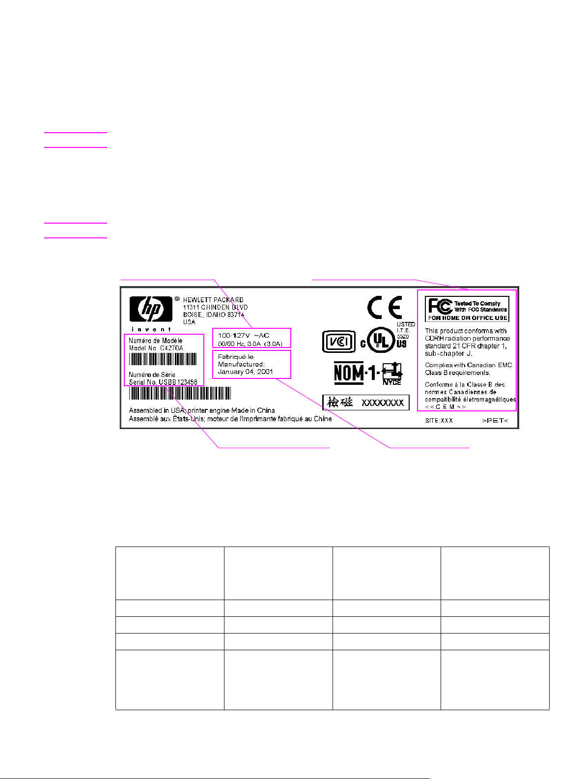
Identification
The model number and serial number are listed on an identification label located on the back cover.
The model number is alphanumeric, such as C4270A.
Note There is a user-accessible label inside the right door of the print engine.
The serial number contains information about the country/region of origin and the revision level,
production code, and production number of the MFP. An example of a serial number is
USBB123456.
The identification label also contains electrical information and regulatory information (see figure 1).
Note The electrical information and regulatory information vary by country/region.
Electrical information Regulatory information
Model and serial number
Figure 1. Sample identification label
Specifications
Table 2. Physical specifications
Specification HP LaserJet 9000mfp HP LaserJet 9000mfp
Height 1,219.2 mm (48 in) 1,219.2 mm (48 in) 1,219.2 mm (48 in)
Width 1,276.4 mm (50.3 in) 2,299.6 mm (90.6 in) 2,501.13 mm (98.47 in)
Depth 1,084.6 mm (42.7 in) 1,084.6 mm (42.7 in) 1,084.6 mm (42.7 in)
Weight
(without print cartridge)
76.2 kg (167.64 lb) 3,000-sheet stacker
Manufacture date
with 3,000-sheet
stacker or 3,000-shee t
stapler/stacker
103.7 kg (228.62 lb)
3,000-sheet stapler/
stacker
106.7 kg (235.23 lb)
HP LaserJet 9000mfp
with multifunction
finisher
1,16.9 kg (257.72 lb)
C8523-90921 Product specifications 17
Page 18
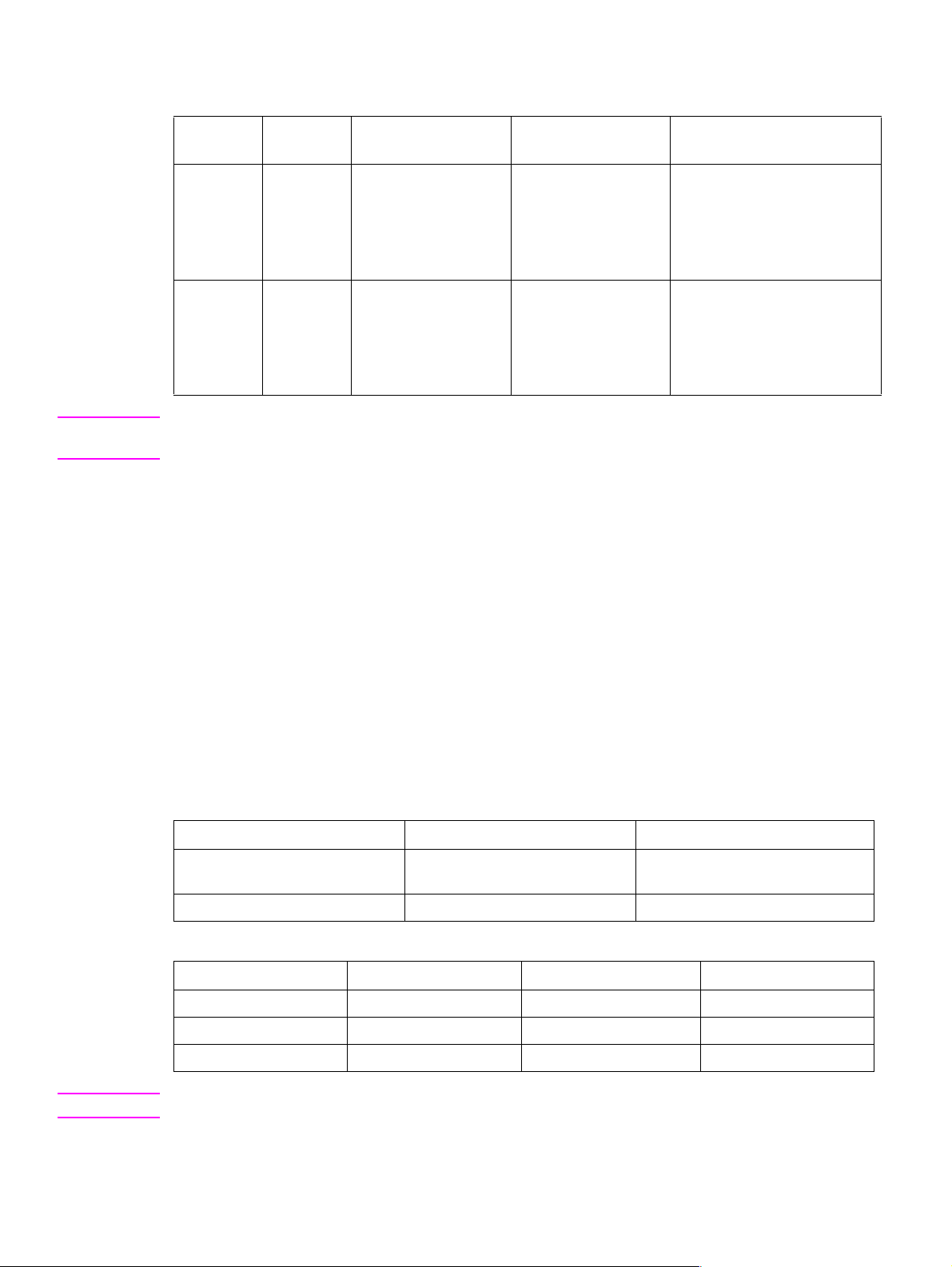
Table 3. Electrical specifications
Volts Frequency Amperes (amps) Watts (W) (typical) Thermal units per hour
(Btu/hr)
100-127 Vac
± 10 percent
220-240 Vac
± 10 percent
50/60 Hz
± 2 Hz
50/60 Hz
± 2 Hz
Minimum
recommended current
capacity =
15-amp dedicated
circuit
Minimum
recommended current
capacity =
6.5 amp
printing = 1,075 W
standby = 440 W
PowerSave 1 = 70 W
low power = 230 W
off = .5 W
ADF printing = 1,130 W
printing = 1,070 W
standby = 415 W
PowerSave 1 = 70 W
low power = 230 W
off = 1.3 W
ADF printing = 1,075 W
printing = 3,670 Btu/hr
standby = 1,500 Btu/hr
PowerSave 1 = 240 Btu/hr
low power = 785 BTu/hr
off = 1.7 Btu/hr
ADF printing = 3,860
printing = 3,650 Btu/hr
standby = 1,420 Btu/hr
PowerSave 1 = 240 Btu/hr
low power= 785 Btu/hr
off = 4.5 Btu/hr
ADF printing = 3,670
WARNING! Po wer requirements are based on the region where the MFP is sold. Do not conv ert operating voltages.
This can damage the MFP and void the product warranty.
The electrical and environmental specifications must be maintained to ensur e the proper operation of
the MFP. Consider the following points before installing the MFP:
l Install the MFP in a well-ventilated, dust-free area.
l Install the MFP on a level, flat surface that can support its size and weight. Do not install on
carpet or on other soft surfaces. Make sure all four MFP feet are level.
l Make sure the power supp ly circui try is adequate. (See “Product specifications” on page 17.)
l Install the MFP where temperature and humidity are st able, with no abrupt changes (away from
water sources, humidifiers, air conditioners, refrigerators, or other major appliances). (See
“Product specifications” on page 17.)
l Install away from direct sunlight, areas that experience vibration, open flames, ammonia fumes,
ultrasonic heaters, and devices that emit a magnetic field. If the MFP is placed near a window,
make sure the window has a curtain or blind to block direct sunlight.
l Maintain enough space around the MFP for proper access and ventilation. (See “Space
requirements” on page 28.)
Table 4. Environmental specifications
Operating/printing Storage/standby
Temperature
(MFP and print cartridge)
Relative humidity 20 percent to 80 percent 15 percent to 90 percent
10 degrees to 32.5 degrees C
(50 degrees to 90.5 degr e e s F)
-20 degrees to 40 degrees C
(-4 degrees to 104 degrees F)
Table 5. Noise level specifications
Operator position Bystander (1m) Sound power
Copying at 50 ppm L
Idle L
PowerSave inaudible inaudible inaudible
57 db(A) L
Pam
40 db(A) L
Pam
60 db(A) L
Pam
40 db(A) L
Pam
7.4 bels(A)
WAd
5.7 bels(A)
WAd
Note Testing per International Standards Organization (ISO) 9296.
18 Chapter 1 Product information C8523-90921
Page 19
Product overview
Assembly identification
For service issues and section identification, the MFP has been separated into three sections.
l copy/scan engine
l print engine
l finishing device
Copy/scan engine
Finishing device
Figure 2. Assembly identification
Note A finishing device is required with the HP LaserJet 9000mfp.
Print engine
C8523-90921 Product over view 19
Page 20
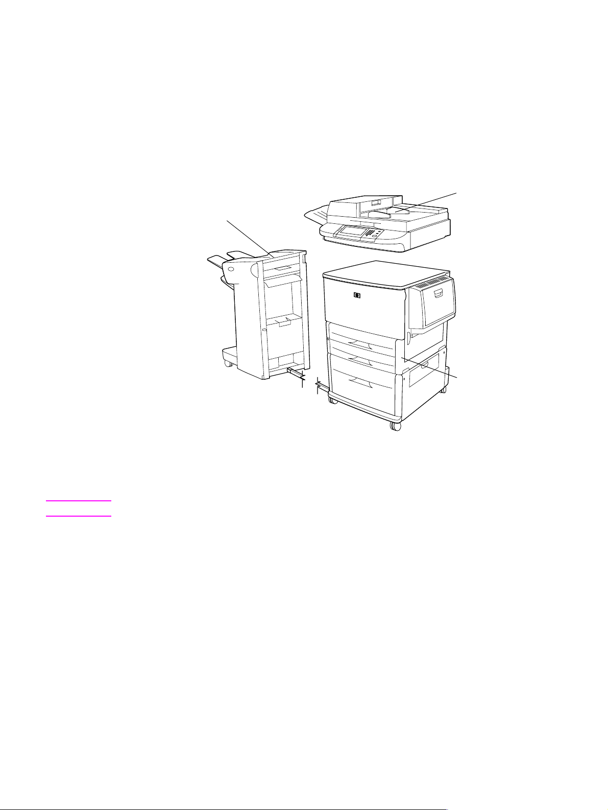
External assembly locations
ADF output bin
Control panel
Bin 1
Bin 2
Front door
Power button
Finishing device
(3000-sheet
stacker shown)
Tray 3
Figure 3. External assembly locations (front view)
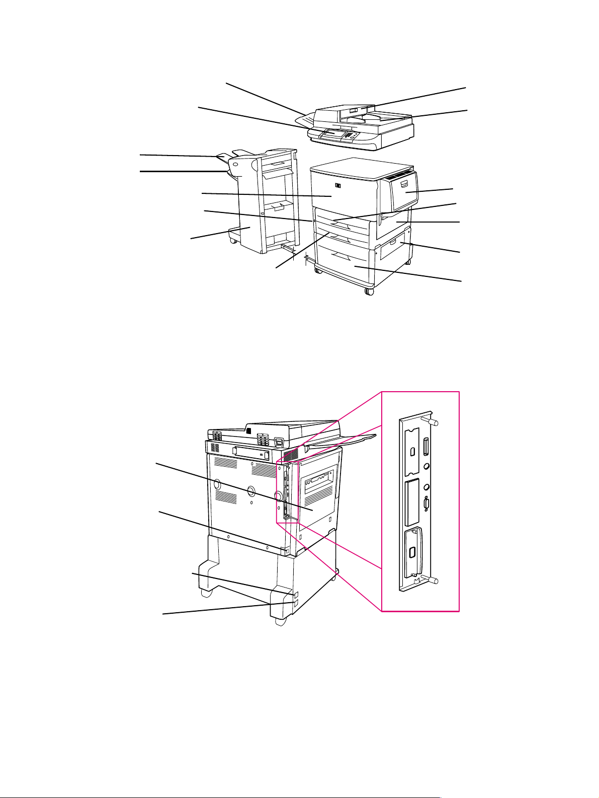
ADF feeder
ADF
Tray 1
Tray 2
Right door
Vertical
transfer door
Tray 4
Left door
Power-cord
connector
Paper-handling
power connector
Tray 4 power-cord
connector
Figure 4. External assembly locations (back view)
Interface
connection
panel
20 Chapter 1 Product information C8523-90921
Page 21
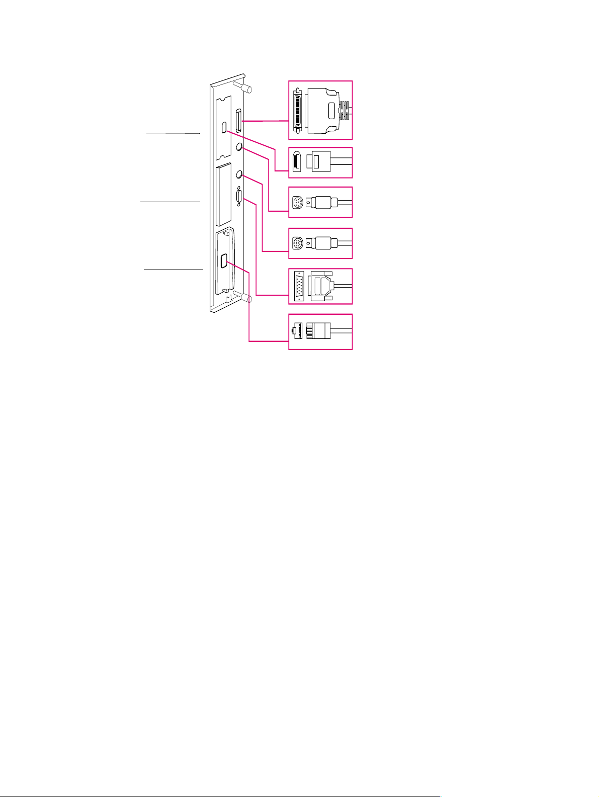
Interface connections
Copy
connect
card
Hard
disk
Jetdirect
card
Figure 5. Interface connections
Parallel connector
High-speed
copy-connect
connector
Foreign interface
connector
HP Fast InfraRed Connect
(optional IR pod)
HP Jet-Link connector
(accessories connector)
HP Jetdirect print
server RJ-45
connector
C8523-90921 Product over view 21
Page 22
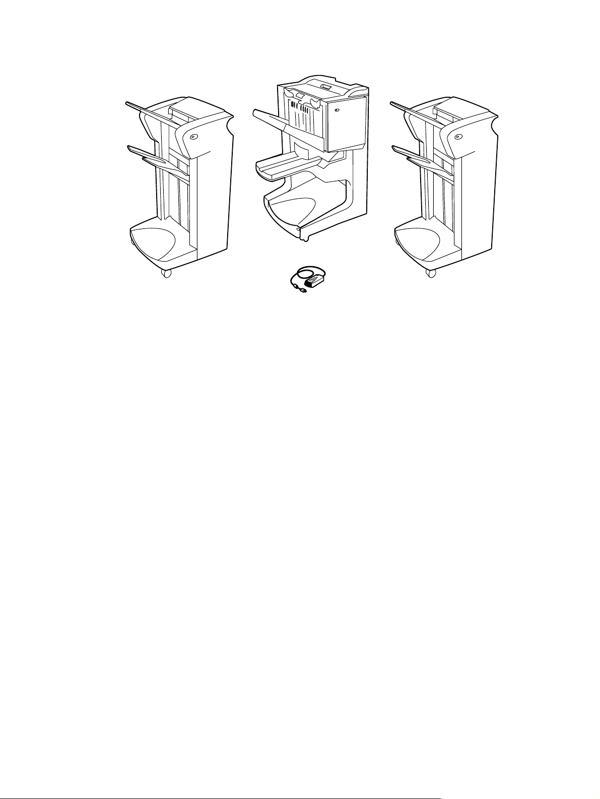
Accessories
Multifunction finisher
3,000-sheet stapler/stacker
Figure 6. Accessories
Optional HP Fast
3,000-sheet stacker
InfraRed Connect pod
22 Chapter 1 Product information C8523-90921
Page 23

Regulatory information
For regulatory information and requirements , FCC regula tio ns, and declaration of confo rmity, please
see the start guide.
For environmental product stewardship program information, please see the use guide.
Service approach
Repair of the MFP normally begins with a three-step process:
1 Isolate the problem to the major system (the host computer, the network and/or server, or the
MFP).
2 Determine whether the problem is located in the print engine, the copy/scan engine, or the
finishing device.
3 Troubleshoot the problem using “Malfunction troubleshooting” in chapter 7.
Once a faulty part is located, repair is usually accomplished by assembly-level replacement of field
replaceable units (FRUs). Some mechanical assemblies can be repaired at the subassembly level.
Hewlett-Packard does not support replacement of components on the printed circuit assemblies.
Parts and supplies
Information about ordering
“Ordering parts” in chapter 8 of this manual contains FRU and replacement part numbers.
Replacement parts can be ordered from the HP Customer Support (HPCS) organization.
“Consumables, supplies, accessories, FRUs, and documentation” in chapter 8 of this manual
contains information about products specifically designed for this MFP. Order accessories from
HPCS.
Note See “W orldwide service and support offices” on page 25 to find information for a local HP office in the
appropriate region.
HPCS phone listings
l HPCS (for U.S.)
(1) (800) 752-0900
l HPCS (for Canada)
(1) (800) 387-3867
l HPCS (for Europe)
(49 7031) 142253
Exchange program
HP might offer remanufactured assemblies for parts. These can be ordered through HPCS.
Warranty
For warr anty information and requirements , see the start guide.
Limited warranty for the print cartridge
For print cartridge warranty information, see the start guide.
C8523-90921 Regulatory information 23
Page 24

Service and support
World Wide Web
Print drivers, updated HP MFP firmware, and product and support information can be obtained from
the following URLs:
l U.S., http://www.hp.com/support/lj9000
l Europe, http://www.hp .com/support/lj9000
l China, ftp://www.hp.com.cn/support/lj9000
l Japan, ftp://www.jpn.hp.com/support/lj9000
l Korea, http://www.hp.co.kr/support/lj9000
l Taiwan, http://www.hp.com.tw/support/lj9000, or the local driver we bsite, http://www.dds.com.tw
HP support assistant CD-ROM
This support tool offers a comprehensive online information system designed to provide technical
and product information about He wlett-Packard products. To subscribe to this quarterly service in the
U.S. or Canada, call (1 ) (800) 457-1762 . In Hong Kong SAR, Indonesia, Malaysia, or Singapore, call
Mentor Media at (65) 740-4477.
HP-authorized resellers and support
To locate HP-authorized resellers and support, call (1) (800) 243-9816 in the U.S. or
(1) (800) 387-3867 in Canada. See “Worldwide service and support offices” on page 25 for areas
outside of North America.
HP service agreements
Call (1) (800) 743-8305 in the U.S. or (1) (800) 268-1221 in Canada.
HP PartnerCare
You can use the following information to contact HP PartnerCare:
l PartnerShip Web. http://www.partner.americas.hp.com
e-mail at websupport@mnl.com
l Connect Online. http://www.connect-online.hp.com
e-mail at PTS, INFOLINE (HP-Germany, exgen1)
l Asia Pacific countries/regions. http://partnercare.asiapac.hp.com/
l Canada Partner. http://www.canada.hp.com
l Latin America. http://www.conecta.latinamerica.hp.com
e-mail at SUPPORT-TEAM,LAR (HP-Miami, exgen1)
24 Chapter 1 Product information C8523-90921
Page 25

Worldwide service and support offices
l For the U.S., call (1) (208) 323-2551 Mon day through F riday from 6 A.M. to 6 P.M., Mountain time.
l For Canada, call (1) (90 5) 206- 4663 o r (1) (800) 38 7-386 7 Mond ay through Friday from 8 A.M. to
8
P.M., Mountain time.
l For customers outside of North America, use the follo wing list and call the appropriate telep hone
number for the country or region.
Europe
l Austria: 43 (0)810 00 6080
l Belgium
Dutch: 32 (0)2 626-8806
French: 32 (0)2 626-8806
l Czech Republic: 42 (0)2 6130 7310
l Denmark: +45 39 29 4099
l International English: +44 (0)207 512 52 02
l Finland: 358 (0)203 47 288
l France: 33 (0)1 43 62 34 34
l Germany: 49 (0)180 52 58 143
l Greece: +30 (0)1 619 64 11
l Hungary: +36 (0)1 382-1111
l Ireland: +353 (0)1 662 5525
l Italy: 39 02 264 10350
Africa and Middle East
l Egypt: +202 7956222
l International English: +44 (0)207 512 52 02
l Israel: +972 (0)9 9524848
l South Africa
Inside RSA: 086 000 1030
Outside RSA: +27-11 258 9301
l Netherlands: 31 (0)20 606 8751
l Norway: 47 22 11 6299
l Poland: +48 22 865 98 00
l Portugal: 351 21 3176333
l Romania: +40 1 315 44 42 (or 01 3154442)
l Russian Federation
Moscow: +7 095 797 3520
St. Petersburg: +7 812 346 7997
l Spain: +34 902 321 123
l Sweden: +46 (0)8 619 2170
l Switzerland: +41 (0)848 80 11 11
l Tu rkey: +90 212 221 69 69
l Ukraine: +7 (380-44) 490-3520
l U.K.: +44 (0)207 512 52 02
l United Arab Emirates, Bahrain, Jordan, Kuwait,
Lebanon, Oman, Palestine, Qatar, Saudi Arabia,
and Yemen: 971 4 883 8454
Asia-Pacific countries/regions
l Australia: (03) 8877 8000
l China: +86 (0)10 6564 5959
l Hong Kong SAR: +85 (2) 2802 4098
l India: +91 11 682 6035
l Indonesia: +62 (21) 350-3408
l Japan: +81 3 3335-8333
l Republic of Korea
Seoul: +82 (2) 3270-0700
Outside Seoul: 080 999-0700
Latin America
l Argentina: 0810-555-5520
l Brazil
Greater Sao Paulo: (11) 3747-7799
Outside Greater São Paulo: 0800-157751
l Chile: 800-22-5547
l Guatemala: 800-999-5305
l Malaysia: +60 (3) 295 2566
l New Zealand: +64 (9) 356 6640
l Philippines: +63 (2) 867 3551
l Singapore: +65 272 5300
l Taiwan: +886 (2) 2717 0055
l Thailand: +66 (2) 661 4000
l Vietnam: +84 (0) 8 823 4530
l Mexico
Mexico City: 52-58-9922
Outside Mexico City: 01-800-472-6684
l Peru: 0-0800-10111
l Puerto Rico: 1-877-2320-589
l Venezuela
Caracas: 207 8488
Outside Caracas: 800 47 777
C8523-90921 Service approach 25
Page 26

26 Chapter 1 Product information C8523-90921
Page 27

2 Product requirements
Chapter contents
Space requirements . . . . . . . . . . . . . . . . . . . . . . . . . . . . . . . . . . . . . . . . . . . . . . . . . . . . . . . . . . . 28
Setup. . . . . . . . . . . . . . . . . . . . . . . . . . . . . . . . . . . . . . . . . . . . . . . . . . . . . . . . . . . . . . . . . . . . . . .30
Initial setup . . . . . . . . . . . . . . . . . . . . . . . . . . . . . . . . . . . . . . . . . . . . . . . . . . . . . . . . . . . . . . .30
Unpacking the MFP . . . . . . . . . . . . . . . . . . . . . . . . . . . . . . . . . . . . . . . . . . . . . . . . . . . . . . . .31
Removing the MFP from the shipping pallet . . . . . . . . . . . . . . . . . . . . . . . . . . . . . . . . . . . . . .32
Initial hardware setup . . . . . . . . . . . . . . . . . . . . . . . . . . . . . . . . . . . . . . . . . . . . . . . . . . . . . . .3 3
Installing the finishing device . . . . . . . . . . . . . . . . . . . . . . . . . . . . . . . . . . . . . . . . . . . . . . . . .35
Testing MFP printing and copying functions . . . . . . . . . . . . . . . . . . . . . . . . . . . . . . . . . . . . . . 36
C8523-90921 Chapter contents 27
Page 28
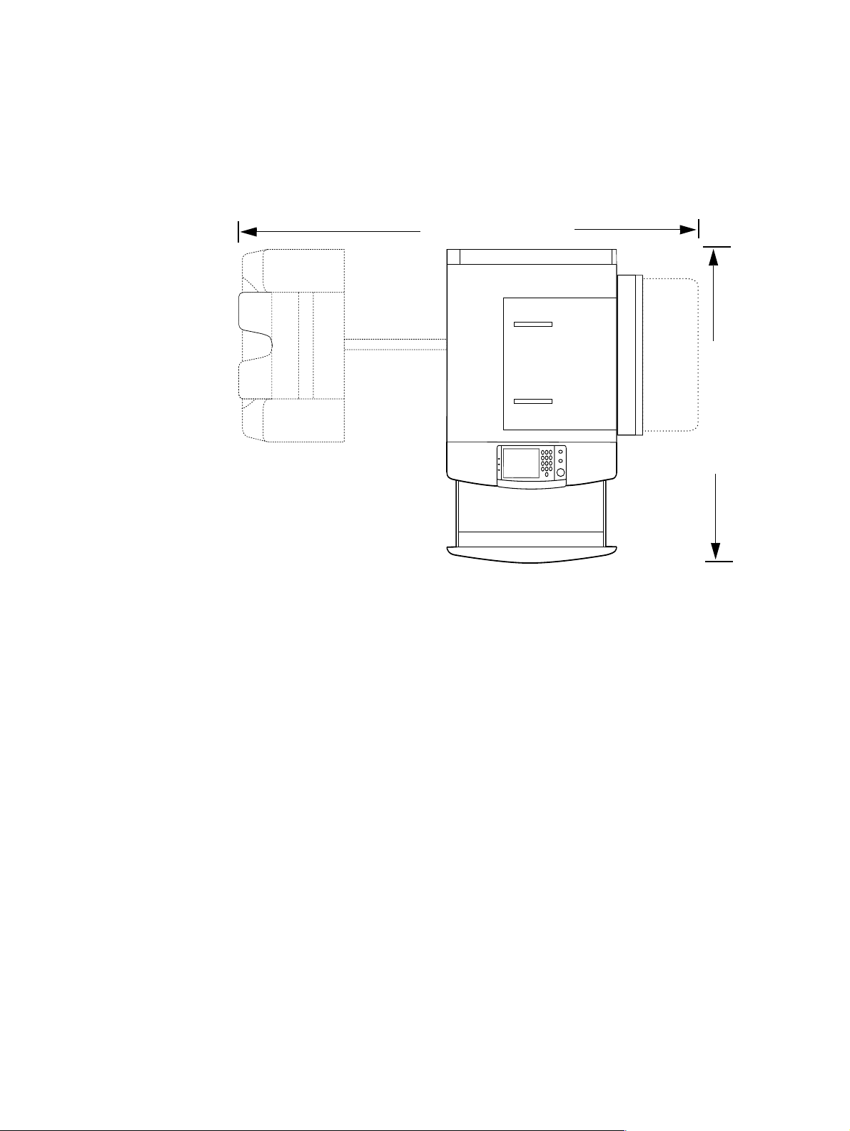
Space requirements
The dimensions of the shipping box that contains the HP LaserJet 9000mfp are 40 inches wide, 36
inches deep, and 57 inches hi gh. The customer m ust locate a do or or receiving area lar ge enough to
accept delivery of the shipping box.
MFP physical dimensions
2501.1 mm (98.5 in)
1084.6 mm (42.7 in)
Figure 7. MFP space requirements with a finishing device (3,000-sheet stapler/st acker shown) (top
view)
28 Chapter 2 Product requirements C8523-90921
Page 29
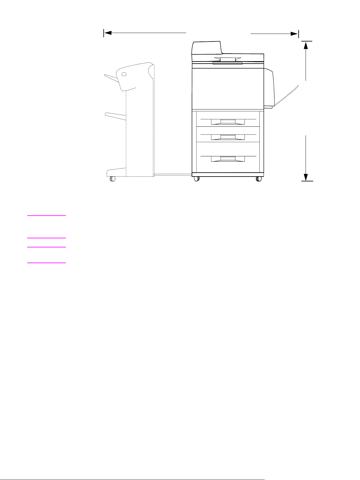
2501.1 mm (98.5 in)
1219.2 mm (48 in)
Figure 8.
MFP space requirements with a finishing device (3,000-sheet stapler/st acker shown) (front
view)
Note Before remo ving th e p lastic wr a pp ing ar ound t he box, make sure t hat ade qua te spa ce is availab le to
unpack the MFP and to roll the produ ct off of the shipping p allet. At least 1 0 f e et of clear ance arou nd
the box is required to remove all the shipping materials.
Note The front of the shipping bo x contains a slot that, when op ened, rev eals the softw are, the manual, and
power cords.
C8523-90921 Space requirements 29
Page 30

Setup
Initial setup
The initial MFP setup includes the following steps:
l Remove the MFP from the box.
l Set up and install the MFP.
l Set up and install the finishing device.
l Verify installation.
l Familiarize yourself with the MFP.
Note The initial setup package does not include any software or network setup. Do not load any printer
software or connect the MFP to the netw ork, ev en if the customer has an e xistin g network connection
in use. If an administrator does not, problems can occur to the network connection.
The shipping box contains the following items:
l HP LaserJet 9000mfp
l One or two power cords
Note The 110-volt MFP has two power cords, and the 220-volt MFP has one y-power cord.
l ADF output bin
l High-speed copy connect cable
l Control panel overlay
l Print cartridge
l Printer software on CD-ROM (includes the user introduce guide)
l Start guide
l Finishing device
Note The finishing device is delivered in a separate box.
Note The MFP is delivered with the duplexer, tray 1, and tray 4 installed.
30 Chapter 2 Product requirements C8523-90921
Page 31

Unpacking the MFP
1 Remove the plastic wrap from the shipping box.
2 Remove the two white, plastic shipping locks, and then remove the top of the box. Pull the locks
straight out to remove them from the box.
3 Remove the six remaining shipping locks that hold the sides in place.
4 Remove the reinforcing ribbon from the top of the box.
5 Carefully remove the sides of the box.
Note Four corner supports in the box can fall out when the sides are removed.
6 Remove and set aside the bag that co ntains the print cartridge (located on the top of t he printer).
Also remove the manual, cables, and software from the front piece of Styrofoam.
7 Remove the ramps (callout 1) by gently lifting them up. The ramps are located near the back
piece of Styrofoam.
2
1
Figure 9. Unpacking the MFP
8 Lift the two Styrofoam pieces away from the MFP.
9 Remove the plastic wrap from the MFP, and set aside the ADF output bin.
2
C8523-90921 Setup 31
Page 32

Removing the MFP from the shipping pallet
1 Break apart the ramps and push them into the slots on the front of the shipping pallet (callout 1).
2
2
1
Figure 10. Removing the MFP from the shipping pallet (1 of 2)
2 Unlock the wheels on tray 4 and point them forward so that they line up with the ramps.
3 Hold the MFP behind the wheels on tray 4 (callout 2) and ease it off of t he wood supports.
WARNING! Do not remove the MFP b y holding ot her parts of the MFP. This can result in damage to the MFP and
injury to the people lifting the MFP.
2
2
2
Figure 11. Removing the MFP from the shipping pallet (2 of 2)
4 Carefully move the MFP off the supports and onto the ramps. Support the front of t he MFP while
rolling it off of the shipping pallet.
32 Chapter 2 Product requirements C8523-90921
Page 33

Initial hardware setup
1 Press the shipping lock (callout 1), located on the left side of the scan engine , to war d the fr ont of
the MFP to unlock it.
Note Show the user where the shipping lock is located. Before the MFP can be moved, the flatbed optical
unit must be “parked” and locked. To lock the carriage, touch MENUS, then CONFIGURE DEVICE, touch
RESETS, touch LOCK CARRIAGE, and then engage the mechanical lock.
2
2
1
Figure 12. Initial hardware setup (1 of 4)
2 Open the left door.
3 Pull the shipping tape straight ba ck to remove the two fuser shipping locks. Make sure the fuser
levers ar e in the “down” position before printing.
4 Remove the remainder of the orange shipping tape inside th e left door.
5 Open trays 2, 3, and 4, and remove the shipping tape and the tray locks (tw o per tray).
6 Make sure that the custom/standard switch is in the “standard” position. Show the user where to
locate this switch and explain its purpose.
7 Open the top of the ADF and pull out the packing material (callout 2).
2
2
2
Figure 13. Initial hardware setup (2 of 4)
C8523-90921 Setup 33
Page 34

8 Install the high-speed copy connect cable (callou t 3). Show the user t he shape of the connectors ,
and how the connectors match up.
CAUTION Make sure that the high-speed co py conn ect cable is install ed correctly. The cable can be be installed
incorrectly if it is forced.
Figure 14. Initial hardware setup (3 of 4)
9 Install the two copy processor board (CPB) protectors (callout 4) on the back of the MFP.
2
2
2
2
3
4
Figure 15. Initial hardware setup (4 of 4)
10 Install the ADF output bin.
11 Open the front door and install the print cartridge.
Note The print cartridge does not have a pull tab.
Note The toner seal automatically rolls up when a new print cartridge is installed in the printer. The motor
used to drive the OPC (imaging drum) is initializ ed in the r everse direction, which rolls t he to ner se al
onto a spindle inside the print cartridge. The noise the printer makes when this occurs is normal.
34 Chapter 2 Product requirements C8523-90921
Page 35

Installing the finishing device
The MFP is delivered with a finishing de vice . The f inishing de vice co mes in its own bo x, and m ust be
set up and installed with the MFP. The following are finishing devices:
l 3,000-sheet stacker
l 3,000-sheet stapler/stacker
l Multifunction finisher
Note Make sure that the printer and finishing device are installed on a level surface so that they function
correctly.
1 Position the printer in its permanent location, allowing room to install the finishing device.
2 Lock the front wheels on the printer.
3 Open the box that contains the finishing de vice and remove the packing material. The box
includes two bins: a face-up bin (callout 1), and a stacker bin or a stapler bin (callout 2).
Note The multifunction finisher is delivered with the bins installed.
1
2
2
2
Figure 16. Installing the finishing device (1 of 2)
4 Place the finishing device in upright position.
5 Remove all of the orange packing materials and tape from the finishing device and the cables.
6 Position the finishing device on the left side of the printer.
7 Lower the connecting rod to a horizontal position.
8 Place the end of the connecting rod into the U-shaped metal slot on tray 4 and align the
connecting rod with the gray alignment label.
9 Slide the blue plastic bracket into the metal slot until it locks into place.
10 Connect the Jet-Link cable to the printer by attaching it to the connector labeled “Finishing
Device”.
Note Make sure that the Jet-Link cable is connected securely to the printer. The finishing device will not
operate unless the Jet-Link cable is connected.
11 Install the power cord(s).
12 Connect the power cord on the finishing device to the upper connection on tray 4.
13 Connect the printer power cord to the printer.
C8523-90921 Setup 35
Page 36

14 Connect the tray 4 power cord to tray 4.
15 Slide the finishing device toward the MFP and lock it in place.
Note Adjust the blue lev elers on the finishing device to mak e sure no gap exists betwe en the finishing device
and the MFP.
16 To attach the stacker bin, align the slots on the stacker bin with the metal bar on the finishing
device. Push in the stacker bin firmly.
Note Locate the paper stop clips and mak e sure the y cradle t he connecting rod. Th e graphic be low (callout
3) indicates the incorrect installation of the paper stop clips.
2
2
Figure 17. Installing the finishing device (2 of 2)
17 Attach the face-up bin.
18 Press the power button to turn on the MFP. The READY message appears on the control panel
when the MFP has warmed up.
19 Make sure the LEDs on the front of the finishing device, tray 4, and the MFP are green. This
indicates that the finishing device and the MFP are functional.
3
Testing MFP printing and copying functions
1 Adjust the paper guides in the trays for letter- or A4-size paper. Load paper in each tray.
2 Print a configuration page from the MFP control panel.
3 Make a copy of the configuration page by placing it on the glass.
4 Make a copy of the configuration page using the ADF.
36 Chapter 2 Product requirements C8523-90921
Page 37

3 Product configuration
Chapter contents
Control panel. . . . . . . . . . . . . . . . . . . . . . . . . . . . . . . . . . . . . . . . . . . . . . . . . . . . . . . . . . . . . . . . .38
Control panel layout . . . . . . . . . . . . . . . . . . . . . . . . . . . . . . . . . . . . . . . . . . . . . . . . . . . . . . . .38
Settings and defaults. . . . . . . . . . . . . . . . . . . . . . . . . . . . . . . . . . . . . . . . . . . . . . . . . . . . . . . . . . .41
Setting the display language. . . . . . . . . . . . . . . . . . . . . . . . . . . . . . . . . . . . . . . . . . . . . . . . . . 41
Setting tray registration. . . . . . . . . . . . . . . . . . . . . . . . . . . . . . . . . . . . . . . . . . . . . . . . . . . . . .41
Print driver information . . . . . . . . . . . . . . . . . . . . . . . . . . . . . . . . . . . . . . . . . . . . . . . . . . . . . . 43
Factory default settings. . . . . . . . . . . . . . . . . . . . . . . . . . . . . . . . . . . . . . . . . . . . . . . . . . . . . .4 3
Control panel menus . . . . . . . . . . . . . . . . . . . . . . . . . . . . . . . . . . . . . . . . . . . . . . . . . . . . . . . . . . .46
Using a menu map . . . . . . . . . . . . . . . . . . . . . . . . . . . . . . . . . . . . . . . . . . . . . . . . . . . . . . . . .46
Retrieve job menu. . . . . . . . . . . . . . . . . . . . . . . . . . . . . . . . . . . . . . . . . . . . . . . . . . . . . . . . . . 47
Information menu . . . . . . . . . . . . . . . . . . . . . . . . . . . . . . . . . . . . . . . . . . . . . . . . . . . . . . . . . .47
Paper handling menu . . . . . . . . . . . . . . . . . . . . . . . . . . . . . . . . . . . . . . . . . . . . . . . . . . . . . . .47
Configure device menu. . . . . . . . . . . . . . . . . . . . . . . . . . . . . . . . . . . . . . . . . . . . . . . . . . . . . .49
Remote firmware upgrade. . . . . . . . . . . . . . . . . . . . . . . . . . . . . . . . . . . . . . . . . . . . . . . . . . . . . . .52
Downloading the new firmware to the MFP . . . . . . . . . . . . . . . . . . . . . . . . . . . . . . . . . . . . . .52
Using HP Web JetAdmin . . . . . . . . . . . . . . . . . . . . . . . . . . . . . . . . . . . . . . . . . . . . . . . . . . . .53
C8523-90921 Chapter contents 37
Page 38

Control panel
Control panel layout
The control panel includes a touch-screen graphical display, three job-control buttons, a numeric
keypad, and three light-emitting diode (LED) indicator lights.
Touch-screen graphical display
Ready light
Data light
Attention
light
Figure 18. Control panel layout
Numeric keypad
Reset
Stop
Start
38 Chapter 3 Product configuration C8523-90921
Page 39

Control panel features
Table 6. Control panel features, and key functions
Feature or key Function
T ouch-screen graphical
display
Ready light
Data light
Attention light
RESET
STOP
START
Numeric keypad
l Provides access to settings, help screens, copy functions, and shows device
status.
l Off—the product is offline or has an error.
l On—the product is ready.
l Blinking—the product is going offline.
l Off—the product has no data to print.
l On—the product has data to print but is offline.
l Blinking—the product is processing the data.
l Off—the product has no error.
l On—the product has a critical error; turn power off and then on.
l Blinking—action is required; see the graphical display.
Resets the job settings to factory or user-defined default values.
l
Cancels the active job.
l
Begins a copy job, starts digital sending, or continues a job that has been
l
interrupted.
l Allows for input of numeric values.
Touch-screen graphical display layout
Menu tab Help tab Status bar Number of copies selected
Page
orientation
MENU HELP READY
icon
Original
section
Original
page icon
button modification
Figure 19. Touch-screen graphical display layout
ENHANCE
ImageReduce/Enlarge
section
Send
options
button
Copy
section
Copy
page icon
Contrast
control
C8523-90921 Control panel 39
Page 40

Touch-screen graphical display features
The touch-screen graphical display provides access to settings, help screens, copy f unctions, and
shows device status. User attention messages are shown in a pop-up window with distinct text and
codes. See “Troubleshooting with control panel messages” in chapter 7.
Table 7. Touch-screen graphical display features and functions
Feature Function
Status bar l Shows current device status, number of copies, and menu and Help options.
Menu
l Provides access to “What is this?” or “Show me how” Help options.
Help
l Provides access to settings, such as paper-handling and device configuration.
Original
Copy
Send Options
Reduce/Enlarge
Contrast Control
HELP
Enhance l Allows access to the screen that contains enhancement features.
Enhance
l Shows settings that describe the original document. The product automatically
detects document size.
l Shows settings that describe the output features of the document.
l Allows you to send your documents using e-mail.
l Reduces or enlarges the size of the scanned image.
l Increases or decreases the brightness of the scanned image.
Allows access to “What is this?” Help. This feature is embedded in the touch-
l
screen menus.
40 Chapter 3 Product configuration C8523-90921
Page 41

Settings and defaults
Most of the MFP printing decisions are based on temporary settings or on factory defaults.
Note Most of the settings you send from software applications override MFP defaults.
Temporary settings are the values set through your software application for the current print job.
Temporary settings remain in effect until the current print job is finished.
Control panel defaults are the values entered by selecting a control panel item on the touch screen
and then touching it. A bullet (
retains default se ttings even when power is turned off.
Factory defaults are preset at the factory and are the def ault values f or each menu item. Factory
default values are listed in table 8.
Setting the display language
Method 1
1 Using the touch scr ee n, tou ch MENU to open the menus.
2 Touch CONFIGURE DEVICE, and then press to scroll to system setup.
3 Touch SYSTEM SETUP, and then press to scroll to language.
) next to the item name indicates that it is now the default. The MFP
4 Touch LANGUAGE to activate the selection screen.
5 Select the language you want, and then touch OK.
Method 2
1 Press and hold START while turning on the device.
2 Hold START until all three error lights are illuminated at the same time.
3 Press or to scroll to the language you want, and then press START.
Setting tray registration
1 Using the touch scr ee n, tou ch MENU to open the menus.
2 Touch CONFIGURE DEVICE.
3 Touch PRINT QUALITY.
4 Touch SET REGISTRATION.
5 Touch SOURCE. Select the tray that you want to set registration.
6 Touch PRINT TEST PAGE.
7 The registration page prints. Follow the instructions on the page to complete the registration
setting.
Note The tray registration can only be performed using letter or A4 paper.
C8523-90921 Settings and defaults 41
Page 42

Figure 20. Registration page (1 of 2)
Figure 21. Registration page (2 of 2)
42 Chapter 3 Product configuration C8523-90921
Page 43

Print driver information
When you change a setting from the MFP control panel, the new setting becomes the MFP default
value. You can override most control panel settings through most software applications, or th rough
the print driver.
Factory default settings
The following table lists the def ault values for ea ch men u item, g rouped b y m enu . Selectin g RESTORE
FACTORY SETTINGS restores the MFP to these facto ry default settings.
Note The Web configuration tool is the preferred mechanism for setting the values. The ability to set these
values from the control pan el is only availab le when the embedded e-mail solution is being used. When
the Digital Send service is being used on the device, the se fields must be set throu gh the service and
cannot be set on the control panel.
.
Table 8. Factory default settings
Menu item Default value
Paper handling
Tray 1 mode= First
Configure device (originals)
Paper Size= Letter or A4
Number of sides= 1
Orientation= Portrait
Content= Mixed
Text/Photo mix= 4
Density= 4
Heavy paper= Off
Configure device (copying)
Number of sides= 1
Collate= On
Copies= 1
Staple= None
Configure device (enhancement)
Sharpness= 2
Background removal= 2
Configure device (sending) (E-mail)
Scan preference= Color
File type= PDF
Configure device (printing)
Copies= 1
Default paper size= Letter
Duplex= Off
Override A4/Letter= No
Manual feed= Off
C8523-90921 Settings and defaults 43
Page 44

Table 8. Factory default settings (continued)
Edge-to-edge override= No
Courier font= Regular
Wide A4= No
Print PS errors= Off
Configure device (printing) (PCL)
Form length= 60
Orientation= Portrait
Font source= Internal
Font number= 0
Font pitch= 10.00
Symbol set= PC-8
Append CR to LF= No
Configure device (print quality)
Resolution= Fastres 1200
RET= Medium
Economode= Off
Toner Density= 3
Small paper mode= Normal
Configure device (system setup)
Job storage limit= 32
Job held timeout= Off
PowerSave time= 90 minutes
Copy/send settings
Reset copy timeout= 60
Reset send timeout= 15
Hold off print job= On
Hold off time= 15
Scan ahead= On
Auto job interrupt= Off
Copy job interrupt= Off
Edge-to-edge copies= On
Audible feedback= On
Personality= Auto
Clearable warnings= Job
Auto continue= On
Cartridge low= Continue
Cartridge out= Continue
Jam recovery= Auto
Configure device (I/O)
I/O timeout= 15
Parallel input
44 Chapter 3 Product configuration C8523-90921
Page 45

Table 8. Factory default settings (continued)
High speed= Yes
Advanced functions= On
EIO 1 Jetdirect menu
TCP/IP
Enable= On
Config method= BOOTP
IPX/SPX
Enable= On
Frame typ e= Auto
Appletalk
Enable= On
DLC/LLC
Enable= On
Link Speed= Auto
Configure device (resets)
PowerSave= On
C8523-90921 Settings and defaults 45
Page 46

Control panel menus
Touch MENU on the touch-screen graphical display to cycle through the control panel menus. Each
menu is described in a separate table in this section. Menu items appear only if their associated
option is installed, or if their functions are activated.
All menus and their associated items are av a ilab le when the MFP is o nline. In menu mo de , if no item
is touched for approximately 60 seconds, t he system au tomatically r eturns to the top level and either
an existing error or one of the following is displayed:
l READY, if the MFP was online
l OFFLINE, if the MFP was offline
Menu map
From the control panel, you can print a menu map that shows the current MFP configuration.
Additional menu items can appear in the control panel, depending on the options currently installed
in the MFP. The following is a list of menus available from the control panel, and where to find
information about each.
l Retrieve job menu (page 47)
l Information menu (page 47)
l Paper handling me nu (page 47)
l Configure device menu (page 49)
l Diagnostics menu (page 51)
l Service menu (page 51)
Using a menu map
To see the current settings for the menus and items available in the control panel, select or print a
menu map.
Select an item from the menu map
1 Touch MENU on the touch screen.
2 Touch the required menu.
3 Touch or to scroll to the page you want, and then touch the required item.
Print a menu map
1 Touch MENU on the touch screen.
2 Touch INFORMATION MENU.
3 Touch PRINT MENU MAP. A current menu map prints.
V alues t hat appe ar with a b ullet (
of these values can be overridden from the print driver or a user program. You might want to store
the menu map near the MFP for reference.
The contents of the menu map va ry, depending on the optional accessories installed in the MFP. For
a complete list of accessories or to change a control panel item and its values, see the following
tables.
) next to them are the cur rently select ed values for a sett ing. Many
46 Chapter 3 Product configuration C8523-90921
Page 47

Retrieve job menu
This menu contains stored-job information.
Table 9. Retrieve job menu
Item Explanation
NO STORED JOBS
[NAME OF CURRENT
]
JOB
This menu is displayed when there are no stored print jobs.
This menu shows a list of currently stored print jobs.
Information menu
This menu contains MFP information pages that give details about the MFP and its configuration.
Table 10. Information menu
Item Explanation
PRINT
MENU MAP
PRINT
CONFIGURATION
PRINT SUPPLIES
STATUS PAGE
PRINT USAGE PAGE
PRINT
FILE
DIRECTORY
The menu map shows the layout and current settings of the control panel menu item.
The configuration page shows the current MFP configuration. If an HP Jetdirect print
server card is installed, a Jetdirect configuration page will print as well. See
“Configuration page” in chapter 7.
The supplies status page shows the number of pages remaining for the print cartridge
and maintenance kit. Percentage of toner remaining as well as number of pages
remaining for all consumables are shown on this page.
The usage page contains information that can be used for cost analysis and
accounting.
The file directory shows information for all installed mass-storage devices. See “File
directory page” in chapter 7.
PRINT
The PCL font list show s all of th e PC L fonts currently available on the MFP.
PCL FONT LIST
PRINT
The PS font list shows all of the PS fonts currently available on the MFP.
PS FONT LIST
Paper handling menu
When paper-handling settings are correctly configured through the control panel, you can print by
choosing the type and size of paper from the print driver or software application.
Some items in this menu can be set from a software application or from the print driver (if the
appropriate driver is installed). Print-driver and software-application settings override control-panel
settings.
Table 11. Paper handling menu default settings
Item Values Explanation
TRAY 1 MODE=
FIRST
TRAY 1 SIZE=
LETTER
FIRST
LETTER
If TRAY 1 MODE=FIRST and paper is loaded in tray 1, the MFP
will pull paper from tray 1 first.
Set the value to correspond with the paper size currently
loaded in tray 1.
Note This item is only displayed if TRAY 1 MODE is
set to cassette.
C8523-90921 Control panel menus 47
Page 48

Table 11. Paper handling menu default settings (continued)
Item Values Explanation
TRAY 1 TYPE=
PLAIN
PLAIN
TRAY 2 SIZE=
LETTER
LETTER
TRAY 2 TYPE=
PLAIN
PLAIN
TRAY 3 SIZE=
LETTER
LETTER
TRAY 3 TYPE=
PLAIN
PLAIN
TRAY 4 SIZE=
LETTER
LETTER
TRAY 4 TYPE=
PLAIN
PLAIN
FUSER MODES PLAIN
Set the value to correspond with the paper type currently
loaded in tray 1.
Note This item is only displayed if TRAY 1 MODE is
set to cassette.
Set the value to correspond with the paper size currently
loaded in tray 2.
Set the value to correspond with the paper type currently
loaded in tray 2.
Set the value to correspond with the paper size currently
loaded in tray 3.
Set the value to correspond with the paper type currently
loaded in tray 3.
Set the value to correspond with the paper size currently
loaded in tray 4.
Set the value to correspond with the paper type currently
loaded in tray 4.
Configure the fuser mode associated with each paper type.
The fuser mode can be changed only from this menu option in
the control panel. Each value has three settings to choose
from: NORMAL, HIGH 1, and LOW.
48 Chapter 3 Product configuration C8523-90921
Page 49

Configure device menu
It is possible to gain access to some items in this menu either f rom a soft wa re application or f rom the
print driver (if the appropriate driver is installed). Print-driver and software-application settings
override control panel settings.
Table 12. Configure device menu
Item Values Explanation
ORIGINALS PAPER SIZE =
EXECUTIVE
NUMBER OF
SIDES = 1
ORIENTATION
CONTENT =
GRAPHIC
TEXT/PHOTO MIX
= 4
DENSITY
HEAVY PAPER
COPYING NUMBER OF
SIDES = 1
COLLATE = OFF
COPIES = 1
STAPLE = NONE
ENHANCEMENT SHARPNESS = 3
BACKGROUND
REMOVAL = 2
SENDING E-MAIL
PRINTING COPIES
DEFAULT PAPER
SIZE
DEFAULT CUSTOM
PAPER SIZE
DUPLEX
OVERRIDE
A4/LETTER
MANUAL FEED
EDGE-TO-EDGE
COURIER FONT
WIDE A4
PRINT PS ERRORS
PCL
Set the paper size, number of sides, and the type of content in
the original; the number of pages with text and graphics in the
original, and the density of the copy to be made.
Set the number of sides, the collation option, the number of
copies to create, and the stapling option for the copies produced
from the original.
Enhance the copy being produced.
Configure gateways and send preferences.
Set the default number of copies, standard and custom paper
sizes, output destination, and the default overrides for A4/letter,
edge-to-edge, and manual feed.
PRINT QUALITY SE T
REGISTRATION
RESOLUTION
Set the paper registration and print quality from this menu item.
Create a print engine cleaning page and set EconoMode in this
menu item.
SET
ECONOMODE
TONER DENSITY
SMALL PAPER
MODE
CREATE CLEANING
PAGE
C8523-90921 Control panel menus 49
Page 50

Table 12. Configure device menu (continued)
Item Values Explanation
SYSTEM SETUP JOB STORAGE
LIMIT
JOB HELD
TIMEOUT
POWERSAVE TIME
COPY/SEND
SETTINGS
PERSONALITY
CLEARABLE
WARNINGS
AUTO CONTINUE
CARTRIDGE LOW
CARTRIDGE OUT
JAM RECOVERY
LANGUAGE
I/O I/O TIMEOUT
PARALLEL INPUT
FIND SEND
GATEWAY
SMTP GATEWAY
LOAD GATEWAY
EIO 1 JET
DIRECT MENU
TEST SEND
GATEWAY
Set time and quantities for warnings and limits.
Set timings for the EIO slots.
RESETS RE STO RE
FACTORY
SETTINGS
POWERSAVE
LOCK CARRIAGE
CLEAR ADDRESS
BOOK
MESSAGE
Restore factory defau lt s.
50 Chapter 3 Product configuration C8523-90921
Page 51

Diagnostics menu
Use this menu to perform MFP and finishing device diagnostics.
Table 13. Diagnostics menu
Item Values Explanation
DIAGNOSTICS PR INT EVENT LOG
SHOW EVENT LOG
PAPER PATH TEST
SCANNER TESTS
CONTROL PANEL
SERVICE TEST
MFP and finishing device diagnostics. A service test can
be performed from this menu.
Service menu
Use this menu to enter the service mode.
Note The PIN number to enter the service menu is 00900001.
Table 14. Service menu
Item Values Explanation
SERVICE CL EAR EVENT
LOG
TOTAL PAGE
COUNT =
MAINTENANCE
COUNT =
MAINTENANCE
INTERVAL
= 350000
ADF COUNT =
FLATBED
COUNT =
ADF SIMPLEX
COUNT =
ADF DUPLEX
COUNT =
COPY SCAN
COUNT =
SEND SCAN
COUNT =
COPY PAGES
COUNT =
SCANNER
SETTINGS
SERIAL NUMBER
= XXXXX
COLD RESET
PAPER
Use the service menu after service has been performed on the
MFP and accessories. Cold-reset paper is set here.
C8523-90921 Control panel menus 51
Page 52

Remote firmware upgrade
The process for upgr ading MFP firmware involves three steps:
1 Determine the current level of firmware installed on the MFP.
2 Go to the http://www.hp.com/go/lj9000_firmware website and download the latest firmware.
3 See "Downloading the new firmware to the MFP" below to download the new firmware to the
MFP.
Downloading the new firmware to the MFP
You can send a remote firmware upgrade (RFU) to the MFP at any time. The MFP waits for all input/
output channels to become idle before turning power off and back on.
Note If the firmware upgrade involves a change in the format of NVRAM, the NVRAM settings will be lost
and must be reset again by the customer.
Microsoft® Windows® systems
Note Some Windows systems might require the f ollowing command to be performed at the command prompt
if the system receives a “time out” error during the MFP firmware upgrade process:
“mode lpt1:,,p”
If the MFP is shared on a network, then the following command can be issued from a command
prompt:
copy /b FILENAME \\SHARENAME\PRINTERNAME
where FILENAME is the name of the RFU file, SHARENAME is the name of the computer from
which the MFP is being shared, and PRINTERNAME is the MFP share name.
If the MFP is connected locally, then the RFU file can be sent directly to the MFP with a copy
command from a command prompt or MS-DOS
copy /b FILENAME PORTNAME
where FILENAME is the name of the RFU file, and POR TNAME is th e nam e of the appr opriate print
engine port (such as LPT 1).
You can also send the file through an infrared receiver (IR) pod.
®
window:
UNIX® systems
Any method that delivers the RFU file to the MFP will work, including:
$ cp /home/yourmachine/FILENAME /dev/parallel
in which /home/yourmachine/FILENAME contains the RFU file.
52 Chapter 3 Product configuration C8523-90921
Page 53

Using HP Web JetAdmin
Note This procedure requires that HP Web JetAdmin version 6.1 or later is installed.
Complete the following steps to upgrade the firmware for a single MFP through HP Web JetAdmin
after downloading the RFU file from the HP website.
1 Start HP Web JetAdmin.
2 Enter the internet protocol (IP) address or IP hostname of the MFP in the Quick Device Find
field, and then click Go. The printer Status window appears.
3 Click the right arrow on the toolbar to show the Update button.
4 Click Update.
5 When prompted for the type of update to perform, click Update Printers, and then click
Continue.
6 Under Upload new firmware image:, click Browse to locate the RFU file you downloaded from
the http://www.hp.com/go/lj9000_firmware website.
7 Click Upload to move the RFU file from the hard drive to the HP Web JetAdmin server.
8 Refresh the browser.
9 Select the RFU file from the Select new firmware version: drop-down menu.
10 Click Update Firmware. HP Web JetAdmin sends the selected RFU file to the MFP.
Also, HP Web JetAdmin 6.1 or later can be used to perform multiple installations.
1 Start HP Web JetAdmin.
2 Create a device group. A simple way to do this is to:
a. Click Devices on the Choose drop-down menu.
b. Click Device Model from the Filter drop-down menu.
c. Type “iy9000lw” in the Criteria (Optional) field.
d. Click Go.
3 In the Device List, select the printers you want to include in the group and then click Create
Group.
4 When prompted , typ e a na m e for the new device group, and then click OK.
5 Click Update.
6 When prompted for the type of update to perform, click Update Printers, and then click
Continue.
7 From the list of HP Devices, select the printers to be upgraded, or click Select All.
8 Click Update to install the new MFP firmware.
C8523-90921 Remote firmware upgrade 53
Page 54

54 Chapter 3 Product configuration C8523-90921
Page 55

4 Product maintenance
Chapter contents
Cleaning the MFP and accessories. . . . . . . . . . . . . . . . . . . . . . . . . . . . . . . . . . . . . . . . . . . . . . . .56
General cleaning. . . . . . . . . . . . . . . . . . . . . . . . . . . . . . . . . . . . . . . . . . . . . . . . . . . . . . . . . . .56
ADF cleaning . . . . . . . . . . . . . . . . . . . . . . . . . . . . . . . . . . . . . . . . . . . . . . . . . . . . . . . . . . . . .57
Glass cleaning . . . . . . . . . . . . . . . . . . . . . . . . . . . . . . . . . . . . . . . . . . . . . . . . . . . . . . . . . . . .63
C8523-90921 Chapter contents 55
Page 56

Cleaning the MFP and accessories
General cleaning
WARNING! In order to avoid shock hazard, turn the MFP and the finishing device off and unplug all power cords
before you begin these steps.
CAUTION Do not use ammonia-based cleaners on the print engine or finishing device. While cleaning the MFP,
be careful not to touch the transfer or delivery rollers. Skin oils on the roller can cause print-quality
problems.
l Clean the outside of the MFP with a water-dampened cloth.
l Clean the inside of the MFP with a dry, lint-free cloth.
l Clean the glass and the white vinyl calibration strips with an ammonia-based cleaner.
CAUTION The ADF and the glass are the only MFP components that can tolerate ammonia-based cleaners.
Keep the cleaners in a location away from the MFP. Only bring the dampened cloth near the MFP,
and never touch the cloth to any part of the print engine or finishing devices.
Promptly remove any dampened cloth after the cleaning procedure is accomplished.
56 Chapter 4 Product maintenance C8523-90921
Page 57

ADF cleaning
To clean the ADF delivery system
Clean the ADF only if it is visibly marked or dirty, or if you are experiencing a degradation of copy
quality (such as streaking).
WARNING! In order to av oid shock ha zard, turn the print engine and the finishin g devices of f and unplug all po wer
cords before you begin these steps.
1 Lift the ADF.
Figure 22. ADF delivery system (1 of 5)
2 Locate the top and bottom ADF glass strips.
Figure 23. ADF delivery system (2 of 5)
3 Clean the ADF glass strips by wiping them gently with a clean, damp, lint-free cloth. Use an
ammonia-based surface cleaner to dampen the cloth.
CAUTION The ADF and the glass are the only MFP components that can tolerate ammonia-based cleaners.
Keep the cleaners in a location away from the MFP. Only bring the dampened cloth near the MFP,
and never touch the cloth to any part of the print engine or finishing devices.
Promptly remove any dampened cloth after the cleaning procedure is accomplished.
C8523-90921 Cleaning the MFP and accessories 57
Page 58

4 Locate the white board.
Figure 24. ADF delivery system (3 of 5)
5 Locate the white, vinyl calibration strips.
Figure 25. ADF delivery system (4 of 5)
6 Clean the ADF backing and the calibration strips by wiping them with a clean, damp, lint-free
cloth. Use an ammonia-based surfa ce cleaner to dampen the cloth.
7 Close the ADF.
Figure 26. ADF delivery system (5 of 5)
58 Chapter 4 Product maintenance C8523-90921
Page 59

To clean the upper ADF glass strip
If you continue to experience poor copy quality, you might need to clean the upper ADF glass strip.
CAUTION Clean this area only if you see copy defects such as streaks, and you notice dust inside the glass strip.
Cleaning this area frequently could introduce dust into th e M FP.
WARNING! In order to avoid shock hazard, turn the MFP and the finishing device off and unplug all power cords
before you begin these steps.
1 Open the ADF feeder.
Figure 27. Upper ADF glass strip (1 of 4)
2 Locate the latch that releases the upper ADF glass strip. Push the latch to the left, and then pull
the latch down to expose the inside of the glass strip.
Figure 28. Upper ADF glass strip (2 of 4)
CAUTION Use dry cloth only in this area. Do not use solvent s, cleaners, water , or compressed air. Doing so could
severely da mage the MFP.
3 Gently wipe the glass with a dry, lint-free cloth.
C8523-90921 Cleaning the MFP and accessories 59
Page 60

4 Pull up the latch to return the glass strip to its normal position.
Figure 29. Upper ADF glass strip (3 of 4)
5 Close the ADF feeder.
Figure 30. Upper ADF glass strip (4 of 4)
60 Chapter 4 Product maintenance C8523-90921
Page 61

To clean the ADF rollers
If the user is experiencing poor scan quality or several misfeeds, the ADF rollers might need to be
cleaned.
CAUTION Clean the rollers only if the user e xperiences misf eeds or marks on the originals, or if y ou notice dust
on the rollers. Cleaning the rollers frequently could introduce dust into the MFP.
1 Lift the ADF.
Figure 31. ADF rollers (1 of 6)
2 Locate the delivery rollers.
3 Wipe the rollers gently with a clean, water-dampened, lint-free clot h.
Figure 32. ADF rollers (2 of 6)
CAUTION Do not pour water directly onto the rollers. Doing so might damage the MFP.
4 Close the ADF.
Figure 33. ADF rollers (3 of 6)
C8523-90921 Cleaning the MFP and accessories 61
Page 62

5 Open the ADF feeder.
Figure 34. ADF rollers (4 of 6)
6 Locate the registration rollers.
7 Wipe the rollers with a clean, water-dampened, lint-free cloth.
Figure 35. ADF rollers (5 of 6)
CAUTION Do not pour water directly onto the rollers. Doing so might damage the MFP.
8 Close the ADF feeder.
Figure 36. ADF rollers (6 of 6)
62 Chapter 4 Product maintenance C8523-90921
Page 63

Glass cleaning
To clean the glass
Clean the glass only if dirt is visible, or if you see poor copy quality (such as streaking).
Clean the glass surface by wip ing it gently with a clean, damp , lin t-free clot h. Use an ammonia -based
surface cleaner to dampen the cloth.
CAUTION The ADF and the glass are the only MFP components that can tolerate ammonia-based cleaners.
Keep the cleaners in a location away from the MFP. Only bring the dampened cloth near the MFP,
and never touch the cloth to any part of the print engine or accessories.
Promptly remove any dampened cloth after the cleaning procedure is accomplished.
Do not pour or spray liquids directly onto the glass.
Do not press hard on the glass surface. You might break the glass.
C8523-90921 Cleaning the MFP and accessories 63
Page 64

64 Chapter 4 Product maintenance C8523-90921
Page 65

5 Theory of operation
Chapter contents
Differences in print engines. . . . . . . . . . . . . . . . . . . . . . . . . . . . . . . . . . . . . . . . . . . . . . . . . . . . . .66
Mechanical structure . . . . . . . . . . . . . . . . . . . . . . . . . . . . . . . . . . . . . . . . . . . . . . . . . . . . . . . . . . .68
Motors and fans. . . . . . . . . . . . . . . . . . . . . . . . . . . . . . . . . . . . . . . . . . . . . . . . . . . . . . . . . . . . . . . 70
Basic block diagram . . . . . . . . . . . . . . . . . . . . . . . . . . . . . . . . . . . . . . . . . . . . . . . . . . . . . . . . . . .72
Basic system configuration . . . . . . . . . . . . . . . . . . . . . . . . . . . . . . . . . . . . . . . . . . . . . . . . . . . . . .73
Scanner unit systems . . . . . . . . . . . . . . . . . . . . . . . . . . . . . . . . . . . . . . . . . . . . . . . . . . . . . . .73
Scan mode . . . . . . . . . . . . . . . . . . . . . . . . . . . . . . . . . . . . . . . . . . . . . . . . . . . . . . . . . . . . . . .73
Power supply assembly. . . . . . . . . . . . . . . . . . . . . . . . . . . . . . . . . . . . . . . . . . . . . . . . . . . . . . . . .75
Power supply assembly . . . . . . . . . . . . . . . . . . . . . . . . . . . . . . . . . . . . . . . . . . . . . . . . . . . . .75
Low-voltage power supply circuit . . . . . . . . . . . . . . . . . . . . . . . . . . . . . . . . . . . . . . . . . . . . . .78
Scanner controller circuit . . . . . . . . . . . . . . . . . . . . . . . . . . . . . . . . . . . . . . . . . . . . . . . . . . . .80
Flatbed operation . . . . . . . . . . . . . . . . . . . . . . . . . . . . . . . . . . . . . . . . . . . . . . . . . . . . . . . . . . . . . 81
Flatbed document exposure control . . . . . . . . . . . . . . . . . . . . . . . . . . . . . . . . . . . . . . . . . . . .81
Flatbed optical drive control . . . . . . . . . . . . . . . . . . . . . . . . . . . . . . . . . . . . . . . . . . . . . . . . . .82
Flatbed optical unit operation . . . . . . . . . . . . . . . . . . . . . . . . . . . . . . . . . . . . . . . . . . . . . . . . .83
Flatbed document size detection . . . . . . . . . . . . . . . . . . . . . . . . . . . . . . . . . . . . . . . . . . . . . .84
ADF operation . . . . . . . . . . . . . . . . . . . . . . . . . . . . . . . . . . . . . . . . . . . . . . . . . . . . . . . . . . . . . . . .87
ADF document exposure control . . . . . . . . . . . . . . . . . . . . . . . . . . . . . . . . . . . . . . . . . . . . . .87
ADF document feed control . . . . . . . . . . . . . . . . . . . . . . . . . . . . . . . . . . . . . . . . . . . . . . . . . .88
ADF document size detection. . . . . . . . . . . . . . . . . . . . . . . . . . . . . . . . . . . . . . . . . . . . . . . . .90
ADF feeder sensors . . . . . . . . . . . . . . . . . . . . . . . . . . . . . . . . . . . . . . . . . . . . . . . . . . . . . . . .91
ADF document skew detection . . . . . . . . . . . . . . . . . . . . . . . . . . . . . . . . . . . . . . . . . . . . . . . . 92
Scanned data flow. . . . . . . . . . . . . . . . . . . . . . . . . . . . . . . . . . . . . . . . . . . . . . . . . . . . . . . . . . . . .93
Copy processor board. . . . . . . . . . . . . . . . . . . . . . . . . . . . . . . . . . . . . . . . . . . . . . . . . . . . . . . . . .94
CPB terminology. . . . . . . . . . . . . . . . . . . . . . . . . . . . . . . . . . . . . . . . . . . . . . . . . . . . . . . . . . .94
Scanning process control signals . . . . . . . . . . . . . . . . . . . . . . . . . . . . . . . . . . . . . . . . . . . . . . 95
Typical scanning process flow. . . . . . . . . . . . . . . . . . . . . . . . . . . . . . . . . . . . . . . . . . . . . . . . .95
Copy processor board LEDs. . . . . . . . . . . . . . . . . . . . . . . . . . . . . . . . . . . . . . . . . . . . . . . . . .96
C8523-90921 Chapter contents 65
Page 66

Differences in print engines
The following are the parts differences between the HP LaserJet 9000 series printer and the HP
LaserJet 9000mfp.
Face-down tray fan
Delivery tray
Grounding cable
Control panel cable
Delivery unit
Power supply cable
Figure 37. Differences in pr in t en gin e
DC power supply
(scanner)
DC controller
(printer)
DC power supply
(printer)
66 Chapter 5 Theory of operation C8523-90921
Page 67

The following table provides a list of components that are different between the HP LaserJet 9000
series printer and the HP LaserJet 9000mfp print engine. Part numbers applicable to their respectiv e
engine are provided.
Note For troubleshooting purposes, the HP LaserJet 9000 series face-up tray can be used with the HP
LaserJet 9000mfp, but the HP LaserJet 9000mfp does not ship with the face-up tray.
Note The flapper can keeps the di verter assembly in a constant state for div erting paper to the left output tray .
Table 15. Differences be tween the HP LaserJet 9000 series and the HP LaserJet 9000mfp
HP LaserJet 9000 series HP LaserJet 9000mfp Qty
Control panel assembly RG5-5703-000CN RG5-5734-000CN 1
Control panel cable N/A RG5-5752-000CN 1
Cover, left upper cover RG5-5705-000CN RG5-5706-000CN 1
Cover, top left RB2-5660-000CN N/A 1
Cover, top right RB2-5659-000CN N/A 1
Delivery assembly RG5-5643-000CN N/A 1
Face-down tray fan RH7-5302-000CN N/A 1
Grounding cable N/A RG5-5736-000CN 1
Holder, lock N/A RB26495-000CN 4
Power supply cable N/A RG5-5735-000CN 1
Tray, face-up RB2-5690-000CN N/A 1
C8523-90921 Differences in print engines 67
Page 68

Mechanical structure
The ADF optical assembly and the flatbed optical assembly both have a complete scanning system.
This enables single-pass duplex scanning of a document.
Scanning lamps
Figure 38. Mechanical structure (1 of 2)
ADF optical assembly
Flatbed optical assembly
Table 16. Mechanical structure
Description Part number Qty
ADF optical assembly RG5-6307-000CN 1
lamp assembly (includes shading filter) RG5-6322-000CN 1
lens N/A 1
mirrors N/A 5
Flatbed optical assembly RG5-6263-000CN 1
lamp assembly (includes shading filter) RG5-6323-000CN 1
lens N/A 1
mirrors N/A 5
68 Chapter 5 Theory of operation C8523-90921
Page 69

6
7
5
4
2
1
3
Figure 39.
Mechanical structure (2 of 2)
Table 17. Mechanical structure
Ref Description Part number Qty
1 Pickup roller RB2-7961-000CN 1
2 Separation belt assembly RB2-7988-000CN 4
3 Feed roller assembly RB2-6281-000CN 1
4 Upper registration roller assembly RG5-6304-000CN 1
5 Lower registration roller assembly RG5-6277-000CN 1
6 Upper de livery roller assembly RB2-7969-000CN 1
7 Lower delivery rollers RB2-7884-000CN 4
C8523-90921 Mechanical structure 69
Page 70

Motors and fans
The scanner uses three dc stepping motors. Two of the stepping motors drive the ADF unit rollers,
and the other stepping motor drives the flatbed optical unit:
l The flatbed motor rotates in one direction to drive t he flatbed optical unit when scanning is from
the glass. The flatbed motor ro tates in the opposit e direction to po sition the flatbe d optical unit f or
scanning from the ADF frontside.
l The pickup motor r otates in one direction to rotate the pickup and feed rollers. The pickup motor
rotates in the opposite direction to rotate the registration rollers.
l The delivery motor rotates the delivery rollers.
The three fans are for the ADF, the flatbed, and the power supply:
l The ADF fan assembly includes a fan housing. The ADF fan is an intake fan.
Note The ADF fan can be ordered separately or with its plastic housing.
l The flatbed fan assembly includes a filter. The flatbed fan is an intake fan.
Note The flatbed fan assembly filter only needs to be replaced when replacing the flatbed fan.
l The power supply fan is an exhaust fan.
ADF fan
Flatbed fan
Delivery motor
Pickup motor
Power supply fan
Flatbed motor
Figure 40. Motors and fans
70 Chapter 5 Theory of operation C8523-90921
Page 71

Table 18. Motors and fans
Description Part number Qty
ADF fan RH7-1486-000CN 1
ADF fan assembly RG5-6312-000CN 1
Delivery motor (24 vdc) RH7-1487-000CN 1
Flatbed fan assembly RG5-6318-000CN 1
Flatbed motor (24 vdc) RH7-1485-000CN 1
Pickup motor (24 vdc) RH7-1488-000CN 1
Power supply assembly (fan included) RG1-4153-000CN 1
C8523-90921 Motors and fans 71
Page 72

Basic block diagram
The CPB processes most jobs at the scan engine and sends the data to the print engine in the form
of hardware ready bits (HRB). The formatter performs three processing tasks: n-up, book copying,
and image rotation. When one of these tasks is performed, data is sent to the formatter in PCL-XL
format.
The formatter sends a scan command to the CPB after it rece ives a scan command from the contro l
panel by way of the dc controller. The CPB then sends a scan command to the scanner controller
board (SCB). The SCB generates th e imag e d ata and sends t he ima ge dat a ba ck to the CPB which,
in turn, passes the image back to the formatter. Depending on the original request from the control
panel (n-up, book copying, or image rotation), the formatter completes the processing. The data is
then passed to the dc controller for printing, or is passed to a computer for digital sending.
Control panel
Scan engine
Scanner controller board
Copy processor board
Figure 41. Basic block diagram
Formatter
DC controller
Print engine
Computer
72 Chapter 5 Theory of operation C8523-90921
Page 73

Basic system configuration
Scanner unit systems
The five main systems in the scanner unit include the following:
l ADF document feed system
• ADF output tray
• ADF feeder
• ADF input tray
l ADF document exposure system
• scanning lamp
• document
• optical path
l flatbed document exposure system
• scanning lamp
• document
• optical path
• optical drive unit
• detection unit (home position sensor)
l image processing system
• ADF analog processor
• ADF CCD (charge couple device) driver
• flatbed analog processor
• flatbed CCD driver
l scanner control system
• scanner controller board (SCB)
Scan mode
The functions based on a scan mode include:
l ADF duplex mode: controlled by the ADF document feed system, ADF document exposure
system, flatbed document ex posure system, and image processing system.
l ADF simplex mode: controlled by the ADF document feed system, flatbed document exposure
system, and image processing system.
l Flatbed mode: controlled by the flatbed document exposur e system and image processing
system.
C8523-90921 Basic system configuration 73
Page 74

Figure 42. Basic syst e m conf ig ura ti on
74 Chapter 5 Theory of operation C8523-90921
Page 75

Power supply assembly
CAUTION Alternating current (ac) is always on. Ev en if the MFP is off , th e scan engine po wer supply is supplied
with ac from the print engine power supply. Make sure you unplug the MFP before beginning any
service on the MFP.
Table 19. Electrical specifications for the MFP
Volts Frequency Amperes (amps) Watts (W) (typical) Thermal units per hour
(Btu/hr)
100-127 Vac
± 10 percent
220-240 Vac
± 10 percent
50/60 Hz
± 2 Hz
50/60 Hz
± 2 Hz
Minimum
recommended current
capacity =
15.0 amp
Minimum
recommended current
capacity =
6.5 amp
printing = 1075 W
standby = 440 W
PowerSave 1 = 70 W
low power = 230 W
off = .5 W
ADF printing = 1130 W
printing = 1075 W
standby = 415 W
PowerSave 1 = 70 W
low power = 230 W
off = 1.3 W
ADF printing = 1075 W
printing = 3670 Btu/hr
standby = 1500 Btu/hr
PowerSave 1 = 240 Btu/hr
low power = 785 Btu/hr
off = 1.7 Btu/hr
ADF printing = 3860 Btu/hr
printing = 3650 Btu/hr
standby = 1420 Btu/hr
PowerSave 1 = 240 Btu/hr
low power= 785 Btu/hr
off = 4.5 Btu/hr
ADF printing = 3670 Btu/hr
C8523-90921 Basic system configuration 75
Page 76

Figure 43. Power supply assembly
Note When the control panel backlight is off , the +5V line is being signaled off at the control panel assemb ly
by the control panel controller board. SPON is the scanner power-on signal sent to the scan engine
power supply when the MFP is powered on by pressing the power switch on the print engine. See
“Low-voltage power supply circuit” on page 78 for more information.
76 Chapter 5 Theory of operation C8523-90921
Page 77

To extend the life of the control panel backlight, the lamp is turned off when the HP LaserJet
9000mfp goes into sleep mode. If the sleep mode has been disabled (PowerSave is turned off), the
backlight will turn off after an hour of no activity.
Figure 44. PowerSave flowchart
C8523-90921 Basic system configuration 77
Page 78

Low-voltage power supply circuit
Opening the feeder co v er s witch cuts po wer t o the ADF scanning lamp, pickup motor, deliv ery motor ,
and the solenoids.
The power supply unit generates dc power required in the scan engine based on the ac voltage
supplied from the print engine power supply.
The remote switch is employed as a power switch of the scan engine. Of the voltages supplied from
the print engine dc controller to the power supply of the scan engine, 3.3 vdc are use d as a remote
signal. The signal is supplied to the power supply unit as the power remote signal (SPON) through
the intermediate circuit. When the signal is “H,” the low-voltage power supply cir cuit genera tes the ac
power to the dc power. The power generated in the circuit is converted to +24 vdc, +15 vdc, +5 vdc,
and +3.3 vdc required in the scan engine. The +24 vdc is supplied to the motors, solenoids, and
scanning lamps; +15 vdc to the sensors, LEDs, and ICs in the SCB; and +3.3 vdc to the CPB.
The +24 vdc is divided into the +24 vb and +24 va. The +24 va is constantly supplied from the lowvoltage power supply circuit, and the +24 va stops pow er supply when the feeder cover switch
(JMCSW) is turned off by opening the ADF feeder cover. The +24 va is supplied to the scanning
lamps, pickup mo tors, delivery motors, and solenoids. It also functions as the ADF FEEDER COVER
OPEN DETECTION signal, and allows the CPU to detect an open cover.
Figure 45. Low-voltage power supply circuit
78 Chapter 5 Theory of operation C8523-90921
Page 79

Protective functions
The low-voltage power supply circuit utilizes overcurrent and overvoltage protective functions. The
protective functions automatically interrupt output voltage to prevent power supply failures. These
failures occur from an excessive current fl ow that is caused by a short circuit on the load side, or
from an abnormal voltage increase.
When the dc voltage is not output from the low-voltage power supply circuit, the overcurrent or
overvoltage protective function might be activated. If it is activated, turn off the printer, correct the
problem in the failu re loads , wait about two min utes , and then turn on the printer . The circuit contains
a power fuse (F1) which breaks and cuts off the po w er supply if overcurrent flows throug h the ac line .
Figure 46. Printer power supply
C8523-90921 Basic system configuration 79
Page 80

Scanner controller circuit
The CPU on the SCB controls the operation sequences of the scan engine. When the dc power is
supplied to the scanner controller, the CPU starts to control the scan engine. When the scan engine
is in standby status, the CPU outp uts signals to drive each load of charge-coupled devices (CCDs),
motors, solenoids, and scanning lamps based on a scan command from the CPB.
l CPU (IC7): According to the control programs stored in the ROM (IC5), the CPU performs:
• image scanner sequence contr ol
• communication with the copy processor control
• pickup motor and delivery motor drives control
l GA (Gate Array) (IC4): According to commands from the CPU, the GA performs:
• scanning lamp drive control
• sensors, switches, an d LEDs contr ol
• solenoids control
• fan motors control
• flatbed document scanning motor control
l EEPROM (IC16): The EEPROM stores the specific bac kup adjustment data of the scanner, such
as the leading-edge registration adjustment values and horizontal registrat ion adjustment
values.
l ROM (IC5): Stores the scanner control programs.
l Pickup motor driver IC (IC3): Drives the pickup motor based on commands from the CPU.
l Delivery motor driver (IC1): Drives the delivery motor based on commands from the CPU.
l Flatbed document scanning motor driver IC (IC 9): Drives the flatbed scanning motor based
on commands from the GA.
l Reset IC (IC17): Monitors +3.3V, and resets the CPU and GA when the power is turned on.
Figure 47. Scanner controller circuit
80 Chapter 5 Theory of operation C8523-90921
Page 81

Flatbed operation
Flatbed document exposure control
The SCB sends a signal (FBLAMP) to the flatbed inverter to turn on the scanning lamp. The flatbed
intermediate PCB and flatbed analog processor board pass on the signal. The flatbed inv erter sends
the signal to the scanning lamp and the document exposure process begins.
Figure 48. Flatbed document exposure control
C8523-90921 Flatbed operation 81
Page 82

Flatbed optical drive control
The SCB sends a signal (CRMOT) to the flatbed motor to drive the flatbed optical unit forward to
scan from the glass, or backward when scanning from the ADF frontside.
HP-S is the flatbed home position detection sensor. When the flatbed optical unit is in the home
position, a signal (HP-S) is sent to the SCB.
Figure 49. Flatbed optical drive control
82 Chapter 5 Theory of operation C8523-90921
Page 83

Flatbed optical unit operation
The ADF optical unit is located 26.5 mm (1 inch) from the flatbed optical unit when the flat bed optical
unit is in the ADF scanning position.
When a two-sided original document is copied from the ADF, the first side begins copying bef or e t he
second side of the two-sided copy.
Note The mechanical lock on the HP LaserJet 9000mfp is not located in the “home position.” Locking the
carriage in the control panel moves the optical unit into position so the mechanical lock, which is located
on the left side of the unit, can hold the flatbed optical unit during a move.
To lock the carriage:
1 Touch MENU
2 Touch CONFIGURE DEVICE
3 Touch RESETS
4 Touch LOCK CARRIAGE
5 Engage the mechanical lock
CAUTION Always engage the mechanical lock before moving the HP LaserJet 9000mfp to avoid damaging the
flatbed optical unit.
Figure 50. Flatbed optical unit operation
C8523-90921 Flatbed operation 83
Page 84

Flatbed document size detection
Figure 51. Flatbed document size detection
Sensor names
l Flatbed document detection sensor: SCNSIZE1S (only detects the document on the glass)
l Flatbed document size detection sensor (1): SCNSIZE2S size sensor
l Flatbed document size detection sensor (2): SCNSIZE3S size sensor
l Flatbed document size detection sensor (3): SCNSIZE4S size sensor
The sensors send signals to the SCB. The signals are transferred through the intermediate PCB to
the CPB. The CPB calculates the size of the document based on the signals from the sensors.
The flatbed document sensors are located in t he same positions on the 110 vdc and 220 vdc HP
LaserJet 9000mfp. To determine sizes of larger documents, the HP LaserJet 9000mfp searches the
Cold Reset Paper Size. For example, it will detect ledger if it is set to letter, and it will detect A3 if it is
set to A4.
84 Chapter 5 Theory of operation C8523-90921
Page 85

Functions operation
When a document is placed on the glass and the ADF unit is closed or at an angle of less than 30
degrees, the SCB begins to detect the presence and size of the document. The SCB monitors
outputs from the flatbed document detection sensor (SCNSIZE1S) and the flatbed docu ment size
detection sensors (SCNSIZE2S, SCNSIZE3S, and SCNSIZE4S). The SCB passes the signals from
the sensors to the CPB.
The reflecting sensor detects the presence and size information of the document based on whether
the photoreceptor can receive the emitted light from the lumin ou s bo dy of the sens or. When a
document is on the glass, the document reflects the em itte d ligh t an d th e ph ot or ec ep to r ca n receive
the reflected light. When there is not a document on the glass, the emitted light passes through the
glass and the photoreceptor cannot receive the emitted light.
Figure 52. Functions operation
C8523-90921 Flatbed operation 85
Page 86

ADF angle detection
The SCB performs the detection by monitoring an output of the ADF angle detection sens or (PI-1).
The output of the PI-1 is “H” when the ADF unit is opened. When the angle between the glass and
the ADF is less than 30 degrees, the sensor lever interrupts the PI-1 and the ou tp ut of th e PI-1 is “L.”
Figure 53. ADF angle detection
86 Chapter 5 Theory of operation C8523-90921
Page 87

ADF operation
ADF document exposure control
1 The SCB sends a signal to the ADF inverter to turn on the scanning lamp.
2 The ADF intermediate PCB and ADF analog processor board pass the signal through.
3 The ADF inverter sends the signal to the scanning lamp and the document exposure process
begins.
Note The ADF inverter , ADF analog processor, and the ADF intermediate PCB are located inside the ADF.
Figure 54. ADF document exposure control
C8523-90921 ADF operation 87
Page 88

ADF document feed control
ADF document feed control is performed to pass paper over the optical units for exposure. The ADF
document feed control process begins whe n the SCB sends signals. The shutter solenoid helps to
align the paper, and the weight plate “slaps” down on the stack of paper.
Note Both the shutter solenoid and the weight plate help to perform the pickup process.
The pickup motor drives the pickup rollers and the feed rollers, and then reverses rotation to drive
the registration rollers.
ADF document feed control terminology
l STSOL: shutter solenoid
l PMOT: pickup motor
l WTSOL: weight solenoid
l DMOT: delivery motor
Figure 55. ADF document feed control
88 Chapter 5 Theory of operation C8523-90921
Page 89

Pickup and feed operation
1 The shutter solenoid is turned on when the SCB receives a scan command, and the document
shutters drop.
2 About 200 milliseconds after the shutter solenoid is turned on, the pickup motor rotates in the
normal direction. The pickup roller, feed roller, and separation belts begin to rotate. At the same
time, the weight solenoid is turned on and the weight plate drops down. This allows the
document on the document tray to be sent to the feed roller by receiving the rotation drive from
the pickup roller and being pressed by the weight plate.
3 The document sent to the feed roller is sent to the ADF feeder after any multiple feeds are
cleared by the feed roller and separation belts being driven by the pickup motor.
4 The document sent to the ADF feeder passes through the registration document detection
sensor (REG-S) and reaches the registration roller. At this time the registration roller is not
rotating so that the leading edge of the document is pushed against the registration roller to
correct a skew.
5 After a set period of time from when the leading edge of the document passes the REG-S, the
pickup motor rotates in its rev erse direction. This allows the registration roller to start rotating and
it re-feeds the document.
6 When the leading edge of the re-fed document reach es the timing detecti on sensor (TMG-S), the
document scanning operation starts after a set period of time. The document set to the delivery
roller is sent out of the scan engine by the delivery motor rotating in the normal direction. The
delivery motor stops rotating after a set period of time.
7 When the delivery motor stops, the shutter solenoid is turned off. The pickup operation is
complete after the pickup roller home position control operation.
Pickup roller home position control operation
The pickup roller home position control operation sets the pickup roller at its home position as an
advance preparation t o allow the roller to pick up the document .
1 The SCB monitors the pickup home position detection sensor (PICK-S) to de tect the home
position.
2 At the initial operation, or after delivering the document, the SCB rotates the pickup motor in the
revers e direction and checks a signal from the PICK-S.
3 When the PICK-S detects the pickup home position lever on the shaft of the pickup roller, the
SCB determines that the pickup roller is at its home position and stops the pickup motor.
4 When the SCB cannot detect the home position of the pickup roller within a specified period of
time after the pick up motor st arts rotating in the normal direction, the SCB recogniz es the pic kup
motor failure and notifi es the CPB. A 30.1.9 error is shown on the control panel.
C8523-90921 ADF operation 89
Page 90

ADF document size detection
The sensors and the potentiometer send signals to the SCB, and these signals are transferred
through the intermediate PCB to the CPB. The CPB calculates the size of the document based on
the signals in the service menu.
ADF document size detection terminology
l TRS-S: ADF document length detection (short)
l TRL-S: ADF document length detection (long)
l TRVR: ADF width detect ion unit (potentiometer)
Note The width detection unit can be calibrated in the service menu.
Figure 56. ADF document size detection
90 Chapter 5 Theory of operation C8523-90921
Page 91

ADF feeder sensors
l REG-S (registration sensor): detects when paper is approaching the registration rollers.
l TMG-S (timing sensor): verifies that paper is moving through the paper path.
l SKR-S (back skew sensor)
l SKF-S (front skew sensor)
Note The ADF has a document detection sensor that detects the presence of paper. This sensor is not
shown in the graphic below. When the sensor detects the presence of paper, the LED on the ADF
illuminates.
Figure 57. ADF feeder sensors
C8523-90921 ADF operation 91
Page 92

ADF document skew detection
1 One of the skew sensors is activated.
2 A signal is sent to the SCB.
3 The SCB begins to read a certain number of clock pulses in 6 mm (.02 inch).
4 A skew jam is not reported if the second skew sensor is activated before the allot ted number of
pulses.
Note Skew detection is only performed when the document width is less than or equal to 257 mm (10.1
inches).
Figure 58. Document skew jam
92 Chapter 5 Theory of operation C8523-90921
Page 93

Scanned data flow
The HP LaserJet 9000mfp has a scan engine with 600 by 600 ppi (pixels per inch) resolution. It has
three channels (red, blue, and green) with 10 bits per channel, equalling a 30-bit scan engine.
Analog data is captured by the CCD drive r circuit and converted to digital data on the analog
processor board. Digital data is then sent through the three channels to the CPB. The CPB coverts
the digital data into one of the three final output types:
l HRB (hardware ready bits): most copy jobs are processed at the CPB and sent to the print
engine as HRB.
l PCL-XL: if rotation, book cop ying, or n-up is chosen in the job, th e CPB passes PCL-XL data to
the print engine and the formatter finishes the processing.
l JPEG (lossless): compresses image data from the CPB to the formatter when processing a
digital send job. The formatter then processes the data into the desired file type (TIFF, MTIFF,
JPEG, or PDF).
Figure 59. Scanned data flow
C8523-90921 Scanned data flow 93
Page 94

Copy processor board
The CPB is the link between the formatter in the print engine and the SCB in the scan engine.
Control signals from the formatter are sent to the CPB. The CPB sends these control signals to the
SCB. After the scanning process is completed b y the SCB , the scanned d ata is se nt to th e CPB . The
CPB processes the image and sends the image data to the formatter.
CPB terminology
l ASIC (application-specific integrated circuit ) (callout 1) is the system controller that pro vides PCI,
DIMM interface, and processor interface, and performs monochrome data compression.
l DSP (digital signal processor) (callout 2) runs image processing algorithms.
l Firmware DIMM (Dual inline memory module) (callout 3) contains firmware that controls the
system.
l FPGA (field programmabl e gate-array) (callout 4) provides an interface to the scanner, SRAM,
DSP, and PCI bridge (front-end processing is performed).
l IEEE 1394 phy (physical layer) (callout 5) is the interface from the CPB to the formatter.
l IEEE 1394 protocol chip (callout 6) connects the PCI bus to the IEEE 1394 Phy.
l MIPS (Million instructions per second) processor (callout 7) is the system processor that runs the
firmware.
l PCI (peripheral component interface) bridge (callout 8) connects the PCI bus to the FPGA.
l RAM DIMM (callout 9) is the main memory system, and is temporary storage for image data and
firmware variables.
l RAM for DSP (digital signal processor) (callout 10) provides temporary storage for image
processing in the DSP.
l SRAM (static random-access memory) (callout 11) is memory for aligning the scanner image
data.
10
10
3
2
10
10
Figure 60. Copy processor board
6
6
8
8
4
4
11
11
2
3
5
5
1
1
7
7
9
9
94 Chapter 5 Theory of operation C8523-90921
Page 95

Scanning process control signals
The CPB controls the following scanning process control signals:
l ADF unit and flatbed unit operation directs the SCB about the following:
• when to scan
• how to scan
• when to activate motors
• when to turn the scanning lamps on and off
l Image processing
• color alignment
• resolution conversion
• image shar pe n ing
• moire removal
• image scaling
• shifting of data strips (reconstructing separately processed image data before CPB
communication to the formatter)
• RGB conversion for CPB comm unication
• CPB communication to the formatter using one of the following formats:
• HRB (fastpath) communication with the hard drive on the formatter
• PCL-XL (n-up, rotation, book mode) communication with the hard drive on the formatter
• JPEG compression (when digitally sending data) communication with the hard drive on the
formatter
• data compression before sending to th e formatter over the high speed copy connect cable
Typical scanning process flow
1 The original document is placed on the glass or in the ADF.
2 The user enters job preferences using the control panel keys. The user presses the START key.
Job preferences are sent to the formatter.
3 Some job preferences, such as n-up, will be held and processed later by the formatter. Others
are sent to the CPB.
4 The CPB sends control signals to the SCB. The document is scanned.
5 The SCB sends scanned image data back to the CPB.
6 The CPB processes the image.
7 The CPB sends the image data to the formatter.
8 The formatter further processes the image data (if required).
9 The image data is then either printed or digitally sent depending on what the user specified at the
beginning of the process.
C8523-90921 Copy processor board 95
Page 96

Copy processor board LEDs
The CPB has four light-emitting diodes (LEDs) (callout 1) located at the back of the MFP. These
LEDs illuminate in specific patterns depending on the status of the CPB. The table in this section
details what occurs at each stage of CPB initialization.
Hint The LEDs can be difficult to see through the holes in the CPB facep late in a high-light e nvironment . It
may be necessary to turn off some lights or remove the faceplate to properly troubleshoot the LEDs.
The LED patterns displayed by the HP LaserJet 9000mfp are opposite those displayed by the HP
LaserJet 4100/4101mfp because the CPBs are mounted differently.
11
Figure 61. Copy processor board LEDs
Table 20. Copy processor board LEDs
LED pattern CPB status
First stage of CPB initialization
1 1 1* 1*
* LEDs might flash
before final continuous
illumination
l Memory DIMM detected
l Firmware DIMM detected
l MIPS processor functional
l MIPS processor communicates with the ASIC
Note If the LEDs stay in the illuminated state, a CPB f ailure has occurred (for example , a
memory DIMM is not present or fully seated).
1 1 0 1 l Th e MIPS pr ocessor is communicating with the PCI Bridge
0 1 0 1
0 0 0 1
l The MIPS processor is communicating with the FPGA
l A check of the FPGA’s SRAM is performed
96 Chapter 5 Theory of operation C8523-90921
Page 97

Table 20. Copy processor board LEDs (continued)
LED pattern CPB status
0 0 0 0 l CPB is communicating with the DSP and DSP RAM
Second stage of CPB initialization
1 0 0 0 l The left-most LED illuminates and stays on when the connection to the SSA (the
portion of the firmware that runs in the print engine RAM) is established.
1 1 0 0
1 1 0 1
l The second LED from the left illuminates when communication occurs between
the CPB and the scan engine.
l The right-most LED illuminates indicating the CPB has booted properly. When
this LED begins to flash (referred to as the CPB heartbeat) the CPB is
functioning normally and the MFP is ready to process jobs.
C8523-90921 Copy processor board 97
Page 98

98 Chapter 5 Theory of operation C8523-90921
Page 99

6 Removal and replacement
Chapter contents
Introduction . . . . . . . . . . . . . . . . . . . . . . . . . . . . . . . . . . . . . . . . . . . . . . . . . . . . . . . . . . . . . . . . . 101
Removal and replacement strategy . . . . . . . . . . . . . . . . . . . . . . . . . . . . . . . . . . . . . . . . . . .101
Electrostatic discharge . . . . . . . . . . . . . . . . . . . . . . . . . . . . . . . . . . . . . . . . . . . . . . . . . . . . .101
Required tools. . . . . . . . . . . . . . . . . . . . . . . . . . . . . . . . . . . . . . . . . . . . . . . . . . . . . . . . . . . .101
External covers . . . . . . . . . . . . . . . . . . . . . . . . . . . . . . . . . . . . . . . . . . . . . . . . . . . . . . . . . . . . . . 102
Control panel. . . . . . . . . . . . . . . . . . . . . . . . . . . . . . . . . . . . . . . . . . . . . . . . . . . . . . . . . . . . .102
ADF feeder cover . . . . . . . . . . . . . . . . . . . . . . . . . . . . . . . . . . . . . . . . . . . . . . . . . . . . . . . . . 104
ADF feeder cover handle . . . . . . . . . . . . . . . . . . . . . . . . . . . . . . . . . . . . . . . . . . . . . . . . . . .106
ADF back cover. . . . . . . . . . . . . . . . . . . . . . . . . . . . . . . . . . . . . . . . . . . . . . . . . . . . . . . . . . .107
ADF front cover. . . . . . . . . . . . . . . . . . . . . . . . . . . . . . . . . . . . . . . . . . . . . . . . . . . . . . . . . . . 108
Lower delivery roller cover . . . . . . . . . . . . . . . . . . . . . . . . . . . . . . . . . . . . . . . . . . . . . . . . . .109
White board cover. . . . . . . . . . . . . . . . . . . . . . . . . . . . . . . . . . . . . . . . . . . . . . . . . . . . . . . . . 11 0
Copy processor board. . . . . . . . . . . . . . . . . . . . . . . . . . . . . . . . . . . . . . . . . . . . . . . . . . . . . .111
Flatbed rail cover. . . . . . . . . . . . . . . . . . . . . . . . . . . . . . . . . . . . . . . . . . . . . . . . . . . . . . . . . .112
Flatbed back cover . . . . . . . . . . . . . . . . . . . . . . . . . . . . . . . . . . . . . . . . . . . . . . . . . . . . . . . .113
Flatbed right cover . . . . . . . . . . . . . . . . . . . . . . . . . . . . . . . . . . . . . . . . . . . . . . . . . . . . . . . .114
Flatbed left cover . . . . . . . . . . . . . . . . . . . . . . . . . . . . . . . . . . . . . . . . . . . . . . . . . . . . . . . . .115
Flatbed upper front cover . . . . . . . . . . . . . . . . . . . . . . . . . . . . . . . . . . . . . . . . . . . . . . . . . . .116
Flatbed lower front cover. . . . . . . . . . . . . . . . . . . . . . . . . . . . . . . . . . . . . . . . . . . . . . . . . . . .117
ADF base cover assembly . . . . . . . . . . . . . . . . . . . . . . . . . . . . . . . . . . . . . . . . . . . . . . . . . .118
Glass. . . . . . . . . . . . . . . . . . . . . . . . . . . . . . . . . . . . . . . . . . . . . . . . . . . . . . . . . . . . . . . . . . . 123
Internal . . . . . . . . . . . . . . . . . . . . . . . . . . . . . . . . . . . . . . . . . . . . . . . . . . . . . . . . . . . . . . . . . . . .125
ADF optical unit. . . . . . . . . . . . . . . . . . . . . . . . . . . . . . . . . . . . . . . . . . . . . . . . . . . . . . . . . . .125
ADF scanning lamp. . . . . . . . . . . . . . . . . . . . . . . . . . . . . . . . . . . . . . . . . . . . . . . . . . . . . . . .130
ADF shading filter . . . . . . . . . . . . . . . . . . . . . . . . . . . . . . . . . . . . . . . . . . . . . . . . . . . . . . . . .133
Flatbed optical unit . . . . . . . . . . . . . . . . . . . . . . . . . . . . . . . . . . . . . . . . . . . . . . . . . . . . . . . . 134
Flatbed scanning lamp . . . . . . . . . . . . . . . . . . . . . . . . . . . . . . . . . . . . . . . . . . . . . . . . . . . . . 137
Flatbed shading filter. . . . . . . . . . . . . . . . . . . . . . . . . . . . . . . . . . . . . . . . . . . . . . . . . . . . . . .139
Switch and solenoids. . . . . . . . . . . . . . . . . . . . . . . . . . . . . . . . . . . . . . . . . . . . . . . . . . . . . . . . . . 141
ADF feeder cover detection switch . . . . . . . . . . . . . . . . . . . . . . . . . . . . . . . . . . . . . . . . . . . .141
Weight solenoid . . . . . . . . . . . . . . . . . . . . . . . . . . . . . . . . . . . . . . . . . . . . . . . . . . . . . . . . . .142
Shutter solenoid . . . . . . . . . . . . . . . . . . . . . . . . . . . . . . . . . . . . . . . . . . . . . . . . . . . . . . . . . .143
Motors and fans. . . . . . . . . . . . . . . . . . . . . . . . . . . . . . . . . . . . . . . . . . . . . . . . . . . . . . . . . . . . . . 144
Pickup motor. . . . . . . . . . . . . . . . . . . . . . . . . . . . . . . . . . . . . . . . . . . . . . . . . . . . . . . . . . . . .144
Delivery motor. . . . . . . . . . . . . . . . . . . . . . . . . . . . . . . . . . . . . . . . . . . . . . . . . . . . . . . . . . . .146
Flatbed motor . . . . . . . . . . . . . . . . . . . . . . . . . . . . . . . . . . . . . . . . . . . . . . . . . . . . . . . . . . . .148
Power supply assembly . . . . . . . . . . . . . . . . . . . . . . . . . . . . . . . . . . . . . . . . . . . . . . . . . . . .150
ADF fan assembly. . . . . . . . . . . . . . . . . . . . . . . . . . . . . . . . . . . . . . . . . . . . . . . . . . . . . . . . .153
Flatbed fan assembly . . . . . . . . . . . . . . . . . . . . . . . . . . . . . . . . . . . . . . . . . . . . . . . . . . . . . .154
PCB assemblies . . . . . . . . . . . . . . . . . . . . . . . . . . . . . . . . . . . . . . . . . . . . . . . . . . . . . . . . . . . . . 155
ADF analog processor PCB . . . . . . . . . . . . . . . . . . . . . . . . . . . . . . . . . . . . . . . . . . . . . . . . . 155
ADF inverter PCB . . . . . . . . . . . . . . . . . . . . . . . . . . . . . . . . . . . . . . . . . . . . . . . . . . . . . . . . .156
ADF intermediate PCB . . . . . . . . . . . . . . . . . . . . . . . . . . . . . . . . . . . . . . . . . . . . . . . . . . . . . 157
C8523-90921 Chapter contents 99
Page 100

ADF width detection sensor assembly. . . . . . . . . . . . . . . . . . . . . . . . . . . . . . . . . . . . . . . . . 158
Flatbed inverter PCB . . . . . . . . . . . . . . . . . . . . . . . . . . . . . . . . . . . . . . . . . . . . . . . . . . . . . . 159
Flatbed intermediate PCB . . . . . . . . . . . . . . . . . . . . . . . . . . . . . . . . . . . . . . . . . . . . . . . . . . 160
Scanner controller board . . . . . . . . . . . . . . . . . . . . . . . . . . . . . . . . . . . . . . . . . . . . . . . . . . . 162
Intermediate PCB assembly. . . . . . . . . . . . . . . . . . . . . . . . . . . . . . . . . . . . . . . . . . . . . . . . . 164
Power supply assembly . . . . . . . . . . . . . . . . . . . . . . . . . . . . . . . . . . . . . . . . . . . . . . . . . . . . 165
Rollers and belts. . . . . . . . . . . . . . . . . . . . . . . . . . . . . . . . . . . . . . . . . . . . . . . . . . . . . . . . . . . . . 168
Pickup roller (D-roller) . . . . . . . . . . . . . . . . . . . . . . . . . . . . . . . . . . . . . . . . . . . . . . . . . . . . . 168
Pickup roller assembly . . . . . . . . . . . . . . . . . . . . . . . . . . . . . . . . . . . . . . . . . . . . . . . . . . . . . 169
Feed roller assembly . . . . . . . . . . . . . . . . . . . . . . . . . . . . . . . . . . . . . . . . . . . . . . . . . . . . . . 170
Lower registration roller assembly . . . . . . . . . . . . . . . . . . . . . . . . . . . . . . . . . . . . . . . . . . . . 171
Lower delivery roller. . . . . . . . . . . . . . . . . . . . . . . . . . . . . . . . . . . . . . . . . . . . . . . . . . . . . . . 177
Upper delivery roller assembly. . . . . . . . . . . . . . . . . . . . . . . . . . . . . . . . . . . . . . . . . . . . . . . 179
Separation belt assembly. . . . . . . . . . . . . . . . . . . . . . . . . . . . . . . . . . . . . . . . . . . . . . . . . . . 180
Separation belts . . . . . . . . . . . . . . . . . . . . . . . . . . . . . . . . . . . . . . . . . . . . . . . . . . . . . . . . . . 183
Scan engine . . . . . . . . . . . . . . . . . . . . . . . . . . . . . . . . . . . . . . . . . . . . . . . . . . . . . . . . . . . . . . . . 185
100 Chapter 6 Removal and replacement C8523-90921
 Loading...