

Page 1

HPE ProLiant DL160 Gen10 Server User Guide
Abstract
This document is for the person who installs, administers, and troubleshoots servers and
storage systems. Hewlett Packard Enterprise assumes you are qualified in the servicing of
computer equipment and trained in recognizing hazards in products with hazardous energy
levels.
Part Number: 878591-002
Published: February 2019
Edition: 2
Page 2

©
Copyright 2017–2019 Hewlett Packard Enterprise Development LP
Notices
The information contained herein is subject to change without notice. The only warranties for Hewlett
Packard Enterprise products and services are set forth in the express warranty statements accompanying
such products and services. Nothing herein should be construed as constituting an additional warranty.
Hewlett Packard Enterprise shall not be liable for technical or editorial errors or omissions contained
herein.
Confidential computer software. Valid license from Hewlett Packard Enterprise required for possession,
use, or copying. Consistent with FAR 12.211 and 12.212, Commercial Computer Software, Computer
Software Documentation, and Technical Data for Commercial Items are licensed to the U.S. Government
under vendor's standard commercial license.
Links to third-party websites take you outside the Hewlett Packard Enterprise website. Hewlett Packard
Enterprise has no control over and is not responsible for information outside the Hewlett Packard
Enterprise website.
Acknowledgments
microSD is a trademark or a registered trademark of SD-3D in the United States, other countries of both.
Microsoft®, Windows®, and Windows Server® are either registered trademarks or trademarks of Microsoft
Corporation in the United States and/or other countries.
Linux® is the registered trademark of Linus Torvalds in the U.S. and other countries.
Red Hat® Enterprise Linux is a registered trademark of Red Hat, Inc. in the United States and other
countries.
VMware® ESXi™ and VMware vSphere® are registered trademarks or trademarks of VMware, Inc. in the
United States and/or other jurisdictions.
Page 3

Contents
Important product information.............................................................. 7
Component identification.......................................................................8
Front panel components............................................................................................................... 8
Four-bay LFF drive model..................................................................................................8
Eight-bay SFF drive model with optical drive..................................................................... 8
Eight-bay SFF drive model with two-bay SFF drive backplane option...............................9
Front panel LEDs and buttons...................................................................................................... 9
Four-bay LFF drive model..................................................................................................9
Eight-bay SFF model........................................................................................................11
Power fault LEDs..............................................................................................................12
Rear panel components..............................................................................................................13
Rear panel LEDs.........................................................................................................................14
PCIe expansion slot definitions...................................................................................................15
PCIe slot description................................................................................................................... 15
System board components......................................................................................................... 17
System maintenance switch descriptions........................................................................ 18
Processor, heatsink, and socket components..................................................................19
Drive bay numbering...................................................................................................................20
Four-bay LFF drive model................................................................................................20
Slim SSD numbering (Four-bay LFF drive model only)................................................... 20
Eight-bay SFF drive model with optical drive................................................................... 20
Eight-bay SFF drive model with two-bay SFF drive backplane option.............................21
Drive LEDs and buttons.............................................................................................................. 21
Low profile LFF drive LED definitions.............................................................................. 21
Hot-plug drive LED definitions..........................................................................................22
NVMe SSD LED definitions..............................................................................................23
NVMe SSD button actions............................................................................................... 24
Fan locations...............................................................................................................................25
Setup...................................................................................................... 26
Optional service.......................................................................................................................... 26
Initial server installation...............................................................................................................26
HPE Installation Service...................................................................................................26
Setting up the server........................................................................................................ 27
Operational requirements........................................................................................................... 30
Space and airflow requirements.......................................................................................30
Temperature requirements...............................................................................................30
Power requirements......................................................................................................... 31
Electrical grounding requirements....................................................................................31
Server warnings and cautions.....................................................................................................32
Rack warnings.............................................................................................................................32
Electrostatic discharge................................................................................................................33
Installing the server into the rack................................................................................................ 33
POST screen options..................................................................................................................34
Operating system........................................................................................................................34
Installing the operating system with Intelligent Provisioning............................................ 35
Installing or deploying an operating system..................................................................... 35
3
Page 4

Operations............................................................................................. 36
Power up the server....................................................................................................................36
Powering down the server.......................................................................................................... 36
Extend the server from the rack..................................................................................................36
Access the product rear panel.................................................................................................... 37
Opening the cable management arm...............................................................................37
Remove the server from the rack................................................................................................38
Removing the front bezel............................................................................................................ 38
Remove the access panel...........................................................................................................39
Installing the access panel..........................................................................................................39
Removing the primary PCI riser blank........................................................................................ 40
Installing the primary PCI riser blank.......................................................................................... 40
Removing the primary PCI riser cage......................................................................................... 41
Installing the primary PCI riser cage........................................................................................... 42
Removing the secondary PCI riser cage.................................................................................... 43
Installing the secondary PCI riser cage...................................................................................... 44
Removing the expansion slot blank............................................................................................ 45
Removing and replacing a drive blank........................................................................................47
Hardware options installation..............................................................49
Introduction................................................................................................................................. 49
Installing the front bezel option................................................................................................... 49
Redundant power supply enablement option..............................................................................50
Installing the redundant power supply enablement kit..................................................... 50
Power supply options..................................................................................................................53
Hot-plug power supply calculations..................................................................................53
Installing a hot-plug AC power supply..............................................................................53
Memory options...........................................................................................................................54
DIMM label identification.................................................................................................. 54
Installing a DIMM..............................................................................................................55
Drive options............................................................................................................................... 57
Hot-plug drive guidelines..................................................................................................57
Drive support information................................................................................................. 57
Installing a hot-plug SAS or SATA drive........................................................................... 57
Installing the NVMe drives............................................................................................... 58
Installing a two-bay SFF enablement kit..................................................................................... 60
Installing the Slim SSD enablement kit....................................................................................... 62
Redundant fan option..................................................................................................................64
Fan population guildlines................................................................................................. 64
Fan mode behavior.......................................................................................................... 64
Installing a fan.................................................................................................................. 64
Installing the optical drive............................................................................................................66
Installing the Media Module........................................................................................................ 69
Installing the FlexibleLOM...........................................................................................................71
Installing the serial port............................................................................................................... 73
Expansion board options............................................................................................................ 75
Installing an expansion board.......................................................................................... 75
Storage controller options........................................................................................................... 78
Installing a Smart Array modular controller...................................................................... 78
Installing a Smart Array PCIe plug-in controller............................................................... 80
Configuring an HPE Smart Array Gen10 controller..........................................................83
Processor heatsink assembly option.......................................................................................... 84
Processor cautions...........................................................................................................84
4
Page 5

Installing a processor heatsink assembly.........................................................................84
Installing the Chassis Intrusion Detection switch........................................................................ 86
Smart Storage Battery option......................................................................................................87
Installing the Smart Storage Battery................................................................................ 88
M.2 SSD enablement option....................................................................................................... 89
Installing the M.2 SSD enablement board........................................................................89
HPE Trusted Platform Module 2.0 Gen10 option........................................................................93
Overview.......................................................................................................................... 93
HPE Trusted Platform Module 2.0 Guidelines..................................................................93
Installing and enabling the HPE TPM 2.0 Gen10 Kit....................................................... 94
Cabling................................................................................................... 99
Cabling guidelines.......................................................................................................................99
Four-bay LFF drive model cabling ........................................................................................... 100
Four-bay LFF drive backplane cabling...........................................................................100
Slim SSD cabling............................................................................................................102
Optical drive cabling.......................................................................................................102
Front I/O and thermal ambient sensor cabling............................................................... 103
USB 3.0 cabling............................................................................................................. 103
iLO Service Port cabling.................................................................................................104
Eight-bay SFF drive model cabling........................................................................................... 104
Eight-bay SFF drive backplane cabling..........................................................................104
Two-bay SFF SAS/SATA drive cage cabling..................................................................106
Two-bay NVMe drive cage cabling.................................................................................106
Optical drive cabling.......................................................................................................107
Front I/O and thermal ambient sensor cabling............................................................... 107
USB 3.0 cabling............................................................................................................. 108
iLO Service Port cabling.................................................................................................108
M.2 SATA SSD cabling............................................................................................................. 108
Controller backup power cabling...............................................................................................110
Serial port cabling......................................................................................................................110
Non-hot-plug power supply cabling........................................................................................... 111
Smart Storage Battery cabling...................................................................................................111
Chassis Intrusion Detection switch cabling............................................................................... 112
Software and configuration utilities.................................................. 113
Server mode..............................................................................................................................113
Product QuickSpecs..................................................................................................................113
Active Health System Viewer.................................................................................................... 113
Active Health System..................................................................................................... 113
HPE iLO 5................................................................................................................................. 114
iLO Federation................................................................................................................115
iLO Service Port............................................................................................................. 115
iLO RESTful API.............................................................................................................116
RESTful Interface Tool....................................................................................................116
iLO Amplifier Pack..........................................................................................................116
Integrated Management Log..................................................................................................... 116
Intelligent Provisioning.............................................................................................................. 116
Intelligent Provisioning operation....................................................................................117
Management Security............................................................................................................... 117
Scripting Toolkit for Windows and Linux....................................................................................118
UEFI System Utilities.................................................................................................................118
Selecting the boot mode ................................................................................................118
Secure Boot....................................................................................................................119
5
Page 6

Launching the Embedded UEFI Shell ........................................................................... 120
HPE Smart Storage Administrator............................................................................................ 120
USB support..............................................................................................................................121
External USB functionality..............................................................................................121
Redundant ROM support.......................................................................................................... 121
Safety and security benefits........................................................................................... 121
Keeping the system current...................................................................................................... 121
Updating firmware or system ROM................................................................................ 121
Drivers............................................................................................................................124
Software and firmware................................................................................................... 124
Operating system version support................................................................................. 124
HPE Pointnext Portfolio..................................................................................................125
Proactive notifications.................................................................................................... 125
Troubleshooting.................................................................................. 126
NMI functionality........................................................................................................................126
Troubleshooting resources........................................................................................................126
System battery replacement.............................................................. 127
System battery information....................................................................................................... 127
Removing and replacing the system battery.............................................................................127
Specifications......................................................................................129
Environmental specifications.................................................................................................... 129
Mechanical specifications......................................................................................................... 129
Power supply specifications......................................................................................................129
HPE 500W Low Halogen Non-hot-plug Power Supply.................................................. 130
HPE 500W Flex Slot Platinum Hot-plug Low Halogen Power Supply............................130
HPE 800W Flex Slot Platinum Hot-plug Low Halogen Power Supply............................131
HPE 800W Flex Slot Titanium Hot-plug Low Halogen Power Supply............................132
HPE 800W Flex Slot Universal Hot-plug Low Halogen Power Supply...........................133
Safety, warranty, and regulatory information................................... 134
Regulatory information..............................................................................................................134
Notices for Eurasian Economic Union............................................................................134
Turkey RoHS material content declaration.....................................................................135
Ukraine RoHS material content declaration................................................................... 135
Warranty information.................................................................................................................135
Websites.............................................................................................. 136
Support and other resources.............................................................137
Accessing Hewlett Packard Enterprise Support....................................................................... 137
Accessing updates....................................................................................................................137
Customer self repair..................................................................................................................138
Remote support........................................................................................................................ 138
Documentation feedback.......................................................................................................... 138
6
Page 7

Important product information
The available server configurations, hardware options, and scope of technical support for this server
depend on the regional location where the server was purchased. For more information, see the product
QuickSpecs on the Hewlett Packard Enterprise website (
The links in this guide might not cover HPE ProLiant DL160 Gen10 Server information. For more
information, contact HPE Authorized Resellers or HPE Authorized Service Partners.
The hardware features and options documented in this guide might not always be available in the server
model you purchased.
http://www.hpe.com/info/qs).
Important product information 7
Page 8

Component identification
Front panel components
Four-bay LFF drive model
Item Description
1 Optical drive (optional)
2 Serial number/iLO information pull tab
3 iLO Service Port
4 USB 3.0 port
5 Low-profile LFF hot-plug drives
Eight-bay SFF drive model with optical drive
Item Description
1 Serial number/iLO information pull tab
2 Optical drive (optional)
3 Front USB 3.0 port
4 iLO Service Port
5 SFF SmartDrives
8 Component identification
Page 9
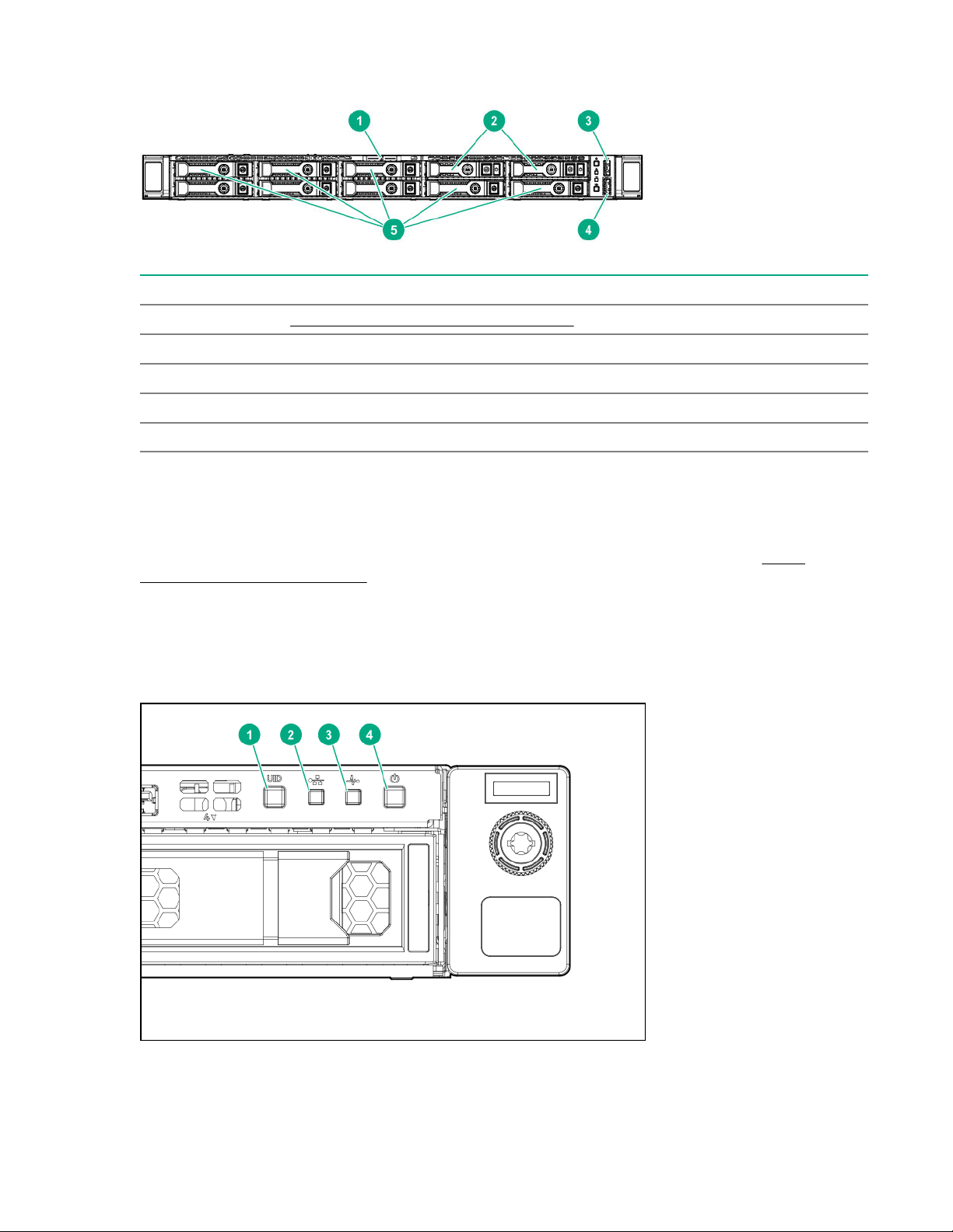
Eight-bay SFF drive model with two-bay SFF drive backplane option
Item Description
1 Serial number/iLO information pull tab
2 NVMe/SAS/SATA drives (optional)
3 Front USB 3.0 port
4 iLO Service Port
5 SFF SmartDrives
Serial number/iLO information pull tab
The serial number/iLO information pull tab is double-sided. One side shows the server serial number and
the QR code labels. The other side shows the default iLO account information.
Use a mobile device to scan the QR code label to display the server mobile product page (http://
www.hpe.com/qref/dl160gen10). This page contains links to server setup information, spare part
numbers, QuickSpecs, troubleshooting resources, and other useful product links.
Front panel LEDs and buttons
Four-bay LFF drive model
Component identification 9
Page 10

Item Description Status
1 UID button/LED
Solid blue = Activated
Flashing blue:
• 1 flash per second = Remote management or
firmware upgrade in progress
• 4 flashes per second = iLO manual reboot sequence
initiated
• 8 flashes per second = iLO manual reboot sequence
in progress
Off = Deactivated
2 NIC status LED
3 Health LED
4 Power On/Standby button and
system power LED
Solid green = Link to network
Flashing green (1 flash per second) = Network active
Off = No network activity
Solid green = Normal
Flashing green (1 flash per second) = iLO is rebooting
Flashing amber = System degraded
Flashing red (1 flash per second) = System critical
If the health LED indicates a degraded or critical state,
review the system IML or use iLO to review the system
health status.
Solid green = System on
Flashing green (1 flash per second) = Performing power
on sequence
Solid amber = System in standby Off = No power
present
If the system power LED is off, verify the following
conditions:
• The facility power is present.
When all four LEDs described in this table flash simultaneously, a power fault has occurred. For more
information, see Power fault LEDs on page 12.
10 Component identification
• The power supply is installed and is working
correctly.
• The power cord is attached and is connected to a
power source.
• The front I/O cable is connected.
Page 11

Eight-bay SFF model
Item Description Status
1 UID button/LED
Solid blue = Activated
Flashing blue:
2 NIC status LED
• 1 flash per second = Remote management or
firmware upgrade in progress
• 4 flashes per second = iLO manual reboot sequence
initiated
• 8 flashes per second = iLO manual reboot sequence
in progress
Off = Deactivated
Solid green = Link to network
Flashing green (1 flash per second) = Network active
Off = No network activity
Table Continued
Component identification 11
Page 12

Item Description Status
3 Health LED
Solid green = Normal
Flashing green (1 flash per second) = iLO is rebooting
Flashing amber = System degraded
Flashing red (1 flash per second) = System critical
If the health LED indicates a degraded or critical state,
review the system IML or use iLO to review the system
health status.
4 Power On/Standby button and
system power LED
When all four LEDs described in this table flash simultaneously, a power fault has occurred. For more
information, see Power fault LEDs on page 12.
Power fault LEDs
The following table provides a list of power fault LEDs, and the subsystems that are affected. Not all
power faults are used by all servers.
Solid green = System on
Flashing green (1 flash per second) = Performing power
on sequence
Solid amber = System in standby Off = No power
present
If the system power LED is off, verify the following
conditions:
• The facility power is present.
• The power supply is installed and is working
correctly.
• The power cord is attached and is connected to a
power source.
• The front I/O cable is connected.
Subsystem LED behavior
System board 1 flash
Processor 2 flashes
Memory 3 flashes
Riser board PCIe slots 4 flashes
FlexibleLOM 5 flashes
Removable HPE Flexible Smart Array
controller
System board PCIe slots 7 flashes
Power backplane or storage backplane 8 flashes
Power supply 9 flashes
12 Component identification
6 flashes
Page 13
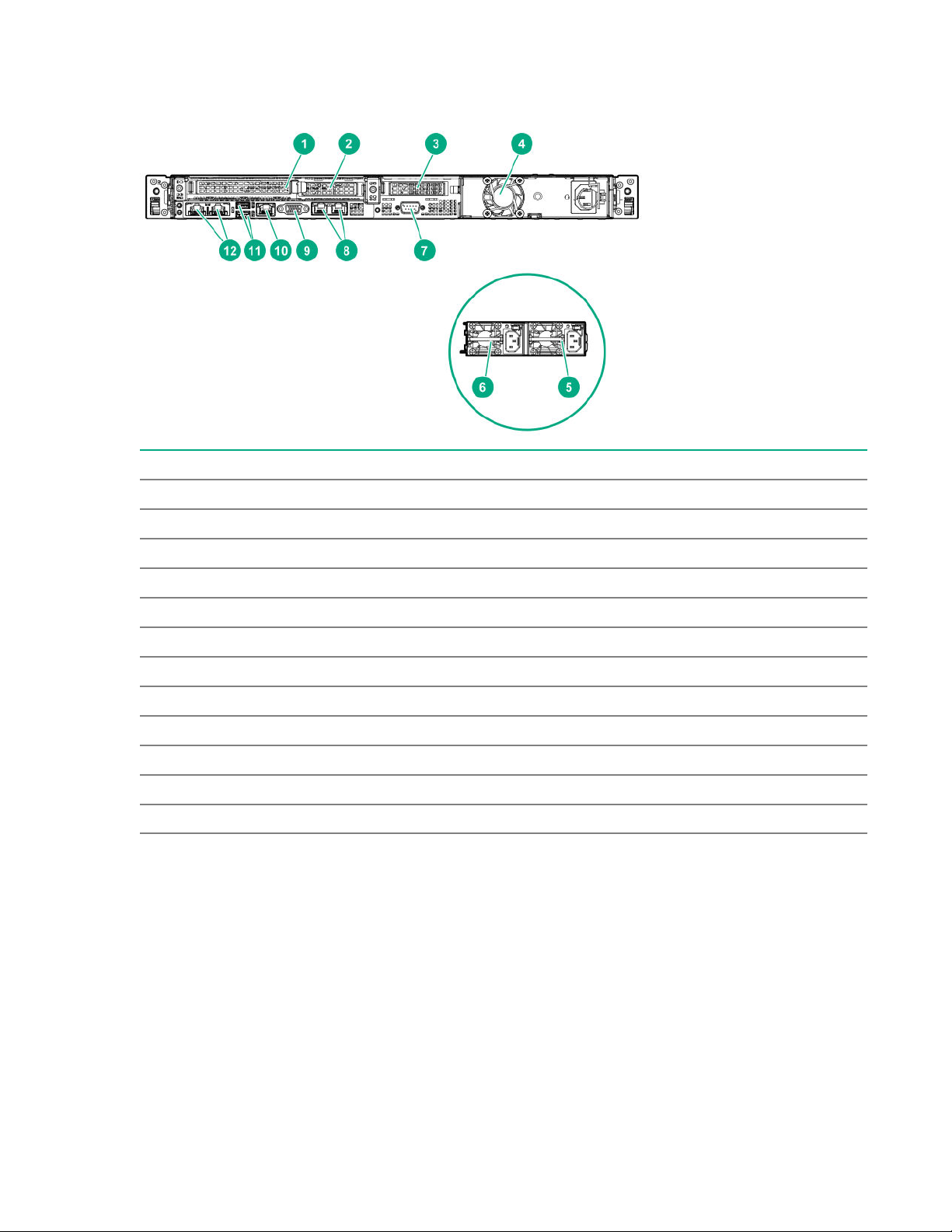
Rear panel components
Item Description
1 PCIe slot 1 or FlexibleLOM
2 PCIe slot 2
3 PCIe slot 3 (secondary riser for processor 2, optional)
4 Standard power supply (non-hot-plug)
5 Flexible Slot power supply 1 (hot-plug)
6 Flexible Slot power supply 2 (hot-plug)
7 Serial port (optional)
8 NIC ports 1-2 (1Gb)
9 VGA port
10 iLO Management Port
11 USB 3.0 ports
12 Media Module (optional NIC ports 3-4)
Component identification 13
Page 14
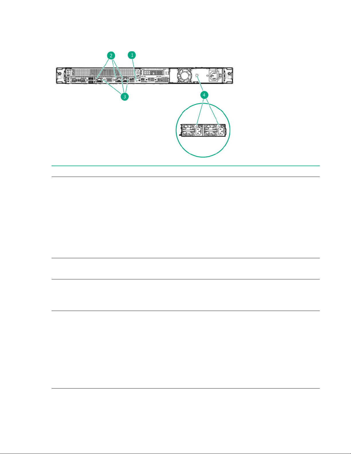
Rear panel LEDs
Item Description Status
1 UID LED
Solid blue = Activated Flashing blue:
• 1 flash per second = Remote management or
firmware upgrade in progress
2 NIC link LED
3 NIC status LED
4 Power supply LED
• 4 flashes per second = iLO manual reboot
sequence initiated
• 8 flashes per second = iLO manual reboot
sequence in progress
• Off = Deactivated
Solid green = Link exits
Off = No network link
Solid green = Link to network
Flashing green = Network active
Off = No network activity
Solid green = Normal
Off = One or more of the following conditions
exists:
• Power is unavailable
• Power supply failed
• Power supply is in standby mode
14 Component identification
• Power supply error
Page 15
PCIe expansion slot definitions
Slot Type Form factor Connector link
width
1
2
3
PCIe 3.0
FlexibleLOM
HL, FH
FlexibleLOM
PCIe 3.0 HL, HH
PCIe 3.0 HL, HH
1
x16
x8
3
3
x8 8, 4, 1
x16 16, 8, 4, 1
Negotiable link
width
16, 8, 4, 1
Supported
expansion
board
Four-port 1 GB
NIC card
2
M.2 SSD
enablement
board
Ethernet NIC
cards (10 GB or
higher)
4
Smart Array PCIe
plug-in controller
M.2 SSD
enablement
board
Four-port 1 GB
NIC card
2
Ethernet NIC
cards (10 GB or
higher)
4
1
HL, FH=Half length, full height
2
This server supports a maximum of two four-port 1 GB NIC cards.
3
HL, HH=Half length, half height
4
This server supports only one Ethernet NIC card.
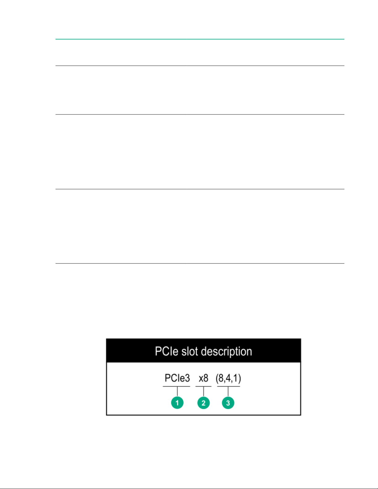
PCIe slot description
M.2 SSD
enablement
board
Component identification 15
Page 16

Item Description Definition
1 PCI Express version Each PCIe version corresponds to a specific data
transfer rate between the processor and peripheral
devices. Generally, a version update corresponds to an
increase in transfer rate.
• PCIe 1.x
• PCIe 2.x
• PCIe 3.x
The PCIe technology is under constant development.
For the latest information, see the PCI-SIG website.
2 Physical connector link width
3 Negotiable link width These numbers correspond to the maximum link
PCIe devices communicate through a logical
connection called an interconnect or link. At the
physical level, a link is composed of one or more lanes.
The number of lanes is written with an "×" prefix with
×16 being the largest size in common use.
• ×1
• ×2
• ×4
• ×8
• ×16
bandwidth supported by the slot.
16 Component identification
Page 17
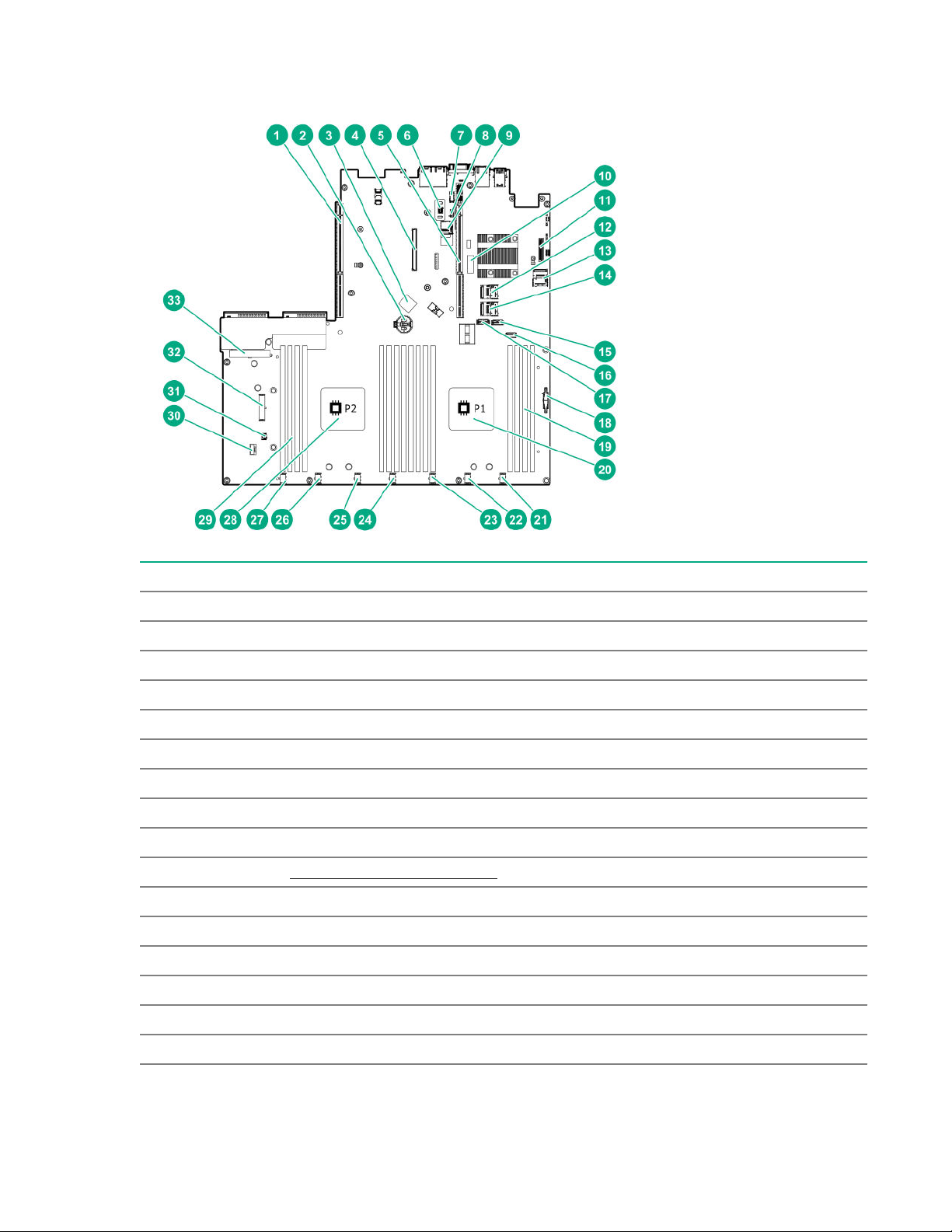
System board components
Item Description
1 Secondary PCIe riser connector for processor 2
2 System battery
3 Internal USB 3.0 port
4 Smart Array modular controller connector
5 Primary PCIe riser connector for processor 1
6 TPM connector
7 Serial port connector
8 iLO Service Port connector
9 microSD card slot
10 System maintenance switch
11 Media Module connector
12 Mini SAS Port 1
13 Mini SAS Port 2
14 Mini SAS Port 3
15 SATA Port 4
1
16 Front USB 3.0 connector
Table Continued
Component identification 17
Page 18

Item Description
17 SATA Port 5
18 Front I/O cable connector
19 DIMM slots for processor 1
20 Processor 1
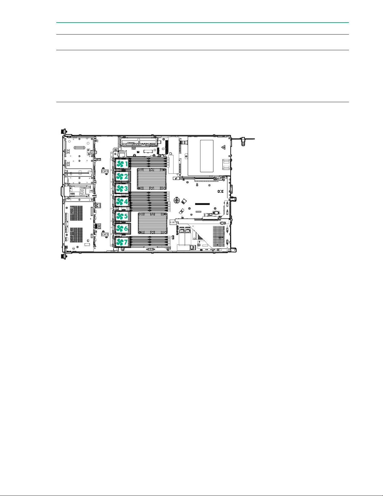
21 Fan connector 7
22 Fan connector 6
23 Fan connector 5
24 Fan connector 4
25 Fan connector 3
26 Fan connector 2
27 Fan connector 1
28 Processor 2
29 DIMM slots for processor 2
30 Smart Storage Battery connector
31 Chassis Intrusion Detection connector
32 Drive backplane power connector
33 Non-hot-plug power supply connector
1
If the memory card connected to the microSD slot is not visible in Windows Device Manager, in the menu bar, click
View > Show hidden device.
System maintenance switch descriptions
Position Default Function
1
S1
S2 Off Reserved
S3 Off Reserved
S4 Off Reserved
1
S5
S61, 2,
Off
Off = iLO security is enabled.
On = iLO security is disabled.
Off
Off = Power-on password is enabled.
On = Power-on password is disabled.
3
Off
Off = No function
On = Restore default manufacturing settings
S7 Off Reserved
S8 — Reserved
18 Component identification
Table Continued
Page 19
Position Default Function
S9 — Reserved
S10 — Reserved
S11 — Reserved
S12 — Reserved
1
To access the redundant ROM, set S1, S5, and S6 to On.
2
When the system maintenance switch position 6 is set to the On position, the system is prepared to restore all
configuration settings to their manufacturing defaults.
3
When the system maintenance switch position 6 is set to the On position and Secure Boot is enabled, some
configurations cannot be restored. For more information, see Secure Boot on page 119.
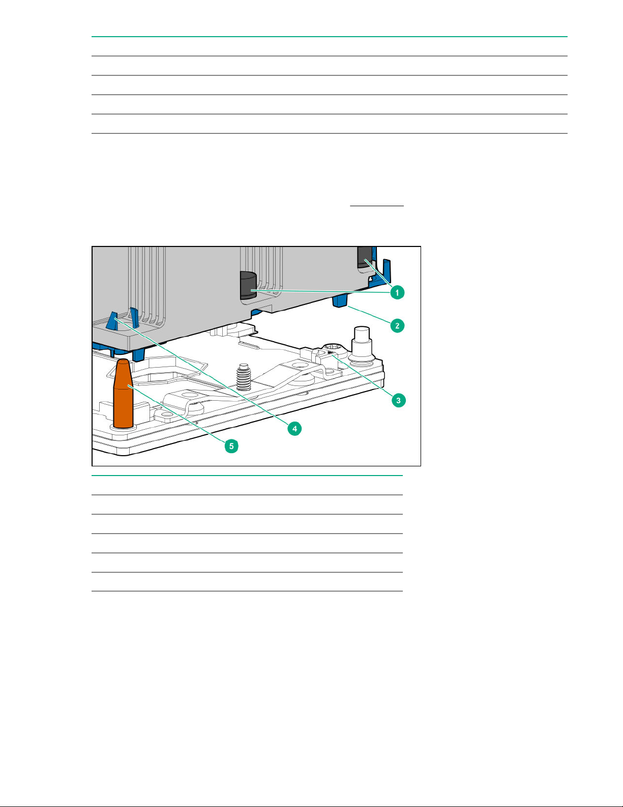
Processor, heatsink, and socket components
Item Description
1 Heatsink nuts
2 Processor carrier
3 Pin 1 indicator
1
4 Heatsink latch
5 Alignment post
1
Symbol also on the processor and frame.
Component identification 19
Page 20
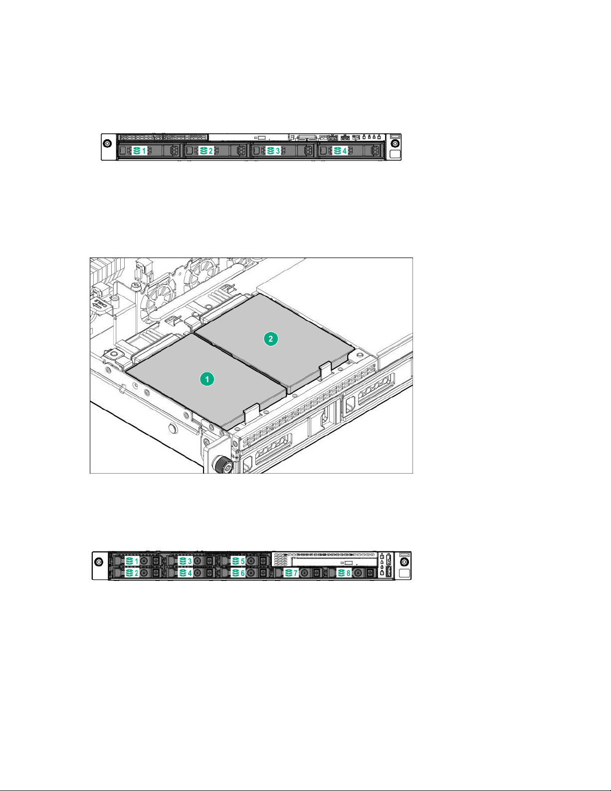
Drive bay numbering
Four-bay LFF drive model
Slim SSD numbering (Four-bay LFF drive model only)
The server detects Slim SSDs as being installed in Box 0.
Eight-bay SFF drive model with optical drive
20 Component identification
Page 21
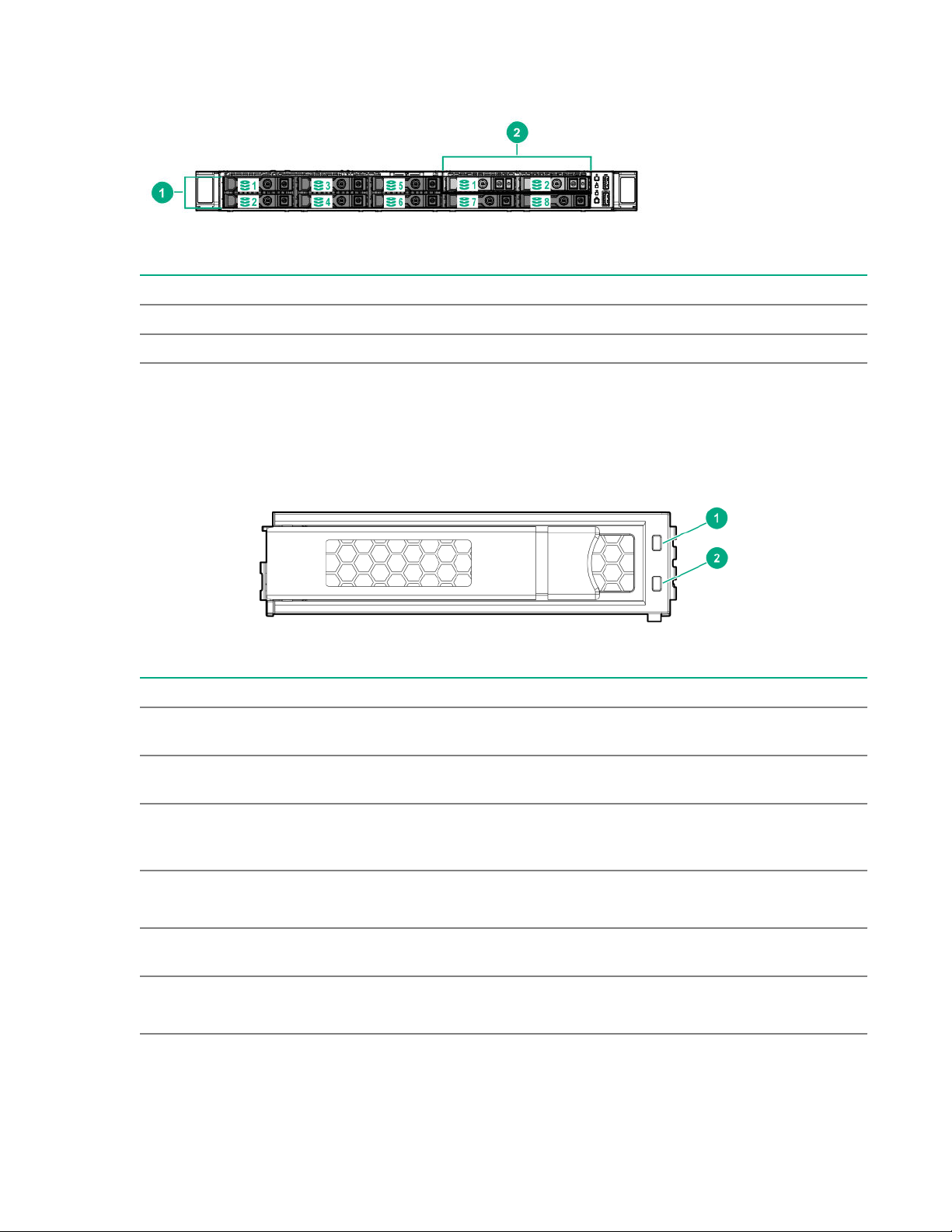
Eight-bay SFF drive model with two-bay SFF drive backplane option
Item Description
1 Box 1
2 Box 2
Drive LEDs and buttons
Low profile LFF drive LED definitions
Item LED Status Definition
1 Fault
\Locate
2 Online
\Activity
Solid amber The drive has failed.
Solid blue The drive is operating normally and being identified by a
management application.
Flashing amber/blue
(1 flash per second)
Flashing amber
(1 flash per second)
Solid green The drive is online and has no activity.
Flashing green
(4 flashes per second)
The drive has failed, or a predictive failure alert has been
received for this drive; it also has been identified by a
management application.
A predictive failure alert has been received for this drive.
Replace the drive as soon as possible.
The drive is operating normally and has activity.
Table Continued
Component identification 21
Page 22
Item LED Status Definition
Flashing green
(1 flash per second)
Off The drive is not configured by a RAID controller or a spare
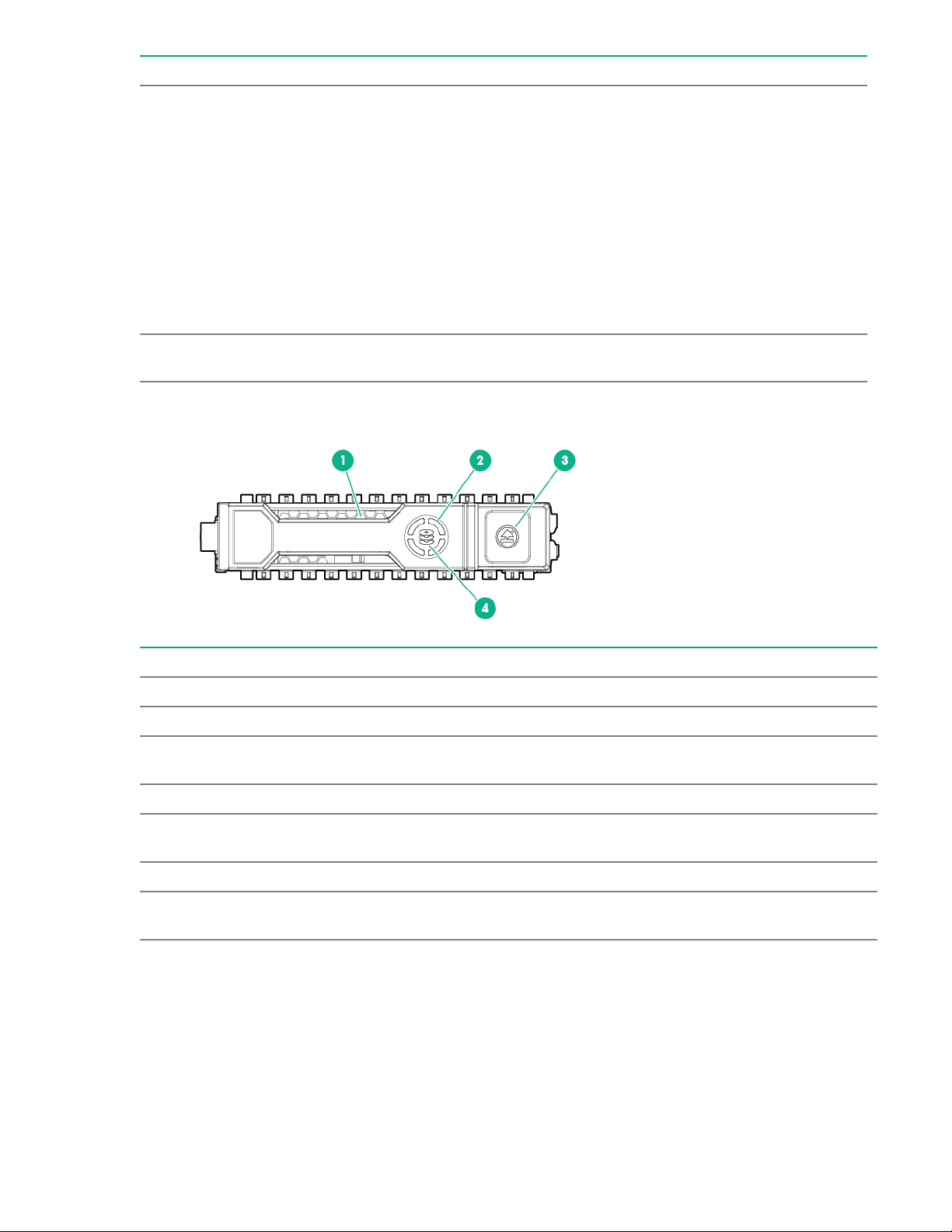
Hot-plug drive LED definitions
The drive is doing one of the following:
• Rebuilding
• Performing a RAID migration
• Performing a strip size migration
• Performing a capacity expansion
• Performing a logical drive extension
• Erasing
• Spare part activation
drive.
Item LED Status Definition
1 Locate Solid blue The drive is being identified by a host application.
Flashing blue The drive carrier firmware is being updated or requires an update.
2 Activity
ring
Off No drive activity
3 Do not
remove
Off Removing the drive does not cause a logical drive to fail.
4 Drive
status
Rotating green Drive activity
Solid white Do not remove the drive. Removing the drive causes one or more of
the logical drives to fail.
Solid green The drive is a member of one or more logical drives.
Table Continued
22 Component identification
Page 23
Item LED Status Definition
Flashing green
The drive is doing one of the following:
• Rebuilding
• Performing a RAID migration
• Performing a strip size migration
• Performing a capacity expansion
• Performing a logical drive extension
• Erasing
• Spare part activation
Flashing amber/
green
Flashing amber The drive is not configured and predicts the drive will fail.
Solid amber The drive has failed.
Off The drive is not configured by a RAID controller or a spare drive.
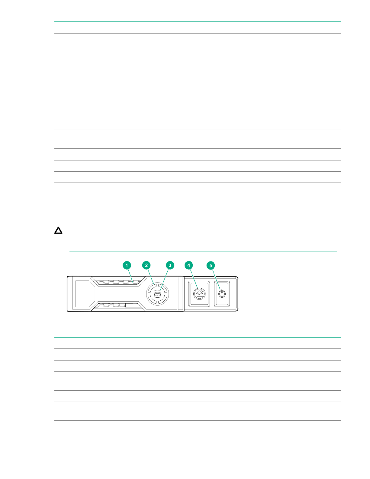
NVMe SSD LED definitions
The NVMe SSD is a PCIe bus device. A device attached to a PCIe bus cannot be removed without
allowing the device and bus to complete and cease the signal/traffic flow.
CAUTION: Do not remove an NVMe SSD from the drive bay while the Do not remove LED is
flashing. The Do not remove LED flashes to indicate that the device is still in use. Removing the
NVMe SSD before the device has completed and ceased signal/traffic flow can cause loss of data.
The drive is a member of one or more logical drives and predicts the
drive will fail.
Item LED Status Definition
1 Locate Solid blue The drive is being identified by a host application.
Flashing blue The drive carrier firmware is being updated or requires an update.
2 Activity
ring
Off No drive activity
3 Drive
status
Rotating green Drive activity
Solid green The drive is a member of one or more logical drives.
Table Continued
Component identification 23
Page 24
Item LED Status Definition
Flashing green
The drive is doing one of the following:
• Rebuilding
• Performing a RAID migration
• Performing a stripe size migration
• Performing a capacity expansion
• Performing a logical drive extension
• Erasing
Flashing amber/
green
Flashing amber The drive is not configured and predicts the drive will fail.
Solid amber The drive has failed.
Off The drive is not configured by a RAID controller.
4 Do not
remove
Flashing white The drive ejection request is pending.
5 Power Solid green Do not remove the drive. The drive must be ejected from the PCIe bus
Solid white Do not remove the drive. The drive must be ejected from the PCIe bus
Off The drive has been ejected.
Flashing green The drive ejection request is pending.
Off The drive has been ejected.
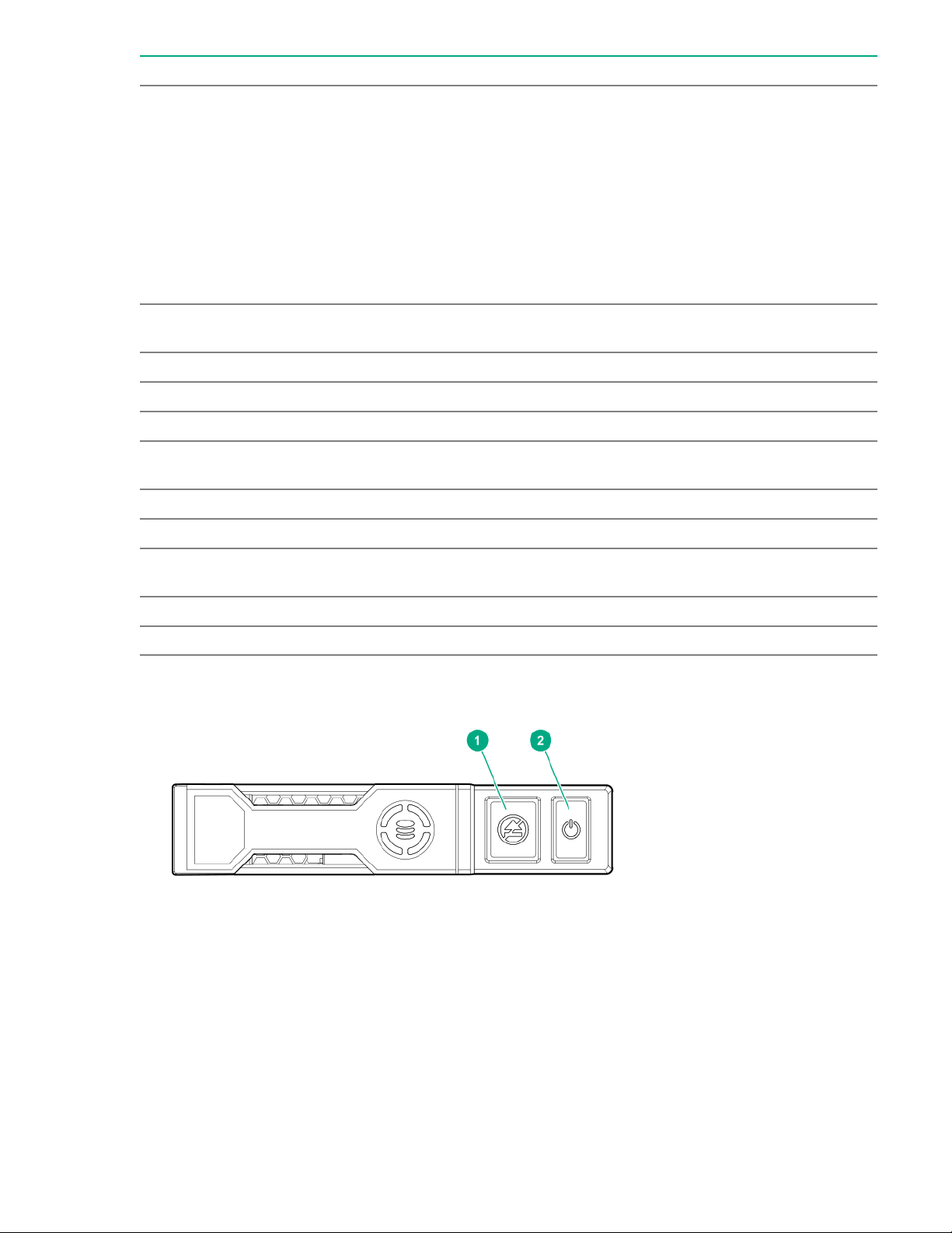
NVMe SSD button actions
The drive is a member of one or more logical drives and predicts the
drive will fail.
prior to removal.
prior to removal.
24 Component identification
Page 25
Item Button Action
1 Do Not Remove
2 Power
Fan locations
Press to open the release lever.
Press to request PCIe ejection. Removal request can be denied
by the:
• RAID controller (one or more of the logical drives could fail)
• Operating system
Component identification 25
Page 26

Setup
Optional service
Delivered by experienced, certified engineers, Hewlett Packard Enterprise support services help you keep
your servers up and running with support packages tailored specifically for HPE ProLiant systems.
Hewlett Packard Enterprise support services let you integrate both hardware and software support into a
single package. A number of service level options are available to meet your business and IT needs.
Hewlett Packard Enterprise support services offer upgraded service levels to expand the standard
product warranty with easy-to-buy, easy-to-use support packages that will help you make the most of your
server investments. Some of the Hewlett Packard Enterprise support services for hardware, software or
both are:
• Foundation Care – Keep systems running.
◦ 6-Hour Call-to-Repair
◦ 4-Hour 24x7
◦ Next Business Day
• Proactive Care – Help prevent service incidents and get you to technical experts when there is one.
◦ 6-Hour Call-to-Repair
1
1
◦ 4-Hour 24x7
◦ Next Business Day
• Deployment service for both hardware and software
• Hewlett Packard Enterprise Education Services – Help train your IT staff.
1
The time commitment for this repair service might vary depending on the site's geographical region. For
more service information available in your site, contact your local
center.
For more information on Hewlett Packard Enterprise support services, see the Hewlett Packard
Enterprise website.
Initial server installation
Depending on the user technical expertise and the complexity of the product, for the initial server
installation, the user can choose to:
• Order the HPE Installation Service.
• Perform the initial server setup procedure.
HPE Installation Service
Hewlett Packard Enterprise support
HPE Installation Service provides basic installation of Hewlett Packard Enterprise branded equipment,
software products, as well as HPE-supported products from other vendors that are sold by HPE or by
HPE authorized resellers. The Installation Service is part of a suite of HPE deployment services that are
designed to give users the peace of mind that comes from knowing that their HPE and HPE-supported
products have been installed by an HPE specialist.
The HPE Installation Service provides the following benefits:
26 Setup
Page 27

• Installation by an HPE authorized technical specialist.
• Verification prior to installation that all service prerequisites are met.
• Delivery of the service at a mutually scheduled time convenient to your organization.
• Allows your IT resources to stay focused on their core tasks and priorities.
• Full coverage during the warranty period for products that require installation by an HPE authorized
technical specialist.
For more information on the features, limitations, provisions, and ordering information of the HPE
Installation Service, see this Hewlett Packard Enterprise website:
http://www.hpe.com/support/installation-service
Setting up the server
Prerequisites
Before setting up the server:
• Download the latest SPP:
http://www.hpe.com/servers/spp/download
Support validation required
• Verify that your OS or virtualization software is supported:
http://www.hpe.com/info/ossupport
• Read the HPE UEFI requirements for ProLiant servers on the Hewlett Packard Enterprise website.
If UEFI requirements are not met, you might experience boot failures or other errors when installing
the operating system.
• Read the operational requirements for the server:
Operational requirements on page 30
• Obtain the storage driver if needed:
◦ Download it from the HPE support center website:
http://www.hpe.com/support/hpesc
◦ Extract it from the SPP.
• Read the safety and compliance information on the HPE website:
http://www.hpe.com/support/safety-compliance-enterpriseproducts
Procedure
Unbox the server
1. Unbox the server and verify the contents:
• Server
• Power cord
Setup 27
Page 28

• Rack-mounting hardware (optional)
• Documentation
The server does not ship with OS media. All system software and firmware is preloaded on the server.
Install the hardware options
2. (Optional) Install hardware options. For installation instructions, see Hardware options installation
on page 49.
Rack the server
3. Install the server in a rack.
4. Decide how to manage the server:
• Locally: use a KVM switch or a connect a keyboard, monitor, and mouse.
• Remotely: connect to the iLO web interface and run a remote console:
a. Verify the following:
◦ iLO is licensed to use the remote console feature.
If iLO is not licensed, visit the HPE website:
http://www.hpe.com/info/ilo
◦ The iLO management port is connected to a secure network.
b. Using a browser, navigate to the iLO web interface, and then log in.
https://<iLO hostname or IP address>
Note the following:
◦ The iLO hostname is located on the serial pull tab.
◦ If a DHCP server assigns the IP address, the IP address appears on the boot screen.
◦ If a static IP address is assigned, use that IP address.
◦ The default login credentials are located on the serial label pull tab.
c. In the side navigation, click the Remote Console & Media link, and then launch a remote
console.
Power on the server
5. Press the Power On/Standby button.
For remote management, use the iLO virtual power button.
Update the firmware
6. Using the SPP, update the following:
• System ROM
28 Setup
• Storage controller
• Network adapters
• Intelligent Provisioning
Page 29

Set up storage
7. Do one of the following:
• To configure the server to boot from a SAN, see the following guide:
https://www.hpe.com/info/boot-from-san-config-guide
• If an HPE Smart Array SR controller is installed, use HPE Smart Storage Administrator to create
arrays:
a. From the boot screen, press F10 to run Intelligent Provisioning.
b. From Intelligent Provisioning, run HPE Smart Storage Administrator.
• If no controller is installed, do one of the following:
◦ AHCI is enabled by default. You can deploy an OS or virtualization software.
◦ Disable AHCI, enable software RAID, and then create an array:
a. From the boot screen, press F9 to run UEFI System Utilities.
b. From the UEFI System Utilities screen, select System Configurations > BIOS/Platform
Configuration (RBSU) > Storage Options > SATA Controller Options > Embedded
SATA configuration > Smart Array SW RAID Support
c. Enable SW RAID.
d. Save the configuration and reboot the server.
e. Create an array:
I. From the boot screen, press F9 to run UEFI System Utilities.
II. From the UEFI System Utilities screen, select System Configuration > Embedded
Storage: HPE Smart Storage S100i SR Gen10 > Array Configuration > Create
Array
Deploy an OS or virtualization software
8. Do one of the following:
• Run Intelligent Provisioning to deploy an OS.
Press F10 at the boot screen to run Intelligent Provisioning.
• Manually deploy an OS.
a. Insert the installation media.
For remote management, click Virtual Drives in the iLO remote console to mount images,
drivers, or files to a virtual folder. If a storage driver is required to install the OS, use the virtual
folder to store the driver.
b. Press F11 at the boot screen to select the boot device.
c. After the OS is installed, update the drivers.
Register the server
9. To experience quicker service and more efficient support, register the server at the HPE website:
Setup 29
Page 30
https://myenterpriselicense.hpe.com
Operational requirements
Space and airflow requirements
To allow for servicing and adequate airflow, observe the following space and airflow requirements when
deciding where to install a rack:
• Leave a minimum clearance of 63.5 cm (25 in) in front of the rack.
• Leave a minimum clearance of 76.2 cm (30 in) behind the rack.
• Leave a minimum clearance of 121.9 cm (48 in) from the back of the rack to the back of another rack
or row of racks.
Hewlett Packard Enterprise servers draw in cool air through the front door and expel warm air through the
rear door. Therefore, the front and rear rack doors must be adequately ventilated to allow ambient room
air to enter the cabinet, and the rear door must be adequately ventilated to allow the warm air to escape
from the cabinet.
CAUTION: To prevent improper cooling and damage to the equipment, do not block the ventilation
openings.
When vertical space in the rack is not filled by a server or rack component, the gaps between the
components cause changes in airflow through the rack and across the servers. Cover all gaps with
blanking panels to maintain proper airflow.
CAUTION: Always use blanking panels to fill empty vertical spaces in the rack. This arrangement
ensures proper airflow. Using a rack without blanking panels results in improper cooling that can
lead to thermal damage.
The 9000 and 10000 Series Racks provide proper server cooling from flow-through perforations in the
front and rear doors that provide 64 percent open area for ventilation.
CAUTION: When using a Compaq branded 7000 series rack, install the high airflow rack door insert
(PN 327281-B21 for 42U rack, PN 157847-B21 for 22U rack) to provide proper front-to-back airflow
and cooling.
CAUTION: If a third-party rack is used, observe the following additional requirements to ensure
adequate airflow and to prevent damage to the equipment:
• Front and rear doors—If the 42U rack includes closing front and rear doors, you must allow
5,350 sq cm (830 sq in) of holes evenly distributed from top to bottom to permit adequate airflow
(equivalent to the required 64 percent open area for ventilation).
• Side—The clearance between the installed rack component and the side panels of the rack must
be a minimum of 7 cm (2.75 in).
Temperature requirements
To ensure continued safe and reliable equipment operation, install or position the system in a wellventilated, climate-controlled environment.
30 Setup
Page 31
The maximum recommended ambient operating temperature (TMRA) for most server products is 35°C
(95°F). The temperature in the room where the rack is located must not exceed 35°C (95°F).
CAUTION: To reduce the risk of damage to the equipment when installing third-party options:
• Do not permit optional equipment to impede airflow around the server or to increase the internal
rack temperature beyond the maximum allowable limits.
• Do not exceed the manufacturer’s TMRA.
Power requirements
Installation of this equipment must comply with local and regional electrical regulations governing the
installation of information technology equipment by licensed electricians. This equipment is designed to
operate in installations covered by NFPA 70, 1999 Edition (National Electric Code) and NFPA-75, 1992
(code for Protection of Electronic Computer/Data Processing Equipment). For electrical power ratings on
options, refer to the product rating label or the user documentation supplied with that option.
WARNING: To reduce the risk of personal injury, fire, or damage to the equipment, do not overload
the AC supply branch circuit that provides power to the rack. Consult the electrical authority having
jurisdiction over wiring and installation requirements of your facility.
CAUTION: Protect the server from power fluctuations and temporary interruptions with a regulating
uninterruptible power supply. This device protects the hardware from damage caused by power
surges and voltage spikes and keeps the system in operation during a power failure.
Electrical grounding requirements
The server must be grounded properly for proper operation and safety. In the United States, you must
install the equipment in accordance with NFPA 70, 1999 Edition (National Electric Code), Article 250, as
well as any local and regional building codes. In Canada, you must install the equipment in accordance
with Canadian Standards Association, CSA C22.1, Canadian Electrical Code. In all other countries, you
must install the equipment in accordance with any regional or national electrical wiring codes, such as the
International Electrotechnical Commission (IEC) Code 364, parts 1 through 7. Furthermore, you must be
sure that all power distribution devices used in the installation, such as branch wiring and receptacles, are
listed or certified grounding-type devices.
Because of the high ground-leakage currents associated with multiple servers connected to the same
power source, Hewlett Packard Enterprise recommends the use of a PDU that is either permanently wired
to the building’s branch circuit or includes a nondetachable cord that is wired to an industrial-style plug.
NEMA locking-style plugs or those complying with IEC 60309 are considered suitable for this purpose.
Using common power outlet strips for the server is not recommended.
Setup 31
Page 32
Server warnings and cautions
WARNING: This server is heavy. To reduce the risk of personal injury or damage to the equipment:
• Observe local occupational health and safety requirements and guidelines for manual material
handling.
• Get help to lift and stabilize the product during installation or removal, especially when the
product is not fastened to the rails. Hewlett Packard Enterprise recommends that a minimum of
two people are required for all rack server installations. A third person may be required to help
align the server if the server is installed higher than chest level.
• Use caution when installing the server in or removing the server from the rack; it is unstable
when not fastened to the rails.
WARNING: To reduce the risk of personal injury from hot surfaces, allow the drives and the internal
system components to cool before touching them.
WARNING: To reduce the risk of personal injury, electric shock, or damage to the equipment,
remove the power cord to remove power from the server. Pressing the Power On/Standby button
does not shut off system power completely. Portions of the power supply and some internal circuitry
remain active until AC power is removed.
CAUTION: Protect the server from power fluctuations and temporary interruptions with a regulating
uninterruptible power supply. This device protects the hardware from damage caused by power
surges and voltage spikes and keeps the system in operation during a power failure.
CAUTION: Do not operate the server for long periods with the access panel open or removed.
Operating the server in this manner results in improper airflow and improper cooling that can lead to
thermal damage.
Rack warnings
WARNING: To reduce the risk of personal injury or damage to the equipment, be sure that:
• The leveling jacks are extended to the floor.
• The full weight of the rack rests on the leveling jacks.
• The stabilizing feet are attached to the rack if it is a single-rack installation.
• The racks are coupled together in multiple-rack installations.
• Only one component is extended at a time. A rack may become unstable if more than one
component is extended for any reason.
32 Setup
Page 33
WARNING: To reduce the risk of personal injury or equipment damage when unloading a rack:
• At least two people are needed to safely unload the rack from the pallet. An empty 42U rack can
weigh as much as 115 kg (253 lb), can stand more than 2.1 m (7 ft) tall, and might become
unstable when being moved on its casters.
• Never stand in front of the rack when it is rolling down the ramp from the pallet. Always handle
the rack from both sides.
WARNING: To reduce the risk of personal injury or damage to the equipment, adequately stabilize
the rack before extending a component outside the rack. Extend only one component at a time. A
rack may become unstable if more than one component is extended.
WARNING: When installing a server in a telco rack, be sure that the rack frame is adequately
secured at the top and bottom to the building structure.
Electrostatic discharge
Be aware of the precautions you must follow when setting up the system or handling components. A
discharge of static electricity from a finger or other conductor may damage system boards or other staticsensitive devices. This type of damage may reduce the life expectancy of the system or component.
To prevent electrostatic damage:
• Avoid hand contact by transporting and storing products in static-safe containers.
• Keep electrostatic-sensitive parts in their containers until they arrive at static-free workstations.
• Place parts on a grounded surface before removing them from their containers.
• Avoid touching pins, leads, or circuitry.
• Always be properly grounded when touching a static-sensitive component or assembly. Use one or
more of the following methods when handling or installing electrostatic-sensitive parts:
◦ Use a wrist strap connected by a ground cord to a grounded workstation or computer chassis. Wrist
straps are flexible straps with a minimum of 1 megohm ±10 percent resistance in the ground cords.
To provide proper ground, wear the strap snug against the skin.
◦ Use heel straps, toe straps, or boot straps at standing workstations. Wear the straps on both feet
when standing on conductive floors or dissipating floor mats.
◦ Use conductive field service tools.
◦ Use a portable field service kit with a folding static-dissipating work mat.
If you do not have any of the suggested equipment for proper grounding, have an authorized reseller
install the part.
For more information on static electricity or assistance with product installation, contact an authorized
reseller.
Installing the server into the rack
To install the server into a rack with square, round, or threaded holes, refer to the instructions that ship
with the rack hardware kit.
Setup 33
Page 34
If you are installing the server into a telco rack, order the appropriate option kit at the
RackSolutions.com website. To install the rack brackets, follow the server-specific instructions on the
website.
WARNING: This server is heavy. To reduce the risk of personal injury or damage to the equipment:
• Observe local occupational health and safety requirements and guidelines for manual material
handling.
• Get help to lift and stabilize the product during installation or removal, especially when the
product is not fastened to the rails. Hewlett Packard Enterprise recommends that a minimum of
two people are required for all rack server installations. A third person may be required to help
align the server if the server is installed higher than chest level.
• Use caution when installing the server in or removing the server from the rack; it is unstable
when not fastened to the rails.
CAUTION: Always plan the rack installation so that the heaviest item is on the bottom of the rack.
Install the heaviest item first, and continue to populate the rack from the bottom to the top.
Procedure
1. Install the server and cable management arm into the rack. For more information, see the installation
instructions that ship with the selected rail system.
2. Connect peripheral devices to the server. For more information, see Rear panel components.
3. Connect the power cord to the rear of the server.
4. Use the hook-and-loop strap to secure the power cord.
5. Connect the power cord to the power source.
POST screen options
When the server is powered on, the POST screen is displayed. The following options are displayed:
• System Utilities (F9)
Use this option to configure the system BIOS.
• Intelligent Provisioning (F10)
Use this option to deploy an operating system or configure storage.
• Boot order (F11)
Use this option to make a one-time boot selection.
• Network boot (F12)
Use this option to boot the server from the network.
Operating system
This ProLiant server does not ship with provisioning media. Everything required to manage and install the
system software and firmware is preloaded on the server.
To operate properly, the server must have a supported operating system. Attempting to run an
unsupported operating system can cause serious and unpredictable results. For the latest information on
operating system support, see the Hewlett Packard Enterprise website.
34 Setup
Page 35

Failure to observe UEFI requirements for ProLiant Gen10 servers can result in errors installing the
operating system, failure to recognize boot media, and other boot failures. For more information on these
requirements, see the HPE UEFI Requirements on the Hewlett Packard Enterprise website.
To install an operating system on the server, use one of the following methods:
• Intelligent Provisioning—For single-server deployment, updating, and provisioning capabilities. For
more information, see Installing the operating system with Intelligent Provisioning on page 35.
• Insight Control server provisioning—For multiserver remote OS deployment, use Insight Control server
provisioning for an automated solution. For more information, see the Insight Control documentation
on the Hewlett Packard Enterprise website.
For additional system software and firmware updates, download the Service Pack for ProLiant from the
Hewlett Packard Enterprise website. Software and firmware must be updated before using the server
for the first time, unless any installed software or components require an older version.
For more information, see Keeping the system current on page 121.
For more information on using these installation methods, see the Hewlett Packard Enterprise website.
Installing the operating system with Intelligent Provisioning
Procedure
1. Connect the Ethernet cable between the network connector on the server and a network jack.
2. Press the Power On/Standby button.
3. During server POST, press F10.
4. Complete the initial Preferences and Registration portion of Intelligent Provisioning.
5. At the 1 Start screen, click Configure and Install.
6. To finish the installation, follow the onscreen prompts. An Internet connection is required to update the
firmware and systems software.
Installing or deploying an operating system
Before installing an operating system, observe the following:
• Be sure to read the HPE UEFI requirements for ProLiant servers on the Hewlett Packard Enterprise
website. If UEFI requirements are not met, you might experience boot failures or other errors when
installing the operating system.
• Update firmware before using the server for the first time, unless software or components require an
older version. For more information, see "Keeping the system current on page 121."
• For the latest information on supported operating systems, see the Hewlett Packard Enterprise
website.
• The server does not ship with OS media. All system software and firmware is preloaded on the server.
Setup 35
Page 36

Operations
Power up the server
To power up the server, use one of the following methods:
• Press the Power On/Standby button.
• Use the virtual power button through iLO.
Powering down the server
Before powering down the server for any upgrade or maintenance procedures, perform a backup of
critical server data and programs.
IMPORTANT: When the server is in standby mode, auxiliary power is still being provided to the
system.
To power down the server, use one of the following methods:
• Press and release the Power On/Standby button.
This method initiates a controlled shutdown of applications and the OS before the server enters
standby mode.
• Press and hold the Power On/Standby button for more than 4 seconds to force the server to enter
standby mode.
This method forces the server to enter standby mode without properly exiting applications and the OS.
If an application stops responding, you can use this method to force a shutdown.
• Use a virtual power button selection through iLO.
This method initiates a controlled remote shutdown of applications and the OS before the server
enters standby mode.
Before proceeding, verify that the server is in standby mode by observing that the system power LED is
amber.
Extend the server from the rack
NOTE: If the optional cable management arm option is installed, you can extend the server without
powering down the server or disconnecting peripheral cables and power cords. These steps are only
necessary with the standard cable management solution.
Procedure
1. Power down the server (Powering down the server on page 36).
2. Disconnect all peripheral cables and power cords.
3. Loosen the front panel thumbscrews.
4. Extend the server on the rack rails until the server rail-release latches engage.
36 Operations
Page 37
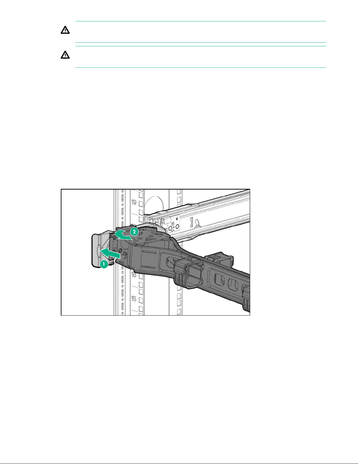
WARNING: To reduce the risk of personal injury or equipment damage, be sure that the rack is
adequately stabilized before extending a component from the rack.
WARNING: To reduce the risk of personal injury, be careful when pressing the server rail-release
latches and sliding the server into the rack. The sliding rails could pinch your fingers.
5. After performing the installation or maintenance procedure, slide the server into the rack:
a. Slide the server fully into the rack.
b. Secure the server by tightening the thumbscrews.
6. Connect the peripheral cables and power cords.
Access the product rear panel
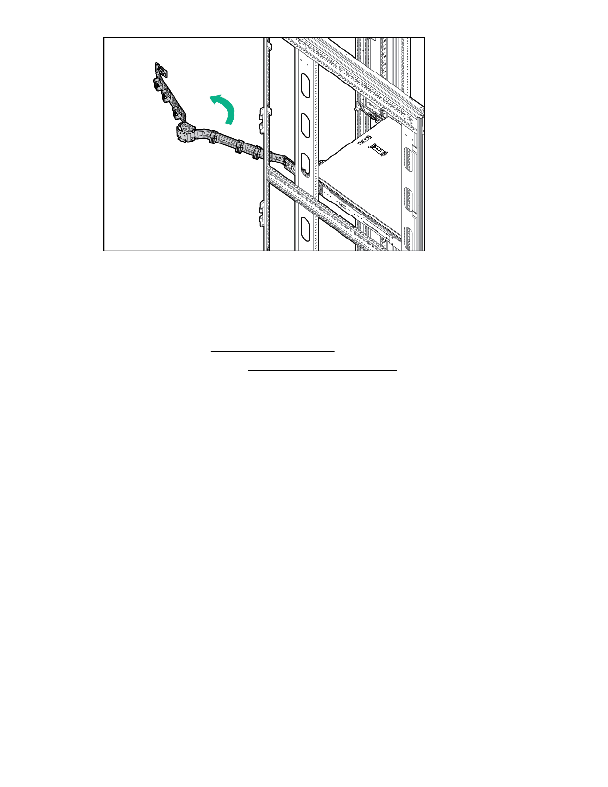
Opening the cable management arm
To access the server rear panel:
1. Release the cable management arm.
2. Open the cable management arm. The cable management arm can be right-mounted or left-mounted.
Operations 37
Page 38
Remove the server from the rack
To remove the server from a Hewlett Packard Enterprise, Compaq-branded, Telco, or third-party rack:
Procedure
1. Power down the server (Powering down the server on page 36).
2. Extend the server from the rack (Extend the server from the rack on page 36).
3. Disconnect the cabling and remove the server from the rack. For more information, see the
documentation that ships with the rack mounting option.
4. Place the server on a sturdy, level surface.
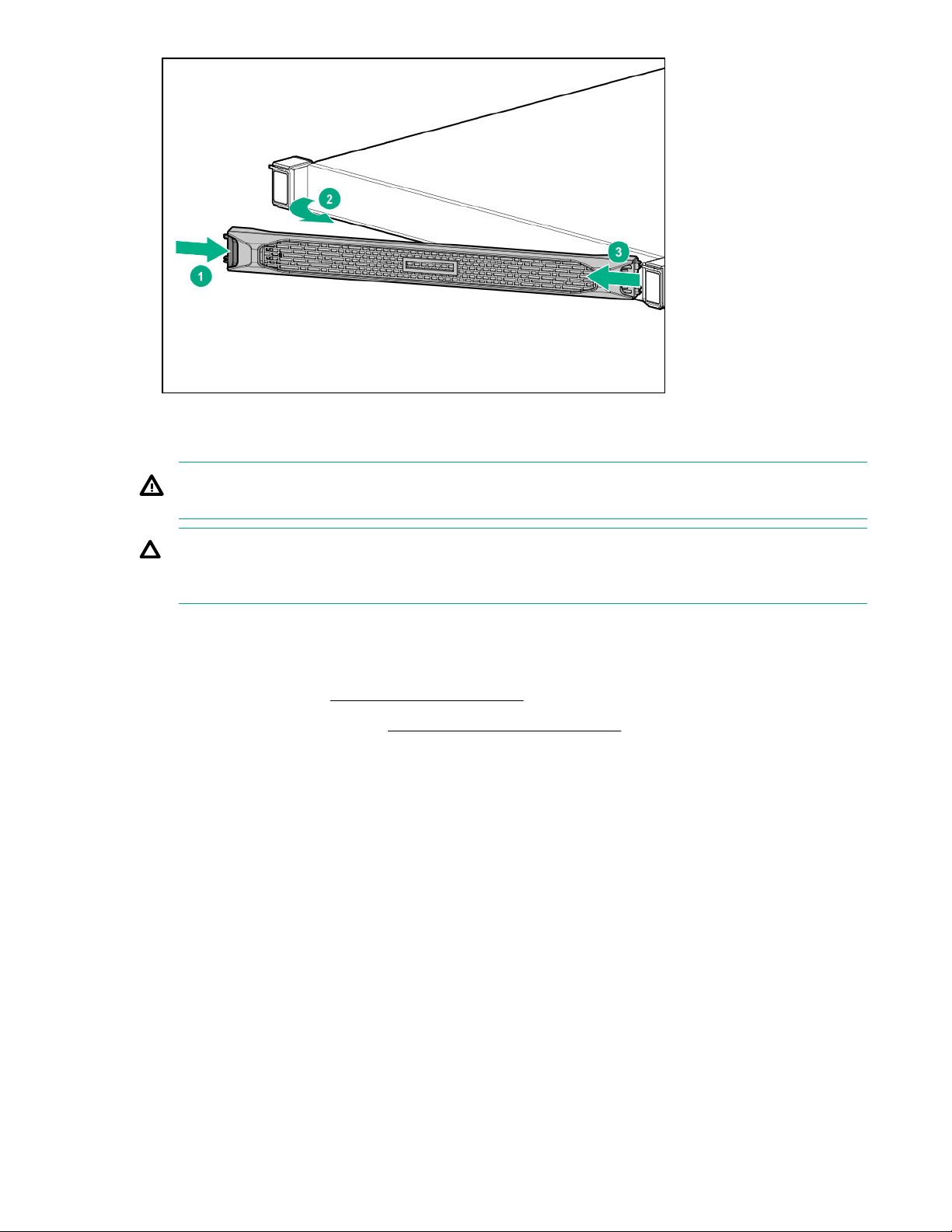
Removing the front bezel
Procedure
1. If installed, unlock and remove the Kensington security lock.
For more information, see the lock documentation.
2. Remove the front bezel.
38 Operations
Page 39
Remove the access panel
WARNING: To reduce the risk of personal injury from hot surfaces, allow the drives and the internal
system components to cool before touching them.
CAUTION: Do not operate the server for long periods with the access panel open or removed.
Operating the server in this manner results in improper airflow and improper cooling that can lead to
thermal damage.
To remove the component:
Procedure
1. Power down the server (Powering down the server on page 36).
2. Extend the server from the rack (Extend the server from the rack on page 36).
3. Open or unlock the locking latch, slide the access panel to the rear of the chassis, and remove the
access panel.
Installing the access panel
Procedure
1. Place the access panel on top of the server with the latch open.
Allow the panel to extend past the rear of the server approximately 1.25 cm (0.5 in).
2. Push down on the latch.
The access panel slides to a closed position.
3. Tighten the security screw on the latch, if needed.
Operations 39
Page 40
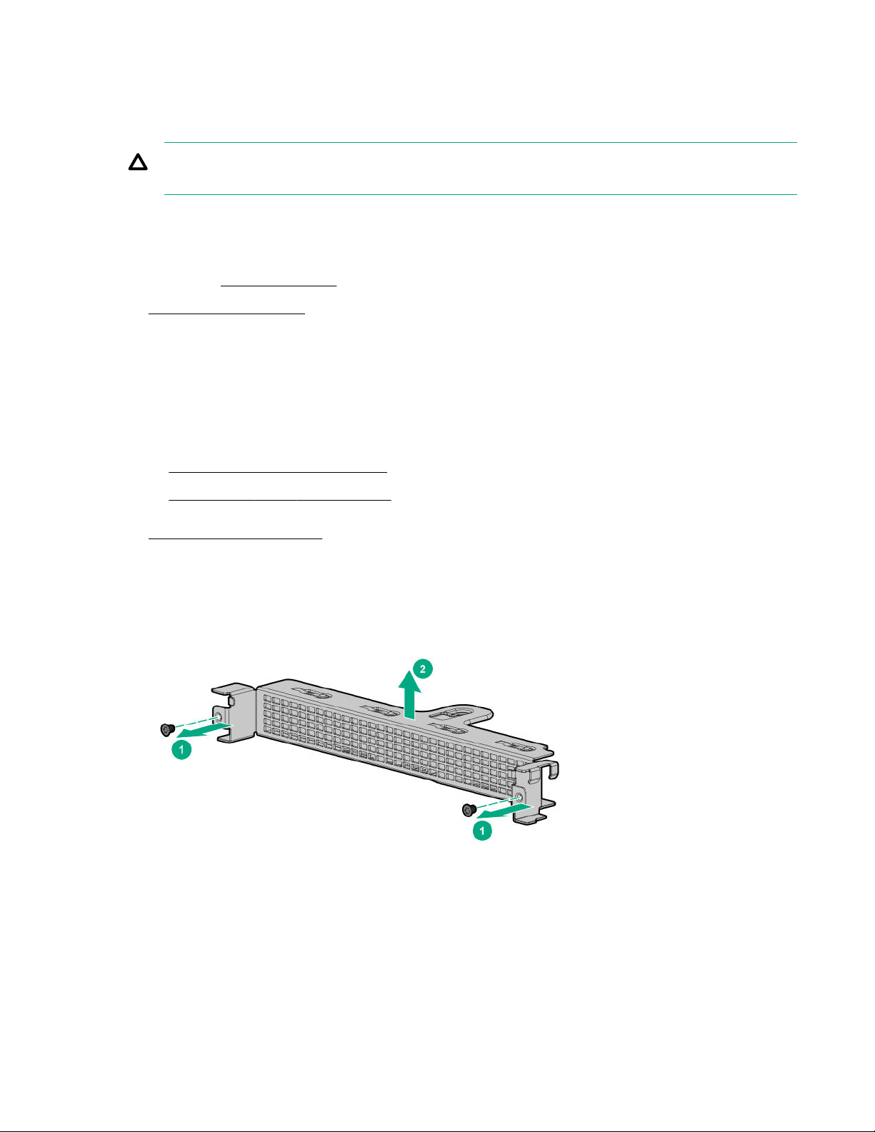
Removing the primary PCI riser blank
Prerequisites
Before you perform this procedure, make sure that you have a T-10 Torx screwdriver available.
CAUTION: To prevent improper cooling and thermal damage, do not operate the server unless all
bays are populated with either a component or a blank.
Procedure
1. Back up all server data.
2. If installed, remove the bezel.
3. Power down the server.
4. Remove all power:
a. Disconnect each power cord from the power source.
b. Disconnect each power cord from the server.
5. Do one of the following:
• Extend the server from the rack..
• Remove the server from the rack.
6. Remove the access panel.
7. Remove the primary PCI riser blank:
Installing the primary PCI riser blank
Prerequisites
Before you perform this procedure, make sure that you have a T-10 Torx screwdriver available.
40 Operations
Page 41
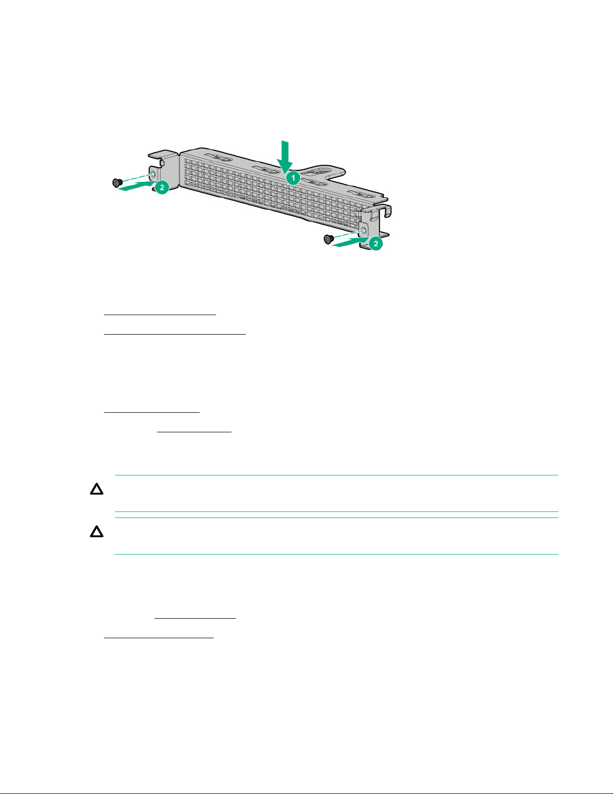
Procedure
1. Install the primary PCI riser blank.
2. Install the access panel.
3. Install the server into the rack.
4. Connect all peripheral cables to the server.
5. Connect each power cord to the server.
6. Connect each power cord to the power source.
7. Power up the server.
8. If removed, install the bezel.
Removing the primary PCI riser cage
CAUTION: To prevent damage to the server or expansion boards, power down the server and
remove all AC power cords before removing or installing the PCI riser cage.
CAUTION: To prevent improper cooling and thermal damage, do not operate the server unless all
bays are populated with either a component or a blank.
Procedure
1. Back up all server data.
2. If installed, remove the bezel.
3. Power down the server.
4. Remove all power:
a. Disconnect each power cord from the power source.
b. Disconnect each power cord from the server.
Operations 41
Page 42
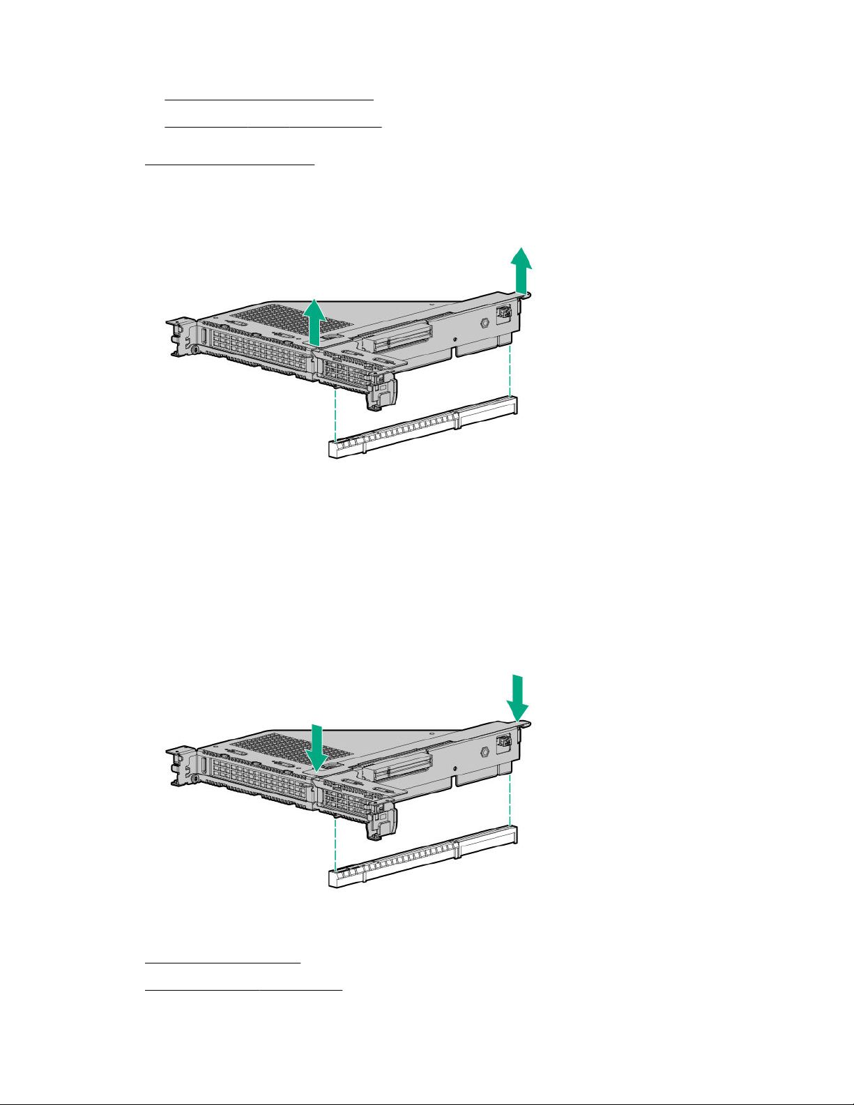
5. Do one of the following:
• Extend the server from the rack.
• Remove the server from the rack.
6. Remove the access panel.
7. Remove the PCI riser cage.
Installing the primary PCI riser cage
Procedure
1. Install the PCI riser cage.
2. Install the access panel.
3. Install the server into the rack.
42 Operations
Page 43

4. Connect each power cord to the server.
5. Connect each power cord to the power source.
6. Power up the server.
7. If removed, install the bezel.
Removing the secondary PCI riser cage
Procedure
1. Observe the following alerts:
CAUTION: To prevent damage to the server or expansion boards, power down the server and
remove all AC power cords before removing or installing the PCI riser cage.
CAUTION: To prevent improper cooling and thermal damage, do not operate the server unless
all bays are populated with either a component or a blank.
2. Back up all server data.
3. If installed, remove the bezel.
4. Power down the server.
5. Remove all power:
a. Disconnect each power cord from the power source.
b. Disconnect each power cord from the server.
6. Do one of the following:
• Extend the server from the rack.
• Remove the server from the rack.
7. Remove the access panel.
8. Do one of the following:
• Remove the primary PCI riser blank.
Remove the primary PCI riser cage.
•
9. Disconnect any cables connected to the PCI riser cage.
10. Remove any expansion boards installed in the PCI riser cage.
Operations 43
Page 44
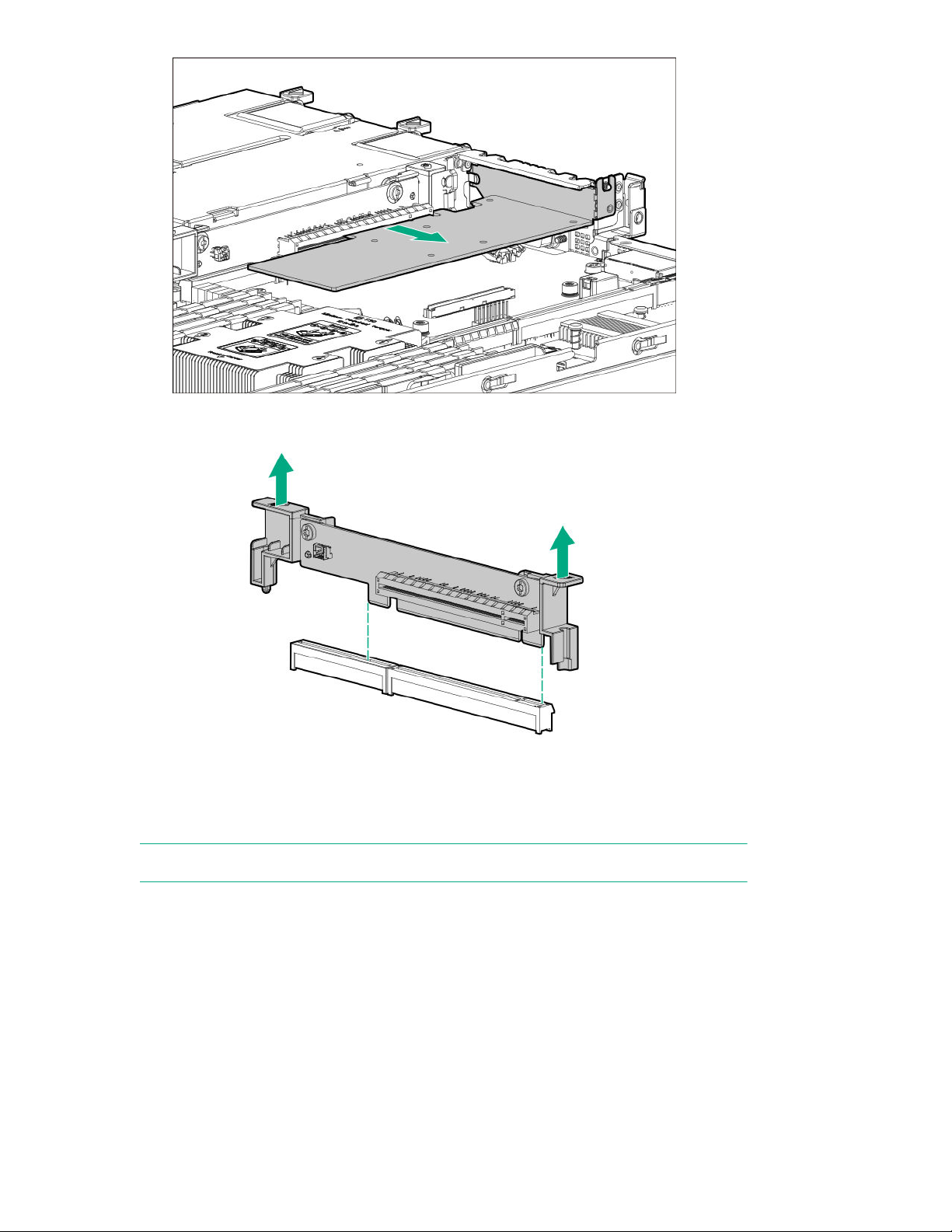
11. Remove the PCI riser cage.
Installing the secondary PCI riser cage
NOTE: If installing an expansion board into slot 3, a second processor must be installed.
Procedure
1. Install the PCI riser cage.
44 Operations
Page 45
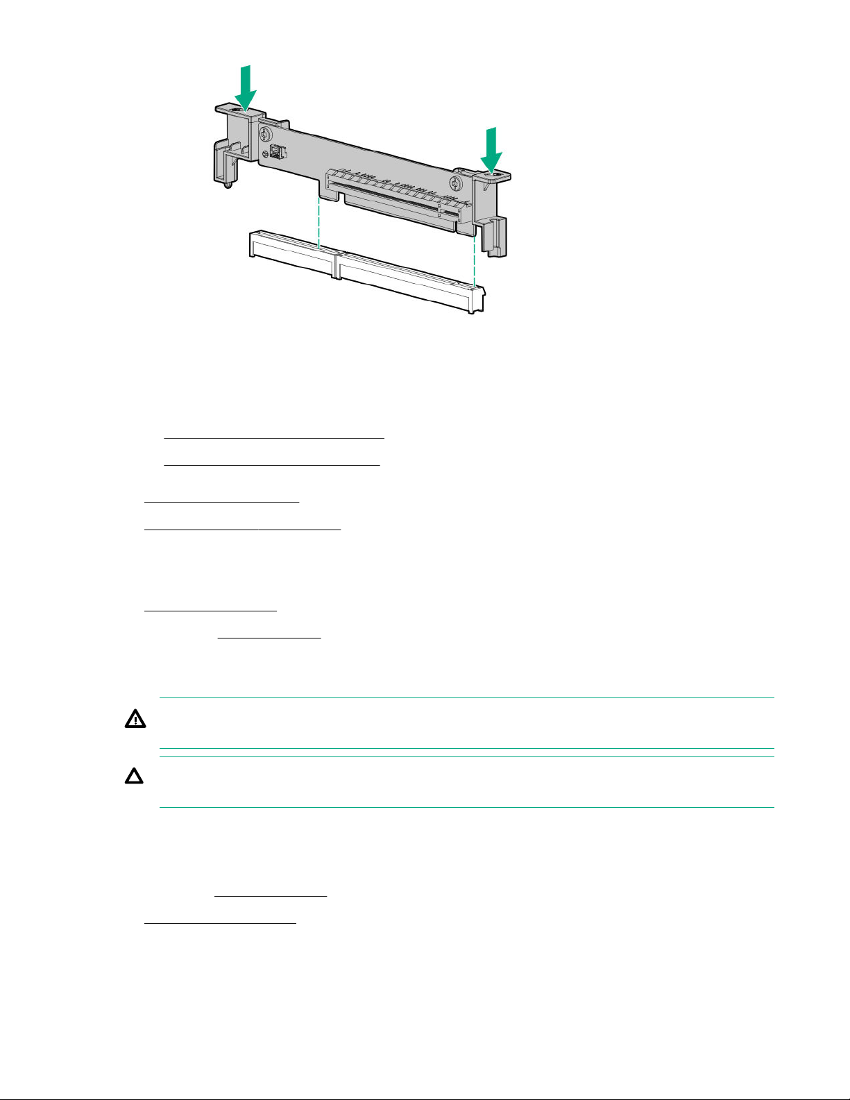
2. If needed, install expansion boards.
3. Do one of the following:
• Install the primary PCI riser blank.
• Install the primary PCI riser cage.
4. Install the access panel.
5. Install the server into the rack.
6. Connect each power cord to the server.
7. Connect each power cord to the power source.
8. Power up the server.
9. If removed, install the bezel.
Removing the expansion slot blank
WARNING: To reduce the risk of personal injury from hot surfaces, allow the drives and the internal
system components to cool before touching them.
CAUTION: To prevent damage to electrical components, properly ground the server before
beginning any installation procedure. Improper grounding can cause electrostatic discharge.
Procedure
1. Back up all server data.
2. If installed, remove the bezel.
3. Power down the server.
4. Remove all power:
Operations 45
Page 46
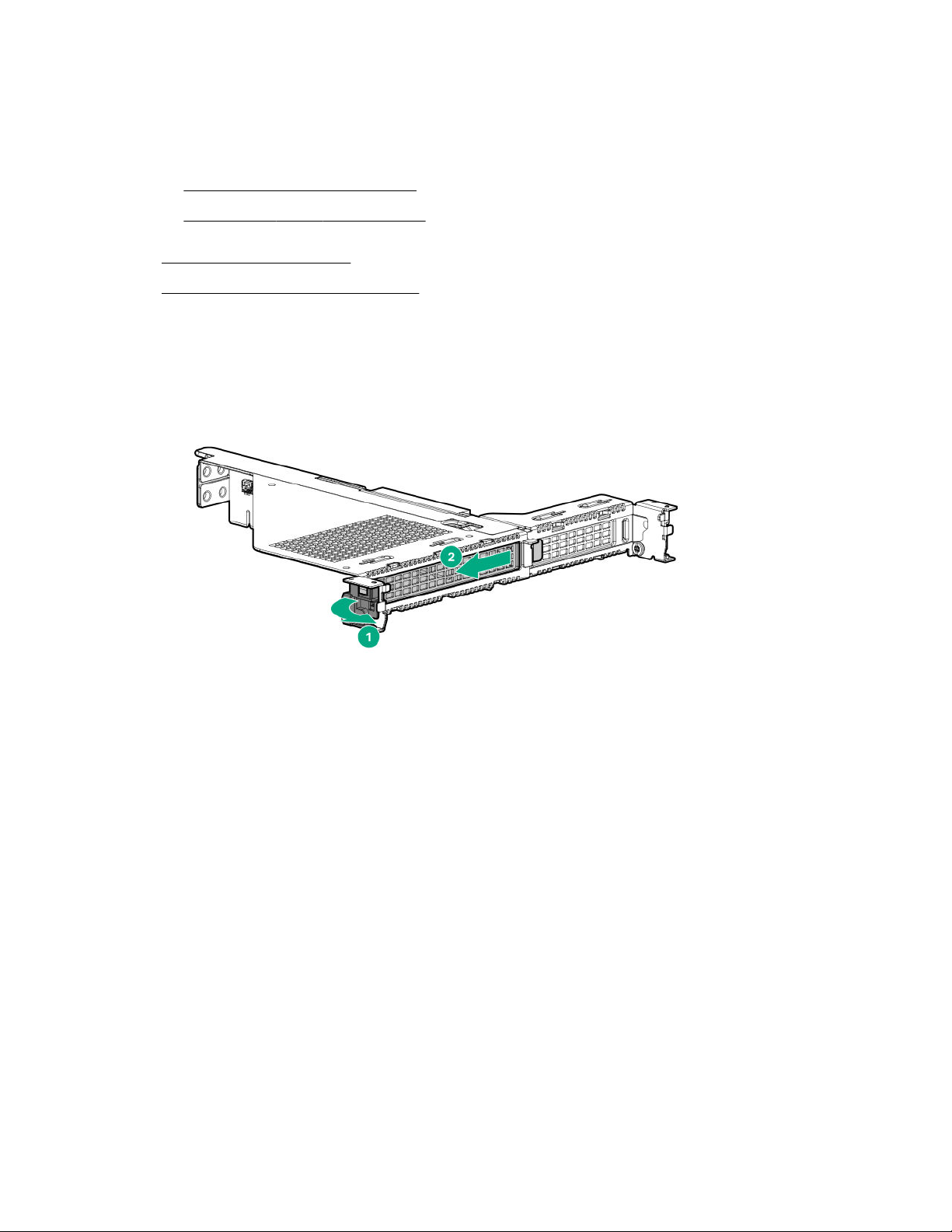
a. Disconnect each power cord from the power source.
b. Disconnect each power cord from the server.
5. Do one of the following:
• Extend the server from the rack.
• Remove the server from the rack.
6. Remove the access panel.
7. Remove the primary PCI riser cage.
8. Remove the expansion slot blank:
• Slot 1 of the x16 x8 primary riser
• Slot 2
46 Operations
Page 47
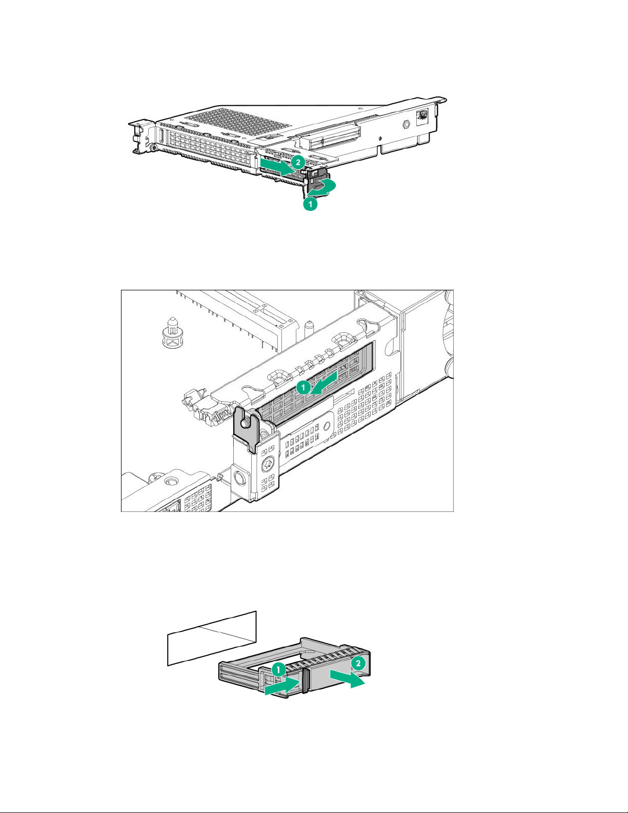
• Slot 3
Removing and replacing a drive blank
Remove the components as indicated.
• SFF drive blank
• Low-profile LFF drive blank
Operations 47
Page 48
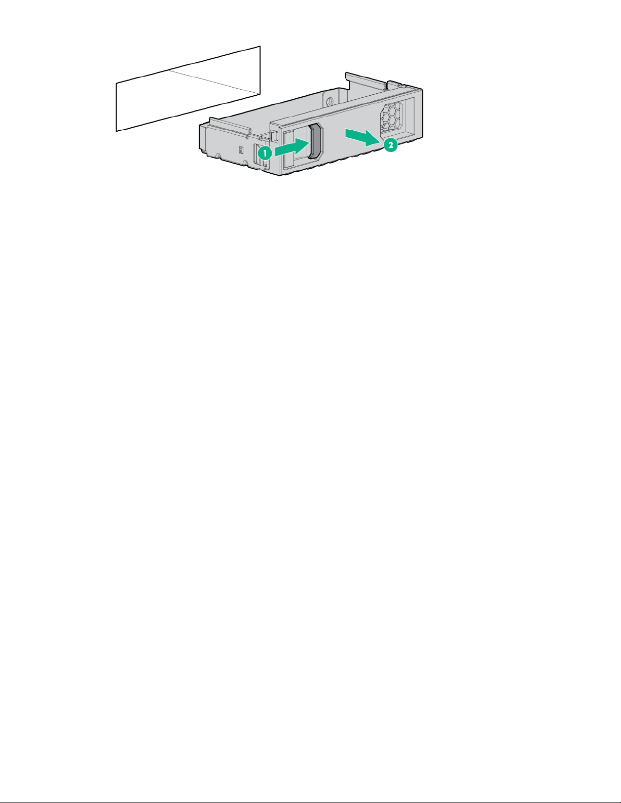
To replace the blank, slide the blank into the bay until it locks into place.
48 Operations
Page 49
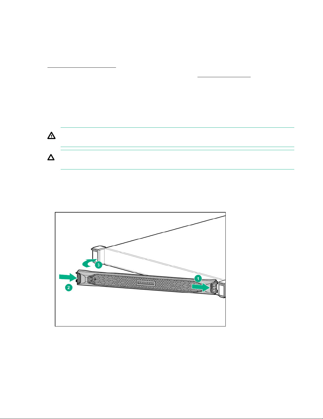
Hardware options installation
This chapter provides detailed instructions on how to install hardware options.
For more information on supported options, see the product QuickSpecs on the website at:
http://www.hpe.com/info/qs
To view the warranty for your server and supported options, see Warranty information on page 135.
Introduction
Install any hardware options before initializing the server. For options installation information, see the
option documentation. For server-specific information, use the procedures in this section.
If multiple options are being installed, read the installation instructions for all the hardware options to
identify similar steps and streamline the installation process.
WARNING: To reduce the risk of personal injury from hot surfaces, allow the drives and the internal
system components to cool before touching them.
CAUTION: To prevent damage to electrical components, properly ground the server before
beginning any installation procedure. Improper grounding can cause electrostatic discharge.
Installing the front bezel option
Procedure
1. Install the front bezel.
2. Install the Kensington security lock.
For more information, see the lock documentation.
The installation is complete.
Hardware options installation 49
Page 50

Redundant power supply enablement option
The RPS enablement option supports the installation of two Gen10 Flexible Slot (Flex Slot) power
supplies.
Adding a second power supply provides redundant power support to the server if one power supply fails.
You do not have to power down the server before removing or installing a redundant hot-plug power
supply.
Kit contents
• Redundant power supply cage
• Power distribution board
Installing the redundant power supply enablement kit
Prerequisites
Before you perform this procedure, make sure that you have the following items available:
• The components included with the hardware option kit
• T-15 Torx screwdriver
• T-10 Torx screwdriver
• Hot-plug power supply
Procedure
1. Back up all server data.
2. If installed, remove the bezel.
3. Power down the server.
4. Access the product rear panel.
5. Release the power cord from the strain relief clip.
6. Remove all power:
a. Disconnect each power cord from the power source.
b. Disconnect each power cord from the server.
7. Remove the server from the rack.
8. Place the server on a sturdy, level surface.
9. Remove the access panel.
10. Remove the rail.
a. Extend the rail.
50 Hardware options installation
Page 51
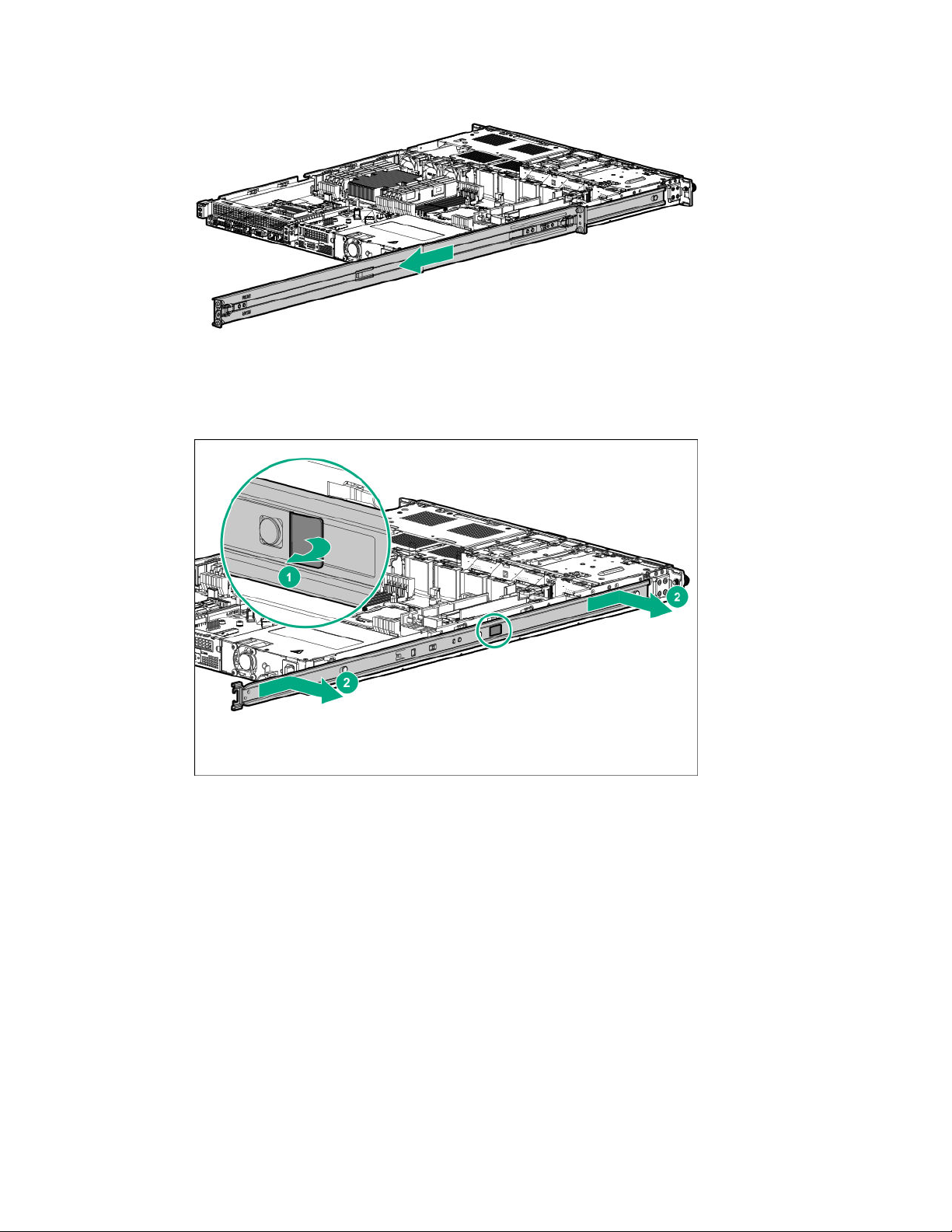
b. Remove the rail from the server.
11. Remove the non-hot-plug power supply.
Hardware options installation 51
Page 52
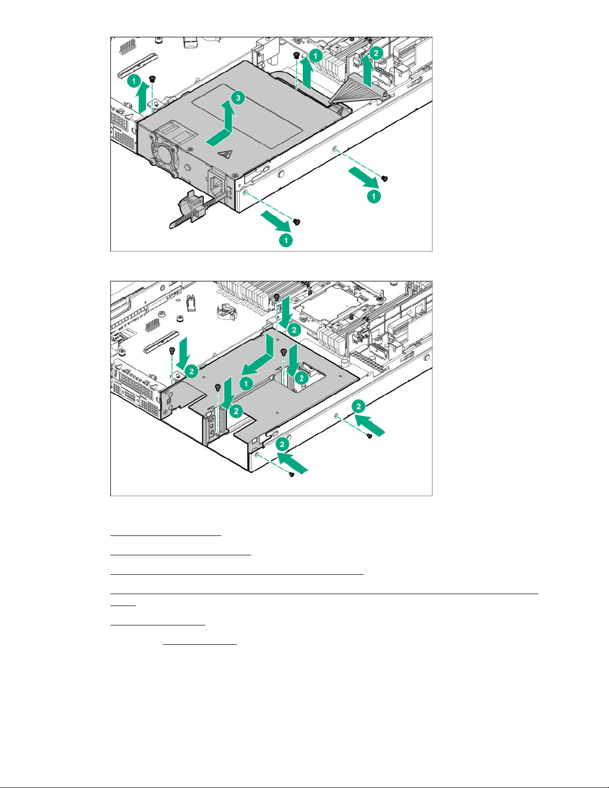
12. Install the redundant power supply cage.
13. Install the rail.
14. Install the access panel.
15. Install the server into the rack.
16. Install a hot-plug power supply in power supply bay 1.
17. If enabling power redundancy in the server, install a second power supply in power supply
bay 2.
18. Power up the server on page 36.
19. If removed, install the bezel.
The installation is complete.
52 Hardware options installation
Page 53
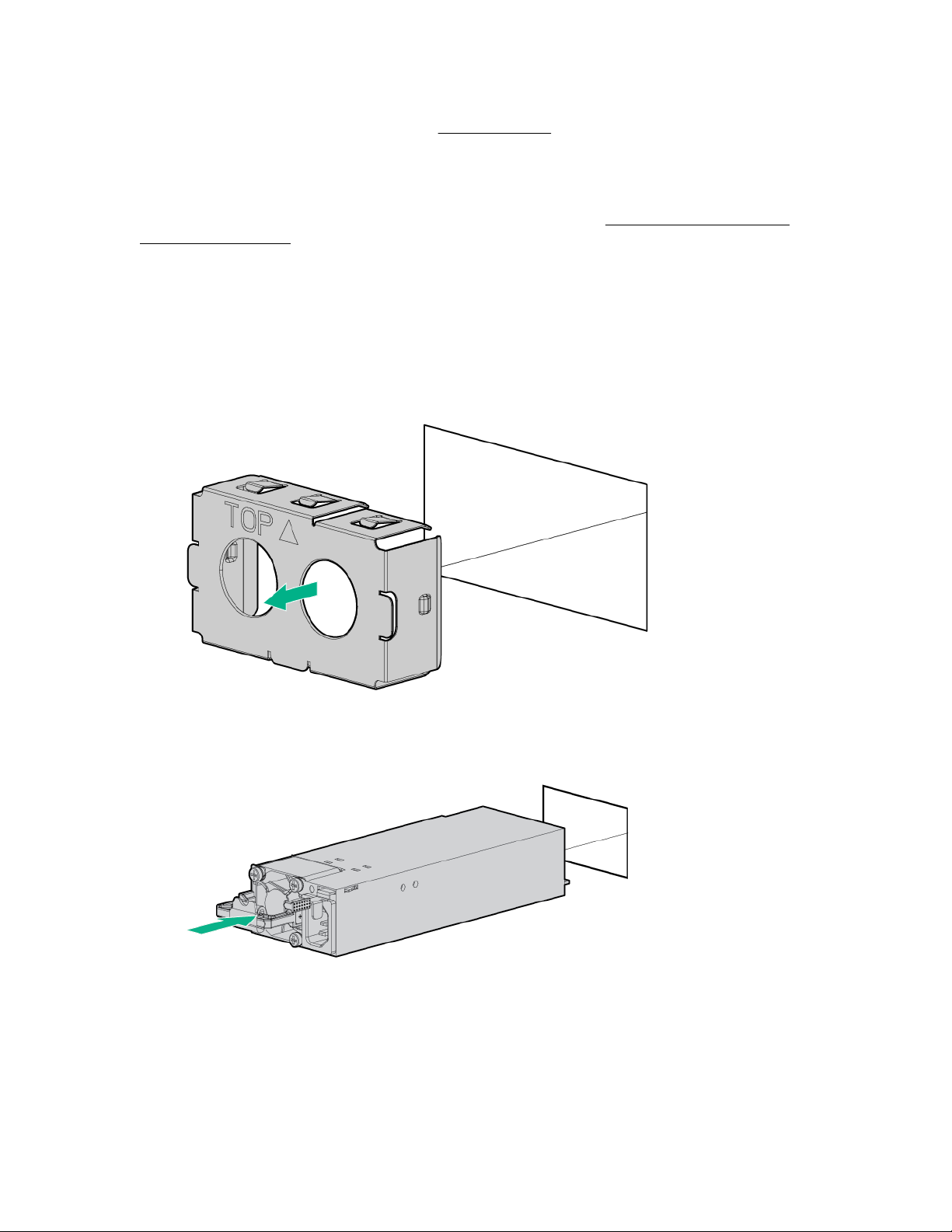
Power supply options
Depending on the installed options and the regional location where the server was purchased, the server
can be configured with one of the following power supplies.
Hot-plug power supply calculations
For hot-plug power supply specifications and calculators to determine electrical and heat loading for the
server, see the Hewlett Packard Enterprise Power Advisor website (http://www.hpe.com/info/
poweradvisor/online).
Installing a hot-plug AC power supply
Procedure
1. Access the product rear panel.
2. Remove the power supply blank.
3. Slide the power supply into the bay until it clicks into place.
4. Connect the power cord to the power supply.
5. To prevent accidental power cord disconnection when sliding the server in and out of the rack, secure
the power cord in the strain relief strap attached to the power supply handle:
a. Unwrap the strain relief strap from the power supply handle.
Hardware options installation 53
Page 54
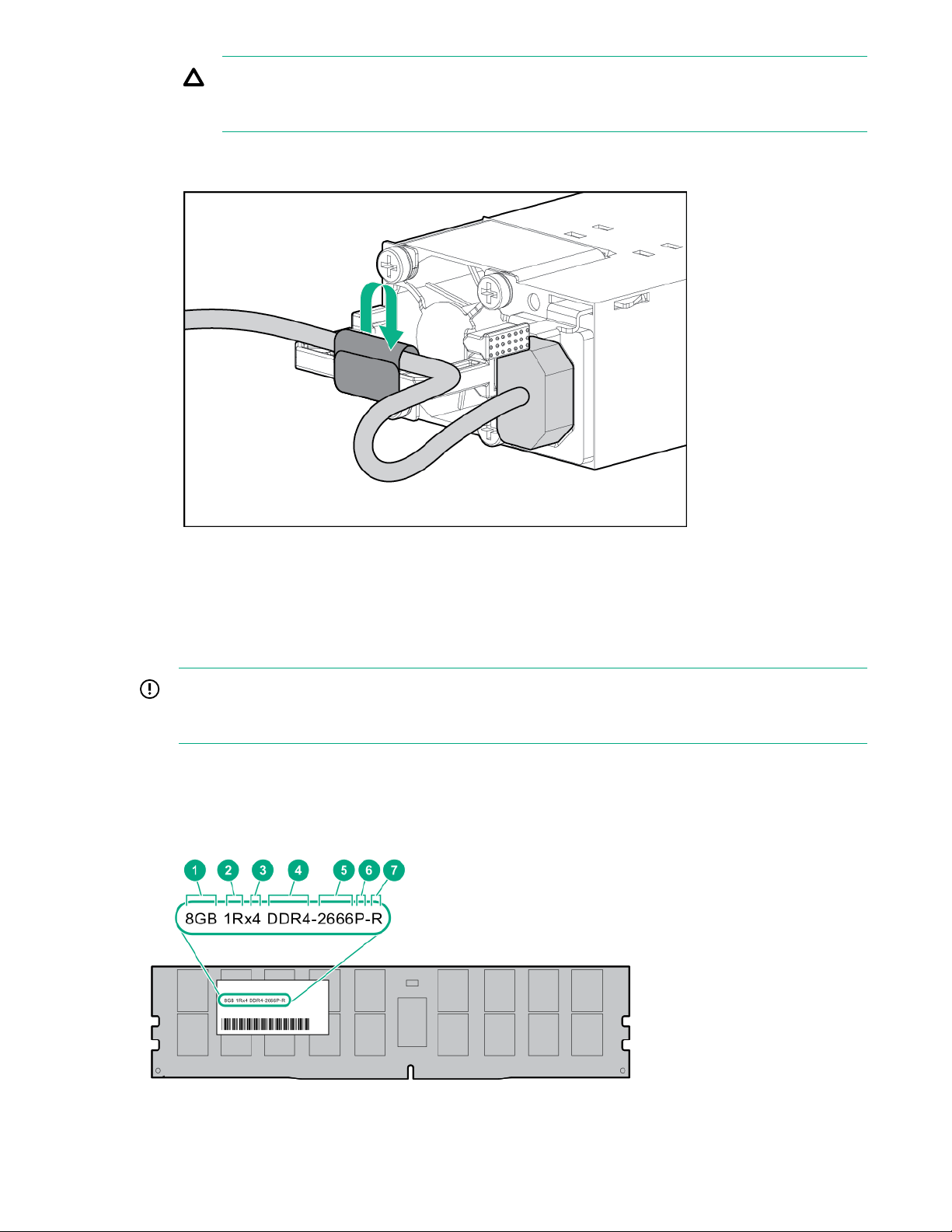
CAUTION: Avoid tight bend radii to prevent damaging the internal wires of a power cord or a
server cable. Never bend power cords and server cables tight enough to cause a crease in
the sheathing.
b. Secure the power cord with the strain relief strap. Roll the extra length of the strap around the
power supply handle.
6. Connect the power cord to the AC power source.
7. Be sure that the power supply LED is green.
Memory options
IMPORTANT: This server does not support mixing LRDIMMs and RDIMMs. Attempting to mix any
combination of these DIMMs can cause the server to halt during BIOS initialization. All memory
installed in the server must be of the same type.
DIMM label identification
To determine DIMM characteristics, see the label attached to the DIMM. The information in this section
helps you to use the label to locate specific information about the DIMM.
54 Hardware options installation
Page 55

Item Description Example
1 Capacity
2 Rank
3 Data width on DRAM
4 Memory generation
5 Maximum memory speed
8 GB
16 GB
32 GB
64 GB
128 GB
1R = Single rank
2R = Dual rank
4R = Quad rank
8R = Octal rank
x4 = 4-bit
x8 = 8-bit
x16 = 16-bit
PC4 = DDR4
2133 MT/s
2400 MT/s
6 CAS latency
7 DIMM type
For more information about product features, specifications, options, configurations, and compatibility, see
the product QuickSpecs on the Hewlett Packard Enterprise website (http://www.hpe.com/info/qs).
Installing a DIMM
For specific DIMM population and memory speed information, see the product QuickSpecs on the Hewlett
Packard Enterprise website (http://www.hpe.com/info/qs).
Procedure
2666 MT/s
P = CAS 15-15-15
T = CAS 17-17-17
U = CAS 20-18-18
V = CAS 19-19-19 (for RDIMM, LRDIMM)
V = CAS 22-19-19 (for 3DS TSV LRDIMM)
R = RDIMM (registered)
L = LRDIMM (load reduced)
E = Unbuffered ECC (UDIMM)
1. Back up all server data.
2. If installed, remove the bezel.
3. Power down the server.
Hardware options installation 55
Page 56
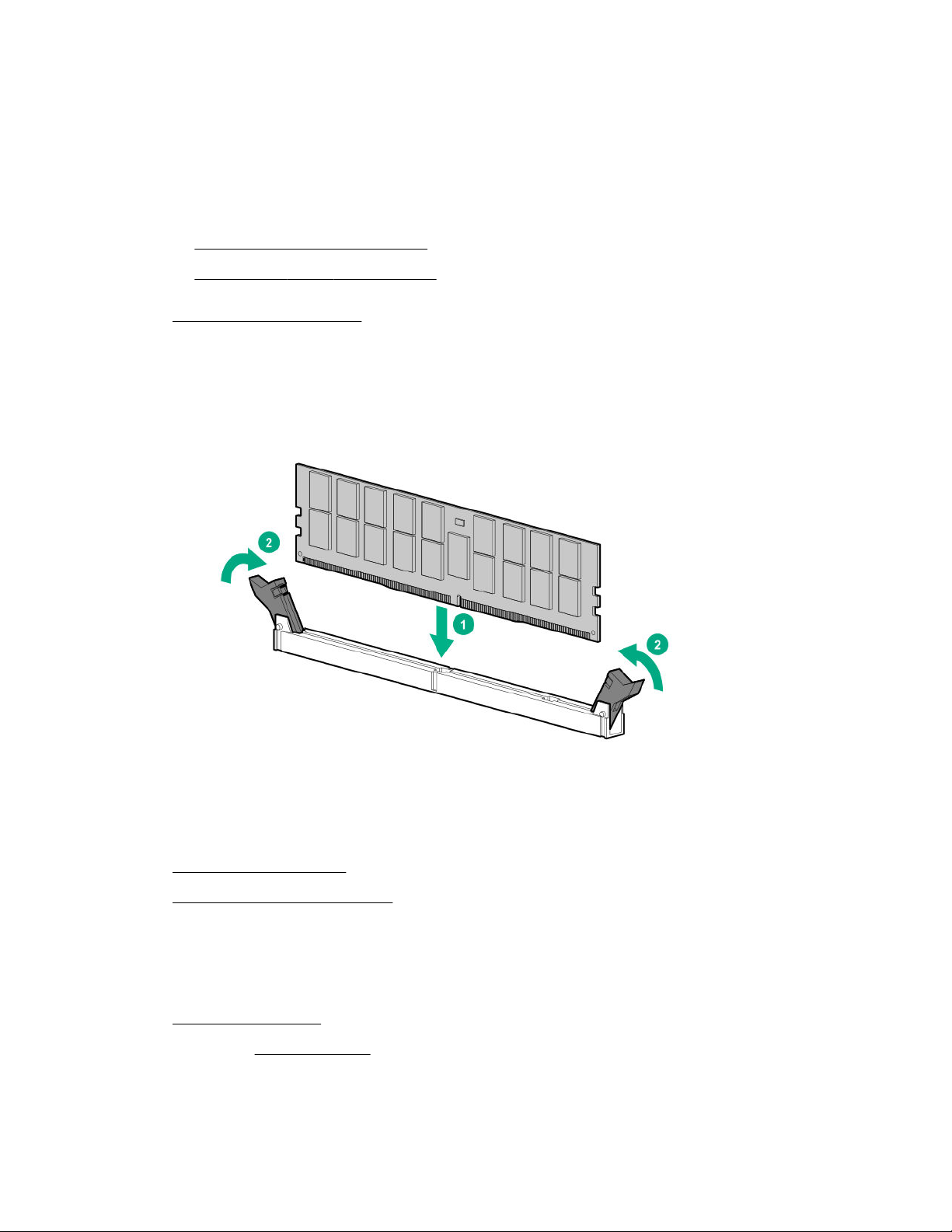
4. Remove all power:
a. Disconnect each power cord from the power source.
b. Disconnect each power cord from the server.
5. Disconnect all peripheral cables from the server.
6. Do one of the following:
• Extend the server from the rack.
• Remove the server from the rack.
7. Remove the access panel.
8. Install the DIMM:
a. Open the DIMM slot latches.
b. Align the notch on the bottom edge of the DIMM with the keyed surface of the DIMM slot, and
then fully press the DIMM into the slot until the latches snap back into place.
The DIMM slots are structured to ensure proper installation. If you try to insert a DIMM but it does
not fit easily into the slot, you might have positioned it incorrectly. Reverse the orientation of the
DIMM and insert it again.
9. Install the access panel.
10. Install the server into the rack.
11. Connect all peripheral cables to the server.
12. Connect each power cord to the server.
13. Connect each power cord to the power source.
14. Power up the server.
15. If removed, install the bezel.
The installation is complete.
56 Hardware options installation
Page 57
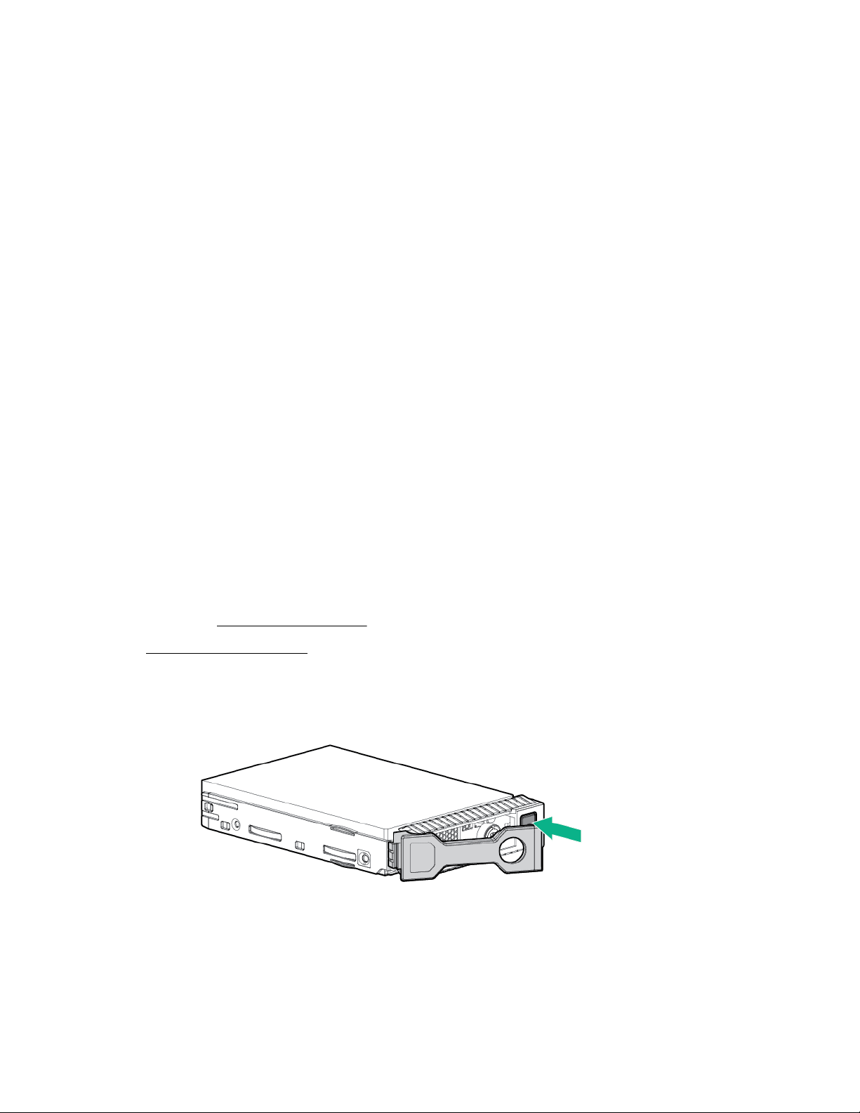
After installing the DIMMs, use the System Utilities > System Configuration > BIOS/Platform
Configuration (RBSU) > Memory Options to configure the memory settings.
Drive options
Hot-plug drive guidelines
When adding drives to the server, observe the following general guidelines:
• The system automatically sets all device numbers.
• If only one drive is used, install it in the bay with the lowest device number.
• Drives should be the same capacity to provide the greatest storage space efficiency when drives are
grouped together into the same drive array.
Drive support information
Depending on the drive cage option installed, the server supports the following drive types:
• Hot-plug LFF SATA or SAS drives
• Hot-plug SFF SATA or SAS drives
• Hot-plug NVMe SSDs
The embedded HPE Smart Array S100i SR Gen10 Controller supports SATA drive installation. For SAS
support, install a Smart Array Gen10 type-a or type-p controller option.
Installing a hot-plug SAS or SATA drive
Procedure
1. If installed, remove the front bezel.
2. Remove the drive blank.
3. Prepare the drive.
• SFF drive
• LFF hot-plug drive
Hardware options installation 57
Page 58
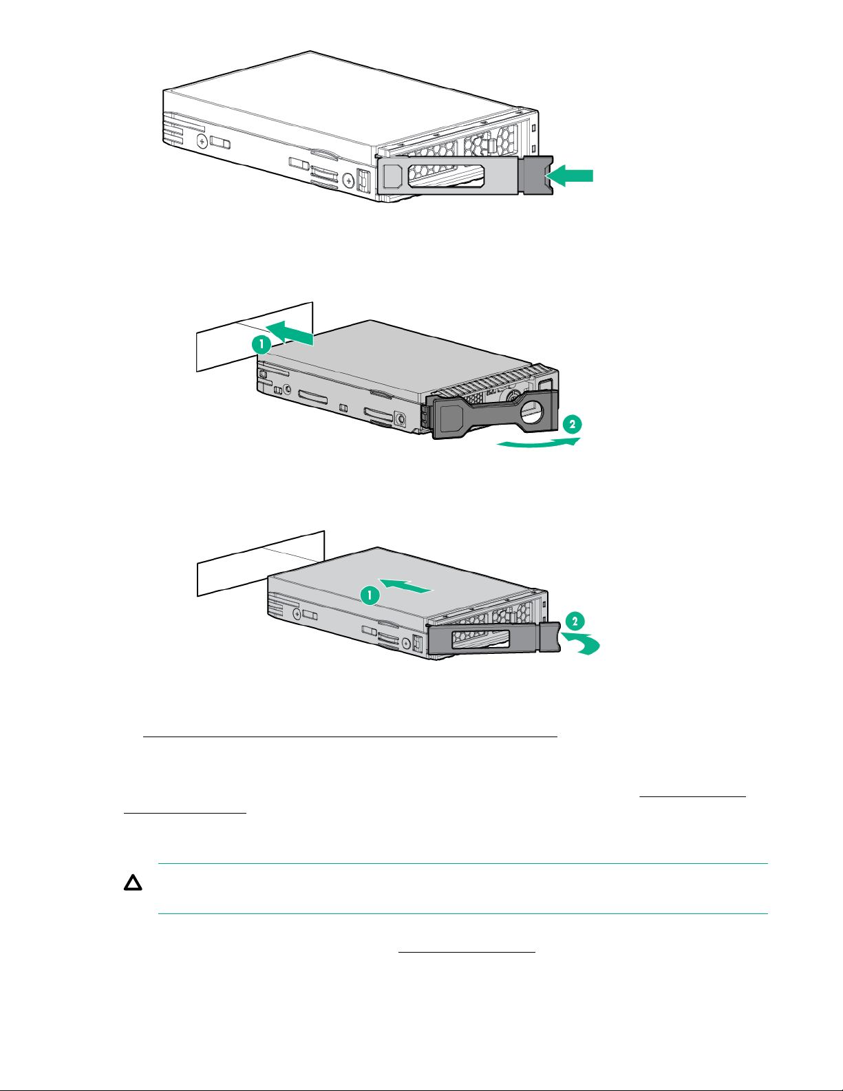
4. Install the drive.
• SFF drive
• LFF hot-plug drive
5. Determine the status of the drive from the drive LED definitions.
The installation is complete.
To configure arrays, see the HPE Smart Array SR Gen10 Configuration Guide at the Hewlett Packard
Enterprise website.
Installing the NVMe drives
CAUTION: To prevent improper cooling and thermal damage, do not operate the server unless all
bays are populated with either a component or a blank.
NVMe drives are supported in the eight-bay SFF drive model when the two-bay SFF NVMe enablement
option is installed. For more information, see Drive bay numbering.
58 Hardware options installation
Page 59
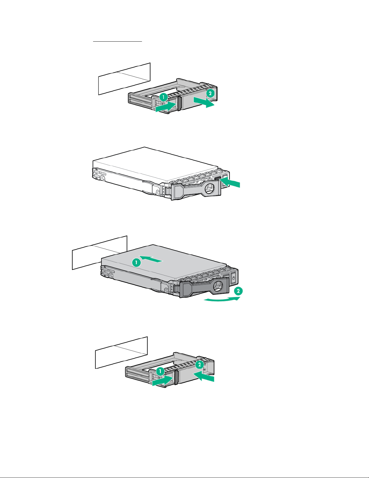
Procedure
1. If installed, remove the bezel.
2. If installed, remove the drive blank.
3. Press the Do Not Remove button to open the release handle.
4. Install the drives.
5. Install an SFF drive blank in any unused drive bays.
The installation is complete.
Hardware options installation 59
Page 60

Most current operating systems provide an NVMe SSD driver natively. Use this native (inbox) driver to
configure and deploy NVMe SSDs.
The SmartSSD Wear Gauge reports in the HPE Smart Storage Administrator contain information about
the current usage level and remaining expected lifetime of SSDs attached to the system. For more
information, see the HPE Smart Array SR Gen10 Configuration Guide at the Hewlett Packard
Enterprise website.
Installing a two-bay SFF enablement kit
Prerequisites
Before you perform this procedure, make sure that you have the following items available:
• T-10 Torx screwdriver
• The appropriate cables needed for the installation. For more information, see cabling.
• 2 SFF drives or blanks.
• If installing the two-bay SFF NVMe enablement kit, the FlexibleLOM/NVMe riser cage must be
installed.
For more information, contact HPE Authorized Resellers.
Procedure
1. Back up all server data.
2. If installed, remove the bezel.
3. Power down the server.
4. Remove all power:
a. Disconnect each power cord from the power source.
b. Disconnect each power cord from the server.
5. Disconnect all peripheral cables from the server.
6. Do one of the following:
• Extend the server from the rack.
• Remove the server from the rack.
Remove the access panel.
7.
8. Remove the universal media bay blank.
60 Hardware options installation
Page 61
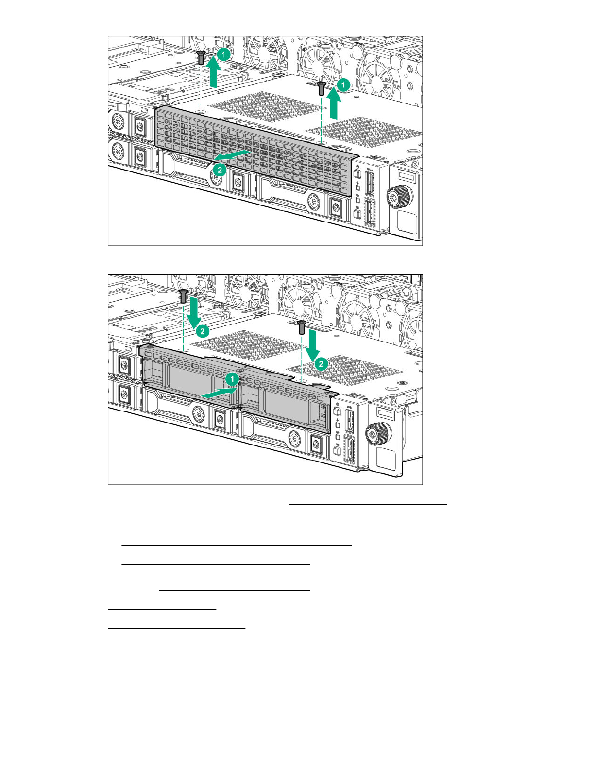
9. Install the drive cage.
10. If installing the two-bay NVMe drive cage, remove the primary PCI riser cage.
11. Route and connect the cables.
• Cabling for the two-bay SFF SAS/SATA drive cage
• Cabling for the two-bay NVMe drive cage
12. If removed, install the primary PCI riser cage.
13. Install the access panel.
14. Install the server into the rack.
15. Connect all peripheral cables to the server.
16. Connect each power cord to the server.
17. Connect each power cord to the power source.
Hardware options installation 61
Page 62

18. Power up the server.
19. Install drives.
20. If removed, install the bezel.
The installation is complete.
Installing the Slim SSD enablement kit
This option is only supported in four-bay LFF models.
Prerequisites
Before you perform this procedure, make sure that you have the following items available:
• T-10 Torx screwdriver
• Slim SSD
Procedure
1. Back up all server data.
2. If installed, remove the bezel.
3. Power down the server.
4. Remove all power:
a. Disconnect each power cord from the power source.
b. Disconnect each power cord from the server.
5. Disconnect all peripheral cables from the server.
6. Do one of the following:
• Extend the server from the rack.
• Remove the server from the rack.
7. Remove the access panel.
8. Remove the primary PCI riser cage.
9. Install the holder onto the SDD with one screw.
62 Hardware options installation
Page 63
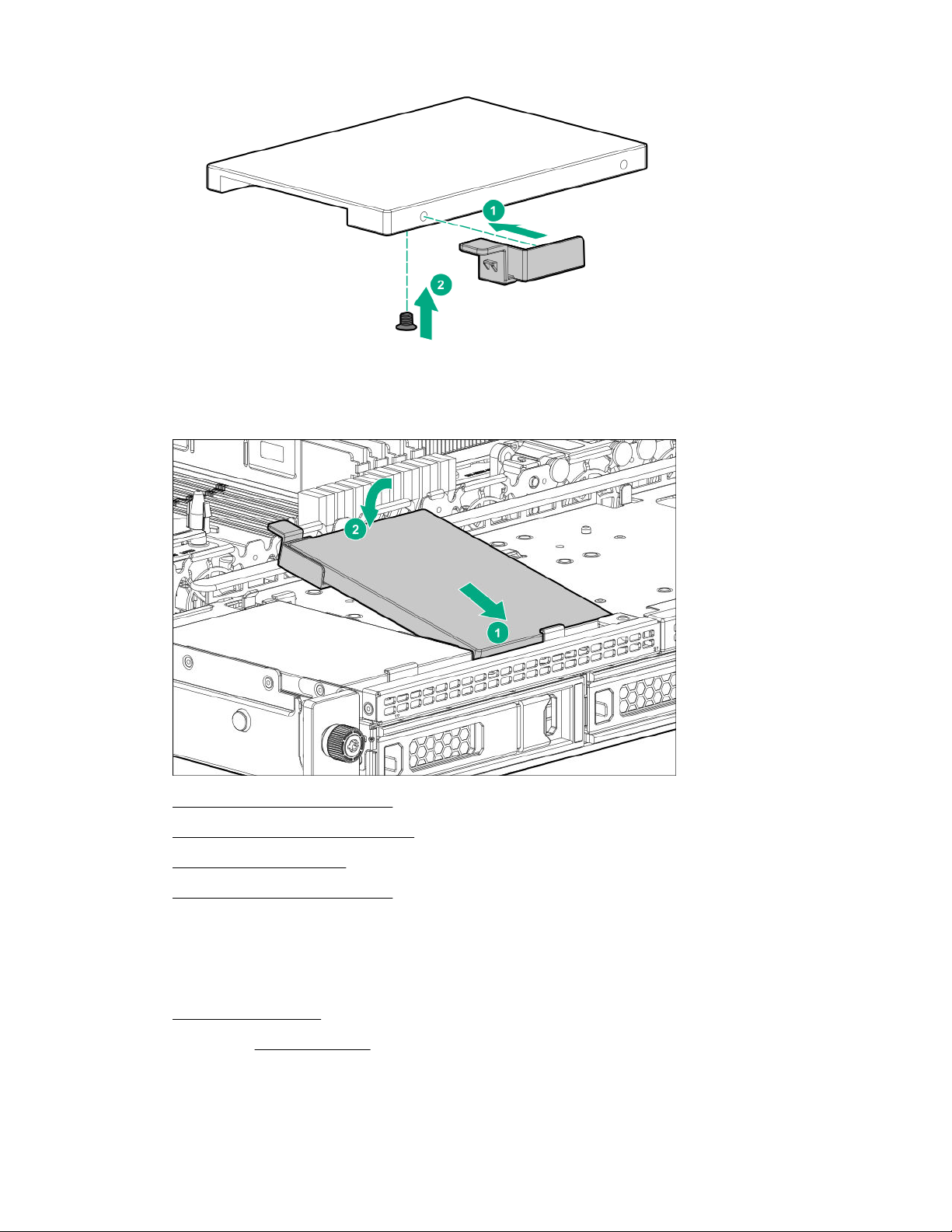
10. Install the SSD into the server.
11. Route and connect the cables.
12. Install the primary PCI riser cage.
13. Install the access panel.
14. Install the server into the rack.
15. Connect all peripheral cables to the server.
16. Connect each power cord to the server.
17. Connect each power cord to the power source.
18. Power up the server.
19. If removed, install the bezel.
The installation is complete.
Hardware options installation 63
Page 64

Redundant fan option
Fan population guildlines
Configuration Bay 1 Bay 2 Bay 3 Bay 4 Bay 5 Bay 6 Bay 7
One processor, nonredundant
One processor,
redundant
Two processors, nonredundant
Two processors,
redundant
Fan mode behavior
• In nonredundant fan mode, a fan failure or a missing fan causes:
◦ The system Health LED to flash amber.
◦ The operating system to orderly shutdown.
• In redundant fan mode:
◦ A fan rotor failure will switch the system to nonredundant fan mode.
This change is indicated by the Health LED flashing amber. The system continues to operate
normally in this mode.
Blank Blank Blank Blank Fan Fan Fan
Blank Blank Fan Blank Fan Fan Fan
Blank Fan Fan Fan Fan Fan Fan
Fan Fan Fan Fan Fan Fan Fan
◦ A second fan rotor failure or a missing fan causes the operating system to orderly shutdown.
Installing a fan
CAUTION: To prevent improper cooling and thermal damage, do not operate the server unless all
bays are populated with either a component or a blank.
Procedure
1. Back up all server data.
2. If installed, remove the bezel.
3. Power down the server.
4. Remove all power:
a. Disconnect each power cord from the power source.
b. Disconnect each power cord from the server.
5. Disconnect all peripheral cables from the server.
6. Do one of the following:
64 Hardware options installation
Page 65
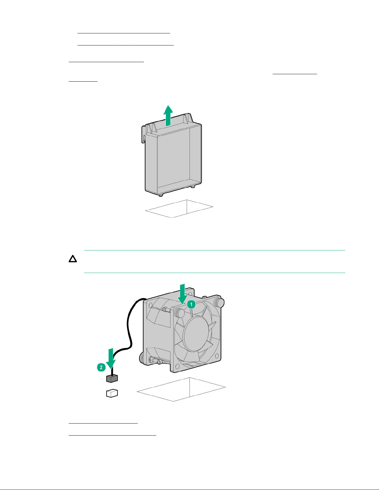
• Extend the server from the rack.
• Remove the server from the rack.
7. Remove the access panel.
8. To determine which fan blanks to remove to install the additional fans, see Fan population
guildlines on page 64.
9. Remove the fan blank.
10. Install the fan, and then connect the cable to the system board.
CAUTION: The fan lacks a fan guard. Special attention is needed when removing or installing
the fan to prevent finger injury.
11. Install the access panel.
12. Install the server into the rack.
Hardware options installation 65
Page 66
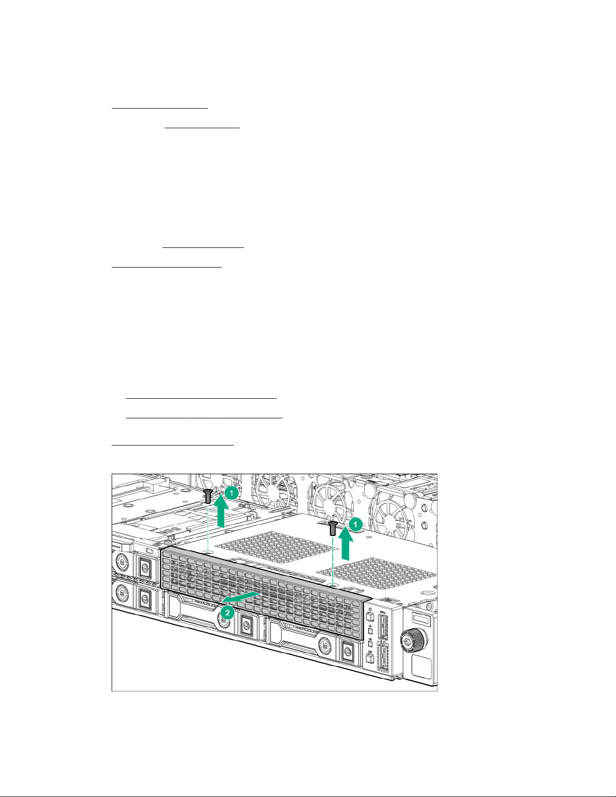
13. Connect all peripheral cables to the server.
14. Connect each power cord to the server.
15. Connect each power cord to the power source.
16. Power up the server.
17. If removed, install the bezel.
The installation is complete.
Installing the optical drive
Procedure
1. Back up all server data.
2. If installed, remove the bezel.
3. Power down the server.
4. Remove all power:
a. Disconnect each power cord from the power source.
b. Disconnect each power cord from the server.
5. Disconnect all peripheral cables from the server.
6. Do one of the following:
• Extend the server from the rack.
• Remove the server from the rack.
7. Remove the access panel.
8. If installing the option in an eight-bay SFF drive model, remove the universal media bay blank.
9. Remove the optical drive blank:
66 Hardware options installation
Page 67
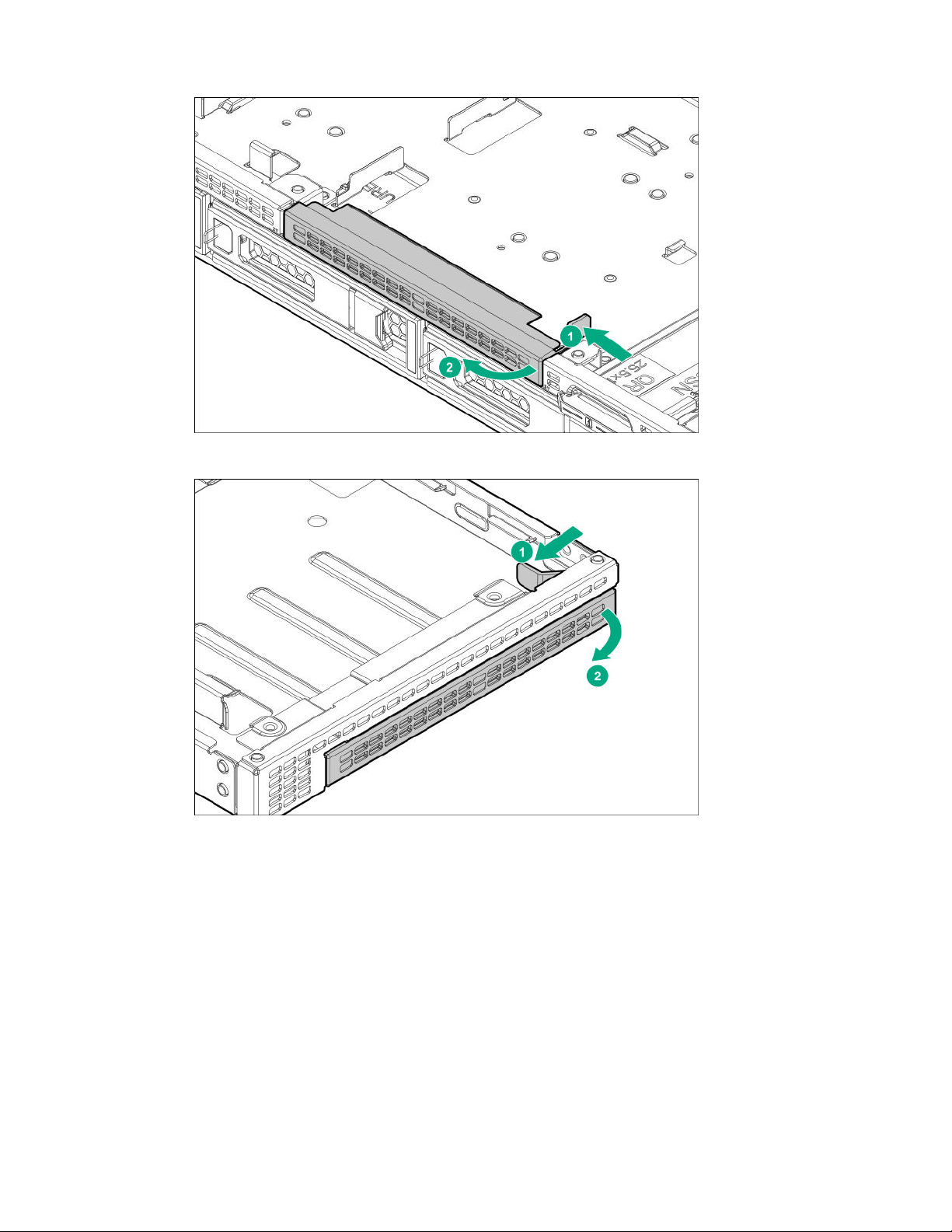
• Four-bay LFF drive model
• Eight-bay SFF drive model
Retain the blank for future use.
10. Install the optical drive.
• Four-bay LFF drive model
Hardware options installation 67
Page 68
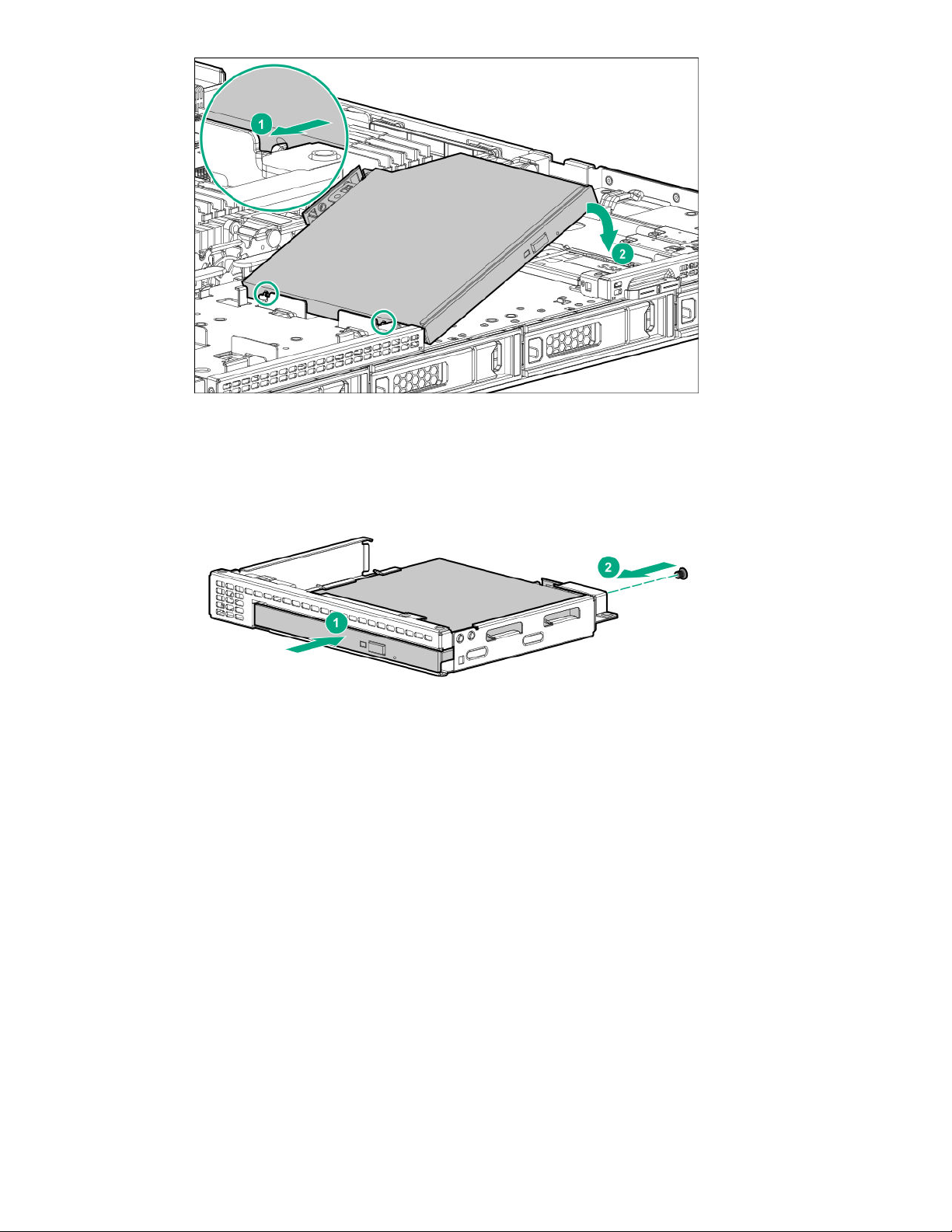
• Eight-bay SFF drive model
11. In an eight-bay SFF drive model, install the optical drive carrier.
68 Hardware options installation
Page 69
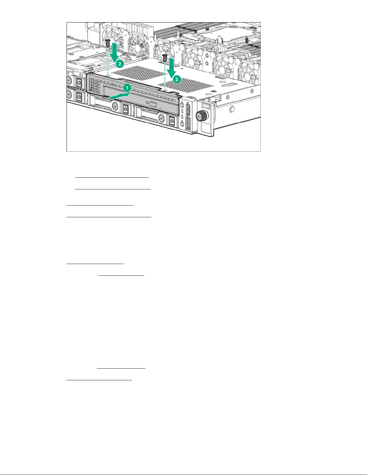
12. Connect the optical drive SATA and power cable to the optical drive.
• Four-bay LFF drive model
• Eight-bay SFF drive model
13. Install the access panel.
14. Install the server into the rack.
15. Connect all peripheral cables to the server.
16. Connect each power cord to the server.
17. Connect each power cord to the power source.
18. Power up the server.
19. If removed, install the bezel..
The installation is complete.
Installing the Media Module
Prerequisites
Before you perform this procedure, make sure that you have a T-15 Torx screwdriver available.
Procedure
1. Back up all server data.
2. If installed, remove the bezel.
3. Power down the server.
4. Remove all power:
a. Disconnect each power cord from the power source.
b. Disconnect each power cord from the server.
Hardware options installation 69
Page 70
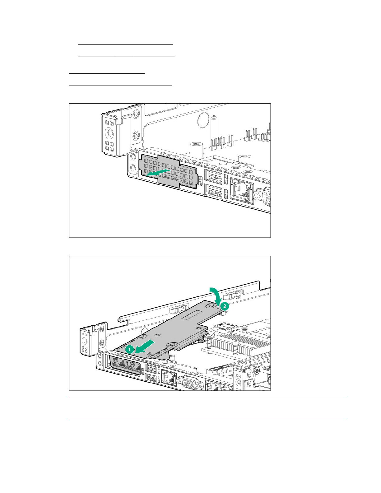
5. Do one of the following:
• Extend the server from the rack..
• Remove the server from the rack.
6. Remove the access panel.
7. Remove the primary PCI riser cage.
8. Remove the media module blank
9. Install the Media Module.
NOTE: Depending on the type of Media Module purchased, the Media Module may look slightly
different than shown.
10. Firmly seat the Media Module in the connector and ensure it is secured with the latch.
70 Hardware options installation
Page 71
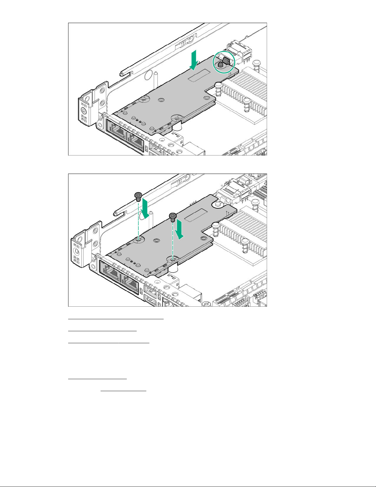
11. Secure the Media Module with two T-15 screws.
12. Install the primary PCI riser cage.
13. Install the access panel.
14. Install the server in the rack.
15. Connect each power cord to the server.
16. Connect each power cord to the power source.
17. Power up the server.
18. If removed, install the bezel.
Installing the FlexibleLOM
Prerequisites
Before you perform this procedure, make sure that you have a T-15 Torx screwdriver available.
Hardware options installation 71
Page 72
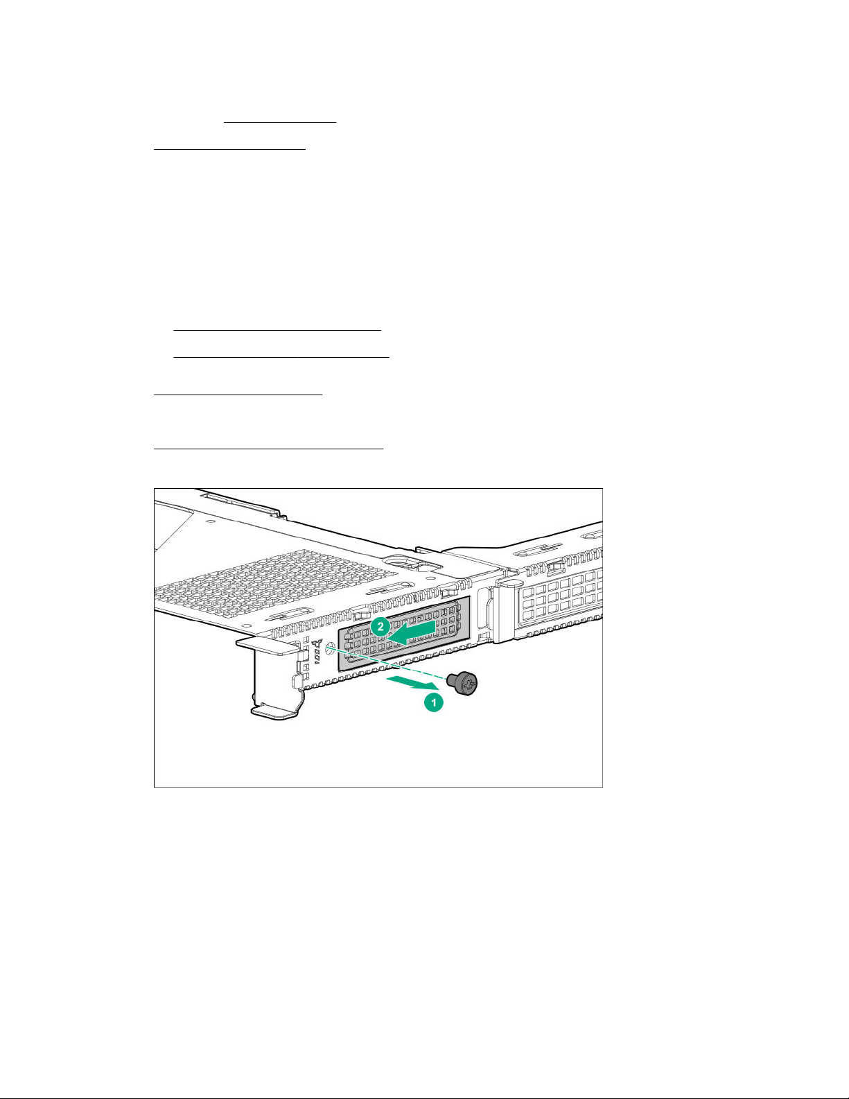
Procedure
1. Back up all server data.
2. If installed, remove the bezel.
3. Power down the server.
4. Remove all power:
a. Disconnect each power cord from the power source.
b. Disconnect each power cord from the server.
5. Disconnect all peripheral cables from the server.
6. Do one of the following:
• Extend the server from the rack.
• Remove the server from the rack.
7. Remove the access panel.
8. If necessary, disconnect any internal cables connected to the system board.
9. Remove the primary PCI riser cage.
10. Remove the blank from the FlexibleLOM slot of the riser cage.
Retain the blank for future use.
11. Install the component:
a. Firmly seat the FlexibleLOM into the slot.
b. Tighten the T-15 screw to secure the component.
72 Hardware options installation
Page 73
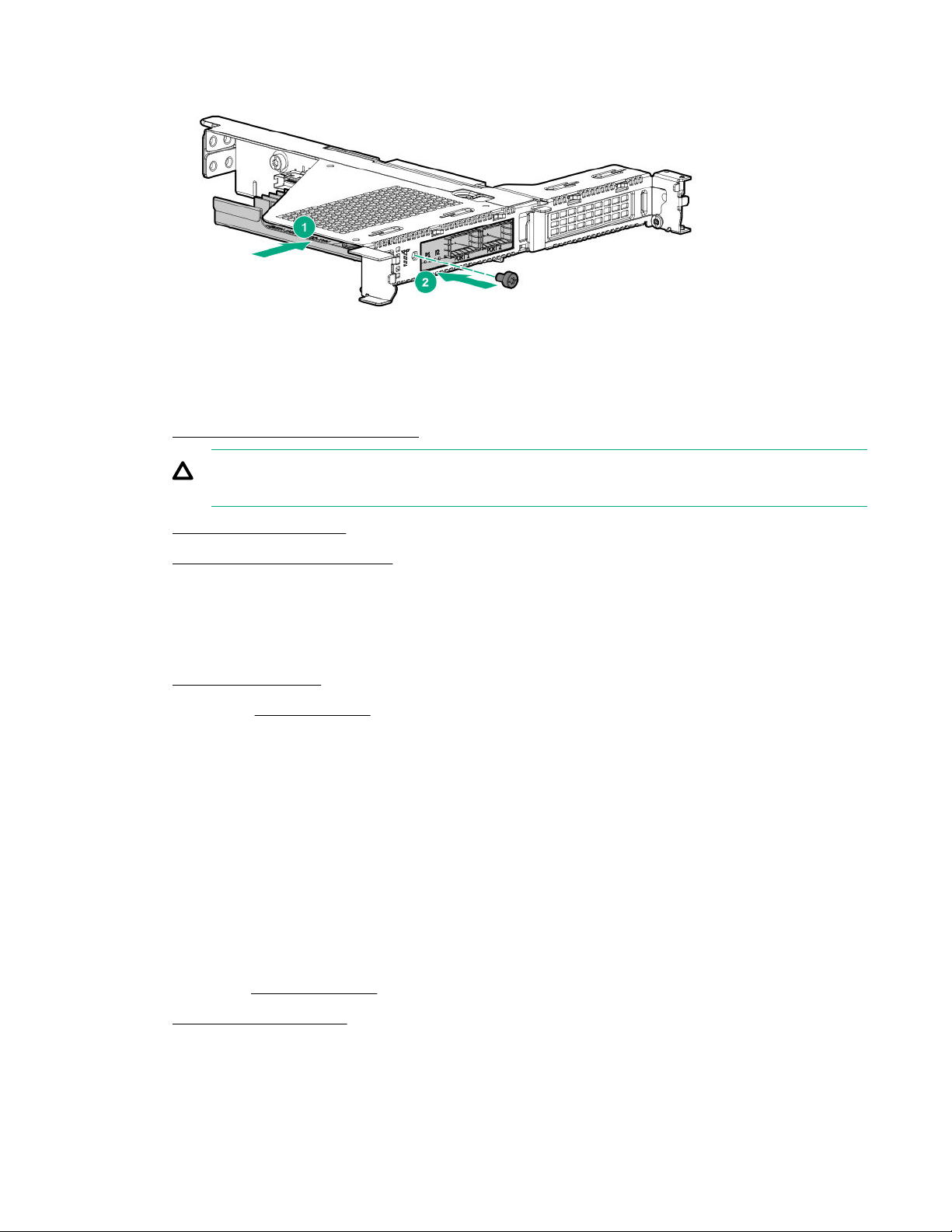
12. Install the primary PCI riser cage.
CAUTION: To prevent improper cooling and thermal damage, do not operate the server unless
all PCI slots have either an expansion slot cover or an expansion board installed.
13. Install the access panel.
14. Install the server into the rack.
15. Connect all peripheral cables to the server.
16. Connect each power cord to the server.
17. Connect each power cord to the power source.
18. Power up the server.
19. If removed, install the bezel.
The installation is complete.
Installing the serial port
Prerequisites
Before you perform this procedure, make sure that you have the following items available:
The components included with the hardware option kit
Procedure
1. Back up all server data.
2. If installed, remove the bezel.
3. Power down the server .
4. Do one of the following:
Hardware options installation 73
Page 74
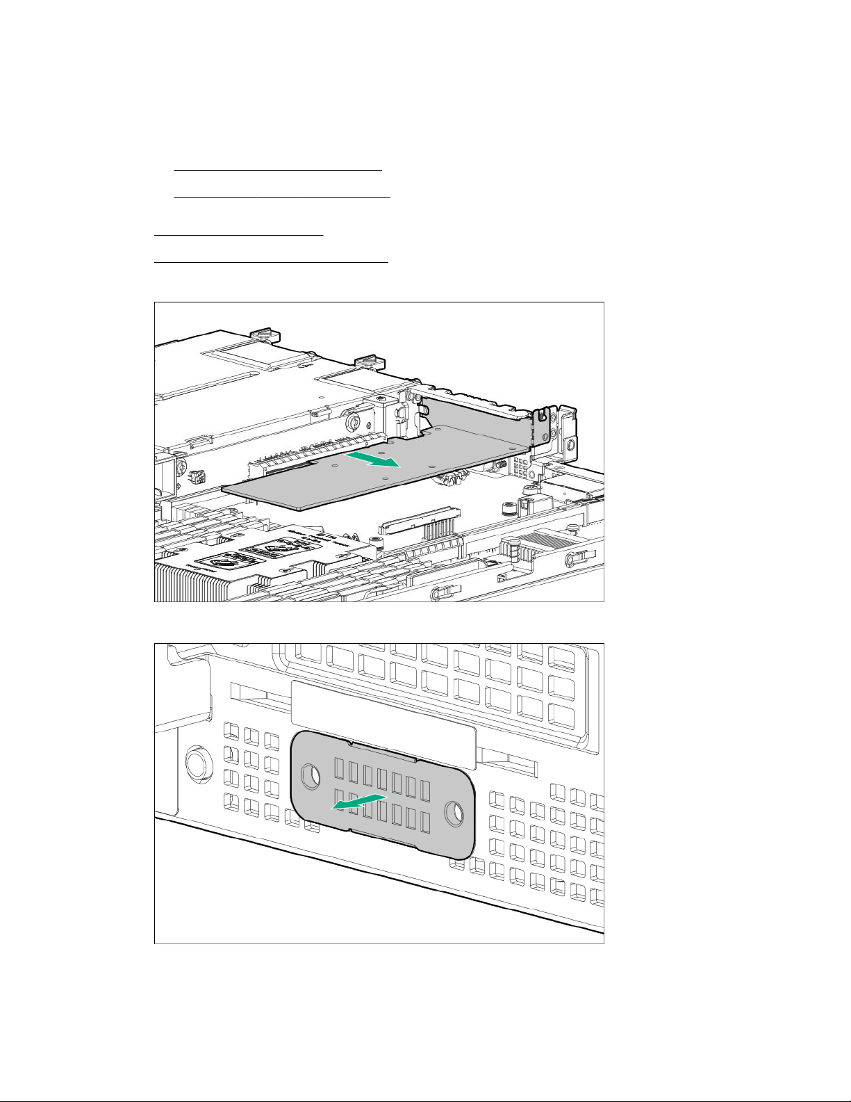
• Disconnect each power cord from the power source.
• Disconnect each power cord from the server.
5. Do one of the following:
• Extend the server from the rack.
• Remove the server from the rack.
6. Remove the access panel.
7. Remove the primary PCI riser cage.
8. If installed, remove the expansion board from slot 3.
9. Remove the serial port blank. Retain the blank for future use.
10. Install the serial port and then install the screws.
74 Hardware options installation
Page 75
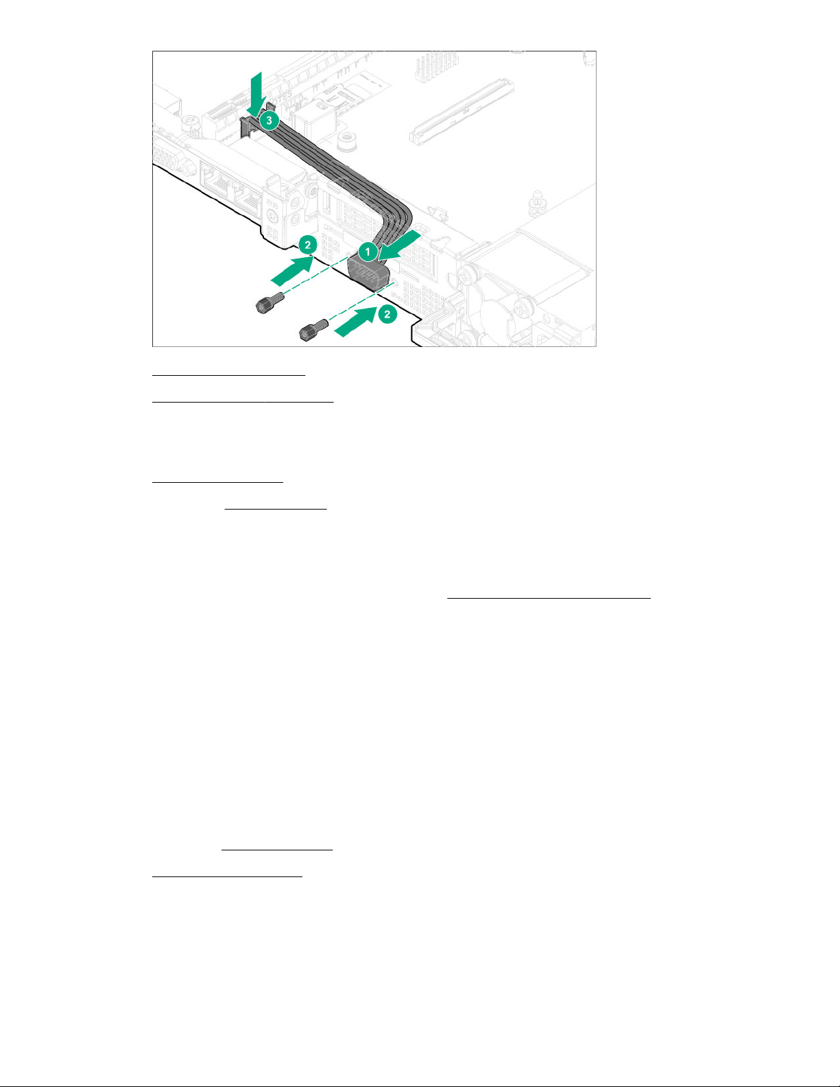
11. Install the access panel.
12. Install the server in the rack.
13. Connect each power cord to the server.
14. Connect each power cord to the power source.
15. Power up the server.
16. If removed, install the bezel.
Expansion board options
The server has three PCIe 3 expansion slots that support different form factor expansion boards. For
more information on the PCIe slot specifications, see PCIe expansion slot definitions on page 15.
Installing an expansion board
Prerequisites
If installing an expansion board into the PCIe expansion slot 3:
• Make sure that the processor 2 is installed.
• Make sure that a type-a modular storage controller is not installed.
Procedure
1. Back up all server data.
2. If installed, remove the bezel.
3. Power down the server.
4. Remove all power:
a. Disconnect each power cord from the power source.
b. Disconnect each power cord from the server.
Hardware options installation 75
Page 76
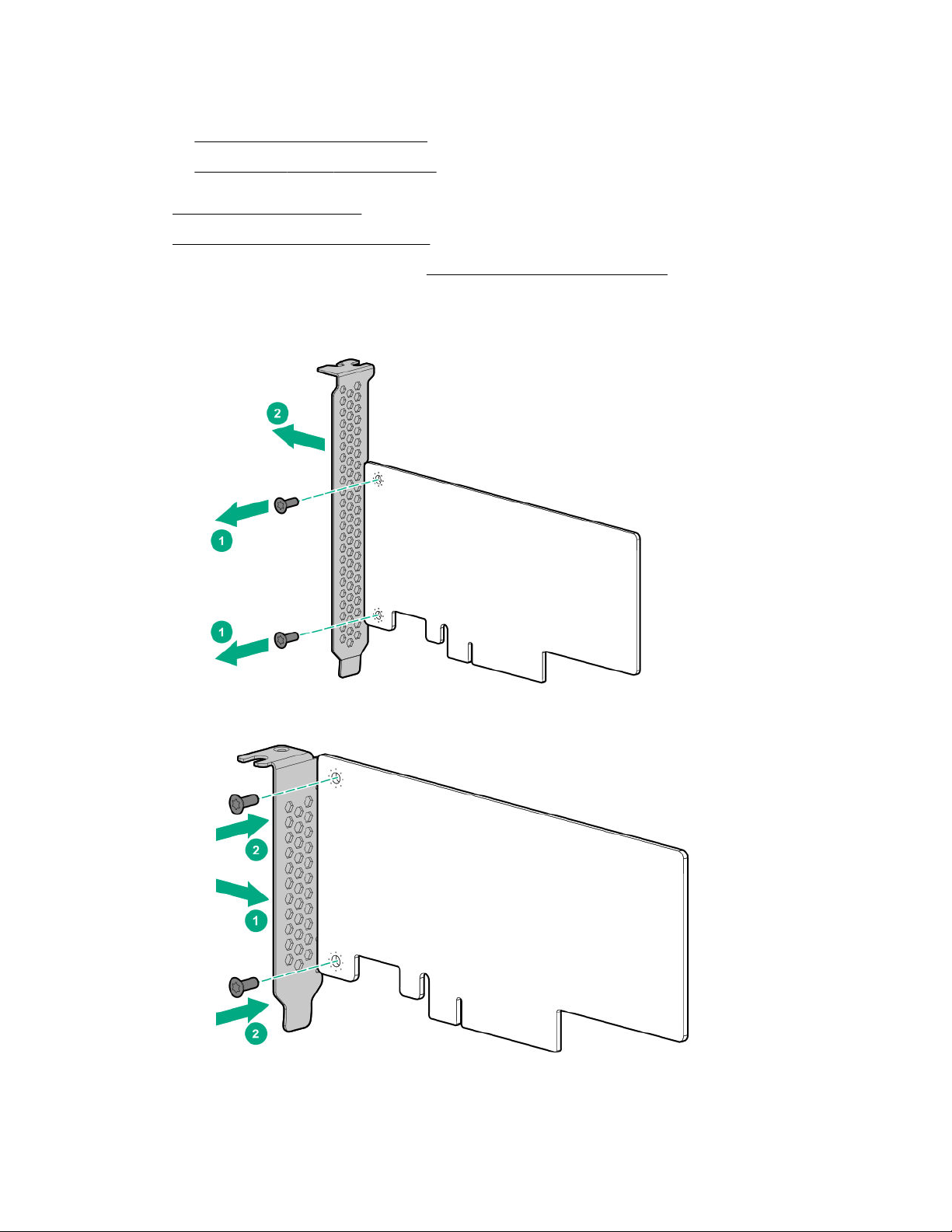
5. Disconnect all peripheral cables from the server.
6. Do one of the following:
• Extend the server from the rack.
• Remove the server from the rack.
7. Remove the access panel.
8. Remove the primary PCI riser cage.
9. Select the appropriate PCIe slot and remove the expansion slot blank.
10. If installing the option into slot 2 or slot 3, do the following:
a. Remove the full-height bracket from the M.2 SSD enablement board.
b. Install the half-height bracket onto the expansion board.
11. Install the expansion board.
76 Hardware options installation
Page 77
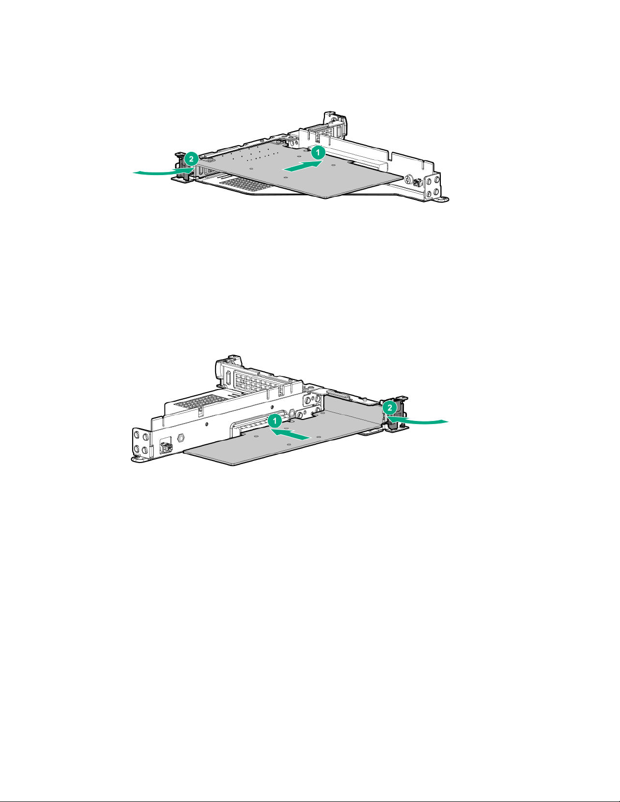
• Slot 1
• Slot 2
• Slot 3
Hardware options installation 77
Page 78
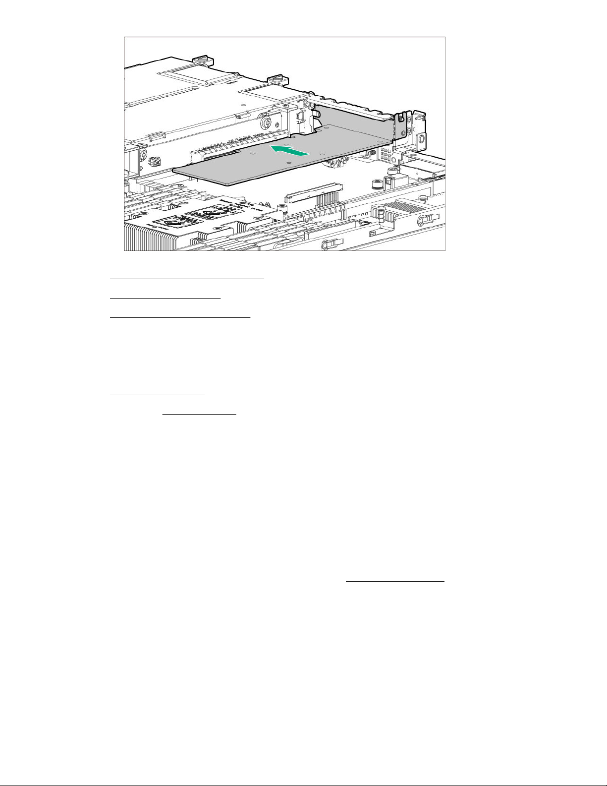
12. Install the primary PCI riser cage.
13. Install the access panel.
14. Install the server into the rack.
15. Connect all peripheral cables to the server.
16. Connect each power cord to the server.
17. Connect each power cord to the power source.
18. Power up the server.
19. If removed, install the bezel.
The installation is complete.
Storage controller options
The server supports the following storage controllers:
• For SATA drives only – Embedded HPE Smart Array S100i SR Gen10 Controller
• For SAS and SATA drives:
◦ Smart Array type-a modular controller
◦ Smart Array PCIe plug-in controller
For more information on PCIe slot descriptions, see PCIe slot description on page 15.
Installing a Smart Array modular controller
Prerequisites
Before you perform this procedure, make sure that you have the following items available:
78 Hardware options installation
Page 79

• Smart Array modular controller option
• Compatible controller cable option
• T-15 Torx screwdriver
Before you perform this procedure, perform the following steps:
1. Back up data on the system.
2. Close all applications.
3. Update the server firmware if it is not the latest revision.
4. Do one of the following:
• If the new Smart Array is the new boot device, install the device drivers.
• If the new Smart Array is not the new boot device, go to the next step.
5. Ensure that users are logged off and that all tasks are completed on the server.
CAUTION: In systems that use external data storage, be sure that the server is the first unit to be
powered down and the last to be powered back up. Taking this precaution ensures that the system
does not erroneously mark the drives as failed when the server is powered up.
Procedure
1. Observe the following alerts:
WARNING: To reduce the risk of personal injury from hot surfaces, allow the drives and the
internal system components to cool before touching them.
CAUTION: To prevent damage to electrical components, properly ground the server before
beginning any installation procedure. Improper grounding can cause electrostatic discharge.
2. Back up all server data.
3. If installed, remove the bezel.
4. Power down the server.
5. Remove all power:
a. Disconnect each power cord from the power source.
b. Disconnect each power cord from the server.
6. Disconnect all peripheral cables from the server.
7. Do one of the following:
• Extend the server from the rack.
• Remove the server from the rack.
8. If installed, remove the secondary PCI riser cage.
Hardware options installation 79
Page 80
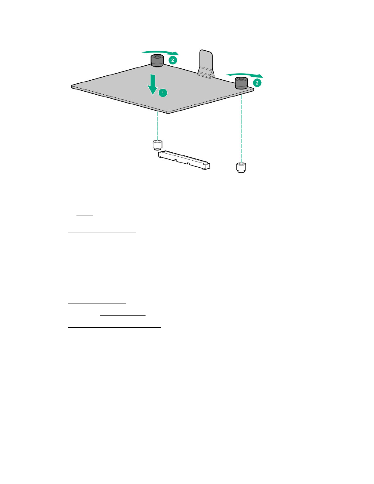
9. Remove the access panel.
10. Install the Smart Array modular controller.
11. Connect the cables to the backplane:
• 4 LFF
• 8 SFF
12. Install the access panel.
13. If removed, install the secondary PCI riser cage.
14. Install the server into the rack.
15. Connect all peripheral cables to the server.
16. Connect each power cord to the server.
17. Connect each power cord to the power source.
18. Power up the server.
19. If removed, install the bezel.
20. Configure the storage controller.
The installation is complete.
Installing a Smart Array PCIe plug-in controller
The Smart Array PCIe plug-in controller is only supported in PCIe slot 2.
Prerequisites
Before you perform this procedure, make sure that you have the following items available:
• Smart Array PCIe plug-in controller option kit
This kit includes:
80 Hardware options installation
Page 81
◦ Smart Array PCIe plug-in controller
◦ Controller backup power cable (required for Smart Storage Battery installation)
• Compatible controller cable option
• T-15 Torx screwdriver
Before you perform this procedure, perform the following steps:
1. Back up data on the system.
2. Close all applications.
3. Update the server firmware if it is not the latest revision.
4. Do one of the following:
• If the new Smart Array is the new boot device, install the device drivers.
• If the new Smart Array is not the new boot device, go to the next step.
5. Ensure that users are logged off and that all tasks are completed on the server.
Procedure
1. Observe the following alerts:
WARNING: To reduce the risk of personal injury from hot surfaces, allow the drives and the
internal system components to cool before touching them.
CAUTION: To prevent damage to electrical components, properly ground the server before
beginning any installation procedure. Improper grounding can cause electrostatic discharge.
2. Back up all server data.
3. If installed, remove the bezel.
4. Power down the server.
5. Remove all power:
a. Disconnect each power cord from the power source.
b. Disconnect each power cord from the server.
6. Disconnect all peripheral cables from the server.
7. Do one of the following:
• Extend the server from the rack.
• Remove the server from the rack.
8. Remove the access panel.
9. Remove the primary PCI riser cage.
10. Remove the expansion slot blank.
Hardware options installation 81
Page 82
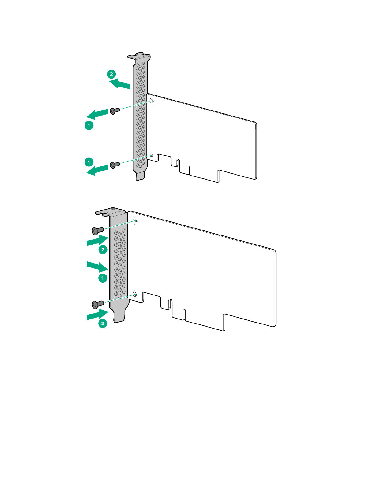
11. Do the following:
a. Remove the full-height bracket from the M.2 SSD enablement board.
b. Install the half-height bracket onto the expansion board.
12. Install the controller.
82 Hardware options installation
Page 83
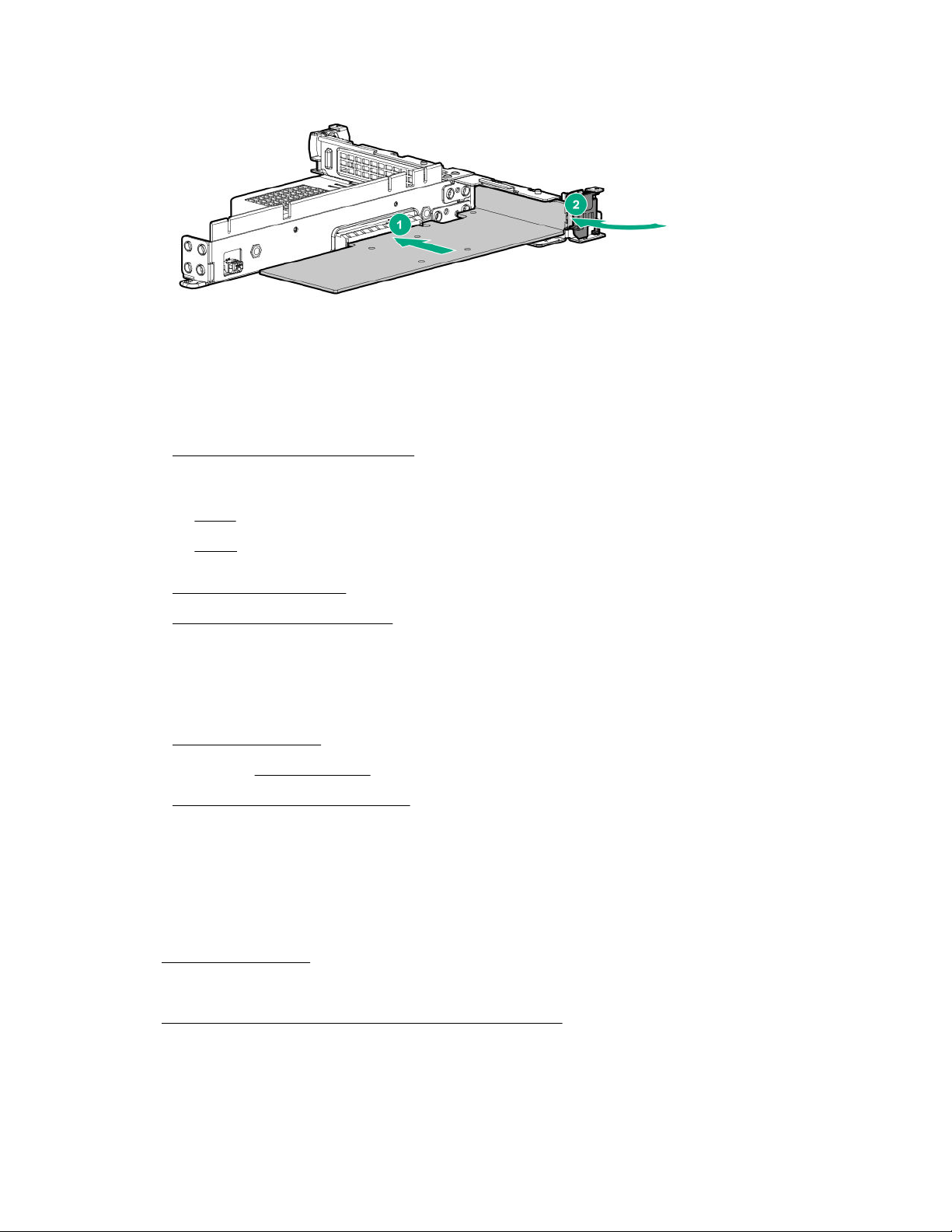
13. Connect the cables to the controller.
14. Install the primary PCI riser cage.
15. Connect the cables to the backplane:
• 4 LFF
• 8 SFF
16. Install the access panel.
17. Install the server into the rack.
18. Connect all peripheral cables to the server.
19. Connect each power cord to the server.
20. Connect each power cord to the power source.
21. Power up the server.
22. If removed, install the bezel.
23. Configure the storage controller.
The installation is complete.
Configuring an HPE Smart Array Gen10 controller
Procedure
1. Power up the server on page 36.
2. If you are running the server in UEFI Boot Mode, select the boot options.
3. Update the drive firmware if it is not the latest revision.
4. (Optional) If running the server in Legacy Boot Mode, set the controller as the boot controller.
5. (Optional) If running the server in Legacy Boot Mode, change the controller boot order.
Hardware options installation 83
Page 84
6. If the new controller is not the new boot device, install the device drivers.
7. If the controller firmware is not the latest version, use SPP to update it.
8. Use UEFI System Utilities or HPE Smart Storage Administrator (HPE SSA) to create arrays and
logical drives.
See the following resources for more information:
• SPP – See the product documentation in the information library:
http://www.hpe.com/info/spp/docs
• UEFI System Utilities or HPE Smart Storage Administrator – See the following guide in the information
library (http://www.hpe.com/info/smartstorage-docs):
HPE Smart Array SR Gen10 Configuration Guide
Processor heatsink assembly option
Processor cautions
CAUTION: To prevent possible server malfunction and damage to the equipment, multiprocessor
configurations must contain processors with the same part number.
CAUTION: If installing a processor with a faster speed, update the system ROM before installing
the processor.
To download firmware and view installation instructions, see the Hewlett Packard Enterprise
Support Center website.
CAUTION: THE CONTACTS ARE VERY FRAGILE AND EASILY DAMAGED. To avoid damage to
the socket or processor, do not touch the contacts.
CAUTION: To prevent mechanical damage or depositing oil on your hands or other contamination,
hold the heatsink only by the edge of its base plate. Do not touch the heatsink fins.
Installing a processor heatsink assembly
The server supports single-processor and dual processor operations.
Prerequisites
Before you perform this procedure, make sure that you have the following items available:
• Processor heatsink assembly option
• T-30 Torx screwdriver
Procedure
1. Identify the processor, heatsink, and socket module components.
2. Review the processor cautions.
3. Back up all server data.
84 Hardware options installation
Page 85
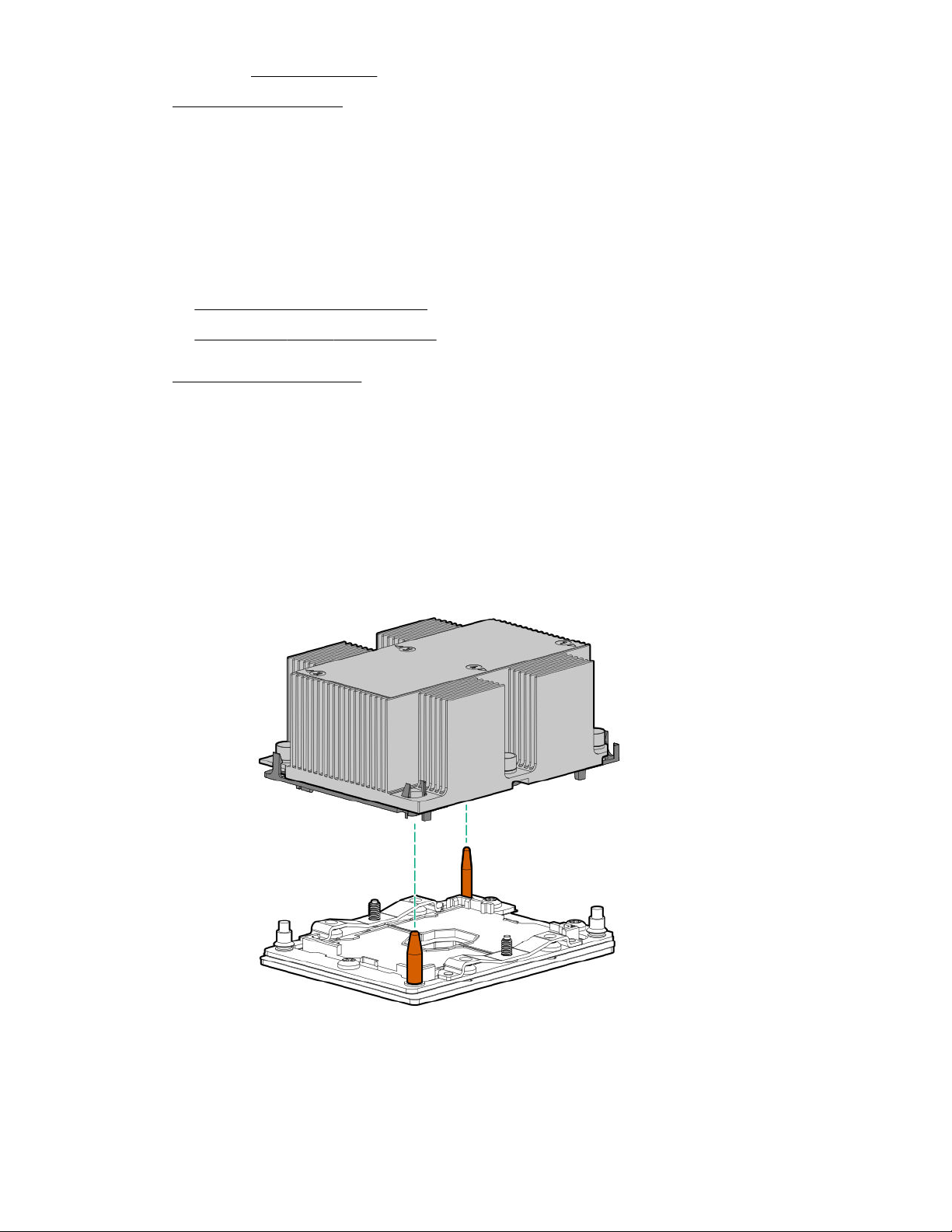
4. If installed, remove the bezel.
5. Power down the server.
6. Remove all power:
a. Disconnect each power cord from the power source.
b. Disconnect each power cord from the server.
7. Disconnect all peripheral cables from the server.
8. Do one of the following:
• Extend the server from the rack.
• Remove the server from the rack.
9. Remove the access panel.
10. Remove the dust cover from the processor socket you intend to upgrade.
11. Install the processor heatsink assembly:
a. Locate and align the Pin 1 indicator on the processor frame and the socket.
b. Align the processor heatsink assembly with the heatsink alignment posts and gently lower it down
until it sits evenly on the socket.
The heatsink alignment posts are keyed. The processor will only install one way.
A standard heatsink is shown, your heatsink might look different.
Hardware options installation 85
Page 86
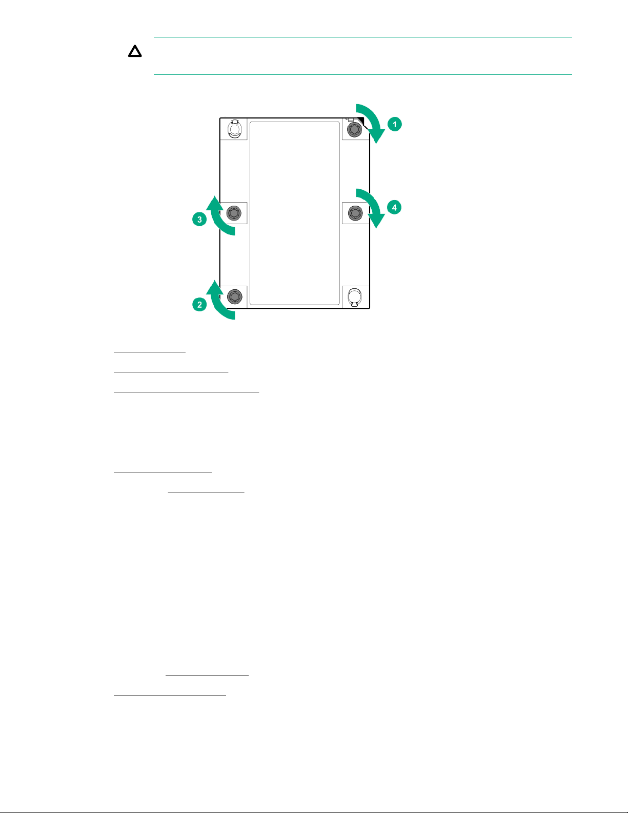
CAUTION: Be sure to tighten each heatsink nut fully in the order indicated. Otherwise, boot
failure or intermittent shutdowns might occur.
c. Using a T-30 Torx screwdriver, tighten the nuts until they stop.
12. Install the fans.
13. Install the access panel.
14. Install the server into the rack.
15. Connect all peripheral cables to the server.
16. Connect each power cord to the server.
17. Connect each power cord to the power source.
18. Power up the server.
19. If removed, install the bezel.
The installation is complete.
Installing the Chassis Intrusion Detection switch
Prerequisites
Before installing this option, be sure that you have the following:
The components included with the hardware option kit.
Procedure
1. Back up all server data.
2. If installed, remove the bezel.
3. Power down the server.
4. Remove all power:
86 Hardware options installation
Page 87
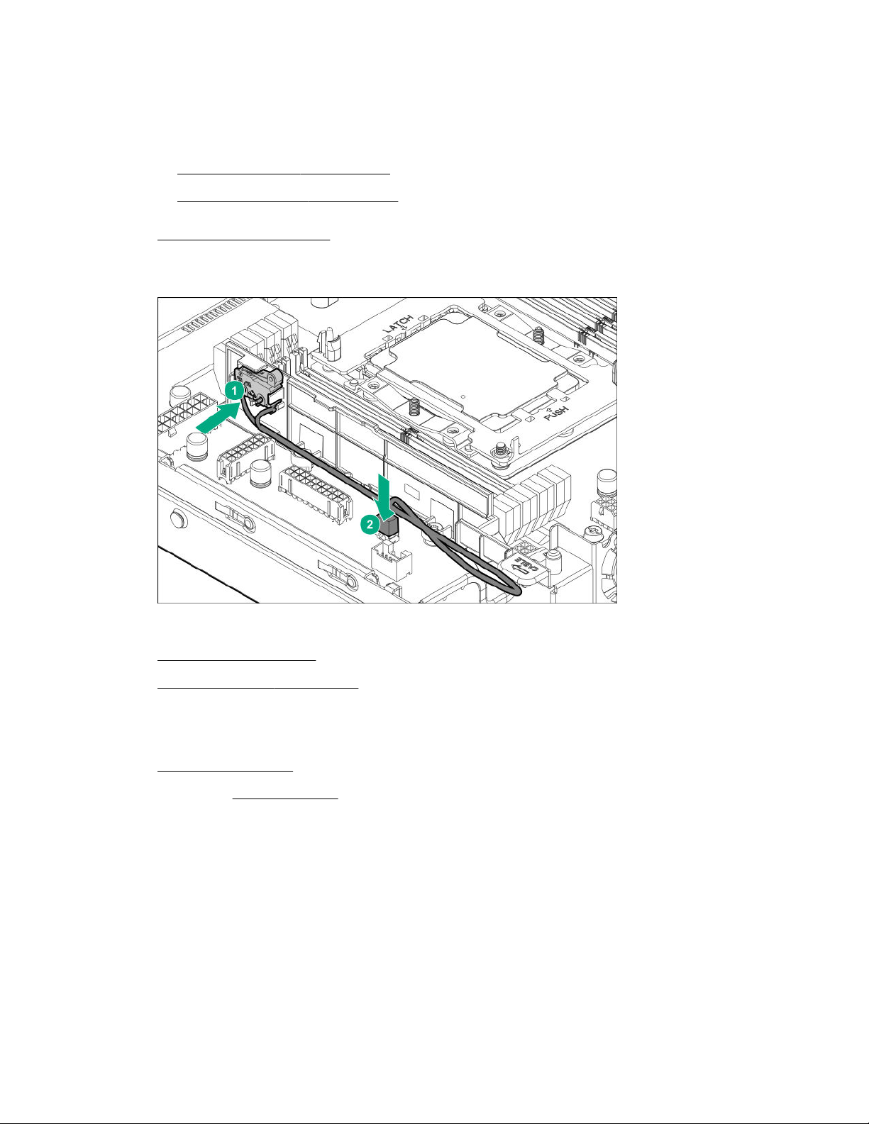
a. Disconnect each power cord from the power source.
b. Disconnect each power cord from the server.
5. Do one of the following:
a. Extend the server from the rack.
b. Remove the server from the rack.
6. Remove the access panel.
7. Install the chassis intruder detection switch onto the DIMM guard and connect the cable to the
system board.
8. Assemble the connector/cable harness pin openings to the alignment pegs on the DIMM guard.
9. Install the access panel.
10. Install the server into the rack.
11. Connect each power cord to the server.
12. Connect each power cord to the power source.
13. Power up the server.
14. If removed, install the bezel.
Smart Storage Battery option
The Smart Storage Battery is a centralized backup source and is required to back up the write cache
content onto flash memory on the HPE Smart Array P-class controllers in case of an unplanned server
power loss.
After the battery is installed, it might take up to two hours to charge. Controller features requiring backup
power are not enabled until the battery is capable of providing the backup power.
Hardware options installation 87
Page 88
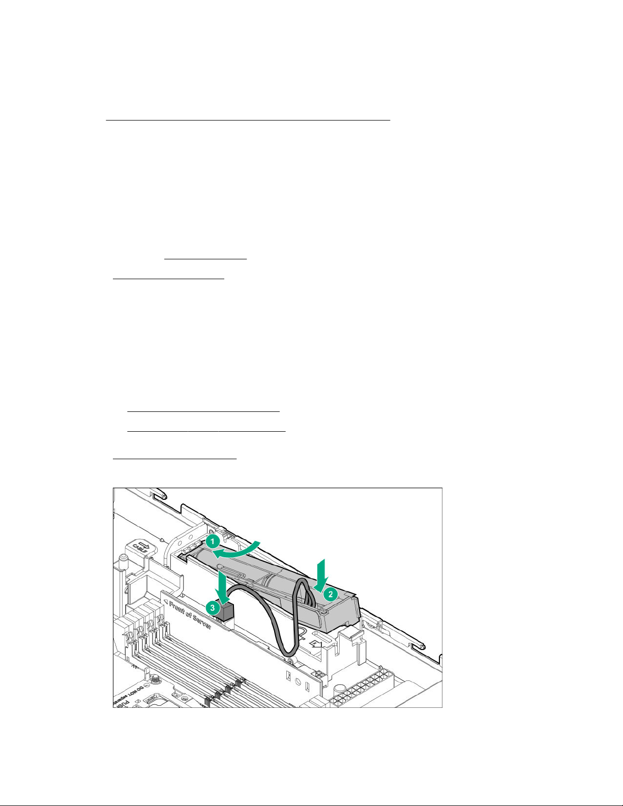
Installing the Smart Storage Battery
Prerequisites
Before you perform this procedure:
• Make sure that a Smart Array P-class controller is installed.
• Make sure that you have the following items available:
◦ Storage controller backup power cable (ships with the controller)
◦ Smart Storage Battery option
Procedure
1. Back up all server data.
2. If installed, remove the bezel.
3. Power down the server.
4. Remove all power:
a. Disconnect each power cord from the power source.
b. Disconnect each power cord from the server.
5. Disconnect all peripheral cables from the server.
6. Do one of the following:
•
Extend the server from the rack.
• Remove the server from the rack.
7. Remove the access panel.
8. Install the Smart Storage Battery and connect the cable.
88 Hardware options installation
Page 89

9. Connect the controller backup power cable.
10. Install the access panel.
11. Install the server into the rack.
12. Connect all peripheral cables to the server.
13. Connect each power cord to the server.
14. Connect each power cord to the power source.
15. Power up the server.
16. If removed, install the bezel.
The installation is complete.
M.2 SSD enablement option
The server supports the installation of one M.2 SSD enablement board. Each enablement board can
support two M.2 SSDs. The M.2 SSD enablement board is supported in the PCIe3 expansion slots 1–3.
Use the embedded HPE Smart Array S100i SR Gen10 Controller to manage the M.2 SATA SSDs. The
S100i SR Gen10 SW RAID support requires that the server boot mode be set to UEFI.
Installing the M.2 SSD enablement board
Prerequisites
Before you perform this procedure, make sure that you have the following items available:
• M.2 SSD enablement option
• M.2 SSD
• T-10 Torx screwdriver
• Phillips No. 1 screwdriver – required only if the M.2 SSD is not preinstalled on the enablement board.
If installing the M.2 SSD enablement board in slot 3, make sure that the processor 2 is installed.
Procedure
1. Back up all server data.
2. If installed, remove the bezel.
3. Power down the server.
4. Remove all power:
a. Disconnect each power cord from the power source.
b. Disconnect each power cord from the server.
5. Disconnect all peripheral cables from the server.
6. Do one of the following:
Hardware options installation 89
Page 90
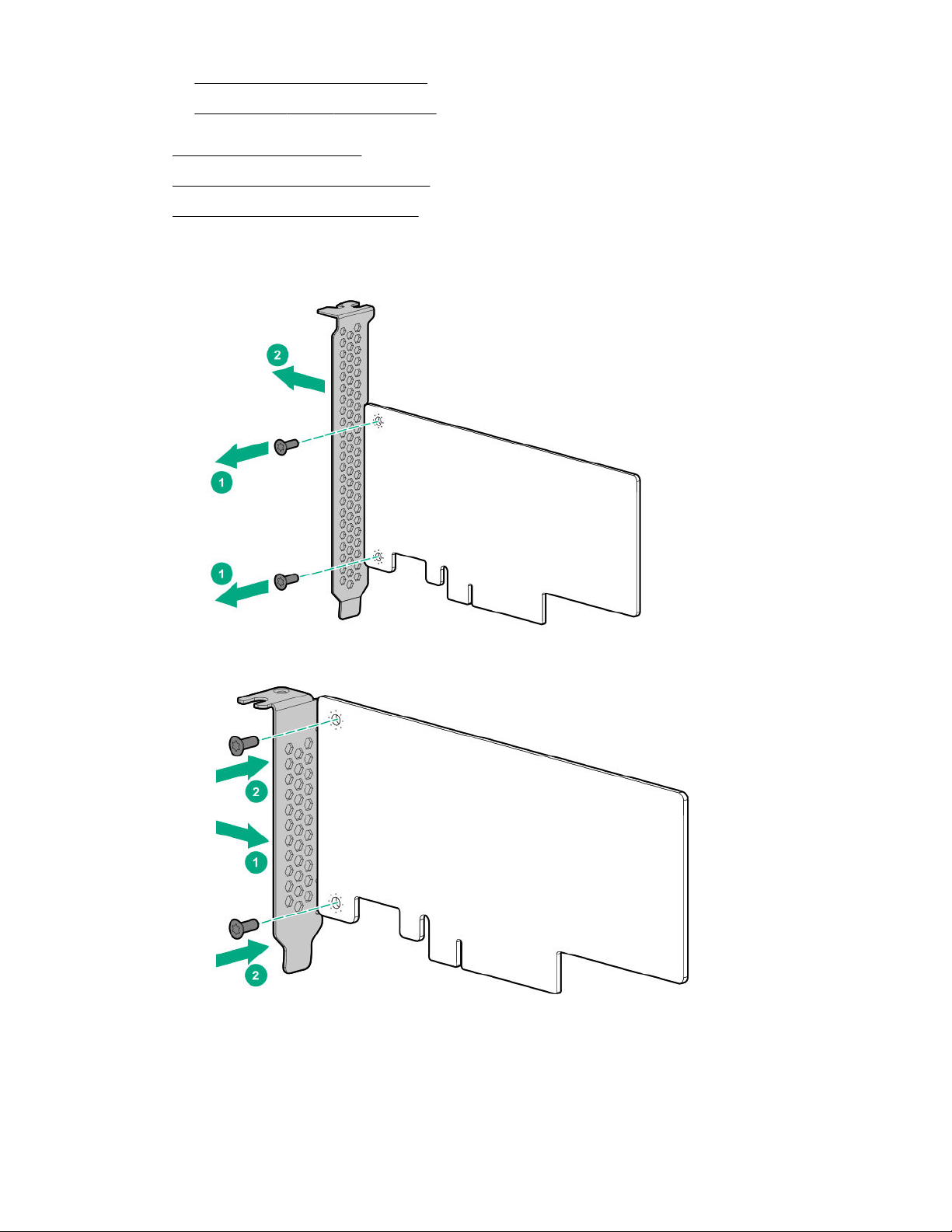
• Extend the server from the rack.
• Remove the server from the rack.
7. Remove the access panel.
8. Remove the primary PCI riser cage.
9. Remove the expansion slot blank.
10. If installing the option into slot 2 or slot 3, do the following:
a. Remove the full-height bracket from the M.2 SSD enablement board.
b. Install the half-height bracket onto the expansion board.
11. If the SSD is not preinstalled on the M.2 SSD enablement board, do the following:
If only one SSD is being installed, install the SSD in port 1.
90 Hardware options installation
Page 91
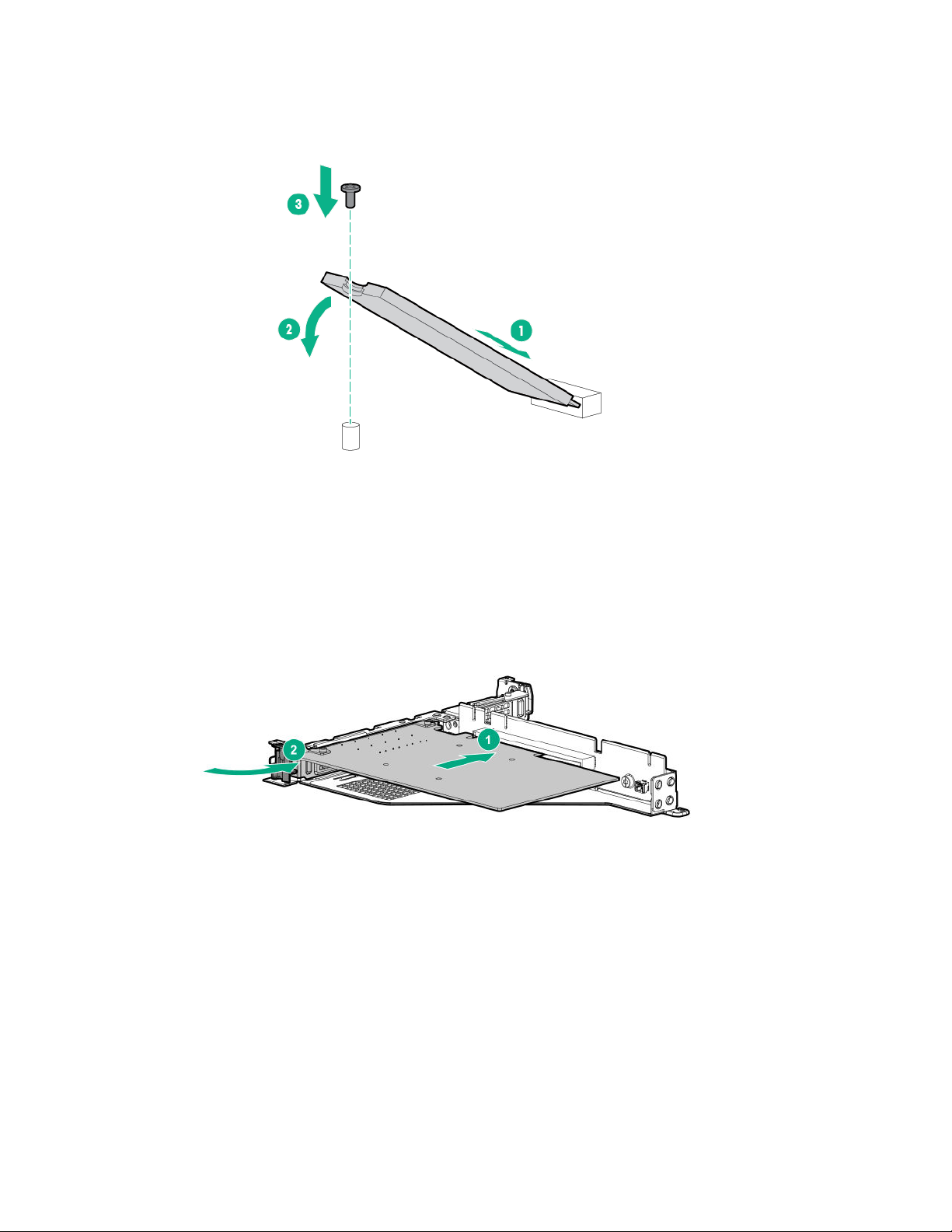
a. Insert the SSD into the M.2 slot at a 45° angle.
b. Carefully press the SSD down to the horizontal position.
c. Install the SSD mounting screw.
d. If you are installing a second SSD, repeat steps a–c.
12. Install the M.2 SSD enablement board with installed SSD modules into the PCI riser cage, and then
connect the SATA cables to the enablement board.
• Slot 1
• Slot 2
Hardware options installation 91
Page 92
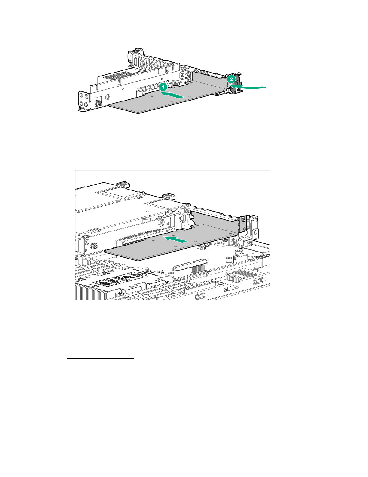
• Slot 3
If installing the M.2 SSD enablement board in slot 3, a type-a modular storage controller is not
supported in the server.
13. Install the primary PCI riser cage.
14. Route and connect the cables.
15. Install the access panel.
16. Install the server into the rack.
17. Connect all peripheral cables to the server.
18. Connect each power cord to the server.
19. Connect each power cord to the power source.
92 Hardware options installation
Page 93
20. Power up the server.
21. If removed, install the bezel.
The installation is complete.
To configure the M.2 SATA SSDs, see the HPE Smart Array SR Gen10 Configuration Guide at the
Hewlett Packard Enterprise website.
HPE Trusted Platform Module 2.0 Gen10 option
Overview
Use these instructions to install and enable an HPE TPM 2.0 Gen10 Kit in a supported server. This option
is not supported on Gen9 and earlier servers.
This procedure includes three sections:
1. Installing the Trusted Platform Module board.
2. Enabling the Trusted Platform Module.
3. Retaining the recovery key/password.
HPE TPM 2.0 installation is supported with specific operating system support such as Microsoft
Windows Server® 2012 R2 and later. For more information about operating system support, see the
product QuickSpecs on the Hewlett Packard Enterprise website (http://www.hpe.com/info/qs). For more
information about Microsoft® Windows® BitLocker Drive Encryption feature, see the Microsoft website
(http://www.microsoft.com).
CAUTION: If the TPM is removed from the original server and powered up on a different server,
data stored in the TPM including keys will be erased.
IMPORTANT: In UEFI Boot Mode, the HPE TPM 2.0 Gen10 Kit can be configured to operate as
TPM 2.0 (default) or TPM 1.2 on a supported server. In Legacy Boot Mode, the configuration can be
changed between TPM 1.2 and TPM 2.0, but only TPM 1.2 operation is supported.
HPE Trusted Platform Module 2.0 Guidelines
CAUTION: Always observe the guidelines in this document. Failure to follow these guidelines can
cause hardware damage or halt data access.
Hewlett Packard Enterprise SPECIAL REMINDER: Before enabling TPM functionality on this system,
you must ensure that your intended use of TPM complies with relevant local laws, regulations and
policies, and approvals or licenses must be obtained if applicable.
For any compliance issues arising from your operation/usage of TPM which violates the above mentioned
requirement, you shall bear all the liabilities wholly and solely. Hewlett Packard Enterprise will not be
responsible for any related liabilities.
®
When installing or replacing a TPM, observe the following guidelines:
Hardware options installation 93
Page 94
• Do not remove an installed TPM. Once installed, the TPM becomes a permanent part of the system
board.
• When installing or replacing hardware, Hewlett Packard Enterprise service providers cannot enable
the TPM or the encryption technology. For security reasons, only the customer can enable these
features.
• When returning a system board for service replacement, do not remove the TPM from the system
board. When requested, Hewlett Packard Enterprise Service provides a TPM with the spare system
board.
• Any attempt to remove the cover of an installed TPM from the system board can damage the TPM
cover, the TPM, and the system board.
• If the TPM is removed from the original server and powered up on a different server, data stored in the
TPM including keys will be erased.
• When using BitLocker, always retain the recovery key/password. The recovery key/password is
required to complete Recovery Mode after BitLocker detects a possible compromise of system
integrity.
• Hewlett Packard Enterprise is not liable for blocked data access caused by improper TPM use. For
operating instructions, see the TPM documentation or the encryption technology feature
documentation provided by the operating system.
Installing and enabling the HPE TPM 2.0 Gen10 Kit
Installing the Trusted Platform Module board
Preparing the server for installation
Procedure
1. Observe the following warnings:
WARNING: The front panel Power On/Standby button does not shut off system power. Portions
of the power supply and some internal circuitry remain active until AC power is removed.
To reduce the risk of personal injury, electric shock, or damage to the equipment, remove power
from the server:
For rack and tower servers, remove the power cord.
For server blades and compute modules, remove the server blade or compute module from the
enclosure.
WARNING: To reduce the risk of personal injury from hot surfaces, allow the drives and the
internal system components to cool before touching them.
2. Update the system ROM.
Locate and download the latest ROM version from the Hewlett Packard Enterprise Support Center
website. Follow the instructions on the website to update the system ROM.
3. Power down the server (Powering down the server on page 36).
94 Hardware options installation
Page 95
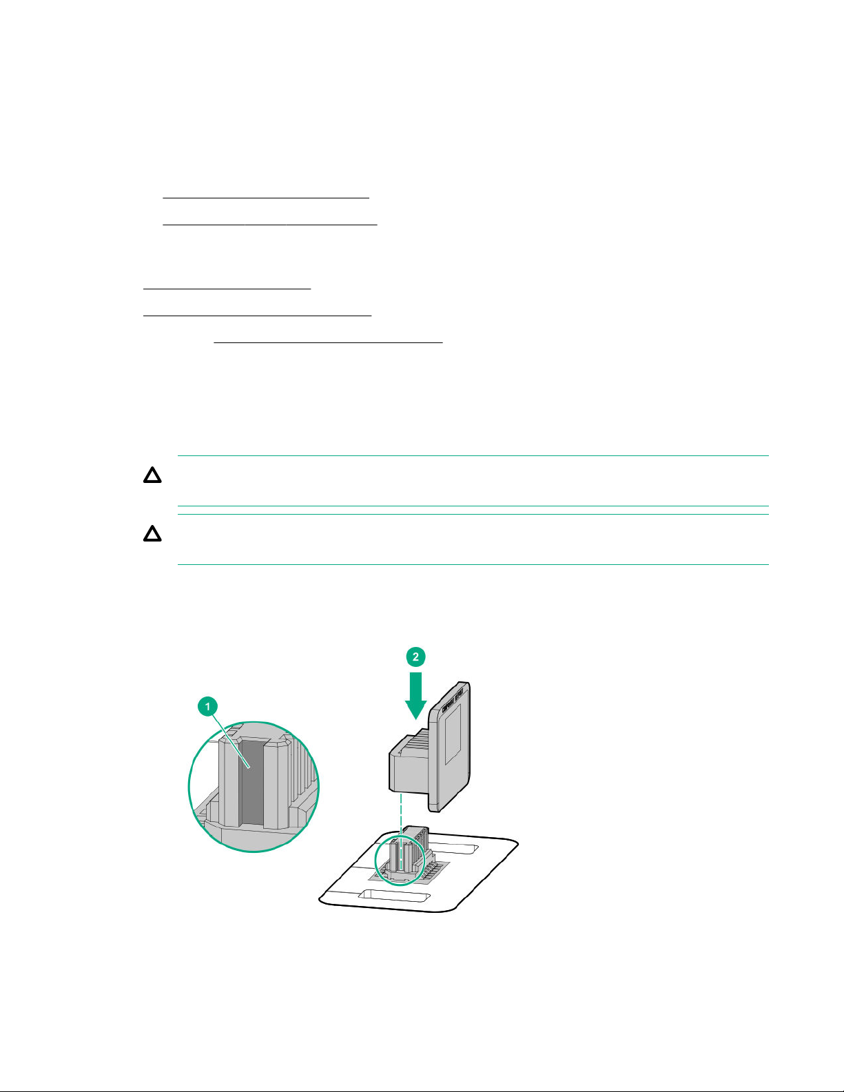
4. Remove all power:
a. Disconnect each power cord from the power source.
b. Disconnect each power cord from the server.
5. Do one of the following:
• Extend the server from the rack.
• Remove the server from the rack.
6. Place the server on a flat, level work surface.
7. Remove the access panel.
8. Remove the primary PCI riser cage.
9. Proceed to Installing the TPM board and cover on page 95.
Installing the TPM board and cover
Procedure
1. Observe the following alerts:
CAUTION: If the TPM is removed from the original server and powered up on a different server,
data stored in the TPM including keys will be erased.
CAUTION: The TPM is keyed to install only in the orientation shown. Any attempt to install the
TPM in a different orientation might result in damage to the TPM or system board.
2. Align the TPM board with the key on the connector, and then install the TPM board. To seat the board,
press the TPM board firmly into the connector. To locate the TPM connector on the system board, see
the server label on the access panel.
3. Install the TPM cover:
Hardware options installation 95
Page 96
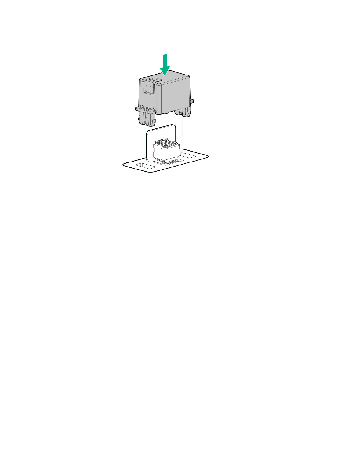
a. Line up the tabs on the cover with the openings on either side of the TPM connector.
b. To snap the cover into place, firmly press straight down on the middle of the cover.
4. Proceed to Preparing the server for operation on page 96.
Preparing the server for operation
Procedure
1. Install any options or cables previously removed to access the TPM connector.
2. Install the access panel.
3. Do one of the following:
a. Install the server in the rack, if necessary.
b. Install the server in the enclosure.
4. Power up the server.
a. Connect the power cords (rack and tower servers).
b. Press the Power On/Standby button.
Enabling the Trusted Platform Module
When enabling the Trusted Platform module, observe the following guidelines:
• By default, the Trusted Platform Module is enabled as TPM 2.0 when the server is powered on after
installing it.
• In UEFI Boot Mode, the Trusted Platform Module can be configured to operate as TPM 2.0 or TPM
1.2.
• In Legacy Boot Mode, the Trusted Platform Module configuration can be changed between TPM 1.2
and TPM 2.0, but only TPM 1.2 operation is supported.
96 Hardware options installation
Page 97

Enabling the Trusted Platform Module as TPM 2.0
Procedure
1. During the server startup sequence, press the F9 key to access System Utilities.
2. From the System Utilities screen, select System Configuration > BIOS/Platform Configuration
(RBSU) > Server Security > Trusted Platform Module options.
3. Verify the following:
• "Current TPM Type" is set to TPM 2.0.
• "Current TPM State" is set to Present and Enabled.
• "TPM Visibility" is set to Visible.
4. If changes were made in the previous step, press the F10 key to save your selection.
5. If F10 was pressed in the previous step, do one of the following:
• If in graphical mode, click Yes.
• If in text mode, press the Y key.
6. Press the ESC key to exit System Utilities.
7. If changes were made and saved, the server prompts for reboot request. Press the Enter key to
confirm reboot.
If the following actions were performed, the server reboots a second time without user input. During
this reboot, the TPM setting becomes effective.
• Changing from TPM 1.2 and TPM 2.0
• Changing TPM bus from FIFO to CRB
• Enabling or disabling TPM
• Clearing the TPM
8. Enable TPM functionality in the OS, such as Microsoft Windows BitLocker or measured boot.
For more information, see the Microsoft website.
Enabling the Trusted Platform Module as TPM 1.2
Procedure
1. During the server startup sequence, press the F9 key to access System Utilities.
2. From the System Utilities screen select System Configuration > BIOS/Platform Configuration
(RBSU) > Server Security > Trusted Platform Module options.
3. Change the "TPM Mode Switch Operation" to TPM 1.2.
4. Verify "TPM Visibility" is Visible.
5. Press the F10 key to save your selection.
Hardware options installation 97
Page 98

6. When prompted to save the change in System Utilities, do one of the following:
• If in graphical mode, click Yes.
• If in text mode, press the Y key.
7. Press the ESC key to exit System Utilities.
The server reboots a second time without user input. During this reboot, the TPM setting becomes
effective.
8. Enable TPM functionality in the OS, such as Microsoft Windows BitLocker or measured boot.
For more information, see the Microsoft website.
Retaining the recovery key/password
The recovery key/password is generated during BitLocker setup, and can be saved and printed after
BitLocker is enabled. When using BitLocker, always retain the recovery key/password. The recovery key/
password is required to enter Recovery Mode after BitLocker detects a possible compromise of system
integrity.
To help ensure maximum security, observe the following guidelines when retaining the recovery key/
password:
• Always store the recovery key/password in multiple locations.
• Always store copies of the recovery key/password away from the server.
• Do not save the recovery key/password on the encrypted hard drive.
98 Hardware options installation
Page 99

Cabling
Cabling guidelines
The cable colors in the cabling diagrams used in this chapter are for illustration purposes only. Most of the
server cables are black.
Observe the following guidelines when working with server cables.
Before connecting cables
• Note the port labels on the PCA components. Not all of these components are used by all servers:
◦ System board ports
◦ Drive and power supply backplane ports
◦ Expansion board ports (controllers, adapters, expanders, risers, and similar boards)
• Note the label near each cable connector. This label indicates the destination port for the cable
connector.
• Some data cables are pre-bent. Do not unbend or manipulate the cables.
• To prevent mechanical damage or depositing oil that is present on your hands, and other
contamination, do not touch the ends of the connectors.
When connecting cables
• Before connecting a cable to a port, lay the cable in place to verify the length of the cable.
• Use the internal cable management features to properly route and secure the cables.
• When routing cables, be sure that the cables are not in a position where they can be pinched or
crimped.
• Avoid tight bend radii to prevent damaging the internal wires of a power cord or a server cable. Never
bend power cords and server cables tight enough to cause a crease in the sheathing.
• Make sure that the excess length of cables are properly secured to avoid excess bends, interference
issues, and airflow restriction.
• To prevent component damage and potential signal interference, make sure that all cables are in their
appropriate routing position before installing a new component and before closing up the server after
hardware installation/maintenance.
When disconnecting cables
• Grip the body of the cable connector. Do not pull on the cable itself because this action can damage
the internal wires of the cable or the pins on the port.
• If a cable does not disconnect easily, check for any release latch that must be pressed to disconnect
the cable.
Cabling 99
Page 100
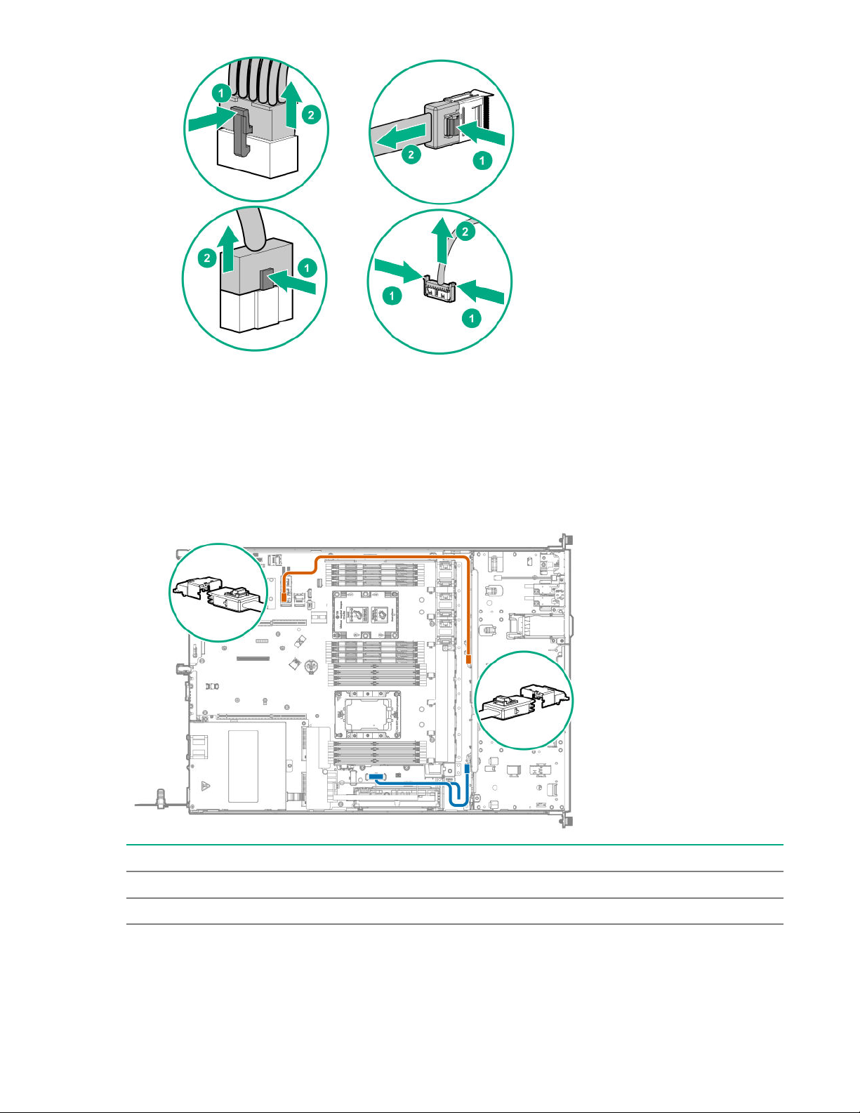
• Remove cables that are no longer being used. Retaining them inside the server can restrict airflow. If
you intend to use the removed cables later, label and store them for future use.
Four-bay LFF drive model cabling
Four-bay LFF drive backplane cabling
Connected to the system board
Cable Color Description
Orange Mini-SAS cable
Blue Drive backplane power cable
Connected to a type-a modular Smart Array controller
100 Cabling
 Loading...