

Page 1
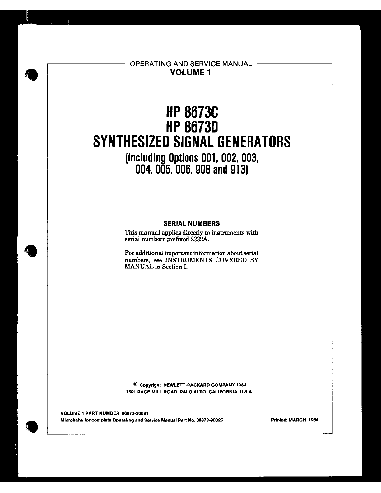
OPERATING AND SERVICE MANUAL
VOLUME 1
HP 8673C
HP 86730
SYNTHESIZED SIGNAL GENERATORS
(Including Options 001,002,003,
004,005,006,908 and 913)
SERIAL NUMBERS
This manual applies directly to instruments with
serial numbers prefixed 2332A.
For additional important information about serial
numbers, see INSTRUMENTS COVERED BY
MANUAL in Section I.
@ Copyright HEWLE’IT-PACKARD COMPANY lgS4
,601 PAGE MILL ROAD, PALO ALTO, CALIFORNIA, U.S.A.
VOLUME 1 PART NUMBER 08673-w1021
Mlcrollche lor cornplato Operating and Service Manual Part No. 08673-80025
PrInted: MARCH lgS4
Page 2

COPYRIGHT AND DISCLAIMER NOTICE
Copyright - Agilent Technologies, Inc. Reproduced with the permission of Agilent
Technologies Inc. Agilent Technologies, Inc. makes no warranty of any kind with regard
to this material including, but not limited to, the implied warranties of merchantability
and fitness for a particular purpose. Agilent Technologies, Inc. is not liable for errors
contained herein or for incidental or consequential damages in connection with the
furnishing, performance, or use of this material or data.
Page 3
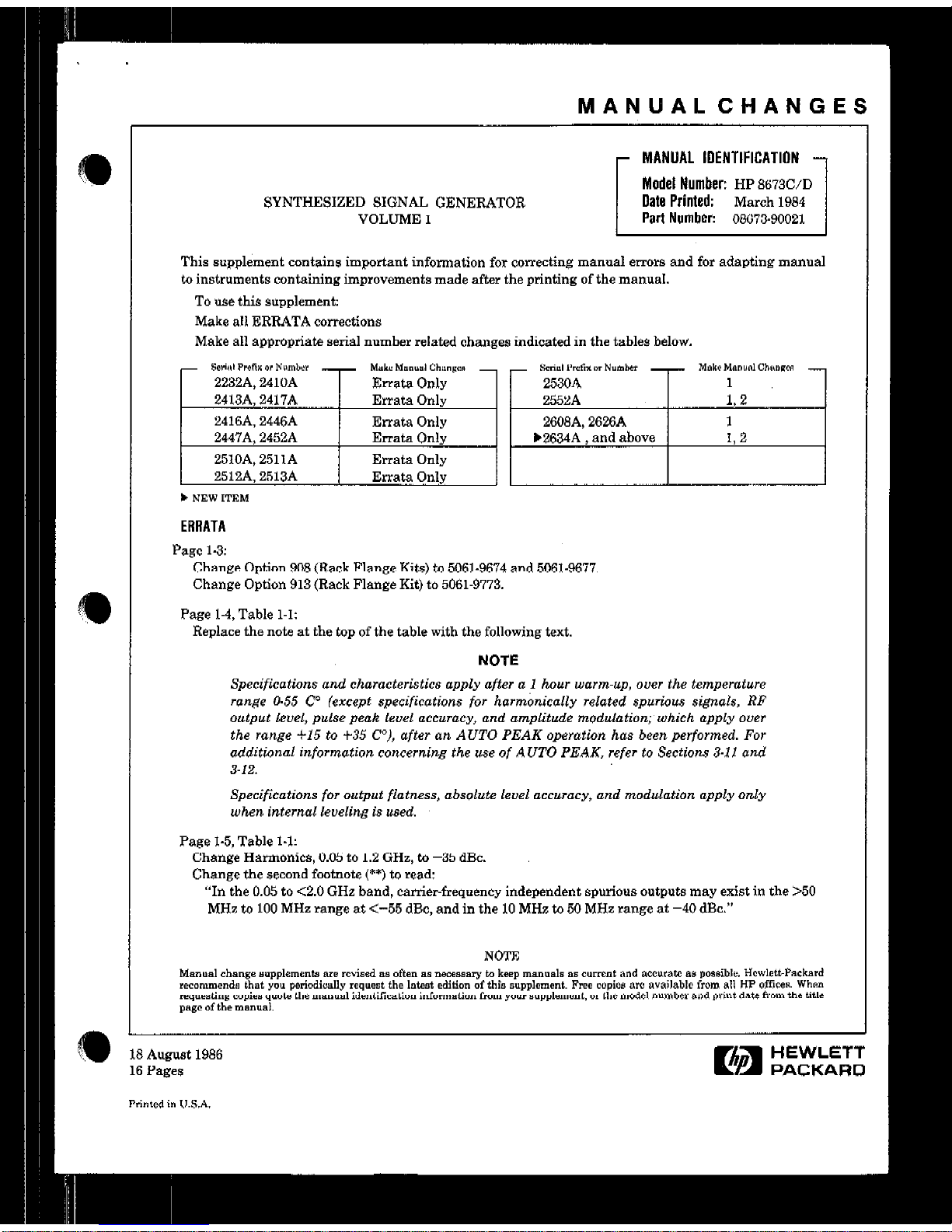
MANUALCHANGES
SYNTHESIZED SIGNAL GENERATOR
VOLUME 1
MANUAL IDENTIFICATION
Model Number:
HP 867X/D
Date Printed:
March 1984
Part Number:
08673-90021
1
This supplement contains important information for correcting manual error8 and for adapting manual
to
instruments
containing improvements made after the printing of the manual.
To use this supplement:
Make all ERRATA corrections
Make all appropriate serial number related changes indicated in the tables below.
- Somd ProfiX “” Nwnk - Make Munu.l Chmcl” - - Srnul ,‘.A* 0. Nvmllcr - Muke Mununl Chll”llCR 2232A, 2410A
Errata Only 2530A
1
2413A, 2417A Errata Only 2552A
L2
2416A. 2446A
Erratn Only
2603A, 2626A 1
2447A, 2452A Errata Only
)2634A , and above 1,2
2510A, 2511A Errata Only
2512A. 2513A
Errata Only
b NEW ITEM
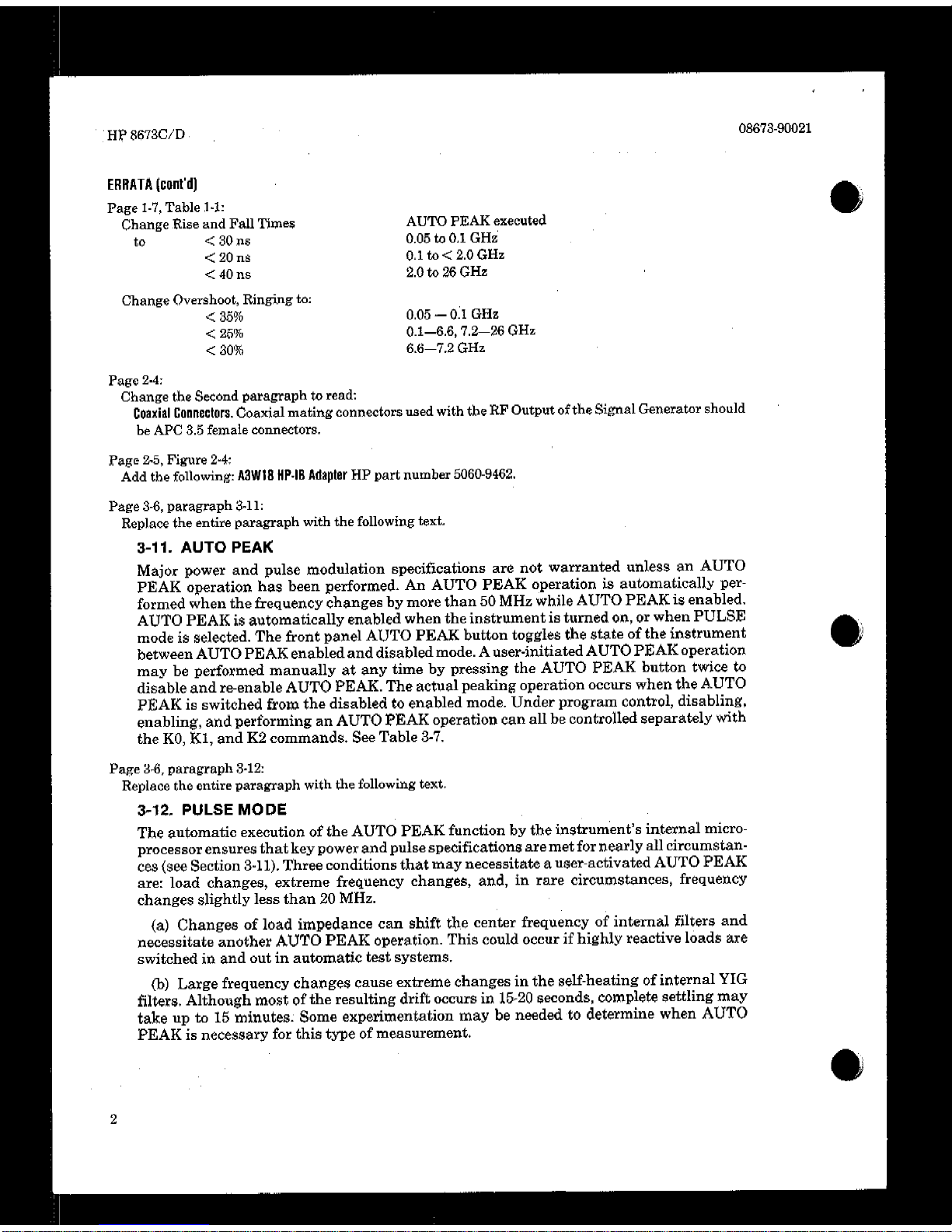
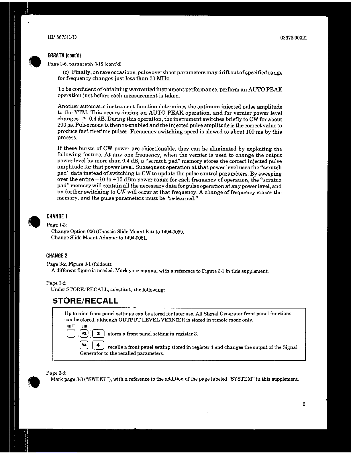
ERRATA
Pago 1-3:
Change Option 908 (Hack Flangs Kits) to
5061-9674 and 5061-9677.
Change Option 913 (Rack Flange Kit) to 5061-9773.
Page 1-4, Table 1-l:
Replace the note at the top of the table with the following text.
NOTE
Specifications and characteristics apply after a 1 hour warm-up, over the temperature
range 0.55 ‘2 (except specifications for harmonically related spurious signals, RP
output lcuel, puke peak level accuracy, and amplitude modulatimqwhich apply ouer
the range 415 to f35 CO)), after an AUTO PEAK operation has been performed. For
additional information concerning the use of AUTO PEAK, refer to Sections 3.11 and
3-12.
Specifications for output flatness, absolute level accuracy, and modulation apply only
when internal leveling is used.
Page 1-5, Table 1-l:
Change Harmonics, 0.05 to 1.2 GHz, to -35 dBc.
Change the second footnote (**) to read:
“In the 0.05 to <2.0 GHz band, carrier-frequency independent spurious outputs may exist in the >50
MHz to 100 MHz range at <-55 dBc, and in the 10 MHz to 50 MHz range
at
-40 dBc.”
; August
Pages
MCd in I,.
1986
Ea
HEWLETT
PACKARD
Page 4
Page 5
Page 6

Page 7
Page 8
Page 9
Page 10
Page 11
Page 12
Page 13
Page 14
Page 15
Page 16
Page 17

Page 18
Page 19
Page 20
Page 21
HP 8673C/D COntents
CONTENTS
Sectlon
I
GENERAL INFORMATION
Page
Introduction ...................................... 1-l
Specifications .................................... 1-l
Safety Considerations ............................ 1-1
Instrumenta Covered by this Manual .............. 1-I
Manual Changes Supplement ..................... 1-I
Deecxiption.......................................1.2
Options .......................................... 1.2
Electrical Options ..............................
1-2
Mechanical Options ............................ 1-3
Accessories Supplied ............................. l-3
Equipment Required but not Supplied ............. 1-3
Electrical Equipment Available ................... 1-3
Recommended ‘I&t Equipment .................... l-3
Section II
INSTALLATION
Introduction ..................................... .2-l
Initial Inspection ................................ .2-l
Preparation for Use ............................. ,2-l
Power Requirements. .......................... .2-l
Line Voltage and Fuse Selectmn ................ 2-I
PowerCables................................... -I
HP.IB Address Selection ........................ %2
Interconnections ............................... %3
Mating Connectors ............................. %3
operating Environment ........................ %4
Bench Operation ............................... %4
Rack Mounting ................................ .2-4
Storage and Shipment ........................... .2-4
Environment .................................. .2.4
Packaging ................................... ..2 -4
Section Ill
OPERATION
Introduction......................................a- 1
Operating Characteristics ..................... .3-l
Local Operation ................................ Sl
Remote Operation ............................. .51
Operator’sChecks..............................& 1
Operator’s Maintenance ....................... .51
General Instructions ............................. .3-4
nm-On
....................................... .3-4
Frequency Standard Selection ................. .3-4
Additional Operating Information ............... .3-6
AutoPeak........................................3 -6
Pulse Mode. ..................................... .3-6
ALC (Automatic Level Control) .................. .3-6
SweepMode...................................... -6
Operator’s Checks .............................. ,514
Basic Functional Checks ..................... ,914
HP-IB Functional Checks ..................... ,523
Page
Remote Operation, Auxiliary Control ............. $30
Remote and Local
Messages
and the
AUX Input Lines ............................. ,3-30
AUX Output Lines ........................... .3-30
R&mote Operation HewlettiPackard
Interface Bus .................................. .3-31
HP-IB Compatibility ......................... .3-31
Remote Mode ................................. ,331
Local Mode,, ................................. ,331
Addressing .................................... $33
Turn-on Default Condition .................... .3-34
Data Messages ............................... ,834
D’ 1 wp ays ...................................... 834
Output Level ................................. .3-34
Receiving Data Messages ..................... ,534
Sending the Data
Meeeage .................... .3-35
Receiving
the Clear Message .................. .3-38
Receiving the Trigger Message ................ .3-38
Receiving the Remote Message. ............... .3-38
Receiving the Local Message. ................. .3-38
Receiving the Local Lockout Message ......... .3-38
Receiting the Clear Lockout/Set Local
Message .................................... .3-38
Receiving the Pass Control Message .......... .3-39
Sending the Require Service Message ......... .3-39
Sending the Statue Byte Mesaage ............. .3-39
Clearing the Statue
Byte ...................... .3-39
Sending the Status Bit Message ............... .3-40
Receiving the Abort Message ................. .3-40
Sectlon IV
PERFORMANCE TESTS, Part 1
Introduction .................................... 4-1
Equipment Required ............................ 4-1
Performance Test Record ........................ 4-1
Test Procedures ................................. 4-1
Operation Verification .......................... 4-1
Turn-on Checks ................................. 4-2
Frequency Range and Resolution ................ 4-3
output Level .................................... 4-5
Frequency and Amplitude Modulation .......... 4.13
Pulse Modulation .............................. 4-16
Section IV, Pm-l 2
PERFORMANCE TESTS, Part 2,
and
Sections V, VI, VII and VIII
ADJUSTMENTS
REPLACEABLE PARTS
MANUAL CHANGES
SERVICE
These sections are bound separately in Volume 2 with a
separate table of contents.
Page 22
Contents
Figure
ilST OF ILLUSTRATIONS
Page
Figure
HP 8673WD
Page
l-l.
1-2.
2-l.
22.
2-3.
2-4.
2-6.
n
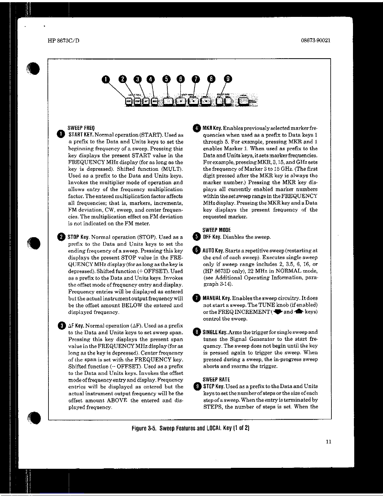
1 51.
3-2.
3-3.
84.
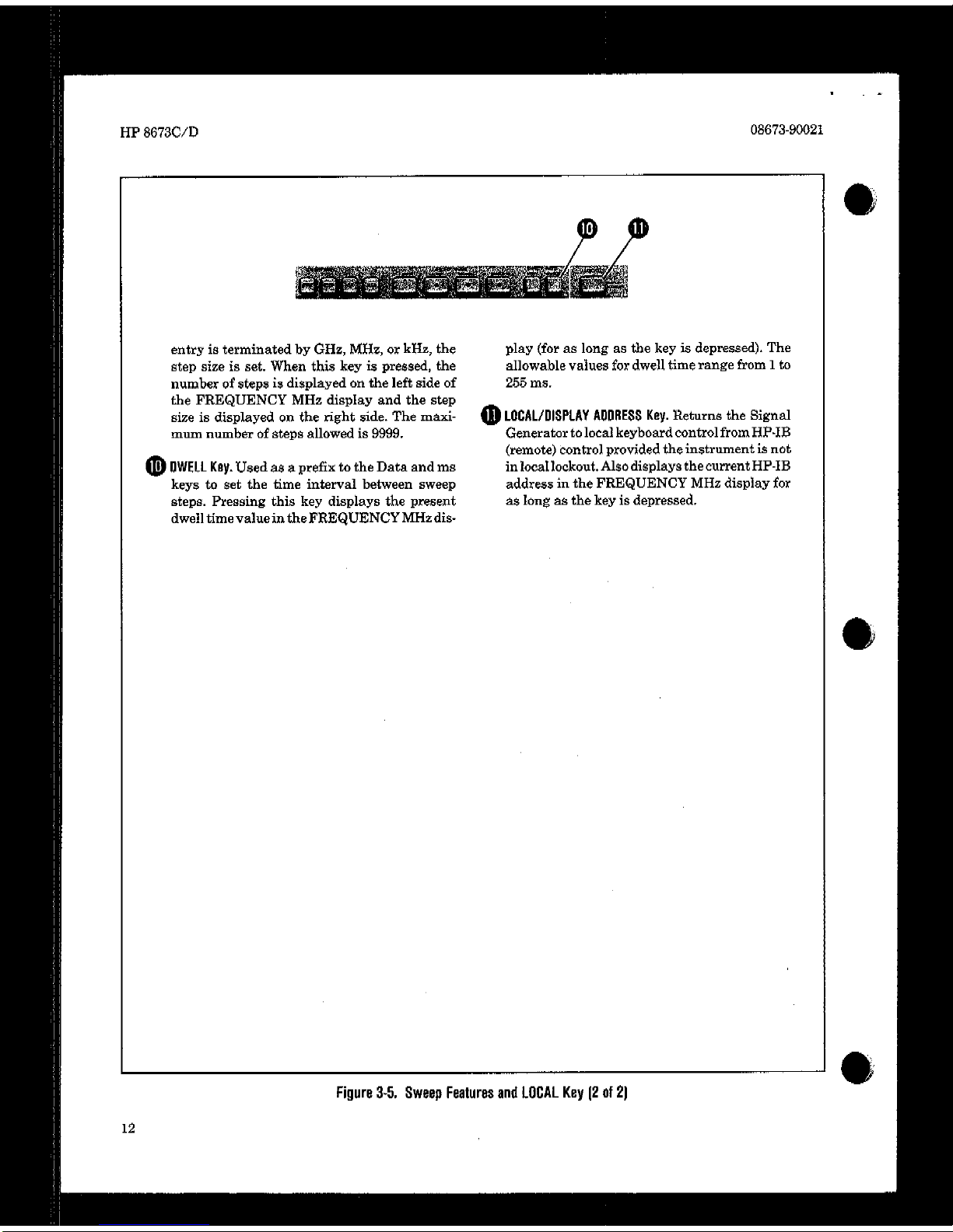
3-5.
3-6.
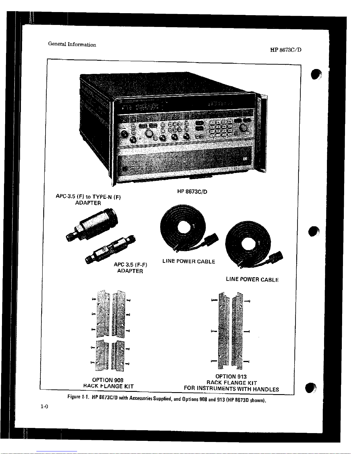
HP 8673C/D Accessories Supplied,
and Options 908 and 913
................. .1-O
Special Interconned Cable ................
. l-17
Line Voltage and Fuee Selection ............
.%2
Power Cable and Mains Plug Part
Numbers .................................
.2-2
HP-IB Address Switch Shown a8 Set by
theFactory.. ...........................
..2 3
Hewlett-Packard Interface Bus
Connection.. .............................
25
AWX Interface Connector ..................
.%6
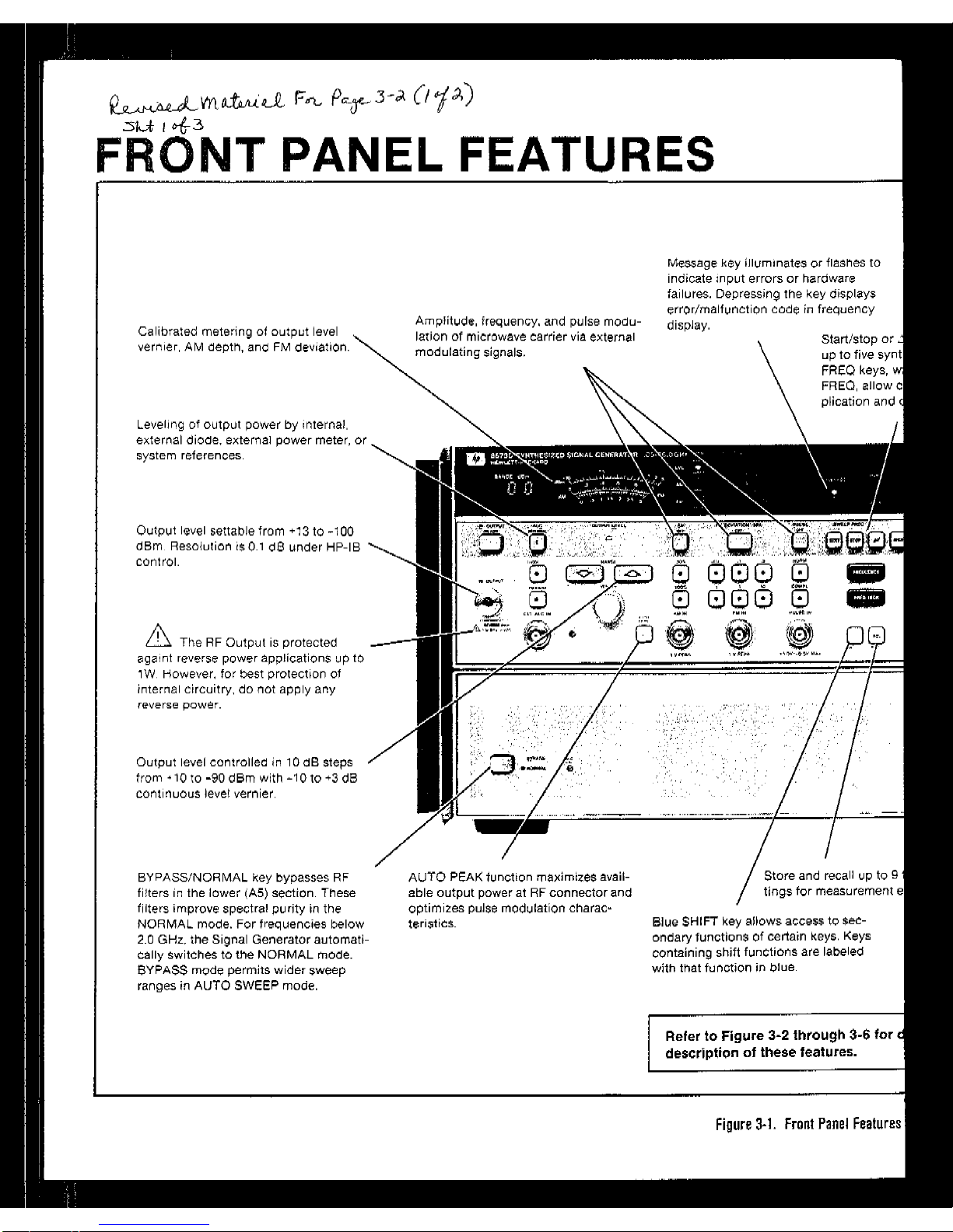
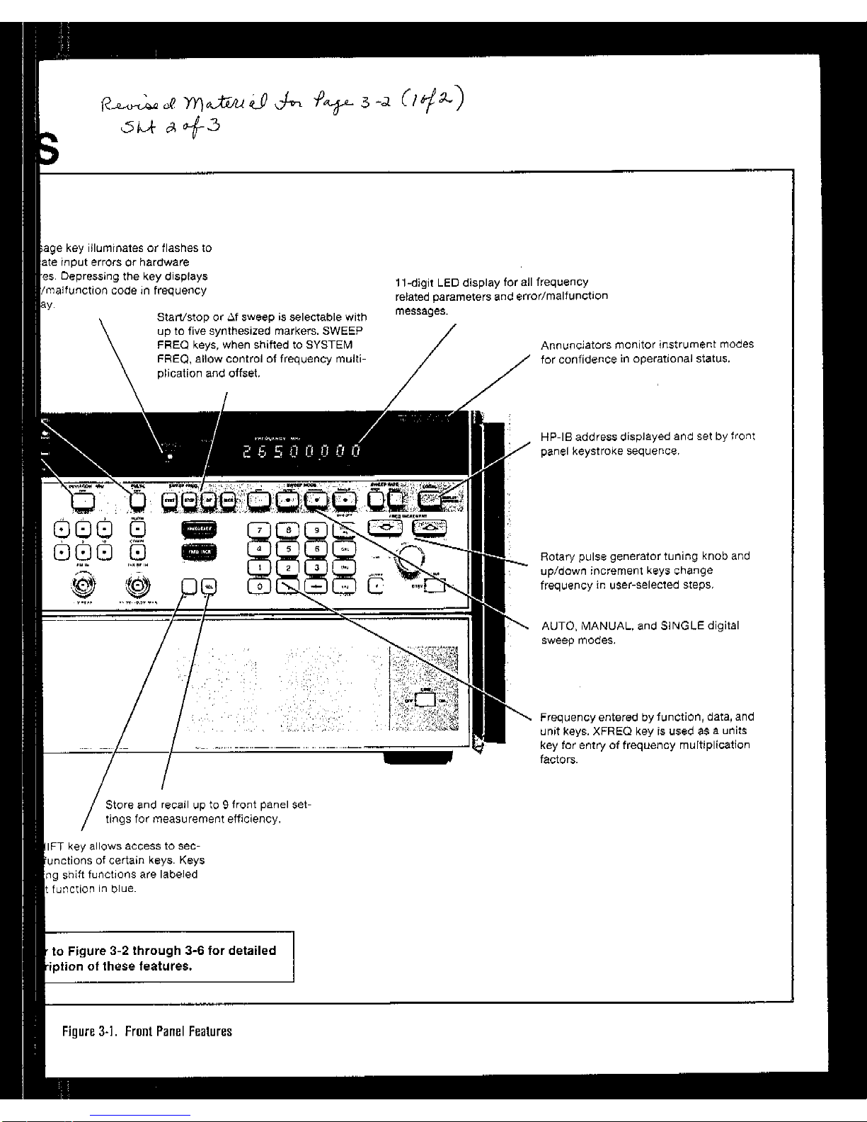
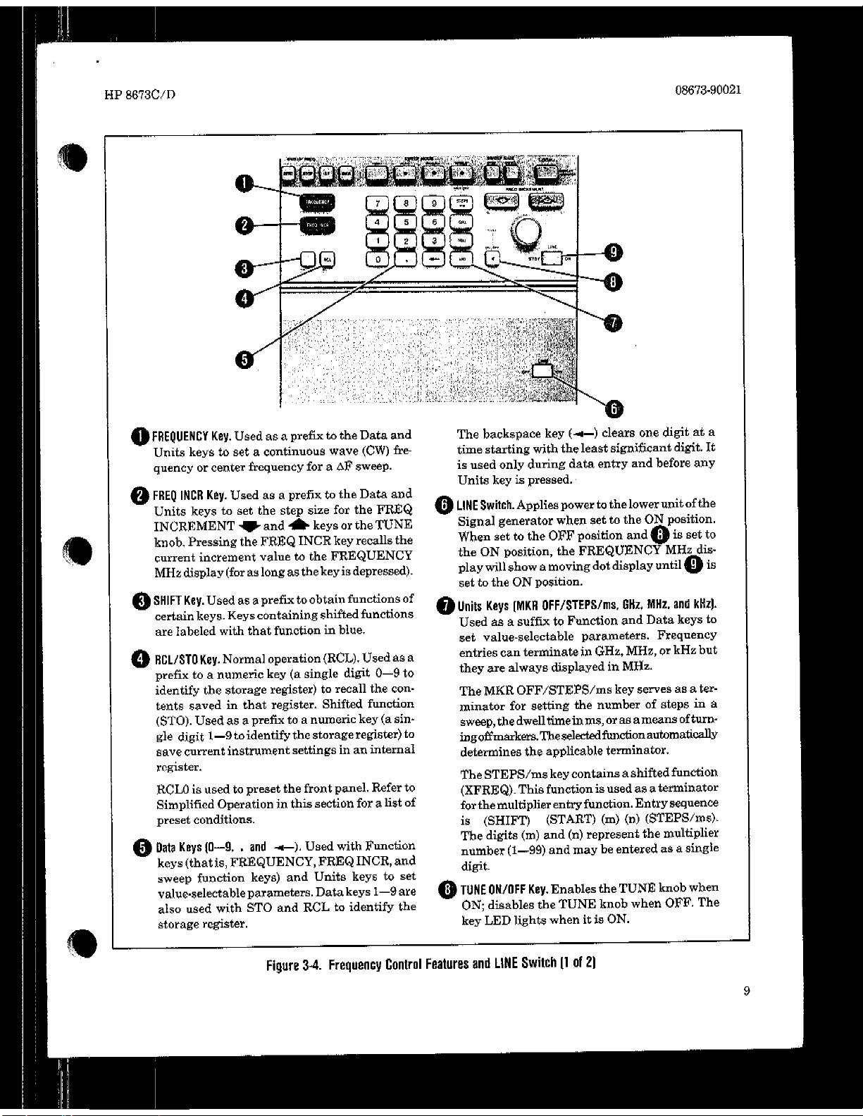
Front Panel Features .......................
.32
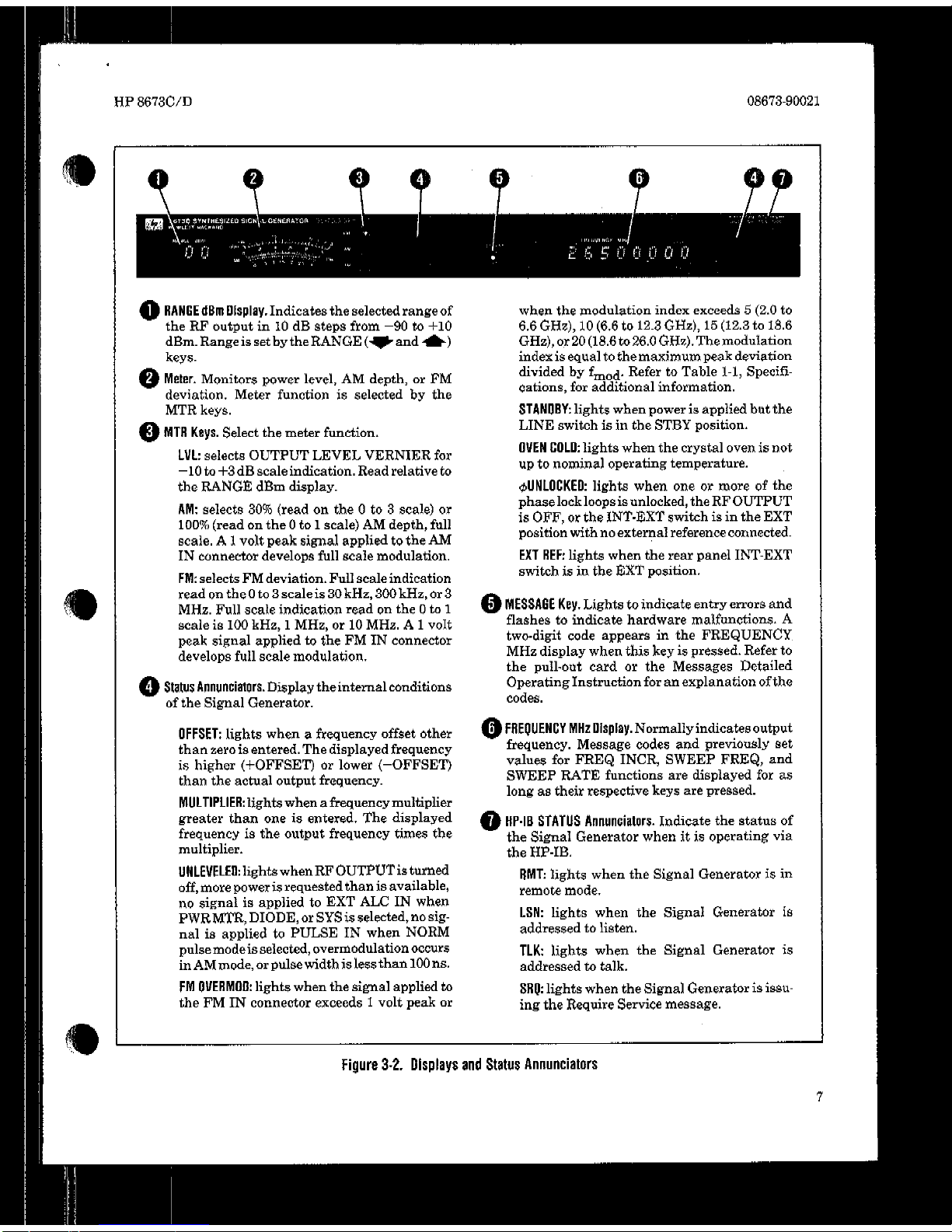
Displays and Statue Annunciators ..........
.58
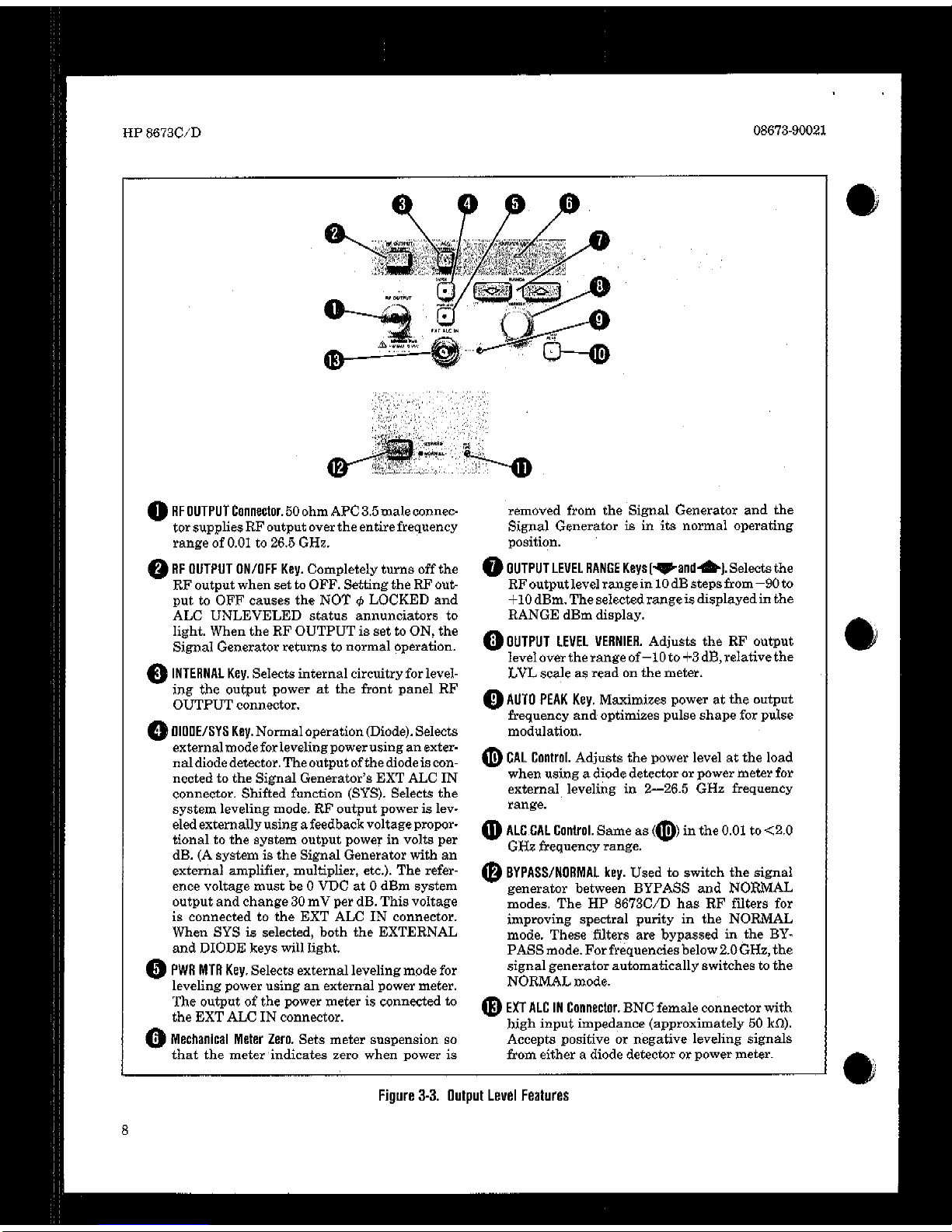
output Level Features .....................
.3-9
Frequency Control features and LINE
switch .................................
..510
Sweep Features and LOCAL Key ..........
,911
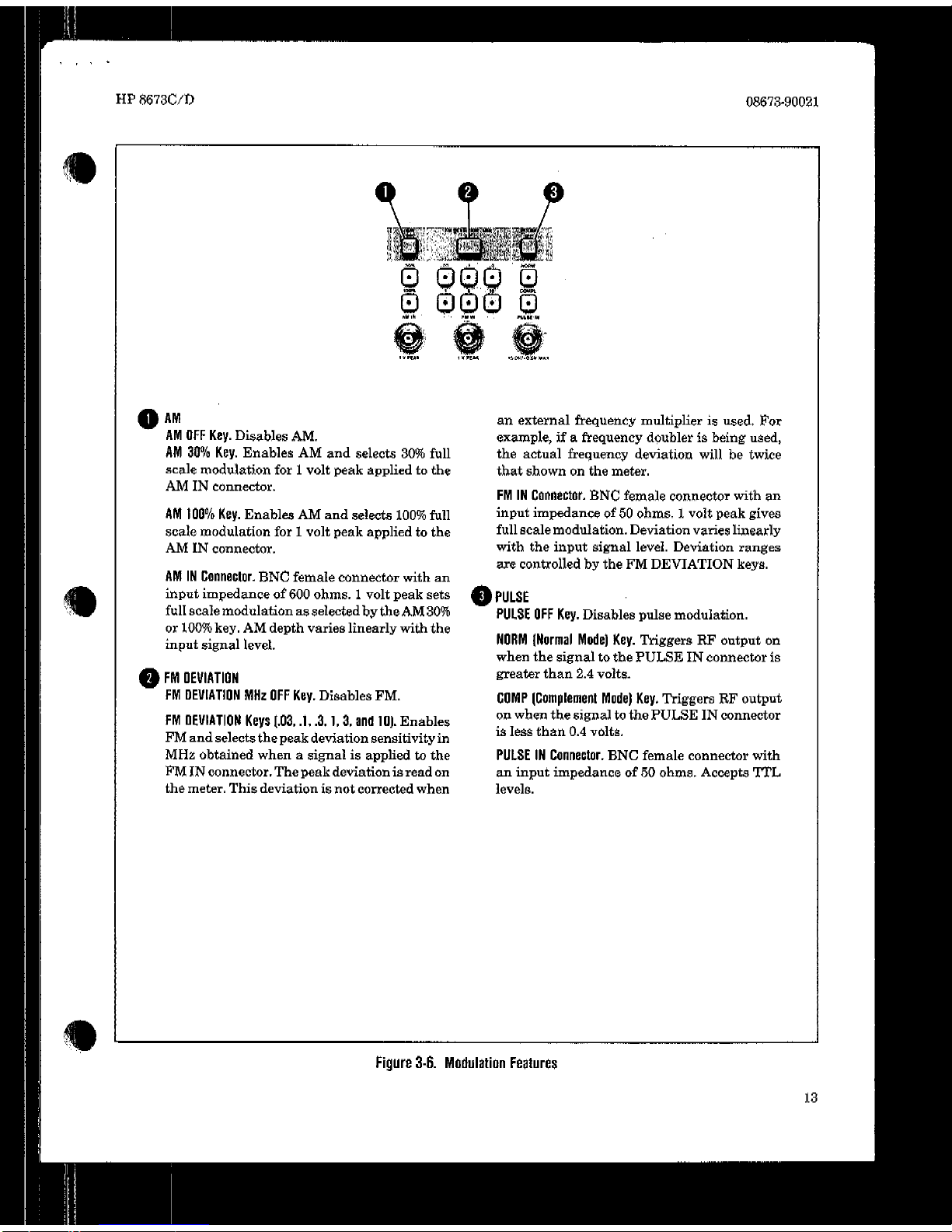
Modulation Features ......................
.S-12
57.
3-a.
s-9,
S-10.
Sll.
4-l.
4-2.
4-3.
4-4.
4-5.
4-6.
4.7.
4-8.
49.
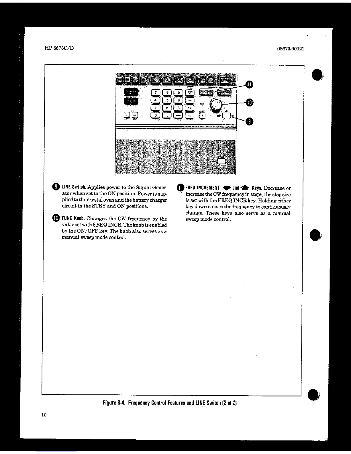
Rear Panel Features
.......................
.913
AM Fuixtional Check Setup
...............
,318
FM Functional Check Setup
................
S-19
Pulse Modulation Functional Check
setup ....................................
Z-20
Statue Byte Information.,
.................
,340
Frequency Range and Resolution Test
setup . . . , , . . .k3
High Level Accuracy and Flatness
Test Setup *. , . . . . , . .4-6
Low Level Accuracy Test Setup . *,. , . , .4-10
FM/AM Accuracy Test Setup. . . , . .4-13
AM Accuracy Test Setup . , , . .4-15
Low Frequency Pulse Test Setup.. , . , , . .4-17
Rise Time, Overshoot and Ringing
Measurement . . t t . . . .4-17
Pulse Level Accuracy Measurement.. . . . .4-18
High Frequency Pulse Test Setup . . . t 4-19
TABLES
Table Page Table Page
1.1.
1-2.
13.
1-4.
2-l.
3-L
3-2.
3-3.
3-4.
Specitications ...............................
l-4
Supplemental Characteristics ..............
l-11
Recommended Test Equipment
............ . l-14
Operation Verification Recommended
Test Equipment ...........................
l-18
Allowable HP-IB Address Codes
............. %3
Operating Characteristics ..................
.3-l
(Reserved for final manual),
................ .55
AWX Connector Functions ................
,530
Message Reference Table ...................
3-32
as.
56.
37.
34.
4-l.
4.2.
4.3.
4.4.
4.5.
4-6.
Talk Functions ............................
.3-37
Response to a Clear Message
...............
Z-38
HP-IB Program Codes
.....................
.3-41
Messages..
.............................. ..4-4 2
Maximum Leveled Output Power ...........
4-7
Level Flatness
.............................
4-9
High Level Accuracy ......................
4-9
Low Level Accuracy ......................
4-12
Risetime, Overshoot, and Peak Level
Accuracy ................................
4-20
Operation Verification Test Record ........ 4-21
iv
Page 23
HP 8673C/D Safety Considerations
SAFETY CONSIDERATIONS
GENERAL
This product and related documentation must be
reviewed for familiarization with safety markings
and instructions before operation.
This product is a Safety Class I instrument (pro-
vided with a protective earth terminal).
BEFORE APPLYING POWER
Verify that the product is set to match the available line voltage and the correct fuse is installed.
SAFETY EARTH GROUND
An uninterruptible safety earth ground must be
provided from the main power source to the product input wiring terminals, power cord, or sup
plied power cord set.
Any interruption of the protective (grounding)
conductor (inside or outside the instrument) or
disconnecting the protective earth terminal will
cause a potential shock hazard that could result in
personal injury. (Grounding one conductor of a
two conductor outlet is not sufficient protection.)
In addition, verify that a common ground exists
between the unit under test and this instrument
prior to energizing either unit.
Whenever it is likely that the protection has been
impaired, the instrument must be made inoperative
and be secured against any unintended operation.
If this instrument is to be energized via an auto-
transformer (for voltage reduction) make sure the
common terminal is connected to neutral (that is,
the grounded side of the mains supply).
Servicing instructions are for use by servicetrained personnel only. To avoid dangerous electric shock, do not perform any servicing unless
qualified to do so.
Adjustments described in the manual are performed with power supplied to the instrument
while protective covers are removed. Energy available at many points may, if contacted, result in
personal injury.
Capacitors inside the instrument may still be
charged even if the instrument has been discon-
nected from its source of supply.
For continued protection against fire hazard, re-
place the line fuse(s) only with 250V fuse(s) of the
same current rating and type (for example, normal
blow, time delay, etc.). Do not use repaired fuses or
short circuited fuseholders.
SAFETY SYMBOLS
Instruction manual symbol: the product
will be marked with this symbol when it is
necessary for the user to refer to the instruction manual (see Table of Contents for
page references).
Indicates hazardous voltages.
Indicates earth (ground) terminal.
The WARNING sign denotes a
hazard. It calls attention to a
procedure, practice, or the like,
which, if not correctly performed
or adhered to, could result in personal injury. Do not proceed beyond a WARNING sign until the
indicated conditions are fully
understood and met.
The CAUTION sign denotes a
hazard. It calls attention to an
operating procedure, practice, or
the like, which, if not correctly
performed or adhered to, could
result in damage to or destruction of part or all of the product.
Do not proceed beyond a CAUTION sign until the indicated
conditions are fully understood
and met.
Page 24
General Information
BP 8673C/D
MC-3.5 (F) to TYPE-N (F)
ADAPTER
HP 6673ClD
LINE POWER CABLE
ADAPTER
LINE POWER
CABLE
OPTION 908
RACK FLANGE KIT
OPTION 913
RACK FLANGE KIT
FOR INSTRUMENTS WITH HANDLES
Fkwe 1-l. HP 867X/D with AccessoriesSupplied. and Options 908 and 913 (HP 86730 shown).
Page 25
HP 8673WD
General Information
SECTION I
GENERAL INFORMATION
l-l. INTRODUCTlON
This manual contains information required to
install, operate, test, adjust and service the HP
8673C/D Synthesized Signal Generators. Figure
1-I shows an 8673D Signal Generator with all of
its externally supplied accessories.
The 8673C/D Operating and Service manual is
divided into two volumes and eight sections as
follows:
Volume 1 (Operating Information):
Section I, General Information
Section II, Installation
Section III, Operation
Section IV, Part 1
Operation Verification
Volume 2 (Service Information)
Section IV, Part 2
Performance Tests
Section
V,
Adjustments
Section VI, Replaceable Parts
Section VII, Manual Changes
Section VIII, Service
The 8673C/D 10 MHz Reference Oscillator A3A8,
is a field repairable component. A separate operat-
ing and service manual, HP Part No. 10811-90002,
is provided for this assembly and should be retained with the 8673C/D manual.
In addition, the following manuals are supplied
with the Signal Generator:
Volume 1 (two copies)
Volume 2 (one copy)
One copy of Volume 1 (Operating Information)
should remain with the instrument for use by the
operator. Additional copies of either volume can
be ordered separately through your nearest
Hewlett-Packard office. The part number is listed
on the title page of each volume.
Also listed on the title page of this volume, below
the manual part number, is a microfiche part
number. This number may be used to order 100 x
150 millimetre (4 x 6 inch) microfilm transparencies of the complete operating and service manual
(Volumes 1 and 2). Each microfiche contains up to
96 photo-duplicates of the manual pages, The
microfiche package also includes the latest Man-
ual Changes supplement, as well as all pertinent
Service Notes.
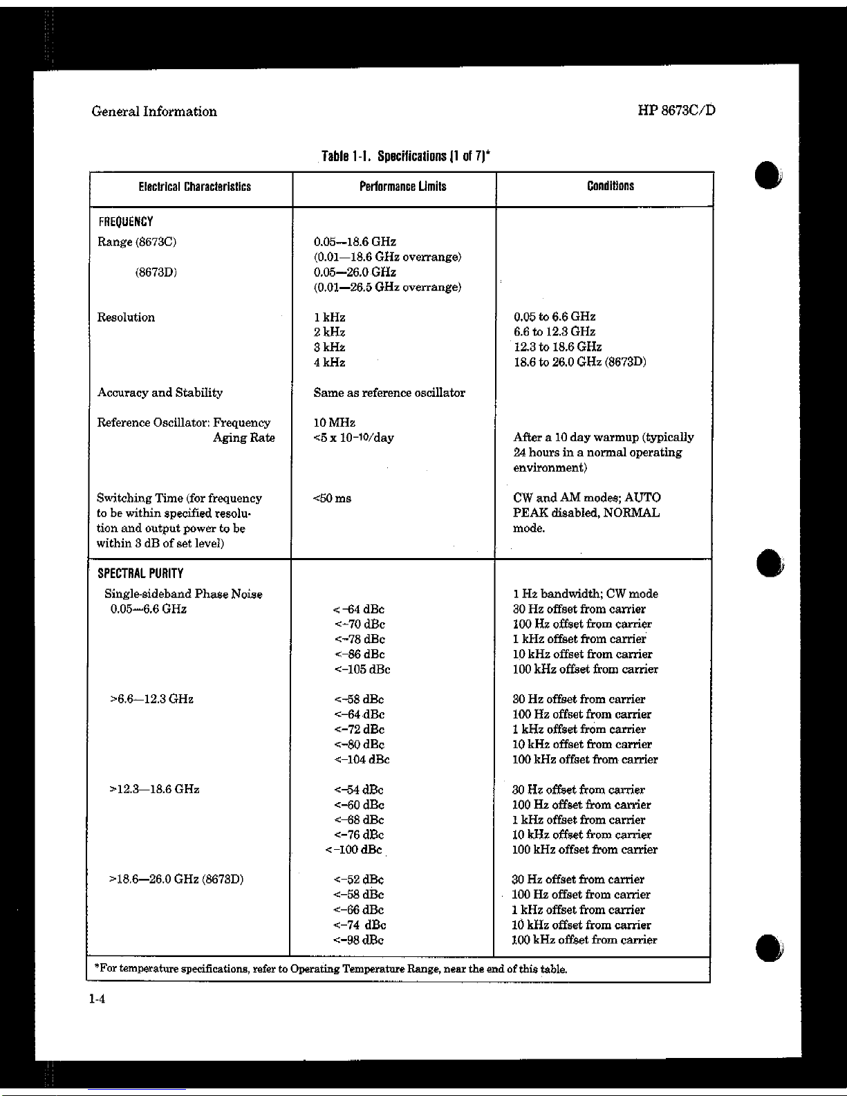
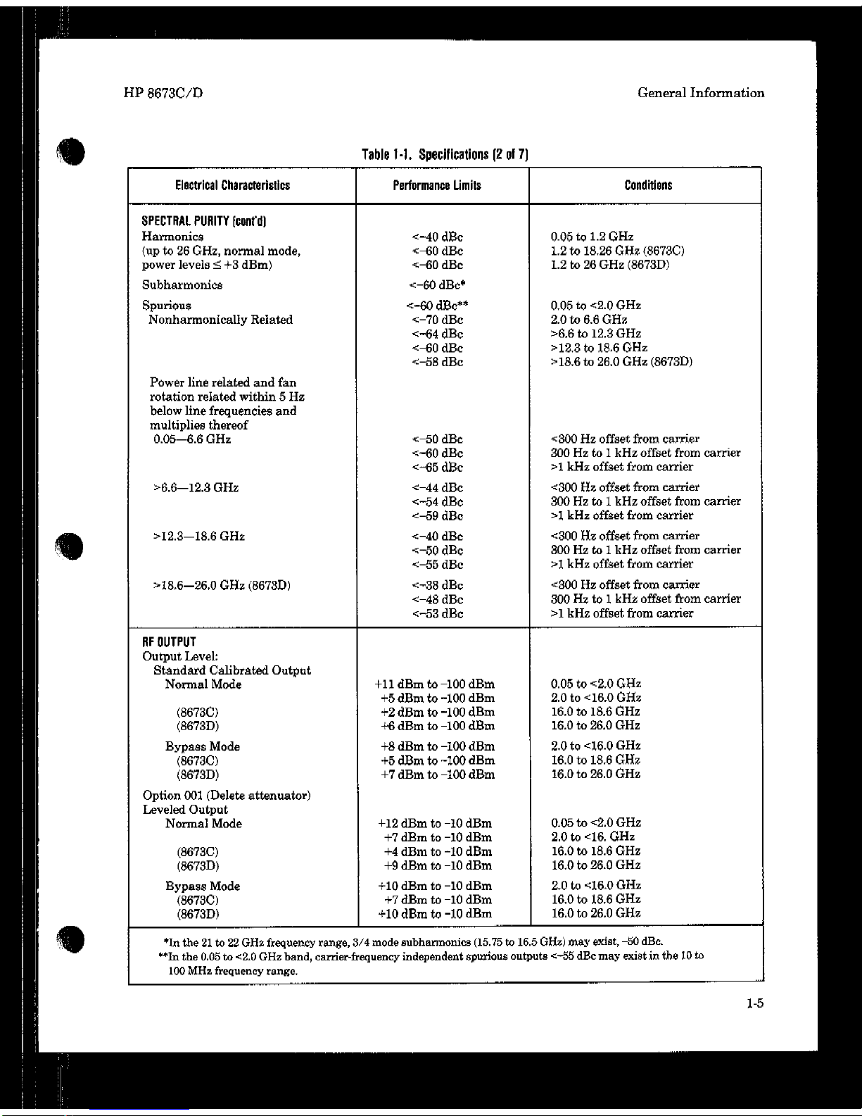
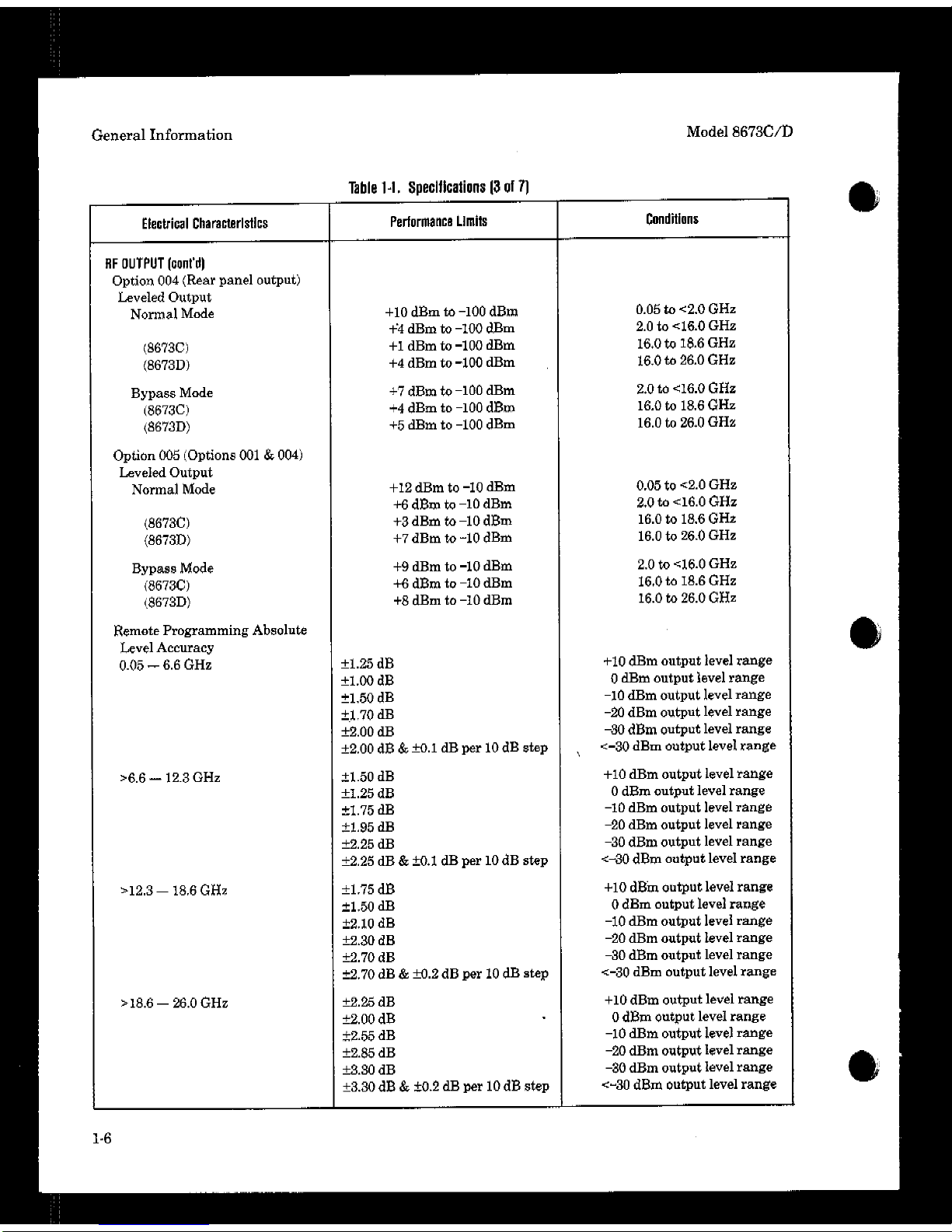
l-2. SPEClFlCATlONS
Instrument specifications are listed in Table l-l.
These specifications are the performance standards or limits against which the instrument may
be tested, Supplemental characteristics are listed
in Table 1-2. Supplemental charactsristics are not
warranted specifications, but are typical characteristics included as additional information for
the user.
1-3. SAFETY CONSIDERATIONS
This product is a Safety Class I instrument, that
is, one provided with a protective earth terminal.
The Signal Generator and all related documentation should be reviewed for familiarization with
safety markings and instructions before operation. Refer to the Safety Considerations page
found at the beginning of this manual for a summary of the safety information. Safety information for installation, operation, performance testing, adjustment, or service is found in appropriate
places throughout this manual.
1-4. INSTRUMENTS COVERED BY THIS
MANUAL
Attached to the rear panel of the instrument is a
serial number plate. The serial number is in the
form: OOOOAOOOOO. The first four digits and the
letter are the serial number prefix. The last five
digits are the suffix. The prefix is the same for
identical instruments; it changes only when a configuration change is made to the instrument. The
suffix, however is assigned sequentially and is
different for each instrument. The contents of this
manual apply directly to instruments having the
serial number prefix(es) listed under SERIAL
NUMBERS on the title page.
1-5. MANUAL CHANGES SUPPLEMENT
An instrument manufactured after the printing of
this manual may have a serial number prefix that
is not listed on the title page. This unlisted serial
number prehx indicates that the instrument is different from those documented in this manual. The
1-I
Page 26
Page 27
Page 28
Page 29
Page 30
Page 31

Page 32

Page 33

Page 34

Page 35

Page 36

Page 37

Page 38

Page 39

Page 40

Page 41

Page 42

Page 43

Page 44
Page 45

Page 46

Page 47
Page 48

Page 49

Page 50

Page 51

Page 52

Page 53

Page 54

Page 55

Page 56

Page 57

Page 58

Page 59

Page 60

Page 61

Page 62

Page 63

Page 64

Page 65

Page 66

Page 67

Page 68

Page 69

Page 70

Page 71

Page 72

Page 73

Page 74

Page 75

Page 76
Page 77

Page 78

Page 79

Page 80

Page 81

Page 82

Page 83

Page 84

Page 85

Page 86

Page 87

Page 88

Page 89

Page 90

Page 91

Page 92

Page 93

Page 94

Page 95

Page 96

Page 97

Page 98

Page 99

Page 100

 Loading...