

Errata
Title & Document Type: 8671B Synthesized CW Generator Operating Manual
Manual Part Number: 08671-90019
Revision Date: December 1985
HP References in this Manual
This manual may contain references to HP or Hewlett-Packard. Please note that Hewlett-Packard's former test and measurement, semiconductor products and chemical analysis businesses are now part of Agilent Technologies. We have made no changes to this manual copy. The HP XXXX referred to in this document is now the Agilent XXXX. For example, model number HP8648A is now model number Agilent 8648A.
About this Manual
We've added this manual to the Agilent website in an effort to help you support your product. This manual provides the best information we could find. It may be incomplete or contain dated information, and the scan quality may not be ideal. If we find a better copy in the future, we will add it to the Agilent website.
Support for Your Product
Agilent no longer sells or supports this product. You will find any other available product information on the Agilent Test & Measurement website:
www.tm.agilent.com
Search for the model number of this product, and the resulting product page will guide you to any available information. Our service centers may be able to perform calibration if no repair parts are needed, but no other support from Agilent is available.

HP 867
Contents
HP 8671B
CONTENTS
Page
Section I GENERAL INFORMATION
| t traduction 1- | 1 |
|---|---|
| Introduction 1- | 1 |
| Specifications | ī |
| Safety Considerations 1- | 1 |
| Instruments Covered by This Manual 1- | 1 |
| 111Strantons Supplement | 1 |
| Manual Changes Supplement | 9 |
| Description | م |
| Options 1- | 2 |
| Mechanical Options 1- | 2 |
| A suggering Supplied | 2 |
| Accessories Supplied | ว |
| Accessories Available 1- |
ပ
ဂ |
| Electrical Equipment Available 1- | З |
| Becommonded Test Equipment | 3 |
| Recommended 1000 Dearphone to the test |
Section II
| Introduction | 2-1 |
|---|---|
| Initial Inspection | 2-1 |
| Preparation For Use | 2-1 |
| Power Requirements | 2-1 |
| Line Voltage and Fuse Selection | 2-1 |
| ∧ Power Cables | 2-1 |
| HP-IB Address Selection | 2-2 |
| Interconnections | 2-3 |
| Mating Connectors | 2-3 |
| Operating Environment | 2-3 |
| Bench Operation | 2-4 |
| Rack Mounting | 2-4 |
| Storage and Shipment | 2-4 |
| Environment | 2-4 |
| Packaging | 2-4 |
Section III OPERATION
| Introduction | 3-1 |
|---|---|
| Panel Features | 3-1 |
| Operating Characteristics | 3-1 |
| Local Operation | 3-1 |
| Remote (HP-IB) Operation | 3-1 |
| Operator's Checks | 3-1 |
| Operator's Maintenance | 3-1 |
| Turn-On Instructions | 3-1 |
| Turn-On | 3-1 |
| Frequency Standard Selection | 3-1 |
| Simplified Operation | 3-3 |
| Frequency | 3-3 |
| Output Level | 3-3 |
| ALC | 3-3 |
| Page | |
|---|---|
| ALC Control | . 3-4 |
| Frequency Control | . 3-8 |
| Level Control | 3-12 |
| Peak-Norm Adjustment | 3-15 |
| RF ON/OFF Switch | 3-16 |
| Remote (HP-IB) Operation | 3-17 |
| HP-IB Compatibility | 3-17 |
| Remote Mode | 3-17 |
| Local Mode | 3-17 |
| Addressing | 3-17 |
| Data Messages | 3-17 |
| Receiving Data Messages | 3-19 |
| The Complete Data Message | 3-19 |
| The Abbreviated Data Message | 3-19 |
| Receiving the Clear Message | 3-19 |
| Receiving the Trigger Message | 3-20 |
| Receiving the Remote Message | 3-20 |
| Receiving the Local Message | 3-20 |
| Receiving the Local Lockout Message | 3-20 |
| Receiving the Clear Lockout/Set Local | |
| Message | 3-20 |
| Receiving the Pass Control Message | 3-20 |
| Sending the Require Service Message | 3-20 |
| Sending the Status Byte Message | 3-20 |
| Sending the Status Bit Message | 3-20 |
| Receiving the Abort Message | 3-20 |
| Operator's Checks | , 3-22 |
| Basic Functional Checks | . 3-22 |
| HP-IB Checks | . 3-26 |
Section IV PERFORMANCE TESTS
| Introduction 4-1 |
|---|
| Abbreviated Performance Test 4-1 |
| Calibration Cycle 4-1 |
| Performance Test Record 4-1 |
| Equipment Required 4-1 |
| Test Procedures 4-1 |
| Frequency Range and Resolution Test 4-2 |
| Frequency Switching Time Test 4-5 |
| Output Level, High Level Accuracy |
| and Flatness Test 4-11 |
| Low Level Accuracy Test 4-16 |
| Output Level Switching Time Test 4-20 |
| Harmonics, Subharmonics & Multiples Test 4-23 |
| Non-Harmonically Related Spurious |
| Signals Test 4-26 |
| Power Line Related Spurious Signals Test 4-28 |
| Single-Sideband Phase Noise Test 4-31 |
| Internal Time Base Aging Rate 4-36 |
L
Contents
ILLUSTRATIONS
| Figu | re Page |
|---|---|
| 1-1. |
HP Model 8671B Accessories Supplied, and
Options 907, 908, and 909 1-0 |
| 2-1. | Line Voltage and Fuse Selection |
| 2-2. | Power Cable and Mains Plug Part |
| Numbers 2-2 | |
| 2-3. | HP-IB Address Switches Shown as Set by |
| the Factory 2-3 | |
| 2-4. | Hewlett-Packard Interface Bus |
| Connection 2-5 | |
| ∆ 3-1. | Front Panel Features |
| 3-2. | Rear Panel Features |
| 3-3. | External Leveling with a Crystal Detector 3-4 |
| 3-4. | External Leveling with a Power Meter 3-5 |
| 3-5. |
Frequency Programming Codes and
Arguments |
| 3-6. |
Frequency Switching Time Showing
Worst Case 3-11 |
| 3-7. | Frequency Checks Test Setup 3-23 |
| Figu | re Page |
|---|---|
| 4-1. | Frequency Range and Resolution |
| Test Setup 4-2 | |
| 4-2. | Frequency Switching Time Test Setup 4-6 |
| 4-3. | Frequency Switching Time Measurement |
| Waveform 4-8 | |
| 4-4. | Amplitude Recover Measurement |
| Waveform 4-10 | |
| 4-5. | Output Level, High Level Accuracy |
| and Flatness Test Setup 4-12 | |
| 4-6. | Low Level Accuracy Test Setup 4-17 |
| 4-7. | Output Level Switching Time Test Setup 4-20 |
| 4-8 | Output Level Switching Time |
| Measurement Waveform 4-22 | |
| 4-9. | Harmonics, Subharmonics, and Multiples |
| Test Setup 4-23 | |
| 4-10. | Non-Harmonically Related Spurious |
| Test Setup 4-26 | |
| 4-11. | Power Line Related Spurious Signals |
| Test Setup 4-29 | |
| 4-12. | Single-Sideband Phase Noise Test Setup 4-32 |
| 4-13. | Internal Time Base Aging Rate |
| Test Setup |
TABLES
| Tabl | e Page |
|---|---|
| 1-1. | Specifications 1-4 |
| 1-2. | Supplemental Characteristics 1-7 |
| 1-3. | Recommended Test Equipment 1-8 |
| 2-1. | Allowable HP-IB Address Codes 2-3 |
| 3-1. | Operating Characteristics 3-1 |
| 3-2. | Index of Detailed Operating Instructions 3-1 |
| 3-3. | Message Reference Table 3-18 |
| Tab | le Page |
|---|---|
| 3-4. | Programming Quick Reference Guide 3-21 |
| 4-1. | Output Level, High Level Accuracy |
| and Flatness Test Record 4-14 | |
| 4-2. | Low Level Accuracy Test Record 4-19 |
| 4-3. | Harmonics, Subharmonics & Multiples |
| Test Record 4-25 | |
| 4-4. | Performance Test Record 4-38 |
SAFETY CONSIDERATIONS
GENERAL
This product and related documentation must be reviewed for familiarization with safety markings and instructions before operation.
This product is a Safety Class I instrument (provided with a protective earth terminal).
BEFORE APPLYING POWER
Verify that the product is set to match the available line voltage and the correct fuse is installed.
SAFETY EARTH GROUND
An uninterruptible safety earth ground must be provided from the main power source to the product input wiring terminals, power cord, or supplied power cord set.
WARNINGS
Any interruption of the protective (grounding) conductor (inside or outside the instrument) or disconnecting the protective earth terminal will cause a potential shock hazard that could result in personal injury. (Grounding one conductor of a two conductor outlet is not sufficient protection.) In addition, verify that a common ground exists between the unit under test and this instrument prior to energizing either unit.
Whenever it is likely that the protection has been impaired, the instrument must be made inoperative and be secured against any unintended operation.
If this instrument is to be energized via an autotransformer (for voltage reduction) make sure the common terminal is connected to neutral (that is, the grounded side of the mains supply).
Servicing instructions are for use by servicetrained personnel only. To avoid dangerous electric shock, do not perform any servicing unless qualified to do so.
Adjustments described in the manual are performed with power supplied to the instrument
while protective covers are removed. Energy available at many points may, if contacted, result in personal injury.
Capacitors inside the instrument may still be charged even if the instrument has been disconnected from its source of supply.
For continued protection against fire hazard, replace the line fuse(s) only with 250V fuse(s) of the same current rating and type (for example, normal blow, time delay, etc.). Do not use repaired fuses or short circuited fuseholders.
SAFETY SYMBOLS
Instruction manual symbol: the product will be marked with this symbol when it is necessary for the user to refer to the instruction manual (see Table of Contents for page references).

Indicates hazardous voltages.
Indicates earth (ground) terminal.
WARNING
The WARNING sign denotes a hazard. It calls attention to a procedure, practice, or the like, which, if not correctly performed or adhered to, could result in personal injury. Do not proceed beyond a WARNING sign until the indicated conditions are fully understood and met.
CAUTION
The CAUTION sign denotes a hazard. It calls attention to an operating procedure, practice, or the like, which, if not correctly performed or adhered to, could result in damage to or destruction of part or all of the product. Do not proceed beyond a CAU-TION sign until the indicated conditions are fully understood and met.

General Information
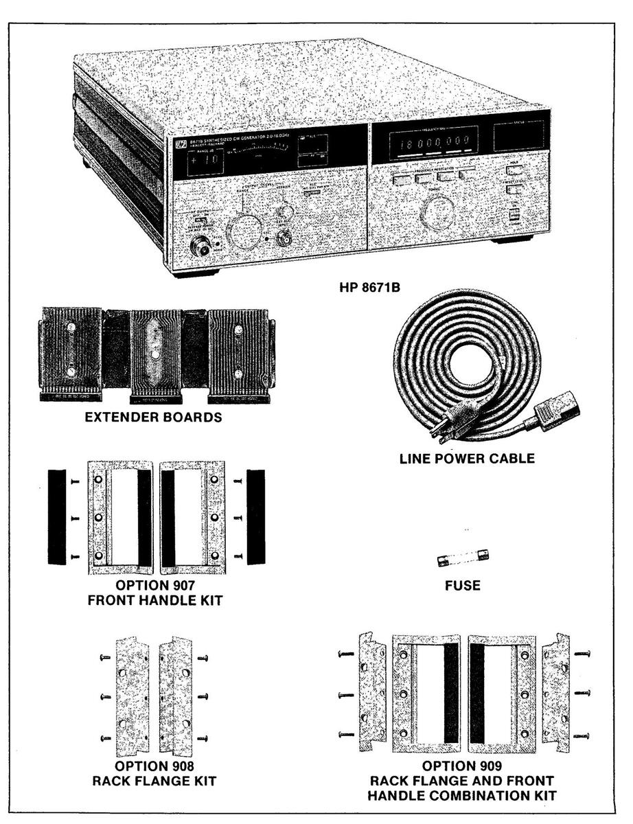
Figure 1-1. HP Model 8671B Accessories Supplied, and Options 907, 908, and 909
SECTION I GENERAL INFORMATION
1-1. INTRODUCTION
This manual contains information required to install, operate, test, adjust and service the Hewlett-Packard 8671B Synthesized CW Generator. Figure 1-1 shows the CW Generator with all of its externally supplied accessories.
The 8671B Operating and Service manual has eight sections. The subjects addressed are:
Section I, General Information Section II, Installation Section III, Operation Section IV, Performance Tests Section V, Adjustments Section VI, Replaceable Parts Section VII, Manual Changes Section VIII, Service
Two copies of the operating information are supplied with the CW Generator. One copy is in the form of an Operating Manual. The Operating Manual is a copy of the first four sections of the Operating and Service Manual. The Operating Manual should stay with the instrument for use by the operator. Additional copies of the Operating Manual can be ordered separately through your nearest Hewlett-Packard office. The part number is listed on the title page of this manual.
Also listed on the title page of this manual, below the manual part number, is a microfiche part number. This number may be used to order 100 x 150 millimetre (4 x 6 inch) microfilm transparencies of this manual. Each microfiche contains up to 96 photo-duplicates of the manual pages. The microfiche package also includes the latest Manual Changes supplement, as well as all pertinent Service Notes.
1-2. SPECIFICATIONS
Instrument specifications are listed in Table 1-1. These specifications are the performance standards or limits against which the instrument may be tested. Supplemental characteristics are listed in Table 1-2. Supplemental characteristics are not warranted specifications, but are typical characteristics included as additional information for the user.
1-3. SAFETY CONSIDERATIONS
This product is a Safety Class I instrument, that is, one provided with a protective earth terminal. The CW Generator and all related documentation should be reviewed for familiarization with safety markings and instructions before operation. Refer to the Safety Considerations page found at the beginning of this manual for a summary of the safety information. Safety information for installation, operation, performance testing, adjustment, or service is found in appropriate places throughout this manual.
1-4. INSTRUMENTS COVERED BY THIS MANUAL
Attached to the rear panel of the instrument is a serial number plate. The serial number is in the form: 0000A00000. The first four digits and the letter are the serial number prefix. The last five digits are the suffix. The prefix is the same for identical instruments; it changes only when a configuration change is made to the instrument. The suffix however, is assigned sequentially and is different for each instrument. The contents of this manual apply directly to instruments having the serial number prefix(es) listed under SERIAL NUMBERS on the title page.
1-5. MANUAL CHANGES SUPPLEMENT
An instrument manufactured after the printing of this manual may have a serial number prefix that is not listed on the title page. This unlisted serial number prefix indicates that the instrument is different from those documented in this manual. The manual for this newer instrument is accompanied by a Manual Changes supplement. The supplement contains "change information" that explains how to adapt this manual to the newer instrument.
In addition to change information, the supplement may contain information for correcting errors in the manual. To keep the manual as current and as accurate as possible, Hewlett-Packard recommends that you periodically request the latest Manual Changes supplement. The supplement is identified with the manual print date and part number, both
MANUAL CHANGES SUPPLEMENT (cont'd)
of which appear on the manual title page. Complimentary copies of the supplement are available from Hewlett-Packard.
For information concerning a serial number prefix that is not listed on the title page or in the Manual Changes supplement, contact your nearest Hewlett-Packard office.
1-6. DESCRIPTION
The HP 8671B Synthesized CW Generator has a frequency range of 2.0 to 18.0 GHz. The output is leveled and calibrated from +8 dBm to -120 dBm. Frequency, output level, and ALC modes can be remotely programmed via HP-IB.
The frequency can be tuned with one of four frequency resolutions. Tuning resolutions of 100 MHz, 1 MHz, 10 kHz or 1 kHz are selected by front panel pushbuttons. The 1 kHz tuning resolution will give tuning resolutions of 1 kHz for frequencies from 2.0 to 6.2 GHz, 2 kHz for frequencies from 6.2 to 12.4 GHz, and 3 kHz for frequencies from 12.4 to 18.599997 GHz.
Long-term frequency stability is dependent on the time base, either an internal or external reference oscillator. The internal crystal reference oscillator operates at 10 MHz while an external oscillator may operate at 5 or 10 MHz.
The output of the CW Generator is exceptionally flat due to the action of the internal automatic leveling control (ALC) loop. External leveling control using a diode detector or a power meter to sense output power can be used to level the output at a remote load.
The output level is set using the OUTPUT LEVEL RANGE switch and the OUTPUT LEVEL VERN-IER. The OUTPUT LEVEL RANGE switch changes the output level in 10 dB increments (+10 to -110 dB). The OUTPUT LEVEL VERNIER is then used to adjust the output level over a continuous 13 dB range (-10 to +3 dBm). The output level is read by adding the vernier setting to the range setting.
The CW Generator is compatible with HP-IB to the extent indicated by the following codes: SH1, AH1, T6, TE0, L4, LE0, SR1, RL2, PP2, DC1, DT0, and C0. An explanation of the compatibility code can be found in IEEE Standard 488 (1978),
"IEEE Standard Digital Interface for Programmable Instrumentation" or the identical ANSI Standard MC1.1. For more detailed information relating to programmable control of the CW Generator, refer to Remote Operation, Hewlett-Packard Interface Bus in Section III of this manual
1-7. OPTIONS
1-8. Mechanical Options
The following options may have been ordered and received with the CW Generator. If they were not ordered with the original shipment and are now desired, they can be ordered from the nearest Hewlett-Packard office using the part numbers included in each of the following paragraphs.
Option 907 (Front Handle Kit). Ease of handling is increased with the front panel handles. The Front Handle Kit part number is 5061-9689.
Option 908 (Rack Flange Kit). The CW Generator can be solidly mounted to the instrument rack using the flange kit. The Rack Flange Kit part number is 5061-9677.
Option 909 (Rack Flange and Front Handle Combination Kit). This is a unique part which combines both functions. It is not simply a front handle kit and a rack flange kit packaged together. The Rack Flange and Front Panel Combination Kit part number is 5061-9683.
1-9. ACCESSORIES SUPPLIED
The accessories supplied with the CW Generator are shown in Figure 1-1.
a. The line power cable is supplied in several configurations, depending on the destination of the original shipment. Refer to Power Cables in Section II of this manual.
b. An additional fuse is shipped only with instruments that are factory configured for 100/120 Vac operation. This fuse has a 1.5A rating and is for reconfiguring the instrument for 220/240 Vac operation.
c. Four extender boards are supplied for performance testing, adjusting, and troubleshooting the instrument.
1. One 30-pin (15 x 2) extender board, HP part number 08672-60117.
ACCESSORIES SUPPLIED (cont'd)
- 2. Two 36-pin (18 x 2) extender boards, HP part number 08672-60020.
- 3. One 3-section, 30-pins (15 x 2) per section, extender board, HP part number 08672-60016 (for use in the A2 Assembly).
1-10. ACCESSORIES AVAILABLE
Chassis Slide Mount Kit. This kit is not available as a factory installed option. However, it is extremely useful when the CW Generator is rack mounted. Access to internal circuits and components or the rear panel is possible without removing the CW Generator from the rack. Order HP part number 1494-0059. If the instrument rack mounting slides are to be mounted in a standard EIA rack, then an adapter (HP Part No. 1494-0061) is needed. The slides without the adapter can be directly mounted in the HP system enclosures.
1-11. ELECTRICAL EQUIPMENT AVAILABLE
The CW Generator has an HP-IB interface and can be used with any HP-IB compatible computing controller or computer for automatic systems applications.
The HP-IB Controller is needed for Flatness and ALC adjustment procedures and for performance testing. Controllers that are supported by this manual include the HP 9826A, 9836A, and HP 85B/82937A.
The HP 11720A Support Kit is available for maintaining and servicing the CW Generator. It includes a special test extender board, cables and adapters.
1-12. RECOMMENDED TEST EQUIPMENT
Table 1-3 lists the test equipment recommended for testing, adjusting and servicing the CW Generator. Essential requirements for each piece of test equipment are described in the Critical Specifications column. Other equipment can be substituted if it meets or exceeds these critical specifications.
1
Table 1-1. Specifications (1 of 3)
Note: Specifications apply after 1-hour warm-up, over the temperature range 0 to 55°C (except specifications for RF output level which apply over the range 15 to 35° C). Specifications for output flatness and absolute level accuracy apply only when internal leveling is used.
| Electrical Characteristics | Performance Limits | Conditions |
|---|---|---|
|
FREQUENCY
Range |
2.0—18.0 GHz
(Overrange to 18.599997 GHz) |
' |
| Resolution |
1 kHz
2 kHz 3 kHz |
2.0 to 6.2 GHz
6.2 to 12.4 GHz 12.4 to 18.0 GHz |
| Accuracy and Stability |
Same as reference
oscillator |
|
|
Switching Time
Frequency (to be within the specified resolution -1 kHz in 2.0 to 6.2 GHz range, etc.) |
<15 ms | |
|
Amplitude (after switching
frequency) to be within ±3 dB of final level |
<15 ms | When switching within the same range |
|
Reference Oscillator
Frequency |
10 MHz | |
| Aging Rate | <5 x 10 -10 /day |
After a 10 day warmup (typically
24 hours in a normal operating environment) |
| SPECTRAL PURITY | · | |
|
Single-sideband Phase Noise
2.0—6.2 GHz |
<58 dBc
<-70 dBc <-78 dBc <-86 dBc <-110 dBc |
1 Hz bandwidth
10 Hz offset from carrier 100 Hz offset from carrier 1 kHz offset from carrier 10 kHz offset from carrier 100 kHz offset from carrier |
| 6.2—12.4 GHz |
<-52 dBc
<-64 dBc <-72 dBc <-80 dBc <-104 dBc |
10 Hz offset from carrier
100 Hz offset from carrier 1 kHz offset from carrier 10 kHz offset from carrier 100 kHz offset from carrier |
| 12.4—18.0 GHz |
<-48 dBc
<-60 dBc <-68 dBc <-76 dBc <-100 dBc |
10 Hz offset from carrier
100 Hz offset from carrier 1 kHz offset from carrier 10 kHz offset from carrier 100 kHz offset from carrier |
| Harmonics | <−25 dBc | At +8 dBm |
HP 8671B
General Information
Table 1-1. Specifications (2 of 3)
| Electrical Characteristics | Performance Limits | Conditions |
|---|---|---|
| SPECTRAL PURITY (cont'd) | ||
| Subharmonics and multiples thereof | <-25 dBc | At +8 dBm |
| Spurious Signals, non-harmon- | <-70 dBc | 2.0—6.2 GHz |
| ically related, except power line | <-64 dBc | 6.2—12.4 GHz |
| and fan rotation related | <-60 dBc | 12.4—18.0 GHz |
|
Power line related and fan
rotation related within 5 Hz below line frequencies and |
||
| multiples thereof | <-50 dBc | <300 Hz offset from carrier |
| 2.0—6.2 GHZ | <-60 dBc | 300 Hz to 1 kHz offset from carrier |
| · | <-65 dBc | >1 kHz offset from carrier |
| 6 2_12 4 CHz | <-44 dBc | <300 Hz offset from carrier |
| 0.2-12.1 0112 | <-54 dBc | 300 Hz to 1 kHz offset from carrier |
| <-59 dBc | >1 kHz offset from carrier | |
| 12.4—18.0 GHz | <-40 dBc | <300 Hz offset from carrier |
| <-50 dBc | 300 Hz to 1 kHz offset from carrier | |
| <-55 dBc | >1 kHz offset from carrier | |
|
RF OUTPUT
Output Power |
+8 dBm to120 dBm | +15 to +35°C |
| Remote Programming Absolute | ||
| Level Accuracy | +10 dB output level range | |
| 2.0—6.2 GHz | 0 dB output level range | |
| ±1.00 dB | -10 dB output level range | |
| +1 70 dB | -20 dB output level range | |
| ±1.90 dB | -30 dB output level range | |
| ±1.90 dB & ±0.3 dB per 10 dB step | <-30 dB output level range | |
| 6 2—12 4 GHz | ±1.25 dB | +10 dB output level range |
| ±1.25 dB | 0 dB output level range | |
| ±1.75 dB | -10 dB output level range | |
| ±1.95 dB | -20 dB output level range | |
| ±2.15 dB | -30 dB output level range | |
| Con an oraling to to the Bo | ||
| 12.4—18.0 GHz | ±1.50 dB | +10 dB output level range |
| ±1.50 dB | 0 dB output level range | |
| ±2.10 dB | -10 dB output level range | |
| ±2.30 dB | -30 dB output level range | |
| +2.40 dB & ±0.4 dB per 10 dB step | <-30 dB output level range | |
1-5
1
1
| Electrical Characteristics | Performance Limits | Conditions |
|---|---|---|
|
RF OUTPUT (cont')
Manual Absolute Level Accuracy |
Add ±0.75 dB to remote
programming absolute level accuracy |
Absolute level accuracy specifica-
tions include allowances for detec- tor linearity, temperature, flatness, attenuator accuracy, and |
|
Remote Programming Output
Level Resolution |
1 dB | measurement uncertainty. |
| Flatness (total variation) | 0 dBm Range, +15°C to +35°C | |
|
1.50 dB
2.00 dB 2.50 dB |
2.0 to 6.2 GHz
2.0 to 12.4 GHz 2.0 to 18.0 GHz |
|
|
Output Leveling Switching
Time (to be within ±1 dB of final level) |
<20 ms | |
|
REMOTE OPERATION
Frequency |
Programmable over the full range v
mode. |
with the same resolution as manual |
|
Output Level
RF Output ALC |
Programmable in 1 dB steps, +8 to
Programmable to either ON or OFF Programmable for internal, crystal |
–120 dBm, plus 5 dB of overrange
F. diode, or power meter leveling. |
| Interface Function Codes | SH1, AH1, T6, TE0, L4, LE0, SR1, I | RL2, PP2, DC1, DT0, and C0. |
|
GENERAL
Operating Temperature |
0 to +55°C (see note at the beginning | ng of this table). |
| Power | 100, 120, 220, or 240V, +5%, -10%, 4 | 48—66 Hz, 300 VA maximum. |
| E.M.I. |
Conducted and radiated interference
MIL-I-6181D. |
ce is within the requirements of |
| Net Weight | 27.2 kg (60 lbs) | |
|
Dimensions: Height
Width Depth |
146 mm (5.7 in.)
425 mm (16.8 in.) 620 mm (24.4 in.) For ordering cabinet accessories, m System II |
odule sizes are 5-1/4H, 1 MW, 23D, |
| Accessories | Power Cord, Operating and Service extender boards. | Manual, and four |
Table 1-1. Specifications (3 of 3)
HP 8671B
Table 1-2. Supplemental Characteristics
Supplemental characteristics are intended to provide information useful in applying the instrument by giving typical, but non-warranted, performance parameters.
FREQUENCY
Internal Reference: The internal reference oscillator accuracy is a function of time base calibration ± aging rate, ± temperature effects, and ± line voltage effects. Typical temperature and line voltage effects are <1 x 10⁻⁷/°C and <5 x 10⁻¹⁰/+5% to -10% line voltage change. Reference oscillator is kept at operating temperature in STANDBY mode with the instrument connected to mains power. The aging rate is <1.5 x 10⁻⁹/day after a 24 hour warmup.
External Reference Input: 5 or 10 MHz at a level of 0.1 to 1 Vrms into 50Ω. Stability and spectral purity of the microwave output will be partially determined by characteristics of the external reference frequency.
Reference Outputs: 10 MHz at a level of 0.2 Vrms into 50Ω. 100 MHz at a level of 0.2 Vrms into 50Ω.
SPECTRAL PURITY
Residual FM : 80 Hz rms in a 50 Hz—15 kHz Post-detection bandwidth from 2—6.2 GHz. Residual FM doubles in the 6.2—12.4 GHz range and triples in the 12.4—18.0 GHz range.
RF OUTPUT
For power settings >+3 dBm, changes in frequency from <10 GHz to >16 GHz may require a settling period for the power to stabilize at the set level. Spurious output oscillations may occur for settings above +8 dBm.
External leveling device characteristics will determine output flatness, absolute level accuracy, and switching time in external leveling modes.
Maximum Reverse Power: 1W RF input; 1 MHz—20 GHz, 0 Vdc.
Impedance: 50Ω.
Source SWR: .
General Information
1
| ahla 1.9 | Recommended | Test Fauinme | nt (1 of 3) |
|---|---|---|---|
| 4006 1-0. | ncoummenucu | I COL LUUIDING |
| lnstrument | Critical Specifications |
Recommended
Model |
Use* |
|---|---|---|---|
| AC Voltmeter |
Range: 1 mV to 10V
Accuracy: ±1.5% of full scale ±1.5% of reading Frequency Response: 3 kHz to 3 MHz |
HP 400E | А |
|
Attenuator,
Fixed 3 dB |
Range: dc to 1 GHz
Accuracy: ±0.5 dB SWR: < 1.3 |
HP 8491A
Option 003 |
А |
|
Attenuator,
Fixed 20 dB |
Range: dc to 18 GHz
Accuracy: ±1.0 dB SWR: <1.6 |
HP 8491B
Option 020 |
C, P |
|
Cable, Special
Interconnect |
See YTO Loop Phase Detector Adjustments in
Section V |
Locally Fabricated | А |
| Controller, HP-IB |
HP-IB compatibility as defined by IEEE
Standard 488-1978 and the identical ANSI Standard MC1.1: SH1, AH1, T2, TE0, L2, LE0, SR0, RL0, PP0, DC0, DT0, and C1, 2, 3, 4, 5. |
HP 85B/82937A
or 9826A Option 011 or 9836A with BASIC 2.0 Operating System |
C, A,
T, P |
| Crystal Detector |
Frequency Range: 2 to 18 GHz
Frequency Response: ±1.5 dB |
HP 8470B
Option 012 |
P, A |
| Current Probe | Frequency Range: 2 to 35 MHz | HP 1110B | А |
|
Digital Voltmeter
(DVM) |
Range: -60V to +40V dc
Resolution: 100 µV on 1V dc range |
HP 3456A
or HP 3455A |
А, Т |
|
Foam Pads
(2 required) |
43 × 58 cm (17 × 23 in.), 5 cm (2 in.) thick | Р | |
| Frequency Counter |
Range: 2 to 18 GHz
Resolution: 1 kHz 10 MHz Frequency Standard Output: ≥0.1 Vrms |
HP 5343A | P, A, T |
| Frequency Standard | Long Term Stability: Better than 10 -10 /day | HP 5065A | P, A |
| High Impedance Probe |
Frequency: 400 MHz
Output Impedance: 50Ω (compatible with Spectrum Analyzer). |
HP 1121A | Т |
| Local Oscillator |
Range: 2 to 18 GHz
Level: +7 dBm Single Sideband Phase Noise and Spurious Signals: Same as HP 8340A |
HP 8340A | P, A |
| Logic State Analyzer | 8 Bit Display, Triggerable | HP 1630A | Т |
1-8
HP 8671B
| Table 1-3. | Recommended | Test Equipment | t (2 of 3 ) |
|---|
| Instrument | Critical Specifications |
Recommended
Model |
Use* |
|---|---|---|---|
| Logic Pulser | TTL compatible | HP 546A | Т |
| Mixer |
Response: 2 to 18 GHz
VSWR, LO: ≤ 2.5:1 VSWR, RF: ≤ 4.0:1 |
RHG DMS1–18 1 | P, A |
| Oscilloscope |
Bandwidth: 50 MHz
Vertical Sensitivity: 50 mV/div Vertical Input: 50Ω ac or dc coupled External Trigger Capability |
HP 1980B | P, A, T |
| Power Meter |
Frequency: 2 to 18 GHz
Range: +17 to -25 dBm |
HP 436A | Р, А, Т |
| Power Sensor |
r Sensor
Frequency: 2 to 18 GHz Input Impedance: 50Ω SWR: < 1.28 Range: +17 to -25 dBm Must be compatible with power meter |
Р, А, Т | |
|
Power Source,
Variable Frequency AC |
Range: 110 to 120 Vac
Frequency: 52 to 58 Hz Accuracy ± 2 Hz |
California Instruments
501TC/800T 2 |
Р |
| Power Supply | 0 to 40 Vdc | HP 6200B | A, T |
| Amplifier, Frequency: 100 kHz 20 dB Gain: 20 ± 5 dB' Output Power: > -10 dBm Noise Figure: < 5 dBm | Impedance: 50ΩHP 8447A | Р | |
|
Amplifier,
40 dB |
plifier, Frequency: 100 kHz H
Gain: 45 ± 5 dB Output Power: > -10 dBm Impedance: 50Ω |
Р | |
| Probe, 10:1 | Must be compatible with the oscilloscope. | HP 10017A | A |
| Signal Generator | Output Level: -5 to -20 dBm at 240 MHz | HP 8640B or HP 8340A | A |
|
Spectrum Analyzer
(with Tracking Generator) |
Frequency Range: 20 Hz to 300 kHz
Frequency Span/Division: 20 Hz minimum Noise Sidebands: > 90 dB below CW signal, 3 kHz offset, 100 Hz IF bandwidth Input Level Range: -10 to -60 dBm Log Reference Control: 70 dB dynamic range in 10 dB steps Accuracy: ± 0.2 dB |
HP 8556A/8552B/141T | А |
| Instrument | Critical Specifications |
Recommended
Model |
Use* |
|---|---|---|---|
| Spectrum Analyzer |
Frequency Range: 5 Hz to 50 kHz
Resolution Bandwidth: 1 Hz minimum Frequency Span/Division: 5 Hz to 500 Hz Amplitude Range: 0 to -70 dB |
HP 3580A | P, T |
| Spectrum Analyzer |
Frequency Range: 100 kHz to 22 GHz
Frequency Span/Division: 2 kHz minimum Amplitude Range: +10 to -90 dBm Noise Sideband: > 75 dB down 30 kHz from signal at 1 kHz resolution bandwidth Resolution Bandwidth: 30 Hz to 300 kHz |
HP 8566B | P, A |
| Sweep Oscillator |
Center Frequency: 150 to 200 MHz
Center Frequency Resolution: 0.1 MHz Sweep Range: 10 and 200 MHz |
HP 86222B/8620C
or HP 8340A |
A |
| Termination | 50Ω BNC | HP 11593A | Α |
| Termination | 600Ω BNC Feedthrough | HP 11095A | P, A |
| Test Coupler Adapter | See YTM Adjustments in Section V | Locally fabricated | A |
| Test Oscillator |
Level: 0 to 3V into 50Ω or 300Ω
Range: 60 Hz to 10 kHz |
HP 3335A | A, T |
| [ahie | 1.3 | Recommended | Toet | Fauinment | 13 of | 2) |
|---|---|---|---|---|---|---|
| םועם ו | 1-0. | ກຮວບແມ່ນເຮັບບໍ່ເ | 1621 | ะบบเมณะณ | 15 10 | പ |
* C = Operator's Check, P = Performance Tests, A = Adjustments, T = Troubleshooting
1 RHG Electronics Laboratory, Inc., 161 East Industry Court, Deer Park, NY 11729, Tel. (516) 242-1100, TWX 510-227-6083.
2 California Instruments, 5150 Convoy Street, San Diego, CA 92111, Tel. (714) 279-8620.
HP 8671B
SECTION II
2-1 INTRODUCTION
This section provides the information needed to install the CW Generator. Included is information pertinent to initial inspection, power requirements, line voltage selection, power cables, interconnection, environment, instrument mounting, storage and shipment.
2-2. INITIAL INSPECTION
WARNING
To avoid hazardous electrical shock, do not perform electrical tests when there are signs of shipping damage to any portion of the outer enclosure (covers, panels, meters).
Inspect the shinping container for damage. If the shipping container or cushioning material is damaged, it should be kept until the contents of the shinment have been checked for completeness and the instrument has been checked mechanically and electrically. The contents of the shinment should be as shown in Figure 1-1 Procedures for checking electrical performance are given in Section IV. If the contents are incomplete, if there is mechanical damage or defect. or if the instrument does not pass the electrical performance test. notify the nearest Hewlett-Packard office. If the shipping container is damaged or the cushioning material shows signs of stress. notify the carrier as well as the Hewlett-Packard office. Keep the shipping materials for the carrier's inspection.
2-3. PREPARATION FOR USE
2-4. Power Requirements
The CW Generator requires a power source of 100, 120, 220 or 240 Vac, +5% to -10%, 48 to 66 Hz single phase. Power consumption is 300 VA maximum.

This is a Safety Class I product (that is, provided with a protective earth terminal). An uninterruptible safety earth ground must be provided from the main
power source to the product input wiring terminals, power cord or supplied power cord set. Whenever it is likely that the protection has been impaired, the product must be made inoperative and be secured against any unintended operation.
If this instrument is to be energized via an external autotransformer, make sure the autotransformer's common terminal is connected to the neutral (that is, the grounded side of the mains supply).
2-5. Line Voltage and Fuse Selection
CAUTION
BEFORE PLUGGING THIS INSTRUMENT into the mains (line) voltage, be sure the correct voltage and fuses have been selected.
Verify that the line voltage selection cards and the fuses are matched to the power source. Refer to Figure 2-1, Line Voltage and Fuse Selection.
Fuses may be ordered under HP part numbers 2110-0003, 3.0A (250V) for 100/120 Vac operation and 2110-0043, 1.5A (250V) for 220/240 Vac operation.
2-6. Power Cables

BEFORE CONNECTING THIS IN-STRUMENT, the protective earth terminal of this instrument must be connected to the protective conductor of the (mains) power cables. The mains plug shall only be inserted in socket outlets provided with a protective earth contact. The protective action must not be negated by the use of an extension cord (power cable) without a protective conductor (grounding).
This instrument is equipped with a three-wire power cable. When connected to an appropriate ac power receptacle, this cable grounds the instrument
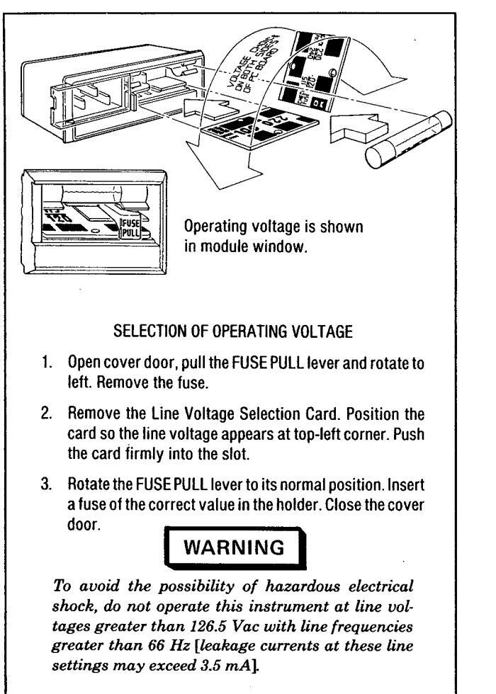
Figure 2-1. Line Voltage and Fuse Selection
Power Cables (cont'd)
cabinet. The power cable plug shipped with each instrument depends on the country of destination. Refer to Figure 2-2 for the part numbers of power cables available.
2-7. HP-IB Address Selection A
In the CW Generator, the HP-IB talk and listen addresses and the parallel poll sense and response line can be selected by internal switches. Refer to Table 2-1 for a listing of talk and listen addresses. The address is factory set for a Talk address of "S" and a Listen address of "3". (In octal this is 23; in decimal this is 19.)
To change the HP-IB address or to select a different parallel poll response, proceed as follows:
WARNINGS
Internal switch settings should be changed only by service trained persons who are aware of the potential shock hazard of working on an instrument with protective covers removed.
To avoid hazardous electrical shock, the line (mains) power cable should be disconnected before attempting to change any internal switch settings.
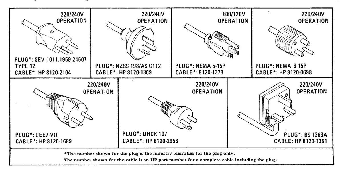
Figure 2-2. Power Cable and Mains Plug Part Numbers

Table 2-1 Allowable HP-18 Address Codes
| Address Swit | ches (Octal) |
Talk
Address Char- |
Listen
Address Char- |
Decimal
Equiva- Ient |
|---|---|---|---|---|
| 51 | 52 | duiti | CD | |
| 0 | 0 |
س
۸ |
1 | |
| 0 | - A | ! | ||
| 0 | 2 | 0 | # | 2 |
| 0 | 3 |
т
с |
||
| 0 | 4 |
۵/ |
||
| 0 | 5 | 70 | 6 | |
| 0 | b | ~~ , | 7 | |
| 0 | 1 | |||
| 1 | 0 | Н | ( | 8 |
| 1 | 1 | ) |
y
to |
|
| 1 | 2 | J | 10 | |
| 1 | 3 | K | + | 11 |
| 1 | 4 | 12 | ||
| 1 | 5 | M | _ | 13 |
| 1 | 6 | N | • | 14 |
| 1 | 7 | 0 | 1 | 15 |
| 2 | 0 | Р | 0 | 16 |
| 2 | 1 | Q | 1 | 17 |
| 2 | 2 | R | 2 | 18 |
| 2 | 3 | S. | 3 | 19 |
| 2 | 4 | Т | 4 | 20 |
| 2 | 5 | U | 5 | 21 |
| 2 | 6 | V | 6 | 22 |
| 2 | 7 | W | 7 | 23 |
| 3 | 0 | Х | 8 | 24 |
| 3 | 1 | Y | 9 | 25 |
| 3 | 2 | Z | : | 26 |
| 3 | 3 | [ | ; | 27 |
| 3 | 4 | < | 28 | |
| 3 | 5 | = | 29 | |
| 3 | 6 | 0 | > | 30 |
HP-IB Address Selection (cont'd)
a. Set the LINE switch to STANDBY. Disconnect the line power cable.
b. Remove the CW Generator's top cover by removing the two plastic standoffs from the rear of the top cover and loosening the screw at the middle of the rear edge of the top cover. Then remove the A2 Assembly's protective cover. Refer to the Disassembly Procedures in Section VIII, Service Sheet A.
c. Select the new address as shown in Table 2-1. The switches are shown in Figure 2-3. The HP-IB ADDRESS SELECT switch settings (for S1 and S2) are in the octal code. For example, the factory selected addresses are set to 23 (decimal 19). Therefore, the listen address is '3' and the talk address is 'S'.
d. If the parallel poll sense or response switches are to be changed, remove any HP-IB cables or connectors from the HP-IB connector, and remove the HP-IB connector. Then remove the A2A9 Board Assembly.
e. The PARALLEL POLL SENSE switch (S4) is set to either the OFF, 0 (zero) or 1 (one) position. The zero position provides a false (+2.5 to 5 volts) output on the asserted HP-IB data line; the one position provides a true (0 to +0.4V) output on the asserted HP-IB data line.
f. The PPR (Parallel Poll Response) switch (S3) is set to select one of eight lines (one of 1 through 8 of the HP-IB data bus). The selected line passes the CW Generator's parallel poll response to the HP-IB controller.
g. Re-install the A2A9 Assembly and HP-IB connector.
h. Replace the A2 Assembly's internal cover, the instrument's top cover, and rear standoffs.
| Part Land | 1. Languel | the hast a second | A 14 . A . A . |
|---|---|---|---|
| 11 11 | 4 1 / 1 | 1. (1.1.) | 1 |
| S1 |
\
$2 |
||
| S1 | Š2 |
Figure 2-3. HP-IB Address Switches Shown as Set by the Factory
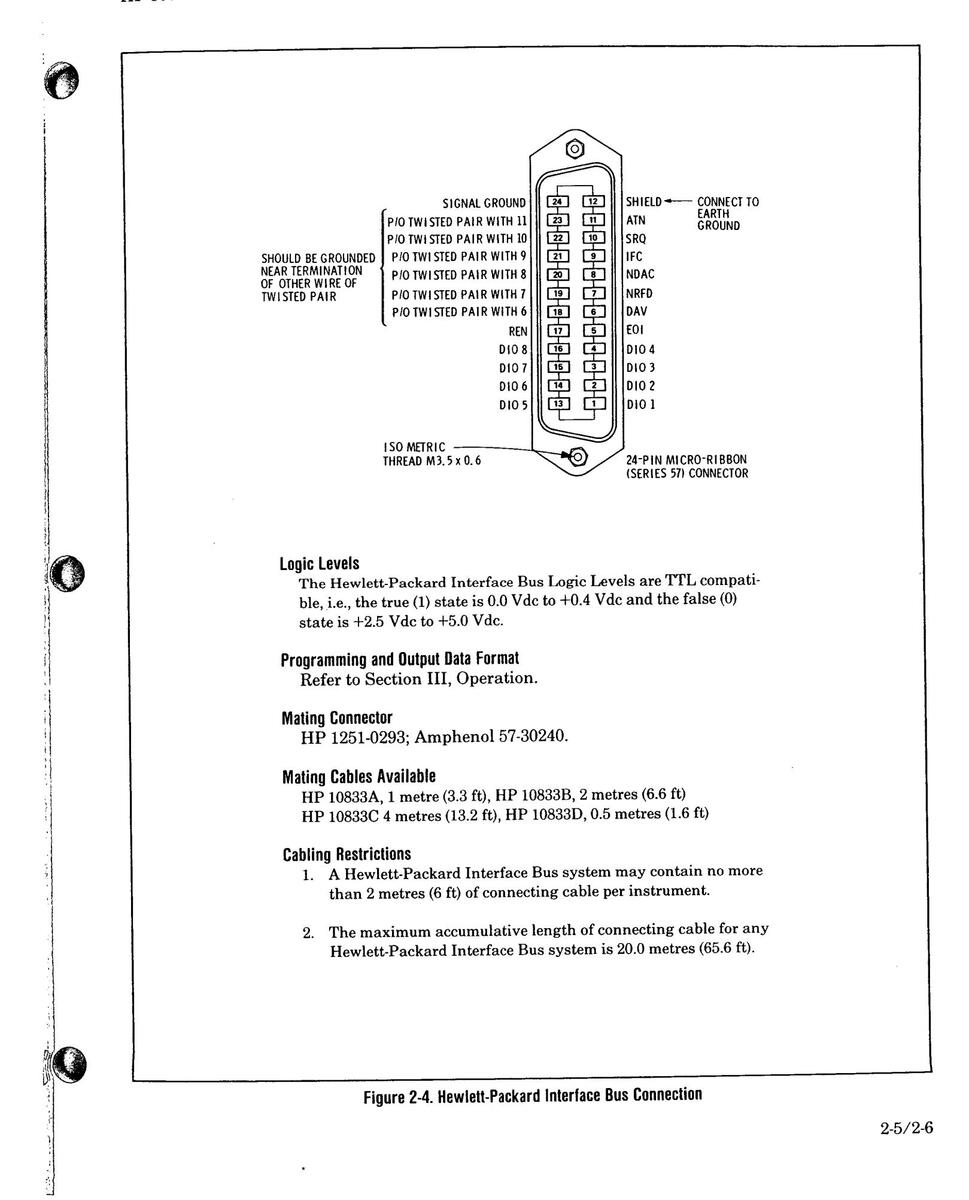
2-8. Interconnections
Interconnection data for the Hewlett-Packard Interface Bus is provided in Figure 2-4.
2-9. Mating Connectors
HP-IB Interface Connector. The HP-IB mating connector is shown in Figure 2-4. Note that the two securing screws are metric.
Coaxial Connectors. Coaxial mating connectors used with the CW Generator RF output should be 500 Type N male connectors.
2-10. Operating Environment
The operating environment should be within the following limitations:
0

Operating Environment (cont'd)
| Temperature | 0 to +55°C |
|---|---|
| Humidity | |
| Altitude | <4570 metres (15,000 feet) |
NOTE
Specifications for RF Output apply only between +15 and +35°C.
2-11. Bench Operation
The instrument cabinet has plastic feet and foldaway tilt stands for convenience in bench operation. (The plastic feet are shaped to ensure selfaligning of the instruments when stacked.) The tilt stands raise the front of the instrument for easier viewing of the front panel.
2-12. Rack Mounting
WARNING
The CW Generator weighs 27.2 kg (60 lbs), therefore extreme care must be exercised when lifting to avoid personal injury. Use equipment slides when rack mounting the instrument.
Rack mounting information is provided with the rack mounting kits. If the kits were not ordered with the instrument as options, they may be ordered through the nearest Hewlett-Packard office. Refer to the paragraph entitled Mechanical Options in Section I.
2-13. STORAGE AND SHIPMENT
2-14. Environment
The instrument should be stored in a clean, dry environment. The following environmental limitations apply to both storage and shipment:
| Temperature | 55 to +75°C |
|---|---|
| Humidity | |
| Altitude | 15,300 metres (50,000 feet) |
2-15. Packaging
Preparation for Packaging. Remove handles and/or rack mount flanges before packaging instrument for shipping.
Tagging for Service. If the instrument is being returned to Hewlett-Packard for service, please complete one of the blue repair tags located at the back of this manual and attach it to the instrument.
Original Packaging. Containers and materials identical to those used in factory packaging are available through Hewlett-Packard offices. Mark the container "FRAGILE" to assure careful handling. In any correspondence refer to the instrument by model number and full serial number.
Other Packaging. The following general instructions should be used for re-packaging with commercially available materials:
a. Wrap the instrument in heavy paper or plastic. (If shipping to a Hewlett-Packard office or service center, complete one of the blue tags mentioned above and attach it to the instrument.)
b. Use a strong shipping container. A doublewall carton made of 2.4 MPa (350 psi) test material is adequate.
c. Use enough shock-absorbing material (75 to 100 mm layer; 3 to 4 inches) around all sides of the instrument to provide firm cushion and prevent movement in the container. Protect the front panel with cardboard.
d. Seal the shipping container securely.
e. Mark the shipping container "FRAGILE" to assure careful handling.

SECTION III OPERATION
3-1. INTRODUCTION
This section provides complete operating information for the CW Generator. Included are both simplified and detailed operating instructions, detailed descriptions of the front and rear panel, local and remote operator's checks, and operator's maintenance.
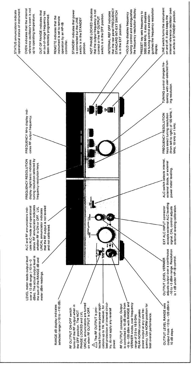
3-2. Panel Features
Front and rear panel features are described in detail in Figures 3-1 and 3-2.
3-3. Operating Characteristics
Table 3-1 briefly summarizes the major operating characteristics of the CW Generator. This table is not intended to be a complete listing of all operations and ranges, but gives a general idea of the instrument's capabilities. For more information on the CW Generator's capabilities, refer to Table 1-1, Specifications, and Table 1-2, Supplemental Characteristics. For information on HP-IB capabilities, refer to Table 3-3, Message Reference Table.
3-4. Local Operation
Information covering front panel operation of the CW Generator is given in the sections described below. To quickly learn the operation of the instrument, begin with Operating Characteristics and Simplified Operation. (Operator's Checks can also be used to gain familiarity with the instrument.) Once familiar with the general operation of the instrument, use the Detailed Operating Instructions as a reference for more complete operating information.
Turn-On Information. Instructions relating to the CW Generator turn-on procedure and frequency standard selection are presented to acquaint the user with the general operation of the instrument.
Simplified Operation. The instructions located on the inside of the fold provide a quick introduction to the operation of the CW Generator. In addition, an index to the Detailed Operating Instructions
is provided to direct the user to the more complete discussion of the topic of interest.
Detailed Operating Instructions. The Detailed Operating Instructions provide the complete operating reference for the CW Generator user. The instructions are organized alphabetically by subject. They are indexed by function in Table 3-2.
3-5. Remote (HP-IB) Operation
The CW Generator is capable of remote operation via the Hewlett-Packard Interface Bus (HP-IB).
HP-IB is Hewlett-Packard's implementation of the IEEE Standard 488, "IEEE Standard Digital Interface for Programmable Instrumentation", also described by the identical ANSI Standard MC1.1. For a more detailed information relating to programmable control of the CW Generator, refer to Remote (HP-IB) Operation in this section.
This section includes discussions on capabilities, addressing, input and output formats, the status byte and service request. In Table 3-4 is a complete summary of programming codes. In addition, programming examples are given in HP-IB Checks and in the Detailed Operating Instruction.
3-6. Operator's Checks
Operator's Checks are procedures designed to verify proper operation of the CW Generator's main functions. Two procedures are provided as described below.
Basic Functional Checks. This procedure requires only a 50 ohm load or attentuator to perform. For greater assurance, a microwave counter and a power meter can be used. This procedure assures that most front panel controlled functions are being properly executed by the CW Generator.
HP-IB Checks. This procedure assumes that front panel operation has been verified with the Basic Functional Checks. The procedure checks all of the applicable bus messages summarized in Table 3-3.
3-1
| Frequency |
Range: 2.0 to 18.0 GHz
(Overrange to 18.599997 GHz) |
|||
|---|---|---|---|---|
| Resolution: 1 kHz 2.0 to 6.2 GHz | ||||
| 2 kHz 6.2 to 12.4 GHz | ||||
| 3 kHz 12.4 to 18.0 GHz | ||||
| Output Level | Range: -120 to +8 dB in 10 dB steps | |||
| Vernier: -10 to +3 dBm continuously variable | ||||
| ALC | Internal, external crystal detector, or external power meter leveling. | |||
Table 3-1. Operating Characteristics
Table 3-2. Index of Detailed Operating Instructions
| 3-14 | ALC CONTROL | |
| Local Procedure | 3-4 | |
| Internal Leveling | 3-4 | |
| External Crystal Detector Leveling | 3-4 | |
| External Power Meter Leveling | 3-4 | |
| Remote Procedure | 3-5 | |
| Comments | 3-7 | |
| 3-15 | FREQUENCY CONTROL | 3-8 |
| Local Procedure | 3-8 | |
| Remote Procedure | 3-8 | |
| Comments | 3-10 | |
| 3-16 | LEVEL CONTROL | 3-12 |
| Local Procedure | 3-12 | |
| Remote Procedure | 3-12 | |
| Comments | 3-13 | |
| 3-17 | PEAK-NORM ADJUSTMENT | 3-15 |
| Local Procedure | 3-15 | |
| Comments | 3-15 | |
| 3-18 | RF ON-OFF SWITCH | 3-16 |
| 0 10 | Local Procedure | 3.16 |
| Remote Procedure | 3.16 | |
| Comments | 3-16 | |
3-7. Operator's Maintenance
WARNING
For continued protection against fire hazard, replace the line fuse with a 250V fuse of the same rating only. Do not use repaired fuses or short-circuited fuseholders.
Operator's maintenance consists of replacing defective primary fuses. This fuse is located in the line module assembly. Refer to Figure 2-1 for instructions on changing the fuse.
3-8. TURN-ON INSTRUCTIONS

efore the instrument is switched on, all protective earth termi-1als, extension cords, autotransformers and devices connected to it should be connected to a protective earth grounded socket. Any interruption of the protective earth Brounding will cause a potential shock hazard that could result in personal injury.
Only 250V normal blow fuses with the required rated current should be used. Do not use repaired fuses or short circuit fuseholders. To do so could cause a shock or fire hazard.

Before the instrument is switched on, it must be set to the voltage of the power source or damage to the instrument may result.
A The CW Generator's RF OUTPUT is protected against reverse power applications up to 1W. However, for greatest protection of expensive internal components, be careful not to apply any reverse power to the RF OUTPUT.
3-9. Turn-On
Turn-On Procedure. The CW Generator has a STANDBY state and an ON state. Whenever the power cable is plugged in, an oven is energized to keep the reference oscillator at a stable operating temperature. If the CW Gener-ator is already plugged in, set the LINE switch to ON.
If the power cable is not plugged in, follow these instructions.
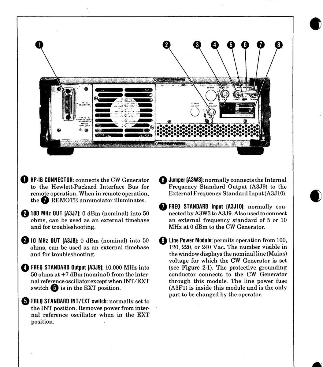
On the rear panel:
- Check the line voltage switch for correct voltage selection.
- 2. Check that the fuse rating is appropriate for the line voltage used (see Figure 2-1).
- Plug in the power cable.
On the front panel, set the LINE switch to ON.
NOTE
The OVEN status annunciator should light to indicate that the CW Generator requires warming up. The annunciator should turn off within fifteen minutes and the CW Generator should be ready for general use.
Furn-On Configuration . The CW Generator turns on at the same frequency as before it was switched to STANDBY or even completely off (that is, if line
3-10. Frequency Standard Selection
A FREQ STANDARD INT/EXT switch and two connectors are located on the rear panel. A jumper normally connects the FREQ STANDARD INT connector (A3J9) to the FREQ STANDARD EXT connector (A3J10). The
requency Standard Selection (cont'd)
FREQ STANDARD EXT connector can accept a reference signal to be used instead of the CW Generator's internal reference oscillator.
When the FREQ STANDARD INT/EXT switch is in the INT position and the jumper is connected between A3J9 and A3J10, the internal reference scillator is enabled.
When the FREQ STANDARD INT/EXT switch is in the EXT position and the jumper is disconnected from the FREQ STANDARD EXT connector, a requency standard of 5 or 10 MHz at 0 dBm (nominal) can be connected.
the INTERNAL REF OFF status annunciator on the front panel will light when an external reference is being used. Also, the NOT PHASE LOCKED status annunciator may light if the external reference is not of sufficient accuracy in frequency or has an insufficient power level. The external reference must be within -200 Hz of 10 MHz or ±100 Hz of 5 MHz for reliable locking to occur. If the external reference level is not within the specified limits (0.1 to 1 Vrms into 50 ohms), its level may be sufficient to urn off the NOT PHASE LOCKED status annunciator. However. he phase noise of the CW Generator may be degraded.
Operation FRONT PANEL FEATURES
Ô
3-11. SIMPLIFIED OPERATION
3-12. Frequency
Frequency is set using the FREQUENCY RESO-LUTION keys and the TUNING knob. For example, to set the frequency to 15345.678 MHz:
Press PRESET (3 GHz). This is not always necessary, but it will set the right-hand six digits to 0, and may provide a convenient starting point.
Select the 100 MHz FREQUENCY RESOLUTION key and adjust the TUNING knob for a frequency of 15300.000 MHz.
Select the 1 MHz FREQUENCY RESOLUTION key and adjust the TUNING knob for a frequency of 15345.000 MHz. Select the 10 kHz FREQUENCY RESOLUTION key and adjust the TUNING knob for a frequency of 15345.670 MHz.
Select the 1 kHz FREQUENCY RESOLUTION key and adjust the TUNING knob for a frequency of 15345.678 MHz.
Press HOLD to disable the TUNING knob.
3-13. Output Level
The output level is set with the OUTPUT LEVEL RANGE and VERNIER controls.
First, adjust RANGE to step the output level up or down by increments of 10 dB. The selected range is shown in the RANGE dB display.
Adjust VERNIER between -10 and +3 dBm, as read on the meter, for the desired output level.
The output level is determined by adding the RANGE dB display to the LEVEL dBm meter reading.
3-14. ALC
ALC (automatic level control) has three modes of operation. They are:
INT (Internal leveling)
- XTAL (External leveling using a crystal diode detector)
- PWR MTR (External leveling using a power meter)
Internal leveling is selected for most applications. In this mode, an internal detector senses the level at the input of the 10 dB step attenuator, and the internal leveling circuitry keeps the output level constant. Loss of leveling is indicated by the LVL UNCAL annunciator.
For external leveling a crystal diode detector or power meter can be used. Operation is described further in the Detailed Operating Instructions.
3-15. ALC CONTROL
Description
Local
Procedure
tion The Synthesized CW Generator has three modes of Automatic Level Control (ALC):
INT (Internal leveling) XTAL (External leveling using a crystal diode detector) PWR MTR (External leveling using a power meter)
For most applications internal ALC (INT) will be used. With internal ALC the output power remains flat over the entire 2 to 18 GHz frequency range.
External ALC is used when the power level at a remote point must be kept constant. External ALC reduces power variations due to external cables and connectors.
The ALC switch selects the leveling mode. Positive or negative detectors can be used to supply the external ALC input voltage. A calibration adjustment allows the externally leveled power to be adjusted to match the VERNIER setting over a limited output power range. The calibration adjustment does not affect internal leveling
ALC mode and status are indicated by the ALC display. The display indicates which leveling source is selected and when the output is unleveled. The status of the ALC, whether leveled or unleveled, can also be determined remotely by reading the status byte.
To use Internal Leveling:
Set the ALC selector to INT. The output level will be the sum of the range and VERNIER settings.
To use XTAL (External Crystal) Leveling:
- 1. Connect the crystal detector and the 10 dB coupler as shown in Figure 3-3.
- 2. Set the ALC selector to INT and adjust the VERNIER to read 0 dBm on the meter. This allows calibration of the meter to the leveled point.
- 3. Set the output level range to 0 dB and the ALC selector to XTAL.
- 4. Adjust the ALC CAL control to set the level read on the power meter to the nearest 10 dBm. If the ALC control does not have enough range for a low power level adjustment, step the RANGE down until the adjustment can be made.
This level should be within -3 dB and +10 dB of the desired level. This calibrates the meter to agree with the leveled power. If the detector is operating in the square law
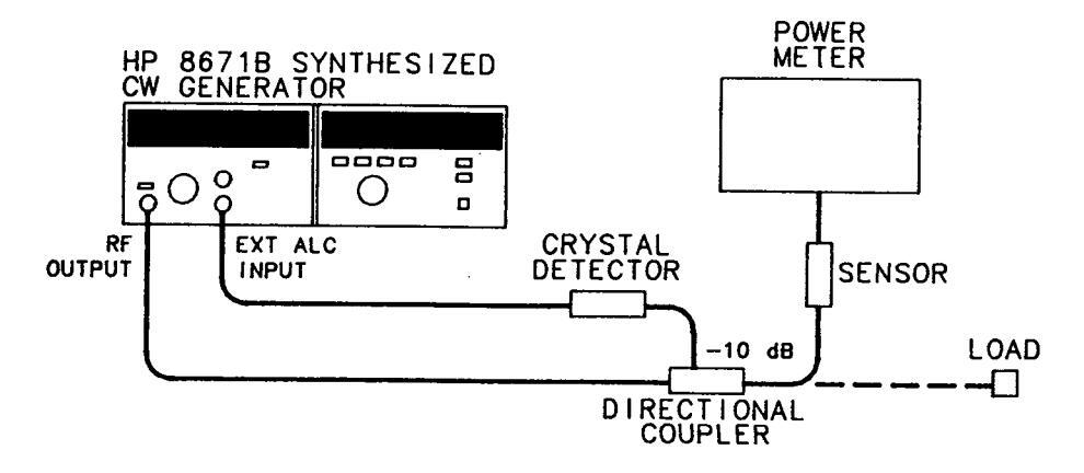
Figure 3-3. External Leveling with a Crystal Detector
ALC CONTROL (cont'd)
Local Procedure (cont'd)
region, the VERNIER will now control the level over a continuous 13 dB range, and the CW Generator's meter reading will track with the power meter reading as the VERNIER control is varied through the -10 to +3 dBm range.
To use external power meter leveling:
- 1. Set the ALC selector to INT and adjust the VERNIER to read 0 dBm on the meter. This allows calibration of the CW Generator's meter to the leveled point.
- 2. Connect power meter to the point where leveling is to be used as shown in Figure 3-4. A directional coupler can be used to sample the power at the desired point. Set the output level to the desired power and select the range hold function on the power meter. This disables range changes and keeps the leveled power from oscillating.
- 3. Connect the recorder output of the power meter to the external ALC input connector. The recorder output is a voltage that is proportional to the measured power in watts. This voltage varies from 0 to 2 volts for each power meter range. Leveling as low as -60 dBm can be accomplished with a sensitive power sensor using this method.
- 4. Set the output level range to 0 dB and the ALC selector to PWR MTR.
- 5. Adjust the ALC CAL controls to set the level read on the power meter to the nearest 10 dBm. This level should be within -3 dB and +10 dB of the desired level (minus the coupling factor of the directional coupler). This calibrates the CW Generator's meter to agree with the leveled power. This power leveling method has a slow settling time but has the advantage of high sensitivity and temperature compensation.
If the ALC CAL control does not have enough range for a low power level adjustment, step the RANGE down until the adjustment can be made.
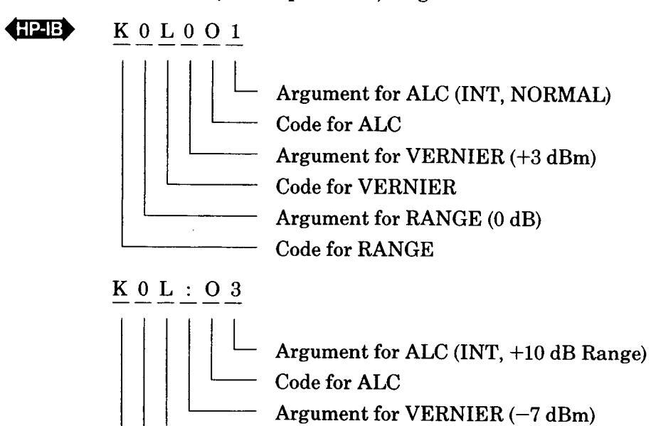
Remote Procedure
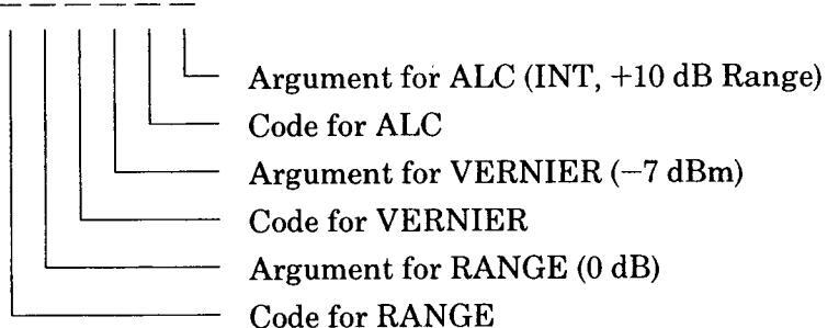
The ALC program code controls the function of the RF output ON/OFF switch, the ALC selector and the +10 dB range of output power. The program string consists of the letter O followed by a single argument representing the desired combination of the control positions.
To set the CW Generator to the +10 dB range, you must first set it to 0 dB with the range command (code and argument) K0. Then you can set the +10 dB range with the appropriate ALC command.
The codes are summarized in the table under Program Codes.
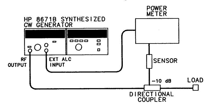
Figure 3-4. External Leveling with a Power Meter
ALC CONTROL (cont'd)
Example
To set internal ALC with an output level of +3 dBm:
Local
Set ALC selector to INT, RF output to ON, range to 0 dB and VERNIER for +3 dBm.
Set ALC selector to INT, RF output to ON, range to +10 dB and VERNIER to -7 dBm.
— Code for VERNIER
— Argument for RANGE (0 dB)
- Code for RANGE
| Deseure Onde | ALC Mode | |||
|---|---|---|---|---|
| rrogram Gode | RF | RANGE | ALC | Argument |
| OFF | NORM |
INT
XTAL PWR MTR |
0
4 < |
|
| OFF | +10 |
INT
XTAL PWR MTR |
2
6 > |
|
| (letter O, not zero) | NORM |
INT
XTAL PWR MTR |
1
5 = |
|
| ON | +10 |
INT
XTAL PWR MTR |
3
7 ? |
|
| _ | ||
|---|---|---|
| Program | Codes | HP-IB |
ALC CONTROL (cont'd)
Comments
Output level flatness is dependent on the ALC circuitry and the maximum available power. In order to have a leveled output it is necessary for the ALC circuitry to continuously control the output level. This can only occur if the selected output power is below the maximum power level available at each frequency. For leveled output power in the +10 dB range, it is necessary that the LVL UNCAL annunciator remain off.
External ALC leveling also requires that the CW Generator can produce enough power to overcome losses in the intervening circuitry. The LVL UNCAL annunciator must remain off to achieve leveling. The 0 dB range should be used when using external leveling. If any of the lower ranges are used, the CW Generator must produce a higher level to overcome the attenuation introduced by the range selected.
For output level settings above +8 dBm, spurious oscillations can occur, resulting in sidebands on the carrier at a level of 30 to 50 dBc. These oscillations occur only over small portions of the frequency range. They can usually be eliminated by performing a PEAK-NORM adjustment or by reducing the output level VERNIER setting 1 or 2 dB.
Typical output level switching times are detailed under Level Control. Enabling the RF output requires less than 30 milliseconds. Disabling the RF output can be accomplished in less than 5 milliseconds.
The state of the RF output (on or off) and the status of the +10 dB range (selected or not selected) can be obtained by reading the status byte. The status of the ALC circuitry (leveled or not leveled) can also be monitored by reading the status byte. Once the status byte indicates that the output is leveled, an application can continue without waiting the specified time for the output level to settle.
Related Sections
Level Control PEAK-NORM Adjustment
3.16 FREQUENCY CONTROL
Description The CW Generator uses a simple, convenient frequency tuning system.
All frequencies can be remotely programmed or entered manually by a tuning knob. The knob can be turned in either direction without encountering a mechanical stop. Also, the faster it is turned the greater the frequency change per revolution.
In addition, four degrees of coarse to fine tuning can be selected. Frequency resolution keys located above the tuning knob select 100 MHz, 1 MHz, 10 kHz or 1 kHz tuning increments. Due to frequency multiplication to generate frequencies above 6.2 GHz, the minimum tuning increment (resolution) is 2 kHz above 6.2 GHz and 3 kHz above 12.4 GHz.
Once a desired frequency has been set, pressing the HOLD key will disable the tuning control and prevent unintentional changes in the frequency. The preset key sets the output frequency to 3000.000 MHz for conveniently setting the least significant digits to zeroes.
When the CW Generator is turned off or the power cable is removed, the last frequency setting is stored in battery-powered memory. When the instrument is powered up, the frequency returns to the stored value. This feature maintains the frequency setting even after power failures or extended periods without power.
Local Procedure
To set the output frequency to any desired frequency:
- 1. Press PRESET (3 GHz). This is not always necessary, but it will set the right-hand six digits to 0, and may provide a convenient starting point.
- 2. Select the desired tuning increment (100 MHz, 1 MHz, 10 kHz, or 1 kHz) by pressing the appropriate FREQUENCY RESOLUTION key, and use the TUNING knob to set the frequency digits above the rightmost lighted segment in the frequency resolution display.
- 3. Once the desired frequency is set, press the HOLD key to disable the TUNING knob.
RemoteThe CW Generator accepts any frequency within its range (2000.000 to 18599.997 MHz)Procedureto 8 significant digits. Above 6.2 GHz the frequency is randomly rounded up or down to<br/>be compatible with the 2 kHz or 3 kHz resolution at the programmed frequency.
The CW Generator ignores spaces, commas, decimal points, carriage returns and line feeds.
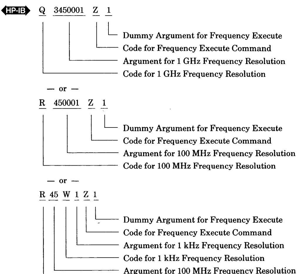
Within the CW Generator, frequency information is stored in two separate blocks of four digits each. The effects of programming codes on the two internal frequency data blocks are shown in Figure 3-5. One block contains the 10 GHz through 10 MHz frequency digits and the other contains the 1 MHz through 1 kHz digits. Programming within one block does not change the other blocks unless it is necessary to round off a frequency above 6.2 GHz. The programming codes indicate the most significant digit being programmed.
The output frequency does not change until the frequency execute command (Z1) is received by the CW Generator. This command must be sent sometime after the frequency data has been sent.

Frample
To change frequency from 3000.231 MHz to 3450.001 MHz:
Local
- Press the 100 MHz (leftmost) FREQUENCY RESOLUTION key. Adjust TUNING for a frequency of 3400.000 MHz.
- 2. Press the 1 MHz (next) FREQUENCY RESOLUTION key. Adjust TUNING for a frequency of 3450.000 MHz.
- 3. Press the 1 kHz (rightmost) FREQUENCY RESOLUTION key. Adjust TUNING for a frequency of 3450.001 MHz.
————————————————————————————————————
| PROGRAM ( | CODES | ARGUMENTS | |
|---|---|---|---|
| FREQUENCY |
10 GHz
1 GHz 100 MHz 10 MHz 1 MHz 100 kHz 100 kHz 1 kHz EXECUTE |
@ or P
A or Q B or R C or S D or T E or U F or V G or W J or Z |
0 THROUGH 9 |
Program Codes
FREQUENCY CONTROL (cont'd)
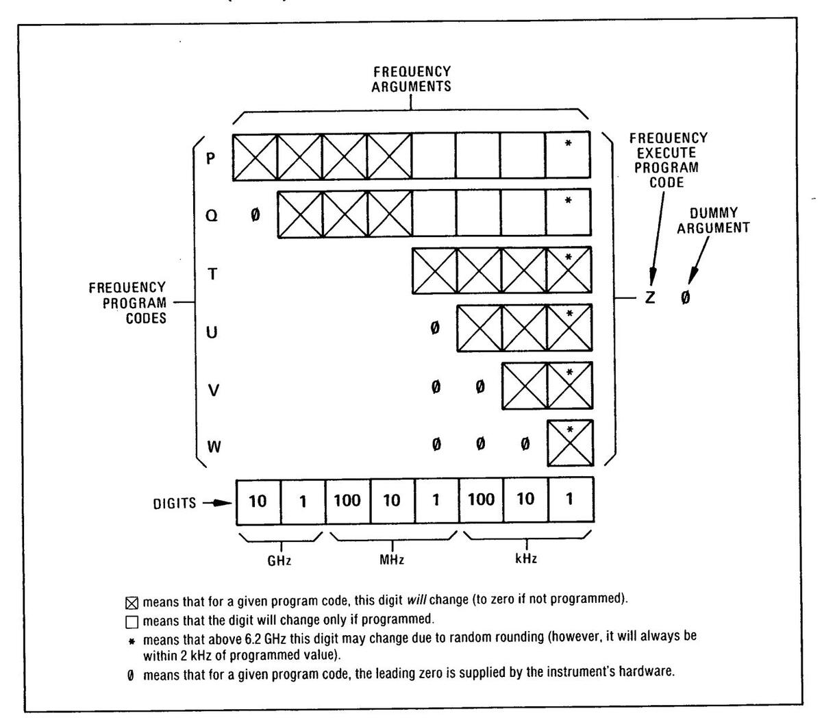
Figure 3-5. Frequency Programming Codes and Arguments
Comments Due to the use of frequency multiplication to generate frequencies above 6.2 GHz, the frequency sometimes cannot be set precisely to a desired value. Frequencies between 2 and 6.2 GHz can be set to the nearest 1 kHz. All frequencies between 6.2 and 12.4 GHz can be set within 1 kHz of the desired value. All frequencies between 12.4 and 18 GHz can be set within 2 kHz of the desired frequency.
When the CW Generator is programmed to a frequency that is not evenly divisible, a random roundoff occurs. To prevent this, remote programming one should perform a calculation to determine whether the frequency can be set exactly.
To determine whether a frequency can be set to a given value, divide the desired frequency (in kHz) by two if it is between 6.2 and 12.4 GHz, or by three if it is above 12.4 GHz. IF the result is a whole number (with no remainder) the frequency can be set to the

C
FREQUENCY CONTROL (cont'd)
Comments (cont'd)
desired value. For example, 16 GHz divided by three (it is above 12.4 GHz) is 5333333.33 kHz, so this frequency cannot be set exactly. The nearest frequencies that can be set are 15.999999 GHz (5.333333 × 3) and 16.000002 GHz (5.333334 × 3).
The time it takes to switch from one frequency to the next depends on the largest frequency digit being changed. Generally, the smaller the digit being changed, the shorter the switching time. Typical switching times by largest digit being changed for frequencies between 2 and 6.2 GHz can be summarized as follows:
|
Largest Digit
Changed |
Time to be
Within 1 kHz |
|---|---|
| 100 MHz | 10 ms |
| 10 MHz | 10 ms |
| 1 MHz | 10 ms |
| 100 kHz | 5 ms |
| 10 kHz | 3 ms |
| 1 kHz | 1.5 ms |
For frequencies above 6.2 GHz, actual frequency digits being changed must be determined by dividing the output frequency by two (6.2 to 12.4 GHz) or three (12.4 to 18 GHz). The actual data transfer time is only a small portion of the frequency switching time and can be ignored.
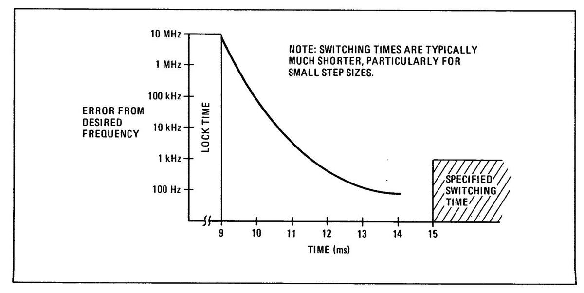
For applications that require fast execution, the status byte can be checked until the frequency is phase locked. Once the status byte indicates that the CW Generator is phase locked, the application may continue with the assurance that the frequency is correct. Figure 3-6 shows the typical worst case lock and settling times.

1
3-17. LEVEL CONTROL
Description The Synthesized CW Generator is calibrated over a wide range of output power levels from +8 dBm to -120 dBm. The output level is set with a RANGE selector and a VERNIER control. The output level is the sum of the settings of these two controls.
The RANGE selector varies the output level in 10 dB steps. The selected range (+10 dB to -110 dB) is digitally displayed in the RANGE display. This display indicates the selected range in both local and remote modes. Output level ranges of 0 dB to -110 dB are programmable with the range program code. The +10 dB range is selected using the ALC program code.
The VERNIER knob continuously varies the output level in the 0 dB range from -10 to +3 dBm. The VERNIER setting is indicated by the front panel meter.
In local mode the VERNIER can be varied continuously over the full 13 dB range. In remote mode the VERNIER can be programmed in fourteen 1 dB steps from -10 dBm to +3 dB. Because the VERNIER can be controlled over greater than 10 dB in both local and remote mode, it is possible to overlap range settings by 3 dB. This is useful in applications where the ability to vary the output power continuously about a given level is critical.
Local To set the output level to any desired value:
Procedure
- 1 Set the CW Generator ALC mode to internal (INT).
- 2. Set the OUTPUT LEVEL RANGE to within -3 to +10 dB of the desired output level. For example, for a -56 dBm output level choose the -50 dB range.
- 3. Adjust the OUTPUT LEVEL VERNIER setting until the sum of the range display and the meter is equal to the desired output level.
Some output levels may be set using either of two adjacent ranges. Either range may be used. For example, +3 dBm may be set with a 0 dB range and +3 dBm VERNIER setting or a +10 dB range and -7 dBm VERNIER setting.
Setting output levels above +8 dBm may cause an ALC unleveled condition due to insufficient power available. The meter will indicate the actual power available when the unleveled condition occurs.
RemoteThe 0 dB to -110 dB ranges and the VERNIER setting are programmed with the output<br/>level program codes. The VERNIER setting is programmed in 1 dB steps from -10 dBm<br/>to +3 dBm. The range is programmed in 10 dB steps from 0 dB to -110 dB. The +10 dB<br/>range is programmed by setting RANGE to 0 dBm and ALC to +10 dB.
When switching from local to remote mode, the VERNIER is reset to -10 dB and the range remains unchanged.
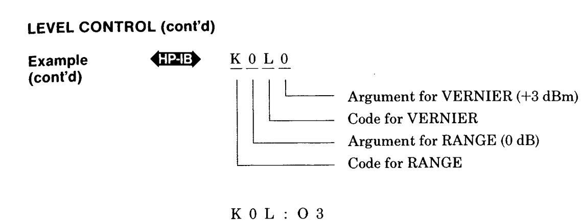
Example To set the output level to +3 dBm:
Local
Set RANGE to 0 dB and VERNIER to +3 dBm.
Or
Set RANGE +10 dB and VERNIER to -7 dBm.
| ſ | Program Codes | Argumen | its | Program Codes | Argumen | its | |
|---|---|---|---|---|---|---|---|
| OUTPUT LEVEL RANGE | К |
0 dBm
-10 -20 -30 -40 -50 -60 -70 -80 -90 -100 -110 |
0
1 2 3 4 5 6 7 8 9 : ; |
OUTPUT LEVEL VERNIER | L |
+3 dB
+2 +1 0 -1 -2 -3 -4 -5 -6 -7 -8 -9 -10 |
0
1 2 3 4 5 6 7 8 9 :; < = |
Comments Output level flatness is dependent on the ALC circuitry and the maximum available power. In order to have a leveled output it is necessary for the ALC circuitry to continuously control the output level. This can only occur if the selected output power is below the maximum power level available at each frequency. For leveled output power in the +10 dB range, it is necessary that the LVL UNCAL annunciator remain off. If it lights, adjust the PEAK-NORM control, or reduce the VERNIER setting.
For output level settings above +8 dBm, spurious oscillations can occur, resulting in sidebands on the carrier at a level of 30 to 50 dBc. These oscillations occur only over small portions of the frequency range.
Program Codes
LEVEL CONTROL (cont'd)

Comments (cont'd) They can usually be eliminated by performing a PEAK-NORM adjustment or by reducing the OUTPUT LEVEL VERNIER setting 1 or 2 dB.
External ALC leveling also requires that the CW Generator can produce enough power to overcome losses in the intervening circuitry. The LVL UNCAL annunciator must remain off to achieve leveling. If it lights adjust the PEAK-NORM control, or decrease the the VERNIER setting.
Typical output level range change execution time for a 10 dB step is less than 20 milliseconds. An output level VERNIER change of 1 dB will take less than 10 milliseconds. These times are typical for remote programming. The actual data transfer time is a very small part of the execution time and may be ignored for most controllers.
The RF output changing from enabled to disabled takes less than 5 milliseconds. To enable the RF output from a disabled state requires less than 30 milliseconds.
The state of the RF output (on or off) and the +10 dB range (selected or not selected) can be obtained by reading the status byte. These two functions are programmed along with the ALC mode. For more information see ALC Control.
RelatedALC ControlSectionsPEAK-NORM Adjustment
3-18. PEAK-NORM ADJUSTMENT
Description The PEAK-NORM control adjusts an internal filter for maximum power output at a single frequency. This filter is adjusted for best over-all performance with the control in the detent position (NORM), but can be adjusted for maximum power (and reduced harmonics and sub-harmonics) at any one frequency. This adjustment will result in lower maximum power at most other frequencies, and therefore should be left in the NORM position except when maximum power is needed. It should only be required at power levels above +8 dBm.
To maximize the output power at a set frequency:
This adjustment cannot be remotely programmed
Adjust the PEAK-NORM adjustment until the LVL UNCAL annunciator turns off, or for maximum meter reading with the VERNIER fully clockwise.
Remote Procedure
Dracedure
Local
Example To peak an output level of +10 dBm at 8 GHz due to a LVL UNCAL indication:
- 1. Adjust the PEAK-NORM adjustment until the LVL UNCAL annunciator turns off, or for maximum meter reading with the VERNIER fully clockwise.
- 2. Return the PEAK-NORM adjustment to NORM (detented) position before resuming normal instrument operation. The +8 dBm output power level is affected by this adjustment and is only specified with the PEAK-NORM adjustment set to NORM.
Comments
For output level settings above +8 dBm, spurious oscillations can occur, resulting in sidebands on the carrier at a level of 30 to 50 dBc. These oscillations occur only over small portions of the frequency range.
They can usually be eliminated by performing a PEAK-NORM adjustment or by reducing the output level VERNIER setting 1 or 2 dB.
The PEAK-NORM adjustment must be in the NORM (detented) position to guarantee the specified +8 dBm level over the entire frequency range.
1
3-19. RF ON/OFF SWITCH
seconds.
| Description |
The RF ON/OFF switch provides a convenient way of turning off the output signal.
This is useful when calibrating detectors, zeroing power meters, or making noise mea- surements with no signal applied. With the switch in the off position the internal 2 to 6.2 GHz oscillator is turned off to prevent any signal leakage to the RF output connector. The RF annunciator indicates the position of the RF ON/OFF switch in local mode and the programmed state when in remote mode. With the internal 2 to 6.2 GHz oscillator turned off, the CW Generator is no longer phase locked or leveled so the LVL UNCAL and NOT PHASE LOCKED annunciators are lighted. |
|---|---|
| Local | To disable the RF output: |
| Procedure | Set the RF ON/OFF switch to OFF. Note that the OFF, LVL UNCAL and NOT PHASE LOCKED annunciators should be lighted. |
| To enable the RF output: | |
| Set the RF ON/OFF switch to ON. The LVL UNCAL and NOT PHASE LOCKED annunciators should extinguish and the ON annunciator should light. | |
|
Remote
Procedure |
See ALC Control for a description of how to program the RFON/OFF switch function. |
|
Program
Codes |
See ALC Control |
| Comments | The status of the RF output (on or off) can be determined by reading the status byte. A service request is not generated for LVL UNCAL or NOT PHASE LOCKED when the RF output is set to OFF. |
| The RF output off-to-on transition typically requires less than 30 milliseconds when remotely programmed. The on-to-off transition typically requires less than 5 milli- |
A
3-20. REMOTE (HP-IB) OPERATION
The CW Generator can be operated through the Hewlett-Packard Interface Bus (HP-IB). HP-IB compatibility, programming and data formats are described in the following paragraphs.
All front panel functions except that of the ALC CAL control, PEAK-NORM control, and LINE switch are programmable via HP-IB.
A quick test of the CW Generator's HP-IB interface is described in this section under HP-IB Checks. These checks verify that the CW Generator can respond to or send each of the applicable bus messages described in Table 3-3.
3-21. HP-IB Compatibility
The CW Generator's programming capability is described by the twelve HP-IB messages listed in Table 3-3. The CW Generator's compatibility with HP-IB is further defined by the following list of interface functions: SH1, AH1, T6, TE0, L4, LE0, SR1, RL2, PP2, DC1, DT0, and C0. A more detailed explanation of these compatibility codes can be found in IEEE Standard 488-1978 and the identical ANSI Standard MC1.1.
3-22. Remote Mode
Remote Capability. The CW Generator communicates on the bus in both remote and local modes. In remote, the CW Generator's front panel controls are disabled except for the LINE switch. However, front panel displays remain active and valid. In remote, the CW Generator can be addressed to talk or listen. When addressed to listen, the CW Generator automatically stops talking and responds to the following messages: Data. Clear (SDC). Remote, Local, and Abort. When addressed to talk, the CW Generator automatically stops listening and sends one of the following messages: Data, Require Service, or Status Byte, Whether addressed or not the CW Generator responds to the Clear (DCL), Clear Lockout/Set Local, and Abort messages. In addition, the CW Generator can issue the Require Service message and the Status Bit message.
Local-to-Remote Mode Changes. The CW Generator switches to remote operation upon receipt of the Remote message. The Remote message has two parts. They are:
a. Remote enable bus control line (REN) set true.
b. Device listen address received once (while REN is true).
When the CW Generator switches to remote, the REMOTE annunciator on the front panel turns on. With the exception of VERNIER, which will reset to -10 dBm, the CW Generator's control settings remain unchanged with the Local-to-Remote transition.
3-23. Local Mode
Local Capability. In local, the CW Generator's front panel controls are fully operational and the instrument will respond to a Remote message. The CW Generator can send a Require Service message, a Status Byte message, and a Status Bit message while in the Local mode.
Remote-to-Local Mode Changes. The CW Generator switches to local from remote whenever it receives a Local (GTL), Universal Unlisten address, Abort, or Clear Lockout/Set Local message. (The Clear Lockout/Set Local message sets the Remote Enable control line [REN] false.) The CW Generator can also be switched to local by turning the LINE switch to STANDBY, and then to ON.
With the Remote-to-Local transition, the frequency will remain the same. All other functions will return to the front panel settings. Power may go up, go down, or stay the same.
3-24. Addressing
When the Remote Enable line (REN) and the Attention control line (ATN) are true and the Interface Clear control line (IFC) is false, the CW Generator interprets the byte on the eight HP-IB data lines as an address or a command.
The CW Generator's Talk and Listen addresses can be set by switches located inside the instrument. The address selection procedure is described in Section II. Refer to Table 2-1 for a comprehensive listing of all valid HP-IB address codes.
3-25. Data Messages
The CW Generator communicates on the interface bus primarily with Data messages. Data messages consist of one or more bytes sent over the bus' data lines when the bus is in the data mode (attention control line [ATN] false). The CW Generator receives Data messages when addressed to listen, and sends the Status Byte message when addressed to talk. All instrument operations available in
Operation
| Table 2.2 | Maccona | Roforance | Table (1 | of 2) |
|---|---|---|---|---|
| 12018 3-3. | MESSAGE | Helerence | 1 JULE I |
|
HP-IB
Message |
Appli-
cable |
Response |
Related
Commands and Controls |
Interface
Functions* |
|---|---|---|---|---|
| Data | Yes |
Frequency, Output level (RANGE and VERNIER), and ALC mode
can be programmed. The CW Generator sends the status byte when addressed to talk. |
AH1
SH1 T6, TE0 L4, LE0 |
|
| Trigger | No |
The CW Generator does not respond to the Group Execute Trigger
(GET) bus command |
GET | DT0 |
| Clear | Yes |
Sets frequency to 3000.000 MHz, RF output to off, ALC mode to
Internal, and VERNIER to –10 dBm. |
DCL
SDC |
DC1 |
| Remote | Yes |
Remote mode is enabled when the REN bus control line is true.
However, remote mode is not entered until the first time the CW Generator is addressed to listen. The front panel REMOTE annun- ciator lights when the instrument is actually in the remote mode. The VERNIER is set to -10 dBm. |
REN | RL1 |
| Local | Yes |
The CW Generator returns to local mode (front panel control). The
CW Generator returns to the previous front panel settings, except for frequency. |
GTL | RL2 |
|
Local
Lockout |
No | The CW Generator does not respond to the local lockout command. | LLO | RL2 |
|
Clear
Lockout/ Set Local |
Yes | The CW Generator returns to local (front panel control) when the REN bus control line goes false. | REN | RL2 |
|
Pass
Control/ Take Control |
No | The CW Generator has no controller capability. | CO | |
|
Require
Service |
Yes | The CW Generator sets the SRQ bus control line true if one of the following conditions exists: frequency out of range, not phase locked with RF output on, or RF power level uncalibrated with RF power on. | SRQ | SR1 |
|
Status
Byte |
Yes |
The CW Generator responds to a Serial Poll Enable (SPE) bus
command by sending an 8-bit status byte when addressed to talk. If the instrument is holding the SRQ control line true (issuing the Require Service message), the RQS bit and the bit representing the condition causing the Require Service message to be issued will both be true. |
SPE
SPD |
T5 |
|
Status
Bit |
Yes |
The CW Generator responds to a Parallel Poll Enable (PPE) bus
command by sending a status bit on a switch selected HP-IB data line. |
PPE | PP2 |
Table 3-3. Message Reference Table (2 of 2)
|
HP-IB
Message |
Appli-
cable |
Response |
Related
Commands and Controls |
Interface
Functions* |
|---|---|---|---|---|
| Abort |
Yes
1 |
The CW Generator stops talking and listening. | IFC |
T6, TE0
L4, LE0 |
controller's manual describes programming in terms of the twelve HP-IB Messages shown in the left column.
Complete HP-IB capability as defined in IEEE Std 488 and ANSI Std MC1.1 is: SH1, AH1, T6, TE0, L4, LE0, DT0, DC1, RL2, C0, SR1, and PP2.
Data Messages (cont'd)
local mode can be performed in remote mode via Data messages except changing the ALC CAL and PEAK-NORM controls and the LINE switch setting.
3-26. Receiving Data Messages
The CW Generator responds to Data messages when it is enabled to remote (REN control line true) and addressed to listen. The instrument remains addressed to listen until it receives an Abort message or until its talk address or a universal unlisten command is sent by the controller.
A data message is a string of alternate codes and arguments, where a code is an ASCII character representing a function, such as frequency, RF output level, or ALC mode, and an argument is an ASCII digit representing a selection of the function. Each code and its argument make a command.
A complete summary of programming formats, codes and arguments is given in Table 3-4. In addition, programming examples are given in HP-IB Checks, and in the Detailed Operating Instructions.
The Complete Data Message. The following program string is a complete data message. It lists the commands in the order that the CW Generator decodes them, along with arguments that will be explained.
"P1Q2R3S4T5U6V7W8Z1K9L7M0N7O1"
The commands preceeding Z1 program a frequency of 12345.678 MHz. Z1 is a frequency execute command which is required to execute a string of frequency commands. K9 and L7 program output RANGE and VERNIER to -90 dB and -4 dBm respectively. M0 and N7 are used to program AM and FM in the HP 8672A (a similar synthesized signal generator with AM and FM capabilities) and are used as dummy commands to make program strings compatible with the HP 8672A. The O1 command programs ALC to internal leveling.
The Abbreviated Data Message. If functions are programmed in the order listed, codes can be omitted from the string, except for the first code, and Z1, the frequency execute command, if programming frequency. Thus, the following string is equivalent to the one above.
"P12345678Z197071"
Furthermore, the string can begin with any code and end with any argument, and can be composed of combinations of this syntax. Thus, the following string will program the CW Generator to a frequency of 2345 MHz, with a VERNIER setting of 0 dBm, without changing the output level RANGE setting.
"Q2345Z1L3"
3-27. Receiving the Clear Message
The CW Generator responds to the Clear message by setting the frequency to 3 GHz, ALC to internal, and RF power off. The message can take two forms: Device Clear which the CW Generator re-
Receiving the Remote Message (cont'd)
sponds to only when addressed, and Selected Device Clear, which it responds to whether addressed or not. The Device Clear message does not affect addressing, while the Selected Device Clear message leaves the CW Generator addressed to listen.
3-28. Receiving the Trigger Message
The CW Generator does not respond to the Trigger message.
3-29. Receiving the Remote Message
The Remote message has two parts. First, the remote enable bus control line (REN) is held true; second, the device listen address is sent by the controller. These two actions combine to place the CW Generator in remote mode. Thus, the CW Generator is enabled to go into remote when the controller begins the Remote message, but it does not actually switch to remote until addressed to listen the first time. When actually in remote, the CW Generator's front panel REMOTE annunciator lights.
3-30. Receiving the Local Message
The Local message is the means by which the controller sends the Go To Local (GTL) bus command. The CW Generator returns to front panel control when it receives the Local message.
When the CW Generator goes to local mode, the front panel REMOTE annunciator turns off. However, even in local, the CW Generator sends the status byte when addressed to talk.
3-31. Receiving the Local Lockout Message
The CW Generator does not respond to the Local Lockout message.
3-32. Receiving the Clear Lockout/ Set Local Message
The Clear Lockout/Set Local message is the means by which the controller sets the Remote Enable (REN) bus control line false. The CW Generator returns to local mode (full front panel control) when it receives the Clear Lockout/Set Local message. When the CW Generator goes to local mode, the front panel REMOTE annunciator turns off.
3-33. Receiving the Pass Control Message
The CW Generator does not respond to the Pass
Control message because it does not have this controller capability.
3-34. Sending the Require Service Message
The CW Generator sends a Require Service message if one or more of the following conditions exists for more than 50 ms:
- 1) Frequency programmed out of range
- 2) Not phase locked with RF output on
- 3) RF power level uncalibrated (LVL UNCAL) with RF power on.
The CW Generator can send a Require Service message in either the local or remote mode, and whether or not addressed. It sends the message by setting the Service Request (SRQ) bus line true.
Once the CW Generator is addressed to talk, the RQS bit is latched, even though CW Generator's need for service may have changed.
3-35. Sending the Status Byte Message
After receiving a Serial Poll Enable bus command (SPE) and when addressed to talk, the CW Generator sends a Status Byte message. The message consists of one 8-bit byte which corresponds to the pattern shown in Table 3-4, Programming Quick Reference Guide.
3-36. Sending the Status Bit Message
The CW Generator sends the Status Bit message in response to the Parallel Poll Enable (PPE) bus command (whether or not it is addressed to talk). If the CW Generator is sending the Require Service message, it will set its assigned status bit true.
The data line that the parallel poll is assigned to respond on, and the sense (active high or active low) can be set from switches located inside the instrument. The selection procedure is described in Section II.
3-37. Receiving the Abort Message
The Abort message is the means by which the controller sets the Interface Clear (IFC) bus control line true. When the Abort message is received, the CW Generator becomes unaddressed and stops talking or listening.
3-20

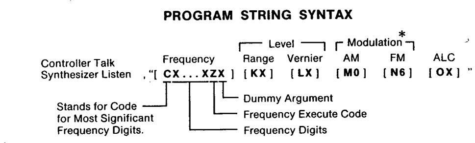

| PROGRAM CODES | ARGUME | ITS | ||
|---|---|---|---|---|
| FREQUENCY |
10 GHz
1 GHz 100 MHz 10 MHz 1 MHz 100 kHz 10 kHz 1 kHz EXECUTE |
@ or P
A or Q B or R C or S D or T E or U F or V G or W J or Z |
0 THROU | GH 9 |
| OUTPUT LEVEL RANGE | K or j | - |
0 dB
-10 -20 -30 -40 -50 -60 -70 -80 -90 -100 -110 |
0
1 2 3 4 5 6 7 8 9 :; |
| PROGRAM | N CODES | ARGUME | NTS | ||
|---|---|---|---|---|---|
| OUTPUT LEVEL VERNIER | L or \ |
+3 dBm
+2 +1 0 -1 -2 -3 -4 -5 -6 -7 -8 -9 -10 |
0
1 2 3 4 5 6 7 8 9 :;<= |
||
| AM | Mc | or ] * | OFF | 0 | or 1 |
| M H | No | r ~ * | OFF | 6 | or 7 |
| A | RGUMENTS | ||||
|
PRUGRAM
CODES |
Δ١ ( | 2 | R | F | |
| U. | - | OFF | 0N | ||
| AL | 0 or |
INT NORI
INT, +10 I XTAL, NC XTAL, +10 MTR, NOI MTR, +10 |
MAL
RANGE DRMAL D RANGE RMAL RANGE |
0
2 4 6 < > |
1
3 5 7 = ? |
STATUS BYTE
| Bit Number | 8 | 7 | 6 | 5 | 4 | 3 | 2 | 1 |
|---|---|---|---|---|---|---|---|---|
| Decimal Value | 128 | 64 | 32 | 16 | 8 | 4 | 2 | 1 |
| Function |
CRYSTAL
OVEN COLD |
REQUEST
SERVICE |
OUT OF
RANGE (Frequency) |
RF
OFF |
NOT
PHASE LOCKED |
LEV
UNCAL |
0
(NOT USED) |
+10 dBm
OVER RANGE |

*Dummy codes for 8672A program compatibility.
Operation
OPERATOR'S CHECKS
3-38. OPERATOR'S CHECKS
3-39. Basic Functional Checks
Description The purpose of these checks is to give reasonable assurance that the instrument is operating properly.
Each check has been designed to be performed with a minimum of test equipment, and in as short a time as possible. Therefore, although these checks are extremely valuable in identifying malfunctions, they are not a substitute for the Performance Tests in Section IV, which verify that the instrument is performing within its published specifications.
Each check is independent of the others and can be performed separately.
If a malfunction is suspected and the CW Generator is being returned to Hewlett-Packard for service, perform the entire procedure. Document the checks that failed on a blue repair tag located at the rear of this manual and attach the tag to the instrument. This will help ensure that the malfunction has been accurately described to service technicians for the best possible service.
Equipment Attenuator, 10 dB ..... HP 8491B. Option 010
Procedure Turn-On Check
- 1. Set the LINE switch to STANDBY. Remove all external cables from the front and rear panels of the CW Generator, including the power cable connecting the instrument to mains power.
- 2. Set the rear panel FREQ STANDARD INT/EXT switch to INT and connect the JUMPER (A3W3) between A3J9 and A3J10.
- 3. After the power cable has been disconnected from the CW Generator for at least 1 minute, reconnect it to the CW Generator. Check the front panel of the instrument to verify that the STANDBY and OVEN status annunciators are on.
- 4. Leave the instrument's LINE switch set to STANDBY until the OVEN status annunciator turns off. This should occur in 15 minutes or less, depending upon how long the CW Generator was disconnected from mains power. (The OVEN annunciator may flicker off and on temporarily just as the oven stabilization temperature is reached. This is normal operation.) Once the OVEN status annunciator is off set the LINE switch to ON.
- 5. Set the RF OUTPUT switch to ON. Set the FREQ STANDARD INT/EXT switch to EXT. Verify that the INTERNAL REF OFF and NOT PHASE LOCKED status annunciators turn on. Set the switch back to INT. The status annunciators shold then turn off.
Frequency Check
The FREQUENCY MHz display and NOT PHASE LOCKED status annunciator are used to check that the internal phase-lock loops remain phase locked across their tuning range. The actual frequency at the RF OUTPUT connector is not
HP 86~1B
OPERATOR'S CHECKS
Procedure (cont'd) checked. However, the frequency can be monitored with a microwave frequency counter or spectrum analyzer for greater assurance that the CW Generator is operating properly.
If a frequency counter is to be used to check frequency, disconnect the jumper from the rear panel connector A3J10 and connect the frequency counter as shown in Figure 3-7. Set the CW Generator rear panel INT-EXT switch to EXT.
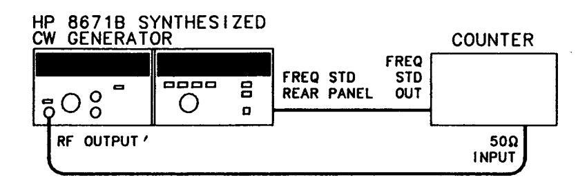

6. Set the CW Generator as follows:
| RF OUTPUT | OFF |
|---|---|
| PEAK-NORM control | NORM (in detent) |
| OUTPUT LEVEL RANGE selector | fully counter-clockwise |
| OUTPUT LEVEL VERNIER | fully counter-clockwise |
| ALC selector | INT |
| ALC CAL control | fully clockwise |
7. Press the HOLD key. Verify that the CW Generator's displays indicate the following conditions:
| RANC | E dB display | -110 dB |
|---|---|---|
| Meter | <-10 dBm | |
| ALC a | nnunciator | INT and LVL UNCAL |
| RF an | nunciator | OFF |
| FREQ | UENCY MHz display |
some frequency between 2.0 and
18.599997 GHz. If the display is not stable, press the PRESET (3 GHz) key. |
| FREQ | UENCY RESOLUTION display | All four segments extinguished. |
| STATUS | S annunciators: | |
| OVEN | 1 |
may be on but should extinguish
within 15 minutes after line cord is connected. |
| NOT | ON |
NOT PHASE LOCKED annunciator C
All other annunciators should be extinguished.
Operation
| OPERATOR'S CHEC | KS | ||||
|---|---|---|---|---|---|
|
Procedure
(cont'd) |
8. Press the PRESET (3 GHz) key and then the 100 MHz FREQUENCY RESO-
LUTION key. Verify that the leftmost segment in the FREQUENCY RESOLU- TION display lights and that the other segments are extinguished. |
||||
|
NO
Do not tune above 6199.999 |
TE
MHz in steps 9 through 17. |
||||
|
n be tuned in 100 MHz increments using | ||||
|
10. Press the 1 MHz FREQUENCY RESO
segments in the FREQUENCY RESO that the other segments are extinguishe |
LUTION key. Verify that the two leftmost
LUTION display are lighted and ed. |
||||
| 11. Verify that the displayed frequency can TUNING knob. | 11. Verify that the displayed frequency can be tuned in 1 MHz increments using the TUNING knob. | ||||
|
12. Press the 10 kHz FREQUENCY RESOLUTION key. Verify that the three left-
most segments in the FREQUENCY RESOLUTION display are lighted and that the other segment is extinguished |
|||||
| 13. Verify that the displayed frequency can be tuned in 10 kHz increments using the TUNING knob. | |||||
| 14. Press the 1 kHz FREQUENCY RESOLUTION key. Verify that all segments in the FREQUENCY RESOLUTION display are lighted. | |||||
|
15. Verify that the displayed frequency can
TUNING knob. |
n be tuned in 1 kHz increments using the | ||||
|
16. Tune the frequency to 4 GHz and pre
segments of the FREQUENCY RESOLU |
ess the HOLD key. Verify that the four
JTION display are extinguished. |
||||
| 17. Press the PRESET (3 GHz) key and verify that the FREQUENCY RESOLUTION display indicates 3000.000 MHz. | |||||
| 18. Set the CW Generator as follows: | |||||
| RF OUTPUT | ON | ||||
| PEAK-NORM control | NORM (in detent) | ||||
| OUTPUT LEVEL RANGE selector | 0 dB range | ||||
| - | OUTPUT LEVEL VERNIER | for 0 dBm reading on meter | |||
| ALC selector | INT | ||||
| ALC CAL control | fully clockwise | ||||
|
19. Tune the CW Generator frequency to
RESOLUTION. Slowly tune from 2000 the NOT PHASE LOCKED annunciator |
2 GHz and select 1 kHz FREQUENCY
.000 MHz to 2000.010 MHz. Verify that remains off at each step. |
||||
|
20. Set the frequency tuning resolution to t
For each tuning resolution, slowly tune to the stop frequency. Each time, verify ciator remains off. (Each phase-locked lo |
the values shown in the following table.
from the corresponding start frequency that the NOT PHASE LOCKED annun- op is tuned over its entire range.) |
||||

| Procedure |
|---|
| (cont'd) |
| FREQUENCY RESOLUTION | Start Frequency | Stop Frequency |
|---|---|---|
| 10 kHz | 2000.010 MHz | 2001.000 MHz |
| 1 MHz | 2001.000 MHz | 2100.000 MHz |
| 100 MHz | 2100.000 MHz | 6200.000 MHz |
21. Set the frequency to 18599.997 MHz (overrange). Verify that the NOT PHASE LOCKED annunciator remains off.
Output Level Check
The CW Generator's internal output leveling loop (ALC) is checked to ensure that it remains locked at all specified power levels. The internal output leveling loop monitors most of the RF output circuitry. The output level can be monitored with a power meter for greater assurance that the CW Generator is operating properly.
22. Press PRESET (3 GHz). Set the CW Generator as follows:
| · | |
|---|---|
| RF OUTPUT | ON |
| PEAK-NORM control | NORM (in detent) |
| OUTPUT LEVEL RANGE selector | fully counter-clockwise |
| OUTPUT LEVEL VERNIER | fully counter-clockwise |
| ALC selector | INT |
| ALC CAL control | fully clockwise |
- 23. Connect a 50 ohm load or attenuator to the CW Generator's RF OUTPUT connector. This reduces unwanted power reflections back into the RF OUTPUT connector, thus avoiding a false LVL UNCAL annunciator indication.
- 24. Tune the frequency to 6200.000 MHz.
- 25. Using the OUTPUT LEVEL RANGE selector, step the output level range from -110 to +10 dB. Verify that the LVL UNCAL annunciator remains off.
- 26. Set OUTPUT LEVEL RANGE to 0 dBm and sweep the OUTPUT LEVEL VERNIER across its entire range. Verify that the annunciator remains off at all VERNIER settings.
- 27. Select 100 MHz frequency tuning resolution and set the output level to +8 dBm. Tune slowly from 2000.000 MHz to 18000.000 MHz. Verify that the indicated power level on the CW Generator's meter remains constant and stable and that the LVL UNCAL annunciator remains off. This ensures that the instrument can generate specified output power and remain leveled.
NOTE
Momentary flashing of the LVL UNCAL when tuning is normal. Make sure that it remains off after the meter has settled, at each frequency.
3-40. HP-IB Checks
DESCRIPTION: These procedures check the CW Generator's ability to process or send the HP-IB messages described in Table 3-3. Only the CW Generator, a controller, and an HP-IB controller interface (for the HP-85B) are needed to perform these checks.
These procedures do not check that all the CW Generator's program codes are being properly executed by the instrument. However, if the Basic Functional Checks and the HP-IB Checks all pass, then the instrument will probably execute all commands.
If the CW Generator fails any of these HP-IB checks, make sure the controller and interface are working properly.
The select code of the controller's HP-IB interface is assumed to be 7. The address of the CW Generator is assumed to be 19 (its factory-set address). This particular select code-address combination (that is, 719) is not necessary for these checks to be valid. However, the program lines presented here must be modified for any other combination.
Instructions for changing the address are in Section II, Installation.
These checks can be performed together or separately. Any special requirements for a check are described at the beginning of the check.
INITIALThe test setup is the same for all of the HP-IB Checks. Connect the the CW GeneratorSETUP:to the controller and set the CW Generator as follows:
| RF Output switch | ON |
|---|---|
| PEAK-NORM control | NORM (in detent) |
| OUTPUT LEVEL RANGE selector | fully counter-clockwise |
| OUTPUT LEVEL VERNIER | fully clockwise |
| ALC selector | INT |
| CAL control | fully clockwise |
| Frequency | 6000.000 MHz |
EQUIPMENT: HP-IB Controller/Interface ....................................
HP 9826A Option 011 (BASIC 2.0 ROM Operating System) - or -HP 9836A with BASIC 2.0 Operating System
Remote and Local Message
NOTE:
This check determines whether the CW Generator properly switches from local to remote control and from remote to local control. If the instrument is in remote, switch the LINE switch to STANDBY, then to ON.
— or —
ي.
HP-IB Checks (cont'd)
| Description | HP-85B (BASIC) |
HP 9826A (BASIC)
HP 9836A (BASIC) |
|---|---|---|
|
Send the Remote message (by setting
the Remote Enable bus control line, REN, true and addressing the CW Generator to listen). |
REMOTE 719 | REMOTE 719 |
OPERATOR'S Check that the CW Generator's REMOTE annunciator is on and the OUTPUT LEVEL meter reads -10 dBm.
| Send the Local message to the CW Generator. | LOCAL 719 | LOCAL 719 |
|---|---|---|
| Off Constation: |
OPERATOR'S Check that the CW Generator's REMOTE annunciator is off and the OUTPUT LEVEL meter reads +3 dBm.
Receiving the Data Message
NOTE:
This check determines whether the CW Generator properly receives Data messages.
| Description | HP-85B (BASIC) |
HP 9826A (BASIC)
HP 9836A (BASIC) |
|---|---|---|
|
Send the first part of the Remote
message (enabling the CW Generator to remote.) |
REMOTE 7 | REMOTE 7 |
|
Address the CW Generator to listen
(completing the Remote message), then send a Data message. |
OUTPUT 719;
"P18W0Z173075" |
OUTPUT 719;
"P18W0Z173075" |
OPERATOR'S RESPONSE: Check that the CW Generator's REMOTE annunciator is on, RANGE dB indicates -70 dB, ALC annunciators show XTAL mode and LVL UNCAL, and the FRE-QUENCY MHz display shows 18000 MHz.
Sending the Data Message
NOTE:
This check determines whether the CW Generator properly issues a Data message when addressed to talk. Before beginning this test, set the LINE switch to OFF, then to ON. (If an HP 9826A or 9836A controller is used, a short program is required to perform this check.)
Operation
OPERATOR'S CHECKS
HP-IB Checks (cont'd)
| Description | HP-85B (BASIC) |
HP 9826A (BASIC)
HP 9836A (BASIC) |
|---|---|---|
| Send the Remote message. | REMOTE 719 | 10 REMOTE 719 |
| Send a Data message to set the status byte. |
OUTPUT 719;
"M070" |
20 OUTPUT 719;
"M070" |
| Address the CW Generator to talk and store its output in variable V. |
ENTER 719
using "#,B";V |
30 V=0
40 ENTER 719 using "# B"·V |
| Display the value of V. | DISP V |
50 DISP V
60 END |
OPERATOR'S Check that the CW Generator's REMOTE annunciator is on. The controller should display 28.
Receiving the Clear Message
NOTE:
This check determines whether the CW Generator responds properly to the Clear message. This Check assumes that the CW Generator is in remote mode.
| Description | HP-85B (BASIC) |
HP 9826A (BASIC)
HP 9836A (BASIC) |
|---|---|---|
| Send a Data message to initialize the CW Generator |
Output 719;
"P18W0Z173075" |
Output 719;
"P18W0Z173075" |
OPERATOR'S RESPONSE: Check that the CW Generator is set to 18000 MHz, XTAL ALC mode, and RF OUTPUT ON.
| Send the Clear message | CLEAR 719 | CLEAR 719 |
OPERATOR'S Check that the CW Generator is set to 3000 MHz, INT ALC mode, and RF OUTPUT OFF.
Receiving the Abort Message
NOTE: This check determines whether the CW Generator becomes unaddressed when it receives the Abort message. This check assumes the CW Generator is in remote mode and at a frequency other than 2000 MHz.
HP-IB Checks (cont'd)
| Description | HP-85B (BASIC) |
HP 9826A (BASIC)
HP 9836A (BASIC) |
|---|---|---|
|
Address the CW Generator to listen
and send part of a frequency message. |
OUTPUT 719;
"A2000" |
OUTPUT 719;
"A2000" |
| Send the Abort message, unaddressing the CW Generator from listening. | ABORTIO 7 | ABORT 7 |
| Address the controller to talk. The CW Generator is not addressed to listen. | SEND 7; MTA | SEND 7; MTA |
|
Attempt to execute the previous
frequency command by sending the frequency execute command. |
OUTPUT 7; "Z1" | OUTPUT 7; "Z1" |
OPERATOR'S Check that the CW Generator does not display 2000 MHz output frequency. If the controller is an HP 9826A or 9836A, press the CLR I/O key to continue the checks.
Status Byte Message
NOTE:
This check determines whether the CW Generator sends the Status Byte message. This check assumes that the Clear message has been sent.
| Description | HP-85B (BASIC) |
HP 9826A (BASIC)
HP 9836A (BASIC) |
|---|---|---|
|
Send the Serial Poll message to the
CW Generator (causing it to send the Status Byte message). Display the value of the status byte. |
SPOLL(719) | SPOLL(719) |
OPERATOR'S Check that the controller's display reads 28.
RESPONSE :
Require Service Message
NOTE:
This check determines whether the CW Generator can issue the Require Service message (set the SRQ bus control line true). This check can be performed in either local or remote mode.
| Description | HP-85B (BASIC) |
HP 9826A (BASIC)
HP 9836A (BASIC) |
|---|---|---|
| Send the Clear message |
CLEAR 719
OUTPUT 719 |
CLEAR 719
OUTPUT 719: |
|
out-of-range frequency. This causes the
Require Service message to be sent. |
"P35Z1" | "P35Z1" |
HP-IB Checks (cont'd)
NOTE:
If an HP 9826A or 9836A controller is being used, a short program is required for the next part of this check.
| Description | HP-85B (BASIC) |
HP 9826A (BASIC)
HP 9836A (BASIC) |
|---|---|---|
|
Read the binary status of the con-
troller's HP-IB interface and store the data in variable V. In this step, 7 is the interface's select code, and 2 (HP-85B) and 7 (HP 9826A) are status registers for bus control lines. |
STATUS 7,2;V |
10 V=0
20 STATUS 7,7; V |
|
Display the value of the SRQ bit. In
this step, 5 (HP-85B) and 10 (HP 9826A or HP 9836A) are the SRQ bits for the controller, numbered from 0. |
DISP "SRQ=";
BIT(V,5) |
30 DISP "SRQ
=";BIT(V,10) 40 END |
OPERATOR'S RESPONSE: Check that the SRQ value is 1, indicating that the CW Generator issued the Require Service message.
Status Bit Message
NOTE:
This check determines whether the CW Generator sends the Status Bit message. This check can be performed in either local or remote mode. This check assumes that the Clear message has been sent.
| Description | HP-85B (BASIC) |
HP 9826A (BASIC)
HP 9836A (BASIC) |
|---|---|---|
|
Set up a Service Request condition by
programming an illegal frequency. |
OUTPUT 719;
"P99Z1" |
OUTPUT 719;
"P99Z1" |
| CW Generator (causing it to send the Status Bit message). | PPOLL(7) | PPOLL(7) |
OPERATOR'S (RESPONSE:
Check that the controller displays 128, or the value of the bit that parallel poll switch is set to.
SECTION IV PERFORMANCE TESTS
4-1. INTRODUCTION
The procedures in this section test the instrument's electrical performance using the specifications of Table 1-1 as the performance standards. These tests are suitable for incoming inspection, troubleshooting, and preventive maintenance. All tests can be performed without accessing the interior of the instrument. A simpler operational test is included in Section III under Operator's Checks.
4-2. ABBREVIATED PERFORMANCE TEST
In most cases, it is not necessary to perform all of the tests in this section. The following tests should be performed after repairing the CW Generator or to verify instrument operation:
FREQUENCY RANGE AND RESOLUTION, OUTPUT LEVEL, HIGH LEVEL ACCURACY AND FLATNESS
These tests can also be used for incoming inspections and preventative maintenance. They are not intended to be a complete check of specifications, but will provide 90% confidence that the CW Generator is meeting its major performance specifications. These tests can be performed with less time and equipment than the full Performance Tests
NOTE
To consider the performance tests valid, the following conditions must be met:
a. The CW Generator must have a 1hour warmup for all specifications.
b. The line voltage must be 100, 120, 220, or 240 Vac +5%, -10%.
c. The ambient temperature must be +15 to +35°C for the Output Level Flatness and RF Output Level and Accuracy tests; 0 to 55°C for all other tests.
4-3. CALIBRATION CYCLE
This instrument requires periodic verification of performance to ensure that it is operating within
specified tolerances. The performance tests described in this section should be performed at least once each year; under conditions of heavy usage or severe operating environments, the tests should be more frequent. Adjustments that may be reguired are described in Section V. Adjustments.
4-4. PERFORMANCE TEST RECORD
Results of the performance tests may be tabulated in Table 4-3, Performance Test Record. The Performance Test Record lists all of the performance test specifications and the acceptable limits for each specification. If performance test results are recorded during an incoming inspection of the instrument, they can be used for comparison during periodic maintenance or troubleshooting. The test results may also prove useful in verifying proper adjustments after repairs are made.
4-5. EQUIPMENT REQUIRED
Equipment required for the performance tests is listed in Table 1-3, Recommended Test Equipment. Any equipment that satisfies the critical specifications given in the table may be substituted.
4-6. TEST PROCEDURES
It is assumed that the person performing the following tests understands how to operate the specified test equipment. Equipment settings, other than those for the CW Generator, are stated in general terms. For example, a test might require that a spectrum analyzer's resolution bandwidth be set to 100 Hz; however, the sweep time would not be specified and the operator would be expected to set that control and other controls as required to obtain an optimum display. It is also assumed that the technician will select the cables, adapters, and probes (listed in Table 1-3) required to complete the test setups illustrated in this section.
4-7. FREQUENCY RANGE AND RESOLUTION TEST
Specification
| Electrical Characteristics | Performance Limits | Conditions |
|---|---|---|
| FREQUENCY | ||
| Range |
2.0—18.0 GHz
(Overrange in 18.599997 GHz) |
|
| Resolution |
1 kHz
2 kHz 3 kHz |
2.0 to 6.2 GHz
6.2 to 12.4 GHz 12.4 to 18.0 GHz |
Description This test checks the resolution in each of three internal frequency bands using a frequency counter. The performance test is divided into a baseband check (2.0 to 6.2 GHz) and a check for bands 2 and 3 (6.2 to 12.4 GHz and 12.4 to 18.0 GHz respectively).
Equipment Frequency Counter ....................................
Procedure Baseband Test
1. Connect the equipment as shown in Figure 4-1. Set the CW Generator rear panel INT/EXT switch to EXT. Remove FREQ STANDARD jumper and connect A3J10 to the 10 MHz frequency standard output of the frequency counter.

Figure 4-1. Frequency Range and Resolution Test Setup
- 2. Select 1 kHz display resolution on the counter.
- 3. Press the CW Generator's PRESET (3 GHz) key and set the output power to 0 dBm.
- 4. Verify that the frequency counter reads 3 000.000 MHz ±1 count.
2 999.999 MHz _____ 3 000.001 MHz
- 5. Set the CW Generator frequency to 2 000.000 MHz.
- 6. Tune to each of the frequencies listed below. Verify that the CW Generator remains phase locked at all frequencies and that the frequency counter agrees with the CW Generator frequency display ±1 count.
4-2
FREQUENCY RANGE AND RESOLUTION (cont'd)
Procedure (cont'd)
|
Frequency
(MHz) |
Minimum Frequency
(MHz) |
Actual Frequency
(MHz) |
Maximum Frequency
(MHz) |
|---|---|---|---|
| 2 000.000 | 1 999.999 | 2 000.001 | |
| 2 000.001 | 2 000.000 | 2 000.002 | |
| 2 001.112 | 2 001.111 | 2 001.113 | |
| 2 002.223 | 2 002.222 | 2 002.224 | |
| 2 003.334 | 2 003.333 | 2 003.335 | |
| 2 004.445 | 2 004.444 | 2 004.446 | |
| 2 005.556 | 2 005.555 | 2 005.557 | |
| 2 006.667 | 2 006.666 | 2 006.668 | |
| 2 007.778 | 2 007.777 | 2 007.779 | |
| 2 008.889 | 2 008.888 | 2 008.890 | |
| 2 009.999 | 2 009.998 | 2 010.000 |
7. Set the CW Generator to 2 000.000 MHz.
8. Tune the CW Generator to each of the frequencies listed below and read the frequency counter at each step. The frequency counter reading should agree with the CW Generator front panel reading within ±1 count. In addition, the CW Generator NOT PHASE LOCKED front panel annunciator should remain off at all frequencies.
NOTE
Fast tuning of frequency may cause the NOT PHASE LOCKED annunciator to flash on momentarily. This is normal and does not indicate a malfunction.
|
Frequency
(MHz) |
Minimum Frequency
(MHz) |
Actual Frequency
(MHz) |
Maximum Frequency
(MHz) |
|---|---|---|---|
| 2 090.000 | 2 089.999 | 2 090.001 | |
| 2 280.000 | 2 279.999 | 2 280.001 | |
| 2 470.000 | 2 469.999 | 2 470.001 | |
| 2 660.000 | 2 659.999 | 2 660.001 | |
| 2 850.000 | 2 849.999 | 2 850.001 | |
| 3 040.000 | 3 039.999 | 3 040.001 | |
| 3 230.000 | 3 229.999 | 3 230.001 | |
| 3 420.000 | 3 419.999 | 3 420.001 |
(cont'd)
FREQUENCY RANGE AND RESOLUTION (cont'd)
Procedure (cont'd)
|
Frequency
(MHz) |
Minimum Frequency
(MHz) |
Actual Frequency
(MHz) |
Maximum Frequency
(MHz) |
|
|---|---|---|---|---|
| 3 610.000 | 3 609.999 | 3 610.001 | _ | |
| 3 800.000 | 3 799.999 | 3 800.001 | ||
| 3 990.000 | 3 989.999 | 3 990.001 | ||
| 4 180.000 | 4 179.999 | 4 180.001 | ||
| 4 370.000 | 4 369.999 | 4 370.001 | ||
| 4 560.000 | 4 559.999 | 4 560.001 | ||
| 4 750.000 | 4 749.999 | 4 750 001 | ||
| 4 940.000 | 4 939.999 | 4 940 001 | ||
| 5 130.000 | 5 129.999 | 5 130 001 | ||
| 5 320.000 | 5 319.999 | 5 320 001 | ||
| 5 510.000 | 5 509.999 | 5 510 001 | ||
| 5 700.000 | 5 699.999 | 5 700 001 | ||
| 5 900.000 | 5 899.999 | 5 900 001 | ||
| 6 100.000 | 6 099.999 | 6 100.001 |
Bands 2 and 3 Test
9. Tune the CW Generator to 10 000.000 MHz and select 1 kHz tuning resolution.
- 10. Tune the frequency down one increment and verify that the CW Generator frequency display changes to 9 999.998 MHz and the frequency counter reading agrees within one count.
- 11. Tune the frequency up two increments and verify that the CW Generator frequency display changes to 10 000.002 MHz. Verify also that the frequency counter reading agrees within one count.
10 GHz frequency resolution, 2 kHz _____ (\/)
- 12. Tune the CW Generator to 18 000.000 MHz and select 1 kHz tuning resolution.
- 13. Tune the frequency down one increment and verify that the CW Generator frequency display indicates 17 999.997 MHz and the frequency counter reading agrees within one count.
- 14. Tune the frequency up two increments and verify that the CW Generator frequency display indicates 18 000.003 MHz and the frequency counter reading agrees within one count.
18 GHz frequency resolution, 3 kHz _____ (\sqrt{)}
15. Disconnect the frequency standard cable and replace the FREQ STANDARD JUMPER between A3J9 and A3J10. Set the INT/EXT switch to INT.
4-8. FREQUENCY SWITCHING TIME TEST
Specification
| Electrical Characteristics | Performance Limits | Conditions |
|---|---|---|
| SWITCHING TIME | ||
| Frequency to be within the specified resolution. | <15 ms | |
|
Amplitude to be within ±3 dB
of final level after switching frequency. |
<15 ms |
When switching within
the same frequency resolution range. |
Description This test measures the frequency switching speed. The CW Generator is remotely programmed to continuously switch between two frequencies. Its output is mixed with a local oscillator whose output frequency is set to 1 kHz above the second (or destination) frequency. The difference frequency (IF) is displayed on an oscilloscope.
Frequency switching speed is first measured in the CW Generator's base band (2.0— 6.2 GHz) using an IF frequency of 1 kHz (which is the specified resolution for the base band). As the unit under test is switched from the starting frequency to the destination frequency the oscilloscope is triggered by the HP-IB controller.
As the CW Generator output changes between the two programmed frequencies the IF signal will pass through zero. This will generate a phase reversal, as shown in Figure 4-3. The last phase change of the IF frequency is the point that the frequency of the unit under test is within the specified resolution.
The amplitude recovery time is tested using the same measurement setup. The ±3 dB amplitude points of the IF signal are calibrated on the oscilloscope display and the amplitude recovery time is tested to ensure that the IF level is within ±3 dB of the final level (see Figure 4-4). The amplitude recovery time is only specified for frequency changes within the same frequency resolution range.
NOTE
A digitizing oscilloscope will make this measurement easier due to the ability to store and view the switching process. The test may be performed without a digitizing oscilloscope by repetitively switching the frequency of the unit under test.
| Equipment | HP-IB Controller | HP | 85B/82903 | or | HP | 9836A |
|---|---|---|---|---|---|---|
| Local Oscillator | HP | 8340A | ||||
| Mixer | RHO | G DMS1-18 | ||||
| Oscilloscope | HP | 1980B |

FREQUENCY SWITCHING TIME TEST (cont'd)
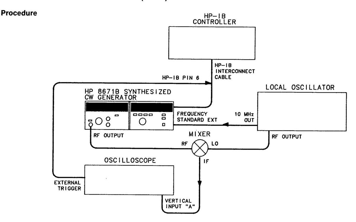
Figure 4-2. Frequency Switching Time Test Setup
Frequency Switching Time
1. Set up the equipment as shown in Figure 4-2. The external trigger input of the oscilloscope should be connected to pin 6 of the HP-IB cable. An HP-IB adapter (HP 10834A) can be used to make a permanent adapter for this test. This test may be performed by connecting the external trigger input of the oscilloscope to A2A7TP1. The test results should be identical for both methods of oscilloscope triggering.

To access A2A7TP1 the instruments protective covers must be removed. This should only be done by service-trained personnel who are aware of the hazards involved (for example, fire and electrical shock).
- 2. Set the local oscillator to 2 100.001 MHz with an output level between +5 dBm and +8 dBm.
- 3. Set the oscilloscope to external trigger, positive slope trigger, triggered sweep mode (or NORMAL) and 2 ms per division sweep time.
FREQUENCY SWITCHING TIME TEST (cont'd)
Procedure (cont'd)
NOTE
The following programs are for the HP 9826 or HP 9836 controller. For use with the HP 85B controller, increase the wait statements by a factor of 1000. This is done because the HP 85B executes wait commands in milliseconds while the HP 9836 and HP 9826 execute wait commands in seconds.
-
4. Load and run the following HP-IB controller program. As the program is executing, adjust the trigger controls for a stable 1 kHz sine wave display.
- 10 CLEAR 719 20 OUTPUT 719; "A2100000Z100075" 30 GOTO 20
- 5. Press the pause key on the controller to stop the program. Load and run the following program. The program will continue switching the CW Generator between 18 GHz and 2.1 GHz until the pause key is pressed. If necessary, adjust the oscilloscope triggering to obtain a display similar to that shown in Figure 4-3.
| Controller talk, CW Generator lister | ||
|---|---|---|
| 10 | SEND 7; MTA LISTEN 19 | 0 dB range, Ext ALC |
| 20 | OUTPUT 7; "K00075" | Set to 18 GHz |
| 30 | OUTPUT 7: "P18000000Z1" | |
| ······ | 5 for HP 85B (5 ms) | |
| 40 | WAIT .005 | Ready for change to 2.1 GHz |
| 50 | OUTPUT 7; "A210000Z" | |
| 60 | WAIT .7 | - 700 for HP 85B (700 ms) |
| 70 | OUTPUT 7;" 1 " | |
| 80 | WAIT .05 | - 50 for HP 85B (50 ms) |
| 90 | GOTO 30 | |
| 100 | END | |
FREQUENCY SWITCHING TIME TEST (cont'd)

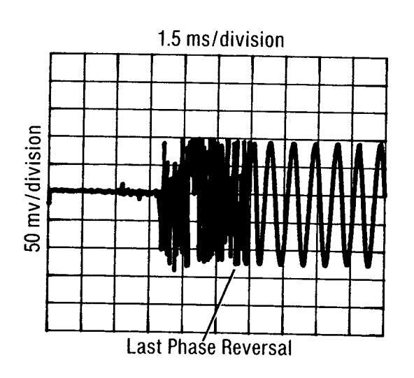
Figure 4-3. Frequency Switching Time Measurement Waveform
6. Measure the switching time by observing the signal on the oscilloscope display. The external trigger is the reference for determining switching speed. The switching time is measured from the display's left graticule to the last phase reversal (as the CW Generator passes the local oscillator frequency) before the IF signal settles into a steady frequency. Refer to Figure 4-3. Record the frequency switching time.
_____<15 ms
- Frequency 2.1 GHz
7. Modify lines 30 and 50 to read as follows:
30 OUTPUT 7; "A2100000Z1"
50 OUTPUT 7; "P18000000Z"
- 8. Set the local oscillator frequency to 17 999.997 MHz.
- 9. Run the modified program and measure the switching time to the last phase reversal
_____<15 ms
Amplitude Recovery Time
10. Set the local oscillator to 6 100.001 MHz.
11. Load and run the following program. Adjust the vertical sensitivity and position of the display until the displayed signal indicates a peak-to-peak change of exactly 2 divisions in amplitude. This calibrates the oscilloscope to ±3 dB about 0 dBm. The smaller signal represents -3 dBm and the larger signal represents +3 dBm.
4-8
FREQUENCY SWITCHING TIME TEST (cont'd)
|
Procedure
(cont'd) |
10
20 |
CLEAR 719
OUTPUT 719; "A6100000Z1" |
- Frequency 6.1 GHz |
|---|---|---|---|
| 30 | FOR X=1 TO 100 | ||
| 40 | OUTPUT 719; "K00071" | - Level +3 abili | |
| 50 | NEXT X | ||
| 60 | FOR Y=1 TO 100 | ||
| 70 | OUTPUT 719; "K06071" | - Level -3 dBm | |
| 80 | NEXT Y | ||
| 90 | GOTO 30 | ||
| 100 | END | · |
- 12. Set the top of the displayed signal to a convenient reference near the center of the display. Note the two levels for reference. The measurement will be determined by the time required before the amplitude of the IF signal stays between these two levels.
- 13. Press the pause key on the controller. Enter and run the following program. Run the program by typing RUN 110 and pressing the EXECUTE key (END LINE for the HP 85).
| - 2.0 GHz, 0 dBm, internal ALC | ||
|---|---|---|
| 110 | OUTPUT 719; "A2000000Z103071" | |
| - Controller talk, CW generator listen | ||
| 120 | SEND 7; MTA LISTEN 19 | |
| - Frequency 2.1 GHz | ||
| 130 | OUTPUT 7; "A2100000Z1" | |
| - 5 for HP 85B (5 ms) | ||
| 140 | WAIT ,005 | |
| - Frequency 6.1 GHz | ||
| 150 | OUTPUT 7;"A6100000Z" | |
| 160 | 700 (ar LID (ED (700 ma) | |
| 4 17 0 | - 700 for HP 85B (700 his) | |
| 170 |
UUIPUI /;"1"
T |
|
| 180 | ||
| 100 | COTO 1 20 | = 50 for HP 85B (50 ms) |
| 170 | COLO ION | |
| 200 | FND | |
| V U |
tus t v
|
FREQUENCY SWITCHING TIME TEST (cont'd)
Procedure (cont'd)
14. Measure the amplitude recovery time. The measurement is the time from the left graticule of the display to the last time the IF signal amplitude is outside of the reference points noted in step 13. If necessary, adjust the oscilloscope triggering to obtain a display similar to that shown in Figure 4-4
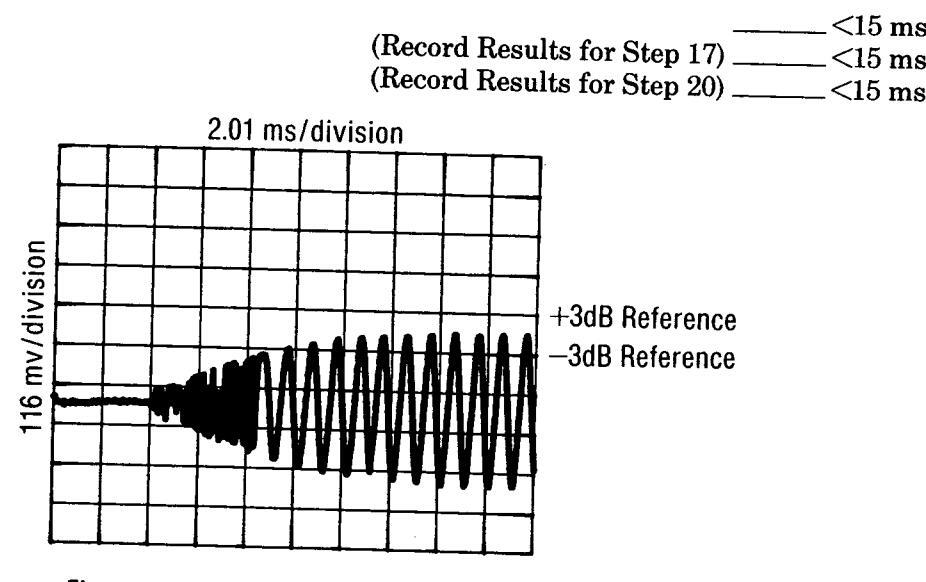
Figure 4-4. Amplitude Recovery Measurement Waveform
15. Set the local oscillator to 12 300.002 MHz
16. Modify lines 20, 130, and 150 of the program as follows:
20 OUTPUT 719: "P1230000071" Frequency 12.3 GHz
130 OUTPUT 7; "A6200000Z1 "
150 OUTPUT 7; "P1230000071"
- 17. Repeat steps 11 through 14 using the modified programs. The amplitude recovery time will be measured for the 2 kHz resolution band.
- 18. Set the local oscillator to 18.000 003 GHz.
- 19. Modify lines 20, 130, and 150 of the program as follows:
| 20 | OUTPUT | 719; "P18000000Z1 " |
|---|---|---|
| 130 | OUTPUT | 7; "P12400000Z1 " Frequency 12.4 GHz |
| 150 | OUTPUT | 7; "P1800000Z" Frequency 18.0 GHz |
- 20. Repeat steps 11 through 14 using the modified program. The amplitude recovery time will be measured for the 3 kHz resolution band.
- 21. Disconnect the frequency reference from the rear panel and replace the jumper. Set the switch to INT.
4-10

4-9. OUTPUT LEVEL, HIGH LEVEL ACCURACY AND FLATNESS TEST
Specification
| Electrical Characteristics | Performance Limits | Conditions |
|---|---|---|
| RF OUTPUT | ||
| Output Level: | ||
| Leveled Output | +8 dBm to120 dBm | +15 to +35°C |
| Remote Programming | 2.0—6.2 GHz | |
| Absolute Level | ±1.00 dB | +10 dB output level range |
| Accuracy (+15°C to | ±1.00 dB | 0 dB output level range |
| +35°C) | ±1.50 dB | –10 dB output level range |
| , | ±1.70 dB | -20 dB output level range |
| 6.2—12.4 GHz | ||
| +1.25 dB | +10 dB output level range | |
| +1.25 dB | 0 dB output level range | |
| ±1.75 dB | -10 dB output level range | |
| ±1.95 dB | -20 dB output level range | |
| 12 4—18.0 GHz | ||
| +1 50 dB | +10 dB output level range | |
| +1.50 dB | 0 dB output level range | |
| ±2.10 dB | -10 dB output level range | |
| ±2.30 dB | -20 dB output level range | |
| Manual Absolute | Add +0.75 dB to remote | Absolute level accuracy |
| Level Accuracy | programming absolute | specifications include |
| level accuracy | allowances for detector | |
| linearity, temperature, | ||
| flatness, attenuator accu | ||
| racy, and measurement | ||
| uncertainty. | ||
| Flatness | 1.50 dB | 2.0 to 6.2 GHz |
| (0 dBm range; 15 to | 2.00 dB | 2.0 to 12.4 GHz |
| +35°C) | 2.50 dB | 2.0 to 18.0 GHz |
Description This test checks output level (maximum leveled power), absolute level accuracy between +8 dBm and -20 dBm, and output level flatness. The output level test uses a power meter to verify that +8 dBm can be generated over the full 2 to 18 GHz frequency range. Level flatness measures the variation in level over the various specified ranges. The high level accuracy test verifies that power levels between +8 dBm and -20 dBm are within the manual absolute level accuracy specification.
Equipment Power Meter ...................................
Procedure Output Level Test
1. Connect the power sensor to the power meter. Calibrate and zero the power meter.
2. Connect the power sensor to the RF OUTPUT connector of the CW Generator as shown in Figure 4-5.

OUTPUT LEVEL, HIGH LEVEL ACCURACY AND FLATNESS TEST (cont'd)
Procedure (cont'd)
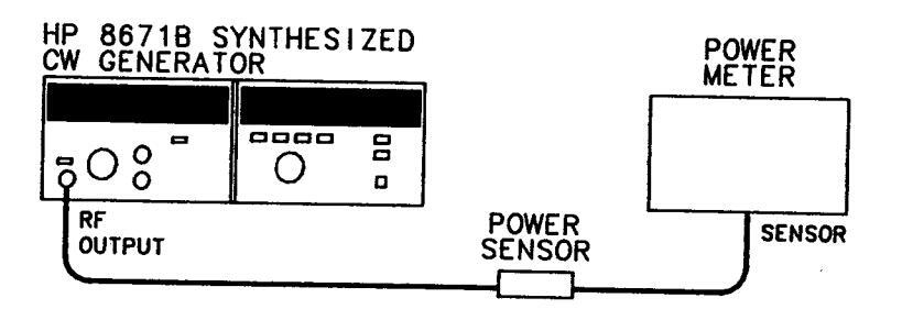
Figure 4-5. Output Level, High Level Accuracy and Flatness Test Setup
- 3. Set the CW Generator frequency to 2.0 GHz and the output level range to +10 dB
- 4. Adjust the VERNIER control to give a power meter reading of +8 dBm.
- 5. Tune the CW Generator in 100 MHz steps from 2 to 18 GHz, adjusting the power meter's calibration factor and recording the frequency at which minimum power occurs. Reset VERNIER to read +8 dBm on the power meter at the recorded frequency to ensure that the +8 dBm power level can be met.
| Frequency | ||
|---|---|---|
| Minimum | Power >+8 dBm |
Level Flatness
6. Set the CW Generator frequency to 2 GHz, output level to −5 dBm, and power meter to dB Relative. Slowly tune to 6.2 GHz in 100 MHz steps and record the maximum and minimum relative power outputs. Set the power meter calibration factor appropriate for each frequency. Maximum variation should be within 1.5 dB (highest point to lowest point). Continue to tune to 12.4 GHz. Maximum variation should be within 2 dB. Continue to tune to 18.0 GHz and note level variation. Maximum variation should be less than 2.5 dB.
NOTE
The specification for power output flatness is not referenced to a particular frequency. The specification represents the total power variation over the entire frequency range.
2.0-6.2 GHz
| Minimum | |
|---|---|
| Maximum | |
| Total Variation | 1 <1 50 dB |
2.0—12.4 GHz
| Min | imum |
|---|---|
| Max | imum |
| otal Variation | <2.00 dB |
4-12
OUTPUT LEVEL, HIGH LEVEL ACCURACY AND FLATNESS TEST (cont'd)
Procedure 2.0—18.0 GHz
Minimum _____ Maximum _____ Total Variation _____<2.50 dB
High Level Accuracy Test
- 7. Connect the power sensor to the power meter. Calibrate and zero the power meter in the dBm mode.
- 8. Connect the power sensor to the RF OUTPUT connector of the CW Generator.
- 9. Set the CW Generator frequency to 2.0 GHz and output level to +8 dBm (+10 dB range and -2 dBm front panel meter setting).
- 10. Tune the CW Generator in 2 GHz steps from 2 to 18 GHz. Set the power meter's calibration factor appropriately and record the power output at each frequency in Table 4-1. The power meter readings should be within the limits specified.
- 11. Repeat steps 9 and 10 for an output level of +3 dBm (+10 dB range, -7 dBm VERNIER).
- 12. Set the CW Generator frequency to 2.0 GHz and output level to 0 dBm (0 dB range, 0 dBm VERNIER).
- 13. Tune the CW Generator in 2 GHz steps from 2 to 18 GHz. Set the power meter's calibration factor appropriately and record the power output at each frequency in Table 4-1. The power meter readings should be within the limits specified.
- 14. Repeat steps 12 and 13 for output levels of -5 dBm and -10 dBm (0 dB range).
- 15. Set the CW Generator frequency to 2.0 GHz and output level to -10 dBm (-10 dB range, 0 dBm VERNIER).
- 16. Tune the CW Generator in 2 GHz steps from 2 to 18 GHz. Set the power meter's calibration factor appropriately and record the power output at each frequency in Table 4-1. The power meter readings should be within the limits specified.
- 17. Repeat steps 15 and 16 for an output level of -20 dBm (-20 dB range, 0 dBm vernier).
OUTPUT LEVEL, HIGH LEVEL ACCURACY AND FLATNESS TEST (cont'd)
Table 4-1. Output Level, High Level Accuracy and Flatness Test Record (1 of 2)
| Test | Results | |||||
|---|---|---|---|---|---|---|
| Min. | Actual | Max. | ||||
| High Level Accuracy | ||||||
| +8 dBm (+10 dB range) | 2 GHz | +6 25 dBm | ||||
| 4 GHz | + 6 25 dBm | +9.75 dBi | ||||
| 6 GHz | + 6.25 dBm | +9.75 dBn | ||||
| 8 GHz | + 6.00 dBm | +10.00 dBn | ||||
| 10 GHz | + 6.00 dBm | +10.00 dBr | ||||
| 12 GHz | + 6.00 dBm | +10.00 dBr | ||||
| 14 GHz | + 5.75 dBm | +10.00 dBr | ||||
| 16 GHz | + 5.75 dBm | +10.25 dBr | ||||
| 18 GHz | + 5.75 dBm | +10.25 dBr | ||||
| +3 dBm (+10 dB range) | 2 GHz | + 1.25 dBm | +4.75 dBr | |||
| 4 GHz | + 1.25 dBm | +4.75 dBr | ||||
| 6 GHz | + 1.25 dBm | +4.75 dBr | ||||
| 8 GHz | + 1.00 dBm | +5.00 dBr | ||||
| 10 GHz | + 1.00 dBm | +5.00 dBr | ||||
| 12 GHz | + 1.00 dBm | +5.00 dBr | ||||
| 14 GHz | + 0.75 dBm | +5.25 dBr | ||||
| 16 GHz | + 0.75 dBm | +5.25 dBr | ||||
| 18 GHz | + 0.75 dBm | +5.25 dBr | ||||
| 0 dBm (0 dB range) | 2 GHz | - 1.75 dBm | +1.75 dBr | |||
| 4 GHz | - 1.75 dBm | +1.75 dBr | ||||
| 6 GHz | – 1.75 dBm | +1.75 dBr | ||||
| 8 GHz | - 2.00 dBm | +2.00 dBr | ||||
| 10 GHz | - 2.00 dBm | +2.00 dBr | ||||
| 12 GHz | - 2.00 dBm | +2.00 dBr | ||||
| 14 GHz | – 2.25 dBm | +2.25 dBr | ||||
| 16 GHz | – 2.25 dBm | +2.25 dBr | ||||
| 18 GHz | - 2.25 dBm | +2.25 dBr | ||||
| −5 dBm (0 dB range) | 2 GHz | -6.75 dBm | -3.25 dBr | |||
| 4 GHz | - 6.75 dBm | -3.25 dBr | ||||
| 6 GHz | - 6.75 dBm | | −3.25 dBr | ||||
| 8 GHz | - 7.00 dBm | | −3.00 dBr | ||||
| 10 GHz | - 7.00 dBm | -3.00 dBr | ||||
| - 7.00 dBm | -3.00 dBr | |||||
| 14 GHZ | - 7.25 dBm | -2.75 dBn | ||||
|
10 GHZ
19 CH- |
- 7.25 dBm | -2.75 dBn | ||||
| 10 GHZ | - 7.25 dBm | −2.75 dBn | ||||
| −10 dBm (0 dB range) | 2 GHz | -11.75 dBm | -8.25 dBn | |||
| 4 GHz | -11.75 dBm | -8.25 dBn | ||||
| 6 GHz | -11.75 dBm | -8.25 dBn | ||||
| 8 GHz | -12.00 dBm | _9.00 JD_ | ||||
| j isouthin j | - o.vv apn | |||||
OUTPUT LEVEL, HIGH LEVEL ACCURACY AND FLATNESS TEST (cont'd)
| Test | Results | |||||
|---|---|---|---|---|---|---|
| Min. | Actual | Max. | ||||
| High Level Accuracy (cont'd) | ||||||
| -10 dBm (0 dB range) (cont'd) | 12 GHz | -12.00 dBm | -8.00 dBm | |||
| 14 GHz | -12.25 dBm | -7.75 dBm | ||||
| 16 GHz | -12.25 dBm | -7.75 dBm | ||||
| 18 GHz | -12.25 dBm | -7.75 dBm | ||||
| -10 dBm (-10 dB range) | 2 GHz | -12.25 dBm | -7.75 dBm | |||
| 4 GHz | -12.25 dBm | -7.75 dBm | ||||
| 6 GHz | -12.25 dBm | -7.75 dBm | ||||
| 8 GHz | -12.50 dBm | -7.50 dBm | ||||
| 10 GHz | -12.50 dBm | −7.50 dBm | ||||
| 12 GHz | -12.50 dBm | −7.50 dBm | ||||
| 14 GHz | -12.85 dBm | −7.15 dBm | ||||
| 16 GHz | −12.85 dBm | −7.15 dBm | ||||
| 18 GHz | 12.85 dBm | -7.15 dBm | ||||
| 20 dBm (-20 dB range) | 2 GHz | 22.45 dBm | −17.55 dBm | |||
| -20 dBin (-20 dB range) | 4 GHz | -22.45 dBm | -17.55 dBm | |||
| 6 GHz | -22.45 dBm | −17.55 dBm | ||||
| 8 GHz | −22.70 dBm | −17.30 dBm | ||||
| 10 GHz | −22.70 dBm | -17.30 dBm | ||||
| 12 GHz | −22.70 dBm | −17.30 dBm | ||||
| 14 GHz | -23.05 dBm | -16.95 dBm | ||||
| 16 GHz | -23.05 dBm | | −16.95 dBm | ||||
| 18 GHz | -23.05 dBm | -16.95 dBm | ||||
Table 4-1. Output Level, High Level Accuracy and Flatness Test Record (2 of 2)
PERFORMANCE TESTS
4-10. LOW LEVEL ACCURACY TEST
Specification
| Electrical Characteristics | Performance Limits | Conditions |
|---|---|---|
| RF OUTPUT | ||
|
Remote Programming
Absolute Level Accuracy (+15 to +35°C) |
±1.90 dB
±1.90 dB plus ±0.3 dB per 10 dB step |
2.0—6.2 GHz
—30 dB output level range <—30 dB output level range |
|
±2.15 dB
±2.15 dB plus ±.3 dB per 10 dB step |
6.2—12.4 GHz
—30 dB output level range <—30 dB output level range |
|
|
±2.40
±2.40 dB plus ±0.4 dB per 10 dB step |
12.4—18.0 GHz
—30 dB output level range <—30 dB output level range |
|
|
Manual Absolute
Level Accuracy |
Add ±0.75 dB to remote pro-
gramming absolute level accuracy |
Absolute level accuracy
specifications include allowances for detector line- arity, temperature, flatness, attenuator accuracy and measurement uncertainty. |
| Description | This test checks absolute level accuracy between -30 dBm and -110 dBm. An IF signal is calibrated to the spectrum analyzer by measuring the CW Generator's RF output at -20 dBm. A reference level corresponding to the -20 dBm output is set on the spectrum analyzer and each 10 dB decrease in range is checked for a 10 dB decrease on the spectrum analyzer display. |
|---|---|
| Equipment | Power MeterHP 436APower SensorHP 8481ALocal OscillatorHP 8340AMixerRHG DMS 1—18Spectrum AnalyzerHP 8566B40 dB AmplifierHP 8447F20 dB AttenuatorHP 8491B Option 02020 dB PreamplifierHP 8447A |
| Procedure |
|
|
NOTE
Connect the mixer directly to the local oscilator to avoid any power loss. |
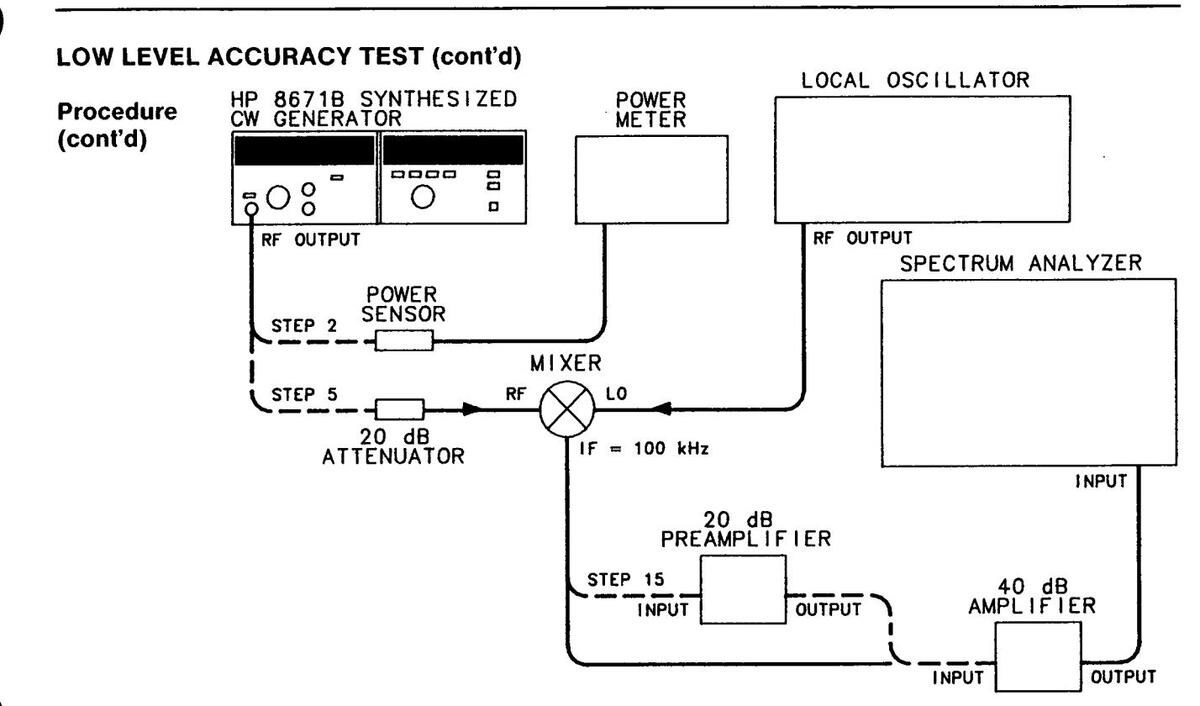
Figure 4-6. Low Level Accuracy Test Setup
- 3. Set the CW Generator frequency to 2 000.000 MHz, RANGE to -20 dB, and set the VERNIER for 0 dBm.
- 4. Adjust the VERNIER for a power meter reading of -20.00 dBm ±0.01 dB.
- 5. Disconnect the power meter and connect the CW Generator to the mixer as shown in Figure 4-6.
- 6. Set the local oscillator to 2 000.100 MHz and output power to maximum but not greater than +8 dBm.
- 7. Set the resolution bandwidth on the spectrum analyzer to 300 Hz or less. Adjust the reference level so that the amplitude of the 100 kHz IF signal is set to a convenient horizontal graticule as a reference. This calibrates the graticule line for an absolute reference power level of -20 dBm. Enable the Delta Marker function on the spectrum analyzer, if available, for highest accuracy.
- 8. Set the range of the CW Generator 10 dB lower and adjust the CW Generator's VERNIER for a front panel meter reading of 0 dBm.
- 9. Set the spectrum analyzer reference level 10 dB lower to bring the signal level near the reference graticule line.
LOW LEVEL ACCURACY TEST (cont'd)
Procedure (cont'd) 10. Read the difference between the displayed level and the reference graticule. Calculate the actual power as follows:
NOTE
The difference is positive if the signal is above the reference graticule line, and negative if below.
_____ Output level set in step 8.
_____ Difference measured in step 10.
_____ Actual level.
Record the actual level calculated in Table 4-2. The level reading should be within the limits specified.
- 11. Repeat steps 8 through 10, with CW Generator range settings of -40 dB and -50 dB in step 8. Record the output level readings in Table 4-2.
- 12. Note the CW Generator's signal level (at -50 dBm) on the spectrum analyzer display. Remove the 20 dB attenuator, set the spectrum analyzer reference level 20 dB higher, and adjust the spectrum analyzer to bring the peak of the IF signal back to the same reference level.
- Repeat steps 8 through 10 with CW Generator settings of -60 dB through -90 dB. Record the output level readings in Table 4-2.
- 14. Note the CW Generator's level (at -90 dBm) on the spectrum analyzer display. This will be the reference in step 15.
- 15. Connect the 20 dB Preamplifier as shown in Figure 4-6. Set the spectrum analyzer IF sensitivity 20 dB higher, and set the vertical sensitivity to bring the signal back to the reference level noted in step 14.
- 16. Repeat steps 8 through 10, with CW Generator range settings of -100 dB and -110 dB. Record the output level readings in Table 4-2.
- 17. Repeat steps 3 through 16 for CW Generator frequencies of 10 GHz and 18 GHz. Record the output level readings in Table 4-2.
Table 4-2. Low Level Accuracy Test Record
| Taat | Results | ||
|---|---|---|---|
| 1851 | Min. | Actual | Max. |
| 2.0 GHz | |||
| -30 dBm | −32.65 dBm | -27.35 dBm | |
| -40 dBm | -42.95 dBm | −37.05 dBm | |
| -50 dBm | −53.25 dBm | -46.75 dBm | |
| -60 dBm | -63.55 dBm | -56.45 dBm | |
| -70 dBm | −73.85 dBm | -66.15 dBm | |
| -80 dBm | -84.15 dBm | -75.85 dBm | |
| -90 dBm | -94.45 dBm | -85.55 dBm | |
| -100 dBm | -104.75 dBm | −95.25 dBm | |
| -110 dBm | −115.05 dBm | -104.95 dBm | |
| 10.0 GHz | |||
| -30 dBm | -32.90 dBm | -27.10 dBm | |
| -40 dBm | -43.20 dBm | -36.80 dBm | |
| -50 dBm | -53.50 dBm | -46.50 dBm | |
| -60 dBm | -63.80 dBm | -56.20 dBm | |
| -70 dBm | -74.10 dBm | -65.90 dBm | |
| -80 dBm | -84.40 dBm | -75.60 dBm | |
| -90 dBm | -94.70 dBm | -85.30 dBm | |
| -100 dBm | -105.00 dBm | -95.00 dBm | |
| -110 dBm | -105.30 dBm | -104.70 dBm | |
| 18.0 GHz | |||
| -30 dBm | -33.45 dBm | -26.55 dBm | |
| -40 dBm | -43.85 dBm | -36.15 dBm | |
| -50 dBm | -54.25 dBm | -45.75 dBm | |
| -60 dBm | -64.65 dBm | -55.35 dBm | |
| -70 dBm | -75.05 dBm | -64.95 dBm | |
| -80 dBm | -85.45 dBm | -74.55 dBm | |
| -90 dBm | -95.95 dBm | -84.15 dBm | |
| -100 dBm | -106.35 dBm | -93.75 dBm | |
| -110 dBm | -107.75 dBm | -103.35 dBm | |
| 1 | 1 | ||
Performance Tests
PERFORMANCE TESTS
4-11. OUTPUT LEVEL SWITCHING TIME TEST
Specification Less than 20 ms to be within ±1 dB of the final level
Description This test measures the output level switching speed. The measuring system is set up to trigger the oscilloscope when the unit under test has finished accepting the output level data from the controller. The R.F. output is detected and coupled to the oscilloscope's vertical input. The time to complete switching (which includes settling time) is viewed on the oscilloscope display.
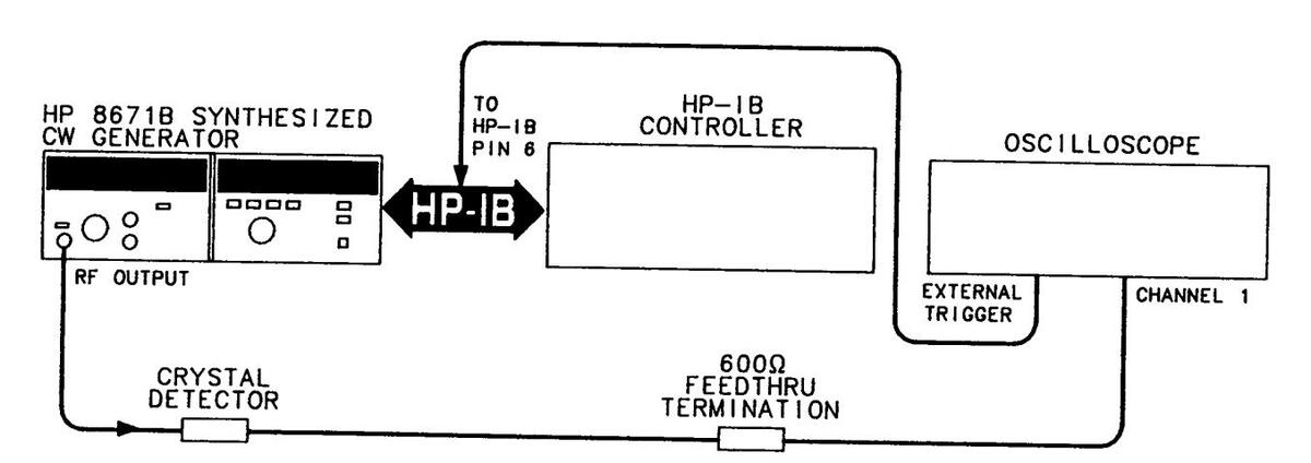
Figure 4-7. Output Level Switching Time Test Setup
| quipment | Oscilloscope | HP 1980B |
|---|---|---|
| HP-IB Controller | ||
| Crystal Detector | HP 8470B Opt. 012 | |
| 600Ω Feedthru Termination | HP 11095A |
Procedure
c
1. Set up the equipment as shown in Figure 4-7. The external trigger input of the oscilloscope should be connected to pin 6 of the HP-IB cable or A2A9U14, pin 15. An HP-IB adapter (HP 10834A) can be used to make a permanent trigger adapter for this test.

To access A2A9U14 the instrument's protective cover must be removed. This should be performed only by service-trained personnel who are aware of the hazards involved (for example, fire and electrical shock).
--------------------------------------
PERFORMANCE TESTS
OUTPUT LEVEL SWITCHING TIME TEST (cont'd)
Procedure 2. Set the oscilloscope for external triggering, positive trigger slope, triggered sweep mode (or NORM) and 2 ms per division sweep time.
NOTE
The following programs are for the HP 9826 or HP 9836 controller. For use with the HP 85B controller, increase the wait statements by a factor of 1000. This is necessary because the HP 9826 and HP 9836 execute wait commands in seconds while the HP 85B executes wait commands in milliseconds.
3. Load and run the following HP-IB controller program. As the program is executing, adjust the trigger controls for a stable oscilloscope display.
- 10 CLEAR 719
- 20 OUTPUT 719: "A3000000Z103075"
- 30 GOTO 20
- 40 END
- 4. Press the pause key on the controller. Load the following HP-IB controller program.
| - Controller talk, CW Generator listen | ||
|---|---|---|
| 10 | SEND 7; MTA LISTEN 19 | |
| 20 | FOR X=1 TO 50 | 0 dB range Ext ALC |
| 30 | OUTPUT 7; "KO" | - 0 dB lange, EXTALO |
| 40 | WAIT .03 | — 30 for HP 85B (30 ms) |
| 50 | OUTPUT 7; "K" | — Ready for change to -110 dB Range |
| 60 | WAIT .7 | — 700 for HP 85B (700 ms) |
| 70 | OUTPUT 7;";" | |
| 80 | WAIT .05 | |
| 90 | NEXT X | |
| 100 | END |
<20 ms
PERFORMANCE TESTS
OUTPUT LEVEL SWITCHING TIME TEST (cont'd)
Procedure (cont'd)
NOTE
Run this program only as long as necessary to make the level switching measurements. This measurement cycles the attenuator which causes mechanical wear. The program limits the number of cycles to 50, however, if a digitizing oscilloscope is available only one cycle is needed.
5. Run the program and measure the switching time by observing the signal on the oscilloscope display. Refer to Figure 4-8.
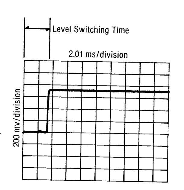
Figure 4-8. Output Level Switching Time Measurement Waveform
4-12. HARMONICS. SUBHARMONICS, & MULTIPLES TEST
Specification
| Electrical Characteristics | Performance Limits | Conditions |
|---|---|---|
| SPECTRAL PURITY | ||
|
Harmonics
Subharmonics and Multiples Thereof |
<−25 dBc
<−25 dBc |
Output level +8 dBm
Output level +8 dBm |
Description This test checks the amplitude of various harmonics of the CW Generator's output signal in the multiplied frequency bands (>6.2 GHz), subharmonics and multiples (harmonics of the internal fundamental signal) are also checked for specific levels. Reasonable care must be taken to ensure that the harmonics are not being generated by the spectrum analyzer.
- Equipment Spectrum Analyzer ....................................
- Procedure 1. Connect the CW Generator RF OUTPUT to the input of the spectrum analyzer as shown in Figure 4-9.
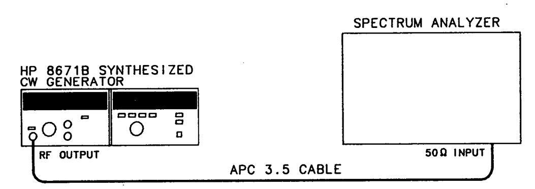
Figure 4-9. Harmonics, Subharmonics, and Multiples Test Setup
- 2. Tune the CW Generator to 4 000.000 MHz and output level of +8 dBm.
- 3. Set the spectrum analyzer controls to display the fundamental signal. Set the resolution bandwidth to 10 kHz and the input attenuation to 40 dB. Adjust the log reference level to set the displayed signal at the top graticule line of the display.
- 4. Tune the CW Generator to 2 000.000 MHz. The second harmonic, now displayed at 4 000.000 MHz, should be greater than 25 dB below the reference.
_____<-25 dBc
5. Repeat steps 2 through 4, at the other CW Generator frequencies listed, to check each harmonic, subharmonic, and multiple listed in the following table. Record the measurements in Table 4-3.
HARMONICS, SUBHARMONICS, & MULTIPLES TEST (cont'd)
Procedure (cont'd)
NOTE
This procedure may be repeated for any fundamental frequency of interest within the CW Generator frequency range.
Harmonics, Subharmonics, and Multiples
|
Set Signal
Generator to |
Check Harmonic Levels at: | |||
|---|---|---|---|---|
| FUNDAMENTAL | HARMONIC | SUBHA | RMONIC | MULTIPLE |
| (GHz) | (GHz) | 1/3 | 1/2 | 2/3 |
|
2.000 000
4.000 000 6.000 000 8.000 000 10.000 000 11.000 000 14.000 000 16.000 000 18.000 000 |
4.000 000
8.000 000 12.000 000 16.000 000 20.000 000 22.000 000 |
4.666 667
5.333 333 6.000 000 |
4.000 000
5.000 000 5.500 000 |
9.333 333
10.666 667 12.000 000 |
| LIMITS | <-25 dBc | -25 | dBc | |
HARMONICS, SUBHARMONICS, & MULTIPLES TEST (cont'd)
| Results | ||||
|---|---|---|---|---|
| Test | Min. | Actual | Max. | |
| Fundamental |
Harmonic
or Subharmonic |
|||
| 2.000 000 GHz | 4.000 000 GHz 2f | -25 dBc | ||
| 4.000 000 GHz | 8.000 000 GHz 2f | -25 dBc | ||
| 6.000 000 GHz | 12.000 000 GHz 2f | -25 dBc | ||
| 8.000 000 GHz | 16.000 000 GHz 2f | -25 dBc | ||
| 8.000 000 GHz | 4.000 000 GHz 1/2f | 25 dBc | ||
| 10.000 000 GHz | 20.000 000 GHz 2f | -25 dBc | ||
| 10.000 000 GHz | 5.000 000 GHz 1/2f | -25 dBc | ||
| 11.000 000 GHz | 22.000 000 GHz 2f | -25 dBc | ||
| 11.000 000 GHz | 5.000 000 GHz 1/2f | -25 dBc | ||
| 14.000 000 GHz | 4.666 667 GHz 1/3f | -25 dBc | ||
| 14.000 000 GHz | 9.33 3333 GHz 2/3f | −25 dBc | ||
| 16.000 000 GHz | 5.333 333 GHz 1/3f | −25 dBc | ||
| 16.000 000 GHz | 10.666 667 GHz 2/3f | -25 dBc | ||
| 18.000 000 GHz | 6.000 000 GHz 1/3f | -25 dBc | ||
| 18.000 000 GHz | 12.000 000 GHz 2/3f | -25 dBc | ||
Table 4-3. Harmonics, Subharmonics & Multiples Test Record
4-13. NON-HARMONICALLY RELATED SPURIOUS SIGNALS TEST
Specification
| Electrical Characteristics | Performance Limits | Conditions | |
|---|---|---|---|
| SPECTRAL PURITY | |||
|
Spurious
Non-Harmonically Related |
<-70 dBc
<-64 dBc <-60 dBc |
2.0 to 6.2 GHz
6.2 to 12.4 GHz 12.4 to 18.0 GHz |
Description
ion This test checks for any spurious signals in the CW Generator's RF output signal. The spectrum analyzer is calibrated for a reference level of -50 dBc and is tuned to any frequency from 2.0 to 6.2 GHz in search of spurious signals.
NOTE
The non-harmonically related spurious signals will always increase in amplitude above 6.2 GHz, due to multiplication in the internal YIG tuned multiplier. The increase is determined by a strict mathematical relationship. Therefore, satisfactory performance in the 2 to 6.2 GHz range will always ensure meeting the less stringent specification in the multiplied ranges, that is, from 6.2 to 18.0 GHz.
- Equipment Spectrum Analyzer ..... HP 8566B
- Procedure 1. Connect the CW Generator's RF OUTPUT to the input of the spectrum analyzer as shown in Figure 4-10.
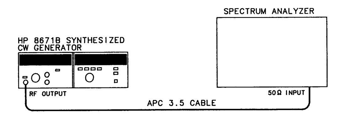
Figure 4-10. Non-Harmonically Related Spurious Signals Test Setup
- 2. Tune the CW Generator to 3 000.000 MHz and set the output level to -50 dBm.
- 3. Set the spectrum analyzer controls to display the fundamental signal. Set the resolution bandwidth to 1 kHz and the frequency span per division to 10 kHz.
- 4. Set the spectrum analyzer controls so that the carrier signal is at the top graticule line.
NON-HARMONICALLY RELATED SPURIOUS SIGNALS TEST (cont'd)
Procedure
(cont'd)
- 5. Using the RANGE selector, increase the CW Generator's output level to 0 dBm. Do not adjust the spectrum analyzer amplitude calibration. The top graticule line now represents -50 dBc.
- 6. Tune the spectrum analyzer to any desired frequency in search of non-harmonically related spurious signals. Verify that any signals found are non-harmonically related and are not generated by the spectrum analyzer. Verify that the spurious signals are below the specified limits. Record the results.
| Carrier Frequency |
Spurious Signal
Frequency |
Spurious Signal
Level |
|---|---|---|
|
3 000 MHz
3 000 MHz |
7. Repeat step 2 through 6 for any desired carrier frequency from 2 000.000 to 6 199.999 MHz. Record the results. (Checking non-harmonically related spurious signals from 2.0 to 6.2 GHz provides a high level of confidence that the instrument meets its published specifications from 2 to 18 GHz.)
| Carrier Frequency |
Spurious Signal
Frequency |
Spurious Signal
Level |
|---|---|---|
4-14. POWER LINE RELATED SPURIOUS SIGNALS TEST
Specification
| Electrical Characteristics | Performance Limits | Conditions |
|---|---|---|
|
SPECTRAL PURITY
Power line related and fan rotation related within 5 Hz below line frequencies and multiples theref |
-50 dBc
-60 dBc |
2.0—6.2 GHz
<300 Hz offset from carrier 300 Hz to 1 kHz offset from carrier |
| maniples theroi |
65 dBc
44 dBc 54 dBc 59 dBc |
|
|
40 dBc
50 dBc 55 dBc |
12.4—18.0 GHz
<300 Hz offset from carrier 300 Hz to 1 kHz offset from carrier >1 kHz offset from carrier |
Description The Unit Under Test and local oscillator are isolated from vibration by placing the instruments on two-inch thick foam pads. This eliminates the effects of microphonic spurious signals due to vibrations.
The primary power source is isolated from the power source used for the spectrum analyzer and the local oscillator to differentiate the power line related spurious signals from other power line related spurious signals.
NOTE
The Unit Under Test must be operated at a power line frequency different than that of the local oscillator and spectrum analyzer. This avoids the summing of the power line spurious signals.
| Equipment | Local Oscillator | HP 8340A |
|---|---|---|
| Spectrum Analyzer | HP 3580A | |
|
Mixer
Variable Frequency AC Power Source |
RHG DMS1-18
501TC/800T, California Instrumente |
|
| Camorina mor uniento |
Procedure 1. Place the CW Generator on a 2-inch foam pad. Connect the equipment as shown in Figure 4-11.
NOTE
Connect the mixer directly to the local oscillator to avoid any power loss.

POWER LINE RELATED SPURIOUS SIGNALS TEST (cont'd)

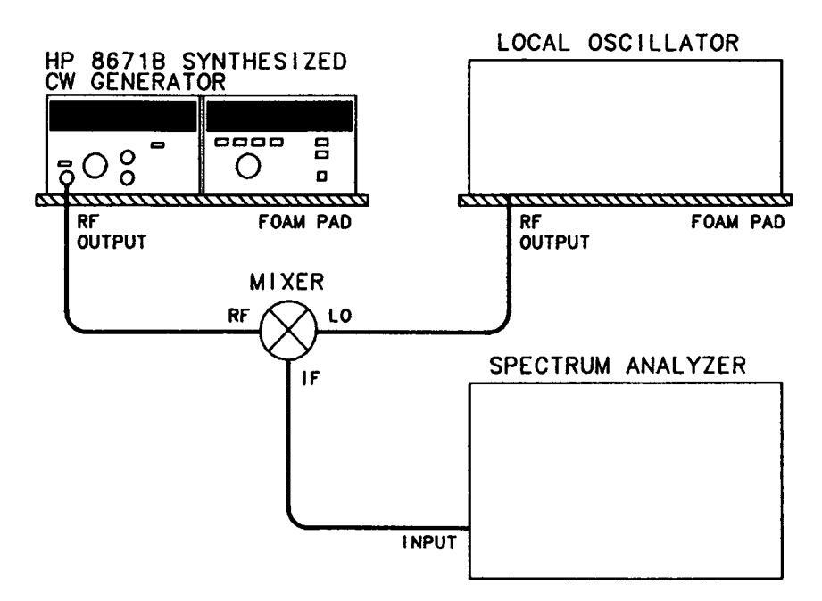
Figure 4-11. Power Line Related Sourious Signals Test Setup
- 2. Tune the CW Generator to 3 000.000 MHz and set the output level to -20 dBm.
- 3. Set the local oscillator to 3 000.020 MHz at +7 dBm.
- 4. Set the spectrum analyzer start frequency to 20 kHz, resolution bandwidth to 3 Hz.
- 5. Set the spectrum analyzer frequency span per division to 50 Hz. Set the spectrum analyzer controls so the peak of the 20 kHz signal is at the top graticule line. Verify that the line related spurious signals of the CW Generator do not exceed the values shown below. Record the highest spurious signal level in each offset band.
2.0 - 6.2 GHz <300 Hz offset ______-50 dBc
300 Hz — 1 kHz offset ______ -60 dBc
6. Set the spectrum analyzer frequency span per division to 500 Hz. Measure and record the highest spurious signal level.
2.0 - 6.2 GHz >1 kHz offset _____ -65 dBc
7. Tune the CW Generator and the local oscillator to 7000.000 MHz and 7000.020 MHz respectively.
POWER LINE RELATED SPURIOUS SIGNALS TEST (cont'd)
Procedure (cont'd) 8. Set the spectrum analyzer frequency span per division to 50 Hz. Set the spectrum analyzer controls so that the peak of the 20 kHz signal is at the top graticule line. Verify that the line related spurious signals of the CW Generator do not exceed the values shown below. Record the highest spurious signal level in each offset band.
6.2 - 12.4 GHz <300 Hz offset frequency _____ -44 dBc
300 Hz – 1 kHz offset frequency ______ -54 dBc
9. Set the spectrum analyzer frequency span per division to 500 Hz. Measure and record the spurious signal levels.
6.2 - 12.4 GHz >1 kHz offset frequency _____ -59 dBc
- 10. Tune the CW Generator and the local oscillator to 16 000.000 MHz and 16 000.020 MHz respectively.
- 11. Set the spectrum analyzer frequency span per division to 50 Hz. Set the spectrum analyzer controls so that the 20 kHz signal is at the top graticule line. Verify that the line related spurious signals of the CW Generator do not exceed the values shown in the table. Record the highest spurious signal level in each offset band.
12.4 - 18.0 GHz <300 Hz offset frequency _____ -40 dBc
300 Hz — 1 kHz offset frequency _____ -50 dBc
12. Set the spectrum analyzer frequency span per division to 500 Hz. Measure and record the spurious signal levels.
12.4 - 18.0 GHz >1 kHz offset frequency _____ -55 dBc
4-15. SINGLE-SIDEBAND PHASE NOISE TEST
Specification
| Electrical Characteristics | Performance Limits | Conditions |
|---|---|---|
| SPECTRAL PURITY | ||
| Single-sideband | . • | 2.0 — 6.2 GHz |
| Phase Noise | -58 dBc | 10 Hz offset from carrier |
| (1 Hz bandwidth) | -70 dBc | 100 Hz offset from carrier |
| · | -78 dBc | 1 kHz offset from carrier |
| -86 dBc | 10 kHz offset from carrier | |
| -110 dBc | 100 kHz offset from carrier | |
| 6.2 — 12.4 GHz | ||
| -52 dBc | 10 Hz offset from carrier | |
| -64 dBc | 100 Hz offset from carrier | |
| -72 dBc | 1 kHz offset from carrier | |
| -80 dBc | 10 kHz offset from carrier | |
| -104 dBc | 100 kHz offset from carrier | |
| 12.4 — 18.0 GHz | ||
| -48 dBc | 10 Hz offset from carrier | |
| -60 dBc | 100 Hz offset from carrier | |
| -68 dBc | 1 kHz offset from carrier | |
| -76 dBc | 10 kHz offset from carrier | |
| -100 dBc | 100 kHz offset from carrier |
Description The RF output of the CW Generator is mixed with a local oscillator to obtain a 40 kHz or 200 kHz IF signal. The phase noise sidebands are observed on a spectrum analyzer. Correction factors are applied to compensate for using the spectrum analyzer in the log mode, for local oscillator noise contributions, and for using bandwidths wider than 1 Hz.
NOTE
Normally, phase quadrature needs to be maintained between the CW Generator and the local oscillator for true phase noise measurement. However, the additional amplitude noise components are so small that they are not significant in these tests.
| Equipment | Local Oscillator | HP 8340A |
|---|---|---|
| ••• | Low Frequency Spectrum Analyzer | HP 3580A |
| High Frequency Spectrum Analyzer | HP 8566B | |
| Mixer | RHG DMS1-18 |
SINGLE-SIDEBAND PHASE NOISE TEST (cont'd)
NOTE
The signal-to-phase noise ratio as measured must be corrected to compensate for 3 errors contributed by the measurement system. These are
a. Using the spectrum analyzer in the log mode requires a +2.5 dB correction.
b. Equal noise contributed by the local oscillator requires a -3 dB correction.
c. The spectrum analyzer noise measurement must be normalized to a 1 Hz noise equivalent bandwidth. The noise equivalent bandwidth for HP spectrum analyzers is 1.2 times the 3 dB bandwidth.
For a 3 Hz bandwidth, the correction factor for the normalized measurement bandwidth would be:
Normalizing Factor dB = 10 log (1.2 × 3 Hz/1Hz) = 5.56 dB.
The total correction for 3 Hz bandwidth would be:
True measurement (dBc) = Reading (dBc) - 5.56 + 2.5 - 3 = Reading (dBc) - 6.06 dB.
Procedure 1. Set the low frequency spectrum analyzer's start frequency to 40 kHz, resolution bandwidth to 1 Hz, and frequency span per division to 5 Hz.
2. Connect the equipment as shown in Figure 4-12.
NOTE
Connect the mixer directly to the local oscillator to avoid any power loss.
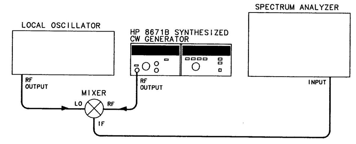

3. Tune the CW Generator to 6 100.000 MHz and set the output level to -20 dBm.
4. Set the local oscillator to 6 100.040 MHz at +8 dBm.
SINGLE-SIDEBAND PHASE NOISE TEST (cont'd)
Procedure (cont'd)
-
5. Set the spectrum analyzer controls so that the peak of the 40 kHz signal is at the top graticule line.
- 6. Observe the phase noise level 10 Hz from the carrier. It should be greater than 56.7 dB below the carrier. Record the measured level.
Measured _____ Correction -1.30 dB Actual level _____<-58 dBc
- 7. Tune the CW Generator and the local oscillator to 12 200.000 MHz and 12 200.040 MHz respectively.
- 8. Observe the phase noise level 10 Hz from the carrier. It should be greater than 50.07 dB below the carrier. Record the measured level.
Measured _____ Correction -1.30 dB Actual level <-52 dBc
- 9. Tune the CW Generator and the local oscillator to 18 000.000 MHz and 18 000.039 MHz respectively.
- 10. Observe the noise level 10 Hz from the carrier. It should be greater than 46.7 dB below the carrier. Record the measured level.
Measured _____ Correction -1.30 dB Actual level _____<-48 dBc
- 11. Set the spectrum analyzer controls for a resolution bandwidth of 3 Hz and a frequency span per division of 20 Hz. Using a 3 Hz bandwidth requires a 6.06 dB correction factor.
- 12. Repeat steps 3 through 10 except observe the noise 100 Hz from the carrier. Record the results below.
| Frequency | Measured | Correction | Actual | Limit |
|---|---|---|---|---|
|
6100.000 MHz
12 200.000 MHz 18 000.000 MHz |
-6.06 dB =
-6.06 dB = -6.06 dB = |
70 dBc
64 dBc 60 dBc |
- 13. For the remainder of this procedure, use the high frequency spectrum analyzer. Set the spectrum analyzer resolution bandwidth to 30 Hz and frequency span per division to 200 Hz. The 30 Hz bandwidth requires 16.06 dB correction.
- 14. Tune the CW Generator and the local oscillator to 6 100.000 MHz and 6 100.200 MHz respectively.
SINGLE-SIDEBAND PHASE NOISE TEST (cont'd)
Procedure (cont'd)
15. Tune the spectrum analyzer to place the 200 kHz IF signal at the left edge of the display. Set the spectrum analyzer controls to place the peak of the signal at the top graticule line. Increase the log reference level control to move the peak of the carrier 20 dB above the top graticule line. (The top graticule line is now -20 dBc.)
16. Observe the phase noise level 1 kHz from the carrier. The observed level should be greater than 62 dB below the carrier. Record the measured level
Measured _____ Correction -16.06 dB Actual Level _____<-78 dBc
17. Tune the CW Generator and the local oscillator to 12 200.000 MHz and 12 200.200 MHz respectively.
18. Observe the noise level 1 kHz from the carrier. The observed level should be greater than 56 dB below the carrier. Record the measured level.
Measured _____ Correction -16.06 dB Actual Level _____<-72 dBc
- 19. Tune the CW Generator and the local oscillator to 18 000.000 MHz and 18 000.200 MHz respectively.
- 20. Observe the noise level 1 kHz from the carrier. The observed level should be greater than 52 dB below the carrier. Record the measured level.
Measured ______ Correction -16.06 dB Actual Level _____<-68 dBc
- 21. Set the spectrum analyzer for a resolution bandwith of 300 Hz and a frequency span per division of 2 kHz. Using a 300 Hz bandwidth requires a 26.06 dB correction factor.
- 22. Repeat steps 14 through 20 except observe the noise 10 kHz from the carrier. Record the results below.
| E | T | |||
|---|---|---|---|---|
| Frequency | Measured | Correction | Actual | Limit |
|
6100.000 MHz
12 200.000 MHz 18 000.000 MHz |
-26.06 dB
-26.06 dB = -26.06 dB = |
86 dBc
80 dBc 76 dBc |
23. Set the spectrum analyzer controls for a resolution bandwidth of 3 kHz and a frequency span per division of 20 kHz. Using a 3 kHz bandwidth requires a 36.06 dB correction factor.
SINGLE-SIDEBAND PHASE NOISE TEST (cont'd)
Procedure (cont'd)
24. Repeat steps 14 through 20 except observe the noise 10 kHz from the carrier. Record the results below.
| Frequency | Measured | Correction | Actual | Limit |
|---|---|---|---|---|
|
6100.000 MHz
12 200.000 MHz 18 000.000 MHz |
-36.06 dB =
-36.06 dB = -36.06 dB = |
-110 dBc
-100 dBc -100 dBc |
4-16. INTERNAL TIME BASE AGING RATE
Specification
| Electrical Characteristics | Performance Limits | Conditions |
|---|---|---|
|
FREQUENCY
Reference Oscillator Frequency Aging Rate |
10 MHz
<5 x 10 -10 /day |
After a 10 day warmup
(typically 24 hours in a normal operating |
| Accuracy and Stability | Same as reference oscillator | environment) |
Description A reference signal from the CW Generator (10 MHz OUT) is connected to the oscilloscope's vertical input. A frequency standard (with long term stability greater than 1 × 10⁻¹⁰) is connected to the trigger input. The time required for a specific phase change is measured immediately and after a period of time. The aging rate is inversely proportional to the absolute value of the difference in the measured times.
| Equipment | Frequency Standard | HP 5065A |
|---|---|---|
| Oscilloscope | HP 1980B |
NOTE
Be sure the CW Generator has had 10 days to warm up before beginning this test. If the CW Generator was disconnected from the power line for less than 24 hours, only a 24 hour warm-up is needed.
Procedure
2 1. Set the rear panel FREQ REFERENCE INT-EXT switch to the INT position.
2. Connect the equipment as shown in Figure 4-13.
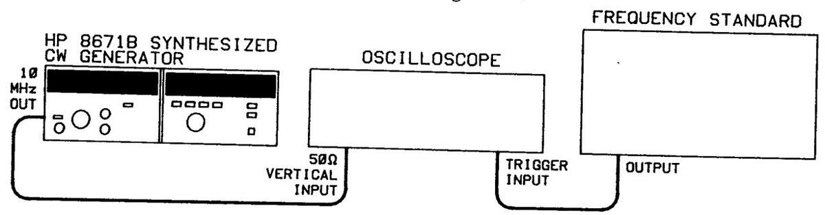
Figure 4-13. Internal Time Base Aging Rate Test Setup
3. Adjust the oscilloscope controls for a stable display of the 10 MHz CW Generator output.
INTERNAL TIME BASE AGING RATE (cont'd)
Procedure 4. Measure the time required for a phase change of 360°. Record the time (T1) in seconds.
T1 = _____s
5. Wait for a period of time (from 3 to 24 hours) and re-measure the phase change time. Record the period of time between measurements (T2) in hours and the new phase change time (T3) in seconds.
T3 = _____s
6. Calculate the aging rate from the following equation:
Aging Rate =
-
where: 1 cycle = the phase change reference for the time measurement (in this case, 360°)
- f = CW Generator's reference output frequency (10 MHz)
- T = specified time for aging rate (24h)
- T1 = initial time measurement(s) for a 360° (1 cycle) change
- T1 time between measurements (h)
- T3 = final time measurement(s) for a 360° (1 cycle) change
for example:
f
then:
Aging Rate = = 1.306 × 10 -11
7. Verify that the aging rate is less than 5 × 10⁻¹⁰.
NOTE
If the absolute frequencies of the frequency standard and the CW Generator's reference oscillator are extremely close, the measurement time in steps 5 and 6 (T1 and T3) can be reduced by measuring the time required for a phase change of something less than 360°. Change 1 cycle in the formula (i.e., 180° = 1/2 cycle, 90° = 1/4 cycle).
Aging Rate _____<5×10⁻¹⁰/day
1
Table 4-4. Performance Test Record (1 of 6)
|
lodel 867
vnthesiz |
71B
ved CW Generator |
Tested by | ||||
|---|---|---|---|---|---|---|
| erial Nu | mber | Date | ||||
| ara | T 1 | Results | ||||
| lo. | 1 631 | Min. | Actual | Max. | ||
| -7. | FREQUENCY RANGE AND RESOLUTION TEST | |||||
| Range (MHz) | ||||||
| Baseband Test | 3 000.000 | 2 999 999 | 3 000 001 | |||
| 2 000.000 | 1 999 999 | 2 000.00 | ||||
| 2 000.001 | 2 000 000 | 2 000.00 | ||||
| 2 001.112 | 2 001.111 | 2 000.00 | ||||
| 2 002.223 | 2 002.222 | 2 002 22 | ||||
| 2 003.334 | 2 003.333 | 2 003 33 | ||||
| 2 004.445 | 2 004.444 | 2 004 44 | ||||
| 2 005.556 | 2 005.555 | 2 005.55 | ||||
| 2 006.667 | 2 006.666 | 2 006.668 | ||||
| 2 007.778 | 2 007.777 | 2 007.77 | ||||
| 2 008.889 | 2 008.888 | 2 008.890 | ||||
| 2 009.999 | 2 009.998 | 2 010.000 | ||||
| 2090.000 | 2089.999 | 2090.001 | ||||
| 2 280.000 | 2 279.999 | 2 280.00 | ||||
| 2 470.000 | 2 469.999 | 2 470.001 | ||||
| 2 660.000 | 2 659.999 | 2 660.00 | ||||
| 2 850.000 | 2 849.999 | 2 850.001 | ||||
| 3 040.000 | 3 039.999 | _ | 3 040.001 | |||
| 3 230.000 | 3 229.999 | 3 230.001 | ||||
|
5 420.000
2 610 000 |
3 419.999 | · | 3 420.001 | |||
| 3 010.000 | 3 609.999 | 3 610.001 | ||||
| 3 000.000 | 3 799.999 | 3 800.001 | ||||
|
0 990.000
1 180 000 |
3 989.999 | 3 990.001 | ||||
| 4 100.000 | 4 1 / 9.999 | 4 180.001 | ||||
| 4 560 000 | 4 509.999 | 4 370.001 | ||||
| · | 4 750 000 | 4 33 3 | 4 000.001 | |||
| 4 940.000 | 4 939 999 | 4 750.001 | ||||
| 5 130.000 | 5 129 999 |
4 940.001
5 190.001 |
||||
| 5 320.000 | 5 319 999 | 5 390 001 | ||||
| 5 510.000 | 5 509.999 | 5 510 001 | ||||
| 5 700.000 | 5 699.999 | 5 700 001 | ||||
| 5 900.000 | 5 899.999 | 5 900 001 | ||||
| 6 100.000 | 6 099.999 | 6 100.001 | ||||
| Ba | ands 2 and 3 Test 10 GHz, | 2 kHz Resolution | (\scale) | |||
| 18 GHz, | 3 kHz Resolution | |||||
4-38
Table 4-4. Performance Test Record (2 of 6)
| • | ||||
|---|---|---|---|---|
|
Para.
No. |
lest | Min. | Actual | Max. |
| 4-8. | FREQUENCY SWITCHING TIME TEST | |||
|
Frequency Switching
18 GHz to 2.1 GHz 2.1 GHz to 18 GHz |
15 ms
15 ms |
|||
|
Amplitude Recovery
2.1 to 6.1 GHz, 1 kHz resolution band 6.2 to 12.3 GHz, 2 kHz resolution band 12.4 to 18.0 GHz, 3 kHz resolution band |
15 ms
15 ms 15 ms |
|||
| 4-9. | OUTPUT LEVEL, HIGH LEVEL ACCURACY AND FLATNESS TEST | |||
| Output Level | ||||
|
Frequency and Power at Minimum Power Point
2.0—18.0 GHz Frequency Minimum power |
+8 dBm | |||
|
Level Flatness (total variation)
2.0—6.2 GHz 2.0—12.4 GHz 2.0—18.0 GHz |
1.50 dB
2.00 dB 2.50 dB |
|||
| High Level Accuracy | ||||
|
+8 dBm (+10 dB range) 2 GHz
4 GHz 6 GHz 8 GHz 10 GHz 12 GHz 14 GHz 16 GHz 18 GHz |
+6.25 dBm
+6.25 dBm +6.25 dBm +6.00 dBm +6.00 dBm +6.00 dBm +5.75 dBm +5.75 dBm +5.75 dBm |
+ 9.75 dBm
+ 9.75 dBm + 9.75 dBm +10.00 dBm +10.00 dBm +10.00 dBm +10.25 dBm +10.25 dBm +10.25 dBm |
||
|
+3 dBm (+10 dB range) 2 GHz
4 GHz 6 GHz 8 GHz 10 GHz 12 GHz 14 GHz 16 GHz 18 GHz |
+1.25 dBm
+1.25 dBm +1.25 dBm +1.00 dBm +1.00 dBm +1.00 dBm +0.75 dBm +0.75 dBm +0.75 dBm |
+4.75 dBm
+4.75 dBm +5.00 dBm +5.00 dBm +5.00 dBm +5.25 dBm +5.25 dBm +5.25 dBm |
||
|
0 dBm (0 dB range)
2 GHz 4 GHz 6 GHz 8 GHz |
-1.75 dBm
-1.75 dBm -1.75 dBm -2.00 dBm |
+1.75 dBm
+1.75 dBm +1.75 dBm +2.00 dBm |
4-39
Table 4-4. Performance Test Record (3 of 6)
| Para. | Test | Results | |||
|---|---|---|---|---|---|
| No. | Min. | Actual | Max. | ||
| 4-9. |
OUTPUT LEVEL, HIGH LEVEL ACCURACY AND
FLATNESS TEST (cont'd) |
||||
| High Level Accuracy (confid) | |||||
| 0 dBm (0 dB range) (control) 10 GH | |||||
| 10 GHz | -2.00 dBm | +2.00 dBm | |||
| -2.00 dBm | +2.00 dBm | ||||
| 14 GHz | -2.25 dBm | +2.25 dBm | |||
| 18 GHz | -2.25 dBm | +2.25 dBm | |||
| - | -2.25 dBm | +2.25 dBm | |||
| -5 dBm (0 dB range) 2 GHz | -6 75 dBm | ||||
| 4 GHz | -6 75 dBm | -3.25 dBm | |||
| 6 GHz | -6 75 dBm | -3.25 dBm | |||
| 8 GHz | -7.00 dBm | -3.25 dBm | |||
| 10 GHz | -7.00 dBm | -3.00 dBm | |||
| 12 GHz | -7.00 dBm | -3.00 dBm | |||
| 14 GHz | -7.25 dBm | -2 75 dBm | |||
| 16 GHz | -7.25 dBm | -2.75 dBm | |||
| 18 GHz | -7.25 dBm | -2.75 dBm | |||
| -10 dBm (0 dB range) | |||||
| 2 GHz | -11.75 dBm | -8.25 dBm | |||
| -11.75 dBm | -8.25 dBm | ||||
|
o Gnz
8 CHz |
-11.75 dBm | -8.25 dBm | |||
| 10 GHz | -12.00 dBm | ····· | -8.00 dBm | ||
| 12 GHz | -12.00 dBm | -8.00 dBm | |||
| 14 GHz | -12.00 dBm | -8.00 dBm | |||
| 16 GHz | -12.25 dBm | -7.75 dBm | |||
| 18 GHz | -12.25 dBm | -7.75 dBm | |||
| -1.15 dBm | |||||
| -10 dBm (-10 dB range) 2 GHz | -12.25 dBm | -775 dBm | |||
| 4 GHz | -12.25 dBm | -7 75 dBm | |||
| 6 GHz | -12.25 dBm | -7.75 dBm | |||
| 8 GHz | -12.50 dBm | -7.50 dBm | |||
| 10 GHz | -12.50 dBm | -7.50 dBm | |||
| 12 GHz | -12.50 dBm | -7.50 dBm | |||
|
14 GHZ
16 CH- |
-12.85 dBm | -7.15 dBm | |||
| 1 |
10 GHz
18 CHz |
-12.85 dBm | -7.15 dBm | ||
| 10 0112 | -12.85 dBm | -7.15 dBm | |||
| -20 dBm (-20 dB range) 2 GHz | -99.45 dBm | ||||
| 4 GHz | -22.45 dBm | -17.55 dBm | |||
| 6 GHz | -22.45 dBm | -17.55 dBm | |||
| 8 GHz | -22.70 dBm | -17.55 dBm | |||
| 10 GHz | -22.70 dBm | -17 30 dBm | |||
| 12 GHz | -22.70 dBm | -17 30 dBm | |||
| 14 GHz | -23.05 dBm | -16.95 dBm | |||
| 16 GHz | -23.05 dBm | -16.95 dBm | |||
| 18 GHz | -23.05 dBm | -16.95 dBm | |||
| 1 | |||||
4-40
Table 4-4. Performance Test Record (4 of 6)
| Results | |||||
|---|---|---|---|---|---|
|
Para.
No. |
Ti | 281 | Min. | Actual | Max. |
| 4-10. | LOW LEVEL ACCURACY | ||||
| 2.0 GHz | |||||
| —30 dBm | -32.65 dBm | −27.35 dBm | |||
| -40 dBm | -42.95 dBm | -37.05 dBm | |||
| -50 dBm | -53.25 dBm | -46.75 dBm | |||
| -60 dBm | -63.55 dBm | -56.45 dBm | |||
| —70 dBm | -73.85 dBm | -66.15 dBm | |||
| -80 dBm | -84.15 dBm | -75.85 dBm | |||
| -90 dBm | -94.45 dBm | -85.55 dBm | |||
| -100 dBm | -104.75 dBm | -95.25 dBm | |||
| -110 dBm | -115.05 dBm | –104.95 dBm | |||
| 10.0 GHz | |||||
| -30 dBm | -32.90 dBm | -27.10 dBm | |||
| -40 dBm | -43.20 dBm | -36.80 dBm | |||
| -50 dBm | -53.50 dBm | -46.50 dBm | |||
| -60 dBm | -63.80 dBm | 56.20 dBm | |||
| -70 dBm | -74.10 dBm | 65.90 dBm | |||
| -80 dBm | -84.40 dBm | −75.60 dBm | |||
| 90 dBm | -94.70 dBm | -85.30 dBm | |||
| -100 dBm | -105.00 dBm | -95.00 dBm | |||
| —110 dBm | -105.30 dBm |
| −104.70 dBm
| |
|||
| 18.0 GHz | |||||
| 10.0 0112 | -30 dBm | -33.45 dBm | |||
| -40 dBm | -43.85 dBm | -36.15 dBm | |||
| 50 dBm | -54.25 dBm | -45.75 dBm | |||
| -60 dBm | -64.65 dBm | -55.35 dBm | |||
| -70 dBm | -75.05 dBm | -64.95 dBm | |||
| -80 dBm | -85.45 dBm | | −74.55 dBm | |||
| -90 dBm | 95.95 dBm | | −84.15 dBm | |||
| -100 dBm | -106.35 dBm | -93.75 dBm | |||
| -110 dBm | -107.75 dBm | | -103.35 dBm | |||
| 4-11. | OUTPUT LEVEL SWITCHING TI | ME | |||
| <20 ms | 20 ms | ||||
| 4-12. | HARMONICS, SUBHARMONICS, | AND MULTIPLES | |||
| Fundamental |
Harmonic or
Subharmonic |
||||
| 2 000000 CHz | 4 000000 GHz 9f | -25 dBc | |||
|
4.000000 G112 21
8 000000 GHz 9f |
-25 dBc | ||||
| 4.00000 GHz | 12.000000 GHz 2f | -25 dBc | |||
| 0.00000 0112 | 12.00000 GH2 21 |
Table 4-4. Performance Test Record (5 of 6)
| Para. | Test | Results | · | ||
|---|---|---|---|---|---|
| No. | Min. | Actual | Max. | ||
| 4-12. | HARMONICS, SUBHARM | ONICS, AND MULTIPLES (cont'd) | |||
| Harmonic or | |||||
| Fundamental | Subharmonic | ||||
| 8.000 000 GHz | 16.000 000 GHz 2f | -25 dBc | |||
| 8.000 000 GHz | 4.000 000 GHz 1/2f | -25 dBc | |||
| 10.000 000 GHz | 20.000 000 GHz 2f | -25 dBc | |||
| 10.000 000 GHz | 5.000 000 GHz 1/2f | -25 dBc | |||
| 11.000 000 GHz | 22.000 000 GHz 2f | -25 dBc | |||
| 11.000 000 GHz | 5.500 000 GHz 1/2f | -25 dBc | |||
| 14.000 000 GHz | 4.666 667 GHz 1/3f | ||||
| 14.000 000 GHz | 9.333 333 GHz 2/3f | j | |||
| 16.000 000 GHz | 5.333 333 GHz 1/3f | -25 dBo | |||
| 16.000 000 GHz | 10.666 667 GHz 2/3f | -25 dBc | |||
| 18.000 000 GHz | 6.000 000 GHz 1/3f | -25 dBc | |||
| 18.000 000 GHz | 12.000 000 GHz 2/3f | -25 dBc | |||
| 4-13. |
NON-HARMONICALLY RELA
(CW AND AM MODES) |
TED SPURIOUS SIGNALS | |||
| Carrier | Spurious Signal | Spurious Signal | |||
| Frequency | Frequency |
opurious orginal
Fevel |
|||
| 2.0 to 6.2 GHz | LOVUI | ||||
| 3 000 MHz | |||||
| -70 dBc | |||||
| -70 dBc | |||||
| -70 dBc | |||||
| −70 dBc | |||||
| -70 dBc | |||||
| -70 dBc | |||||
| 4-14. | POWER LINE RELATED SPUE | RIOUS SIGNALS | |||
| 20 62011- | Offset Frequency | ||||
| 2.0-0.2 GTZ | |||||
| SOO Hz 1 kHz offerst | -50 dBc | ||||
| >1 kHz offset | -60 dBc | ||||
| > 1 M112 011800 | 65 dBc | ||||
| 6.2—12.4 GHz | |||||
| <300 Hz offset | | | ||||
| 300 Hz—1 kHz offset | | | | -44 dBc | |||
| >1 kHz offset | -54 dBc | ||||
| -39 abc | |||||
| 12.4—18.0 GHz | |||||
| <300 Hz offset | -40 dBc | ||||
| 300 Hz—1 kHz offset | -50 dBc | ||||
| >1 kHz offset | -55 dBc | ||||
| Results | ||||
|---|---|---|---|---|
|
Para.
No. |
lest | Min. | Actual | Max. |
| 4-14. | SINGLE-SIDEBAND PHASE NOISE | |||
| 10 Hz offset from carrier 6100 MHz | -58 dBc | |||
| 12 200 MHz | -52 dBc | |||
| 18 000 MHz | 48 dBc | |||
| 100 Hz offset from carrier 6100 MHz | -70 dBc | |||
| 12 200 MHz | 64 dBc | |||
| 18 000 MHz | · | -60 dBc | ||
| 1 kHz offset from carrier 6100 MHz | -78 dBc | |||
| 12 200 MHz | -72 dBc | |||
| 18 000 MHz | 68 dBc | |||
| 10 kHz offset from carrier 6100 MHz | -86 dBc | |||
| 12 200 MHz | -80 dBc | |||
| 18 000 MHz | -76 dBc | |||
| 100 kHz offset from carrier 6100 MHz | -110 dBc | |||
| 12 200 MHz | -104 dBc | |||
| 18 000 MHz | -100 dBc | |||
| 4-15. | INTERNAL TIME BASE AGING RATE | 5 x 10 -10 /day | ||
Table 4-4. Performance Test Record (6 of 6)


 Loading...