

Page 1

User's Guide
HP 8572A EMI Receiver
ABCDE
08572-90003
No.
art
P
HP
Printed
in
USA
April
1992
Page 2

Notice
The information contained in this document is sub ject to change
without notice.
Hewlett-Packard makes no warrantyofany kind with regard to this
material, including, but not limited to, the implied warranties of
merchantability and tness for a particular purpose. Hewlett-Packard
shall not be liable for errors contained herein or for incidental
or consequential damages in connection with the furnishing,
performance, or use of this material.
Restricted Rights Legend.
Use, duplication, or disclosure by the U.S. Government is subject to
restrictions as set forth in subparagraph (c) (1) (ii) of the Rights
in Technical Data and Computer Software clause at DFARS
252.227-7013 for DOD agencies, and subparagraphs (c) (1) and (c)
(2) of the Commercial Computer Software Restricted Rights clause at
agencies.
other
F
AR
52.227-19
for
All
without prior
under
1400
c
Copyright Hewlett-Packard Company 1992
duction, adaptation,
Repro
Righ
the
oun
F
Reserv
ts
cop
tain
ed.
written
t
yrigh
v
Gro
ermission
p
ws.
la
arkw
P
e
y
a
is
, San
prohibited,
Rosa,
ta
or
except
95403-1799,
CA
translation
allo
as
USA
ed
w
Page 3

Certification
Hewlett-Packard Company certies that this product met its
published sp ecications at the time of shipment from the factory.
Hewlett-Packard further certies that its calibration measurements
are traceable to the United States National Institute of Standards
and Technology, to the extent allowed by the Institute's calibration
facility, and to the calibration facilities of other International
Standards Organization members.
Warranty
This Hewlett-Packard instrument pro duct is warranted against
defects in material and workmanship for a perio d of one year from
date of shipment. During the warranty perio d, Hewlett-Packard
Company will, at its option, either repair or replace products which
prove to be defective.
For warranty service or repair, this pro duct must be returned to a
y
prepa
shall
er
Buy
ard.
k
and
ard
and
try
coun
w
soft
instrumen
prop
not
w
rm
apply
ac
Hewlett-Pac
er.
Buy
to
for
taxes
.
rm
and
are
will execute
t
erly installed
that
t
arran
w
e
b
will
are
defects
to
kard
ev
w
Ho
ducts
pro
are
w
on
the
terrupted or
unin
resulting
shall pa
er
Buy
er,
returned
designated
that
eration
op
from
Hewlett-P
y
service
shipping
shipping
shall
to
Hewlett-P
b
its
instrumen
of
error-free.
Limit
facilit
harges
c
harges
c
all
y
pa
Hewlett-P
ac
Hewlett-P
y
programming
t.
instrumen
the
tion
a
foregoing
The
improper or inadequate maintenance byBuyer, Buyer-supplied
software or interfacing, unauthorized modication or misuse,
operation outside of the environmental specications for the
product, or improper site preparation or maintenance.
to
to
shipping
ard
k
ac
arran
w
ard
k
ard
k
ac
instructions
Hewlett-P
or
t,
arranty
W
of
arran
w
designated
y
b
Hewlett-P
return the
harges,
c
another
from
that
ts
with
use
for
ard
k
ac
are,
w
soft
shall
y
t
k
ac
product
duties,
its
an
when
es
do
or
not
y
IMPLIED.
EXPRESSED
ARRANTY
OTHER
NO
HEWLETT-P
IMPLIED W
FITNESS F
Exclusive Remedies
THE REMEDIES PR
AND EXCLUSIVE REMEDIES. HEWLETT-PACKARD SHALL
NOT BE LIABLE FOR ANY DIRECT, INDIRECT, SPECIAL,
INCIDENT
BASED
THEOR
W
CKARD
A
ARRANTIES OF MER
ARTICULAR PURPOSE.
AP
OR
OVIDED HEREIN ARE BUYER'S SOLE
CONSEQUENTIAL
OR
AL,
CONTRACT,
ON
Y.
IS
SPECIFICALL
CHANTABILITY AND
OR
T,
TOR
OR
Y DISCLAIMS
GES,
AMA
D
OTHER
ANY
THE
WHETHER
LEGAL
iii
Page 4

Assistance
Product maintenance agreements and other customer assistance
agreements are available for Hew lett-Packardproducts.
For any assistance, contact your nearest Hewlett-Packard Sales and
ServiceOce.
iv
Page 5
Safety Symbols
CAUTION
WARNING
DANGER
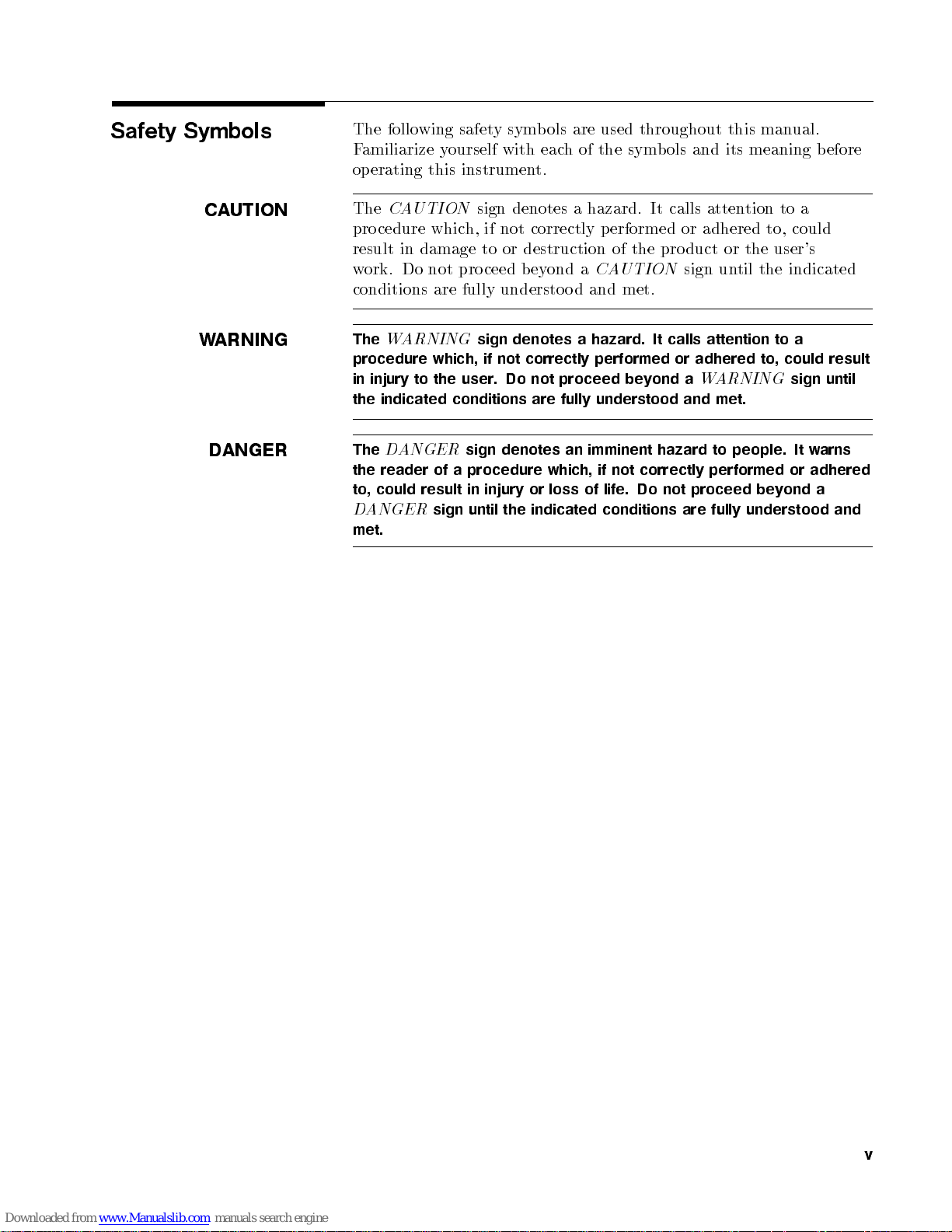
The following safety symbols are used throughout this manual.
Familiarize yourself with each of the symbols and its meaning before
operating this instrument.
The
CAUTION
procedure which, if not correctly performed or adhered to, could
result in damage to or destruction of the pro duct or the user's
work. Do not proceed beyond a
conditions are fully understoo d and met.
The
WARNING
procedure which, if not correctly performed or adhered to, could result
in injury to the user. Do not proceed beyond a
the indicated conditions are fully understood and met.
The
DANGER
the reader
result
could
to,
ANGER
D
met.
sign denotes a hazard. It calls attention to a
CAUTION
sign denotes a hazard. It calls attention to a
sign denotes an imminent hazard to people. It warns
not
of a
sign
procedure
injury
in
the
until
which,
loss
or
indicated
if
life.
of
conditions
sign until the indicated
WARNING
not
performed
proceed
fully
are
understood and
correctly
Do
bey
sign until
adhered
or
a
ond
v
Page 6
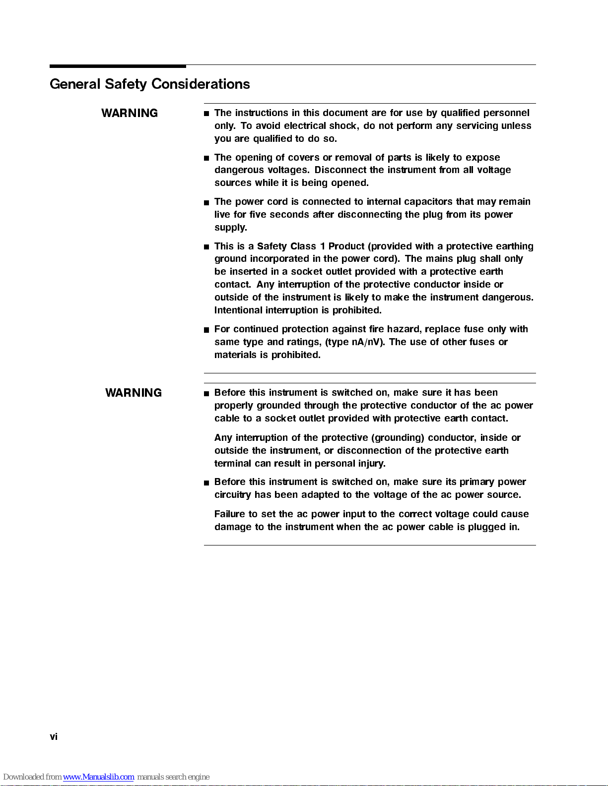
General Safety Considerations
WARNING
ARNING
W
The instructions in this document are for use by qualified personnel
only.Toavoid electrical shock, do not perform any servicing unless
you are qualified to do so.
The opening of covers or removal of parts is likely to expose
dangerous voltages. Disconnect the instrument from all voltage
sources while it is being opened.
The power cord is connected to internal capacitors that may remain
live for five seconds after disconnecting the plug from its power
supply.
This is a Safety Class 1 Product (provided with a protective earthing
ground incorporated in the power cord). The mains plug shall only
be inserted in a socket outlet provided with a protective earth
contact. Any interruption of the protective conductor inside or
fuse
fuses
has
of
contact.
dangerous.
only with
or
been
po
ac
the
er
w
outside
Intentional
For
same
materials
Before
properly
cable
of
continued
type and
this
to
instrument
the
interruption
protection
ratings, (type
prohibited.
is
instrument
grounded
et
sock
a
through
outlet
lik
is
prohibited.
is
against
switched
is
the
vided
pro
to
ely
fire
nA/nV).
on,
protectiv
with
e
mak
hazard,
The
mak
e
protectiv
instrument
the
replace
other
of
use
it
sure
e
conductor
eearth
inside
of the
conductor,
protective
(grounding)
interruption
Any
outside
terminal can
Before this instrument is switched on, make sure its primary power
circuitry has been adapted to the voltage of the ac power source.
Failure to set the ac power input to the correct voltage could cause
damage to the instrument when the ac power cable is plugged in.
the
of
instrument,
result in
or
personal
protectiv
the
e
disconnection
.
injury
or
earth
vi
Page 7
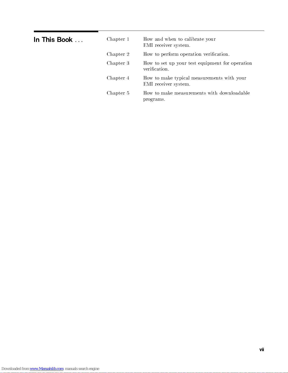
In This Book
...
Chapter 1 How and when to calibrate your
EMI receiver system.
Chapter 2 How to perform operation verication.
Chapter 3 How to set up your test equipment for operation
verication.
Chapter 4 Howtomaketypical measurements with your
EMI receiver system.
Chapter 5 Howtomake measurements with downloadable
programs.
vii
Page 8

Page 9
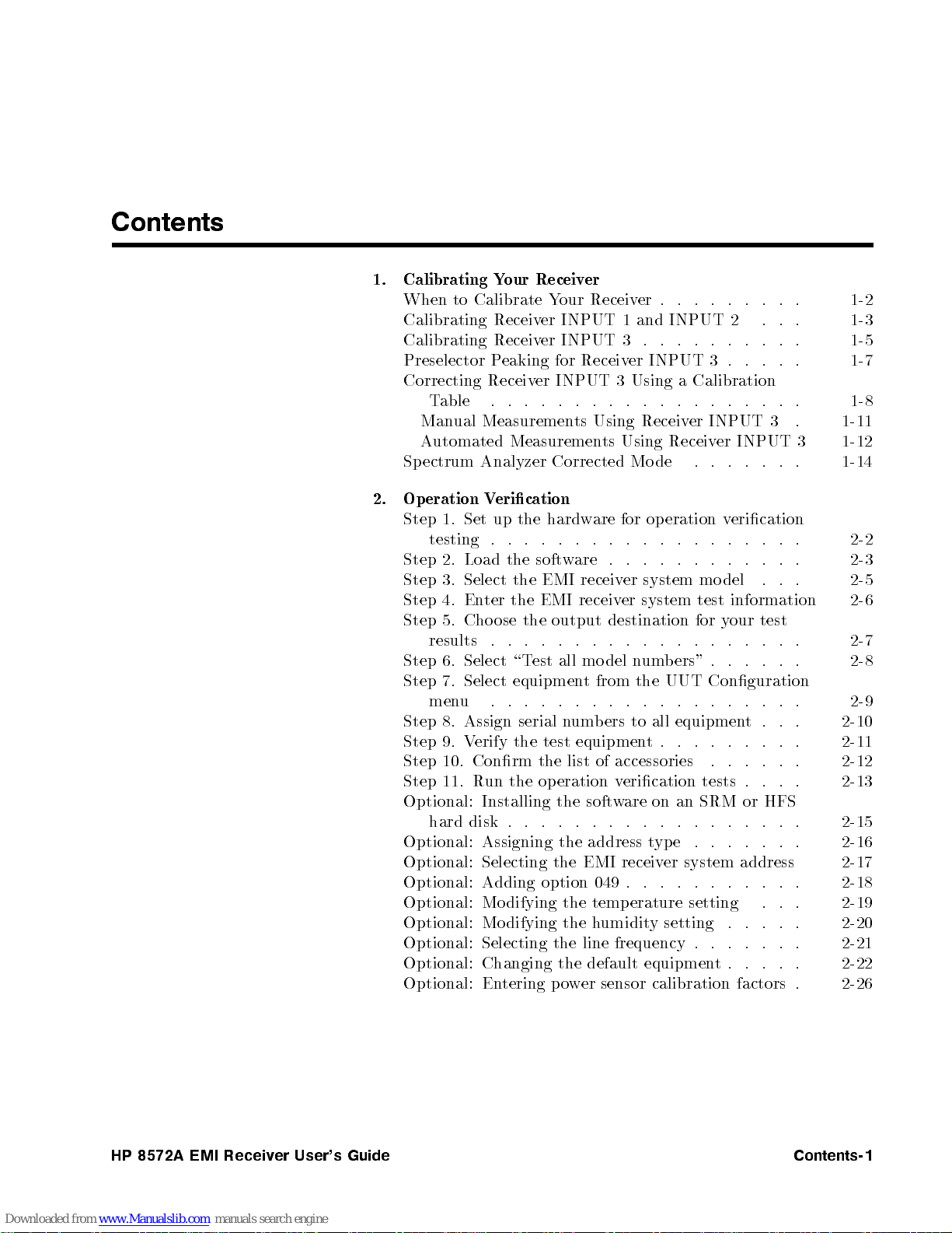
Contents
1. Calibrating Your Receiver
When to Calibrate Your Receiver . . . . . . . . . 1-2
Calibrating Receiver INPUT 1 and INPUT 2 . . . 1-3
Calibrating Receiver INPUT 3 . . . . . . . . . . 1-5
Preselector Peaking for Receiver INPUT 3 . . . . . 1-7
Correcting Receiver INPUT 3 Using a Calibration
Table . . . . . . . . . . . . . . . . . . . 1-8
Manual Measurements Using Receiver INPUT 3 . 1-11
Automated Measurements Using Receiver INPUT 3 1-12
Spectrum Analyzer Corrected Mode . . . . . . . 1-14
erication
1.
2.
3.
4.
5.
6.
7.
8.
9.
V
up
Set
.
Load
Select
ter
En
ose the
Cho
.
Select
Select
. .
Assign
erify
V
Selecting
Adding
hardw
the
. .
.
.
soft
the
EMI
the
EMI
the
output
.
.
.
.
all
est
\T
equipmen
.
.
.
serial
test
the
the
option
erication
eration
op
for
are
.
.
.
.
. .
.
.
.
.
are
w
system
er
receiv
system
er
receiv
destination
.
.
.
.
.
.
ers"
b
um
n
del
mo
UUT Conguration
the
from
t
.
.
.
.
.
.
equipmen
all
to
ers
b
um
n
.
equipmen
EMI receiv
049
wer sensor calibration factors .
t
er
.
.
.
umidity setting
v
.
.
.
.
.
.
.
.
.
.
.
.
.
del
mo
information 2-6
test
test
our
y
for
.
.
.
.
.
.
. .
.
.
.
.
.
.
.
.
.
t
. .
. .
. .
system
.
address
.
.
.
. .
. . . 2-19
. . . .
. . . . . . 2-21
. . . . 2-22
t.
.
.
.
.
.
.
.
.
. .
.
.
.
.
. .
.
.
. 2-20
eration
Op
2.
Step
testing
Step
Step
Step
Step
results
Step
Step
menu
Step
Step
Step 10. Conrm the list of accessories . . . . . . 2-12
Step 11. Run the operation verication tests . . . . 2-13
Optional: Installing the software on an SRM or HFS
hard disk . . . . . . . . . . . . . . . . . . 2-15
Optional: Assigning the address type . . . . . . . 2-16
Optional:
Optional:
Optional: Modifying the temp erature setting
Optional: Modifying the h
Optional: Selecting the line frequency .
Optional: Changing the default equipmen
Optional: Entering po
2-2
2-3
2-5
2-7
2-8
2-9
2-10
2-11
2-17
2-18
2-26
User's
HP
8572A
EMI
Receiv
er
Guide
Contents-1
Page 10

3. Test Descriptions
Calibrator Amplitude Accuracy . . . . . . . . . 3-2
Log Fidelity . . . . . . . . . . . . . . . . . . 3-5
Linear Fidelity. . . . . . . . . . . . . . . . . 3-7
Reference Level Switching Uncertainty . . . . . . 3-9
Receiver Calibration INPUT 1 . . . . . . . . . . 3-12
Amplitude Accy. INPUT 1 (10 dB AT and 0 dB AT),
20 Hz-9 kHz . . . . . . . . . . . . . . . . 3-15
Amplitude Accy. INPUT 1 (10 dB AT and 0 dB AT) 3-17
Disp. Average Noise INPUT 1 . . . . . . . . . . 3-19
Sensitivity INPUT 1, 20 Hz to 9 kHz . . . . . . . 3-21
Residual Responses INPUT 1 . . . . . . . . . . 3-23
Bandwidth Accuracy . . . . . . . . . . . . . . 3-25
Pulse Response . . . . . . . . . . . . . . . . . 3-28
Calibration INPUT 2 . . . . . . . . . . . . . . 3-33
Amplitude Accy. INPUT 2 (10 dB AT and 0 dB AT) 3-36
Disp. Average Noise INPUT 2 . . . . . . . . . . 3-39
Residual Responses INPUT 2 . . . . . . . . . . 3-41
.
.
.
.
.
.
.
.
.
.
INPUT
INPUT
3 .
3
RBW
Hz
10
,
3
.
.
.
.
.
. .
.
.
.
.
.
.
.
Amplitude Accy
erage
Disp.
Residual
Av
Resp
onses
. INPUT
Noise
3-43
3-48
3-50
ypical
Making
4.
esting
T
Narro
Commercial
CE03
RE02
CISPR
5. Downloadable Program (DLP) Measurements
Example: Quasi-peak measurements on broadband
Index
T
for
Linearity
dB
3
wband/Broadband
Detector
Measuremen
(MIL-STD)
(MIL-STD)
22
signals, using a DLP . . . . . . . . . . . . . 5-1
Measuremen
erload
Ov
Chec
Compliance
Selection
t Examples
Measuremen
Measuremen
Measuremen
k
ts
.
.
.
.
.
.
.
Signals
Measuremen
.
.
.
.
.
.
t
t
.
.
ts
. .
.
. .
.
.
.
.
.
.
.
.
.
.
.
.
.
.
.
.
.
.
ts
.
.
.
.
.
.
.
.
.
.
.
.
.
.
.
.
.
.
.
. .
. .
.
.
.
.
.
.
.
.
.
.
.
.
.
.
.
.
.
.
.
.
.
.
.
.
.
.
.
.
.
.
.
.
.
.
. 4-28
. .
4-1
4-2
4-2
4-5
4-5
4-9
4-23
4-26
Contents-2
HP
8572A
EMI
Receiv
er
User's
Guide
Page 11

Figures
1-1. Sample Calibration Table . . . . . . . . . . . 1-9
1-2. Calibration Data Graph . . . . . . . . . . . . 1-13
4-1. Testing for Overload . . . . . . . . . . . . . 4-1
4-2. Narrowband Spectrum . . . . . . . . . . . . 4-2
4-3. Broadband Sp ectrum . . . . . . . . . . . . . 4-3
4-4. Methods for Narrowband and Broadband Analysis 4-4
4-5. Signal Detection and Processing . . . . . . . . 4-6
4-6. Average Detection Using Video Filtering . . . . 4-7
4-7. Quasi-Peak Detection . . . . . . . . . . . . . 4-8
4-8. Quasi-Peak Detector Output . . . . . . . . . . 4-9
4-12
.
.
. .
Measuremen
eak
P
4-9.
Measurement
Peak
4-10.
Measuremen
osite
erage
T
o
t
est
eak
Measuremen
eak
Signal
Measuremen
er
w
Prob
Correction
Setup
Under
t
Measuremen
eak
Quasi-P
4-11.
Quasi-P
4-12.
Comp
4-13.
Av
4-14.
CE03 P
4-15.
Curren
4-16.
Bandwidth
4-17.
RE02
4-18.
4-19. Characteristic
Equipmen
4-20.
Quasi-P
5-1.
Lead
as
es
App
aCW
of
t
Broadband
of a
t
t
.
.
.
.
t
Setup
est
T
ransducers
T
actor
F
.
. .
earance
(EUT)
est
T
t
of
of
.
.
.
.
.
.
of
Using
Signal .
a
a
CW
Broadband
.
.
. .
(Air
.
.
.
.
Radiated
urned
T
the
. .
Signal
Signal
. .
.
.
.
.
.
.
and
orce
F
.
.
.
.
.
.
.
.
.
.
.
.
Emissions
O
HP 85867A
.
.
.
.
Signal
. .
.
.
Na
.
.
.
.
.
.
.
.
4-14
.
.
4-18
.
.
4-20
.
4-21
.
.
4-23
.
.
vy)
.
. .
.
.
DLP 5-3
4-24
4-25
.
4-26
4-27
.
4-30
.
4-30
.
Tables
User's
HP
8572A
EMI
Receiv
er
Guide
1-1. F
receiv
1-2.
2-1. T
2-2. T
INPUT
er
Bands
requency
est Equipmen
est Equipmen
.
.
.
. .
.
.
.
.
.
.
.
.
.
.
.
.
.
.
requency Bands
F
3
t . . . . . . . . . . . . . . .
tV
ariable
Names . . . . . . . . 2-24
.
.
.
Contents-3
1-7
1-10
2-23
Page 12

Page 13
Calibrating Your Receiver
In this chapter, you'll learn how and when to calibrate your
HP 8572A microwave EMI receiver:
how often to calibrate your receiver
how to calibrate receiver INPUT 1 and receiver INPUT 2
how to calibrate receiver INPUT 3
how to perform preselector peaking for receiver INPUT 3
how use a calibration table to calibrate receiver INPUT 3
1
ho
erform
p
to
w
man
automated
and
ual
measuremen
ts
User's
HP
8572A
EMI
Receiv
er
Guide
Calibrating
Y
our
Receiv
er
1-1
Page 14
When to Calibrate Your Receiver
Note
To meet specied absolute amplitude accuracy,your receiver must
be calibrated. For accurate calibration, ambient temperature must
be 20 to 30 degrees centigrade. Your receiver must be stabilized at
room temperature for at least two hours, to allow comb amplitude
to stabilize.
Calibrate your HP 8572A microwave EMI receiver:
at the start of eachday
after p ower is cycled on the RF preselector
for eachchange in:
resolution bandwidth
frequency band
uation
atten
should
also
ou
y
EMI
e
v
a
w
haracterization
c
mon
six
ery
ev
sp
its
meet
receiv
EMI
erify
v
er
receiv
all
and
be
to
ths
ecications.
system
er
the
dically
erio
p
EMI
sure
During
(including
the
to
of
RF
system
er
testing,
analyzer
CAL
these
the
preselector
p
system
ectrum
sp
logarithmic/linear scale
AMPTD
addition
In
erformance
p
Complete
er
receiv
receiv
EMI
erformance
p
cables).
preselector
or
setting
calibrations,
8572A
HP
com
erformance
tinues
con
the
use
micro
b
tests
to
tire
en
.
all
calibration
dic
erio
p
This
consuming.
time
e
b
can
and
erformance v
p
and
Hewlett-Packard service center.
erication is
requires
F
extensiv
our con
y
or
ailable through
av
equipmen
test
e
venience,
calibration
cal
lo
our
y
t,
1-2
Calibrating
Y
our
Receiv
er
HP
8572A
EMI
Receiv
er
User's
Guide
Page 15
Calibrating Receiver INPUT 1 and INPUT 2
Note
Receiver INPUT 1 and receiver INPUT 2 are input 1 and input 2
on the HP 85685A RF preselector.
When calibrating receiver INPUT 1 and receiver INPUT 2,
complete the pro cedure for each new combination of frequency
range, resolution bandwidth, logarithmic/linear scale, and
attenuation settings.
To calibrate receiver INPUT 1 and receiver INPUT 2:
1. Connect the 100 MHz CAL OUTPUT on the spectrum analyzer
to receiver INPUT 2 on the RF preselector.
2. On the quasi-peak adapter, select the bypass path by pressing
the BYPASS key in the INSTR FUNCTION group. The LED
t.
ligh
will
ey
k
that
e
v
o
ab
ASS
er;
the
the
LED
LED
the
On
3.
ENABLE
near receiv
Select
4.
SWITCHES
that
in
preselector
RF
4
5
er INPUT
preamplier
the
will
ey
k
y pressing
b
path
ypass
b
the
select
,
4
ASS
BYP
the
and
ey
k
t.
ligh
will
2
path
ypass
b
atten
the
4
0
ligh
on
ey
k
5
t.
ey;
k
5
pressing
y
b
uator/switc
the
h
BYP
the
driv
ectrum
4
Press
5.
Adjust
6.
0
Press
7.
Adjust
8.
signal on the display.
9. Select the frequency range, resolution bandwidth,
logarithmic/linear scale, and attenuator settings to be used for
the desired measurement.
Select
10.
Connect
11.
RF preselector to the receiv
12. Execute the com
4
If the start frequency is belo
display the 100 kHz comb signal and you will be instructed to adjust
AMPTD CAL on the spectrum analyzer for the displayed amplitude
the 100
of
calibration
adjustmen
no
automatically
10
START
RECALL
AMPTD
dBm
4
RECALL
FREQ ZER
the
on the RF preselector
5
kHz
signal
4
5
5
8
0.20
6
4
5
5
9
quasi-peak
COMB
the
b
com
amplitude
necessary;
is
t
.
on
CAL
dB
on the
b calibration sequence b
to
sp
the
the
on
.
spectrum
the sp
Oon
adapter
GENERA
w200
to
oth
is
the
er input to be calibrated.
within
within
calibration
analyzer.
of
the
on
the
If
the
for
maxim
a
for
measuremen
the
kHz
100
con
v
tin
desired
will
analyzer.
OUTPUT
dB
0.2
6
0.2
6
analyzer
for
y pressing CAL SEQ
.
dB
sequence
ectrum
sp
ectrum analyzer
bandwidth
TOR
.
kHz, the spectrum analyzer will
um
t.
alue,
ue
User's
HP
8572A
EMI
Receiv
er
Guide
Calibrating
Y
our
Receiv
er
1-3
Page 16
After adjusting AMPTD CAL to within60.2 dB, press
CAL SEQ
routine. If the stop frequency is ab ove 200 kHz , the calibration
sequence is performed over the frequency span ab ove200kHz.
The comb generator CAL SEQ LED ashes while the calibration
sequence is running. When the calibration sequence ends, the CAL
SEQ LED stays on, indicating that the system is calibrated over the
current frequency range. If the receiver frequency is increased beyond
the calibrated frequency range, the CAL SEQ LED turns o, to
indicate an uncalibrated state.
4
START
5
on the RF preselector to continue the calibration
Note
The CAL SEQ LED does not turn o when settings other than
start or stop frequency are changed. Therefore, it is possible for an
uncalibrated state to exist for the current settings of resolution
bandwidth, attenuation, or amplitude scale while the CAL SEQ
LED is turned on.
instrument settings.
hange
c
ou
y
If
uation,
atten
with the
or
new settings.
Be sure the receiver is calibrated for the current
resolution
readjust
bandwidth,
AMPTD
logarithmic/linear
CAL, rep
eat steps
9 through
scale,
or
12
1-4
Calibrating
Y
our
Receiv
er
HP
8572A
EMI
Receiv
er
User's
Guide
Page 17

Calibrating Receiver INPUT 3
Note
Receiver INPUT 3 is the preamplier input on the HP 8449B Opt
H02 preamplier.
When calibrating receiver INPUT 3,
Complete the calibration procedure for frequency range,
resolution bandwidth, logarithmic/linear scale, and attenuation
settings.
Apply amplitude correction factors from the calibration table on
page 1-10.
Execute a PRESEL PEAK (preselector peak) for eachsignalin
preselected band 1 through band 4 (2 GHz to 22 GHz).
To calibrate receiver INPUT 3:
ASS
er;
analyzer
LED
the
Connect the
1.
receiv
to
the
On
2.
ENABLE
near
Select
3.
SWITCHES
that
in
er
RF
receiv
the
ey
k
MHz
100
.
and
ey
k
INPUT
4
k
5
ligh
2
ey
t.
INPUT
preselector
4
5
er
preamplier
0
will
CAL
select
,
the
2will
ypass
b
the
on
OUTPUT
the
ASS
BYP
t.
ligh
path
atten
the
on
4
5
y
b
path b
ey;
k
pressing
bypass
uator/switc
the
ectrum
sp
y
BYP
the
driv
h
pressing
the
LED
Press
4.
5.
6.
7. Press
8. Adjust FREQ ZERO on the spectrum analyzer for maximum
9.
10. Press
11. T
Steps 1 through 6 perform a modied
adjustmen
step
in
trac
complete
4
RECALL
Select
settings
Adjust
0
trace
Press
until the LED turns o.
factor from the displa
Receiver INPUT 3 Using a Calibration Table").
king
the
for
AMPTD
10 dBm60.20 dB.
4
RECALL549
amplitude.
the
4
SHIFT54PRESEL PEAK
o correct for receiv
through
t
will
10
b
for
4
a
PRESEL
4
on the
5
5
8
resolution
measuremen
the
CAL
5
on the spectrum analyzer.
SWITCHES
the
optimize
erall
v
est o
PEAK
spectrum
bandwidth
t.
the sp
on
4
0
k
5
5
on the spectrum analyzer.
er frequency
yed signal amplitude. See \Correcting
path.
ypass
b
to
GHz
2
onse.
resp
h
eac
for
5
analyzer.
logarithmic/linear
and
ectrum analyzer
atten
the
on
ey
response, subtract the gain
4
RECALL548
Pressing
RF preselector
GHz
22
obtain
o
T
signal.
true
for
uator/switc
5
amplitude
4
SHIFT
5
signal
4
scale
h
PRESEL
lter
amplitude,
driv
PEAK
er
5
User's
HP
8572A
EMI
Receiv
er
Guide
Calibrating
Y
our
Receiv
er
1-5
Page 18

Note
If you change resolution bandwidth, or logarithmic/linear scale
settings, or readjust AMPTD CAL on the sp ectrum analyzer,
repeat this procedure with the new settings.
1-6
Calibrating
Y
our
Receiv
er
HP
8572A
EMI
Receiv
er
User's
Guide
Page 19
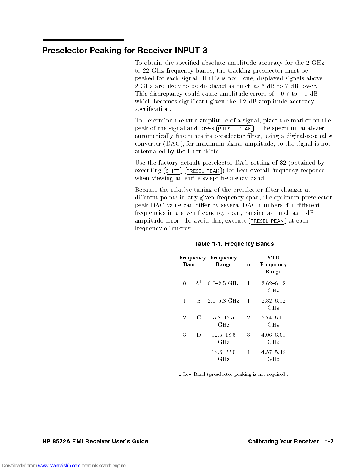
Preselector Peaking for Receiver INPUT 3
To obtain the specied absolute amplitude accuracy for the 2 GHz
to 22 GHz frequency bands, the tracking preselector must be
peaked for each signal. If this is not done, displayed signals above
2 GHz are likely to be displayed as much as 5 dB to 7 dB lower.
This discrepancy could cause amplitude errors of00.7 to01dB,
which becomes signicantgiven the62 dB amplitude accuracy
specication.
To determine the true amplitude of a signal, place the marker on the
peak of the signal and press
automatically ne tunes its preselector lter, using a digital-to-analog
converter (DAC), for maximum signal amplitude, so the signal is not
attenuated by the lter skirts.
Use the factory-default preselector DAC setting of 32 (obtained by
executing
when
4
SHIFT54PRESEL PEAK
en
viewing
an
tire
sw
4
PRESEL PEAK
5
) for best overall frequency resp onse
frequency
ept
5
. The spectrum analyzer
band.
Because
dieren
eak
p
frequencies
amplitude
frequency
the relativ
p
t
C
A
D
ts
oin
alue
v
in
error.
in
of
etuning
y
an
in
dier
can
given
a
a
o
T
terest.
T
requency
F
Band
A
0
1 B 2.0{5.8 GHz 1 2.32{6.12
2 C 5.8{12.5
3
4
of
frequency
en
giv
eral D
ysev
b
frequency span,
execute
this,
oid
v
1-1. Frequency
able
requency
F
Range
1
0.0{2.5
D
E 18.6{22.0
GHz
GHz
12.5{18.6
GHz
GHz
the
span,
um
n
C
A
causing
4
PRESEL
Bands
n
requency
F
Range
3.62{6.12
1
2 2.74{6.09
4.06{6.09
3
4.57{5.42
4
preselector
the
lter
optim
b
as
PEAK
YTO
GHz
GHz
GHz
GHz
GHz
ers,
m
hanges
c
um
for
h
uc
at
5
at
preselector
dieren
dB
1
as
h
eac
t
User's
HP
8572A
EMI
Receiv
er
Guide
1
Low Band (preselector peaking is
not required).
Calibrating
Y
our
Receiv
er
1-7
Page 20
Correcting Receiver INPUT 3 Using a Calibration Table
To obtain sp ecied absolute amplitude accuracy for signals
measured through receiver INPUT 3, apply the frequency-dep endent
correction factors to signal amplitude measurements. Because of the
preamplier gain, signals will be displayed on the receiver displayat
an amplitude higher than the actual signal amplitude.
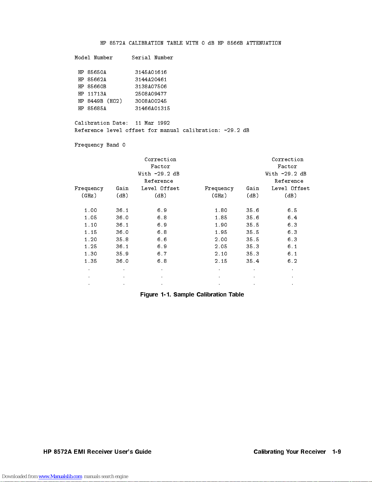
Figure 1-1 is a sample calibration table. The calibration data corrects
for preamplier gain, preamplier frequency response, and spectrum
analyzer frequency resp onse for both 0 dB and 10 dB spectrum
analyzer attenuation after the receiver calibration routine has been
completed. Calibration factors are provided every 50 MHz from
1.0 GHz to 22 GHz for each frequency band.
Calibration data is provided in two forms in the calibration table:
gain in dB, and correction factor with a specic reference level oset.
1-8
Calibrating
Y
our
Receiv
er
HP
8572A
EMI
Receiv
er
User's
Guide
Page 21
HP 8572A CALIBRATION TABLE WITH 0 dB HP 8566B ATTENUATION
Model Number Serial Number
HP 85650A 3145A01616
HP 85662A 3144A20461
HP 85660B 3138A07506
HP 11713A 2508A09477
HP 8449B (HO2) 3008A00245
HP 85685A 31466A01315
Calibration Date: 11 Mar 1992
Reference level offset for manual calibration: -29.2 dB
Frequency Band 0
Correction Correction
Factor Factor
With -29.2 dB With -29.2 dB
Reference
Frequency Gain
(GHz) (dB)
Level Offset
(dB) (GHz)
Frequency Gain
Reference
Level Offset
(dB) (dB)
1.00
1.05
1.10
1.15
1.20
1.25
1.30
1.35
.
.
.
36.1
36.0
36.1
36.0
35.8
36.1
35.9
36.0
.
.
. .
Figure
6.9
6.8
6.9
6.8
6.6
6.9
6.7
6.8
.
.
1-1.
Sample
1.80
1.85
1.90
1.95
2.00
2.05
2.10
2.15
.
.
. .
Calibration
able
T
35.6
35.6
35.5
35.5
35.5
35.3
35.3
35.4
.
.
6.5
6.4
6.3
6.3
6.3
6.1
6.1
6.2
.
.
.
User's
HP
8572A
EMI
Receiv
er
Guide
Calibrating
Y
our
Receiv
er
1-9
Page 22
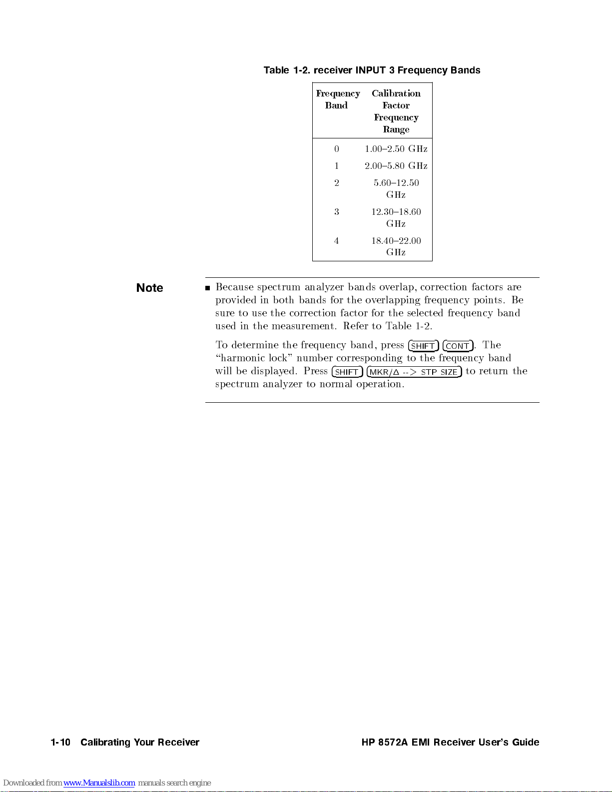
Table 1-2. receiver INPUT 3 Frequency Bands
Note
Frequency
Band
0 1.00{2.50 GHz
1 2.00{5.80 GHz
2 5.60{12.50
3 12.30{18.60
4 18.40{22.00
Because sp ectrum analyzer bands overlap, correction factors are
b
um
Press
normal
to
for
factor for
t. Refer
corresp
er
4
SHIFT
vided
pro
use
to
sure
used in
o
T
\harmonic
will
sp
the measuremen
determine the
displa
e
b
ectrum
oth
b
in
correction
the
k"
c
lo
ed.
y
analyzer
bands
frequency band,
n
the
5
op
Calibration
Factor
Frequency
Range
GHz
GHz
GHz
erlapping
v
o
the selected
able
T
to
press
onding
4
MKR/1
eration.
4
SHIFT
to
>
--
1-2
the
STP
frequency
frequency band
.
4
5
CONT
frequency
5
SIZE
to
p
.
5
ts.
oin
The
band
return
Be
the
1-10
Calibrating
Y
our
Receiv
er
HP
8572A
EMI
Receiv
er
User's
Guide
Page 23

Manual Measurements Using Receiver INPUT 3
1. Calibrate receiver INPUT 3. Refer to \Calibrating Receiver
INPUT 3".
2. Enter the reference level oset for manual calibration (from the
calibration table).
Note
For example, to enter029.2 dB press
4954.54254
displayed on the left side of the display.
3. Place the marker on the peak of the signal of interest and press
4
PRESEL PEAK
4. To determine the actual signal p ower level, subtract the correction
factor from the displayed amplitude reading (the correction factor
usually will be less than 7 dB).
5. For frequencies not given in the table, interpolate between table
values.
Because
the
guard
the
the
ou
y
elo
b
displa
Execute
frequency
when p
the actual
ed
y
displa
band.
calibration
correct
will
w
signal
not
test
the
ed amplitude.
y
4
PRESEL
erforming
5
. Notice that the correct reference level oset is
0
dBm
5
.
amplitude of
amplitude,
y
an
If
factor
amplitude.
to
need
limits,
PEAK
4.
band
measuremen
signals
from the
apply
ecause
b
5
ou
Y
the
the
for
must
are
eac
all
correction
v
o
ab
display
ou
y
If
correction
amplitude will
the
signal
h
select the
using
ts
4
SHIFT54REFERENCE LEVEL542
will
ys
a
factor
near the
signal
ed
the
factor
frequency
in
RF
receiv
alw
acts
test
lev
reference
to
b
preselector
INPUT
er
an
as
limit,
to
el
lev
signals
lo
e
band
signals
eor
use
w
lo
e
b
additional
subtract
determine
oset,
el
sev
than
er
w
through
1
ypass
b
3.
er
eral
than
dB
the
path
5
User's
HP
8572A
EMI
Receiv
er
Guide
Calibrating
Y
our
Receiv
er
1-11
Page 24
Automated Measurements Using Receiver INPUT 3
Note
To determine the corrected signal level, subtract the gain from the
measured signal amplitude.
Be sure to calibrate your receiver before making this measurement.
Follow all the amplitude accuracy considerations discusse in \When
to Calibrate Your Receiver" at the beginning of this chapter.
Calibration data is supplied on two disks, for HP 9000 Series 200/300
controllers using the HP BASIC programming language (see
8571A/8572A EMI Receiver 1 GHz to 22 GHz Calibration Data
Manual
same two les:
BDAT for use with op eration verication software.
Gain Table provided as ASCII data in CITIle data format. It
A
do
order
Be
analyzer
atten
). Both the single-sided and the double-sided disk contain the
Measuremen
EMI
later.
example
format
appropriate
dB
0
for
\Soft
cumen
HP
sure
uation.
olb
o
T
are
w
tation, and
n
part
the
use
to
uation
atten
e
b
can
are
w
Soft
x"
o
sample data
er
b
um
correction
setting;
the
y
b
used
Revision
with
disk con
85103-10002
taining utilities,
factor
data
les
.
is
85869A
HP
A.03.00 or
for
the
for
pro
CITIle
vided
HP
programs,
ailable;
v
a
is
ectrum
sp
10
and
t
dB
general
a
ou
y
e
giv
o
T
analyzer
the
Use
on
sho
plotted
is
also
graphic format
ectrum
sp
format.
actual signal amplitude.
view
display
the
correction
ws
atten
calibration
of
uation.
table,
receiv
as a
factors
Figure
er
20-p
sho
response,
mo
t
oin
b
for
is
1-2
in Figure
wn
ving
oth
an
calibration
the
erage.
v
a
dB
0
example
1-1,
data
This
dB
10
and
this
of
to determine
1-12
Calibrating
Y
our
Receiv
er
HP
8572A
EMI
Receiv
er
User's
Guide
Page 25
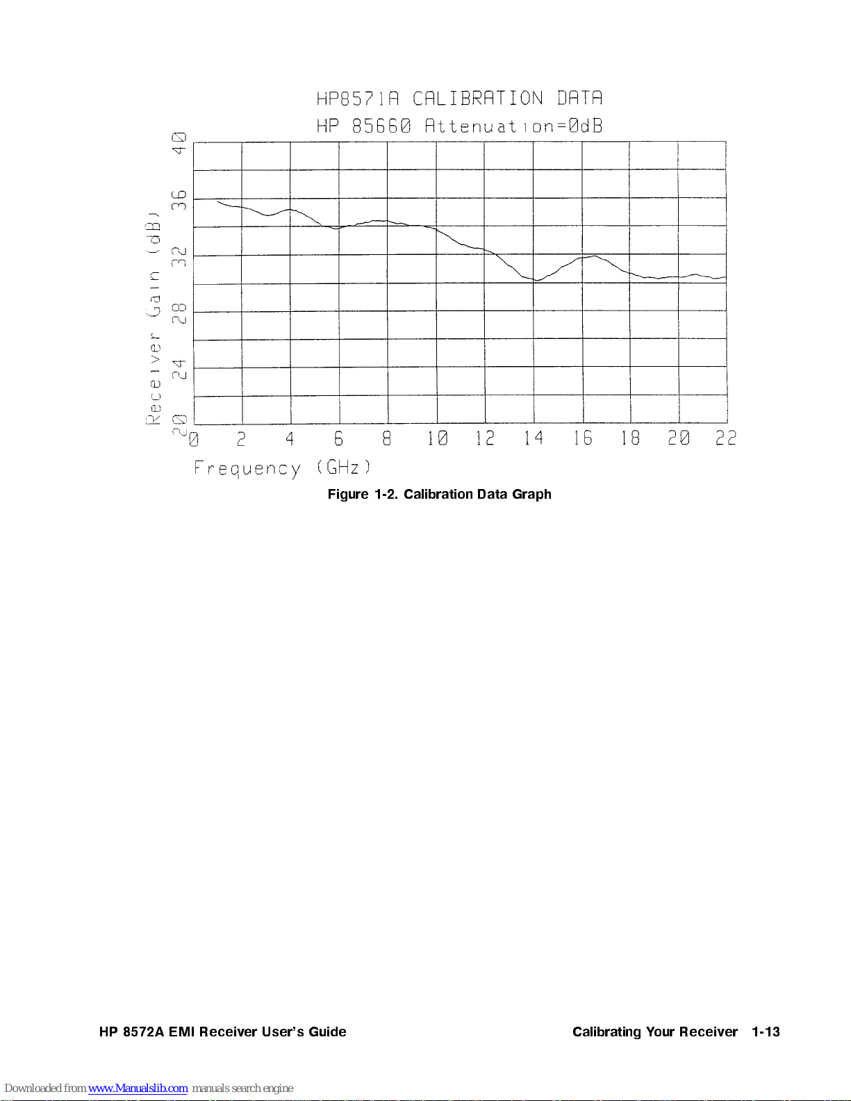
Figure
Calibration
1-2.
Data
Graph
User's
HP
8572A
EMI
Receiv
er
Guide
Calibrating
Y
our
Receiv
er
1-13
Page 26
Spectrum Analyzer Corrected Mode
Warning
Do not use the spectrum analyzer corrected mode with the HP 8572A
microwave EMI receiver.
When corrected mo de is on,
the display.To turn o corrected mode, press
The calibration pro cedures in this chapter ensure the specied
amplitude accuracy. There is no additional benet from using the
spectrum analyzer corrected mode.
CORR'D
appears on the lower left side of
4
SHIFT54STOP FREQ
5
.
1-14
Calibrating
Y
our
Receiv
er
HP
8572A
EMI
Receiv
er
User's
Guide
Page 27
Operation Verification
In this chapter, you will learn how to install the EMI receiver system
operation verication test software, and how to perform all required
and optional tests. The software is designed to provide a high level
of condence that the EMI receiver system meets its specications
without requiring excessive test equipment or test time.
Chapter 3, \Test Descriptions," describes each op eration verication
test in detail. Refer to that chapter for information regarding an
individual test.
Note
T
need
v
test
may
con
through
It
tests
erform
p
o
the
l
al
erication
equipmen
need to
enience,
v
y
ab
es
tak
the
for
the
test
w
soft
t.
mo
calibration
cal
lo
our
four
out
HP
range
full
equipmen
directly
are
ou
y
If
the
dify
Hewlett-P
hours
8572A
of
use
op
and
to
micro
eration
op
listed
t
supp
other mo
eration
erformance
p
ard
k
ac
complete
e
av
w
v
able
T
in
only
orts
dels of
erication
v
service
all
EMI
erication
The
.
2-1
recommended
the
equipmen
test
program.
erication
v
ter.
cen
eration
op
the
er.
receiv
tests,
op
are
will
ou
y
eration
ou
y
t,
our
y
or
F
ailable
v
a
erication
v
2
oard
eyb
in
the
the
in
(k
men
eration
op
safe
a
us
place.
and
devices
input
eral
sev
minor
the
disks;
orts
screen.
make
store
dierences
text
backup
the
copies of
kup
bac
disks
Because the
mouse),
eys
softk
Before
erication soft
v
an original disk is damaged, or if program data is altered or lost,
you will have this backup set. Operation verication software is
sold in complete sets only; you cannot order an individual disk.
program supp
ma
ou
y
displa
starting
notice
y
on
ed
y
the tests,
are
w
or
If
User's
HP
8572A
EMI
Receiv
er
Guide
Operation
erification
V
2-1
Page 28
Step 1. Set up the hardware for operation verification testing
Operation verication software runs on HP 9000 Series 300
computers. The computer must have:
A minimum of 2.5 to 4 megabytes of RAM, depending on the
computer's display conguration.
An HP-IB interface.
A 3.5 inch double-sided exible disk drive.
1. Connect the EMI receiver system to the computer connector.
If the computer has an HP 98624A HP-IB interface:
a. Connect your EMI receiver system to HP-IB SELECT
CODE 8.
b. Check that the address switch on the HP 98624A HP-IB
interface matches the HP-IB controller device address.
to
t
computer
0.5
a
cable,
vior
Peripher
terface:
in
mark
the
meter
similar
or
when
ed
Series
9000
HP
the
to
refer
lation
the
HP-IB
HP-IB
eled
lab
HP
(
disk
,
erication
v
computer
,
Guide,
es not
do
EMI
cables
CODE
of the
HP-IB
10833D
driv
olume
V
receiv
CODE
from
connector
7
external
SELECT
BNC
exhibit
es
tests.
the
and
1.
an
e
hav
er system
7.
the
0.5
unpredictable
disk
HP
to the
test
on
disk
CODE
meter
driv
necessary
If
c.
Instal
computer
the
If
Connect
a.
HP-IB SELECT
SELECT
cable
eration
op
on
the
the
the
Connect
2.
HP-IB
Connect
3.
connector
HP-IB
cable).
Occasionally
sharing the HP-IB with instruments. If this occurs, connect the
disk drive to a separate HP-IB interface.
4. Set the external test equipment and the EMI receiver system line
switches to ON. Allow the equipmenttowarm up as specied for
the
urn
T
5.
200/300
98624A
connector
equipmen
computer.
the
to
e
driv
using
,
7
HP-IB
b
e.
HP-IB
the
eha
al
erification
2-2
Operation
V
HP
8572A
EMI
Receiv
er
User's
Guide
Page 29
Step 2. Load the software
To run the operation verication test software, you must have
aversion of the BASIC programming language loaded on the
computer. You also will need several specic binaries (BIN les|see
below).
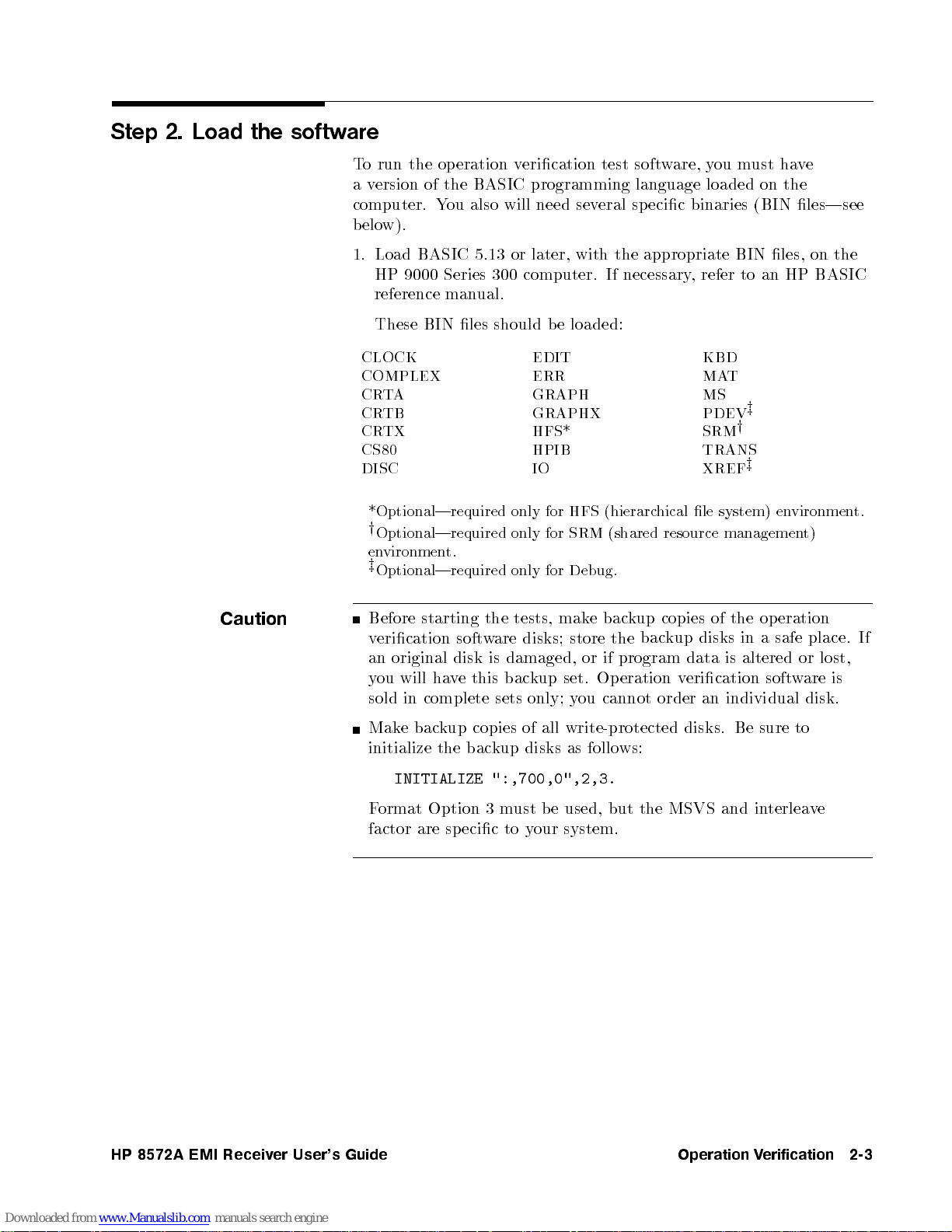
1. Load BASIC 5.13 or later, with the appropriate BIN les, on the
CLOCK EDIT KBD
COMPLEX ERR MAT
CRTA GRAPH MS
CRTB GRAPHX PDEV
CRTX HFS* SRM
CS80 HPIB TRANS
DISC
HP 9000 Series 300 computer. If necessary, refer to an HP BASIC
reference manual.
These BIN les should be loaded:
z
y
IO XREF
z
Caution
vironmen
the
in a
altered
en
eration
op
safe
or
w
soft
sure to
t)
place.
are
disk.
system)
le
kup
bac
the
program
eration
ws:
hical
resource
copies
kup
data
erication
v
order
disks. Be
managemen
of
disks
is
individual
an
*Optional|required
y
Optional|required
starting
will
complete
in
bac
e
t.
soft
disk
e
v
ha
kup
the bac
environmen
z
Optional|required only
Before
erication
v
original
an
ou
y
sold
Mak
initialize
INITIALIZE ":,700,0",2,3.
Format Option 3 must be used, but the MSVS and interleave
factor are specic to your system.
only
only
tests,
the
are
w
damaged, or
is
bac
this
sets
copies
kup disks
(shared
SRM
for
Debug.
for
bac
e
mak
store
disks;
if
Op
set.
kup
cannot
ou
y
only;
all write-protected
of
as follo
(hierarc
HFS
for
t.
If
lost,
is
User's
HP
8572A
EMI
Receiv
er
Guide
Operation
erification
V
2-3
Page 30
Assign the MASS STORAGE IS (MSI) to the driveyou will use as
the default drive.
For example:
MSI ":,700,0"
Insert disk 1 into the disk drive.
Type
When prompted, remove disk 1 from the disk drive and insert disk
2.
Press
LOAD "OPV",1
4
CONTINUE
5
.
and press
4
ENTER
5
.
erification
2-4
Operation
V
HP
8572A
EMI
Receiv
er
User's
Guide
Page 31

Step 3. Select the EMI receiver system model
Note
The Test Executive Program will guide you through the steps to
set up your system for the operations verication tests.
The EMI op eration verication software provides op eration
verication tests for the HP 8572A microwave EMI receiver. If your
EMI receiver system is an Option 049, you will enter this information
when you perform
information".
4
1.
2.
3.
Use
Press
page
o
T
+
con
5
4
ENTER
for
tin
and
the
ue,
\Step 4. Enter the EMI receiver system test
d a
=== SPECIFIC MODEL? ===
HP8571A
NNNNNNNNNNNNNNNNNNNNNNN
HP8572A
c b
NN
NN
NN
NN
N
N
N
N
N
N
N
N
N
N
N
N
N
N
N
N
N
N
the
er
ey
k
y
t
8572A
HP
UUT. The
system
on
op
the
computer
.
computer will
erication
eration
v
except
displa
4
P
4
5
*
to
5
EMI
press
highligh
to
select
receiv
an
A
test.
USE
title
a
y
.
5
User's
HP
8572A
EMI
Receiv
er
Guide
Operation
erification
V
2-5
Page 32

Step 4. Enter the EMI receiver system test information
Tomake sure test records are as complete as possible, and that the
correct tests are p erformed, you will need to enter information about
the EMI receiver system.
d a
============UUT: HP8572A============
NNNNNNNNNNNNNNNNNNNNNNNNNNNNNNNNNNNNNNNNNNNNNNNNNN
SERIAL NUMBER
ADDRESS TYPE HP-IB
ADDRESS 718
CONTROLLER
OPTIONS
TEMPERATURE 23.0 DEG C
HUMIDITY 50.0 %
LINE FREQUENCY 60 Hz
c b
N
N
N
N
N
N
NN
NN
NN
NN
N
N
N
N
N
N
N
N
N
N
N
N
N
N
N
N
N
NN
1.
2.
Use
yp
T
EMI
4
5
*
the
e
receiv
4
and
+
complete
er
to
5
system
select
ten-digit
press
;
N
SERIAL
serial
4
ENTER
NUMBER
um
n
.
5
N
N
N
N
N
N
N
.
for
er
b
Press
y
our
4
ENTER
.
5
Note
hanged,
ec
b
to
need
list
this
in
items
other
If
3.
instructions:
hapter)
c
end of
the
8572A
will
for
(at
see
Assigning
Selecting
Adding
micro
the
this
w
message
sections
\Optional:
\Optional:
\Optional:
\Optional: Mo
\Optional: Modifying the humidity setting"
\Optional: Selecting the line frequency"
You do not need to change the
HP
you
needed
procedure.
4. When the test information is correct, press
this
the
the
option
difying the
EMI
e
v
a
It
Press
.
UUT
address
EMI
049"
temperature
receiv
seems
4
RETURN
for
e"
yp
t
system
er
receiv
NNNNNNNNNNNNNNNNNNNNNNNNNNNNNNNN
CONTROLLER
you
If
er.
a
that
con
to
5
to
refer
address"
setting"
setting for the
NNNNNNNNNNNNNNNNNNNNNNNNNNNNNNNN
select
controller
CONTROLLER
with
ue
tin
4
CONTINUE
these
not
is
the setup
5
.
,
erification
2-6
Operation
V
HP
8572A
EMI
Receiv
er
User's
Guide
Page 33

Step 5. Choose the output destination for your test results
Reports of test results maybe printed on the computer's printer,
displayed on the computer's display, or not displayed. You must
choose where you want to direct these rep orts.
d a
Where should test reports be directed?
c b
1. Use
2. Press
4+5
and
4*5
to select if you want the test reports displayed on
the computer display(CRT), printed on the printer, or not output
at all.
4
ENTER
5
.
NNNNNNNNNNN
CRT
PRINTER
NO OUTPUT
User's
HP
8572A
EMI
Receiv
er
Guide
Operation
erification
V
2-7
Page 34

Step 6. Select \Test all model numbers"
You must enter information for all equipmentusedinyour
EMI receiver system before performing any operation verication
test.
d a
============UUT: Selection============
NNNNNNNNNNNNNNNNNNNNNNNNNNNNNNNNNNNNNNNNNNNNNNNNNNNNNNNNNNNNNNNNNNNN
Test all model numbers
Test only the mainframe/base unit
c b
1. Select
Test only the mainframe/base unit
EMI receiver system.
Press
2.
NNNNNNNNNNNNNNNNNNNNNNNNNNNNNNNNNNNNNNNNNNNNNNNNNNNNNNNNNNNNNNNNNNNN
Test all model numbers
4
ENTER
.
5
.
does not apply to the
erification
2-8
Operation
V
HP
8572A
EMI
Receiv
er
User's
Guide
Page 35

Step 7. Select equipment from the UUT Configuration menu
After you select
menu, you will see a display similar to this:
d a
c b
NNNNNNNNNNNNNNNNNNNNNNNNNNNNNNNNNNNNNNNNNNNNNNNNNNNNNNNNNNNNNNNNNNNN
Test all model numbers
==========UUT: Configuration==========
NNNNNNNNNNNNNNNNNNNNNNNNNNNNNNNNNNNNNNNNNNNNNNNNNNNNNNNNNNN
BASE UNIT HP8572A
UUT RF HP85660B
UUT IF HP85662A
UUT SW HP11713A
UUT AMP HP8449B(H02)
from the UUT Selection
1. Use
2.
4*5
and
4+5
Conguration menu.
4
Press
ENTER
5
to select a piece of equipment from the UUT
.
User's
HP
8572A
EMI
Receiv
er
Guide
Operation
erification
V
2-9
Page 36

Step 8. Assign serial numbers to all equipment
Before you can begin performance verication testing, you must
enter a serial number for each piece of equipment on the UUT
Conguration menu. At this menu, you also will identify address
type, address, and any options for each piece of equipmentinthe
receiver under test.
d a
==========UUT: Configuration==========
MODEL NUMBER HP8572A
NNNNNNNNNNNNNNNNNNNNNNNNNNNNNNNNNNNNNNNNN
SERIAL NUMBER
ADDR TYPE HP-IB
ADDRESS 718
OPTIONS
c b
N
N
N
NN
NN
1.
Use
4
+
5
and
4
to
5
*
select
N
SERIAL
N
N
N
N
N
N
N
N
N
N
NN
NN
NN
N
N
N
N
N
N
NUMBER
N
N
N
N
N
N
N
N
N
N
N
.
2.
3.
4.
5.
6. When all the conguration information is correct, press
4
Press
En
Select
Press
If
4*5
(at
4
ENTER
the
ter
equipmen
4
ENTER
need
ou
y
and
the
\Optional:
\Optional:
\Optional: Adding option 049"
CONTINUE
4
+
end
serial
to
to
5
of this
5
.
5
5
.
b
um
n
from
t
.
hange
c
the
select
chapter)
Assigning
Selecting
of
er
the
other
item
the
the
the
EMI
instrument
Conguration men
UUT
conguration
er
receiv
hanged;
c
e
b
to
instructions:
for
yp
address
t
receiv
er
you
e"
system
selected
on
refer to
address"
u".
this
these
in
\Step
use
list,
sections
7.
erification
2-10
Operation
V
HP
8572A
EMI
Receiv
er
User's
Guide
Page 37

Step 9. Verify the test equipment
Note
The Test Executive Program will take a few moments to checkthe
equipment for the tests that need to be p erformed.
d a
EQUIPMENT USED (MODEL/ADDRESS):
HP436A 713
HP8481D
HP8482A
HP8161A 712
HP83830A 716
HP3335A 704
HP5316A 720
c b
um
n
del
mo
the
that
erify
V
1.
testing.
equipmen
If
2.
matc
N
N
N
N
N
CONTINUE
op
displa
the
y
h
N
N
N
N
N
N
N
N
N
N
N
NN
N
eration
a
t
y
test
our
N
N
N
N
N
N
N
and
,
erication
v
ailable
v
ed
for
test equipmen
equipmen
4
press
ENTER
tests".
ers
b
mo
t
5
NNNNNNNNNNNNNNNNNNNNNNNNNN
CONTINUE
PRINT
and
del
mo
t
n
del
on
Go
.
addresses
b
um
n
ers
b
um
\Step
to
matc
ers
and
11.
the
h
addresses
and
addresses,
Run
select
the
equipmen
test
ed
y
displa
the
If
3.
test equipmen
your
h
matc
not
do
addresses, or
equipmen
alternate equipmentyou are using:
Tochange your test equipment and its addresses to matchthe
displayed test equipment and addresses:
Toc
matchy
tand
Make the equipmentchanges to match the displayed models.
N
N
N
N
NN
N
N
N
N
N
N
N
N
N
N
N
NN
N
N
N
N
N
N
Select
Press
Go on to
Refer to \Optional: Changing the default equipment" at the
end of this chapter.
T
supp
eac
N
CONTINUE
4
hange the displa
our test equipmen
able
orted
instrumen
h
5
ENTER
2-1
.
\Step 11. Run the operation v
that
in
equipmen
test
t
on
yed list of test equipmen
section
ma
t
ou
y
displa
the
t:
lists
t.
substitute
y
t, y
m
default
Only
ust
.
y
ou m
edit
listed
for
hange
c
ust
displa
the
erication tests".
t and addresses to
alternate
and
alternate
default
the
y
mo
mo
and addresses
bers
um
n
del
mo
our
y
the
to
mo
dels
del n
test
dels
um
of
of
er.
b
User's
HP
8572A
EMI
Receiv
er
Guide
Operation
erification
V
2-11
Page 38

Step 10. Confirm the list of accessories
The screen will display a list of accessories used with the
EMI receiver system for the op eration verication tests.
d a
=============== ACCESSORIES USED ===============
Semirigid coax cable type N (m) to N (m) HP 85685-20005
122 cm flexible coax cable BNC (m) to BNC (m) HP 10503A (3 required)
Flexible coax calibration cable type N (m) to N (m) HP 8120-4781
Adapter type N (m) to BNC (f) HP 1250-1535
91 cm flexible coax cable type N (m) to N (m) HP 8120-5140
NNNNNNNNNNNNNNNNNNNNNNNNNN
CONTINUE
PRINT
c b
N
N
N
N
N
NN
NN
NN
NN
N
N
N
Select
N
N
PRINT
N
N
N
NN
NN
N
N
N
N
N
N
N
N
N
N
N
CONTINUE
N
to go
on
to
the
next
step
of
the
setup
accessory
this
of
y
cop
a
t
an
w
ou
y
if
N
N
N
N
N
N
list.
pro
Select
cedure.
erification
2-12
Operation
V
HP
8572A
EMI
Receiv
er
User's
Guide
Page 39

Step 11. Run the operation verification tests
d a
============== TEST LIST ==============
Calibrator Amplitude Accuracy
Log Fidelity
Linear Fidelity
Reference Level Switching Uncertainty
Receiver Calibration Input 1
Amplitude Accy. Input 1 (10 dB AT)
Amplitude Accy. Input 1 (10 dB AT), 20 Hz-9 kHz
Amplitude Accy. Input 1 (0 dB AT)
Amplitude Accy. Input 1 (0 dB AT), 20 Hz-9 kHz
Disp. Average Noise Input 1, 10 Hz RBW
Sensitivity Input 1, 20 Hz to 9 kHz
Residual Responses Input 1
Bandwidth
Calibration
Pulse
Amplitude
Amplitude
Disp.
Residual
Amplitude
Disp.
Residual
c b
Accuracy
Input 2
Response
Accy.
Accy.
Average
Responses
Accy.
Average
Responses
Input
Input
Noise
Input
Noise Input
2
2(0
Input
Input
3
Input
(10
2
3
dB
dB AT)
2
10
3,
AT)
Hz
RBW
tests
er
receiv
EMI
e
v
a
w
operation
egin
b
instructions
micro
erication
v
4*5
and
running
5
the
til all op eration
.
screen
tests.
4+5
to view the entire list. These
test.
up
set
to
The
equipmen
test
the
verication tests are
ma
t.
y
8572A
HP
ws the
4+5
ollow
ysho
and
4
ENTER
the
4*5
to select the rst test.
to
5
on-screen
4
CONTINUE
The displa
not show all the tests; use
operation verication tests are organized in a specic sequence,
designed to minimize changes in equipment setups.
1. Use
Press
2.
F
3.
Chapter 3 has illustrations of test setups and individual test
descriptions.
4. Repeat steps 1, 2, and 3 un
completed.
5. When you have completed the tests, or when you wanttoexitthe
program, press
User's
HP
8572A
EMI
Receiv
er
Guide
Operation
erification
V
2-13
Page 40

d a
Quit the Test Executive Program?
c b
NNNNNNNNNNN
YES
NO
6. Use the arrow keys to select
7. Press
4
ENTER
5
.
YESorNO
.
erification
2-14
Operation
V
HP
8572A
EMI
Receiv
er
User's
Guide
Page 41

Optional: Installing the software on an SRM or HFS hard disk
The operation verication software may be installed on a shared
resource manager (SRM) or hierarchical le structure (HFS) hard
disk system. For information about creating directories and copying
les, refer to the appropriate SRM or HFS hard disk manual.
To install the test software:
1. Create a directory to contain the operation verication program
and its asso ciated les.
2. Copy all operation verication program les from the two 3.5 inch
disks to this directory.
User's
HP
8572A
EMI
Receiv
er
Guide
Operation
erification
V
2-15
Page 42

Optional: Assigning the address type
d a
============ UUT: HP8572A ============
SERIAL NUMBER 0000A00000
NNNNNNNNNNNNNNNNNNNNNNNNNNNNNNNNNNNNNNNNNNNNNNNNNN
ADDRESS TYPE HP-IB
ADDRESS 718
CONTROLLER
OPTIONS
TEMPERATURE 23.0 DEG C
HUMIDITY 50.0 %
LINE FREQUENCY 60 Hz
c b
e options.
4
Press
1.
can
the
Use
2.
Press
3.
4. V
address information needs to be updated, refer to the follo
section,
When
5.
If the
4.
ENTER
select
default.
d a
c b
4
5
+
4
ENTER
erify that
NNNNNNNNNNNNN
ADDRESS TYPE
NNNNNNNNNNNNNNNNNNNNNNN
ADDRESS
ter
En
.
5
HP-IB,
============
SERIAL NUMBER
NN
N
N
N
N
N
N
N
N
ADDRESS
N
N
N
N
N
HP-IB
NONE
OTHER
TEMPERATURE
HUMIDITY 50.0 %
LINE FREQUENCY 60 Hz
4
and
*
.
5
the EMI receiv
\Optional: Selecting the EMI
NNNNNNNNNNNNNNNNNNNNNNNNN
EMI
the
displa
The
NONE,
N
N
N
N
N
N
N
N
N
N
N
N
N
N
N
N
N
N
N
N
N
TYPE
N
N
N
N
N
N
N
N
N
N
N
N
select
to
5
information is correct, continue to step 3 of
receiv
OTHER
or
UUT:
0000A00000
N
N
N
NN
N
N
HP-IB
23.0
address
the
er system address is correct. If the
is selected, the address selection is reset.
system
er
the address
as
HP8572A
DEG
typ
test
address
oer
will
y
typ
yp
t
============
C
e.
receiver system address".
information".
e.
You
HP-IB
wing
\Step
is
erification
2-16
Operation
V
HP
8572A
EMI
Receiv
er
User's
Guide
Page 43

Optional: Selecting the EMI receiver system address
The EMI receiver system factory-preset address is 718. If your
receiver is set to an address other than 718, you maychange this
software to op erate using your EMI receiver system's current address.
d a
============UUT: HP8572A============
SERIAL NUMBER 0000A00000
ADDRESS TYPE HP-IB
NNNNNNNNNNNNNNNNNNNNNNNNNNNNNNNNNNNNNNNNNNNNNNN
ADDRESS 718
CONTROLLER
OPTIONS
TEMPERATURE 23.0 DEG C
HUMIDITY 50.0 %
LINE FREQUENCY 60 Hz
c b
N
NN
N
N
N
N
N
N
N
N
N
N
N
N
N
N
N
N
N
NN
1.
Select
EMI
N
ADDRESS
receiv
system
er
,
then
press
718.
is
4
ENTER
.
5
The
default
address
for
the
the
Use
2.
Use
digit.
Use
Press
3.
Return
4.
information"
arro
4
(
4
5
+
4
ENTER
to
5
and
step
w
and
5
eys
k
4
)
4
5
*
.
3of
to con
hange
c
to
mo
to
5
hange
c
to
\Step 4.
ue.
tin
er
address.
address
digit.
system
test
the correct
yto
displa
the
um
b
the
to the
er
EMI
cursor
the
e
v
n
the
ter
En
to
the
receiv
appropriate
correct
User's
HP
8572A
EMI
Receiv
er
Guide
Operation
erification
V
2-17
Page 44

Optional: Adding option 049
If you have an Option 049 EMI receiver system, enter the option
information to ensure that your EMI receiver system is tested
completely.
Select
1.
option
d a
============UUT:
SERIAL
ADDRESS
ADDRESS
CONTROLLER
N
N
N
N
N
N
OPTIONS
==========UUT
N
N
N
N
N
N
049
NUMBER
TYPE
N
N
N
N
N
N
N
N
N
N
N
N
N
N
N
N
N
N
N
N
NN
NN
N
N
N
N
N
N
N
N
N
N
N
N
N
N
N
N
N
NN
NN
NN
NN
N
N
N
N
N
N
N
N
N
Deletes the
NO
HP8572A============
0000A00000
HP-IB
718
N
N
N
N
NN
NN
N
OPTIONS===========
N
N
N
N
N
N
N
N
NN
NN
NN
NN
N
N
N
N
N
d a
============UUT: HP8572A============
SERIAL NUMBER 0000A00000
ADDRESS TYPE HP-IB
ADDRESS 718
CONTROLLER
NNNNNNNNNNNNNNNNNNNNNNNNNNNNNNNNNNNNNNNNNNNN
OPTIONS
TEMPERATURE 23.0 DEG C
HUMIDITY 50.0 %
LINE FREQUENCY 60 Hz
c b
N
NN
N
N
N
N
N
N
N
N
N
N
N
N
N
N
N
N
N
NN
NN
N
N
N
N
N
N
N
N
N
N
OPTIONS
selections.
N
N
N
N
N
N
N
N
N
N
N
N
N
N
NN
NN
NN
HP 8449B
,
NN
N
N
N
then
N
N
N
N
N
NN
NN
NN
in HP
N
N
N
4
press
NN
NN
NN
NN
N
N
N
N
N
N
N
N
N
8571A/HP 8572A
ENTER
N
N
N
N
N
N
N
N
N
N
5
N
N
N
N
N
N
N
.
NN
The
NN
NN
N
N
N
N
N
NN
screen
NN
N
N
N
N
N
N
N
N
N
N
N
N
systems
displa
will
N
N
N
N
N
NN
NN
NN
the
y
LINE FREQUENCY 60 Hz
c b
2.
3. Press
4. Return to step 3 of
erification
2-18
Operation
V
Press
4
ENTER
N
N
N
N
N
N
N
N
toggles
The HP 8449B Opt H02 preselector is deleted from y
receiver system conguration.
information"
NN
YES
4
CONTINUE
hange
to c
5
N
k
bac
5
.
to continue.
NNNNNNNN
N
N
N
N
N
N
NN
to
.
NO
\Step 4. En
NO
NNNNNNNNNNN
to
. (Pressing
YES
ter the EMI receiv
HP
8572A
EMI
4
ENTER
er system test
Receiv
again
5
our EMI
User's
er
Guide
Page 45

Optional: Modifying the temperature setting
You mayenter the ambient room temperature in which the
EMI receiver system is operating. This temp erature b ecomes part of
the test record.
d a
============= UUT: HP8572A ============
SERIAL NUMBER 0000A00000
ADDRESS TYPE HP-IB
ADDRESS 718
CONTROLLER
OPTIONS
NNNNNNNNNNNNNNNNNNNNNNNNNNNNNNNNNNNNNNNNNNNNNNN
TEMPERATURE 23.0 DEG C
HUMIDITY 50.0 %
LINE FREQUENCY 60 Hz
c b
Press
1.
ter temp
En
the
Use
2.
Use
Use
Press
3.
Return to
4.
information"
4
ENTER
arro
4
(
4
5
+
4
ENTER
.
5
eratures
w
and
5
and
.
5
step
to
The
eys
k
4
)
4
*
3
con
5
to
5
of
default
celsius
in
hange
c
to
mo
to
hange
c
\Step
ue.
tin
temperature
.
only
the
to
cursor
the
e
v
the correct
to
ter
En
4.
correct
the
is 23.0
the
to
temp
EMI
degrees celsius.
erature.
temp
b
to
digit
erature.
system
er
receiv
hanged.
ec
test
User's
HP
8572A
EMI
Receiv
er
Guide
Operation
erification
V
2-19
Page 46

Optional: Modifying the humidity setting
You may record the humidity of the area where the
EMI receiver system is operating. This humidity setting b ecomes
part of the test record.
d a
============ UUT: HP8572A ============
SERIAL NUMBER 0000A00000
ADDRESS TYPE HP-IB
ADDRESS 718
CONTROLLER
OPTIONS
TEMPERATURE 23.0 DEG C
NNNNNNNNNNNNNNNNNNNNNNNNNNNNNNNNNNNNNNNNNNNNNNN
HUMIDITY 50.0 %
LINE FREQUENCY 60 Hz
c b
NN
NN
NN
N
N
N
N
N
N
N
N
N
N
N
N
N
N
N
N
N
NN
ercen
the
N
HUMIDITY
t.
w
arro
k
,
eys
then
1.
2.
Select
p
Use
to
press
hange
c
4
ENTER
to
the
The
.
5
correct
default
umidit
h
umidit
h
.
y
y
is 50
Use
hanged.
c
Use
Press
3.
Return
4.
information"
4
(
4
5
+
4
ENTER
to
and
5
and
step
e
b
num
er
to
er.
b
system
test
column
the
the
to
to
the
EMI
correct
receiv
4
5
)
4
to
5
*
.
5
of
3
tin
con
to
mo
to
hange
c
\Step
ue.
v
digit
the
ter
En
4.
cursor
the
e
erification
2-20
Operation
V
HP
8572A
EMI
Receiv
er
User's
Guide
Page 47

Optional: Selecting the line frequency
You may record the line frequency the EMI receiver system is using
to operate. This line frequency setting becomes part of the test
record.
d a
============ UUT: HP8572A ============
SERIAL NUMBER 0000A00000
ADDRESS TYPE HP-IB
ADDRESS 718
CONTROLLER
OPTIONS
TEMPERATURE 23.0 DEG C
HUMIDITY 50.0 %
NNNNNNNNNNNNNNNNNNNNNNNNNNNNNNNNNNNNNNNNNNNNNNN
LINE FREQUENCY 60 Hz
c b
N
N
N
N
N
N
N
N
N
N
N
N
N
N
NN
NN
NN
NN
1.
Select
N
FREQUENCY
LINE
d a
N
,
then
press
4
ENTER
.
5
N
N
N
N
N
N
N
N
N
N
NN
NN
NN
NN
N
N
============
SERIAL
ADDRESS
ADDRESS
CONTROLLER
OPTIONS
TEMPERATURE
HUMIDITY
N
c b
arro
the
Use
2.
EMI receiv
Hertz.
3. Press
4. Return to step 3 of
information"
er system is using. The default line frequency is 60
4
ENTER
N
N
N
N
NN
NN
NN
NN
N
N
N
N
FREQUENCY
LINE
NNNNNNNNNNNNNNNNN
60 Hz
50 Hz
400 Hz
keys
w
5
.
to continue.
HP8572A
UUT:
N
N
N
NN
NN
NN
NN
0000A00000
HP-IB
718
23.0
50.0 %
N
N
N
N
N
N
Hz
60
line
the
NUMBER
TYPE
N
N
N
N
N
N
N
N
N
N
N
N
N
select
to
\Step 4. Enter the EMI receiver system test
============
C
DEG
frequency
that
the
User's
HP
8572A
EMI
Receiv
er
Guide
Operation
erification
V
2-21
Page 48

Optional: Changing the default equipment
If your test equipmentmodelnumbers and addresses are dierent
from the default test equipment (displayed when you veried the test
equipment), you must change the settings. Refer to
the test equipment"
only the equipment listed in Table 2-1. You must have BASIC 5.13
or later, with the appropriate binaries (BIN les) installed, to change
these default settings.
The TSCRIPT le contains the default test equipmentmodel
numbers and addresses. In this pro cedure, you will edit, save, and
run the TSCRIPT le.
Print the default equipmentlist
If you have a printer connected to your computer, you can printthe
default test equipment list. To print the list:
1.
Use
4
and
5
+
. This op eration verication software supports
4
select
to
5
*
NNNNNNNNNNNNNNNNN
PRINT
on
the
displa
\Step 9. Verify
.
y
2.
Exit
3.
4.
5.
6.
Load the
7. Insert op eration verication disk 1 in the default disk drive.
8. Type
9.
Edit the
10. Scroll to
4
Press
Use
Press
Press
Executive
The default
v
key). Wait for the asterisk in the lower right p ortion of the
computer display to disappear.
T
appear
TSCRIPT le sho
variable names with corresp onding descriptions are sho
Table 2-2.
ENTER
op
the
4
5
+
4
ENTER
4
CONTINUE
erication
default
GET "TSCRIPT"
EDIT
e
yp
default test equipmen
.
5
NN
N
N
N
CONTINUE
the
y
will
YES
are.
and press
4
RETURN
displa
t list
soft
N
N
N
N
N
N
NN
op
e
b
Press
.
(TSCRIPT)
t
erication
eration
and
on
v
4
5
Program.
selection is
test
the
CALIBRATION_STANDARDS(
select
to
5
*
displa
to
ou
Y
.
5
w
soft
equipmen
test
press
and
computer
ws the default list of test equipmen
are
w
N
N
N
N
N
N
N
N
N
N
N
N
N
on
eration
if
asked
4
ENTER
4
RETURN
ait
W
.
5
.
y
. This section of the
displa
the
erication
v
w
ou
y
to exit
5
le
5
(or the equivalent
the
for
.
y
test
to
t
an
the op
TSCRIPT
men
quit
t. The
wn in
u.
T
the
eration
le to
est
erification
2-22
Operation
V
Table 2-1
op
the
all
receiv
EMI
group
h
eac
lists the supported test equipmentyou need to p erform
e
v
a
eration
The equipmen
er.
equipmen
of
erication
v
t
tests
is
t
separated
is
HP
on
group
8572A
HP
the
according
ed
a
y
b
EMI
8572A micro
horizon
Receiv
tal
er
to
w
function;
line.
User's
t
A
Guide
Page 49

least one piece of test equipmentmust b e selected from each
group.
Table 2-1. Test Equipment
Default Test Equipment Model Number Default
Address
* Power meter HP 436A p ower meter 713
Power meter HP 437B p ower meter 713
Power meter HP 438A dual-channel
power meter
* Power sensor HP 8481D N(m) power
sensor
* Power sensor HP 8482A N(m) power
sensor
* Power sensor HP 8484A N(m) power
sensor
Power sensor HP 8485D APC-3.5 mm(m)
sensor
er
w
o
p
generator
Pulse
* Pulse
* Syn
* Synthesizer/Level
* Univ
* This is the factory-set default test instrumen
verication soft
changed to an
generator
Pulse/F
generator
sw
Syn
sw
Syn
sw
Syn
sweeper
Synthesized
sweeper
generator
Univ
unction
thesized
eeper
thesized
er
eep
thesized
er
eep
thesized
ter
coun
ersal
ter
coun
ersal
ware iden
y supported equipmen
ties. This default instrumen
8160A
HP
pulse
8161A
HP
pulse
8116A
HP
generator
83630A syn
HP
eeper
sw
83640A
HP
eep
sw
83650A
HP
eep
sw
8340A
HP
sweeper
HP 8340B synthesized
sweeper
HP 3335A synthesizer/level
generator
5316A
HP
5316B
HP
programmable
generator
programmable
generator
pulse/function
1
syn
1
er
syn
1
er
syn
univ
univ
wn in this table.
t sho
thesized
thesized
thesized
thesized
2
ter
coun
ersal
2
ter
coun
ersal
t that the operation
ybe
tma
713
None
None
None
None
712
712
712
716
716
716
716
716
704
720
720
User's
HP
8572A
EMI
Receiv
er
1
When using an HP 8360
under
Adrs Menu Programming Language
communicate over the HP-IB.
instrument
this
need
ou
Y
2
Guide
Series synthesized sw
if
only
, for the op eration verication software to
using
are
ou
y
eeper, y
HP
an
ust select
ou m
pulse/function
8116A
Operation
Analyzr
erification
V
generator.
2-23
Page 50

Table 2-2. Test Equipment Variable Names
Variable Name Description
PM1 power meter 1
FC1 frequency counter 1
RFPS RF power sensor
LRFPS lowRFpower sensor
LG1 level generator
SYN1 synthesized source
FG1 function generator 1
11. Edit the default list of test equipment as needed. Table 2-2 gives
the variable names for test instruments. Use this to identify the
equipment defaults you wanttochange.
For example, to substitute the HP 436A power meter for the
HP 438A dual-channel power meter:
Note
Scroll
P
b
438A
o substitute
T
HP
an
FG1(HP8161A)
FG1(HP8116A)
e
b
Then
this
(commen
Counter"(FC1)
12. Scroll to the
equipment addresses as you did in step 2 of this procedure.
Valid addresses are 00 to 30. Valid select codes are 0 through 5,
and 7
equipmen
(UUT).
to
cursor
osition
e
scroll
line,
the
PM1(HP438A)
.
a
8161A programmable
to
"Universal
nd
haracter). Delete
tc
through
addresses
t
.
8116A
HP
and
line
.
S_PULSE1("Power
the
line.
DEFAULT_ADDRESSES(
The
9.
under
Notice
yp
t
default
to
PM1(HP436A)
the
line.
and
6
the
no space
is
there
pulse/function
generator,
pulse
er
v
8116A
e
Counter"(FC1)
y addresses
an
o
Meter"(PM1)
the asterisk
section of the le and edit the
select
co
8
e
yp
t
generator
scroll
8161A
and
the
in
7.
is
de
b
used
.The
bet
.
y
result should
een
w
for
the
to
result
The
line.
the
note
"Universal
not set
Do
unit
the
HP
and
should
Under
asterisk
the
under
test
Save the test equipmen
verication softw
13.
14.
erification
2-24
Operation
V
t list edits and restart the operation&
are
RE-SAVE "TSCRIPT"
ype
and
ortion
p
HP
ey), t
ear.
press
8572A
of
4
Return
computer
the
EMI
W
.
5
Receiv
ait
for
screen
User's
er
the
to
Guide
Press
4
(or the equiv
5
Stop
, and press
TSCRIPT le. Wait for the asterisk in the lower right p ortion of
computer
the
e
yp
T
asterisk
disapp
4
Return
"C_TSCRIPT"
LOAD
the
in
ear.
5
screen
er
w
lo
alentk
(or the equivalentkey) to save the edited
disapp
to
t
righ
Page 51

15. Type
CONVERSION COMPLETED
operation verication software is ready to load and run.
16. Continue at the b eginning of the operation verication software.
Refer to
RUN
and press
\Step 3. Select the EMI receiver system model".
4
5
. When the message
Return
appears on the computer screen, the
TEST SCRIPT
User's
HP
8572A
EMI
Receiv
er
Guide
Operation
erification
V
2-25
Page 52

Optional: Entering power sensor calibration factors
The operation verication test program requires calibration factors
for the p ower sensor. If the le containing calibration factors is in the
default drive, the program will retrieve these factors automatically.
If this program is not able to nd calibration factors for the power
sensor b eing used, a prompt appears on the computer display:
d a
CAL FACTOR file for HP8485D (XXXX) was not found
c b
If there is a calibration factor le for your power sensor, select
CHANGE DISK
taining
con
ou
y
If
Align
1.
the
. The program will prompt you to insert the disk
to the
calibration
not
e
v
ha
the selection
alen
equiv
factors
created a
ey).
k
t
window
in
calibration factor
CREATE
er
v
o
NNNNNNNNNNNNNNNNNNNNNNNNNNNNNNNNNNN
CREATE FILE
CHANGE DISK
ABORT
default driv
le for
FILE
e.
your
and
o
p
press
w
er
4
Select
sensor:
(or
5
d a
FACTOR
HP8485D (ID=XXXX)
---------------------------------------------------------
c b
CAL
N
N
NN
NN
N
N
N
N
N
N
N
N
N
EDIT
EDIT
EDIT
2. Highlight
(or the equivalentkey).
ter
En
3.
Use
eld.
4. Press
calibration factor.
5. Highlight
frequencies with corresp
computer screen.
Align
6.
that
EDIT REFERENCE CAL FACTOR 100.00%
REF CAL
the
4
(
Then,
4
Return
the
needs
4
and
5
EDIT CAL FACTORS
windo
5
)
4
use
5
(or the equiv
w
editing,
N
N
N
N
N
N
NN
NN
N
N
N
N
N
N
N
N
N
N
N
N
N
N
N
N
N
N
N
REFERENCE
CAL FACTORS
FREQUENCY
CTOR
A
F
osition
p
to
4
and
*
5
ver
o
then
5
+
alentk
onding calibration factors appear on the
frequency
the
press
NN
NN
N
N
N
N
N
N
N
N
N
N
N
N
N
N
N
FACTOR
CAL
LIST
prin
cursor
the
hange the
c
to
ey) to en
and press
4
5
Select
NN
N
N
N
N
N
N
N
N
N
N
N
N
N
N
N
N
N
N
N
N
N
100.00%
our
y
on
ted
under
alue.
v
ter the reference
4
5
Select
the
with
.
---
N
N
N
N
N
N
N
N
N
N
N
N
NN
and press
er sensor.
w
o
p
appropriate
the
. The list of
calibration
4
Select
factor
5
erification
2-26
Operation
V
7.
Use
eld.
4
(
Then,
5
and
4
)
use
5
4
*
to p
and
5
osition
4
5
+
to
HP
the
c
cursor
hange
8572A
under
the
EMI
alue.
v
Receiv
appropriate
the
er
User's
Guide
Page 53

8. Press
9. Repeat steps 6 through 8 until all calibration factors are entered.
4
Return
5
(or equivalentkey) to enter the calibration factor.
Note
10. Press
11. Highlight
12. Place the selection bar where you want to add, insert, delete, or
13. Highlight
14. Use the
15. Press
Frequencies are sorted in ascending order when you exit the
FREQUENCY LIST
Cho
to
used
Cho
Press
4
5
(or the equivalentkey) to exit the
Home
display.
EDIT FREQUENCY LIST
on the computer screen.
edit a frequency, then press
ADD, INSERT, DELETE,orEDIT
4(5
and
4)5
to position the cursor under the
appropriate eld. Then use
4
5
ose
store
to
ose
4
Home
if
YES
mo
the
calibration data
store
quit
to
NO
CONTINUE
to exit the
display.
w
ou
y
died
editing,
to
5
FREQUENCY LIST
edit
to
t
an
calibration
and to
the
exit
CAL FACTOR
. The list of frequencies app ears
4
5
.
Select
,thenpress
4*5
and
4+5
to change the frequency.
display.
insert
driv
the
factors.
the
e.
step.
next
calibration
the
factor
in the
go
program.
le,
default
to
on
4
Select
ou
y
If
disk to
5
.
be
wan
t
User's
HP
8572A
EMI
Receiv
er
Guide
Operation
erification
V
2-27
Page 54

Page 55

Test Descriptions
3
In this chapter, you'll nd equipment setup diagrams, parts lists, and
test descriptions for each operation verication test available for an
HP 8572A microwave EMI receiver.
User's
HP
8572A
EMI
Receiv
er
Guide
Descriptions
est
T
3-1
Page 56

Calibrator Amplitude Accuracy
Recommended Equipment
power meter
power sensor
::::::::::: ::::::::::::::::::::
::::::::::::::: ::::::::
HP 8482A N(m) power sensor
HP 436A p ower meter
Descriptions
est
T
3-2
HP
8572A
EMI
Receiv
er
User's
Guide
Page 57

Recommended
meter
er
w
o
p
sensor
er
w
o
p
:
adapter
:
Equipmen
:
:
:
:
::
:
:
:
:
:
:
:
:
t
meter
er
w
po
436A
HP
:
:
:
:
:
:
:
:
:
:
:
:
:
:
:
:
:
:
:
:
:
::
:
:
:
:
sensor
er
w
po
8482A
HP
:
:
:
:
:
:
:
:
:
:
:
:
:
:
:
:
:
:
:
:
1250-0077
HP
:
:
::
:
:
:
:
:
:
:
:
:
:
:
:
:
:
N(m)
N(f
to
)
BNC(m)
User's
HP
8572A
EMI
Receiv
er
Guide
Descriptions
est
T
3-3
Page 58

Purpose
EMI receiver system for amplitude accuracy.
This test measures the 100 MHz calibrator of the
Note
Description
of the power meter and p ower sensor. First, the power meter is
calibrated. Then the power sensor is connected to the 100 MHz
calibrator output. The calibrator amplitude is measured and
corrected using the calibration factor of the p ower sensor.
\Optional: Entering power sensor calibration factors," in chapter 2,
discusses requirements for entering calibration factors for the p ower
sensor b eing used.
\Calibrator Amplitude Accuracy" relies on the accuracy
Descriptions
est
T
3-4
HP
8572A
EMI
Receiv
er
User's
Guide
Page 59

Log Fidelity
Recommended
thesizer/lev
syn
HP
:
:
:
cable
Equipmen
generator
el
10503A
t
122 cm
generator
thesizer/lev
50
syn
coax
BNC(m)
3335A
HP
:
:
in)
(48
el
BNC(m)
to
User's
HP
8572A
EMI
Receiv
er
Guide
Descriptions
est
T
3-5
Page 60

Purpose
Log scale delity is measured in the displayCRT's upper nine
divisions.
This test measures the relative on-screen log scale delity.
Note
You must complete this test before you perform any amplitude
accuracy test.
Description
HP 3335A synthesizer/level generator. Although log delity is not
directly specied for the HP 8572A microwave EMI receiver, it is one
of the contributors to absolute amplitude accuracy in log scale mo de.
The unit under test is set for a reference level of +13 dBm and the
resolution bandwidth or QPA (CISPR) bandwidth to b e tested.
The level-generator amplitude is adjusted to set the signal at the
reference level.The dierence between the level generator and marker
amplitudes establishes a reference error at this p oint.
lev
The
signal
verage
a
lev
the
lev
h
eac
h
eac
at
the
of
Settings
Test
\Log Fidelity" relies on the attenuator accuracy of the
incremen
dB
2
in
wn
do
ed
stepp
belo
er
is
wtop
er
hev
and
step.
system
screen or
higher.
is
displa
the
The
and
.
10 dB
The
trace
ed
y
dierence
reference
the
e
v
o
ab
amplitude
erage
v
a
ween
et
b
error
displa
the
dierence
is
the amplitude
is
generator
el
dB
70
is
noise, whic
generator
el
generator
el
generator step
el
lev
receiv
EMI
til
un
ts
ed
y
b
measured
delit
log
the
the
et
een
w
at
error
y
RF
RFPS
EMI
SA
QPA lter 200 Hz, 9 kHz, 120 kHz
RES BW 3 kHz, 10 kHz, 100 kHz, 1 MHz
Scale Log 10 dB
REF LEVEL 13 dBm
Log delit
limits:
unction
F
FREQ
(atten)
system
er
receiv
(atten)
y for the EMI receiv
(dB below top screen)
>
(input)
Log Fidelity T
Signal Lev
0dB Reference
to
dB
0
Settings
MHz
30
dB
43
INPUT
er
receiv
dB
10
er system is tested to the following
est Limits
el
70
dB
Log Fidelit
(dB)
dB
0.60
6
1
y
Descriptions
est
T
3-6
HP
8572A
EMI
Receiv
er
User's
Guide
Page 61

Linear Fidelity
Recommended
thesizer/lev
syn
HP
:
:
:
cable
Equipmen
generator
el
10503A
t
122 cm
generator
thesizer/lev
50
syn
coax
BNC(m)
3335A
HP
:
:
in)
(48
el
BNC(m)
to
User's
HP
8572A
EMI
Receiv
er
Guide
Descriptions
est
T
3-7
Page 62

Purpose
This test measures the relative on-screen linear scale delity.
Note
You must complete this test before you perform any amplitude
accuracy test.
Description
HP 3335A synthesizer/level generator and is measured in the display
CRT's upp er nine divisions. Although linear delity is not directly
specied for the HP 8572A microwave EMI receiver, it is one of the
contributors to absolute amplitude accuracy in linear scale mode.
The unit under test is set for a reference level of +13 dBm, and the
resolution bandwidth or QPA (CISPR) bandwidth to b e tested.
The level generator amplitude is adjusted to set the signal at the
reference level. The dierence between the level generator and
marker amplitudes establishes a reference error at this point.
The level generator is stepped down in 10% of full scale increments
the
til
un
amplitude
trace a
een
w
et
b
reference
Settings
est
T
\Linear Fidelit y" relies on the attenuator accuracy of the
screen. The
the
of
top
the
w
elo
the
at eac
at
delit
b
h
eac
generator and
level
generator
el
lev
el
lev
h
the
of
y
generator
receiv
EMI
the displa
step.
step
er
The
system
signal
dierence
verage
the
error
nine
is
b
is measured
amplitude
linear
the
is
divisions
een
w
et
error
dierence
the
and
yed
.
unction
F
FREQ
RF
(atten)
RFPS
system
er
receiv
EMI
(atten)
SA
lter
A
QP
RES BW 10 Hz to 3 MHz (1, 3, 10 sequence)
Scale Linear
REF LEVEL 120 dBV
for
y
Linear
limits:
delit
(input)
receiv
EMI
the
Linear Fidelity T
Signal Lev
(% of full scale)
100 % Reference
10 % to<100 %
el
system
er
200
est Limits
Linear Fidelit
receiv
Hz
is
(dB)
6
3.0 %
Settings
MHz
30
dB
43
INPUT
er
dB
10
kHz,
9
tested
y
120
to
1
kHz
the follo
wing
Descriptions
est
T
3-8
HP
8572A
EMI
Receiv
er
User's
Guide
Page 63

Reference Level Switching Uncertainty
Recommended
thesizer/lev
syn
HP
:
:
:
cable
Equipment
generator
el
10503A
122
cm
generator
thesizer/lev
50
syn
coax
BNC(m) to
3335A
HP
:
:
in)
(48
el
BNC(m)
User's
HP
8572A
EMI
Receiv
er
Guide
Descriptions
est
T
3-9
Page 64

Purpose
This test measures reference level switching uncertainty.
Note
You must complete this test before you perform any amplitude
accuracy test.
Description
attenuator accuracy of the HP 3335A synthesizer/level generator.
Although Reference Level Switching Uncertainty is not directly
specied for the HP 8572A microwave EMI receiver, it is one of the
contributors to absolute amplitude accuracy.
The unit under test is set for a reference level of +13 dBm,anda
resolution bandwidth or QPA (CISPR) bandwidth to b e tested.
The level-generator amplitude is adjusted to set the signal 2 dB
below reference level. The dierence between the level generator and
marker amplitudes establishes a reference error at this point.
The level generator and EMI receiver system reference level are
ed
stepp
dB
10
The amplitude
y
displa
dierence
The
and
step
receiver
EMI
\Reference Level Switching Uncertainty" relies on the
0
ab
ed
do
v
o
trace
the
wn
4
in
display
the
e
dierence b
v
a
et
b
reference
system
dB
erage
een
w
.
incremen
verage
ed a
etw
measured
is
amplitude
the
is
error
un
ts
noise, whic
een the
lev
the
the
til
lev
eac
at
error
el switc
signal
generator
el
h
h
lev
at
hing
is
er
ev
generator
el
h
eac
uncertain
is
lev
dBm or
57
higher.
the
and
step.
el generator
of
y
t
the
T
Settings
est
unction
F
FREQ
RF
RFPS (atten) 43 dB
system
EMI receiv
SA (atten) 10 dB
QPA lter 200 Hz, 9 kHz, 120 kHz
RES BW 3 kHz, 10 kHz, 100 kHz, 1 MHz
Scale Log 1 dB
er
(input)
Settings
30
receiver
MHz
INPUT
1
Descriptions
est
3-10
T
HP
8572A
EMI
Receiv
er
User's
Guide
Page 65

Reference Level Switching Uncertainty for the EMI receiver system is
tested to the following limits:
Reference Level Switching Uncertainty Test Limits
EMI receiver system
Reference Level
(dBm)
+13 dBm Reference
0
43 dBm to<+13 dBm
0
55 dBm to<0
43 dBm
Reference Level Switching Uncertainty
(dB)
6
0.50 dB
6
0.80 dB
User's
HP
8572A
EMI
Receiv
er
Guide
Descriptions
est
T
3-11
Page 66

Receiver Calibration INPUT 1
Recommended
:
:
:
:
cable
adapter
:
:
:
Equipment
HP
:
:
:
:
:
:
:
:
:
:
8120-4781
:
:
::
::
:
:
N(m)
to
N(m)
coax
50
in)
(24
cm
61
BNC(m)
to
)
1250-0077
HP
:
:
:
:
:
:
:
:
:
:
N(f
Descriptions
est
3-12
T
HP
8572A
EMI
Receiv
er
User's
Guide
Page 67

Purpose
EMI receiver system.
This test calibrates receiver INPUT 1 of the
Description
Calibration INPUT 1". The settings used during each of these two
calibration routines are shown in the tables on the following pages.
Receiver Calibration INPUT 1 consists of two setups. The rst setup
calibrates the spectrum analyzer with the RF preselector in bypass
mode. Recall-9 calibrates the sp ectrum analyzer's center frequency
for narrow resolution bandwidths of 10 Hz through 1 kHz.
In the second setup, receiver INPUT 1 is calibrated at predetermined
points for amplitude accuracy using the comb generator output.
These points are chosen bytheinternal calibration sequence (CAL
SEQ) in the RF preselector. receiver INPUT 1 is calibrated between
9 kHz and 50 MHz.
Tomake calibrated measurements with the EMI receiver system,
CAL SEQ must be run for each set of EMI receiver system settings.
This test
subsequen
troller
con
needed.
Settings
est
T
Two calibration routines are performed during \Receiver
in
used
e
b
will
the
INPUT
.
Hz-9
that
factors
preselector
RF
kHz
stored
are
they
when
and
T
A
dB
(10
1
runs CAL
tests.
t
memory
Settings
SEQ at
The
and
Amplitude
for
the
resulting
loaded
A
dB
0
settings
calibration
to
in
Accy
20
,
T)
in
the
are
unction
F
FREQ
RF
BW
RES
(atten)
RFPS
(atten)
SA
Scale Log 2 dB
Settings for Amplitude Accy. INPUT 1 (10 dB ATand
ual)
unction
F
RF FREQ 9 kHz to 150 kHz 200 kHz to 30 MHz 30 MHz to 50 MHz
QPA Filter 200 Hz 9 kHz 120 kHz
RES BW 3 kHz 100 kHz 1MHz
RFPS (atten) 0dB 0dB 0dB
SA (atten) 10 dB or 0 dB 10 dB or 0 dB 10 dB or 0 dB
Scale Linear Linear Linear
Band
A
(Man
Settings
0dB
20
10
T)
A
Band
Hz
10
0
dB or
B
(Man
9
to
Hz
dB
0dB
(Auto)
ual)
kHz
Band
(Auto)
C
User's
HP
8572A
EMI
Receiv
er
Guide
Descriptions
est
T
3-13
Page 68

Settings for Disp. Average Noise INPUT 1
Function Band A (Manual) Band B (Auto) Band C (Auto)
RF FREQ 9 kHz to 150 kHz 200 kHz to 30 MHz 30 MHz to 50 MHz
QPA Filter 200 Hz 9 kHz 120 kHz
RES BW 3 kHz 100 kHz 1MHz
RFPS (atten) 0dB 0dB 0dB
SA (atten) 0dB 0dB 0dB
Scale Log 10 dB Log 10 dB Log 10 dB
Settings for Disp. Average Noise INPUT 1
Function Settings (Manual) Settings (Auto)
RF FREQ 9 kHz to 150 kHz 200 kHz to 50 MHz
QPA Filter BYPASS BYPASS
RES BW 10 kHz 10 kHz
RFPS (atten) 0dB 0dB
(atten)
SA
Scale Log
Sensitivity
Settings
for
dB
0
10 dB
INPUT
1,
20
Log
Hz
dB
0
10 dB
to
9
kHz
unction
F
FREQ
RF
Filter
A
QP
BW
RES
RFPS (atten) 0dB
(atten)
SA
Scale Log 10
Settings for Residual Responses INPUT 1
Function Settings (Manual) Settings (Auto)
RF FREQ 9 kHz to 150 kHz 200 kHz to 50 MHz
Filter
A
QP
BW
RES
RFPS (atten) 0dB 0dB
SA (atten) 0dB 0dB
Scale Log 10 dB Log 10 dB
BYP
10
Settings
20
ASS
kHz
Hz
BYP
10
0
(Man
to
ASS
kHz
dB
9
dB
ual)
kHz
BYP
10
ASS
kHz
Descriptions
est
3-14
T
HP
8572A
EMI
Receiv
er
User's
Guide
Page 69

Amplitude Accy. INPUT 1 (10 dB ATand0dBAT), 20 Hz-9 kHz
Recommended
thesizer/lev
syn
HP
:
:
:
cable
Equipment
generator
el
10503A
122
cm
generator
thesizer/lev
50
syn
coax
BNC(m) to
3335A
HP
:
:
in)
(48
el
BNC(m)
User's
HP
8572A
EMI
Receiv
er
Guide
Descriptions
est
T
3-15
Page 70

Purpose
receiver INPUT 1.
This test measures absolute amplitude accuracy through
Note
Depending on the order in whichyou perform the operation
verication tests, the software mayinvoke a calibration adjustment
automatically, before running this test. Refer to \Receiver
Calibration INPUT 1".
To assure test accuracy,you must complete \Receiver Calibration
INPUT 1", \Log Fidelity", \Linear Fidelity", and \Reference Level
Switching Uncertainty" (20 Hz to 9 kHz) before you perform this
test.
Description
\Amplitude Accy. INPUT 1 (10 dB ATand0dBAT),
20 Hz-9 kHz " relies on the amplitude accuracy of the HP 3335A
synthesizer/level generator and is measured by injecting a reference
power from the HP 3335A synthesizer/level generator directly
the
y
setting
amplitude
the
and
Switc
system
con
b
of the
the
hing
in
's
the
of
tributors
of
ternal
system.
the
to
in
receiv
EMI
3335A
HP
the EMI
setting
EMI
\Log
Uncertain
calibration
EMI
are
of
receiv
Fidelit
receiv
measured
system
er
syn
receiv
the
system
er
y",
y",
t
sequence
system
er
Dierences
are
thesizer/lev
system
er
3335A
HP
measuremen
's
\Linear
accuracy
the
and
con
in
separate
in
the
in
compared
generator. The
el
dierence
the
is
thesizer/lev
syn
alid
v
y
tests.
y",
of the
to
Fidelit
tribute
an
amplitude
the
to
b
el
t.
\Reference
EMI
amplitude
the
setting.
measured
amplitude
amplitude accuracy
een
w
et
generator
el
Lev
er
receiv
accuracy
These
error
3-16
Descriptions
est
T
Settings
est
T
Amplitude accuracy is tested at both 10 dB and 0 dB spectrum
analyzer input attenuation. The settings used during this test are:
Function Settings
RF FREQ 20 Hz to 9 kHz
RES BW 10 Hz
lter
A
QP
RFPS (atten) 0dB
SA (atten) 10 dB or 0
Scale Log 1 dB
HP
BYP
8572A
ASS
EMI
dB
Receiv
er
User's
Guide
Page 71

Amplitude Accy. INPUT 1 (10 dB ATand0dBAT)
Recommended
thesizer/lev
syn
HP
:
:
:
cable
Equipment
generator
el
10503A
122
cm
generator
thesizer/lev
50
syn
coax
BNC(m) to
3335A
HP
:
:
in)
(48
el
BNC(m)
User's
HP
8572A
EMI
Receiv
er
Guide
Descriptions
est
T
3-17
Page 72

Purpose
receiver INPUT 1.
This test measures absolute amplitude accuracy through
Note
Depending on the order in whichyou perform the operation
verication tests, the software mayinvoke a calibration adjustment
automatically, before running this test. Refer to \Receiver
Calibration INPUT 1".
To assure test accuracy,you must complete \Receiver Calibration
INPUT 1", \Log Fidelity", \Linear Fidelity", and \Reference Level
Switching Uncertainty" before you perform this test.
Description
0dBAT)" relies on the amplitude accuracy of the HP 3335A
synthesizer/level generator and is measured by injecting a reference
power from the HP 3335A synthesizer/level generator directly
into the system. Dierences in the amplitude measured by the
EMI receiver system are compared to the amplitude setting of the
3335A
HP
EMI
the
setting
receiv
EMI
Fidelit
\Log
Uncertain
calibration
EMI receiv
measured
are
\Amplitude Accy. INPUT 1 (10 dB AT and
amplitude
syn
receiv
of the
er
y",
t
sequence
er
thesizer/lev
system is
er
3335A
HP
system
\Linear
y",
the
and
system
separate
in
generator.
el
the dierence
thesizer/lev
syn
measuremen
's
Fidelit
accuracy
tribute
con
v
y
an
in
tests.
y",
of
to
alid
The
bet
el
t.
\Reference
EMI
the
amplitude
the
setting.
ween
generator
receiv
These
the
el
Lev
er
accuracy of
error
accuracy
amplitude
the
and
hing
Switc
system
tributors
con
of
ternal
in
's
the
Settings
est
T
ectrum
sp
dB
0
and
dB
10
oth
b
The
dB
at
settings
0dBAT)
10 dB or 0
100
used
kHz
during
dB
test
this
MHz
1
10 dB or 0
are:
dB
tested
Amplitude
analyzer
Function Band A Band B Band C
RF FREQ 9 kHz to 150 kHz 150 kHz to 30 MHz 30 MHz to 50 MHz
QPA
RES
RFPS (atten) 0dB 0dB 0dB
SA (atten) 10 dB or 0
Scale Linear Linear Linear
accuracy
input
Settings for Amplitude Accy. INPUT 1 (10 dB ATand
lter
BW
is
uation.
atten
200 Hz 9kHz 120 kHz
kHz
3
Descriptions
est
3-18
T
HP
8572A
EMI
Receiv
er
User's
Guide
Page 73

Disp. Average Noise INPUT 1
Recommended
:
load
50
Equipment
:
:
:
:
:
:
:
:
BNC(m)
HP 11593A
::
:
:
:
:
:
:
:
:
50
termination
User's
HP
8572A
EMI
Receiv
er
Guide
Descriptions
est
T
3-19
Page 74

Purpose
receiver INPUT 1.
This test measures the displayed average noise level through
Note
Depending on the order in whichyou perform the operation
verication tests, the software mayinvoke a calibration adjustment
automatically, before running this test. Refer to \Receiver
Calibration INPUT 1".
To assure test accuracy,you must complete \Receiver Calibration
INPUT 1" and \Amplitude Accy. INPUT 1 (10 dB ATand
0dBAT)" before you perform this test.
Description
displayed average noise level of the EMI receiver system at selected
frequency intervals between 9 kHz and 50 MHz through each
RF preselector lter path. Measurements are made in linear mode
through the QPA (CISPR) bandwidths, and in log mode in a
10 Hz spectrum analyzer resolution bandwidth. During these
measuremen
est Settings
T
unction
F
FREQ
RF
Filter
A
QP
BW
RES
BW
VID
RFPS
(atten)
SA
Scale Linear Linear Linear
\Disp. Average Noise INPUT 1" is measures the
Settings
(atten)
ts, receiv
Band
kHz
9
er
for
to
200
3
3
0
0
INPUT
Disp.
A
150
Hz
kHz
kHz
dB
dB
is
1
erage
Av
Bandwidths
kHz
150
terminated
Noise
Band
to
kHz
kHz
9
kHz
100
kHz
100
dB
0
dB
0
INPUT
B
MHz
30
with
1
30
a
QP
,
MHz
50
A
Band
120
1
1
load.
to
MHz
MHz
dB
0
dB
0
C
50
kHz
MHz
Descriptions
est
3-20
T
Settings for Disp. Average Noise Input 1, 10 Hz RBW
Function Settings
MHz
50
FREQ
RF
Filter
A
QP
RES BW 10 Hz
VID BW 1Hz
RFPS (atten) 0dB
SA (atten) 0dB
Scale Log 10 dB
HP
kHz
9
8572A
to
BYP
ASS
EMI
Receiv
er
User's
Guide
Page 75

Sensitivity INPUT 1, 20 Hz to 9 kHz
Recommended
:
load
50
Equipment
:
:
:
:
:
:
:
:
BNC(m)
HP 11593A
::
:
:
:
:
:
:
:
:
50
termination
User's
HP
8572A
EMI
Receiv
er
Guide
Descriptions
est
T
3-21
Page 76

Purpose
20 Hz{9 kHz.
This test measures the sensitivity of receiver INPUT 1 from
Note
Depending on the order in whichyou perform the operation
verication tests, the software mayinvoke a calibration adjustment
automatically, before running this test. Refer to \Receiver
Calibration INPUT 1".
To assure test accuracy,you must complete \Receiver Calibration
INPUT 1" and \Amplitude Accy. INPUT 1 (10 dB ATand
0dBAT)" before you perform this test.
Description
sensitivity of the EMI receiver system at selected frequency intervals
between 20 Hz and 9 kHz. Measurements are made in log mo de
with a 10 Hz resolution bandwidth. During these measurements,
receiver INPUT 1 is terminated with a 50 load.
Settings
est
T
\Sensitivity INPUT 1, 20 Hz to 9 kHz" measures the
kHz
9
to
Hz
Settings
to
Hz
ASS
BYP
Hz
10
Hz
1
dB
0
dB
0
10
20
9
dB
kHz
Settings
for Sensitivity
unction
F
FREQ
RF
lter
A
QP
BW
RES
BW
VID
(atten)
RFPS
(atten)
SA
Scale Log
INPUT 1,
20
Descriptions
est
3-22
T
HP
8572A
EMI
Receiv
er
User's
Guide
Page 77

Residual Responses INPUT 1
Recommended
:
load
50
Equipment
:
:
:
:
:
:
:
:
BNC(m)
HP 11593A
::
:
:
:
:
:
:
:
:
50
termination
User's
HP
8572A
EMI
Receiv
er
Guide
Descriptions
est
T
3-23
Page 78

Purpose
receiver INPUT 1.
This test measures residual responses through
Note
Depending on the order in whichyou perform the operation
verication tests, the software mayinvoke a calibration adjustment
automatically, before running this test. Refer to \Receiver
Calibration INPUT 1".
To assure test accuracy,you must complete \Receiver Calibration
INPUT 1" and \Amplitude Accy. INPUT 1 (10 dB ATand
0dBAT)" before you perform this test.
Description
EMI receiver system for residual resp onses b etween 9 kHz and
50 MHz. The measurements are made with both the RF preselector
and spectrum analyzer in 0 dB input attenuation, receiver INPUT 1
terminated with a 50 load, and the quasi-p eak adapter in bypass
mode.
\Residual Responses INPUT 1" measures the
Descriptions
est
3-24
T
HP
8572A
EMI
Receiv
er
User's
Guide
Page 79

Bandwidth Accuracy
Recommended
thesizer/lev
syn
HP
:
:
:
cable
Bandwidth
Equipmen
generator
el
10503A
t
122
Accuracy
HP
:
:
(48
cm
3335A
50
in)
Setup
,
syn
coax
1
thesizer/lev
BNC(m)
generator
el
BNC(m)
to
User's
HP
8572A
EMI
Receiv
er
Guide
Descriptions
est
T
3-25
Page 80

Bandwidth Accuracy
Setup
,
2
Recommended
thesizer/lev
syn
generator
pulse
HP
:
cable
adapter
::
:
:
Equipmen
el
:
10503A
:
:
:
:
:
:
:
t
generator
:
::
:
:
:
:
:
122
:
:
:
:
:
:
:
:
cm
:
HP
::
:
:
:
(48
::
3335A
HP
8161A
in)
:
:
:
:
thesizer/lev
syn
programmable
coax
50
1250-0780
HP
:
pulse
BNC(m)
N(m)
generator
el
generator
BNC(m)
to
BNC(f
to
)
Descriptions
est
3-26
T
HP
8572A
EMI
Receiv
er
User's
Guide
Page 81

Purpose
EMI receiver system.
This test measures the bandwidth accuracy of the
Description
and 60 dB bandwidth of the 10 Hz to 3 MHz resolution bandwidths
in the receivers. The 6 dB bandwidth accuracy is specied only for
the 10 Hz to 300 Hz resolution bandwidths. The impulse bandwidth
is specied for the wider resolution bandwidths. However, the
selectivity is specied for all bandwidths, so the 6 dB bandwidth is
measured for all bandwidths.
Resolution bandwidth settings of 10 Hz,30Hz,100Hz, and 300 Hz
are sp ecied as 6 dB bandwidths and are tested separately.
In the rst setup, the 1 kHz to 3 MHz impulse bandwidths are
measured in the EMI receiver system. The receiver's amplitude
response to the same pulsed-RF signal is measured both in pulse
mode and in line mo de. Amplitude dierence and pulse repetition
frequency are measured by a frequency counter. A synthesizer is used
to correct IF gain, log delity, and bandwidth switching errors in the
amplitude
Then,
er's
receiv
when
done,
not
resulting
bandwidths
preselector
RF
Bandwidth Accuracy measures the 6 dB bandwidth
onse.
resp
generator
pulse
the
input.
testing impulse
the
in
The
bandwidth
narro
a
not
are
wide
is
w
output
preselector
RF
bandwidths
the
of
measured
er
under
used
enough
is
of
preselector
RF
impulse
30 MHz
to
not
connected
must
300
,
aect
directly
put
be
3
to
kHz
will
bandwidth.
where
the
measuremen
the
the
to
ypass
b
in
this
If
.
MHz
predominate,
These
bandwidth
mo
wider
t.
de
of
is
the
The amplitude
thesizer
syn
receiv
EMI
synthesizer
the
and
measured
for the pulse-mo de measurement and the synthesizer amplitude
is adjusted to match the amplitude measured previously. These
two synthesizer amplitude settings are recorded and used in the
calculation of the impulse bandwidth.
response
frequency
system
er
previously
corrections
to
set
is
it
as
set
is
amplitude is
The EMI
.
are
original
the
for
as
w
adjusted to
receiver
test
the line-mo
match
system is
made.
then
The
frequency
then set
.
de measuremen
amplitude
the
The
as
it
t
as
w
User's
HP
8572A
EMI
Receiv
er
Guide
Descriptions
est
T
3-27
Page 82

Pulse Response
Power Meter Calibration
Recommended Equipment
power meter
power sensor
::::::::::: ::::::::::::::::::::
::::::::::::::: ::::::::
HP 8482A N(m) power sensor
HP 436A p ower meter
Descriptions
est
3-28
T
HP
8572A
EMI
Receiv
er
User's
Guide
Page 83

Power Level Setup
Recommended Equipment
synthesizer/level generator::HP 3335A synthesizer/level generator
pulse generator
meter
er
w
o
p
sensor
er
w
o
p
atten
dB
3
dulator
mo
required)
cables
to
adapter
adapter
(3
BNC(m)
:
:
:
uator
:
:
::
:
:
:
:
:
:
::::::::::
:
:
:
:
:
:
:
:
:
:
:
:
::
::
HP
:
:
:
:
:
:
:
:
:
:
:
:
:
HP 8161A programmable pulse generator
:
:
:
:
:
:
:
:
::
::
::
::
HP 8491A
0955-0533
10503A
HP
:
:
:
:
:
:
:
:
:
:
:
:
:
:
:
:
:
:
:
:
:
:
:
:
:
:
:
:
:
:
:
Option 003
solid-state
122
:
:
:
:
:
:
:
::
:
:
:
:
:
:
:
:
:
:
:
:
:
:
:
:
HP
:
cm
HP
::
:
1250-0780
HP
HP
:
:
:
:
8482A
coaxial
switc
in)
(48
1250-0777
h,
436A
N(m)
xed
SPST
50
N(m)
p
o
p
(Mo
coax
N(f
er
w
o
er
w
atten
dulator)
BNC(m)
to
)
BNC(f
to
meter
sensor
uator
N(f
)
)
User's
HP
8572A
EMI
Receiv
er
Guide
Descriptions
est
T
3-29
Page 84

Pulse Response
Measurement
Recommended
thesizer/lev
syn
generator
pulse
dB atten
3
dulator
mo
required)
cables
to
adapter
adapter
(3
BNC(m)
::
:
:::::::::::: :::::::::::::::
Equipmen
el
:
uator
HP
:
:
:
:
:
:
:
:
:
t
generator
:
::
:
:
:
:
:
HP
:
:
:
:
0955-0533
HP
:
:
:
:
:
:
:
:
:
:
HP
:
:
8161A
HP
:
8491A
solid-state
10503A
::
:
:
:
:
thesizer/lev
3335A
Option
122
::
::
syn
h,
pulse
xed
SPST
50
(Mo
coax BNC(m)
N(f
programmable
coaxial
003
switc
in)
(48
cm
1250-0777
HP
:
:
:
::
HP 1250-0780 N(m) to BNC(f )
generator
el
generator
atten
dulator)
to
)
uator
N(f
)
Descriptions
est
3-30
T
HP
8572A
EMI
Receiv
er
User's
Guide
Page 85

Purpose
pulsed RF input signal relative to that of a CW input signal and the
system response as a function of pulse repetition frequency, according
to CISPR* requirements.
This test measures the EMI receiver system's response to a
Description
signal rather than a video pulse, because the necessary equipment
is readily available, easily calibrated, and exible to use. Pulsed
RF setup considerations and the relationship between the two
techniques are explained in HP Application Note 150-2, and in
CISPR Publication 16, Appendix Q.
The output of the HP 3335A synthesizer/level generator is
modulated by the pulse generator using the pulse mo dulator to
yield a pulsed RF signal. The system is tested, through eachof the
three 6 dB bandwidth lters of the HP 85650A quasi-peak adapter,
with a pulse repetition frequency (PRF) corresponding to CISPR
specications.
Power Meter Calibration
Input
\Pulse Resp onse" is p erformed with a pulsed RF input
meter
er
w
skips
dc
to
and
the
at
sensor.
RF
to
test. The
syn
(100
calibration of
this
bias
thesizer/lev
the
output
This
Signal"
set
source
Amplitude
The measuremen
meter.
er
w
o
p
the
calibrated
Calibration
The
its
in
generator's
adjusted
dB
3
measured
setting
\CW
appropriate
attenuator
recen
pulse generator
state.
ON
frequency
that
so
uator
atten
with the
used
is
Measuremen
for the
pro
ts start
tly
The
the
is
the
in
vides
with a
p
the
If
test
the
,
set
is
3335A
HP
set
is
er
ow
p
6.99 dBm
0
er
w
o
p
\Pulsed
sections
t"
unit under
con
a
o
trolled
een
b
has
routine.
mo
the
amplitude
of
dBuV)
input
as
reference
and
ow
p
3dB
matc
dulator
el
is
the
er
h.
User's
HP
8572A
EMI
Receiv
er
CISPR
*
R
of the In
\CISPR Specication for Radio In
Measurement Methods," stipulates performance
interference measuring apparatus.
Guide
is
ctriques
ele
adio
ternational Electrotec
ternational
(In
ecial Committee
Sp
hnical Commission. Publication 16,
terference Measuring Apparatus and
International
e
Comit
for
ym
acron
the
terference)
In
ations
Perturb
des
ecial
Sp
Radio
on
requirements for radio
Descriptions
est
T
3-31
Page 86

Isolation Check
The p ower sensor is disconnected, the 3 dB
attenuator is connected to the input of the unit
under test, and the HP 85650A quasi-peak adapter
is put into bypass mode. The input signal is
measured with the EMI receiver system. The
pulse generator is set to dc bias the modulator in
its OFF state and the signal is measured again.
The two readings are compared, to verify that
the mo dulator's isolation is greater than 70 dBc.
This ensures accuracy of the pulsed RF sp ectral
intensityin low pulse repetition frequencies by
limiting the carrier source feedthrough component.
Pulsed RF Signal
Measuremen
Pulse
The pulse generator is set to the desired pulse
repetition frequency (PRF) and nominal pulse
width. The HP 3335A synthesizer/level generator
amplitude is set to yield the CISPR-specied
spectral intensity of the main lob e at the input
sp
set
is
ectral
ull
n
pulse
alue
v
to
ON.
The
with
for
setting
on
under
unit
the
of
HP 3335A
the
determined
the
,
y
tensit
in
determined
generator
spacing
width
the
t
The
normal
Time
pulse
the EMI receiver system. The pulse repetition
frequency is varied to measure the pulse
response at the CISPR sp ecied pulse repetition
frequencies.
is
the
of
more
8116A pulse/function
HP
85650A
HP
de
mo
is allo
dulated
mo
test. The
synthesizer/lev
CISPR-sp
the
from
width,
pulse
If the
ve.
o
ab
the
used,
sp
pulse
accurately
quasi-p
the
and
the
for
wed
signal
required setting
el
and
8116A
HP
measures
test
ectrum
the
than
generator.
adapter
eak
detector
detector
is
then
generator
ecied
reference
the
pulse/function
the
the
set
to
nominal
is
is turned
settle.
to
measured
CW
Power Sensor Calibration F
Descriptions
est
3-32
T
Measuremen
t
the
bias
EMI
dc
The
the
for
Receiv
HP
3335A
w
po
er
sensor
er
User's
Guide
set to
generator
pulse
The
its
dulator
mo
synthesizer/level
yield 60
the EMI receiv
\Optional: Entering power sensor calibration
factors" in Chapter 2 explains the requirements for
tering
en
eing
b
in
dBuV
actors
calibration
used.
HP
is
state.
ON
generator amplitude is set to
. The CW signal is measured with
er system .
factors
8572A
Page 87

Calibration INPUT 2
Recommended
:
:
:
:
cable
adapter
:
:
:
Equipmen
HP
:
:
:
:
:
::
:
:
:
t
8120-4781
:
:
:
:
:
:
:
:
(24 in)
cm
61
HP
:
:
:
:
:
:
:
:
:
:
50
1250-0077
N(f
)to
BNC(m)
N(m)
to
N(m)
coax
User's
HP
8572A
EMI
Receiv
er
Guide
Descriptions
est
T
3-33
Page 88

Purpose
EMI receiver system.
This test calibrates receiver INPUT 2 of the
Description
rst setup calibrates the spectrum analyzer with the RF preselector
in bypass mode. Recall-9 calibrates the spectrum analyzer's center
frequency for narrow resolution bandwidths of 10 Hz through 1 kHz.
In the second setup, receiver INPUT 2 is calibrated at predetermined
points for amplitude accuracy using the comb generator output.
These points are chosen bytheinternal calibration sequence (CAL
SEQ) in the RF preselector. receiver INPUT 2 is calibrated between
20 MHz and 2 GHz.
Tomake calibrated measurements with the EMI receiver system,
CAL SEQ must be run for each set of EMI receiver system settings.
This test runs CAL SEQ at the settings that will be used in
subsequent tests. The resulting calibration factors are stored in the
controller memory and loaded into the RF preselector when they are
needed.
\Calibration INPUT 2" consists of two setups. The
Descriptions
est
3-34
T
HP
8572A
EMI
Receiv
er
User's
Guide
Page 89

Test Settings
Settings for Amplitude Accy. INPUT 2 (10 dB ATand
0dBAT)
Function Band B (Auto) Band C (Auto) Band D (Auto)
RF FREQ 20 MHz to 30 MHz 30 MHz to 300 MHz 300 MHz to 2.0 GHz
QPA lter 9 kHz 120 kHz 120 kHz
RES BW 100 kHz 1 MHz 1MHz
RFPS (atten) 0dB 0dB 0dB
SA (atten) 10 dB or 0 dB 10 dB or 0 dB 10 dB or 0 dB
Scale Linear Linear Linear
Settings for Disp. Average Noise Input 2, 10 Hz RBW
Function Settings (Auto)
RF FREQ 20 MHz to 2.0 GHz
lter
A
QP
BW
RES
(atten)
RFPS
(atten)
SA
Scale Log
BYP
30
0
0
ASS
kHz
dB
dB
10
dB
Residual
Settings
for
unction
F
FREQ
RF
lter
A
QP
RES BW 30 kHz
(atten)
RFPS
SA (atten) 0dB
Scale Log 10 dB
Responses
Settings
MHz
20
BYP
0
(Auto)
2.0
to
ASS
dB
INPUT
GHz
2
User's
HP
8572A
EMI
Receiv
er
Guide
Descriptions
est
T
3-35
Page 90

Amplitude Accy. INPUT 2 (10 dB ATand0dBAT)
Power Meter Calibration
Recommended Equipment
:
:
:
::
::
::
:
:
:
:
:
:
:
:
:
w
o
p
w
o
p
atten
atten
er
er
uator
uator
meter
sensor
:
:
:
:
:
:
:
:
::
::
::
::
:
:
:
11708A
HP
::
::
::
:
APC-3.5
meter
wer
o
p
436A
HP
:
:
:
:
:
:
:
:
:
:
:
:
sensor
wer
o
N(m)
p
xed
dB
30
)
N(m)
to
8481D
HP
:
:
:
:
:
mm(f
Descriptions
est
3-36
T
HP
8572A
EMI
Receiv
er
User's
Guide
Page 91

Amplitude
Accy
INPUT
.
T)
A
dB
(10
2
Recommended
thesized
syn
meter
er
w
o
p
sensor
er
w
o
p
splitter
er
w
o
p
:
:
:
:
cable
adapter
adapter
:
::
:
::::::::::: ::::::::::::::::::
Equipmen
er
eep
sw
:
:
:
:
:
:
:
:
:
:
:
:
::
::
::
:
:
:
:
::
::
:
::
:
:
:
:
:
HP
:
:
::
t
:
:
:
:
:
:
:
:
:
:
:
:
::
:
:
:
:
:
:
:
8120-5140
:
:
:
:
:
:
::
:
er
eep
po
p
p
w
o
w
o
wer
sw
meter
er
sensor
er
splitter
N(m)
to
)to
N(f )
thesized
HP
:
:
:
8481D
11667A
HP
in)
syn
436A
N(m)
50
N(m)
Series
8360
HP
:
:
:
:
:
:
:
:
:
:
:
:
:
:
::
:
:
:
:
HP
:
:
:
:
:
:
:
:
:
:
:
:
:
:
:
:
:
:
:
:
:
:
:
(36
cm
91
1250-1745 APC-3.5(f
:
HP
:
:
:
:
:
:
HP 1250-1475 N(m) to N(m)
User's
HP
8572A
EMI
Receiv
er
Guide
Descriptions
est
T
3-37
Page 92

Purpose
receiver INPUT 2.
This test measures absolute amplitude accuracy through
Note
To assure test accuracy,you must complete \Calibration
INPUT 2", \Log Fidelity", \Linear Fidelity", and \Reference Level
Switching Uncertainty" before you perform this test.
Description
0dBAT)" relies on the calibration accuracy of the HP 8481A N(m)
power sensor. First, the power meter is calibrated. Then, a
synthesized source is used as a signal source for this test. The
signal is sent through a p ower splitter. One output is measured
with a p ower sensor, and the other output is measured with
receiver INPUT 2 through an HP 1250-1475 N(m) to N(m) adapter.
The EMI receiver system amplitude resp onse is compared to the
power meter resp onse. The dierence between the corrected power
meter resp onse and the EMI receiver system measurementisthe
amplitude
Fidelit
\Log
Uncertain
calibration
receiv
EMI
measured
are
Amplitude
analyzer
\Amplitude Accy. INPUT 2 (10 dB AT and
These
dB
.
Lev
and
accuracy
\Linear
y",
and
y",
t
sequence con
system
er
separate
in
accuracy
atten
input
of
the
in
is
uation.
EMI
the
Fidelit
accuracy
tribute to
alid
v
y
an
tests.
tested
y",
at
receiv
of
setting.
oth
b
system
er
\Reference
EMI receiv
the
amplitude
the
10
Switc
el
er system
accuracy
con
error
sp
dB
0
hing
in
's
the
of
tributors
ectrum
ternal
Note
hapter
c
sensor
er
w
o
9
ts
kHz
kHz
p
for
0dB
en
tering
tering
\Optional:
lists
2,
sensor
Test Settings
Function Band B Band C Band D
RF FREQ 20 MHz to 30 MHz 30 MHz to 300 MHz 300 MHz to 2.0 GHz
lter
A
QP
BW
RES
RFPS (atten) 0dB 0dB 0dB
SA (atten) 10 dB or
Scale Linear Linear Linear
En
requiremen
used.
eing
b
100
calibration
calibration
kHz
120
MHz
1
10 dB or
factors,"
factors
0dB
in
the
for
120
MHz
1
10 dB or
p
kHz
ow
0dB
er
Descriptions
est
3-38
T
HP
8572A
EMI
Receiv
er
User's
Guide
Page 93

Disp. Average Noise INPUT 2
Recommended
:
load
50
Equipment
:
:
:
:
:
:
:
termination
N(m)
50
908A
HP
:
:
:
:
::
::
:
:
:
:
:
:
:
:
:
User's
HP
8572A
EMI
Receiv
er
Guide
Descriptions
est
T
3-39
Page 94

Purpose
receiver INPUT 2.
This test measures the displayed average noise level through
Note
To assure test accuracy,you must complete \Calibration INPUT 2"
and \Amplitude Accy. INPUT 2 (10 dB ATand0dBAT)" b efore
you perform this test.
Description
terminated with a 50 load, and measured for displayed average
noise b etween 20 MHz and 2.0 GHz at selected frequency intervals
through each RF preselector lter path. Measurements are made in
linear mode through the QPA (CISPR) bandwidth, and in log mo de
in a 10 Hz resolution bandwidth.
Test Settings
Settings for Disp. Average Noise INPUT 2, QPA Bandwidths
unction
F
FREQ
RF
lter
A
QP
RES BW 100 kHz 1MHz 1 MHz
BW
VID
(atten)
RFPS
(atten)
SA
Scale Linear Linear Linear
During these measurements, receiver INPUT 2 is
20
Band
MHz
100
9
0
0
to
kHz
kHz
dB
dB
B
30
MHz
30
MHz
Band
to
120
MHz
1
dB
0
dB
0
300
kHz
C
MHz
300
Band
MHz
120
1
to
MHz
dB
0
dB
0
D
kHz
2.0
GHz
Settings for
Input
Settings
2.0
to
dB
0
10
dB
20
Noise
MHz
erage
Av
Disp.
unction
F
FREQ
RF
QPA lter BYPASS
RES BW 10 Hz
VID BW 1Hz
RFPS (atten) 0dB
(atten)
SA
Scale Log
2,
GHz
10
Hz
RBW
Descriptions
est
3-40
T
HP
8572A
EMI
Receiv
er
User's
Guide
Page 95

Residual Responses INPUT 2
Recommended
:
load
50
Equipment
:
:
:
:
:
:
:
termination
N(m)
50
908A
HP
:
:
:
:
::
::
:
:
:
:
:
:
:
:
:
User's
HP
8572A
EMI
Receiv
er
Guide
Descriptions
est
T
3-41
Page 96

Purpose
receiver INPUT 2 between 20 MHz and 100 MHz.
This test measures the residual responses through
Note
To assure test accuracy,you must complete \Calibration INPUT 2"
and \Amplitude Accy. INPUT 2 (10 dB ATand0dBAT)" b efore
you perform this test.
Description
RF preselector and the spectrum analyzer in 0 dB input attenuation;
receiver INPUT 2 is terminated with a 50 load, and the quasi-p eak
adapter is in bypass mode.
The measurements are made with b oth the
Descriptions
est
3-42
T
HP
8572A
EMI
Receiv
er
User's
Guide
Page 97

Amplitude Accy. INPUT 3
Power Meter Calibration
Recommended
meter
er
w
o
p
sensor
er
w
o
p
uator
atten
uator
atten
:
adapter
:
Equipmen
:
:
:
:
::
::
:
:
:
:
:
:
:
:
:
:
:
:
:
:
:
:
HP
:
::
:
:
:
::
:
t
::
::
:
:
:
:
:
11708A
:
:
:
:
::
HP
:
:
:
:
:
:
:
8485D
APC-3.5
HP
:
:
:
:
:
:
:
:
:
:
:
APC-3.5
mm(f
08485-60005
HP 436A
:
:
:
)
mm(m)
N(m)
to
APC
po
p
3.5(f
o
30
wer
w
)
er
dB
to
meter
sensor
xed
N(m)
User's
HP
8572A
EMI
Receiv
er
Guide
Descriptions
est
T
3-43
Page 98

Amplitude Accy
INPUT
.
3
Recommended
:
:
:
:
cable
adapter
:
:
:
Equipmen
HP
:
:
:
::
:
:
:
:
:
t
8120-4781
:
:
:
:
:
:
:
:
N(m)
to
N(f
N(m)
to
)
BNC(m)
50 coax
in)
(24
cm
61
1250-0077
HP
:
:
:
:
:
:
:
:
:
:
Descriptions
est
3-44
T
HP
8572A
EMI
Receiv
er
User's
Guide
Page 99

Amplitude
Accy
INPUT
.
3
Recommended
thesized
syn
meter
er
w
o
p
sensor
er
w
o
p
splitter
wer
o
p
:
:
:
:
cable
APC-3.5
adapter
:
:
mm(m)
:
Equipmen
eep
sw
:
:
:
:
:
:
:
:
HP
:
:
::
::
::
:
t
:
:
:
:
er
:
:
:
:
:
:
:
:
:
:
:
:
::
:
:
:
:
:
:
:
:
8120-4921
:
:
:
:
:
::
er
eep
er meter
w
o
p
er
w
o
p
er
w
o
p
mm(m)
APC-3.5(f
to
sw
sensor
splitter
to
)
thesized
Series
8360
HP
:
:
:
:
:
:
:
:
:
:
:
:
:
:
:
:
:
:
:
:
:
:
::
8485D
HP
:
:
:
:
:
:
:
:
:
91
HP
:
:
APC-3.5
::
:
:
:
:
:
:
in)
(36
cm
1250-1749
::
syn
436A
HP
:
:
:
mm(m)
11667B
HP
APC-3.5
50
APC-3.5(f
)
User's
HP
8572A
EMI
Receiv
er
Guide
Descriptions
est
T
3-45
Page 100

Purpose
receiver INPUT 3.
This test measures absolute amplitude accuracy through
Note
To assure test accuracy,you will need the amplitude
characterization data (INPUT 3, 0 dB AT) in the
8571A/8572A EMI Receiver 1 GHz to 22 GHz Calibration Data
Manual.
You must complete \Log Fidelity", \Linear Fidelit y", and
\Reference Level Switching Uncertainty" b efore running this test.
Description
accuracy of the HP 8481A N(m) p ower sensor. This test uses three
setups. First, the power meter is calibrated.
The second setup calibrates the spectrum analyzer with the
RF preselector in bypass mo de using recall-8 on the spectrum
analyzer. Recall-9 is used to calibrate the sp ectrum analyzer's center
frequency
third
The
test. The
the
measured
is
amplitude
haracterization
c
compared
dierence
The
corrected
accuracy
\Amplitude Accy. INPUT 3" relies on the calibration
as a
er
w
o
p
EMI
appropriate
the
meter
er
w
system
er
w
o
resp
of
splitter.
receiv
meter
onse
narro
for
setup
y
b
resp
the
to
EMI
the EMI
of
uses
signal
receiv
onse
data.
corrected
w
et
b
receiv
resolution
w
a syn
sen
is
INPUT
er
corrected
is
The
the
een
system
er
receiv
bandwidths
thesized source
through
t
corrected
EMI
corrected
system
er
a
The
.
3
using
po
er
receiv
p
amplitude
.
HP
through
Hz
10
signal source
One
system
er
amplitude
onse
resp
amplitude
onse
resp
the amplitude
is
1
for
output
is
onse.
resp
and
kHz
the
.
Note
hing
Switc
receiv
el
system
er
accuracy
con
error
in
's
the
of
tributors
\Reference Lev
the
of
the
to
setting.
alid
EMI
amplitude
These
the
con
in
Fidelity",
accuracy
tribute
v
y
an
\Linear
Fidelit
\Log
Uncertain
calibration
receiv
EMI
are measured in separate tests.
\Optional: Entering power sensor calibration factors," in chapter
2, lists requirements for entering calibration factors for the p ower
sensor
y",
y",
t
sequence
system
er
being
and
used.
ternal
Descriptions
est
3-46
T
HP
8572A
EMI
Receiv
er
User's
Guide
 Loading...