

Page 1

Errata
8568B Spectrum Analyzer Installation and Verification Manual
08568-90119
September 1993
Title & Document Type:
Manual Part Number:
Revision Date:
HP References in this Manual
This manual may contain references to HP or Hewlett-Packard. Please note that HewlettPackard's former test and measurement, semiconductor products and chemical analysis
businesses are now part of Agilent Technologies. We have made no changes to this
manual copy. The HP XXXX referred to in this document is now the Agilent XXXX.
For example, model number HP8648A is now model number Agilent 8648A.
About this Manual
We’ve added this manual to the Agilent website in an effort to help you support your
product. This manual provides the best information we could find. It may be incomplete
or contain dated information, and the scan quality may not be idea l. If we find a better
copy in the future, we will add it to the Agilent website.
Support for Your Product
Agilent no longer sells or supports this product. You will find any other available
product information on the Agilent Test & Measurement website:
www.tm.agilent.com
Search for the model number of this product, and the resulting product page will guide
you to any available information. Our service centers may be able to perform calibration
if no repair parts are needed, but no other support from Agilent is available.
Page 2
Installation and
Verification Manual
HP 8568B Spectrum
Analyzer
Includes Option 001, Option 400,
Option 462, and Option 857
HP Part No. 08568-90119
Printed in USA September 1993
Page 3

Notice.
The information contained in this document is subject to change
without notice.
Hewlett-Packard makes no warranty of any kind with regard to this
material, including but not limited to, the implied warranties of
merchantability and fitness for a particular purpose. Hewlett-Packard
shall not be liable for errors contained herein or for incidental
or consequential damages in connection with the furnishing,
performance, or use of this material.
@
Copyright Hewlett-Packard Company 1993
All Rights Reserved. Reproduction, adaptation, or translation without
prior written permission is prohibited, except as allowed under the
copyright laws.
1400 Fountaingrove Parkway, Santa Rosa CA, 95403-1799, USA
Page 4

Certification
Hewlett-Packard Company certifies that this product met its
published specifications at the time of shipment from the factory.
Hewlett-Packard further certifies that its calibration measurements
are traceable to the United States National Institute of Standards and
Technology, to the extent allowed by the Institute’s calibration facility,
and to the calibration facilities of other International Standards
Organization members.
Warranty
This Hewlett-Packard instrument product is warranted against defects
in material and workmanship for a period of one year from date of
shipment. During the warranty period, Hewlett-Packard Company
will, at its option, either repair or replace products which prove to be
defective.
For warranty service or repair, this product must be returned to a
service facility designated by Hewlett-Packard. Buyer shall prepay
shipping charges to Hewlett-Packard and Hewlett-Packard shall pay
shipping charges to return the product to Buyer. However, Buyer shall
pay all shipping charges, duties, and taxes for products returned to
Hewlett-Packard from another country.
Hewlett-Packard warrants that its software and firmware designated
by Hewlett-Packard for use with an instrument will execute
its programming instructions when properly installed on that
instrument. Hewlett-Packard does not warrant that the operation
of the instrument, or software, or firmware will be uninterrupted or
error-free.
LIMITATION OF WARRANTY
The foregoing warranty shall not apply to defects resulting from
improper or inadequate maintenance by Buyer, Buyer-supplied
software or interfacing, unauthorized modification or misuse,
operation outside of the environmental specifications for the
product, or improper site preparation or maintenance.
NO OTHER WARRANTY IS EXPRESSED OR IMPLIED.
HEWLETT-PACKARD SPECIFICALLY DISCLAIMS THE IMPLIED
WARRANTIES OF MERCHANTABILITY AND FITNESS FOR A
PARTICULAR PURPOSE.
EXCLUSIVE REMEDIES
THE REMEDIES PROVIDED HEREIN ARE BUYER’S SOLE AND
EXCLUSIVE REMEDIES. HEWLETT-PACKARD SHALL NOT BE
LIABLE FOR ANY DIRECT, INDIRECT, SPECIAL, INCIDENTAL, OR
CONSEQUENTIAL DAMAGES, WHETHER BASED ON CONTRACT,
TORT, OR ANY OTHER LEGAL THEORY.
. . .
III
Page 5

Assistance
Product wmintenance agreements and other customer assistance
agreements are available for
Pbr
any assistance, contact pour nearest
Service
Ome.
Hewlett-Rzckard
Hewlett-Fbckard
products.
Sales and
Safety Notes
Caution
Warning
Instruction
Manual
The following safety notes are used throughout this manual.
Familiarize yourself with each of the notes and its meaning before
operating this instrument.
Caution denotes a hazard. It calls attention to a procedure that, if
not correctly performed or adhered to, could result in damage to or
destruction of the instrument. Do not proceed beyond a caution sign
until the indicated conditions are fully understood and met.
Warning denotes a hazard. It calls attention to a procedure
which, if not correctly performed or adhered to, could result in
injury or loss of life. Do not proceed beyond a warning note until
the indicated conditions are fully understood and met.
The instruction manual symbol. The product is marked with this
symbol when it is necessary for the user to refer to the instructions in
the manual.
iv
Page 6

General Safety
Considerations
Warning
Warning
Caution
Before this
properly grounded through the protective conductor of the ac
power cable to a socket outlet provided with protective earth
contact.
Any interruption of the protective (grounding) conductor, inside
or outside the instrument, or disconnection of the protective
earth terminal can result in personal injury.
There are many points in the instrument which can, if contacted,
cause personal injury. Be extremely careful.
Any adjustments or service procedures that require operation
of the instrument with protective covers removed should be
performed only by trained service personnel.
Before this
circuitry has been adapted to the voltage of the ac power source.
Failure to set the ac power input to the correct voltage could cause
damage to the instrument when the ac power cable is plugged in.
instrunwnt
instrument
is switched on, make sure it has been
is switched on, make sure its primary power
V
Page 7

How to Use This
Guide
This guide uses the
following
conventions:
HP 8568B
Documentation
Description
HP
8568B
HP 8568B Operating
and Programming
Installation
and Verification
Manual
Manual
Front-Panel Key] This represents a key physically located on the
instrument.
Screen Text
Included with the HP Model 8568B spectrum analyzer are manuals:
The Installation and Verification, the Operating and Programming
Manual, and the Performance Tests and Adjustments Manual.
HP part number 08568-90119
Contents: General information, installation, specifications,
characteristics, and operation verification.
HP part number 08568-90041
Contents: Manual and remote operation, including complete syntax
and command description.
pocket-sized Quick Reference Guide, HP part number 5955-8970.
This indicates text displayed on the instrument’s
screen.
Accopanying
this manual is the seperate,
HP
8568B
Performance Tests and
Adjustments Manual
HP 85680B RF Section
Troubleshooting and
Repair Manual
HP 85662A IF-Display
Section
Troubleshooting and
Repair Manual
HP part number 08568-90118
Contents: Electrical performance tests and adjustment procedures.
HP part number 85680-90137
Contents: RF section service information.
HP part number 85662-90085
Contents: IF-Display section service information.
vi
Page 8

Contents
1. General Information
What You’ll Find in This Chapter ...........
Introducing the HP 8568B ...............
Safety
Accessories Supplied ................
Accessories Available ................
Options
Instruments Covered by This Manual ........
Calibration Cycle
HP-IB Address Selection ..............
Bench Operation
Electrostatic Discharge Information ..........
Static-Safe Accessories ...............
Routine Maintenance .................
Cleaning the Display ................
Cleaning the RF Section’s Fan Filter .........
Replacing the RF Section’s Battery .........
Ordering Information .................
Direct Mail Order System ..............
Direct Phone-Order System .............
Returning the Instrument for Service .........
Service lags
Original Packaging .................
Other Packaging
Sales and Service Offices ...............
.......................
......................
Serial Numbers
..................
..................
..................
....................
..................
l-l
l-2
l-2
l-2
l-5
1-6
l-7
1-7
l-9
l-9
l-9
l-10
l-11
1-12
1-12
1-13
1-13
1-18
1-18
1-18
1-19
1-19
1-19
1-21
l-22
2. Installation
What You’ll Find in This Chapter ...........
Safety
Preparation for Use
Initial Inspection
Operating Environment ...............
Power Requirements ................
To Install Standard Instruments ............
To Install Option 908 and 913 Instruments .......
To Install Option 010 Instruments ...........
To Set the HP-IB Address ...............
From the Front Panel ................
From the HP-IB Bus ................
From the HP-IB Address Switch
.......................
..................
..................
...........
2-l
2-l
2-3
2-3
2-3
2-3
2-4
2-7
2-13
2-20
2-20
2-20
2-20
Contents-l
Page 9

3. Specifications
Introduction ..................... 3-l
Frequency ......................
Measurement Range ................ 3-l
Displayed Values ..................
Center Frequency ................. 3-l
Range ......................
Readout Accuracy ................
Frequency Span ..................
Range ......................
Full Span
Frequency Count ..................
Resolution .....................
Resolution Bandwidth ...............
Resolution Bandwidth (Option 462 6 dB Bandwidths)
Resolution Bandwidth (Option 462 Impulse
Bandwidths) .................
Bandwidth Shape .................
Stability ......................
Residual FM ...................
Spectral Purity ...................
Power-Line-Related Sidebands ...........
Amplitude ......................
Measurement Range ................
Amplitude Measurement Range ..........
Displayed Values ..................
Scale ......................
Accuracy .....................
Reference Lines Accuracy ..............
Dynamic Range ...................
Spurious Responses ................
Residual Responses ................
Gain Compression ................
Displayed Average Noise Level (Sensitivity) ....
Amplitude Uncertainty ................
Table Footnotes ...................
Marker ........................
Sweep ........................
Inputs ........................
INPUT
INPUT
outputs
CAL OUTPUT
1STLOOUTPUT : : : : : : : : : :
Options .......................
75 D Input Impedance, Option 001 ..........
400 Hz Power Line Frequency Operation, Option
General .......................
HP-IB Interface Functions ..............
Environmental ...................
Power Requirements ................
#l
#2
.......................
INPUT
Power Line Related Sidebands ...........
Temperature ...................
Altitude .....................
....................
.....................
.....................
........
........
#l
....................
400
.
3-l
3-l
3-l
3-2
3-2
3-2
3-2
3-3
3-3
3-3
3-4
3-4
3-4
3-5
3-5
3-5
3-5
3-6
3-6
3-6
3-6
3-6
3-6
3-7
3-7
3-7
3-7
3-8
3-8
3-9
3-11
3-12
3-12
3-13
3-13
3-13
3-14
3-14
3-14
3-14
3-14
3-14
3-15
3-15
3-16
3-16
3-16
3-16
3-16
3-16
Contents-2
Page 10

Humidity
Operation
Storage
EM1
X-Rays
IF Section Serial Prefix 3004A and above
......................
....................
.....................
........................
.......................
......
IF Section Serial Prefix 3001A and below
Warm-Up Time
Frequency Reference
Operation
...................
...............
....................
Weight .......................
Dimensions
.....................
4. Characteristics
Frequency
Resolution
Stability
......................
.....................
......................
Drift .......................
Spectral Purity
Noise Sidebands
Amplitude
......................
Average Noise Level
Log to Linear Switching
...................
.................
................
...............
Frequency Response (Flatness) Uncertainty
Residual Responses
Third Order Intermodulation Distortion
.................
.......
Inputs ........................
RF INPUTS
Isolation
LO Emission
VIDEO
IF INP
EXT TRIGGER
FREQ REFERENCE (IN)
.....................
.....................
...................
.....................
INP
.......................
...................
...............
outputs .......................
Display Outputs
Recorder Outputs
SWEEP
VIDEO
PENLIFT
......................
.......................
......................
21.4 MHz IF OUTPUT
FREQ REFERENCE (OUT)
VIDEO OUT
IF OUT
......................
PROBE POWER (front panel)
..................
..................
................
..............
....................
............
General .......................
Acoustic Noise Emission/ Geraeuschemession
Function Descriptions
.................
Sweep .......................
Cathode Ray Tube
Instrument State Storage
Remote Operation
................
.............
................
.....
......
.....
3-16
3-16
3-16
3-16
3-16
3-16
3-16
3-18
3-18
3-18
3-18
3-19
4-l
4-l
4-2
4-2
4-2
4-2
4-3
4-3
4-3
4-3
4-4
4-4
4-5
4-5
4-5
4-5
4-5
4-5
4-5
4-6
4-6
4-6
4-6
4-6
4-7
4-7
4-7
4-7
4-7
4-8
4-8
4-8
4-8
4-9
4-9
4-10
4-10
4-10
Contents-3
Page 11

5. Operation Verification
What You’ll Find in This Chapter ...........
Test System Configuration
Equipment Connections
Program Loading
Program Operation
HP-IB Addresses
Error Messages
Test Descriptions
1. Input Attenuator Switching Uncertainty
2. IF Gain Uncertainty
3. Scale Fidelity (Log)
4. Scale Fidelity (Linear) ..............
5. Log Scale Switching Uncertainty .........
6. Resolution Bandwidths ..............
7. Impulse and Resolution Bandwidths (Opt. 462
Impulse Bandwidth)
8. Line Related Sidebands .............
9. Residual FM
10. RF Gain Uncertainty ..............
11. Sweep Time Accuracy ..............
12. Average Noise Level ..............
13. Residual Responses
14. Frequency Span Accuracy ............
15. Frequency Response ..............
16. Second Harmonic Distortion ...........
17. Third Order Intermodulation Distortion
18. Calibrator Output Amplitude Accuracy
...................
...................
....................
...................
...................
...............
................
..................
.....
...............
...............
...............
...............
.....
......
5-l
5-5
5-5
5-7
5-7
5-9
5-10
5-10
5-11
5-12
5-13
5-14
5-15
5-16
5-17
5-18
5-19
5-20
5-21
5-22
5-23
5-24
5-25
5-26
5-27
5-28
Contents-4
Page 12

Figures
l-l. HP 8568B with Accessories Supplied
1-2. AC Power Cables Available
l-3. Typical Serial Number Label
1-4. Static-Safe Workstation
1-5. Display Bezel Screws
l-6. Removing the Bottom Cover
1-7. Location of Al5 Controller Assembly
l-8. Location of Battery on Al5 Controller Assembly
1-9. Factory Packaging Materials for Each Section
2-l. Rear-Panel Cable Connections
2-2. Voltage Selector Board and Fuse
2-3. Removing the Handles and Trim
2-4. Removing the Information-Card Tray
2-5. Attach the Rack Mount Flanges
2-6. Voltage Selector Board and Fuse
2-7. Rear-Panel Cable Connections
2-8. Removing the Handles and Trim
2-9. Removing the Information-Card Tray
2-10. Attaching the Rack Handles and Flanges
2-l 1. Rear-Panel Cable Connections
2-12. Voltage Selector Board and Fuse
2-13. Attaching the Inner-Member Brackets
2-14. Slide Adapter for Non-HP System Rack Cabinets
2-15. Removing the Bottom Cover
2-16. Location of Al5 Controller Assembly
2-17. Address Switch (Shown in Factory Preset Position) . .
2-18. Address Switch Set to 4
3-l. Instrument Dimensions with Handles
3-2. Instrument Dimensions without Handles
4-l. Typical Spectrum Analyzer Resolution
4-2. Single Sideband Noise Normalized to 1 Hz BW versus
Offset from Carrier
4-3. Typical Sensitivity vs. Input Frequency
4-4. Typical Optimum Dynamic Range
5-l. Dual Bus (MTS) System Connection
5-2. Single Bus System Connection
5-3. RF Input and Calibration Controls
................
.............
............
...............
............
............
............
............
............
...............
...............
............
.........
........
...
.....
...........
...........
........
...........
...........
...........
........
.......
...........
........
...
........
........
.......
........
.......
..........
.........
..........
l-3
l-4
l-8
l-10
1-12
l-14
1-15
1-16
l-20
2-4
2-5
2-7
2-8
2-9
2-10
2-11
2-13
2-14
2-15
2-15
2-16
2-17
2-18
2-21
2-22
2-23
2-24
3-19
3-19
4-1
4-2
4-3
4-4
5-6
5-6
5-9
Contents.5
Page 13

‘Ifibles
1- 1. Static-Safe Accessories .........
l-2. Factory Packaging Materials
l-3. Hewlett-Packard Sales and Service Offices
2-l. Decimal and Binary Address Codes
5-l. Tests Performed ............
5-2. Tests Not Performed ..........
5-3. Equipment Summary ..........
5-4. HP-IB Addresses ............
.......
...
......
......
......
......
...... 5-3
......
...... 5-4
......
l-11
l-20
l-23
2-25
5-4
5-9
Contents-6
Page 14

General Information
1
What You’ll Find in
This Chapter
This chapter introduces you to the HP 8568B spectrum analyzer
and its options and accessories. Refer to Chapter 2 for information
on inspecting and installing the HP 8568B. Refer to Chapter 3 and
Chapter 4 for a complete listing of instrument specifications and
characteristics. Refer to Chapter 5 for Operation Verification.
Introducing the HP 8568B ............................
Safety
Accessories Supplied
Accessories Available
Options ...........................................
Instruments Covered by This Manual
Calibration Cycle
HP-IB Address Selection
Bench Operation
Electrostatic Discharge Information ..................
Static-Safe Accessories
Routine Maintenance
Cleaning the Display
Cleaning the RF Section’s Fan Filter
Replacing the RF Section’s Battery
Ordering Information
Direct Mail-Order System
Direct Phone-Order System
Returning the Instrument for Service ................
ServiceTags
Original Packaging
Other Packaging
Sales and Service Offices ............................
............................................
...............................
..............................
...............
SerialNumbers
..................................
..................................
...........................
..................................
............................
...............................
..............................
...............
................
...............................
.........................
.......................
......................................
................................
..................................
l-2
l-2
1-2
l-5
1-6
1-7
l-7
1-9
l-9
1-9
l-10
l-11
1-12
1-12
1-13
l-13
1- 18
1- 18
l-18
1-19
1-19
1-19
l-2 1
1-22
General Information
1-l
Page 15

Introducing the
HP 8568B
The HP 8568B spectrum analyzer is capable of measuring signals from
-135 dBm to
MHz. The HP 8568B is a complete, self-contained instrument that
requires only an external ac power source for operation. A set of ac
power cables, suitable for use in the country to which the instrument
is originally shipped, are included with the instrument.
+30
dBm over a frequency range of 100 Hz to 1500
Safety
Accessories Supplied
Before installing or operating this instrument, you should familiarize
yourself with the safety marking on the instrument and the safety
instructions in the manuals. The instrument has been manufactured
and tested in accordance with international safety standards.
However, to ensure safe operation of the instrument and personal
safety of the user, the cautions and warnings in the manuals must be
followed. Refer to the summary of the safety information located
near the front of this manual.
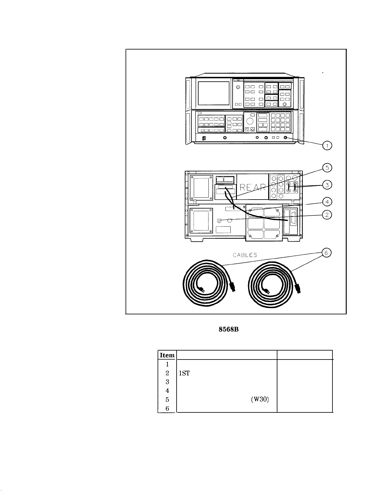
Figure l-l illustrates the instrument with the supplied accessories. In
accordance with international safety standards, both sections of this
instrument are equipped with three-wire ac power cables. Various
power cables are available to connect the HP 8568B to the types of
AC power outlets unique to specific geographic areas. See Figure l-2.
Cables appropriate for the area to which the instrument is originally
shipped are included with the instrument.
1-2 General information
Page 16
IF-Display
Sect ion
RF Section
IF-Display
Sect ion
RF Sect ion
FRONT VIEW
REAR VIEW
Figure l-l. HP 8568B with Accessories Supplied
Description
HP Part Number
Type N (m) to BNC (f) connector 1250-0780
1ST
LO OUT BNC termination
BNC jumper cable (quantity: 2)
HP 11593A
85660-60117
Bus interconnect cable (W31) 85662-60220
Coax interconnect cable
Line power cables (2 each)
(W30) 85662-60093
see Figure l-2
General Information 1-3
Page 17
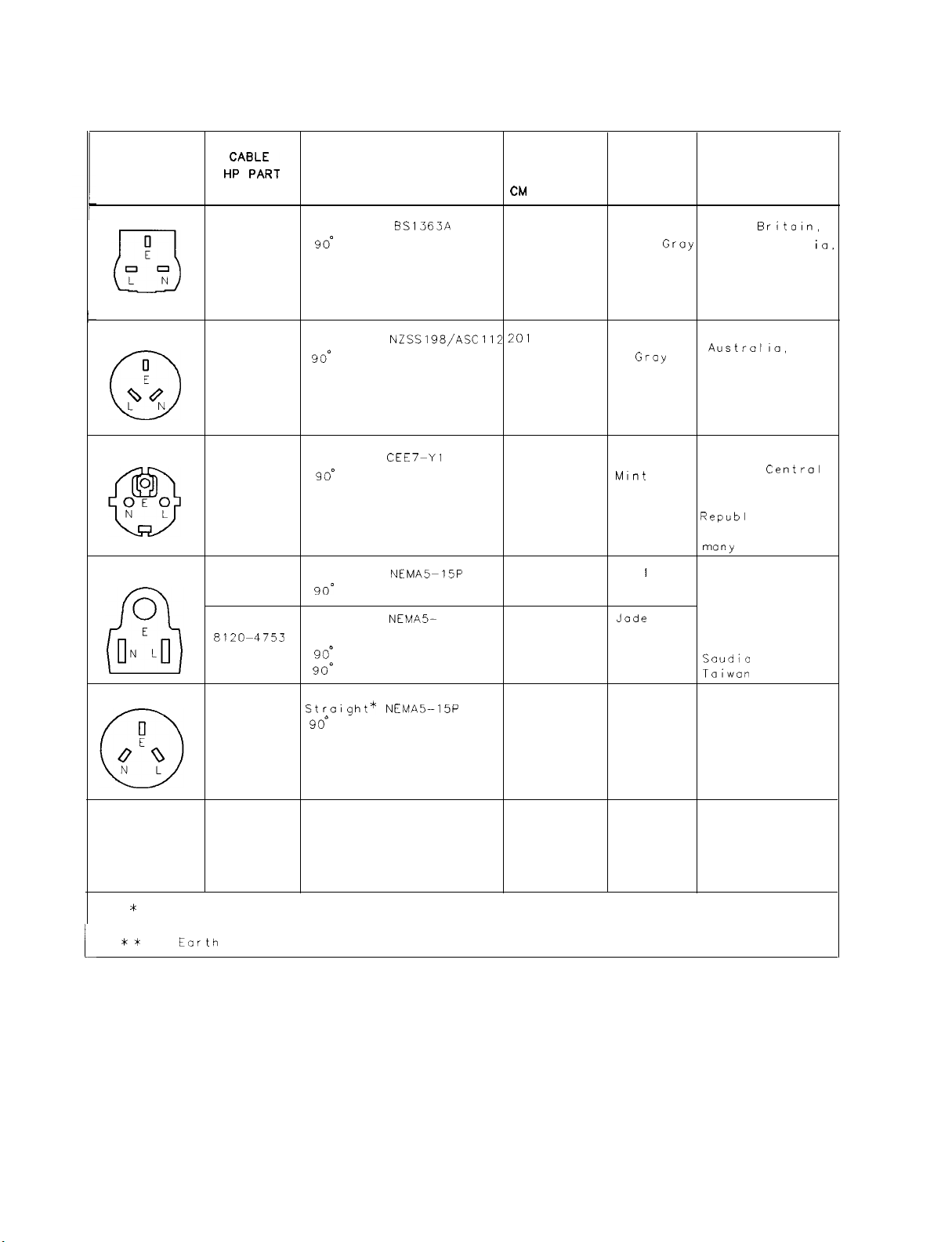
PLUG TYPE * *
Hy;A;T
NUMBER
PLUG
DESCRIPTION
CABLE
LENGTH
a.4
(INCHES)
CABLE
COLOR
FOR USE
IN COUNTRY
250V
250V
250V
125V
250V
8120-1351
8120-1703
8120-1369
8 120-0696
8120-1689
8120-1692
8120-1348
8120-1538
8120-1378
8120-4753
8120-1521
8 120-4754
8120-5182
8120-5181
Straight*
90’
Straight*
9o”
Straight
90’
Straight*
90’
Straight*
Straight
90*
90’
Straight*
90°
BS1363A
NZSS198/ASC112 201
*
CEE7-Yl
NEMA5-15P
NEMA5-
NEMA5-15P
1
15P
229 (90) Mint Gray
Mint
229 (90)
(79)
221 (87)
201 (79)
201 (79)
203 (80)
203 (80)
203 (80)
230 (90)
203 (80)
230 (90)
200 (78)
200 (78)
Mint Gray
Mint
Gray
Gray
Gray
Gray
B I ock
Black
Jade
Gray
Jade Gray
Jade Gray
Jade Gray
Jade Groy
Jade Gray
Great
Cyprus.
Singapore,
Z imbobwe
Argentina,
Austrollo,
New Zealand,
Mainland Chino
East and West
Europe,
African Republic
United Arab
Republ
(unpolarized in
many
United States
Canada,
Japan (100 V or
200 V), Brazil,
Colombia, Mexico
Philippines,
Soudio
Taiwan
ic
nations)
Arabia,
Israel
Britoln,
Niger
centrcl
ia,
*
Port number for plug is industry
HP Part Number for complete cable, including plug
**
E =
t
FORMAT80
Earth
1-4 General Information
Ground,
identifier for plug only. Number shown for cable is
L = Line; N = Neutral.
Figure l-2. AC Power Cables Available
Page 18

Accessories Available
A number of accessories are available from Hewlett-Packard to help
you configure your HP 8568B for your specific needs.
Preamplifiers
Close-Field Probes
75 to 50 ohm
Minimum-Loss Pad
Microwave Limiters
The HP 8447D preamplifier provides a
minimum of 26 dB gain from 100 kHz to
1.3
GHz
to enhance measurements of very
low-level signals.
The HP 11940A and HP 11941A Close-Field
Probes are small, hand-held,
field sensors. The probes can be used to
make repeatable, absolute, magnetic-field
measurements. When attached to a signal
source, the probes can be used to generate a
localized magnetic field for electromagnetic
interference
HP 11941A is specified over a frequency range
of 9 kHz to 30 MHz. The HP 11940A operates
from 30 MHz to 1
The minimum-loss pad (dc - 2.0
number 08566-60122, is a low-VSWR resistive
matching device for making measurements in
75-ohm systems.
The HP 11867A Limiter protects the
instrument input circuits from damage due
to high power levels. It operates over a
frequency range of dc to 1.8
10 W continuous and 100 W peak power.
(EMI)
susceptibility testing. The
GHz.
electromagnetic-
GHz),
HP part
GHz
and is rated
The HP 11693A Limiter is similar to the
HP 11863A but has a frequency range of 0.4
to 12.4
75 W peak power.
HP-IB Cable
Controllers
HP 85650A Quasi-Peak The HP 85650A adds to the spectrum
Adapter
Use HP
The HP 8568B is fully HP-IB programmable.
The preferred controllers are HP 9000
Series 300 computers. Consult your local
Hewlett-Packard service representative for
other recommended controllers and available
software.
analyzer the resolution bandwidth filters and
quasi-peak detection capability specified by
CISPR. Together the quasi-peak adapter and
the spectrum analyzer provide many of the
elements needed for an EM1 receiver system.
GHz
and is rated 1 W continuous and
10833A/B/G/D
HP-IB cables.
General Information
l-5
Page 19

HP
85685A
Preselector
RF
The HP
with an HP
test receiver. It improves spectrum analyzer
measurement sensitivity while providing
overload protection from out-of-band signals.
This enables low-level signals to be monitored
in the presence of high-level ambients. Its
frequency range is 20 Hz to 2
85685A
8568B
RF Preselector can be used
to form a multi-purpose RF
GHz.
Options
Troubleshooting and Service information for the HP
Repair Manual available in the HP 85680B Troubleshooting
and
&pair
Troubleshooting and
They include schematic diagrams, block
diagrams, component location illustrations,
circuit descriptions, repair procedures, and
troubleshooting information.
Service Kits
Several options are available and can be ordered by option number
when you order the instrument. Some of the options are also
available as kits that can be ordered and installed after you have
received your HP 8568B.
Option 001
Option 010
75 ohm (BNC) RF input.
Rack Mount Slide kit. This option supplies the
necessary hardware and installation instructions for
mounting an instrument on slides into a rack of 482.6
mm (19 inch) spacing. The heavy-duty slides are
designed specifically to support the weight of the
HP
approximately 50 kg (112 lbs), the use of this option
is recommended. Option 010 is also available as a kit
(HP part number 5062-6407).
A service kit is available containing
troubleshooting and alignment accessories
for the HP 8568B. The kit includes a test
cable and extender boards. Order the kit as
HP part number 08568-60001. A combined
kit, HP part number 08566-60005 is available
containing accessories for both the HP 8566B
and HP 8568B instruments.
8568B.
Because of the weight of the HP
Manual
and the
&pair
8568B
is
HP 85662A
Manual.
8568B,
1-6 General Information
Option 080
Option 081
Option 400
Option 462
Information Cards in Japanese.
Information Cards in French.
The standard HP 8568B requires that the power line
frequency be 50 or 60 Hz. Option 400 allows the
instrument to operate with a 400 Hz power line
frequency.
This option provides 6 dB bandwidths for making
MIL-STD EM1 measurements. In addition to
enhancing instrument capability for MIL-STD
461D and 462D EM1 measurements, Option 462
spectrum analyzers can still make all commercial
Page 20

EM1 and general-purpose measurements. Option
462 instruments with HP 85662A (top box) serial
prefixes below 3341A were
462A/B/C
(impulse bandwidth).
compatable
with MIL-STD
Option 857
Option 908
Option 910
Option 913
Option 915
The HP
applications. This option provides the cumulative
log fidelity and absolute amplitude performance
necessary for EMC receivers to meet their system
specs.
Rack Mount Flange kit (to mount without handles).
This option supplies the necessary hardware and
installation instructions for mounting an instrument in
a rack of 482.6 mm (19 inch) spacing. Option 908 is
also available as a kit (HP part number 5062-3986).
Extra
Manual and an extra HP 8568B
and Adjustments Manual.
Rack Mount Flanges with Handles (handles provided).
This option supplies the necessary hardware and
installation instructions for mounting an instrument
with handles in a rack of 482.6 mm (19 inch) spacing.
Option 913 is also available as a kit (HP part number
5062-3986).
This option supplies the HP 8568B troubleshooting
and repair manuals.
8568B
Option 857 is used in EMC receiver
HP 8568B Operating and Programming
&formunce lksts
Instruments Covered
by This Manual
This manual contains information for setup and verification of
operation of HP 8568B spectrum analyzers, including those with
Option 001 (75 Ohm RF INPUT), Option 400 (400 Hz operation),
Option 462 (6 dB bandwidths or impulse bandwidths), or Option 857
installed. The procedures in this manual can also be used to setup and
verify the operation of HP 8568A spectrum analyzers that have been
converted into HP 8568B spectrum analyzers through the installation
of an HP 8568AB Retrofit kit (formerly the HP 8568A+OlK Retrofit
Kit).
Serial
Hewlett-Packard makes frequent improvements to its products to
enhance their performance, usability, or reliability. HP service
personnel have access to complete records of design changes to each
type of equipment, based on the equipment’s serial number.
Whenever you contact HP about your instrument, have the complete
serial number available to ensure obtaining the most complete and
accurate information possible.
A serial number label is attached to the rear of each instrument
section. The serial number has two parts: the prefix (the first four
numbers and a letter), and the suffix (the last five numbers). See
Figure 1-3.
Numbers
The first four numbers of the prefix are a code identifying the date of
the last major design change incorporated in your instrument.
General Information
l-7
Page 21
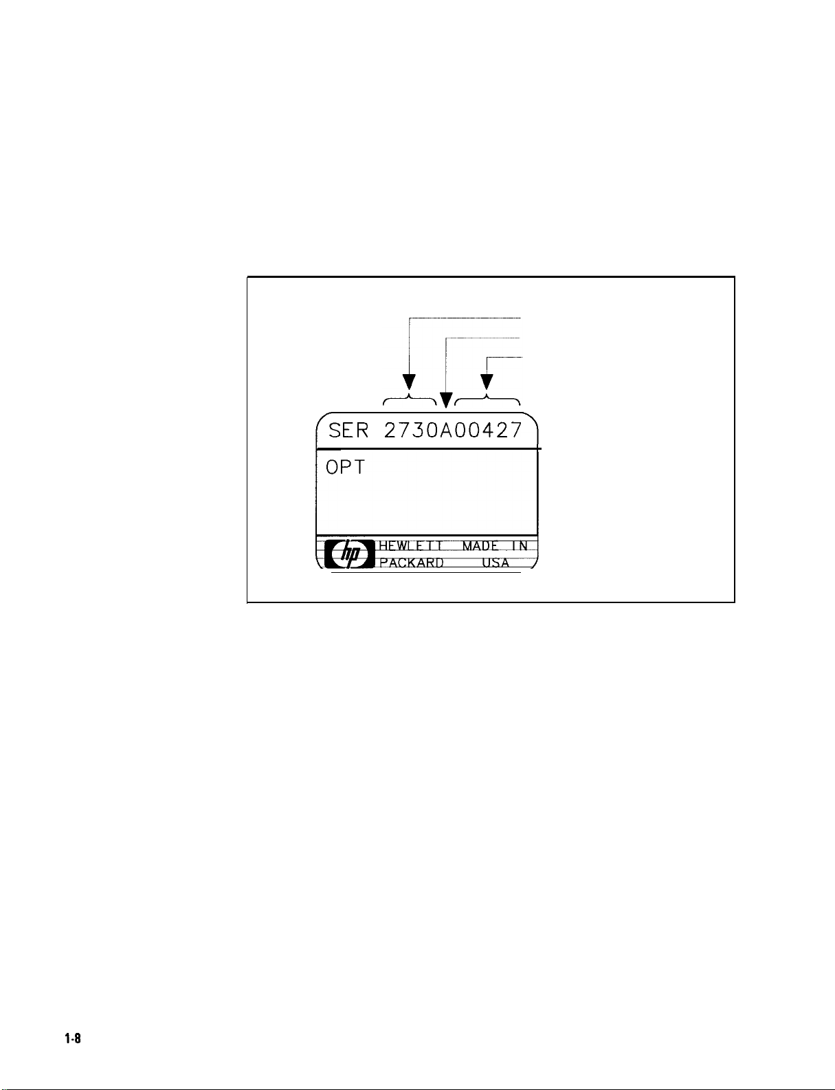
The letter identifies the country in which the instrument was
manufactured. The five-digit suffix is a sequential number and is
different for each instrument. Whenever you list the serial number
or refer to it in obtaining information about your instrument section,
be sure to use the complete number, including the full prefix and the
suffix.
PREFIX
COUNTRY OF ORIGIN
SUFFIX
ER
2730A00427
Figure 1-3. Typical Serial Number Label
l-8
General Information
Page 22

Calibration Cycle
To ensure that the HP 8568B meets the specifications listed in Chapter
3, the operation verification listed in Chapter 5 should be performed
every 6 months.
HP-IB Address
Selection
Bench Operation
The instrument is shipped with the HP-IB address preset to 18 (ASCII
2R). The instrument stores this address in internal RAM memory
which is maintained by a lithium battery in STANDBY and when line
power is removed. This stored address can be changed from the
front panel or on switches located on the RF section’s Al5 controller
assembly. Refer to Chapter 2, “Installation.”
The instrument has plastic feet and
convenience in bench operation. The plastic feet are shaped to make
full-width modular instruments self-aligning when stacked. The
instrument is shipped with front handles attached for ease of moving.
foldaway
tilt stands for
General Information
l-9
Page 23
Electrostatic
Discharge
Information
Electrostatic discharge (ESD) can damage or destroy electronic
components. Therefore, observe the following precautions:
n Be sure that all instruments are properly earth-grounded to prevent
buildup of static charge.
n Before connecting any coaxial cable to an instrument connector for
the first time each day, momentarily short the center and outer
conductors of the cable together.
n Personnel should be grounded with a resistor-isolated wrist strap
before touching the center pin of any connector and before
removing any assembly from the instrument.
n When replacing the instrument’s battery (refer to Replacing the RF
Section Battery in this chapter), be sure to observe the following:
q Perform the work at a static-safe workstation. See Figure l-4.
q Store or transport PC boards only in static-shielding containers.
q Always handle board assemblies by the edges. Do not touch the
edge-connector contacts or trace surfaces with bare hands.
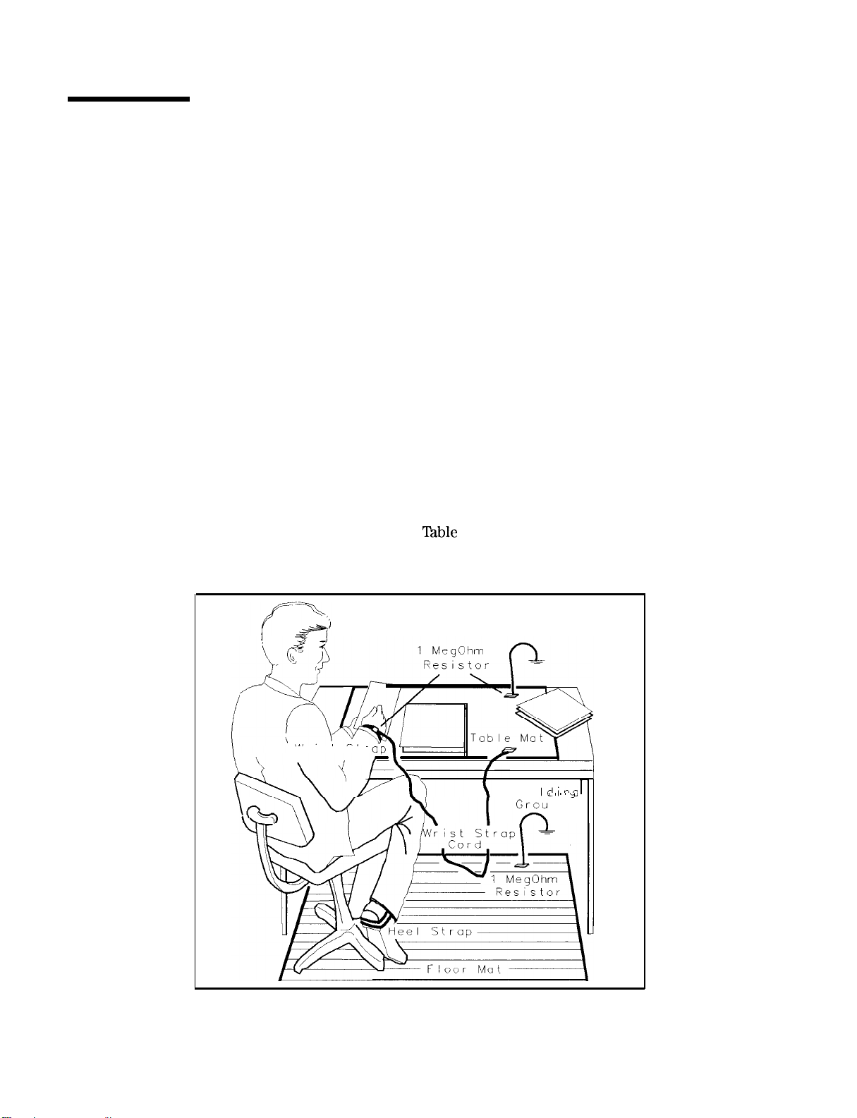
Figure l-4 shows an example of a static-safe workstation. Two types
of ESD protection are shown: a) conductive table mat and wrist strap
combination, and b) conductive floor mat and heel strap combination.
The two types must be used together to ensure adequate ESD
protection. Refer to
nble
l-l for a list of static-safe accessories and
their part numbers.
FORMAT46
Wrist Str
Building
Ground
Bui
Id;nn
” “Y
nd
I
l-10 General Information
Figure l-4. Static-Safe Workstation
Page 24

Static-Safe
Accessories
able
l-l. Static-Safe Accessories
HP Fart
Number
Order the following through any Hewlett-Packard Sales and Service
Office
9300-0797
9300-0980
9300-1383
9300-1169
Set includes: 3M static control mat 0.6 m x 1.2 m (2 ft
x 4 ft) and 4.6 cm (15 ft) ground wire. (The wrist-strap
and wrist-strap cord are not included. They must be
ordered separately.)
Wrist-strap cord 1.5 m (5 ft)
Wrist-strap, color black, stainless steel, without cord,
has four adjustable links and a 7 mm post-type
connection.
ESD heel-strap (reusable 6 to 12 months).
Description
General Information l-l 1
Page 25
Routine
Maintenance
Cleaning the Display
Caution
The inside surface of the glass CRT shield is coated with a thin
metallic film that can be easily damaged. To clean the glass CRT
shield, use thin-film cleaner (HP part number 8500-2163) and a
lint-free cloth. To clean the inside surface of the display glass, remove
the glass CRT shield using the following procedure:
1. Disconnect the ac line power from the instrument sections.
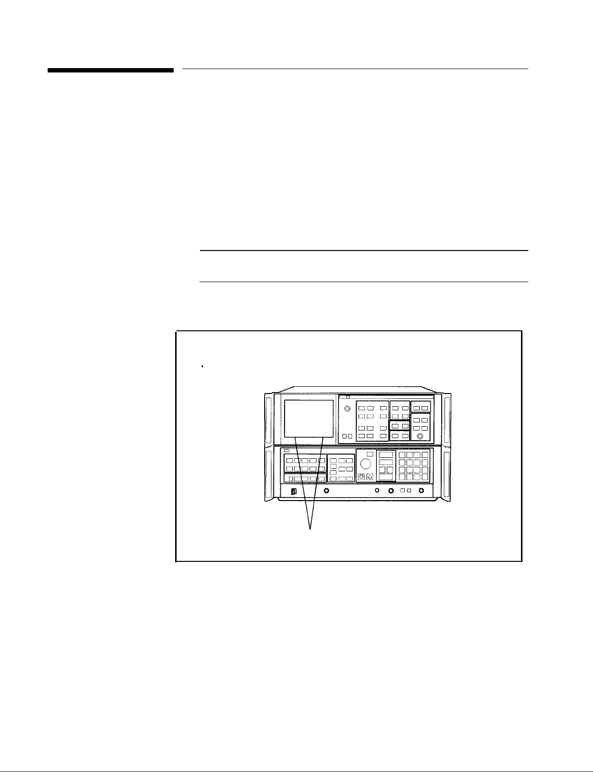
2. Remove the two screws securing the display bezel and CRT glass
shield to the front panel. These screws are located on the bottom
edge of the bezel. See Figure l-5.
While removing the two bezel screws, use caution to prevent the glass
from falling.
3. Remove the bezel and CRT glass shield.
1-12 General Information
Bezel Screws
Figure l-5. Display Bezel Screws
4. Clean the glass using the thin-film cleaner and a lint-free cloth.
5. Replace the glass shield. Place the side of the glass that has the
silver edge towards the CRT.
6. Replace the bezel and two screws.
Page 26

Cleaning the RF
Section’s Fan Filter
The fan on the RF section has a air filter that should be regularly
inspected and cleaned. To clean the air filter perform the following:
1. Disconnect the ac line power from the RF section.
2. Remove the four screws securing the filter cover to the fan on the
RF section. Remove the filter.
3. Clean the filter using a mild soap and water. Dry the filter
thoroughly. If damaged, replace with a new filter (HP part number
85660-00049).
4. Replace the filter and its cover.
Replacing the RF
Section’s Battery
Warning
Warning
Caution
The RF section’s Al5 controller assembly has a battery for
maintaining internal RAM memory. This memory is primarily
used for storing instrument states, error correction data, and
DLPs
(downloadable programs). Under normal conditions, the
battery should typically last a minimum of three years. Use the
following procedure to replace the battery. Refer to the HP
Troubleshooting and Repair Manual for the HP part number.
Battery
or attempt to recharge this battery. Dispose of discharged
battery in a safe manner.
Changing the battery
requires the removal of the RF section’s protective bottom cover.
This should be performed only by a qualified service person.
Refer all such servicing of the instrument to qualified service
persons.
ESD (Electrostatic Discharge) can damage or destroy electronic
components. Work at a static-safe workstation when replacing the
battery.
1. Place the HP
BTl
contains lithium iodide. Do not incinerate, puncture,
BTl
on the Al5 controller assembly
8568B
on a static-safe workstation. Refer to
“Electrostatic Discharge Information” in this chapter.
8568OB
2. Disconnect the ac line power from the instrument sections. Place
the HP 8568B upside down on the work surface so that the
bottom of the RF section is facing up.
General Information
l-13
Page 27
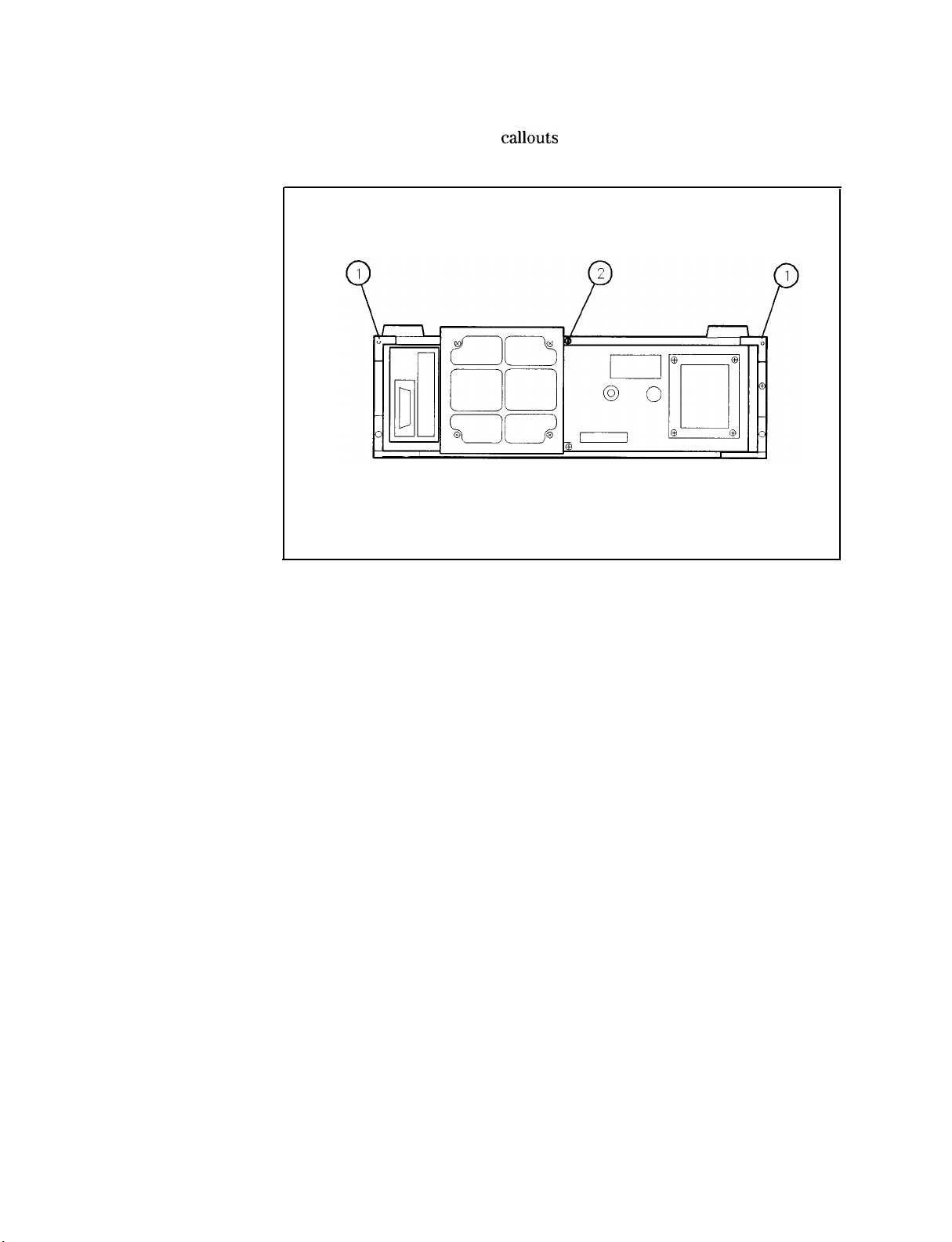
3. Using a screw driver, remove the two bottom RF section rear
panel bumpers. See
callouts
1 in Figure l-6.
TOP DOWN
Figure 1-6. Removing the Bottom Cover
4. Back out screw 2 (Figure l-6) causing the cover to unseat from
the front frame. When the cover is clear of the front frame, lift
the cover up to remove it.
l-14 General Information
Page 28
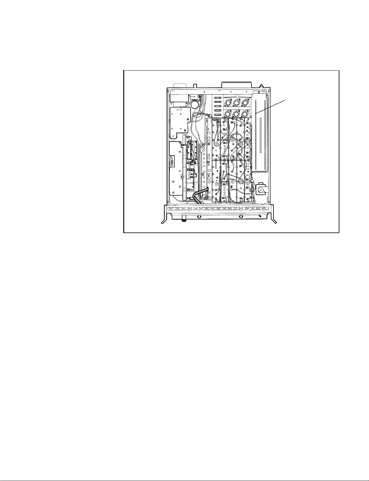
5. Remove the cover from the Al5 controller assembly. See
Figure l-7.
Al5
CONTROLLER
ASSEMBLY
Figure l-7. Location of Al5 Controller Assembly
General Information 1-15
Page 29
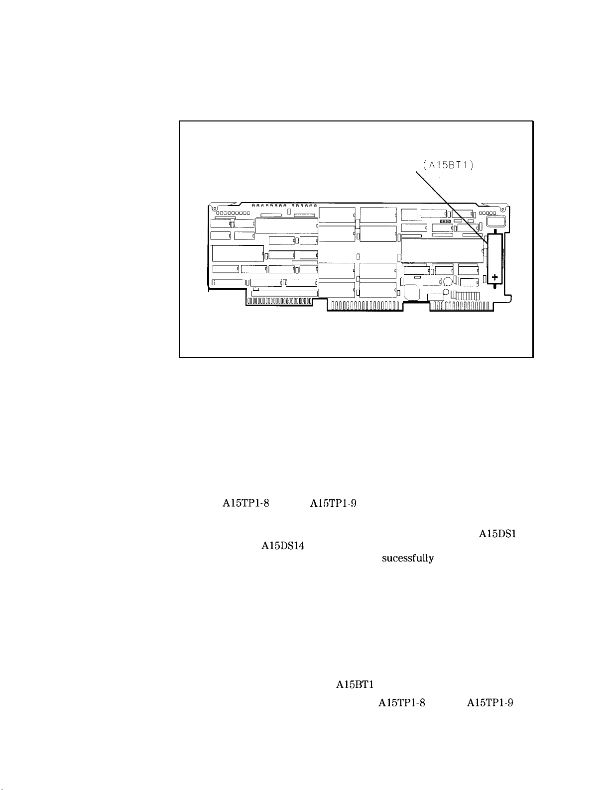
6. Remove the Al5 controller assembly. Locate the battery on the
Al5 assembly. Figure l-8 shows the location of the battery.
Battery
(A15BTl)
Figure 1-8. Location of Battery on Al5 Controller Assembly
7. Replace the battery with a new one (HP part number 1420-0331).
Be sure to install the battery with the polarity shown in
Figure l-8.
8. Replace the Al5 controller assembly.
9. Reconnect the power cables to the IF and RF sections.
10. Connect a jumper wire between the Al5 controller test points
A15TPl-8 T3 and A15TPl-9 ST (to erase and initialize Al5
controller nonvolitile memory).
11. Set the LINE switch to ON. The Al5 controller LED’s A15DSl
through
indicating the Al5 controller has
A15DS14
should all turn on, then turn off, sequentially,
sucessfully
executed self-test. If
they do not, the Al5 controller might be damaged or improperly
installed. In addition, all front panel LED’s should turn on
momentarily, indicating the HP 8566B has performed its power-on
pretest.
In addition to normal HP 8568B power-up HP-IB address and
firmware revision information, a BATTERY flag should appear on
the CRT, indicating that information previously stored in the Al5
controller nonvolitile memory has been lost or erased. Normally
the BATTERY flag appears after several years of use to indicate
that the lithium battery A15BTl needs to be replaced.
12. Remove the jumper wire between A15TPl-8 T3 and A15TPl-9 ST.
1-16 General Information
Page 30

13. Set the LINE switch to STANDBY and then to ON. The HP 8568B
should power up normally, without any flags displayed on the
CRT.
14. Set the LINE switch to STANDBY and remove the power cable
from the rear of the RF section.
15. Install the controller cover,
16. Replace the RF section bottom cover and the two rear feet.
17. Place the HP 8568B top side up and reconnect the power cable to
the RF section.
18. Set the LINE switch to ON and allow a 2-hour warm-up.
19. Recalibrate the instrument with the following steps. (For a more
complete description of the calibration, refer to the HP
Operating
and Programming Manual.)
8568B
a. Connect the front-panel CAL OUTPUT signal to the SIGNAL
INPUT 2.
b. Press
[RECALL)
8, and then adjust the front-panel AMPTD CAL
adjust for a marker amplitude of -10.00 dBm.
c. Press
cm]
9, and then adjust the front-panel FREQ ZERO
adjust for maximum signal amplitude.
d. Press
@iiF]
[FREQUENCY SPAN]
w
to load the error correction
data in the instrument’s memory.
General Information l-17
Page 31

Ordering
Information
Parts can be ordered from any Hewlett-Packard Sales and Service
Office. Refer to
order a part or assembly, quote the Hewlett-Packard part number,
indicate the quantity required, and address the order to the nearest
Hewlett-Packard Office.
To order a part that is not listed in the replaceable parts table, include
the instrument model number, the description and function of the
part, and the number of parts required. Address the order to the
nearest Hewlett-Packard Sales and Service Office.
Table
1-3 for a listing of sales and service offices. To
Direct Mail Order
System
Direct Phone-Order
System
Within the USA, Hewlett-Packard can supply parts through a direct
mail order system. Advantages of using the system are as follows:
w
Direct ordering and shipment from the HP Support Materials
Organization in Roseville, California.
n No maximum or minimum on any mail order. (There is a minimum
order amount for parts ordered through a local Hewlett-Packard
Sales and Service Office when the orders require billing and
invoicing.)
n Prepaid transportation. (There is a small handling charge for each
order.)
I
No invoices.
To provide these advantages, a check or money order must accompany
each order. Mail-order forms and specific ordering information is
available through your local Hewlett-Packard Sales and Service Office.
Within the USA, a phone order system is available for regular and
hotline replacement parts service. A toll-free phone number is
available, and Mastercard and Visa are accepted.
Regular Orders: The toll-free phone number, (800) 227-8164, is
available 6 AM to 5 PM, Pacific time, Monday through Friday. Regular
orders have a 4 day delivery time.
1-16 General Information
Hotline Orders: Hotline service for ordering emergency parts is
available 24 hours a day, 365 days a year. There is an additional
hotline charge to cover the cost of freight and special handling.
The toll-free phone number, (800) 227-8164, is available 6 AM to 5 PM,
Pacific time, Monday through Friday and (916)
after-hours, weekends, and holidays. Hotline orders are normally
delivered the following business day.
785-8HOT
is available
Page 32

Returning the
Instrument for
Service
The instrument may be shipped in environments within the following
limits:
Temperature . . . . . . . . . . . . . . . . . . . . . . . . . . . -40 “C to + 75
Humidity . . . . . . . . . . . . . . . . . . . . . 5% to 90% at 0 “C to 40
Altitude . . . . . . . . . . . . . . . . Up to 15,240 meters (50,000 feet)
The instrument should be protected from temperature extremes which
may cause condensation within the instrument.
“C
“C
Service
lhgs
Original Packaging
Note
If you are returning the instrument to Hewlett-Packard for servicing,
fill in and attach a blue service tag to each instrument section.
(Service tags are supplied at the end of this chapter.)
Please be as specific as possible about the nature of the problem. If
you have recorded any error messages that appeared on the screen or
have any other specific data on the performance of the instrument,
please send a copy of this information with the instrument.
To protect the front panel, the front handles must be attached to each
instrument section before shipping.
It is recommended that the original factory packaging materials
be retained for use when shipping the instrument. Because of the
combined weight of the two instrument sections is approximately 50
kg (112 lbs), do not package the instrument sections fastened together
as one unit. The instrument sections must be separated and packaged
in separate containers. Pack each section in the original factory
packaging materials if they are available. See Figure 1-9. Refer to
Table l-2 for the part numbers of items listed in the figure. Original
materials are available through any Hewlett-Packard office.
General Information
l-19
Page 33

(2 PLACES)
mounted for shipment.
Figure l-9. Factory Packaging Materials for Each Section
‘Ihble
1-2.
F&tory
Packaging Materials
Item
I
1
3
Description
1
Outer Box
2 Inner Box
I
/Inner
Qty HP Part Number
1 921l-4487
1
I I
Foam Pad 1 2
5180-2320
15180-2319
I
l-20 General Information
Page 34

Other Packaging
Caution
Note
Instrument damage can result from using packaging materials other
than those specified. Never use styrene pellets as packaging materials.
They do not adequately cushion the instrument or prevent it from
shifting in the carton. They cause instrument damage by generating
static electricity.
To protect the front panel, the front handles should be attached to
each instrument section before shipping.
You can repackage the instrument with commercially available
materials, as follows:
1. Separate the two instrument sections.
2. Attach a completed service tag to each of the sections.
3. Wrap each section in antistatic plastic to reduce the possibility of
damage caused by electrostatic discharge.
4. Use a strong shipping container. A double-walled, corrugated
cardboard carton of
adequate. The carton must be large enough and strong enough to
accommodate the instrument. Allow at least 3 to 4 inches on all
sides of the instrument for packing material.
5. Surround the instrument with 3 to 4 inches of packing material, to
protect the instrument and prevent it from moving in the carton.
If packing foam is not available, the best alternative is S.D.-240 Air
Cap from Sealed Air Corporation (Hayward, California 94545). Air
Cap looks like a plastic sheet filled with
the pink (antistatic) Air Cap to reduce static electricity. Wrapping
the instrument section several times in this material should both
protect the instrument section and prevent it from moving in the
carton.
159-kg (350~lb)
bursting strength is
l-l/4
inch air bubbles. Use
6. Seal the carton with strong nylon adhesive tape.
7. Mark the carton
8. Retain copies of all shipping papers.
FRAGILE, HANDLE WITH CARE.
General Information
1-21
Page 35

Sales and Service
Offices
Hewlett-Packard Sales and Service Offices provide worldwide support
for Hewlett-Packard products. To obtain servicing information or to
order replacement parts, contact the nearest Hewlett-Packard Sales
and Service Office listed in
provide essential information, which includes model numbers, serial
numbers, or assembly part numbers.
Able
l-3. In any correspondence, always
1-22 General Information
Page 36

‘Ihble
1-3. Hewlett-Packard Sales and Service Offices
US FIELD OPERATIONS
HEADQUARTERS
Hewlett-Packard Company
19320 Pruneridge Avenue
Cupertino, CA 95014, USA
(800) 752-0900
California
Hewlett-Packard Co.
1421 South Manhattan Ave.
Fullerton, CA 92631
(714) 999-6700
Hewlett-Packard Co.
301 E. Evelyn
Mountain View, CA 94041
(415) 694-2000
Colorado
Hewlett-Packard Co.
24 Inverness Place, East
Englewood, CO 80112
(303) 649-5000
Georgia
Hewlett-Packard Co.
2000 South Park Place
Atlanta, GA 30339
[404)
955- 1500
Illinois
Hewlett-Packard Co.
5201 Tollview Drive
Rolling Meadows, IL 60008
1708)
255-9800
New Jersey
Hewlett-Packard Co.
150 Green Pond Road
Rockaway, NJ 07866
1201)
627-6400
Ikxas
Hewlett-Packard Co.
330
E. Campbell Rd.
Richardson, TX 75081
:214)
231-6101
EUROPEAN OPERATIONS
HEADQUARTERS
Hewlett-Packard S.A.
150, Route du
12 17 Meyrin
Nant-d’Avri1
2/Geneva
Switzerland
(41 22) 780.8111
France
Hewlett-Packard France
1 Avenue Du Canada
Zone D’Activite De Courtaboeuf
F-91947 Les Ulis Cedex
France
(33 1) 69 82 60 60
Germany
Hewlett-Packard
GmbH
Hewlett-Packard Strasse
6380 Bad Homburg v.d.H
Germany
(49 6172) 16-O
Great Britain
Hewlett-Packard Ltd.
Eskdale Road, Winnersh Triangle
Wokingham, Berkshire RGl 1 5DZ
England
(44 734) 696622
INTERCON
OPERATIONS
HEADQUARTERS
Hewlett-Packard Company
3495 Deer Creek Rd.
Palo Alto, California 94304-1316
(415) 857-5027
Australia
Hewlett-Packard Australia Ltd.
31-41 Joseph Street
Blackburn, Victoria 3130
(61 3) 895-2895
Canada
Hewlett-Packard (Canada) Ltd.
17500 South Service Road
Trans-Canada Highway
Kirkland, Quebec H9J
2X8
Canada
(514) 697-4232
Japan
Yokogawa-Hewlett-Packard Ltd.
1-27-15 Yabe, Sagamihara
Kanagawa 229, Japan
(81 427) 59-1311
China
China Hewlett-Packard, Co.
38 Bei San Huan Xl Road
Shuang Yu Shu
Hai Dian District
Beijing, China
(86 1) 256-6888
Singapore
Hewlett-Packard Singapore
Pte. Ltd.
1150 Depot Road
Singapore 0410
(65) 273 7388
Wwan
Hewlett-Packard l%iwan
8th Floor, H-P Building
337 Fu Hsing North Road
nipei,
Taiwan
(886 2) 712-0404
General Information 1-23
Page 37

Installation
2
What You’ll Find in
This Chapter
This chapter describes the process of getting the HP 8568B spectrum
analyzer ready to use. The process includes initial inspection and
installing the unit. Before installing the HP
the warnings, cautions, and notes listed in “Safety” below.
1
If you are
Standard Instruments” in this chapter.
n
To
install Option 908 or 913 instruments, refer to “To Install Option
908 and 913 Instruments” in this chapter.
n To install Option 010 instruments, refer to “To Install Option 010
Instruments” in this chapter.
Safety .............................................. 2-l
Preparation for Use
Initial Inspection
Operating Environment
Power Requirements
To Install Standard Instruments
To Install Option 908 and 913 Instruments
To Install Option 010 Instruments
To Set the HP-IB Address
From the Front Panel
From the HP-IB Bus
From the HP-IB Address Switch
not
installing the instrument in a rack, refer to “To Install
..................................
..................................
............................
...............................
.......................
....................
............................
.............................
..............................
8568B,
be sure to read all
.............
...................
2-3
2-3
2-3
2-3
2-4
2-7
2-13
2-20
2-20
2-20
2-20
Safety
Before installing or operating this instrument, you should familiarize
yourself with the safety marking on the instrument and the safety
instructions in the manuals. The instrument has been manufactured
and tested in accordance with international safety standards.
However, to ensure safe operation of the instrument and personal
safety of the user, the cautions and warnings in the manuals must be
followed. Refer to the summary of the safety information located
near the front of this manual.
Installation
2-l
Page 38

Warning
F’ailure
injury. Before turning on the HP
protective earth terminals to the protective conductor of the
main power cable. Insert the main power cable plug only into a
socket outlet that has a protective earth contact. DO NOT defeat
the earth-grounding protection by using an extension cable,
power cable, or autotransformer without a protective ground
conductor. If you are using an autotransformer, make sure its
common terminal is connected to the protective earth contact of
the power source outlet socket.
to ground the instrument properly can result in personal
8568B,
you must connect its
Warning
Warning
Caution
Power is still applied to this instrument with the
in STANDBY. There is no Off position for the
remove power from the instrument, it is necessary to remove the
power cable from the rear of each instrument section.
Because the combined weight of the instrument sections is
approximately 112 pounds, use appropriate caution when moving
or installing.
Before switching on this instrument, make sure it is adapted to
the voltage of the ac power source as described in the following
procedures. Failure to set the ac power input to the correct voltage
could cause damage to the instrument when the ac power cable is
plugged in.
m
m
switch
switch.
lb
2.2
Installation
Page 39

Preparation for
Use
Initial Inspection
Operating
Environment
Inspect the shipping container for damage. If the shipping container
or cushioning material is damaged, keep it until you have verified
that the contents are complete and you have tested the instrument
mechanically and electrically.
Contents of the shipment are shown in Figure l-l. If the contents
are incomplete or if the instrument does not pass the operation
verification tests (procedures are provided in Chapter
nearest Hewlett-Packard office. If the shipping container is damaged
or the cushioning material shows signs of stress, also notify the
carrier. Keep the shipping materials for the carrier’s inspection. The
HP office will arrange for repair or replacement without waiting for a
claim settlement.
If the shipping container and cushioning material are in good
condition, retain them for possible future use. You may wish to ship
the instrument to another location or to return it to Hewlett-Packard
for service. Chapter 1, “General Information, ” provides instructions
for repackaging and shipping the instrument.
The instrument may be operated in environments within the following
limits:
Temperature . . . . . . . . . . . . . . . . . . . . . . . . . . . . . . 0 “C to
Humidity . . . . . . . . . . . . . . . . . . . . . 5% to 90% at 0 “C to 40
Altitude . . . . . . . . . . . . . . . . . . up to 4,572 meters (15,000 feet)
5),
notify the
+55 “C
“C
Power Requirements
The instrument should be protected from temperature extremes which
might cause condensation within the instrument.
The HP 8568B requires a power source of 100, 120, 220, or 240 Vat
+ 5%
sections combined is less than 650 VA.
-lo%,
50-60 Hz. Power consumption for the instrument
Installation 2-3
Page 40

To Install Standard
Instruments
1. Place the RF section right-side up on a level work surface.
2. Place the IF-Display section on top of the RF section, offset far
enough forward to allow the RF section hooks to engage the
IF-Display section frame when slid back. Slide the IF-Display
section back until the RF section hooks catch the bottom of the
IF-Display section.
3. Line up the rear-panel lock feet, and tighten the thumb screws on
both lock feet.
4. Connect cable W31 between IF-Display section 52 and RF section
J6. See Figure 2-l.
5. Connect cable
Jl.
W30
between IF-Display section Jl and RF section
w30
32
w31 w37
Jl
J4 J5
W38
2-4 Installation
Figure 2- 1. Rear-Panel Cable Connections
6. Determine the ac line voltage to be used.
7. On each instrument section, slide open the power module’s fuse
cover (located on the rear panel). See Figure 2-2. Push the
fuse-pull lever to the left. Remove the fuse.
Page 41

Line Voltage Setting Card Fuse
Figure 2-2. Voltage Selector Board and Fuse
8. On each power-line module, check the voltage selector card for
the proper ac line voltage. The card’s voltage setting should
be visible on the card. See Figure 2-2. If you need to select a
different ac line voltage setting, perform the following:
a. Use needle-nose pliers to pull out the voltage-selector card.
Rotate the card so that the voltage label corresponding to the
actual line voltage will appear in the module window.
b. Push the card back into its slot.
Installation 2-5
Page 42

9. Check the fuse to make sure it is of the correct rating and type
for the ac line voltage selected. Fuse ratings for different line
voltages are indicated in the following table.
Note
ac Line Voltage IF-Display Section
100/120
220/240
10. Insert the correct fuse, and push the fuse-pull lever into its
normal right-hand position.
11. Connect the ac line power cords.
12. If the HP
HP-IB Address” in this chapter.
13. When you turn your instrument on for the first time, you should
perform the verification tests in Chapter 5. Refer to the
Operation and Programming Manual for instructions on using
the instrument.
Cables W37 and
ports to the HP
without the HP 85650A Quasi-Peak adapter, W37 and W38 must be
connected for the instrument to operate.
2 amperes FAST BLO 2 amperes FAST BLO
HP nart number 2110-0002 HP
1 ampere SLOW BLO 1 amperes SLOW BLO
HP part number 2110-0007 HP part number 2110-0007
8568B
will be remotely controlled, refer to “To Set the
W38
are removed for connection of the IF and VIDEO
85650A
Quasi-Peak adapter. If the instrument is used
RF Section
Dart
number 2110-0002
HP8568B
1
2-6 Installation
Page 43

To Install Option
908 and 913
Instruments
Option 908 contain the necessary hardware to mount the HP
without handles in a rack of 482.6 mm (19 in) spacing. Option 913
mounts the HP
1. Remove the front-handle trim from each side of the RF and
IF-Display sections. See
8568B
with handles.
callout
1 in Figure 2-3.
8568B
Figure 2-3. Removing the Handles and Trim
2. Remove the three screws securing each handle, and remove the
handles. See
callouts
2 and 3 in Figure 2-3.
Installation 2-7
Page 44

3. The information-card tray located on the bottom of the
RF-Display section requires a space of approximately 2 cm
below the instrument when rack mounting. See
callout
1 in
Figure 2-4. (No filler strip is provided.) If you wish to remove
the information-card tray, remove the feet and tilt stands. See
callouts
2 and 3 in Figure 2-4.
Figure 2-4. Removing the Information-Card Tray
2-6 Installation
Page 45

4. On each instrument section, attach the rack mount flange (and
front handles for Option 913) using the three
screws provided in the kit. See Figure 2-5.
RACK MOUNT
M4x0.7~16
pan-head
Figure 2-5. Attach the Rack Mount Flanges
5. Determine the ac line voltage to be used.
Installation 2-9
Page 46

6. On each instrument section, slide open the power module’s
fuse door (located on the rear panel). See Figure 2-6. Push the
fuse-pull lever to the left. Remove the fuse.
Note
Although Figure 2-6 shows the two instrument sections connected
together, they will be mounted separately in the rack.
2-10
Installation
Line Voltage SettingLine Voltage Setting CardCard
FuseFuse
Figure 2-6. Voltage Selector Board and Fuse
7. On each power-line module, check the voltage selector card for
the proper ac line voltage. The card’s voltage setting should
be visible on the card. See Figure 2-6. If you need to select a
different ac line voltage setting, perform the following:
a. Use needle-nose pliers to pull out the voltage-selector card.
Rotate the card so that the voltage label corresponding to the
actual line voltage will appear in the module window.
b. Push the card back into its slot.
Page 47

8. Check the fuse to make sure it is of the correct rating and type
for the ac line voltage selected. Fuse ratings for different line
voltages are indicated in the following table.
ac Line Voltage
100/120
2 FAST BLOamperes 2 FAST BLOamperes
IF-Display Section RF Section
HP part number 2110-0002 HP part number 2110-0002
220/240
1 SLOW BLOampere 1 SLOW BLOamperes
HP part number 2 110-0007HP part number 2 110-0007
9. Insert the correct fuse, and push the fuse-pull lever into its
normal right-hand position.
10. Bolt each instrument section into the rack from its rack mount
flange. Place the IF-Display section just above the RF section.
11. Connect cable W31 between IF-Display section
52
and RF section
J6. See Figure 2-7.
W30
12. Connect cable
between IF-Display section Jl and RF section
Jl.
J2
Jl
J4
J5
Figure 2-7. Rear-Panel Cable Connections
Installation
2-l
1
Page 48

13. Connect the ac line power cords.
14. If the HP
8568B
will be remotely controlled, refer to “To Set the
HP-IB Address” in this chapter.
15. When you turn your instrument on for the first time, you should
perform the verification tests in Chapter 5. Refer to the
Operation and Programming Manual for instructions on using
HP8568B
the instrument.
Cables W37 and W38 are removed for connection of the IF and VIDEO
ports to the HP 85650A Quasi-Peak adapter. If the instrument is used
without the HP 8565OA Quasi-Peak adapter, W37 and W38 must be
connected for the instrument to operate.
2-12 Installation
Page 49

To Install Option
010 Instruments
Option 010 mounts the HP 8568B on slides in a rack of 482.6 mm
(19 in) spacing. (Option 010 also contains adapters for mounting in
non-HP racks.)
1. Remove the strap handle on the IF-Display section’s left side
panel.
2. Remove the right-rear lock foot, and the right-rear top foot from
the IF-Display section. Slide the right-side cover off to the rear.
Install the right-side cover included in the kit, and replace the
rear feet.
3. Remove the front-handle trim from each side of the RF and
IF-Display sections. See
callout
1 in Figure 2-8.
Figure 2-8. Removing the Handles and Trim
4. Remove the three screws securing each handle, and remove the
handles. See
callouts
2 and 3 in Figure 2-8.
Installation 2-13
Page 50

5. The information-card tray located on the bottom of the
RF-Display section requires a space of approximately 2 cm
below the instrument when rack mounting. See
callout
1 in
Figure 2-9. (No filler strip is provided.) If you wish to remove
the information-card tray, remove the feet and tilt stands. See
callouts
2 and 3 in Figure 2-9.
I
Figure 2-9. Removing the Information-Card Tray
6. Place the RF section right side up on a level work surface.
7. Place the IF-Display section on top of the RF section, offset far
enough forward to allow the RF section hooks to engage the
IF-Display section frame when slid back. Slide the IF-Display
section back until the RF section hooks catch the bottom of the
IF-Display section.
8. Line up the rear-panel lock feet, and tighten the thumb screws on
both lock feet.
9. Attach the 10-l/2 inch handles with flanges as shown in
Figure 2-10.
2-14 Installation
Page 51

.,@
,
.,p
“./p
,
P
,..’
Figure 2-10. Attaching the Rack Handles and Flanges
10. Connect cable W31 between IF-Display section 52 and RF section
J6. See Figure 2-l 1.
11. Connect cable
Jl.
W30
between IF-Display section Jl and RF section
w30
w31
Jl
J4
w37
W38
J5
Figure 2-l 1. Rear-Panel Cable Connections
Installation 2-15
Page 52

12. Determine the ac line voltage to be used.
13. On each instrument section, slide open the power module’s fuse
door (located on the rear panel). See Figure 2-12. Push the
fuse-pull lever to the left. Remove the fuse.
Line Voltage Setting
Card
Fuse
Figure 2-12. Voltage Selector Board and Fuse
14. On each power-line module, check the voltage selector card for
the proper ac line voltage. The card’s voltage setting should
be visible on the card. See Figure 2-11. If you need to select a
different ac line voltage setting, perform the following:
a. Use needle-nose pliers to pull out the voltage-selector card.
Rotate the card so that the voltage label corresponding to the
actual line voltage will appear in the module window.
b. Push the card back into its slot.
2-16 Installation
Page 53

15. Check the fuse to make sure it is of the correct rating and type
for the ac line voltage selected. Fuse ratings for different line
voltages are indicated in the following table.
ac Line Voltage IF-Display Section RF Section
100/120
220/240
16. Insert the correct fuse, and push the fuse-pull lever into its
normal right-hand position.
17. Attach one slide inner-member bracket to each side of the
instrument using two M5x0.8~10 pan-head screws per side. See
callout
in 1 of Figure 2-13.
2
amperes FAST
HP part number 2110-0002 HP part number 2110-0002
1
ampere
HP part number 2110-0007 HP part number 2110-0007
SLOW BLO
BLO
2
amperes
1
amperes
FAST BLO
SLOW BLO
Figure 2-13. Attaching the Inner-Member Brackets
18. Mounting in an HP System Rack Cabinet:
a. Insert two Unistrut nuts,
the two vertical columns on the left side of the system cabinet.
Insert two Unistrut nuts into each of the two vertical columns
on the right side of the system cabinet.
b. Bolt an outer slide mount to the Unistrut nuts in each side of
the systems cabinet, using four
side. See
callout
in 3 of Figure 2-13.
callout
2 in Figure 2-13, into each of
M5x0.8~12
pan-head screws per
Installation
2-17
Page 54

c. Expand the outer slide mounts to their full length. Mount the
instrument onto the system cabinet by bolting the outer slide
mount to the inner-member bracket on the instrument, using
three
M5x0.8~12
flat-head screws per side.
Note
If any binding is encountered in the slides after mounting, it will be
necessary to slightly move the Unistrut nuts. While supporting the
instrument, loosen one of the Unistrut nuts. Adjust the slides slightly
until they operate freely. Retighten the Unistrut nut.
19. Mounting in a Non-HP System Rack Cabinet:
a. Using hole pattern “B,” see Figure 2-14, attach one adapter
bracket to the front of each outer slide mount, using two
M4x0.8~12
flat-head screws and nuts per bracket.
2-18 Installation
Figure 2-14. Slide Adapter for Non-HP System Rack Cabinets
Page 55

b. Using hole pattern “B,” attach one adapter bracket to the
rear of each outer slide mount, using two
screws and nuts per bracket.
c. Bolt an outer slide mount to each side of the system rack
cabinet using
nuts provided in the kit if the rack mounting strips have
through-holes.
M5x0.8~12
pan-head screws. Use the bar
M5x0.8~12
pan-head
Note
Note
If any binding is encountered in the slides after mounting, it will be
necessary to slightly move the adapter brackets. While supporting
the instrument, loosen one of the adapter brackets. Adjust the slides
slightly until they operate freely. Retighten the adapter brackets.
20. Connect the ac line power cords.
21. If the HP 8568B will be remotely controlled, refer to “‘Ib Set the
HP-IB Address” in this chapter.
22. When you turn your instrument on for the first time, you should
perform the verification tests in Chapter 5. Refer to the HP
Operation and Programming Manual for instructions on using
the instrument.
Cables W37 and W38 are removed for connection of the IF and VIDEO
ports to the HP 85650A Quasi-Peak adapter. If the instrument is used
without the HP 85650A Quasi-Peak adapter, W37 and W38 must be
connected for the instrument to operate.
8568B
Installation 2-19
Page 56

To Set the HP-IB
Address
The HP-IB address is used in remote programming to identify the
instrument. The decimal address is preset at the factory to 18 (ASCII
2R). Addresses may be decimal 0 through 30. The HP-IB address can
be changed manually from the instrument’s front panel, remotely via
the HP-IB bus, or by setting the instrument’s internal address switch.
The internal address switch is comprised of five switches located
on the Al5 controller assembly in the RF section. These switches
(A15SWl A2 - A6) determine the HP-IB address to be used at
instrument “power-up.” These switches are preset at the factory to
binary 11111 (decimal
address stored in RAM memory (or to the default value 18, if the
contents of RAM memory are ever lost due to a battery failure, and so
on). If the switches are set to a value other than 31, the instrument
will always reset the HP-IB address to this value at power-up.
31),
which sets the instrument to the HP-IB
From the Front Panel
From the HP-IB Bus
From the HP-IB
Address Switch
Warning
To enter a new address from the front panel:
1.
Press
CSHIFT) (EELi]
2. Use the number keypad to enter the new decimal address.
3. Terminate the entry by pressing
HP-IB address and stores the new address value in RAM memory.
To enter a new address via the HP-IB bus, refer to the KSP command
in the
HP 8568B Operating and Programming Manual.
Changing the HP-IB address by resetting the address switch
on the Al5 Controller assembly requires the removal of the RF
section’s protective bottom cover. This should be performed
only by a qualified service person. Refer all such servicing of the
instrument to qualified service persons.
p.
IHz).
This changes the current
2-20
Installation
Page 57

1. Disconnect the ac line cord from the RF section.
2. Using a screw driver, remove the two RF-section rear panel
bumpers. See
callout
1 in Figure 2-15.
TOP DOWN
Figure 2-15. Removing the Bottom Cover
3. Back out screw 2 (see Figure 2-15) and the cover unseats from the
front frame. When the cover is clear of the rear frame, remove the
cover by lifting up.
4. Remove the cover from the Al5 controller assembly. See
Figure 2-16 to locate the assembly.
Installation 2-21
Page 58

Al5 CONTROLLER
ASSEMBLY
Locat
ion
of HP-IB
Switch)
Figure 2-16. Location of Al5 Controller Assembly
5. Locate the address switch A15SWl as shown in Figure 2-16
and Figure 2-17. Change the switch’s setting according to the
information given below.
The switch comprises six segments, Al through A6. Al must
always be set to logic 1. Each of the remaining five segments, A2
through A6, corresponds to one of the digits of a 5-digit binary
equivalent of the address. See Figure 2-17. The switch is preset at
the factory to binary 11111 (decimal 31). This is a special code
which commands the instrument to use the last input address
(stored in memory) either from the front panel or from HP-IB.
You can reset the switch to correspond to the binary equivalent of
any desired decimal value indicated in
Iable
2-l. For example, if
the desired address is 4, the A15SWl would be set as shown in
Figure 2-18.
2-22 Installation
Page 59

Note
Observe that although 2’ is the far-right digit in Table 2-1, 2’ is
represented by the far-left segment of the address switch.
20 21 22 23 24
= Logic 1
u
= Logic 0
4
\A6 A5 A4 A3
Figure 2-17. Address Switch (Shown in Factory Preset Position)
A2,
Al
Installation 2-23
Page 60

= Logic 1
1
= Logic 0
Q
\A6 A5 A4 A3
A2,
Al
(Always set at logic 1)
v
HP-IB ADDRESS
Figure 2-18. Address Switch Set to 4
6. Replace the cover on the Al5 controller assembly.
7. Replace the RF section’s bottom cover.
2-24 Installation
Page 61

‘Ihble
2-l. Decimal and Binary Address Codes
Decimal Value
0
1
2
3
4
5
6
7
8
9
10
11
12
13
14
15
16
17
18
19
20
21
22
23
24
25
26
27
28
29
30
S-Bit
Binary Equivalen
00000
00001
00010
00011
00100
00101
00110
00111
01000
01001
01010
01011
01100
01101
01110
01111
10000
10001
10010
10011
10100
10101
10110
10111
11000
11001
11010
11011
11100
11101
11110
Installation 2-25
Page 62

Specifications
3
Introduction
Frequency
Measurement Range
Displayed Values
Note
Unless noted, all specifications are for AUTOCOUPLED FUNCTION
operation. Where specifications are subject to minimization with the
error-correction routine, corrected limits are given unless noted.
Nominal values provide useful, but nonwarranted, information about
functional performance.
100 Hz to 1500 MHz through two RF inputs: 100 Hz to 1500 MHz
dc coupled, and 100 kHz to 1500 MHz ac coupled.
Frequency Reference Error and Accuracy
Accuracy
<I
x
Aging rate
Temperature stability ~7 x 10eg over 0 “C to 55 “C range (25 “C reference)
The term frequency reference error, when used later in this manual,
is defined as: f [aging rate/day x number of days since calibration
temperature stability].
10hg/day
and
~2.5
x
10F7/year
+
Note
Note
Center Frequency
When the analyzer is in STANDBY, the frequency reference
temperature is maintained at a steady state. For more information,
see “Warm-Up Time” under “General” in this chapter.
Changes in line voltage, gravitational field, and other environmental
conditions will affect the frequency reference accuracy.
Range
0 Hz to 1500 MHz
Specifications 3-1
Page 63

Readout Accuracy
Span
2100
Hz
*(2% of frequency span + frequency reference error x tune
frequency + 10 Hz) in AUTO resolution bandwidth after adjusting
FREQ ZERO at stabilized temperature, and using the error-correction
function,
bandwidth setting if error correction is not used.
Zero Frequency Span
[SHIFT]
[FREQUENCY SPAN] (KSW). Add 30% of the resolution
Accuracy
Frequency Span
Resolution Frequency Reference Error x
Bandwidth
10 Hz to 300 Hz
1 kHz to 3 kHz
10 kHz to 3 MHz
Tune Frequency + Resolution
10 Hz 1 Hz
100 Hz 10 Hz
1
kHz
Readout
100 Hz
Range
0 Hz and 100 Hz to 1500 MHz over lo-division CRT horizontal axis;
variable in approximately 1% increments. Step keys change span in a
1, 2, 5 sequence.
Full Span
0 to 1500 MHz is immediately executed with the
&NSTR PRESET] keys.
Frequency Span Readout Accuracy
Accuracy
Range
Readout Accuracy
Spans 21 MHz
Spans >l MHz
Start or Stop
Frequency Readout frequency span accuracy
Accuracy
100 Hz to 1500 MHz
f5%
of the actual frequency separation between
two points + 0.5% span
f2%
of the actual frequency separation between
two points + 0.5% span
Center frequency readout accuracy +
(j-1
or
l/2
3-2 Specifications
Page 64

Frequency Count
Displays the frequency of the signal on whose response the marker is
positioned. The marker must be positioned at least 20 dB above the
noise or the intersection of the signal with an adjacent signal, and
more than four divisions up from the bottom of the display.
Counter resolution is normally a function of frequency span, but may
be specified directly using
Frequency Count Accuracy
ISHIFT_]
(YJ
Resolution
Frequency Span
5100
kHz
>lOO
kHz to 1 MHz
>l
MHz
<&[frequency
+ 2 x frequency counter resolution]
<*[frequency
+ 10 Hz + 2 x frequency counter resolution]
c&l10
kHz + freauencv counter resolution1
reference error x displayed frequency
Accuracy
reference error x displayed frequency
Resolution Bandwidth
3 dB bandwidths of 10 Hz to 3 MHz in a 1, 3, 10 sequence. Bandwidth
may be selected manually or coupled to frequency span (AUTO mode).
3 dB Bandwidth Accuracy*
Bandwidth
3
MHz
3
kHz
to 1 MHz
10 Hz to 1 kHz
*30
kHz and 100 kHz bandwidth accuracy figures only applicable
190% relative humidity,
140
“C.
Accuracy
&20%
510%
f20%
7
60 dB to 3 dB Bandwidth Selectivity Ratio*
)
Bandwidth
100 kHz to 3 MHz <15:1
3
kHz
to
30 kHz <13:1
30
Hz to1 kHz <12:1
*60 dB
points on 10 Hz bandwidth are separated by ~100 Hz.
Selectivity
Specifications 3-3
Page 65

Resolution Bandwidth (Option 462 6 dB Bandwidths)
6 dB bandwidths of 10 Hz to 3 MHz in 1, 3, 10 sequence. Bandwidth
may be selected manually or coupled to frequency span (AUTO mode).
6 dB Bandwidth Accuracy*
Bandwidths Accuracy
3
MHz
30 Hz to 1 MHz
10 Hz
*30
kHz and 100 kHz bandwidth accuracy figures only applicable
590% relative humidity
60 dB/6 dB Bandwidth Selectivity Ratio*
540’C.
f20%
flO%
+50, -0%
Bandwidths
100 kHz to 3 MHz
30 Hz to 30 kHz
‘60 dB points on 10 Hz bandwidth are separated by ~100 Hz.
Selectivity
<ll:l
<8:1
Resolution Bandwidth (Option 462 Impulse Bandwidths)
Impulse bandwidth of 1 kHz to 3 MHz and 6 dB bandwidth of 10 Hz to
300 Hz in 1, 3, 10 sequence. Bandwidth may be selected manually or
coupled to frequency span (AUTO mode).
Impulse Bandwidth Accuracy *
Bandwidth
3 MHz (Impulse
1 kHz to 1 MHz (Impulse
10 Hz to 300 Hz (6 dB Bandwidth)
*30
kHz and 100 kHz bandwidth accuracy figures only applicable
190% relative humidity
1
Applicable in 10 dB/div.
Bandwidthi)
Bandwidtht)
540
“C.
60 dB/6 dB Bandwidth Selectivity Ratio*
Accuracy
f20%
flO%
+50%,
-0%
3-4 Specifications
Bandwidth
100 kHz to 3 MHz
30 Hz to 30 kHz
*60
dB points on 10 Hz bandwidth are separated by
Selectivity
~100
Hz.
<ll:l
<8:1
Bandwidth Shape
Synchronously-tuned, five-pole filters for 10 Hz to 30 kHz bandwidths;
four poles, 100 kHz to 3 MHz bandwidth. Approximate Gaussian
shape optimized for minimum sweep time and smooth pulse response
with calibrated display.
Page 66

Stability
Residual FM
<3
Hz peak-to-peak in
bandwidth
530
Hz, video bandwidth
110
seconds, span ~100 kHz, resolution
530
Hz.
Spectral Purity
Noise Sidebands
Offset from Carrier
300 Hz
3 kHz
30 kHz
Sideband Level (1 Hz BW)
Power-Line-Related Sidebands
>85 dB below the peak of a CW signal.
-90 dBc/Hz
-
100 dBc/Hz
-
107 dBc/Hz
Specifications 3-5
Page 67

Amplitude
Measurement Range
Displayed Values
Measurement range is the total amplitude range over which
the analyzer can measure signal responses. The low value is
determined by sensitivity (10 Hz resolution bandwidth and 0 dB input
attenuation), and the high value by damage level.
Amplitude Measurement Range
-
135 dBm to + 30 dBm
Scale
Over a lo-division CRT vertical axis with reference level (0
top graticule line.
Calibration
Calibration
Lot!
Linear
10 dB/div for 90 dB display from reference level.
Expanded from reference level:
5 dB/div for 50 dB display
2 dB/div for 20 dB display
1 dB/div for 10 dB display
10% of reference
level/div
when calibrated in voltage.
dB)
at the
Reference Level Range
Range
+30.0
Lo&?
I
Linear 7.07 V to 2.2 PV full scale. Readout expandable to 223.6
*Maximum total
Accuracy
The sum of several factors, listed in “Amplitude Uncertainty,
determines the accuracy of the reference level readout. Refer to the
“Amplitude Uncertainty” section in this chapter.
I
to -99.9 dBm or equivalent in
Readout expandable to +60.0* dBm to -119.9 dBm
(-139.9 dBm for 11 kHz resolution bandwidth) using
(-SHIFT] [ATTEN_)
to 2.2 PV (0.22 PV for <I kHz resolution bandwidth) using
[SHIFT)
[ATTEN)
(KSI).
(KSI).
inout
power not to exceed
dBmV, dBpV,
+30
dBm damage level.
volts.
V*
”
3-6 Specifications
Page 68

Reference Lines
Accuracy
Dynamic Range
Equals the sum of reference level accuracy plus the scale fidelity
between the reference level and the reference line level.
Spurious Responses
Note
Note
For total signal power of
analyzer, all image and out-of-band mixing responses, harmonic and
intermodulation distortion products are
power for input signals 10 MHz to 1500 MHz,
signal power with input signals
Input mixer level is defined as the input attenuation subtracted from
the total signal power at the input connector.
I
210
<lO
*For a signal -30 dBm at the mixer.
I
For typical second and third order distortion characteristics, see
Figure 4-4 in Chapter 4, “Performance Characteristics.”
Dynamic range due to Third Order Intermodulation Distortion and
noise level can be calculated from
level]. For example, at 900 MHz the analyzer’s specified dynamic
range when using the 10 Hz resolution BW is:
dBm)]
Frequency Range
MHz
MHz
=
2/3(145)
= 96.7
c-40
dBm at the input mixer of the
>75 dB
~10
MHz.
Second Harmonic Distortion *
I
below the total signal
>70 dB
Distortion
<-70
<-60
2/3 [TOI -
dB.
displayed average noise
2/3
[ + 10 dBm - (-135
below the total
dBc
dBc
I
I
Note
Two-tone intermodulation distortion products can be calculated from
2(TOI -
intermodulation products for a +5 dBm TO1 will be:
2[ +
*For two signals, each -30 dBm at the mixer.
signal level). For example, for two tones at -30 dBm, the
5 dBm -
Center Signal
Frequency
>lOO
>lO
(-30)]
= 70 dB down.
Third Order Intermodulation Distortion *
Distortion
Separation
kHz
MHz >lOO
<lOO
kHz
kHz
Products
<-70
<-80
dBc
dBc
>+5
>+lO
TO1
dBm
dBm
Residual Responses
Residual responses are signals generated by the analyzer independent
of input signals.
Specifications 3-7
Page 69

Residual Responses *
Frequency Range
500 Hz to 1500 MHz
*With 0 dB input attenuation and no input signal.
Residual Responses
c-105
dBm
Gain Compression
~0.5
dB for signal levels
Displayed
500 Hz to 51 MHz
>l
MHz to 1500 MHz
*0 dB input attenuation, 10 Hz resolution bandwidth, and
1 Hz video bandwidth.
Average Noise Level (Sensitivity)
Tuning Range Level
s-10
dBm at the input mixer.
Average Noise *
c-112
c-135
dBm
dBm
3-8 Specifications
Page 70

Page 71

Page 72

‘lhble
Footnotes
Requires executing the error-correction function
l
IFREQUENCY SPAN)) after stabilization at new ambient temperature.
Otherwise, typical amplitude drift may be
-10 dBm reference level, 10 dB input attenuation and 1 MHz
resolution bandwidth.)
’
COUPLED FUNCTION not required as long as
message is not displayed.
3
For IF-Display sections with serial prefixes 3014A and above,
specification applies over entire display.
4
Assuming calibration signal is used to calibrate the reference level
at -10 dBm and the input attenuator is fixed at 10
5
When the error-correction function is used, amplitude uncertainty
is introduced because additional IF gain is used to offset the
amplitude errors caused by resolution bandwidth switching, log
scale switching, and RF gain errors.
6
Unaffected by error correction.
7
30 kHz and 100 kHz bandwidth switching uncertainty only
applicable 590% relative humidity,
8
Referenced to Log 1 dB/div.
g
Useable
bandwidth. Refer to “Average Noise Level” in Chapter 4,
“Characteristics.
reference level range is a function of resolution
”
540 “C.
ho.05
([GiK]
dB/‘C (at
MEAS
UNCAL
dB.
Specifications
3-l
1
Page 73

Marker
The marker is a bright dot placed upon the display trace and is
positioned horizontally by the DATA controls. The marker amplitude
and frequency are displayed continuously.
Frequency Accuracy
Marker
Normal
A (Delta)
Marker
Type
Normal
A (Delta) Same as frequency response uncertainty + scale
Same as center frequency accuracy + frequency span
accuracy between marker and center frequency.
Same as frequency span accuracy. In FREQ COUNT
mode, twice the frequency count uncertainty plus drift
during the period of the sweep.
See “Drift” under “Stability” in the characteristics
ChaDter.
Amplitude Accuracy
Same as reference level accuracy + scale fidelity
between the reference level and marker position.
fidelity between the two markers.
Accuracy
Accuracy
Sweep
3-12 Specifications
I
5100
second sweep times
I
>lOO
second sweep times
I
Sweep Time Accuracy
Sweep Time
I
I
I
Accuracy
xtZlO%
&20%
I
I
I
Page 74

Inputs
INPUT
INPUT
#l
#2
Zonnector
?requency
Xange
Maximum Input
ac
dc
Zonnector
Frequency
Xange
Maximum Input
ac
dc
BNC female, front panel, fused
100 Hz to 1500 MHz, dc coupled
Continuous power:
Mixer protected by diode limiter.
Pulse power:
dB
input attenuation
mixer).
< 100 mA damage level
Type N female, front panel
100 kHz to 1500 MHz, ac coupled
Continuous power: + 30 dBm from 50 0 source.
Mixer protected by diode limiter.
Pulse power:
dB
input attenuation
mixer).
*50 v
+30
dBm from 50 D source.
5100
W, 10 ps pulse width with
(50
dBm peak power to input
1100
W, 10
(50
p-s
pulse width with
dBm peak power to input
250
150
Note
+ 30 dBm (1 W) input damage level.
Specifications 3-13
Page 75

Outputs
1ST
CAL OUTPUT
LO OUTPUT
Connector
ImDedance
Frequency 20 MHz *(frequency reference error x
1
Amplitude
Connector
Impedance
Frequency
Amplitude
Maximum Safe Reverse
Level
]
BNC female, front panel
I 50
D
nominal
20 MHz)
I
-10 dBm
BNC female, rear panel
50
62
2.0 to 3.7
>+4
+27
*0.3 dB
nominal
dBm
dBm
GHz
(l/2
W) total power into 50
Q
Options
75 B Input Impedance,
Option 001
All specifications are identical to the standard HP
noted below.
INPUT #1
Connector
Impedance
Residual Responses, Input #l
Frequency Range
500 Hz to 1500 MHz
Average Noise*, Input
Tuning Range
500 Hz to 1 MHz
1 MHz to 1500 MHz
*0 dB input attenuation, 10 Hz resolution bandwidth, and
1 Hz video bandwidth.
BNC female, front panel, not
fused
75
0 nominal
Residual Response
c-99
dBm
8568B,
#I
Level
c-106
c-129
dBm
except as
dBm
3-14 Specifications
Page 76

400 Hz Power Line
Frequency Operation,
Option 400
Power Line Related Sidebands
>75 dB
below peak of a CW signal.
Residual Responses *
I
500 Hz to
I
>2.5
*With 0 dB input attenuation and no input signal.
Line Voltage
50 Hz to 60 Hz (service only, not for extended
periods)
400 Hz
Frequency Range
52.5
kHz
kHz to 1500 MHz
Power Requirements
Line
Frequency operation for servicing only)
400 Hz
100 or 120 V
Operating Temperature Range
Power Line Frequency
flO%
I
I
I
line frequency (50 Hz to 60 Hz
(+5%,
Residual Response
Specification
-10%)
c-95
dBm
<-lo5 dBi7
-1
Temperature
5 “C to 35
5 “C to 55
I
Range
“C
“C
Specifications 3-l
5
Page 77

General
Power
HP-IB Interface
Functions
Environmental
Note
Requirements
Humidity
SHl, AHl,
T6, L4, SRI,
RLl,
PPO, DCl,
DTl,
Cl, C2, C3, C28, E2
Temperature
Operation: 0 “C to 55
Storage:
Increased internal temperatures may result if the rear-panel air filters
are not cleaned regularly.
-40 “C to 75
“C
“C
Altitude
Operation:
Storage:
50 to60Hz; 100, 120,
450 VA (40 VA in standby). 400 Hz operation is available as Option
400.
14,572
115,240
m (15,000 feet)
m (50,000 feet)
220,or240
volts
(+5%,
-10%); approximately
Operation
EMI
X-Rays
Except as noted in electrical specifications, type tested at <95%
relative humidity, 25 “C to 40 “C for 5 days.
Storage
5% to 90% relative humidity, 0 “C to 40
Conducted and radiated interference is within the requirements
of MIL-STD
within the requirements of CISPR Publication 11 and
Messempfaenger-Postverfuegung
F-Nummer/Funkschutzzeichen).
461C,
Part 7 RE02 and CEO3 (Air Force), and
526/527/79
“C.
(Kennzeichnung Mit
IF Section Serial Prefix 3004A and above
X-rays generated by this instrument are sufficiently screened.
Die in
abgeschirmt.
accel. voltage / beschl. spg < 20
diesem
geraet entstehende roentgenstrahlung ist ausreichend
kV
IF Section Serial Prefix 3001A and below
When operating, this instrument emits x-rays; however, it is well
shielded and meets safety and health requirements of various
countries, such as the X-Ray Radiation Act of Germany.
3-l 6 Specifications
Page 78

Radiation emitted by this instrument is less than 0.5 mR/hr at a
distance of five (5) centimeters from the surface of the cathode-ray
tube. The x-ray radiation primarily depends on the characteristics of
the cathode-ray tube and its associated low-voltage and high-voltage
circuitry. To ensure safe operation of the instrument, adjust both
the low-voltage and high-voltage power supplies as outlined in the
Performance Tests and Adjustments manual (if applicable).
Replace the cathode-ray tube with either an identical CRT or an
approved retrofit kit only. If a retrofit kit is installed, the applicable
specification is for “IF Section Serial Prefix 3004A and above.”
Number of German License:
Waehrend des Betriebs erzeugt dieses Geraet Roentgenstrahlung.
Das Geraet ist so abgeschirmt, dass die Dosisleistung
weniger
Oberflaeche der Katodenstrahlroehre betraegt. Somit sind die
Sicherheitsbestimmungen verschiedener Laender, u.A. der deutschen
Roentgenverordnung eingehalten.
Die Staerke der Roentgenstrahlung haengt im Wesentlichen
von der Bauart der Katodenstrahlroehre ab, sowie von den
Spannungen,
gewaehrleisten, duerfen die Einstellungen der Niederspannungsund
des Hochspannungsnetzteils nur
vorgenommen werden.
Ersetze die Kathodenstrahlroehre entweder
oder mit einem zugelassenen Nachruestsatz. Wenn der Nachruestsatz
installiert ist,
Serien-Vornummer 3004A und darueber Gueltigkeit.
Das Geraet ist in Deutschland zugelassen unter der Nummer:
BW/50/79/ROE
als 36 PA/kg (0,5 mR/h) in 5cm Abstand von der
welche
haben
an dieser anliegen.
die Spezifikationen des ZF Teils mit der
BW/50/79/ROE
Urn
nach
der Anleitung des Handbuches
einen sicheren Betrieb zu
durch
eine identische
Specifications 3-17
Page 79

Warm-Up Time
F’requency
Reference
Note
Weight
From a cold start (no line power connected to HP
8568B),
the
following conditions apply:
n
~72
hours to meet aging rate specification after
<24-hour
off
period.
n
~30
days to meet aging rate specification after indefinite off period.
n
~30
minutes to be within 1 x
(at 25
“C).
lo-”
of 24-hour warm-up frequency
If the above conditions do not apply, refer to the specifications below
under “Operation.
”
Operation
Requires 30-minute warm-up from STANDBY mode, 0 “C to 55 “C.
Internal temperature equilibrium is reached after 2-hour warm-up at
stabilized ambient temperature.
Weight
Total (net)
RF Section (net)
IF-Display Section (net)
RF Section (shipping)
IF-Display Section (shipping)
45 kg (110 lb)
24 kg (53 lb)
21 kg (47 lb)
32 kg (70 lb)
27 kg (60 lb)
3-18
Specifications
Page 80

Dimensions
(Allow 100 mm, 4 inch
(Allow 100 mm, 4 inch
clearance at rear panel
clearance at rear panel
for interconnect cables.)
for interconnect cables.)
457.2 nm (18 in)457.2 nm (18 in)
TOP
p637.5
t-637.5 rm- (25.1 in)+
rm- (25.1
in)+
Figure 3-1. Instrument Dimensions with Handles
(Allow 100 rrm, 4 inch
clearance at rear panel
for interconnect cables.)
425.5 rrn- (16 75 in)
TOP
609.6 MT (24 in)
Figure 3-2. Instrument Dimensions without Handles
Specifications
3-l
9
Page 81

Characteristics
Frequency
Resolution
Note
Supplemental characteristics are intended to provide information
useful in applying the instrument by giving typical, nonwarranted,
performance parameters.
0
10
a
73
20
8
z
30
E
;
4c
-
n
w 5C
2
k
1
6C
4
70
80
10 Hz 100 Hz
1
kHz
10
kHr
FREQUENCY
100
kHz
1 MHz
10
MHz
Figure 4-l. Typical Spectrum Analyzer Resolution
Characteristics 4-l
100 MHz
Page 82

Stability
Drift
Because the analyzer frequency is corrected on retrace, drift occurs
only during the period of one sweep. This drift is in addition to
frequency reference error due to aging.
Spectral Purity
Frequency Span
Drift (per Minute of Sweep
Time) *
<lO
<lOO
<300
Hz
Hz
kHz
5100
kHz
> 100 kHz to 5 1 MHz
>l
MHz
I
*After 1 hour warm-up at stabilized temperature.
I
I
I
Noise Sidebands
Refer to Figures 4-2 and 4-3 for typical noise sideband performance.
Typical SSB Noise vs. Offset from Carrier
-
60
-
80
I
I
I
-
90
IiT
y-100
is
--110
-120
-130
-140
-150
10
Indicate Specified Limits
se at 20 MHz, Spans <I MHz
l
-SSB
-SSB
Hz
O@SSB
se at 500 MHz, Spans
Noi
se ot 1500
NOI
No use at 1650 MHz, Spans
Hz
100
1
FREOUENCY OFFSET FROM CARRIER
kHz
MHz,
10
Spans <t MHz
kHz
g-1
100
MHz
<lMHz
kHz
Figure 4-2.
Single Sideband Noise Normalized to 1 Hz BW
versus Offset from Carrier
100
1
MHz
10
MHz
MHz
4-2 Characteristics
Page 83

Amplitude
Average Noise Level
E
7J
m
m
3
+
-90
.-
-
F-loo
-110
-120
-130
-140
-150
-50
-60
-70
-80
1
Maximum Input Level
OHz
1 OOHz
Frequency Offset From Local Oscillator Feedthrough
1
kHz
1 OkHz
(-15
IOOkHz
dBm
Typical LO Level)
+30 dBm
IMHz IOMHz
(1 watt)
IOOMHz
Figure 4-3. Typical Sensitivity vs. Input Frequency
1GHz1 OGHz
Log to Linear
Switching
Frequency Response
(Flatness) Uncertainty
Signals at the reference level in log translate to approximately full
scale signals in linear typically within f 1 .O dB at room temperature
(20 “C to 30
“C).
Frequency Response *
Input
#l
100 Hz to 500 MHz
100 Hz to 1500 MHz
1500 MHz to 1650 MHz +
Input
#2
100 kHz to 1500 MHz f0.7
1500 MHz to 1650 MHz +
*
210
dB input attenuation
f0.75
fl.O
dB
dB
l.O/-4.0 dB
dB
l.O/-4.0 dB
Characteristics 4-3
Page 84

Residual Responses
Residual responses are signals generated by the analyzer independent
of input signals.
Residual Responses *
Frequency Range
100 Hz to 500 Hz
500 Hz to 1500 MHz
c-105
c-105
Residual Responses
dBm* *
dBm
* With 0 dB input attenuation and no input signal.
* * Except for line-related residuals and LO feedthrough
skirt (in the 100 Hz to 110 Hz range), typically
c-100
dBm.
Nominal dynamic range
Third Order
Intermodulation
4-4 Characteristics
Distortion
Note
-90 -80 -70 -60 -50
Effective
Input (Signal Level-input
-40
-30 -20 -10
Atten) dBm
Figure 4-4. Typical Optimum Dynamic Range
See Figure 4-4 for typical second and third order distortion
characteristics.
Dynamic range due to Third Order Intermodulation Distortion and
noise level can be calculated from
2/3 [TOI -
displayed average noise
level]. For example, at 900 MHz the analyzer’s specified dynamic
range when using the 10 Hz resolution BW is:
dBm)]
=
2/3(145)
= 96.7
dB.
2/3 [
+ 10 dBm - (-135
0
Page 85

Inputs
RF INPUTS
VIDEO INP
SWR*
Tune Frequency
100 Hz to
500
MHz
Input
#l
Input
#2
*>lO dB input attenuation
Isolation
Typically >85 dB isolation between inputs.
<1.5:1
<1.5:1
500 MHz to
1500 MHz
<2.0:
<1.5:1
LO Emission
Typically
Connector BNC female, rear panel
Impedance 139
Amplitude
c-75
dBm (0 dB input attenuation)
Q
oto2v
1
IF INP
EXT TRIGGER
Connector
Impedance
Frequency
Amplitude
Connector
Impedance
Trigger Level
Maximum Input
BNC female, rear panel
50 n
21.4 MHz
-5 dBm with 10 dB input
attenuation and 0 dBm reference
level for full screen signal
BNC female, rear panel
1
kQ,
nominal
>+2.4
V
5v
Characteristics 4-5
Page 86

FREQ REFERENCE
outputs
Display Outputs
Connector
Impedence
Frequency
Amplitude
Phase Noise and
Spurious Signals
X, Y, and Z outputs for auxiliary CRT displays. Compatible with
HP 1300 series displays.
onnectors
IC
Amplitude
X
Y
Z
BLANK
Rise Time
X
Y
BNC female. rear
50 Q, nominal
10 MHz
0 dBm to + 10 dBm
Analyzer performance will be degraded unless
frequency reference phase-noise and spurious
signals
are
to 10 kHz offset.
f50
5140
dBc/Hz, referred to 10 MHz at a 100 Hz
BNC female, rear panel
1 V for full deflection
1 V for full deflection
0 to 1 V intensity modulation, -1 V blank
TTL level
Compatible with most oscilloscopes.
~75
ns
<75
ns
<30
ns
Dane1
Hz
>2.4
V for blanking.
Recorder Outputs
4-6 Characteristics
SWEEP
Outputs to drive all current HP X-Y recorders using positive
or TTL
[LOWER LEFT] and [UPPER RIGHT] keys calibrate the recorder SWEEP
and VIDEO outputs with
recorders.
A voltage proportional to the horizontal sweep of the frequency
sweep generator.
Connector
Amplitude
Tmnwl2nc~
penlift
input.
0,O
and
10,l
V respectively, for adjusting X-Y
BNC female, rear panel
0 V for left edge, + 10 V for right edge
1.7 k D nominal
pencoils
Page 87

VIDEO
PENLIFT
Detected video output (before A-D conversion) proportional to
vertical deflection of the CRT trace.
Connector BNC female, rear panel
Amplitude 100 mV/div from 0 to 1 V
Impedance
I
Connector
5475 62
BNC female, rear panel
0 V from 10 Q source
nominal
,
2 1.4 MHz IF OUTPUT
FREQ REFERENCE
(OUT)
+ 15 V from 10
Connector BNC female, rear panel
ImDedance 50
Frequency 2 1.4 MHz
Amplitude -20 dBm for a signal at the reference level.
Scaling Logarithmically related to the RF input signal when in
Bandwidth Controlled bv the analvzer’s resolution bandwidth setting.
Connector
Impedance
Frequency
Amplitude
0 nominal
Controlled by the input attenuator and IF step gain
positions.
log scales.
Linearly related to RF input signal when in linear scale.
BNC female, rear panel
50 0 nominal
10.000 MHz
0 dBm
kfl
source
VIDEO OUT
I Connector
Impedance
Amplitude
1
BNC female. rear
>lO 62
oto2v
Dane1
Characteristics 4-7
Page 88

PROBE POWER
General
IF OUT
(front panel)
Cl
-11 dBm nominal with 10 dB input
Voltage
Current
Probe Compatibility HP 1121A (use only with with Input
+ 15 Vdc, -12.6 Vdc
150 mA maximum. each
HP 1120A
HP 85024A
HP
10855A Preamnlifier
#2)
Acoustic Noise
Emission/
Geraeuschemession
This instrument is in conformance with the “German Regulation
on Noise Declaration for Machines. ” (Laermangabe
Maschinenlaermrerordnung -3. GSGV Deutschland.)
* Test was conducted per IS0 7779
and DIN 45635 teil 1.
nach
der
4-8 Characteristics
Page 89

Function
Descriptions
Sweep
Free Run
Line
Video
External
Continuous Sequential sweeps initiated by the trigger.
Single
Sweep Time
HZ
Range
Span = 0
Characteristics
Sweep triggered by internal source.
Sweep triggered by power line frequency.
Sweep triggered by detected waveform of input signal at
an
adjustable level; signal must be
For sweeps of 10 ms and less (zero span) the signal must
have
>40
Hz rate.
rate,
but display will blank between triggers when sweep is
<20
ms.
Sweep triggered by rising edge of signal input to
rear-panel
BNC connector; trigger source must be
maximum).
For sweep of 10 ms and less (zero span), trigger source
must
have
>40
source rate, but display will blank between low repetition
rate
trigger when sweep is
Single sweep armed on activation and initiated by trigger
(sweep
1 ps to 10 ms in 1, 2, 5 sequence.
20 ms to 1500 s in 1, 1.5, 2, 3, 5, 7.5, 10 sequence.
[W) (VIDEO_) (KSy)
Hz rate. (SHIFT]
220
ms only).
~20
ms.
20.5
allows any envelope
IEXT_) (KSx)
div peak-to-peak.
>2.4
V (10 V
allows any trigger
Span > 0
HZ
20 ms to 1500 s in 1, 1.5, 2, 3, 5, 7.5, 10 sequence.
Characteristics 4-9
Page 90

Cathode Ray Tube
Type: Post-deflection accelerator, aluminized P31 phosphor,
electrostatic focus and deflection.
Viewing Area: Approximately 9.6 cm vertically by 11 .O cm
horizontally (3.8 in x 4.7 in). The CRT is completely turned off with
(GE)
(trace B,
(CLEAR WRITE) (trace B,
KSh)
to avoid unnecessary aging of the CRT during long-term
KSg)
and on with
[SHIFT) [HOLD]
unattended operation of the analyzer.
Instrument State Storage
Up to six complete sets of user-defined control settings may be stored
and recalled by pressing SAVE or RECALL and the desired register
number (1 to 6) from the keyboard. Register 0 stores the current state
while register 7 stores the instrument state prior to the last function
change via the numeric/unit keyboard, step keys, or INSTR PRESET.
Registers 8 and 9 store the two instrument calibration states.
To lock the save registers press (SHIFT)
save registers, press
(EJ
[RECALL]
[SAVE) (KS( ).
(KS)
).
To unlock the
Instrument state information stored in registers 0 through 7 is
retained in memory for approximately 1 year in STANDBY mode or
after line power is removed and analyzer is stored between 20
30
“C.
“C
and
Remote Operation
The standard HP 8568B operates on the Hewlett-Packard Interface
Bus (HP-IB). All analyzer control settings (with the exception of
VIDEO TRIGGER LEVEL, FOCUS, ALIGN, INTENSITY, FREQ ZERO,
AMPTD CAL, and LINE power) are remotely programmable. Function
values, marker frequency/amplitude, and A/B traces may be output;
CRT labels and graphics may be input.
LCL: Returns analyzer to local control, if not locked out by controller.
Service Request:
(SHIFT] OLIN) (KSr)
calls an HP-IB request for service.
4-10
Characteristics
Page 91

Operation Verification
5
What You’ll Find in
This Chapter
This chapter describes the HP
software and how to use it to verify spectrum analyzer operation.
Test System Configuration
Equipment Connections
Program Loading
Program Operation
HP-IBAddresses
Error Messages .....................................
Test Descriptions
1. Input Attenuator Switching Uncertainty
2. IF Gain Uncertainty
3. Scale Fidelity (Log)
4. Scale Fidelity (Linear)
5. Log Scale Switching Uncertainty
6. Resolution Bandwidths
7. Impulse and Resolution Bandwidths
8. Line Related Sidebands
9. Residual FM
10. RF Gain Uncertainty
11. Sweep Time Accuracy
12. Average Noise Level
13. Residual Responses
14. Frequency Span Accuracy
15. Frequency Response
16. Second Harmonic Distortion
17. Third Order Intermodulation Distortion
18. Cal Output Amplitude Accuracy
....................................
...................................
.....................................
...................................
...................................
8568A/B
............................
..............................
............................
............................
..........................
.........................
........................
..........................
........................
..........................
...........................
..........................
Operation Verification
........
................
.............
.....................
...................
........
...............
5-5
5-5
5-7
5-7
5-9
5-10
5-10
5-11
5-12
5-13
5-14
5-15
5-16
5-17
5-18
5-19
5-20
5-2 1
5-22
5-23
5-24
5-25
5-26
5-27
5-28
Operation Verification is automatic performance test software
designed to give a high confidence level in the operation of the
HP
8568A/B
80 percent to 85 percent of the manual performance tests in
approximately 60 minutes and is designed to test an instrument
operating within a temperature range of 20 “C to 30 “C. Refer to
Table 5-l for a list of tests performed.
spectrum analyzer in a reasonable time. It performs
Operation Verification 5-1
Page 92

If an HP
8568A/B
passes all Operation Verification tests, be assured
that the spectrum analyzer is performing within the specifications
indicated in each test. These specifications are representative of
the specifications listed in Chapter 3, “Specifications.” If a test
does not pass then the related manual performance test needs to
be run. Related manual performance tests are located in the HP
8568A/B Performance
lbsts
and
Adjustments
Manual (HP part number
08568-90105).
Note
Note
Note
The HP
8568A/B
Operation Verification software automates the
majority of the manual performance tests for a performance
verification. Table 5-2 lists the manual performance tests that are not
included in the automated Operation Verification software.
The validity of the measurements in the Operation Verification
program is based in part on the accuracy of the test equipment
used to perform the test. Therefore, proper calibration of the test
equipment must be verified before instrument operation can be
checked using the Operation Verification program.
Measurement uncertainties may cause the Operation Verification
program to indicate an instrument specification is out of tolerance
even though the performance test in the Tests and Adjustments
manual indicates it to be within tolerance. In this event the
Performance Test data is to be considered more valid.
The Option 462 6 dB Bandwidth instrument shares the same
Operation Verification software as the Option 462 Impluse Bandwidth
instrument. When testing the 6 dB version, Test 7 Impulse and
Resolution Bandwidths must not be performed and the following
manual tests must be performed:
n 6
dB
Resolution Bandwidth Accuracy Test
5-2 Operation Verification
n 6
dB
Resolution Bandwidth Selectivity Test
The manual tests are located in the HP 8568B rt?rfommnce
Adjustments Manual.
Zests
and
Page 93

‘lhble 5-1. Tests Performed
Test Number and Name
1. Input Attenuator Switching Check
2. IF Gain Uncertainty
3. Scale Fidelity (Log)
4. Scale Fidelity (Linear)
5. Log Scale Switching
6. Resolution Bandwidths
7. Impulse and Resolution Bandwidths
(Option 462 Impulse
8. Line-Related Sidebands
9. Residual FM
10. RF Gain Uncertainty
11. Sweep Time Accuracy
12. Average Noise Level
13. Residual Responses
14. Frequency Span Accuracy
15. Frequency Response
16. Second Harmonic Distortion
17. Third Order Intermodulation Distortion
18.
Cal Output Amplitude Accuracy
‘
Alternate sources are: HP
i
Option 462 6 dB Bandwidth instruments must be manually tested. See note.
Bandwidth)t
83620A,
HP 83623A, HP
HP 3335A
HP 3335A
HP 3335A
HP 3335A
HP 3335A
none
HP 8112A or HP 8116A
HP 3335A
none
none
none
none
HP
909A,
HP
909A,
HP 3335A or
HP
83640A*
HP 3335A and
HP
83640A*
or HP
HP 8902A or HP 436A
or HP 438A
HP 8482A
HP 11667A
HP 3335A
50 MHz LPF
(HP p/n 0955-0306)
HP 83640A’
HP 8335A
HP 8721A
50 MHz LPF
(HP p/n 0955-0306,
2 required)
HP 436A, Option 022
HP 8482A
Equipment Required
Option 012
Option 012
8444A,
Option 059
83650A,
HP
8340A/B,
and
1
8341A/B.
Operation Verification 5-3
Page 94

‘Ihble
5-2. Tests Not Performed
Center Frequency Readout Accuracy Test
Spurious Responses Test
Fast Sweeptime Accuracy Test
1ST
LO Output Amplitude Responses Test
Frequency Reference Error Test
‘Ikble
5-3. Equipment Summary
HP Part Number
Equipment
HP 9000 Series 200 or HP 9000 Series 300 Computer*
HP 3335A
HP 83640At
or HP
8444A,
Option 059 Tracking Generator
HP 436A or HP 438A
Frequency Synthesizer
Synthesized Sweeper
Power Meter
or HP 8902A Measuring Receiver
HP 8482A
HP
909A
Option 012
Power Sensor
50 Ohm Termination
HP p/n 0955-0306 50 MHz Low-Pass Filter (2 required)
HP 11667A Power Splitter
HP 8721A Directional Bridge
HP p/n 8120-4921
APC 3.5 Low-Loss Microwave Test Cable
HP-IB Printer
Miscellaneous Cables and Adapters
* HP 98624A HP-IB Interface is needed for dual-bus systems.
tAlternate
5-4 Operation Verification
300 K of free memory is required for the test program.
sources are: HP
83620A,
HP
83623A,
HP
8340A/B,
and HP
8341A/B.
Page 95

Test System
Configuration
The HP 8568A/B Operation Verification program requires an HP 9000
Series 200 or HP 9000 Series 300 computer with HP BASIC 2.0
and Extensions 2.1 or BASIC 3.0 or higher. An HP 362 or HP 382
computer can also be used and requires BASIC 6.2 or higher. The
program operates on either a single or dual HP-IB computer system.
For a dual bus system it is also necessary to have an HP 98624A HP-IB
Interface to connect the HP
the test equipment.
The Operation Verification software is designed for optimum operation
with a dual bus system. The dual bus system is used with the
Microwave Test Set (MTS). In this configuration, the bus for the test
equipment has a select code of 7, while the bus for the instrument
under test has a select code of 8. The software will adapt itself to a
single bus system if an HP 98624A HP-IB Interface at select code 8 is
not present.
8568AB
to the computer separately from
Equipment
Connections
Note
The equipment needed to perform the HP
Verification is listed in both Table 5-l and
a test-by-test listing of the equipment needed, and
a test equipment summary. To obtain a permanent record of the test
results an HP-IB printer is required. The HP
may be selected to display the test results if a permanent test record
is not desired.
Because test results are expected to change over a period of time,
Hewlett-Packard warrants only the specification range and not the
repeatability of the data for any given specification.
For a dual bus system, connect the test equipment to the computer
as shown in Figure 5- 1. The instrument under test is connected
separately to the HP 98624A Interface card.
For a single bus system, connect the test equipment and instrument
under test to the computer (as shown in Figure 5-2).
Turn the HP
Also, allow sufficient warm-up time for the other test equipment as
indicated in the individual operating and service manuals.
8568A/B m
to On and allow a 2 hour warm-up.
8568A/B
‘lhble
5-3.
8568A/B
Operation
‘Iable
5-l includes
Table
5-3 includes
CRT display
Note
When connecting signals from the synthesized sweeper or tracking
generator to the test setup, it is necessary to use a high frequency
cable with minimum attenuation to 1.5
GHz.
Operation Verification 5-5
Page 96

BUS to MTS System
Select Code of 7.
BUS to Unit Under Test
Select Code of 8.
(HP8568B)
Figure 5-l. Dual Bus (MTS) System Connection
5-6 Operation Verification
o MTS System
Figure 5-2. Single Bus System Connection
Page 97

Program Loading
To load and run the HP
8568A/B
Operation Verification program, one
of the following HP BASIC language systems is required:
w
BASIC 2.0 with Extensions 2.1
n BASIC 3.0 or higher including the following binaries:
q
MAT
0
IO
q
GRAPH
q
HPIB
q ERR (not required but recommended)
w
BASIC 6.2 or higher must be installed in the HP 362 or HP 382.
For additional computer configuration instructions, refer to the
Installation Reference manual included with the HP BASIC language
system.
Program Operation
The HP
8568A/B
Operation Verification program stores configuration
and power sensor calibration data in files on the floppy disk. Inspect
the floppy disk to verify that it is not write-protected, and insert it
into the appropriate disk drive. Then type:
LOAD “VERIFY 68” 1
Press
[EXECUTE]
HP
9000
The Operation Verification program uses the HP
-
,
on HP 9000 Series 200 computers, or
(RETURN]
Series 300 computers, to load and run the program.
8568A/B
CRT to
on
display program options and status, and allows the user to select
options using the spectrum analyzer keyboard. The first few displays
provide the user with selection menus for configuring the software to
the available test equipment.
After the program name and revision is displayed for several seconds,
the LIST OF DEFAULTS display appears, providing the user with a
selection menu. At this point in the program, the user must enter the
HP model numbers and HP-IB addresses of the test equipment that
will be used, as well as the local ac power line frequency. To change
one of the entries, position the pointer using the front-panel knob and
press (Hz). Then, enter the appropriate HP-IB address, serial number,
line frequency, or one of the valid model numbers listed in
‘lhble
5-4.
It is sometimes desirable to perform specific Operation Verification
tests without the full set of test equipment listed in
‘Ihble
5-4.
For example, several of the tests can be performed with no test
equipment by using the spectrum analyzer CAL OUTPUT signal as an
input signal. If an item of test equipment is not available, it is not
necessary to change the corresponding default entries in the LIST OF
DEFAULTS display.
From the LIST OF DEFAULTS display, the user may proceed with the
program by pressing [Hz. However, a valid power sensor calibration
Operation Verification 5-7
Page 98

data file must exist on the software disk before the program will
proceed with testing. If such a file does not exist, the program will
prompt the user to enter calibration data through the computer
keyboard. The sensor calibration data is then stored on the software
disk. An existing power sensor calibration data file may be reviewed
or modified by re-entering the power sensor serial number in the LIST
OF DEFAULTS display.
After the LIST OF DEFAULTS display, the next display allows the user
to select whether the test results will be printed out or displayed on
the spectrum analyzer CRT.
Next, the program checks to verify that each piece of test equipment
responds at its designated HP-IB address. The user is prompted with a
list of test equipment that does and does not respond, and is offered
the choice of continuing with the program, repeating the equipment
check, or returning to the LIST OF DEFAULTS display to change HP-IB
addresses. The program will automatically limit the number of tests
that can be performed, based on this list of available test equipment.
If the user chooses to proceed by pressing
a),
the program attempts
to measure the spectrum analyzer CAL OUTPUT signal, and prompts
the user to connect the CAL OUTPUT to the RF INPUT and adjust the
front-panel AMPTD CAL and FREQ ZERO controls as appropriate.
Refer to Figure 5-3 for the location of the AMPTD CAL and FREQ
ZERO controls. Once these adjustments are within tolerance, the
program activates the spectrum analyzer error correction (KSW)
routine.
Once the error correction routine has completed, a test summary is
displayed on both the computer and the spectrum analyzer. Both test
summaries provide a status report on test progress. In addition, the
test summary displayed on the spectrum analyzer provides the user
with a selection menu of individual tests. The user enters the number
of the desired test, followed by
[kHz)
to perform the test repetitively. If the user selects “All Tests”
IHz)
to perform the test one time, or
(selection 0), the program will run each of the tests in sequence,
skipping those tests that cannot be performed with the available test
equipment.
Test results are printed or displayed at the completion of each
individual test. Once a particular test is completed, the test summary
displays are updated to reflect whether the test passed.
5-8 Operation Verification
Page 99

HP-IB Addresses
FREQ.
ZERO
AMPiD
CAL
C‘A
L
OUTPUT
#2
Figure 5-3. RF Input and Calibration Controls
‘Ihble
5-4 lists the default assigned addresses and test equipment. For
dual bus systems the select code for the test equipment is 7 and the
select code for the instrument under test is 8. (The address for the HP
8568A/B
under test is 818.)
In single bus systems, the select code for the test equipment is 7, and
the select code for the instrument under test is 7.
‘Ihble
5-4. BP-IB Addresses
Equipment
Frequency Synthesizer
Pulse Generator *
Power Meter
HP 8112A or HP 8116A
BP Model
HP 3335A
HP 436A
HP-IB Printer
*Required to test Option 462 Impulse Bandwidth.
Operation Verification 5-9
Address
04
16
13
01
Page 100

Error Messages
Self-explanatory error messages are incorporated into the Operation
Verification program to assist you in identifying errors.
‘I&t
Descriptions
The following test descriptions list the Specifications, Related
Performance Test, and Test Description for each test performed by the
Operation Verification program. The specifications listed below are
those of each Operation Verification test and are uncorrected (where
applicable). Operation Verification is designed to test an instrument
operating within a temperature range of 20 “C to 30
“C.
5-10
Operation Verification
 Loading...