

Page 1
8500/8550 Printer Family
Service Manual
English
Page 2

Page 3

HP Color LaserJet 8500/8550
Printer Family
Service Manual
Page 4

Copyright Information
© 2000 Hewlett-Packard
Company
All Rights Reserved.
Reproduction, adaptations, or
translation without prior written
permission is prohibited except
as allowed under copyright
laws.
Part number C7096-90967
First edition, April 2000
Printed in USA
Warranty
The information contained in
this document is subject to
change without notice.
Hewlett-Packard makes no
warranty of any kind with
respect to this information.
HEWLETT-PACKARD
SPECIFICALLY DISCLAIMS
THE IMPLIED WARRANTY OF
MERCHANTABILITY AND
FITNESS FOR A PARTICULAR
PURPOSE.
Hewlett-Packard shall not be
liable for any direct, indirect,
incidental, consequential, or
other damage alleged in
connection with the furnishing or
use of this information.
NOTICE TO U.S.
GOVERNMENT USERS:
RESTRICTED RIGHTS
COMMERCIAL COMPUTER
SOFTWARE: “Use, duplication,
or disclosure by the
Government is subject to
restrictions as set forth in
subparagraph (c) (1)(ii) of the
Rights in Technical Data Clause
at DFARS 52.227-7013.”
Tra d ema rk Cred it s
CompuServe™ is a U.S.
trademark of CompuServe, Inc.
MS-DOS
trademark of Microsoft
Corporation.
Photoshop™ and PostScript
are registered trademarks of
Adobe Systems Incorporated.
TrueType™ is a U.S. trademark
of Apple Computer, Inc.
UNIX
in the United States and other
countries, licensed exclusively
through X/Open Company
Limited.
®
is a U.S. registered
®
is a registered trademark
®
Safety Information
WARNING
Electrical Shock Hazard
To avoid electrical shock, use
only supplied power cords and
connect only to properly
grounded (3-hole) wall outlets.
Hewlett-Packard Company
11311 Chinden Boulevard
Boise, Idaho 83714 USA
Page 5

Table of Contents
1 Product information
Chapter contents. . . . . . . . . . . . . . . . . . . . . . . . . . . . . . . . . . . . . .19
Introduction . . . . . . . . . . . . . . . . . . . . . . . . . . . . . . . . . . . . . . . . . .21
Printer features . . . . . . . . . . . . . . . . . . . . . . . . . . . . . . . . . . . . . . .22
Specifications . . . . . . . . . . . . . . . . . . . . . . . . . . . . . . . . . . . . . . . .24
Site requirements . . . . . . . . . . . . . . . . . . . . . . . . . . . . . . . . . . . . .27
Media requirements. . . . . . . . . . . . . . . . . . . . . . . . . . . . . . . . . . . .29
Identification (model and serial numbers) . . . . . . . . . . . . . . . . . .38
Printer Information. . . . . . . . . . . . . . . . . . . . . . . . . . . . . . . . . . . . .39
Safety information . . . . . . . . . . . . . . . . . . . . . . . . . . . . . . . . . . . . .46
2 Service approach
Chapter contents. . . . . . . . . . . . . . . . . . . . . . . . . . . . . . . . . . . . . .59
Introduction . . . . . . . . . . . . . . . . . . . . . . . . . . . . . . . . . . . . . . . . . .61
Parts and supplies. . . . . . . . . . . . . . . . . . . . . . . . . . . . . . . . . . . . .61
Ordering . . . . . . . . . . . . . . . . . . . . . . . . . . . . . . . . . . . . . . . . . . . .62
Technical assistance. . . . . . . . . . . . . . . . . . . . . . . . . . . . . . . . . . .64
Warranty . . . . . . . . . . . . . . . . . . . . . . . . . . . . . . . . . . . . . . . . . . . .69
3 Operational overview
Chapter contents. . . . . . . . . . . . . . . . . . . . . . . . . . . . . . . . . . . . . .71
Verifying package contents . . . . . . . . . . . . . . . . . . . . . . . . . . . . . .73
Verifying the cables are installed. . . . . . . . . . . . . . . . . . . . . . . . . .74
Connecting the printer to the network . . . . . . . . . . . . . . . . . . . . . .76
Changing the printer control panel overlay . . . . . . . . . . . . . . . . . .79
Printer control panel layout . . . . . . . . . . . . . . . . . . . . . . . . . . . . . .80
Menu maps . . . . . . . . . . . . . . . . . . . . . . . . . . . . . . . . . . . . . . . . . .82
Selecting the display language . . . . . . . . . . . . . . . . . . . . . . . . . . .97
Installing the consumables . . . . . . . . . . . . . . . . . . . . . . . . . . . . . .98
Configuring input trays . . . . . . . . . . . . . . . . . . . . . . . . . . . . . . . .103
Verifying the printer is installed correctly. . . . . . . . . . . . . . . . . . .105
Verifying DIMM installation . . . . . . . . . . . . . . . . . . . . . . . . . . . . .106
Duplex registration (HP Color LaserJet 8550). . . . . . . . . . . . . . .107
Booklet printing . . . . . . . . . . . . . . . . . . . . . . . . . . . . . . . . . . . . . .109
HP TonerGauge (HP Color LaserJet 8550) . . . . . . . . . . . . . . . .110
EN 3
Page 6

4 Printer maintenance
Chapter contents. . . . . . . . . . . . . . . . . . . . . . . . . . . . . . . . . . . . .111
Cleaning procedures . . . . . . . . . . . . . . . . . . . . . . . . . . . . . . . . . .113
Printer consumables . . . . . . . . . . . . . . . . . . . . . . . . . . . . . . . . . .118
5 Theory of operation
Chapter contents. . . . . . . . . . . . . . . . . . . . . . . . . . . . . . . . . . . . .133
Introduction . . . . . . . . . . . . . . . . . . . . . . . . . . . . . . . . . . . . . . . . .135
Color theory. . . . . . . . . . . . . . . . . . . . . . . . . . . . . . . . . . . . . . . . .138
Image formation . . . . . . . . . . . . . . . . . . . . . . . . . . . . . . . . . . . . .141
Consumable detection mechanisms . . . . . . . . . . . . . . . . . . . . . .154
Electrical systems . . . . . . . . . . . . . . . . . . . . . . . . . . . . . . . . . . . .164
Mechanical systems . . . . . . . . . . . . . . . . . . . . . . . . . . . . . . . . . .169
Paper path. . . . . . . . . . . . . . . . . . . . . . . . . . . . . . . . . . . . . . . . . .178
Printer timing . . . . . . . . . . . . . . . . . . . . . . . . . . . . . . . . . . . . . . . .192
EPH controller board. . . . . . . . . . . . . . . . . . . . . . . . . . . . . . . . . .199
Duplexer . . . . . . . . . . . . . . . . . . . . . . . . . . . . . . . . . . . . . . . . . . .199
2,000-sheet input unit . . . . . . . . . . . . . . . . . . . . . . . . . . . . . . . . .199
Multi-bin mailbox . . . . . . . . . . . . . . . . . . . . . . . . . . . . . . . . . . . . .205
3,000-sheet stapler/stacker. . . . . . . . . . . . . . . . . . . . . . . . . . . . .211
6 Removal and replacement
Chapter contents. . . . . . . . . . . . . . . . . . . . . . . . . . . . . . . . . . . . .217
Introduction . . . . . . . . . . . . . . . . . . . . . . . . . . . . . . . . . . . . . . . . .222
Maintenance units . . . . . . . . . . . . . . . . . . . . . . . . . . . . . . . . . . . .224
Doors and covers . . . . . . . . . . . . . . . . . . . . . . . . . . . . . . . . . . . .225
Top assemblies . . . . . . . . . . . . . . . . . . . . . . . . . . . . . . . . . . . . . .245
Front assemblies. . . . . . . . . . . . . . . . . . . . . . . . . . . . . . . . . . . . .251
Left assemblies . . . . . . . . . . . . . . . . . . . . . . . . . . . . . . . . . . . . . .253
Right assemblies. . . . . . . . . . . . . . . . . . . . . . . . . . . . . . . . . . . . .261
Rear assemblies . . . . . . . . . . . . . . . . . . . . . . . . . . . . . . . . . . . . .270
2,000-sheet input unit . . . . . . . . . . . . . . . . . . . . . . . . . . . . . . . . .298
Multi-bin mailbox . . . . . . . . . . . . . . . . . . . . . . . . . . . . . . . . . . . . .314
3,000-sheet stapler/stacker and 3,000 -sheet stacker . . . . . . . . .338
4 Contents EN
Page 7

7 Troubleshooting
Chapter contents. . . . . . . . . . . . . . . . . . . . . . . . . . . . . . . . . . . . .363
Pre-troubleshooting checklist . . . . . . . . . . . . . . . . . . . . . . . . . . .367
Printer message troubleshooting. . . . . . . . . . . . . . . . . . . . . . . . .368
Aids to troubleshooting . . . . . . . . . . . . . . . . . . . . . . . . . . . . . . . .415
Paper path troubleshooting . . . . . . . . . . . . . . . . . . . . . . . . . . . . .433
Image formation troubleshooting. . . . . . . . . . . . . . . . . . . . . . . . .438
Image defects troubleshooting . . . . . . . . . . . . . . . . . . . . . . . . . .441
Color balance adjustment . . . . . . . . . . . . . . . . . . . . . . . . . . . . . .457
Repetitive defects troubleshooting . . . . . . . . . . . . . . . . . . . . . . .462
Repetitive defects troubleshooting . . . . . . . . . . . . . . . . . . . . . . .463
2,000-sheet input unit troubleshooting . . . . . . . . . . . . . . . . . . . .469
Multi-bin mailbox troubleshooting . . . . . . . . . . . . . . . . . . . . . . . .477
3,000-sheet stapler/stacker troubleshooting . . . . . . . . . . . . . . . .482
Communications troubleshooting . . . . . . . . . . . . . . . . . . . . . . . .502
Diagrams. . . . . . . . . . . . . . . . . . . . . . . . . . . . . . . . . . . . . . . . . . .503
8 Parts and diagrams
Chapter contents. . . . . . . . . . . . . . . . . . . . . . . . . . . . . . . . . . . . .509
Overview . . . . . . . . . . . . . . . . . . . . . . . . . . . . . . . . . . . . . . . . . . .511
Ordering parts . . . . . . . . . . . . . . . . . . . . . . . . . . . . . . . . . . . . . . .511
Illustrations and parts lists. . . . . . . . . . . . . . . . . . . . . . . . . . . . . .516
Numerical parts list . . . . . . . . . . . . . . . . . . . . . . . . . . . . . . . . . . .574
Alphabetical parts list . . . . . . . . . . . . . . . . . . . . . . . . . . . . . . . . .587
Index
EN Contents 5
Page 8

6 Contents EN
Page 9

List of Figures
Figure 1. Space requirements . . . . . . . . . . . . . . . . . . . . . . . . . 28
Figure 2. Example of printer model number and serial
number label (110 V and 220 V). . . . . . . . . . . . . . . . 38
Figure 3. Front view. . . . . . . . . . . . . . . . . . . . . . . . . . . . . . . . . 41
Figure 4. Rear view . . . . . . . . . . . . . . . . . . . . . . . . . . . . . . . . . 42
Figure 5. Formatter assemblies. . . . . . . . . . . . . . . . . . . . . . . . 43
Figure 6. Media-handling accessories and options. . . . . . . . .44
Figure 7. Contents of printer box . . . . . . . . . . . . . . . . . . . . . . . 73
Figure 8. Power cord connection. . . . . . . . . . . . . . . . . . . . . . . 74
Figure 9. C-link and power cables connections. . . . . . . . . . . .75
Figure 10. Network connections . . . . . . . . . . . . . . . . . . . . . . . . 76
Figure 11. Parallel cable connection . . . . . . . . . . . . . . . . . . . . . 78
Figure 12. Changing the printer control panel overlay. . . . . . . .79
Figure 13. Location of printer control panel features. . . . . . . . .80
Figure 14. Consumables installation . . . . . . . . . . . . . . . . . . . . . 98
Figure 15. DIMM slot configuration . . . . . . . . . . . . . . . . . . . . . 106
Figure 16. Duplex registration . . . . . . . . . . . . . . . . . . . . . . . . . 107
Figure 17. Removing the toner catch tray cover . . . . . . . . . . .116
Figure 18. Cleaning the toner catch tray . . . . . . . . . . . . . . . . . 117
Figure 19. Location of consumables in printer. . . . . . . . . . . . .118
Figure 20. Contents of transfer kit . . . . . . . . . . . . . . . . . . . . . . 120
Figure 21. Contents of drum kit . . . . . . . . . . . . . . . . . . . . . . . . 124
Figure 22. Contents of fuser kit . . . . . . . . . . . . . . . . . . . . . . . . 127
Figure 23. Cross-section view of internal components . . . . . . 136
Figure 24. Image formation . . . . . . . . . . . . . . . . . . . . . . . . . . . 141
Figure 25. Electrostatic latent image formation block . . . . . . .142
Figure 26. Preconditioning exposure . . . . . . . . . . . . . . . . . . . . 143
Figure 27. Primary charging of imaging drum . . . . . . . . . . . . . 144
Figure 28. Black toner cartridge (left) and color toner
cartridge (right) development . . . . . . . . . . . . . . . . . 145
Figure 29. Primary transfer . . . . . . . . . . . . . . . . . . . . . . . . . . . 146
Figure 30. Post charging . . . . . . . . . . . . . . . . . . . . . . . . . . . . . 147
Figure 31. Secondary transfer . . . . . . . . . . . . . . . . . . . . . . . . . 148
Figure 32. Separation . . . . . . . . . . . . . . . . . . . . . . . . . . . . . . .149
Figure 33. Cleaning roller charging . . . . . . . . . . . . . . . . . . . . . 150
Figure 34. Transfer drum cleaning. . . . . . . . . . . . . . . . . . . . . . 151
Figure 35. Imaging drum cleaning block . . . . . . . . . . . . . . . . . 152
Figure 36. Fusing the toner . . . . . . . . . . . . . . . . . . . . . . . . . . . 153
EN 7
Page 10

Figure 37. Waste toner level detection . . . . . . . . . . . . . . . . . . 155
Figure 38. Color toner level detection . . . . . . . . . . . . . . . . . . . 157
Figure 39. Color toner lever detection . . . . . . . . . . . . . . . . . . . 158
Figure 40. Density sensor . . . . . . . . . . . . . . . . . . . . . . . . . . . . 160
Figure 41. Transfer belt control . . . . . . . . . . . . . . . . . . . . . . . . 161
Figure 42. Cleaning roller control. . . . . . . . . . . . . . . . . . . . . . . 162
Figure 43. Carousel control . . . . . . . . . . . . . . . . . . . . . . . . . . . 163
Figure 44. Power distribution circuit diagram. . . . . . . . . . . . . . 164
Figure 45. Power Save circuit diagram . . . . . . . . . . . . . . . . . . 165
Figure 46. High-voltage power supply circuit. . . . . . . . . . . . . . 168
Figure 47. Laser/scanner. . . . . . . . . . . . . . . . . . . . . . . . . . . . . 170
Figure 48. Printer motors and heaters . . . . . . . . . . . . . . . . . . . 171
Figure 49. Carousel motor (M1). . . . . . . . . . . . . . . . . . . . . . . . 172
Figure 50. Drum motor (M2) . . . . . . . . . . . . . . . . . . . . . . . . . .173
Figure 51. Cartridge motor (M3) . . . . . . . . . . . . . . . . . . . . . . . 174
Figure 52. Main motor (M4) . . . . . . . . . . . . . . . . . . . . . . . . . . . 175
Figure 53. Pick-up motor (M5). . . . . . . . . . . . . . . . . . . . . . . . . 176
Figure 54. Paper path . . . . . . . . . . . . . . . . . . . . . . . . . . . . . . . 178
Figure 55. Tray 2 and 3 pick-up. . . . . . . . . . . . . . . . . . . . . . . . 181
Figure 56. Tray 1 pick-up. . . . . . . . . . . . . . . . . . . . . . . . . . . . . 183
Figure 57. Printer sensors . . . . . . . . . . . . . . . . . . . . . . . . . . . . 184
Figure 58. Printer switches . . . . . . . . . . . . . . . . . . . . . . . . . . .186
Figure 59. Printer clutches and solenoids . . . . . . . . . . . . . . . . 189
Figure 60. Fusing and delivery unit . . . . . . . . . . . . . . . . . . . . . 191
Figure 61. Timing chart for WAIT period (1 of 2) . . . . . . . . . . .193
Figure 62. Timing chart for WAIT period (2 of 2) . . . . . . . . . . .194
Figure 63. Timing chart, printing full-color letter-sized
page (1 of 2) . . . . . . . . . . . . . . . . . . . . . . . . . . . . . . 195
Figure 64. Timing chart, printing full-color letter-sized
page (2 of 2) . . . . . . . . . . . . . . . . . . . . . . . . . . . . . . 196
Figure 65. Timing chart, printing full-color 11-by-17-inch
page (1 of 2) . . . . . . . . . . . . . . . . . . . . . . . . . . . . . . 197
Figure 66. Timing chart, printing full-color 11-by-17 inch
page (2 of 2) 198
Figure 67. 2,000-sheet input unit sensors, switches,
clutches, and motors . . . . . . . . . . . . . . . . . . . . . . . 200
Figure 68. 2,000-sheet input unit paper path. . . . . . . . . . . . . .204
Figure 69. Multi-bin mailbox cabling . . . . . . . . . . . . . . . . . . . . 207
Figure 70. Multi-bin mailbox sensors . . . . . . . . . . . . . . . . . . . . 208
Figure 71. Multi-bin mailbox paper path . . . . . . . . . . . . . . . . . 210
Figure 72. C-link cabling . . . . . . . . . . . . . . . . . . . . . . . . . . . . . 212
Figure 73. Stapler/stacke r paper path and sensors. . . . . . . . .215
Figure 74. Stacker paper path and sensors. . . . . . . . . . . . . . . 216
8 List of Figures EN
Page 11

Figure 75. Orientation of printer and accessor ies:
top, front, and right . . . . . . . . . . . . . . . . . . . . . . . . . 225
Figure 76. Orientation of printer and accessor ies:
rear and left . . . . . . . . . . . . . . . . . . . . . . . . . . . . . . 226
Figure 77. Attachment bracket, HP Color LaserJe t 85 5 0
MFP printer. . . . . . . . . . . . . . . . . . . . . . . . . . . . . . . 227
Figure 78. Locking pins . . . . . . . . . . . . . . . . . . . . . . . . . . . . . . 227
Figure 79. Removing the front cover . . . . . . . . . . . . . . . . . . . . 228
Figure 80. Front right cover . . . . . . . . . . . . . . . . . . . . . . . . . . . 229
Figure 81. Inside left panel . . . . . . . . . . . . . . . . . . . . . . . . . . . 230
Figure 82. Filler panel for tray 2. . . . . . . . . . . . . . . . . . . . . . . .231
Figure 83. Screws behind left door . . . . . . . . . . . . . . . . . . . . . 232
Figure 84. Screws behind right door . . . . . . . . . . . . . . . . . . . . 232
Figure 85. Connector on top cover . . . . . . . . . . . . . . . . . . . . . 233
Figure 86. Left door and strap . . . . . . . . . . . . . . . . . . . . . . . . . 234
Figure 87. Screws on left rear cover . . . . . . . . . . . . . . . . . . . . 235
Figure 88. Screws on upper left door. . . . . . . . . . . . . . . . . . . . 236
Figure 89. Stopper hinges on lower left cover . . . . . . . . . . . . .237
Figure 90. Connectors on the right upper door . . . . . . . . . . . . 238
Figure 91. E-ring . . . . . . . . . . . . . . . . . . . . . . . . . . . . . . . . . . . 239
Figure 92. Spring on right cover subassembly . . . . . . . . . . . . 240
Figure 93. Right rear cover . . . . . . . . . . . . . . . . . . . . . . . . . . . 241
Figure 94. Screws on the right lower cover . . . . . . . . . . . . . . . 242
Figure 95. Plate, HP Color LaserJet 8550 MFP printer . . . . . . 243
Figure 96. Rear cover . . . . . . . . . . . . . . . . . . . . . . . . . . . . . . . 244
Figure 97. Bottom of the control panel. . . . . . . . . . . . . . . . . . . 246
Figure 98. Laser/scanner shield . . . . . . . . . . . . . . . . . . . . . . . 247
Figure 99. Scanner unit . . . . . . . . . . . . . . . . . . . . . . . . . . . . . . 248
Figure 100. Upper airflow vent. . . . . . . . . . . . . . . . . . . . . . . . . . 249
Figure 101. Face-down exit sensor rail . . . . . . . . . . . . . . . . . . . 249
Figure 102. Face-down output assembly. . . . . . . . . . . . . . . . . . 250
Figure 103. Toner lock sensor and color cartridge sensor . . . . 251
Figure 104. Subrelay PCA. . . . . . . . . . . . . . . . . . . . . . . . . . . . . 252
Figure 105. Formatter board . . . . . . . . . . . . . . . . . . . . . . . . . . . 254
Figure 106. Connector on formatter board . . . . . . . . . . . . . . . . 256
Figure 107. Back side of formatter board . . . . . . . . . . . . . . . . . 256
Figure 108. Feeder assembly . . . . . . . . . . . . . . . . . . . . . . . . . . 257
Figure 109. Face-up solenoid (1 of 2) . . . . . . . . . . . . . . . . . . . . 258
Figure 110. Face-up solenoid (2 of 2) . . . . . . . . . . . . . . . . . . . . 259
Figure 111. Screws on the face-up exit assembly. . . . . . . . . . .260
Figure 112. Tray 1 . . . . . . . . . . . . . . . . . . . . . . . . . . . . . . . . . . . 261
Figure 113. Pick-up roller. . . . . . . . . . . . . . . . . . . . . . . . . . . . . . 262
Figure 114. Registration roller assembly (front). . . . . . . . . . . . . 263
Figure 115. Registration roller assembly (back) . . . . . . . . . . . . 264
EN List of Figures 9
Page 12

Figure 116. Connectors on registration roller assembly . . . . . .265
Figure 117. Density sensor . . . . . . . . . . . . . . . . . . . . . . . . . . . . 266
Figure 118. Paper pick-up assembly . . . . . . . . . . . . . . . . . . . . . 267
Figure 119. Tray 1 pick-up assembly (1 of 2) . . . . . . . . . . . . . .268
Figure 120. Tray 1 pick-up assembly (2 of 2) . . . . . . . . . . . . . .269
Figure 121. Rear of printer with cover removed . . . . . . . . . . . . 270
Figure 122. Rear of printer with formatter pan removed . . . . . .271
Figure 123. Formatter pan. . . . . . . . . . . . . . . . . . . . . . . . . . . . . 272
Figure 124. Formatter pan (left side) . . . . . . . . . . . . . . . . . . . . . 273
Figure 125. Fan 1 . . . . . . . . . . . . . . . . . . . . . . . . . . . . . . . . . . . 274
Figure 126. Fan 2 . . . . . . . . . . . . . . . . . . . . . . . . . . . . . . . . . . . 275
Figure 127. Power supply . . . . . . . . . . . . . . . . . . . . . . . . . . . . . 276
Figure 128. Controller board, HP Color LaserJet 8550
MFP printer. . . . . . . . . . . . . . . . . . . . . . . . . . . . . . . 277
Figure 129. Controller board, HP Color LaserJet 8500 printer .278
Figure 130. ECO board . . . . . . . . . . . . . . . . . . . . . . . . . . . . . . . 279
Figure 131. Cartridge motor. . . . . . . . . . . . . . . . . . . . . . . . . . . . 280
Figure 132. Main motor . . . . . . . . . . . . . . . . . . . . . . . . . . . . . . . 281
Figure 133. Carousel motor PCA. . . . . . . . . . . . . . . . . . . . . . . . 282
Figure 134. Fans 1 and 2 housing assemblies . . . . . . . . . . . . .283
Figure 135. Carousel motor. . . . . . . . . . . . . . . . . . . . . . . . . . . . 284
Figure 136. Lower air duct. . . . . . . . . . . . . . . . . . . . . . . . . . . . . 285
Figure 137. Screws on the delivery drive assembly . . . . . . . . .286
Figure 138. Access to main gear assembly. . . . . . . . . . . . . . . . 287
Figure 139. Developer/imaging drum bias supply,
HP Color LaserJet 8550 printer . . . . . . . . . . . . . . . 288
Figure 140. Developer/imaging drum bias supply . . . . . . . . . . . 289
Figure 141. Post charger HV module . . . . . . . . . . . . . . . . . . . . 290
Figure 142. High-voltage power supply . . . . . . . . . . . . . . . . . . . 291
Figure 143. Cleaning roller HV module . . . . . . . . . . . . . . . . . . .292
Figure 144. Main relay PCA. . . . . . . . . . . . . . . . . . . . . . . . . . . . 293
Figure 145. Drum/cartridge drive assembly. . . . . . . . . . . . . . . . 294
Figure 146. Separation discharge high-voltage converter. . . . . 295
Figure 147. Plate over media size sensing PCAs . . . . . . . . . . .296
Figure 148. Media size sensing PCAs. . . . . . . . . . . . . . . . . . . . 297
Figure 149. Front cover of the 2,000-sheet input unit . . . . . . . .299
Figure 150. Back cover removal . . . . . . . . . . . . . . . . . . . . . . . . 300
Figure 151. Left cover removal . . . . . . . . . . . . . . . . . . . . . . . . . 301
Figure 152. Vertical transfer unit . . . . . . . . . . . . . . . . . . . . . . . . 302
Figure 153. Right cover with VTU removed. . . . . . . . . . . . . . . . 304
Figure 154. Tray 4 removal . . . . . . . . . . . . . . . . . . . . . . . . . . . . 305
Figure 155. Paper pick-up assembly . . . . . . . . . . . . . . . . . . . . . 306
Figure 156. Controller PCA . . . . . . . . . . . . . . . . . . . . . . . . . . . . 307
Figure 157. Screw on front LED PCA assembly . . . . . . . . . . . .308
10 List of Figures EN
Page 13

Figure 158. Front LED PCA. . . . . . . . . . . . . . . . . . . . . . . . . . . .308
Figure 159. Power supply . . . . . . . . . . . . . . . . . . . . . . . . . . . . . 309
Figure 160. Main drive assembly. . . . . . . . . . . . . . . . . . . . . . . . 310
Figure 161. Paper quantity switch assembly . . . . . . . . . . . . . . . 311
Figure 162. Paper size switch assembly . . . . . . . . . . . . . . . . . .312
Figure 163. Tension springs . . . . . . . . . . . . . . . . . . . . . . . . . . .313
Figure 164. Front and back covers . . . . . . . . . . . . . . . . . . . . . . 315
Figure 165. Top cover . . . . . . . . . . . . . . . . . . . . . . . . . . . . . . . . 316
Figure 166. Power supply . . . . . . . . . . . . . . . . . . . . . . . . . . . . . 317
Figure 167. Paper bins . . . . . . . . . . . . . . . . . . . . . . . . . . . . . . . 318
Figure 168. Flipper assembly (1 of 3) . . . . . . . . . . . . . . . . . . . .319
Figure 169. Flipper assembly (2 of 3) . . . . . . . . . . . . . . . . . . . .319
Figure 170. Flipper assembly (3 of 3) . . . . . . . . . . . . . . . . . . . .320
Figure 171. Delivery head motor . . . . . . . . . . . . . . . . . . . . . . . . 321
Figure 172. Transport belt motor . . . . . . . . . . . . . . . . . . . . . . . . 322
Figure 173. Input paper guide (1 of 2) . . . . . . . . . . . . . . . . . . . . 323
Figure 174. Input paper guide (2 of 2) . . . . . . . . . . . . . . . . . . . . 324
Figure 175. Metallic tape and housing assembly (1 of 2) . . . . . 325
Figure 176. Metallic tape and housing assembly (2 of 2) . . . . . 326
Figure 177. Controller PCA (1 of 2) . . . . . . . . . . . . . . . . . . . . . . 327
Figure 178. Controller PCA (2 of 2) . . . . . . . . . . . . . . . . . . . . . . 328
Figure 179. Anti-curl strings (1 of 2) . . . . . . . . . . . . . . . . . . . . . 329
Figure 180. Anti-curl strings (2 of 2) . . . . . . . . . . . . . . . . . . . . . 330
Figure 181. Delivery head assembly (1 of 4) . . . . . . . . . . . . . . .331
Figure 182. Delivery head assembly (2 of 4) . . . . . . . . . . . . . . .332
Figure 183. Delivery head assembly (3 of 4) . . . . . . . . . . . . . . .332
Figure 184. Delivery head assembly (4 of 4) . . . . . . . . . . . . . . .333
Figure 185. Interlock switch. . . . . . . . . . . . . . . . . . . . . . . . . . . . 334
Figure 186. Diagnostic LED PCA . . . . . . . . . . . . . . . . . . . . . . . 335
Figure 187. User status LED PCA. . . . . . . . . . . . . . . . . . . . . . .336
Figure 188. Attachment assembly . . . . . . . . . . . . . . . . . . . . . . . 337
Figure 189. Bins removal. . . . . . . . . . . . . . . . . . . . . . . . . . . . . .339
Figure 190. Front and back covers removal . . . . . . . . . . . . . . . 340
Figure 191. Foot cover removal. . . . . . . . . . . . . . . . . . . . . . . . . 341
Figure 192. Stapler door assembly and controller PCA
cover removal. . . . . . . . . . . . . . . . . . . . . . . . . . . . . 342
Figure 193. Flipper assembly removal (1 of 2) . . . . . . . . . . . . . 343
Figure 194. Flipper assembly removal (2 of 2) . . . . . . . . . . . . . 344
Figure 195. Carriage assembly removal (1 of 2) . . . . . . . . . . . . 345
Figure 196. Carriage assembly removal (2 of 2) . . . . . . . . . . . . 346
Figure 197. Accumulator assembly removal (1 of 2) . . . . . . . . .347
Figure 198. Accumulator assembly removal (2 of 2) . . . . . . . . .348
Figure 199. Offset module removal . . . . . . . . . . . . . . . . . . . . . . 349
EN List of Figures 11
Page 14

Figure 200. Stapler removal (1 of 3) . . . . . . . . . . . . . . . . . . . . . 350
Figure 201. Stapler removal (2 of 3) . . . . . . . . . . . . . . . . . . . . . 351
Figure 202. Stapler removal (3 of 3) . . . . . . . . . . . . . . . . . . . . . 352
Figure 203. Stapler/stacker controller PCA or
stacker controller PCA removal . . . . . . . . . . . . . . .353
Figure 204. LED PCA removal . . . . . . . . . . . . . . . . . . . . . . . . . 354
Figure 205. Power supply removal . . . . . . . . . . . . . . . . . . . . . . 355
Figure 206. Interlock switch removal . . . . . . . . . . . . . . . . . . . . . 356
Figure 207. Safety switch assembly removal . . . . . . . . . . . . . .357
Figure 208. Attachment assembly removal . . . . . . . . . . . . . . . . 358
Figure 209. Flipper ribbon cable removal . . . . . . . . . . . . . . . . . 359
Figure 210. Stationary caster removal. . . . . . . . . . . . . . . . . . . . 360
Figure 211. Adjustable caster removal . . . . . . . . . . . . . . . . . . . 361
Figure 212. Example of an HP Color LaserJet 8500 printer
configuration page . . . . . . . . . . . . . . . . . . . . . . . . . 417
Figure 213. Example of an HP Color LaserJet 8550 printer
configuration page . . . . . . . . . . . . . . . . . . . . . . . . . 417
Figure 214. Right upper cover detection interlock . . . . . . . . . . .425
Figure 215. Drum cartridge detection interlock . . . . . . . . . . . . .425
Figure 216. Black toner cartridge detection interlock. . . . . . . . . 426
Figure 217. Toner carousel door detection interlock . . . . . . . . . 426
Figure 218. Front cover/delivery cover detection interlocks . . .427
Figure 219. Laser shutters. . . . . . . . . . . . . . . . . . . . . . . . . . . . . 428
Figure 220. Left upper cover detection . . . . . . . . . . . . . . . . . . . 429
Figure 221. Right lower cover detection . . . . . . . . . . . . . . . . . . 429
Figure 222. Printer paper path. . . . . . . . . . . . . . . . . . . . . . . . . . 435
Figure 223. Image orientatio n and direction of travel . . . . . . . . 442
Figure 224. Color-plane registration . . . . . . . . . . . . . . . . . . . . . 443
Figure 225. Developer streak . . . . . . . . . . . . . . . . . . . . . . . . . . 444
Figure 226. Rain . . . . . . . . . . . . . . . . . . . . . . . . . . . . . . . . . . . . 445
Figure 227. Toner bubbles. . . . . . . . . . . . . . . . . . . . . . . . . . . . . 446
Figure 228. Charge roller set. . . . . . . . . . . . . . . . . . . . . . . . . . . 447
Figure 229. Waves. . . . . . . . . . . . . . . . . . . . . . . . . . . . . . . . . . . 448
Figure 230. Missing toner . . . . . . . . . . . . . . . . . . . . . . . . . . . . .449
Figure 231. Hot offset (glossy paper or transparency) . . . . . . . 450
Figure 232. Fading resulting from broken transfer guide. . . . . .451
Figure 233. Color adjust page . . . . . . . . . . . . . . . . . . . . . . . . . . 458
Figure 234. Repetitive defect ruler. . . . . . . . . . . . . . . . . . . . . . . 463
Figure 235. Cleaning the transfer drum . . . . . . . . . . . . . . . . . . . 466
Figure 236. Rear view of 2,000-sheet input unit . . . . . . . . . . . . 471
Figure 237. Location of sensors in the 2,000-sheet input unit. .475
Figure 238. Multi-bin mailbox power supply test mode switch. .477
Figure 239. Staple position . . . . . . . . . . . . . . . . . . . . . . . . . . . . 483
Figure 240. Device timing . . . . . . . . . . . . . . . . . . . . . . . . . . . . . 485
12 List of Figures EN
Page 15

Figure 241. Error format for paper handling . . . . . . . . . . . . . . . 493
Figure 242. Connectors on the controller board . . . . . . . . . . . .503
Figure 243. General printer circuit diagram (1 of 4). . . . . . . . . .504
Figure 244. General printer circuit diagram (2 of 4). . . . . . . . . .505
Figure 245. General printer circuit diagram (3 of 4). . . . . . . . . .506
Figure 246. General printer circuit diagram (4 of 4). . . . . . . . . .507
Figure 247. Major assembly locations (1 of 2). . . . . . . . . . . . . .517
Figure 248. Major assembly locations (2 of 2). . . . . . . . . . . . . .518
Figure 249. Printer covers and doors (1 of 4)—Filler panel for
tray 2 (HP Color LaserJet 8550 base model only) . 519
Figure 250. Printer covers and doors (2 of 4) . . . . . . . . . . . . . . 520
Figure 251. Printer covers and doors (3 of 4) . . . . . . . . . . . . . . 522
Figure 252. Printer covers and doors (4 of 4) . . . . . . . . . . . . . . 524
Figure 253. Internal cover assembly . . . . . . . . . . . . . . . . . . . . . 526
Figure 254. Internal components (1 of 6). . . . . . . . . . . . . . . . . . 528
Figure 255. Internal components (2 of 6). . . . . . . . . . . . . . . . . . 530
Figure 256. Internal components (3 of 6). . . . . . . . . . . . . . . . . . 532
Figure 257. Internal components (4 of 6). . . . . . . . . . . . . . . . . . 534
Figure 258. Internal components (5 of 6). . . . . . . . . . . . . . . . . . 536
Figure 259. Internal components (6 of 6). . . . . . . . . . . . . . . . . . 538
Figure 260. Drum/cartridge drive assembly. . . . . . . . . . . . . . . . 540
Figure 261. Delivery drive assembly . . . . . . . . . . . . . . . . . . . . .541
Figure 262. Tray 3 assembly . . . . . . . . . . . . . . . . . . . . . . . . . . .542
Figure 263. Tray 2 assembly . . . . . . . . . . . . . . . . . . . . . . . . . . .543
Figure 264. Paper pick-up assembly (1 of 3). . . . . . . . . . . . . . .544
Figure 265. Paper pick-up assembly (2 of 3). . . . . . . . . . . . . . .545
Figure 266. Paper pick-up assembly (3 of 3). . . . . . . . . . . . . . .546
Figure 267. Registration frame assembly . . . . . . . . . . . . . . . . . 548
Figure 268. Registration roller assembly . . . . . . . . . . . . . . . . . . 549
Figure 269. Feeder assembly . . . . . . . . . . . . . . . . . . . . . . . . . . 550
Figure 270. Tray 1 pick-up assembly. . . . . . . . . . . . . . . . . . . . . 551
Figure 271. Tray 1 assembly . . . . . . . . . . . . . . . . . . . . . . . . . . .552
Figure 272. Delivery assembly . . . . . . . . . . . . . . . . . . . . . . . . . 553
Figure 273. Delivery cover assembly. . . . . . . . . . . . . . . . . . . . . 554
Figure 274. Transfer belt assembly . . . . . . . . . . . . . . . . . . . . . . 555
Figure 275. Fuser assembly (1 of 2) . . . . . . . . . . . . . . . . . . . . . 556
Figure 276. Fuser assembly (2 of 2) . . . . . . . . . . . . . . . . . . . . . 557
Figure 277. PCA assemblies . . . . . . . . . . . . . . . . . . . . . . . . . . .559
Figure 278. 2,000-sheet input unit covers and doors . . . . . . . . 560
Figure 279. 2,000-sheet input unit internal components . . . . . .562
Figure 280. Multi-bin mailbox components (1 of 3) . . . . . . . . . . 564
Figure 281. Multi-bin mailbox components (2 of 3) . . . . . . . . . . 566
Figure 282. Multi-bin mailbox components (3 of 3) . . . . . . . . . . 568
EN List of Figures 13
Page 16

Figure 283. 3,000-sheet stapler/stacker components (1 of 2). .570
Figure 284. 3,000-sheet stapler/stacker components (2 of 2). .572
14 List of Figures EN
Page 17

List of Tables
Table 1. Features and accessories by printer model . . . . . . . .22
Table 2. Printer performance . . . . . . . . . . . . . . . . . . . . . . . . . .23
Table 3. Electrical specifications . . . . . . . . . . . . . . . . . . . . . . . . 24
Table 4. Operating environment specifications. . . . . . . . . . . . . 24
Table 5. Acoustic emissions . . . . . . . . . . . . . . . . . . . . . . . . . . .25
Table 6. Printer dimensions . . . . . . . . . . . . . . . . . . . . . . . . . . .25
Table 7. Consumable storage specifications . . . . . . . . . . . . . . 26
Table 8. Media capacity and sizes for input trays . . . . . . . . . . .31
Table 9. Media capacity and sizes for th e mu lti- bin ma ilbo x. . .33
Table 10. Printable area specification . . . . . . . . . . . . . . . . . . . . . 34
Table 11. Paper handling accessory status LEDs . . . . . . . . . . . 45
Table 12. Ordering . . . . . . . . . . . . . . . . . . . . . . . . . . . . . . . . . . . 61
Table 13. Technical support websites. . . . . . . . . . . . . . . . . . . . . 62
Table 14. Asia Pacific region Customer Care Centers . . . . . . . . 68
Table 15. Information Menu . . . . . . . . . . . . . . . . . . . . . . . . . . . . 83
Table 16. Proof and Print Menu . . . . . . . . . . . . . . . . . . . . . . . . . 84
Table 17. Quick Copy Jobs Menu. . . . . . . . . . . . . . . . . . . . . . . . 84
Table 18. Proof and Print Menu . . . . . . . . . . . . . . . . . . . . . . . . . 85
Table 19. Paper Handling Menu . . . . . . . . . . . . . . . . . . . . . . . . . 85
Table 20. Configuration Menu. . . . . . . . . . . . . . . . . . . . . . . . . . . 88
Table 21. Printing Menu . . . . . . . . . . . . . . . . . . . . . . . . . . . . . . . 89
Table 22. I/O Menu . . . . . . . . . . . . . . . . . . . . . . . . . . . . . . . . . . . 91
Table 23. I/O Menu . . . . . . . . . . . . . . . . . . . . . . . . . . . . . . . . . . . 91
Table 24. Resets Menu. . . . . . . . . . . . . . . . . . . . . . . . . . . . . . . . 92
Table 25. Color Adjust Menu. . . . . . . . . . . . . . . . . . . . . . . . . . . . 92
Table 26. Service Mode Menu . . . . . . . . . . . . . . . . . . . . . . . . . . 93
Table 27. Replacement frequencies for printer consumables. . 119
Table 28. Subtractive color absorption . . . . . . . . . . . . . . . . . . . 138
Table 29. Subtractive color mixing . . . . . . . . . . . . . . . . . . . . . . 139
Table 30. Additive color mixing . . . . . . . . . . . . . . . . . . . . . . . . .140
Table 31. Fusing temperatures . . . . . . . . . . . . . . . . . . . . . . . . .166
Table 32. Printer motor and heater names and descriptions . .171
Table 33. Fan operation . . . . . . . . . . . . . . . . . . . . . . . . . . . . . . 177
Table 34. Feed speeds based on media type. . . . . . . . . . . . . . 179
Table 35. Printer sensor names and descrip tions. . . . . . . . . . .185
Table 36. Printer switch names and descriptions . . . . . . . . . . .187
Table 37. Tray 2 and Tray 3 paper-size detection . . . . . . . . . . 188
Table 38. Paper-quantity detection switches . . . . . . . . . . . . . . 202
EN 15
Page 18

Table 39. Paper-size detection switches. . . . . . . . . . . . . . . . . . 202
Table 40. Multi-bin mailbox sensors, switches, mot ors ,
and controller board PCA . . . . . . . . . . . . . . . . . . . . . 209
Table 41. Numbered printer messages. . . . . . . . . . . . . . . . . . . 368
Table 42. Unnumbered printer messages. . . . . . . . . . . . . . . . .388
Table 43. Sensor monitor test. . . . . . . . . . . . . . . . . . . . . . . . . . 424
Table 44. Media jam detection . . . . . . . . . . . . . . . . . . . . . . . . . 436
Table 45. Neutral axis adjustments. . . . . . . . . . . . . . . . . . . . . . 461
Table 46. Status LED on the 2,000-sheet input unit . . . . . . . . . 470
Table 47. Patterns of LED flashing (2-second pause
between each pattern) . . . . . . . . . . . . . . . . . . . . . . . 472
Table 48. DIP switch settings for troubleshooting test
procedures . . . . . . . . . . . . . . . . . . . . . . . . . . . . . . . . 473
Table 49. Status LEDs on the multi-bin mailbox . . . . . . . . . . . .479
Table 50. Service LED flashing patterns. . . . . . . . . . . . . . . . . . 490
Table 51. User LED status interpretation . . . . . . . . . . . . . . . . . 490
Table 52. Operating errors in the stapler/stacker . . . . . . . . . . . 494
Table 53. Open doors in the stapler/stacker . . . . . . . . . . . . . . .495
Table 54. Jams in the stapler/stacker . . . . . . . . . . . . . . . . . . . . 496
Table 55. Hardware malfunctions in the stapler/stacker. . . . . .499
Table 56. Accessories and consumables . . . . . . . . . . . . . . . . . 512
Table 57. Miscellaneous parts . . . . . . . . . . . . . . . . . . . . . . . . . 514
Table 58. Printer covers and doors (1 of 4)—Filler panel
for tray 2 . . . . . . . . . . . . . . . . . . . . . . . . . . . . . . . . . . 519
Table 59. Printer doors and covers (2 of 4). . . . . . . . . . . . . . . . 521
Table 60. Printer doors and covers (3 of 4). . . . . . . . . . . . . . . . 523
Table 61. Printer covers and doors (4 of 4). . . . . . . . . . . . . . . . 525
Table 62. Internal cover assembly parts . . . . . . . . . . . . . . . . . . 527
Table 63. Internal components parts (1 of 6) . . . . . . . . . . . . . .529
Table 64. Internal components parts (2 of 6) . . . . . . . . . . . . . .531
Table 65. Internal components parts (3 of 6) . . . . . . . . . . . . . .533
Table 66. Internal components parts (4 of 6) . . . . . . . . . . . . . .535
Table 67. Internal components parts (5 of 6) . . . . . . . . . . . . . .537
Table 68. Internal components parts (6 of 6) . . . . . . . . . . . . . .539
Table 69. Drum/cartridge drive assembly parts . . . . . . . . . . . . 540
Table 70. Delivery drive assembly parts . . . . . . . . . . . . . . . . . . 541
Table 71. Tray 3 assembly parts. . . . . . . . . . . . . . . . . . . . . . . . 542
Table 72. Tray 2 assembly . . . . . . . . . . . . . . . . . . . . . . . . . . . . 543
Table 73. Paper pick-up assembly parts. . . . . . . . . . . . . . . . . . 547
Table 74. Registration frame assembly parts . . . . . . . . . . . . . . 548
Table 75. Registration roller assembly parts. . . . . . . . . . . . . . .549
Table 76. Feeder assembly parts . . . . . . . . . . . . . . . . . . . . . . . 550
Table 77. Tray 1 pick-up assembly parts . . . . . . . . . . . . . . . . . 551
Table 78. Tray 1 assembly parts. . . . . . . . . . . . . . . . . . . . . . . . 552
16 List of Tables EN
Page 19

Table 79. Delivery assembly parts . . . . . . . . . . . . . . . . . . . . . . 553
Table 80. Delivery cover assembly parts . . . . . . . . . . . . . . . . .554
Table 81. Transfer belt assembly parts. . . . . . . . . . . . . . . . . . . 555
Table 82. Fuser assembly parts . . . . . . . . . . . . . . . . . . . . . . . . 558
Table 83. PCA assembly parts . . . . . . . . . . . . . . . . . . . . . . . . . 559
Table 84. 2,000-sheet input unit cover and door parts . . . . . . .561
Table 85. 2,000-sheet input unit internal component parts. . . . 563
Table 86. Multi-bin mailbox component parts (1 of 3). . . . . . . .565
Table 87. Multi-bin mailbox component parts (2 of 3). . . . . . . .567
Table 88. Multi-bin mailbox component parts (3 of 3). . . . . . . .569
Table 89. 3,000-sheet stapler/stacker components (1 of 2) . . . 571
Table 90. 3,000-sheet stapler/stacker components (2 of 2) . . . 573
Table 91. Numerical parts list . . . . . . . . . . . . . . . . . . . . . . . . . . 574
Table 92. Alphabetical parts list . . . . . . . . . . . . . . . . . . . . . . . . 587
EN List of Tables 17
Page 20

18 List of Tables EN
Page 21

1Product information
Chapter contents
Introduction . . . . . . . . . . . . . . . . . . . . . . . . . . . . . . . . . . . . . . 21
Printer features . . . . . . . . . . . . . . . . . . . . . . . . . . . . . . . . . . . 22
Specifications . . . . . . . . . . . . . . . . . . . . . . . . . . . . . . . . . . . . 24
Electrical specifications . . . . . . . . . . . . . . . . . . . . . . . . 24
Operating environment specifications . . . . . . . . . . . . . 24
Acoustic emission specifications . . . . . . . . . . . . . . . . . 25
Printer dimensions. . . . . . . . . . . . . . . . . . . . . . . . . . . . 25
Consumable storage specifications. . . . . . . . . . . . . . . 26
Site requirements . . . . . . . . . . . . . . . . . . . . . . . . . . . . . . . . . 27
General guidelines. . . . . . . . . . . . . . . . . . . . . . . . . . . . 27
Space requirements . . . . . . . . . . . . . . . . . . . . . . . . . . 28
Media requirements. . . . . . . . . . . . . . . . . . . . . . . . . . . . . . . . 29
Selecting media. . . . . . . . . . . . . . . . . . . . . . . . . . . . . . 29
Storing media . . . . . . . . . . . . . . . . . . . . . . . . . . . . . . . 30
Media capacity and sizes for input trays . . . . . . . . . . . 31
Media capacity and sizes fo r the multi-bin mailbox . . . 33
Printable area . . . . . . . . . . . . . . . . . . . . . . . . . . . . . . . 34
Media considerations. . . . . . . . . . . . . . . . . . . . . . . . . . 35
Media to avoid . . . . . . . . . . . . . . . . . . . . . . . . . . . . . . . 37
Identification (model and serial numbers) . . . . . . . . . . . . . . . 38
EN Chapter contents 19
Page 22

Printer Information. . . . . . . . . . . . . . . . . . . . . . . . . . . . . . . . . 39
Configurations . . . . . . . . . . . . . . . . . . . . . . . . . . . . . . . 39
External views . . . . . . . . . . . . . . . . . . . . . . . . . . . . . . . 41
Formatter assemblies . . . . . . . . . . . . . . . . . . . . . . . . . 43
Media-handling accessories and options . . . . . . . . . . 44
Safety information . . . . . . . . . . . . . . . . . . . . . . . . . . . . . . . . . 46
FCC regulations. . . . . . . . . . . . . . . . . . . . . . . . . . . . . . 46
Canadian DOC regulations . . . . . . . . . . . . . . . . . . . . . 46
Declarations of conformity . . . . . . . . . . . . . . . . . . . . . . 47
VCCI statement (Japan)—8500 models . . . . . . . . . . . 54
VCCI statement (Japan)—8550 models . . . . . . . . . . . 54
EMI statement (Korea)—8500 models . . . . . . . . . . . . 54
EMI statement (Korea)—8550 models . . . . . . . . . . . . 54
Laser safety statement . . . . . . . . . . . . . . . . . . . . . . . . 55
Laser statement for Finland. . . . . . . . . . . . . . . . . . . . . 56
Product information sheet . . . . . . . . . . . . . . . . . . . . . . 57
Toner safety . . . . . . . . . . . . . . . . . . . . . . . . . . . . . . . . . 57
Material Safety Data Sheet (MSDS) . . . . . . . . . . . . . . 57
Ozone safety . . . . . . . . . . . . . . . . . . . . . . . . . . . . . . . . 58
20 Chapter 1 - Product information EN
Page 23

Introduction
This manual covers service topics for the following printers and their
paper-handling optional accessories:
HP Color LaserJet 8500 printer (bas e mo d el)
HP Color LaserJet 8500 N printer
HP Color LaserJet 8500 DN printer
HP Color LaserJet 8550 printer (bas e mo d el)
HP Color LaserJet 8550 N printer
HP Color LaserJet 8550 DN printer
HP Color LaserJet 8550 GN printer
HP Color LaserJet 8550 MFP—print engine only
Note Service topics for the HP Color LaserJet 8550 MFP printer’s copy
module, automatic document f eeder, and 1,000-sh eet input paper deck
are not included in this manual. See the HP Color LaserJet 855 0 MFP
printer service manual for all service information related to these
devices.
EN Introduction 21
Page 24
Printer features
Table 1. Features and accessories by printer model
Feature/accessory
Standard DIMM
memory (in MB)
Maximum DIMM
memory1 (in MB)
Internal hard disk XX XXXX
HPJetDirect EIO card XX XXXX
Features
500-sheet tray 2 XXX XXXX
2,000-sheet input unit X X X
Duplexer X XXX
Copy module X
External (EIOcompatible) printer
hard disk
DRAM DIMMs
(synchronous)
Duplexer
HP JetDirect EIO card X X
500-sheet input tray X
1,000-sheet paper
deck (input)
Accessories
Automatic document
feeder
2
Model
8500
8500 N8500
DN
8550
8550 N8550 DN8550 GN8550
MFP
32 32 64 32 64 64 128 64
256 256 256 512 512 512 512 512
XX
XXXXXXXX
XX XX
X
X
Multi-bin mailbox
(output)
3,000-sheet stapler/
stacker or 3,000-
XXX
XX
sheet stacker (output)
1
To expand the dual inline memory module (DIMM) memory to 512 MB, install 64-MB DIMMs in all
eight DIMM slots. Optimized memory for all models is 128 MB.
2
Minimum 64 MB memory recommended for automatic duplex printing.
22 Chapter 1 - Product information EN
Page 25
Table 2. Printer performance
Print speeds
24 pages per minute (ppm) black and white (b/w)
6 ppm color
Text and graphics
resolution
Approximate print
speeds
Letter and A4-size
Legal, Executive,
and 11-by-17 inch size
Heavy paper
Transparencies
Fonts
Printer personality
support
User interface and EIO
600 dots per inch (dpi) resolution
24 ppm b/w; 6 ppm color
12 ppm b/w; 3 ppm color
3.2 ppm b/w; 2.2 ppm color
2.6 ppm b/w; 2.0 ppm color
TrueType™ rasterizer in both HP PCL and Adobe
PostScript
45 scalable HP typefaces
136 scalable Adobe PostScript fonts
Automatic personality switching
PCL and PostScript support
Standard ECP or bidirectional parallel cable interface
®
(IEEE-1284 compliant)
2 enhanced input/output (EIO) slots
Automatic input/output (I/O) switching
The approximate print speeds offered by this printer might vary from
those listed above because the following factors affect processing
time:
complexity and size of graphics
I/O configuration
computer configuration
amount of printer memory
network operating system
network configuration
printer color calibration
EN Printer features 23
Page 26
Specifications
Electrical specifications
Table 3. Electrical specifications
Item 110-volt models 220-volt models
Power requirements 100 to 127 V (+/- 10%)
50/60 Hz (+/- 2 Hz)
Power consumption (typical):
During printing (b/w)
During printing (color)
During standby
During Power Save mode
During Off mode
Minimum recommended circuit
capacity for typical product
750 W (average)
375 W (average)
190 W (average)
less than 45 W
less than 2 W
12.0 A at 120 V 6.0 A at 220 V
Operating environment specifications
Table 4. Operating environment specifications
Item Operating Storage
Temperature
Recommended
Allowed
Humidity
Recommended
Allowed
20 to 26° C (68 to 79° F)
15 to 30° C (59 to 86° F)
20 to 50% relative humidity (RH)
10 to 80% RH
0 to 35° C (32 to 95° F)
-20 to 60° C (-4 to 140° F)
35 to 85% RH
10 to 95% RH
220 to 240 V (+/- 10%)
50/60 Hz (+/- 2 Hz)
750 W (average)
375 W (average)
190 W (average)
less than 45 W
less than 2 W
Altitude
Allowed 0 to 3,048 meters (0 to 10,000 feet) 0 to 3,048 meters (0 to 10,000 feet)
Note See the HP Color LaserJet 8550 MFP printer service manual for
dimensions that include cop y module, automatic document f eeder, and
1,000-sheet input paper deck.
24 Chapter 1 - Product information EN
Page 27
Acoustic emission specifications
Table 5. Acoustic emissions
Category 8500 8550
Operation position (per ISO 9296,
DIN 45635, T.19)
Bystander 1 meter (per ISO 7779,
DIN 45635, T.19)
Sound power (per ISO 9296) Printing:
Printing:
Standby:
Printing:
Standby:
Standby:
LpA 54 dB(A)
A 49 dB(A)
L
p
LpA 50 dB(A)
LpA 45 dB(A)
6.8 B (A)
6.3 B (A)
L
A 57 dB(A)
p
A 52 dB(A)
L
p
LpA 54 dB(A)
LpA 47 dB(A)
7.0 B (A)
6.4 B (A)
Printer dimensions
Table 6. Printer dimensions
Printer with 2,000sheet input unit and
multi-bin mailbox or
Category Printer Printer with stand
Height 750 millimeters (mm) (30
inches)
Width 566 mm (22 inches) 566 mm (22 inches) 1056 mm (42 inches)
Depth 625 mm (25 inches) 625 mm (25 inches) 625 mm (25 inches)
Weight (with
consumables)
87 kilograms (kg)
(192 pounds)
1111 mm (44 inches) 1230 mm (48 inches)
100 kg (220 pounds) 118 kg (260 pounds)
stapler/stacker
EN Specifications 25
Page 28

Consumable storage specifications
The life of consumables is greatly affected by their storage
environment. Use the following table to determine the shelf life of
stored consumables.
For consumable re placement specifications, see page 119.
Table 7. Consumable storage specifications
Temperature
Normal (maximum of 2.5 years)
Severe (maximum of 18 days)
0 to 35° C (32 to 95° F)
High: 35 to 40° C (95 to 104° F)
Low: 0 to -20° C (32 to -4° F)
Maximum temperature change rate
40 to 15° C (104 to 59° F) within 3 minutes
-20 to 25° C (-4 to 77° F) within 3 minutes
Humidity
Normal (maximum of 2.5 years)
Severe (maximum of 18 days)
35 to 85% RH
High: 85 to 95% RH
Low: 10 to 35% RH
Atmospheric pressure
460 to 760 mm mercury (Hg)
26 Chapter 1 - Product information EN
Page 29

Site requirements
General guidelines
Locating and placing the printer correctly are important in maintaining
the performance level set at the factory. In particular, be sure to
adhere to the environmental specifications listed in t his chapter. The
following are recommendations for locating and placing the printer:
Install in a well-ventilated, dust-free area.
Install on a hard, level surface.
Install where the temperature and humidity do not change
abruptly. Do not install near water sources, humidifiers, air
conditioners, refrigerators, or other major appliances.
Do not expose the printer to direct sunlight, dust, open flames, or
ammonia fumes.
Install the printer awa y f rom wa lls or other ob jects. T here must be
enough space around the printer for proper access and
ventilation (see figure 1 on page 28).
Install the printer away from the direct flow of exhaust from air
ventilation systems.
EN Site requirements 27
Page 30
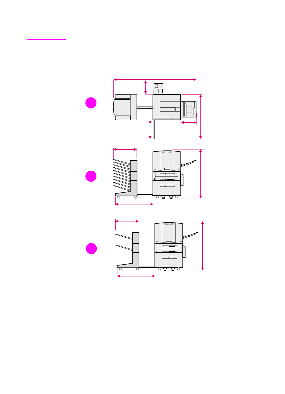
Space requirements
Note See the HP Color LaserJet 8550 MFP printer service manual for space
requirements for the copy module, automatic document feeder, and
1,000-sheet input paper deck.
1404 mm
55 in
290 mm
11 in
1
1085 mm
43 in
363 mm
14 in
1230 mm
48 in
2
495 mm
20 in
838 mm
33 in
460 mm
18 in
495 mm
20 in
1230 mm
3
838 mm
33 in
48 in
Figure 1. Space requirements
1 Top view (with an optional 2,000 -sheet input tray and an optional
multi-bin mailbox, 3,000-sheet stapler/stacker, or 3,000-sheet
stacker)
2 Fr on t v iew (with an optional 2,000-sheet input tray and an
optional multi-bin mailbox)
3 Fr on t v iew (with an optional 2,000-sheet input tray and an
optional 3,000-sheet stapler/stacker or 3,000-sheet stacker)
28 Chapter 1 - Product information EN
Page 31

Media requirements
Selecting media
Many types of paper and other print media can be used with the
printer, within certain specificatio ns.
CAUTION Using media that do not meet the specifications outlined in this chapter
can increase the incidence of media jams, contribute to repair and
maintenance costs, and cause premature wear , print quality problems ,
and problems requiring service. This service might not be covered by
the HP warranty or service agreements.
Before purchasing media or specializ ed f orms, test a small quantity in
the printer. Make sure your media supplier obtains and understands
the media specifications in the HP LaserJet Printer Family Paper
Specification Guide. For ordering information, see page 514.
Note It is possible that media could meet all of the specifications in this
chapter and still not print satisfactorily. This might be caused by
abnormal characteristics of the printing environment, such as e xtremes
in temperature and humidity.
For complete media specifications, see the HP LaserJet Printer
Family Paper Specification Guide.
Use only print media that meet the specifications outlined in this
chapter.
Do not try to print unsupported sizes or weights of media or other
unsupported media.
Always handle tr ansparencies and glossy media by their edges to
avoid fingerprints in the image area.
Adhesives on any media must b e compatible with the printer’s
fusing temperatures (approximately 190° C, or 374° F).
Do not use media that ha v e already p assed through t he printer or
through a copy machine (e v en if there is no printing on the page),
unless you use the “manual print second side” feature.
Recycled media can be used with this printer. Recycled media
must meet the specifications described in this chapter.
EN Media requirements 29
Page 32

Storing media
Follow these guidelines when stacking and storing media:
Leave media in the wrapper until you are ready to use it.
Rewrap partially used packages of media before storing.
Stack cartons upright and squarely on top of each other.
Store envelopes in a protective box to avoid damaging the
envelope edges.
Keep stored media away from temperature and humidity
extremes.
Do not store cartons or reams directly on the floor where they will
absorb humidity. Instead, place cartons on a pallet or on shelves.
Do not store individual reams in any manner that causes them to
curl or warp along the edges.
Do not stack more than six cartons on top of each other.
Do not place anything on top of media (except for stacking
cartons of media), regardless of whether the media is packaged
or unpackaged.
When storing printed documents:
Do not store printed documents in vinyl folders.
Do not expose printed documents to petroleum-based solvents.
30 Chapter 1 - Product information EN
Page 33

Media capacity and sizes for input trays
The following table lists the types and sizes of media supported by
each input tray. For best results, use HP LaserJet paper or
conventional whit e copier paper. The media should be of good quality
and free of cuts, nicks, tears, spots, loose particles, dust, wrinkles,
voids, perforations, and curled or bent edges. For a complete list of
media specifications, see the HP LaserJet Printer Family Paper
Specification Guide.
Table 8. Media capacity and sizes for input trays
Media size and
Tray Media type
Paper
Plain
Preprinted
Letterhead
Prepunched
Bond
Recycled
Color
Card stock
Heavy (more than
28 lb, 105 g/m
Glossy
Tray 1
Envelopes B5 (portrait)
Labels A4 (landscape)
Transparencies A4 (landscape)
*A3 full-bleed is not supported by any of the HP CLJ 8500 or 8550 models.
orientation Media weight
11 by 17 inch (portrait)
JIS B4 (portrait)
A3 (portrait)*
A4 (portrait)
A5 (portrait)
Custom minimum (99 by
190 mm, 3.90 by 7.49
in) (portrait)
Custom maximum (304
by 469 mm, 12 by
2
18.5 inch) (portrait)
)
Executive (portrait)
ISO B5 (portrait)
JIS B4 (portrait)
JIS B5 (portrait)
Letter (landscape)
Legal (landscape)
C5 (portrait)
Commercial #10
(Com10) (portrait)
DL (portrait)
Double Post Card
(JPOSTD)
Monarch (portrait)
Letter (landscape)
Letter (landscape)
16 to 58 lb
(60 to 216 grams per
square meter [g/m
bond
Maximum 24 lb
(90 g/m
— Limit to media-fill mark
5 mils (0.13 mm) thick Limit to media-fill mark
2
) bond
Maximum
capacity
100 sheets of 20 lb
2
])
Limit to media-fill mark
on the media width
guides.
Approximately 10
Limit to media-fill mark
on the media width
guides.
on the media width
guides.
on the media width
guides.
(75 g/m
2
) bond
EN Media requirements 31
Page 34
Table 8. Media capacity and sizes for input trays (continued)
Media size and
Tray Media type
Paper
Plain
Preprinted
Letterhead
Prepunched
Bond
Recycled
Color
Tray 2
Glossy
Transparency A4 (portrait)
Paper
Plain
Preprinted
Letterhead
Prepunched
Bond
Recycled
Color
Tray 3
Glossy
Transparency A4 (portrait)
Paper
Plain
Preprinted
Letterhead
Prepunched
Bond
Recycled
Color
Glossy
orientation Media weight
A4 (landscape)
JIS B4 (portrait)
Letter (landscape)
Legal (portrait)
Letter (portrait)
11 by 17 in (portrait)
A3 (portrait)*
A4 (landscape)
JIS B4 (portrait)
Legal (portrait)
Letter (landscape)
Letter (portrait)
11 by 17 in (portrait)
A4 (landscape)
JIS B4 (portrait)
Legal (portrait)
Letter (landscape)
16 to 28 lb
(60 to 105 g/m
5 mils (0.13 mm) thick Limit to media-fill mark
16 to 28 lb
(60 to 105 g/m
5 mils (0.13 mm) thick Limit to media-fill mark
16 to 28 lb
(60 to 105 g/m
2
2
2
) bond
) bond
) bond
2,000-sheet input tray
*A3 full-bleed is not supported by any of the HP CLJ 8500 or 8550 models.
Maximum
capacity
500 sheets of
20 lb (75 g/m2) bond
Limit to media-fill mark
on the media width
guides.
on the media width
guides.
500 sheets of
20 lb (75 g/m2) bond
Limit to media-fill mark
on the media width
guides.
on the media width
guides.
2,000 sheets of
20 lb (75 g/m2) bond
Limit to media-fill mark
on the media width
guides.
32 Chapter 1 - Product information EN
Page 35

Media capacity and sizes for the multi-bin
mailbox
The following table lists the types and sizes of media supported by
multi-bin mailbox output bins.
Table 9. Media capacity and sizes for the multi-bin mailbox
Bins Media type Media size M edia weight
Paper
Plain
Preprinted
Letterhead
Prepunched
Bond
Mailboxes
Recycled
Color
Paper
Plain
Preprinted
Letterhead
Prepunched
Bond
Recycled
Color
Card Stock
Heavy (more
than 28 lb,
2
105 g/m
Glossy
Labels A4
Transparency A4
)
Left (face-up) output bin
Envelopes B5
*A3 full-bleed is not supported by any of the HP CLJ 8500 or 8550 models.
11 by 17 in
A3*
A4
JIS B4
Legal
Letter
11 by 17 in
A3*
A4
A5
Custom minimum (99 by
190 mm, 3.90 by 7.49
inch)
Custom maximum (304
by 469 mm, 11.98 by
18.48 inch)
Executive
JIS B4
JIS B5
Legal
Letter
Letter
Letter
C5
Commercial #10
(Com10)
DL
Double Post Card
(JPOSTD)
Monarch
16 to 28 lb
(60 to 105 g/m
16 to 58 lb
(60 to 216 g/m
——
5 mils (0.13 mm) thick —
Maximum 24 lb (90 g/
2
m
) bond
2
) bond
2
) bond
Maximum
capacity
250 sheets of 20 lb
(75 g/m2) bond
125 sheets of 20 lb
(75 g/m2) bond
30 Monarch-sized
envelopes
EN Media requirements 33
Page 36

Printable area
Print areas shown in the table below are defined as follows:
Non-masked area—the maximum area in which image signals
are not masked by the compulsory formation of blank image area
(this is the maximum area that can be addressed by the laser
beam).
Recommended print area—the maximum area in which image
signals can be printed on media without any loss of image
signals, excluding manual feed.
Image assurance area—the maximum ar ea in which print quality
can be assured, including manual feed.
Table 10. Printable area specification
Margin
Media type
Non-masked print
area
Cut sheet
Envelope
Recommended
print area
Cut sheet
Envelope
Image assurance
area
Cut sheet
Envelope
Top Bottom Left Right
2.1 mm
(0.083 inch)
2.1 mm
(0.083 inch)
3.0 mm
(0.118 inch)
8.0 mm
(0.315 inch)
6.0 mm
(0.236 inch)
15.0 mm
(0.591 inch)
2.9 mm
(0.114 inch)
2.6 mm
(0.102 inch)
6.0 mm
(0.236 inch)
10.5 mm
(0.413 inch)
6.0 mm
(0.236 inch)
15.0 mm
(0.591 inch)
3.2 mm
(0.126 inch)
3.3 mm
(0.130 inch)
4.0 mm
(0.157 inch)
8.5 mm
(0.335 inch)
5.0 mm
(0.197 inch)
15.0 mm
(0.591 inch)
3.7 mm
(0.146 inch)
3.5 mm
(0.138 inch)
4.5 mm
(0.177 inch)
9.5 mm
(0.374 inch)
5.0 mm
(0.197 inch)
15.0 mm
(0.591 inch)
34 Chapter 1 - Product information EN
Page 37

Media considerations
Note Not all media types are supported in all modes.
Media for duplexer
The duplexer accepts standard-sized media as large as A3 media.
The duplexer accepts up to 28 lb (105 g/m
2
) bond.
Envelopes
The Envelope med ia-type setting in the printer driver has been
optimized for the best print adhesion for most envelop es.
The Heavy Paper mode might also work well for some
envelopes, especially if the printing environment humidity is low.
Use the left (face-up) output bin to reduce curl.
Envelopes with more than on e flap can wrinkle, crease, and
cause jams.
CAUTION To prevent severe printer damage, envelopes with peel-off adhesive
strips must use adhesives compatible with t he printer’s fusing
temperatures (approximately 190° C or 374° F).
Transparencies
The default output for all transparencies is the top output bin for
all HP Color LaserJet 8550 printer models.
The printer’s internal color settings are optimized for the best
color quality if Transparency is selected as the media type in the
printer driver. Using other media type settings will result in less
accurate colors.
The printer only supports transparencies of 5 mils (0.13 mm) in
thickness.
To prevent damage to the printer, transparencies must be able to
withstand the printer’s fusing temperature (approximately 190° C
or 374° F).
Handle transparencies by th e edges . Oil f rom y o ur fingers can be
deposited on the transparencies, causing print quality problems.
Allow printed transparencies to cool before handling to prevent
curling.
WARNING! Allow transparencies to cool before handling to prevent burns.
EN Media requirements 35
Page 38

Glossy media
If you want th e eff ect of glossy media, use only HP LaserJet soft gloss
media in this printer. HP soft gloss is the only glossy media
supported by the printer. For ordering information, see page 513.
Heavy paper stock
Heavy paper stock is an y pap er f rom 28 lb t o 58 lb (1 05 to 216 g/ m2).
Always print hea vy paper stoc k f rom tra y 1. In the printer driv er , select
Heavy Paper or Cardstock as the paper type on the paper tab to
ensure the correct finish on the media. Also, use the left (face-up)
output bin to prevent media jams. For more infor mation about
changing the printer driver settings, see the online help.
Do not use extremely heavy paper stock (greater than 58 lb, or
216 g/m
fusing, poor print quality, and excessive mechanical wear can result.
2
bond). Misfeeds, mis-stacking, media jams, poor toner
Colored media
Colored media should be of the same high quality as white
xerographic paper. Pigments used must be able to withstand the
printer’s fusing temperature (approxim ately 190° C, or 374° F). Do not
use media on which a colored coating was added after production.
The printer cannot detect the color of media you are using. Varying
the shade or color of the media can cha nge th e shades o f the printed
colors.
36 Chapter 1 - Product information EN
Page 39
Media to avoid
To avoid poor print quality or dam age t o the printer, do not use any of
the following:
coated or embossed media
prepunched paper in which the holes were punched 8 mm from
the edge of the pages
media with cutouts or perforations (except prepunched paper)
multi-part forms
media with irregularities, such as tabs or staples
preprinted media with thermography or inks that melt, vaporize,
or release hazardous emissions when subjected to the fusing
temperature (approximately 190° C, or 374° F)
media that produce hazardous emissions , melt, offset, or discolor
when heated to the printer’s fusing temperature (approximately
190° C, or 374° F)
media that have already been through a photocopier or laser
printer (even if there is no printing on the page) unless you use
the “manual print second side” feature.
media with watermarks, if solid fill areas are to be printed
transparencies designed for ink jet printers
any glossy media other than HP soft gloss media
media with texture or finish different from one side to the other
creased or folded media (except for supported envelopes)
EN Media requirements 37
Page 40

Identification (model and serial numbers)
To identify the model number and serial number, find the label located
on the rear of the printer, similar to the one shown in figure 2 (the
example shown is from an HP Color LaserJet 8500 printer).
(serial #)
(model #)
Figure 2. Example of printer model number and serial number label
(110 V and 220 V)
38 Chapter 1 - Product information EN
Page 41
Printer Information
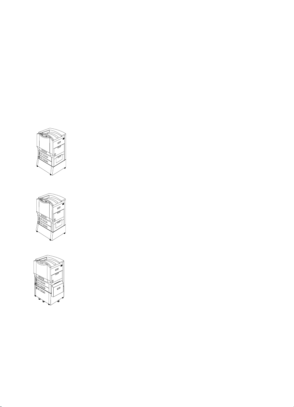
Configurations
Available configurations for the HP Color LaserJet 8500 printer
appear below; available configurations for the HP Color LaserJet
8550 printer are shown on the following page.
The HP Color LaserJet 8500 printer is available in the following
configurations:
HP Color LaserJet 8500
The HP Color LaserJet 8500 comes standard with a 100-sheet tr a y 1,
a 500-sheet tray2, a 500-sheet tray 3, a printer stand, and 32 MB
random-access memory (RAM).
HP Color LaserJet 8500 N
The HP Color LaserJet 8500N comes standard with a 100-sheet
tray 1, a 500-sheet tray 2, a 500-sheet tray 3, a printer stand, 32 MB
RAM, an HP JetDirect print server (10/100 Base-TX), and an inte rnal
hard disk.
HP Color LaserJet 8500 DN
The HP Color LaserJet 8500DN comes standard with a 100-sheet
tray 1, a 500-she et tray 2, a 500- sheet tray 3, a (tray 4) 2000-sheet
input tray, a duplexer, 64 MB RAM, an HP JetDirect print server (10/
100 Base-TX), an internal hard disk, and five stabilizing legs.
EN Printer Information 39
Page 42

The HP Color LaserJet 8550 printer is available in the following
configurations:
HP Color LaserJet 8550
The HP Color LaserJet 8550 comes standard with a 100-sheet tr a y 1,
a 500-sheet tray3, a printer stand, and 32 MB RAM.
HP Color LaserJet 8550 N
The HP Color LaserJet 8550N comes standard with a 100-sheet
tray 1, a 500-sheet tray 2, a 500-sheet tray 3, a printer stand, 64 MB
RAM, an HP JetDirect print server (10/100 Base-TX), and an inte rnal
hard disk.
HP Color LaserJet 8550 DN
The HP Color LaserJet 8550DN comes standard with a 100-sheet
tray 1, a 500-she et tray 2, a 500- sheet tray 3, a (tray 4) 2000-sheet
input tray, a duplexer, 64 MB RAM, an HP JetDirect print server (10/
100 Base-TX), an internal hard disk, and five stabilizing legs.
HP Color LaserJet 8550 GN
The HP Color LaserJet 8550GN comes standard with a 100-sheet
tray 1, a 500-she et tray 2, a 500- sheet tray 3, a (tray 4) 2000-sheet
input tray, a duplexer, 128 MB RAM, an HP JetDirect print server (10/
100 Base-TX), an internal hard disk, five stabilizing legs, and a highperformance processor.
HP Color LaserJet 8550 MFP
The HP Color LaserJet 8550MFP comes standard with a 100-sheet
tray 1, a 500-sheet tr a y 2, a 500-she et tra y 3, a duple x er , 64 M B RAM,
an HP JetDirect print server (10/100 Base-TX), an internal hard disk,
a printer/copy module stand, and a copy module.
40 Chapter 1 - Product information EN
Page 43

External views
1
2
3
4
5
6
Figure 3. Front view
7
8
9
10
11
12
1 Printer control panel (see
page 80)
2 Left (face-up) output bin
3 Front door handle
4 Input tray 2 (not included on
the HP Color LaserJet 8550
base model, but available as
an option)
5 Power/standby button
6 Input tray 3
Note The power/standby button shown above is immobilized in HP Color
LaserJet 8550 MFP printers. Use the power button at the top, right of
the copy module after plugging the printer power cable into the right
side of the copy module. See the HP Color LaserJet 8550 MFP printer
user guide for more information.
EN Printer Information 41
7 Top (face-down) output bin
8 Flip-up media stop (HP Color
LaserJet 8500 models only)
9 Right upper cover
10 Input tray 1
11 Right lower cover
12 Printer stand (base unit and
N models only)
Page 44

3
1
2
Figure 4. Rear view
1 Air filter door
2 Formatter tray
3 Left upper cover
4 Left lower cover
5 Power connector
4
5
42 Chapter 1 - Product information EN
Page 45
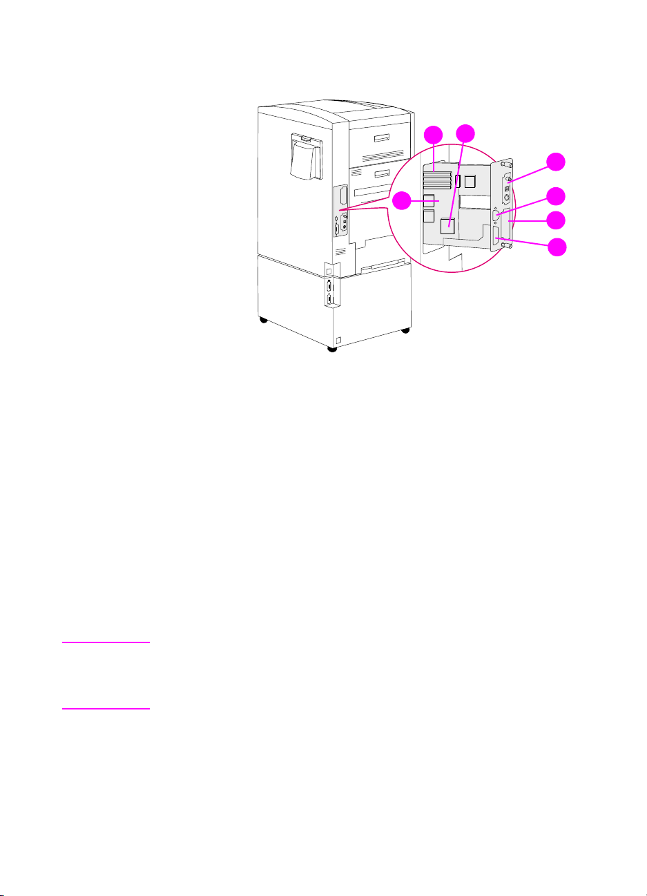
Formatter assemblies
3
2
4
Figure 5. Formatter assemblies
1 Formatter board
2 DIMM slots
3 Printer hard disk location (factory-installed on HP Color LaserJet
8500 N, 8500 DN, 8550 N, 8550 DN, 8550 GN, and 8550 MFP
models)
4 EIO slot 2 (shown with HP JetDirect internal print server)
5 Parallel IEEE-1284 interface port (C-size)
6 EIO slot 1
7 C-link connector
1
5
6
7
7
Note Either EIO slot can have a hard disk installe d if there is not a factory-
installed internal hard drive mounted on the f ormatter board. Howe ver ,
the printer does not support two hard disks; the printer can support one
hard disk at a time—either internal or external.
EN Printer Information 43
Page 46

Media-handling accessories and options
1
2
3
4
5
6
7
8
Figure 6. Media-handling accessories and options
1 Multi-bin mailbox
2 Multi-bin mailbox status light
3 Duplexer (internal)
4 Tra y 2
9
5 2,000-sheet input tray (tray 4) (only available on 8500 DN,
8550 DN, and 8550 GN models)
6 Tray 4 status light
7 Med i a transfer door (attache d to tray 4)
8 3,000-sheet stapler/stacker or 3,000-sheet stacker (only
compatible with 8550 DN and 8550 GN models)
9 3,000-sheet stapler/stacker or 3,000-sheet stacker status light
44 Chapter 1 - Product information EN
Page 47

Table 11. Paper handling accessory status LEDs
2,000-sheet input
LED
unit Multi-bin mailbox Stapler/stacker
Flashing amber The accessory has a
media jam or a page
needs to be removed
from the 2,000-sheet
input unit, even if the
page is not jammed.
The vertical transfer
unit (VTU) might be
open.
Solid amber The accessory is experiencing a hardware malfunction.
Solid green The accessory is on and ready.
Off
The printer might be in Power Save mode. Press
The accessory is not receiving power. Check both the power supply and
the power cables.
The accessory has a
media jam or a page
needs to be removed
from the multi-bin
mailbox, even if the
page is not jammed.
The accessory is not
correctly attached to
the printer.
The accessory has a
media jam or a staple
jam, or one or more
bins are full.
The accessory is not
correctly attached to
the printer.
GO.
EN Printer Information 45
Page 48

Safety information
FCC regulations
This equipment has been tested and found to comply with the limits
for a Class B digital device, pursuant to Part 15 of the U.S. Federal
Communications Commission (FCC) rules. These limit s are designed
to provide reasonable protection against harmful interference in a
residential installation. This equipment generat es, uses, and can
radiate radio frequency energy, and if not installed and used in
accordance with the instructions, may cause harmful interference to
radio communications. However, there is no gua rantee that
interference will not occur in a particular installation. If this equipment
does cause harmful interference to radio or television reception,
which can be determined by turning the equipment off and on, the
user is encouraged to try to correct the interference by one or more of
the following measures:
Reorient or relocate the receiving antenna.
Increase separation between equipment and receiver.
Connect equipment to an outlet on a circuit different from that on
which the receiver is located.
Consult your dealer or an experienced radio/television technician.
Note Any changes or modifications to the printer no t expre ssly approv ed by
HP could void the user’s authority to operate this equipment.
Use of a shielded interface cable is required to comply with the FCC
rules.
Canadian DOC regulations
Complies with Canadian EMC Class B requirements.
«Conforme á la classe B des normes canadiennes de compatibilité
électromagnétiques. «CEM».»
46 Chapter 1 - Product information EN
Page 49

Declarations of conformity
DOC—HP Color LaserJet 8500 printer
DECLARATION OF CONFORMITY
according to ISO/IEC Guide 22 and EN 45014
Manufacturer’s Name:
Manufacturer’s Address:
declares, that the product
Product Name:
Model Number:
Product Options:
conforms to the following Product Specifications:
Safety: IEC 950:1991+A1+A2+A3+A4 / EN 60950:1992+A1+A2+A3+A4
IEC 825-1:1993 / EN 60825-1:1994 Class 1 (Laser/LED)
EMC: CISPR 22:1993+A1 / EN 55022:1994 Class B
CISPR 22:1993+A1 / EN 55022:1994 Class A*
EN 5081-1:1992
EN 50082-1:1992
IEC 801-2:1991 / prEN 55024-2:1992 -4 kV CD, 8 kV AD
IEC 801-3:1984 / prEN 55024-3:1991 -3 V/m
IEC 801-4:1988 / prEN 55024-4:1992 -0.5 kV Signal Lines
1.0 kV Power Lines
FCC Title 47 CFR, Part 15 Class B
AS / NZS 3548:1992 / CISPR 22:1993 Class
Supplementary Information:
Hewlett-Packard Company
11311 Chinden Boulevard
Boise, Idaho 83714-1021, USA
HP Color LaserJet 8500, 8500 N, 8500 DN
C3983A, C3984A, C3985A
ALL
1
2
/ICES-003, Issue 2/VCCI-2
1
1
The product herewith complies with the requirements of the following Directives and carries the CEmarking accordingly:
- the EMC directive 89/336/EEC
- the Low Voltage Directive 73/23/EEC
1
The product was tested in a typical configuration with Hewlett-Packard Personal Computer Systems.
2
This Device complies with Part 15 of the FCC rules. Operation is subject to the following two conditions:
(1) this device may not cause harmful interference, and (2) this device must accept any interference
received, including interference that may cause undesired operation.
* This printer contains Local Area Network (LAN) options. When the interface cable is attached to either of
the IEEE 802.3 connectors, the printer meets the requirements of EN55022 Class A.
February 12, 1997
For Compliance Information ONLY, contact:
Australia Contact: Product Regulations Manager, Hewlett-Packard Australia Ltd., 31-41 Joseph
Street, Blackburn, Victoria 3130, Australia
Europe Contact: A Local Hew lett-Packard Sales and Service Office or Hewlett-Packard GmbH,
Department HQ-TRE / Standards Europe, Herrenberger Strasse 130, D-71034
Böblingen (Fax: +49-7031-14-3143)
USA Contact: Product Regulations Manager, Hewlett-Packard Company, P.O. Box 15 Mail Stop
160, Boise, ID 83707-0015 (Phone: 208-396-6000)
EN Safety information 47
Page 50

DOC—HP Color LaserJet 8550 printer
DECLARATION OF CONFORMITY
according to ISO/IEC Guide 22 and EN 45014
Manufacturer’s Name:
Manufacturer’s Address:
declares, that the product
Product Name:
Model Number:
Product Options:
conforms to the following Product Specifications:
Safety: IEC 950:1991+A1+A2+A3+A4 / EN
60950:1992+A1+A2+A3+A4+A11
IEC 825-1:1993 / EN 60825-1:1994+A11 Class 1 (Laser/LED)
EMC: CISPR 22:1997 / EN 55022:1998 Class A
EN 61000-3-2:1995
EN 61000-3-3:1995
EN 55024:1998
FCC Title 47 CFR, Part 15 Class A
AS / NZS 3548:1995
Supplementary Information:
The product herewith complies with the requirements of the following EMC Directive 89/336/EEC and the
Low Voltage Directive 73/23/EEC, and carries the CE-Marking accordingly.
1
The product was tested in a typical configuration with Hewlett-Packard Personal Computer Systems.
2
This Device complies with Part 15 of the FCC rules. Operation is subject to the following two conditions:
(1) this device may not cause harmful interference, and (2) this device must accept any interference
received, including interference that may cause undesired operation.
Hewlett-Packard Company
11311 Chinden Boulevard
Boise, Idaho 83714-1021, USA
HP Color LaserJet 8550, 8550 N, 8550 DN, 8550
GN, 8550 MFP
C7096A, C7097A, C7098A, C7099A, C7835A,
C7836A
ALL
1
2
1
/ ICES-002
1
WARNING! This is a Class A product. In a domestic environment this product may cause radio
interference in which case the user may be required to take adequate measures.
Boise, Idaho USA
May 1999
For regulatory topics only:
Australia Contact: Product Regulations Manager, Hewlett-Packard Australia Ltd., 31-41 Joseph
Street, Blackburn, Victoria 3130, Australia
Europe Contact: A Local Hew lett-Packard Sales and Service Office or Hewlett-Packard GmbH,
Department HQ-TRE / Standards Europe, Herrenberger Strasse 130, D-71034
Böblingen (Fax: +49-7031-14-3143)
USA Contact: Product Regulations Manager, Hewlett-Packard Company, P.O. Box 15 Mail Stop
160, Boise, ID 83707-0015 (Phone: 208-396-6000)
48 Chapter 1 - Product information EN
Page 51

DOC—Duplexer
DECLARATION OF CONFORMITY
according to ISO/IEC Guide 22 and EN 45014
Manufacturer’s Name:
Manufacturer’s Address:
declares, that the product
Product Name:
Model Number:
Product Options:
conforms to the following Product Specifications:
EMC: CISPR 22:1993+A1 / EN 55022:1994 Class B
CISPR 22:1993+A1 / EN 55022:1994
EN 50081-1:1992
EN 50082-1:1992
IEC 801-2:1991 / prEN 55024-2:1992 -4 kV CD, 8 kV AD
IEC 801-3:1984 / prEN 55024-3:1991 -3 V/m
IEC 801-4:1988 / prEN 55024-4:1992 -0.5 kV Signal Lines
FCC Title 47 CFR, Part 15 Class B
AS / NZS 3548:1992 / CISPR 22:1993 Class B
Supplementary Information:
The product herewith complies with the requirements of the following Directives and carries the CEmarking accordingly:
- the EMC directive 89/336/EEC
- the Low Voltage Directive 73/23/EEC
1
The product was tested in a typical configuration with Hewlett-Packard Personal Computer Systems.
2
This Device complies with Part 15 of the FCC rules. Operation is subject to the following two conditions:
(1) this device may not cause harmful interference, and (2) this device must accept any interference
received, including interference that may cause undesired operation.
July 16, 1997
For Compliance Information ONLY, contact:
Australia Contact: Product Regulations Manager, Hewlett-Packard Australia Ltd., 31-41 Joseph
Street, Blackburn, Victoria 3130, Australia
Hewlett-Packard Company
Montemorelos 299
Guadalajara Jalisco, 45060
México
Duplexer
C4782A
N/A
1
2
/ICES-003, Issue 2/VCCI-2
1
1.0 kV Power Lines
1
Europe Contact: A Local Hewlett-Packard Sales and Service Office or Hewlett-Packard GmbH,
Department HQ-TRE / Standards Europe, Herrenberger Strasse 130, D-71034
Böblingen (Fax: +49-7031-14-3143)
USA Contact: Product Regulations Manager, Hewlett-Packard Company, P.O. Box 15 Mail
Stop 160, Boise, ID 83707-0015 (Phone: 208-396-6000)
EN Safety information 49
Page 52

DOC—2,000-sheet input tray
DECLARATION OF CONFORMITY
according to ISO/IEC Guide 22 and EN 45014
Manufacturer’s Name:
Manufacturer’s Address:
declares, that the product
Product Name:
Model Number:
Product Options:
conforms to the following Product Specifications:
Safety: IEC 950:1991+A1+A2+A3+A4 / EN
60950:1992+A1+A2+A3+A4
IEC 825-1:1993 / EN 60825-1:1994 Class 1 (Laser/LED)
EMC: CISPR 22:1993+A1 / EN 55022:1994 Class B
CISPR 22:1993+A1 / EN 55022:1994
EN 50081-1:1992
EN 50082-1:1992
IEC 801-2:1991 / prEN 55024-2:1992 -4 kV CD, 8 kV AD
IEC 801-3:1984 / prEN 55024-3:1991 -3 V/m
IEC 801-4:1988 / prEN 55024-4:1992 -0.5 kV Signal Lines
1.0 kV Power Lines
FCC Title 47 CFR, Part 15 Class B
AS / NZS 3548:1992 / CISPR 22:1993 Class B
Supplementary Information:
The product herewith complies with the requirements of the following Directives and carries the CEmarking accordingly:
- the EMC directive 89/336/EEC
- the Low Voltage Directive 73/23/EEC
1
The product was tested in a typical configuration with Hewlett-Packard Personal Computer Systems.
2
This Device complies with Part 15 of the FCC rules. Operation is subject to the following two conditions:
(1) this device may not cause harmful interference, and (2) this device must accept any interference
received, including interference that may cause undesired operation.
July 16, 1997
For Compliance Information ONLY, contact:
Australia Contact: Product Regulations Manager, Hewlett-Packard Australia Ltd.,
31-41 Joseph Street, Blackburn, Victoria 3130, Australia
Europe Contact: A Local Hewlett-Packard Sales and Service Office or Hewlett-Packard GmbH,
Department HQ-TRE / Standards Europe, Herrenberger Strasse 130,
D-71034 Böblingen (Fax: +49-7031-14-3143)
USA Contact: Product Regulations Manager, Hewlett-Packard Company,
P.O. Box 15 Mail Stop 160, Boise, ID 83707-0015 (Phone: 208-396-6000)
Hewlett-Packard Company
Montemorelos 299
Guadalajara Jalisco, 45060
México
2,000-Sheet Input Tray
C4781A
N/A
1
2
/ICES-003, Issue 2/VCCI-2
1
1
50 Chapter 1 - Product information EN
Page 53

DOC—Multi-bin mailbox
DECLARATION OF CONFORMITY
according to ISO/IEC Guide 22 and EN 45014
Manufacturer’s Name:
Manufacturer’s Address:
declares, that the product
Product Name:
Model Number:
Product Options:
is in conformity with:
EMC: CISPR 22:1993+A1 / EN 55022:1994 Class B
EN 50082-1:1992
IEC 801-2:1991 / prEN 55024-2:1992 -4 Kv CD, 8 kV AD
IEC 801-3:1984 / prEN 55024-3:1991 -3 V/m
IEC 801-4:1988 / prEN 55024-4:1992 -0.5 kV Signal Lines
FCC Title 47 CFR, Part 15 Class B
AS / NZS 3548:1992 / CISPR 22:1993 Class B
Safety: IEC 950:1991+A1+A2+A3 / EN 60950:1992+A1+A2+A3
IEC 825-1:1993 / EN 60825-1:1994 Class 1 (Laser/LED)
Telecom N/A
Additional Information:
The product herewith complies with the requirements of the following Directives and carries the CEmarking accordingly:
EMC the EMC directive 89/336/EEC
Safety the Low Voltage Directive 73/23/EEC
Quality System This product was manufactured under a formal quality system.
1
The product was tested in a typical configuration with Hewlett-Packard Personal Computer Systems.
2
This Device complies with Part 15 of the FCC rules. Operation is subject to the following two conditions:
(1) this device may not cause harmful interference, and (2) this device must accept any interference
received, including interference that may cause undesired operation.
April 29, 2998
For Compliance Information ONLY, contact:
Australia Contact: Product Regulations Manager, Hewlett-Packard Australia Ltd.,
31-41 Joseph Street, Blackburn, Victoria 3130, Australia
Europe Contact: A Local Hewlett-Packard Sales and Service Office or Hewlett-Packard GmbH,
Department HQ-TRE / Standards Europe, Herrenberger Strasse 130,
D-71034 Böblingen (Fax: +49-7031-14-3143)
USA Contact: Product Regulations Manager, Hewlett-Packard Company,
P.O. Box 15 Mail Stop 160, Boise, ID 83707-0015 (Phone: 208-396-6000)
Hewlett-Packard Company
Montemorelos 299
Guadalajara Jalisco, 45060
México
Multi-bin Mailbox
C4785A, C4240A
N/A
1
2
/ ICES-003, Issue 2/VCCI-B
1.0 kV Power Lines
1
1
EN Safety information 51
Page 54

DOC—3,000-sheet stapler/stacker
DECLARATION OF CONFORMITY
according to ISO/IEC Guide 22 and EN 45014
Manufacturer’s Name:
Manufacturer’s Address:
declares, that the product
Product Name:
Model Number:
Product Options:
is in conformity with:
EMC: CISPR 22:1993+A1+A2 / EN 55022:1994+A1+A23 Class B
EN 50082-1:1992
IEC 801-2:1991 / prEN 55024-2:1992 -4 Kv CD, 8 kV AD
IEC 801-3:1984 / prEN 55024-3:1991 -3 V/m
IEC 801-4:1988 / prEN 55024-4:1992 -0.5 kV Signal Lines
FCC Title 47 CFR, Part 15 Class B
AS / NZS 3548:1992 / CISPR 22:1993 Class B
Safety: IEC 950:1991+A1+A2+A3+A4+A11 / EN 60950:1992+A1+A2+A3+A4+A11
IEC 825-1:1993 / EN 60825-1:1994 Class 1 (Laser/LED)
UL1950, Third Edition
Additional Information:
The product herewith complies with the requirements of the following Directives and carries the CEmarking accordingly:
EMC the EMC directive 89/336/EEC
Safety the Low Voltage Directive 73/23/EEC
1
The product was tested in a typical configuration with Hewlett-Packard Personal Computer Systems.
2
This Device complies with Part 15 of the FCC rules. Operation is subject to the following two conditions:
(1) this device may not cause harmful interference, and (2) this device must accept any interference
received, including interference that may cause undesired operation.
Hewlett-Packard Company
Montemorelos 299
Guadalajara Jalisco, 45060
México
3,000-Sheet Stapler/Stacker
C4788A
N/A
2
/ ICES-003, Issue 2/VCCI-B
1.0 kV Power Lines
1
1
1
Quality System This product was manufactured under a formal quality system.
February 10, 1999
For Compliance Information ONLY, contact:
Australia Contact: Product Regulations Manager, Hewlett-Packard Australia Ltd.,
31-41 Joseph Street, Blackburn, Victoria 3130, Australia
Europe Contact: A Local Hewlett-Packard Sales and Service Office or Hewlett-Packard GmbH,
Department HQ-TRE / Standards Europe, Herrenberger Strasse 130,
D-71034 Böblingen (Fax: +49-7031-14-3143)
USA Contact: Product Regulations Manager, Hewlett-Packard Company,
P.O. Box 15 Mail Stop 160, Boise, ID 83707-0015 (Phone: 208-396-6000)
52 Chapter 1 - Product information EN
Page 55

DOC—3,000-sheet stacker
DECLARATION OF CONFORMITY
according to ISO/IEC Guide 22 and EN 45014
Manufacturer’s Name:
Manufacturer’s Address:
declares, that the product
Product Name:
Model Number:
Product Options:
is in conformity with:
EMC: CISPR 22:1993+A1+A2 / EN 55022:1994+A1+A23 Class B
EN 50082-1:1992
FCC Title 47 CFR, Part 15 Class B
AS / NZS 3548:1992 / CISPR 22:1993 Class B
Safety: IEC 950:1991+A1+A2+A3+A4+A11 / EN 60950:1992+A1+A2+A3+A4+A11
Additional Information:
The product herewith complies with the requirements of the following Directives and carries the CEmarking accordingly:
EMC the EMC directive 89/336/EEC
Safety the Low Voltage Directive 73/23/EEC
1
The product was tested in a typical configuration with Hewlett-Packard Personal Computer Systems.
2
This Device complies with Part 15 of the FCC rules. Operation is subject to the following two conditions:
(1) this device may not cause harmful interference, and (2) this device must accept any interference
received, including interference that may cause undesired operation.
IEC 825-1:1993 / EN 60825-1:1994 Class 1 (Laser/LED)
UL1950, Third Edition
IEC 801-2:1991 / prEN 55024-2:1992 -4 Kv CD, 8 kV AD
IEC 801-3:1984 / prEN 55024-3:1991 -3 V/m
IEC 801-4:1988 / prEN 55024-4:1992 -0.5 kV Signal Lines
Hewlett-Packard Company
Montemorelos 299
Guadalajara Jalisco, 45060
México
3,000-Sheet Stacker
C4788A
N/A
2
/ ICES-003, Issue 2/VCCI-B
1.0 kV Power Lines
1
1
1
Quality System This product was manufactured under a formal quality system.
February 10, 1999
For Compliance Information ONLY, contact:
Australia Contact: Product Regulations Manager, Hewlett-Packard Australia Ltd.,
31-41 Joseph Street, Blackburn, Victoria 3130, Australia
Europe Contact: A Local Hewlett-Packard Sales and Service Office or Hewlett-Packard GmbH,
Department HQ-TRE / Standards Europe, Herrenberger Strasse 130,
D-71034 Böblingen (Fax: +49-7031-14-3143)
USA Contact: Product Regulations Manager, Hewlett-Packard Company,
P.O. Box 15 Mail Stop 160, Boise, ID 83707-0015 (Phone: 208-396-6000)
Note See the HP Color LaserJet 8550 MFP printer Service Manual for
Declarations of Conformity for the copy module, automatic document
feeder, and 1,000-sheet input paper deck.
EN Safety information 53
Page 56

VCCI statement (Japan)—8500 models
VCCI statement (Japan)—8550 models
EMI statement (Korea)—8500 models
EMI statement (Korea)—8550 models
54 Chapter 1 - Product information EN
Page 57

Laser safety statement
The Center for Devices and Radiological Health (CDRH) of the U.S.
Food and Drug Administration has implemented regulations for laser
products manufacture d since August 1, 1976. Compliance is
mandatory for products marketed in the United States. This printer is
certified as a “Class 1” laser product under the U.S. Department of
Health and Human Services (DHHS) Radiation Performance
Standard according to the Radiat ion Control f or Health and Saf ety Act
of 1968. Because radiation emitted inside this printer is completely
confined within protective housings and external covers, the laser
beam cannot escape during any phase of normal user operation.
EN Safety information 55
Page 58

Laser statement for Finland
Luokan 1 laserlaite
Klass 1 Laser Apparat
HP LaserJet 8500, 8500 N, 8500 DN laserkirjoitin on käyttäjän kannalta turvallinen
luokan 1 laserlaite. Normaalissa käytössä kirjoittimen suojakotelointi estää lasersäteen
pääsyn laitteen ulkopuolelle. Laitteen turvallisuusluokka on määritetty standardin EN
60825-1 (1994) mukaisesti.
Varoitus!
Laitteen käyttäminen muulla kuin käyttöohjeessa mainitulla tavalla saattaa altistaa
käyttäjän turvallisuusluokan 1 ylittävälle näkymättömälle lasersäteilylle.
Varning!
Om apparaten används på annat sätt än i bruksanvisning specificerats, kan
användaren utsättas för osynlig laserstrålning, som överskrider gränsen för laserklass
1.
HUOLTO
HP LaserJet 8500, 8500 N, 8500 DN -kirjoittimen sisällä ei ole käyttäjän huollettavissa
olevia kohteita. Laitteen saa avata ja huoltaa ainoastaan sen huoltamiseen koulutettu
henkilö. Tällaiseksi huoltotoimenpiteeksi ei katsota väriainekasetin vaihtamista,
paperiradan puhdistusta tai muita käyttäjän käsikirjassa lueteltuja, käyttäjän tehtäväksi
tarkoitettuja ylläpitotoimia, jotka voidaan suorittaa ilman erikoistyökaluja.
Varo!
Mikäli kirjoittimen suojakotelo avataan, olet alttiina näkymättömälle lasersäteilylle
laitteen ollessa toiminnassa. Älä katso säteeseen.
Varning!
Om laserprinterns skyddshölje öppnas då apparaten är i funktion, utsättas användaren
för osynlig laserstrålning. Betrakta ej strålen.
Tiedot laitteessa käytettävän laserdiodin säteilyominaisuuksista:
Aallonpituus 775-795 nm
Teho 5 mW
Luokan 3B laser
56 Chapter 1 - Product information EN
Page 59

Product information sheet
The Toner Product Information Sheet can be view ed on the World
Wide Web at the following URL:
http://www.hp.com
Click “Search” and enter “Toner Product Information Sheet” where
appropriate.
International customers should see page 66 for appropriate phone
numbers and information.
Toner safety
Toner is composed of plastic and a small amount of pigment. Avoid
breathing toner particles; toner might be harmful to your health. T oner
can also stain clothing. Skin and clothing are best cleaned by
removing as much toner as possible with a dry tissue, then washing
with cold water . Hot water causes toner to melt and permanently fuse
into clothing.
Material Safety Data Sheet (MSDS)
The Toner Cartridge/Drum MSDS can be viewed on the World Wide
Web at the following URL:
http://www.hp.com
Click “Search” and enter “MSDS” where appropriate.
International customers should see page 66 for appropriate phone
numbers and information.
EN Safety information 57
Page 60

Ozone safety
Ozone emission
The corona assemblies f ound in laser printers and photocopiers
generate ozone gas (O
process. Ozone is generated only while the printer is printing (while
the coronas are energized).
This HP LaserJet printer contains an charcoal filter to protect office
air quality. See page 119 for suggested replacement intervals.
Ozone standards
Standards for exposure to ozone have been established by the
Department of Labor—Occupational Safety and Health
Administration (DOL-OSHA) and the American Conference of
Governmental Industrial Hygienists (ACGIH). These standards are
0.1 parts per million as a time-weighted average and a ceiling limit
respectively. All HP LaserJet family printers meet these standards
when shipped from the factory.
Recommendations for minimizing ozone exposure
Some people are extremely sensitive to ozone. In such cases, it is
advisable to position the printer away from the sensitive user. Also, a
more frequent filter replacement might be necessary.
) as a by-product of the electrophotographic
3
Almost all ozone concerns arise from abnormal site or operating
conditions. The fo llowing conditions might generate an ozone
complaint:
installation of multiple laser printers in a confined area
extremely low relative humidity
poor room ventilation
directing the exhaust port of the printer towards the face of
personnel
poor conditions of the existing ozone filter
long, continuous printing combined with any of t he above
Inspect your work environment for the operating conditions listed
above if you believe ozone emissions are a problem in your area.
(Your employ er is responsible f or providing a work envir onment that is
free of these conditions.)
58 Chapter 1 - Product information EN
Page 61

2Service approach
Chapter contents
Introduction . . . . . . . . . . . . . . . . . . . . . . . . . . . . . . . . . . . . . . 61
Parts and supplies. . . . . . . . . . . . . . . . . . . . . . . . . . . . . . . . . 61
Ordering . . . . . . . . . . . . . . . . . . . . . . . . . . . . . . . . . . . . . . . . 62
Obtaining related documentation and software. . . . . . 62
Ordering consumables. . . . . . . . . . . . . . . . . . . . . . . . . 62
Ordering field-replaceable units. . . . . . . . . . . . . . . . . . 63
Parts exchange program . . . . . . . . . . . . . . . . . . . . . . . 63
Technical assistance . . . . . . . . . . . . . . . . . . . . . . . . . . . . . . . 64
List Server . . . . . . . . . . . . . . . . . . . . . . . . . . . . . . . . . . 64
HP ASAP. . . . . . . . . . . . . . . . . . . . . . . . . . . . . . . . . . . 64
Dealer Response Line. . . . . . . . . . . . . . . . . . . . . . . . . 65
HP Software Distribution Center . . . . . . . . . . . . . . . . . 66
HP Direct . . . . . . . . . . . . . . . . . . . . . . . . . . . . . . . . . . . 66
Parts identification . . . . . . . . . . . . . . . . . . . . . . . . . . . . 66
Customer Information Centers. . . . . . . . . . . . . . . . . . . 66
HP Customer Care Centers. . . . . . . . . . . . . . . . . . . . . 67
Warranty . . . . . . . . . . . . . . . . . . . . . . . . . . . . . . . . . . . . . . . . 69
Installation . . . . . . . . . . . . . . . . . . . . . . . . . . . . . . . . . . 69
Toner cartridge information . . . . . . . . . . . . . . . . . . . . . 69
EN Chapter contents 59
Page 62

60 Chapter 2 - Service approach EN
Page 63

Introduction
Repair normally begins with the use of printer internal diagnostics in
conjunction with the troubleshooting procedures in chapter 7.
When repairing an HP Color LaserJet 8550 MFP printer, first isolate
the location of the problem. Usually, simply sending a print job to the
printer from a computer is sufficient to determine whether or not the
print engine is involved. If it is not, see the service manual specific to
the HP Color LaserJet 8550 MFP printe r.
Once a faulty part is located, repair is generally accomplished by
assembly-level replacement of the field-replaceable units. Some
mechanical assemblies can be repaired at the subassembly level.
Parts and supplies
Field replaceable and accessory part numbers are found in chapter 8
of this manual. Use only accessories specifically designed for this
printer. Accessories can be ordered from an authorized service or
support provider. For a list of available accessories and their part
numbers, see page 511. Replacement parts can be ordered from
HP’s Service Materials Organization or Support Materials Europe.
The following tab le list s inf ormation f or ordering fro m SME, SMO , and
HP Distribution Center (HPD).
Table 12. Ordering
Organization Address Phone
SMO (Service Materials
Organization)
SME (Support Materials Europe) Hewlett-Packard Company
HPD (HP Distribution Center) (805) 257-5565
EN Introduction 61
Hewlett-Packard Company
Support Materials Organization
8050 Foothills Blvd.
Roseville, CA 95678
Support Materials Europe
Wolf-Hirth Strasse 33
D-7030 Böblingen, Germany
(1) (800) 227-8164
(U.S. only)
(49 7031) 14-2253
(805) 257-6995 Fax
Page 64
Ordering
Obtaining related documentation and
software
To order related documentation and software , contact SMO or SME at
the numbers listed on the previous page. Part numbers for related
documentation are listed beginning on page 514.
For information through the World Wide Web, visit the following
websites:
Table 13. Technical support websites
HP Customer Care Online
Software drivers, support documentation, and
answers to frequently asked questions
HP Technical Training
(North America)
Classes and schedules
Parts
Parts information
Ordering consumables
Consumable parts and accessories are available dir ectly from
Hewlett-Packard at the following numbers:
U.S.: (1) (800) 538-8787
Canada: (1) (800) 387-3154
(in Toronto: (416) 671-8383)
United Kingdom: 0734-441212
Contact your local HP Parts Coordinator for other local phone
numbers.
To find a dealer near you, call the HP Customer Information Center at
(1) (800) 752-0900.
http://www.hp.com/go/support
http://www.hp.com/go/resellertraining
http://outfield.external.hp.com/spi/welcom.htm
If the local dealer is temporarily out of stock, use one of the numbers
above or call (1) (800) 752-0900 to find another dealer near you.
62 Chapter 2 - Service approach EN
Page 65

Ordering field-replaceable units
This printer is designed to be repaired by replacing field-replaceable
units. Part numbers are located in chapter 8 of this manual and can
be ordered from SMO or SME (see page 62).
Parts exchange program
HP offers remanu fa ctured assemb lies f or som e selected parts. These
are identified in chapter 8 and can be ordered through SMO or SME
(see page 62).
EN Ordering 63
Page 66

Technical assistance
List Server
A list server is an e-mail program that allows users to subscribe to
certain mail lists by sending e-mail to the server. The list server allows
HP LaserJet Technical Marketing to make the support community
aware of new or urgent information by sending information to
subscribers.
To subscribe to hardware-related information, send e-mail to:
subscribe-CLJ8500/8550-HW@chsdes1.boi.hp.com
To subscribe to software-related information, send e-mail to:
subscribe-CLJ8500/8550-SW@chsdes1.boi.hp.com
Once you subscribe, you will receive more information about the
benefits of the list server as well as additional instruction about h ow to
use the list server.
HP ASAP
HPASAP (Automated Support Access Program) provides free
technical support information 24 hours a day, 7 days a week. The
ASAP system includes HP FIRST, explained below. The ASAP
service at (1) (800) 333-1917 (U.S.) requires a touchtone phone.
HP FIRST
HP FIRST (Fax Information Retrieval Support Technology) is a
phone-in fax service providing technical information for HP LaserJet
end-users as well as service pe rs on ne l. Re ceiv ing a fax requires a
type 3 facsimile machine or fax card. Service-related information
includes:
service notes (HP Authorized Dealers)
Product Data Sheets
Material Safety Data Sheets (MSDSs)
typeface and accessory information
printer support software information
toner information
driver request form and Software Matrix
64 Chapter 2 - Service approach EN
Page 67

HP FIRST, U. S.
Call the HPASAP system at (1) (800) 333-1917 and follow the voice
prompts to enter HP FIRST.
HP FIRST, Europe
Call HP FIRST at one of the following numbers:
U.K: 0800-96-02-71
Belgium: 078-111906 (Dutch)
Switzerland: 155-1527 (German)
Netherlands: 06-0222420
Germany: 0130-810061
Austria: 0660-8128
For English-language service outside the countries listed above,
call (31) 20-681-8192.
Dealer Response Line
For further technical assistance on pre/post-sales and service
support, HP dealer service-authorized personnel can contact the
Dealer Response Line:
(1) (800) 544-9976, U.S. only
(1) (800) 363-6584, Canada
EN Technical assistance 65
Page 68

HP Software Distribution Center
For printer drivers and application note orders:
(1) (805) 257-5565
HP Direct
For supplies and accessories orders:
(1) (800) 538-8787, U.S. only
Customer Support Sales Center
For existing hardware and software service agreements:
(1) (800) 386-1115, U.S. only
For price quotes on or purchase of new hardware or software
agreements:
(1) (800) 743-8305, U.S. only
Parts identification
For service part number identification:
(1) (916) 783-0804
Customer Information Centers
For further technical assistance, service-authorized HP and dealer
service personnel can contact the nearest Hewlett-Packard Customer
Information Center at (1) (800) 752-0900 in North America.
66 Chapter 2 - Service approach EN
Page 69

HP Customer Care Centers
HP representatives are available to answer technical questions at no
charge for a period equivalent to the original HP hardware warranty
period.
Questions regarding operating systems such as MS-DOS®, UNIX®,
or network configuration operating systems cannot be answered by
the Customer Care Center, and should be referred to your dealer.
Note Each time you call the HP Customer Care Centers, you will be asked
to provide the printer serial number and the original date of purchase.
U.S. Customer Care Center (CCC)
The CCC can be reached at (208) 323-2551 and is available
weekdays fr om 6:00 am to 6:00 pm mountain time.
European Customer Care Center (ECCC)
The ECCC can be reached at 31-0-20-605-0505 a nd is available
weekdays from 8:30 am until 6:00 pm central European time.
Multilingual customer support representatives are a v ailable to a ns wer
questions.
Canadian Customer Care Center (CCCC)
The CCCC at (905) 206-4663 is available weekdays from 8:00 am
until 8:00 pm Eastern time. French- and English-speaking customer
support representatives are available to answer questions.
EN Technical assistance 67
Page 70

Asia Pacific region Customer Care Centers
Table 14. Asia Pacific region Customer Care Centers
Country Phone Hours of operation
Australia + 61 3 8877 8000 9:00 am to 5:00 pm, Monday through Friday
China + 86 (0)10 6564 5959 8:30 am to 5:30 pm, Monday through Friday
Hong Kong 800 96 7729 8:30 am to 5:30 pm, Monday through Friday
India + 91 11 682 6035 9:30 am to 5:30 pm, Monday through Friday
Indonesia +62 (21) 350 3408 8:00 am to 5:00 pm, Monday through Friday
Japan + 81 3 3335 8333 9:00 am to noon and 1:00 pm to 5:00 pm,
Monday through Frida y
Korea, Republic of +82 (2) 3270 0700 8:30 am to 5:30 pm, Monday through Friday
(outside Seoul only) 080 999 0700 8:30 am to 5:30 pm, Monday through Friday
Malaysia +60 (3) 295 2566 8:30 am to 5:30 pm, Monday through Friday
Penang 1 300 88 00 28 8:30 am to 5:30 pm, Monday through Friday
New Zealand +64 (9) 356 6640 9:00 am to 5:00 pm, Monday through Friday
Philippines + 63 (2) 867 3551 8:30 am to 5:30 pm, Monday through Friday
Singapore +65 272 5300 8:30 am to 5:30 pm, Monday through Friday
Taiwan + 886 (2) 2717 0055 8:30 am to 6:00 pm, Monday through Friday
Thailand +66 (2) 661 4000 8:30 pm to 5:30 pm, Monday through Friday
Vietnam +84 (0) 8 823 4530 8:00 am to 5:00 pm, Monday through F riday, and
8:00 am to noon pm on Saturday
68 Chapter 2 - Service approach EN
Page 71

Warranty
The warranty outlines specific legal rights. There might also be other
rights that vary from area to area. Ref er to the user’s guide f or further
warranty information.
Installation
Installation by service personnel is included with the HP Color
LaserJet 8500 DN printer and is required with the HP Color LaserJet
8550 MFP. Installation is optional with all other models of HP Color
LaserJet 8500 and 8550 models. Installation can be arranged through
the Customer Care Center.
Toner cartridge information
The toner cartridge is designed to simplify replacement of the major
“consumable” parts. The toner cartridge contains part of the printing
mechanism and a supply of toner.
Note For best results , always use a toner cartridge before t he expiration date
stamped on the toner cartridge box.
Refilled toner cartridges
While HP does not prohibit the use of refilled toner cartridges during
the warranty period or while the printer is under a maintenance
contract, it is not recommended for the following reasons:
Repairs resulting from the use of refilled toner cartridges are not
covered under HP warranty or maintenance contracts.
HP has no control or process to ensure that a refilled toner
cartridge functions at the high level of reliability of a new
HP LaserJet toner cartridge. HP also cannot predict what the
long-term reliability effect on the printer is from using different
toner formulations found in refilled cartridges.
The print quality of HP LaserJet toner cartridges influences the
customer’s perception of the printer. HP has no control over th e
actual print quality produced by a refilled toner cartridge.
EN Warranty 69
Page 72

Recycling toner cartridges
To reduce waste, HP offers a recycling program for used toner
cartridges. Cartridge components that do not wear out are recycled.
Plastics and other materials are recycled. HP pays the shippin g costs
from the user to the recycling facility.
70 Chapter 2 - Service approach EN
Page 73

3Operational overview
Chapter contents
Verifying package contents . . . . . . . . . . . . . . . . . . . . . . . . . . 73
Verifying the cables are installed. . . . . . . . . . . . . . . . . . . . . . 74
Printer with stand. . . . . . . . . . . . . . . . . . . . . . . . . . . . . 74
Printer with a 2,000-sheet input unit . . . . . . . . . . . . . . 75
Connecting the printer to the network . . . . . . . . . . . . . . . . . . 76
Connecting to a 10Base-T or 100Base-TX network . . 77
Connecting to a 10Base2 network. . . . . . . . . . . . . . . . 77
Connecting to a LocalTalk network . . . . . . . . . . . . . . . 77
Connecting a parallel cable . . . . . . . . . . . . . . . . . . . . . 78
Changing the printer control panel overlay . . . . . . . . . . . . . . 79
Printer control panel layout . . . . . . . . . . . . . . . . . . . . . . . . . . 80
Menu maps . . . . . . . . . . . . . . . . . . . . . . . . . . . . . . . . . . . . . . 82
Information Menu. . . . . . . . . . . . . . . . . . . . . . . . . . . . . 83
Proof and Print Menu (HP Color LaserJet 8500). . . . . 84
Quick Copy Jobs Menu (HP Color LaserJet 8550) . . . 84
Private/Stored Jobs Menu (HP Color LaserJet 8550) . 85
Paper Handling Menu . . . . . . . . . . . . . . . . . . . . . . . . . 85
Configuration Menu . . . . . . . . . . . . . . . . . . . . . . . . . . . 88
Printing Menu . . . . . . . . . . . . . . . . . . . . . . . . . . . . . . . 89
Duplex Registration Menu (HP Color LaserJet 8550) . 91
I/O Menu . . . . . . . . . . . . . . . . . . . . . . . . . . . . . . . . . . . 91
Resets Menu . . . . . . . . . . . . . . . . . . . . . . . . . . . . . . . . 92
Color Adjust Menu. . . . . . . . . . . . . . . . . . . . . . . . . . . . 92
Service Mode Menu. . . . . . . . . . . . . . . . . . . . . . . . . . . 93
EN Chapter contents 71
Page 74

Selecting the display language . . . . . . . . . . . . . . . . . . . . . . . 97
Installing the consumables . . . . . . . . . . . . . . . . . . . . . . . . . . 98
Configuring input trays . . . . . . . . . . . . . . . . . . . . . . . . . . . . 103
Selecting the mode for tray 1. . . . . . . . . . . . . . . . . . . 103
Configuring media type and size . . . . . . . . . . . . . . . . 104
Verifying the printer is installed correctly. . . . . . . . . . . . . . . 105
Configuration page . . . . . . . . . . . . . . . . . . . . . . . . . . 105
EIO page . . . . . . . . . . . . . . . . . . . . . . . . . . . . . . . . . . 105
Verifying DIMM installation . . . . . . . . . . . . . . . . . . . . . . . . . 106
Duplex registration (HP Color LaserJet 8550). . . . . . . . . . . 107
Booklet printing . . . . . . . . . . . . . . . . . . . . . . . . . . . . . . . . . . 109
HP TonerGauge (HP Color LaserJet 8550). . . . . . . . . . . . . 110
Resetting the HP TonerGauge. . . . . . . . . . . . . . . . . . 110
72 Chapter 3 - Operational overview EN
Page 75

Verifying package contents
Verify that the following items were included from the factory:
4
1
9
2
3
5
6
7
8
Figure 7. Contents of printer box
1 Four toner cartridges: black, cyan, magenta, and yellow
2 Power cord
3 One software CD-ROM and one documentation CD-ROM
4 Manuals: getting started guide and quick reference guide
5 Ima gin g drum
6 Printer control panel overlay (if applicable)
7 Media size labels
8 Left (face-up) output bin
9 An HP Color LaserJet 8500 (shown above), 8500 N, 8500 DN,
8550, 8550 N, 8550 DN, 8550 GN, or 8550 MFP printer. See
Chapter 1 for descriptions of the various printer configurations.
See the HP Color LaserJet 8550 MFP printer Service Manual for
package contents of HP Color LaserJet 8550 MFP printers.
EN Verifying package contents 73
Page 76

Verifying the cables are installed
Verify that the cables are connected to the printer correctly.
Printer with stand
Figure 8. Power cord connection
WARNING! An unstable printer can tip over and cause injury; verify that the printer
is secured properly and the printer wheels are locked.
o The power cord plugs into the connecto r on the b ac k le ft co rner of
the printer and into a surge protector or other grounded power
source.
74 Chapter 3 - Operational overview EN
Page 77

Printer with a 2,000-sheet input unit
Power pack
Power cords
Figure 9. C-link and power cables connections
o The interface cable attaches to the printer above the parallel
connector and to the connector on the 2,000-shee t input unit.
o The power pack attaches to the back of the printer.
o The shorter of the two cables from the power pack plugs into the
connector on the back left corner of the printer.
o The longer of the two cables from the power pack plugs into the
connector on the back left corner of the 2,000-sheet input unit.
o The power cord plugs in to the bott om of the po we r pac k and into a
surge protector or other grounded power source.
Interface cable
EN Verifying the cables are installed 75
Page 78

Connecting the printer to the network
If the printer was shipped with an optional HP JetDirect internal print
server, one of two types is installed:
l HP JetDirect Ethernet print server supports up to three different
network interface cables—RJ-45 (unshielded twisted pair) fo r
10Base-T networks, BNC (coaxial) for 10Base2 networks, and
DIN-8 for LocalTalk networks. This print server supports only one
Ethernet connection at a time—RJ-45 or BNC.
l HP JetDirect 10/100TX print server supports RJ-45 (unshielded
twisted pair) cables f or 10Base-T or 100Base-TX networks.
B
A
Figure 10. Network connections
The locations of ports on the HP JetDirect internal printer server are:
A RJ-45 port (this is the only connector available with the
HP JetDirect 10/100TX card)
B BNC port
C LocalTalk (DIN-8) port
76 Chapter 3 - Operational overview EN
C
Page 79

Connecting to a 10Base-T or 100Base-TX network
o The connector of the unshielded twisted pair network cable plugs
into the RJ-45 port.
Connecting to a 10Base2 network
o Attach one section of the ThinLAN (coaxial) cable to a BNC “T”
connector.
o Attach another ThinLAN cable section, or (if it is at the end of the
network) a 50-ohm terminator, on the other side of the BNC “T”
connector.
o Plug the BNC “T” connector into the BNC port.
Connecting to a LocalTalk network
o Plug the end of the DIN-8 cable into the LocalTalk port.
Note The printer can be connected to a LocalTalk network in addition to an
Ethernet or 10Base2 network.
If you use only the LocalTalk port, EIO 1 INITIALIZING appears every
time you turn the printer on if you have an HP JetDirect internal print
server installed in EIO port 1. The message should not interfer e with
normal printing through LocalTalk. If it does not clear within
approximately five minutes, there is a problem with the print server or
the network. To prevent the message from appearing during normal
operation, connect a BNC “T” connector with tw o 50-ohm te rminators
to the BNC port.
EN Connecting the printer to the network 77
Page 80

Connecting a parallel cable
Figure 11. Parallel cable connection
o To print through the parallel port, the printer requires a 25-pin
male/micro 36-pin male (“C-size”) parallel cable that is IEEE-1284
compliant. The cable is included with the base model of this printer
only. It must be purchased separately for other printer models.
78 Chapter 3 - Operational overview EN
Page 81

Changing the printer control panel overlay
Replace the printer control panel ov erlay with the one included for
your language, if applicable. Then configure the printer control panel
to show printer messages in your language (see page 97).
Figure 12. Changing the printer control panel overlay
1 Insert a thin, rigid object under the two edges of the ov erlay on
the printer control panel and pull up evenly on both sides of the
overlay until it comes off.
2 Place th e new overlay over the printer control panel and snap it
into place.
EN Changing the printer control panel over lay 79
Page 82
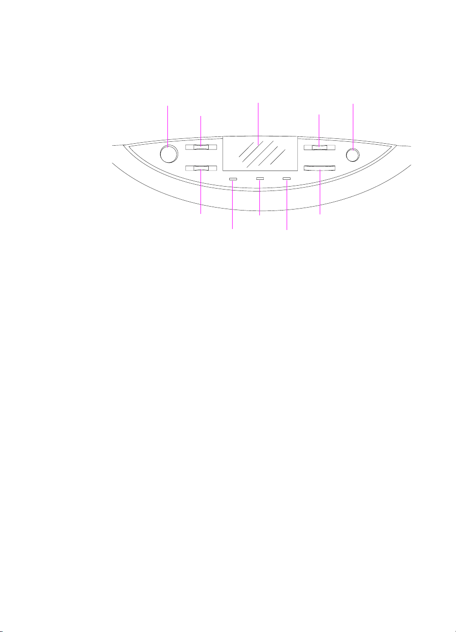
Printer control panel layout
Go
Menu
Item
Figure 13. Location of printer control panel features
Go Brings the printer online or offline and exits menus; will override load
tray messages to print on the de fault media size and type.
Menu Allows access to the printer control panel menus to set the printer
defaults. This key permits both forward and backward movement
through the list of available menus.
LCD display
Data
Ready
– Value +
Attention
Cancel Job
Select
LCD display Presents data about the printer (such as printer status, required
actions, or data and print errors) in one or two lines of characters.
– Value + Steps through the value cho ices f or a particular menu item using – or
+. This key permits both forward and backward movement through
the values.
Cancel Job Stops the curr ent job from p rinting. If no job is printing a nd the displa y
indicates that a job is processing, C
currently processing and the next job begins to print. While the job is
being canceled, CANCELING JOB is displayed.
80 Chapter 3 - Operational overview EN
ANCEL JOB cancels the job
Page 83

Item Steps through the items in a particular menu. This key permits both
forward and backward movement through the available items. Use
the right side of the key to activate online help in all HP Color
LaserJet 8550 printer models.
Ready
Indicator
(green)
l On—The printer is online and able to accept and process data.
l Off—The printer is offline and unable to accept or process data.
l Flashing—The printer is going from online to offline, or from
offline to online.
Data Indicator
(green)
Attention
Indicator
(amber)
l On—Data is in the printer buffer, or the printer is processing data.
l Off—The printer buffer is empty.
l Flashing—The printer is receiving or processing data.
l On—An error has occurred in th e printer.
l Off—The printer does not require attention.
l Flashing—The printer requires attention.
Select Selects the item or value currently shown on the printer cont rol panel
display. An asterisk (*) is displayed when an item has been selected.
EN Printer control panel layout 81
Page 84

Menu maps
Press MENU to cycle through the printer control panel menus. Each
menu is described in a separate table in this section. Menu items are
displayed only if their associated option or function is installed or
activated.
All menus and their associated items are accessible when the printer
is online. In a menu mode, if no keys are pressed for approximately
30 seconds, the system automatically returns to the top level and
displays one of the following:
l READY if the printer was online
l OFFLINE if the printer was offline
l an existing error or service message
Making selections in the printer control panel menus
1 Press MENU until the menu you want appears on the printer
control panel display.
2 Press I
3 Press – V
4 Press S
TEM until the item you want appears on the display.
ALUE + until the value you want appears on the display.
ELECT to save the selection. An asterisk (*) appears to the
right of the selection.
5 Repe a t step s 1 th ro ugh 4 until all of your changes are complete.
6 Press G
O to bring the printer online.
Note Changes in the printer control panel will not take effect until all current
data in the print buffer prints or until the next print job.
82 Chapter 3 - Operational overview EN
Page 85

Information Menu
Press SELECT to print.
The printer displays READY when finished.
Table 15. Information Menu
Item Value Description/action
PRINT MENU MAP None Shows current settings of all menu items.
PRINT CONFIG PAGE None Shows the configuration of the printer
including installed options and serial
numbers.
PRINT PCL FONT
LIST
PRINT PS FONT
LIST
PRINT LASERJET
DEMONSTRATION
PRINT FILE DIRECTORY None Appears only if the printer has a hard disk
PRINT EIO PAGE None Appears only if an EIO device is installed
PRINT CONTINUOUS CONFIG
PAGES
PRINT EVENT LOG None Shows printer events.
None Shows installed PCL fonts including soft
fonts.
None Shows installed PostScript fonts.
None Prints a demonstration page for sales
purposes.
installed.
that supports EIO page printing.
None Used for testing printer operation.
EN Menu maps 83
Page 86

Proof and Print Menu (HP Color LaserJet
8500)
This menu appears only if the printer has a hard disk installed.
Table 16. Proof and Print Menu
Item Value Description/action
<job name>
<job owner>
<job name>
<job owner>
<job name>
<job owner>
<job name>
<job owner>
<job name>
<job owner>
<nn> SELECTED
<nn> PRINTED
<nn> SELECTED
<nn> PRINTED
<nn> SELECTED
<nn> PRINTED
<nn> SELECTED
<nn> PRINTED
<nn> SELECTED
<nn> PRINTED
<nn> = Number of copies
To cancel a proof and print job:
1 Press I
2 Press – V
3 Press S
TEM to display the job name and
job owner.
ALUE + to change the number
of copies to be printed.
ELECT to print the remaining
copies.
- Or Press C
ANCEL JOB or set the number of
copies to zero to delete the remaining
copies.
Quick Copy Jobs Menu (HP Color LaserJet
8550)
This menu appears only if the printer has a hard disk installed.
Table 17. Quick Copy Jobs Menu
Item Value Description/action
<job name>
<job owner>
<job name>
<job owner>
<job name>
<job owner>
<job name>
<job owner>
<job name>
<job owner>
<nn> SELECTED
<nn> PRINTED
<nn> SELECTED
<nn> PRINTED
<nn> SELECTED
<nn> PRINTED
<nn> SELECTED
<nn> PRINTED
<nn> SELECTED
<nn> PRINTED
<nn> = Number of copies
To cancel quick copy jobs:
1 Press I
2 Press – V
3 Press S
TEM to display the job name and
job owner.
of copies to be printed.
copies.
- Or Press C
copies to zero to delete the remaining
copies.
ALUE + to change the number
ELECT to print the remaining
ANCEL JOB or set the number of
84 Chapter 3 - Operational overview EN
Page 87
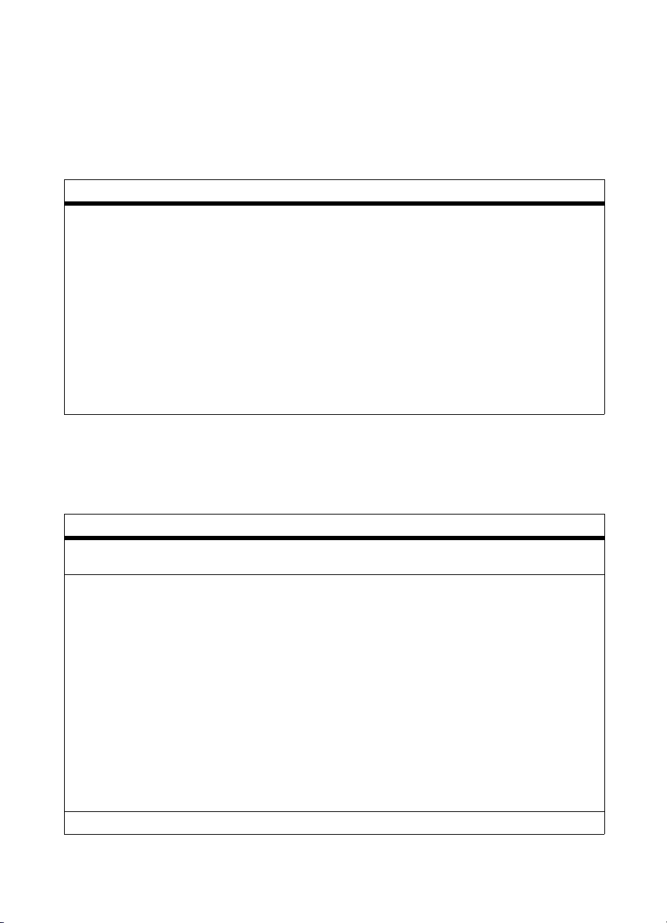
Private/Stored Jobs Menu (HP Color LaserJet
8550)
This menu appears only if the printer has a hard disk installed.
Table 18. Proof and Print Menu
Item Value Description/action
<job name>
<job owner>
<job name>
<job owner>
<job name>
<job owner>
<job name>
<job owner>
<job name>
<job owner>
<nn> SELECTED
<nn> PRINTED
<nn> SELECTED
<nn> PRINTED
<nn> SELECTED
<nn> PRINTED
<nn> SELECTED
<nn> PRINTED
<nn> SELECTED
<nn> PRINTED
<nn> = Number of copies
To cancel private and stored jobs:
1 Press I
2 Press – V
3 Press S
TEM to display the job name and
job owner.
ALUE + to change the number
of copies to be printed.
ELECT to print the remaining
copies.
- Or Press C
ANCEL JOB or set the number of
copies to zero to delete the remaining
copies.
Paper Handling Menu
Table 19. Paper Handling Menu
Item Value Description/action
TRAY 1 MODE=
(HP Color LaserJet 8500 only)
TRAY 1 TYPE= AUTO (8550 only)
* Default setting.
EN Menu maps 85
FIRST*
CASSETTE
Appears only if TRAY 1 MODE=CASSETTE.
PLAIN*
PREPRINTD
LTRHEAD
TRNSPRNCY
PREPUNCHED
LABELS
BOND
RECYCLED
COLOR
CARDSTOCK
HEAVY
GLOSSY
28# TYPE 1
28# TYPE 2
ENVELOPE
Page 88
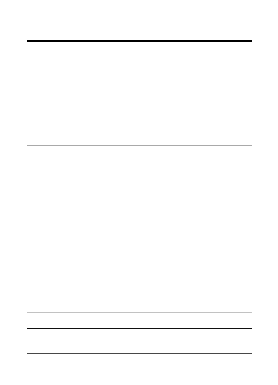
Table 19. Paper Handling Menu (continued)
Item Value Description/action
TRAY 1 SIZE= AUTO (8550 only)
LETTER*
LEGAL
A4
A5
11X17
A3
EXEC
JIS B4
JIS B5
JPOSTD
COM10
MONARCH
C5
DL
B5
CUSTOM
TRAY 2 TYPE=
TRAY 3 TYPE=
TRAY 4 TYPE=
PAPER DEST= TOP OUTPUT BIN*
DUPLEX= OFF*
BINDING= LONG EDGE*
* Default setting.
PLAIN*
PREPRINTD (plain and
preprinted are
combined to one menu
item on the 8550)
LTRHEAD
TRNSPRNCY (trays 2
and 3 only)
PREPUNCHED
BOND
RECYCLED
COLOR
GLOSSY
28# TYPE 1
28# TYPE 2
LEFT OUTPUT BIN
STACKER OUTBIN
SEPARATOR BIN
MAILBOX 1
MAILBOX 2
MAILBOX 3
MAILBOX 4
MAILBOX 5
MAILBOX 6
MAILBOX 7
MAILBOX 8
ON
SHORT EDGE
Appears only if TRAY 1 MODE=CASSETTE.
The TRAY 4 TYPE= option appears only if
the 2,000-sheet input unit is properly
installed.
The STACKER OUTBIN, SEPARATOR BIN,
and MAILBOX options appear only if the
multi-bin mailbox is installed and configured
for the appropriate mode.
Appears only if a duplexer is properly
installed.
Appears only if DUPLEX= is set to ON.
86 Chapter 3 - Operational overview EN
Page 89

Table 19. Paper Handling Menu (continued)
Item Value Description/action
MANUAL FEED= OFF*
ON
OVERRIDE A4 WITH LETTER= NO*
YES
AUTO PAPER OVERRIDE= OFF*
ON
* Default setting.
Allows the user to feed media into the printer
by hand rather than automatically from an
input tray. The user can select manual feed
instead of automatic input tray as the default
for the paper source. If MANUAL FEED = ON
and an input tray is not selected, then
manual feed is selected.
Enabling this option prints A4-sized
documents on letter-sized media (if letter is
the default size), or it prints letter-sized
documents on A4-sized media (if A4 is the
default size). However, if an input tray is
configured for the size you want to override,
then the printer prints on the correct size of
media regardless of the override setting.
Selects the media the job prints on if the
requested media is not found.
If ON is selected, the printer displays TRAY
<x> LOAD <type> <size>. After a delay the
printer automatically prints on the default
media. The delay time can be changed
through HP JetAdmin software.
If OFF is selected, the printer displays TRAY
<x> LOAD <type> <size> until it detects the
requested media type and size or G
pressed.
O is
EN Menu maps 87
Page 90

Configuration Menu
Table 20. Configuration Menu
Item Value Description/action
POWERSAVE= 30 MIN
1 HOUR*
2 HOURS (8500 only)
3 HOURS
8 HOURS (8550 and
some 8500 models)
10 SEC
PERSONALITY= AUTO*
PCL
PS
CLEARABLE WARNINGS= ON*
JOB
TONER LOW= CONTINUE*
STOP
Sets the length of time after use before the
printer switches to powersave mode.
Note that the 10-second setting is for service
personnel use.
Allows the user to determine which
personality will be the default for the printer.
When AUTO is selected, the printer will
determine which personality to use for each
print job.
Note: PCL support is not available at initial
product introduction.
Determines the amount of time that a
clearable warning is displayed on the printer
control panel. If set to ON, then clearable
warnings are displayed until G
set to JOB, then clearable warnings are
displayed until the end of the print job.
Determines the printer response to
consumable low and out messages
(including TONER LOW, TRANSFER KIT
OUT, FUSER LIFE OUT, and DRUM LIFE
LOW).
O is pressed. If
If set to CONTINUE, clear the message by
pressing G
message by replacing the consumable.
NEW TONER CARTRIDGE=
(8550 only)
QUICK COPY JOBS =
(8550 only)
PRINT PS ERRORS= OFF*
INITIALIZE DISK None Appears only if the appropriate printer hard
* Default setting.
NO
YES
0 to 50 The default is 32.
ON
If the PostScript interpreter detects illegal
commands, the job is canceled. If ON, an
error page prints. If OFF, there is no
indication that an error occurred.
disk is installed.
Press S
O. If set to STOP, clear the
ELECT to initialize.
88 Chapter 3 - Operational overview EN
Page 91
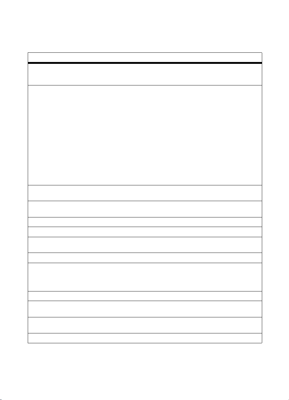
Printing Menu
Table 21. Printing Menu
Item Value Description/action
COPIES= 1* to 999 Sets the number of uncollated copies to be
sent if the number of copies is not defined by
the print job.
PAPER= LETTER*
LEGAL
A4
EXEC
A5
11X17
A3
JIS B4
JIS B5
JPOSTD
ENVELOPE= COM10
MONARCH
C5
DL
B5
CONFIGURE CUSTOM PAPER
(8550 only)
UNIT OF MEASURE (8550 only) INCHES
X DIMENSION (8550 only) 3.87 . . . 11.7*
Y DIMENSION (8550 only) 7.5 . . . 17.7*
ORIENTATION= PORTRAIT*
FORM LENGTH= 5 . . . 60* . . . 128 LINES
PCL FONT SOURCE= SOFT
PCL FONT NUMBER= 0 (Courier)* to 999
PCL PITCH= 0.44 . . . 10* . . . 99.99 Appears only if the selected font is a fixed-
PCL POINT SIZE= 4.00 . . . 12* . . . 999.75 Appears only if the selected font is a
*Default setting.
NO
YES
MILLIMETERS
LANDSCAPE
INTERNAL*
SLOT n (n = 1, 2, 3, 4)
Sets the default media size. The default
media size is used for jobs that do not
include media size commands, or when the
requested media size is not installed in the
printer.
ENVELOPE is not a separate item. The
printer control panel display switches when
- V
ALUE + gets to envelope sizes.
Sets the default font source to search first f or
the requested fonts. Soft fonts are selected
first, DIMM fonts second, and internal fonts
third, if all are installed.
spaced contour font.
proportional-spaced contour font.
EN Menu maps 89
Page 92
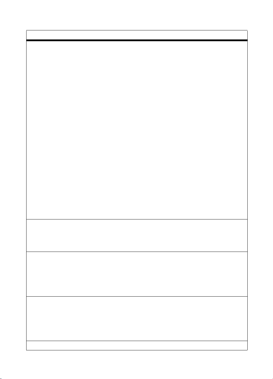
Table 21. Printing Menu (continued)
Item Value Description/action
PCL SYMBOL SET= PC-8*
ROMAN-8
ISO L1
ISO L2
ISO L5
ISO L6
PC-775
PC-8 DN
PC-850
PC-852
PC-8TK
PC-1004
WIN L1
WIN L2
WIN L5
WINBAL T
DESKTOP
PS TEXT
LEGAL
ISO-4
ISO-6
ISO-11
ISO-15
ISO-16
ISO-17
ISO-21
ISO-60
ISO-69
WIN 3.0
MC TEXT
COURIER= REGULAR*
DARK
WIDE A4= NO*
YES
APPEND CR TO LF= NO*
YES
*Default setting.
Default symbol-set mapping. Used only for
jobs that do not include symbol-set selection
commands.
DARK emulates the heavier Courier font of
the HP LaserJet III printer. REGULAR is the
lighter and more accurate Courier font used
since the HP LaserJet 4 printer and in books
and magazines.
Allows the user to change the printable area
of A4-sized media so that eighty 10-pitch
characters can be printed on one line. The
printer will print past the normal 5-mm
boundaries on the sides of the page. This
setting is useful if printing files formatted for
letter-sized media on A4-sized media.
These are control characters identified in
ASCII to control the cursor (which is the
current printing position). LF (line feed)
moves the cursor down one row without
changing the column position. CR (carriage
return) moves the cursor back to column 1
without moving it down a row.
90 Chapter 3 - Operational overview EN
Page 93

Duplex Registration Menu (HP Color LaserJet
8550)
Table 22. I/O Menu
Item Value Description/action
TRAY 1 PRINT TEST PAGE
TRAY 1 X= -5 . . . 0* . . . 5
TRAY 1 Y= -5 . . . 0* . . . 5
TRAY 2 PRINT TEST PAGE
TRAY 2 X= -5 . . . 0* . . . 5
TRAY 2 Y= -5 . . . 0* . . . 5
TRAY 3 PRINT TEST PAGE
TRAY 3 X= -5 . . . 0* . . . 5
TRAY 3 Y= -5 . . . 0* . . . 5
TRAY 4 PRINT TEST PAGE
TRAY 4 X= -5 . . . 0* . . . 5
TRAY 4 Y= -5 . . . 0* . . . 5
* Default setting.
I/O Menu
If an EIO card is installed, an additional EIO menu will appear.
Table 23. I/O Menu
Item Value Description/action
I/O TIMEOUT= 5 . . . 151 . . . 302 . . . 300 Period of time, in seconds, that the printer
PARALLEL ADV
FUNCTIONS=
1
Default setting for HP Color LaserJet 8550.
2
Default setting for HP Color LaserJet 8500.
EN Menu maps 91
ON*
OFF
will wait without seeing data before
considering the job complete and printing it.
Does not have an effect for jobs with end-ofjob markers.
Forces parallel port to compatibility mode,
which can be more reliable in some cases,
but will not allow the printer status to be sent
to the host computer.
Page 94

Resets Menu
Table 24. Resets Menu
Item Value Description/action
FACTORY DEFAULT RESET None Resets menus to the factory settings. I/O
Menu and Color Adjust Menu values do not
change.
RESET ACTIVE I/O None Resets I/O to known state.
RESET ALL I/O None Used to clear I/O problems.
RESET TRANSFER LIFE
COUNT
RESET FUSER LIFE COUNT None Used to indicate that a new fuser kit has
None Used to indicate that a new transfer kit has
been installed.
been installed.
Color Adjust Menu
Table 25. Color Adjust Menu
Item Value Description/action
PRINT TEST PAGE None
BLACK SMOOTH VALUE= -6 ... 0 ... +6
CYAN SMOOTH VALUE= -6 ... 0 ... +6
MAGENTA SMOOTH VALUE= -6 ... 0 ... +6
YELLOW SMOOTH VALUE= -6 ... 0 ... +6
BLACK DETAIL VALUE= -6 ... 0 ... +6
CYAN DETAIL VALUE= -6 ... 0 ... +6
MAGENTA DETAIL VALUE= -6 ... 0 ... +6
YELLOW DETAIL VALUE= -6 ... 0 ... +6
See page 457 for information
about using this menu.
92 Chapter 3 - Operational overview EN
Page 95

Service Mode Menu
The Service Mode Menu can be entered only by pressing the left side
of the I
TEM and the VALUE keys at the same time. For more
information about using the Service Mode Menu, see page 420.
l NVRAM SETTING (nonvolatile random-access memory setting)
menu is provided to replace values that might be lost when a
formatter board or control board is repl aced in the field.
l FORMATTER DIAGNOSTICS menu is provided for
manufacturing and field service personnel to perform specific
diagnostic tests on the formatter board and its related
components.
• Service personnel can pinpoint problem areas on the f ormatter
board for replaceme nt or for tracking defects.
• The operator can choose which tests are enab led and disabled
during execution, whether the tests run once or continuously,
and whether the test sequence stops upon f ailure or contin ues
despite failure.
• A fault log is implemented within formatter diagnostics to
record errors for review.
• Because many of the formatter diagnostic tests are destructiv e
memory tests, a special key sequence is used to enter the
mode. A message warns service personnel that the printer is
about to perform destructive memory tests.
Table 26. Service Mode Menu
Service Mode Menu Item Value Description/action
NVRAM SETTING SERIAL NUMBER <xxxxxxxxxx> This number is the serial
FORMATTER NUMBER <xxxxxxxxxx> This number is the serial
TOTAL PAGE COUNT <xxxxxxxxxx> Total number of pages
COLOR PAGE COUNT <xxxxxxxxxx> Number of color pages
* Default setting.
EN Menu maps 93
number of the printer.
Press – V
value of the current character.
Press S
and move to the next character.
number of the formatter board.
Enter the number in the same
manner as the serial number of
the printer.
processed.
processed.
ALUE + to change the
ELECT to save the value
Page 96

Table 26. Service Mode Menu (continued)
Service Mode Menu Item Value Description/action
NVRAM SETTING
(continued)
FORMATTER
DIAGNOSTICS
* Default setting.
DUPLEX COUNT <xxxxxxxxxxxx> Number of duplex pages
processed.
TRANSFER LIFE LEFT <xxxx> Remaining life, from 0 to 100
percent.
FUSER LIFE LEFT <xxxx> Remaining life, from 0 to 100
percent.
ENGINE SETTING 1 <xxxxxxxxxxxx> The registration values of the
engine used to align the various
color planes. The values are
listed on a sticker inside the
front of the printer (to the left of
the printer control panel and to
the right of the front door). Enter
these values only when
replacing the control board.
Enter only 12 characters for
each engine setting (0 [zero] to
F). The last two digits of the
engine setting might change
after setting because of varying
checksum values. This
difference is acceptable.
ENGINE SETTING 2 <xxxxxxxxxxxx> See ENGINE SETTING 1.
CR PAPER SIZE LETTER*
A4
The cold reset (CR) paper size
is the default media size in the
country for which the printer is
localized. If the NVRAM
SETTING menu is used to
change the CR PAPER SIZE,
the PAPER= setting in the
Printing Menu also changes to
make the new CR PAPER SIZE
the default media size.
CLEAR EVENT LOG NO*
Clears the printer event log.
YES
EXECUTE TESTS Press S
ELECT to enter the
FORMATTER DIAGNOSTICS
menu. I
TEM and – VALUE + do
not function until S
ELECT is
pressed. Once the
FORMATTER DIAGNOSTICS
menu has been entered, M
moves only between the
FORMATTER DIAGNOSTICS
and FAULT LOG.
ENU
94 Chapter 3 - Operational overview EN
Page 97

Table 26. Service Mode Menu (continued)
Service Mode Menu Item Value Description/action
REPEAT= NO*
YES
ON FAULT= BREAK*
CONT
PAUSE
ROM CRC= YES*
NO
DRAM DIMM= YES*
NO
IDE ASIC= YES*
NO
DISK= YES*
NO
VX ASIC= YES*
NO
FAULT LOG first fault message
. . .
last fault msg
POWER OFF TO EXIT Turn the printer off and on to
PAPER PATH EXECUTE TEST Press S
* Default setting.
BREAK stops at error and only
the printer control panel
displays a message.
CONTINUE does not stop at
error, and error is posted only to
the fault log.
PAUSE stops at error and the
printer control panel displays a
message. Press S
ELECT to
continue. Then, error is also
posted to the fault log.
Firmware read-only memory
(ROM) is tested.
Installed DIMMs are tested to
verify that they are supported
by the formatter board and
functioning properly.
This test verifies the read and
write integrity of the formatter
IDE ASIC.
Used to verify the integrity of
the printer hard disk and the
interface between the printer
hard disk and the printer. This
test also ensures that the
printer hard disk buffering and
caching are working properly.
This test verifies the read and
write integrity of the formatter
VX ASIC.
Records all errors that occurred
while formatter diagnostics
tests were executing. FAULT
LOG does not appear until the
formatter diagnostics have been
run and a failure exists. The
fault log is cleared when the
printer is turned off.
exit the formatter diagnostics
and reset the printer.
ELECT to execute tests.
EN Menu maps 95
Page 98
Table 26. Service Mode Menu (continued)
Service Mode Menu Item Value Description/action
REPETITIONS 1* . . . 10
TRAY 1= ON*
OFF
TRAY 2= ON*
OFF
TRAY 3= ON*
OUTPUT = TOP OUTPUT BIN*
DEVELOPER MOTOR REPETITIONS 1* . . . 10
EXECUTE TEST
DRUM MOTOR REPETITIONS 1* . . . 10
EXECUTE TEST
SENSOR MONITOR EXECUTE TEST 0123456789AB
OFF
LEFT OUTPUT BIN
000000000000
Once EXECUTE TEST is
selected, the current value (0 or
1) of each of the 10 sensors is
shown on the display, on the
lower line. The upper line of the
display shows digits to be used
as identifiers.
For information about
performing this test and an
explanation of the digits in the
upper line of the display, see
page 423.
EXIT SERVICE MODE
* Default setting.
96 Chapter 3 - Operational overview EN
Page 99

Selecting the display language
The printer supports printer messages and prints configuration pages
in a variety of languages. Use the printer control panel to set the
display language.
1 To enter configure language mode, hold down S
ELECT while
turning the printer on. When CONFIG LANGUAGE (in English)
appears on the printer control panel displa y f or appro ximately one
second, release S
ELECT. Once the printer has restarted,
LANGUAGE = ENGLISH appears on the display.
Note Only – VALUE +, SELECT, and GO are activ e while the displa y language
is being configured. All other keys are ignored.
If you press G
O without selecting a language, the printer brings itself
online and all subsequent messages are in English. However , because
no display language was selected, the LANGUAGE = ENGLISH
message reappears (after the power-on self test) when the printer is
turned on again. This message appears e very time the printer is turned
on until you select a language through the configure language mode.
2 Press – V
ALUE + until the language you want appears on the
display.
3 Press S
ELECT to save the selection. An asterisk (*) appears to the
right of the selection. The languag e se lected is the default
language until another selection is made by restarting the printer
in the configure language mode.
4 Press G
O.
5 Tu rn the printer off and back on.
Note See the HP Color LaserJet 8550 MFP printer Service Manual for
information about how to change the display language on the copy
module.
EN Selecting the display language 97
Page 100
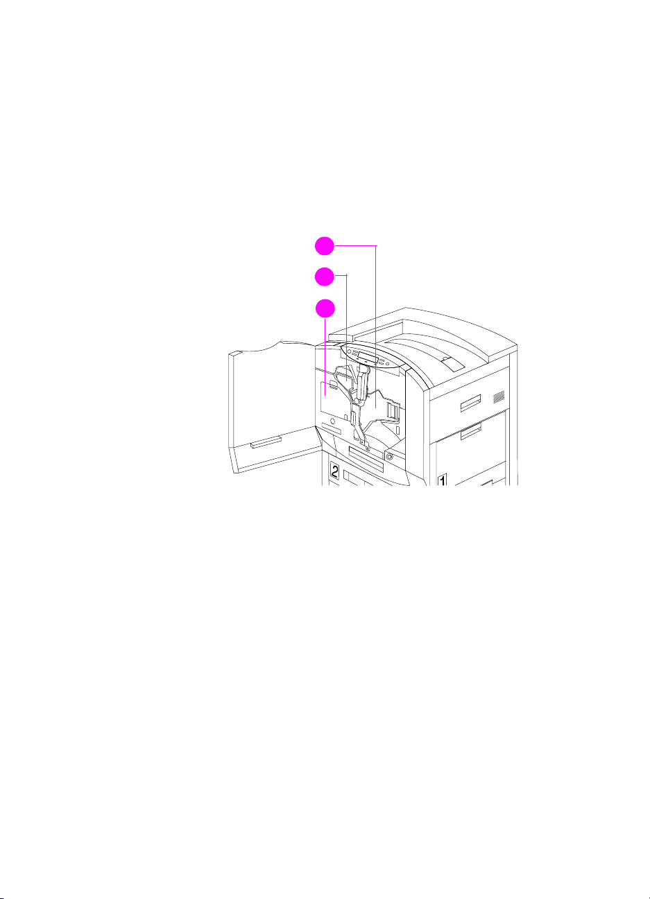
Installing the consumables
When installing a new printer, install the consumables in the printer in
this order:
1 Ima gin g drum
2 Black toner cartridge
3 Color toner cartridges
1
2
3
Figure 14. Consumables installation
98 Chapter 3 - Operational overview EN
 Loading...