

Page 1

8550 Printer
Copy Module
Automatic Document Feeder
High-Capacity Input
Service Manual
English
Page 2

Page 3

HP Copy Module, ADF, and side
HCI for HP Color LaserJet 8550
series printers
_____________ Service Manual
Page 4

Copyright Information
Copyright © 2000 HewlettPackard Company
All Rights Reserved.
Reproduction, adaptations, or
translation without prior written
permission is prohibited except
as allowed under copyright
laws.
Part number C7834-90902
First edition, April 2000
Printed in USA
Warranty
The information contained in
this document is subject to
change without notice.
Hewlett-Packard makes no
warranty of any kind with
respect to this information.
HEWLETT-PACKARD
SPECIFICALLY DISCLAIMS
THE IMPLIED WARRAN TY OF
MERCHANTABILITY AND
FITNESS FOR A PARTICULAR
PURPOSE.
Hewlett-Packard shall not be
liable for any direct, indirect,
incidental, consequential, or
other damage alleged in
connection with the furnishing or
use of this information.
NOTICE TO U.S.
GOVERNMENT USERS:
RESTRICTED RIGHTS
COMMERCIAL COMPUTER
SOFTWARE: “Use, duplication,
or disclosure by the
Government is subject to
restrictions as set forth in
subparagraph (c) (1)(ii) of the
Rights in Technical Data Clause
at DFARS 52.227-7013.
Trademark Credits
CompuServe™ is a U.S.
trademark of CompuServe, Inc.
MS-DOS
®
is a U.S. registered
trademark of Microsoft
Corporation.
Photoshop™ and PostScript
®
are registered trademarks of
Adobe Systems Incorporated.
TrueType™ is a U.S. trademark
of Apple Computer, Inc.
®
UNIX
is a registered trademark
in the United States and other
countries, licensed exclusively
through X/Open Company
Limited.
Safety Information
WARNING
Electrical Shock Hazard
To avoid electrical shock, use
only supplied power cords and
connect only to properly
grounded (3-hole) wall outlets.
Hewlett-Packard Company
11311 Chinden Boulevard
Boise, Idaho 83714 U.S.A.
Page 5

Contents
1 Product information
Chapter contents. . . . . . . . . . . . . . . . . . . . . . . . . . . . . . . . . . . . . .21
Introduction . . . . . . . . . . . . . . . . . . . . . . . . . . . . . . . . . . . . . . . . . .23
Copy module . . . . . . . . . . . . . . . . . . . . . . . . . . . . . . . . . . . . . . . . .23
Automatic document feeder (ADF) . . . . . . . . . . . . . . . . . . . . . . . .28
Side high-capacity input (side HCI) . . . . . . . . . . . . . . . . . . . . . . .32
Model and serial numbers. . . . . . . . . . . . . . . . . . . . . . . . . . . . . . .35
Safety and regulatory information . . . . . . . . . . . . . . . . . . . . . . . .35
2 Service approach
Chapter contents. . . . . . . . . . . . . . . . . . . . . . . . . . . . . . . . . . . . . .37
Service approach overview . . . . . . . . . . . . . . . . . . . . . . . . . . . . . .39
Parts and supplies . . . . . . . . . . . . . . . . . . . . . . . . . . . . . . . . . . .39
Ordering . . . . . . . . . . . . . . . . . . . . . . . . . . . . . . . . . . . . . . . . . . . .40
Technical assistance. . . . . . . . . . . . . . . . . . . . . . . . . . . . . . . . . . .42
Warranty . . . . . . . . . . . . . . . . . . . . . . . . . . . . . . . . . . . . . . . . . . .46
3 Operational overview
Chapter contents. . . . . . . . . . . . . . . . . . . . . . . . . . . . . . . . . . . . . .47
Control panel. . . . . . . . . . . . . . . . . . . . . . . . . . . . . . . . . . . . . . . . .49
Copy module functionality . . . . . . . . . . . . . . . . . . . . . . . . . . . . . . .51
Self-diagnostic messages . . . . . . . . . . . . . . . . . . . . . . . . . . . . . . .59
Service mode . . . . . . . . . . . . . . . . . . . . . . . . . . . . . . . . . . . . . . . .60
4 Adjustments and maintenance
Chapter contents. . . . . . . . . . . . . . . . . . . . . . . . . . . . . . . . . . . . .117
Overview . . . . . . . . . . . . . . . . . . . . . . . . . . . . . . . . . . . . . . . . . . .119
MFP print engine adjustments. . . . . . . . . . . . . . . . . . . . . . . . . . .119
Copy module adjustments. . . . . . . . . . . . . . . . . . . . . . . . . . . . . .121
ADF adjustments. . . . . . . . . . . . . . . . . . . . . . . . . . . . . . . . . . . . .140
Side HCI adjustments . . . . . . . . . . . . . . . . . . . . . . . . . . . . . . . . .159
Periodically replaced parts . . . . . . . . . . . . . . . . . . . . . . . . . . . . .163
Cleaning . . . . . . . . . . . . . . . . . . . . . . . . . . . . . . . . . . . . . . . . . . .164
Lubricating. . . . . . . . . . . . . . . . . . . . . . . . . . . . . . . . . . . . . . . . . .174
EN Contents 3
Page 6

5 Theory of operation
Chapter contents. . . . . . . . . . . . . . . . . . . . . . . . . . . . . . . . . . . . .175
Introduction . . . . . . . . . . . . . . . . . . . . . . . . . . . . . . . . . . . . . . . . .177
Notes on the power switch . . . . . . . . . . . . . . . . . . . . . . . . . . . . .177
Copy module . . . . . . . . . . . . . . . . . . . . . . . . . . . . . . . . . . . . . . . .178
ADF. . . . . . . . . . . . . . . . . . . . . . . . . . . . . . . . . . . . . . . . . . . . . . .244
Side HCI . . . . . . . . . . . . . . . . . . . . . . . . . . . . . . . . . . . . . . . . . . .304
6 Removal and replacement
Chapter contents. . . . . . . . . . . . . . . . . . . . . . . . . . . . . . . . . . . . .327
Required tools . . . . . . . . . . . . . . . . . . . . . . . . . . . . . . . . . . . . . .331
Repair notices . . . . . . . . . . . . . . . . . . . . . . . . . . . . . . . . . . . . . .332
Copy module . . . . . . . . . . . . . . . . . . . . . . . . . . . . . . . . . . . . . . .333
Automatic document feeder (ADF) . . . . . . . . . . . . . . . . . . . . . . .377
Side HCI . . . . . . . . . . . . . . . . . . . . . . . . . . . . . . . . . . . . . . . . . . .434
7 Troubleshooting
Chapter contents. . . . . . . . . . . . . . . . . . . . . . . . . . . . . . . . . . . . .455
System-to-device troubleshooting. . . . . . . . . . . . . . . . . . . . . . . .457
Copy module troubleshooting . . . . . . . . . . . . . . . . . . . . . . . . . . .460
ADF troubleshooting . . . . . . . . . . . . . . . . . . . . . . . . . . . . . . . . . .528
Side HCI troubleshooting . . . . . . . . . . . . . . . . . . . . . . . . . . . . . .535
8 Parts and diagrams
Chapter contents. . . . . . . . . . . . . . . . . . . . . . . . . . . . . . . . . . . . .547
How to use this chapter. . . . . . . . . . . . . . . . . . . . . . . . . . . . . . . .551
Printer parts unique to the HP Color LaserJet 8550MFP . . . . . .552
Stand. . . . . . . . . . . . . . . . . . . . . . . . . . . . . . . . . . . . . . . . . . . . . .555
Copy module . . . . . . . . . . . . . . . . . . . . . . . . . . . . . . . . . . . . . . . .558
ADF. . . . . . . . . . . . . . . . . . . . . . . . . . . . . . . . . . . . . . . . . . . . . . .600
Side HCI . . . . . . . . . . . . . . . . . . . . . . . . . . . . . . . . . . . . . . . . . . .649
Numerical parts list . . . . . . . . . . . . . . . . . . . . . . . . . . . . . . . . . . .672
Alphabetical parts list . . . . . . . . . . . . . . . . . . . . . . . . . . . . . . . . .680
Index
4 Contents EN
Page 7

Figures
Figure 1. Copy module front left . . . . . . . . . . . . . . . . . . . . . . . 26
Figure 2. Copy module front right . . . . . . . . . . . . . . . . . . . . . .26
Figure 3. Copy module cross-section . . . . . . . . . . . . . . . . . . .27
Figure 4. Automatic document feeder . . . . . . . . . . . . . . . . . . . 30
Figure 5. Automatic document feeder cross-section . . . . . . . 31
Figure 6. Front of side HCI . . . . . . . . . . . . . . . . . . . . . . . . . . . 33
Figure 7. Rear of side HCI . . . . . . . . . . . . . . . . . . . . . . . . . . . 33
Figure 8. Cross-section of side HCI . . . . . . . . . . . . . . . . . . . . 34
Figure 9. Copy module control panel . . . . . . . . . . . . . . . . . . . 49
Figure 10. Service mode initial screen . . . . . . . . . . . . . . . . . . .61
Figure 11. Service label (inside the lower front cover of
the copy module) . . . . . . . . . . . . . . . . . . . . . . . . . . . 62
Figure 12. Example of a Level 1/Level 2 item screen . . . . . . . . 63
Figure 13. Example of a Level 3 screen . . . . . . . . . . . . . . . . . . 64
Figure 14. Copier, display mode Level 1/Level 2 screen . . . . .65
Figure 15. JAM screen . . . . . . . . . . . . . . . . . . . . . . . . . . . . . . .71
Figure 16. ERR screen . . . . . . . . . . . . . . . . . . . . . . . . . . . . . . . 76
Figure 17. Copier, I/O mode Level 1/Level 2 screen . . . . . . . . 77
Figure 18. Copier, I/O mode Level 3 screen example . . . . . . .78
Figure 19. Copier, adjust mode Level 1/Level 2 screen . . . . . . 83
Figure 20. BLANK margins . . . . . . . . . . . . . . . . . . . . . . . . . . . .91
Figure 21. Copier, run/check mode Level 1/Level 2 screen . . .93
Figure 22. Copier, machine settings mode
Level 1/Level 2 screen . . . . . . . . . . . . . . . . . . . . . . . 98
Figure 23. Copier, test print mode Level 1/Level 2 screen . . .108
Figure 24. Counter mode, Level 1/Level 2 screen . . . . . . . . .111
Figure 25. Feeder screen, example of a Level 3 item . . . . . .114
Figure 26. Image and non-image width of the leading edge . .122
Figure 27. Image and non-image width of the left or
right margin . . . . . . . . . . . . . . . . . . . . . . . . . . . . . . 122
Figure 28. BLANK margins . . . . . . . . . . . . . . . . . . . . . . . . . . .123
Figure 29. Adjusting horizontal registration . . . . . . . . . . . . . . 124
Figure 30. Service label . . . . . . . . . . . . . . . . . . . . . . . . . . . . .129
Figure 31. Standard white plate barcode . . . . . . . . . . . . . . . .134
Figure 32. Adjusting the ADF height . . . . . . . . . . . . . . . . . . . .141
Figure 33. DADF controller PCB cover . . . . . . . . . . . . . . . . . . 142
Figure 34. DSW1 on the DADF controller PCB . . . . . . . . . . . 142
Figure 35. SW3 DADF controller PCB . . . . . . . . . . . . . . . . . . 143
EN Figures 5
Page 8

Figure 36. Testing the ADF adjustment . . . . . . . . . . . . . . . . .143
Figure 37. Rear view of the ADF . . . . . . . . . . . . . . . . . . . . . . 144
Figure 38. Adjusting screw . . . . . . . . . . . . . . . . . . . . . . . . . . . 144
Figure 39. DSW1 on the DADF controller PCB . . . . . . . . . . . 145
Figure 40. Testing adjustment . . . . . . . . . . . . . . . . . . . . . . . .146
Figure 41. Adjusting ADF document tray . . . . . . . . . . . . . . . .146
Figure 42. DSW1 on DADF controller PCB . . . . . . . . . . . . . . 147
Figure 43. Measuring the copy paper stop position . . . . . . . . 148
Figure 44. DSW1 on DADF controller PCB . . . . . . . . . . . . . . 149
Figure 45. Positioning paper . . . . . . . . . . . . . . . . . . . . . . . . . .150
Figure 46. Retaining plate adjustment . . . . . . . . . . . . . . . . . .151
Figure 47. Measu rin g th e dis tance from
the copyboard glass to the ADF . . . . . . . . . . . . . .151
Figure 48. Preparing test strips for measuring feeding power. 152
Figure 49. DADF controller cover . . . . . . . . . . . . . . . . . . . . . . 152
Figure 50. DSW1 on DADF controller PCB . . . . . . . . . . . . . . 153
Figure 51. Measuring feeding power . . . . . . . . . . . . . . . . . . . 153
Figure 52. Lock nut glued in place . . . . . . . . . . . . . . . . . . . . .154
Figure 53. ADF sensors . . . . . . . . . . . . . . . . . . . . . . . . . . . . .155
Figure 54. LED 1 and 2 on DADF controller PCB . . . . . . . . . . 156
Figure 55. DADF controller PCB . . . . . . . . . . . . . . . . . . . . . . .157
Figure 56. Wing nuts on the adjustment screws . . . . . . . . . . .159
Figure 57. Base plate securing screws . . . . . . . . . . . . . . . . . .160
Figure 58. Paper guide fixing screws . . . . . . . . . . . . . . . . . . .161
Figure 59. Paper guides . . . . . . . . . . . . . . . . . . . . . . . . . . . . . 161
Figure 60. Paper size card . . . . . . . . . . . . . . . . . . . . . . . . . . .162
Figure 61. Copyboard glass . . . . . . . . . . . . . . . . . . . . . . . . . .165
Figure 62. Copyboard cover . . . . . . . . . . . . . . . . . . . . . . . . . . 165
Figure 63. Belt assembly . . . . . . . . . . . . . . . . . . . . . . . . . . . . 168
Figure 64. Document tray . . . . . . . . . . . . . . . . . . . . . . . . . . . .168
Figure 65. Sensors . . . . . . . . . . . . . . . . . . . . . . . . . . . . . . . . . 169
Figure 66. Sensor S1 . . . . . . . . . . . . . . . . . . . . . . . . . . . . . . .169
Figure 67. Reflecting face sensor . . . . . . . . . . . . . . . . . . . . . .170
Figure 68. Registration sensor . . . . . . . . . . . . . . . . . . . . . . . .170
Figure 69. Guide plate . . . . . . . . . . . . . . . . . . . . . . . . . . . . . .171
Figure 70. Registration sensor . . . . . . . . . . . . . . . . . . . . . . . .171
Figure 71. Registration sensor LED3 cover . . . . . . . . . . . . . .172
Figure 72. Light-emitting face . . . . . . . . . . . . . . . . . . . . . . . . . 172
Figure 73. Separation guide . . . . . . . . . . . . . . . . . . . . . . . . . . 173
Figure 74. Control panel power soft switch, copy module
rear power switch, and power plug . . . . . . . . . . . .177
Figure 75. Copy module . . . . . . . . . . . . . . . . . . . . . . . . . . . . . 178
Figure 76. Electrical circuitry . . . . . . . . . . . . . . . . . . . . . . . . . .179
6 Figures EN
Page 9

Figure 77. Inputs to and outputs from
the reader controller PCB (1 of 3) . . . . . . . . . . . . .180
Figure 78. Inputs and outputs from the
reader controller PCB (2 of 3) . . . . . . . . . . . . . . . . 181
Figure 79. Inputs and outputs from the
reader controller PCB (3 of 3) . . . . . . . . . . . . . . . . 182
Figure 80. Basic sequence of operations at power-on . . . . . . 183
Figure 81. A4- and letter-size, 2 copies, 4-color, Direct, and
cassette 1 sequence of operations (1 of 2) . . . . . .185
Figure 82. A4- and letter-size, 2 copies, 4-color, Direct, and
cassette 1 sequence of operations (2 of 2) . . . . . .186
Figure 83. Cross-section of exposure system . . . . . . . . . . . .188
Figure 84. Exposure system mechanics . . . . . . . . . . . . . . . . .188
Figure 85. A4- and letter-size, 2 copies, 4-color, Direct,
cassette 1 sequence of operations . . . . . . . . . . . .189
Figure 86. Scanner movement . . . . . . . . . . . . . . . . . . . . . . . . 190
Figure 87. Scanner motor circuit . . . . . . . . . . . . . . . . . . . . . . .191
Figure 88. Changing the reproduction ratio . . . . . . . . . . . . . .192
Figure 89. Controlling the scanning lamp . . . . . . . . . . . . . . . .193
Figure 90. Paper selection sensors . . . . . . . . . . . . . . . . . . . . 197
Figure 91. Sensor operation . . . . . . . . . . . . . . . . . . . . . . . . . . 198
Figure 92. Image processing unit . . . . . . . . . . . . . . . . . . . . . 200
Figure 93. CCD lines and filters . . . . . . . . . . . . . . . . . . . . . . . 201
Figure 94. CCD circuit . . . . . . . . . . . . . . . . . . . . . . . . . . . . . . 202
Figure 95. Analog circuit . . . . . . . . . . . . . . . . . . . . . . . . . . . . .203
Figure 96. G image signal . . . . . . . . . . . . . . . . . . . . . . . . . . . .205
Figure 97. Digital image processing . . . . . . . . . . . . . . . . . . . 207
Figure 98. Scanning lamp and lens . . . . . . . . . . . . . . . . . . . . 208
Figure 99. Shading correction measurement . . . . . . . . . . . . .209
Figure 100. CCD position matching . . . . . . . . . . . . . . . . . . . . . 210
Figure 101. Text identification . . . . . . . . . . . . . . . . . . . . . . . . . 211
Figure 102. Sensor color correction measurement . . . . . . . . .212
Figure 103. Background pixel measurement . . . . . . . . . . . . . .213
Figure 104. Input level . . . . . . . . . . . . . . . . . . . . . . . . . . . . . . .215
Figure 105. Weak and strong sharpness . . . . . . . . . . . . . . . . . 215
Figure 106. Original density compared to CCD output . . . . . .216
Figure 107. Density level conversion . . . . . . . . . . . . . . . . . . . . 216
Figure 108. BGR and YMC levels . . . . . . . . . . . . . . . . . . . . . .217
Figure 109. BGR to YMC conversion . . . . . . . . . . . . . . . . . . . . 218
Figure 110. Gray components . . . . . . . . . . . . . . . . . . . . . . . . .219
Figure 111. Bk signal . . . . . . . . . . . . . . . . . . . . . . . . . . . . . . . . 220
Figure 112. UCR amount . . . . . . . . . . . . . . . . . . . . . . . . . . . . .220
Figure 113. Chromatic absorption characteristics . . . . . . . . . . 221
Figure 114. Enlargement/correction . . . . . . . . . . . . . . . . . . . . 223
EN Figures 7
Page 10

Figure 115. Image shifts . . . . . . . . . . . . . . . . . . . . . . . . . . . . .224
Figure 116. Shift in main and sub-scanning directions . . . . . .224
Figure 117. Center Shift . . . . . . . . . . . . . . . . . . . . . . . . . . . . . . 225
Figure 118. Mirror image . . . . . . . . . . . . . . . . . . . . . . . . . . . . .226
Figure 119. Mirror image principle . . . . . . . . . . . . . . . . . . . . . . 226
Figure 120. Image repeat . . . . . . . . . . . . . . . . . . . . . . . . . . . .227
Figure 121. Image repeat principle . . . . . . . . . . . . . . . . . . . . . 227
Figure 122. Slant . . . . . . . . . . . . . . . . . . . . . . . . . . . . . . . . . . .228
Figure 123. Slant principle . . . . . . . . . . . . . . . . . . . . . . . . . . . .228
Figure 124. Curve for items A through D . . . . . . . . . . . . . . . . .229
Figure 125. Curve for black-and-white text mode . . . . . . . . . .229
Figure 126. Framing . . . . . . . . . . . . . . . . . . . . . . . . . . . . . . . . .230
Figure 127. Blanking . . . . . . . . . . . . . . . . . . . . . . . . . . . . . . . . .230
Figure 128. Control panel . . . . . . . . . . . . . . . . . . . . . . . . . . . . .233
Figure 129. Copy module fan . . . . . . . . . . . . . . . . . . . . . . . . .234
Figure 130. Cooling fan engaged . . . . . . . . . . . . . . . . . . . . . .234
Figure 131. Power . . . . . . . . . . . . . . . . . . . . . . . . . . . . . . . . . .236
Figure 132. Copy module power distribution . . . . . . . . . . . . . .237
Figure 133. Copy module general circuit diagram (1 of 2) . . . . 240
Figure 134. Copy module general circuit diagram (2 of 2) . . . . 242
Figure 135. ADF electrical circuitry . . . . . . . . . . . . . . . . . . . . . .244
Figure 136. Operation mode communication . . . . . . . . . . . . . .245
Figure 137. Inputs to the DADF controller PCB (1 of 2) . . . . . . 246
Figure 138. Inputs to the DADF controller PCB (2 of 2) . . . . . . 247
Figure 139. Outputs to the DADF controller PCB . . . . . . . . . . .248
Figure 140. ADF motors . . . . . . . . . . . . . . . . . . . . . . . . . . . . . . 249
Figure 141. Top pick-up path . . . . . . . . . . . . . . . . . . . . . . . . . . 251
Figure 142. Face-up (left) output tray . . . . . . . . . . . . . . . . . . . .253
Figure 143. Face-down (top) output tray . . . . . . . . . . . . . . . . .254
Figure 144. Page composition copy sequences . . . . . . . . . . . .255
Figure 145. Picking up originals . . . . . . . . . . . . . . . . . . . . . . . . 256
Figure 146. Pick-up path . . . . . . . . . . . . . . . . . . . . . . . . . . . . . 257
Figure 147. Feeding sequence . . . . . . . . . . . . . . . . . . . . . . . .258
Figure 148. Feeding . . . . . . . . . . . . . . . . . . . . . . . . . . . . . . . . . 258
Figure 149. Second original pick-up . . . . . . . . . . . . . . . . . . . . .259
Figure 150. Sequence of operations (A4, 2 originals,
top pick-up mode) . . . . . . . . . . . . . . . . . . . . . . . . . 260
Figure 151. Picking up for the first side . . . . . . . . . . . . . . . . . . 261
Figure 152. Reversing from the first side to the second side . . 261
Figure 153. Sequence of operations (reversal) . . . . . . . . . . . . 262
Figure 154. Placement of first original . . . . . . . . . . . . . . . . . . .263
Figure 155. Positioning the first original and pick-up of
second original . . . . . . . . . . . . . . . . . . . . . . . . . . . 263
Figure 156. Movement of first and second originals . . . . . . . . .264
8 Figures EN
Page 11

Figure 157. Delivery of originals . . . . . . . . . . . . . . . . . . . . . . . .264
Figure 158. Sequence of operations (reduced page composition; top
pick-up) . . . . . . . . . . . . . . . . . . . . . . . . . . . . . . . . .265
Figure 159. Delivery path . . . . . . . . . . . . . . . . . . . . . . . . . . . . . 266
Figure 160. Feeding the first original . . . . . . . . . . . . . . . . . . . .266
Figure 161. Delivering the first original and picking up the
second original . . . . . . . . . . . . . . . . . . . . . . . . . . . 267
Figure 162. Sequence of operations (small size, pick-up and
delivery) . . . . . . . . . . . . . . . . . . . . . . . . . . . . . . . . . 268
Figure 163. Detecting an original . . . . . . . . . . . . . . . . . . . . . . . 269
Figure 164. Document tray . . . . . . . . . . . . . . . . . . . . . . . . . . . .270
Figure 165. Registration rollers . . . . . . . . . . . . . . . . . . . . . . . . . 271
Figure 166. Horizontal detection . . . . . . . . . . . . . . . . . . . . . . . . 272
Figure 167. Placement of original . . . . . . . . . . . . . . . . . . . . . . .274
Figure 168. Control of pick-up motor . . . . . . . . . . . . . . . . . . . .275
Figure 169. Control of belt motor . . . . . . . . . . . . . . . . . . . . . . . 277
Figure 170. ADF jam sensors . . . . . . . . . . . . . . . . . . . . . . . . .279
Figure 171. Improper placement of originals . . . . . . . . . . . . . .282
Figure 172. Jam flowchart . . . . . . . . . . . . . . . . . . . . . . . . . . . .284
Figure 173. Power supply . . . . . . . . . . . . . . . . . . . . . . . . . . . . .285
Figure 174. Motors, solenoids, and sensors . . . . . . . . . . . . . . . 286
Figure 175. PCB locations . . . . . . . . . . . . . . . . . . . . . . . . . . . .287
Figure 176. Indicator PCB . . . . . . . . . . . . . . . . . . . . . . . . . . . . 288
Figure 177. ADF general circuit diagram . . . . . . . . . . . . . . . . .290
Figure 178. ADF controller circui t diagram (1 of 7) . . . . . . . . .292
Figure 179. ADF controller circui t diagram (2 of 7) . . . . . . . . . .294
Figure 180. ADF controller circui t diagram (3 of 7) . . . . . . . . . .296
Figure 181. ADF controller circui t diagram (4 of 7) . . . . . . . . . .298
Figure 182. ADF controller circui t diagram (5 of 7) . . . . . . . . . .300
Figure 183. ADF controller circui t diagram (6 of 7) . . . . . . . . . .301
Figure 184. ADF controller circui t diagram (7 of 7) . . . . . . . . . .301
Figure 185. ADF display board . . . . . . . . . . . . . . . . . . . . . . . . .302
Figure 186. ADF general timing chart (top pick-up mode, A4, and 2
originals—single-sided original to single copy) . . . 303
Figure 187. Deck block diagram . . . . . . . . . . . . . . . . . . . . . . . .304
Figure 188. Deck controller PCB . . . . . . . . . . . . . . . . . . . . . . .305
Figure 189. Deck controller PCB output . . . . . . . . . . . . . . . . . . 306
Figure 190. Pick-up feed rollers . . . . . . . . . . . . . . . . . . . . . . . . 307
Figure 191. Pick-up feed signals . . . . . . . . . . . . . . . . . . . . . . . 308
Figure 192. Signal transfer points . . . . . . . . . . . . . . . . . . . . . . 309
Figure 193. Pick-up signal levels . . . . . . . . . . . . . . . . . . . . . . .309
Figure 194. Lifter operation . . . . . . . . . . . . . . . . . . . . . . . . . . . 310
Figure 195. Remaining paper detection . . . . . . . . . . . . . . . . . .311
EN Figures 9
Page 12

Figure 196. Paper-size-detection switch and
detection plate (A4) . . . . . . . . . . . . . . . . . . . . . . . .312
Figure 197. Paper-size-detection switch and
detection plate (LTR) . . . . . . . . . . . . . . . . . . . . . . . 312
Figure 198. Jam detection levels . . . . . . . . . . . . . . . . . . . . . . .313
Figure 199. Stationary jam . . . . . . . . . . . . . . . . . . . . . . . . . . . . 313
Figure 200. Side HCI power supply . . . . . . . . . . . . . . . . . . . . .314
Figure 201. Sensors . . . . . . . . . . . . . . . . . . . . . . . . . . . . . . . .315
Figure 202. Solenoids and motors . . . . . . . . . . . . . . . . . . . . . . 316
Figure 203. PCBs . . . . . . . . . . . . . . . . . . . . . . . . . . . . . . . . . . 317
Figure 204. Deck controller PCB . . . . . . . . . . . . . . . . . . . . . . .319
Figure 205. User LED PCB . . . . . . . . . . . . . . . . . . . . . . . . . . .320
Figure 206. Remaining-paper-detection PCB . . . . . . . . . . . . .320
Figure 207. Deck controller PCB general circuit diagram . . . . . 324
Figure 208. Front view of copy module . . . . . . . . . . . . . . . . . . .333
Figure 209. Rear view of copy module . . . . . . . . . . . . . . . . . . .333
Figure 210. Removing the copy module lower front cover . . . .334
Figure 211. Removing the copy module upp er right cover . . . .334
Figure 212. Removing the copy module upper rear cover . . . . 335
Figure 213. Removing the copy module upper left cover . . . . .335
Figure 214. Removing the copy module rear cover . . . . . . . . .336
Figure 215. Removing the copy module upper front cover . . . .337
Figure 216. Removing the copy module scanner motor . . . . . .338
Figure 217. Removing the copy module th e
scanner motor driver PCB . . . . . . . . . . . . . . . . . . .339
Figure 218. Preparing to remove the ROM DIMM . . . . . . . . . .340
Figure 219. Opening the claws . . . . . . . . . . . . . . . . . . . . . . . . .341
Figure 220. Lifting the ROM DIMM to detach . . . . . . . . . . . . . .341
Figure 221. Inserting the ROM DIMM . . . . . . . . . . . . . . . . . . . . 342
Figure 222. Engaging the ROM DIMM . . . . . . . . . . . . . . . . . . . 342
Figure 223. Control panel . . . . . . . . . . . . . . . . . . . . . . . . . . . . .344
Figure 224. Detaching the control panel . . . . . . . . . . . . . . . . . . 345
Figure 225. Detaching the metal plat e on the LCD assembly .346
Figure 226. Detaching the LCD assembly . . . . . . . . . . . . . . . .346
Figure 227. Copyboard glass . . . . . . . . . . . . . . . . . . . . . . . . . . 347
Figure 228. Scanner drive cable . . . . . . . . . . . . . . . . . . . . . . . . 348
Figure 229. Securing the metal cable clamp (front view) . . . . . 349
Figure 230. Securing the metal cabl e clamp (rear view) . . . . .349
Figure 231. Mirror tool . . . . . . . . . . . . . . . . . . . . . . . . . . . . . . .350
Figure 232. Detaching and reattaching the
mirror positioning tool (front view) . . . . . . . . . . . . .350
Figure 233. Detaching and reattaching the
mirror positioning tool (rear view) . . . . . . . . . . . . .351
10 Figures EN
Page 13

Figure 234. Securing the metal cable clamp to the
mirror 1 mount (front view) . . . . . . . . . . . . . . . . . .351
Figure 235. Securing the metal cable clamp to the
mirror 1 mount (rear view) . . . . . . . . . . . . . . . . . .351
Figure 236. Cable positioning . . . . . . . . . . . . . . . . . . . . . . . . . .352
Figure 237. Copyboard glass . . . . . . . . . . . . . . . . . . . . . . . . . . 353
Figure 238. Flexible cable warning label . . . . . . . . . . . . . . . . . 353
Figure 239. Releasing the connector to the flexible cable . . . . 354
Figure 240. Disconnecting the flexible cable . . . . . . . . . . . . . . 355
Figure 241. Connecting the flexible cable . . . . . . . . . . . . . . . .356
Figure 242. Scanning lamp cover . . . . . . . . . . . . . . . . . . . . . . .357
Figure 243. Scanning lamp inside cover . . . . . . . . . . . . . . . . . .357
Figure 244. Anti-reflecting plate . . . . . . . . . . . . . . . . . . . . . . . 358
Figure 245. Detaching the scanning lamp . . . . . . . . . . . . . . . .359
Figure 246. Removing the scanning lamp . . . . . . . . . . . . . . . .360
Figure 247. Scanning lamp heater . . . . . . . . . . . . . . . . . . . . . .360
Figure 248. Replacing the scanning lamp . . . . . . . . . . . . . . . .361
Figure 249. Scanning lamp adjustment . . . . . . . . . . . . . . . . . .362
Figure 250. White plate cover removal . . . . . . . . . . . . . . . . . . .363
Figure 251. Replacing the white plate cover . . . . . . . . . . . . . . .363
Figure 252. Detaching the claws . . . . . . . . . . . . . . . . . . . . . . . 364
Figure 253. Detaching the intensity-detection PCB . . . . . . . . .364
Figure 254. Lens mount cover . . . . . . . . . . . . . . . . . . . . . . . . . 365
Figure 255. Detaching the CCD unit . . . . . . . . . . . . . . . . . . . . . 365
Figure 256. CCD unit connectors . . . . . . . . . . . . . . . . . . . . . . . 366
Figure 257. Electrical unit screws and connectors . . . . . . . . . . 367
Figure 258. Reader controller PCB connectors . . . . . . . . . . . .367
Figure 259. Removing the reader controller PCB cover (1 of 2) 368
Figure 260. Removing the reader controller PCB cover (2 of 2) 368
Figure 261. Removing the electrical unit . . . . . . . . . . . . . . . . .369
Figure 262. Holding the electrical unit . . . . . . . . . . . . . . . . . . . 369
Figure 263. Detaching the electrical unit cover . . . . . . . . . . . . .370
Figure 264. Electrical unit connectors . . . . . . . . . . . . . . . . . . . . 370
Figure 265. ECO PCB replacement . . . . . . . . . . . . . . . . . . . . .371
Figure 266. AP-IP PCB removal . . . . . . . . . . . . . . . . . . . . . . . .372
Figure 267. Removing the copy module main power
supply PCB (DCP1) . . . . . . . . . . . . . . . . . . . . . . . . 373
Figure 268. Accessory power supply . . . . . . . . . . . . . . . . . . . . 374
Figure 269. Power supply cooling fan . . . . . . . . . . . . . . . . . . . . 375
Figure 270. Inverter PCB unit . . . . . . . . . . . . . . . . . . . . . . . . . .376
Figure 271. ADF external covers . . . . . . . . . . . . . . . . . . . . . . .377
Figure 272. Opening the ADF . . . . . . . . . . . . . . . . . . . . . . . . . .378
Figure 273. Removing the ADF . . . . . . . . . . . . . . . . . . . . . . . .379
Figure 274. Mounting screws . . . . . . . . . . . . . . . . . . . . . . . . . . 380
EN Figures 11
Page 14

Figure 275. Body cover . . . . . . . . . . . . . . . . . . . . . . . . . . . . . . . 380
Figure 276. Mounting screws . . . . . . . . . . . . . . . . . . . . . . . . . . 380
Figure 277. Document tray . . . . . . . . . . . . . . . . . . . . . . . . . . . .381
Figure 278. Side guide . . . . . . . . . . . . . . . . . . . . . . . . . . . . . . . 382
Figure 279. Side guide and screws . . . . . . . . . . . . . . . . . . . . . 383
Figure 280. Opened side guide . . . . . . . . . . . . . . . . . . . . . . . . 383
Figure 281. Mounting the gear . . . . . . . . . . . . . . . . . . . . . . . . . 384
Figure 282. Setting the width detection volume . . . . . . . . . . . .384
Figure 283. Setting the screws and mounting lock . . . . . . . . . .385
Figure 284. Connector J12 on pick-up motor . . . . . . . . . . . . . . 385
Figure 285. Pick-up motor cable guide . . . . . . . . . . . . . . . . . . .386
Figure 286. Detaching the pick-up motor unit . . . . . . . . . . . . . .386
Figure 287. Feeder motor unit . . . . . . . . . . . . . . . . . . . . . . . . .387
Figure 288. Feeder motor color sensor . . . . . . . . . . . . . . . . . . 387
Figure 289. Feeder motor drive belts . . . . . . . . . . . . . . . . . . . .388
Figure 290. Belt motor . . . . . . . . . . . . . . . . . . . . . . . . . . . . . . .389
Figure 291. Belt motor clock sensor . . . . . . . . . . . . . . . . . . . . .389
Figure 292. Belt motor count position . . . . . . . . . . . . . . . . . . . .390
Figure 293. Feeding the belt drive roller . . . . . . . . . . . . . . . . . .390
Figure 294. Replacing the belt motor . . . . . . . . . . . . . . . . . . . . 391
Figure 295. Adjusting belt tension . . . . . . . . . . . . . . . . . . . . . . 391
Figure 296. Clutch unit . . . . . . . . . . . . . . . . . . . . . . . . . . . . . . . 392
Figure 297. E-ring and bushing . . . . . . . . . . . . . . . . . . . . . . . . 392
Figure 298. Clutch unit slip stop . . . . . . . . . . . . . . . . . . . . . . . . 393
Figure 299. Delivery motor connectors . . . . . . . . . . . . . . . . . . . 394
Figure 300. Delivery motor cable retainer . . . . . . . . . . . . . . . . .394
Figure 301. Detaching the delivery motor . . . . . . . . . . . . . . . . . 395
Figure 302. Document tray mount . . . . . . . . . . . . . . . . . . . . . .396
Figure 303. Paper-retaining solenoid . . . . . . . . . . . . . . . . . . . . 396
Figure 304. Inlet guide plate . . . . . . . . . . . . . . . . . . . . . . . . . . .397
Figure 305. Pick-up roller . . . . . . . . . . . . . . . . . . . . . . . . . . . . . 397
Figure 306. Reversing roller drive belt . . . . . . . . . . . . . . . . . . . 398
Figure 307. Separation belt unit . . . . . . . . . . . . . . . . . . . . . . . . 398
Figure 308. Separation guide plate . . . . . . . . . . . . . . . . . . . . . . 399
Figure 309. Inside guide plate . . . . . . . . . . . . . . . . . . . . . . . . . 399
Figure 310. Roller unit stopper . . . . . . . . . . . . . . . . . . . . . . . . . 400
Figure 311. Roller unit E-ring, gear, and timing belt . . . . . . . . .400
Figure 312. Removing the E-ring, arm, and gear . . . . . . . . . . . 401
Figure 313. Removing the feeding roller unit . . . . . . . . . . . . . .401
Figure 314. Right hinge unit . . . . . . . . . . . . . . . . . . . . . . . . . . . 402
Figure 315. E-ring and bushing . . . . . . . . . . . . . . . . . . . . . . . . 402
Figure 316. Solenoid mount . . . . . . . . . . . . . . . . . . . . . . . . . . . 403
Figure 317. Detaching the spring, screw, and arm . . . . . . . . . .403
12 Figures EN
Page 15

Figure 318. Link arm shaft . . . . . . . . . . . . . . . . . . . . . . . . . . . . 404
Figure 319. Sensor mount . . . . . . . . . . . . . . . . . . . . . . . . . . . .404
Figure 320. Tension spring . . . . . . . . . . . . . . . . . . . . . . . . . . . .405
Figure 321. Grip ring, clock plate, sensor mount, and spring . .405
Figure 322. Registration roller . . . . . . . . . . . . . . . . . . . . . . . . .406
Figure 323. Timing belt . . . . . . . . . . . . . . . . . . . . . . . . . . . . . . .407
Figure 324. Gear . . . . . . . . . . . . . . . . . . . . . . . . . . . . . . . . . . . . 408
Figure 325. Unlocking and removing the gear . . . . . . . . . . . . .408
Figure 326. Grip ring and bushing . . . . . . . . . . . . . . . . . . . . . .409
Figure 327. Detaching the lower guide stopper . . . . . . . . . . . .409
Figure 328. Removing the spring . . . . . . . . . . . . . . . . . . . . . . . 410
Figure 329. Registration sensor cover . . . . . . . . . . . . . . . . . . . 410
Figure 330. Disconnecting the sensor connector . . . . . . . . . . .411
Figure 331. Paper guide . . . . . . . . . . . . . . . . . . . . . . . . . . . . . .411
Figure 332. Reversing plate (front view) . . . . . . . . . . . . . . . . . 412
Figure 333. Detaching the reversing plate (rear view) . . . . . . . 412
Figure 334. Front plate . . . . . . . . . . . . . . . . . . . . . . . . . . . . . .413
Figure 335. Delivery/reversing roller . . . . . . . . . . . . . . . . . . . . . 413
Figure 336. Body cover . . . . . . . . . . . . . . . . . . . . . . . . . . . . . . . 414
Figure 337. E-ring . . . . . . . . . . . . . . . . . . . . . . . . . . . . . . . . . . . 414
Figure 338. Delivery roller unit . . . . . . . . . . . . . . . . . . . . . . . . . 415
Figure 339. Removing the screw and spring . . . . . . . . . . . . . .416
Figure 340. Disengaging the connector . . . . . . . . . . . . . . . . . . 416
Figure 341. Detaching the timing belt and motor unit . . . . . . . .417
Figure 342. Detaching the delivery roller unit . . . . . . . . . . . . . . 418
Figure 343. Gear and timing belt . . . . . . . . . . . . . . . . . . . . . . .419
Figure 344. Unlocking and removing the gear . . . . . . . . . . . . .419
Figure 345. Reversing guide spring, front . . . . . . . . . . . . . . . . .420
Figure 346. Reversing guide spring, rear . . . . . . . . . . . . . . . . . 420
Figure 347. Detaching the solenoid unit . . . . . . . . . . . . . . . . . .420
Figure 348. Reversing the sensor jack and grounding cord . . .421
Figure 349. Detaching the reversing guide . . . . . . . . . . . . . . . .421
Figure 350. Document tray mounting plate . . . . . . . . . . . . . . . .422
Figure 351. Stopper plate solenoid . . . . . . . . . . . . . . . . . . . . . . 422
Figure 352. Solenoid positioning . . . . . . . . . . . . . . . . . . . . . . . 423
Figure 353. Test strips . . . . . . . . . . . . . . . . . . . . . . . . . . . . . . . 424
Figure 354. Delivery roller and pick-up roll . . . . . . . . . . . . . . . .424
Figure 355. Inserting the test strip . . . . . . . . . . . . . . . . . . . . . .425
Figure 356. Paper-deflecting solenoid . . . . . . . . . . . . . . . . . . .426
Figure 357. Flapper plate . . . . . . . . . . . . . . . . . . . . . . . . . . . . . 427
Figure 358. E-ring and bushing . . . . . . . . . . . . . . . . . . . . . . . . 427
Figure 359. Delivery roller . . . . . . . . . . . . . . . . . . . . . . . . . . . . . 428
Figure 360. Paper-guide plate . . . . . . . . . . . . . . . . . . . . . . . . .428
EN Figures 13
Page 16

Figure 361. Sensor flag and connector . . . . . . . . . . . . . . . . . . . 429
Figure 362. Delivery roller mount . . . . . . . . . . . . . . . . . . . . . . . 429
Figure 363. Delivery roller and stamp solenoid mount . . . . . . .429
Figure 364. Stamp solenoid . . . . . . . . . . . . . . . . . . . . . . . . . . . 430
Figure 365. Spring . . . . . . . . . . . . . . . . . . . . . . . . . . . . . . . . . .431
Figure 366. Placing the spring in the temporary position on the
retaining hook . . . . . . . . . . . . . . . . . . . . . . . . . . . . 431
Figure 367. Detaching the solenoid . . . . . . . . . . . . . . . . . . . . .432
Figure 368. Detaching the side plate . . . . . . . . . . . . . . . . . . . .432
Figure 369. Delivery unit linking plate . . . . . . . . . . . . . . . . . . . . 433
Figure 370. Removing the feeding belt . . . . . . . . . . . . . . . . . . . 433
Figure 371. External covers . . . . . . . . . . . . . . . . . . . . . . . . . . .434
Figure 372. Rear cover . . . . . . . . . . . . . . . . . . . . . . . . . . . . . . . 434
Figure 373. Upper left cover and screws . . . . . . . . . . . . . . . . .435
Figure 374. Front cover and screws . . . . . . . . . . . . . . . . . . . . .435
Figure 375. Rear cover and screws . . . . . . . . . . . . . . . . . . . . . 436
Figure 376. Upper right cover and screws . . . . . . . . . . . . . . . . 436
Figure 377. Paper-size limit panel . . . . . . . . . . . . . . . . . . . . . .437
Figure 378. Fixing plate and limit panel . . . . . . . . . . . . . . . . . .438
Figure 379. Connectors and cable clamps . . . . . . . . . . . . . . . .439
Figure 380. Pick-up unit . . . . . . . . . . . . . . . . . . . . . . . . . . . . . .439
Figure 381. Pick-up roller . . . . . . . . . . . . . . . . . . . . . . . . . . . . . 440
Figure 382. Feed roller and separation roller . . . . . . . . . . . . . .441
Figure 383. Preparing to remove the lifter wire . . . . . . . . . . . . .442
Figure 384. E-ring and pulley cover . . . . . . . . . . . . . . . . . . . . . 442
Figure 385. Pulley cover . . . . . . . . . . . . . . . . . . . . . . . . . . . . . .443
Figure 386. Screw and lifter wire . . . . . . . . . . . . . . . . . . . . . . .444
Figure 387. Parts removal behind the lifter wire . . . . . . . . . . . .445
Figure 388. Connectors . . . . . . . . . . . . . . . . . . . . . . . . . . . . . .446
Figure 389. Paper-detection unit . . . . . . . . . . . . . . . . . . . . . . . 446
Figure 390. Lifter drive unit . . . . . . . . . . . . . . . . . . . . . . . . . . . . 447
Figure 391. Rear panel . . . . . . . . . . . . . . . . . . . . . . . . . . . . . . . 447
Figure 392. E-ring and gear . . . . . . . . . . . . . . . . . . . . . . . . . . . 448
Figure 393. E-ring and pulley cover . . . . . . . . . . . . . . . . . . . . . 448
Figure 394. Bracket removal . . . . . . . . . . . . . . . . . . . . . . . . . . . 449
Figure 395. Lifter wire removal . . . . . . . . . . . . . . . . . . . . . . . . .450
Figure 396. Tightening the lifter wire . . . . . . . . . . . . . . . . . . . . 451
Figure 397. Lifter motor (M1) . . . . . . . . . . . . . . . . . . . . . . . . . . 452
Figure 398. Feeder motor (M2) . . . . . . . . . . . . . . . . . . . . . . . . . 452
Figure 399. Pick-up motor (M3) . . . . . . . . . . . . . . . . . . . . . . . . 453
Figure 400. Deck controller PCB . . . . . . . . . . . . . . . . . . . . . . .453
Figure 401. Power supply PCB . . . . . . . . . . . . . . . . . . . . . . . . .454
Figure 402. Standard image sample . . . . . . . . . . . . . . . . . . . . .464
14 Figures EN
Page 17

Figure 403. Horizontal stripe test print . . . . . . . . . . . . . . . . . . . 466
Figure 404. 256-color test print . . . . . . . . . . . . . . . . . . . . . . . . . 467
Figure 405. 256-gradation test print . . . . . . . . . . . . . . . . . . . . . 468
Figure 406. 16-gradation test print . . . . . . . . . . . . . . . . . . . . . . 469
Figure 407. Halftone test print . . . . . . . . . . . . . . . . . . . . . . . . . 470
Figure 408. Grid test print . . . . . . . . . . . . . . . . . . . . . . . . . . . . . 471
Figure 409. CMYK 64-gradation test print . . . . . . . . . . . . . . . . 472
Figure 410. RGB 64-gradation test print . . . . . . . . . . . . . . . . . . 473
Figure 411. Full-color 16-gradation test print . . . . . . . . . . . . . .474
Figure 412. Full-color light area 16-gradation test print . . . . . .475
Figure 413. Leakage breaker . . . . . . . . . . . . . . . . . . . . . . . . . . 520
Figure 414. DIP switch on the DADF controller PCB . . . . . . . .534
Figure 415. Figure 5-101 . . . . . . . . . . . . . . . . . . . . . . . . . . . . .535
Figure 416. Figure 5-102 . . . . . . . . . . . . . . . . . . . . . . . . . . . . .536
Figure 417. Interface assembly location . . . . . . . . . . . . . . . . . .552
Figure 418. ECO-2 PCB Assembly . . . . . . . . . . . . . . . . . . . . . .553
Figure 419. Interface assembly . . . . . . . . . . . . . . . . . . . . . . . .554
Figure 420. Stand assembly . . . . . . . . . . . . . . . . . . . . . . . . . . .556
Figure 421. Assembly location diagram . . . . . . . . . . . . . . . . . .561
Figure 422. External covers and panels . . . . . . . . . . . . . . . . . .562
Figure 423. Internal components (1 of 3) . . . . . . . . . . . . . . . . . 564
Figure 424. Internal components (2 of 3) . . . . . . . . . . . . . . . . . 566
Figure 425. Internal components (3 of 3) . . . . . . . . . . . . . . . . . 568
Figure 426. Power cord terminal assembly . . . . . . . . . . . . . . . 570
Figure 427. Control panel assembly . . . . . . . . . . . . . . . . . . . . .572
Figure 428. Copyboard cover assembly . . . . . . . . . . . . . . . . . .574
Figure 429. Mirror assembly 1 . . . . . . . . . . . . . . . . . . . . . . . . . 576
Figure 430. Electrical tray assembly . . . . . . . . . . . . . . . . . . . . . 578
Figure 431. Dc power supply PCA . . . . . . . . . . . . . . . . . . . . . .580
Figure 432. APC power supply PCA . . . . . . . . . . . . . . . . . . . . .582
Figure 433. Noise filter PCA . . . . . . . . . . . . . . . . . . . . . . . . . . .583
Figure 434. Control panel PCA . . . . . . . . . . . . . . . . . . . . . . . . .584
Figure 435. Control panel CPU PCA . . . . . . . . . . . . . . . . . . . . 585
Figure 436. Control panel inverter PCA . . . . . . . . . . . . . . . . . . 586
Figure 437. Reader controller PCA . . . . . . . . . . . . . . . . . . . . . .587
Figure 438. Analog image processor PCA . . . . . . . . . . . . . . . . 588
Figure 439. Motor driver PCA . . . . . . . . . . . . . . . . . . . . . . . . . .589
Figure 440. Inverter PCA . . . . . . . . . . . . . . . . . . . . . . . . . . . . .590
Figure 441. Connectors (1 of 3) . . . . . . . . . . . . . . . . . . . . . . . . 591
Figure 442. Connectors (2 of 3) . . . . . . . . . . . . . . . . . . . . . . . . 597
Figure 443. Connectors (3 of 3) . . . . . . . . . . . . . . . . . . . . . . . . 598
Figure 444. Assembly locations . . . . . . . . . . . . . . . . . . . . . . . .605
Figure 445. Mounting hardware . . . . . . . . . . . . . . . . . . . . . . . . 606
EN Figures 15
Page 18

Figure 446. External covers and panels . . . . . . . . . . . . . . . . . .607
Figure 447. DF assembly . . . . . . . . . . . . . . . . . . . . . . . . . . . . . 608
Figure 448. Document tray assembly . . . . . . . . . . . . . . . . . . . .612
Figure 449. Upper cover assembly . . . . . . . . . . . . . . . . . . . . . . 614
Figure 450. RF assembly (1 of 4) . . . . . . . . . . . . . . . . . . . . . . .616
Figure 451. RF assembly (2 of 4) . . . . . . . . . . . . . . . . . . . . . . .620
Figure 452. RF assembly (3 of 4) . . . . . . . . . . . . . . . . . . . . . . .624
Figure 453. RF assembly (4 of 4) . . . . . . . . . . . . . . . . . . . . . . .628
Figure 454. Right paper delivery assembly . . . . . . . . . . . . . . . 630
Figure 455. Paper feed motor assembly . . . . . . . . . . . . . . . . . .632
Figure 456. Belt drive motor assembly . . . . . . . . . . . . . . . . . . .634
Figure 457. Upper paper guide assembly . . . . . . . . . . . . . . . . . 636
Figure 458. Lower paper guide assembly . . . . . . . . . . . . . . . . . 638
Figure 459. Separation roller assembly . . . . . . . . . . . . . . . . . .640
Figure 460. Paper separation assembly . . . . . . . . . . . . . . . . . .642
Figure 461. RDF controller PCA . . . . . . . . . . . . . . . . . . . . . . . .644
Figure 462. Connectors (1 of 2) . . . . . . . . . . . . . . . . . . . . . . . . 645
Figure 463. Connectors (2 of 2) . . . . . . . . . . . . . . . . . . . . . . . . 648
Figure 464. Assembly locations . . . . . . . . . . . . . . . . . . . . . . . .652
Figure 465. Mounting hardware . . . . . . . . . . . . . . . . . . . . . . . . 653
Figure 466. External covers and panels . . . . . . . . . . . . . . . . . .654
Figure 467. Internal components (1 of 3) . . . . . . . . . . . . . . . . . 656
Figure 468. Internal components (2 of 3) . . . . . . . . . . . . . . . . . 658
Figure 469. Internal components (3 of 3) . . . . . . . . . . . . . . . . . 660
Figure 470. Lifter drive assembly . . . . . . . . . . . . . . . . . . . . . . . 663
Figure 471. Paper pick-up assembly (1 of 2) . . . . . . . . . . . . . .664
Figure 472. Paper pick-up assembly (2 of 2) . . . . . . . . . . . . . .666
Figure 473. Deck controller PCA . . . . . . . . . . . . . . . . . . . . . . .668
Figure 474. Connectors . . . . . . . . . . . . . . . . . . . . . . . . . . . . . .669
16 Figures EN
Page 19

Tables
Table 1. First copy time (in seconds*). . . . . . . . . . . . . . . . . . . . 24
Table 2. Copying speed (pages per minute). . . . . . . . . . . . . . . 24
Table 3. Operating conditions—copy/print . . . . . . . . . . . . . . . .25
Table 4. Electrical specifications—copy/print . . . . . . . . . . . . . . 25
Table 5. Physical specifications—copy/print. . . . . . . . . . . . . . . 25
Table 6. Electrical specifications—ADF . . . . . . . . . . . . . . . . . . 29
Table 7. Physical specifications—ADF . . . . . . . . . . . . . . . . . . .29
Table 8. Supported media—ADF . . . . . . . . . . . . . . . . . . . . . . .29
Table 9. Operating conditions—side HCI . . . . . . . . . . . . . . . . . 32
Table 10. Electrical specifications—side HCI . . . . . . . . . . . . . . . 32
Table 11. Physical specifications—side HCI. . . . . . . . . . . . . . . . 32
Table 12. Ordering parts . . . . . . . . . . . . . . . . . . . . . . . . . . . . . . . 40
Table 13. Technical support websites. . . . . . . . . . . . . . . . . . . . . 40
Table 14. Asia Pacific region Customer Care Centers . . . . . . . . 46
Table 15. Copy module functionality. . . . . . . . . . . . . . . . . . . . . . 51
Table 16. Common settings . . . . . . . . . . . . . . . . . . . . . . . . . . . . 53
Table 17. Copy module settings . . . . . . . . . . . . . . . . . . . . . . . . . 54
Table 18. Timer settings . . . . . . . . . . . . . . . . . . . . . . . . . . . . . . .55
Table 19. Adjustment/cleaning . . . . . . . . . . . . . . . . . . . . . . . . . .56
Table 20. Self-diagnostic (error) messages . . . . . . . . . . . . . . . . 59
Table 21. Service mode sub-items . . . . . . . . . . . . . . . . . . . . . . . 60
Table 22. Copier, display mode menu . . . . . . . . . . . . . . . . . . . .65
Table 23. Copier, display mode Level 2 and Level 3 menus . . . 66
Table 24. Country code. . . . . . . . . . . . . . . . . . . . . . . . . . . . . . . .70
Table 25. Language code . . . . . . . . . . . . . . . . . . . . . . . . . . . . . .70
Table 26. Series code . . . . . . . . . . . . . . . . . . . . . . . . . . . . . . . . . 70
Table 27. JAM screen legend . . . . . . . . . . . . . . . . . . . . . . . . . . .71
Table 28. Types of jams . . . . . . . . . . . . . . . . . . . . . . . . . . . . . . .72
Table 29. First 2 digits of FFFF (type of jam) . . . . . . . . . . . . . . .72
Table 30. Last 2 digits of FFFF (jam sensor) . . . . . . . . . . . . . . . 73
Table 31. G (pick-up position) . . . . . . . . . . . . . . . . . . . . . . . . . . . 73
Table 32. Pick-up jams . . . . . . . . . . . . . . . . . . . . . . . . . . . . . . . . 74
Table 33. Detecting jams . . . . . . . . . . . . . . . . . . . . . . . . . . . . . .74
Table 34. ERR screen legend . . . . . . . . . . . . . . . . . . . . . . . . . . . 76
Table 35. Copier, I/O mode descriptions. . . . . . . . . . . . . . . . . . . 77
Table 36. Copier, I/O mode Level 2 and Level 3 menus. . . . . . . 79
Table 37. Copier, adjust menu descriptions . . . . . . . . . . . . . . . . 83
Table 38. Copier, adjust mode Level 2 and Level 3 menus . . . .84
EN Tables 17
Page 20

Table 39. Copier, run/check mode menu descriptions . . . . . . . . 93
Table 40. Copier, run/check mode Level 2 and Level 3 menus . 94
Table 41. Control panel key descriptions . . . . . . . . . . . . . . . . . . 96
Table 42. Copier, machine settings menu descriptions . . . . . . .98
Table 43. Copier, machine settings mode Level 2 and
Level 3 menus. . . . . . . . . . . . . . . . . . . . . . . . . . . . . . . 99
Table 44. Copier, machine settings mode,
soft counter specifications. . . . . . . . . . . . . . . . . . . . . 103
Table 45. Soft counter defaults by voltage and country . . . . . .107
Table 46. Copier, test print mode Level 2 and Level 3 menus . 109
Table 47. Test print options . . . . . . . . . . . . . . . . . . . . . . . . . . . 110
Table 48. Copier counter menu descriptions . . . . . . . . . . . . . .111
Table 49. Copier, counter mode Level 2 and Level 3 menus . .112
Table 50. Feeder options . . . . . . . . . . . . . . . . . . . . . . . . . . . . . 115
Table 51. Serviceable printer parts . . . . . . . . . . . . . . . . . . . . . 119
Table 52. Feeding power measurements . . . . . . . . . . . . . . . . . 154
Table 53. Periodically replaced parts . . . . . . . . . . . . . . . . . . . . 163
Table 54. Items to be cleaned . . . . . . . . . . . . . . . . . . . . . . . . . 166
Table 55. Lubricants . . . . . . . . . . . . . . . . . . . . . . . . . . . . . . . . . 174
Table 56. Warm-up and standby phases . . . . . . . . . . . . . . . . . 184
Table 57. Sequence functions . . . . . . . . . . . . . . . . . . . . . . . . . 187
Table 58. Scanning lamp/scanning lamp heater errors. . . . . . . 196
Table 59. Identifying original size, metric . . . . . . . . . . . . . . . . . 199
Table 60. Identifying original-size, inches . . . . . . . . . . . . . . . . .199
Table 61. PCB functions . . . . . . . . . . . . . . . . . . . . . . . . . . . . . .206
Table 62. BGR->YMC conversion. . . . . . . . . . . . . . . . . . . . . . .217
Table 63. Enlargement/reduction and image processing . . . . . 222
Table 64. Copy module fan . . . . . . . . . . . . . . . . . . . . . . . . . . . . 234
Table 65. Power saving function. . . . . . . . . . . . . . . . . . . . . . . . 235
Table 66. Copy module main power supply . . . . . . . . . . . . . . . 239
Table 67. Accessories power supply (secondary side). . . . . . .239
Table 68. Page composition sizes . . . . . . . . . . . . . . . . . . . . . .255
Table 69. Europe/Asia (A4). . . . . . . . . . . . . . . . . . . . . . . . . . . . 273
Table 70. U.S. (Letter). . . . . . . . . . . . . . . . . . . . . . . . . . . . . . . .273
Table 71. Relationship betwee n pic k-up motor signals and
the pick-up roller . . . . . . . . . . . . . . . . . . . . . . . . . . . . 276
Table 72. Relationship betwee n be lt mo to r dr ive signa l an d
the feeding belt . . . . . . . . . . . . . . . . . . . . . . . . . . . . . 278
Table 73. Jam detection sensors . . . . . . . . . . . . . . . . . . . . . . . 279
Table 74. Jam detection . . . . . . . . . . . . . . . . . . . . . . . . . . . . . .280
Table 75. Improper placement of originals sensors . . . . . . . . .282
Table 76. Improper placement detection. . . . . . . . . . . . . . . . . . 283
Table 77. Motors, solenoids, and sensors . . . . . . . . . . . . . . . .286
Table 78. PCB functions . . . . . . . . . . . . . . . . . . . . . . . . . . . . . .287
18 Tables EN
Page 21

Table 79. LEDs on the indicator PCB . . . . . . . . . . . . . . . . . . . .288
Table 80. Names and abbreviations of signals . . . . . . . . . . . . .289
Table 81. Remaining paper detection switches . . . . . . . . . . . .311
Table 82. Sensor functions . . . . . . . . . . . . . . . . . . . . . . . . . . . .315
Table 83. Solenoid and motor functions . . . . . . . . . . . . . . . . . .316
Table 84. PCB functions . . . . . . . . . . . . . . . . . . . . . . . . . . . . . .317
Table 85. Deck controller switches and LEDs. . . . . . . . . . . . . . 319
Table 86. User LED. . . . . . . . . . . . . . . . . . . . . . . . . . . . . . . . . .320
Table 87. Signal names and codes. . . . . . . . . . . . . . . . . . . . . . 321
Table 88. Service tools . . . . . . . . . . . . . . . . . . . . . . . . . . . . . . . 331
Table 89. Test pattern types . . . . . . . . . . . . . . . . . . . . . . . . . . .465
Table 90. Common image faults . . . . . . . . . . . . . . . . . . . . . . . . 476
Table 91. Repetitive image defects. . . . . . . . . . . . . . . . . . . . . . 482
Table 92. Errors based on LED lighting cycle. . . . . . . . . . . . . . 537
Table 93. Interface assembly location. . . . . . . . . . . . . . . . . . . . 552
Table 94. ECO-2 PCB Assembly . . . . . . . . . . . . . . . . . . . . . . .553
Table 95. Interface assembly . . . . . . . . . . . . . . . . . . . . . . . . . . 554
Table 96. Stand screw/ring kit. . . . . . . . . . . . . . . . . . . . . . . . . . 555
Table 97. Stand assembly . . . . . . . . . . . . . . . . . . . . . . . . . . . .557
Table 98. Screw/ring kit. . . . . . . . . . . . . . . . . . . . . . . . . . . . . . . 558
Table 99. Belt kit . . . . . . . . . . . . . . . . . . . . . . . . . . . . . . . . . . . .559
Table 100. Gear/pulley kit . . . . . . . . . . . . . . . . . . . . . . . . . . . . . .560
Table 101. Spring kit . . . . . . . . . . . . . . . . . . . . . . . . . . . . . . . . . .560
Table 102. External covers and panels. . . . . . . . . . . . . . . . . . . . 563
Table 103. Internal components (1 of 3) . . . . . . . . . . . . . . . . . . .565
Table 104. Internal components (2 of 3) . . . . . . . . . . . . . . . . . . .566
Table 105. Internal components (3 of 3) . . . . . . . . . . . . . . . . . . .569
Table 106. Power cord terminal assembly . . . . . . . . . . . . . . . . .571
Table 107. Control panel assembly. . . . . . . . . . . . . . . . . . . . . . . 573
Table 108. Copyboard cover assembly. . . . . . . . . . . . . . . . . . . . 575
Table 109. Mirror assembly 1 . . . . . . . . . . . . . . . . . . . . . . . . . . . 577
Table 110. Electrical tray assembly . . . . . . . . . . . . . . . . . . . . . .579
Table 111. Dc power supply PCA . . . . . . . . . . . . . . . . . . . . . . . .581
Table 112. APC power supply PCA . . . . . . . . . . . . . . . . . . . . . .582
Table 113. Noise filter PCA. . . . . . . . . . . . . . . . . . . . . . . . . . . . .583
Table 114. Control panel PCA . . . . . . . . . . . . . . . . . . . . . . . . . .584
Table 115. Control panel CPU PCA . . . . . . . . . . . . . . . . . . . . . . 585
Table 116. Control panel inverter PCA . . . . . . . . . . . . . . . . . . . .586
Table 117. Reader controller PCA . . . . . . . . . . . . . . . . . . . . . . .587
Table 118. Analog image processor PCA. . . . . . . . . . . . . . . . . . 588
Table 119. Motor driver PCA. . . . . . . . . . . . . . . . . . . . . . . . . . . . 589
Table 120. Inverter PCA . . . . . . . . . . . . . . . . . . . . . . . . . . . . . . . 590
Table 121. Connectors (1 of 3) . . . . . . . . . . . . . . . . . . . . . . . . . .591
EN Tables 19
Page 22

Table 122. Connectors (2 of 3) . . . . . . . . . . . . . . . . . . . . . . . . . .597
Table 123. Connectors (3 of 3) . . . . . . . . . . . . . . . . . . . . . . . . . .598
Table 124. Belt kit . . . . . . . . . . . . . . . . . . . . . . . . . . . . . . . . . . . .600
Table 125. Bushing kit. . . . . . . . . . . . . . . . . . . . . . . . . . . . . . . . . 601
Table 126. Gear/pulley kit . . . . . . . . . . . . . . . . . . . . . . . . . . . . . .601
Table 127. Pin kit . . . . . . . . . . . . . . . . . . . . . . . . . . . . . . . . . . . .602
Table 128. Screw/ring kit. . . . . . . . . . . . . . . . . . . . . . . . . . . . . . . 602
Table 129. Spring kit . . . . . . . . . . . . . . . . . . . . . . . . . . . . . . . . . .604
Table 130. Mounting hardware . . . . . . . . . . . . . . . . . . . . . . . . . .606
Table 131. External covers and panels. . . . . . . . . . . . . . . . . . . . 607
Table 132. DF assembly . . . . . . . . . . . . . . . . . . . . . . . . . . . . . . .609
Table 133. Document tray assembly. . . . . . . . . . . . . . . . . . . . . . 613
Table 134. Upper cover assembly . . . . . . . . . . . . . . . . . . . . . . .615
Table 135. RF assembly (1 of 4). . . . . . . . . . . . . . . . . . . . . . . . . 617
Table 136. RF assembly (2 of 4). . . . . . . . . . . . . . . . . . . . . . . . . 621
Table 137. RF assembly (3 of 4). . . . . . . . . . . . . . . . . . . . . . . . . 625
Table 138. RF assembly (4 of 4). . . . . . . . . . . . . . . . . . . . . . . . . 629
Table 139. Right paper delivery assembly . . . . . . . . . . . . . . . . .631
Table 140. Paper feed motor assembly . . . . . . . . . . . . . . . . . . .633
Table 141. Belt drive motor assembly. . . . . . . . . . . . . . . . . . . . . 635
Table 142. Upper paper guide assembly . . . . . . . . . . . . . . . . . .637
Table 143. Lower paper guide assembly . . . . . . . . . . . . . . . . . .639
Table 144. Separation roller assembly . . . . . . . . . . . . . . . . . . . . 641
Table 145. Paper separation assembly. . . . . . . . . . . . . . . . . . . . 643
Table 146. RDF controller PCA. . . . . . . . . . . . . . . . . . . . . . . . . . 644
Table 147. Connectors (1 of 2) . . . . . . . . . . . . . . . . . . . . . . . . . .645
Table 148. Connectors (2 of 2) . . . . . . . . . . . . . . . . . . . . . . . . . .648
Table 149. Bushing kit. . . . . . . . . . . . . . . . . . . . . . . . . . . . . . . . . 649
Table 150. Gear/pulley kit . . . . . . . . . . . . . . . . . . . . . . . . . . . . . .649
Table 151. Screw/ring kit. . . . . . . . . . . . . . . . . . . . . . . . . . . . . . . 650
Table 152. Spring kit . . . . . . . . . . . . . . . . . . . . . . . . . . . . . . . . . .651
Table 153. Mounting hardware . . . . . . . . . . . . . . . . . . . . . . . . . .653
Table 154. External covers and panels . . . . . . . . . . . . . . . . . . . 655
Table 155. Internal components (1 of 3) . . . . . . . . . . . . . . . . . . .657
Table 156. Internal components (2 of 3) . . . . . . . . . . . . . . . . . . .659
Table 157. Internal components (3 of 3) . . . . . . . . . . . . . . . . . . .661
Table 158. Lifter drive assembly . . . . . . . . . . . . . . . . . . . . . . . . .663
Table 159. Paper pick-up assembly (1 of 2) . . . . . . . . . . . . . . . .665
Table 160. Paper pick-up assembly (2 of 2) . . . . . . . . . . . . . . . .667
Table 161. Deck controller PCA . . . . . . . . . . . . . . . . . . . . . . . . . 668
Table 162. Connectors . . . . . . . . . . . . . . . . . . . . . . . . . . . . . . . . 669
Table 163. Numerical parts list . . . . . . . . . . . . . . . . . . . . . . . . . . 672
Table 164. Alphabetical parts list . . . . . . . . . . . . . . . . . . . . . . . .680
20 Tables EN
Page 23

1
Product information
Chapter contents
Introduction . . . . . . . . . . . . . . . . . . . . . . . . . . . . . . . . . . . . . . 23
Copy module . . . . . . . . . . . . . . . . . . . . . . . . . . . . . . . . . . . . . 23
Features . . . . . . . . . . . . . . . . . . . . . . . . . . . . . . . . . . . 23
Specifications . . . . . . . . . . . . . . . . . . . . . . . . . . . . . . . 24
Overview . . . . . . . . . . . . . . . . . . . . . . . . . . . . . . . . . . . 26
Automatic document feeder (ADF) . . . . . . . . . . . . . . . . . . . . 28
Features . . . . . . . . . . . . . . . . . . . . . . . . . . . . . . . . . . . 28
Specifications . . . . . . . . . . . . . . . . . . . . . . . . . . . . . . . 29
Overview . . . . . . . . . . . . . . . . . . . . . . . . . . . . . . . . . . . 30
Side high-capacity input (side HCI). . . . . . . . . . . . . . . . . . . . 32
Features . . . . . . . . . . . . . . . . . . . . . . . . . . . . . . . . . . . 32
Specifications . . . . . . . . . . . . . . . . . . . . . . . . . . . . . . . 32
Overview . . . . . . . . . . . . . . . . . . . . . . . . . . . . . . . . . . . 33
Model and serial numbers. . . . . . . . . . . . . . . . . . . . . . . . . . . 35
Safety and regulatory information . . . . . . . . . . . . . . . . . . . . . 35
Declaration of conformity. . . . . . . . . . . . . . . . . . . . . . . 35
FCC regulations. . . . . . . . . . . . . . . . . . . . . . . . . . . . . . 36
EN Chapter contents 21
Page 24

22 Chapter 1 - Product information EN
Page 25

Introduction
The HP Color LaserJet 8550 Multi-Function Printer (MFP) system
consists of the following:
l Copy module
l Stand
l Print engine
l Optional automatic document feeder (ADF)
l Optional side high-capacity input (side HCI)
Copy module
Features
Control panel l 320-by-230 dot LCD touch screen
Copy speed (letter/A4)
Copy speed (ledger/A3)
Original type
Magnification
Resolution
Advanced copying features:
l Up to 100 continuous copies
l Auto clear (two minute standard; variable, can be disabled)
l Auto color select (identifies original to select four-color or mono copy)
l One-touch adjust (vivid colors, tranquil colors, lighten image, darken
l Color adjust (color balance, density range YMCK adjustment)
l Auto power save (30-minute standard; variable, can be disabled)
l Low power (one-hour standard; variable in user mode)
l Original mode (text/photo/map, printed image, photo, black text)
l 6 pages per minute (ppm) full color
l 24 ppm monochrome
l 3 ppm full color
l 12 ppm monochrome
l Sheet, book, three-dimensional
object (2 kilogram maximum)
l N i n e preset reduction and
enlargement percentages
l Zoom: 25% to 400%, by 1%
increments
l 600 dots per inch by 600 lines per
inch
image, highlight reproduction, old-fashioned photo)
EN Introduction 23
Page 26

Advanced copying features (continued):
l Frame erase l Image shift
l Blind margin l Margin
l Auto gradation correction l Color balance
l Auto exposure l Sharpness
l Auto paper select l Single color
l Auto zoom l Image separation
l Two-page separation l Mode memory and recall
l Heavy-sheet original l Framing/blanking
l Image creation l Image combination
Specifications
Speed
Table 1. First copy time (in seconds*)
Type Size 4-color Mono-color
Plain paper A4, Letter 34 18
Thick paper A4, Letter 50 35
Transparency A4, Letter 57 41
*Times shown assume A4-size media, direct copy using cassette 1, face-up delivery,
and no pre-scanning; for face-down delivery, add three seconds for plain paper, six
seconds for thick paper, and seven seconds for transparencies.
Table 2. Copying speed (pages per minute)
Source Size 4-color Mono-color
Plain paper Cassette
Multifeeder
Thick paper Multifeeder A3/11 by 17
Transparency Multifeeder A4/LTR 2.1 ppm 2.8 ppm
A3, B4, A4R,
B5, 11 by 17,
Legal, Letter
A4/LTR 6 ppm 24 ppm
A4/LTR
3 ppm 12 ppm
1.2 ppm
2.4 ppm
1.7 ppm
3.4 ppm
24 Chapter 1 - Product information EN
Page 27

Environmental
Table 3. Operating conditions—copy/print
Temperature 15° to 27.5° C
59° to 81.5° F
Humidity 20% to 80% RH
Atmospheric pressure 786 to 1013 hPa (560 to 760 mmHg)
Acoustic emissions 74 dB copying
Ozone emissions 0.05 ppm or less
62 dB standby
0.02 ppm or less
Electrical
Table 4. Electrical specifications—copy/print
Power source:
110 V units
220 V units
Maximum power consumption 1.5 kW or less
100-127 Vac ± 10% at 50 Hz ± 2 Hz,
60 Hz ± 2 Hz
220-240 Vac ± 10% at 50 Hz ± 2 Hz
Physical
Table 5. Physical specifications—copy/print
Weight 39 kg (348 lb)
Dimensions (mm) Width: 673 mm (26.5 in)
Height: 190 mm (7.5 in)
Depth: 787 mm (31.0 in)
Supported media sizes
l
A3 l B4
l A4R l B5
l A4 l 11-by -17 inches
l legal l letter
EN Copy module 25
Page 28
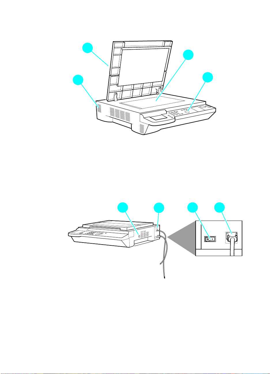
Overview
2
1
2
4
Figure 1. Copy module front left
1 Copyboard cover
2 Copyboard glass
3 Control panel
4 Power supply cooling fan air inlet
2
2
2
3
2
Figure 2. Copy module front right
1 Control key switch
2 Power supply cord connector
3 Rear power switch
4 Printer power cord connector
26 Chapter 1 - Product information EN
2
2
2 2
3 41
Page 29

2
2
2 2
4 5
2
6
2
3
Figure 3. Copy module cross-section
1 Number 1 mirror
2 Number 2 mirror
3 Number 3 mirror
4 Scanning lamp
5 Lens
6 Charge-coupled device (CCD)
2
1
EN Copy module 27
Page 30

Automatic document feeder (ADF)
The ADF is not part of the standard MFP bu ndle. It can be ordered as
an option.
Features
The ADF can identify the size of an original in terms of its length
(feeding direction) and width for communication to its host computer.
Features include:
l 24 copies per minute
l circulating, auto-duplexing pickup me thod
l communication with copier using interprocess communication
(IPC)
28 Chapter 1 - Product information EN
Page 31

Specifications
Electrical
Table 6. Electrical specifications—ADF
Power supply 24 Vdc (from the copy module)
Maximum power consumption Less than 170 W
Physical
Table 7. Physical specifications—ADF
Weight Approximately 14.8 kg (32.6 lb)
Weight does not include the document output
tray.
Dimensions Width: 641 mm (25.2 in)
Height: 152 mm (6.0 in)
Depth: 508 mm (20.0 in)
Dimensions do not include document output
tray.
Supported media
Table 8. Supported media—ADF
Sizes Weights Capacity
A5, B5, A4, Letter, Legal 50 to 105 g/m
B4, A3, 11 by 17, Legal 50 to 105 g/m
2
2
50 sheets
25 sheets
ADF media selection guidelines
Do not use the following as originals in the ADF:
l transparencies, or paper with an opacity of 80% or less
l carbon-backed sheets
l sheets with paste-ups or binding
l sheets with cut-outs, holes, or tears
l sheets with a clips, staples, or glue
l sheets with curling, wrinkling, or creasing
CAUTION Do not feed the same original more than once, to protect against
damage.
EN Automatic document feeder (ADF) 29
Page 32

Overview
2 2
1 2 4
2
5
Figure 4. Automatic document feeder
1 Upper cover
2 Side guide
3 Last-page detector
4 Original-set indicator
2
6
2
2
7 8
2
3
5 Document tray
6 Sub-tray
7 Body cover
8 Document output tray
2
30 Chapter 1 - Product information EN
Page 33

2
1
2
2
2 2 2 2
4 5 6 7
2
3
2
13
2
8
2
9
22
Figure 5. Automatic document feeder cross-section
1 Reversing roller
2 Paper deflecting plate
3 Feeding roller (separation
function)
4 Separation belt (feeding
function)
5 Pre-separation guide
6 Delivery/pick-up roller
7 Paper retaining plate
121415
22
11
8 Pick-up roller
9 Delivery roller
10 Feeding belt link roller
11 Retaining rolls
12 Feeding belt
13 Paper stopper plate
14 Feeding belt drive roller
15 Registration roller
2
10
EN Automatic document feeder (ADF) 31
Page 34

Side high-capacity input (side HCI)
Features
l holds up to 1,000 sheets of 20-pound (lb) media
l supports media weights of 64 g/m
accommodates either letter- or A4-size media
l
Specifications
Environmental
Table 9. Operating conditions—side HCI
Temperature 10° to 32.5° C (50° to 90.5° F)
Humidity 20% to 80% RH
Atmospheric pressure 786 to 1013 hPa (560 to 760 mm Hg)
Electrical
2
to 105 g/m
2
Table 10. Electrical specifications—side HCI
Power supply:
110 V units
220 V units
Power consumption Less than 22 W
100 to 120 Vac (50/60 Hz)
220 to 240 Vac (50 Hz)
Physical
Table 11. Physical specificat ions—side HCI
Weight Approximately 18.5 kg (40.8 lb)
Dimensions (mm) Width: 317 mm (12.5 in)
Height: 280 mm (11.0 in)
Depth: 571 mm (22.5 in)
32 Chapter 1 - Product information EN
Page 35

Overview
2
2
2
3
Figure 6. Front of side HCI
1 Upper right cover
2 Paper-size selection tab
3 User LED
2
1
2
4
2
5
Figure 7. Rear of side HCI
4 Interface connector
5 Power receptacle
EN Side high-capacity input (side HCI) 33
Page 36

2
4
2
1
2
2
2
3
2
5
Figure 8. Cross-section of side HCI
1 Feed roller
2 Pick-up roller
3 Paper-size limit panel
4 Separation roller
5 Lifter
34 Chapter 1 - Product information EN
Page 37

Model and serial numbers
The serial number on the HP Color LaserJet 8550MFP is t he pr imar y
identification number for this MFP bundle. The serial number is
located on the back of the print engine.
Accessories also have their own unique serial numbers, which are
located on the back of each accessory.
Safety and regulatory information
Declaration of conformity
according to ISO/IEC Guide 22 and EN 45014
Manufacturer’s Name:
Manufacturer’s Address:
declares, that the product
Product Name:
Model Number:
Product Options:
conforms to the following Product Specifications:
Safety: IEC 950:1991+A1+A2+A3+A4 / EN 60950:1992+A1+A2+A3+A4+A11
EMC: CISPR 22:1997 / EN 55022:1998 Class A
Supplementary Information:
The product herewith complies with the requirements of the EMC Directive 89/336/EEC and the Low Voltage
Directive 73/23/EEC, and carries the CE-Marking accordingly.
1
The product was tested in a typical configuration with Hewlett-Packard Personal Computer Systems.
2
This Device complies with Part 15 of the FCC Rules. Operation is subject to the following two Conditions:
(1) this device may not cause harmful interference, and (2) this device must accept any interference received,
including interference that may cause undesired operation
June 17, 1999
For Regulatory Topics ONLY, contact:
Australia Contact: Product Regulations Manager, Hewlett-Packard Australia Ltd., 31-41 Joseph
European Contact: Your Local Hewlett-Packard Sales and Service Office or Hewlett-Packard
USA Contact: Product Regulations Manager, Hewlett-Packard Company, PO Box 15, Mail Stop
IEC 825-1:1993 +A1/EN 60825-1:1994 +A11 Class 1 (Laser/LED)
EN 61000-3-2:1995
EN 61000-3-3:1995
EN 55024:1998
FCC Title 47 CFR, Part 15 Class A
AS / NZS 3548:1995
Street, Blackburn, Victoria 3130, Australia
GmbH, Department HQ-TRE / Standards Europe, Herrenberger Straße 110-140,
D-71034 Böblingen, (Fax: +49-7031-14-3143)
160, Boise, Idaho 83707-0015, (Phone: 208-396-6000)
Hewlett-Packard Company
11311 Chinden Boulevard
Boise, Idaho 83714-1021
USA
Color LaserJet 8550MFP Accessories
C7836A, C7837A, and C7839A
All
1
2
/ ICES-002, Issue 2
EN Model and serial numbers 35
Page 38

FCC regulations
This equipment has been tested and found to comply with the limits
for a Class B digital device, pursuant to Part 15 of the FCC rules.
These limits are designed to provide reasonable protection against
harmful interference in a residential installation. This equipment
generates, uses, and can radiate radio frequency energy. If it is not
installed and used in accordance with the instructions, it may cause
harmful interference to radio communicati ons. However, there is no
guarantee that interference will not occur in a particular installation. If
this equipment does cause harmful interference to radio or television
receptions, which can be determined by turning the equipment off
and on, the user is encouraged to try to correct the interference by
one or more of the following measures:
l Reorient or relocate the receiving antenna.
l Increase separation between equipment and receiver.
l Connect equipment to an outlet on a circuit different from that to
which the receiver is located.
l Consult your dealer or an experienc ed radio/TV technician.
Note Any changes or modifications to the printer that are not expressly
approved by HP could void the user’s authority to operate this
equipment.
Use of a shielded interface cable is required to comply with the Class
B limits of Part 15 of FCC rules.
36 Chapter 1 - Product information EN
Page 39

2
Service approach
Chapter contents
Service approach overview . . . . . . . . . . . . . . . . . . . . . . . . . . 39
Parts and supplies . . . . . . . . . . . . . . . . . . . . . . . . . . . . . . . . . 39
Ordering . . . . . . . . . . . . . . . . . . . . . . . . . . . . . . . . . . . . . . . . . 40
Obtaining related documentation and software . . . . . .40
Ordering consumables . . . . . . . . . . . . . . . . . . . . . . . . . 41
Ordering FRUs . . . . . . . . . . . . . . . . . . . . . . . . . . . . . . . 41
Parts exchange program . . . . . . . . . . . . . . . . . . . . . . .41
Technical assistance . . . . . . . . . . . . . . . . . . . . . . . . . . . . . . . 42
List Server . . . . . . . . . . . . . . . . . . . . . . . . . . . . . . . . . . 42
HP ASAP . . . . . . . . . . . . . . . . . . . . . . . . . . . . . . . . . . . 42
HP FIRST. . . . . . . . . . . . . . . . . . . . . . . . . . . . . . . . . . . 43
Dealer Response Line . . . . . . . . . . . . . . . . . . . . . . . . .44
HP Software Distribution Center. . . . . . . . . . . . . . . . . . 44
HP Direct . . . . . . . . . . . . . . . . . . . . . . . . . . . . . . . . . . . 44
Customer Support Sales Center. . . . . . . . . . . . . . . . . .44
Parts identification . . . . . . . . . . . . . . . . . . . . . . . . . . . . 44
Customer Information Centers . . . . . . . . . . . . . . . . . . . 44
HP Customer Care Centers (CCC) . . . . . . . . . . . . . . . 45
Warranty. . . . . . . . . . . . . . . . . . . . . . . . . . . . . . . . . . . . . . . . .46
EN Chapter contents 37
Page 40

38 Chapter 2 - Service approach EN
Page 41

Service approach overview
The HP Color LaserJet 8550MFP has a one-year, next-day, onsite
warranty from HP to the customer. An in-field service strategy based
on field-replaceable units (FRUs) applies to all devices of the HP
Color LaserJet 8550MFP system (print engine, copy module, and
side HCI).
The ADF under warranty will be first be serviced by a field technician
who will troubleshoot, clean, and adjust the unit. The field technician
can also replace the feeding belt, if necessary. If these measures fail
to correct the problem, the ADF be replaced as a whole-unit
exchange.
Parts and supplies
Field-replaceable and accessory part numbers are found in chapter 8
of this manual. Use only accessories specifically designed for this
printer. Accessories can be ordered from an authorized service or
support provider. Replacement parts can be ord ered from HP’s
Service Materials Organization (SMO) or Support Materials Europe
(SME).
EN Service approach overview 39
Page 42

Ordering
The following table lists information for ordering from SME, SMO, and
the HP Distribution Center (HPD).
Table 12. Ordering parts
Organization Address Phone
SMO (Service Materials
Organization)
SME (Support Materials Europe) Hewlett-Packard Company
HPD (HP Distribution Center) (805) 257-5565
Obtaining related documentation and
software
Hewlett-Packard Company
Support Materials Organization
8050 Foothills Blvd.
Roseville, CA 95678
Support Materials Europe
Wolf-Hirth Strasse 33
D-7030 Böblingen, Germany
(800) 227-8164
(U.S. only)
(49 7031) 14-2253
(805) 257-6995 Fax
To order related documentation and software, contact SMO or SME
at the numbers listed on the previous page.
For information through the World Wide Web, visit the following
websites:
Table 13. Technical support websites
HP Customer Care Online
Software drivers, support documentation, and
answers to frequently asked questions
HP Technical Training
(North America)
Classes and schedules
Parts
Parts information
http://www.hp.com/go/support
http://www.hp.com/go/resellertraining
http://outfield.external.hp.com/spi/
welcom.htm
40 Chapter 2 - Service approach EN
Page 43

Ordering consumables
Consumable parts and accessories are available directly from
Hewlett-Packard at the following numbers:
l U.S.: (800) 538-8787
l Canada: (800) 387-3154
(in Toronto: (416) 671-8383)
l United Kingdom: 0734-441212
l Contact your local HP Parts Coordinator for other local phone
numbers.
To find a dealer near you (or if the local dealer is temporarily out of
stock), call the HP Customer Information Center at (800) 752-0900.
Ordering FRUs
This printer is designed to be repaired by replacing FRUs. Part
numbers are located in chapter 8 of this manual and can be ordered
from SMO or SME (see page 40).
Parts exchange program
HP offers remanufactured assemblies for selected parts. These are
identified in chapter 8 and can be ordered thro ugh SMO or SME ( see
page 40).
EN Ordering 41
Page 44

Technical assistance
List Server
A list server is an e-mail program that allows users to subscribe to
certain mail lists by sending e-mail to the server. The list server
allows HP LaserJet Technical Marketing to make the support
community aware of new or urgent information by sending
information to subscribers.
l To subscribe to hardware-related information, send e-mail to:
subscribe-CLJ8500/8550-HW@chsdes1.boi.hp.com
l To subscribe to software-related information, send e-mail to:
subscribe-CLJ8500/8550-SW@chsdes1.boi.hp.com
Once you subscribe, you will receive more information about the
benefits of the list server as well as additional instruction about how t o
use the list server.
HP ASAP
HP ASAP (Automated Support Access Program) provides free
technical support information 24 hours a day, 7 days a week. The
ASAP system includes HP FIRST, explained below. The ASAP
service at (800) 333-1917 (U.S.) requires a touch-tone phone.
42 Chapter 2 - Service approach EN
Page 45

HP FIRST
HP FIRST (Fax Information Retrieval Support Technology) is a
phone-in fax service that provides technical information for
HP LaserJet end-users and service personnel. Receiving a fax
requires a type-3 facsimile machine or fax card. Service-re lated
information includes:
l service notes (HP Authorized Dealers)
l Product Data Sheets (PDS)
l Material Safety Data Sheets (MSDSs)
l typeface and accessory information
l printer support software information
l toner information
l driver request form and Software Matrix
HP FIRST, U.S.
Call the U.S. HP ASAP system at (800) 333-1917 and follow the
voice prompts to enter HP FIRST.
HP FIRST, Europe
Call HP FIRST at one of the following European numbers:
l U.K.: 0800-96-02-7 1
l Belgium: 078-111906 (Dutch)
l Switzerland: 155-1527 (German)
l Netherlands: 06-0222420
l Germany: 0130-810061
l Austria: 0660-8128
For English service outside the countries listed above, call
(31) 20-681-8192.
EN Technical assistance 43
Page 46

Dealer Response Line
For further technical assistance on pre/post sales and service
support, HP dealer service-authorized personnel can contact the
Dealer Response Line.
(800) 544-9976 (U.S. only)
(800) 363-6584 (Canada)
HP Software Distribution Center
For printer drivers and application note orders:
(805) 257-5565
HP Direct
For supplies and accessories orders:
(800) 538-8787 U.S. only
Customer Support Sales Center
For existing hardware and software service agreements:
(800) 386-1115 U.S. only
For price quotations for or purchase of new hardware or software
agreements:
(800) 743-8305 U.S. only
Parts identification
For service part number identification:
(916) 783-0804
Customer Information Centers
For further technical assistance, service-authorize d HP and dealer
service personnel can contact th e Hew l et t-Packard Customer
Information Center at (800) 752-0900 in North America.
44 Chapter 2 - Service approach EN
Page 47

HP Customer Care Centers (CCC)
HP representatives are available to answer technical questions at no
charge for a period equivalent to the original HP hardware warranty
period.
Questions regarding operating systems such as MS-DOS®, UNIX®,
or network configuration operating systems cannot be answered by
the Customer Care Center, and should be referred to your dealer.
Note Each time you call the HP Customer Care Centers, you will be asked
to provide the printer serial number and the original date of purchase.
U.S. CCC
The CCC can be reached at (208) 323-2551 and is available
weekdays from 6:00 A.M. to 6:00 P.M. Mounta in Tim e .
European Customer Care Center (ECCC)
The ECCC can be reached at 31-0-20-605-0505 a nd is available
weekdays from 8:30 A.M. until 6:00 P.M. Central European Time.
Multilingual customer-support representative s are available to answer
questions.
Canadian Customer Care Center (CCCC)
The CCCC at (905) 206-4663 is available weekdays from 8:00 A.M.
until 8:00 P.M. Eastern Time. French- and English-speaking
customer-support representatives are available to answer que stions.
EN Technical assistance 45
Page 48

Asia Pacific region Customer Care Centers
Table 14. Asia Pacific region Customer Care Cen ters
Country Phone Hours of operation
Australia + 61 3 8877 8000 9:00 A.M. to 5:00 P.M., Monday through Friday
China + 86 (0)10 6564 5959 8:30 A.M. to 5:30 P.M., Monday through Friday
Hong Kong 800 96 7729 8:30 A.M. to 5:30 P.M., Monday through Friday
India + 91 11 682 6035 9:30 A.M. to 5:30 P.M., Monday through Friday
Indonesia +62 (21) 350 3408 8:00 A.M. to 5:00 P.M., Monday through Friday
Japan + 81 3 3335 8333 9:00 A.M. to 12:00 noon and 1:00 P.M. to 5:00 P.M.,
Monday through Friday
Korea, Republic of +82 (2) 3270 0700 8:30 A.M. to 5:30 P.M., Monday through Friday
(outside Seoul only) 080 999 0700 8:30 A.M. to 5:30 P.M., Monday through Friday
Malaysia +60 (3) 295 2566 8:30 A.M. to 5:30 P.M., Monday through Friday
Penang 1 300 88 00 28 8:30 A.M. to 5:30 P.M., Monday through Friday
New Zealand +64 (9) 356 6640 9:00 A.M. to 5:00 P.M., Monday through Friday
Philippines + 63 (2) 867 3551 8:30 A.M. to 5:30 P.M., Monday through Friday
Singapore +65 272 5300 8:30 A.M. to 5:30 P.M., Monday through Friday
Taiwan + 886 (2) 2717 0055 8:30 A.M. to 6:00 P.M., Monday through Friday
Thailand +66 (2) 661 4000 8:30 P.M. to 5:30 P.M., Monday through Friday
Vietnam +84 (0) 8 823 4530 8:00 A.M. to 5:00 P.M., Monday through Friday, and
8:00 A.M. to 12:00 noon on Saturday
Warranty
The warranty outlines specific legal rights. Customers might also
have other rights that vary from area to area. Refer to the user’s guide
for further warranty information.
46 Chapter 2 - Service approach EN
Page 49

3
Operational overview
Chapter contents
Control panel. . . . . . . . . . . . . . . . . . . . . . . . . . . . . . . . . . . . . 49
Copy module functionality . . . . . . . . . . . . . . . . . . . . . . . . . . . 51
User mode. . . . . . . . . . . . . . . . . . . . . . . . . . . . . . . . . . 52
Automatic gradation adjustment . . . . . . . . . . . . . . . . . 57
Cold reset . . . . . . . . . . . . . . . . . . . . . . . . . . . . . . . . . . 57
Original-set indicator (ADF) . . . . . . . . . . . . . . . . . . . . . 58
Warnings and actions . . . . . . . . . . . . . . . . . . . . . . . . . 58
Self-diagnostic messages . . . . . . . . . . . . . . . . . . . . . . . . . . . 59
Service mode . . . . . . . . . . . . . . . . . . . . . . . . . . . . . . . . . . . . 60
Overview . . . . . . . . . . . . . . . . . . . . . . . . . . . . . . . . . . . 60
Navigating service mode screens . . . . . . . . . . . . . . . . 63
Copier, display mode (DISPLAY) . . . . . . . . . . . . . . . . 65
Copier, I/O mode (I/O) . . . . . . . . . . . . . . . . . . . . . . . . . 77
Copier, adjust mode (ADJUST) . . . . . . . . . . . . . . . . . . 83
Copier, run/check mode (FUNCTION). . . . . . . . . . . . . 93
Copier, machine settings (OPTION) mode . . . . . . . . . 98
Copier, test print mode (TEST) . . . . . . . . . . . . . . . . . 108
Copier, counter mode . . . . . . . . . . . . . . . . . . . . . . . . 111
Feeder . . . . . . . . . . . . . . . . . . . . . . . . . . . . . . . . . . . . 114
EN Chapter contents 47
Page 50

48 Chap te r 3 - Op er at ion a l over vie w EN
Page 51

Control panel
2
1
2
2
2
3
2
13
2
14
2
15
2
16
2
17
2
18
2
2
8
4
Figure 9. Copy module control panel
2
6
2
2
5
1 System switch—switch between the copy module user interface
2 Status indicators:
3 Screen contrast dial—adjust the contrast of the liquid crystal
4 Reset key—return to standard copying mode; also use to back
5 Guide key—display context-sensitive help screens (functions,
7
and the print system screen; also use to exit Power Save mode
• copying—glows green to indicate that copying is under way
• error—flashes orange to indicate the absence of media,
media jam, or absence of toner; glows orange to indicate a
fault
• data—glows green to indicate that data is being output
• error (after “options”)—flashes orange to indicate a printer
error, the absence of media, media jam, or absence of toner
display (LCD) (clockwise darkens the screen, counter-clockwise
lightens the screen)
out of menus without making changes
how to operate)
2
9
2
10
2
11
2
12
2
19
2
20
6 User mode key—start or end user mode, and check common
settings, copy module settings, timer settings, adjust/clean
settings, and counter readings
7 Interrupt key—make an interrupt copy
EN Control panel 49
Page 52

8 Touch panel display—display settings screen according to
system functions
9 Keypad—enter numerical values, such as copy counts
10 ID key—start ID mode with the ID key and enter a user ID or
password on the keypad; also use to lock the copy module
11 Start key—begin to co py
12 Stop key—stop continuous copying
13 Clear key—initialize numeric values, such as copy counts
14 ACS key—enable and disable black-and-white/color auto
identification
15 Full-color key—select four-color (full-color) mode
16 Black key—select black (mono-color) mode
17 Save power key—enable and disable Power Save mode
18 Clip holder—a recessed area for paperclips
19 Control panel power switch—turn power to the copy module on
and off
20 Pilot lamp—stays lit when there is power to the copy module
50 Chap te r 3 - Op er at ion a l over vie w EN
Page 53

Copy module functionality
Table 15. Copy module functionality
Mode Description
Auto paper select Measures the size of the original and the reduction/enlargement percentage,
and selects the appropriate size for copies.
Auto enlarge/reduce Enlarges/reduces to suit the selected paper size.
Full image Reduces images slightly to avoid copying in the unprintable area.
Zoom Enlarges/reduces images to preset or selected percentages.
X/Y zoom Enables specification of different ratios for X and Y directions in percentages.
Enlarged page
separation
Text/photo/map Adjusts copy algorithms to best match the type of original.
Auto start Starts copying automatically after the warm-up/calibration process from
Double-sided
(requires duplexing unit)
Interrupt copying Allows interruption and resumption of continuous copying for quick copies of
Color auto recognition
(ACS)
Page separate Print left and right pages of a book on separate pages.
Book frame erase Erases shadows from originals.
Original frame erase Erases the shadow and frames along the sides and the middle of a copy that
Hole image erase Erases the shadow of holes on a copy.
Second-side elimination Blocks the image on the back of a double-sided original on a copy.
Shift Shifts images to the center (or corner) of a copy.
Bind margin Shifts the image of the original to create a blank width of zero to 20 mm along
Sheet frame erase Creates a blank width (7 mm) along the sides of a copy to prevent soiling or
Reduce page compose Requires an ADF.
Enlarge page compose Divides the image of a single original into several copies (1 to 2, or 1 to 4).
ID Enables copying only in response to an appropriate ID number or password.
Divides an image into several pages for output.
* text/photo/map (default) * print photo
* photo * black-and-white text
power-on or jam removal.
Makes double-sided copies of two single-sided copies, or makes double-
sided copies of the left and right pages of an original (page separation).
different originals.
Automatically identifies a color or a black-and-white original.
is larger than the original.
the side of the copy (left/right/top/bottom bind).
line images on the copy.
EN Copy module functionality 51
Page 54

User mode
The copy module provides an administrative-functions menu that
allows for customized defaults to suit users’ needs. Four
administrative menus are available when is pressed.
l Common settings
l Copy module settings
l Timer settings
l Adjustment/cleaning
The administrative-functions key also allows users to check the
readings of six software counters from the control panel display.
52 Chap te r 3 - Op er at ion a l over vie w EN
Page 55

Common settings
Table 16. Common settings
Name Description Remarks
Buzzer Enables and disables the input
sound, alarm sound, or job sound.
ON: enable
OFF: disable
Cassette auto
select
Black text auto
density adjust
Priority on photo/
text in black mode
for text/photo/map
Save power Selects a rate of saving for the copy
Enables and disables auto selection
(auto paper selection and auto
cassette change) for each cassette
(including the side HCI).
ON: enable
OFF: disable
In black-text mode, selects “priority
on image quality,” in which prescanning is enabled, or “priority on
speed,” in which there is no prescanning.
In black mode of text/photo/map
mode, selects “text original” or “photo
original” for image quality. In “priority
on text original,” text is reproduced
more faithfully. In “priority on photo
originals,” photographs are
reproduced more faithfully.
module in power save mode:
10%: saving at 10%
25%: saving at 25%
50%: saving at 50%
No recovery time: no saving
Factory setting: ON
Factory setting:
cassette 1/2, ON;
multifeeder, OFF
Factory setting:
priority on speed
Factory setting:
priority on photo original.
The “rate of saving” is the
rate of saving in relation to
the copy module’s total
power consumption.
Factory setting: 10%
Inch input Enables and disables input in inches
on screen designed for metric inputs
(shift width or bind width).
ON: enable
OFF: disable
EN Copy module functionality 53
Factory setting: OFF.
Page 56

Copy module settings
Table 17. Copy module settings
Name Description Remarks
Preference key Allows for up to two commonly-used
special functions to be displayed as
buttons on the main menu.
Standard mode Stores copy module standard mode
settings selected at power-on or in
response to the Reset key being
pressed.
Settings reset Initializes the items of the copy
module settings to factory settings.
Factory settings: none
Factory setting:
copy count: 1
paper select: auto
density: auto
original type: text/photo/map
54 Chap te r 3 - Op er at ion a l over vie w EN
Page 57

Timer settings
Table 18. Timer settings
Name Description Remarks
Auto clear time Automatically returns the touch-panel
display to standard mode if no
operation takes place for a set time
after the end of key operation. Set the
time to between zero and nine
minutes in one-minute increments.
Auto save power
time
Shift to low power
time
Auto power-off time Automatically turns off the copy
Automatically puts the copy module in
save power mode if no operation
takes place for a set time after the
end of copying or key operation. Set
the time to one, two, five, 10, 20, or
30 minutes, or to one to eight hours in
one-hour increments.
Automatically puts the copy module
into low-power mode if no operation
takes places for a set time after the
end of copying or key operation. Set
the time to 30 minutes or to one to
eight hours in one-hour increments.
module if no operation takes place for
a set time after the end of copying or
key operation. Turn the setting off or
set the time to one to 24 hours in onehour increments.
Factory setting: 2 minutes
Factory setting: 30 minutes
Factory setting: one hour
In low power mode, the
fusing assembly is deprived
of power in specific intervals.
Factory setting: two hours
The setting is changed to
“off” at installation.
EN Copy module functionality 55
Page 58

Adjustment/cleaning
Table 19. Adjustment/cleaning
Name Description Remarks
Zoom fine
adjustment
Exposure
recalibration
Auto gradation
adjustment
Feeder cleaning Feed ten blank sheets of paper
Make fine adjustments to correct
small discrepancies between the
original image and the copy image
made in Direct. For X (left/right) and Y
(front/back), adjustment is possible
between -1.0% and +1.0%.
Correct differences in density
between the original image and a
copy image that has been made with
the manual density control set at the
standard (median) value. Adjust the
density correction to any of five
settings.
Correct poor color balance caused by
discrepancies in fine adjustment or
density adjustment.
through the optional ADF to pick up
loose toner and other contaminants.
Factory setting: 0.
Factory setting:
standard (median)
See the section that follows
for information about auto
gradation adjustment.
56 Chap te r 3 - Op er at ion a l over vie w EN
Page 59

Automatic gradation adjustment
To change the automatic gradation adjustment
1 Press the key.
2 Press A
3 Press A
4 Press T
DJUSTMENT/CLEANING.
UTO GRADATION ADJUSTMENT.
EST PRINT 1. The message PRINTING TEST PRINT 1
appears on the copy module touch screen display.
5 Place the page from Test Print 1 on the copy module glass, face-
down, with the black portion of the page aligned with the orange
arrow, and then press S
the page was placed on the glass correctly. If not, C
P
LACE THE TEST PRINT ON THE GLASS appears; adjust the
CAN. SCANNING appears on the display if
ORRECTLY
placement of the page and press OK.
6 After the page has been scanned, remove it from the copy
module glass.
7 Repeat steps 4 through 6 for Test Prin t 2.
8 Repeat steps 4 through 6 for Test Prin t 3.
9 When scanning of Test Print 3 is complete, S
CAN IS COMPLETE
appears on the display for approximately two seconds.
Cold reset
To perform a cold reset on the print engine por tio n of the HP Color
LaserJet 8550MFP, see the HP Color LaserJet 8500/8550 Printer
Family Service Manual.
Cold reset on the copy module is useful in three circumst an ce s:
l after replacement of the firmware dual inline memory modules
(DIMM)
l after replacement of the reader controller printed circuit board
(PCB)
l if a system settings password has been set and forgotten
For more information about cold resets, see page 96.
EN Copy module functionality 57
Page 60

Original-set indicator (ADF)
The original-set indicator turns on when an original is placed on the
document tray, and flashes when an original jams.
1 If the original is A3 or 11-by-17 inch in feeding length, open the
original sub tray.
2 Set the side guide to suit the size of the original.
Note The side guide lock must be removed if the width of the original is larger
than 297 mm (A4/A3). For details, see “To remove the side guide lock”
on page 382.
3 Place the originals with the first page on top.
4 As needed, set the appropriate copying mode on the copy
module.
5 Press the copy module’s Copy Start key.
Warnings and actions
If the original-set indicator flashes while an original is being fed,
suspect a jam and perform the following:
1 Remove the originals from the document tray.
2 Open the upper cover, and remove the jam. Then, open the ADF
to reset the warning. (If any original is on the copyboard glass,
remove it.)
CAUTION If the jam is in the copy module, the copy module will run jam recovery
mode and will automatically set the originals. Do not open the ADF to
reset.
3 Set the originals in correct order, and set the stack in the ADF.
58 Chap te r 3 - Op er at ion a l over vie w EN
Page 61

Self-diagnostic messages
If a self-diagnostic (error) message appears, see the instructions on
the touch panel display.
If there is no message, but the HP Color LaserJet 8550MFP fails to
make copies, there might be an error in the p rinter unit. Follow the
instructions on the printer control panel display.
Table 20. Self-diagnostic (error) messages
Message Cause Solution
PAPER HAS JAMMED IN
T
HE “_____” AREA.
R
EMOVE THE JAMMED
P
APER.
R
ETURN PG.1 TO THE TOP
A
ND PRESS THE START
K
EY AGAIN.
R
EPLACE THE DRUM. The drum cartridge is near the end of
An original or copy media jam has
occurred, halting any print or copy
jobs.
Copying was stopped because of a
problem in the optional ADF.
its life cycle.
S
ET THE DRUM
C
ARTRIDGE.
ET THE FUSER UNIT. The fuser unit is not installed correctly. Reinstall the fuser unit.
S
ET THE INTERMEDIATE
S
T
RANSFER DRUM.
OLOR> TONER NEEDS
<C
T
O BE REPLACED.
The imaging drum is not installed
correctly.
The intermediate transfer drum is not
installed correctly.
There is a small amount of the toner
remaining as indicated in the touch
panel display.
R
EPLACE THE <COLOR>
T
ONER CARTRIDGE.
There is only a small amount of the
toner remaining as indicated in the
touch panel display, halting any print
or copy jobs.
L
OAD PAPER. The copy module has run out of
media, halting any print or copy jobs.
L
OAD LTRR-SIZE PAPER. Copy media of the appropriate size
and rotation is not placed in the
selected media input tray.
A
DJUSTING...
W
AIT A MOMENT, THEN
S
ET THE STACK BYPASS
S
IZE AGAIN
The copy module is making internal
operational adjustments.
See the location (“_____”) and
follow the removal procedures
described in the screen for
instructions to clear the jammed
media.
Rearrange the originals in page
order from the first page in the
optional ADF, and then press the
Start key.
Replace the drum kit.
Reinstall the imaging drum.
Reinstall the intermediate transfer
drum.
Prepare the toner cartridge
indicated in the touch panel display.
Replace the toner cartridge
indicated in the copy module touch
panel display.
Load media into one of the input
trays.
Place copy media of the indicated
size and rotation in the input tray.
If the Start key is pressed while the
message is shown, copying will be
performed on the displayed copy
media size.
Remove the media from Tray 1
(stack bypass), wait one minute,
and the replace the media in the
tray.
EN Self-diagnostic messages 59
Page 62

Service mode
Note You cannot start service mode when the “Wait” message appears on
the user screen after the power is turned on. Start service mode when
the “Wait (Select Auto Start)” or “Enter Group ID and I D No.” message
appears.
Overview
The copy module's service mode is divided into two major items,
each with its own initial screen:
l COPIER (copier service screens begin on page 65)
l FEEDER (feeder service screens begin on page 114)
Each of these major items consists of sub-items, called “Level 1”
items:
Table 21. Service mode sub-items
Initial screen Level 1 menu Mode
COPIER DISPLAY Control display mode
I/O I/O mode
ADJUST Adjust mode
FUNCTION Run/check mode
OPTION Settings mode
TEST Test print mode
COUNTER Counter mode
FEEDER DISPLAY Control display mode
ADJUST Adjust mode
FUNCTION Run/check mode
OPTION Settings mode
60 Chapter - 3 Operational overview EN
Page 63

To start service mode and make selections
1 Press the administrative-functions key ( ) on the control
panel.
2 Press the 2 and 8 on the keypad simultaneously.
3 Press again. The display changes to the screen shown in
figure 10.
Figure 10. Service mode initial scree n
4 Select an item on the touch panel. The screen for the selected
item appears.
To end service mode
Press the Reset key to return to the service mode initial screen. Press
the Reset key again to end service mode and retu rn to the User
screen.
EN Service mode 61
Page 64

Backing up copy module service settings
Figure 11 shows the label attached behind the lower f ront cover of the
copy module.
Figure 11. Service label (inside the lower front cover of the copy module)
The copy module is adjusted at the factory, and the adjustment
settings are recorded on this label.
l If you have replaced the reader controller PCB, the firmware
DIMM, or the dc controller PCB (on the printer), you must reenter
these numbers in service mode.
l If you have replaced the standard white plate , you must enter the
new values found on the new standard white plate into service
mode (W-PLT-X, W-PLT-Y, and W-PLT-Z).
l If you have replaced the CCD unit, you must enter th e new values
found on the new CCD into service mode (AL-RG and AL-GB).
62 Chapter - 3 Operational overview EN
Page 65

Navigating service mode screens
The screens are arranged in three layer s :
l initial screen (see figure 10 on page 61)
l Level 1/Level 2 screen
l Level 3 screen
Select one of the two major items on the initial screen (eith er C
or F
EEDER) by pressing the item.
Note Feeder is available only when an optional ADF is attached.
After you press one of the major items, the Level 1/Level 2 screen
appears on the display. Figure 12 shows the Level 1/Level 2 screen
that appears after C
OPIER is selected from the initial screen.
OPIER
Figure 12. Example of a Level 1/Level 2 item screen
l Level 1 items are at the top of the screen. To select a Level 1
item, press an item shown across the top of the screen.
l To select a Level 2 item, select an item shown as white text on a
black background.
EN Service mode 63
Page 66

After a Level 2 item is selected, a Level 3 screen appears. Figure 13
shows the Level 3 screen that appears after C
screen, and D
ISPLAY and VERSION, from the Level 1/Level 2 screen,
OPIER, from the initial
are selected.
If the Level 3 item consists of multiple pages,
N/M appears, with N being the present screen
and M indicating the number of pages.
Figure 13. Example of a Level 3 screen
Press the Level 3 item to select it.
64 Chapter - 3 Operational overview EN
Page 67

Copier, display mode (DISPLAY)
Figure 14. Copier, display mode Level 1/Level 2 screen
Table 22. Copier, display mode menu
Item Description
VERSION Read-only memory (ROM) versions of the PCBs used in
the copy module and accessories
USER Indicates items related to the user screen and the user
interface
ACC-STS Connection status of accessories (only if installed)
CST-STS State of use of cassettes and multifeeder
JAM Log of jams
ERR Log of errors and alarms
CCD Measured readings of the CCD
SENSOR State of sensors (important in servicing)
MISC Miscellaneous other conditions
ALARM-1 Latest alarm for the ADF
EN Service mode 65
Page 68

Table 23. Copier, display mode Level 2 and Level 3 menus
Level 2 item Level 3 item Description
VERSION DC-CON ROM version of the dc controller PCB
R-CON ROM version of the reader controller PCB
PANEL ROM version of the control panel controller PCB. “PANEL xx.yy”
ECO ROM version of the ECP PCB
FEEDER ROM version of the ADF controller PCB (if an ADF is installed)
SORTER ROM version of the sorter driver PCB (not available on the HP
DECK ROM version of the deck controller PCB
OP-CON ROM version of the ACC controller PCB
USER LANGUAGE Selected language
ACC-STS
0 = not connected
1 = connected)
FEEDER Connection status of the ADF (if installed)
SORTER Connection status of the sorter (not available on the HP Color
DECK Connection status of the side HCI (if installed)
EDITOR Connection status of the editor (not available on the HP Color
CARD Connection status of the control card (not available on the HP
DATA-CON Connection status of the copy data controller (not available on
PCB Connection status of various boards
“DC-CON xx.yy/XX.YY”
xx.yy: ROM version that controls the communication between
the video controller (LIPS, PS/PCL) PCB on the dc controller
PCB, controls high voltage, and controls some loads (xx =
version number; yy = R&D number)
XX.YY: Version of the ROM which controls loads on the dc
controller PCB (mechanical workings) (XX = version number;
YY = R&D number)
“R-CON: xx.yy” (xx = version number; yy = R&D number)
(xx = version number; yy = R&D number)
“ECO xx.yy” (xx = version number; yy = R&D number)
“FEEDER xx.yy” (xx = version number; yy = R&D number)
Color LaserJet 8550MFP)
“SORTER xx.yy” (xx = version number; yy = R&D number)
“DECK xx.yy” (xx = version number; yy = R&D number)
“OP-CON xx.yy” (xx = version number; yy = R&D number)
“LANGUAGE xx.yy,zz,aa”
xx (first 2 digits): country code (see table 24)
yy (last 2 digits): language code (see table 25)
zz: destination code
aa: series code (see table 26)
LaserJet 8550MFP)
LaserJet 8550MFP)
Color LaserJet 8550MFP)
the HP Color LaserJet 8550MFP)
(9 = accessories control PCB)
66 Chapter - 3 Operational overview EN
Page 69

Table 23. Copier, display mode Level 2 and Level 3 menus (continued)
Level 2 item Level 3 item Description
CTS-STS
(width of media
in terms of
converted value
or media size)
JAM
(jam history; see
figure 15 on page
71 for screen
setup)
ERR
(error history; see
figure 16 on page
76 for screen
setup)
CCD
(CCD-related
measured
readings)
WIDTH-C1 Media width in cassette 1
WIDTH-C2 Media width in cassette 2
WIDTH-C3 Media width in cassette 3 (supports either a 1,000-sheet side
side HCI or a 200-sheet paper deck)
WIDTH-C4 Media width in cassette 4 (supports only a 2,000-sheet side
HCI)
WIDTH-MF Media width in the multifeeder
WIDTH-DK Media width in the side HCI (supports only a 1,000-sheet side
side HCI)
AA 1 through 50 (lower numbers indicate more recent jams)
E Location (0 = copy module; 1 = ADF)
FFFF Jam code
First two digits indicate the type of jam (see table 29 on page 72)
Last two digits indicate the sensor that detected the jam (table
30 on page 73)
G Location of pickup (see table 31 on page 73)
HHHHHH Soft counter reading at the time of a jam
IIIII Media size.
AA 1 through 20 (higher numbers indicate older errors)
EEEE Error code “Exxx” (to decode error codes, see Chapter 7,
“Troubleshooting”)
FFFF Detail code (if not available, “0000”)
G Location (0 = copy module; 1 = ADF)
TARGET-B Shading target value for blue
TARGET-G Shading target value for green
TARGET-R Shading target value for red
BOF-B Output value of the blue CCD (when the scanning lamp is off)
“BOF-B-xx/yy” (xx = odd-numbered bit; yy = even-numbered bit)
BOF-G Output value of the green CCD (when the scanning lamp is off)
“BOF-G-xx/yy” (xx = odd-numbered bit; yy = even-numbered bit)
BOF-R Output value of the red CCD (for when the scanning lamp is off)
“BOF-R-xx/yy” (xx = odd-numbered bit; yy = even-numbered bit)
EN Service mode 67
Page 70

Table 23. Copier, display mode Level 2 and Level 3 menus (continued)
Level 2 item Level 3 item Description
CCD, continued
(when “0” is set to
C
OPIER > OPTION
> B
ODY > SH-SW)
CCD, continued
(when “1” is set to
OPIER > OPTION
C
> B
ODY > SH-SW)
CCD, continued CCD-TYPE Indicates CCD or analog processor (0 = CCD, 1 = analog)
OFST-OB Offset level (SH-SW = 0) of blue for CCD odd-numbered bits
OFST-OG Offset level (SH-SW = 0) of green for CCD odd-numbered bits
OFST-OR Offset level (SH-SW = 0) of red for CCD odd-numbered bits
OFST-EB Offset level (SH-SW = 0) of blue for CCD odd-numbered bits
OFST-EG Offset level (SH-SW = 0) of green for CCD odd-numbered bits
OFST-ER Offset level (SH-SW = 0) of red for CCD odd-numbered bits
GAIN-OB Offset level (SH-SW = 0) of blue for CCD odd-numbered bits
GAIN-OG Offset level (SH-SW = 0) of green for CCD odd-numbered bits
GAIN-OR Offset level (SH-SW = 0) of red for CCD odd-numbered bits
GAIN-EB Offset level (SH-SW = 1) of blue for CCD even-numbered bits
GAIN-EG Offset level (SH-SW = 1) of green for CCD even-numbered bits
GAIN-ER Offset level (SH-SW = 1) of red for CCD even-numbered bits
POFST-OB Offset level (SH-SW = 1) of blue for CCD odd-numbered bits
POFST-OG Offset level (SH-SW = 1) of green for CCD odd-numbered bits
POFST-OR Offset level (SH-SW = 1) of red for CCD odd-numbered bits
POFST-EB Offset level (SH-SW = 1) of blue for CCD even-numbered bits
POFST-EG Offset level (SH-SW = 1) of green for CCD even-numbered bits
POFST-ER Offset level (SH-SW = 1) of red for CCD even-numbered bits
PGAIN-OB Offset level (SH-SW = 1) of blue for CCD odd-numbered bits
PGAIN-OG Offset level (SH-SW = 1) of green for CCD odd-numbered bits
PGAIN-OR Offset level (SH-SW = 1) of red for CCD odd-numbered bits
PGAIN-EB Offset level (SH-SW = 1) of blue for CCD even-numbered bits
PGAIN-EG Offset level (SH-SW = 1) of green for CCD even-numbered bits
PGAIN-ER Offset level (SH-SW = 1) of red for CCD even-numbered bits
TAR2-B Shading target value for blue
Needed when “1” is set to C
OPIER > OPTION > BODY > SH-SW
(in other words, when the lamp intensity is decreased)
TAR2-G Shading target value for green
Needed when “1” is set to C
OPIER > OPTION > BODY > SH-SW
(in other words, when the lamp intensity is decreased)
TAR2-R Shading target value for red
Needed when “1” is set to C
OPIER > OPTION > BODY > SH-SW
(in other words, when the lamp intensity is decreased)
68 Chapter - 3 Operational overview EN
Page 71

Table 23. Copier, display mode Level 2 and Level 3 menus (continued)
Level 2 item Level 3 item Description
SENSOR SC-HP Output of the scanner home position sensor
(0 = home position, 1 = non-home position)
W-TONER Indicates that the waste toner case is almost full
(0 = normal, 1 = full warning)
DOC-SZ Original size detected by the original size sensor
(xxxx = A4, A3, B4, B5, and so on)
DRUMLIFE Life of the photosensitive drum in the drum cartridge:
0 = normal
1 = warning 1 (70%)
2 = warning 2 (100%, at which point the copy module cannot
ensure normal levels of quality)
4 = memory error
MISC DSNS-ALM The density sensor is faulty on the printer side; indicates that the
Y-OUTRNG Indicates that the value is outside the stable Y image guarantee
M-OUTRNG Indicates that the value is outside the stable M image guarantee
C-OUTRNG Indicates that the value is outside the stable C image guarantee
K-OUTRNG Indicates that the value is outside the stable K image guarantee
ENV-DENS Site environment; checks the temperature and humidity inside
ENV-TR Site environment; checks the temperature and humidity inside
FL-LIFE Life of the scanning lamp (0 = normal, 1 = warning); when end-
ALARM-1 DF Latest ADF error (“00” if no errors)
value is outside the stable image guarantee range for the printer
(0 = normal, 1 = error)
Check the sensors and the condition of the intermediate transfer
drum. If the warning remains, density control will fail, bringing
about gradual deterioration of image quality.
range for the printer unit (0 = normal, 1 = error)
range for the printer unit (0 = normal, 1 = error)
range for the printer unit (0 = normal, 1 = error)
range for the printer unit (0 = normal, 1 = error)
the printer and indicates the environmental range for density
control
0: normal temperature/normal humidity (N/N)
1: high temperature/high humidity (H/H)
2: normal temperature/low humidity (N/L)
3: low temperature/low humidity (L/L)
the printer and indicates the environmental range for transfer
control
0: N/N
1: H/H
2: N/L
3: L/L
of-life is reached, E219 is indicated
EN Service mode 69
Page 72

Copier, display mode, user > language details
Table 24. Country code
Code Country Code Country
IT Italy AU Australia
US North America FR France
SG General DE Germany
GB United Kingdom NL Netherlands
Table 25. Language code
Code Language Code Language
JA Japanese DE German
EN English IT Italian
FR French
Table 26. Series code
Code Configuration Code Configuration
00 AB 02 A
01 Inch 03 All configurations
70 Chapter - 3 Operational overview EN
Page 73

Copier, display mode, jam details
Figure 15. JAM screen
Table 27. JAM screen legend
Item Description
AA 1 through 50 (lower numbers indicate more recent jams)
E Location (0 = copy module; 1 = ADF)
FFFF Jam code
G Location of pickup (see table 31 on page 73)
HHHHHH Soft counter reading at the time of a jam
IIIII Media size.
First two digits indicate the type of jam (see table 29 on page 72)
Last two digits indicate the sensor that detected the jam (table
30 on page 73)
EN Service mode 71
Page 74

Copier, display mode, jam details (continued)
the copy module distinguishes 14 types of jams (including jams in the
duplexing unit). Table 28 below shows the combination of codes.
Table 28. Types of jams
First 2 digits Last 2 digits Jam type
01 01
02
03
04
06
07
08
01 01
03
05
06
08
10 10 Internal residual jam
11 11 Door-open jam
Table 29. First 2 digits of FFFF (type of jam)
Pick-up delay jam 2
Intermediate transfer drum jam
Face-down delivery outlet delay jam
Pick-up delay jam 1
Fusing delivery delay jam
Duplexing feeding assembly delay jam
Reversing assembly delay jam
Delivery long-length paper jam
Face-down delivery outlet stationary jam
Non-default-size paper feeding jam
Fusing delivery stationary jam
Reversing assembly stationary jam
Code Description
00 ADF jam
01 Delay jam
02 Stationary jam
10 Residual jam at power-on
11 Door open/closed during copying
72 Chapter - 3 Operational overview EN
Page 75

Copier, display mode, jam details (continued)
Table 30. Last 2 digits of FFFF (jam sensor)
Code Description Sensor
01 Registration paper sensor PS1
02 Separation sensor PS5
03 Face-down tray delivery sensor PS11
04 Pick-up assembly paper sensor PS17
05 Transparency sensors 1 and 2 PS1801, PS1802
06 Fusing delivery sensor PS1903
07 Duplexing unit paper sensor PS24
08 Reversal paper sensor PS26
10 Separation sensor, face-down tray delivery
sensor, pick-up assembly paper sensor, or
fusing delivery sensor
11 Registration paper sensor, separation sensor,
face-down tray delivery sensor, pick-up
assembly paper sensor, transparency sensors
1 and 2, or fusing delivery sensor
Table 31. G (pick-up position)
PS5, PS11, PS17, or
PS1903
PS1, PS, PS11, PS17,
PS1801, PS1802, or
PS1903
Code Description
1 Cassette 1
2 Cassette 2
3 Cassette 3 (supports the two 500-sheet paper decks and the
2,000-sheet paper deck)
4 Cassette 4 (supports the two 500-sheet paper decks)
8 Multifeeder
9 Duplexing unit (accessory)
EN Service mode 73
Page 76

Copier, display mode, jam details (continued)
Table 32. Pick-up jams
Type of original Sensor Description Code
Original extraction S1, S7 The sensor S7 does not detect the
leading edge of an original 1500
msec after pick-up motor M1 has
turned on and, in addition, the
sensor S1 does not detect an
original.
Pick-up delay S7 The sensor S7 does not detect the
leading edge of an original 1500
msec after the pick-up motor M1
has turned on.
Registration delay S3, S7 The sensor S3 does not detect the
leading edge of an original 350
msec after the sensor S7 has
detected the leading edge of an
original.
Table 33. Detecting jams
Original
placement Sensor Description RF operation Code
Recirculation
lever idle rotation
Pick-up failure S7 The sensor S7 does not detect
Paper overriding
the stopper plate
Different number
of originals after
jam removal
S1 The recirculation lever rotates
idly without coming into contact
with an original immediately after
the recirculation motor (M4) turns
on.
the leading edge of an original in
1500 msec during pick-up.
S7 The original has overridden when
placed.
S3 The number of originals placed
on the document tray has
changed as follows*:
Number at end
Number set on of copying
document tray
Stops operating upon
detection.
The separation belt,
feeding roller, and pickup roller stop
immediately. The ADF
stops after discharging
the preceding originals.
Stops operating upon
detection.
Stops operating upon
detection.
0001
0002
0003
01
03
05
11
74 Chapter - 3 Operational overview EN
Page 77

Table 33. Detecting jams (continued)
Original
placement Sensor Description RF operation Code
Unidentified
number of
originals
Original
extraction
Wrong original
size
Wrong original
size or mixed
original sizes in
reduced page
composition
(Note 1)
S3 The recirculating bar does not fall
below the document tray, not
enabling the detection of the last
original.
Reference:
Normally, the document tray is
capable of holding 50 sheets of
A5, STMT, A4, B5, or Letter; 25
sheets of A3, B4, 279 X 432 mm
(11-by-17-inch), or Legal.
S14 The recirculating drops on the
document tray while an original is
being processed.
S3 The size of the original which is
picked up is not of a default size.
S3 1. The original which has been
picked up is not of a size
supported by reduced image
composition mode.
2. The size of the original which
has been picked up is of a size
different from the first original.
1To reset, remove the originals from the document tray, and open the ADF.
Stops operating after
counting up to 100
sheets.
Stops operating upon
detection.
Stops operating upon
detection.
Stops operating upon
detection.
12
13
14
15
EN Service mode 75
Page 78

Copier, display mode, err details
Figure 16. ERR screen
Table 34. ERR screen legend
Item Description
AA 1 through 20 (higher numbers indicate older errors)
EEEE Error code “Exxx” (to decode error codes, see Chapter 7,
FFFF Detail code (if not available, “0000”)
G Location (0 = copy module; 1 = ADF)
“Troubleshooting”)
76 Chapter - 3 Operational overview EN
Page 79

Copier, I/O mode (I/O)
Figure 17. Copier, I/O mode Level 1/Level 2 screen
Table 35. Copier, I/O mode descriptions
Item Description
DC-CON Input/output state of the CPU on the dc controller PCB
R-CON Input/output state of the CPU on the reader controller
PCB
FEEDER State of the CPU on the feeder control ler PCB
EN Service mode 77
Page 80

Address appears here. Each “x”
in the sequence “xxxxxxxx” next
to the address represents a digit,
with bit 7 the first digit, bit 6 the
second digit, and so on to bit 0,
the last digit.
Figure 18. Copier, I/O mode Level 3 screen example
Level 2
selection
appears here
(DC-CON,
R-CON, or
FEEDER)
78 Chapter - 3 Operational overview EN
Page 81

Table 36. Copier, I/O mode Level 2 and Level 3 menus
Level 3
Level 2
DC-CON
(input ports of the
dc controller
PCB)
(address) Bit Item Description
P001 4 FDOUT Face-down tray delivery sensor (PS11)
(“1” when paper is detected)
3 FXOUTS Fusing delivery sensor (PS1903)
(“1” when paper is detected)
2 SEPS Separation sensor (PS5)
(“1” when paper is detected)
1 FEEDS Pick-up paper sensor (PS17)
(“1” when paper is detected)
0 REGS Registration paper sensor (PS1)
(“1” when paper is detected)
P002 5 SWBKS Duplexing unit reversal paper sensor (PS26)
(“1” when paper is detected)
For bit 5, the door must be closed. Defeat the
door switch to simulate a closed door.
4 DUPPS Duplexing unit paper sensor (PS24)
3 LDECKS Cassette 2 paper sensor (PS1207)
1 UPDECKS Cassette 1 paper absent sensor (PS1208)
0 MPDFS Multifeeder tray last paper sensor (PS19)
P003 1 TMPSNS Temperature and humidity sensor
0 HUMSNS
(“1” when paper is detected)
For bit 4, the door must be closed. Defeat the
door switch to simulate a closed door.
(“1” when paper is detected)
(“1” when paper is detected)
(“1” when no more than one sheet is set)
00: normal temperature/normal humidity
01: high temperature/high humidity
10: normal temperature/low humidity
11: low temperature/low humidity
EN Service mode 79
Page 82

Table 36. Copier, I/O mode Level 2 and Level 3 menus (continued)
Level 3
Level 2
R-CON
(
input/output
state of the
CPU on the
reader
controller PCB)
(address) Bit Item Description
P001 6 --- SW7 of SW1601
5 --- SW6 of SW1601
4 --- SW5 of SW1601
3 --- SW4 of SW1601
2 --- SW3 of SW1601
1 --- SW2 of SW1601
0 --- SW1 of SW1601
P002 7 DSZ4 Original size sensor 4 (PS106)
6 DSZ3 Original size sensor 3 (PS105)
5 DSZ2 Original size sensor 2 (PS104)
4 DSZ1 Original size sensor 1 (PS103)
P003 5 FLPWN Scanning lamp activation
P004 7 FLERR Scanning lamp error signal
(“1” if error)
3 CCIVCONE*Control card connected signal
(“1” when connected)
1 FM4DEC Power supply fan locked signal
(“1” when locked)
0 CBCC Copyboard cover open/close sensor (PS102)
(“1” when closed)
P005 2 KEYSW Control key switch signal
(“1” when on)
P006 7 ACCON Accessories power supply connected signal
(“1” when connected)
6 YON Scanning lamp pre-heat ON signal
5 FLONOUT Scanning lamp ON signal
1 MMIRST LCD control panel rest signal
P008 4 LPHTON Scanning lamp heater ON signal
1 FM4ON Power supply fan (FM4) drive signal
(“1” when rotating)
0 BLON* LCD control panel back-light ON signal
(“1” when on)
P009 2 ASTCNT Copy data control counter signal
1 CCIVCNT Control card counter signal
P013 0 FL_TH Scanning lamp thermistor signal
P022 2 SOFSWON Power soft switch ON signal
(“1” when on)
80 Chapter - 3 Operational overview EN
Page 83

Table 36. Copier, I/O mode Level 2 and Level 3 menus (continued)
Level 3
Level 2
FEEDER
(input ports of the
feeder controller
PCB)
(address) Bit Item Description
P001 3 BDIR Belt motor (M3) rotation direction signal
(“1” when in correct delivery mode)
2 SMPSL Stamp solenoid (SL4) drive
(“1” when on)
1 FLPSL1 Paper deflecting plate solenoid (SL3) drive
(“1” when on)
0 STPSL Stopper plate solenoid (SL1) drive
(“1” when on)
P002 2 SPRS Pick-up sensor (S7)
(“1” when paper is present)
1 EJTS1 Delivery sensor 1 (S6)
(“1” when paper is present)
0 TLIRNS Reversal sensor (S8)
(“1” when paper is present)
P003 5 RSS Recirculation sensor (S14)
(“1” when paper is present)
P004 4 DCTS Pick-up roller sensor (S13)
(“1” when paper is present)
3 ECLK Delivery motor clock sensor (S13)
(alternates “0” and “1” when rotating)
2 RCLK Registration roller clock sensor (S11)
(alternates “0” and “1” when rotating)
1 FCLK ADF motor clock sensor (S9)
(alternates “0” and “1” when rotating)
0 BCLK Belt motor clock sensor (S10)
(alternates “0” and “1” when rotating)
P006 7 SMON Pick-up motor (M1) drive signal
(“1” when on)
6 SMPWM Pick-up motor (M1) speed signal
(“0” or “1” according to speed)
4 FMPWM ADF motor (M2) speed signal
(“0” or “1” according to speed)
3 BMON Belt motor (M3) drive signal
(“1” when on)
2 BMPWM Belt motor (M3) speed signal
(“0” or “1” according to speed)
EN Service mode 81
Page 84

Table 36. Copier, I/O mode Level 2 and Level 3 menus (continued)
Level 3
Level 2
FEEDER,
continued
(address) Bit Item Description
P007 7 WGTSL Paper holding plate solenoid (SL2)
(“1” when on)
6 CL Clutch (CL) drive (”1” when on)
5 BK Brake (BK) drive (”1” when on)
3 ORGLED Original indicator LED (LED101, LED 102)
(“0” when on)
2 RSDRV Recirculation motor (M5) drive signal
(“1” when on)
1 SDIR Pick-up motor (M1) direction signal
(“1” when in top-separation mode)
0 EMPWM Delivery motor (M5) speed signal
(“0” or “1” according to speed)
P008 5 RFC ADF switch (MS1) (”1” when open)
4 UPCC1,
CVRSW
3 EJTS2 Delivery sensor 2 (S12)
2 SW3 on feeder controller PCB
1 SW2 on feeder controller PCB
0 SW1 on feeder controller PCB
P009 1 --- LED2 on feeder controller PCB
0 --- LED1 on feeder controller PCB
P010 7 --- DSW1-8 on feeder controller PCB
6 --- DSW1-7 on feeder controller PCB
5 --- DSW1-6 on feeder controller PCB
4 --- DSW1-5 on feeder controller PCB
3 --- DSW1-4 on feeder controller PCB
2 --- DSW1-3 on feeder controller PCB
1 --- DSW1-2 on feeder controller PCB
0 --- DSW1-1 on feeder controller PCB
Upper cover switch (MS2), Upper cover
sensor (S4) (”0” when upper cover is open)
(“1” when paper is present)
(“1” when pushed)
(“1” when pushed)
(“1” when pushed)
(“0” when on)
(“0” when on)
(“1” when on)
(“1” when on)
(“1” when on)
(“1” when on)
(“1” when on)
(“1” when on)
(“1” when on)
(“1” when on)
82 Chapter - 3 Operational overview EN
Page 85

Copier, adjust mode (ADJUST)
Figure 19. Copier, adjust mode Level 1/Level 2 screen
Table 37. Copier, adjust menu descriptions
Item Description
AE Adjust AE mode
ADJ-XY Adjust the image position
CCD Adjust CCD- and shading-related items
IMG-REG Correct color displacement
DENS Adjust developing density-related items
BLANK Adjust the image margins
PASCAL Execute auto gradation correction control
COLOR Adjust color balance
HV-TR Adjust transfer charging bias output by condition
FEED-ADJ Adjust ADF-related items
MISC Other
EN Service mode 83
Page 86

Table 38. Copier, adjust mode Level 2 and Level 3 menus
Level 2 item Level 3 item Range Description
AE AE-TBL +1 to +9
Standard = 5
BE-TBL +1 to +9 Adjust if the density of the text is too high
ADJ-XY
See the details
after this table on
page 90
CCD W-PLT-X +2000 to
ADJ-X 0 to +32 Moves the image on the copied page
ADJ-Y 0 to +255 Moves the image on the copied page
+11997
W-PLT-Y +2000 to
+11997
W-PLT-Z +2000 to
+11997
A-RG 9 to +9
B-RG 9 to +9
A-GB 9 to +9
B-GB 9 to +9
AL-RG 9 to +9
AL-GB 9 to +9
Adjust if the density of the text is too low (light
text) with priority on speed in AE mode (black-
and-white text mode only). Use higher
settings for darker print.
(dark text), with priority on speed in AE mode
(black-and-white text mode only).
(X direction).
(Y direction).
Standard white plate X signal data.
See the details after this table on page 90.
Standard white plate Y signal data.
Standard white plate Z signal data.
Correct color displacement in sub-scanning
direction dependent on R-G ratio.
Correct color displacement in sub-scanning
direction not dependent on R-G ratio.
Correct color displacement in sub-scanning
direction dependent on G-B ratio.
Correct color displacement in sub-scanning
direction not dependent on G-B ratio.
Correct color displacement in sub-scanning
direction dependent on R-G ratio for the lens
unit.
Note: this number is specified on the CCD
unit.
Correct color displacement in sub-scanning
direction dependent on G-B ratio for the lens
unit.
Note: this number is specified on the CCD
unit.
84 Chapter - 3 Operational overview EN
Page 87

Table 38. Copier, adjust mode Level 2 and Level 3 menus (continued)
Level 2 item Level 3 item Range Description
IMG-REG
See additional
information on
page 90.
DENS
Higher settings
increase the toner
deposit; lower
settings decrease
the toner deposit.
Note: Effective
only during
copying
operation.
BLANK
In “Range” (third
column), 100 =
4.2 mm.
Defaults: 118.
See additional
information on
page 91.
REG-V-Y -7 to +8 Adjusts the Y pattern start position (1st page,
sub-scanning direction) when M is the color of
reference.
REG-V-C -7 to +8 Adjusts the C pattern start position (1st page,
REG-V-K -7 to +8 Adjusts the K pattern start position (1st page,
REG2-V-Y -7 to +8 Adjusts the Y pattern start position (2nd page,
REG2-V-C -7 to +8 Adjusts the C pattern start position (2nd page,
REG2-V-K -7 to +8 Adjusts the K pattern start position (2nd page,
DM-FIX-Y -7 to +8 Adjusts Y density (toner deposit) for the
DM-FIX-M -7 to +8 Adjusts M density (toner deposit) for the
DM-FIX-C -7 to +8 Adjusts C density (toner deposit) for the
DM-FIX-K -7 to +8 Adjusts K density (toner deposit) for the
DM-TR-Y -7 to 0 Adjusts Y density (toner deposit) for the
DM-TR-M -7 to 0 Adjusts M density (toner deposit) for the
DM-TR-C -7 to 0 Adjusts C density (toner deposit) for the
DM-TR-K -7 to 0 Adjusts K density (toner deposit) for the
BLANK-T 0 to +65535 Adjusts the right blank margin (for A4- or
BLANK-L 0 to +65535 Adjusts the left blank margin (for A4- or letter-
BLANK-R 0 to +65535 Adjusts the bottom blank margin (for A4- or
BLANK-B +118 to
+65535
sub-scanning direction) when M is the color of
reference.
sub-scanning direction) when M is the color of
reference.
sub-scanning direction) when M is the color of
reference.
sub-scanning direction) when M is the color of
reference.
sub-scanning direction) when M is the color of
reference.
printer unit to correct fusing faults.
printer unit to correct fusing faults.
printer unit to correct fusing faults.
printer unit to correct fusing faults.
printer unit to correct transfer faults.
printer unit to correct transfer faults.
printer unit to correct transfer faults.
printer unit to correct transfer faults.
letter-size paper). Higher settings increase the
margin.
size paper). Higher settings increase the
margin.
letter-size paper). Higher settings increase the
margin.
Adjusts the top blank margin (for A4- or letter-
size paper). Higher settings increase margin.
EN Service mode 85
Page 88

Table 38. Copier, adjust mode Level 2 and Level 3 menus (continued)
Level 2 item Level 3 item Range Description
PASCAL
See additional
information on
page 91.
COLOR
Higher settings in
ADJ categories
make colors
darker.
Higher settings in
OFST categories
reduce fogging.
LUT-P-Y -4 to +3 Fine-adjust the gradation control level
(correction table) for Y.
LUT-P-M -4 to +3 Fine-adjust the gradation control level
(correction table) for M.
LUT-P-C -4 to +3 Fine-adjust the gradation control level
(correction table) for C.
LUT-P-K -4 to +3 Fine-adjust the gradation control level
(correction table) for K.
LUT-P-1 -4 to +3 Fine-adjust the gradation control level
(correction table, image processing pattern A).
LUT-P-2 -4 to +3 Fine-adjust the gradation control level
(correction table, image processing pattern B).
LUT-P-3 -4 to +3 Fine-adjust the gradation control level
(correction table, image processing pattern
C).
ADJ-Y -8 to +8 Adjusts the color balance for Y for the user.
ADJ-M -8 to +8 Adjusts the color balance for M for the user.
ADJ-C -8 to +8 Adjusts the color balance for C for the user.
ADJ-K -8 to +8 Adjusts the color balance for K for the user.
OFST-Y -8 to +8 Adjusts the color balance and the density of
light areas of Y.
OFST-M -8 to +8 Adjusts the color balance and the density of
light areas of M.
OFST-C -8 to +8 Adjusts the color balance and the density of
light areas of C.
OFST-K -8 to +8 Adjusts the color balance and the density of
light areas of K.
86 Chapter - 3 Operational overview EN
Page 89

Table 38. Copier, adjust mode Level 2 and Level 3 menus (continued)
Level 2 item Level 3 item Range Description
HV-TR
See additional
information on
page 92.
Environment
codes are shown
under the Level 3
item “ENV-DENS”
on page 69.
TR-N1M 0 to +15
Default = 8
TR-N1H 0 to +15
Default = 8
TR-N1L 0 to +15
Default = 8
TR-N2M 0 to +15
Default = 8
TR-N2H 0 to +15
Default = 8
TR-N2L 0 to +15
Default = 8
TR-N1N/L 0 to +15
Default = 8
TR-N2N/L 0 to +15
Default = 8
TR-TSM 0 to +15
Default = 8
TR-TSH 0 to +15
Default = 8
TR-TSL 0 to +15
Default = 8
TR-TSN/L 0 to +15
Default = 8
TR-TLM 0 to +15
Default = 8
For a N/N environment, use it to adjust the
secondary transfer bias for single-sided
printing or first-side printing of double-sided
printing on plain paper.
For a H/H environment, use it to adjust the
secondary transfer bias for single-sided
printing or first-side printing of double-sided
printing on plain paper.
For a L/L environment, use it to adjust the
secondary transfer bias for single-sided
printing or first-side printing of double-sided
printing on plain paper.
For a N/N environment, use it to adjust the
secondary transfer bias for second-side
printing of double-sided printing on plain
paper.
For a H/H environment, use it to adjust the
secondary transfer bias for second-side
printing of double-sided printing on plain
paper.
For a L/L environment, use it to adjust the
secondary transfer bias for second-side
printing of double-sided printing on plain
paper.
For a N/L environment, use it to adjust the
secondary transfer bias for single-sided
printing or first-side printing of double-sided
printing on plain paper.
For a N/L environment, use it to adjust the
secondary transfer bias for second-side
printing of double-sided printing on plain
paper.
For a N/N environment, use it to adjust the
secondary transfer bias for thick, small-size
paper.
For a H/H environment, use it to adjust the
secondary transfer bias for thick, small-size
paper.
For a L/L environment, use it to adjust the
secondary transfer bias for thick, small-size
paper.
For a N/L environment, use it to adjust the
secondary transfer bias for thick, small-size
paper.
For a N/N environment, use it to adjust the
secondary transfer bias for thick, large-size
paper.
EN Service mode 87
Page 90

Table 38. Copier, adjust mode Level 2 and Level 3 menus (continued)
Level 2 item Level 3 item Range Description
HV-TR
(continued)
TR-TLH 0 to +15
Default = 8
TR-TLL 0 to +15
Default = 8
TR-TLN/L 0 to +15
Default = 8
TR-OSM 0 to +15
Default = 8
TR-OSH 0 to +15
Default = 8
TR-OSL 0 to +15
Default = 8
TR-OSN/L 0 to +15
Default = 8
TR-OLM 0 to +15
Default = 8
TR-OLH 0 to +15
Default = 8
TR-OLL 0 to +15
Default = 8
TR-OLN/L 0 to +15
Default = 8
For a H/H environment, use it to adjust the
secondary transfer bias for thick, large-size
paper.
For a L/L environment, use it to adjust the
secondary transfer bias for thick, large-size
paper.
For a N/L environment, use it to adjust the
secondary transfer bias for thick, large-size
paper.
For a N/N environment, use it to adjust the
secondary transfer bias for a small-size
transparency.
For a H/H environment, use it to adjust the
secondary transfer bias for a small-size
transparency.
For a L/L environment, use it to adjust the
secondary transfer bias for a small-size
transparency.
For a N/L environment, use it to adjust the
secondary transfer bias for a small-size
transparency.
For a N/N environment, use it to adjust the
secondary transfer bias for a large-size
transparency.
For a H/H environment, use it to adjust the
secondary transfer bias for a large-size
transparency.
For a L/L environment, use it to adjust the
secondary transfer bias for a large-size
transparency.
For a N/L environment, use it to adjust the
secondary transfer bias for a large-size
transparency.
88 Chapter - 3 Operational overview EN
Page 91

Table 38. Copier, adjust mode Level 2 and Level 3 menus (continued)
Level 2 item Level 3 item Range Description
FEED-ADJ
See additional
information on
page 92.
MISC SEG-ADJ -4 to +4 Adjusts the degree of distinction between text
REGIST 0 to +52
Default = 18
ADJ-C1 1 to +62
Default = 32
ADJ-C2 1 to +62
Default = 32
ADJ-MF 1 to +62
Default = 32
REGIST2 0 to +52
Default = 18
K-ADJ -3 to +3 Adjusts the degree of back for black-text
ACS-ADJ -3 to +3 Adjusts the area of color recognition for ACS.
ACS-EN -2 to +2 When an image is being read for ACS, a large
ACS-CNT -2 to +2 Adjusts the area in which pixels are counted
Adjusts the timing at which the registration
clutch turns on (1st page of 1-page mode and
1st page of 2-page mode only). Higher
settings decrease the leading edge margin.
Adjusts the image-write start position in main
scanning direction for the cassette 1.
Adjusts the image-write start position in main
scanning direction for the cassette 2.
Adjusts the image-write start position in main
scanning direction for the multifeeder.
Adjusts the timing at which the registration
clutch turns on (2nd and subsequent pages in
1-page mode or 2nd and subsequent pages in
2-page mode). Higher settings decrease the
leading edge margin.
and photo in text/photo/map mode.
+ values tend to identify as photo;
- values tend to identify as text
identification. Higher settings tend to identify
text as black.
+ values tend to identify as black original;
- values tend to identify as color original.
area of displaced color in a leading edge/
trailing edge/side width (main scanning
direction) can cause wrong identification. Use
ACS-EN to limit the area of ACS.
+ values increase the area;
- values decrease the area
for identification of chromatic components for
ACS.
+ values increase the area. Fine, colored lines
might be identified as part of a color original,
but identification is affected more by color
displacement.
- values decrease the area. The absence of
chromatic pixels in a wide area of an original
will prevent the original from being identified
as colored, but identification is affected less
by color displacement.
EN Service mode 89
Page 92

Copier, adjust mode, ADJ-XY details
Image-read start positions (X-direction and Y-direction) will return to
the standard settings when the reader contro ller PCB is repl aced, the
RAM on the reader controller PCB is initialized, or the DIMM is
replaced, requiring you to reenter the setting s. Record new settings
on the service label on the copy module if you have changed the
settings or replaced parts.
Copier, adjust mode, CCD details
l If you replace the standard white plate, you must enter the values
indicated on the bar code of the new standard white plate.
l If you replace the CCD, you must enter the values indicated on
the bar code of the new CCD.
Enter the values in service mode, and then record the values on the
service label on the copy module.
Copier, adjust mode, IMG-REG details (color image
displacement)
Higher settings move the pattern toward the trailing edge. The range
is -7 pixels to +8 pixels (with 0 as the standard setting). To ch ange a
setting:
1 Enter the setting.
2 Press OK.
3 Select F
4 Press OK.
5 Turn off and then back on the control panel power soft switch.
6 Perform auto gradation adjustment.
90 Chapter - 3 Operational overview EN
UNCTION > MISC-P > DC-LOAD.
Page 93

Copier, adjust mode, BLANK details
Figure below shows the four blank margins for an A4- or letter-size
sheet.
BLANK-B
Paper feed direction
BLANK-L
Figure 20. BLANK margins
Copier, adjust mode, PASCAL details
LUT-P-Y, LUT-P-M, LUT-P-C, and LUT-P-K settings:
The density of Dhalf after auto gradation co rrection control and the
density of Dhalf during image gradation correction contr ol are
compared to adjust the LUT gain for correction of each color.
LUT-P-1, LUT-P-2, and LUT-P-3 settings :
The density of Dhalf after auto gradation co rrection control and the
density of Dhalf during image gradation correction contr ol are
compared to adjust the LUT gain for image processing patterns A, B,
and C (which correspond to Test Prints 1, 2, and 3 used in auto
gradation correction control).
BLANK-T
A
BLANK-R
EN Service mode 91
Page 94

Copier, adjust mode, HV-TR and FEED-ADJ details
Note The following information applies to both HV-TR (t ransfer charging bias
output by condition) and FEED-ADJ (feeding system).
To change a setting:
1 Enter a setting.
2 Press OK.
3 Select F
4 Press OK.
5 Turn off and then back on the control panel power soft switch.
6 Perform auto gradation adjustment.
UNCTION > MISC-P > DC-LOAD.
92 Chapter - 3 Operational overview EN
Page 95

Copier, run/check mode (FUNCTION)
Figure 21. Copier, run/check mode Level 1/Level 2 screen
Table 39. Copier, run/check mode menu descriptions
Item Description
CCD Execute automatic adjustment of CCD-/shading-related items.
PANEL Check the control panel.
PART-CHK Check the various electric parts.
CLEAR Initialize RAM and resets jam/error code histories.
MISC-R Various adjustments and checks for the copy module.
MISC-P Various adjustments and checks for the printer.
The state of the copy module is indicated in the upper right corner of
the screen. Take note of the indications. While this mode is being
executed, the indications will be as follows:
l READ Y—copy module is ready for servicing/printing operations
l SERVICE—the copy module is executing servicing operations
(for example, running a check in service mode)
EN 93
Page 96

Table 40. Copier, run/check mode Level 2 and Level 3 menus
Level 2 item Level 3 item Outline
CCD CCD-ADJ To start auto-adjustment, press CCD-ADJ and then press OK. At the
end of auto-adjustment, “End” appears on the screen.
Note: This adjustment is performed automatically each time the
copier is turned on.
FILT-B Ensure that the B signal is generated by the CCD correctly by
generating images expressed by blue signals using cyan only. Press
FILT-B, place a color original on the glass, and press OK.
FILT-G Ensure that the G signal is generated by the CCD correctly by
generating images expressed by green signals using cyan only.
Press FILT-G, place a color original on the glass, and press OK.
FILT-R Ensure that the R signal is generated by the CCD correctly by
PANEL LCD-CHK To check the control panel LCD for missing dots, press LCD-CHK
LED-CHK To check the LEDs on the control panel, press LED-CHK and then
LED-OFF Turn off the LEDs on the control panel by pressing LED-OFF.
KEY-CHK Check the keys on the control panel. Press KEY-CHK and then press
TOUCHCHK Adjust the position of coordinates on the analog touch panel by
PART-CHK FAN-ON Check the copy module fan (power supply cooling fan FM4 only).
CLEAR ERR Initialize error codes E000, E001, E003, E004, E009, E211, E215,
R-CON Initialize the RAM on the reader controller PCB or the control panel
JAM-HIST Initialize the jam history.
ER-HIST Initialize the error codes history.
CNT-ERR -CNT-CLR -E354-CLR --
generating images expressed by red signals using cyan only. Press
FILT-R, place a color original on the glass, and press OK.
and then press OK (to stop the check, press the Stop key). The
screen turns white for several seconds, then blue for several
seconds.
press OK. The LEDs turn on in sequence. To stop the check, press
LED-OFF.
a key. The screen mimics the key pressed (see table 41 on page 96
for screen notations).
matching the points pressed and the coordinates indicated on the
screen. Press + on the screen for the next + (this sequence is
repeated nine times). To select a different item, press TOUCHCHK
again.
Press FAN-ON and then press OK. The fan switches from half-speed
to high-speed rotation. Press OK again to return the fan to half-speed
rotation.
E217, E717, and E808. Press ERR, then press OK, and turn off and
then on the main power switch manually.
CPU PCB (user mode). For more information, see “Copier, run/check
mode, CLEAR > R-CON details (cold reset)” on page 96.
Note: All end-user default or custom settings and all values recorded
on the service label must be re-entered after performing this reset.
94 Chapter - 3 Operational overview EN
Page 97

Table 40. Copier, run/check mode Level 2 and Level 3 menus (continued)
Level 2 item Level 3 item Outline
MISC-R SCANLAMP To check the activation of the scanning lamp, press SCANLAMP and
then press OK. The lamp turns on for one second.
SC-MOVE To check movement of the mirror assemblies, press SC-MOVE.
Mirror assemblies move at 25% increments and then return to “home”
positions in sequence when you press OK:
operation HP -> A is checked the first time you press OK
operation HP -> B is checked when you press OK the second time
operation HP -> C is checked when you press OK the third time
operation HP -> D is checked when you press OK the fourth time
LAMP-ADJ Adjust the intensity of light of a new scanning lamp. Press LAMP-ADJ
and then press OK to turn on the scanning lamp. When the scanning
lamp replacement VR is turned slowly, an audible beep is emitted
when the optimum intensity is reached. Press OK in response to the
beep to save the intensity setting and quit adjustment.
CAUTION: Wait until the intensity of the lamp has stabilized
(approximately five minutes) before adjusting it.
USE-LAMP Adjust the intensity of the lamp after removing and remounting the
lamp, or when replacing the reader controller PCB or the light
intensity detection PCB. Press USE-LAMP and then press OK to turn
on the scanning lamp. When the scanning lamp replacement VR is
turned slowly, an audible beep is emitted when the optimum intensity
is reached. Press OK in response to the beep to save the intensity
setting and quit adjustment.
CAUTION: Wait until the intensity of the lamp has stabilized
(approximately five minutes) before adjusting it.
MISC-P IP-CHK To run self-diagnosis on the AP-IP PCB, press IP-CHK and then
POWEROFF To check operation of the auto power-off mechanism, press
DEV-DRV To drive the developing rotary and the sleeve motor for approximately
PPR-FEED Run paper feeding test. Select the source of paper (cassette 1 or 2,
MAIN-DRV Drive the intermediate transfer drum and the photosensitive drum for
DC-SAVE Save data stored in EEPROM on the ECO-2 PCB to the RAM on the
DC-LOAD Load data unique to the ECO-2 PCB (and saved in RAM on the
press OK. When self-diagnosis ends, “OK” or “NG” appears to the
right of “IP-CHK.”
POWEROFF, press the OK key, and then turn off and then on the
power to start the mechanism.
25 seconds, press DEV-DRV, press the OK key, and then turn off
and then on the power to start the mechanism.
multifeeder) and mode of delivery (face-up, face-down) in user mode.
Press PPR-FEED, press the OK key, and then turn off and then on
the power to start the mechanism.
approximately ten seconds. Press MAIN-DRV, press the OK key, and
then turn off and then on the power to start the mechanism.
reader controller PCB when replacing the ECO-2 PCB. For more
information, see “Copier, run/check mode, MISC-P > DC-SAVE/DCLOAD details” on page 97.
reader controller PCB) to EEPROM on the ECO-2 PCB after
replacing the ECO-2 PCB. For more information, see “Copier, run/
check mode, MISC-P > DC-SAVE/DC-LOAD details” on page 97.
EN 95
Page 98

Copier, run/check mode, PANEL > KEY-CHK details
Table 41. Control panel key descriptions
Key Screen indication Key Screen indication
Copy COPY ID ID
Extend ETC ACS ACS
Reset RESET Full Color F-COLOR
Guide ? Black BLACK
Use Mode M Start START
Interrupt INTERRUPT Stop STOP
0-9, #, * 0-9, #, * Save Power STAND BY
Clear CLEAR
Copier, run/check mode, CLEAR > R-CON details
(cold reset)
To perform a cold reset on the copy module:
1 Enter service mode.
2 Select C
OPIER > FUNCTION > CLEAR > R-CON.
3 Press OK.
All of the following result from a cold reset of the copy module:
l All user settings, including ID, passwords, and system settings
password, are erased.
l All service mode settings recorded on the service label (on the
inside of the lower front cover of the copy module) are erased.
To restore the settings, complete the following steps:
1 Manually re-enter all 11 numbers that appear on the service
label in service mode.
2 Perform a DC-SAVE adjustment in service mode (C
F
UNCTION > MISC-P > DC-SAVE) and press OK.
OPIER >
3 Turn the copier off and then back on (cycle power).
4 Perform an auto gradation adjustment.
For more information about auto gradation adjustments, see
page 57.
96 Chapter - 3 Operational overview EN
Page 99

Copier, run/check mode, MISC-P > DC-SAVE/DCLOAD details
Save data stored in EEPROM on the ECO-2 PCB to the RAM on the
reader controller PCB when replacing the ECO-2 PCB, and th en load
the data to the new ECO-2 PCB.
1 Start service mode.
2 Select C
OPIER > FUNCTION > MISC-P > DC-SAVE and then press
OK.
3 Turn off the power.
4 Replace the ECO-2 PCB.
5 Turn on the power.
6 Start service mode.
7 Select C
OPIER > FUNCTION > MISC-P > DC-LOAD and then press
OK.
8 Exit service mode.
9 Turn the power off and then back on.
EN 97
Page 100

Copier, machine settings (OPTION) mode
Figure 22. Copier, machine settings mode Level 1/Level 2 screen
Table 42. Copier, machine settings menu descriptions
Item Description
BODY Configure default settings related to the copier.
USER Configure default settings related to user mode under 'BODY'.
INT-FACE Set conditions for connection of an external controller (not
available on the HP Color LaserJet 8550MFP).
98 Chapter - 3 Operational overview EN
 Loading...