

Page 1

HP 8530A Microwave Receiver
User's Guide
ABCDE
No
art
P
HP
.A.
.S
U
Printed
in
Edition
08530-90016
.
ebruary
F
3
1994
Page 2

Notice
This document contains proprietary information which is protected by copyright. All rights are
reserved. No part of this document may be photocopied, reproduced, or translated to another
language without prior written consent of Hewlett-Packard Company.
NOTE: Figure A-1 and Figure A-3 may be photocopied for use by the operator of the HP 8530A.
These gures may not be reproduced in other documents.
Hewlett-Packard Company
Santa Rosa Systems Division
1400 Fountaingrove Parkway
Santa Rosa, CA 95403, U.S.A.
c
Copyright 1991,
1992,
1993,
1994
Hewlett-P
ackard
Co
.
Page 3
Printing History
New editions of this manual will incorporate all material updated since the previous editions.
The manual printing date and part number indicate its current edition. The printing date
changes when a new edition is printed. (Minor corrections and updates which are incorporated
at reprint do not cause the date to change.) The manual part number changes when extensive
technical changes are incorporated.
Edition Date
Edition 1 October 1991
Edition 2 May 1992
Edition 3 October 1993
Manual Applicability
This manual applies directly to HP 8530A Receivers having an HP 85102R IF detector with
serial
number
prex
3238A
or
higher
running
,
rmware
revision
A.01.60
W
Safety
Safety
Programming
arning
W
Caution
,
warranty
,
Regulatory
arranty
and
,
Manual
Before
grounded
socket
Any
outside
can
Before this instrument is switched on,
has been adapted to the voltage of the ac power source.
Failure to set the ac power input to the correct voltage could cause damage to
the
,
regulatory
.
instrument
this
through
outlet
interruption
the instrument,
result in
instrument
personal injury
information
the
provided
of
the
when
Information
supplied
is
make
,
is switched
protective conductor
with protective
the protective
or disconnection
power
ac
on
(grounding) conductor
.
make sure its primary power circuitry
cable
8530A
HP
the
in
it
sure
the
of
earth contact.
of the
plugged
is
protective earth
in.
has
ac
power
Operating
properly
been
cable
inside
,
and
to
or
terminal
a
iii
Page 4
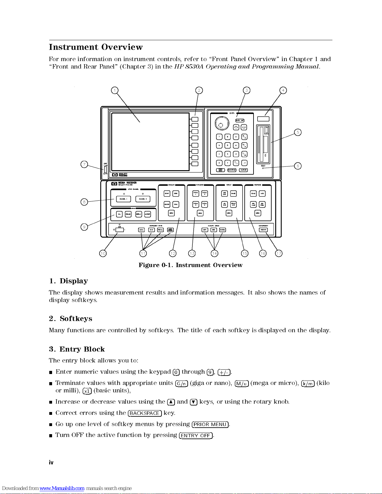
Instrument Overview
For more information on instrument controls, refer to \Front Panel Overview" in Chapter 1 and
\Front and Rear Panel" (Chapter 3) in the
HP 8530A Operating and Programming Manual
.
Instrument
results
pressing
by
0-1.
and
485
5
key.
pressing
information
4
5
through
0
4
5
(giga or nano),
G/n
and
495
4
PRIOR
4
ENTRY
Figure
Display
1.
display
The
display
2. Softkeys
Many functions are controlled by softkeys. The title of each softkey is displayed on the display.
Entry
3.
The entry
Enter numeric values using
Terminate values with appropriate units
or milli),
Increase or decrease values using the
Correct errors using the
up
Go
Turn
shows
softkeys
Block
block allows you to:
4
x1
one
the
OFF
measurement
.
5
(basic units),
softkey
of
level
active
4
BACKSPACE
menus by
function
the keypad
Overview
messages.
4
5,4
MENU
.
5
+/-
5
.
5
9
keys, or using the rotary knob.
OFF
It also
.
4
5
M/u
shows the
(mega or micro),
names of
4
5
(kilo
k/m
iv
Page 5
4. Status Display
This diagnostic/status display has the characters R L T S 8 4 2 1 in it. This display shows the
HP-IB Remote (R), Listen (L), or Talk (T) status, or shows if a service request \SRQ" has been
asserted (S). The numbers are self-test indicators.
5. Disc Drive
The disc drive accepts 3.5 inch DOS or Hewlett-Packard LIF format disks. Either 720 kB or
1.44 MB DOS disks can be used. The HP 8530A can show disc contents, format in DOS or LIF
format, delete les, or undelete the last le deleted (undelete works on LIF format discs only).
6. TEST Button
Causes self tests to be performed on the receiver.
7. AC power switch
This switch applies AC power to the Display section (turn this ON after the power switch on
10).
item
see
the
bottom
box,
Channel
8.
two
The
Menus
4
5
CAL
4
DOMAIN
4
DISPLAY
4
MARKER
switch
data
controls
parallel
features
displayed
9.
Contains
10. AC power switch
This
Select
the
channels
independently
separately
several
selects
5
5
selects how many dierent measurements to display on the screen at once.
5
allows you to use the marker features of the instrument.
make
processing
major
three
Angle
applies
of
or
,
functions
dierent
power
C
A
pathways
they
,
measurement,
same
.
other
the
be
can
types
Frequency
to the
channel
Each
channel.
overlaid
measurement
of
Time
or
,
bottom
and
allows
nal
The
the
on
Domain
section.
split
then
you
results
graticule
same
calibration.
operation.
to
the
apply
from
raw
dierent
each
.
data
channel
results into
instrument
be
can
two
v
Page 6
11. Instrument State
Contains several functions:
4
5
LOCAL
connected to the System Interconnect. (The System Interconnect is the HP 8530A's
\personal" HP-IB bus. Any devices connected to it (printers, plotters, RF or LO sources) are
controlled exclusively by the HP 8530A.
4
SAVE
registers (for later recall).
allows you to specify the HP-IB addresses of the receiver and \slave" instrument
5
and
4
RECALL
5
allow you to save current measurement settings to one of eight save/recall
4
USER PRESET
time you turn power ON or press
12. Stimulus Block
The stimulus block controls most of the functions associated with the basic measurement setup.
Stimulus controls include:
Measurement start/stop or center/span values for angle, frequency,ortime.
ower
P
Sweep
Number
Domain).
Frequency
Trigger
85370A
HP
arameter Block
P
13.
block
This
4
P
signal
very
to
signals
ARAM
are
accurate
measure
4
on
5
levels
(single
type
measurement
of
List
mode
P
selects
select
5
measured,
measurement
any
a1,
the
any setup you save in save register 8 becomes the \user preset" state. Any
RF
for
sweep
mode
(internal,
osition
which
dierent
and
the
of
b1,
a2,
LO
and
continuous
,
points
setup
external,
Encoder
8530A
HP
\ratioed"
then
results
input
four
b2
or
4
USER PRESET
sources
(in
.
or
controls
inputs
measurements
mathematically
are
Softkey
.
lines
input
.
sweeps
Frequency
HP-IB).
.
without
.)
lines
5
the settings stored in register 8 are retrieved.
ramp sweep
,
Domain),
measure
to
.
menus
ratioing. (This
the
.
\Ratio"
divided
under
sweep,
,step
increment angle
or
that
This
.
4
main keys
means
together
block's
this
feature allows
and more).
(in Angle
through
5
1
ARAM
P
and reference
test
a
method provides
4
MENU
key
5
you to
allows
check the
you
14. Auxiliary Menu
This area contains three control keys:
print
to
4
COPY
4
DISC
disc-related
4
SYSTEM
are controlled are: phase lock, IF calibration,
(used when more than one source is connected to
service menus that are used when troubleshooting the instrument.
15. Format Block
This block
log format.
vi
allows
5
allows
5
you
the
use
to
you
you
to
.
select
functions
5
contains instrument conguration functions
allows
plot
or
disc
dierent
measurement results
the
drive
to save
display
or
power leveling, and multiple-source setup
formats
.
format
,
les
load
Examples of the type of functions that
.
the HP 8530A). The system key also has
as
such
discs
Cartesian
or
polar
perform
and
,
other
linear
in
,
or
Page 7
16. Response Block
This block controls the following:
Display scale
Position and value of the reference line
Automatic display scale (autoscale)
Measurement averaging
Trace smoothing
Trace \normalization" (A specic point on the measurement trace is set to 0 dB, and other
portions of the trace are displayed relative to that.)
Magnitude slope and oset control
Phase oset control
Coaxial, waveguide, or user-denable electrical delay selection
17.
4
RESTART
5
This
progress
in
key
is
used
If
.
when
you
are
you
using
are
making
the
single
swept
sweep
measurements
4
,
mode
REST
ART
.
It
5
can
aborts
start
measurement
any
new
a
sweep
that is
.
vii
Page 8
Guide to this Manual
8530A
HP
the
with
the
of
Examples
in
front
of
.
HP
the
panel
the HP
8530A,
Figure
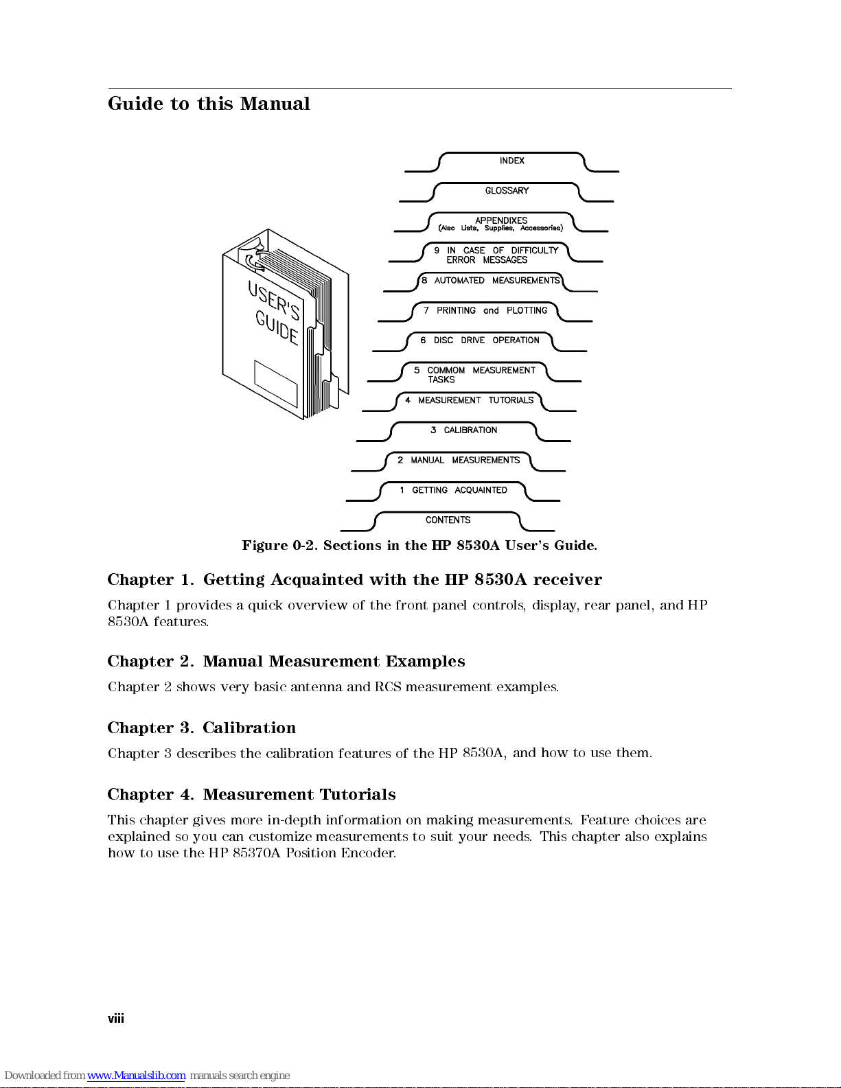
Getting
Chapter
Chapter
8530A
Chapter
Chapter 2 shows very basic antenna and RCS measurement examples.
Chapter 3. Calibration
Chapter
Chapter 4. Measurement Tutorials
This chapter gives more in-depth information on making measurements
explained
how to use
1.
quick
provides
1
features
2.
describes
3
so you can customize measurements to suit your needs
the HP 85370A P
a
.
Manual Measurement
the
0-2. Sections
cquainted
A
overview
calibration
osition Encoder
features
User's
8530A
controls
Guide
receiver
display
,
how
and
. This chapter also explains
.
panel,
rear
,
them.
use
to
eature choices are
.F
and
HP
viii
Page 9
Chapter 5. Common Measurement Tasks
Chapter 5 describes specic measurement tasks such as:
Finding boresight Using Markers
Determining 3 dB beamwidth Measuring depth of a null
Displaying data relative to the peak Displaying more than one trace
Using averaging Using frequency list mode
Chapter 6. Disc Drive Operation
Explains how to use the built-in disc drive to store and retrieve data, instrument state les,and
other types of information.
Chapter 7. Printing and Plotting
Describes how to output screen \snapshots" or tabular data to printer or plotter. A wide range
of HP printers and plotters are covered in detail.
utomated
Making
Chapter
Chapter
how
receiver
point.)
Chapter
This
How
What
How
Appendix
Conguring the system for optimum dynamic range entails using the highest RF power settings
possible without overdriving the receiver. Appendix A explains how to congure your system
so optimum dynamic range is available.
Appendix
Lists
plotters, and monitors
8.
explains
8
the
use
to
automatically
to
9.
to
to
to
explains:
solve
do
solve
A,
B
chapter
compatible
ast
F
Case
In
common
when
basic
Optimizing
Compatible
,
RF
A
measure
to
how
Multiplexing.
IF
switch
of
operation
specic
hardware
LO
and
.
between
Diculty
error
problems
Dynamic
Instruments
sources,
Measurements
5,000 points
up to
IF
ast
(F
dierent
problems
messages
frequency
are
.
Range
per second
multiplexing
input
displayed
and P
converters
eripherals
similar
is
ratios
the
on
positioner
,
using F
each
at
screen.
ast
ast CW
F
to
angle
controllers
mode
CW
,but
frequency
or
printers
,
and
,
allows
the
,
Appendix C, Supplies
Lists commonly-needed supplies (plotter pens
domain option, rack-mount hardware, connector savers, and touch-up paint).
Connector
,
Appendix
Explains
D
connector
care
techniques
ccessories, After-Sale Options
,A
, discs) and after-purchase options (time
procedures
.
Care
and
, paper
cleaning
ix
Page 10
Other Manuals that Come with the HP 8530A
The following manuals are supplied with the HP 8530A:
Operating and Programming Manual
The Operating and Programming manual serves two purposes:
It provides in-depth reference information on front panel features, organized around the
front panel functional blocks.
It provides tutorial information on remote programming, with many HP BASIC examples.
Keyword Dictionary
The Keyword Dictionary explains:
The function of each front panel key or display softkey, organized by key/softkey name.
What each HP-IB programming code does, including syntax and programming sequence
details.
panel
Front
alphabetical
On-Site
The
Installation
Troubleshooting
Performance
Typeface
Bold
Italics
Computer
Display
4
Front P
NNNNNNNNNNNNNNNNNNNNNNNN
NNNNN
Soft Keys
Service
On-Site
anel Keys
key/softkey
.
order
Service
tests
Conventions
5
and
Manual
Manual
specications
and
Bold type is used for terms that are listed in the glossary.
Italic type is used for emphasis and for the titles of manuals and other
publications. It is also used when describing a computer
Computer
Display
receiver's
Front panel keys are enclosed in
Soft keys are the keys on the right-hand side of the display
function of
programming
contains:
type
is
type
display
these keys changes depending on the menu you are in.
code
used
is
used to
.
descriptions
depict
to
messages
show
coexist
HP-IB
boxes.
the
in
commands
which
are
section,
same
variable
.
displayed
the
on
.The
in
.
x
Page 11
Getting Acquainted with the HP 8530A Receiver
Chapter Contents
Product Description
Receiver Performance
Measurement Features
Input/Output Features
Principles of Operation
Front Panel Overview
1
Getting
Acquainted with
the
HP
8530A
Receiver
1-1
Page 12
Product Description
The HP 8530A is a high-performance receiver that has been designed specically for antenna
and radar cross section (RCS) measurements.
The HP 8530A allows you to make angle-scan and frequency-scan measurements of antennas,
or make RCS measurements using the time domain feature.
Very fast measurement speeds are possible with the HP 8530A. By using a computer controller,
the receiver can measure up to 5,000 data points per second.
The receiver has very high sensitivity and dynamic range. The HP 8530A provides a large
amount of measurement exibility, providing the features you need for many dierent types of
measurements.
The HP 8530A must be used with a frequency down converter. The following HP down
converters are supported:
HP 8511A/B frequency converter
HP 85310A distributed frequency converter
HP 85325 millimeter wave subsystems (the HP 85325A and HP 85309A, used together, make
a complete frequency converter system).
reference
and
test
MHz
the
to 20
basic
block
diagram
of
an
products down-convert
These
signals
antenna
that are
measurement
measured by
system.
microwave (or
the HP
8530A. Figure
millimeter) signals
shows
1-1
the
Getting Acquainted
1-2
with
HP
8530A
Receiver
Page 13

Basic
over a
1-1.
wide
capability
Figure
Receiver Performance
The most important feature of the HP 8530A is the accuracy and speed with which it makes
measurements. The important performance features are:
Excellent sensitivity.
speed
linearity
data acquisition
Excellent
High
Sensitivity
Antenna
dynamic
.
Measurement
.
range
Block
Diagram
The foundation of good system performance
measure very small signals
noise. When used with the HP 85310A frequency
of0113 dBm from 3 to 18 GHz, and096 dBm from 18 to 26.5 GHz. Excellent sensitivity
improves the signal-to-noise ratio of your system, allowing you to measure smaller signals more
greater
with
and
quickly
,
. Excellent sensitivity
accuracy
and high speed is sensitivity|the ability to
is only possible in systems that have very low
converter, the HP 8530 can measure signals
.
Getting
Acquainted with
the
HP
8530A
Receiver
1-3
Page 14
Linearity over a Wide Dynamic Range
Accuracy errors can occur when the power from the test antenna varies in signal level. For
example, assume that a test antenna has a bore-sight measurement of 0 dBi (020 dBm) and an
o-axis null of050 dBi (070 dBm). This is a dierence of 50 dB. The HP 8530A receiver has
0.03 dB of error in this case. Even with a 60 dB dierence the HP 8530A has less than 0.04 dB
of error due to linearity. This specication is called \dynamic accuracy."
Fast Measurement Speed
The HP 8530 can measure 5000 points per second. As mentioned earlier, averaging slows
measurement speed. Because of the HP 8530A's excellent performance, you will need less
averaging, and can make faster measurements, than you would when using a receiver with less
performance.
High speed measurements are performed using the \Fast CW" mode, and must be done through
computer control.
the
Getting Acquainted
1-4
with
HP
8530A
Receiver
Page 15
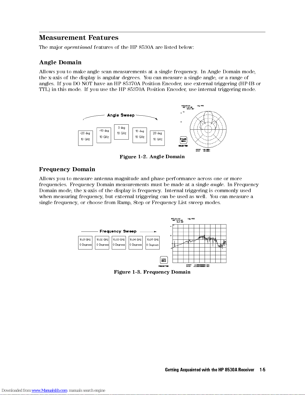
Measurement Features
The major
Angle Domain
Allows you to make angle scan measurements at a single frequency. In Angle Domain mode,
the x-axis of the display is angular degrees.You can measure a single angle, or a range of
angles. If you DO NOT have an HP 85370A Position Encoder, use external triggering (HP-IB or
TTL) in this mode. If you use the HP 85370A Position Encoder, use internal triggering mode.
Frequency
Allows
frequencies
Domain
when
single
operational
Domain
measure antenna
to
you
Frequency
.
,
mode
measuring
frequency
x-axis
the
frequency
choose
or
,
features of the HP 8530A are listed below:
Domain
phase
must be
performance
Internal
.
be
can
Frequency
made
used
List
at
triggering
as
sweep
Domain
of the
but
,
from Ramp
Angle
Figure
magnitude and
measurements
display
external triggering
1-2.
frequency
is
Step
,
or
single
a
well.
across
modes
or
one
.
angle
commonly
is
can
ou
Y
.
more
Frequency
In
used
measure
a
Figure
1-3.
Frequency
Getting
Domain
Acquainted with
the
HP
8530A
Receiver
1-5
Page 16
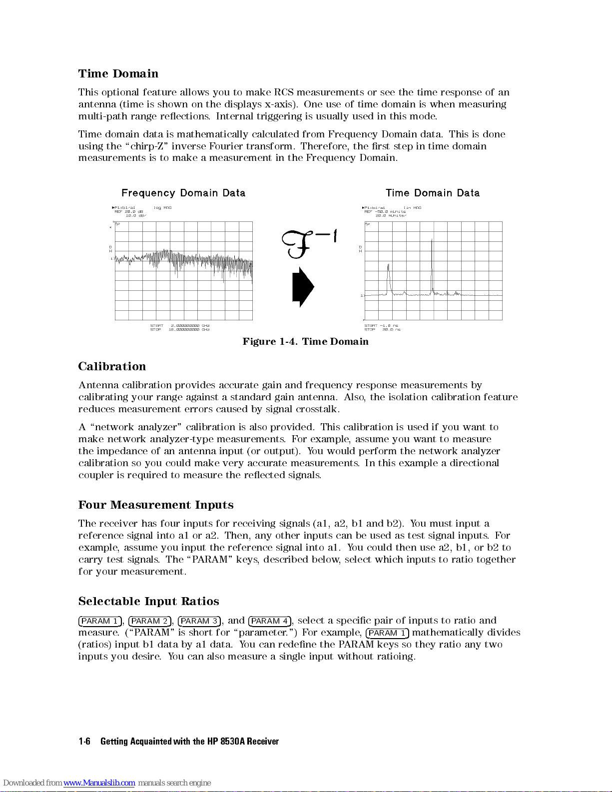
Time Domain
This optional feature allows you to make RCS measurements or see the time response of an
antenna (time is shown on the displays x-axis). One use of time domain is when measuring
multi-path range reections. Internal triggering is usually used in this mode.
Time domain data is mathematically calculated from Frequency Domain data. This is done
using the \chirp-Z" inverse Fourier transform. Therefore, the rst step in time domain
measurements is to make a measurement in the Frequency Domain.
Domain
Time
Figure
1-4.
Calibration
measurements
isolation
is used
example a
then
which
inputs to
5
calibration
if you
want to
network
use a2,
mathematically
Also
calibration
,
ou
Y
a1.
select
,
response
the
,
assume you
perform the
In this
could
,
4
PARAM 1
frequency
and
by
also
is
(or
accurate
reected
,
keys
4
PARAM 4
gain
antenna.
gain
crosstalk.
signal
provided.
.
output).
measurements.
signals.
signal
described
5
.") F
This
example
or
F
ou would
Y
into
below
, select a specic pair of inputs to ratio and
or example
Antenna
calibrating
reduces
\network
A
make
the
calibration
coupler
Four Measurement Inputs
The receiver has four inputs for receiving signals (a1, a2, b1 and b2). You must input a
reference signal into a1 or a2. Then, any other inputs can be used as test signal inputs.For
example
carry
for
Selectable Input Ratios
4
PARAM 1
measure.
(ratios) input b1 data by a1 data. You can redene the PARAM keys so they ratio any two
inputs you desire.You can also measure a single input without ratioing.
calibration provides
antenna
an
could
to
The
,
4
5
measure
input
PARAM 3
against
calibration
\P
your range
measurement errors
analyzer"
network
impedance
is
,
test
your
5
analyzer-type
of
you
so
required
assume you
signals.
measurement.
,
4
PARAM 2
(\PARAM" is short for \parameter
accurate
a
caused
measurements
input
very
make
the
reference
the
ARAM"
, and
5
standard
by
feature
to
want
measure
analyzer
directional
b2
or
b1,
together
ratio
divides
to
the
Getting Acquainted
1-6
with
HP
8530A
Receiver
Page 17
Flexible Triggering
The HP 8530A provides three ways of triggering measurements:
Internal When in Internal trigger mode, the receiver does not require any
external or HP-IB triggering. This is useful when making frequency
measurements, or when using the HP 85370A Position Encoder.
External Triggering Allows you to trigger measurements using a TTL increment signal
produced by a positioner controller. This allows the receiver to take data
when the positioner is aligned with each measurement angle.
HP-IB Triggering Allows a computer to trigger a measurement by issuing a GET command
over the HP-IB bus.
Save/Recall Registers
The receiver has eight Save/Recall registers. Each can save current measurement settings for
instant recall at a later time. Register 8 is the \User Preset" register. Settings saved under
register 8 become active whenever you turn the receiver ON, or when you press
4
USER PRESET
5
.
erformance
Measure
Normalize
The
amplitude)
reference
be
will
Remote
HP
The
HP-IB
modes
Data
HP
The
Antenna patterns
Frequency response measurements
Time domain
Radar Cross Section (RCS) frequency and time domain measurements
HP
The
Display F
You can select logarithmic or linear
display format (Cartesian only). Y
the screen.
P
Trace
.
dB
0
to
point.
relative
Programming
8530A
All
.
operation
of
Presentation
8530A
8530A
When
the
to
can be
front panel
can
allows
ormats
function
ou
Y
peak.
and current
show measurement
you
Relative
sets
then
can
is
data
controlled
features
Features
print
to
use
saved,
remotely
are
instrument or
ou can display
to
(the
lobe
main
the
of
peak
the
magnitude
trace
view
markers
printed,
supported.
results right
plot measurement
or
magnitude display formats (Cartesian or polar), or phase
to
output
or
computer
query
can
status
display
on its
results
one,two, or four parameters simultaneously on
from
plotted,
any
ou
Y
system
to
that
the
.
.
.
Main
the
of
eak
P
the
Lobe
point
data
values
computer
communicate
can
analyzer
can
It
of
relative
magnitude
,
determine
to
display:
highest
to this
values
using
current
Multiple Measurements Can be Shown Simultaneously
The HP 8530A allows you to view up to four parameters at once, in split or overlay
presentation.
measurement
Alternatively
channels
,
(more
you
on
display
can
channels
one
explained
is
parameter from
later).
Getting
Acquainted with
each
of
independent
the
HP
the
8530A
Receiver
1-7
Page 18
Trace Memory and Trace Math
The trace memory feature is similar to the storage feature in a storage oscilloscope.You can
store the current data trace to memory, then compare it to subsequent measurement traces.
Trace math features allow you to perform vector addition, subtraction, multiplication, and
division. These operations are performed using the current data trace and the memory trace.
Each parameter has independent trace memory/math operation. In addition, trace math in
Channel 1 is independent from trace math in Channel 2.
Markers Display Precise Values for Any Point on display Traces
Five measurement markers give detailed information about any point on the measurement
trace. Delta markers allow you to show the dierence in amplitude, phase, angle,ortime
between any two points on the screen.
External Video Monitor
The HP 8530A can display results on an external multisync monitor. Refer to Appendix B for
details.
Optional Network Analysis
Option
This
frequency
accuracy
011
allows
adds
you
or
in
high-performance
measure
to
optional
arameter
S-P
time
the
domains
network
vector
transmission
.
measurements
network
These
analysis
reection
and
advanced
.
features
properties
calibration
(HP
of
features
8510C
microwave
operation).
provide
devices
optimum
in
the
Getting Acquainted
1-8
with
HP
8530A
Receiver
Page 19
Input/Output Features
The HP 8530A can control other instruments, and has many input/output capabilities using
HP-IB, System Bus, RS-232, external monitor interface, and TTL BNCs.
Printing and Plotting Features
The HP 8530A can output data to a wide range of HP-IB or RS-232 printers or plotters. Laser
printers are also supported.
Many Supported Peripherals
The HP 8530A can control RF and LO signal sources, frequency converters, and large external
display monitors. Refer to Appendix B for details.
Built In Disc Drive
The built in disc drive allows you to save measurement data, data from memory, instrument
conguration setups, save/recall registers, calibration data, or user-created graphics. Both
LIF
and
DOS
format
DOS
format
LIF
workstation
formats
disc
compatible
is
compatible
is
family
supported,
are
MS-DOS
with
Hewlett-P
with
.
and
R
based
ackard
computers
computers
,
,
such
such
as
as
IBM
the
PCs
HP
automatically
are
types
disc
both
recognized.
compatibles
and
9000 Series
300
.
Getting
Acquainted with
the
HP
8530A
Receiver
1-9
Page 20
Principles of Operation
This information is provided so you can have a better understanding of how the HP 8530A
makes measurements. If desired, you can skip this section and come back to it when
convenient.
Description of the HP 8530A
A simplied block diagram of the HP 8530A receiver is shown in Figure 1-5. It is a high
performance vector receiver with four inputs, two independent digital processing channels,and
an internal microcomputer that controls measurement, digital processing, and input/output
operations. Examples of \digital processing" are features such as averaging, time domain,
calibration, and so on. A special System Bus gives the receiver complete control over the
RF source and, if required, LO source. This interface allows the receiver to make hard copy
outputs to HP-IB compatible printers or plotters. Two RS-232 ports are also supplied for
printing or plotting.
The system must contain a frequency converter, which down converts the RF measurement
frequencies to a 20 MHz IF. The HP 8530A requires this frequency for its inputs.To create
the IF frequency, the HP 8511A/B frequency converter uses a built-in local oscillator. The
est
\T
the
over
is
built-in
Set
measurement
MHz
supply
the
LO
Interconnect"
signal.
IF
LO
an
System
Bus
digitally
that
signals
Other
signal.
.
tuned
links
with
down
The
the
by
HP
the
similar
a
converters
8530A
HP
8530A. This
HP
such
,
and
external
8530A
frequency
tunes
that
as
digital tuning
the HP
oset by
is
HP 85310A,
the
LO
data is
8511A/B.
sources with
The local
20 MHz.
require another
sent
oscillator mixes
The result
HP-IB commands
is the
source
to
sent
the
20
over
the
Getting Acquainted
1-10
with
HP
8530A
Receiver
Page 21
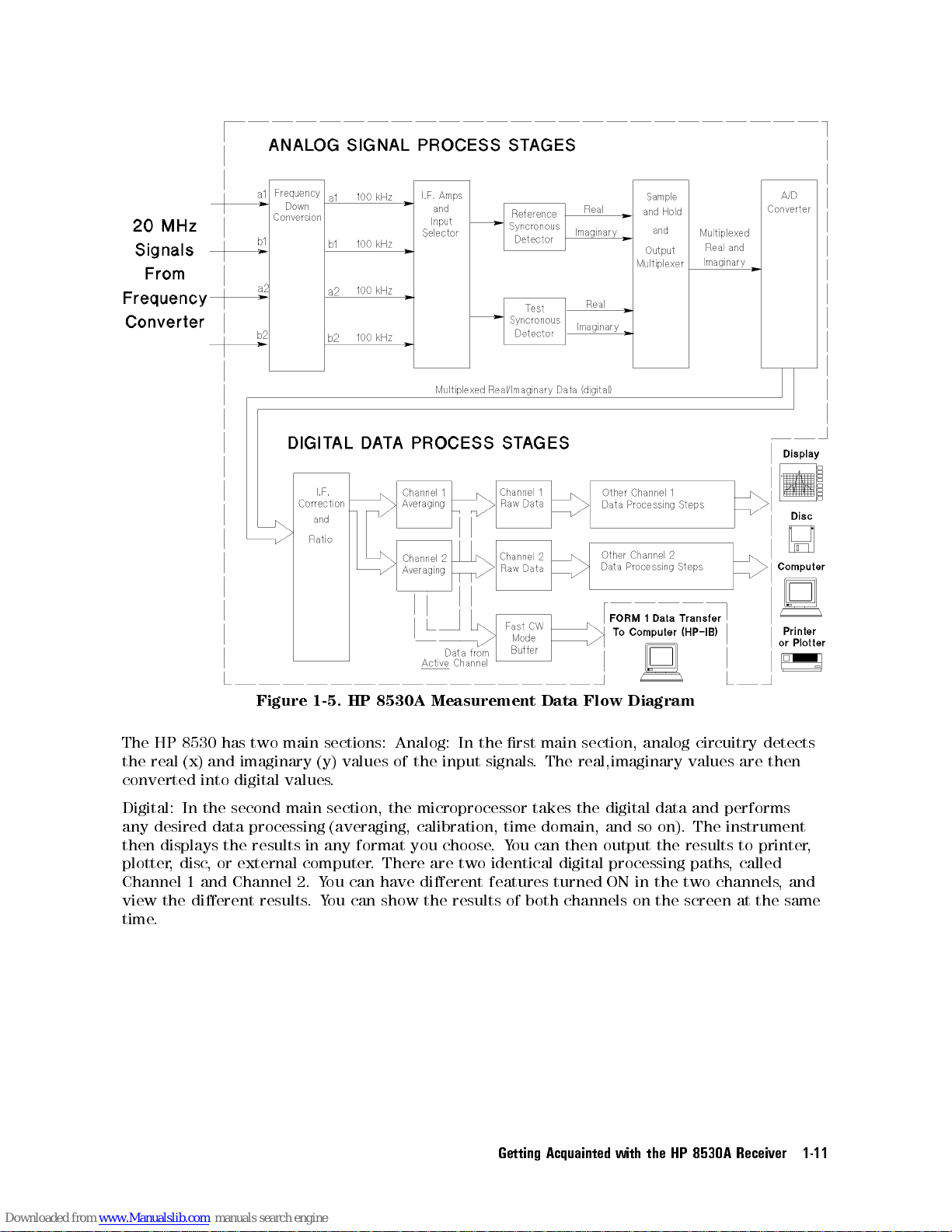
Figure
1-5.
HP
8530A
Measurement
Data
Flow
Diagram
In
choose
two
are
dierent
can
ou
Y
.
identical
features
Getting
then
digital
turned
Acquainted with
can
There
.
have
Analog:
you
sections:
main
two
has
8530
HP
The
the real (x) and imaginary (y) values of the input signals. The real,imaginary values are then
converted into digital values.
Digital: In the second main section, the microprocessor takes the digital data and performs
any desired data processing (averaging, calibration, time domain, and so on). The instrument
any format
results
disc
,
and
or
the
external
Channel
displays
then
plotter,
Channel 1
view the dierent results
time.
in
computer
ou
Y
2.
ou can show the results of both channels on the screen at the same
.Y
main section,
rst
the
analog circuitry
results
output
processing paths
ON
the
in the
the
HP
two
8530A
detects
to printer
called
,
channels
Receiver
,
and
,
1-11
Page 22
Analog Signal Process Stages
During a typical Frequency Domain measurement, the test signal source is swept from a lower
to a higher frequency.
During a typical Angle Domain measurement, a single frequency can be measured while the
antenna-under-test is moved around one axis.
Initially, the HP 8530A receives up to four 20 MHz signals from the external frequency
converter. The receiver separately down converts each signal to a 100 kHz IF carrier frequency
that can be used by the detection circuitry. Because frequency conversions are phase coherent,
and the IF signal paths are carefully matched, magnitude and phase relationships between
the input signals are maintained throughout the frequency conversion and detection stages.
Automatic, fully-calibrated autoranging IF gain stages maintain the IF signal at optimum levels
for detection over a wide dynamic range.
Each measurement channel can use input a1 or a2 as the reference signal. The selected input
is also used as the phase-lock reference.
Note
Any
of
the
In hardware gating applications, the pulsed reference signal may not be suitable
for phase locking. In this case, you can use the other reference input for phase
you
a1,
input
on
press
,
is
RESPONSE
three
locking. F
the phase
a2 as
NN
N
N
N
N
REDEFINE
remaining
N
N
N
N
N
N
N
N
N
NN
NN
NN
example
or
lock
N
N
N
N
NN
NN
NN
NN
N
N
N
N
N
N
N
N
PARAMETERS
inputs
N
N
N
N
N
N
N
N
N
N
can
assume
,
reference
N
NN
NN
N
N
N
N
be
NN
NN
NN
N
N
N
PHASE
used
N
N
NN
your
.
N
N
N
N
as
pulsed
accomplish
o
T
N
NN
N
N
N
N
N
N
N
N
N
N
N
LOCK
test
reference
NN
NN
N
N
N
N
.
a2
inputs
this
.
4
MENU
can
use
5
one
input
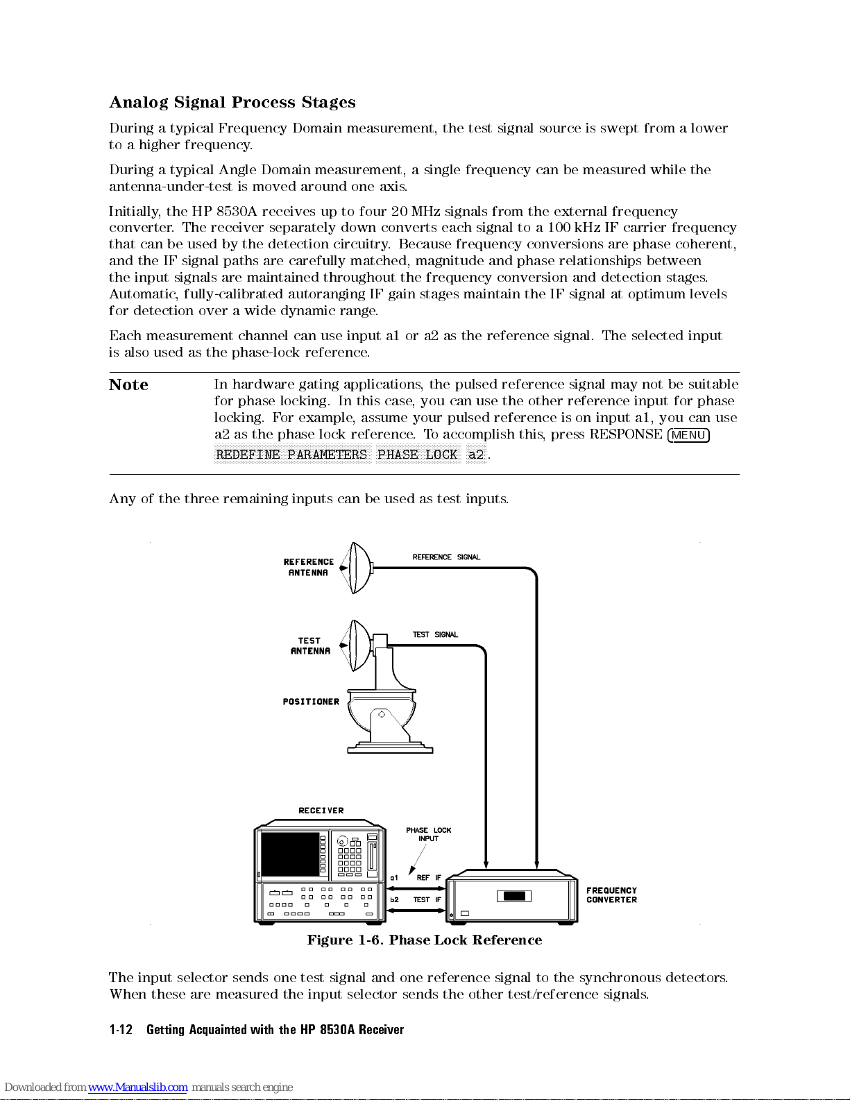
The
these
When
Getting Acquainted
1-12
selector
are
sends
measured
with
the
the
Figure
test
input
8530A
HP
signal
selector
1-6.
and
Receiver
Phase
reference
one
sends the
Lock
Reference
signal
test/reference
other
to
synchronous
the
signals
detectors
.
.
Page 23
The synchronous detectors develop the real (x) and imaginary (y) parts of the test or
reference signal by comparing the input to an internally-generated 100 kHz sine wave. This
method practically eliminates drift, osets, and circularity errors as sources of measurement
uncertainty. Each x,y pair is sequentially converted to digital values which are sent to the
main microprocessor.
Digital Data Process Stages
Digital signal processing proceeds under the control of the receiver's rmware operating system
executed by the main microprocessor.
About the Main Microprocessor
The main microprocessor is a 32-bit Motorola 68020 microprocessor running at a clock speed of
16 MHz. The rmware operating system takes advantage of multi-tasking software architecture
and several distributed processors to provide very fast data acquisition and display update
speed.
Raw Data Stages
The microprocessor accepts the digitized real and imaginary data, and corrects IF gain and
quadrature
correction
IF
the
in
automatic
by
way
any
errors
feature
the
before
is
user
any
are
stage
dierent
.
data
other
calculated
the
from
processing
periodically with
calibration
user
is done
. The
an automatic
features
,and
calibration coecients
self-calibration. This
cannot be
controlled
used
in
independent
to
sent
are
data
the
orm
F
These
.
in
1
is
of
Channel
or
channel
raw
1
.
one
holds
described
if
format.
1
features
Channel
data
you
Time
2,
If
2.
ast CW
F
If
.
array
data
X,Y
the
in
using
are
are
Domain,
and select
F
the
Similarly
.
pair
8530A
HP
the
\Other
the
mode
CW
ast
is
mode
Channel
,
special
a
in
eyword
K
CW
ast
F
Data
display
Frequency
format,
utomated
not
is
being
mode
identical
ratioed
inputs
the
Next,
Channel
Now
in
used,
averaged
Data
compressed data
Dictionary
The
Other Digital Processing Stages
Channel 1 and 2 data processing proceeds independently through subsequent data processing
steps. Dierent measurement features can be used in each channel, causing the measurement
results
Processing"
and
Domain
same device
More information on the \other"
Operation," later in this guide
1
selected
any
,
data
,
use
Channel
data
\arrays"
buer
be
to
on. F
so
in Channel 1. This allows you to make two dierent types of measurements on the
are
Channel
and
averaging
the
to
sent
is
averaged
1
is stored
are data
format called
ast CW
The F
.
contains up
processed
shown in
steps
example
or
, and display the results simultaneously
together
processing
data
2
is
CW
ast
F
data
in the
holding locations
to 100,000
and
,
Channel
buer can
shown
Figure
can
you
.
and
paths
performed
buer
stored
is
\Form
X,Y data
in dierent
1-5
select
data processing steps is provided in \Standard A
on
from
in
raw
2
A
.
1." This
data
send
and
,
Time
the
data
pairs
include
copies
.
Channel
active
the
Channel
array
data
array
format
computer
to
in
ways
Domain
.
calibration,
2
.
Getting
Acquainted with
the
HP
8530A
Receiver
1-13
Page 24
Front Panel Overview
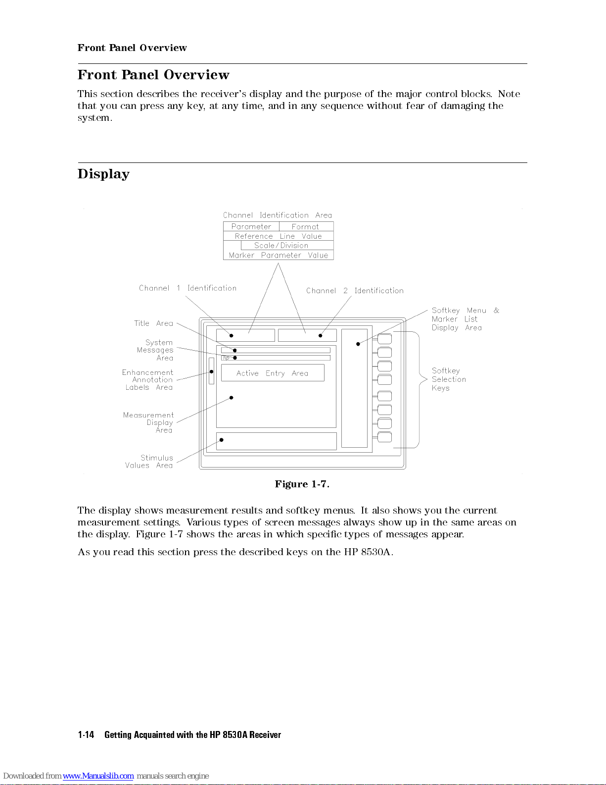
Front Panel Overview
This section describes the receiver's display and the purpose of the major control blocks. Note
that you can press any key, at any time, and in any sequence without fear of damaging the
system.
Display
Figure 1-7.
The display shows measurement results and softkey menus. It also shows you the current
measurement settings.Various types of screen messages always show up in the same areas on
the display. Figure 1-7 shows the areas in which specic types of messages appear.
8530A.
HP
the
read
you
As
Getting Acquainted
1-14
this
section
with
press
the
described keys
the
8530A
HP
Receiver
on
Page 25
Front Panel Overview
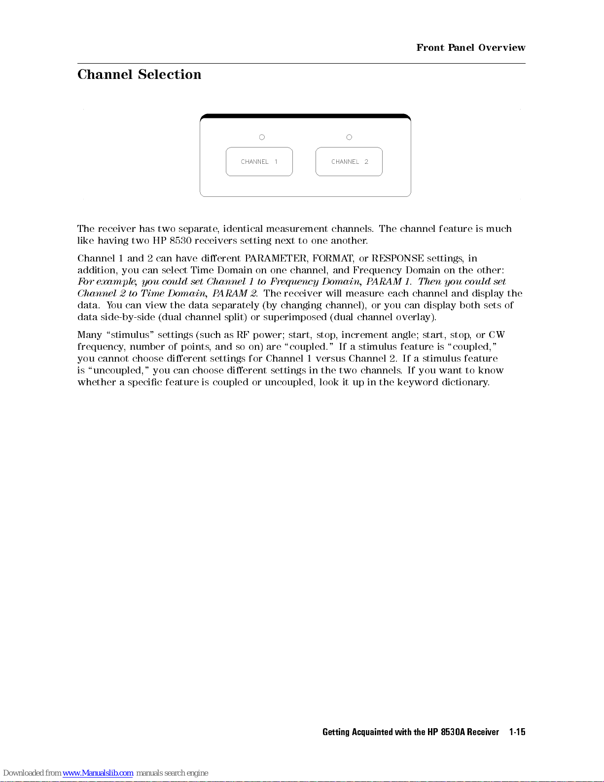
Channel Selection
The receiver has two separate, identical measurement channels. The channel feature is much
like having two HP 8530 receivers setting next to one another.
Channel 1 and 2 can have dierent PARAMETER, FORMAT, or RESPONSE settings,in
addition, you can select Time Domain on one channel, and Frequency Domain on the other:
For example, you could set Channel 1 to Frequency Domain, PARAM 1. Then you could set
display
display
and
both
sets
Time
to
Channel
data. Y
data side-by-side
2
ou can
view the
Domain,
(dual channel
P
data separately
ARAM
split) or
receiver
The
2.
changing
(by
superimposed (dual
measure
will
channel),
channel
or
each
can
you
overlay).
channel
the
of
\stimulus"
Many
frequency
cannot
you
\uncoupled,"
is
whether
a
number
,
choose
specic
settings (such
points
of
dierent
choose
can
you
feature
is
as RF
and
,
settings
dierent
coupled
so
power;
are
on)
Channel
for
settings
uncoupled,
or
,
stop
start,
\coupled." If
versus
1
the
in
look
increment
a stimulus
Channel
channels
two
in
up
it
angle;
2.
the keyword
start,
feature
a stimulus
If
If you
.
,
stop
\coupled,"
is
feature
to
want
dictionary
CW
or
know
.
Getting
Acquainted with
the
HP
8530A
Receiver
1-15
Page 26
Front Panel Overview
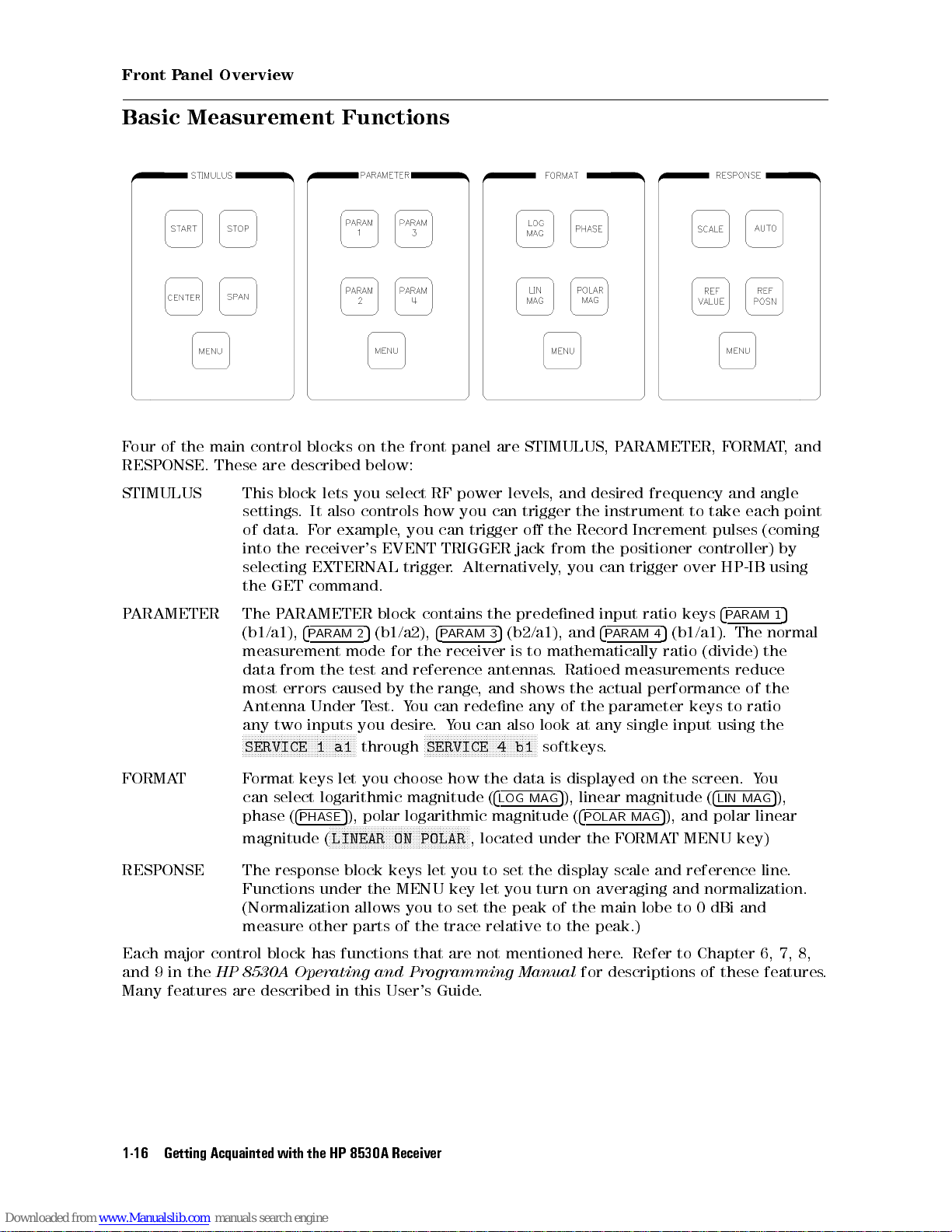
Basic Measurement Functions
Four of the main control blocks on the front panel are STIMULUS, PARAMETER, FORMAT,and
RESPONSE.
STIMULUS This
These
settings
of
into
selecting
the
described
are
block
data.
the
GET
It
.
or
F
receiver's
EXTERNAL
command.
below:
you
lets
controls how
also
example,
select
you can
EVENT
trigger
power
RF
you can
TRIGGER jack
.
levels
trigger
Alternatively
,
trigger
the
o
from the
,
desired
and
the
Record
you can
frequency
instrument
Increment
positioner
trigger
and
take
to
pulses
controller)
HP-IB
over
angle
each
(coming
using
point
by
predened
contains
ARAMETER
P
ARAMETER
P
FORMAT Format keys let you choose how the data is displayed on the screen. You
RESPONSE
Each major control block has functions that are not mentioned here
and 9 in the
Many features are described in this User's Guide
The
(b1/a1),
measurement
data
most
Antenna
any
N
N
N
N
N
SERVICE
can select logarithmic magnitude (
phase (
magnitude (
The
Functions
(Normalization
measure other
HP 8530A Operating and Programming Manual
4
ARAM
P
the
from
errors
Under
two inputs
NN
NN
N
N
N
N
N
response block
N
N
NN
NN
4
PHASE
N
N
N
N
N
N
N
N
N
N
1
under
block
the
for
reference
the
ou
Y
desire
N
4
P
range
can
.
N
N
N
N
N
SERVICE
let
(b1/a2),
5
2
mode
and
test
caused
N
N
N
a1
NNNNNNNNNNNNNNNNNNNNNNNNNNNNNNNNNNNNNNNNNNNNNNN
LINEAR ON POLAR
by
est.
T
you
N
NN
N
N
through
5
), polar logarithmic magnitude (
keys
the MENU
allows you to set the peak of the main lobe to 0 dBi and
parts of the trace relative to the peak.)
the
(b2/a1),
5
3
ARAM
mathematically
to
receiver
ou
Y
NN
NN
N
N
N
N
you
key
is
shows
also
N
N
N
N
N
N
N
b1
.
any
look
N
NN
softkeys
the
turn
antennas
and
,
redene
can
N
N
N
N
N
N
N
N
N
N
NN
NN
4
4
LOG MAG
, located under the FORMAT MENU key)
set
to
you
let
.
input
4
and
ARAM
P
Ratioed
actual
the
parameter
the
of
any
at
.
5
), linear magnitude (
4
POLAR MAG
display
scale
averaging
on
. Refer to Chapter 6, 7, 8,
for descriptions of these features
(b1/a1).
5
4
ratio
measurements
performance
input
single
5
), and polar linear
and
and
ARAM
P
The
(divide)
reduce
of
ratio
to
keys
the
using
4
LIN MAG
reference
normalization.
the
line.
4
keys
ratio
5
1
normal
the
5
),
.
the
Getting Acquainted
1-16
with
HP
8530A
Receiver
Page 27
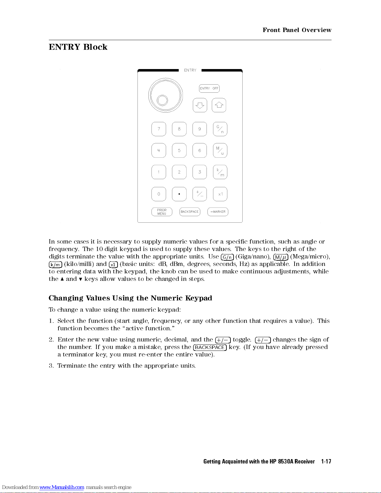
ENTRY Block
Front Panel Overview
specic
a
supply
degrees
in
K
the
entire
values
units
be
steps
eypad
and
supply
necessary
is
it
cases
some
In
digit
10
The
frequency
digits
4
k/m
entering
to
the
Changing
To change a value using the numeric keypad:
1. Select the function (start angle, frequency, or any other function that requires a value). This
function becomes the \active function."
Enter
2.
the
a
3. T
.
terminate
(kilo/milli)
5
data
keys
9
and
8
Values
new value
the
number
terminator
erminate the
.
value
the
4
and
x1
the
with
allow values
Using the
If you
key
make
, you
entry with the appropriate units
to
keypad
with
(basic
5
keypad, the
using
a
must
is
the
units:
to be
numeric
mistake
re-enter
numeric
to
used
appropriate
dBm,
,
dB
knob can
changed
Numeric
decimal,
,
press
,
the
these
.
used
.
the
4
CKSP
BA
value).
.
for
values
Use
seconds
,
to
4
+/
CE
A
.
4
G/n
make
5
0
key
5
function,
keys
The
(Giga/nano),
5
as
Hz)
,
continuous
4
.
toggle
(If you
.
+/
applicable
such
the
to
4
M/
adjustments
changes
5
0
already
have
the
of
right
(Mega/micro),
5
addition
In
.
,
sign of
the
pressed
while
or
angle
as
Getting
Acquainted with
the
HP
8530A
Receiver
1-17
Page 28
Front Panel Overview
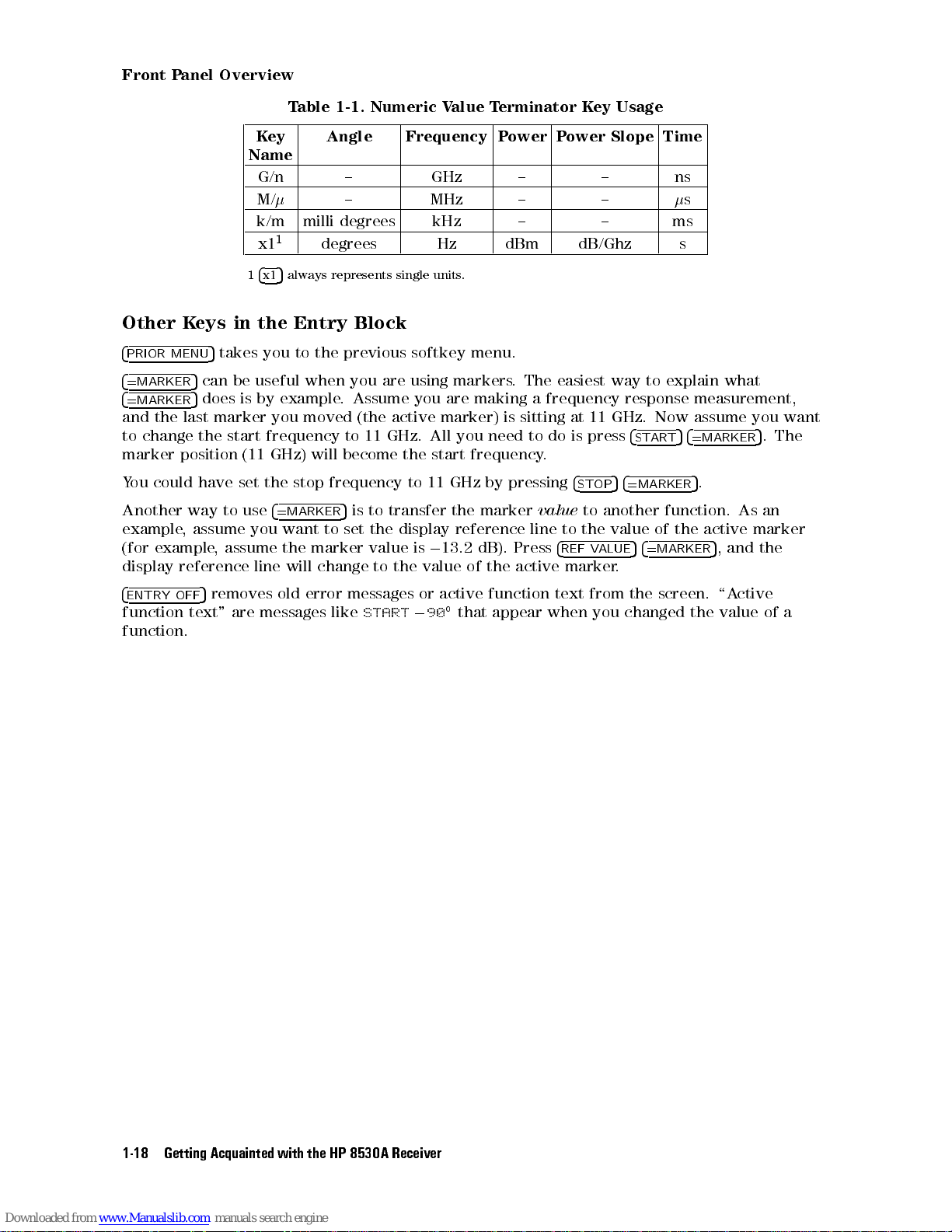
Table 1-1. Numeric Value Terminator Key Usage
Key
Name
G/n { GHz { { ns
M/
k/m milli degrees kHz { { ms
1
x1
1
4x15
Other Keys in the Entry Block
4
PRIOR MENU
4
=MARKER
4
=MARKER
and the last marker you moved (the active marker) is sitting at 11 GHz. Now assume you want
to change the start frequency to 11 GHz. All you need to do is press
marker position (11 GHz) will become the start frequency.
could
ou
Y
Another
example
example
(for
display
5
takes you to the previous softkey menu.
5
can be useful when you are using markers. The easiest way to explain what
5
does is by example. Assume you are making a frequency response measurement,
the
set
have
use
way to
assume
,
assume the
,
reference
4
=MARKER
you want
line
Angle Frequency Power Power Slope Time
{ MHz { {
degrees Hz dBm dB/Ghz s
always represents single units.
value
line
4
STOP
to another
the
to
4
V
REF
marker
ALUE
frequency
stop
5
to set
marker value
change
will
transfer the
is to
the
to the
11
to
display
0
is
value
GHz
marker
reference
dB).
13.2
of
pressing
by
the
Press
active
s
4
START54=MARKER
4
5
=MARKER
function.
the
of
value
4
5
=MARKER
.
.
5
active
5
,
As
and
5
.The
an
marker
the
4
ENTRY
function
function.
OFF
removes
5
text"
are
error
old
messages
messages
START
like
or
0
active
90
that
function
appear
text
when
from
you
screen.
the
changed
the
ctive
\A
value
of
a
the
Getting Acquainted
1-18
with
HP
8530A
Receiver
Page 29
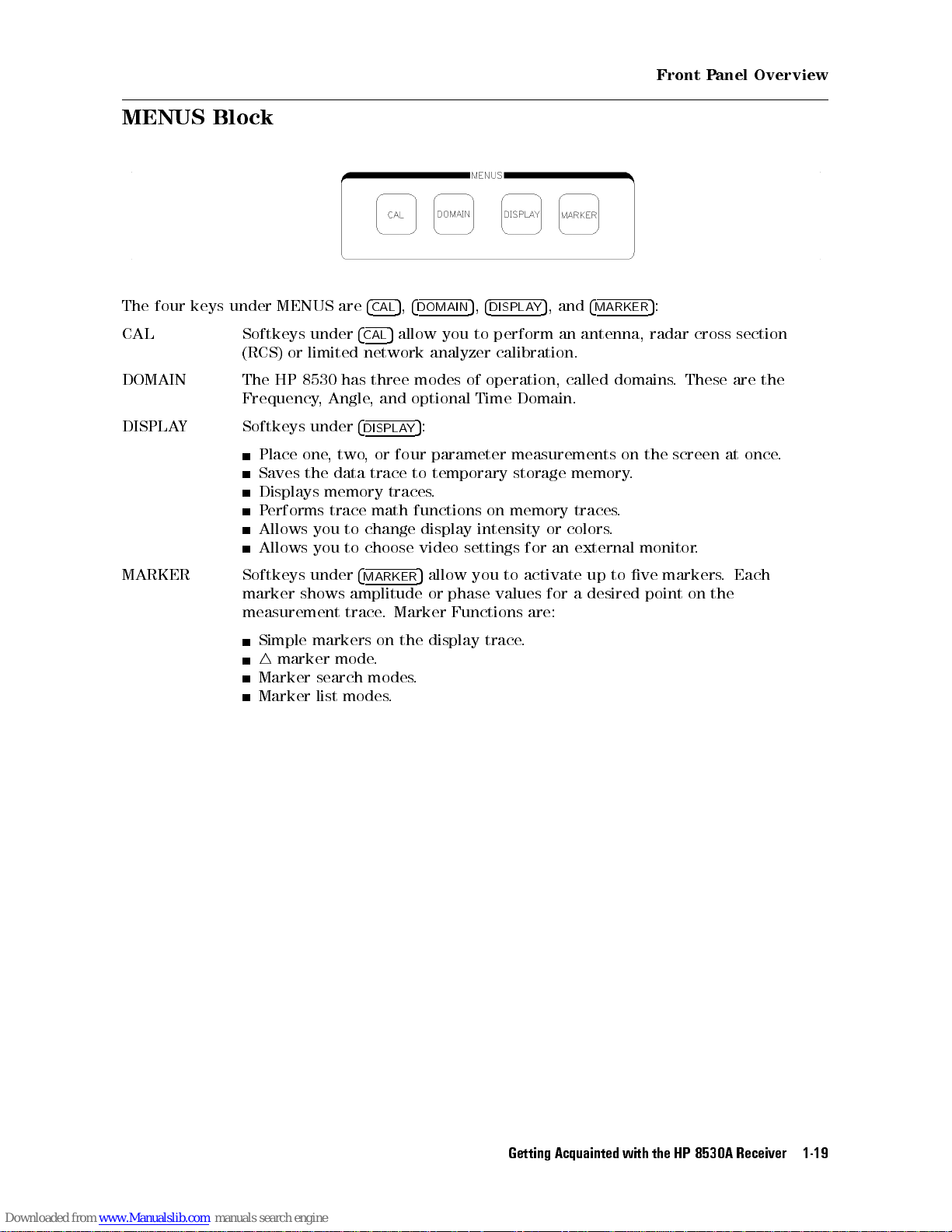
MENUS Block
Front Panel Overview
The four keys under MENUS are
CAL Softkeys under
(RCS) or limited network analyzer calibration.
DOMAIN The HP 8530 has three modes of operation, called domains. These are the
Frequency, Angle, and optional Time Domain.
DISPLAY Softkeys under
Place one, two, or four parameter measurements on the screen at once.
the data
Saves
Displays
erforms trace
P
you
you
under
shows
markers
marker
search
list
MARKER
Allows
Allows
Softkeys
marker
measurement
Simple
4
Marker
Marker
4
5,4
CAL
DOMAIN
4
5
allow you to perform an antenna, radar cross section
CAL
4
DISPLAY
memory traces
change display
to
choose video
to
4
MARKER
amplitude
trace
mode
modes
modes
5
trace to
math functions
5
Marker
.
the
on
.
.
.
5,4
DISPLAY
:
temporary storage
.
on memory
intensity or
settings for
activate
to
you
allow
phase
or
display
values
Functions
trace
are:
.
5
, and
an
for
4
MARKER
memory.
traces.
.
colors
external
up
desired
a
to
5
:
monitor
markers
ve
point
on
.
Each
.
the
Getting
Acquainted with
the
HP
8530A
Receiver
1-19
Page 30
Front Panel Overview
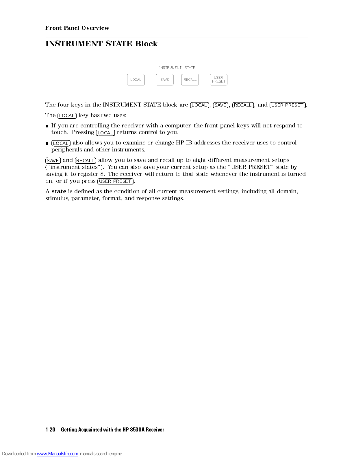
INSTRUMENT STATE Block
The four keys in the INSTRUMENT STATE block are
The
4
5
LOCAL
If you are controlling the receiver with a computer, the front panel keys will not respond to
touch. Pressing
4
LOCAL
peripherals and other instruments.
4
5
SAVE
(\instrument states"). You can also save your current setup as the \USER PRESET" state by
saving
or
on,
state
A
stimulus
key has two uses:
4
5
LOCAL
5
also allows you to examine or change HP-IB addresses the receiver uses to control
and
4
to
it
you
if
dened
is
parameter
,
RECALL
register
press
5
allow you to save and recall up to eight dierent measurement setups
4
USER
as
,
returns control to you.
receiver
The
8.
.
PRESET
the
format,
5
condition
and
response
of
will
all
return
current
settings
4
LOCAL
state
that
to
measurement
.
5,4
SAVE
whenever
settings
5,4
RECALL
the
including
,
5
, and
4
USER PRESET
instrument
all domain,
turned
is
5
.
the
Getting Acquainted
1-20
with
HP
8530A
Receiver
Page 31

AUXILIARY MENUS Block
Front Panel Overview
The \AUXILIARY MENUS" contain the
4
5
COPY
4
DISC
or select an external disc drive.
4
SYSTEM
or wide IF bandwidth, or control phase locking.
If using remote mixers, you can control the RF-to-LO frequency ratio (to select the desired
harmonic mode) using the Multiple-Source menu.
controls hardcopy output, either printing or plotting.
5
controls saving, loading, viewing, or deleting disc les.You can also format oppy discs,
5
menus control internal functions of the HP 8530. For example, you can select normal
4
COPY
5,4
DISC
5
, and
4
SYSTEM
5
keys.
Getting
Acquainted with
the
HP
8530A
Receiver
1-21
Page 32

Front Panel Overview
Automatic Recall of Instrument Settings
The receiver
between
forth
remembers
settings
Save
the
instrument
feature
This
Channel
Domain
arameter
P
Format
Response (scale
Every
For example, assume you choose the following measurement settings.
mode
Channel 1
Angle Domain
Parameter 3
Log mag (format)
Reference
Scale
automatically
channels
the
all
except
5
stimulus
Recall
or
state
works
or
(1
(Frequency
(1,
display
(any
in
10
0
dB/div
remembers most measurement settings. When you switch back and
domains
,
lower-level settings
settings.)
This
functions
memory
by
2)
3,
2,
and
above list
the
dB
,
or
.
."
assigning
,
Angle
4)
format)
reference
remembers
parameters
,
This feature
ability
hierarchy
a
Time)
or
line)
,
you used
remember
to
to
settings you
all
display
or
last. (This
is automatic
previous
instrument
the
the
formats
make that
,
feature remembers
does
,and
settings
settings
receiver
not
Here
.
lower
are
automatically
measurement
all
require
called \limited
is
you
the
is
the
in
use
to
hierarchy:
hierarchy
.
Now you go to Channel 2 and make completely dierent settings
When you reactivate Channel 1, the settings shown above will automatically
hierarchical memory applies to all the controls in the above list.
The Added Benet of the SAVE/RECALL feature
Stimulus settings are not part of the hierarchical memory explained above.To save stimulus
other
settings
advantage
1-22
along
Getting Acquainted
with all
that saved
is
the
instrument
the
with
HP
settings
8530A
,
states
Receiver
you
can
must
be
use
stored
the
to
SA
disc
.
VE/RECALL
.
resume. This
feature
.
Another
Page 33

Typical Softkey Menu Structure
Front Panel Overview
Each
Each
the
on
Every
choices
the
of
menu
side
softkey
.
function
contains
the
of
when
,
blocks
up
display
pressed,
to
.
contain
eight
Press
either
4
a
MENU
selections
softkey
the
activates
,
that
key
5
corresponding
each
the
to
function,
the
presents
right of
the
or
softkey
one
to
function
presents
menus
of the
you
the
the
on
unlabeled
to
want
level
next
screen.
keys
select.
menu
of
Getting
Acquainted with
the
HP
8530A
Receiver
1-23
Page 34

Page 35

2
Manual Measurement Examples
This chapter gives basic examples of antenna and RCS measurements. The intent is to show
you the overall steps involved in making a measurement, but not to go into great depth on
measurement choices. This chapter also explains simple (but very useful) tasks such as using
markers, nding depth of a null, determining beam width, and displaying more than one
parameter.
After you become familiar with the concepts presented in this chapter, you can read Chapter 4
to learn more advanced measurement skills.
Chapter
Denitions
Antenna
Angle
Frequency
Measurements
RCS
Frequency
domain
Time
Angle
CW
Contents
Important
of
Measurements
measurements
scan
response
response
measurements
Scan
erms
T
measurements
measurements
Measurement Examples
Manual
2-1
Page 36

Angle Scan Measurements
Denitions of Important Terms
It is important that you understand the denition of the following terms
HP 8530A
Channel
Input
Ratio
arameter
P
.
The receiver has two separate, identical measurement
feature is like having two HP 8530 receivers setting next to one another.
When the receiver measures raw data, it makes two identical copies. Each
copy is sent through parallel (identical) data processing paths. Such features
as calibration, Time Domain, display formatting, and trace math can be
performed on one or both paths. Each of the two channels correspond to
one of the data processing paths (refer to Figure 1-5). When you press the
4
CHANNEL 1
Any subsequent changes you make to measurement settings will aect that
channel.
Refers to the four HP 8530A signal inputs (a1, a2, b1, and b2). The term
\input" is also used when referring to the signal inputs of the frequency
converter (HP 8511A/B, 85310A, or other.)
Most often, users want to divide the measured signal of the
signal
or example
(F
reference
rejection
The
measurement.
4
ARAM
P
b2/a1,
a1.
desire
N
N
N
N
N
N
N
N
N
N
SERVICE
N
N
N
N
N
N
N
N
NN
SERVICE
5or4
of the
signal at
errors
of
parameter
are
5
4
so
and
can
ou
Y
view
o
T
.
N
N
N
N
N
N
N
N
N
N
NN
NN
N
N
N
N
N
N
N
3
N
N
N
N
NN
NN
N
N
N
N
N
N
N
N
N
N
N
N
N
PARAMETERS
CHANNEL 2
reference
, selecting
a1.) A
caused
the
is
front
The
the
at
set
or
F
on).
redene
single
a
N
N
N
N
N
N
N
a2
N
N
N
N
N
N
N
,
SERVICE
N
N
N
N
N
N
N
N
N
N
N
N
N
N
N
N
N
NN
NN
N
N
N
5
key, you make that channel the \active channel."
or
,
input.
input,
example
the
N
N
N
N
N
N
N
N
N
N
N
.
This is
b1/a1 would
ratioed measurement
transmitter
the
by
input
or
keys
panel
select
ARAM
N
N
N
N
N
N
N
N
N
N
N
b1
4
N
N
to
,
use
N
N
N
N
4
P
ARAM
keys
the
softkeys
factory
P
input,
NN
NN
called a
divide the
ratio
4
ARAM
P
so
N
ratio
transmit
,
that you
,
,
5
1
dierent
divides
5
1
they
N
N
N
N
N
NN
N
N
N
N
N
N
N
N
N
N
SERVICE
located
,
signal
test
provides common-mode
have selected
4
ARAM
P
input
(ratios)
any
ratio
N
N
N
N
N
N
N
N
N
N
N
N
1
under
N
N
a1
NN
N
N
N
N
,
as they relate to the
channels
ratioed,
antenna,
,
5
2
ratios
two
N
N
N
N
N
SERVICE
P
. The channel
test
input by the
measurement.
the
by
b1
at
drift.
or
for
4
ARAM
P
input
NN
N
N
N
N
N
N
ARAMETER
3
(b1/a1,
b1
inputs
N
N
N
N
N
N
N
N
N
N
N
,
5
by
you
N
N
N
N
N
N
2
and
N
N
N
N
b2
a
NN
N
N
,
4
MENU
5
Manual Measurement
2-2
Examples
Page 37

Angle Scan Measurements
Antenna Measurements
The rst part of this chapter describes the two supported types of antenna measurements:
Angle Scan The HP 8530A can make single-axis angle scan measurements at a
single frequency.You can measure a single angle, or an angle sweep.
Frequency Response This is a measurement at a single angle over a range of frequencies.
When selecting frequencies, you can:
Specify a list of specic frequencies.
Select the start and stop frequencies, and the number of points. The
receiver will pick the individual frequency points in-between.
Note
When this
give the
refers
Softkeys
to
Select a frequency center point, a frequency
of points. The receiver will pick the individual frequency points
throughout the span. This method is useful when you want to look
closely at a smaller portion of the frequency band.
In frequency measurements, triggering should usually be set to
internal triggering.
the
manual instructs
name of
the
are
the functional
4
MENU
shown
key
5
N
LIKE
N
N
N
N
N
N
N
N
you to
located
NN
NN
N
N
N
N
N
N
N
N
N
THIS
block rst.
in
N
N
N
N
N
N
N
.
press one
the
of
example
or
F
STIMULUS
span
4
four
MENU
STIMULUS
,
functional
, and the number
will
,it
5
keys
4
MENU
block.
5
Measurement Examples
Manual
2-3
Page 38

Angle Scan Measurements
Angle Scan Measurements
This tutorial will show you how to make a typical angle scan (pattern) measurement.
Notes Regarding Angle Scan Measurements
The HP 8530 does not send commands to the positioner controller.You must set the start, stop,
and increment angles on the positioner controller directly. The only exception to this is if your
positioner controller is completely manual. To make the measurement, use the positioner
controls to rotate the antenna.
What Triggers Measurements at Each Angle?
On systems NOT equipped with the HP 85370A Position Encoder:
Trigger, measures one data point every time a Record Increment trigger is sent by the
positioner controller. The receiver uses the Record Increment trigger to:
Know when the antenna is at an angle where a data point is to be taken.
Keep track of how many angular data points have been measured, and thus, when the
measurement is nished.
osition
angle
use
4.
settings:
P
angle
angle
(an
internal
It
.
the
90
the
will
with
selected
the
an
position
in
use
(b1/a1)
1
increment
Chapter
the
systems
On
Encoder automatically
time
each
taken).
explained
Example
example
The
Display:
Measured
Angle:
Start
Angle:
Stop
Increment
Frequency: 10 GHz (X-band)
that
positioner
the
Receivers
in
Measurement
arameter:
P
Angle:
that
\External
measurement
knows
reaches
use
Triggering"
Single
aram
P
0
+90
1
equipped
ARE
85370A
HP
increment
encoder
following
The receiver, using External
Encoder:
causes
where
triggering.
a
The
the
data
More
HP 85370A
receiver
point
this
on
to
is
Position
trigger
be
to
subject
is
Manual Measurement
2-4
Examples
Page 39

Angle Scan Measurements
Setup
crosstalk
RF
the
errors,
power
desired
refer
by
value
to
pressing
using
setup
,
5
your
N
N
N
N
N
N
N
N
N
N
select
or
NNNNNNNNNNNNNNNNN
ANGLE
NN
N
N
N
N
1
Measurement
.
reduce
.
Change
.
setup
N
N
.
10
0
Then
dBm.
enter
NNNNNNNNNNNN
level
N
N
N
N
N
N
N
N
N
would
5
Antenna
.
4
DOMAIN
for
N
N
N
N
N
N
NN
N
N
N
N
SOURCE
N
N
N
Typical
Figure
Setup
est
Typical
Figure
You must not connect a signal to the Event Trigger BNC if your system uses the HP 85370A
Position Encoder.
Encoder.
Calibrate
you
If
Chapter 3.
Make
1.
Press
2.
Select angle measurements by pressing
3. Determine
STIMULUS
entry
T
typical
shows
2-1
want
Measurement Settings
4
RECALL
keys
a
Connections to Event Trigger could cause false triggers to the Position
calibrated
make
to
NNNNNNN
NNNNNNN
5
MORE
appropriate
an
4
MENU
for
,
N
N
N
N
N
5
POWER
example
2-1.
gain
RF
N
N
N
N
N
N
N
N
MENU
4
5
1
power
N
N
N
N
N
4
0
measurement
measurements
N
N
,
POWER
4
5
x1
antenna
NNNNNNNNNNNNNNNNNNNNNNNNN
NNNNNNN
FACTORY PRESET
N
N
NN
N
N
N
N
N
N
N
N
N
N
4
5
-
the
Measurement Examples
Manual
2-5
Page 40

Angle Scan Measurements
4. Select angle and frequency settings by pressing the following keys:
4
5090
START
4
5904x15
STOP
STIMULUS
NNNNNNNNNNNNNNNNNNNNNNNNNNNNNNNNNNNNNNNNNNNNNNNNNNNNNNNN
FREQUENCY of MEAS.
4x15
4
MENU
NNNNNNNNNNNNNNNNNNNNNNNNNNNNNNNNNNNNNNNNNNNNNNN
5
,
INCREMENT ANGLE14x15
10
4
5
G/n
4
PARAM 1
5. Set the receiver for the correct triggering mode:
Press:
a. If your systemisequipped with the HP 85370A Position Encoder,press
NNNNNNNNNNNNNNNNNNNNNNNNNNNNNNNNNNNNNNNNNNNNNNNNNNNNNNNN
TRIG SRC: INTERNAL
b. If your system
increment triggering directly front the positioner controller, press
6.
Press
erform the
7. P
a.
Press
b.
If
c.
If
d.
If
e.
If
the
On
8.
5
NNNNNNNNNNNNNN
MORE
4
PRIOR
4
PRIOR
A
Axis
A
Axis
prefer
you
prefer 0
you
positioner
NNNNNNNNNNNNNNNNNNNNNNNNNNNNNNNNNNNNNN
TRIGGER MODE
.
is not
5
MENU
following sub-steps
MENU
your
on
your
on
6
controller:
equipped with the HP 85370A Position Encoder, and gets its record
NNNNNNNNNNNNNNNNNNNNNNNNNNNNN
CONTINUAL
NN
NN
N
N
N
N
N
N
N
N
N
N
N
N
N
N
N
5
ENCODER
positioner
positioner
180
display
to 360
display
.
only
N
N
N
N
N
N
N
N
N
N
N
N
N
N
N
N
N
N
FUNCTIONS
a
uses
a
uses
press:
,
press:
,
you
if
N
N
N
N
NN
NN
N
N
N
single
dual
NN
N
N
N
N
N
N
N
+/-180
NN
have
N
N
N
N
N
N
N
N
N
AXIS
synchro
synchro
N
N
N
N
N
N
N
N
N
N
N
N
N
N
N
N
N
N
N
ANG
N
N
N
N
N
N
N
N
POL
N
N
N
N
N
N
N
N
N
N
the
N
N
N
N
N
NN
NN
N
A
,
press:
,
N
N
NN
NN
N
0to
HP
N
N
N
N
N
N
N
N
MORE
press:
N
N
N
N
N
N
N
N
85370A
N
N
N
N
N
N
.
N
N
SYNCHRO
N
N
N
N
N
DUAL
NN
N
N
N
N
N
N
N
N
N
N
N
360
osition
P
N
N
N
N
N
N
N
NN
NN
N
N
N
N
N
N
N
N
N
N
N
N
N
NNNNNNNNNNNNNNNNNNNNNNNNNN
EXTERNAL
Encoder:
N
NN
NN
N
N
N
N
N
N
N
N
N
N
N
N
N
N
SINGLE
.
N
N
N
N
N
N
N
N
Select manual
a.
b. Some positioner controllers can be \manually programmed" from the front panel
for a semi0automatic measurement. Such units may require you to enter a start,
stop, and increment angle. If you have a controller of this type, enter start, stop,
and increment angle values now. Use the same values you entered into the receiver.
Refer to the instruction manual for the positioner controller if necessary. If you use a
completely-manual
Set the
c.
Note
Manual Measurement
2-6
positioner
(local)
Some positioner controllers express angles from 0 to 360 degrees
than0180 to +180 degrees
positioner to the
set the positioner to 270. This is not a problem if you have the HP 85370A
Position Encoder.
operation.
positioner controller
Axis
controller
Examples
to
equivalent
.
step
this
skip
A.
. If you have a 0 to 360 degree controller
0
start angle
or example
.F
, to get
90
, rather
,setthe
you would
Page 41

Angle Scan Measurements
Choose Display Format
The next step is to choose the way you want data to be displayed. The keys and softkeys in
the FORMAT block control the display format. Choose one of the following:
4
LOG MAG
4
LIN MAG
4
PHASE
4
POLAR MAG
FORMAT
Note that in Angle Domain, 0 degrees is at the top of the display in polar formats. Refer to
4
POLAR MAG
Choose Display Scale and Reference Line Settings
One step 40 dB or 60 dB patterns
ou
Y
Press
Individual
4
SCALE
rst
can
scale
5
5
5
5
4
MENU
5
the
set
can
RESPONSE
the
sets
5
you
,
time
to
values
suit
choose
NNNNNNNNNNNNNNNNNNNNNNNNNNNNNNNNNNNNNNNNNNNNNNN
5
LINEAR on POLAR
NNNNNNNNNNNNNNNNNNNNNNNNNNNNNNNNNNNNNNNNNNNNNNN
and
LINEAR on POLAR
display up
N
N
N
NN
NN
NN
NN
N
N
N
MENU
scale
vertical
should
for
actual data.
the
NN
N
N
N
40
reference
and
graticule
estimate
display scale
for 40
N
N
N
N
NN
NN
NN
dB
in the
dB or
NN
NN
N
N
N
N
N
N
N
N
N
N
N
N
N
PATTERN
controls
scale
(roughly)
After
.
displays logarithmic magnitude in Cartesian format.
displays linear magnitude in Cartesian format.
displays phase in Cartesian format.
displays logarithmic magnitude versus angle.
displays linear magnitude versus angle.
HP 8530A Keyword Dictionary
one
N
N
N
N
N
N
N
N
N
N
PATTERN
in
N
N
N
N
N
N
N
When
and
N
N
NN
NN
NN
NN
minimum
N
N
N
.
making
is
60 dB
N
N
N
N
N
NN
NN
or
dB/division.
in
the
the
patterns
NN
NN
NN
NN
N
N
N
dB
60
maximum
measurement
step:
done
you
for details.
measurement
a
can
levels
readjust
power
.
for
Then
the
you
display
selects
4
Press
display
The
specify
Press
If you had pressed
the display.You can place the reference line anywhere you wish by pressing:
4
SCALE
display
.
4
REF
REF POSN
5
the
to
has
Change
ALUE
V
5n4x15
4
5
4
bottom.
This
4
.
5
x1
reference line
a
of
value
the
4
10
0
5
, wherenis a number from 0 (bottom of the display) to 10 (top).
.
5
x1
NNNNNNNNNNNNNNNNNNNNNNNNNNNNNNNNNNNNNNNNN
40 dB PATTERN
4 dB/division,
. This
reference
the
or
line
NNNNNNNNNNNNNNNNNNNNNNNNNNNNNNNNNNNNNNNNN
60 dB PATTERN
which
represents
to
line
provides
specic
a
dB as
0
10
, the reference line is now at the top of
40
power
follows:
level,
from
dB
the
which
top
of
you
the
can
Measurement Examples
Manual
2-7
Page 42

Angle Scan Measurements
Measure the Antenna
To measure the antenna under test:
1. Press MEASUREMENT
beginning of the angle scan. Press this key before making every angle scan measurement.
Hint
2. Using the positioner controller front panel controls, move the antenna to the start angle.
You should always move the positioner about 3in front of the start angle. When the
receiver displays
example the
the
Move
3.
positioner
Results
This note applies to systems that are NOT equipped with the HP 85370A
Position Encoder.
Sometimes positioner controllers \skip" a trigger pulse during the
measurement. If this happens, the measurement will stop near the end of the
scan, waiting for the nal trigger pulse (or pulses). If you try to make another
angle scan, the receiver will measure the \missing" points and then stop taking
data. MEASUREMENT
measurement, and starts the next scan properly (at the start angle). This is
never a problem if you are using the HP 85370A Position Encoder.
start angle
antenna
.
turns
example
an
for
MOVE
from
NNNNNNNNNNNNNNNNNNNNNNN
RESTART
POSITIONER
0
is
90
0
antenna
. This step ensures that the measurement starts at the
90
,so
+90
to
are
4
RESTART
ANGLE
move the
.
shown below:
The
5
forces the receiver to abandon the previous
FORWARD
positioner
receiver
you
will
have
about
to
measure
gone
enough.
far
93
0
.
antenna pattern
the
In
this
as the
Figure 2-2. Example Antenna Measurement
Manual Measurement
2-8
Examples
Results
Page 43

Aborting a Measurement
Angle Scan Measurements
The MEASUREMENT
start over. When you are in Frequency Domain you can press this key whenever you want.
However, you should be careful when pressing this key in the ANGLE domain. Always follow
this procedure:
1. Stop the positioner controller and prepare it for a new scan.
2. Press
4
RESTART
start of the next scan.
4
RESTART
5
. This will abort the current measurement and return the HP 8530A to the
5
key tells the receiver to abort the current measurement and
Move it back to the start angle.
Measurement Examples
Manual
2-9
Page 44

Frequency Response Measurements
Frequency Response Measurements (at a Fixed Angle)
This tutorial will show you how to make a typical frequency response measurement. The
example measurement will use the following settings:
Measured Parameter: Param 1 (b1/a1)
Start Frequency: 8.2 GHz
Stop Frequency: 12.4 GHz
Number of Frequency Points: 201
Angle: 0
Calibrate
If you want to make calibrated gain measurements, or reduce crosstalk errors, refer to
Chapter 3.
Choose Measurement Settings
1.
Select Frequency Domain measurements: Press
2.
Set the
frequency sweep
to Step
mode:
Press
4
DOMAIN
STIMULUS
NNNNNNNNNNNNNNNNNNNNNNNNNNNNN
5
FREQUENCY
4
5
MENU
N
N
N
N
N
N
N
STEP
.
N
N
N
N
N
N
N
.
faster
is
N
N
N
NN
N
N
N
N
N
N
system
source
RF
N
N
N
N
N
N
N
NN
5
MORE
4
MENU
5
8.2
5
12.4
mode
receiver
and
than
Ramp
the
to
N
N
N
N
N
N
N
N
N
N
N
N
N
N
NN
N
N
N
N
N
N
N
N
CONTINUAL
an
has
to
mode
ast
\F
in
compatible
is
N
N
N
N
N
4
G/n
4
G/n
4
MENU
NN
of
N
N
N
N
N
N
N
N
N
N
N
N
N
N
N
SYSTEM PHASELOCK
NNNNNNNNNNNNNN
5
MORE
points
5
5
NNNNNNNNNNNNNNNNNNNNNNNNN
5
NUMBER of POINTS
NOTE:
the
frequency-accuracy
point.
3.
Press
If
4.
phase
836xx
If
4
SYSTEM
5. Make sure triggering is set to internal by pressing:
STIMULUS
With internal triggering turned ON, the receiver will not wait for outside trigger pulses
before measuring data points. Instead, it will measure each point at the fastest possible
speed.
Select
6.
Ramp
source
RF
Refer
N
N
N
N
MORE
your
locking
sources
your
number
4
START
4
STOP
STIMULUS
than
This
.
mode
Ramp
Sweep
N
N
N
N
.
and a
8511
HP
Step
up
speed
measurement
turn
,
N
N
N
N
N
N
N
N
N
N
N
N
N
N
N
N
N
NN
NN
N
N
N
N
N
N
NNNNNNNNNNNNNNNNNNNNNNNNNNNNNNNNNNNNNN
TRIGGER MODE
frequency
and
NNNNNNNNNNNNNNNNNNNNNNNNN
possible in
not
is
because
,
description
compatible
measurements
speed
Quick Step
NN
N
N
N
N
N
N
N
N
N
N
N
N
N
N
N
N
N
NN
STEP TYPE:
NNNNNNNNNNNNNNNNNNNNNNNNNNNNNNNNNNNNNNNNNNNNNNNNNNNNN
TRIG SRC INTERNAL
settings
NNNNNNNNNNN
201
and
N
N
N
in
NN
N
N
N
N
N
Step
Chapter
HP
Quick Step
mode ON
N
N
N
N
N
N
NN
by
requires two
,but
step
BNC cable
many ranges
phase
mode
for
4
836xx
. Refer
N
N
N
N
N
N
N
N
QUICK
pressing the
source
to
mode"
by
NN
N
N
N
N
N
N
N
interconnections between
has
mode
Step
.
locks at
more information.
,
list
the
in
pressing:
following
each frequency
can
you
compatible
of
Appendix
keys:
use
Quick
B.
better
Step
HP
Note
7.
2-10
Select
the
Manual Measurement
When you select dierent frequency values for your measurement, HP 836xx
RF sources use the rst sweep to accurately phase lock the RF frequencies.If
application
your
actual
the
parameter
measurement.
you
Examples
want
demands
view
to
measurement
high
example
for
,
press
,
speed,
4
ARAM
P
subsequent
use
.
5
1
sweeps
for
Page 45

Frequency Response Measurements
8. Determine an appropriate RF power level for your setup.
To change RF power, press:
STIMULUS
9. Set the positioner controller so the antenna is at the desired angle.
Choose Display and Reference Settings
4
MENU
NNNNNNNNNNNNNNNNNNNNNNNNNNNNNNNN
5
POWER MENU
NNNNNNNNNNNNNNNNNNNNNNNNNNNNNNNNNNNNNNNNNNNN
,
POWER SOURCE 1
. Then enter the desired value.
Choose a data presentation format, scale, and reference value/position as explained in \Angle
Scan Measurements". The two polar display keys,
dierently in Frequency Domain than they do in Angle Domain. Refer to
NNNNNNNNNNNNNNNNNNNNNNNNNNNNNNNNNNNNNNNNNNNNNNN
LINEAR on POLAR
Choose Sweep Type
The receiver will already be measuring data. By default, the receiver will measure the
frequency band repeatedly.You can save data to a disc at any time, refer to Chapter 6 for
instructions.
to
If you
Press
receiver
receiver
left-hand
Choosing
The
want
STIMULUS
underline
will
in
is
side
the
dierent
oint
Single
Ramp
Step Sweep
Frequency List
P
Sweep
measure
4
MENU
Hold
the
of
Best
sweep
mode
mode
mode
mode
in the
mode
display
Sweep
modes
HP 8530A Keyword Dictionary
time:
a
N
NN
N
N
N
N
N
SINGLE
N
N
N
N
N
N
N
N
N
is not
Mode
at
N
N
N
NN
NN
NN
NN
N
N
N
N
softkey
STIMULUS
.
making
receiver is
the
for
The
Y
when
measurements
our
one
N
N
N
N
5
MORE
the
,and
sweep
NN
N
N
N
N
N
N
N
N
N
N
HOLD
when
under
4
POLAR MAG
for details.
take
receiver
Measurements
4
MENU
will
measurement
the
Hold
in
are:
5
.
mode
The
NNNNNNNNNNNNNNNNNNNNNNNNNNNNNNNNNNNNNNNNNNNNNNN
5
and
LINEAR on POLAR
sweep
one
nished.
is
will
H
letter
.
4
POLAR MAG
stop
then
,
This
appear
, operate
5
and
The
.
means
on
the
the
These modes are explained in \Frequency Domain Measurement Tutorial" in Chapter 4.
Choosing Single or Continual Measurements
You can also choose between single or continual measurements, using STIMULUS
NNNNNNNNNNNNNNNNNNNN
SINGLE
N
N
N
N
N
N
NN
N
N
N
N
N
N
SINGLE
NNNNNNNNNNNNNNNNNNNNNNN
NNNNNN
CONTINUAL
or
N
N
N
N
N
N
NNNNNNNNNNNNNNNNNNNNNNNNNNNNN
CONTINUAL
makes
switches to Hold mode
repeats the measurement continuously
.
single measurement.
a
, and the letter
When
measurement
the
H
appears on the display
.
Manual
done
is
Measurement Examples
the
.
4
MENU
receiver
NNNNNNNNNNNNNN
5
MORE
:
2-11
Page 46

Manual RCS Measurements
Radar Cross Section Measurements
This section describes how to make manual Radar Cross Section (RCS) measurements. The
HP 8530A can be used to perform these basic RCS measurements directly, using only the front
panel controls:
Frequency Domain This measurement domain will determine the reection from
a stationary target versus frequency.You can measure the
reection over a frequency sweep, at a CW frequency,or a
specic list of frequencies.
Time Domain Time domain (optional) can be used to measure the reections
of the target over time, giving the down range RCS response.
The HP 8530A will rst measure in the Frequency Domain
and then compute the Time Domain response using an inverse
Fourier Transform.
Software Gating Time domain gating can be used to remove unwanted
RCS responses in both time and Frequency Domain RCS
measurements. The gating function can \lter out" various RCS
error signals such as feed coupling, monostatic antenna return
.
made
frequency
target
the
This
.
to
,
up
pattern
the
than
showing
This
.
trigger
and
measurement
domain
angle
an
except
receive
antenna.
RCS
is
the
of
done
a
is
Angular
CW Measurements
, chamber
loss
An angle
target
by
the
similar
measurement
positioner
domain measurement
versus
positioner
a
using
receiver
concept,
in
moves
reections and
rotation
each
at
of
angle
system
measurement
hardware
and
antenna
an
target,
the
range clutter
can be
CW
a
at
move
to
angle
set
radiation
rather
the
Since
following
tutorials
following
The
antenna
section
this
In
Domain
Time
tutorial
builds
measurement
starts
upon
procedures
will use
we
response
Frequency
a
with
previous
the
assume
also
section earlier
some of
calculated
is
example
that
in this
the skills
from
Domain
.
have
you
chapter.
and
Frequency
the
measurement.
RCS
and
read
procedures
Domain
become
discussed
measurement,
of
Each
familiar
.
earlier
the
with
the
following
the
Manual Measurement
2-12
Examples
Page 47

Manual RCS Measurements
Frequency Domain Measurements
The following tutorial will show you how to make a typical Frequency Domain RCS
measurement. The example measurement will use the following settings:
Measurement Parameter: Param 1 (b1/a1)
Start Frequency: 8.2 GHz
Stop Frequency: 12.4 GHz
Number of Frequency Points: 801
Target Angle: 0
Measurement
Typical
Figure
Typical Test Setup
Figure 2-3 shows a typical RCS setup. Notice that the reference signal is coupled from the RF
source rather than using a reference antenna as in an antenna measurement. This is a normal
quasi-monostatic
a
conguration
for
used
Calibrate
Calibrate using the instructions provided in \RCS Calibration
for
monostatic
a
range
2-3.
and
.
RCS
bistatic
antenna
range
Setup
directional coupler
dual
A
.
" in Chapter 3.
Measurement Examples
Manual
is
2-13
Page 48

Manual RCS Measurements
Choose Measurement Settings
1.
Select Frequency Domain measurements: Press
2.
Set the frequency sweep to Step mode: Press STIMULUS
NNNNNNNNNNNNNN
The
RAMP
sweep mode may be used with some frequency converters such as the HP
8511A/B if the proper rear panel connects are made. Refer to the Ramp Sweep mode
description in Chapter 4 for more information.
NNNNNNNNNNNNNN
3.
Press
4. Make sure the triggering is set to internal by pressing:
STIMULUS
With the trigger set to internal the receiver will not wait for an external trigger signal
before taking any data points. Instead, it will measure each point at the fastest possible
speed.
Also make sure that the
NNNNNNNNNNNNNNNNNNNNNNN
PARAM
Select
5.
keys:
NNNNNNNNNNNNNNNNNNNNNNNNNNNNN
MORE
CONTINUAL
4
MENU
and
,
3
measurement
the
NNNNNNNNNNNNNN
5
MORE
NNNNNNNNNNNNNNNNNNNNNNN
PARAM
.
NNNNNNNNNNNNNNNNNNNNNNNNNNNNNNNNNNNNNN
TRIGGER MODE
NNNNNNNNNNNNNNNNNNNNNNNNNN
STIMULUS
not.
are
4
frequency
NNNNNNNNNNNNNNNNNNNNNNNNNNNNNNNNNNNNNNNNNNNNNNNNNNNNN
TRIG SRC INTERNAL
key is underlined, but the
range and
4
DOMAIN
the number
NNNNNNNNNNNNNNNNNNNNNNNNNNNNN
5
FREQUENCY
4
5
MENU
NNNNNNNNNNNNNNNNNNNNNNN
PARAM 1
of points
.
NNNNNNNNNNNNNN
STEP
.
,
by pressing
NNNNNNNNNNNNNNNNNNNNNNN
PARAM 2
the
,
following
4
ART
ST
5
STOP
PARAM 1
the
12.4
5
target
4
STIMULUS
Note
Select the
6.
4
7. Determine an appropriate RF power level for your range. Most RCS setups use the
maximum available power.To change RF power: Press STIMULUS
NNNNNNNNNNNNNNNNNNNNNNNNNNNNNNNNNNNNNNNNNNNNNNN
POWER SOURCE: 1
Set
8.
Choose Display F
Choose a data presentation format, scale
Scan Measurements".
5
G/n
4
5
G/n
4
MENU
When
frequency
high
measurement.
parameter you
place
in
N
N
N
N
N
N
N
N
N
N
N
N
5
NUMBER
using
measurement
. Then enter the desired value, or use the knob.
at the
,
ormat
N
N
N
N
N
NN
N
N
N
N
N
OF
an
change
wish to
N
N
N
N
N
N
N
N
N
N
N
POINTS
8360
HP
is
accuracy
desired
N
N
N
N
N
N
NN
N
N
N
N
N
N
N
used
measure,
N
N
N
N
N
N
N
N
N
N
N
801
any
source,
family
positioner
, and reference value/position as explained in \Angle
RF
accurately
to
required,
is
press:
angle
the
phase
use
.
the
lock
second
the
sweep
rst
after
frequencies
RF
sweep
4
MENU
your
for
NNNNNNNNNNNNNNNNNNNNNNNNNNNNNNNN
5
POWER MENU
4
8.2
5
If
.
,
Manual Measurement
2-14
Examples
Page 49

Manual RCS Measurements
Measure the Target
The receiver will already be measuring RCS data. By default, the receiver will measure the
frequency band repeatedly. After the target has been measured, you can stop taking data by
pressing:
NNNNNNNNNNNNNN
STIMULUS
or
You can make a single sweep measurement by pressing:
STIMULUS
You can now remove the target or make other changes while performing other functions
and data processing on the RCS measurement. An example of a Frequency Domain RCS
measurement is shown in Figure 2-4.
After the measurement is nished you can save the data to disc, refer to Chapter 6 for
instructions.
4
MENU
4
MENU
5
5
MORE
NNNNNNNNNNNNNN
MORE
NNNNNNNNNNNNNN
HOLD
NNNNNNNNNNNNNNNNNNNN
SINGLE
Figure 2-4.
If you want to measure
Press STIMULUS
receiver
receiver is in Hold mode
left-hand side of the display when the receiver is in Hold mode.
Choose
The
Single P
Ramp Sweep
will underline the
the
dierent
oint
4
Best
sweep
mode
mode
one sweep at a time:
NNNNNNNNNNNN
NN
5
MENU
MORE
, and is not making measurements
Sweep
modes
Typical
NN
NNNNNNNNNNNNNN
HOLD
Mode
under
Measurement
. The letter
Manual
, then stop
H
will appear on the
Measurement Examples
. The
5
are:
Domain
Frequency
RCS
NNNNNNNNNNNNNNNNNN
SINGLE
. The receiver will take one sweep
softkey when the measurement is nished. This means the
Measurements
our
Y
for
STIMULUS
4
MENU
2-15
Page 50

Manual RCS Measurements
Step Sweep mode
Frequency List mode
Refer to \Frequency Domain Measurement Tutorial" in Chapter 4 for information on these
modes.
Choose Single or Continual Measurements
You can also choose between single or continual measurements, using STIMULUS
NNNNNNNNNNNNNNNNNNNN
SINGLE
NNNNNNNNNNNNNNNNNNNN
SINGLE
NNNNNNNNNNNNNNNNNNNNNNNNNNNNN
CONTINUAL
Using Markers
Markers can be used to give detail of specic points on the trace.For example, to show the
largest RCS response, press:
4
MARKER
NNNNNNNNNNNNNNNNNNNNNNNNNNNNN
or
CONTINUAL
NNNNNNNNNNNNNNNNNNNNNNNNNN
5
MARKER 1
.
makes a single measurement. When the measurement is done the instrument
switches to Hold mode.
repeats the measurement continuously.
NNNNNNNNNNNNNN
NNNNNNNNNNNNNNNNNNNNNNNNNNNNNNNNNNNNNNNNNNNNNNNNNNNNN
MORE
MARKER to
MAXIMUM
4
MENU
NNNNNNNNNNNNNN
5
MORE
:
Time
The
the
Converting
o
T
4
DOMAIN
or
F
Manual
such as:
Choose the Display Format
ou
Y
4
LIN
Since you are now in the Time Domain, the
rather than frequency
adjust or measure in time:
Domain
previous
down
convert
detailed
may
MAG
4
START
4
STOP
4
CENTER
4
5
SPAN
4
MARKER
Frequency
range
the
to
N
N
N
N
NN
NN
N
N
N
N
N
5
TIME
information
. This manual discusses important factors that aect a Time Domain measurement,
Alias-Free Range,Range Resolution,Response Resolution
to
wish
4
,
5
LOG
5
5
5
5
Measurements
Domain
response
RCS
to
N
N
N
N
N
BAND
MAG
Time
Time
N
N
N
N
N
N
N
N
set
5
Domain
Domain,
N
N
N
N
N
N
N
N
N
N
NN
NN
N
N
N
N
PASS
on
display format.
the
FORMA
or
. This means that the following keys now
measurement
be
can
press:
Domain,
Time
4
T
MENU
seen.
The
N
N
N
N
5
REAL
N
converted
be
now
can
Operating
8530
HP
the
see
common
most
N
N
N
N
N
N
N
NN
.
X-axis of the data display is now showing time
formats
into
Programming
and
,and
Impulse Waveforms
Domain
Time
for
aect the Time Domain, and
Domain.
Time
are:
Thus
.
,
,
example
an
As
converted
been
Manual Measurement
2-16
of
into
Time
a
Examples
measurement,
RCS
an
Domain
Figure
the
measurement
Frequency Domain
2-4
and
shown
in
Figure
measurement
.
2-5
has
Page 51

Manual RCS Measurements
Measure the Target
The display is now showing the measured Time Domain response. Markers can be used to nd
the magnitude and the location of each reection.
Using
Markers
earlier
display
the
can
in
is
this
in
Markers
be
now
chapter
Angle
the
Figure
used to
learn
to
Frequency
,
Typical
2-5.
measure each
use
to
how
Time
or
,
RCS
the
of
this
domain.
Domain
Time
responses
markers
Measurement
See
.
The markers
.
\Using
work the
Markers"
same
Chapter
in
if
5
the
Manual
Measurement Examples
2-17
Page 52

Manual RCS Measurements
A Quick Display Adjustment
If the Time Domain display has not already been adjusted in an earlier measurement, the
following is a quick method to get a good data display.
To adjust the magnitude response so that you can see the data, press:
4
5
AUTO
To make sure that you are getting all of the data on the time axis, set the STOP time well
beyond the last time response. A good example is:
4
5
300
4
5
STOP
Press
4
AUTO
Look for the rst point at which the response starts repeating itself (this is due to aliasing).
Figure 2-6 shows an example of this.Adjust the stop time to this point by:
for a 150 foot range.
G/n
5
again to make sure all of the response data can be seen on the display.
4
MARKER
Use the knob to move the marker to just before the start of the repeating response, or to the
last point that there is an RCS response.
Press:
The
4
SCALE
5
4
STOP54=MARKER
4
,
REF V
will
ALUE
Display
5
now
,
5
be
and
5
.
showing
others
the full
desired.
as
RCS response
.Y
ou can
now
adjust
the
4
START
5
,
4
STOP
,
5
Figure 2-6. Time Domain Measurement Showing Aliasing
Manual Measurement
2-18
Examples
Page 53

Manual RCS Measurements
Improving RCS Measurement Accuracy
Many of the RCS responses are due to error signals and not due to the target response. Some
of the error signals are; coupling, monostatic antenna return loss, chamber reections and feed
clutter. An RCS calibration can remove or reduce some of these errors. Time domain
can also be used to reduce some of the errors, such as bistatic coupling, antenna return loss,
and chamber reections.
Gating works like a Time Domain \band pass" lter. The gate is placed around the response
that you wish to keep, the gate is turned \ON", and the responses outside of the gate are
ltered out. Just like a frequency band pass lter, gating has time response sidelobes, lter
skirt, and in-band ripple.For detailed information on gating, see the Time Domain section in
the
HP 8530 Operating and Programming Manual
Using Gating
To show how to use the gate, we will use the earlier RCS Time Domain example.To get to the
gating softkeys, press:
4
DOMAIN
the
Use
around
NNNNNNNNNNNNNNNNNNNNNNNNNNNNNNNNNNNNNNNNN
5
TIME BANDPASS
N
N
N
N
N
N
N
N
N
N
N
N
N
N
N
N
N
NN
NN
NN
N
N
N
N
N
N
N
GATE:
the response
START
NNNNNNNNNNNNNNNNNNNNNNNNNNNNNNNNNNNNNN
SPECIFY GATE
N
NN
N
N
that
and
N
you
N
STOP
N
N
N
N
N
NN
NN
NN
N
wish
keys
to
or
keep
the
(normally
NN
NN
NN
N
N
N
N
N
N
N
CENTER
.
N
N
N
N
N
N
N
and
target
the
N
N
N
N
N
N
N
SPAN
NN
N
NN
NN
keys
response).
to
center
the
Gating
gate
ags
A Measurement Showing the Gate Placed Around the Response
Now turn the gate \ON" by pressing:
N
N
N
N
N
N
N
N
N
N
N
N
N
N
N
N
N
N
NN
N
N
N
ON
GATE
Figure 2-7.
Manual
Measurement Examples
2-19
Page 54

Manual RCS Measurements
Figure
responses outside
the
o
that
will
how
the
show
,
NNNNNNNNNNNNNNNNNNNNNNNNNNNNNNNNNNNNNN
5
SPECIFY
MENU
NNNNNNNNNNNN
5
all OFF
NNNNNNN
5
DISPLAY MODE
side
by
in
work
also
receiver
both
use
Frequency
dierences
channels
various
the
of
.
more
and
GATE
N
N
N
N
N
N
N
N
NN
N
N
N
N
N
N
N
N
N
N
N
NN
N
5
FREQUENCY
NNNNNNNNNNN
NNNNNNNNNNNNNNNNNNNNNNNNN
.
NNNNNN
NNNNNNNNNNNNNNNNNNNNNNNNNNNNNNNNNNNNNNNNNNNNNNNNNNNNN
GRATICULE OVERLAY
Frequency
the
channels
Time
and
between
receiver
the
of
display
NNNNNNNNNNNNNNNNNNNNNNNNNN
N
NN
N
N
NNNNNNN
OFF
GATE
NNNNNNNNNNNNNNNNNNNNNNNNN
DUAL CHANNEL
Notice
Gating
shows
Viewing
T
measurement
adjustment
parameter
To set up for this example, return to the basic RCS measurement by turning gating o, markers
o, and selecting Frequency Domain.
Press:
4
DOMAIN
4
PRIOR
4
MARKER
To display both measurement channels
4
DISPLAY
You can also press
side
2-8.
gate
the
of
Domain
show
to
Domain
signal
gated
a
The
.
parameters
, press:
NNNNNN
or
have
reduce
to
the
Gating
and
measurement
two
such
,
NNNNNNNNNNNNNNNNN
SPLIT
been
dierences
un-gated
an
scale
as;
, to view the two traces superimposed, or
Turned
Gate
The
ON
removed.
response
made
channels
, format,
errors too
by using
signal we
allow independent
domain (except
The
.
the
are going
next
gate
to
section
.
use
angle),
both
the active
is
you
1
make
will
Examples
Currently
changes
any
4
CHANNEL
2-20
2
Manual Measurement
channel
.
5
aect
channel
channel.
that
(notice
T
the
make
o
lit
LED
channel
above
4
the
the active
2
CHANNEL
channel
5
1
key),
press:
and
Page 55

Manual RCS Measurements
Now make the channel 2 display just like the channel 1 display.To do this use the
4
5,4
SCALE
you will notice that both channels display the same information.
Now change both channels to the Time Domain. Notice that you can change the domain in
both channels separately. This allows you to display the frequency response on one channel
and the time response on the other.
Press:
4
CHANNEL 154DOMAIN
4
CHANNEL 254DOMAIN
Also notice that channel 1's Time Domain display is set for the same settings that were made
earlier. Now make channel 2's Time Domain response display the same as channel 1.
Now turn on the gating around the target response in channel 2. Again notice that the gate is
still in the same place we left it earlier in this example.
Press:
NNNNNNNNNNNNNNNNNNNNNNNNNNNNNNNNNNNNN
N
SPECIFY GATE
ou
Y
shows
can
an
REF VALUE
now
example
5,4
5
5
NNNNNNNNNNNNNNNNNNNNNNN
GATE ON
compare
of
5
REF POSN
NNNNNNNNNNNNNNNNNNNNNNNNNNNNNNNNNNNNNNNNN
TIME BANDPASS
NNNNNNNNNNNNNNNNNNNNNNNNNNNNNNNNNNNNNNNN
N
TIME BANDPASS
the
this
,and
dierence
.
4
FORMAT
between
5
keys. If you press the
and ungated
gated
the
NNNNNNNNNNNNNNNNNNNNNNNNNNNNNNNNNNNNNNNNNNNNNNNNNNNN
N
GRATICULE OVERLAY
responses.
4
PARAM
Figure 2-9
5
,
key
Figure 2-9. Dual
Now change both channels back to the Frequency Domain, leaving the gate ON in channel 2,
press:
N
N
N
N
N
N
N
N
N
N
N
N
N
N
4
CHANNEL
4
CHANNEL
4
5
2
DOMAIN
N
NN
N
N
N
N
5
FREQUENCY
1
N
5
FREQUENCY
N
N
N
N
N
N
N
N
N
N
N
N
N
N
N
N
N
N
N
N
N
N
Display with Time Domain
N
N
N
NN
N
N
N
N
N
N
N
N
N
Manual
Measurement Examples
2-21
Page 56

Manual RCS Measurements
Notice the changes in channel 2 as compared with channel 1. Channel 2 has many of the
RCS responses reduced by using the gating capability of the receiver. An example of this is in
Figure 2-10.
Dual
Figure
into
go
to
have
don't
ou
Y
the
a
N
N
prior
you
N
N
N
N
N
Set
wish
N
NN
NN
NN
NN
N
knowledge
N
N
N
N
N
N
N
N
NN
Frequency
Domain,
Then,
4
DOMAIN
without ever going into the Time Domain.
Domain.
by
or
whenever
N
N
N
N
N
N
N
N
N
NN
NN
5
SPECIFY GATE
2-10.
Domain to
Time
gate
turn
to
N
N
N
N
N
N
N
N
N
N
N
N
N
N
NN
GATE ON
at
N
N
of
N
on
NN
the
where
the
proper
Display
turn ON
location, either
the start
press:
,
gate
with Time
gate
the
and stop
Domain
are
you
if
by adjusting
point
only
would
measuring
gate
the
the
for
be
in
in
gate
the
Time
.
Manual Measurement
2-22
Examples
Page 57

3
Antenna and RCS Calibration
This chapter explains antenna and RCS calibration features of the HP 8530A. Network analyzer
calibration features are documented in the
Chapter Contents
What is Calibration?
Calibration Requirements
Calibration Menu Map
Antenna
Standard
erforming
P
RCS
Calibration
Gain Antenna
an
Calibration
Antenna
Denitions (les)
Calibration
HP 8530A Operating and Programming Manual
.
Antenna
and RCS
Calibration
3-1
Page 58

Calibration Fundamentals
Information Pertaining to All Calibration Types
What is Calibration?
Calibration, regardless of the exact type, reduces repeatable systematic errors caused by the
system, the chamber, or the antenna range.To achieve this, the receiver measures one or more
standards of known characteristics. During calibration, the receiver:
1. Measures the standard.
2. Compares the results to the known characteristics of that standard.
3. Calculates the exact amount of inaccuracy, and how much the measurement data must be
adjusted to compensate for it. The adjustment values are called \error coecients."
4. Stores the error coecients in memory.
When actual measurements are made, the calibration feature subtracts the error coecient
values, making the measurement much more accurate.
The HP 8530A can perform three types of calibration:
expressed
Antenna
Calibration
Antenna
dBi
in
gain
frequencies
system.
calibration
(dB
antenna
relative
with
used
is
allows
an isotropic
to
known
transfer
a
as
measured data
radiator). A
dened gain
or
standard
to be
standard
values at
to calibrate
specic
the
Calibration
RCS
Network Analyzer
Response
a
using
Response
calibration
the
empty
clutter
expressed in
Calibration Network
systematic errors
A network
your calibration standards to the measurement of your
device. Network analyzer calibration standards are supplied
in a \calibration kit" which must be purchased separately.
Calibration kits are made for specic frequency ranges and
connector types.
antenna
.
Background
and
calibration
portion
After
analyzer calibration
analyzer calibration
target
the
of
target.
chamber
performing
dBsm (decibels
The
during network
calibration
known
of
calibration
Background
characterize
to
RCS
an
square
per
greatly
transfers the
errors
reduces
radar
measures
portion
calibration,
meter).
reduces
analysis measurements
range
section.
cross
the
measures
compensate
and
measurements
repeatable
accuracy
reections
The
of
the
for
are
.
of
Calibration
3-2
Antenna and
RCS
Page 59

Calibration Fundamentals
Calibration Requirements
Calibration issues become much simpler if you calibrate using the same equipment and
instrument settings that you plan to use during the measurement.
Use the Same Equipment Setup in the Measurement
You
must
calibrate using the same adapters and cables that will be used for the measurement.
If the adapters or cables are changed between calibration and measurement, unpredictable
errors will result due to the fact that the error coecients determined during calibration are
incorrect for the altered setup. Even disconnecting and reconnecting the same adapter can
cause inaccuracy. If you change the setup, you must perform the measurement calibration
procedure again to calculate appropriate error terms for the new setup.
Settings You Can Change after Performing a Calibration
1. You can perform a network analyzer calibration in the frequency Domain, then change to
time domain, and the calibration will remain valid.
2. You can calibrate using a specic number of points, then make a measurement using a
.
points
smaller
Y
3.
or
some
again.)
ou
can
Time
HP
number
perform
Domain,
8530
of
an antenna
the
and
receivers
calibration in
calibration
the
turn
still
will
calibration
the frequency
valid.
be
must
ou
Y
.
OFF
domain, then
change
you
(If
manually
change
the
to
turn
the
to
Angle Domain,
calibration ON
the
Angle
select
(in
receivers
8530
Angle
in
The
, adapters
Domain.
Consideration
consideration.
important
situations
, and so forth, connected in one specic
can
ou
(Y
require
to
thing
where
a calibration applies to a specic
redene
invalid
any
(Some
angle
will
calibration
HP
while
special
results.
avoid
and
valid.
be
swept
perform
can
ou
Y
4.
Single
ON again.)
5. Y
Setting
Other
Changing Parameter
The HP 8530A automatically turns calibration OFF if you change parameter. However,it
allows you to turn the calibration ON again for the new parameter. If you are not careful,
this can result in invalid data. There are situations (explained below) where you can change
parameter
must
The
To understand the considerations involved, remember that
hardware
way).
up, the calibration will be valid.
For example, assume you originally connected the equipment to inputs b1 and a1, and
performed the calibration using b1/a1 ratio.You can select any parameter key that is currently
dened
b1/a1.)
frequency
change
can
ou
Changes that
settings can
and
when
know
instrument will
setup (a specic collection of cables
As long
b1/a1
as
a
measurement.
start
be changed,
valid
get
results
the
not
as the parameter you select will measure that equipment as it was originally set
the calibration
and
frequency
stop
and
Require Special
but require
measurement
are valid,
you.
warn
sweep
Step
or
Ramp
mode),
to
you
remember
data
parameter
turn
then
the
that
is
would
key
calibration
you
result.
be
to
a
Antenna
and RCS
Calibration
3-3
Page 60

Calibration Fundamentals
Changing Stimulus Values
Changing any of the following settings will cause the message
INVALID
Source Power
Power Slope
Dwell Time
Sweep Time
Sweep Modes
Trim Sweep Value
Settings that should not be changed
Selecting a Dierent Frequency Range
If you have performed any type of calibration across a frequency range, and then change
frequencies, calibration is automatically turned O, and
Selecting
you
If
greater
automatically
to be displayed. Calibration remains ON.
oints
P
Greater
a
calibrate
number
using
points
of
turned
Number
certain
a
If
.
and
O,
of
number
attempt
you
CORRECTION
of
points
to
,
select
RESET
cannot
you
greater
a
displayed.
is
CAUTION: CORRECTION MAY BE
CORRECTION RESET
perform
number
a
of
is displayed.
measurement
calibration
,
points
using
a
is
veraging
Using
or
F
device
Hewlett-P
of
accomplished
factor
If you are using averaging
If averaging is ON during calibration, then the correct number of measurements needed
to provide fully averaged data are automatically taken. For Ramp sweeps this means that
n+1 sweeps, where n is the current averaging factor, are taken. For Step,SinglePoint, or
Frequency
averages).
A
calibrations
all
measurement.
ackard
calibration
the
the active
as
by
List,
the
use
,
general,
In
recommends
calibration
RCS
(in
turning
each
A
function during
data
or
same
that
veraging
is
point
averaging
an
increase
is
before
averaging
the
n
greater
use
you
this
ON
the calibration.
averaged
factor
factor
averaging
the
background
beginning
times (where
the
than
16
or
8
of
factor
calibration).
calibration,
the
is
n
will
for
for
selected
be
most
for
used
measurements
isolation
the
can
This
leaving
then
number
the
portion
easily
be
averaging
of
.
Calibration
3-4
Antenna and
RCS
Page 61

Calibration Fundamentals
Figure 3-1. Cal and Cal Type Menus
Antenna
and RCS
Calibration
3-5
Page 62

Calibration Fundamentals
Specic Calibration Procedures
The following pages contain information about specic types of calibration, including
step-by-step procedures on performing calibrations.
The receiver provides the following calibration types:
Antenna Calibration
RCS Calibration
Network Analyzer Calibration (only described in the operating and programming manual)
Response Calibration
Response and Isolation Calibration
1-Port Calibration
Calibration
3-6
Antenna and
RCS
Page 63

Antenna Calibration
Antenna Calibration
Antenna calibration allows measured data to be expressed in dBi (dB relative to an isotropic
radiator). A standard gain antenna with known or dened gain values at specic frequencies is
used as a transfer standard to calibrate the system.
Calibrating with a standard gain antenna corrects for the transmission response errors.
An optional part of antenna calibration is an \isolation calibration." This calibration reduces
crosstalk errors between input channels. The isolation cal requires a high quality RF load as a
calibration standard. The load you need is determined by the connector type and frequency
range of your system.
Important Terms
Cal \Cal" is an abbreviation for \Calibration."
Cal Denition A cal denition is an ASCII le you create using a text editor. It contains
theoretical or measured frequency and gain values for the standard gain
antenna. You can create the le using any computer-based text editor
which can save text in plain ASCII format. The le can then be loaded into
Antenna
Denition
receiver
the
\antenna
data
gain
The
denition."
a
from
denitions
a
for
or
DOS
."
specic
disc
LIF
standard
.
A
gain
denition
cal
antenna
contains up
called
is
\antenna
an
to seven
more
over
the
the
sets
a
gain
antenna
These
."
nal
can
range
be
of
.
standard
calibration,
which,
results
units
.
Domain,
the
compared
is
internal
an
in
when
antenna calibration,
In
.
antenna gain
of
Domain.
which
nished
Set
Cal
Angle
If you perform a calibration while in angle domain, the calibration will be at one frequency.
(Angle Domain makes measurements at only one frequency.)
If you perform a calibration while in Frequency Domain, you can calibrate over a range of
frequencies.
Using a
HP recommends
frequencies.You can then switch to Angle Domain, and pick any of the frequencies from the
Frequency Domain calibration. This gives you instant access to many calibrated frequencies
(one at a time) when in Angle Domain.
Only one limitation applies; the frequency you want to measure (in angle domain) must exist in
the original calibration. The receiver does not interpolate between calibrated frequencies
Here are the basic steps involved in antenna calibration:
Domain
Frequency
A
antenna
denitions
dierences
measurement,
measurement
stored
and
that
calibration
measured
is
Any
.
are
internal
in
Frequency
Domain
calibrate
you
the
result
data
Calibration
data
its
and
dierences
coecients
error
calibrated
in
expressed
is
registers
Domain
Frequency
using
performance
stored
are
in
disc
to
or
Calibrations
Angle
in
During
.
le
the
one
to
set
\cal
subtracted
(dBi). Cal
calibrates
or
register
from
Antenna
and RCS
Calibration
3-7
Page 64

Antenna Calibration
Calibration
3-8
Antenna and
RCS
Page 65

Antenna Calibration
Standard Gain Antenna Denitions
To perform a calibration, the receiver must know the published gain values of the standard
gain antenna. HP has supplied a le containing data for seven Narda standard gain horns.
If You Are Using a Narda Standard Gain Horn that is Already Dened:
Data for Narda models 638, 639, 640, 642, 643, 644, and 645 are supplied in a single cal
denition le.Thisle,
with the HP 8530A. If you are using one of these horns, load
AC_NAR1
, is supplied on the
Antenna/RCS Cal Disc
AC_NAR1
as explained below:
which was shipped
1. Insert the
2.
Press
showing
highlighted.
3.
Press
When you perform the antenna calibration you will see the Narda horns listed in a softkey
menu. Information on the Narda horns is provided at the end of the calibration section. Please
note that your Narda standard gain horn calibration data may be dierent than the data on le
AC_NAR1
Are
ou
Y
If
Create
Denition
save
can
Note
Antenna/RCS Cal Disc
NNNNNNNNNNNNNN
4
5
DISC
AC_NAR1
NNNNNNNNNNNNNNNNNNNNNNNNNNNNN
LOAD FILE
.
Not
own
your
the
at
",
in
text
NNNNNNNNNNNNNNNNNNNNNNNNNN
LOAD
Using
CAL KITS
. Since it is the only cal denition on that disc, it will already be
.
One of
denition
cal
end
ASCII
plain
you
If
more standard
what happens
frequencies?" The
the calibration
the Pre-Dened
chapter
this
of
format.
calibrate
into the HP 8530A's disc drive.
NNNNNNNNNNNNNNNNNNNNNNNNNNNNNNNNNNNNNNNNNNNNNNN
ANTENNA CAL DEF
Narda Horns:
explained
as
le
will
ou
Y
.
frequency
wide
a
over
of
the
.
the
is:
standard
antennas
gain
when
answer
data for
two
, the receiver will display a le directory
Antenna
may
that
Gain
and a
need
\When
us:
have
overlap
was
use
to
overlapping
the
,
measured
\Creating
in
need
Some
standard
Where
personal
a
range
users
gain
frequencies
the
gain
Standard
a
computer
you
,
asked
have
antennas
antenna
text editor
or
two
calibrating,
receiver
last.
that
uses
Performing an Antenna Calibration
Frequency Domain Calibration
Finding Boresight
,
Initial
Setup
Mount
1.
system.
2.
Press:
3.
Press:
4.
Press: STIMULUS
5. Press
frequency
Press
6.
Select
7.
the
4
RECALL
4
DOMAIN
4
CENTER
4
MARKER
the
standard
5
5
range
5
desired axis
gain
NNNNNNNNNNNNNN
5
and enter a frequency in the approximate center of the calibration
.
NNNNNNNNNNNNNNNNNNNNNNNNN
MORE
FACTORY PRESET
NNNNNNNNNNNNNNNNNNNN
NNNNNNNNN
FREQUENCY
4
MENU
.
antenna
NNNNNNNNNNNNNNNNNNN
.
NNNNNNNNNNNNNNNNNNN
5
SINGLE POINT
positioner
the
on
the
on
NNNNNNNNNNNNNNNNNNN
proper
.
.
controller
antenna
.
mount
and connect
Antenna
and RCS
your
to
it
Calibration
3-9
Page 66

Antenna Calibration
8. Move the positioner so the antenna is somewhere near its boresight position (a rough
approximation is ne).
9. Move the positioner until the at line reaches maximum amplitude (or minimum amplitude
if your antenna has a null at boresight). It is helpful to watch the marker value readout (in
the upper-left portion of the display). This digital readout of the amplitude makes it easy
to observe small (0.1 dB) changes.
10. Boresighting is usually interactive between axes, so repeat steps 5, 6, and 7 for each axis
until true boresight is found.
Choosing Calibration Stimulus Settings
1. Perform step a or b below, depending on if you want to calibrate at one or more frequency
points.
a. If you only want to calibrate at a single frequency press STIMULUS
NNNNNNNNNNNNNNNNNNNNNNNNNNNNNNNNNNNNNN
SINGLE POINT
Calibration Steps
b. To calibrate over a range of frequencies, you must choose a sweep mode. Any mode
will work
NNNNNNNNNNNNNNNNNNNNNNNNNNNNN
the
sweep
the
inconvenient
size
Note
Sometimes
to
during
To use Frequency List mode, as recommended, perform the following sub steps:
vii.
SIZE
STEP
Frequency
modes
increment
is
that
cover the
the procedure
i.
Press STIMULUS
ii.
Press
GHZ).
8.2
iii.
Press
iv.
Press
a moment that your standard gain antenna has documented
MHz. Y
interpolate between known
v.
Press
measurement, based on the selected step size.
vi.
Press
Press
. Press
but the Frequency List mode is strongly recommended
function
List
only
frequency
increment
convenient
Ramp
congured.
source
receiver
NNNNNNNNNNNNNN
N
N
NNNNNNNNNNNNNN
N
N
Sweep
.
wide frequency
whole frequency
NNNNNNNNNNNNNNNNNNNNNNNNNNNNNNNNNNNNNNNNNNNN
EDIT
N
N
N
NN
N
N
N
N
N
N
N
N
STOP
and
NNNNNNNNNNNNNNNNNNNNNN
NNNNNN
STEP SIZE
ou can choose smaller increments (for example
DONE
. The receiver will display the number of points it will use in the
N
N
NN
N
N
N
N
N
N
N
N
N
again.
DONE
N
N
N
N
N
N
N
N
N
N
N
N
N
NN
N
FREQUENCY
4
CENTER
,below.
allows
mode
allow
values
.
mode
Ramp
addition,
In
the
and
below.
4
MENU
SEGMENT: START
enter
and enter the desired frequency increment value
N
N
N
N
N
N
NN
N
N
N
N
N
N
N
N
N
N
LIST
is
you
.
N
N
N
N
5
followed by the desired frequency, proceed to
NN
increment frequency
calibration.
a
N
N
N
N
N
NN
NN
NN
NN
N
N
N
N
N
N
N
N
N
N
N
N
N
N
N
N
N
NN
NN
in
not
to
the
.
POINTS
of
calibration
the
SIZE
STEP
depending
,
function
two
two
use
,
case
(for
mode.
List
BNC
or
enter
,25
a
enter
to
you
better
This
RF
ranges
5
the
N
N
N
N
N
when
choose
to
limits
17.67
(like
always
is not
Sweep
NNNNNNNNNNNNNN
MORE
to
mode
Ramp
source
require
.
range
NNNNNNNNNNNNNNNNNNNNNNNNNNNNN
EDIT LIST
and enter the desired start frequency (for example,
desired
gain points. (Straight-line interpolation is performed.)
select
known
performing
NN
N
N
N
N
N
N
a
NUMBER
exibility
MHz).
usable
will
Sweep
.
If
requires
you
is
this
frequency
stop
Frequency
N
N
N
N
N
N
,
allows
on
systems
is
more
the
example
4
5
MENU
. The Frequency List
. This
and
Ramp
receiver
the
and
results
often
and
choose
to
you
system
your
how
use
that
connections
standard
entire
12.4
,
gain values every 50
MHz), and the receiver will
between
gain
frequency
GHz).
. Assume for
Antenna
why
is
step
chooses
in
a
an LO
antennas
step
is
the
range
Calibration
3-10
Antenna and
RCS
Page 67

Antenna Calibration Steps
Antenna Calibration
2. Press the
NNNNNNNNNNNNNNNNNNNNNNNNNNNNNNNNNNNNNNNNNNNNNNNNNNNNNNNN
ANT. CAL uWave A.1
A menu will appear with seven standard gain antenna denitions to choose from.
3. Select the denition for your standard gain antenna. If you must create a denition for your
standard gain antenna, refer to \Creating a Standard Gain Antenna Denition", at the end
of this chapter.
The receiver will now measure the standard gain antenna, and create a list of osets called
a \Cal Set."
If you only want to measure one standard gain antenna, press
to \Finishing the Gain Calibration," below.
Note
4
5
key (located in the MENUS block), then press:
CAL
NNNNNNNNNNNNNNNNNNNNNNNNNNNNNNNNNNNNNNNNNNNNNNNNNNNNNNNN
FAR FIELD:RESPONSE
NNNNNNNNNNNNNNNNNNNNNNNNNNNNNNNNNNNNNNNNN
DONE RESPONSE
If you see the error message:
the standard gain antenna does not cover the entire frequency range of the
calibration. You should do one of the following things:
additional
a. Measure
frequencies.
Use
b.
antenna
standard
range
antenna
section
Select
c.
standard
an
standard
a
is
that
of
may
on
calibration
a
specied
antenna
gain
antenna.
not
creating
antenna
gain
gain antenna
have
standard
frequency
CAUTION: ADDITIONAL STANDARDS NEEDED
standard
cover the
to
denition
The
entered
and
antenna
gain
that covers
selected frequency
really has
values
gain
span
the
who created
antenna
that
calibration
person
do
the
for its
denitions
within
is
cover
to
entire
entries for
the
entire
over
the
frequency
range:
the
\denition"
range
this
in
,
frequency
the
again.
and proceed
additional
range
Make
entire
Refer
.
chapter
,
your
If
.
the
sure
frequency
for
le
the
to
.
of
range
that
the
than one
calibrating
are
you
If
4.
antenna:
next
a. Mount
b. If necessary, boresight the antenna. You must stay in the current Domain and Sweep
Mode.For example, if you are currently in Frequency List mode, the receiver must
remain in this mode during boresighting or the calibration will be ruined. With a marker
still ON, turn the antenna until boresight (for that axis) is found. Turn the antenna in
small steps because of the delay between completed sweeps. Do this for each axis until
boresight is
c. Select
Repeat these
d.
e.
Press
If the error message:
denitions for your standard gain antennas do not cover the entire frequency range you
have
full coverage near the beginning or end of the frequency range.
Finishing the Gain Calibration
ou are
Y
5.
want
between
the
found.
appropriate
the
NNNNNNNNNNNNNNNNNN
DONE RESPONSE
selected. There are either gaps between adjacent denitions
done
now
perform an
to
inputs
for
standard
sub-steps
NNNNNNNNNNNNNNNNNNNNNNN
with
\isolation
(either
reference-to-test or
antenna.
gain
standard
for
when you are done
CAUTION: ADDITIONAL STANDARDS
gain
the
gain
standard
each
portion
calibration."
frequency
wide
a
range
antenna
gain
.
the
of
An
test-to-test),
denition
antenna
calibration.
isolation
requiring
,
more
the
from
need
you
NEEDED
you
Now
calibration
requires
and
softkey
to
, or they do not provide
should
reduces
standard gain
menu.
measure
appears, then the
high-quality
a
.
decide
crosstalk
if
50
you
load.
Antenna
and RCS
Calibration
3-11
Page 68

Antenna Calibration
a.
If you
proceed to \Saving the Cal Set to a Cal Set Register."
b. If you want to perform an isolation calibration, refer to \Isolation Calibration," below.
Isolation Calibration
6. Replace the standard gain antenna with a 50 load. Make sure the load's connector is
torqued as shown in Table 3-1 to prevent RF leakage.
do not
want to perform an Isolation Calibration, press
Table 3-1. Proper Connector Torque
NNNNNNNNNNNNNNNNNNNNNNNNNNNNNNNNNNNNNNNNNNNN
OMIT ISOLATION
and
Press
7.
Saving
8.
Press
register
The
NN
NN
NN
N
N
N
N
N
N
N
N
N
N
ISOLATION
the Cal
NN
N
N
N
N
N
N
N
N
N
N
N
N
N
N
SAVE
softkeys
receiver
N
N
N
NN
Set
N
N
N
NN
FAR
will
N
N
N
N
N
to
N
N
N
N
N
Connector Torque
cm-kg
Type-N 52 508 45 8710-1935
3.5 mm 9.2 90 8 8720-1765
SMA 5.7 56 5 8710-1582
2.4 mm 9.2 90 8 8720-1765
N
N
N
N
N
N
FIELD
and
now
receiver
The
.
Cal
a
N
NN
NN
N
N
N
N
N
N
N
N
N
N
.
the
turn calibration
Set
A
cal set
egister
R
menu
will
of
will
Torque
N-cm
perform
cal
eight
saved
be
ON,
so
Torque
in-lbs
isolation
the
registers
set
that
to
measurement
any
Part Number
calibration.
will
register
Wrench
appear
.
you
Press
.
make
will
any
be
eight
the
of
calibrated.
Calibration
3-12
Antenna and
RCS
Page 69

Antenna Calibration
Angle Domain Calibration
Initial Setup, Finding Boresight
1. Mount the standard gain antenna on the proper antenna mount and connect it to your
system.
2.
Press
4
RECALL
3.
Press
4
DOMAIN
4.
Press STIMULUS
5.
6.
7.
NNNNNNNNNNNNNNNNNNNNNNNNNNNNNNNNNNNNNNNNNNNNNNNNNNNNN
Press
FREQUENCY OF MEAS
NNNNNNNNNNNNNN
Press
MORE
NNNNNNNNNNNNNNNNNNNNNNNNNNNNNNNNNNNNNN
Press
TRIGGER MODE
NNNNNNNNNNNNNN
5
5
NNNNNNNNNNNNNNNNNNNNNNNNNNNNN
CONTINUAL
NNNNNNNNNNNNNNNNNNNNNNNNNNNNNNNNNNNNNNNNNNNN
MORE
FACTORY PRESET
NNNNNNNNNNNNNNNNN
ANGLE
.
4
5
MENU
.
NNNNNNNNNNNNNNNNNNNNNNNNNNNNNNNNNNNNNNNNNNNNNNNNNNNNN
TRIG SRC FREE RUN
NNNNNNNNNNNNNNNNNNNNNNNNNNNNNNNNNNNNNN
SINGLE ANGLE
.
.
, then enter the desired calibration frequency.
.
8. Select the desired parameter,
9.
Turn on
Now
10.
Marker
particular
Repeat
11.
back
Antenna
Press
1.
N
N
N
N
N
N
N
N
N
ANT.
menu will
A
Select the
2.
standard
of this chapter.
The receiver will now measure the standard gain antenna, and create a list of osets called
a \Cal Set."
Press
Finishing the
Marker
positioner
the
use
When
1.
.
axis
each
for
forth
and
Calibration
4
the
N
N
N
N
N
N
N
N
N
NN
N
N
CAL
NNNNNNNNNNNNNNNNNNNNNNNNNNNNNNNNNNNNNNNNN
DONE RESPONSE
key
5
CAL
N
N
N
NN
N
N
N
N
N
N
N
N
N
N
N
N
N
N
uWave
appear
denition for
gain antenna,
Gain
pressing
by
1
marker
the
if
,
axis
between
Steps
(located
N
N
N
N
N
N
N
N
N
N
N
N
N
N
N
A.1
with
and proceed to \Finishing the Gain Calibration," below.
Calibration
N
N
N
FAR
your
refer to
4
PARAM 1
4
MARKER
controls
necessary
axes
N
N
N
N
N
N
N
seven
to
reaches
Boresighting
.
until
MENUS
in the
N
N
N
N
N
N
N
N
N
N
N
N
N
N
N
N
N
N
N
NN
N
FIELD:RESPONSE
standard
standard
\Creating
5,4
5
move
peak
the
N
N
N
NN
N
N
N
N
gain
true
N
N
PARAM 2
NNNNNNNNNNNNNNNNNNNNNNNNNN
MARKER 1
the antenna.
block),
N
N
N
N
N
N
gain
a
5,4
you
value
is
boresight
N
N
N
N
N
N
N
antenna
antenna.
Standard
PARAM 3
.
Watch
have
iterative
is
press:
then
denitions
you
If
Gain
5
,or
found
so
found.
must
Antenna
4
PARAM 4
the data
the
may
you
choose
to
create
Denition
5
.
readout for
boresight
have
from.
denition
a
",
for
measure
to
at
that
the
for
your
end
the
with
done
now
are
ou
3. Y
want to perform an \isolation calibration." An isolation calibration reduces crosstalk
between inputs (either reference-to-test or test-to-test), and requires a high-quality 50 load.
a.
If you
proceed to \Saving the Cal Set to a Cal
b. If you want to perform an isolation calibration, refer to \Isolation Calibration," below.
Isolation
Replace
4.
torqued
do not
Calibration
the
as
want to perform an Isolation Calibration, press
in
gain
able
T
standard
shown
portion
gain
antenna
to prevent
3-2
with
calibration.
the
of
Set Register."
load.
50
a
leakage
RF
Make
.
Now you
sure
should
NNNNNNNNNNNNNNNNNNNNNNNNN
NNNNN
OMIT ISOLATION
load's
the
Antenna
decide
NNNNNNNNNNNNNN
connector
and RCS
you
if
and
is
Calibration
3-13
Page 70

Antenna Calibration
Table 3-2. Proper Connector Torque
Connector Torque
cm-kg
Type-N 52 508 45 8710-1935
3.5 mm 9.2 90 8 8720-1765
SMA 5.7 56 5 8710-1582
2.4 mm 9.2 90 8 8720-1765
5. Press
Saving the Cal Set to a Cal Set Register
6.
NNNNNNNNNNNNNNNNNNNNNNNNNNNNN
ISOLATION
NNNNNNNNNNNNNNNNNNNNNNNNNNNNNNNNNNNNNNNNNNNN
Press
SAVE FAR FIELD
register softkeys and the cal set will be saved to that register.
The receiver will now turn calibration ON, so any measurement you make will be calibrated.
. The receiver will perform the isolation calibration.
. A menu of eight cal set registers will appear. Press any of the eight
Torque
N-cm
Torque
in-lbs
Wrench
Part Number
Calibration
3-14
Antenna and
RCS
Page 71

Antenna Calibration
Important Note On Antenna Measurements
Before you make actual measurements (with calibration ON), IT IS VITAL THATYOU READ
THE FOLLOWING:
The frequencies you measure must exactly match the frequencies in the cal set le.
For example, assume you have calibrated from 10 GHz to 11 GHz with a step size of 100 MHz.
The calibrated frequencies in the cal set are:
10.0 GHz 10.6 GHz
10.1 GHz 10.7 GHz
10.2 GHz 10.8 GHz
10.3 GHz 10.9 GHz
10.4 GHz 11.0 GHz
10.5 GHz
You can measure any of these frequencies during the actual measurement. You cannot,
The
GHz.
however
receiver
measure
,
does
any
interpolate
not
other
frequencies
between frequencies
or example
.F
in the
you
,
cal set.
cannot
measure
10.55
performing
know
to
to
again.
Angle
the
when
what
measure
using the
Angle
RESET
The
Domain.
and
frequencies
that
with
Frequency
Domain.
Simply
.
Frequency
You
calibration
the
can select
useful
1.
Now
now
is so
easy
it
can
you
Domain,
go
CORRECTION
the
in
calibration,
Frequency
why
convenient
precisely
calibration
a
set
cal
display
N
N
N
N
N
N
N
N
N
N
N
N
N
NN
NN
SET
CAL
even
valid,
original
the
N
N
to
N
N
the
N
N
N
Cal
N
1
step
which
Set
message
NN
NN
to
though
Frequency
known,
a
you
,
to
will
N
N
NN
NN
N
N
is
reason
know
Try
created
the
now
N
N
N
N
N
N
N
N
N
N
ON
still
in
another
is
This
Entering
Thus
set.
Things
Assume
and
receivers
N
N
NN
NN
CORRECTION
calibration
the
valid.
Now change the start and stop angle, notice that the calibration remains valid.
you
save
you
N
N
N
N
N
N
N
N
N
N
N
N
N
N
N
N
N
frequencies
List mode
size
frequencies
the
in
Register
turn the
you
makes
Frequency
CAUTION:
calibration ON
are
Domain
calibrations
in the
are
calibration.
mode
List
Some HP
press
Domain
8530A
4
CAL
any
will remain
.
cal
,
5
of
Antenna
and RCS
Calibration
3-15
Page 72

RCS Calibration
RCS Calibration
RCS Calibration Description
This section explains how to perform an RCS calibration. RCS Response and Background
calibration reduce range errors using a calibration target of known radar cross section. The
Response portion of the calibration reduces phase and amplitude discrepancies between
the test and reference channels (tracking errors). The Background portion measures the
empty antenna chamber to reduce undesired reections (clutter). After performing an RCS
calibration, log magnitude measurements are expressed in decibels per square meter (dBsm).
You should become familiar with concepts presented in the Time Domain chapter before
performing an RCS calibration.
Important Information about Gating During the Calibration
Keep the following in mind if using gating during RCS calibration:
After the RCS calibration is completed, the calibrated response of the Calibration Target
will move, and the gate will no longer be centered around it. To make sure that you do not
gating
,
the
turn
turns
gating
target
back
will
accidentally leave
OFF once
ON and
0.00
at
calibration is
center it
seconds
.
the gate
around
around the
done.
response
the
When
you
of
(now
old
perform
your
incorrect)
actual
measurement
RCS
position,
measurements
target.
the
Usually
receiver
be
Remember
are
ou
Y
using
If
gating
,
measuring
a
has
frequency
limitations
limited
a
where
list
not
Do
.
frequency
points
the
use
span
gating
or
are
if:
number
evenly spaced.
not
of points
.
Calibration
3-16
Antenna and
RCS
Page 73

RCS Calibration Overview
RCS Calibration
Figure 3-2. Menus Associated with RCS Calibration
1. Determine the requirements of your measurement, including:
a. Stimulus Settings
Range
b.
Alias
c.
Gating
d.
These requirements will determine the stimulus
2. Select
3. Select stimulus settings
Set start and stop frequency and number of points. This method is acceptable if you are
performing RCS calibrations for use in the Time Domain.
Use Frequency List mode with a start frequency, stop frequency, and a specic frequency
step
calibration.
the
Resolution
Range
Free
Requirements
Frequency Domain
method
This
.
value
method
This
Angle
Domain.
Why?
, window
using one of the following methods:
,
exact
the
know
to
allows
is
you
preferable
Because
you
if
can
you
are
then
going
make
and gate settings you should use
,
frequencies
make
to
calibrated
represented
measurements
RCS
measurements
Antenna
and RCS
Calibration
in
at
.
the
in
any
3-17
Page 74

RCS Calibration
frequency that exists in the calibration. (Remember, when making actual measurements,
the receiver cannot interpolate between calibrated frequencies.)
4. If desired, turn ON gating.
5. If desired, turn ON Averaging.
6. Specify RCS target type and its physical dimensions.
7. Perform the actual RCS calibration.
8. After the calibration, use
changes occur to the background. This updates the calibration so it is accurate given the
new background conditions.
RCS Calibration Procedure
As mentioned above, rst determine the needs of your measurement, then use the information
in Chapter 13, Time Domain Measurements, to calculate required start frequency, stop
frequency, and number of points, or the Frequency List mode settings required.
Select Stimulus Values
required
Frequency
Gating
is
Gating
If
a.
OFF
Press
Next,
is
the
Desired)
(if
explained
as
are
you
THIS
.
4
5
CAL
determine
display
use
to
List
the
in
explained
going
VERY
IS
N
N
N
N
N
N
N
N
N
N
CORRECTION
Enter
1.
the
Select
Gating
Use
2.
b.
NNNNNNNNNNNNNNNNNNNNNNNNNNNNNNNNNNNNNNNNNNNNNNNNNNNNN
UPDATE BACKGROUND
.
Domain
below:
N
N
N
N
N
N
N
N
N
N
N
N
NN
N
OFF
location
values
a
ANT
N
N
N
N
N
N
frequency
mode
Time
perform
to
IMPORT
N
N
N
N
N
N
N
N
N
N
N
N
N
the
math:
gated
.
and
using
chapter
calibration,
width
if you change target mounts or if other
oints
any
of P
previous
easy
An
.
calibrations
way
Start,
.
the
of
Stop,
make
target
and Number
sure
response
using
by
or
,
are
this
to do
3-18
target
on
NNNNNNNNNNNNN
NNNNNNNNNNNNNNNNNNNNN
TIME BAND PASS
.
pressing
circumstances
5
the
5
4
DOMAIN
softkeys
shape by
gate
N
N
N
N
N
N
N
N
In
.
RCS
the RCS
NNNNNNNNNNNNNNNNNNNNNNNNNNNNNNNNNNNNNNNNNNNN
DATA -> MEMORY
DEFAULTS
target
NNNNNNNNNNNNN
MATH (-)
5
most
Calibration
i. Remove
ii. Save the measurement to memory by pressing:
4
DISPLAY
iii. Select math subtraction mode by pressing:
NNNNNNNNNNNNNNNNNNNNNNNNNNNNNNNNNNNNNNNNNNNNNNN
SELECT
Place
.
iv
v. Select Data minus Memory mode by pressing:
4
DISPLAY
vi. Only the target response will appear on the screen.
c.
Press
d.
Choose the gate position and size using the gate
N
N
N
N
N
N
NN
N
N
N
N
N
N
SPAN
e.
Select
N
N
N
N
N
N
N
N
N
NN
N
N
N
N
MINIMUM
Antenna and
and
NNNNNNNNNNNNNNNNNNNNNNNNNNNNNNNNNNNNNNNNNNNNNNN
OPERATIONS
MATH
allow
mount,
the
NNNNNNNNNNNNNNNNNNNNNNN
and
NNNNNNNNNNNNNNNNNNNNN
SPECIFY GATE
N
N
N
N
N
N
N
N
N
N
N
N
N
N
N
N
N
N
N
N
N
N
GATE
,
SHAPE
the
N
N
N
NN
factory
NNNNNNNNNNNNNNNNNNNNNNNNNNNNN
MINUS
another full
NNNNNNNNNNNNNNNNN
N
N
N
N
N
, then
default (Normal)
receiver
the
allow
measure
to
(-)
.
NNNNNNNNNNNNNNNNN
START
either
one
measurement
NNNNNNNNNNNNNN
and
STOP
N
N
N
N
N
N
N
N
N
N
N
N
N
N
N
N
N
N
N
N
N
N
N
MAXIMUM
,
the
is
full
,or
N
N
N
N
N
WIDE
N
N
N
best
frequency
.
sweep
NNNNNNNNNNNNNNNNNNNN
CENTER
N
N
N
N
N
N
N
N
N
N
N
N
,
NORMAL
choice
N
N
N
N
N
and
N
N
N
N
sweep
N
N
N
N
N
,
.
.
or
Page 75

f.
Turn Gating ON by pressing
g. Position the gate around the target response.
4
PRIOR MENU
NNNNNNNNNNNNNNNNNNNNNNN
5
GATE ON
RCS Calibration
.
If your target is a sphere, the placement of the gate is critical.
secondary reection caused by RF energy propagating around the back of the sphere,
which ultimately arrives back at the receive antenna. This produces the secondary
reection, known as a \creeping wave."
If the creeping clearly separate from the main target response, place the gate around
just the main response. In this case make sure you select the
when you dene the RCS target (the next step).
If the main target response and the creeping wave are not clearly distinct and
separate, position the gate around both of them. In this case make sure you select the
NNNNNNNNNNNNNNNNNNNNNNNNNNNNNNNNNNNNNNNNNNNN
TARGET: SPHERE
Do not attempt to gate out very large background reections, or subsequent measurements will
not be accurate.
Dene the RCS Target
select
to
is
The next
physical dimensions
3.
4.
step
4
Press
Select
N
N
N
CAL
the
N
N
N
N
N
N
N
N
N
NN
N
N
N
N
N
N
N
N
N
N
N
TARGET:
N
NN
N
N
N
N
N
N
N
N
N
N
N
N
N
N
N
N
N
N
N
TRIHEDRAL
N
N
N
N
N
N
N
N
N
N
NN
N
N
N
N
N
N
N
N
N
N
DIHEDRAL
N
N
N
N
N
N
N
N
5
MORE
type
N
N
N
N
N
N
N
N
N
N
N
N
N
SPHERE
N
N
N
N
N
N
N
N
N
.
NN
N
N
N
N
of
N
N
N
N
NN
N
model when you dene the RCS target (the next step).
during
use
N
N
N
N
N
N
N
N
N
N
N
N
N
NN
N
N
N
N
N
N
N
N
N
SPHERE
you
N
N
N
N
N
N
NN
NN
NN
NN
SELECTION
one
N
N
N
N
NN
N
N
N
N
N
N
N
N
of
N
N
.
following:
the
N
N
N
N
N
N
NN
NN
NN
NN
N
N
N
N
N
N
N
N
N
N
they
N
NN
NN
NN
NN
N
N
N
N
N
N
N
N
N
N
N
DEFINE
calibration
N
type
N
N
N
N
N
RCS
N
of
NN
N
N
N
N
N
N
N
N
N
N
TARGT
target
N
N
N
PLATE
N
N
N
CYLINDER
N
N
N
OPTICAL
N
N
N
NN
NN
N
N
N
N
N
N
N
N
N
RCS
N
N
N
NN
by
NN
N
N
N
N
N
N
N
N
N
N
N
NN
N
N
N
N
target
N
N
N
N
N
TARGET
pressing
N
N
N
N
N
N
N
N
N
N
N
N
N
N
N
N
N
Spheres produce a
NNNNNNNNNNNNNNNNNNNNNNNNNNNNNNNNNNNNNNNNNNNN
OPTICAL SPHERE
calibration,
and
enter
model
its
Sphere:
Using
are
You
If
NOT
are
you
If
The Dierence
The top selection,
perfectly conducting sphere.
NNNNNNNNNNNNNNNNNNNNNNNNNNNNNNNNNNNNNNNNNNNN
The
OPTICAL SPHERE
geometric optics - in which the RF signal is treated as \optical rays" according to physical
called
4
PRIOR
the
for
of
required
principles
wavelength of
This is
region" when the following relationship between wavelength and sphere radius is true:
(2r4)>
Whereis wavelength and r is the radius of the sphere
NOTE: Radar Cross Section data for all target types except
optics.
Press
5.
Enter
6.
softkeys
a
gating
using
between Sphere
NNNNNNNNNNNNNNNNNNN
N
SPHERE
reection
energy
RF
the
\optical
the
10
.
5
MENU
(metric)
type
each
NN
NN
N
N
N
N
N
N
N
N
N
N
N
N
N
N
N
N
N
N
N
N
N
NN
NN
N
N
N
N
N
N
N
N
N
N
N
N
N
N
RF
.
using
select
selection
energy
NNNNNNNNNNNNNNNNNNNN
SPHERE
the
TARGET:
is
the
the
is in
are based on geometric
appropriate
SPHERE
used
best
behavior of
sphere's
dimension
when
\optical
that
The
.
target
always
sphere
approximates
it
calibration,
during
, computes the exact solution for the radar cross section of a
selection computes the radar cross section of the sphere based on
refraction. The
and
region"
dimensions
target:
of
the
and Optical
enough
large
is
the
of
sphere
the
of
Sphere
optical
N
.
the
light.
Antenna
and RCS
Calibration
3-19
Page 76

RCS Calibration
NNNNNNNNNNNNNNNNNNNNNNNNNNNNNNNNNNNNNNNNN
TARGET RADIUS
NNNNNNNNNNNNNNNNNNNNNNNNNNNNNNNNNNNNNNNNN
TARGET HEIGHT
NNNNNNNNNNNNNNNNNNNNNNNNNNNNNNNNNNNNNN
TARGET WIDTH
Figure 3-3 shows the dimensions required for each type of target.
To specify dimensions in meters, terminate the value with
millimeters,use
4
k/m
5
.
4x15
.To specify dimensions in
Figure 3-3. Dimensions Required by Dierent Target Types
Note
veraging
A
Select
desired,
If
7.
RESPONSE
factor.
Perform the Calibration
8. Make sure the RCS target is on the mount.
9.
Press
gating
If
10.
settings
settings
Antenna and
3-20
On Dihedral and Plate targets, height and width are interchangeable. Trihedral
and sphere targets only require one dimension to be specied.
Desired)
(if
it
set
and
ON
NNNNNNNNNNNNNNNNNNNNNNNNN
NNNNNNNNNNNNNNNNNNNNNNNNNNNNNNNNNNNNNNNNNNNNNNN
TARGET RESPONSE
select
the
whether
N
press
calibration.
N
N
N
NN
GATING
4
CAL
aect
will
turn
4
MENU
NNNNNNNNNNNNNNNNNNNNNNN
5
RCS CAL
ON,
is
not
RCS
veraging
A
NNNNNNNNNNNNNNNNNNNNNNNNN
5
AVERAGING ON/restart
can
you
calibration,
the
aect
Calibration
to
NNNNNNNNNNNN
.
it
N
N
N
N
N
N
N
required value
the
n
[x1]]. Where
aect the
will
N
N
N
N
N
N
N
NN
N
N
N
N
N
N
N
N
N
N
YES
.
NN
N
If
GATING
N
N
N
or
F
.
n
is the desired
calibration.
N
N
N
N
N
N
N
N
NN
N
N
N
N
N
N
N
N
N
N
N
N
N
NO
example
o
T
selected,
is
make
press:
,
averaging
current
current
gating
gating
Page 77

RCS Calibration
11.
Measure the calibration target by pressing
the name of the currently-selected target.)
At this time the receiver performs a response calibration on the target. This part of the
calibration reduces magnitude and phase discrepancies between the test and reference
channels (tracking errors).
12.
Optional Background Calibration
The next step is to measure the background. The background consists of the chamber
and mount without the RCS calibration target. This part of the calibration is an isolation
calibration. It reduces the eects of undesired chamber reections (clutter).
If you do not want to perform the background portion of the calibration, press
NNNNNNNNNNNNNNNNNNNNNNNNNNNNNNNNNNNNNNNNNNNNNNN
OMIT BACKGROUND
calibration data.
To perform the background calibration:
13. Remove the RCS target.
14.
15.
NNNNNNNNNNNNNNNNNNNNNNNNNNNNNNNNNNNNNNNNNNNNNNN
Press
TARGT RESP DONE
N
N
N
N
N
N
N
N
N
N
N
N
N
N
N
N
N
N
N
N
N
N
Press
MEASURE
NN
NN
NN
N
N
N
N
N
N
N
N
N
N
N
N
N
N
N
N
Press
calibration data.
DONE
RESP&BACK
NNNNNNNNNNNNNNNNNNNNNNNNNNNNNNNNNNNNNNNNNNNN
DONE RESP&BACK
N
N
N
N
N
N
N
N
N
N
N
N
N
N
N
N
N
N
N
N
N
N
N
N
N
N
N
N
N
N
N
N
N
N
BACKGROUND
N
NN
N
N
N
N
N
N
N
N
N
N
N
N
N
N
N
N
N
NN
.
Now
. Now select one the of eight cal set registers to hold the
select
NNNNNNNNNNNNNNNNNNNNNNNNNNNNNNNNNNNNNNNNNNNNNNNNNNNNNNNNNNN
MEASURE target name
cal
eight
of
the
one
set
. (This softkey displays
hold
registers
to
the
proceed
Now
16.
used
you
If
remember
is
this
often
Updating
Once calibration
update the
1. Make
2.
Press:
3.
Press
data:
You
a.
If
b.
set register
the
background. T
sure the
4
5
CAL
NNNNNNNNNNNNNNNNNNNNNNNNNNNNNNNNNNNNNNNNNNNN
DONE RESP&BACK
store
can
change
you
measurements.
normal
with
single
to
N
NNNNNNNNNNNNNNNNNNNNNN
RCS CAL
sweep
change
Continual
the
Background
,
done
is
appropriate
updated
the
mounts
. Then you can recall the register appropriate for each RCS mount.
RCS
procedure),
this
the target
nd
to
mode
the
to
back
sweep
if
NNNNNNNNNNNNNNNNNNNNNNNNNNNNNNNNNNNNNNNNNNNNNNNNNNNNN
UPDATE BACKGROUND
mode
.
mode
RCS
change
you
this:
do
o
RCS
. Now select one the of eight cal set registers to hold the calibration
calibration
regularly
the
calibration
can
you
,
to
is
the
response
type needed
mount,
ON.
register
store the
or
(earlier
background
the
which
updated
for
in
actual
holds
calibration
measurements
the original
changes
to
,
version,
dierent
a
you
Most
.
should
cal
or:
Antenna
and RCS
Calibration
3-21
Page 78

Network Analyzer Calibration
Network Analyzer Calibration
Network analyzer calibration features are documented in the
Programming Manual
.
HP 8530A Operating and
Calibration
3-22
Antenna and
RCS
Page 79

Creating a Standard Gain Antenna Cal Denition
Creating a Standard Gain Antenna Denition
Introduction
If you use dierent standard gain antennas than those already dened, you must create a \cal
denition." Todothis, you must:
Create an ASCII text le on a computer.
Save the le to disc
Load the le into the HP 8530A.
This section explains how to create your own denitions.
Important Terms
Cal Denition A cal denition is an ASCII le you create using a text editor.
It contains theoretical or measured frequency and gain values
for one or more standard gain antennas.You can create the
le using any computer-based text editor which can save text
MS
an
to
le
the
save
can
can
then
le
be
loaded
can
into
contain
the
up
receiver
to
plain
in
LIF
HP
or
the
from
\antenna
ASCII
format
disc).
The
.
disc
denitions
The
(which
le
denition
cal
."
DOS
seven
R
antenna
gain
above
However
which
,
following
by
are
Hewlett-P
a
,
.
pre-dened
a
,
shipped
was
the
provided
ackard
cal
mentioned
As
Disc
create
AC_NAR1
on
standard
denitions
.
,
in
Antenna
The
The
denition
receiver
\Loading
this
Required Hardware
A cal denition is a simple ASCII text le.You can create a cal denition using:
Any computer that can save ASCII les to MS-DOS compatible discs.
Any
Interchange
You MUST use a text editor that can save plain ASCII les!
Denition
Supplied
8530A
HP
AC_NAR1
(
ou
Y
.
the
section.
computer
Denition
Cal
not
shipped
is
is supplied
)
that
AC_NAR1
can save
(LIF).
can load
Cal Denition
ormat
F
The
\antenna
contains
with
on the
or
,
into the
ASCII
denition."
up
denition
cal
a
Antenna
denition
cal
a
HP 8530A
les
seven antenna
to
in
RCS/Cal
". Details
formatted
discs
to
memory
you
specic
a
for
data
gain
called
is
denition
cal
the
with
instructions
end
the
at
Logical
an
in
of
Antenna
and RCS
Calibration
3-23
Page 80

Creating a Standard Gain Antenna Cal Denition
Creating an Antenna Denition
A cal denition is composed of up to seven individual antenna denitions. Each antenna
denition applies to a specic standard gain antenna. Use the following instructions to create
an antenna denition.
Choosing the Number of Frequency Points to Dene
If the performance of the standard gain antenna is linear, you only need to dene a few
frequency points across the frequency band. Most standard gain antennas are not very linear,
so a greater number of frequency points are recommended. You can dene up to 201 frequency
points.
Covering a Wide Frequency Range
You can dene antenna denitions for up to seven standard gain antennas. This provides
continuous coverage over a wide frequency range. The calibration feature allows you to
measure up to seven antenna denitions for a single calibration.
alues
Determine
Required
Stimulus
V
Determine
recommends
antenna,
Start
Stop
Dierence
Number
start
The
Choosing
The more points you use the more accurate the calibration will be. The limiting factor is
usually the published data for the standard antenna. The accuracy and resolution of the
standard gain antenna graphs or tables will be the limiting factor in calibration accuracy.
Determining
determine
To
(
number of points
For example:
Start frequency
Stop frequency =
the exact
that
even
frequency
frequency
between
frequency
of
stop
and
the
the
frequencies you
choose frequencies
you
only
you
if
your
of
your
of
frequency
frequencies
Number
Frequency
the
frequency
01).
= 2 GHz
4GHz
make
standard.
standard.
.
points
of
increment,
you
want
that
measurements
points
oints
P
(the
already
Increment
know
divide
cover
single
at
frequency
from
frequency
the
entire
the
frequencies
increment).
the
antenna
the
in
use
to
denition.
range
published
by
span
of
.
data.
the
Hewlett-P
your
standard
ackard
gain
The frequency span is 2 GHz
Calibration
3-24
Antenna and
RCS
Page 81

Creating a Standard Gain Antenna Cal Denition
Assume the standard gain antenna's graph or table provides 21 decipherable data values across
the 2 GHz frequency span:
Divide the frequency span by
2x10⁹/(2101) = 100 MHz
The rst frequency in your antenna denition is the start frequency (2 GHz in this example).
From there,20
would be:
2,000,000,000 Hz
2,100,000,000 Hz
2,200,000,000 Hz
The last frequency point would be the stop frequency.
Determining Gain Values at Each Frequency Increment (Graph Format)
Next, you must determine the gain values at each frequency increment. Figure 3-4 shows a
typical graph-style data sheet for a standard gain antenna.
additional
number of points01
points exist, each spaced 100 MHz apart. The rst three frequencies
:
Typical
Choose
1.
respectively
the
Figure
start
.
and
3-4.
stop
Standard
frequencies
Gain
Examples
.
Antenna
shown
erformance
P
Figure
in
3-4
Antenna
Graph
are
and RCS
2
and
GHz,
4
Calibration
3-25
Page 82

Creating a Standard Gain Antenna Cal Denition
2. Mark the graph at each frequency increment. In the example graph an increment frequency
of 100 MHz is used. You MUST use evenly-spaced frequency points, \Even Frequency
Increments" explains why.
3. On the graph for
Figure 3-4 shows example gain values for 21 frequencies spaced 100 MHz apart.
4. Write down each gain value in ascending order corresponding to the frequencies they
represent.
If Using Data in Table Format
Table 3-3 shows an example performance specication table:
FREQ. (GHz) GAIN dB FREQ. (GHz) GAIN dB FREQ. (GHz) GAIN dB
12.4 13.82 14.3 15.02 16.2 16.21
12.5 13.88 14.4 15.08 16.3 16.28
12.6 13.95 14.5 15.14 16.4 16.34
12.7
12.8
12.9
13.0
13.1
13.2
13.3
13.4
13.5
13.6
13.7
13.8
13.9 14.77 15.8 15.95 17.7 17.11
14.0 14.84 15.9 16.02 17.8 17.18
14.1 14.90 16.0 16.09 17.9 17.24
14.2 14.96 16.1 16.15 18.0 17.30
your
standard antenna, determine the gain at each frequency increment.
Table 3-3. Example Standard Gain Antenna Performance Table
14.01
14.07
14.14
14.21
14.27
14.33
14.40
14.46
14.52
14.58
14.65
14.71
14.6
14.7
14.8
14.9
15.0
15.1
15.2
15.3
15.4
15.5
15.6
15.7
15.20
15.26
15.33
15.39
15.45
15.52
15.58
15.65
15.71
15.77
15.83
15.89
16.5
16.6
16.7
16.8
16.9
17.0
17.1
17.2
17.3
17.4
17.5
17.6
16.41
16.46
16.52
16.59
16.65
16.71
16.76
16.81
16.87
16.93
16.99
17.05
The example graph has 57 evenly spaced frequency points that are 100 MHz apart. You will
values into
gain
these
simply
points,
Even Frequency Increments
The frequency increments in the antenna denition must be evenly spaced.
the example on the next page you will see why: The lines
gain values
of this, the calibration feature must calculate the actual frequencies given the dened start
frequency, stop frequency and number of points.For this reason the antenna denition gain
values
When
calibration
do
3-26
enter
\Even
must
you
have
not
Antenna and
Frequency
. Notice that these lines do
represent
perform
be
can
the same
be
to
RCS
Increments"
evenly
actual
the
performed
Calibration
spaced
calibration
any
at
frequencies
the
as
ASCII
the
explains
NOT
frequency
you
frequencies
MUST
ou
Y
.
le
data
.
why
between
specify the frequency of
.
values
can
in
choose
you
the
any
choose
antenna
use
frequency
frequencies
The
.
denition.
evenly-spaced
If you look at
BEGIN
and
END
each gain value
points
you
used
(When
frequency
hold the
. Because
wish.
the
in
calibrating,
A
cal
the
Page 83

Creating a Standard Gain Antenna Cal Denition
receiver will interpolate between frequency points in the denition.) Remember, however, that
a
calibration
measurements
Required ASCII File Format
The ASCII le must follow the CITIle format supported by the HP 8530A. Figure 3-5 shows
an example le for the data in Figure 3-4. At rst the le looks complicated. However only
the items pointed out in Figure 3-5 are variable.To save time, start by editing an existing
calibration denition le. One is supplied on the
with the receiver. The le name of the le is
The cal denition shown in Figure 3-5 contains only one antenna denition. A cal denition
with
two
Denitions", later in this chapter.
must contain
, the receiver
antenna denitions is shown in \Creating a Cal Denition with Multiple Antenna
all
the frequencies required by your measurements. When
does not
interpolate between
Antenna RCS/Cal Disc
AC_NAR1
.
calibration points
, which was supplied
.
making
Typical
Figure
3-5.
Standard
Gain
Antenna
erformance
P
Antenna
Graph
and RCS
Calibration
3-27
Page 84

Creating a Standard Gain Antenna Cal Denition
In-Depth Description of a Cal Denition
The example below is of a cal denition that contains one antenna denition. The top four
lines are the header for the entire le. These lines must only occur once, at the top of the le.
CITIFILE A.01.01
#NA VERSION HP8530A.01.00
#NAME ANTENNA_DEF
These three lines should be included exactly as shown. The rmware revision on line 2
\HP8530A.01.00" does
Keeping line 2 exactly as shown above is acceptable. These lines are part of the le header.
#NA DEF_LABEL uWaveA.1
This line denes the title for the antenna calibration softkey.You can change the label
\uWaveA.1" to any label you want, up to the limit of ten characters. This line is part of the le
header.
STANDARD 1
#NA
a Cal
dening the
Denition
line starts
This
number
\Creating
\1" should
not
incremented
be
with
need to be changed if your HP 8530A has a later rmware revision.
the
this
,
.
antenna
Multiple
denition.
and
3,
(2,
Antenna
When
on)
so
Denitions"
creating
each
for
several
successive
shows
an
antenna
antenna
example
denitions
denition.
of
STANDARD_LABEL
#NA
softkey
be
FREQ
number
the
rmware
the
any
to
changed
21
MAG
of
revisions
dene the start frequency
denes
This
\SASGH-1.10"
label
the
VAR
Enter
in this example). The rest of this line always stays the same.
DATA GAIN [1] DB
This line does not aect the antenna denition in any way, but we recommend you leave it in.
(Future
SEG LIST BEGIN
SEG 2000000000 4000000000 21
SEG LIST END
These three lines
Frequencies must be expressed in Hertz. Never change the rst or third line.
BEGIN
1.70E1
1.714E1
1.725E1
.
SASGH-1.10
label
you
label
reect
to
frequency
may
this
for
want,
type
the
points
require this
antenna
up
and
at
denition.
maximum of
a
to
frequency
end
the
line
, stop frequency
label
change
can
You
characters
ten
the
of
range
(where
line
this
of
.)
, and the number of points (again).
the
It
.
standard
number
the
recommended
is
antenna.
gain
located
21 is
Calibration
3-28
Antenna and
RCS
Page 85

Creating a Standard Gain Antenna Cal Denition
.
.
1.855E1
1.858E1
1.86E1
END
The commands \BEGIN" and \END" must surround the gain values for each frequency. Enter
each gain value on a separate line. Gain values must be in ascending order corresponding to
the frequencies they represent.
Saving the Cal Denition File
Save the ASCII le to MS DOS or HP LIF disc.
Note
Loading the Cal Denition into the HP 8530A
cal
a
load
o
T
Insert
1.
Press
2.
all
Use
3.
Press
Press
the softkeys
the
4
DISC
denition les
cal
the knob
4
CAL
N
N
N
N
N
N
N
N
N
N
ANT.
The lename must begin with the three characters:
(The two lettersACfollowed by an underscore character.)
into
N
N
N
N
N
N
N
N
N
N
FAR
the
NN
N
N
N
N
N
CAL
select
that
N
N
NN
N
N
N
N
N
FIELD:
.
le:
N
N
N
N
N
on
the
N
N
N
N
N
HP
NN
N
N
N
KITS
the
N
N
N
N
NN
N
N
8530A's
N
N
N
N
N
N
N
N
N
N
disk.
that
desired
key
NN
N
N
N
N
N
N
N
N
N
N
RESPONSE
NN
NN
N
N
N
N
N
N
N
N
N
N
N
N
ANTENNA
cal
N
N
N
N
N
N
N
N
N
NN
N
N
N
N
ANT.
N
N
N
N
N
N
N
N
N
N
N
N
N
N
N
drive
N
N
N
N
N
N
N
N
N
N
N
CAL
denition
N
N
N
N
N
N
N
N
N
N
N
CAL
N
N
N
N
N
N
N
Y
.
.
N
N
NN
NN
N
N
N
N
N
N
N
N
N
N
DEF
contains
will
ou
N
N
N
N
,
and
see
the
the
press
name
your
denition
disc
5
Notice
.
5
N
N
N
N
N
N
N
N
N
NN
CAL
buttons
N
N
N
N
N
N
LOAD
to
N
N
N
N
N
receiver
N
N
N
N
N
LOAD
you
antenna
N
N
N
N
N
AC_
will
N
N
N
N
N
N
N
N
N
N
N
FILE
chose
denition
display
N
N
N
N
NN
N
N
.
for
le
a
that cal
names
directory
denition.
next
of
to
Antenna
and RCS
Calibration
3-29
Page 86

Creating a Standard Gain Antenna Cal Denition
Creating a Cal Denition with Multiple Antenna Denitions
You can create up to seven antenna denitions in a single cal denition le.To do this, simply
add one antenna denition right after another in the le. Do not repeat lines 1 through 4.
Change \STANDARD 1" to \STANDARD 2" in the second antenna denition, to \STANDARD 3"
in the third, and so on.
Change the label in the \#NA STANDARD LABEL" line in each antenna denition. Use labels
that are appropriate for each standard gain antenna. Do not use underscore characters in
labels.To avoid problems use keys A through Z, numbers 0 through 9, and dashes (-).
Here is an example of two antenna denitions in one le.
CITIFILE A.01.01
#NA VERSION HP8530A.00.26
NAME ANTENNA_DEF
#NA DEF_LABEL uWave A.1
#NA STANDARD 1
#NA STANDARD_LABEL SASGH-1.10
VAR FREQ MAG 10
DATA GAIN[1] DB
SEG_LIST_BEGIN
SEG 1100000000 1700000000 10
SEG_LIST_END
BEGIN
1.63E1
1.64E1
1.65E1
1.66E1
1.67E1
1.68E1
1.685E1
1.69E1
1.7E1
1.71E1
END
STANDARD
#NA
STANDARD_LABEL
#NA
FREQ
VAR
GAIN[1]
DATA
SEG_LIST_BEGIN
1700000000
SEG
SEG_LIST_END
BEGIN
1.61E1
1.62E1
1.64E1
1.65E1
1.67E1
1.68E1
1.69E1
1.7E1
1.71E1
1.72E1
END
MAG
2
SA12-1.70
10
DB
2600000000
10
When you load
Far-Field:Response menu positions.
Antenna and
3-30
this le into the receiver
Calibration
RCS
, these two antenna denitions will go into top two
Page 87

Creating a Standard Gain Antenna Cal Denition
Details on the Supplied Antenna Denitions
The supplied cal denition contains seven Narda antenna denitions. This cal denition is
loaded into receiver memory at the factory. Refer to Table 3-4. Only one cal denition le can
be loaded into the receiver at one time.
The Narda cal denition le is supplied on the
AC_NAR1
You can load
You can make copies of the le and modify them to create your own denitions.
The
Antenna/RCS Cal Disc
AC_NAR1
Table 3-4. Antenna Denitions in the Supplied Cal Denition
into the HP 8530A.
Denition
Name
NAR 645 Narda 645 1.70 to 2.60 GHz
NAR 644 Narda 644 2.60 to 3.95 GHz
NAR 643 Narda 643 3.95 to 5.85 GHz
NAR
NAR
NAR
NAR
Manufacturer Model
642
640
639 Narda
638
is DOS compatible. The le
Narda
Narda
Narda
Antenna/RCS Cal Disc
AC_NAR1
Frequency Range
Number
8.20
to
642
640
639
638
5.40
8.20
12.40
18.00
to
12.40
to
to
18.00
26.50
, under the le name:
has two uses:
GHz
GHz
GHz
GHz
not
The
you
recently-loaded
most
C
A
turn
power
OFF
.
denition
cal
is
saved
non-volatile
in
memory
,
and
retained
is
when
Antenna
and RCS
Calibration
3-31
Page 88

Page 89

Measurement Tutorials
This chapter gives more in depth information on making measurements.Feature choices are
explained so you can customize measurements to suit your needs. The following subjects are
covered:
Chapter Contents
Angle Domain Measurement Tutorial
Step 1. Choose Internal, External, or HP-IB Triggering
Step
Step
Step
Step
Step
2.
3.
4.
5.
6.
Choose
Choose
Choose
Choose
Make
Measurement
a
Single
a
Single
which
Swept
a
Angle
Continual
or
arameters
P
Measurement
Frequency
Swept
or
Measurements
Measure
to
Angle
Measurement
4
External
HP
Frequency
Step
Step
Step 3.Choose Single or Continual Measurements
Step 4.Choose which Parameters to Measure
Making Faster Frequency Domain Measurements
For information on common measurement tasks such as boresighting, averaging, nding depth
null,
of
Triggering
85370A
Domain
1.Select
2.Choose
and
P
Sweep
Sweep
so
Single
Step
Frequency
Ramp
Position
oint
on,
Encoder
Tutorial
Internal Triggering
Single
a
mode
(and
mode
mode
List
mode
Chapter
to
refer
Operation
oint
P
how
or
to
Swept
increase
5.
Measurement
Sweep measurements
Step
by a
factor of
six)
Measurement
Tutorials
4-1
Page 90

Angle Domain Measurement Tutorial
Angle Domain Measurement Tutorial
The following explains how you can customize angle domain measurements to suit your specic
needs.
Note
Step 1. Choose Internal, External, or HP-IB Triggering
Selecting HP-IB or TTL Trigger
The HP 8530A provides three trigger modes for use with antenna measurements. Press
STIMULUS
NNNNNNNNNNNNNNNNNNNNNNNNNNNNNNNNNNNNNNNNNNNNNNNNNNNNN
TRIG SRC INTERNAL
N
N
N
N
N
N
N
N
N
N
N
NN
NN
NN
NN
N
N
N
N
N
SRC
TRIG
N
N
N
N
N
N
NN
N
N
N
N
N
N
N
N
N
N
N
N
N
N
N
N
SRC
TRIG
If you have the HP 85370A Position Encoder, and have not congured the
receiver to use it, make the appropriate conguration settings as explained in
\HP 85370A Position Encoder Operation" before proceeding.
4
MENU
N
N
N
NN
NN
NN
NN
N
N
N
N
N
N
HPIB
N
N
N
N
N
N
N
N
N
N
N
N
N
N
N
N
N
EXTERNAL
5
N
N
N
NN
NNNNNNNNNNNNNN
N
NNNNNNNNNNNNNNNNNNNNNNNNNNNNNNNNNNNNNN
MORE
TRIGGER MODE
N
N
N
N
N
N
, then one of the following:
In Angle Domain, internal triggering is appropriate when using the
HP 85370A Position Encoder. If you
use External Trigger or HP-IB Trigger (described below). Internal
triggering
HP-IB
command
pulls
take
to
\TRIG
This
osition Encoder
P
negative-edge
input
controller's
trigger a
to
pulls
take
to
causes
Trigger
over
rear
the
data.
HPIB"
SRC
mode is
BNC. The
rear
the
data.
INCREMENT Trigger
measurement at
receiver
the
mode
this
In
.
HP-IB
the
STOP
panel
information
More
the
in
appropriate
trigger
This
.
TTL signal
trigger
STOP
panel
pulse
to
computer
a
to
bus
SWEEP
keyword
your
if
arrives
usually
each
SWEEP
do not
trigger
a
start
BNC
HP-IB
on
dictionary
system
starts
mode
the
at
comes
output. This
increment
BNC
use the Position Encoder,
itself automatically
controller
measurement.
(TTL)
line
triggering
does
a
rear
from
line (TTL)
must
HIGH
is
.
use
not
measurement
EVENT
panel
the
allows
The
.
angle
HIGH when
issue
The
when
supplied
HP
the
when
positioner
positioner
the
receiver
.
GET
a
receiver
ready
under
85370A
a
TRIGGER
ready
The annotationEappears on the left-hand side of the display if you are using external or HP-IB
triggering.
Step 2. Choose a Measurement Frequency
STIMULUS
Press
Step 3. Choose a Single Angle or Swept Angle Measurement
Next, select whether you want to measure a single angle or an angle scan (swept angle). An
angle sweep takes a number of data points across a range of angles
sweep
The following choices are available (under STIMULUS
NNNNNNNNNNNNNNNNNNNNNNNNNNNNNNNNNNNNNN
Single Angle
4-2
from090 degrees to +90 degrees
Measurement T
4
MENU
This mode is useful when boresighting an antenna when you are in the Angle
Domain.
angular
Single
utorials
NNNNNNNNNNNNNNNNNNNNNNNNNNNNNNNNNNNNNNNNNNNNNNNNNNNNNNNN
5
FREQUENCY
Pressing
coordinates
display
the
,
Angle
of
N
N
N
N
N
N
NN
N
N
N
N
N
SINGLE
the
on
MEAS.
.
N
N
N
N
N
N
N
will
N
N
N
N
N
N
N
N
N
N
ANGLE
HP
show
,
NN
8530A
then
N
N
N
N
N
N
measures
a
enter
4
MENU
are
at
desired
the
5
) when using the Angle Domain.
single
a
to
360
0
that
line
CW
or example
.F
antenna
degrees
+360
represents
test
angle
the
frequency
.
, you might
.
If
value
.
Allowable
select
you
the
of
Page 91

NNNNNNNNNNNNNNNNNNNNNNNNNNNNNNNNNNN
Swept Angle
Angle Domain Measurement Tutorial
measured signal. Continual measurement mode (described below) and internal
triggering are suggested when using the Single Angle mode.
Pressing
keys to enter the desired start and stop angles.Use
choose the desired angular increment.
NNNNNNNNNNNNNNNNNNNNNNNNNNNNNNNNNNN
SWEPT ANGLE
measures a range of angles. Use the
NNNNNNNNNNNNNNNNNNNNNNNNNNNNNNNNNNNNNNNNNNNNNNN
INCREMENT ANGLE
4
START
5
and
4
STOP
to
5
Note
Step 4. Choose Single or Continual Measurements
While in the Stimulus Menu, press
N
N
N
N
N
NN
NN
NN
N
N
N
N
N
N
N
N
N
SINGLE
N
N
N
NN
NN
N
N
N
N
N
N
N
N
N
N
N
N
N
N
N
N
N
CONTINUAL
Remember that the HP 8530A does not control the positioner, and it does not
send commands to the positioner controller. If your positioner system allows
you to \program" a manual measurement from its front panel, set it for the
desired start, stop, and increment angle. Now enter these values into the
HP 8530A.
If your positioner system is completely manual, just enter start, stop, and
increment angles into the HP 8530A.
NNNNNNNNNNNNNN
MORE
and choose one of the following:
pattern
single
receiver
the
,
mode
this
In
measurement
the
measurements).
until
again,
Single
mode
done
pulses
ensures
are
prepares
N
N
N
N
N
is
are using
allows the receiver to make a measurement any time you move the positioner
forward past the selected starting angle.
or
mode
advantage
The
.
receiver
the
,
This
.
that
moving
just
the
recommended
the HP
is
The
press
you
recommended
is
goes
keeps
the
receiver
the
the
receiver
when
85370A P
antenna
measures
the
,
done
receiver
of
system
to
making
will
MEASUREMENT
whenever
using
\hold
into
will
positioner
make
osition Encoder
a
wait in
mode
mode"
responding
start
NN
N
N
N
N
N
N
N
N
N
N
N
N
N
goes
your
measurement
a
around.)
single
N
N
N
N
N
N
NN
receiver
single
from
not
another
N
N
N
N
SINGLE ANGLE
into
hold mode
4
RESTART
system
that,
is
and
sweep
N
N
N
N
N
N
N
N
N
N
N
In
.
measurement.
mode
Hold
until
.
5
external
in
is
the
when
ignores
to
measurements
Angle
any
triggers
false
accidentally
Pressing
measurement.
Domain,
N
stops
(it
N
N
N
N
N
N
N
N
N
N
N
N
N
N
NN
NN
NN
SINGLE
subsequent
N
N
N
N
N
N
N
SINGLE
is
trigger
measurement
(This
.
N
N
N
N
NN
N
N
N
N
N
N
or
if
or
,
N
N
N
N
N
N
N
N
N
N
NN
NN
CONTINUAL
When
making
pressed
trigger
also
when
4
REST
you
NN
NN
NN
N
N
N
N
N
N
N
you
NN
is
ART
5
Note
Step 5. Choose which P
The receiver measures parameter that are displayed
measure parameters that
The number of parameters to be measured is selected by pressing
then one of the following softkeys:
NNNNNNNNNNNNNNNNNNNNNNNNNNNNNNNNNNNNNNNNNNNNNNNNNN
SINGLE
PARAMETER
If you are using Continual measurements with external triggering, HP
recommends that you set \automatic IF correction" to manual mode. Refer to
\External
Triggering",
are not
chapter
this
in
later
arameters to Measure
displayed on the screen.
causes the receiver to measure and display one parameter.
4
ARAM
P
parameter
Choose
4
ARAM
P
the
5
3
desired
or
,
, for
on the screen. The receiver
4
DISPLAY
pressing
by
.
5
4
NNNNNN
5
DISPLAY MODE
4
ARAM
P
Measurement
does not
NNNNNNNNNNNNNNNNNNNNNNNNN
4
,
5
1
Tutorials
information.
more
ARAM
P
NNNNNNN
,
,
5
2
4-3
Page 92

Angle Domain Measurement Tutorial
NNNNNNNNNNNNNNNNNNNNNNNNNNNNNNNNNNNNNNNNN
TWO PARAMETER
NNNNNNNNNNNNNNNNNNNNNNNNNNNNNNNNNNNNNNNNNNNNNNN
THREE PARAMETER
NNNNNNNNNNNNNNNNNNNNNNNNNNNNNNNNNNNNNNNNNNNN
FOUR PARAMETER
NNNNNNNNNNNNNNNNNNNNNNNNNNNNNNNNNNNNNN
DUAL CHANNEL
Step 6. Make a Swept Measurement
Making Swept Measurements Using Single Sweep Mode
1. If your positioner controller requires it, enter the start, stop, and increment angle using its
front panel controls. If you can move the antenna using a simple knob, skip this step.
causes the receiver to measure and display PARAM 1 and
PARAM 2 for the active channel.
causes the receiver to measure and display PARAM 1,
PARAM 2, and PARAM 3 for the active channel.
causes the receiver to measure and display all four parameters
for the active channel.
causes the receiver to measure and display one parameter (of
your choice) in each channel. For each channel, choose the
desired parameter by pressing
4
PARAM 4
5
keys.
4
PARAM 1
5,4
PARAM 2
5,4
PARAM 3
5
,or
receiver
the
N
N
N
N
N
N
.
4
.
.
NN
NN
REST
into
N
N
N
NN
NN
simply
or
start
the
of
the
make
to
again.
5
ART
start
the
of
Continual
the start angle. When the receiver displays
the
make
to
increment
and
,
stop
start,
Enter
2.
N
3.
Press:
Move
4.
POSITIONER
Move
5.
measure
o
T
6.
Press
Move
7.
Move
8.
Making
1. If your positioner controller requires it, enter the start, stop, and increment angle using its
front panel controls. If you can move the antenna using a simple knob, skip this step.
2. Enter start, stop, and increment angles into the receiver.
3. Move the positioner about 3in front of
POSITIONER
Move
4.
To measure another sweep
STIMULUS
positioner
the
antenna
the
another
N
N
N
N
NN
N
N
N
N
N
N
N
N
N
N
SINGLE
positioner
the
antenna
the
Swept
antenna
the
4
MENU
ANGLE
N
N
N
ANGLE
FORWARD
to
sweep
N
MEASUREMENT
or
to
Measurements
FORWARD
to
5
about
the
about
the
the
N
MORE
stop
stop
stop
angles
NN
NN
N
N
N
N
N
N
N
N
3
3
it
it
N
N
SINGLE
front
in
is
angle
front
in
angle
Using
is
angle
N
ready
ready
.
MEASUREMENT
press
When
.
angle
measurement.
.
angle
Sweep
measurement.
Mode
the
receiver
4
REST
displays
ART
.
5
MOVE
MOVE
5. Move the positioner about 3in front of the start angle
6. Move the antenna to the stop angle
Measurement T
4-4
utorials
.
.
Page 93

External Triggering
External Triggering
Before You Use External Trigger Modes
Read this if you are using Continual or Number of Groups mode, and the receiver is externally
triggered:
Before you select an external trigger mode, you should disable the automatic IF Correction
feature of the HP 8530A. (Remember do this
of Groups mode, and the receiver is externally triggered). IF Correction is a feature that
periodically calibrates the IF stages of the receiver. When this \invisible" calibration
occurs, there is a small interruption in the measurement. In internal triggering, this delay
is not a problem. However, in external triggering applications (such as angle scan antenna
measurements), this delay can disrupt the measurement. You can avoid this problem in either
of the following ways:
You can use single mode by pressing: STIMULUS
only
if you are using Continual or Number
4
MENU
NNNNNNNNNNNNNN
5
MORE
NNNNNNNNNNNNNNNNNNNN
SINGLE
.
or
You can turn automatic IF correction OFF by pressing:
NN
NN
N
IF
If
perform
N
N
N
N
RESET
Note
Using
TTL or HP-IB triggering can be modied to suit your needs. By default triggering works as
follows:
If you are displaying a single parameter, each trigger causes the receiver to:
1. Measure the selected parameter at the current angle or frequency.
2.
N
N
N
N
N
N
N
N
N
N
N
NN
NN
CORRECT
select
you
N
N
N
N
N
N
N
N
N
N
N
N
N
N
N
N
IF
External Trigger
in
If
analyzer
the
by the operator or computer controller
N
N
NN
NN
NN
NN
N
N
N
N
N
N
MANUAL
N
N
N
N
IF
N
N
N
N
N
N
N
N
N
N
a
RESET
N
N
N
N
N
N
N
N
N
N
N
NN
NN
N
CORRECTION
If
the
After
leave
Frequency
NN
N
N
N
N
N
N
N
N
N
N
N
N
N
N
N
N
N
N
N
N
N
NN
NN
NN
NN
N
N
N
CORRECT
N
N
N
N
N
N
N
N
NN
NN
N
N
N
N
N
IF
N
N
N
NN
NN
N
N
N
N
N
N
N
N
N
N
sweep
Correction
IF
making
external
Domain,
advances
.
N
N
N
N
N
N
N
NN
NN
NN
NN
N
N
N
N
N
N
N
N
N
N
N
MANUAL
N
N
N
N
N
N
N
N
N
NN
NN
N
N
N
N
N
N
N
N
N
N
N
N
N
CORRECTION
N
N
N
N
N
N
causes
mode
is
Continual
trigger
Modes
the
internal
its
the
set
feature
N
N
N
N
N
N
you
,
N
N
N
N
N
N
command
receiver
to Single
measurements
mode
receiver
increment
get
will
before
to
(STIMULUS
to
set
remember
,
advances
.
greatest
perform
UTO
A
angle
starting
.
if
,
to
the
to
counter
4
SYSTEM
IF
an
4
MENU
you
turn
next
NNNNNNNNNNNNNNNNNNNNNNNNNNNNNNNNNNNNNNNN
N
5
IF CORRECTION
accuracy
gain
measurement.
each
correction.
IF
N
N
N
N
N
N
N
N
NN
N
5
MORE
back
go
correction
IF
frequency.
positioner
The
.
N
N
N
N
NN
N
SINGLE
single
to
N
N
N
N
N
N
If
you
if
N
N
N
N
N
N
N
back
in
N
N
N
you
,
sweep
to
Angle
must be
can
mode
UTO
A
Domain,
moved
leave
or
,
.
3. Wait for another trigger (see Figure 4-1).
Measurement
Tutorials
4-5
Page 94

External Triggering
Figure 4-1. Default External Triggering Flowchart (single parameter)
If you are displaying four parameters, each trigger causes the receiver to:
1. Measure all four parameters at the current angle or frequency.
in Frequency
2. If
the analyzer
operator or
the
by
another
for
ait
W
3.
Figure
Advanced Triggering F
The Trigger menu softkeys (under STIMULUS
triggering exibility
parameters or before it advances to the next stimulus point. (This is the next angle in Angle
Domain, or the next frequency in Frequency Domain.)
Domain, the
advances its
computer controller
trigger
Default
4-2.
. They instruct the receiver to wait for a trigger before measuring specic
receiver advances
internal increment
.
Figure
(see
External
eatures
4-1
Triggering
).
4
to
angle counter
Flowchart
NNNNNNNNNNNNN
5
MENU
MORE
The
.
(four
N
NNNNNNNNNNNNNNNNNNNNNNNNN
NNNNNNNNNNNNN
TRIGGER MODE
frequency
next
the
.
positioner
parameters)
) provide greater
must
Angle
in
If
Domain,
moved
be
Here is a description of each custom triggering softkey:
NN
N
N
N
N
N
N
N
N
N
N
N
N
N
N
N
N
N
N
N
N
N
N
N
NN
N
N
N
N
N
N
N
N
N
N
N
N
N
N
N
N
N
N
N
N
N
N
N
NN
N
TRIGGER:
Measurement T
4-6
STIMULUS
utorials
turned
When
receiver
to
ON
wait
(underlined),
trigger
a
for
N
N
N
N
N
N
N
NN
N
TRIGGER:
before
N
N
N
N
N
N
N
N
N
N
N
moving
N
N
N
N
N
N
NN
N
N
N
N
N
STIMULUS
to
N
the
forces
next
the
stimulus
NN
N
N
N
N
N
N
N
N
N
N
N
N
N
N
N
N
Page 95

External Triggering
point.
are not compatible with the HP 8530A System Bus.
NNNNNNNNNNNNNNNNNNNNNNNNNNNNNNNNNNNNNNNNNNNNNNNNNN
TRIGGER: PARAM 1
NNNNNNNNNNNNNNNNNNNNNNNNNNNNNNNNNNNNNNNNNNNNNNNNNN
TRIGGER: PARAM 2
NNNNNNNNNNNNNNNNNNNNNNNNNNNNNNNNNNNNNNNNNNNNNNNNNN
TRIGGER: PARAM 3
NNNNNNNNNNNNNNNNNNNNNNNNNNNNNNNNNNNNNNNNNNNNNNNNNN
TRIGGER: PARAM 4
Each of these softkeys is an ON/OFF toggle, and you can turn them on or o in any
combination. When a softkey title is underlined, that function is ON. When the title is not
underlined, the function is OFF.
How these Functions Work when One Parameter is Being Measured
NNNNNNNNNNNNNNNNNNNNNNNNNNNNNNNNNNNNNNNNNNNNNNNNNNNNN
The
TRIGGER: STIMULUS
functions
N
N
N
N
N
N
N
N
N
TRIGGER:
or
F
N
N
N
N
N
N
N
N
N
TRIGGER:
N
N
N
N
N
N
N
N
N
TRIGGER:
these
work dierently
N
N
N
N
N
N
N
N
N
N
NN
NN
NN
NN
N
N
N
example
NN
NN
N
N
N
N
PARAM
,
N
N
N
N
N
N
N
N
N
N
N
N
N
N
N
N
N
PARAM
N
N
N
N
N
N
N
N
N
N
N
NN
NN
N
N
PARAM
parameters
N
NN
NN
NN
N
N
N
N
N
N
N
softkey
viewing
are
you
if
N
N
N
N
N
N
N
N
N
N
N
N
N
N
N
N
N
N
N
N
NN
NN
N
N
N
softkey
2
N
N
N
N
N
N
NN
NN
N
N
N
1
are
N
N
N
N
N
N
N
N
N
,
TRIGGER:
not
When turned ON, the receiver to waits for a trigger pulse
before measuring parameter 1.
When turned ON, the receiver to waits for a trigger pulse
before measuring parameter 2.
When turned ON, the receiver waits for a trigger pulse before
measuring parameter 3.
When turned ON, the receiver waits for a trigger pulse before
measuring parameter 4.
function can always be used. However,the
you
If
.
that
for
will
N
N
N
N
N
N
N
NN
NN
N
N
N
N
N
N
measured.
being
NNNNNNNNNNNNNNNNNNNNNNNNNNNNNNNNNNNNNNNNNNNNNNNNNNNNN
TRIGGER: STIMULUS
displaying
only
are
The
N
N
N
N
3
will
as
2,
other
N
N
and
,
parameter
parameter
work.
NN
NN
N
N
N
N
N
N
N
N
N
N
N
N
N
N
PARAM
allows you to use RF sources that
(measuring)
eect
an
have
Figure
shown
N
N
N
N
N
TRIGGER:
in
parameter-related
NN
N
N
N
N
N
N
N
N
N
N
NN
N
N
N
N
N
N
N
N
N
N
N
N
N
N
PARAM
NNNNNNNNNNNNNNNNNNNNNNNNNNNNNNNNNNNNNNNNNNNN
TRIGGER: PARAM
the
only
the
ignored,
,
because
parameter
one
triggering.
on
only
,
4-3
softkeys
N
N
N
N
N
N
NN
NN
N
N
N
N
N
N
N
4
will
be
Figure 4-3. Custom External Triggering Flowchart (one parameter)
How these Functions Work when Four Parameters are Being Measured
being
(
N
N
N
N
N
N
N
N
N
N
are
N
N
N
N
N
N
N
N
N
N
N
N
N
N
N
N
N
N
N
N
TRIGGER:
N
N
N
N
N
N
N
N
before
)
4
N
N
N
N
NN
parameters
four
If
each
of
NN
N
TRIGGER:
N
N
N
N
N
N
N
N
N
N
N
N
N
N
N
N
softkey
N
N
N
N
NN
N
N
N
N
N
N
N
PARAM
measured, the
N
N
N
N
N
N
N
N
PARAM
it
N
N
N
NN
N
N
N
N
N
N
N
N
N
N
N
,
1
measures them.
receiver
N
N
N
N
N
N
N
N
N
N
N
N
N
N
N
N
N
N
N
TRIGGER:
N
N
N
NN
N
Refer
N
N
N
N
N
N
N
N
N
PARAM
will
N
N
N
N
N
to
N
N
N
N
check
N
N
N
NN
N
N
,
2
Figure
ON/OFF
the
N
N
N
N
N
N
N
N
N
N
N
N
N
N
N
N
N
N
N
N
TRIGGER:
.
4-4
N
N
N
N
N
N
N
N
N
N
N
N
NN
PARAM
N
N
N
N
N
NN
N
If
TRIGGER:
Measurement
condition
N
NN
N
N
N
N
N
N
N
N
N
N
N
3
N
N
N
N
N
N
N
N
N
N
N
N
N
N
N
N
,
NN
N
N
N
N
and
N
N
N
N
N
N
N
N
N
N
N
PARAM
Tutorials
N
N
N
N
N
N
N
N
N
N
N
1
4-7
Page 96

External Triggering
is on, for example, the receiver will wait for a trigger before it measures parameter 1. This
process repeats for each parameter.
EXAMPLE 1
TRIGGER: STIMULUS ON
TRIGGER: PARAM 1 OFF
TRIGGER: PARAM 2 OFF
TRIGGER: PARAM 3 OFF
TRIGGER: PARAM 4 OFF
In this example, the receiver will:
1. In Angle Domain: Wait for one trigger before
next angle in the measurement). This only aects internal receiver circuitry, it does not
move the positioner!
In Frequency Domain: Wait for one trigger before it commands the RF source (and LO
source, if used) to switch to the start frequency (or the next frequency in the measurement).
2. When the trigger arrives:
In Angle Domain: The receiver internally selects the start angle, or the next angle in the
measurement.
Frequency
In
switch
The
3.
This
4.
Note
Record
The
controlled
stimulus
EXAMPLE
TRIGGER:
TRIGGER: PARAM 1 ON
TRIGGER: PARAM 2 OFF
TRIGGER: PARAM 3 OFF
TRIGGER: PARAM 4 OFF
to
receiver
process
only
that
Increment output
most common
point, then
Domain:
start
the
measures
repeats
trigger
one
use
by the
2
STIMULUS
HP 8530.
The
frequency
all
each
for
is
from
TRIGGER:
for
have the
OFF
TRIGGER:
receiver
or
,
four
successive
required
positioner
a
receiver
commands
next
the
parameters
stimulus
per
STIMULUS
STIMULUS
make
internally
the RF
frequency
.
.
trigger
point.
controller
when
is
allows
measurement.
the
source (and
in
Thus
.
using
you
selecting the start angle (or the
used)
can
that
source
,if
trigger
not
is
to
the
measurement.
the
the
,
RF
an
move
to
LO source
receiver
source
the
o
next
to
the
In this example, the receiver will:
\wait
then
utorials
Internally
internal
.
for
repeats
In Angle
1.
This
occurs before the trigger arrives
In Frequency Domain: Commands the RF source (and LO source
start frequency (or the next frequency in the measurement). Notice that this occurs before
the trigger arrives
2. Wait for a trigger pulse before measuring parameter 1.
3. When the trigger arrives, the receiver will measure
the
parameter
This
4.
Measurement T
4-8
Domain:
only aects
three
other
1.
process
select
receiver
trigger"
a
each
for
the
circuitry
.
softkeys
successive
start
it
,
angle
does
are
trigger
(or
not
OFF
the
move
all four
they
,
.
in the
angle
next
positioner!
the
, if used) to switch to the
parameters. Why? Since
will be
measured
measurement).
Notice
along
that this
with
Page 97

External Triggering
This conguration is the default external trigger setup, and will work if using the Record
Increment from a positioner controller.
EXAMPLE 3:
TRIGGER: STIMULUS OFF
TRIGGER: PARAM 1 ON
TRIGGER: PARAM 2 OFF
TRIGGER: PARAM 3 ON
TRIGGER: PARAM 4 OFF
In this example, the receiver will:
1. In Angle Domain: Internally select the start angle (or the next angle in the measurement).
This only aects internal receiver circuitry, it does not move the positioner! Notice that this
occurs before the trigger arrives.
In Frequency Domain: Commands the RF source (and LO source, if used) to switch to the
start frequency (or the next frequency in the measurement). Notice that this occurs before
the trigger arrives.
2. Wait for a trigger pulse before measuring parameter 1.
stop
will
it
then
2,
3.
4.
When
wait
When
the
for
the
trigger
another
second
arrives
trigger
trigger
the receiver
,
.
arrives
,
will measure
receiver
the
will
measure
parameters 1
and
parameters
3
and
4.
and
This
5.
setup
This
external
Note
process
could
hardware
repeats
then
if
used
be
before
you
If
receiver will
were in
will not
the
properly
measuring
are
the Internal
work properly
actual
.
successive
each
for
measure
to
need
you
the
External
in
never
Internal Trigger
Trigger
wait
Trigger
in
second
any
for
mode
this
mode (
trigger
parameters
two
parameters
two
and
,
mode
triggers
However
.
situation.
N
N
N
N
N
N
NN
TRIG
N
N
.
.
N
N
N
N
N
N
N
SRC
you
Instead,
the
,
Encoder
The
N
N
NN
NN
N
N
N
N
N
N
INTERNAL
.
turn
N
N
N
N
N
N
N
then
,
HP
N
N
N
N
N
all
it
N
N
N
N
N
will
N
N
switch
softkeys
ve
\free
85370A
requires
N
NN
NN
or it
)
inputs
run"
osition
P
that
will
OFF
as
you
not
using
the
,
it
if
Encoder
select
operate
Measurement
Tutorials
4-9
Page 98

External Triggering
4-4. Custom
utorials
4-10
Figure
Measurement T
External
Triggering
Flowchart
(four
parameters)
Page 99

HP 85370A Position Encoder Operation
HP 85370A Position Encoder Operation
Introduction
This chapter explains how to operate the HP 8530A softkeys that control the HP 85370A
Position Encoder. Remember, the HP 85370A only works when the HP 8530A is equipped with
option 005, \Position Encoder Interface." This chapter assumes that the positioner encoder
is installed and congured as explained in the
Service Manual
Position Encoder Softkeys
.
HP 85370A Position Encoder Installation and
press:
,
Encoder
osition
P
Figure
osition
5
NN
N
N
N
N
N
N
N
N
N
N
N
NNNNNNNNNNNNNNNNNNNNNNNNN
POL
N
N
N
N
N
N
N
N
NN
N
N
DISPLY
the P
NNNNNNNNNNNNNNNNN
ANGLE
4
MENU
encoder
N
N
N
NN
N
N
,
AXIS B
0
N
N
N
N
N
N
N
N
N
N
N
N
N
N
N
NNNNNNN
N
N
N
N
N
to
NN
N
N
o access
T
4
DOMAIN
STIMULUS
The position encoder softkeys are listed below:
osition
P
NN
N
N
AXIS A
NNNNNNNNNNNNNN
BORESIGHT ANGLE
NNNNNNNNNNNNNNNNNNNNNNNNN
NNN
SAVE OFFSET
Position encoder conguration functions (press
NNNNNNNNNNNNNNNNNNNNNNNNNNNNNNNNNNNNNNNNNNNN
SYNCHRO SINGLE
NNNNNNNNNNNNNNNNNNNNNNNNNNNNNNNNNNNNNNNNNNNNNNNNNN
ANG
N
N
N
N
ANG
Encoder
NNNNNNNNNNNNNNNNNNNNNNNNNNNNNNNNNNNNNNNNNNNNNNNNNNNNN
5
ENCODER FUNCTIONS
operation
N
N
N
NN
N
N
N
N
N
,or
NNNNNNNN
NNN
and
CLEAR OFFSET
or
360
N
N
N
N
N
N
N
N
N
N
N
N
N
N
N
N
ON/MOVE
4-5.
functions:
NN
N
N
N
N
N
N
N
N
N
N
N
NN
N
N
AXIS C
NNNNNNNNNNNNNNNNNNNNNNNNN
NNNNNNNNNNNNNN
DUAL
NNNNNNNNNNNNNNNNNNNN
or
+/-180
N
N
N
N
N
N
or
N
N
N
N
OFF
N
N
menus
N
N
N
NNNNNNNNNN
N
N
N
NN
(option
NNNNNNNNNNNNNN
MORE
Softkeys
005)
to see these functions):
Measurement
Tutorials
4-11
Page 100

HP 85370A Position Encoder Operation
Conguration Functions
Single and Dual Synchro
The single and dual synchro control softkeys are:
NNNNNNNNNNNNNNNNNNNNNNNNNNNNNNNNNNNNNNNNNNNN
SYNCHRO SINGLE
NNNNNNNNNNNNN
N
DUAL
Selects single synchro (1:1) operation. This is also referred to as coarse
resolution mode. This setting is applied independently to each axis.
Selects dual synchro (1:1 and 36:1) operation. This is also referred to as
ne resolution mode. This setting is applied independently to each axis.
Selecting single and dual synchro mode for any axis.
independently for each axis.
N
1.
Press:
STIMULUS
2.
Select the desired axis by pressing:
3.
Press:
Repeat
4.
Angle
The
N
N
N
N
N
N
N
N
N
N
ANG
N
N
N
N
N
N
N
N
NN
+/-180
NN
N
N
N
N
N
N
N
N
N
ANG
Display
angle
N
NN
N
N
N
N
N
N
N
N
N
POL
N
N
N
N
N
N
N
N
N
N
N
N
N
N
N
N
N
N
N
N
N
DISPLY
4
DOMAIN
NNNNNNNNNNNNNN
MORE
the
display
N
N
N
N
N
N
N
N
N
N
to
0
N
N
N
N
N
N
N
N
N
N
N
N
NNNNNNNNNNNNNNNN
5
ANGLE
4
MENU
last
N
N
N
N
N
N
N
NN
N
ON/MOVE
NNNNNNNNNNNNNNNNNNNNNNNNNNNNNNNNNNNNNNNNNNNNNNNNNNNNN
5
ENCODER FUNCTIONS
NNNNNNNNNNNNNNNNNNNNNNNNNNNNNNNNNNNNNNNNNNNN
SYNCHRO SINGLE
steps
two
Modes
softkeys
mode
N
N
N
N
NN
N
N
N
N
N
N
360
N
N
N
N
N
N
N
N
N
N
N
N
N
N
N
N
N
N
Causes
360format.
Causes
180
6
This
1.
readout
positions
for
softkey
angle
If
or
each
are:
HP
the
HP
the
format.
display
a
to
.
NNNNNNNNNNNNNNNNNNNN
AXIS A
NNNNNNNNNNNNNN
DUAL
.
axis
8530A
8530A and
performs
is
dierent
NNNNNNNNNNNNNNNNNNNN
,
AXIS B
and the
the
two
already
position
position
position
functions:
turned
Note: Select single and dual settings
NNNNNNNNNNNNNNNNNNNN
,or
AXIS C
angles
angles
moves
are ve
the
dierent
on
the
encoder
encoder
ON,
display
this
to
to
softkey
There
.
display
display
0
in
in
angle
to
NNNNNNNNNNN
OFF
4-12
Measurement T
2. It turns the angle readout ON if it was previously OFF. This aects
the HP 8530A display.
From the Encoder More menu, press
position of the angle readout changes. There are ve possible
positions
the
of
One
positions
lower
softkeys
if
menus disappear
Turns the HP 8530A
utorials
.
right-hand
are being
the
corner
, and you will be able to see the angle readout.
of
displayed.
angle display OFF
NNNNNNNNNNNNNNNNNNNNNNNNNNNNNNNNNNNNNNNNNNNNNNNNNNNNNNNN
ANG DISPLY ON/MOVE
above the
is
screen.
Press
Time/Date
position cannot
This
4
PRIOR
.
MENU
5
box,
until
.The
the
in
seen
be
the softkey
 Loading...