

Page 1

Errata
Silicon Investigations
Repair Information - Contact Us
920-955-3693
www.siliconinvestigations.com
Title & Document Type:
Manual Part Number:
Revision Date:
HP References in this Manual
This manual may contain references to HP or Hewlett-Packard. Please note that HewlettPackard's former test and measurement, semiconductor products and chemical analysis
businesses are now part of Agilent Technologies. We have made no changes to this
manual copy. The HP XXXX referred to in this document is now the Agilent XXXX.
For example, model number HP8648A is now model number Agilent 8648A.
About this Manual
We’ve added this manual to the Agilent website in an effort to help you support your
product. This manual provides the best information we could find. It may be incomplete
or contain dated information, and the scan quality may not be idea l. If we find a better
copy in the future, we will add it to the Agilent website.
Support for Your Product
Agilent no longer sells or supports this product. You will find any other available
product information on the Agilent Test & Measurement website:
www.tm.agilent.com
Search for the model number of this product, and the resulting product page will guide
you to any available information. Our service centers may be able to perform calibration
if no repair parts are needed, but no other support from Agilent is available.
Page 2

HP 8511A
Frequency Converter
Test Set
Operating and Service
Manual
HP part number: 08511-90072
Printed in USA
23 September 1999
Revision 1.0
Page 3

Notice
The information contained in this document is subject to c hange w ithout
notice.
Hewlett-Packard makes no wa rranty of a ny kin d with regard to thismate rial,
including, but no t limited to, the implied wa rranties of mercha ntability and
fitness for a par ticular purpose. Hewlett-Packard s hall not be liable for errors
contained herein or for incidental or consequential damage s in c onnection
with the furnishing, performance, or use of this ma terial.
Hewlett-Packard assumes no r esponsibi lity f or the use or r eliabi lity of its
software on equipment t hat is not furnished by Hewlett-Packard.
This document contains proprietary information which is protected by
copyright. All rights a re r eserved. No par t of this document may be
photocopied, reproduced, or trans lated to another language without prior
written consent of Hewlett-Packard C ompa ny.
Restricted Rights Legend
Use, duplication, or disclosure by the U.S. Government is subject to
restrictions as set forth in s ubparagraph ( c)(1)(ii) oft he Ri ghts in Technical
Data and Computer S oftware clause at DFARS 252. 227-7013 for DOD
agencies, and subparagraphs (c)( 1) and (c)(2) of the Commercial Computer
Software Restricted Rights c lause at FAR 52.227-19 f or other agenci es.
Hewlett-Packard Company
Santa Rosa Systems Division
1400 Fountaingrove Parkway
Santa Rosa, CA 95403-1799, U. S.A.
© Copyright Hewlett-Packard Company 1999
iv
HP 8511A Test Set Operating and Service Ma nual
Page 4

What You’ll Find in This Manual…
Chapter 1 • Descriptions, optionsand accessory information.
Chapter 2 • Specifications and definitions.
Chapter 3 • Installation, environmental and preparation information.
Chapter 4 • Information on the operation of this test set.
Chapter 5 • How to do performance tests and otherperformance information.
Chapter 6 • Servicing and replaceable parts information.
HP 8511A Test Set Operating and Service Manual
v
Page 5

Wa rrant y
Certification Hewlett-PackardC ompany c ertifies thatthi s product me t its published
specifications at the tim e o f shipment from the factory. Hewlett-Pa ckard
further ce rti fies that its calibration measurements are traceable to the
United States National Institute of Standards and Technology ( NIST,
formerly N BS), to the extent allowed by the Institute’s c alibration facility,
and to the calibration facilities of other Internati onal Standards
Organization m embers.
Warranty This Hewlett-Packard system product is warranted against defects i n
materials and workmanship for a period corresponding to the individual
warranty periods of its compone nt product s. Instruments are warranted for a
period of one yea r. During the wa rranty period, Hewlett-Packard Company
will, at its option, either repair or replace products tha t pr ove to be defective.
Wa rranty service f or pr oducts insta lled by HP and certain other products
designated by HP will be performed at Buyer’s facility at no charge within
HP s e rv ice travel areas. Outsid e HP serv ice travel areas, warranty servic e
will be performed at Buyer’s facility onl y uponHP ’s prior agreem ent a nd
Buyer shall pay H P’s round trip tr avel expenses. In all othe r areas, products
must be returned to a service facility designated by HP.
For products returned to HP for warranty service, B uyer shall pr epay
shipping charges to H P and HP s hall pay s hipping charges to r eturn the
product to Buyer. However, Buyersha ll pay all shipping charges, duties, and
taxes for products r eturned to HP f rom another country.
HP warrants that its software and firmware designa ted by H P f or use w ith a n
instrument will execute its progr amming instructions whe n pr operly
installed on that instrument. HPdoes not warrant that the operation of the
instrument, or software, or firmware will be uninterr upted or error free.
LIMITATION OF WARRANTY. The f oregoing warranty s hall not apply
to defects resulting from improper or inadequate ma inten anc e by Buyer,
Buyer-supplied s oftware or interfacing, unauthorized modification or
misuse, operation outside of the environmental specifications for the
product, or improper site prepa ration or ma intenance.
NO OTHER WARRANTY IS EXPRESSED OR IMPLIED. HP
SPE CIFIC ALLY DIS CLAIMS THE IMPLIED WARRA NTIES OR
MERCHANTABILITYAND F ITNESS FOR A PARTICULAR
PURPOSE.
EXCLUSIVE REMEDIES. THE REMEDIES P ROVID ED HEREIN ARE
BUYER’S SOLE AND EXCLUSIVE R EMEDIES. HP SHALL NOT BE
vi
HP 8511A Test Set Operating and Service Ma nual
Page 6

LIABLE F OR ANY DIRECT, I NDIRECT, SP ECIAL, INCIDENTAL, OR
CONSEQUE NTIAL DAMAGES, WHETHER BASED ON CONTRACT,
TORT, OR ANY OTHER LEGAL THEORY.
Assistance Product maintenance agreements and other customer assistance agreements
are available for Hewlett-Packard products.
Forassistance, call your localHewlett-Packard Sales and Service Office
(refer to “Service a nd Support” on page viii).
HP 8511A Test Set Operating and Service M anual
vii
Page 7

Service and Support
Any adjustment, maintenance, or repair of this product m ust be performed
by qualified personnel. Contact your customer engineer through your local
HP ServiceCenter. You can finda list of HP ServiceCenterson the web at
http://www.hp.com/go/tmdir.
If you do nothave access to the Internet, one of these HP centers candi rect
you to your nearest HP representative:
United States : Hewlett-Packard Company
Test and Measurement Call Center
PO Box 4026
Englewood, CO 80155-4026
(800) 452 4844 (toll-free in US)
Canada: Hewlett-Packard Canada Ltd.
5150 Spectrum Way
Miss iss auga, Ontar io L4W 5G1
(905) 206 4725
Europe: Hewlett-Packard European Marketing Centre
Postbox 999
1180 AZ Amstelveen
The Netherlands
(31 20) 547 9900
Japan: Hewlett-Packard Ltd.
Measurement Assistance Center
9-1, Takakura-Cho, Hachioji-Shi
Tokyo 192, Japan
(81) 426 56 7832
(81) 426 56 7840 (FAX)
Latin America: Hewlett-Packard Latin American Region Headquarters
5200 Blue Lagoon Drive, 9th Floor
Miami, Florida 33126, U.S.A.
(305) 267 4245, (305) 267-4220
(305) 267 4288 (FAX)
Australia/New Zealand: Hewlett-Packard Australia Ltd.
31-41 Joseph Street
Blackburn, Victoria 3130
Australia
1 800 629 485 (Australia)
0800 738 378 (New Zealand)
(61 3) 9210 5489 (FAX)
Asia-Pacific: Hewlett-Packard Asia Pacific Ltd.
17-21/F Shell Tower, Times Square
1 Matheson Street, Causeway Bay
Hong Kong
(852) 2599 7777
(852) 2506 9285 (FAX)
viii
HP 8511A Test Set Operating and Service Manual
Page 8
Safety and Regulatory Information
Reviewthis product and related documentation to familiarize yourself with
safety markings and instructions before you operate the instrument. This
product has been designed and tested in accordance with internatio n al
standards.
WARNING
CAUTION
Instrument Markings
The WARNING notice denotes a hazard. It calls attention to a procedure,
practice, or the like, that, if not correctly performed or adhered to, could result
in personal injury. Do not proceed beyond a WARNING notice until the
indicated conditions are fully understood and met.
The CAUTION notice denotes a ha zard. It calls attention to an operating
procedure, practice, or the like, which, if not correctly performed or adhered
to, could result in damage to the product or loss of important data. Do not
proceed beyond a CAUTION notice until the indicated conditions are fully
understood and met.
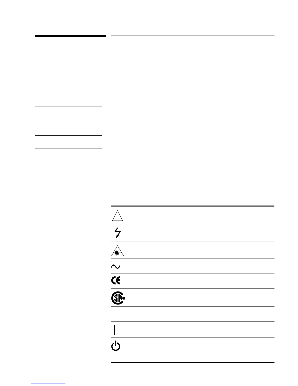
When you see this symbol on your instrument, you should refer to the instrument’s
!
instruction manual for important information.
This symbol indicates hazardous voltages.
The laser radiation symbol is marked on products that have a laser output.
This symbol indicates that the instrument requires alternating current (ac) input.
The CE mark is a registered trademark of the European Community. If it is
accompanied by a year, it indicates the year the design was proven.
The CSA mark is a registered trademark of the Canadian Standards Association.
1SM1-A This text indicates that the instrument is an Industrial Scientific and Medical Group 1
Class A product (CISPER 11, Clause 4).
This symbol indicates that the power line switch is ON.
This symbol indicates that the power line switch is OFF or in STANDBY position.
HP 8511A Test Set Operating and Service Manual
ix
Page 9

Saf et y Earth
Ground
This is a Safety C lass I product (provided with a pr otective earthing
terminal). An uninterruptible safety ea rth groundmust be provided from the
main power source to the product input wiring te rminals, power cor d, or
supplied power cord set. Wheneve r i t is li kely that the pr otection ha s be en
impaired, the product must be ma de i noperative and secured against any
unintended operation.
Bef ore Applyi ng
Power
Verify that the product is configured to match the available main power
source as described in the input power configuration instructions in this
manual. If this product i s to be powered by a utotransformer, make sure the
commont erminal is connected to the neutral (grounded) si de of the ac power
supply.
x
HP 8511A Test Set Operating and Service Manual
Page 10
HP 8511A Test Set Operating and Service Manual
xi
Page 11

Typeface Con ventions
Italics • Used to emphasize important information:
Use this software only with the HP 8511A.
• Used for the title of a publication:
Refer to the HP8511A System-Level User’s Guide.
• Usedt o indicate a variable:
LOAD BIN filename.
Type
Instrument Display • Used to show on-screen prompts and messages that you will see on the
display of an instrument:
The HP8511A will displaythe message
CAL1 SAVED.
[Keycap]
{Softkey}
User Entry • Used to indicate text that you will enter using the computer keyboard;
• Used for labe led keys on the front panel of an instrument or on a
computer keyboard:
[Return]
Press
.
• Used for simulated keys that appear on an instrumentdisplay:
{Prior Menu}
Press
text shown in this typeface must be typed exactly as printed:
LOAD PARMFILE
Type
.
• Used for examples of programming code:
#endif // ifndef NO_CLASS
Path Name
Computer Display
• Used for a subdirectory name or file path:
Edit the file
usr/local/bin/sample.txt
• Usedt o s how messages, prompts, and window labels that appear on a
computer monitor:
Edit Parameters
The
window will appear on the screen.
• Used for menus, lists, dialog boxes, and button boxes on a computer
monitor from which you make selections using the mouse or keyboard:
EXIT
Double-click
to quit the program.
xii
HP 8511A Test Set Operating and Service Manual
Page 12

Contents
1. General Information
Introduction ............................................1-1
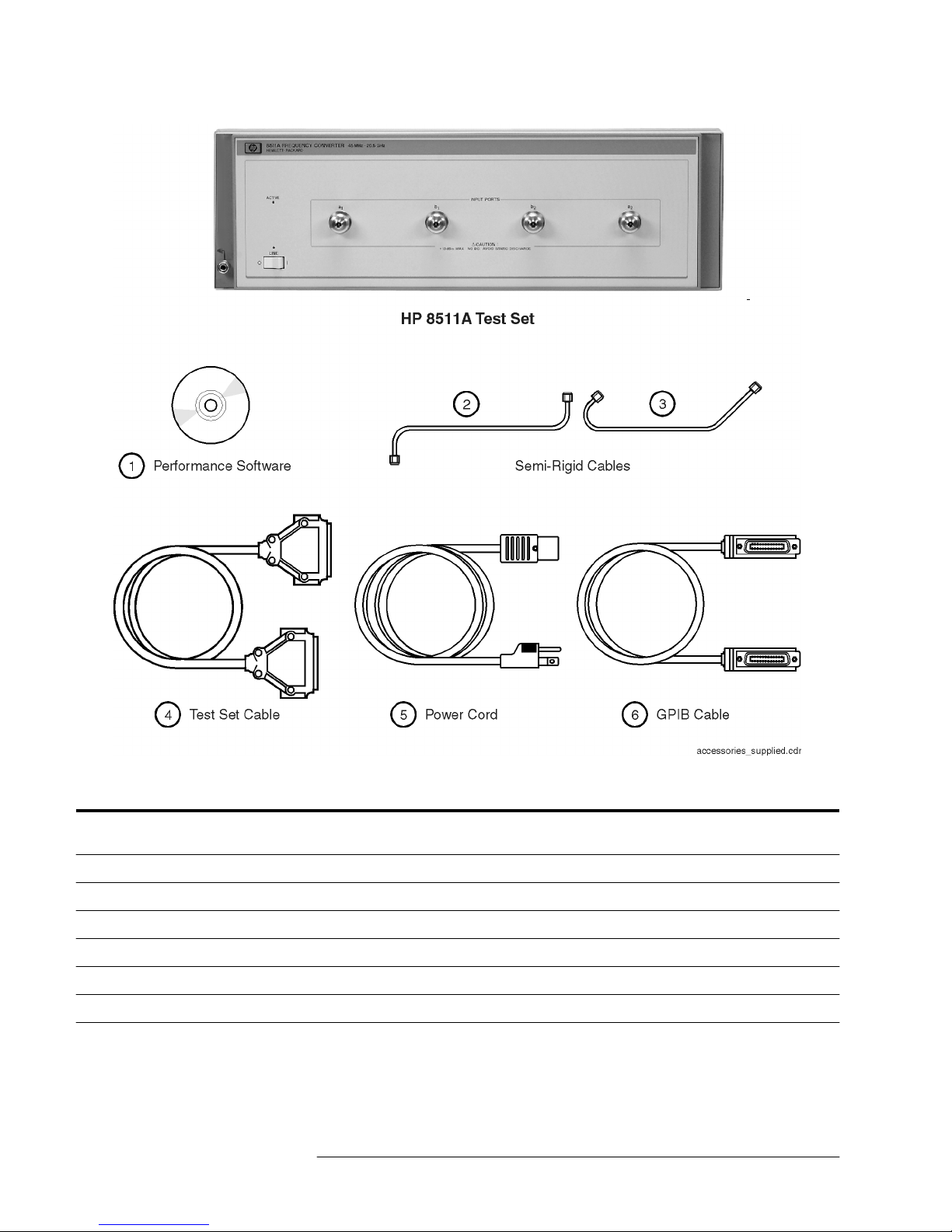
Figure 1-1. HP 8511A Test Se t with A ccessories Supplied ........1-2
Verifying the HP 8511A ......................................1-3
DescriptionandOperatingCharacteristics ........................1-4
Figure 1-2. Example of an HP 8511A Meas urement Set-up .......1-5
SoftwareandHardwareRequirements ...........................1-7
ComputerRequirements...................................1-7
Options ...................................................1-8
Option001 .............................................1-8
Option908 .............................................1-8
Option910 .............................................1-8
Option913 .............................................1-8
Service and Support Opti ons ..................................1-9
OptionW03 ............................................1-9
OptionW30 ............................................1-9
OptionW31 ............................................1-9
Option1BN ............................................1-9
Option1BP.............................................1-9
Accessories ...............................................1-10
Accessories Supplied ....................................1-10
AccessoriesAvailable....................................1-10
Cables................................................1-10
OperatingandSafetyPrecautions..............................1-11
ElectrostaticDischarge(ESD) .............................1-11
Service ...............................................1-11
AdditionalEquipmentRequired............................1-11
Miscellaneous .............................................1-12
Adjustments ...........................................1-12
Replacement Parts ......................................1-12
2. Specifications
Definitions ................................................2-1
Table 2- 1. HP 8510/HP 8511A Performance ..................2-1
Figure 2-1. Conversion Example ............................2-2
Table 2- 2. HP 8510/HP 8511A Characteristics ................2-2
Table 2- 3. HP 8510/HP 8511A Characteristics (part 2) ..........2-3
DynamicAccuracy.......................................2-3
Figure 2-2. Worst Case Dynamic Accuracy (Magnitude) .........2-3
Figure 2-3. Worst Case Dynamic Accuracy (Phase) .............2-3
SourceofSystemDynamicAccuracyErrors...................2-4
HP 8511A Test Set Opera ting and Service Man ual
Contents -i
Page 13

Table 2-4. IF Amplif ier Gain Accuracy ...................... 2-4
Table 2-5. HP 8511A Power Requirements and P hysical
Characteristics ...................................... 2-4
SpecificationAssumptions ................................... 2-5
RecommendedTestEquipment............................. 2-6
Table 2-6. Recommended Test Equipment .................... 2-6
3. Installation
Introduction ............................................ 3-1
Initial Inspection ........................................ 3-1
Table 3-1. Contents of the HP 8511A Shipping Containe r ....... 3-1
EnvironmentalConsiderations ................................ 3-2
OperationandStorage.................................... 3-2
PreparationforUse ...................................... 3-2
Static-freeWorkstation ................................... 3-2
F igur e 3-1. Static Safe Work Area .......................... 3-2
F igur e 3-2. Attaching the R ack Mounting Hardware ............ 3-3
ConnectingtheTestSet...................................... 3-4
MatingConnectors ...................................... 3-4
PowerandControlConnections ............................ 3-4
SignalPathConnections .................................. 3-4
F igur e 3-3. HP 8511A System Connections ................... 3-5
Packaging................................................. 3-6
4. Operation
Introduction ............................................... 4-1
FrontPanelFeatures ..................................... 4-1
F igur e 4-1. FrontPanel Feature s ........................... 4-1
F igur e 4-2. Rear Panel F eatur e s ........................... 4-2
OperatorsCheck ........................................... 4-3
Equipment............................................. 4-3
Table 4-1. Necessary Equipment ........................... 4-3
Procedure ............................................. 4-3
F igur e 4-3. Hardware Configuration for Operator’s Check ...... 4-4
F igur e 4-4. Typi cal Operator’s Chec k CRT Trac e .............. 4-4
Controlling Multiple Test Sets ................................ 4-6
F igur e 4-5. RF and IF Switching with Tw o T es t Sets ............ 4-7
Table 4-2. HP 33311C Coaxial Switch Positions with Two
Test Sets ........................................... 4-7
Installation ................................................ 4-8
Operation ................................................. 4-9
Initialization at Power-up ................................. 4-9
SelectingaTestSet ...................................... 4-9
F igur e 4-6. RF and IF Switching with F our Test Sets .......... 4-10
Table 4-3. HP 33311C Coaxial Switch Positions with Four
Test Sets .......................................... 4-10
Contents-ii
HP 8511A Test Set Operating and Service Manual
Page 14

MeasurementCalibration .................................4-11
OperationalChecks .....................................4-12
PerformanceVerification .................................4-12
5. P erf o rmance Tests
PortReturnLoss ............................................5-2
TestProcedure(optional) ..................................5-2
6. Service and Replaceable Parts
Repl aceable P ar t s ...........................................6-2
Introduction ............................................6-2
ExchangeAssembliesAvailable.............................6-2
Repl aceable P arts List ....................................6-2
ReferenceDesignations ...................................6-2
Table 6-1. HP 8511A Replace able Parts ......................6-3
Repl acem ent P r o ced ures ......................................6-6
Replacingthe(T1)PowerTransformer .......................6-6
Procedure ..............................................6-6
F igur e 6-1. WireConnections to Line ModuleFL1 ..............6-7
Replacingthe(B1)Fan....................................6-8
Procedure ..............................................6-8
ReplacingtheFrequencyConverter ..........................6-9
Procedure ..............................................6-9
F igur e 6-2. HP 8511A Major Assemblies ....................6-10
F igur e 6-3. HP 8511A Miscellaneous Mechanical, Chassis and
Elect rical Parts .....................................6-11
Table 6-2. HP 8511A Option 001 Replaceable P arts ...........6-12
F igur e 6-4. Part s Unique to HP 8511A Option 001 ............6-13
F igur e 6-5. HP 8511A Motherboar d ........................6-14
F igur e 6-6. T est Sets Interconnect Table (1 of 2) ...............6-15
F igur e 6-7. T est Sets Interconnect Table (2 of 2) ...............6-17
HP 8511A Test Set Operating and Service Manual
Contents-iii
Page 15

-iv
HP 8511A Test Set Operating and Service Manual
Page 16

1
General Information
Introduction The HP 8511A four channel frequency converter test set is an integral
component of the HP 8510 measurement system. The HP 8511A
documentation is to be used with the HP 8510 documentation, and may be
inserted into the HP 8510 test accessories binder provided with your
HP 8510 manual set.
The HP 8511A Operating portion consists of:
• General Information
• Installation
• Operation
• Performance Tests
The HP 8511A Service portion consists of:
• Replaceable parts
• Service information
HP 8511A Test Set Opera ting and Service Man ual
1-1
Page 17
General Informat ion
Figu re 1- 1 HP 8511A Test Set with Accessories Supplied
Reference
Designator
1 08511-60024 2 HP 8511 A ,B and A ntenna Meas urement Syst em Per formanc e Verifica tion Softwar e As sembly
2 08510-20006 1 Semi -rigi d cable
3 08510-20005 1 Semi -rigi d cable
4 08510-60102 1 Test set cable assembly
5 8120-1348 1 Power cord (USA only)
6 8120-3445 1 GPIB ca bl e
HP Par t Num b er Qty Descripti o n
1-2
HP 8511A Test Set Opera ting and Service Man ual
Page 18

General Infor mati on
Verifying the HP 8511A
Verifying the HP 8511A
The HP 8511A has been designed to operate specifically with the HP 8510
network analyzer .
• To install the instrument, turn to Chapter 3, “Installation” of this
manual.
• To check the proper operation of the HP 8511A, see “Operators Check”
on page 4-3 of this manual.
• To verify that the instrument meets its published specifications, use the
HP 8511A,B and Antenna Measurement System Performance
Verification Software (HP part number 08511-60024).
• To troubleshoot the HP 8511A, begin with the “Service and Equipment
Overview” chapter of the HP 8510 On-Site Service Manual.
HP 8511A Test Set Opera ting and Service Man ual
1-3
Page 19

General Informat ion
Description and Operating Characteristics
Description and Operating Characteristics
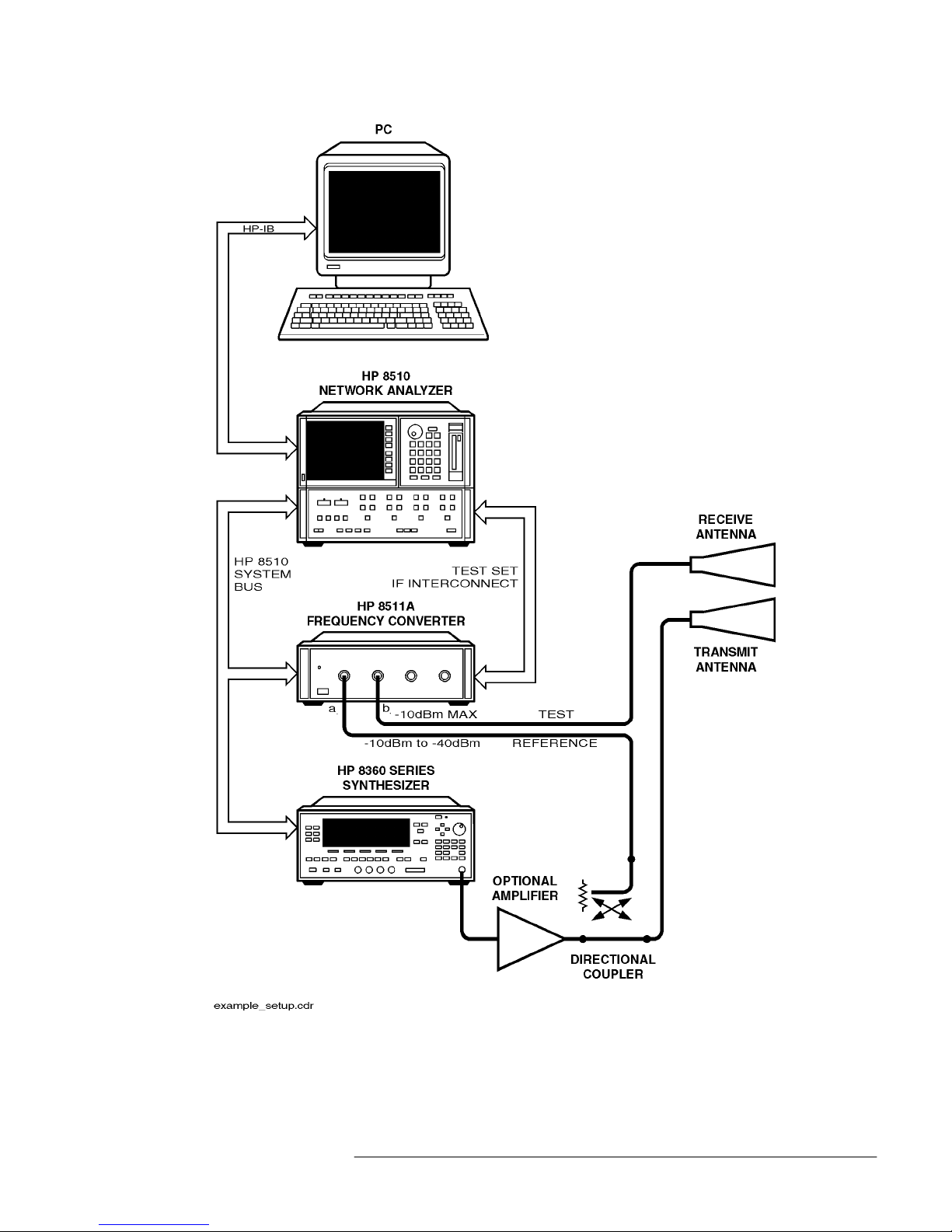
The HP 8511A four channel frequency conve rter test set, has been designed
to operate with the HP 8510 network analyzer a nd other microwave
accessories (like c ouplers and power splitters). The HP 8511A provides a
conv enient means of customizing a test configuration for a variety of
applications within the frequency range of 45 MHz to 26.5 GHz. In addition
to configurations for measuring reflection and transmission parameters of
one-port or two-port devices, youcan build configurations to characterize
antenna parameters, radar c ross sections and fr equenc y translation devices.
Figure 1-2 on page 1-5 shows one possible measurement set-up.
1-4
HP 8511A Test Set Opera ting and Service Man ual
Page 20
General Infor mati on
Description and Operating Characteristics
F igure 1-2 Example of an HP 8511A Measurement Set-up
HP 8511A Test Set Opera ting and Service Man ual
1-5
Page 21

General Informat ion
Description and Operating Characteristics
Table 2-1 on pa ge 2-1 lists the operating specificationsand characteristics of
the HP 8511A. N ote that the performance of theHP 8511A is v eri fiable only
as part of an HP 8510 system. Verification is performed at the ports of the
HP 8511A.
1-6
HP 8511A Test Set Opera ting and Service Man ual
Page 22

Software and Hardware Requirements
Software and Hardware Requirements
General Infor mati on
Computer
Requirements
The computer requirements to successfully install and operate the software
are as follows:
• 100% IBM-PC compatible computer.
• Pentium 133 or better.
• Windows 95
, Windows 98or Windows NT 4.0 installed.
• GPIBinterfacecard and cable, or Hewlett-Packard GPIBcard and cable.
• HP BASIC for Windows, version 6.32 or later installed.
• ACD-ROMdrive.
• HP 8511A,B and Antenna Measurement System Performance
Verification Software.
• Internet Explorer
43.0 or higher or Netscape4.0 or higher.
HP 8511A Test Set Opera ting and Service Man ual
1-7
Page 23

General Informat ion
Options
Options
Option 001 Option 001 adds IF switching capability to allow u p t o four test s et s to be
connected to the HP 8510 at the same time. The tes t se t in use is selected
from the HP 8510 f ront panel. The 20 M Hz IF s ignal is transmitted from the
standard test sets thr ough the option 001 test set to the HP 8510. IF
switching is performed automatically by the option 001 test set, without
reconnections.
Option 908 Option 908 supplies the test set with the parts required to rack mount it with
the handles removed. Refer to Chapter 3, “Installation” of this manual for
additional information.
Option 910 Provides a duplicate tes t set manual a t the time of purchase.
Option 913 Option 913 supplies the test set with the parts required to rack mount it with
handles. Refer to Chapter 3, “Installation” of t his manual for a dditional
informati o n .
1-8
HP 8511A Test Set Opera ting and Service Man ual
Page 24

Servic e and Support Options
Option W03 Warranty Conversion
Option W03 converts the standard one year retur n to Hewlett-Packard
warranty to a 90 day on-site warra nty. W03 can only be order ed at the time
of instrument purchase. Instruments ordered with option WOS are identified
on the serial number la be l, or on a special iden tifica tion la be l s u pplie d w ith
the instrume nt.
Option W30 Extended Service (R eturn)
Option W30 adds two additional years of r eturn-to-HP service, to follow the
first year of warranty. Option W30 can be ordered only atthetimeofsale.
Instruments ordered with option W30 are identified on the serial number
label, or on a special identification label supplied witht he instrument.
General Infor mati on
Service and Support Options
Option W31 Extended Service(On-Site)
Option W30 adds two a dditi onal ye ars of on-site repair coverage, to follow
the first year of warranty. Option W31 can be ordered only at the time of
sale.
Option 1BN Certificate of C alibration
Option 1BN adds MIL-STD 45662A C ertificate of Calibration to t he
instrument. This option must be ordered when the i nstrument is ordered.
Option 1BP Certificate of C alibration (Wi th Data)
Option 1BP adds a MIL-STD 45662A certificate of C alibration and the
corresponding calibration data to the instrument. This option must be
ordered when the instrument is or dere d.
NOTE
Additional system warranty inf ormation is included inthe
HP 8510 manual set.
HP 8511A Test Set Opera ting and Service Man ual
1-9
Page 25

General Informat ion
Accessor ies
Accessor ies
Accessories Supplied Figure 1-1 on page 1-2 refers to the HP 8511A with the accessories and part
numbers supplied.
Accessories Available The HP 8511A c an s upport a multitude of m easureme nt systems . The
calibration, verification and adapt er kits listed below may or may not be
applicable for any given system. Please consult with your local HP Field
Engineer for specific recommendations. Additional information is included
in the H P 8510 manual set and the HP 8510 data sheet.
Connector Type Calibration Kit Verification Kit Adapter Kit
3.5 mm HP 85052B,E HP 85053B
7 mm HP 85050B,C,D HP 85051B
Type-N 50
3.5 to 7 mm HP 85130A,B
Ω
HP 85054B HP 85055A
Cables The choice of cables depends on t he type ofsignal separation device(s) used
and the syst em configuration. A twe nty foot long IF interconnect cable can
be ordered using HP pa rt number 08510-60103.
1-10
HP 8511A Test Set Operating and Service Ma nual
Page 26

Electro s ta tic
Discha rge (ES D)
General Infor mati on
Operating and Safety Precautions
Operating and Safet y Precauti on s
CAUTION
Ground yourself (with a wrist strap) and the instrument, especially when
making or breaking conne ctions at the input ports. Do not exceed the
instrument’s maximum inputpower level of + 13 dB m as +13 dBm is the
damage level.
Other than the above ESD precautions, you ne ed obser ve only normal
precautions in handling and opera ting the HP 8511A.
Serv ice The voltages in this test set warrant normal caution for operator safety.
Service should be per formed onl y by qua lified personnel. Form ore
information on service s trategy, troubleshooting procedures, replaceable
parts an d s imila r information refe r to the H P 8510 On-Site Service Manual.
Additi onal Equ ipment
Required
Table 2-6 on page 2-6 lists additional equipment andaccessories required
for use w ith the HP 8511A f reque ncy converter. The table also note s which
items are required toverif y the pe r formance of the test set and whic h i tems
are required for operation. Other equipment may be substituted if its
specificat ions meet or exceed the specifications listed in the critical
specificat ions column.
HP 8511A Test Set Operating and Service Manual
1-11
Page 27

General Informat ion
Miscella neous
Miscellaneous
Adjust men ts The HP 8511A ha s no a djustments. Specifically, no attempt should be made
to adjus t the samplers.
Replacement Parts The r eplaceable parts are listed in Chapter 6, “Service and Replaceable
Parts” of t h is manual.
1-12
HP 8511A Test Set Operating and Service Ma nual
Page 28

2
Specifications
Definitions
Specifications and characteristics differas defined in Table 2-1. Both are
based on certain operating conditions. Those conditions are defined in
“Specification Assumptions” on page 2-5.
Table 2-1 HP 8510/HP 8511A Performance
Parameter 0.045 to 8 GHz 8 to 20 GHz 20 to 26.5 GHz
1
Frequency Response Tracking
Magnitude (ripple)
Phase (ri pple)
Magnitude slope
4
Crosstalk
High Level Noise
Magnitude (ratio)
Phase (ratio)
Low Level Noise
Conver si on Gain
1. These performance parameters are field verifiable using the supplied software and the performance tests documented in the
Antenna Measurement System Performance Verification Software Installation and Getting Started Guide
2. Deviation from a least-squares-straight-line fit, excluding noise and slope. Ratio measurement of any two ports. (Note: b2 to b1 trac king is n ot field verified
with the performance test software.)
3. Slope of least-squares-straight-line fit over full frequency range.
4. Uncorrected port to port crosstalk with averaging factor of 1024.
5. Trace noise, sweep to sweep variation.
6. Low level noise measured with 50 ohm load at port, and calculated as the mean value of a 101 point trace with IF averaging set at one. Low level
noise varies with averaging factor 10 log (averaging factor).
7. See Figure 2-1 on page 2-2.
2
3
5
6
7
±
0.5 dB
±
5 degrees
±
0.08 dB/G Hz
−
80 dB
0.012 dB r m s
0.1 degrees rms
−
95 dBm
±
0.5 dB
±
5 degrees
±
0.08 dB/G Hz
−
80 dB
0.02 dB rms
0.15 degrees rms
−
90 dBm
+
2 dB to −12 dB
±
0.5 dB
±
5 degrees
±
0.08 dB/G Hz
−
80 dB
0.04 dB rms
0.25 degrees rms
−
85 dBm
HP 8511A,B and
(HP part number 5962-0493).
HP 8511A Test Set Opera ting and Service Man ual
2-1
Page 29

Specificat io ns
Figu re 2- 1 Conversion Example
Table 2- 2 HP 8510/HP 8511A Characteristics
Parameter 0.045 to 8 GHz 8 to 20 GHz 20 to 26.5 GHz
2
Dynamic Range
all inputs
Accuracy Enhanced Crosstalk
−
115 dB
1. The performance parameters listed are characteristic of the HP 8511A/HP 8510. They are typical or nominal figures and are not f ield verifi able.
2. Determined by 0.1 dB compression level and system low level noise. Low level noise measured with 50 ohm load at port and 1024 averaging factor.
Noise floor varies with averaging factor:10 log (averaging factor).
3. Effective crosstalk with isolation calibration, excludes noise.
3
105 dB
(
−
10 to −115 dBm)
−
115 dB
1
105 dB
(−10 to −115 dBm)
−
113 dB
98 dB
(−15 to −113 dBm)
2-2
HP 8511A Test Set Opera ting and Service Man ual
Page 30

Table 2-3 HP 8510/HP 8511A Characteristics1(part 2)
Tracking Drift (typical) Magnitude 0.001 x V °C, Linear
Input Ports
Connector type:
Impedance:
Damage level:
Phase (0.1
female 3.5 mm
50 ohms nominal
+
13 dBm (20 mW) CW RF input2
+
f(GHz)) x V °C, degrees
Specificat ion s
Port input power for phase lock:
1. The performance parameters listed are characteristic of the HP 8511A/HP 8510. They are typical or nominal figures and are not f ield verifi able.
−
2. Do not exceed
5 dBm input to sampler for proper phase lock operation.
Frequency:
0.045 to 8 GHz
8 to 20 GHz
20 to 26.5 GHz
Minimum:
−
35 dBm
−
40 dBm
−
38 dBm
Maximu m:
−
5 dBm
−
5 dBm
−
5 dBm
Dynamic Accuracy Figure 2-2and Figure 2- 3 ill ustrate worst case ma gnitude and phase
uncertaintydue to IF residual s and detector inaccuracies. This data excludes
uncertainty due to noise, f requency response, dir ectivity, port matches and
connector repeatability.
Figu re 2- 2 Worst Case Dynamic A ccuracy (Magnitude)
Figu re 2- 3 Worst Case Dynamic A ccuracy (Phase)
* Phase detector accuracy is bett er than 0.02 degrees, useful for measurements where only phase changes.
*
HP 8511A Test Set Opera ting and Service Man ual
2-3
Page 31

Specificat io ns
Sou rce of Sys tem
Dynamic Accuracy
Errors
Table 2- 4 IF Amplifier Gain Ac curacy
The factors affecting dynamic accuracy listed below are primarily a function
of the IF detector. C ompr ession through, is primarily a function oft he
sampler/mixer circuitry. In order to mea sure the se values, some of the
system cables must be dis connected to gain access to the individual
instrume nts.
IF Amplifier Power Range
−
10 to −34 dBm 0
−
34 to −46 dB
−
46 to −58 dB
−
58 to −70 dB
≤
70
Detector Circularity Error
IF Residuals
IF Linearity
1
Maximum Gain Error (dB)
±
0.005
±
0.010
±
0.015
±
0.025
±
0.003 dB peak
140 dBm
0.003 dB
1
−
±
±
Incremental Phase Accuracy
(Phase versus Phase)
at Measurement Reference
1. Measured at the IF input to the HP 8510, not at the test set test ports.
0.001 degrees/degree, not to exceed 0.02
degrees peak.
Table 2- 5 HP 8511A Power Requirements and Physical C haracteristics
Operat ing Temperature 0 °C to 55 °C
±
Power 110, 120, 220 or 240
Dimensions 460 mm x 133 mm x 609 mm (18.1 x 5.25 x 24 inches)
Weight 13 kg (29 lb) net; 17 kg (38 lb) shipping
10% Vac; 47 to 66 Hz line frequency
2-4
HP 8511A Test Set Opera ting and Service Man ual
Page 32

Specificat ion s
Spec ificat ion Assum p tion s
Specific ation Assumptions
The specifications of the HP 8511A assume that the f ollowing operating
conditions are met:
• All s ystem instruments have reached stable operatingtemperature.
• RF source: HP 8360 series source. Other sources recommended in the
HP 8511A Performance Test procedures may be used for verification
within the frequency limits of those sources. When used with another
recommended source, the performance specifications may differ from
those for the HP 8510, HP 8511A, HP 8360 series configuration. The
performance test softwarewill display and print the limits for the chosen
configuration.
• Performance verification temperature: 23 ±3 ° C.
• RF source power levels as follows:
Test
Compression, Crosstalk
Conversion Gain, Tracking, High Level Noise
Power at Input Level (dBm)
0.045 to 18 GHz 18 to 26.5 GHz
−
10
−
15
−
15
−
20
HP 8511A Test Set Opera ting and Service Man ual
2-5
Page 33

Recommended T est
Equipment
Table 2-6 RecommendedTe st Eq u ipment
Specificat io ns
Specification Assumptions
Item Critical Specifications
Network analyzer no substitute HP 8510B, C
PC no substitute See “Computer
Disk drive compatible with controller
Multimeter range: 0 to 50V H P 3456A
Oscilloscope 50 MHz bandwidth HP 1740A
Power Meter HP 436 Option 022
Power sensor dc to 26.5 GHz (APC 3.5) HP 8485A
Power splitter dc to 26.5 GHz (APC 3.5) HP 11667B (5086-7408)
Female to female adapter dc to 26.5 GHz (APC 3.5) 1250-1749
Male to male adapter dc to 26.5 GHz (APC 3.5) 1250-1748
Recommended Model
(or Part Number)
Requirements” on
page 1-7 for detailed
information.
HP 437
HP 438
HP E4418
HP E4419
50 ohm load (male connector) dc to 26.5 GHz (APC 3.5) HP 909D option 040
Torque wrench, 8 in-lb, 5/16 in 8710-1765
RF cable, 1 m RF source to splitter 26.5 GH or 50 GHz (as needed)
Use good quality flex or
semirigid cable.
Attenuator, 6 dB (qty 2) dc to 26.5 GHz (APC 3.5) HP 8493C option 006
Attenuator, 10 dB dc to 26.5 GHz (APC 3.5) HP 8493C option 010
RF cable 1 M APC 3.5
RF cable 10 in (qty 2) APC 3.5
2-6
HP 8511A Test Set Opera ting and Service Man ual
Page 34

3
Installation
Introduction This chapter explains how to install the HP 8511A test set. The topics
covered include initial inspection, environmental considerations, positioning
and connecting the test set for use, and packaging the instrument. Refer to
the “Installation” chapter of the HP 8510 On-Site Service manual for more
complete system connection and turn-on instructions.
Initial Inspection Inspect the shipping container (including cushioning material) for damage.
If it is damaged, keep it until you have checked the contents for
completeness. The contents are listed in Table 3-1.
In addition,check the test setmechanicallyand electrically. If thetestset and
shipping container are undamaged, passing the Operator’s Check (in
Chapter 4, “Operation”) should suffice for incoming inspection. If the test
set does not pass the Operator’s Check, refer to the troubleshooting
procedures in the HP 8510 On-Site Service Manual or call your local HP
Customer Engineer.
If the shipping container is damaged or defective, keep the shipping
materials and notify both the carrier and the nearest Hewlett-Packar d office.
The HP office will arrange for repair orreplacement of the test set without
waiting for settlement of the claim. If the components receivedwith the test
set are incomplete, notify your nearest HP office and the deficient parts will
be sent to you.
Table 3-1 Contents of the HP 8511A Shipping Container
Item Part Number
Power Cord 8120-1 348
Tes t set cable assembly 08510- 60102
GPIB cable 8120-3445
Performance test software (CD-ROM) assembly 08511-60024
HP 8511A Operating and Service Manual
Semi-rigid cables (2)
1. For performance testing and operator’s check.
1
08511-90072
08510-20005
08510-20006
HP 8511A Test Set Opera ting and Service Man ual
3-1
Page 35

Installation
Environmental Considerations
Environmental Considerations
Operationand Storage To perform within specifications, the HP 8511A should be operated in
temperatures between 0 °Cand+55°C with relative humidity between 5%
and 95% at 40 °C (maximum dry bulb temperature). It may be operated at
altitudes up to 4,500 metres (15,000 feet).
The HP 8511A may be stored in temperatures from
relative humidity up to 90% at +65 °C (maximum dr y bulb temperature) and
at altitudes up to 15,240 metres (50,000 feet).
Preparation for Use P ositioning the Test Set
Typically the HP 8511A is placed under the HP 8510 network analyzer or
the source whether it is rack-mounted or used on a bench. To install the
flanges to rack mount the instrument (with or without handles) ina standard
19 inch rack, refer to Figure 3-2 on page 3-3.
Static-free
Workstation
When installing the test set for use on a bench, place it on a grounded
anti-static work surface to lessen the chance of ESD damage. The anti-static
surface should extend far enough in front of the test set to provide effective
protection at the test ports and cable ends. If your test set is equipped with a
grounding receptacle, you may use that in place of a static mat.
− 40 °Cto+75°C, with
Figure 3-1 Static Safe Work Area
3-2
HP 8511A Test Set Opera ting and Service Man ual
Page 36

Installation
Environmental Considerations
F igure 3-2 Attach ing the Rack Mounting Hardware
The recommended system rack is the HP 85043C. I nstructions for
rack-mounting the HP 851 1A in a system configuration with the H P 8510
are provided in the “Installation” section of the HP 8510 On-Site Service
Manual and in the HP 85043C System Rack Installation Manual (HP part
number 85043-90022).
HP 8511A Test Set Opera ting and Service Man ual
3-3
Page 37

Installation
Connecting the Test Set
Connecting the Test Set
Mating Connectors IN PUT PORTS al, bl, b2 anda2 are precision 3.5 mmfemale connectors
and mate with precision 3.5 mm male connectors.
The TEST SET INTERCONNECT c onnector is a series D subminiature
female conne ctor with 7 RF cavities. It mates w ith t he corresponding male
connector.
The 8510 SY ST EM BUS connector is a f emale GPIB type c onnector and
mates with the corr esponding male connectors of GPIB cables.
Power and Control
Connections
Signal Path
Connections
The following connections, with the exception of line power, a re il lustrated
in F igure 3- 3 on page 3-5. That figure also shows connections r equired for
the RF source.
1. Connect the line cord between an electrical outlet and the line module to
supply power to the frequency converter.
2. Connect the test set IF interconnect cable from the J11 TEST SET
INTERCONNECT connector on the rear pa nel of the HP 8511A t o the
J1 TESTSET INTERCONNECT connector on t he rear pane l ofthe
HP 85102 IF detector.
3. Connect the system bus cable from the HP 8511A J12 HP 8510
SYSTEM BUS connector to the HP 8510 INTERCONNECT
connector of the HP 85101 display/processor. The test set IF
interconnect cable and the s ystem bus cable transmit control signals
between the test set and the network analyzer.
The IF signa ls fr om the test set ar e transm itted to the HP 85102 1F detector
by the test s et IF interconnect cable supplied. Longer IF interconnect cables
are available (see “Cables” on page 1-10) of this manual.
RF signa ls are typically tran smitted from the s ource to the DU T (device
under test) or s ignal se paration devices by 3. 5 mm flexible or semi-rigid
cables.
3-4
HP 8511A Test Set Opera ting and Service Man ual
Page 38

Installation
Connecting the Test Set
F igure 3-3 HP 8511A System Connections
HP 8511A Test Set Opera ting and Service Man ual
3-5
Page 39

Installation
Packaging
Packaging
If reshipping is r equired,each test set should be repackaged in the original
factory package. Containers and materials identical to those used by the
factory are available through Hewlett-Packard offices.
If comparable packagingmaterialsare used, wrap the test setin heavy paper
or anti -static material. If shipping to an HP Office or Service Ce nter,
complet e and attach a service tag ( refer to the “I nstallation”chapter in the
HP 8510 On-Site Service Manual). Us e s ufficient shock absorbing m aterial
on all sides of the HP 85llA to provide a thick, firm cus hion and t o prevent
movement. Seat the shipping container securely and mark it FRAGILE.
In any correspondence with HP, refer to the HP 8511A by full model and
serial number (located on the rear panel).
3-6
HP 8511A Test Set Opera ting and Service Man ual
Page 40

4
Operation
Introduction
Thischapterillustratesthefeatures and functions of the front and rear panels
of the HP 8511A (see Figure 4-1 and Figure 4-2 on page 4-2).
CAUTION
Front Panel Features
Static Sensitive. Handle only at a static safe w ork station. Damage level of
input ports: > +13 dBm (20 mW) or > 1.0 Vdc.
Figure 4-1 Front Panel Features
1. Line Switch. This switch turns the test set on and off. When the side of
the switch labeled O is depressed, the test set is off; l is on.
2. Line LED. This LED goes on and off with the test set.
3. Active LED. This LED lights about two seconds after power is turned
on, following the successful conclusion of self-test.
4. Input Ports a1, b1, b2, a2. These input ports transmit RF energy to the
samplers within the instrument.
HP 8511A Test Set Opera ting and Service Man ual
4-1
Page 41

Operation
NOTE
The a1 or a2 input port must be used for system phaselock.
Figu re 4- 2 Rear Panel Fe atures
5. Li ne module. This assembly house s the line cor d c onnector, line fuse
and line voltage selector. Pull out the ri ght side of t he line module c over
to replace or change the fuse, or to c hange the voltage selection. Note
that the voltage selector drum must be removed to rotate itt o a different
setting. Recommended fuse va lues a re pri nted on the rear panel.
6. J10 Test Set Interconnect. This connector is used only in test sets with
Option 001. It allows connecting a second tes t set toan HP 8510 s ys tem
and automatically selecting the IF output from either t est set f or
processing by the HP8510.
7. J11 Test Set Interconnect. This connector transmits the IF signal from
the test set tothe HP 85102 IF Detector. I t a lso transmits control signals
bidirectionally.
8. HP 8510 Sys tem Bus Address Switch. Thi s five-gang bi nary-weighted
switch selects the system bus address of the test set. T he binaryweight
of each pole is indi cated on the rear panel as are the on and off positions.
Decimal twenty (off-off-on-off-on, from left to right) is the default
setting.
9. J12 HP 8510 System Bus Connector. This c onnector is used for GPIB
communications with the HP 85101 display/processor.
4-2
HP 8511A Test Set Opera ting and Service Man ual
Page 42

Equipment
Operators Check
The purpose of this check is to confirm that the H P 8511A f requency
conve rter functions properly as part ofan HP 8510 system. See Chapter 5,
“Performance Tests” for m ore inf ormation.
Table 4-1 Ne cessary Equipment
Description Model or HP Part Number
Network analyzer system HP 8510B,C
Semi-rigid cables (2) 08510-20005
Power splitter HP 11667B (5086-7408)
Operation
Operators Check
08510-20006
1
20 dB pad (attenuator) HP 8493C option 020
1. Supplied with the HP 8510 service kit.
NOTE
This procedure must be pe rformed with a properly configured and
operational HP 8510 s ystem. See Figure 3-3 on page 3- 5 or the
“Installation” chapter of the HP 8510 On-Sit e Se rvice Manual for more
informati o n .
Procedure Plug in and tur n on the frequency converter. The line LED should light
immediately and the active LED should light in about two s econds. Those
indications mean that the instrument has passed its self-test. In case of
difficulty, refer to the ‘Main Troubleshooting Procedure” chapter in the n the
HP 8510 On-Site Service Manual or c ontact your local HP Service Office.
Turn on t he source and then the HP 8510.
1. Press
[PRESET]
HP 8360 series s ystems:
Press STIMULUS
sweep time to 200 ms. In narrow band systems, the power level in
the frequency band generated should match the level shown in
Figure 4-4 on page 4-4 for a given frequency.
on the HP85102 to preset the HP 8510.
[MENU] [ST EP]
and then use the entry keys to set the
HP 8511A Test Set Opera ting and Service Man ual
4-3
Page 43

Operation
Operators Check
NOTE
All of the observed tracesshould de crease from −15 ±5dBat45MHzto−35
±5 dB at 26.5 MHz, similar to Figure 4-4.
a1 and b1 Test
2. Loosely connect the 20 dB pad to the power splitter and the RF source
cable to the pad as shown in Figure 4-3 on page 4-4. Connect the other
end of the RF source cable to the output of the source. Rotate the
semi-rigid cables to the required position for connection to ports a1 and
b1. Tighten all connections.
Figure 4-3 Hardware Configuration for Operator’s Check
3. Press PARAMETER
[MENU] [User 1 a1]
to observe the a1 powerlevel trace.
Figure 4-4 Typical Operator’s Check CRT Trace
4. Press
[User 4 b1]
to observe the b1 power level trace.
4-4
HP 8511A Test Set Opera ting and Service Man ual
Page 44

Operators Check
a2 and b2 Test
5. Reconnect the s emi-rigid ca bles (as in step 2) to ports a2 and b2.
Disregard the running error messa ge
Caution: “NO IF FOUND”
.
Operation
6. Press
[Us er 3 a2] [REDEFINE PARAMETER] [PHAS E L OCK] [a2] [REDEFINE DONE]
observe the a2 power level trace.
7. Press
[Us er 2 b2] [REDEFINE PARAMETER] [PHASE LOCK] [a2] [REDEFINE DONE]
see the b2 trace.
8. If any of the tracesare not within the li mits notedin this procedure,
check all of the connections and repeat the procedure. If symptoms
persist, refer to the “Service and Equipment Overview” chapter in the
HP 8510 On-Site Se rvice Manual.
to
to
HP 8511A Test Set Opera ting and Service Man ual
4-5
Page 45

Operation
Controlling Multiple Test Sets
Controlling Multiple Test Sets
Option 001 for the HP 851X-series test sets allows an HP 8510 to alternately
control up to four test sets. While a measurement is proceeding on test set
number 1, which is equipped with option 001, test device hookup can be
accomplished on Test Set number 2,which does not need to be equipped
with option 001, unless another test set is to be connected. When the
measurement on test set number 1 is complete, then the HP 8510 can control
test set number 2.
In a s tandard test set, the 20 MHz IF and control signals are applied directly
to J11 TEST SET INTERCONNECT, which connects to the HP 8510.
Option 001 adds a set of IF switches, control swit ches, and the JIO TEST
SET INTERCONNECT connector. This allows the selectionof 20 MHz test
set IF signals. As shown in Figure 4-5 on page 4-7, test set number l can
apply its IF to the HP 8510 or it can switch to pass the IF from test set
number 2 through the J10 TEST SET INTERCONNECT to the HP 8510.
4-6
HP 8511A Test Set Opera ting and Service Man ual
Page 46

Operation
Controlling Multiple Test Sets
F igure 4-5 RF and IF Switching with Two Test Sets
Table 4-2 HP 33311C Coaxial Switch Positions with Two Test Sets
New ADDRESS of Test Set Test Set Selected HP 33311C Coaxial Switch Port Selected
20 1 Port 1
21 2 Port 2
HP 8511A Test Set Opera ting and Service Man ual
4-7
Page 47

Operation
Installation
Inst al l a tio n
Set each test set rear panel address switch to the address li sted i n Tabl e 4-2
on page 4-7 i f using a two te st set configuration, and Table 4-3 on page 4- 10
if configurin g mor e than two t est s ets. Use the s upplie d te s t s et inte r connec t
cable to connect test s et number 1, J11 to the H P 8510. Use the s upplied test
set interconnect cable to connect test set number 2,J11, t o test set number 1,
J10. You ma y continue this test set “ daisy chain” to include up to four test
sets if the t otal le ngth of all test set interconnect cables does not e xceed 13
meters (about 40 feet). T he last test set in the chain does not requir e option
001.
If the R F coaxial switch (s) is not incorpor a ted into the sys tem, then the RF
input to the tes t s et must be manually switched to the active test set.
4-8
HP 8511A Test Set Opera ting and Service Man ual
Page 48

Operation
Operation
Oper ation
Initialization at
Power-up
Upon power-up, the IF switches must be configured so t hat only one system
test set is active. The following procedure shows how to make one te st s et
active.
1. Check th e active lights of all syst em te st sets.
2. Check the HP 8510’s expected test set address by pres sing
SET]
. This should match the address of the desired tes tset. If not, change
the address.
3. If unselected test setsare active, (active light ON), deactivate the test set
by temporarily addressing it. Then return to the desired address.
[LOCAL] [TEST
Selecting a Test Set TestSet IF Switching. The activetest set is selectedby the built-in
capability of the HP 8510 to generate an addressed command to the test set.
Each time the HP 8510 ADDRESS of TEST SET function is changed (see
HP 8510 LOCAL Menu), the HP 8510 switches the pr eviously addressed
test set IF to external and the newly addressed test set IF to internal. The test
set front panel ACTIVE indicatorshows the test set status. When the test set
is activethe IF signals from the test set are applied directly to J11 TEST SET
INTER CONNE CT. When the test set is inactive the IF signals appearing at
J10 are passed through to J 11and on to the next test set or the HP 8510.
The address of the test set can be changed manually from the HP8510 front
panel by selecting the ADDRESS of TEST SET function then e nt ering the
[XI],
address of the test set and pressing
control using the HP 8510 GPIB ADDRESS; command. The GPIB address
of a particular test s etis set by a ddre ss switches on the test set rear panel.
RF Switch Driver Commands. A related feature of the HP 8510 is that
when the HP 8510 ADDRESS of TEST SET function is changed, a code
sequence is automatically issued over the HP 8510 system bus to the de vice
at the ADDRESS of RF SWITCH. In the recommended configuration, this
device is an HP 11713A attenuator/switch driver which in turn controls one
or more HP 33311C coaxial switch. As shown in Figure 4-5 on page 4-7 and
Figure 4-6 on page 4-10, these switches are used to select which of the test
sets receive the RF Output of the network analyzer s ource. The exact
command issued depends upon the new value of the ADDRESS of TEST
SET function, also shown in Figur e 4-5 on page 4-7 and Figure 4-6 on
page 4-10.
or it can be changed under program
HP 8511A Test Set Opera ting and Service Man ual
4-9
Page 49

Operation
Operation
Figu re 4 - 6 RF and IF Switching with Four Test Sets
Table 4- 3 HP 33311C Coaxial Switch Positions with Four Te st Sets
Ne w ADDRESS of Test Set Test Set Selected
20 1 Port 1 Port 1
21 2 Port 1 Port 2
22 3 Port 2 Port 1
23 4 Port 2 Port 2
4-10
HP 33311C Coaxial Switch Port Selected
Switch #1 Switch #2
HP 8511A Test Set Operating and Service Ma nual
Page 50

Operation
Operation
Measurement
Calib r ation
After selecting the active test set, perform the system calibration procedure
as usual.When you select a dif f erent test set , make sure that you recallthe
cal set thatapplies to that tes t set .
Since the cal set limited instrument s tate does not include the number of the
act i vetest set, a cal set which does not applyto the current tes t set can be
turned on without any HP 8510 caution messages appearing. This w ill cause
errors inthe displayed data because incorrect errorcoefficients are applied to
the measured data.
It may be conve nient to store a hardwa re state file and an instrument state
file for each combination of test set and cal set. Y ou may also store your
hardware sate file on a disk for future us e. T o change the configuration,
simply recall the appropriate hard ware stat efile, which sets the address of
test set and issues the RF switch command, then the appropriate instrument
stat e f ile, whi ch recalls th e cal set.
HP 8511A Test Set Operating and Service Manual
4-11
Page 51

Operation
Operation
Operational Checks To check operation of a multi ple te st set configuration:
1. Connect a device with a known response at tes t s et number 1.
Perfor m ance
Verification
2. Press HP 8510
[LOCAL] [TEST SET], [ADDRESS of T EST SET].
3. Enter the address of test set number 1(this would be 20).
4. Press
5. Press
[xl].
The test set number 1 measurement should appear.
[DISPLAY] (D ATA-MEMORY] [DISPLA Y: DATA and MEMORY]
to store the trace
for latercomparison.
6. Use ADDRESSof TEST SET to select test set number 2.
7. Switch back to test set number 1.
8. Observe any difference in the response between the stored trace and the
result after switching back and forth between the test sets. Repeat for
each of the test sets. Any difference in the data believed due to the
option 001 IF s witch or RF switching must be investigated.
Standard system performance verification procedures are used to verify the
operation of the option 001 test set as test set number 1. To ve rifythe
performance of another test set in the chain, select it as the active test set and
proceed as usual.
4-12
HP 8511A Test Set Operating and Service Ma nual
Page 52

5
Performance Tests
The HP 8511A ships with the HP 8511A/B and Antenna Measurement
System Performance Verification Software assembly (HP part number
08511-60024). This assembly includes performance verification software
with on-line help and an installation and getting started manual (HP part
number 5962-0493).
Follow the HP 8511A/B and Antenna Measurement System Performance
Verification Software assembly documentation to install the software and to
verify the performance of your test set.
HP 8511A Test Set Opera ting and Service Man ual
5-1
Page 53

Test Pr ocedu re
(optional)
Performance Tests
Port Return Loss
Port Return Loss
NOTE
An HP 8515A tes t set is required to perform this test.
1. Disconnect the HP 8511A from the GPI B, the test set IF interconnect
and the RF source signal. Leave it connected to the line power.
2. Place the HP 8515 test set on top of the HP 8511A. C onnect the
HP 8515 test set in the system by connecting the GPIB, the tes t set IF
interconnect, the RF source power , and the line power to it.
3. Turn on the HP 8511A and tr eat it like a devi ce under test. You will use
the HP 8515 test set to make S11 measurements of each port on the
HP 8511A.
4. Perform the calibration at the end of the cable and take care to avoid
overly sharp cable bends (defined in the cable manual). Then measure
the return loss of each port on the HP 8511A.
5-2
HP 8511A Test Set Opera ting and Service Man ual
Page 54

6
Service and Replaceable Parts
This chapter of the HP 8511A manual contains service information
and replaceable parts lists. Topics covered in this chapter include
checks of the major assemblies and assembly removal procedures.
Other service information is also located in the MAIN
TROUBLESHOOT ING section of theHP 8510 On-Site
Service Manual.
HP 8511A Test Set Opera ting and Service Man ual
6-1
Page 55

Service and Replaceabl e Pa rts
Replaceable Part s
Replaceable Parts
Introduction This chapter contains information for ordering parts. “Exchange Assemblies
Available” des cribes how to order assemblies which are available on an
exchange basis. Figure 1-1 on page 1-2 and Figure 1-2 on page 1-5 identify
the parts of a standard HP 8511A. Figure 3- 2 on page 3-3 identifies the parts
unique to O ption 001 and Figure 3-3 on page 3-5 is a component location
diagram of the mot herboard.
Exchange A ssemblies
Available
The assemblies below arereplaceable on a rebuilt exchange basis at a cost
saving. T hey are notfield-repairable. Defective assemblies must be r eturned
for credit to realize the cost savings. Thus, assemblies requi red for s pare
parts stock should be order ed by the new assembly part number which is
included in the replaceable part s list of this section. See the parts list for the
orderable part numbers.
• A2 = IF multiplexer board assembly (option 001 only)
• A3 = VTO summing amplifier board assembly
• A4 = GPIB board assembly
• A10, A11, A12, 13 = sampler assembly (inputs bl, b2, a1, a2)
• A14 = VTO driver
• A15 = regulator board assembly
Replaceable Parts List Accompanying each replaceable parts illustration is a replaceable parts list.
Each list is arranged in alpha-numerical order by reference designator. The
reference designator keys the part listed to the illustration. Quantity refers to
the total number of the part in the instrument. The description is a brief
written description of the part and may be used for ordering purposes.
Reference
Designations
• A=assembly
• B=fan
• C = capacitor
• W = cable, wire
• T=transformer
6-2
HP 8511A Test Set Opera ting and Service Man ual
Page 56

Table 6- 1 HP 8511A Replaceable Parts
Reference Designation HP Part Number Qty Description
A1 08511-60009 1 Assembly, front panel
0180-2671 4 C AL 12000U 30V
08511-60024 1 HP 8511A/B and Antenna Measurement System Performance Verification Software
Assembly
08510-20005 1 Cable (semi-rigid)
08510-20006 1 Cable (semi-rigid)
08510-60102 1 Cable Assembly, Test Set
08510-90360 1 Quick Reference Connector Care Card
W31 08511-20001 1 Cable RF A12J1-A1
W32 08511-20002 1 Cable RF A1011-B1B2
Service and Replaceabl e Pa rts
Replaceable Part s
W34 08511-20004 1 Cable RF A13J1-A2
W13 08511-60021 1 Cable SMA/SMB 150C
W15 08511-60022 1 Cable SMA/SMB 150C
W16 08513-60136 1 Cable SMB/MSC 483W
W18 08513-60138 1 Cable SMB/MSC 457W
W20 08513-60140 1 Cable SMB/SMB 305W
W13 08513-60133 1 Cable assembly A3J1-A14J1
W14 08513-60134 1 Cable assembly A3J2-J11A7
C22, 23, 26 08513-60144 1 Cable SMB/MSC 457W
W25 08513-60145 1 Cable SMB/MSC 610W
W26 08513-60146 1 Cable SMB/MSC 610W
W27 08513-60147 1 Cable SMB/MSC 762W
08511-90072 1 HP 8511A Operating and Service Manual
08512-20005 1 RFI gasket
08513-00001 1 Deck
08513-00005 1 Mounting bracket LH
08513-00006 1 Mounting bracket RH
08513-00015 1 Plate, support cap
08513-00017 1 Bracket CONV AY
08513-00018 1 Insulator brace
08513-00037 1 Bracket enclosure
08513-00040 1 Cover (test set top)
HP 8511A Test Set Opera ting and Service Man ual
6-3
Page 57

Service and Replaceabl e Pa rts
Replaceable Part s
Table 6- 1 HP 8511A Replaceable Parts (Continued)
Reference Designation HP Part Number Qty Description
08513-00041 1 Cover (side PERF)
08513-20013 1 Brace (deck)
08513-20015 1 Mounting bar
A19 08513-60001 1 Mother board assembly
A15 08513-60007 1 Regulator board assembly
A15 08513-69007 1 Regulator board assembly (rebuilt)
A3 08513-60008 1 Board assembly VTO summing amp
A3 08513-69008 1 Board assembly VTO summing amp (rebuilt)
A10, A11, A12, A13, A14 5087-7041 1 Sampler assembly + VTO driver
A10, A11, A12, A13, A14 5087-6041 1 Sampler assembly + VTO driver (rebuilt)
A20 08513-60006 1 GPIB interface board assembly
08513-6 0156 2 EN C assembly double r
08513-65002 1 INTMD board assembly
08514-60010 1 Rear panel
08515-80003 1 PROM program
0955-0207 1 Attenuator 5 dB 2 W SMA
1250-1251 1 Adapter F SMA F SMA
1252-4694 1 CAP PROT 50PIN F
1252-4695 1 CAP PROT 50PIN M
1252-5007 1 CAP PROT 24PIN F
1400-0054 1 CLP CA .07D .37W
1400-0650 2 CLP CA .25D .75W
1400-0757 1 CLP CA .25D 1.00W
1400-1209 1 CLP CA .69D 1.00W
1401-0050 3 CAP PROT .125lD
1401-0245 5 CAP COND .240lD
B1 08513-20031 1 Fan Assembly
C1, C2, C3, C4 0180-2671 4 CAP FXD 30 Vdc AL
5001-0539 2 Trim side 132.6H
T1 9100-4616 1 Tansformer power
5021-5804 1 Frame FM rear
5021-5837 4 Corner strut
6-4
HP 8511A Test Set Opera ting and Service Man ual
Page 58

Table 6- 1 HP 8511A Replaceable Parts (Continued)
Reference Designation HP Part Number Qty Description
5021-8403 1 FR front 132.6H
5040-6988 1 Cover (front frame)
5041-8801 4 Foot FM .5 M
5041-8802 1 Trim strip
5041-8821 2 Standoff RR panel
5062-3747 1 Cover (bottom)
5062-3757 1 Cover (side)
5062-3989 1 Front handle kit
5062-6618 4 3.5 mm bulkhead female connector
5087-7041 1 Frequency converter, sampler assembly
6990-0028 5 Hole-plug .438 DNY
Service and Replaceabl e Pa rts
Replaceable Part s
6990-0086 5 Hole-plug .375 DNY
8120-1348 1 Cable, BNC 1 foot
8120-3445 1 Cable GPIB, 1 meter
85102-00041 2 Cover blank
9220-4962 1 End cap Corr Flt
08510-10035 1 Test Set Performance Software
HP 8511A Test Set Opera ting and Service Man ual
6-5
Page 59

Replacing the (T1)
Power Transformer
Service and Replaceabl e Pa rts
Replacement Procedures
Replacement Procedures
WARNING
Turn the test set OFF and disconnect the power cord from the mains.
Electrocution can result if power is not removed from the test set prior to this
procedure.
Procedure 1. Turn the test set on its right side.
2. Unplug the transformer connector at J2 on the A15 regulator board.
3. Using a large pozidriv screwdriver, remove the four screws and washers
that hold the transformer onto the rear panel.
4. Using a large pozidriv screwdriver, remove the screw that holds the
transf ormer angle bracket tothe main deck. The transformer wires
soldered to the line module are short, so do not pull the transformer out
too far.
5. Carefully remove the transformer from the test set and put it on the
bench close to the test set.
6. Strip the heat shrink tubing off the transformer wires soldered to the line
module, and unsolder the wires.
7. Unsolder the transformer ground wire connected to the chassis side rail.
8. Remove the transformer.
9. When you replace the transformer,refer to Figure 6-1 for the location of
6-6
the wires connected to the line module.
HP 8511A Test Set Opera ting and Service Man ual
Page 60

Service and Replaceabl e Pa rts
Replaceme n t Procedur es
Figu re 6- 1 Wire Connections t o Line M odule FL1
HP 8511A Test Set Opera ting and Service Man ual
6-7
Page 61

Replacing the (B1) F an
Service and Replaceabl e Pa rts
Replacement Procedures
WARNING
Turn the test set OFF and disconnect the power cord from the mains.
Electrocution can result if power is not removed from the test set prior to this
procedure.
To replace the fan (B1), you must remove the transformer (T1) so that the
ends of the fan wires can be unsoldered from the line module FL1. Refer to
the Table 6-1 on page 6-3 for the part numbers used.
Procedure 1. Turn the test set on its right side.
2. Unplug the transformer connector at J2 on the A15 regulator board.
3. Using a large pozidriv screwdriver, remove the four screws and washers
that hold the transformer onto the rear panel.
4. Using a large pozidriv screwdriver, remove the screw that holds the
transf ormer angle bracket tothe main deck. The transformer wires
soldered to the line module are short, so do not pull the transformer out
too far.
5. Carefully remove the transformer from the test set and put it on the
bench close to the test set.
6. Strip the heat shrink tubing off the two fan wires and unsolder the wires
for the line module. Cut any cable ties holding the fan wires to nearby
cables.
7. Using a small pozidriv screwdriver, remove the screwand lock washer
that secure the green/yellow fan ground wire to the top of the rear panel
frame.
8. Using a small pozidriv screwdriver, remove the four screws that hold the
fan to the rear panel and remove the fan.
6-8
HP 8511A Test Set Opera ting and Service Man ual
Page 62

Replacing t he
Freq uenc y Convert er
Service and Replaceabl e Pa rts
Replaceme n t Procedur es
WARNING
Turn the test set OFF and disconnect the power cord from the mains.
Electrocution can result if power is not removed from the test set prior to this
procedure.
The frequency converter consists of a voltage-tuned oscillator (VTO)
assembly and foursamplers.
Procedure 1. Remove the semi-rigid cable attached to each of the four samplers.
2. Remove the two in-line attenuators from the samplers.
3. Remove the six flexible cables from the frequency converter by gently
pulling on the gold connector.
4. Remove the four frequency converter mounting plate screws and the
bracket screw that fastens the frequency converter to the chassis.
5. Unplug the ribbon cable near the front panel.
6. Unplug the four harnessed (multi-colored) wire and socket assemblies.
7. Lift the frequency converter out of the test set.
8. Remove the frequency converter bracket by removing the two pozidriv
screws.
HP 8511A Test Set Opera ting and Service Man ual
6-9
Page 63

Service and Replaceabl e Pa rts
Replacement Procedures
F igure 6-2 HP 8511A Major A ssemblies
6-10
HP 8511A Test Set Operating and Service Ma nual
Page 64

Service and Replaceabl e Pa rts
Replaceme n t Procedur es
Figu re 6- 3 HP 8511A Misce llaneous Mechanical, Chassis and Electrical Parts
HP 8511A Test Set Operating and Service Manual
6-11
Page 65

Service and Replaceabl e Pa rts
Replacement Procedures
Table 6-2 HP 8511A Option 001 Replaceable Parts
Reference
Designator
A2 08513-60004 1 IF multiplexor board assembly
A2 08513-69004 1 IF multiplexor board assembly (rebuilt)
W1 08513-60121 1 Cable assembly A12J3-A2J1
W2 08513-60122 1 Cable assembly A13J3-A2J7
W3 08513-60123 1 Cable assembly A10J3-A2J4
W4 08513-60124 1 Cable assembly A11J3-A2J10
W5 08513-60125 1 Cable SMB/MSC 635W
W6 08513-60126 1 Cable SMB/MSC 533W
W7 08513-60127 1 Cable SMB/MSC 737W
W8 08513-60128 1 Cable assembly A2J11-J11A3
W9 08513-60129 1 Cable SMB/MSC 711W
W10 08513-60130 1 Cable SMB/MSC 546W
HP Part
Number
08510-60102 1 Cable assembly, test set
08510-60106 1 Cable, test set IF interconnect
Qty Description
W11 08513-60131 1 Cable SMB/MSC 762W
W12 08513-60132 1 Cable SMB/MSC 457W
W15 08513-60135 1 Cable SMB/MSC 610W
W17 08513-60137 1 Cable SMB/MSC 483W
W19 08513-60139 1 Cable SMB/MSC 457W
W24 08513-60144 1 Cable SMB/MSC 457W
W25 08513-60145 1 Cable SMB/MSC 610W
W26 08513-60146 1 Cable SMB/MSC 610W
W27 08513-60147 1 Cable SMB/MSC 762W
85102-00041 1 Cover blank
6-12
HP 8511A Test Set Operating and Service Ma nual
Page 66

Service and Replaceabl e Pa rts
Replaceme n t Procedur es
Figu re 6- 4 Parts Unique to HP 8511A Option 001
HP 8511A Test Set Operating and Service Manual
6-13
Page 67

Service and Replaceabl e Pa rts
Replacement Procedures
F igure 6-5 HP 8511A Motherboard
6-14
HP 8511A Test Set Operating and Service Ma nual
Page 68

HP 8511A Test Set Operating and Service Manual
Table6-6 Test Sets Interconnect Table (1 of 2)
Signal Enters
(Assembly)
→
A1 Front
Panel
A2 IF
Multiplexer
A3 VTO
Summing
Amp
A4 GPIBA5Attenuator/
Switch
A10
Sampler
A11
Sampler
A12
Sampler
A13
Sampler
A14 VTO/
Driver
A15
Regulator
A16 Step
Attenuator 1
A17 Step
Attenuator 2
A20 Rear
Panel
Mnemonic Description
Signal Enters
Motherboard
(Connector/Pin)
Signal Exits
Motherboard
(Connector)
→
J1 XA2 XA3 XA4 XA5 J2 J4 J5 J 6 J3 XA15 J8 J9 J7
Active
AB0
AB1
AB2
Active LED Indicator
Address Bus Bit 0
Address Bus Bit 1
Address Bus Bit 2
XA4-3
XA4-29
XA4-8
XA4-30
Motherboard Pin Numbers
4
29
8
30
29
8
30
29
8
30
AB3
AB4
A1S11
A1S10
Address Bus Bit 3
Address Bus Bit 4
Attenuator 1 Section 1 In
Attenuator 1 Section 1 Out
XA4-9
XA4-31
XA5-4
XA5-26
9
31
2
13
A1S21
A1S20
A1S31
A1S30
Attenuator 1 Section 2 In
Attenuator 1 Section 2 Out
Attenuator 1 Section 3 In
Attenuator 1 Section 3 Out
XA5-24
XA5-3
XA5-23
XA5-2
9
3
5
11
A1S41
A1S40
A1S11
A1S10
Attenuator 1 Section 4 In
Attenuator 1 Section 4 Out
Attenuator 2 Section 1 In
Attenuator 2 Section 1 Out
XA5-25
XA5-1
XA5-44
XA5-22
10
4
2
13
A2S21
A2S20
A2S31
A2S30
Attenuator 2 Section 2 In
Attenuator 2 Section 2 Out
Attenuator 2 Section 3 In
Attenuator 2 Section 3 Out
XA5-18
XA5-42
XA5-40
XA5-20
9
3
5
11
A2S41
A2S40
BNMINT
BSRQ
Attenuator 2 Section 4 In
Attenuator 2 Section 4 Out
Buffered Non-Maskable Interrupt
Buffered Service Request
XA5-19
XA5-41
XA4-28
XA4-2
28
4
28
2
28
10
4
DB0
DB1
DB2
DB3
Data Bus Bit 0
Data Bus Bit 1
Data Bus Bit 2
Data Bus Bit 3
XA4-15
XA4-37
XA4-16
XA4-38
15
37
16
38
15
37
16
38
15
37
16
38
DB4
DB5
DB6
DB7
Data Bus Bit 4
Data Bus Bit 5
Data Bus Bit 6
Data Bus Bit 7
XA4-17
XA4-39
XA4-18
XA4-40
39
17
39
18
40
17
18
40
GND
LAP1
LAP2
LATDRVP
Chassis Ground
Low = Port 1 Attenuator Present
Low = Port 2 Attenuator Present
Low = Attenuator Switch/Driver
Present
XA15-18-23, 40-44
J8-1
J9-1
XA5-43
3, 5 11, 12, 33, 34 11, 12, 33, 34
19
41
44
11, 12, 33, 34 11, 12, 33, 342122223, 4 1414
Page 69

HP 8511A Test Set Operating and Service Manual
Table6-6 Test Sets Interconnect Table (2 of 2)
Signal Enters
(Assembly)
→
A1 Front
Panel
A2 IF
Multiplexer
A3 VTO
Summing
Amp
A4 GPIBA5Attenuator/
Switch
A10
Sampler
A11
Sampler
A12
Sampler
A13
Sampler
A14 VTO/
Driver
A15
Regulator
A16 Step
Attenuator 1
A17 Step
Attenuator 2
A20 Rear
Panel
Mnemonic Description
Signal Enters
Motherboard
(Connector/Pin)
Signal Exits
Motherboard
(Connector)
→
J1 XA2 XA3 XA4 XA5 J2 J4 J5 J6 J3 XA15 J8 J9 J7
LBIOS
LBUFWR
LENDRA
LOPTP
Low = Buffered !/O Strobe
Low = buffered Write
Low = End of Range
Low = Option Present
XA4-5
XA4-27
XA3-43
XA2-20
Motherboard Pin Numbers
5
20
5
27
5
2
LPRTHLD
LP2ACT
LSWDRVP
LTEMP
Low = Preturn Hold
Low = Port 2 Active
Low = Sweep Driver Present
Low = Over Temperature
J11-17
XA4-4
XA3-21
XA3-7
6
77
43
7
3
PWON
P1ACT
P1BIASIN
P1BIASOUT
Power On
Port 1 Active
Port 1 Bias Voltage In
Port 1 Bias Voltage Out
XA4-6
XA4-26
J8 (Rear Panel)
Port 1 (Front Panel)
19, 20
17, 18
66 6 1
P2BIASIN
P2BIASOUT
SWEPTBIAS
SBA1
Port 2 Bias Voltage In
Port 2 Bias Voltage Out
Swept Bias
A1 Sampler On/Off
J6 (Rear Panel)
Port 2 (Front Panel)
XA3-24
XA3-4
15, 16
13, 14
1151
SBA2
SBB1
SBB2
TEMP2
A2 Sampler On/Off
B1 Sampler On/Off
B2 Sampler On/Off
Analog Temperature Sensor
XA3-26
XA3-3
XA3-25
XA3-1
5
1
VSET
+5VA
+5VCAP
-5VCAP
VTO Set Voltage
+5 Volts to Attenuators
+5 Volts Unregulated to Input Filter Capacitor
−
5 Volts Unregulated to Input Filter Capacitor
XA3-2
XA15-17, 39
XA15-45
XA15-8, 9, 30, 31
13, 14
26, 27
8, 9, 30, 31
66
+15VCAP
-15VCAP
+5VREG
-5VREG
+15 Volts Unregulated to Input Filter Capacitor
−1
5 Volts Unregulated to Input Filter Capacitor
+ 5 Volts Regulated Supply
−1
5 Volts Regulated Supply
XA15-12, 13, 34, 35
XA15-16, 17, 38, 39
XA15-2, 3, 24, 25
XA15-6, 7, 28, 29
1, 2 1 4, 36 14, 36 14, 36 9, 10
7, 8
12, 13, 34
16, 17, 38, 39
+15VREG
-15VREG
+15 Volts Regulated Supply
−1
5 Volts Regulated Supply
XA15-10, 11, 32, 33
XA15-14, 15, 36, 37
7, 8 1 0, 32
13, 35
10, 32
13, 35
10, 32
13, 35
10, 32
13, 3543
4
3
4
3
4
3
11, 12
5, 6
 Loading...