

Page 1

HP Switch Software
3500 switches
3500yl switches
5400zl switches
6200yl switches
6600 switches
8200zl switches
Software version K.15.06
September 2011
Advanced Traffic Management Guide
Page 2

Page 3

HP Networking
3500 Switches
3500yl Switches
5400zl Switches
6200yl Switch
6600 Switches
8200zl Switches
September 2011
K.15.06
Advanced Traffic Management Guide
Page 4

© Copyright 2005–2011 Hewlett-Packard Development Company,
L.P. The information contained herein is subject to change without notice. All Rights Reserved.
This document contains proprietary information, which is
protected by copyright. No part of this document may be
photocopied, reproduced, or translated into another
language without the prior written consent of HewlettPackard.
Publication Number
5998-2699
September 2011
Applicable Products
HP Switch E3500-24 (J9470A)
HP Switch E3500-48 (J9472A)
HP Switch E3500-24-PoE (J9471A)
HP Switch E3500-48-PoE (J9473A)
HP Switch E3500yl-24G-PWR (J8692A)
HP Switch E3500yl-48G-PWR (J8693A)
HP Switch E5406zl (J8697A)
HP Switch E5406zl-48G-PoE+ (J9447A)
HP Switch E5412zl (J8698A)
HP Switch E5412zl-96G-PoE+ (J9448A)
HP Switch E6200yl-24G (J8992A)
HP Switch E8206zl (J9475A)
HP Switch E8212zl (J8715A/B)
HP Switch E6600-24G (J9263A)
HP Switch E6600-24G-4XG (J9264A)
HP Switch E6600-24G-24XG (J9265A)
HP Switch E6600-48G (J9451A)
HP Switch E6600-48G-4XG (J9452A)
Disclaimer
The information contained in this document is subject to
change without notice.
HEWLETT-PACKARD COMPANY MAKES NO WARRANTY
OF ANY KIND WITH REGARD TO THIS MATERIAL,
INCLUDING, BUT NOT LIMITED TO, THE IMPLIED
WARRANTIES OF MERCHANTABILITY AND FITNESS
FOR A PARTICULAR PURPOSE. Hewlett-Packard shall not
be liable for errors contained herein or for incidental or
consequential damages in connection with the furnishing,
performance, or use of this material.
The only warranties for HP products and services are set
forth in the express warranty statements accompanying
such products and services. Nothing herein should be
construed as constituting an additional warranty. HP shall
not be liable for technical or editorial errors or omissions
contained herein.
Hewlett-Packard assumes no responsibility for the use or
reliability of its software on equipment that is not furnished
by Hewlett-Packard.
Software End User License Agreement and
Hardware Limited Warranty
For the software end user license agreement and the
hardware limited warranty information for HP Networking
products, visit
www.hp.com/networking/support.
Trademark Credits
Microsoft, Windows, and Microsoft Windows NT are US
registered trademarks of Microsoft Corporation.
Hewlett-Packard Company
8000 Foothills Boulevard, m/s 5551
Roseville, California 95747-5551
www.hp.com/networking/support
Page 5

Contents
Product Documentation
About Your Switch Manual Set . . . . . . . . . . . . . . . . . . . . . . . . . . . . xiii
Electronic Publications . . . . . . . . . . . . . . . . . . . . . . . . . . . . . . . . . . . . . . . xiii
Software Feature Index. . . . . . . . . . . . . . . . . . . . . . . . . . . . . . . . . . xiv
1 Static Virtual LANs (VLANs)
Overview . . . . . . . . . . . . . . . . . . . . . . . . . . . . . . . . . . . . . . . . . . . . . . . . . . . . . 1-1
Introduction . . . . . . . . . . . . . . . . . . . . . . . . . . . . . . . . . . . . . . . . . . . . . . . . . . 1-2
General VLAN Operation . . . . . . . . . . . . . . . . . . . . . . . . . . . . . . . . . . . . . 1-2
Types of Static VLANs Available in the Switch . . . . . . . . . . . . . . . . . . . 1-3
Port-Based VLANs . . . . . . . . . . . . . . . . . . . . . . . . . . . . . . . . . . . . . . . 1-3
Protocol-Based VLANs . . . . . . . . . . . . . . . . . . . . . . . . . . . . . . . . . . . 1-3
Designated VLANs . . . . . . . . . . . . . . . . . . . . . . . . . . . . . . . . . . . . . . . 1-3
Terminology . . . . . . . . . . . . . . . . . . . . . . . . . . . . . . . . . . . . . . . . . . . . . . . . . . 1-4
Static VLAN Operation . . . . . . . . . . . . . . . . . . . . . . . . . . . . . . . . . . . . . . . . 1-5
VLAN Environments . . . . . . . . . . . . . . . . . . . . . . . . . . . . . . . . . . . . . . . . . 1-6
VLAN Operation . . . . . . . . . . . . . . . . . . . . . . . . . . . . . . . . . . . . . . . . . . . . 1-7
Routing Options for VLANs . . . . . . . . . . . . . . . . . . . . . . . . . . . . . . . . . . . 1-8
Overlapping (Tagged) VLANs . . . . . . . . . . . . . . . . . . . . . . . . . . . . . . . . . 1-9
Per-Port Static VLAN Configuration Options . . . . . . . . . . . . . . . . . . . 1-11
VLAN Operating Rules . . . . . . . . . . . . . . . . . . . . . . . . . . . . . . . . . . . . . . . . 1-12
General Steps for Using VLANs . . . . . . . . . . . . . . . . . . . . . . . . . . . . . . . 1-16
Multiple VLAN Considerations . . . . . . . . . . . . . . . . . . . . . . . . . . . . . . . . 1-17
Single Forwarding Database Operation . . . . . . . . . . . . . . . . . . . . . . . . 1-18
Example of an Unsupported Configuration and How To Correct It 1-19
Multiple Forwarding Database Operation . . . . . . . . . . . . . . . . . . . . . . 1-20
Configuring VLANs . . . . . . . . . . . . . . . . . . . . . . . . . . . . . . . . . . . . . . . . . . . 1-21
Menu: Configuring Port-Based VLAN Parameters . . . . . . . . . . . . . . . 1-21
To Change VLAN Support Settings . . . . . . . . . . . . . . . . . . . . . . . . 1-22
iii
Page 6

Adding or Editing VLAN Names . . . . . . . . . . . . . . . . . . . . . . . . . . . 1-23
Adding or Changing a VLAN Port Assignment . . . . . . . . . . . . . . . 1-25
CLI: Configuring Port-Based and Protocol-Based
VLAN Parameters . . . . . . . . . . . . . . . . . . . . . . . . . . . . . . . . . . . . . . . . . . 1-27
Customizing the Show VLANs Output . . . . . . . . . . . . . . . . . . . . . . 1-34
Creating an Alias for Show VLAN Commands . . . . . . . . . . . . . . . 1-36
Note on Using Pattern Matching with the
“Show VLANs Custom” Command . . . . . . . . . . . . . . . . . . . . . . . . . 1-36
Changing the Number of VLANs Allowed on the Switch . . . . . . . . . . 1-37
WebAgent: Viewing and Configuring VLAN Parameters . . . . . . . . . . 1-43
802.1Q VLAN Tagging . . . . . . . . . . . . . . . . . . . . . . . . . . . . . . . . . . . . . . . . 1-44
Special VLAN Types . . . . . . . . . . . . . . . . . . . . . . . . . . . . . . . . . . . . . . . . . . 1-49
VLAN Support and the Default VLAN . . . . . . . . . . . . . . . . . . . . . . . . . . 1-49
The Primary VLAN . . . . . . . . . . . . . . . . . . . . . . . . . . . . . . . . . . . . . . . . . 1-49
The Secure Management VLAN . . . . . . . . . . . . . . . . . . . . . . . . . . . . . . . 1-50
Preparation . . . . . . . . . . . . . . . . . . . . . . . . . . . . . . . . . . . . . . . . . . . . 1-52
Configuration . . . . . . . . . . . . . . . . . . . . . . . . . . . . . . . . . . . . . . . . . . 1-53
Using DHCP to Obtain an IP Address . . . . . . . . . . . . . . . . . . . . . . 1-54
Deleting the Management VLAN . . . . . . . . . . . . . . . . . . . . . . . . . . 1-57
Operating Notes for Management VLANs . . . . . . . . . . . . . . . . . . . 1-57
Voice VLANs . . . . . . . . . . . . . . . . . . . . . . . . . . . . . . . . . . . . . . . . . . . . . . 1-58
Operating Rules for Voice VLANs . . . . . . . . . . . . . . . . . . . . . . . . . 1-58
Components of Voice VLAN Operation . . . . . . . . . . . . . . . . . . . . . 1-59
Voice VLAN QoS Prioritizing (Optional) . . . . . . . . . . . . . . . . . . . . 1-59
Voice VLAN Access Security . . . . . . . . . . . . . . . . . . . . . . . . . . . . . 1-60
Effect of VLANs on Other Switch Features . . . . . . . . . . . . . . . . . . . . 1-60
Spanning Tree Operation with VLANs . . . . . . . . . . . . . . . . . . . . . . . . . 1-60
IP Interfaces . . . . . . . . . . . . . . . . . . . . . . . . . . . . . . . . . . . . . . . . . . . . . . . 1-61
VLAN MAC Address . . . . . . . . . . . . . . . . . . . . . . . . . . . . . . . . . . . . . . . . 1-61
Port Trunks . . . . . . . . . . . . . . . . . . . . . . . . . . . . . . . . . . . . . . . . . . . . . . . 1-61
Port Monitoring . . . . . . . . . . . . . . . . . . . . . . . . . . . . . . . . . . . . . . . . . . . . 1-61
Jumbo Packet Support . . . . . . . . . . . . . . . . . . . . . . . . . . . . . . . . . . . . . . 1-61
VLAN Restrictions . . . . . . . . . . . . . . . . . . . . . . . . . . . . . . . . . . . . . . . . . . . . 1-62
Migrating Layer 3 VLANs Using VLAN MAC Configuration . . . . . . 1-63
VLAN MAC Address Reconfiguration . . . . . . . . . . . . . . . . . . . . . . . . . . 1-63
iv
Page 7

Handling Incoming and Outgoing VLAN Traffic . . . . . . . . . . . . . . . . . 1-64
Sending Heartbeat Packets with a Configured MAC Address . . . . . 1-65
Configuring a VLAN MAC Address with Heartbeat Interval . . . . . . . 1-66
Operating Notes . . . . . . . . . . . . . . . . . . . . . . . . . . . . . . . . . . . . . . . . 1-66
Example . . . . . . . . . . . . . . . . . . . . . . . . . . . . . . . . . . . . . . . . . . . . . . 1-67
Verifying a VLAN MAC Address Configuration . . . . . . . . . . . . . . 1-67
2 GVRP
Overview . . . . . . . . . . . . . . . . . . . . . . . . . . . . . . . . . . . . . . . . . . . . . . . . . . . . . 2-1
Introduction . . . . . . . . . . . . . . . . . . . . . . . . . . . . . . . . . . . . . . . . . . . . . . . . . . 2-2
General Operation . . . . . . . . . . . . . . . . . . . . . . . . . . . . . . . . . . . . . . . . . . . . 2-3
Per-Port Options for Handling GVRP “Unknown VLANs” . . . . . . . . 2-6
Per-Port Options for Dynamic VLAN Advertising and Joining . . . . 2-8
GVRP and VLAN Access Control . . . . . . . . . . . . . . . . . . . . . . . . . . . . . . . 2-10
Advertisements and Dynamic Joins . . . . . . . . . . . . . . . . . . . . . . . . . . . 2-10
Port-Leave From a Dynamic VLAN . . . . . . . . . . . . . . . . . . . . . . . . . . . . 2-10
Planning for GVRP Operation . . . . . . . . . . . . . . . . . . . . . . . . . . . . . . . . . 2-11
Configuring GVRP On a Switch . . . . . . . . . . . . . . . . . . . . . . . . . . . . . . . . 2-12
Menu: Viewing and Configuring GVRP . . . . . . . . . . . . . . . . . . . . . . . . . 2-12
CLI: Viewing and Configuring GVRP . . . . . . . . . . . . . . . . . . . . . . . . . . 2-13
Web: Viewing and Configuring GVRP . . . . . . . . . . . . . . . . . . . . . . . . . . 2-17
GVRP Operating Notes . . . . . . . . . . . . . . . . . . . . . . . . . . . . . . . . . . . . . . . 2-17
3 Multiple Instance Spanning-Tree Operation
Overview . . . . . . . . . . . . . . . . . . . . . . . . . . . . . . . . . . . . . . . . . . . . . . . . . . . . . 3-1
802.1s Multiple Spanning Tree Protocol (MSTP) . . . . . . . . . . . . . . . . 3-4
MSTP Structure . . . . . . . . . . . . . . . . . . . . . . . . . . . . . . . . . . . . . . . . . . . . . 3-5
How MSTP Operates . . . . . . . . . . . . . . . . . . . . . . . . . . . . . . . . . . . . . . . . . 3-7
MST Regions . . . . . . . . . . . . . . . . . . . . . . . . . . . . . . . . . . . . . . . . . . . . 3-7
Regions, Legacy STP and RSTP Switches, and the
Common Spanning Tree (CST) . . . . . . . . . . . . . . . . . . . . . . . . . . . . . . . . 3-9
MSTP Operation with 802.1Q VLANs . . . . . . . . . . . . . . . . . . . . . . 3-10
Terminology . . . . . . . . . . . . . . . . . . . . . . . . . . . . . . . . . . . . . . . . . . . . . . . 3-11
v
Page 8

Operating Rules . . . . . . . . . . . . . . . . . . . . . . . . . . . . . . . . . . . . . . . . . . . . 3-13
MSTP Compatibility with RSTP or STP . . . . . . . . . . . . . . . . . . . . . . . . 3-14
Configuring MSTP . . . . . . . . . . . . . . . . . . . . . . . . . . . . . . . . . . . . . . . . . . . . 3-15
Planning an MSTP Application . . . . . . . . . . . . . . . . . . . . . . . . . . . . . . . 3-15
MSTP Configuration Overview . . . . . . . . . . . . . . . . . . . . . . . . . . . . . . . 3-17
Configuring MSTP Operation Mode and Global Settings . . . . . . . . . . 3-19
Configuring MSTP Per-Port Parameters . . . . . . . . . . . . . . . . . . . . . . . 3-24
Configuring Per Port Parameters . . . . . . . . . . . . . . . . . . . . . . . . . . 3-25
Configuring BPDU Filtering . . . . . . . . . . . . . . . . . . . . . . . . . . . . . . 3-28
Configuring BPDU Protection . . . . . . . . . . . . . . . . . . . . . . . . . . . . 3-29
PVST Protection and Filtering . . . . . . . . . . . . . . . . . . . . . . . . . . . . 3-32
Configuring MST Instance Parameters . . . . . . . . . . . . . . . . . . . . . . . . . 3-37
Configuring MST Instance Per-Port Parameters . . . . . . . . . . . . . . . . . 3-39
Enabling or Disabling Spanning Tree Operation . . . . . . . . . . . . . . . . . 3-42
Enabling an Entire MST Region at Once or
Exchanging One Region Configuration for Another . . . . . . . . . . 3-42
MSTP VLAN Configuration Enhancement . . . . . . . . . . . . . . . . . . . . . . 3-44
PreConfiguring VLANs in an MST Instance . . . . . . . . . . . . . . . . . 3-45
Configuring MSTP Instances with the VLAN Range Option . . . . 3-46
Operating Notes for the VLAN Configuration Enhancement . . . 3-48
How to Save Your Current Configuration . . . . . . . . . . . . . . . . . . . 3-49
Displaying MSTP Statistics and Configuration . . . . . . . . . . . . . . . . . 3-51
Displaying Global MSTP Status . . . . . . . . . . . . . . . . . . . . . . . . . . . . . . . 3-52
Displaying Detailed Port Information . . . . . . . . . . . . . . . . . . . . . . 3-54
Displaying Status for a Specific MST Instance . . . . . . . . . . . . . . . 3-55
Displaying the MSTP Configuration . . . . . . . . . . . . . . . . . . . . . . . 3-56
Troubleshooting an MSTP Configuration . . . . . . . . . . . . . . . . . . . . . . 3-60
Displaying the Change History of Root Bridges . . . . . . . . . . . . . . . . . 3-60
Displaying Debug Counters for All MST Instances . . . . . . . . . . . . . . . 3-63
Displaying Debug Counters for One MST Instance . . . . . . . . . . . . . . 3-64
Displaying Debug Counters for Ports in an MST Instance . . . . . . . . . 3-66
Field Descriptions in MSTP Debug Command Output . . . . . . . . . . . . 3-68
Troubleshooting MSTP Operation . . . . . . . . . . . . . . . . . . . . . . . . . . . . 3-71
Loop Protection . . . . . . . . . . . . . . . . . . . . . . . . . . . . . . . . . . . . . . . . . . . . . . 3-72
Configuring Loop Protection . . . . . . . . . . . . . . . . . . . . . . . . . . . . . . . . . 3-74
vi
Page 9

Loop Protection in Port Mode . . . . . . . . . . . . . . . . . . . . . . . . . . . . 3-75
Loop Protection in VLAN Mode . . . . . . . . . . . . . . . . . . . . . . . . . . . 3-75
Changing Modes . . . . . . . . . . . . . . . . . . . . . . . . . . . . . . . . . . . . . . . . 3-75
Operating Notes . . . . . . . . . . . . . . . . . . . . . . . . . . . . . . . . . . . . . . . . . . . . 3-76
Viewing Loop Protection Status . . . . . . . . . . . . . . . . . . . . . . . . . . . . . . 3-76
Displaying Loop Protection Status in Port Mode . . . . . . . . . . . . . 3-76
Displaying Loop Protection Status in VLAN Mode . . . . . . . . . . . 3-77
STP Loop Guard . . . . . . . . . . . . . . . . . . . . . . . . . . . . . . . . . . . . . . . . . . . . . . 3-78
4 Switch Meshing
Introduction . . . . . . . . . . . . . . . . . . . . . . . . . . . . . . . . . . . . . . . . . . . . . . . . . . 4-1
Switch Meshing Fundamentals . . . . . . . . . . . . . . . . . . . . . . . . . . . . . . . . . 4-3
Terminology . . . . . . . . . . . . . . . . . . . . . . . . . . . . . . . . . . . . . . . . . . . . . . . . 4-3
Operating Rules . . . . . . . . . . . . . . . . . . . . . . . . . . . . . . . . . . . . . . . . . . . . . 4-4
Using a Heterogeneous Switch Mesh . . . . . . . . . . . . . . . . . . . . . . . . . . . 4-6
Bringing Up a Switch Mesh Domain . . . . . . . . . . . . . . . . . . . . . . . . . . . . 4-7
Further Operating Information . . . . . . . . . . . . . . . . . . . . . . . . . . . . . . . . 4-7
Configuring Switch Meshing . . . . . . . . . . . . . . . . . . . . . . . . . . . . . . . . . . . 4-8
Preparation . . . . . . . . . . . . . . . . . . . . . . . . . . . . . . . . . . . . . . . . . . . . . . . . . 4-8
Menu: To Configure Switch Meshing . . . . . . . . . . . . . . . . . . . . . . . . . . . 4-8
CLI: To Configure and View Switch Meshing . . . . . . . . . . . . . . . . . . . 4-11
CLI: Configuring Switch Meshing . . . . . . . . . . . . . . . . . . . . . . . . . 4-11
Viewing Switch Mesh Status . . . . . . . . . . . . . . . . . . . . . . . . . . . . . . 4-12
Operating Notes for Switch Meshing . . . . . . . . . . . . . . . . . . . . . . . . . . 4-17
Flooded Traffic . . . . . . . . . . . . . . . . . . . . . . . . . . . . . . . . . . . . . . . . . . . . 4-17
Unicast Packets with Unknown Destinations . . . . . . . . . . . . . . . . . . . 4-18
Spanning Tree Operation with Switch Meshing . . . . . . . . . . . . . . . . . 4-19
Filtering/Security in Meshed Switches . . . . . . . . . . . . . . . . . . . . . . . . . 4-21
IP Multicast (IGMP) in Meshed Switches . . . . . . . . . . . . . . . . . . . . . . 4-21
Static VLANs . . . . . . . . . . . . . . . . . . . . . . . . . . . . . . . . . . . . . . . . . . . . . . 4-21
Dynamic VLANs . . . . . . . . . . . . . . . . . . . . . . . . . . . . . . . . . . . . . . . . . . . . 4-22
Jumbo Packets . . . . . . . . . . . . . . . . . . . . . . . . . . . . . . . . . . . . . . . . . . . . . 4-22
Mesh Design Optimization . . . . . . . . . . . . . . . . . . . . . . . . . . . . . . . . . . . 4-23
Other Requirements and Restrictions . . . . . . . . . . . . . . . . . . . . . . . . . 4-24
vii
Page 10

5 Quality of Service: Managing Bandwidth More Effectively
Using Quality of Service Policies . . . . . . . . . . . . . . . . . . . . . . . . . . . . . . . 5-1
QoS Terminology . . . . . . . . . . . . . . . . . . . . . . . . . . . . . . . . . . . . . . . . . . . . . . 5-4
QoS Operation . . . . . . . . . . . . . . . . . . . . . . . . . . . . . . . . . . . . . . . . . . . . . . . . 5-6
Globally-Configured QoS . . . . . . . . . . . . . . . . . . . . . . . . . . . . . . . . . . . . . 5-7
Classifier-Based QoS . . . . . . . . . . . . . . . . . . . . . . . . . . . . . . . . . . . . . . . . 5-8
QoS Packet Classification . . . . . . . . . . . . . . . . . . . . . . . . . . . . . . . . . . . . . 5-9
Globally-Configured Packet Classification . . . . . . . . . . . . . . . . . . . . . . 5-9
Classifier-Based Match Criteria . . . . . . . . . . . . . . . . . . . . . . . . . . . . . . . 5-10
QoS Traffic Marking . . . . . . . . . . . . . . . . . . . . . . . . . . . . . . . . . . . . . . . . . . 5-11
Globally-Configured Traffic Marking . . . . . . . . . . . . . . . . . . . . . . . . . . 5-11
Layer 2 802.1p Prioritization . . . . . . . . . . . . . . . . . . . . . . . . . . . . . . 5-11
Layer 3 DSCP Marking . . . . . . . . . . . . . . . . . . . . . . . . . . . . . . . . . . . 5-13
VLAN and Untagged VLAN Environments . . . . . . . . . . . . . . . . . . 5-14
Classifier-Based Traffic Marking . . . . . . . . . . . . . . . . . . . . . . . . . . . . . . 5-15
Globally-Configured QoS . . . . . . . . . . . . . . . . . . . . . . . . . . . . . . . . . . . . . 5-16
Global QoS Configuration Procedure . . . . . . . . . . . . . . . . . . . . . . . . . . 5-16
Viewing a Global QoS Configuration . . . . . . . . . . . . . . . . . . . . . . . . . . 5-18
Global QoS Restrictions . . . . . . . . . . . . . . . . . . . . . . . . . . . . . . . . . . . . . 5-19
Global TCP/UDP Classifier . . . . . . . . . . . . . . . . . . . . . . . . . . . . . . . . . . 5-21
Assigning an 802.1p Priority for a Global TCP/UDP Classifier . 5-22
Operating Notes on Using TCP/UDP Port Ranges . . . . . . . . . . . . 5-23
Assigning a DSCP Policy for a Global TCP/UDP Classifier . . . . 5-24
Displaying Resource Usage for QoS Policies . . . . . . . . . . . . . . . . . . . 5-30
Global IP-Device Classifier . . . . . . . . . . . . . . . . . . . . . . . . . . . . . . . . . . 5-32
Assigning a Priority for a Global IP-Device Classifier . . . . . . . . . 5-33
Assigning a DSCP Policy For a Global IP-Device Classifier . . . . 5-35
Global IP Type-of-Service Classifier . . . . . . . . . . . . . . . . . . . . . . . . . . . 5-40
IPv4 ToS/IPv6 Traffic Class Byte . . . . . . . . . . . . . . . . . . . . . . . . . . 5-41
Assigning an 802.1p Priority for a Global
IP-Precedence Classifier . . . . . . . . . . . . . . . . . . . . . . . . . . . . . . . . . 5-43
Assigning an 802.1p Priority for a Global IP-Diffserv Classifier 5-44
Assigning a DSCP Policy for a Global IP-Diffserv Classifier . . . 5-48
Comparison of Global IP Type-of-Service Classifiers . . . . . . . . . 5-52
viii
Page 11

Global Layer-3 Protocol Classifier . . . . . . . . . . . . . . . . . . . . . . . . . . . . 5-53
Assigning a Priority for a Global Layer-3 Protocol Classifier . . . 5-53
Global VLAN-ID Classifier . . . . . . . . . . . . . . . . . . . . . . . . . . . . . . . . . . . 5-55
Assigning a Priority for a Global VLAN-ID Classifier . . . . . . . . . 5-55
Assigning a DSCP Policy for a Global VLAN-ID Classifier . . . . . 5-57
Global Source-Port Classifier . . . . . . . . . . . . . . . . . . . . . . . . . . . . . . . . 5-62
Assigning a Priority for a Global Source-Port Classifier . . . . . . . 5-62
Assigning a DSCP Policy for a Global Source-Port Classifier . . 5-64
IP Multicast (IGMP) Interaction with QoS . . . . . . . . . . . . . . . . . . . . . . 5-70
Advanced Classifier-Based QoS . . . . . . . . . . . . . . . . . . . . . . . . . . . . . . . 5-71
Classifier-Based QoS Model . . . . . . . . . . . . . . . . . . . . . . . . . . . . . . . . . . 5-72
Classifier-Based QoS Configuration Procedure . . . . . . . . . . . . . . . . . 5-72
Configuring QoS Actions in a Policy . . . . . . . . . . . . . . . . . . . . . . . . . . . 5-77
Override of Global QoS Settings . . . . . . . . . . . . . . . . . . . . . . . . . . . . . . 5-82
Viewing a Classifier-Based QoS Configuration . . . . . . . . . . . . . . . . . . 5-83
Classifier-Based QoS Restrictions . . . . . . . . . . . . . . . . . . . . . . . . . . . . . 5-87
Interaction with Other Software Features . . . . . . . . . . . . . . . . . . . . . . 5-87
Classifier-Based QoS Configuration Examples . . . . . . . . . . . . . . . . . . 5-88
QoS Policy for Layer 4 TCP/UDP Traffic . . . . . . . . . . . . . . . . . . . 5-89
QoS Policy for Subnet Traffic . . . . . . . . . . . . . . . . . . . . . . . . . . . . . 5-89
Differentiated Services Codepoint (DSCP) Mapping . . . . . . . . . . . 5-90
Default Priority Settings for Selected Codepoints . . . . . . . . . . . . . . . 5-91
Displaying Non-Default Codepoint Settings . . . . . . . . . . . . . . . . . 5-92
Notes on Changing a Priority Setting . . . . . . . . . . . . . . . . . . . . . . . . . . 5-93
Error Messages for DSCP Policy Changes . . . . . . . . . . . . . . . . . . 5-94
Example of Changing the Priority Setting on a Policy
When One or More Classifiers Are Currently Using the Policy . 5-95
QoS Queue Configuration . . . . . . . . . . . . . . . . . . . . . . . . . . . . . . . . . . . . 5-97
Mapping of Outbound Port Queues . . . . . . . . . . . . . . . . . . . . . . . . . . . 5-98
Impact of QoS Queue Configuration on Guaranteed
Minimum Bandwidth (GMB) . . . . . . . . . . . . . . . . . . . . . . . . . . . . . . . . . 5-98
Minimum Guaranteed Bandwidth with 8 Queues . . . . . . . . . . . . . . . . 5-99
Configuring the Number of Priority Queues . . . . . . . . . . . . . . . . . . . 5-100
Viewing the QoS Queue Configuration . . . . . . . . . . . . . . . . . . . . . . . . 5-101
ix
Page 12

6 Stack Management for the 3500, 3500yl, 6200yl
and 6600 Switches
Introduction to Stack Management on
the 3500, 3500yl, 6200yl and 6600 Switches . . . . . . . . . . . . . . . . . . . . . 6-1
Components of HP Stack Management . . . . . . . . . . . . . . . . . . . . . . . . . 6-3
General Stacking Operation . . . . . . . . . . . . . . . . . . . . . . . . . . . . . . . . . . . 6-3
Operating Rules for Stacking . . . . . . . . . . . . . . . . . . . . . . . . . . . . . . . . . . 6-5
General Rules . . . . . . . . . . . . . . . . . . . . . . . . . . . . . . . . . . . . . . . . . . . 6-5
Specific Rules . . . . . . . . . . . . . . . . . . . . . . . . . . . . . . . . . . . . . . . . . . . 6-6
Configuring Stack Management . . . . . . . . . . . . . . . . . . . . . . . . . . . . . . . . 6-7
Overview of Configuring and Bringing Up a Stack . . . . . . . . . . . . . . . . 6-7
General Steps for Creating a Stack . . . . . . . . . . . . . . . . . . . . . . . . . 6-9
Using the Menu Interface To View Stack Status
and Configure Stacking . . . . . . . . . . . . . . . . . . . . . . . . . . . . . . . . . . . . . 6-11
Using the Menu Interface To View and Configure a
Commander Switch . . . . . . . . . . . . . . . . . . . . . . . . . . . . . . . . . . . . . 6-11
Using the Menu To Manage a Candidate Switch . . . . . . . . . . . . . 6-13
Using the Commander To Manage The Stack . . . . . . . . . . . . . . . . . . . 6-15
Using the Commander To Access Member Switches for
Configuration Changes and Monitoring Traffic . . . . . . . . . . . . . . 6-21
Converting a Commander or Member to a Member
of Another Stack . . . . . . . . . . . . . . . . . . . . . . . . . . . . . . . . . . . . . . . 6-22
Monitoring Stack Status . . . . . . . . . . . . . . . . . . . . . . . . . . . . . . . . . . . . . 6-23
Using the CLI To View Stack Status and Configure Stacking . . . . . . 6-27
Using the CLI To View Stack Status . . . . . . . . . . . . . . . . . . . . . . . 6-29
Using the CLI To Configure a Commander Switch . . . . . . . . . . . 6-31
Adding to a Stack or Moving Switches Between Stacks . . . . . . . 6-33
Using the CLI To Remove a Member from a Stack . . . . . . . . . . . 6-38
Using the CLI To Access Member Switches for Configuration
Changes and Traffic Monitoring . . . . . . . . . . . . . . . . . . . . . . . . . . . 6-40
SNMP Community Operation in a Stack . . . . . . . . . . . . . . . . . . . . . . . 6-42
Using the CLI To Disable or Re-Enable Stacking . . . . . . . . . . . . . . . . 6-43
Transmission Interval . . . . . . . . . . . . . . . . . . . . . . . . . . . . . . . . . . . . . . . 6-43
Stacking Operation with Multiple VLANs Configured . . . . . . . . . . . . 6-43
Status Messages . . . . . . . . . . . . . . . . . . . . . . . . . . . . . . . . . . . . . . . . . . . . 6-44
x
Page 13

7 QinQ (Provider Bridging)
Overview . . . . . . . . . . . . . . . . . . . . . . . . . . . . . . . . . . . . . . . . . . . . . . . . . . . . . 7-1
Introduction . . . . . . . . . . . . . . . . . . . . . . . . . . . . . . . . . . . . . . . . . . . . . . . . . . 7-2
How QinQ Works . . . . . . . . . . . . . . . . . . . . . . . . . . . . . . . . . . . . . . . . . . . . 7-3
Features and Benefits . . . . . . . . . . . . . . . . . . . . . . . . . . . . . . . . . . . . . . . . 7-3
Terminology . . . . . . . . . . . . . . . . . . . . . . . . . . . . . . . . . . . . . . . . . . . . . . . . 7-4
Operating Rules and Guidelines . . . . . . . . . . . . . . . . . . . . . . . . . . . . . . . 7-5
Enabling QinQ and Configuring QinQ Modes . . . . . . . . . . . . . . . . . 7-5
QinQ Mixed Vlan Mode . . . . . . . . . . . . . . . . . . . . . . . . . . . . . . . . . . . 7-6
Configuring VLANs . . . . . . . . . . . . . . . . . . . . . . . . . . . . . . . . . . . . . . 7-6
Operating Notes and Restrictions . . . . . . . . . . . . . . . . . . . . . . . . . . . . . . 7-8
Configuring QinQ . . . . . . . . . . . . . . . . . . . . . . . . . . . . . . . . . . . . . . . . . . . . 7-11
General Configuration Steps . . . . . . . . . . . . . . . . . . . . . . . . . . . . . . . . . 7-11
Enabling QinQ . . . . . . . . . . . . . . . . . . . . . . . . . . . . . . . . . . . . . . . . . . . . . 7-12
Setting up S-VLANs . . . . . . . . . . . . . . . . . . . . . . . . . . . . . . . . . . . . . . . . . 7-12
Configuring Per-Port S-VLAN Membership . . . . . . . . . . . . . . . . . 7-13
Configuring Port-Types . . . . . . . . . . . . . . . . . . . . . . . . . . . . . . . . . . . . . 7-14
Configuration Example . . . . . . . . . . . . . . . . . . . . . . . . . . . . . . . . . . . . . . . 7-15
Updating QinQ Configurations . . . . . . . . . . . . . . . . . . . . . . . . . . . . . . . . 7-20
Changing QinQ Modes . . . . . . . . . . . . . . . . . . . . . . . . . . . . . . . . . . . . . . 7-20
Disabling QinQ . . . . . . . . . . . . . . . . . . . . . . . . . . . . . . . . . . . . . . . . . . . . . 7-20
Changing VLAN Port Memberships (Mixed Vlan Mode) . . . . . . . . . . 7-20
Moving Ports between C-VLANs and S-VLANs (Mixed Vlan Mode) . 7-21
Displaying QinQ Config and Status . . . . . . . . . . . . . . . . . . . . . . . . . . . . 7-22
Show Commands for QinQ . . . . . . . . . . . . . . . . . . . . . . . . . . . . . . . . . . 7-22
Show Commands for VLANs . . . . . . . . . . . . . . . . . . . . . . . . . . . . . . . . . 7-23
Displaying Spanning Tree Status . . . . . . . . . . . . . . . . . . . . . . . . . . . . . . 7-25
Effects of QinQ on Other Switch Features . . . . . . . . . . . . . . . . . . . . . 7-26
Event Log Messages . . . . . . . . . . . . . . . . . . . . . . . . . . . . . . . . . . . . . . . . . . 7-32
8 Classifier-Based Software Configuration
Introduction . . . . . . . . . . . . . . . . . . . . . . . . . . . . . . . . . . . . . . . . . . . . . . . . . . 8-1
Traffic Classes . . . . . . . . . . . . . . . . . . . . . . . . . . . . . . . . . . . . . . . . . . . . . . . . 8-2
xi
Page 14

Traffic Class-Based Configuration Model . . . . . . . . . . . . . . . . . . . . . . . 8-2
Creating a Traffic Class . . . . . . . . . . . . . . . . . . . . . . . . . . . . . . . . . . . . . . 8-4
Using Match Criteria . . . . . . . . . . . . . . . . . . . . . . . . . . . . . . . . . . . . . 8-4
Traffic Class Configuration Procedure . . . . . . . . . . . . . . . . . . . . . . 8-5
Optional ICMP Match Criteria . . . . . . . . . . . . . . . . . . . . . . . . . . . . 8-14
Optional IGMP Match Criteria . . . . . . . . . . . . . . . . . . . . . . . . . . . . 8-17
Optional TCP and UDP Match Criteria . . . . . . . . . . . . . . . . . . . . . 8-18
Using CIDR Notation for IPv4/IPv6 Addresses . . . . . . . . . . . . . . 8-20
Resequencing Match/Ignore Statements . . . . . . . . . . . . . . . . . . . . 8-24
Creating a Service Policy . . . . . . . . . . . . . . . . . . . . . . . . . . . . . . . . . . . . 8-25
Creating a PBR Policy . . . . . . . . . . . . . . . . . . . . . . . . . . . . . . . . . . . 8-29
Troubleshooting PBR . . . . . . . . . . . . . . . . . . . . . . . . . . . . . . . . . . . 8-31
Modifying Classes in a Policy . . . . . . . . . . . . . . . . . . . . . . . . . . . . . . . . 8-31
Resequencing Classes in a Policy . . . . . . . . . . . . . . . . . . . . . . . . . . . . . 8-33
Applying a Service Policy to an Interface . . . . . . . . . . . . . . . . . . . . . . 8-34
Displaying Statistics for a Policy . . . . . . . . . . . . . . . . . . . . . . . . . . 8-37
Where to Go From Here . . . . . . . . . . . . . . . . . . . . . . . . . . . . . . . . . . . . . 8-38
Zone Classes . . . . . . . . . . . . . . . . . . . . . . . . . . . . . . . . . . . . . . . . . . . . . . . . . 8-39
Zone Class-Based Configuration . . . . . . . . . . . . . . . . . . . . . . . . . . . . . . 8-40
Creating a Zone Class . . . . . . . . . . . . . . . . . . . . . . . . . . . . . . . . . . . . . . . 8-41
Creating a Zone Policy . . . . . . . . . . . . . . . . . . . . . . . . . . . . . . . . . . . . . . 8-43
Modifying Zones and Policies . . . . . . . . . . . . . . . . . . . . . . . . . . . . . 8-45
Applying a Zone Policy to a ONE Application . . . . . . . . . . . . . . . . . . . 8-46
Troubleshooting Problems . . . . . . . . . . . . . . . . . . . . . . . . . . . . . . . . . . . 8-48
Where to Go From Here . . . . . . . . . . . . . . . . . . . . . . . . . . . . . . . . . . . . . 8-49
xii
Index
Page 15

Product Documentation
About Your Switch Manual Set
Note For the latest version of all HP switch documentation, including Release Notes
covering recently added features, please visit the HP Networking web site at
www.hp.com/Networking/support.
Electronic Publications
The latest version of each of the publications listed below is available in PDF
format on the HP Networking web site, as described in the Note at the top of
this page.
■ Installation and Getting Started Guide—Explains how to prepare for
and perform the physical installation and connect the switch to your
network.
■ Basic Operation Guide—Describes how to use the switch interfaces and
introduces basic operations.
■ Management and Configuration Guide—Describes how to configure,
manage, and monitor basic switch operation.
■ Advanced Traffic Management Guide—Explains how to configure traffic
management features such as VLANs, MSTP, QoS, and Meshing.
■ Multicast and Routing Guide—Explains how to configure IGMP, PIM, IP
routing, and VRRP features.
■ Access Security Guide—Explains how to configure access security fea-
tures and user authentication on the switch.
■ IPv6 Configuration Guide—Describes the IPv6 protocol operations that
are supported on the switch.
■ Command Line Interface Reference Guide—Provides a comprehensive
description of CLI commands, syntax, and operations.
■ Event Log Message Reference Guide—Provides a comprehensive descrip-
tion of event log messages.
■ Release Notes—Describe new features, fixes, and enhancements that
become available between revisions of the main product guide.
xiii
Page 16
Software Feature Index
For the software manual set supporting your 3500/3500yl/5400zl/6200yl/6600/
8200zl switch model, this feature index indicates which manual to consult for
information on a given software feature.
Intelligent Edge Software Features. These features are automatically
included on all switches.
Premium License Software Features. For the HP 3500, 3500yl, 5400zl,
6600, and 8200zl switches, Premium License features can be acquired by
purchasing the optional Premium License and installing it on the Intelligent
Edge version of these switches. (These features are automatically included on
the HP 6200yl switches.)
Premium License
Software Features
OSPFv2 (IPv4) X
OSPFv3 (IPv6) X
PIM-DM (Dense Mode) X
PIM-SM (Sparse Mode) X
QinQ (Provider Bridging) X
VRRP X
Management
and
Configuration
Advanced
Traff ic
Management
Intelligent Edge
Software Features
802.1Q VLAN Tagging X
802.1X Port-Based Priority X
802.1X Multiple
Authenticated Clients Per
Port
Management
and
Configura-
tion
Advanced
Tra ffic
Management
Manual
Multicast and
Routing
Manual
Multicast and
Routing
Access
Security
Guide
Access
Security
Guide
X
IPv6
Configuration Guide
IPv6
Configura-
tion Guide
Basic
Operation
Guide
xiv
Page 17

Intelligent Edge
Software Features
Management
and
Configura-
tion
Advanced
Tra ffic
Management
Multicast and
Routing
Manual
Access
Security
Guide
Access Control Lists (ACLs) X
IPv6
Configura-
tion Guide
Basic
Operation
Guide
Access Control Lists (ACLs)
X
(IPv6)
AAA Authentication X
Authorized IP Managers X
Authorized IP Managers
X
(IPv6)
Authorized Manager List
X
(Web, Telnet, TFTP)
Auto MDIX Configuration X
BOOTP X
Config File X
Console Access X
Copy Command X
Core Dump X
CoS (Class of Service) X
Debug X
DHCP Configuration X
DHCPv6 Relay X
DHCP Option 82 X
DHCP Snooping X
DHCP/Bootp Operation X
Diagnostic Tools X
Diagnostics and
X
Troubleshooting (IPv6)
Distributed Trunking X
Downloading Software X
xv
Page 18
Intelligent Edge
Software Features
Management
and
Configura-
tion
Advanced
Tra ffic
Management
Multicast and
Routing
Manual
Access
Security
Guide
Dynamic ARP Protection X
IPv6
Configura-
tion Guide
Basic
Operation
Guide
Dynamic Configuration
X
Arbiter
Dynamic IP Lockdown X
Eavesdrop Protection X
PCM/PCM+ X
Equal Cost Multi-Path
X
(ECMP)
Event Log X
Factory Default Settings X
Flow Control (802.3x) X
File Management X
File Transfers X
Friendly Port Names X
Guaranteed Minimum
X
Bandwidth (GMB)
GVRP X
Identity-Driven
X
Management (IDM)
IGMP X
Interface Access (Telnet,
Console/Serial, Web)
IP Addressing X
IPv6 Addressing X
IP Preserve (IPv6) X
IP Routing X
IPv6 Static Routing X
Jumbo Packets X
xvi
X
Page 19
Intelligent Edge
Software Features
Management
and
Configura-
tion
Advanced
Tra ffic
Management
Manual
Multicast and
Routing
Access
Security
Guide
IPv6
Configura-
tion Guide
Basic
Operation
Guide
Key Management System
X
(KMS)
LACP X
LLDP X
LLDP-MED X
Loop Protection X
MAC Address Management X
MAC Lockdown X
MAC Lockout X
MAC-based Authentication X
Management VLAN X
Management Security (IPv6) X
Meshing X
MLDv1/MLDv2 X
Monitoring and Analysis X
Multicast Filtering X
Multiple Configuration Files X
Network Management
X
Applications (SNMP)
Nonstop Switching (8200zl
X
switches)
Out-of-Band Management
X
(OOBM)
OpenView Device
X
Management
OSPFv3 X
Passwords and Password
X
Clear Protection
xvii
Page 20

Intelligent Edge
Software Features
Management
and
Configura-
tion
Advanced
Tra ffic
Management
Multicast and
Routing
Manual
Access
Security
Guide
Ping X
Policy-based Routing (PBR) X
Port Configuration X
Port Monitoring X
Port Security X
Port Status X
Port Trunking (LACP) X
IPv6
Configura-
tion Guide
Basic
Operation
Guide
Port-Based Access Control
(802.1X)
Power over Ethernet (PoE
X
and PoE+)
Protocol Filters X
Protocol VLANS X
Quality of Service (QoS) X
RADIUS Authentication and
Accounting
RADIUS-Based
Configuration
Rate-Limiting X
RIP X
RMON 1,2,3,9 X
Routing X
Routing - IP Static X
Route Redistribution X
SavePower Features X
X
X
X
Secure Copy X
Secure Copy (IPv6) X
xviii
Page 21
Intelligent Edge
Software Features
Management
and
Configura-
tion
Advanced
Tra ffic
Management
Multicast and
Routing
Manual
Access
Security
Guide
IPv6
Configura-
tion Guide
Secure FTP (IPv6) X
sFlow X
SFTP X
SNMPv3 X
SNMP (IPv6) X
Basic
Operation
Guide
Software Downloads (SCP/
X
SFTP, TFPT, Xmodem)
Source-Port Filters X
Spanning Tree (STP, RSTP,
X
MSTP)
SSHv2 (Secure Shell)
X
Encryption
SSH (IPv6) X
SSL (Secure Socket Layer) X
Stacking (3500/3500yl/
X
6200yl/6600 switches only)
Syslog X
System Information X
TACACS+ Authentication X
Telnet Access X
Telnet (IPv6) X
TFTP X
Time Protocols (TimeP,
X
SNTP)
Time Protocols (IPv6) X
Traffic Mirroring X
Traffic/Security Filters X
Troubleshooting X
xix
Page 22
Intelligent Edge
Software Features
Management
and
Configura-
tion
Advanced
Tra ffic
Management
Multicast and
Routing
Manual
Access
Security
Guide
IPv6
Configura-
tion Guide
Tunneling (6in4) X
Basic
Operation
Guide
Uni-Directional Link
X
Detection (UDLD)
UDP Forwarder X
USB Device Support X
Virus Throttling
X
(Connection-Rate Filtering)
VLANs X
VLAN Mirroring (1 static
X
VLAN)
Voice VLAN X
Web Authentication RADIUS
X
Support
Web-based Authentication X
Web UI X
xx
Page 23

Static Virtual LANs (VLANs)
Overview
This chapter describes how to configure and use static, port-based and
protocol-based VLANs on the switches covered in this guide.
1
1-1
Page 24

Static Virtual LANs (VLANs)
Introduction
Introduction
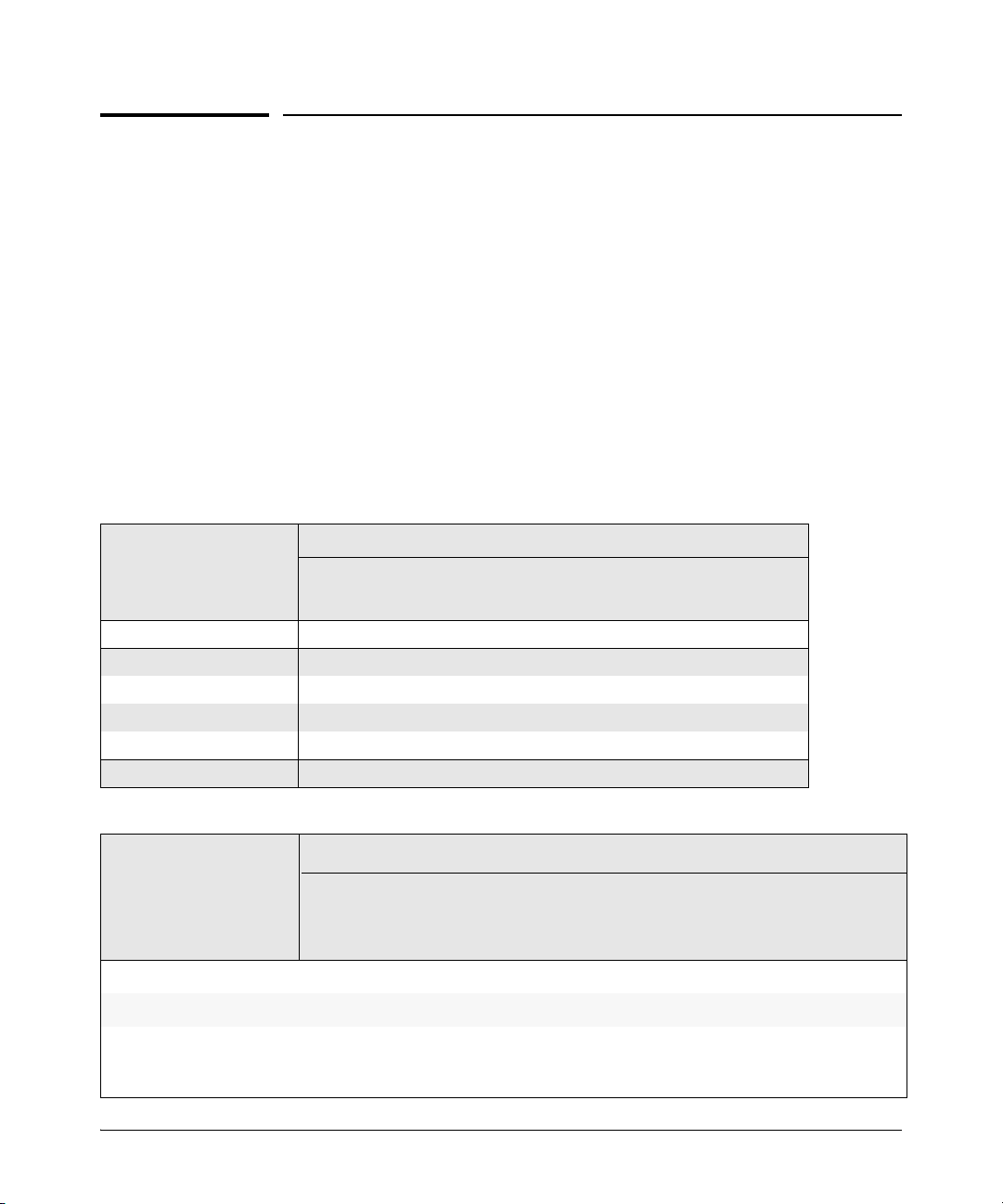
VLAN Features
Feature Default Menu CLI WebAgent
view existing VLANs n/a page 1-22
configuring static
VLANs
VLANs enable you to group users by logical function instead of physical
location. This helps to control bandwidth usage within your network by
allowing you to group high-bandwidth users on low-traffic segments and to
organize users from different LAN segments according to their need for
common resources and/or their use of individual protocols. You can also
improve traffic control at the edge of your network by separating traffic of
different protocol types. VLANs can also enhance your network security by
creating separate subnets to help control in-band access to specific network
resources.
default VLAN with
VID = 1
thru 1-27
page 1-22
thru 1-27
page 1-28 page 1-43
page 1-27 page 1-43
1-2
General VLAN Operation
A VLAN is comprised of multiple ports operating as members of the same
subnet (broadcast domain). Ports on multiple devices can belong to the same
VLAN, and traffic moving between ports in the same VLAN is bridged (or
“switched”). (Traffic moving between different VLANs must be routed.) A
static VLAN is an 802.1Q-compliant VLAN configured with one or more ports
that remain members regardless of traffic usage. (A dynamic VLAN is an
802.1Q-compliant VLAN membership that the switch temporarily creates on
a port to provide a link to another port in the same VLAN on another device.)
This chapter describes static VLANs configured for port-based or protocolbased operation. Static VLANs are configured with a name, VLAN ID number
(VID), and port members. (For dynamic VLANs, refer to chapter 2, “GVRP” .)
By default, the switches covered in this guide are 802.1Q VLAN-enabled and
allow up to 2048 static and dynamic VLANs. (The default static VLAN setting
is 256). 802.1Q compatibility enables you to assign each switch port to multiple
VLANs, if needed.
Page 25

Static Virtual LANs (VLANs)
Introduction
Types of Static VLANs Available in the Switch
Port-Based VLANs
This type of static VLAN creates a specific layer-2 broadcast domain comprised of member ports that bridge IPv4 traffic among themselves. Port-Based
VLAN traffic is routable on the switches covered in this guide.
Protocol-Based VLANs
This type of static VLAN creates a layer-3 broadcast domain for traffic of a
particular protocol, and is comprised of member ports that bridge traffic of
the specified protocol type among themselves. Some protocol types are
routable on the switches covered in this guide. Refer to table 1-1 on page 1-5.
Designated VLANs
The switch uses these static, port-based VLAN types to separate switch
management traffic from other network traffic. While these VLANs are not
limited to management traffic only, they can provide improved security and
availability for management traffic.
■ The Default VLAN: This port-based VLAN is always present in the switch
and, in the default configuration, includes all ports as members (page 1-
49).
■ The Primary VLAN: The switch uses this port-based VLAN to run certain
features and management functions, including DHCP/Bootp responses
for switch management. In the default configuration, the Default VLAN is
also the Primary VLAN. However, you can designate another, port-based,
non-default VLAN, as the Primary VLAN (page 1-49).
■ The Secure Management VLAN: This optional, port-based VLAN estab-
lishes an isolated network for managing the HP switches that support this
feature. Access to this VLAN and to the switch’s management functions
are available only through ports configured as members (page 1-50).
■ Voice VLANs: This optional, port-based VLAN type enables you to sepa-
rate, prioritize, and authenticate voice traffic moving through your network, and to avoid the possibility of broadcast storms affecting VoIP
(Voice-over-IP) operation (page 1-58).
1-3
Page 26

Static Virtual LANs (VLANs)
Terminology
Note In a multiple-VLAN environment that includes some older switch models there
may be problems related to the same MAC address appearing on different
ports and VLANs on the same switch. In such cases the solution is to impose
some cabling and VLAN restrictions. For more on this topic, refer to “Multiple
VLAN Considerations” on page 1-17.
Terminology
Dynamic VLAN: An 802.1Q VLAN membership temporarily created on a port
linked to another device, where both devices are running GVRP. (See also
Static VLAN.) For more information, refer to chapter 2, “GVRP” .
Static VLAN: A port-based or protocol-based VLAN configured in switch
memory. (See also Dynamic VLAN.)
Tagged Packet: A packet that carries an IEEE 802.1Q VLAN ID (VID), which
is a two-byte extension that precedes the source MAC address field of an
ethernet frame. A VLAN tag is layer 2 data and is transparent to higher
layers.
1-4
Tagged VLAN: A VLAN that complies with the 802.1Q standard, including
priority settings, and allows a port to join multiple VLANs. (See also
Untagged VLAN.)
Untagged Packet: A packet that does not carry an IEEE 802.1Q VLAN ID
(VID).
Untagged VLAN: A VLAN that does not use or forward 802.1Q VLAN tagging,
including priority settings. A port can be a member of only one untagged
VLAN of a given type (port-based and the various protocol-based types).
(See also Tagged VLAN.)
VID: The acronym for a VLAN Identification Number. Each 802.1Q-compliant
VLAN must have its own unique VID number, and that VLAN must be given
the same VID in every device in which it is configured.
Page 27

Static VLAN Operation
A group of networked ports assigned to a VLAN form a broadcast domain that
is separate from other VLANs that may be configured on the switch. On a given
switch, packets are bridged between source and destination ports that belong
to the same VLAN. Thus, all ports passing traffic for a particular subnet
address should be configured to the same VLAN. Cross-domain broadcast
traffic in the switch is eliminated and bandwidth is saved by not allowing
packets to flood out all ports.
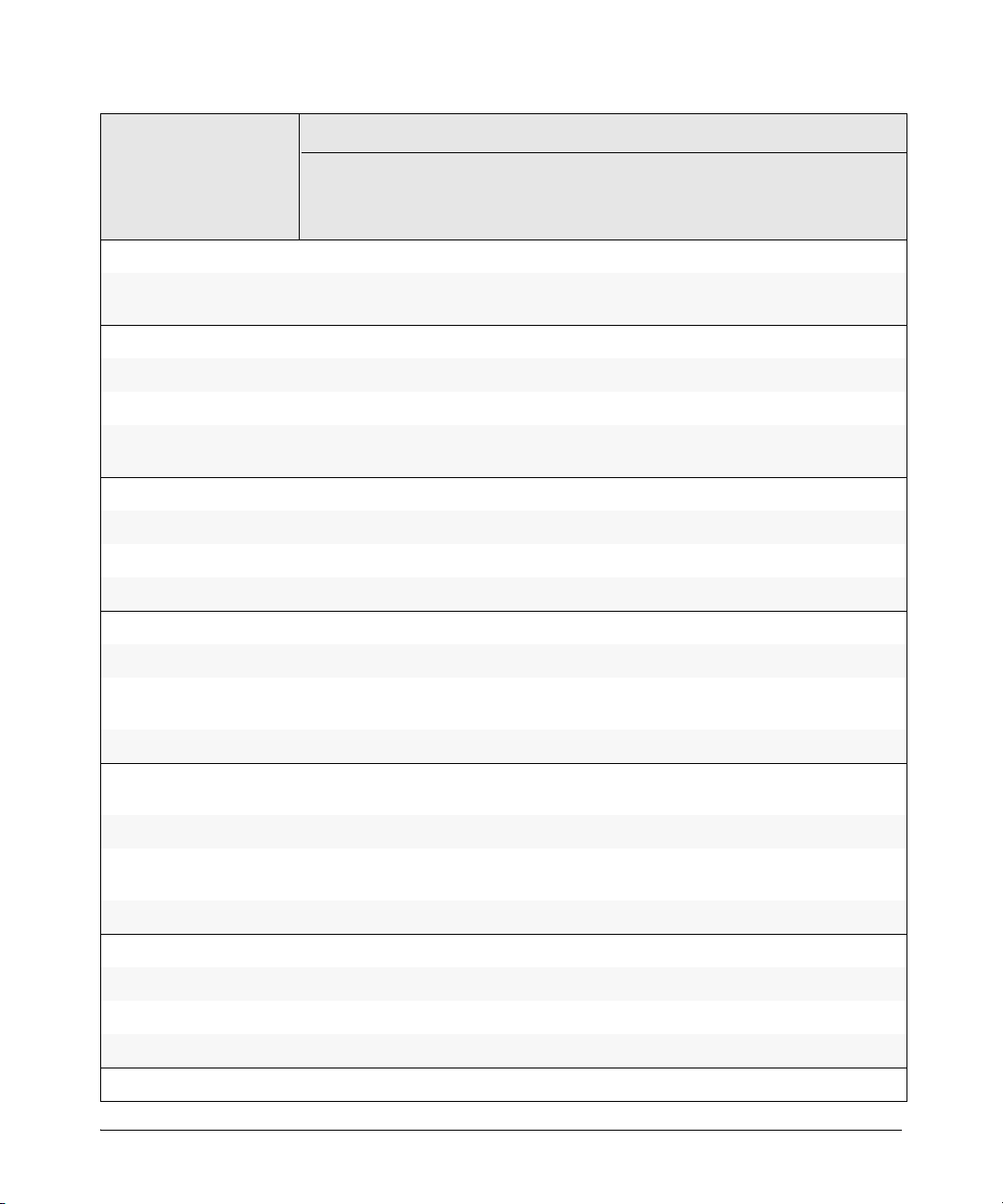
Table 1-1. Comparative Operation of Port-Based and Protocol-Based VLANs
Port-Based VLANs Protocol-Based VLANs
IP
Addressing
Usually configured with at least one unique IP
address. You can create a port-based VLAN without an IP address. However, this limits the switch
features available to ports on that VLAN. (Refer to
“How IP Addressing Affects Switch Operation” in
the chapter “Configuring IP Addressing” in the
Basic Operation Guide.)
You can also use multiple IP addresses to create
multiple subnets within the same VLAN. (For more
on this topic, refer to the chapter on “Configuring
IP Addressing” in the Baic Operation Guide.)
You can configure IP addresses on all protocol
VLANs. However, IP addressing is used only on IPv4
and IPv6 protocol VLANs.
Restrictions: When you configure an IP address on
a VLAN interface, the following restrictions apply:
Loopback interfaces share the same IP address
space with VLAN configurations. The maximum
number of IP addresses supported on a switch is
2048, which includes all IP addresses configured
for both VLANs and loopback interfaces (except
for the default loopback IP address 127.0.0.1).
Each IP address that you configure on a VLAN
interface must be unique in the switch. This
means that the address cannot be used by a VLAN
interface or another loopback interface.
For more information, refer to the chapter on
“Configuring IP Addressing” in the Basic Operation
Guide.
Static Virtual LANs (VLANs)
Static VLAN Operation
1-5
Page 28

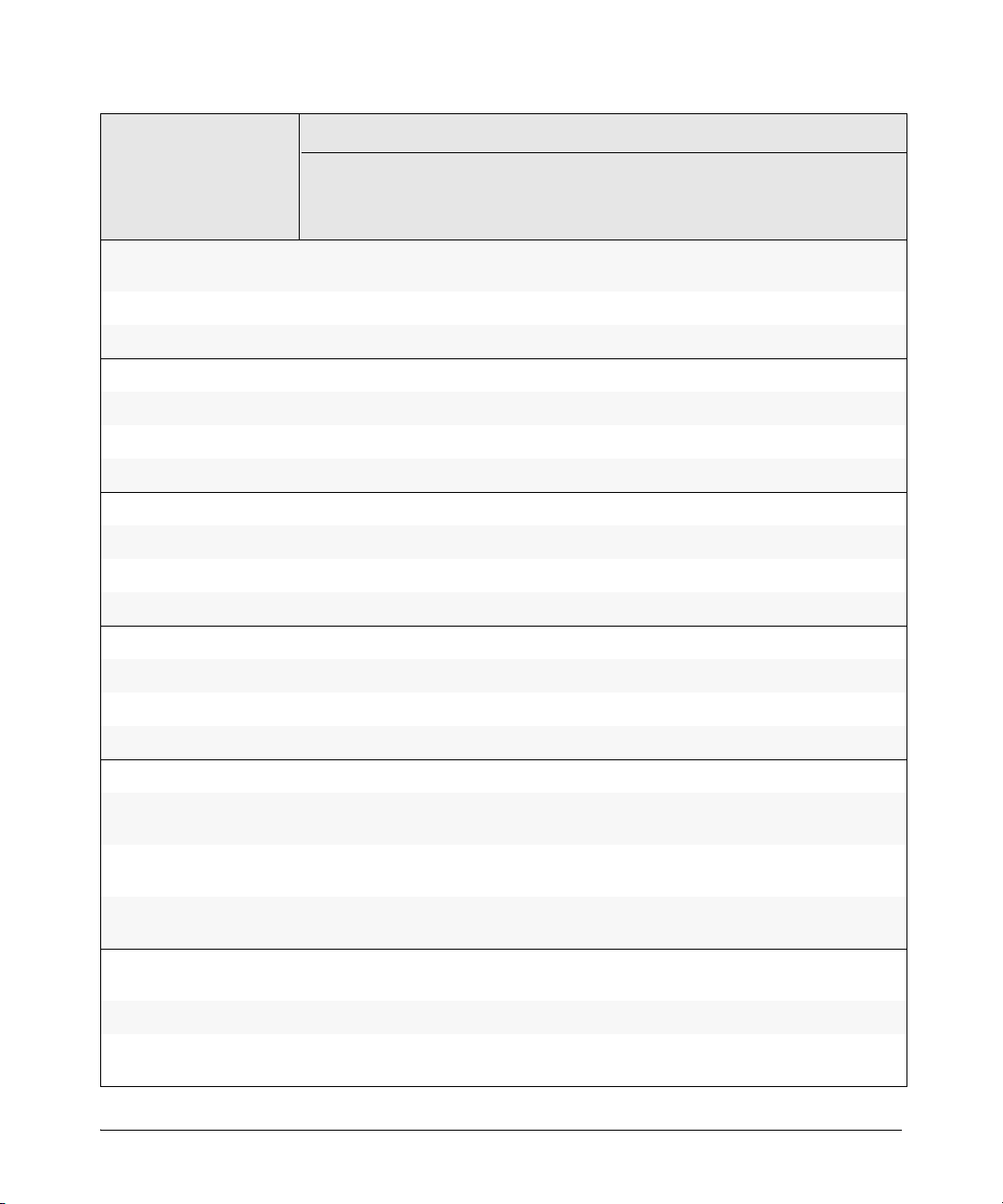
Static Virtual LANs (VLANs)
Static VLAN Operation
Port-Based VLANs Protocol-Based VLANs
Untagged
VLAN
Membership
Tagged VLAN
Membership
Routing The switch can internally route IP (IPv4) traffic
Commands
for
Configuring
Static VLANs
A port can be a member of one untagged, portbased VLAN. All other port-based VLAN
assignments for that port must be tagged.
A port can be a tagged member of any port-based
VLAN. See above.
between port-based VLANs and between portbased and IPv4 protocol-based VLANs if the switch
configuration enables IP routing.
If the switch is not configured to route traffic
internally between port-based VLANs, then an
external router must be used to move traffic
between VLANs.
vlan < VID > [ tagged | untagged < [e] port-list >] vlan <
A port can be an untagged member of one protocol
VLAN of a specific protocol type (such as IPX or IPv6).
If the same protocol type is configured in multiple
protocol VLANs, then a port can be an untagged
member of only one of those protocol VLANs. For
example, if you have two protocol VLANs, 100 and
200, and both include IPX, then a port can be an
untagged member of either VLAN 100 or VLAN 200,
but not both VLANs.
A port’s untagged VLAN memberships can include up
to four different protocol types. This means that a port
can be an untagged member of one of the following:
• Four single-protocol VLANs
• Two protocol VLANs where one VLAN includes a
single protocol and the other includes up to three
protocols
• One protocol VLAN where the VLAN includes four
protocols
A port can be a tagged member of any protocolbased VLAN. See above.
If the switch configuration enables IP routing, the
switch can internally route IPv4 traffic as follows:
• Between multiple IPv4 protocol-based VLANs
• Between IPv4 protocol-based VLANs and portbased VLANs.
Other protocol-based VLANs require an external
router for moving traffic between VLANs.
Note: NETbeui and SNA are non-routable protocols.
End stations intended to receive traffic in these
protocols must be attached to the same physical
network.
VID > protocol < ipx | ipv4 | ipv6 | arp |
appletalk | sna | netbeui >
vlan <
VID > [ tagged | untagged < [e] port-list >]
1-6
VLAN Environments
You can configure different VLAN types in any combination. Note that the
default VLAN will always be present. (For more on the default VLAN, refer to
“VLAN Support and the Default VLAN” on page 1-49.)
Page 29
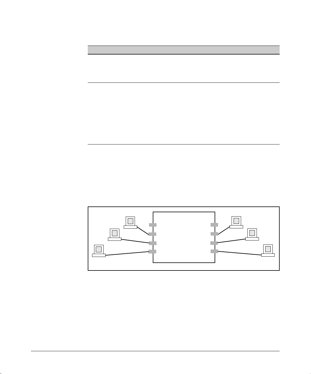
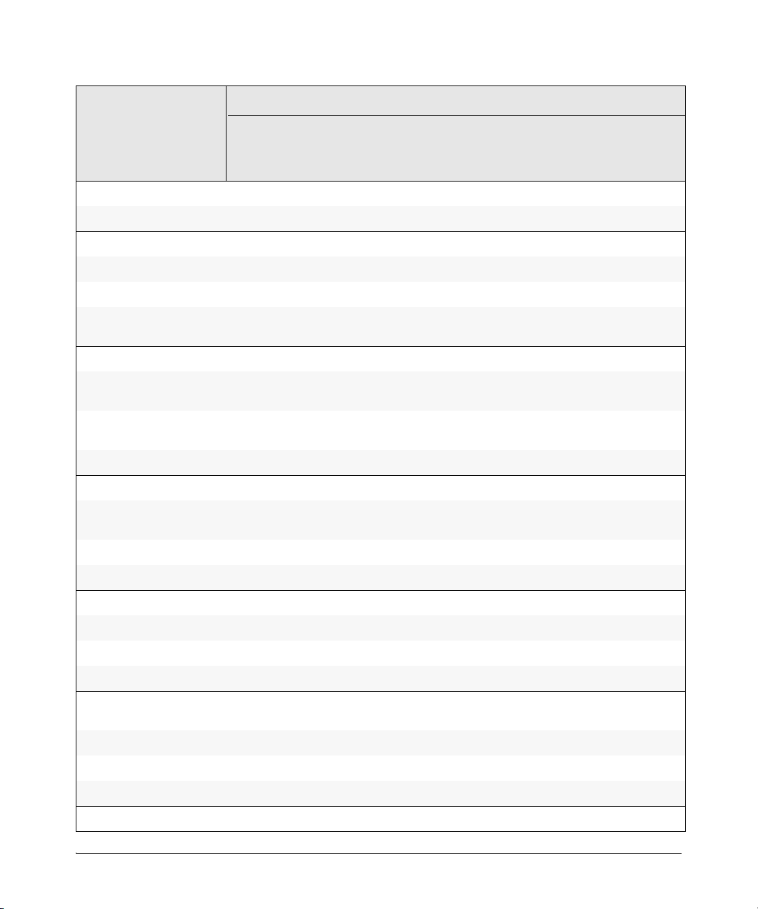
Table 1-2. VLAN Environments
VLAN 1
A2
A3
A4
A7
A6
A5
A1
A8
VLAN Environment Elements
The default VLAN (port-based;
VID of “1”) Only
In the default VLAN configuration, all ports belong to VLAN
1 as untagged members.
VLAN 1 is a port-based VLAN, for IPv4 traffic.
Static Virtual LANs (VLANs)
Static VLAN Operation
Multiple VLAN Environment In addition to the default VLAN, the configuration can include
one or more other port-based VLANs and one or more
protocol VLANs. (The switches covered in this guide allow
up to 2048 (vids up to 4094) VLANs of all types.) Using VLAN
tagging, ports can belong to multiple VLANs of all types.
Enabling routing on the switch enables the switch to route
IPv4 traffic between port-based VLANs and between portbased VLANs and IPv4 protocol VLANs. Routing other types
of traffic between VLANs requires an external router
capable of processing the appropriate protocol(s).
VLAN Operation
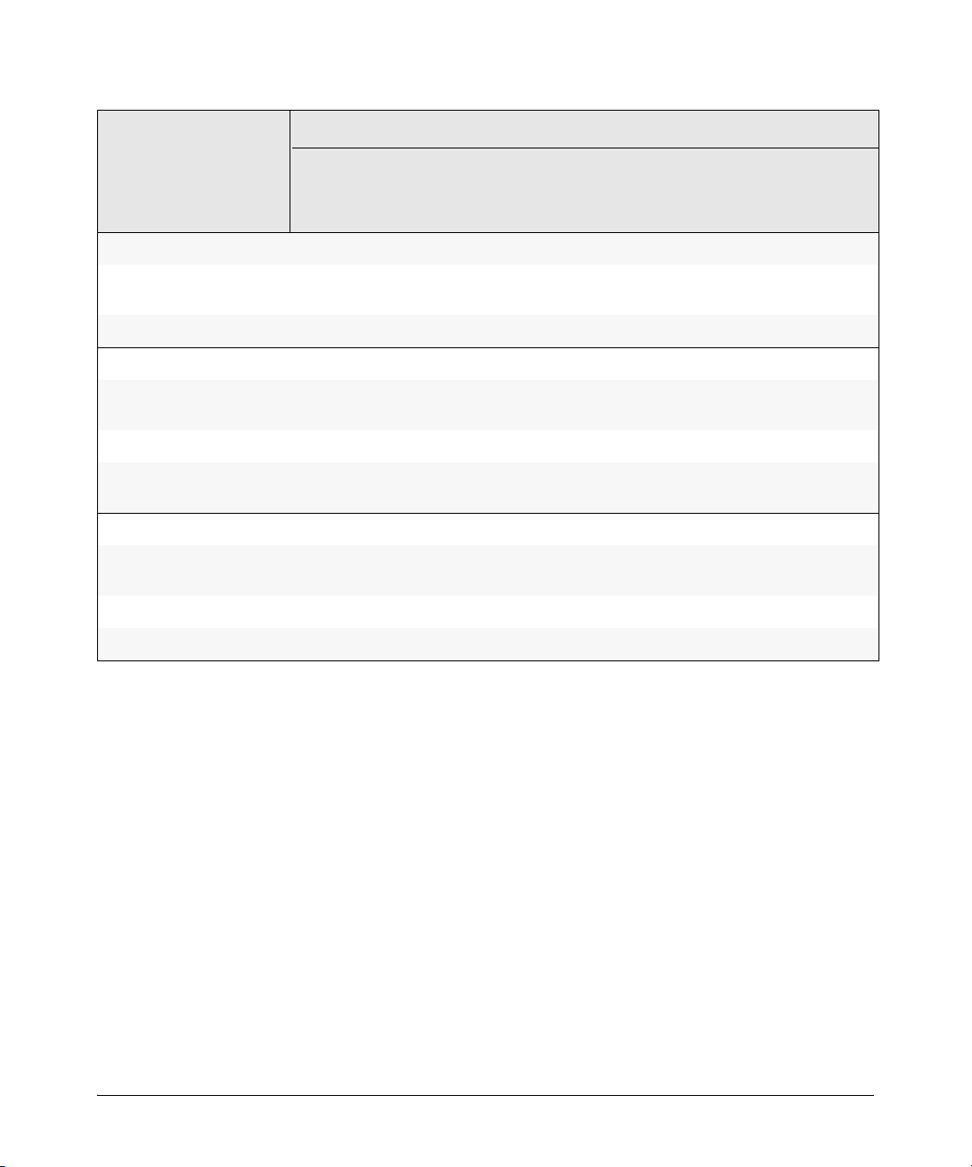
The Default VLAN. In figure 1-1, all ports belong to the default VLAN, and
devices connected to these ports are in the same broadcast domain. Except
for an IP address and subnet, no configuration steps are needed.
Figure 1-1. Example of a Switch in the Default VLAN Configuration
Multiple Port-Based VLANs. In figure 1-2, routing within the switch is
disabled (the default). This means that communication between any routable
VLANs on the switch must go through the external router. In this case, VLANs
“W” and “X” can exchange traffic through the external router, but traffic in
VLANs “Y” and “Z” is restricted to the respective VLANs. Note that VLAN 1,
the default VLAN, is also present, but not shown. (The default VLAN cannot
be deleted from the switch. However, ports assigned to other VLANs can be
removed from the default VLAN, if desired.) If internal (IP) routing is enabled
1-7
Page 30
Static Virtual LANs (VLANs)
External
Router
Switch with Multiple
VLANs Configured
and Internal Routing
Disabled
A2
A3
A4
A7
A6
A5
A1
A8
VLAN Z
VLAN Y
VLAN X
VLAN W
Static VLAN Operation
on the switch, then the external router is not needed for traffic to move
between port-based VLANs.
Figure 1-2. Example of Multiple VLANs on the Switch
Protocol VLAN Environment. Figure 1-2 can also be applied to a protocol
VLAN environment. In this case, VLANs “W” and “X” represent routable
protocol VLANs. VLANs “Y” and “Z” can be any protocol VLAN. As noted for
the discussion of multiple port-based VLANs, VLAN 1 is not shown. Enabling
internal (IP) routing on the switch allows IP traffic to move between VLANs
on the switch. However, routable, non-IP traffic always requires an external
router.
1-8
Routing Options for VLANs
Table 1-3. Options for Routing Between VLAN Types in the Switch
PortBased
Port-Based Yes — Yes — — — — —
Protocol
IPX — Yes
IPX IPv4 IPv6 ARP Apple
-Talk
1
———— — —
IP v4 Yes — Yes — — — — —
1
IPv6 — — — Yes
ARP — — — — Yes
AppleTalk — — — — — Yes
—— — —
1
—— —
1
2
SNA
Netbeui
——
2
Page 31

Static Virtual LANs (VLANs)
HP
Switch
802.1Q-Compliant
Server
Static VLAN Operation
PortBased
2
SNA
NETbeui
1
Requires an external router to route between VLANs.
2
Not a routable protocol type. End stations intended to receive traffic in these
protocols must be attached to the same physical network.
— ————— — —
2
— ————— — —
IPX IPv4 IPv6 ARP Apple
-Talk
SNA2Netbeui
2
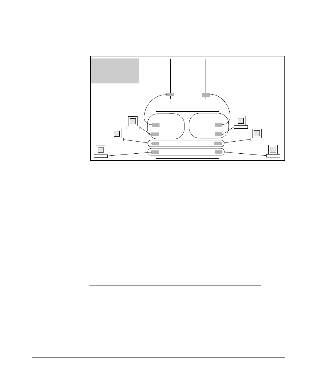
Overlapping (Tagged) VLANs
A port can be a member of more than one VLAN of the same type if the device
to which the port connects complies with the 802.1Q VLAN standard. For
example, a port connected to a central server using a network interface card
(NIC) that complies with the 802.1Q standard can be a member of multiple
VLANs, allowing members of multiple VLANs to use the server. Although these
VLANs cannot communicate with each other through the server, they can all
access the server over the same connection from the switch. Where VLANs
overlap in this way, VLAN “tags” are used in the individual packets to distinguish between traffic from different VLANs. A VLAN tag includes the particular VLAN I.D. (VID) of the VLAN on which the packet was generated.
Figure 1-3. Example of Overlapping VLANs Using the Same Server
Similarly, using 802.1Q-compliant switches, you can connect multiple VLANs
through a single switch-to-switch link.
1-9
Page 32

Static Virtual LANs (VLANs)
Red Server
HP Switch
Blue Server
HP
Switch
Red
VLAN
Red
VLAN
Blue
VLAN
Blue
VLAN
Red
VLAN
The same link carries Red
VLAN and Blue VLAN traffic.
Red VLAN
Blue VLAN
Red Server
HP Switch
Blue Server
HP
Switch
Red
VLAN
Red
VLAN
Blue
VLAN
Blue
VLAN
Red
VLAN
VLAN tagging
enables the Link to
carry Red VLAN and
Blue VLAN Traffic
Blue
VLAN
Non-802.1Q
Switch
The legacy (non-802.1Q
compliant) switch requires a
separate link for each VLAN.
Static VLAN Operation
Figure 1-4. Example of Connecting Multiple VLANs Through the Same Link
Introducing Tagged VLAN Technology into Networks Running Legacy
(Untagged) VLANs. You can introduce 802.1Q-compliant devices into net-
works that have built untagged VLANs based on earlier VLAN technology. The
fundamental rule is that legacy/untagged VLANs require a separate link for
each VLAN, while 802.1Q, or tagged VLANs can combine several VLANs in one
link. This means that on the 802.1Q-compliant device, separate ports (configured as untagged) must be used to connect separate VLANs to non-802.1Q
devices.
1-10
Figure 1-5. Example of Tagged and Untagged VLAN Technology in the Same
Network
For more information on VLANs, refer to:
■ “Overview of Using VLANs” (page 1-49)
■ “Menu: Configuring VLAN Parameters (page 1-21)
Page 33

Static Virtual LANs (VLANs)
Example of Per-Port
VLAN Configuration
with GVRP Disabled
(the default)
Example of Per-Port
VLAN Configuration
with GVRP Enabled
Enabling GVRP causes “No” to display as “Auto”.
Static VLAN Operation
■ “CLI: Configuring VLAN Parameters” (page 1-21)
■ “WebAgent: Viewing and Configuring VLAN Parameters” (page 1-43)
■ “VLAN Tagging Information” (page 1-44)
■ “Effect of VLANs on Other Switch Features” (page 1-60)
■ “VLAN Restrictions” (page 1-62)
Per-Port Static VLAN Configuration Options
The following figure and table show the options you can use to assign
individual ports to a static VLAN. Note that GVRP, if configured, affects these
options and VLAN behavior on the switch. The display below shows the perport VLAN configuration options. Table 1-4 briefly describes these options.
Figure 1-6. Comparing Per-Port VLAN Options With and Without GVRP
Table 1-4. Per-Port VLAN Configuration Options
Parameter Effect on Port Participation in Designated VLAN
Tagged
Untagged
Allows the port to join multiple VLANs.
Allows VLAN connection to a device that is configured for an untagged
VLAN instead of a tagged VLAN. A port can be an untagged member of
only one port-based VLAN. A port can also be an untagged member of only
one protocol-based VLAN for any given protocol type. For example, if the
switch is configured with the default VLAN plus three protocol-based
VLANs that include IPX, then port 1 can be an untagged member of the
default VLAN and one of the protocol-based VLANS.
1-11
Page 34

Static Virtual LANs (VLANs)
VLAN Operating Rules
Parameter Effect on Port Participation in Designated VLAN
No
- or Auto
Forbid
VLAN Operating Rules
■ DHCP/Bootp: If you are using DHCP/Bootp to acquire the switch’s
■ Per-VLAN Features: IGMP and some other features operate on a “per
■ Default VLAN: You can rename the default VLAN, but you cannot change
■ VLAN Port Assignments: Any ports not specifically removed from the
■ Voice-Over-IP (VoIP): VoIP operates only over static, port-based VLANs.
■ Multiple VLAN Types Configured on the Same Port: A port can
■ Protocol Capacity: A protocol-based VLAN can include up to four
No
: Appears when the switch is not GVRP-enabled; prevents the port from
joining that VLAN.
Auto: Appears when GVRP is enabled on the switch; allows the port to
dynamically join any advertised VLAN that has the same VID
Prevents the port from joining the VLAN, even if GVRP is enabled on the
switch.
configuration, packet time-to-live, and TimeP information, you must designate the VLAN on which DHCP is configured for this purpose as the
Primary VLAN. (In the factory-default configuration, the DEFAULT_VLAN
is the Primary VLAN.)
VLAN” basis. This means you must configure such features separately for
each VLAN in which you want them to operate.
its VID (1) or delete it from the switch.
default VLAN remain in the DEFAULT_VLAN, regardless of other port
assignments. Also, a port must always be a tagged or untagged member
of at least one port-based VLAN.
simultaneously belong to both port-based and protocol-based VLANs.
protocol types. In protocol VLANs using the IPv4 protocol, ARP must be
one of these protocol types (to support normal IP network operation).
Otherwise, IP traffic on the VLAN is disabled. If you configure an IPv4
protocol VLAN that does not already include the ARP VLAN protocol, the
switch displays this message:
1-12
Page 35

Static Virtual LANs (VLANs)
HP Switch(config)# vlan 97 protocol ipv4
IPv4 assigned without ARP, this may result in
undeliverable IP packets.
Indicates a protocol VLAN configured
with IPv4, but not ARP.
VLAN Operating Rules
■ Deleting Static VLANs: On the switches covered in this guide you can
delete a VLAN regardless of whether there are currently any ports belonging to that VLAN. (The ports are moved to the default VLAN.)
■ Adding or Deleting VLANs: Changing the number of VLANs supported
on the switch requires a reboot. (From the CLI, you must perform a write
memory command before rebooting.) Other VLAN configuration changes
are dynamic.
■ Inbound Tagged Packets: If a tagged packet arrives on a port that is not
a tagged member of the VLAN indicated by the packet’s VID, the switch
drops the packet. Similarly, the switch will drop an inbound, tagged packet
if the receiving port is an untagged member of the VLAN indicated by the
packet’s VID.
■ Untagged Packet Forwarding: To enable an inbound port to forward
an untagged packet, the port must be an untagged member of either a
protocol VLAN matching the packet’s protocol or an untagged member of
a port-based VLAN. That is, when a port receives an incoming, untagged
packet, it processes the packet according to the following ordered criteria:
a. If the port has no untagged VLAN memberships, the switch drops the
packet.
b. If the port has an untagged VLAN membership in a protocol VLAN
that matches the protocol type of the incoming packet, then the
switch forwards the packet on that VLAN.
c. If the port is a member of an untagged, port-based VLAN, the switch
forwards the packet to that VLAN. Otherwise, the switch drops the
packet.
1-13
Page 36

Static Virtual LANs (VLANs)
Yes
Port “X” receives
an inbound,
untagged Packet.
Is the
port an untagged
member of any
VLANs?
No
Does the
packet’s protocol
match the protocol of
an untagged VLAN
membership on
the port?
Drop the
packet.
No
Yes
Forward the
packet on that
protocol VLAN.
Is the
port a member
of an untagged,
port-based
VLAN?
No
Drop the
packet.
Yes
Forward the
packet on the
port-based VLAN.
VLAN Operating Rules
1-14
Figure 1-7. Untagged VLAN Operation
■ Tagged Packet Forwarding: If a port is a tagged member of the same
VLAN as an inbound, tagged packet received on that port, then the switch
forwards the packet to an outbound port on that VLAN. (To enable the
forwarding of tagged packets, any VLAN to which the port belongs as a
Page 37

Static Virtual LANs (VLANs)
Yes
Port “X” receives
an inbound,
tagged Packet
From VLAN “A”.
Is port
“X” a tagged
member of
VLAN “A”?
No
Forward the
packet to any port
“Y” on VLAN “A”
for outbound
transmission.
Drop the
packet.
Note that the outbound
port can be either a
tagged or untagged
member of the VLAN.
VLAN Operating Rules
tagged member must have the same VID as that carried by the inbound,
tagged packets generated on that VLAN.)
Figure 1-8. Tagged VLAN Operation
See also “Multiple VLAN Considerations” on page 1-17.
Caution Rate-limiting may behave unpredictably on a VLAN if the VLAN spans
multiple modules or port-banks. This also applies if a port on a different
module or port-bank is added to an existing VLAN. HP does not recommend
configuring rate-limiting on VLANs that include ports spanning modules or
port-banks.
In figure 1-9 ports 2, 3, and 24 form one VLAN. The ports are in the same portbank, which includes ports 1 through 24. Ports 28, 29, and 32 form a second
VLAN. These ports are also in the same port-bank, which includes ports 25
through 48. Rate-limiting will operate as expected for these VLANs.
1-15
Page 38

Static Virtual LANs (VLANs)
Port-bank 1-24 Port-bank 25-48
VLAN A
VLAN B
General Steps for Using VLANs
Figure 1-9. Example of VLANs Using Ports from the Same Port-Bank for Each VLAN
1-16
General Steps for Using VLANs
1. Plan your VLAN strategy and create a map of the logical topology that will
result from configuring VLANs. Include consideration for the interaction
between VLANs and other features such as Spanning Tree Protocol, port
trunking, and IGMP. (Refer to “Effect of VLANs on Other Switch Features”
on page 1-60.) If you plan on using dynamic VLANs, include the port
configuration planning necessary to support this feature. (Refer to chapter 2, “GVRP” .)
By default, VLAN support is enabled for up to 256 VLANs.
2. Configure at least one VLAN in addition to the default VLAN.
3. Assign the desired switch ports to the new VLAN(s).
4. If you are managing VLANs with SNMP in an IP network, the VLAN
through which you are managing the switch must have an IP address. For
information on the procedure and restrictions when you configure an IP
address on a VLAN interface, refer to Table 1-1 on page 1-5.
Page 39

Static Virtual LANs (VLANs)
Multiple VLAN Considerations
Multiple VLAN Considerations
Switches use a forwarding database to maintain awareness of which external
devices are located on which VLANs. Some switches, such as the switches
covered in this guide, have a multiple forwarding database, which means the
switch allows multiple database entries of the same MAC address, with each
entry showing the (different) source VLAN and source port. Other switch
models have a single forwarding database, which means they allow only one
database entry of a unique MAC address, along with the source VLAN and
source port on which it is found. All VLANs on a switch use the same MAC
address. Thus, connecting a multiple forwarding database switch to a single
forwarding database switch where multiple VLANs exist imposes some
cabling and port VLAN assignment restrictions. Table 1-5 illustrates the functional difference between the two database types.
Table 1-5. Example of Forwarding Database Content
Multiple Forwarding Database Single Forwarding Database
MAC Address Destination
VLAN ID
0004ea-84d9f4 1 A5 0004ea-84d9f4 100 A9
0004ea-84d9f4 22 A12 0060b0-880af9 105 A10
0004ea-84d9f4 44 A20 0060b0-880a81 107 A17
0060b0-880a81 33 A20
This database allows multiple destinations
for the same MAC address. If the switch
detects a new destination for an existing
MAC entry, it just adds a new instance of that
MAC to the table.
Destination
Port
MAC Address Destination
VLAN ID
This database allows only one destination
for a MAC address. If the switch detects a
new destination for an existing MAC entry,
it replaces the existing MAC instance with
a new instance showing the new
destination.
Destination
Port
Table 1-6 lists the database structure of current HP switch models.
1-17
Page 40

Static Virtual LANs (VLANs)
Multiple VLAN Considerations
Table 1-6. Forwarding Database Structure for Managed HP Switches
Multiple Forwarding Databases* Single Forwarding Database*
Series E8200zl switches Switch E1600M/E2400M/
Switch E6600 Switch E4000M/E8000M
Series E6400cl switches Series E2500 switches
Switch E6200yl Switch E2000
Switch E6108 Switch E800T
Series E5400zl switches
Series E5300xl switches
Series E4200vl switches
Series E4100gl switches
Series E3500 switches
Series E3500yl switches
Series E3400cl switches
Switch E2810
Series E2800 switches
Series E2600/2600-PWR switches
Series E2510 switches
*To determine whether other vendors’ devices use singleforwarding or multiple-forwarding database architectures, refer to
the documentation provided for those devices.
E2424M
1-18
Single Forwarding Database Operation
When a packet arrives with a destination MAC address that matches a MAC
address in the switch’s forwarding table, the switch tries to send the packet
to the port listed for that MAC address. But, if the destination port is in a
different VLAN than the VLAN on which the packet was received, the switch
drops the packet. This is not a problem for a switch with a multiple forwarding
database (refer to table 1-6, above) because the switch allows multiple
instances of a given MAC address; one for each valid destination. However, a
switch with a single forwarding database allows only one instance of a given
MAC address. If (1) you connect the two types of switches through multiple
ports or trunks belonging to different VLANs, and (2) enable routing on the
switch having the multiple forwarding database; then, on the switch having
the single forwarding database, the port and VLAN record it maintains for the
Page 41

Static Virtual LANs (VLANs)
Switch 8000M
VLAN 1
VLAN 2
E8212zl Switch
Routing Enabled
(Same MAC address for all
VLANs.)
VLAN 1
VLAN 2
This switch has multiple
forwarding databases.
This switch has a single
forwarding database.
PC “A”
PC “B”
A1
B1
C1
D1
Multiple VLAN Considerations
connected multiple-forwarding-database switch can frequently change. This
causes poor performance and the appearance of an intermittent or broken
connection.
Example of an Unsupported Configuration and How To Correct It
The Problem. In figure 1-10, the MAC address table for Switch 8000M will
sometimes record the switch as accessed on port A1 (VLAN 1), and other times
as accessed on port B1 (VLAN 2):
Figure 1-10. Example of Invalid Configuration for Single-Forwarding to MultipleForwarding Database Devices in a Multiple VLAN Environment
In figure 1-10, PC “A” sends an IP packet to PC “B”.
1. The packet enters VLAN 1 in the Switch 8000 with the 8212zl switch’s MAC
2. PC “A” now sends a second packet to PC “B”. The packet again enters
address in the destination field. Because the 8000M has not yet learned
this MAC address, it does not find the address in its address table, and
floods the packet out all ports, including the VLAN 1 link (port “A1”) to
the 8212zl switch. The 8212zl switch then routes the packet through the
VLAN 2 link to the 8000M, which forwards the packet on to PC “B”.
Because the 8000M received the packet from the 8212zl switch on VLAN
2 (port “B1”), the 8000M’s single forwarding database records the 8212zl
switch as being on port “B1” (VLAN 2).
VLAN 1 in the Switch 8000 with the 8212zl switch’s MAC address in the
destination field. However, this time the Switch 8000M’s single forwarding
database indicates that the 8212zl is on port B1 (VLAN 2), and the 8000M
drops the packet instead of forwarding it.
1-19
Page 42

Static Virtual LANs (VLANs)
Switch 8000M
VLAN 1
VLAN 2
E8212zl Switch
(Routing Enabled)
VLAN 1
VLAN 2
This switch has multiple
forwarding databases.
This switch has a single
forwarding database.
PC “A”
PC “B”
VLAN
1 & 2
VLAN
1 & 2
A1
C1
Multiple VLAN Considerations
3. Later, the 8212zl switch transmits a packet to the 8000M through the VLAN
The Solution. To avoid the preceding problem, use only one cable or port
trunk between the single-forwarding and multiple-forwarding database
devices, and configure the link with multiple, tagged VLANs.
1 link, and the 8000M updates its address table to indicate that the 8212zl
switch is on port A1 (VLAN 1) instead of port B1 (VLAN 2). Thus, the
8000M’s information on the location of the 8212zl switch changes over
time. For this reason, the 8000M discards some packets directed through
it for the 8212zl switch, resulting in poor performance and the appearance
of an intermittent or broken link.
1-20
Figure 1-11. Example of a Solution for Single-Forwarding to Multiple-Forwarding
Database Devices in a Multiple VLAN Environment
Now, the 8000M forwarding database always lists the 8212zl MAC address on
port A1, and the 8000M will send traffic to either VLAN on the 8212zl.
To increase the network bandwidth of the connection between the devices,
you can use a trunk of multiple physical links rather than a single physical link.
Multiple Forwarding Database Operation
If you want to connect one of the switches covered by this guide to another
switch that has a multiple forwarding database, you can use either or both of
the following connection options:
■ A separate port or port trunk interface for each VLAN. This results in a
forwarding database having multiple instances of the same MAC address
with different VLAN IDs and port numbers. (See table 1-5.) The fact that
the switches covered by this guide use the same MAC address on all VLAN
interfaces causes no problems.
Page 43

Static Virtual LANs (VLANs)
4108gl Switch
VLAN 1
VLAN 2
E8212zl Switch
VLAN 1
VLAN 2
Both switches have
multiple forwarding
databases.
■ The same port or port trunk interface for multiple (tagged) VLANs. This
Configuring VLANs
results in a forwarding database having multiple instances of the same
MAC address with different VLAN IDs, but the same port number.
Allowing multiple entries of the same MAC address on different VLANs
enables topologies such as the following:
Figure 1-12. Example of a Valid Topology for Devices Having Multiple Forwarding
Databases in a Multiple VLAN Environment
Configuring VLANs
Menu: Configuring Port-Based VLAN Parameters
The Menu interface enables you to configure and view port-based VLANs.
Note The Menu interface configures and displays only port-based VLANs. The CLI
configures and displays port-based and protocol-based VLANs (page 1-27).
In the factory default state, support is enabled for up to 256 VLANs. (You can
reconfigure the switch to support up to 2048 (vids up to 4094) VLANs.) Also,
in the default configuration, all ports on the switch belong to the default VLAN
and are in the same broadcast/multicast domain. (The default VLAN is also
the default Primary VLAN—refer to “The Primary VLAN” on page 1-49.) In
addition to the default VLAN, you can configure additional static VLANs by
adding new VLAN names and VIDs, and then assigning one or more ports to
each VLAN. (The maximum of 2048 VLANs includes the default VLAN, all
additional static VLANs you configure, and any dynamic VLANs the switch
1-21
Page 44

Static Virtual LANs (VLANs)
Configuring VLANs
creates if you enable GVRP—page 2-1.) Note that each port can be assigned
to multiple VLANs by using VLAN tagging. (See “802.1Q VLAN Tagging” on
page 1-44.)
To Change VLAN Support Settings
This section describes:
■ Changing the maximum number of VLANs to support
■ Changing the Primary VLAN selection (See “Changing the Primary VLAN”
■ Enabling or disabling dynamic VLANs (Refer to chapter 2, “GVRP” .)
1. From the Main Menu select:
on page 1-37.)
2. Switch Configuration
8. VLAN Menu …
1. VLAN Support
You will then see the following screen:
1-22
Figure 1-13. The Default VLAN Support Screen
2. Press [E] (for E
dit), then do one or more of the following:
• To change the maximum number of VLANs, type the new number
(1 - 2048 allowed; default 256).
• To designate a different VLAN as the Primary VLAN, select the Primary
VLAN field and use the space bar to select from the existing options.
(Note that the Primary VLAN must be a static, port-based VLAN.)
• To enable or disable dynamic VLANs, select the GVRP Enabled field
and use the Space bar to toggle between options. (For GVRP information, refer to chapter 2, “GVRP” .)
Page 45

Static Virtual LANs (VLANs)
An asterisk indicates
you must reboot the
switch to implement
the new Maximum
VLANs setting.
Configuring VLANs
Note For optimal switch memory utilization, set the number of VLANs at the
number you will likely be using or a few more. If you need more VLANs later,
you can increase this number, but a switch reboot will be required at that time.
3. Press [Enter] and then [S] to save the VLAN support configuration and
return to the VLAN Menu screen.
If you changed the value for Maximum VLANs to support, you will see an
asterisk next to the VLAN Support option (see below).
Figure 1-14. VLAN Menu Screen Indicating the Need To Reboot the Switch
• If you changed the VLAN Support option, you must reboot the switch
before the Maximum VLANs change can take effect. You can go on to
configure other VLAN parameters first, but remember to reboot the
switch when you are finished.
• If you did not change the VLAN Support option, a reboot is not
necessary.
4. Press
[0] to return to the Main Menu.
Adding or Editing VLAN Names
Use this procedure to add a new VLAN or to edit the name of an existing VLAN.
1. From the Main Menu select:
2. Switch Configuration
8. VLAN Menu ….
2. VLAN Names
If multiple VLANs are not yet configured you will see a screen similar to
figure 1-15:
1-23
Page 46

Static Virtual LANs (VLANs)
Default VLAN
and VLAN ID
Configuring VLANs
Figure 1-15. The Default VLAN Names Screen
2. Press
[A] (for Add). You will then be prompted for a new VLAN name and
VLAN ID:
802.1Q VLAN ID : 1
Name : _
3. Type in a VID (VLAN ID number). This can be any number from 2 to 4094
that is not already being used by another VLAN. (The switch reserves “1”
for the default VLAN.)
Remember that a VLAN must have the same VID in every switch in which
you configure that same VLAN. (GVRP dynamically extends VLANs with
correct VID numbering to other switches. Refer to chapter 2, “GVRP” .)
4. Press [v] to move the cursor to the Name line and type the VLAN name (up
to 12 characters, with no spaces) of a new VLAN that you want to add,
then press
(Avoid these characters in VLAN names:
5. Press
[Enter].
@, #, $, ^, &, *, (, and ).)
[S] (for Save). You will then see the VLAN Names screen with the
new VLAN listed.
1-24
Page 47

Static Virtual LANs (VLANs)
Example of a New
VLAN and ID
Configuring VLANs
Figure 1-16. Example of VLAN Names Screen with a New VLAN Added
6. Repeat steps 2 through 5 to add more VLANs.
Remember that you can add VLANs until you reach the number specified
in the Maximum VLANs to support field on the VLAN Support screen (see
figure 1-13 on page 1-22). This includes any VLANs added dynamically due
to GVRP operation.
7. Return to the VLAN Menu to assign ports to the new VLAN(s) as described
in the next section, “Adding or Changing a VLAN Port Assignment”.
Adding or Changing a VLAN Port Assignment
Use this procedure to add ports to a VLAN or to change the VLAN assignment(s) for any port. (Ports not specifically assigned to a VLAN are automatically in the default VLAN.)
1. From the Main Menu select:
2. Switch Configuration
8. VLAN Menu …
3. VLAN Port Assignment
You will then see a VLAN Port Assignment screen similar to the following:
Note The “VLAN Port Assignment” screen displays up to 32 static, port-based
VLANs in ascending order, by VID. If the switch configuration includes more
than 32 such VLANs, use the CLI show vlans [ VID | ports < port-list >] command
to list data on VLANs having VIDs numbered sequentially higher than the first
32.
1-25
Page 48

Static Virtual LANs (VLANs)
Default: In this example,
the “VLAN-22” has been
defined, but no ports
have yet been assigned
to it. (“No” means the
port is not assigned to
that VLAN.)
Using GVRP? If you plan
on using GVRP, any
ports you don’t want to
join should be changed
to “Forbid”.
A port can be assigned
to several VLANs, but
only one of those
assignments can be
“Untagged”.
Configuring VLANs
Figure 1-17. Example of the Port-Based VLAN Port Assignment Screen in the Menu
Interface
2. To change a port’s VLAN assignment(s):
a. Press
[E] (for Edit).
b. Use the arrow keys to select a VLAN assignment you want to change.
c. Press the Space bar to make your assignment selection (No, Tagged,
Untagged, or Forbid).
Note For GVRP Operation: If you enable GVRP on the switch, “No”
1-26
converts to “Auto”, which allows the VLAN to dynamically join an
advertised VLAN that has the same VID. See “Per-Port Options for
Dynamic VLAN Advertising and Joining” on page 2-8.
Untagged VLANs: Only one untagged VLAN is allowed per port. Also,
there must be at least one VLAN assigned to each port. In the factory
default configuration, all ports are assigned to the default VLAN
(DEFAULT_VLAN).
For example, if you want ports A4 and A5 to belong to both
DEFAULT_VLAN and VLAN-22, and ports A6 and A7 to belong only to
VLAN-22, you would use the settings in figure page 1-27. (This example
assumes the default GVRP setting—disabled—and that you do not plan
to enable GVRP later.)
Page 49

Static Virtual LANs (VLANs)
Ports A4 and A5 are
assigned to both
VLANs.
Ports A6 and A7 are
assigned only to
VLAN-22.
All other ports are
assigned only to the
Default VLAN.
Configuring VLANs
Figure 1-18. Example of Port-Based VLAN Assignments for Specific Ports
For information on VLAN tags (“Untagged” and “Tagged”), refer to
“802.1Q VLAN Tagging” on page 1-44.
d. If you are finished assigning ports to VLANs, press [Enter] and then [S]
(for Save) to activate the changes you've made and to return to the
Configuration menu. (The console then returns to the VLAN menu.)
3. Return to the Main menu.
CLI: Configuring Port-Based and Protocol-Based VLAN Parameters
In the factory default state, all ports on the switch belong to the (port-based)
default VLAN (DEFAULT_VLAN; VID = 1) and are in the same broadcast/
multicast domain. (The default VLAN is also the Primary VLAN. For more on
this topic, refer to “The Primary VLAN” on page 1-49.) You can configure up
to 255 additional static VLANs by adding new VLAN names, and then assigning
one or more ports to each VLAN. (The switch accepts a maximum of 2048
(vids numbered up to 4094) VLANs, including the default VLAN and any
dynamic VLANs the switch creates if you enable GVRP. Refer to chapter 2,
“GVRP” .) Note that each port can be assigned to multiple VLANs by using
VLAN tagging. (See “802.1Q VLAN Tagging” on page 1-44.)
1-27
Page 50

Static Virtual LANs (VLANs)
Configuring VLANs
VLAN Commands
show vlans below
show vlans <
show vlans ports <port-list>
max-vlans <1-2048> 1-37
primary-vlan <
[no] vlan <
auto < port-list
forbid 1-41
name < vlan-name
protocol < protocol-list >1-39
tagged < port-list >1-41
untagged < port-list >1-41
voice 1-58
static-vlan < vlan-id > 1-41 (Available if GVRP enabled.)
vid >1-32
vid >1-37
vid >1-39
> 1-41 (Available if GVRP enabled.)
> 1-41
Page
Displaying the Switch’s VLAN Configuration. The show vlans command
lists the VLANs currently running in the switch, with VID, VLAN name, and
VLAN status. Dynamic VLANs appear only if the switch is running with GVRP
enabled and one or more ports has dynamically joined an advertised VLAN.
(In the default configuration, GVRP is disabled. (Refer to chapter 2, “GVRP” .)
1-28
Syntax:
show vlans
Maximum VLANs to support: Shows the number of VLANs the
switch can currently support. (Default: 256 Maximum: 2048)
Primary VLAN: Refer to “The Primary VLAN” on page 1-49.
Management VLAN: Refer to “The Secure Management VLAN” on
page 1-50.
802.1Q VLAN ID: The VLAN identification number, or VID. Refer
to “Terminology” on page 1-4.
Name: The default or specified name assigned to the VLAN. For
a static VLAN, the default name consists of VLAN-x where “x”
matches the VID assigned to that VLAN. For a dynamic VLAN,
the name consists of GVRP_x where “x” matches the applicable
VID.
Page 51

For example:
When GVRP is disabled
(the default), Dynamic
VLANs do not exist on the
switch and do not appear
in this listing. (Refer to
chapter 2, “GVRP” .)
HP Switch# show vlans
Status and Counters - VLAN Information
Maximum VLANs to support : 256
Primary VLAN : DEFAULT_VLAN
Management VLAN :
VLAN ID Name | Status Voice Jumbo
------- -------------------- + ---------- ----- ---- 1 DEFAULT_VLAN | Port-based No No
10 VLAN_10 | Port-based Yes Yes
15 VLAN_15 | Port-based No No
20 VLAN_20 | Protocol No No
33 VLAN_33 | Dynamic No No
Static Virtual LANs (VLANs)
Configuring VLANs
Status:
Port-Based: Port-Based, static VLAN
Protocol: Protocol-Based, static VLAN
Dynamic: Port-Based, temporary VLAN learned through
GVRP (Refer to chapter 2, “GVRP” .)
Voice: Indicates whether a (port-based) VLAN is configured as
a voice VLAN. Refer to “Voice VLANs” on page 1-58.
Jumbo: Indicates whether a VLAN is configured for Jumbo
packets. For more on jumbos, refer to the chapter titled “Port
Traffic Controls” in the Management and Configuration Guide
for your switch.
Figure 1-19. Example of “Show VLAN” Listing (GVRP Enabled)
Displaying the VLAN Membership of One or More Ports.
This command shows to which VLAN a port belongs.
Syntax: show vlan ports < port-list > [detail]
Displays VLAN information for an individual port or a group of
ports, either cumulatively or on a detailed per-port basis.
port-list: Specify a single port number, a range of ports (for
example, a1-a16), or all.
detail: Displays detailed VLAN membership information on a per-
port basis.
1-29
Page 52

Static Virtual LANs (VLANs)
HP Switch(config)# show vlan ports a1-a24
Status and Counters - VLAN Information - for ports A1-A24
VLAN ID Name | Status Voice Jumbo
------- -------------------- + ---------- ----- ---- 1 DEFAULT_VLAN | Port-based No No
10 VLAN_10 | Port-based Yes No
15 VLAN_15 | Protocol No No
Configuring VLANs
Descriptions of items displayed by the command are provided
below.
Port name: The user-specified port name, if one has been
assigned.
VLAN ID: The VLAN identification number, or VID.
Name: The default or specified name assigned to the VLAN. For
a static VLAN, the default name consists of VLAN-x where “x”
matches the VID assigned to that VLAN. For a dynamic VLAN,
the name consists of GVRP_x where “x” matches the applicable
VID.
Status:
Port-Based: Port-Based, static VLAN
Protocol: Protocol-Based, static VLAN
Dynamic: Port-Based, temporary VLAN learned through
GVRP.
Voice: Indicates whether a (port-based) VLAN is configured as
a voice VLAN.
Jumbo: Indicates whether a VLAN is configured for Jumbo
packets. For more on jumbos, refer to the chapter titled “Port
Traffic Controls” in the Management and Configuration Guide
for your switch.
Mode: Indicates whether a VLAN is tagged or untagged.
Figure 1-20 is an example of the output when the detail option is not used.
1-30
Figure 1-20. Example of “Show VLAN Ports” Cumulative Listing
Page 53

Static Virtual LANs (VLANs)
HP Switch(config)# show vlan ports a1-a3 detail
Status and Counters - VLAN Information - for ports A1
VLAN ID Name | Status Voice Jumbo Mode
------- -------------------- + ---------- ----- ----- ------- 1 DEFAULT_VLAN | Port-based No No Untagged
10 VLAN_10 | Port-based Yes No Tagged
Status and Counters - VLAN Information - for ports A2
VLAN ID Name | Status Voice Jumbo Mode
------- -------------------- + ---------- ----- ----- ------- 1 DEFAULT_VLAN | Port-based No No Untagged
20 VLAN_20 | Protocol No No Untagged
Status and Counters - VLAN Information - for ports A3
VLAN ID Name | Status Voice Jumbo Mode
------- -------------------- + ---------- ----- ----- ------- 1 DEFAULT_VLAN | Port-based No No Untagged
33 VLAN_33 | Port-based No No Tagged
Configuring VLANs
Figure 1-21 is an example of the output when the detail option is used.
Figure 1-21. Example of “Show VLAN Ports” Detail Listing
1-31
Page 54

Static Virtual LANs (VLANs)
Configuring VLANs
Displaying the Configuration for a Particular VLAN . This command
uses the VID to identify and display the data for a specific static or dynamic
VLAN.
Syntax: show vlans < vlan-id >
802.1Q VLAN ID: The VLAN identification number, or VID. Refer
to “Terminology” on page 1-4.
Name: The default or specified name assigned to the VLAN. For
a static VLAN, the default name consists of VLAN-x where “x”
matches the VID assigned to that VLAN. For a dynamic VLAN,
the name consists of GVRP_x where “x” matches the applicable
VID.
Status:
Port-Based: Port-Based, static VLAN
Protocol: Protocol-Based, static VLAN
Dynamic: Port-Based, temporary VLAN learned through
GVRP (Refer to chapter 2,“GVRP” in this guide.)
Voice: Indicates whether a (port-based) VLAN is configured as
a voice VLAN. Refer to “Voice VLANs” on page 1-58.
Jumbo: Indicates whether a VLAN is configured for Jumbo
packets. For more on jumbos, refer to the chapter titled “Port
Traffic Controls” in the Management and Configuration Guide
for your switch.
Port Information: Lists the ports configured as members of the
VLAN.
DEFAULT: Shows whether a port is a tagged or untagged member
of the listed VLAN.
Unknown VLAN: Shows whether the port can become a dynamic
member of an unknown VLAN for which it receives an
advertisement. GVRP must be enabled to allow dynamic
joining to occur. Refer to table 2-1 on page 2-7.
Status: Shows whether the port is participating in an active
link.
1-32
Page 55

Static Virtual LANs (VLANs)
HP Switch(config)# show vlans 22
Status and Counters - VLAN Information - VLAN 22
VLAN ID : 22
Name : VLAN22
Status : Port-based
Voice : Yes
Jumbo : No
Port Information Mode Unknown VLAN Status
---------------- -------- ------------ --------- 12 Untagged Learn Up
13 Untagged Learn Up
14 Untagged Learn Up
15 Untagged Learn Down
16 Untagged Learn Up
17 Untagged Learn Up
18 Untagged Learn Up
Show VLAN lists this
data when GVRP is
enabled and at least
one port on the switch
has dynamically
joined the designated
VLAN.
HP Switch(config)# show vlans 22
Status and Counters - VLAN Information - VLAN 22
VLAN ID : 33
Name : GVRP_33
Status : Dynamic
Voice : No
Jumbo : No
Port Information Mode Unknown VLAN Status
---------------- -------- ------------ --------- 6 Auto Learn Up
Figure 1-22. Example of “Show VLAN” for a Specific Static VLAN
Configuring VLANs
Figure 1-23. Example of “Show VLAN” for a Specific Dynamic VLAN
1-33
Page 56

Static Virtual LANs (VLANs)
Configuring VLANs
Customizing the Show VLANs Output
The show vlans custom command allows you to customize the information
displayed when executing the show vlans command.
Syntax:
show vlans custom [port <port-list>] column-list
Select the information that you want to display in the order
you want to display it for the show vlans command. You can
display information for one port or range of ports. If <portlist> isn’t specified, then all ports display.
Fields that can be included in the customized display are shown in the table
below.
Field Display Example Default
id VLAN Id 5 6
name VLAN Name Vlan55 32
status Status Port-based 10
voice Voice enabled No 5
jumbo Jumbos enabled No 5
ipconfig How the ip address was configured Manual
ipaddr (IPv4)
ipaddr (IPv6)
ipmask The subnet mask(s) 255.255.255.6
proxyarp Whether proxy arp is configured No 5
localproxyarp Whether local proxy arp is configured No 9
state “Up” if at least one port is up Up 5
the IP address(es) 10.10.10.3
Disabled
DHCP/BootP
fe80::212:79ff:fe8d:8000
/64 (prefix for IPv6 is in format “/XX”)
10
15 for IPv4
46 for IPv6
15
1-34
The example in Figure 1-24 displays id at its default width, and will show up
to 20 characters of the VLAN name. The columns selected for display are
separated by spaces.
Page 57

Figure 1-24. Example of show vlan custom Command
HP Switch(config)# show vlan custom A1-A3 id name:20 ipaddr state
Status and Counters - VLAN Information - Custom view
VLANID VLAN name IP Addr State
------ -------------------- --------------------------------- ---- 1 DEFAULT_VLAN 15.255.134.74 Up
33 Vlan33 10.10.10.01 Up
44 Vlan44 15.255.164.13 Up
55 Vlan55 15.255.178.2 Down
15.255.178.3
15.255.178.4
60 Vlan60 fe80::212:79ff:fe8d:8000%vlan60 Up
HP Switch(config)# show vlan custom id
Status and Counters - VLAN Information - Custom view
VLANID
----- 1
33
44
HP Switch(config)# show vlan custom id:2
Status and Counters - VLAN Information - Custom view
VL
- 1
33
44
If the width of the column requested is smaller than the header name of the
column, the display of the header name is truncated.
Static Virtual LANs (VLANs)
Configuring VLANs
Figure 1-25. Example of Column Headers
The total output will wrap if it is longer than the terminal width (for example,
80 characters). It is not truncated.
1-35
Page 58

Static Virtual LANs (VLANs)
HP Switch(config)# alias showvlanstatus = “show vlan custom A1-A3 id name:20
status”
HP Switch(config)# showvlanstatus
Status and Counters - VLAN Information - Custom view
VLANID VLAN name Status
------ -------------------- --------- 1 DEFAULT_VLAN Port-based
33 Vlan33 Port-based
Configuring VLANs
Creating an Alias for Show VLAN Commands
You can create an alias for a frequently used show vlans custom command to
avoid entering the selected columns each time you use the command.
Figure 1-26. Example of the alias Command
Note on Using Pattern Matching with the “Show VLANs Custom” Command
If you have included a pattern matching command to search for a field in the
output of the show vlan custom command and the show vlans custom command
produces an error, the error message may not be visible and the output is
empty. For example, if you enter a command that produces an error (vlan is
misspelled) with the pattern matching include option:
HP Switch(config)# show vlans custom 1-3 name vlun |
include vlan1
the output may be empty. It is advisable to try the show vlans custom command
first to ensure there is output, and then enter the command again with the
pattern matching option.
1-36
Page 59

Static Virtual LANs (VLANs)
Note that you
can execute
these three
steps at
another time.
HP Switch[config)# max-vlans 10
This command will take effect after saving the configuration and
rebooting the system.
HP Switch[config)# write memory
HP Switch[config)# boot
Device will he rebooted, do you want to continue [y/n]? y
Configuring VLANs
Changing the Number of VLANs Allowed on the Switch
In the default VLAN configuration, the switch allows a maximum of 256
VLANs. You can specify any value from 1 to 2048.
Syntax: max-vlans < 1-2048 >
Specifies the maximum number of VLANs to allow. (If GVRP
is enabled, this setting includes any dynamic VLANs on the
switch.) As part of implementing a new setting, you must
execute a write memory command (to save the new value to the
startup-config file) and then reboot the switch.
Default: 256
Note: If multiple VLANs exist on the switch, you cannot reset
the maximum number of VLANs to a value smaller than the
current number of VLANs.
For example, to reconfigure the switch to allow 10 VLANs:
Figure 1-27. Example of Command Sequence for Changing the Number of VLANs
Changing the Primary VLAN. In the default VLAN configuration, the portbased default VLAN (
DEFAULT_VLAN) is the Primary VLAN. However, you can
reassign the Primary VLAN to any port-based, static VLAN on the switch. (For
more on the Primary VLAN, refer to “The Primary VLAN” on page 1-49.) To
identify the current Primary VLAN and list the available VLANs and their
respective VIDs, use show vlans.
Syntax: primary-vlan < vid | ascii-name-string >
Reassigns the Primary VLAN function. Re-assignment must be
to an existing, port-based, static VLAN. (The switch will not
reassign the Primary VLAN function to a protocol VLAN.) If you
re-assign the Primary VLAN to a non-default VLAN, you cannot
later delete that VLAN from the switch until you again re-assign
the Primary VLAN to another port-based, static VLAN.
For example, if you wanted to reassign the Primary VLAN to VLAN 22 and
rename the VLAN with “22-Primary” and display the result:
1-37
Page 60

Static Virtual LANs (VLANs)
HP Switch(config)# primary-vlan 22
HP Switch(config)# vlan 22 name 22-Primary
HP Switch(config)# show vlans
Status and Counters - VLAN Information
Maximum VLANs to support : 8
Primary VLAN : 22-Primary
Management VLAN :
VLAN ID Name Status Voice Jumbo
------- -------------------- ------------ ----- ---- 1 DEFAULT_VLAN Static No No
22 22-Primary Static No No
Renames VLAN 22 to
“22-Primary”.
Reassigns the
Primary VLAN to
VLAN 22.
Configuring VLANs
Figure 1-28. Example of Reassigning Primary VLAN and Changing the VLAN Name
1-38
Page 61

Static Virtual LANs (VLANs)
Configuring VLANs
Creating a New Static VLAN (Port-Based or Protocol-Based)
Changing the VLAN Context Level. The vlan < vid > command operates in
the global configuration context to either configure a static VLAN and/or take
the CLI to the specified VLAN’s context.
Syntax: vlan < vid | ascii-name-string >
[no] vlan < vid >
If < vid > does not exist in the switch, this command creates a
port-based VLAN with the specified < vid >. If the command
does not include options, the CLI moves to the newly created
VLAN context. If you do not specify an optional name, the
switch assigns a name in the default format: VLANn where n
is the < vid > assigned to the VLAN. If the VLAN already exists
and you enter either the vid or the ascii-name-string, the CLI
moves to the specified VLAN’s context.
The [no] form of the command deletes the VLAN as follows:
• If one or more ports belong only to the VLAN to be deleted,
the CLI notifies you that these ports will be moved to the
default VLAN and prompts you to continue the deletion. For
member ports that also belong to another VLAN, there is no
“move” prompt.
[protocol < ipx | ipv4 | ipv6 | arp | appletalk | sna | netbeui >]
Configures a static, protocol VLAN of the specified type. If
multiple protocols are configured in the VLAN, then the [no]
form removes the specified protocol from the VLAN. If a protocol VLAN is configured with only one protocol type and you
use the [no] form of this command to remove that protocol, the
switch changes the protocol VLAN to a port-based VLAN if the
VLAN does not have an untagged member port. (If an untagged
member port exists on the protocol VLAN, you must either convert the port to a tagged member or remove the port from the
VLAN before removing the last protocol type from the VLAN.)
Note: If you create an IPv4 protocol VLAN, you must also
assign the ARP protocol option to the VLAN to provide IP
address resolution. Otherwise, IP packets are not deliverable.
A “Caution” message appears in the CLI if you configure IPv4
in protocol VLAN that does not already include the arp protocol
option. The same message appears if you add or delete another
protocol in the same VLAN.
1-39
Page 62

Static Virtual LANs (VLANs)
HP Switch(config)# vlan 100
HP Switch(config)# show vlans
Status and Counters - VLAN Information
Maximum VLANs to support : 8
Primary VLAN : DEFAULT_VLAN
Management VLAN :
VLAN ID Name Status Voice Jumbo
------- -------------------- ------------ ----- ---- 1 DEFAULT_VLAN Port-based No No
100 VLAN100 Port-based No No
Creates the new VLAN.
Shows the VLANs
currently configured in
the switch.
If this field is empty, a Secure Management VLAN
is not configured in the switch. Refer to “The
Secure Management VLAN” on page 1-50
Configuring VLANs
For example, to create a new, port-based, static VLAN with a VID of 100:
name < ascii-name-string >
When included in a vlan command for creating a new static
VLAN, specifies a non-default VLAN name. Also used to
change the current name of an existing VLAN. (Avoid spaces
and the following characters in the <ascii-name-string > entry:
@, #, $, ^, &, *, (, and ). To include a blank space in a VLAN
name, enclose the name in single or double quotes (‘...’ or “...”).
[ voice]
Designates a VLAN for VoIP use. For more on this topic, refer
to “Voice VLANs” on page 1-58.
Figure 1-29. Example of Creating a New, Port-Based, Static VLAN
To go to a different VLAN context level, such as to the default VLAN:
1-40
HP Switch(vlan-100)# vlan default_vlan
HP Switch(vlan-1) _
Deleting a VLAN . If ports B1-B5 belong to both VLAN 2 and VLAN 3, and
ports B6-B10 belong to VLAN 3 only, then deleting VLAN 3 causes the CLI to
prompt you to approve moving ports B6 - B10 to VLAN 1 (the default VLAN).
(Ports B1-B5 are not moved because they still belong to another VLAN.)
Page 63

Static Virtual LANs (VLANs)
Configuring VLANs
HP Switch(config)# no vlan 3
The following ports will be moved to the default VLAN:
B6-B10
Do you want to continue? [y/n] y
HP Switch(config)#
Converting a Dynamic VLAN to a Static VLAN. Use this feature if you
want to convert a dynamic, port-based VLAN membership to a static, portbased VLAN membership. This is necessary if you want to make the VLAN
permanent on the switch.
Syntax: static-vlan < vlan-id >
Converts a dynamic, port-based VLAN membership to a static,
port-based VLAN membership. (Allows port-based VLANs
only). For this command, < vlan-id > refers to the VID of the
dynamic VLAN membership. (Use show vlan to help identify the
VID you need to use.) This command requires that GVRP is
running on the switch and a port is currently a dynamic
member of the selected VLAN. After you convert a dynamic
VLAN to static, you must configure the switch’s per-port
participation in the VLAN in the same way that you would for
any static VLAN. (For GVRP and dynamic VLAN operation,
refer to chapter 2, “GVRP” .)
For example, suppose a dynamic VLAN with a VID of 125 exists on the switch.
The following command converts the VLAN to a port-based, static VLAN.
HP Switch(config)# static-vlan 125
Configuring Static VLAN Per-Port Settings. The vlan <vlan-id> com-
mand, used with the options listed below, changes the name of an existing
static VLAN and changes the per-port VLAN membership settings.
Note You can use these options from the configuration level by beginning the
command with vlan < vid >, or from the context level of the specific VLAN by
just typing the command option.
Syntax: [no] vlan < vid >
tagged < port-list >
Configures the indicated port(s) as Tagged for the specified
VLAN. The “no” version sets the port(s) to either No or (if
GVRP is enabled) to Auto.
1-41
Page 64

Static Virtual LANs (VLANs)
Configuring VLANs
For example, suppose you have a VLAN named VLAN100 with a VID of 100,
and all ports are set to No for this VLAN. To change the VLAN name to
“Blue_Team” and set ports A1 - A5 to Tagged, you would use these commands:
untagged < port-list >
Configures the indicated port(s) as Untagged for the
specified VLAN. The “no” version sets the port(s) to either No
or (if GVRP is enabled) to Auto.
forbid < port-list >
Used in port-based VLANs to configures < port-list > as
“forbidden” to become a member of the specified VLAN, as
well as other actions. Does not operate with protocol VLANs.
The “no” version sets the port(s) to either No or (if GVRP is
enabled) to Auto. Refer to chapter 2, “GVRP”, in this guide.
auto < port-list >
Available if GVRP is enabled on the switch. Returns the perport settings for the specified VLAN to Auto operation. Note
that Auto is the default per-port setting for a static VLAN if
GVRP is running on the switch. (For information on dynamic
VLAN and GVRP operation, refer to chapter 2, “GVRP”, in this
guide.)
1-42
HP Switch(config)# vlan 100 name Blue_Team
HP Switch(config)# vlan 100 tagged a1-a5
To move to the vlan 100 context level and execute the same commands:
HP Switch(config)# vlan 100
HP Switch(vlan-100)# name Blue_Team
HP Switch(vlan-100)# tagged a1-a5
Similarly, to change the tagged ports in the above examples to No (or Auto, if
GVRP is enabled), you could use either of the following commands.
At the global config level, use:
HP Switch(config)# no vlan 100 tagged a1-a5
- or -
At the VLAN 100 context level, use:
HP Switch(vlan-100)# no tagged a1-a5
Page 65

Static Virtual LANs (VLANs)
Configuring VLANs
Note You cannot use these commands with dynamic VLANs. Attempting to do so
results in the message “VLAN already exists.” and no change occurs.
WebAgent: Viewing and Configuring VLAN Parameters
In the WebAgent you can do the following:
■ Add VLANs
■ Rename VLANs
■ Remove VLANs
■ Configure VLAN tagging mode per-port
■ Configure GVRP mode
■ Select a new Primary VLAN
■ Enable/disable QinQ
■ Set Max VLANS
To configure other static VLAN port parameters, you will need to use either
the CLI or the menu interface (available by Telnet from the WebAgent).
1. Click on the VLAN folder.
2. Click on
VLAN Mgmt.
3. Click on the appropriate button for the desired task.
For web-based Help on how to use the WebAgent screen, click on the
in the upper right corner of the WebAgent screen.
[?] button
1-43
Page 66

Static Virtual LANs (VLANs)
802.1Q VLAN Tagging
802.1Q VLAN Tagging
General Applications:
■ The switch requires VLAN tagging on a given port if more than one VLAN
■ The switch requires VLAN tagging on a given port if the port will be
■ If the only authorized, inbound VLAN traffic on a port arrives untagged,
of the same type uses the port. When a port belongs to two or more VLANs
of the same type, they remain as separate broadcast domains and cannot
receive traffic from each other without routing. (If multiple, non-routable
VLANs exist in the switch—such as NETbeui protocol VLANs— then they
cannot receive traffic from each other under any circumstances.)
receiving inbound, tagged VLAN traffic that should be forwarded. Even if
the port belongs to only one VLAN, it forwards inbound tagged traffic only
if it is a tagged member of that VLAN.
then the port must be an untagged member of that VLAN. This is the case
where the port is connected to a non 802.1Q-compliant device or is
assigned to only one VLAN.
For example, if port 7 on an 802.1Q-compliant switch is assigned to only the
Red VLAN, the assignment can remain “untagged” because the port will
forward traffic only for the Red VLAN. However, if both the Red and Green
VLANs are assigned to port 7, then at least one of those VLAN assignments
must be “tagged” so that Red VLAN traffic can be distinguished from Green
VLAN traffic. Figure 1-30 shows this concept:
1-44
Page 67

Static Virtual LANs (VLANs)
Red
VLAN
Blue
Server
Red
Server
Switch
“X”
4
3
5
6
7
2
1
Blue
VLAN
Green
Server
Green
VLAN
White
Server
Switch
“Y”
5
4
3
1
2
White
VLAN
Red
VLAN
Green
VLAN
Red VLAN: Untagged
Green VLAN: Tagged
Ports 1 - 4: Untagged
Port 5: Red VLAN Untagged
Green VLAN Tagged
Ports 1 - 6: Untagged
Port 7: Red VLAN Untagged
Green VLAN Tagged
802.1Q VLAN Tagging
Figure 1-30. Example of Tagged and Untagged VLAN Port Assignments
■ In switch X:
• VLANs assigned to ports X1 - X6 can all be untagged because there is
only one VLAN assignment per port. Red VLAN traffic will go out only
the Red ports; Green VLAN traffic will go out only the Green ports,
and so on. Devices connected to these ports do not have to be 802.1Qcompliant.
• However, because both the Red VLAN and the Green VLAN are
assigned to port X7, at least one of the VLANs must be tagged for this
port.
■ In switch Y:
• VLANs assigned to ports Y1 - Y4 can all be untagged because there is
only one VLAN assignment per port. Devices connected to these ports
do not have to be 802.1Q-compliant.
• Because both the Red VLAN and the Green VLAN are assigned to port
Y5, at least one of the VLANs must be tagged for this port.
■ In both switches: The ports on the link between the two switches must be
configured the same. As shown in figure 1-30 (above), the Red VLAN must
be untagged on port X7 and Y5 and the Green VLAN must be tagged on
port X7 and Y5, or vice-versa.
1-45
Page 68

Static Virtual LANs (VLANs)
VID Numbers
802.1Q VLAN Tagging
Note Each 802.1Q-compliant VLAN must have its own unique VID number, and that
VLAN must be given the same VID in every device in which it is configured.
That is, if the Red VLAN has a VID of 10 in switch X, then 10 must also be used
for the Red VID in switch Y.
Figure 1-31. Example of VLAN ID Numbers Assigned in the VLAN Names Screen
VLAN tagging gives you several options:
■ Since the purpose of VLAN tagging is to allow multiple VLANs on the same
port, any port that has only one VLAN assigned to it can be configured as
“Untagged” (the default) if the authorized inbound traffic for that port
arrives untagged.
■ Any port with two or more VLANs of the same type can have one such
VLAN assigned as “Untagged”. All other VLANs of the same type must be
configured as “Tagged”. That is:
Port-Based VLANs Protocol VLANs
A port can be a member of one untagged,
port-based VLAN. All other port-based
VLAN assignments for that port must be
tagged.
A port can be a tagged member of any portbased VLAN. See above.
Note: A given VLAN must have the same VID on all 802.1Q-compliant devices in which
the VLAN occurs. Also, the ports connecting two 802.1Q devices should have identical
VLAN configurations.
A port can be an untagged member of one
protocol-based VLAN of each protocol
type. When assigning a port to multiple,
protocol-based VLANs sharing the same
type, the port can be an untagged member
of only one such VLAN.
A port can be a tagged member of any
protocol-based VLAN. See above.
1-46
Page 69

Static Virtual LANs (VLANs)
AppleTalk
Server
Switch
“X”
X1
X2
X3
X6
X5
Green
VLAN
System
Server S2
Switch
“Y”
Y6
Y1
Apple
Tal k
VLAN 1
System
Server S1
X4
Red
VLAN
Y5
Y4
Apple
Tal k
VLAN 2
Y3
Green
VLAN
Red
VLAN
Y2
System
Server S3
Red VLAN: Untagged
Green VLAN: Tagged
AT2 (Protocol) VLAN:
Untagged
Red VLAN: Untagged
Green VLAN: Tagged
AT1 (Protocol) VLAN:
Untagged
Green VLAN
Only
802.1Q VLAN Tagging
■ If all end nodes on a port comply with the 802.1Q standard and are
configured to use the correct VID, then, you can configure all VLAN
assignments on a port as “Tagged” if doing so either makes it easier to
manage your VLAN assignments, or if the authorized, inbound traffic for
all VLANs on the port will be tagged.
For a summary and flowcharts of untagged and tagged VLAN operation on
inbound traffic, refer to the following under “VLAN Operating Rules” on pages
1-12 through 1-15:
• “Inbound Tagged Packets”
• “Untagged Packet Forwarding” and figure 1-7
• “Tagged Packet Forwarding” and figure 1-8
Example. In the following network, switches X and Y and servers S1, S2, and
the AppleTalk server are 802.1Q-compliant. (Server S3 could also be 802.1Qcompliant, but it makes no difference for this example.) This network includes
both protocol-based (AppleTalk) VLANs and port-based VLANs.
Figure 1-32. Example of Networked 802.1Q-Compliant Devices with Multiple VLANs on Some Ports
1-47
Page 70

Static Virtual LANs (VLANs)
802.1Q VLAN Tagging
■ The VLANs assigned to ports X4 - X6, Y2 - Y5 can all be untagged because
there is only one VLAN assigned per port.
■ Port X1 has two AppleTalk VLANs assigned, which means that one VLAN
assigned to this port can be untagged and the other must be tagged.
■ Ports X2 and Y1 have two port-based VLANs assigned, so one can be
untagged and the other must be tagged on both ports.
■ Ports X3 and Y6 have two port-based VLANs and one protocol-based
VLAN assigned. Thus, one port-based VLAN assigned to this port can be
untagged and the other must be tagged. Also, since these two ports share
the same link, their VLAN configurations must match.
Switch X Switch Y
Port AT-1 VLAN AT-2 VLA N Red VLAN Green VLAN Port AT-1 V LAN AT-2 VLAN Red VLAN Green VLAN
X1 Untagged Tagged No* No* Y1 No* No* Untagged Tagged
X2 No* No* Untagged Tagged Y2 No* No* No* Untagged
X3 No* Untagged Untagged Tagged Y3 No* Untagged No* No*
X4 No* No* No* Untagged Y4 No* No* No* Untagged
X5 No* No* Untagged No* Y5 No* No* Untagged No*
X6 Untagged No* No* No* Y6 No Untagged Untagged Tagged
*”No” means the port is not a member of that VLAN. For example, port X3 is not a member of the Red VLAN and does
not carry Red VLAN traffic. Also, if GVRP were enabled (port-based only), “Auto” would appear instead of “No”.
Note VLAN configurations on ports connected by the same link must match.
Because ports X2 and Y5 are opposite ends of the same point-to-point connection, both ports must have the same VLAN configuration; that is, both ports
configure the Red VLAN as “Untagged” and the Green VLAN as “Tagged”.
1-48
Page 71

Static Virtual LANs (VLANs)
Special VLAN Types
Special VLAN Types
VLAN Support and the Default VLAN
In the factory default configuration, VLAN support is enabled and all ports on
the switch belong to the port-based, default VLAN (named DEFAULT_VLAN).
This places all ports in the switch into one physical broadcast domain. In the
factory-default state, the default VLAN is also the Primary VLAN.
You can partition the switch into multiple virtual broadcast domains by
configuring one or more additional VLANs and moving ports from the default
VLAN to the new VLANs. (The switch supports up to 2048 (vids numbered up
to 4094) static and dynamic VLANs.) You can change the name of the default
VLAN, but you cannot change the default VLAN’s VID (which is always “1”).
Although you can remove all ports from the default VLAN (by placing them in
another port-based VLAN), this VLAN is always present; that is, you cannot
delete it from the switch.
For details on port VLAN settings, refer to “Configuring Static VLAN Per-Port
Settings” on page 1-41
The Primary VLAN
Because certain features and management functions run on only one VLAN in
the switch, and because DHCP and Bootp can run per-VLAN, there is a need
for a dedicated VLAN to manage these features and ensure that multiple
instances of DHCP or Bootp on different VLANs do not result in conflicting
configuration values for the switch. The Primary VLAN is the VLAN the switch
uses to run and manage these features and data. In the factory-default configuration, the switch designates the default VLAN (DEFAULT_VLAN; VID = 1)
as the Primary VLAN. However, to provide more control in your network, you
can designate another static, port-based VLAN as primary. To summarize,
designating a non-default VLAN as primary means that:
■ The switch reads DHCP responses on the Primary VLAN instead of on the
default VLAN. (This includes such DHCP-resolved parameters as the
TimeP server address, Default TTL, and IP addressing—including the
Gateway IP address—when the switch configuration specifies DHCP as
the source for these values.)
1-49
Page 72

Static Virtual LANs (VLANs)
Special VLAN Types
■ The default VLAN continues to operate as a standard VLAN (except, as
noted above, you cannot delete it or change its VID).
■ Any ports not specifically assigned to another VLAN will remain assigned
to the Default VLAN, regardless of whether it is the Primary VLAN.
Candidates for Primary VLAN include any static, port-based VLAN currently
configured on the switch. (Protocol-Based VLANs and dynamic—GVRPlearned—VLANs that have not been converted to a static VLAN cannot be the
Primary VLAN.) To display the current Primary VLAN, use the CLI show vlan
command.
Note If you configure a non-default VLAN as the Primary VLAN, you cannot delete
that VLAN unless you first select a different VLAN to serve as primary.
If you manually configure a gateway on the switch, it ignores any gateway
address received via DHCP or Bootp.
To change the Primary VLAN configuration, refer to “Changing the Primary
VLAN” on page 1-37.
The Secure Management VLAN
1-50
Configuring a secure Management VLAN creates an isolated network for
managing the HP switches that support this feature. If you configure a secure
Management VLAN, access to the VLAN and to the switch’s management
functions (Menu, CLI, and WebAgent) is available only through ports configured as members.
■ Multiple ports on the switch can belong to the Management VLAN. This
allows connections for multiple management stations you want to have
access to the Management VLAN, while at the same time allowing Management VLAN links between switches configured for the same Management VLAN.
■ Only traffic from the Management VLAN can manage the switch, which
means that only the workstations and PCs connected to ports belonging
to the Management VLAN can manage and reconfigure the switch.
Figure 1-33 illustrates use of the Management VLAN feature to support management access by a group of management workstations.
Page 73

Static Virtual LANs (VLANs)
Links with Ports Belonging to the Management VLAN and other VLANs
Links Between Ports on a Hub and Ports belonging to the Management
VLAN
Links Not Belonging to the Management VLAN
Links to Other Devices
Hub Y
Switch A
Hub X
Switch B
Server
Switch C
Management Workstations
• Switches “A”, “B”, and
“C” are connected by
ports belonging to the
management VLAN.
• Hub “X” is connected
to a switch port that
belongs to the
management VLAN. As
a result, the devices
connected to Hub X are
included in the
management VLAN.
• Other devices
connected to the
switches through ports
that are not in the
management VLAN are
excluded from
management traffic.
Special VLAN Types
Figure 1-33. Example of Potential Security Breaches
In figure 1-34, Workstation 1 has management access to all three switches
through the Management VLAN, while the PCs do not. This is because configuring a switch to recognize a Management VLAN automatically excludes
attempts to send management traffic from any other VLAN.
1-51
Page 74

Static Virtual LANs (VLANs)
Switch
A
3
Port A1
Port A3
Port A6
Port A7
4
1
Switch
B
Port B2
Port B4
Port B5
Port B9
Switch
C
Port C2
Port C3
Port C6
Port C8
Server
Server
Server
2
Links with Ports
Configured as Members of
the Management VLAN
and other VLANs
Links Not Belonging to the
Management VLAN
System
Management
Workstation
Marketing
Shipping
System Server
(on the
DEFAULT_VLAN)
Special VLAN Types
Figure 1-34. Example of Management VLAN Control in a LAN
Table 1-7. VLAN Membership in Figure 1-34
Switch A1 A3 A6 A7 B2 B4 B5 B9 C2 C3 C6 C8
Management VLAN (VID = 7) Y NNYYYNNY NNN
Marketing VLAN (VID = 12) NNNNNNNNNYYY
Shipping Dept. VLAN (VID = 20) N YYNNNNNNNNN
DEFAULT-VLAN (VID = 1) YYYYYYYYYYYY
1-52
Preparation
1. Determine a VID and VLAN name suitable for your Management VLAN.
2. Plan your Management VLAN topology to use HP switches that support
this feature. (Refer to page 1-50.) The ports belonging to the Management
VLAN should be only the following:
• Ports to which you will connect authorized management stations
• Ports on one switch that you will use to extend the Management VLAN
(such as Port A7 in figure 1-34.)
to ports on other HP switches (such as ports A1 and B2 or B4 and C2
in figure 1-34 on page 1-52.).
Hubs dedicated to connecting management stations to the Management VLAN
can also be included in the above topology. Note that any device connected
to a hub in the Management VLAN will also have Management VLAN access.
Page 75

Static Virtual LANs (VLANs)
Switch
“
B”
Switch
“A”
A1
B1
A2
Special VLAN Types
3. Configure the Management VLAN on the selected switch ports.
4. Test the management VLAN from all of the management stations authorized to use the Management VLAN, including any SNMP-based network
management stations. Ensure that you include testing any Management
VLAN links between switches.
Note If you configure a Management VLAN on a switch by using a Telnet connection
through a port that is not in the Management VLAN, then you will lose
management contact with the switch if you log off your Telnet connection or
execute write memory and reboot the switch.
Configuration
Syntax: [no] management-vlan < vlan-id | vlan-name >
Configures an existing VLAN as the management VLAN. The no
form disables the management VLAN and returns the switch to its
default management operation. Default: Disabled. In this case, the
VLAN returns to standard VLAN operation.
For example, suppose you have already configured a VLAN named My_VLAN
with a VID of 100. Now you want to configure the switch to do the following:
■ Use My_VLAN as a Management VLAN (tagged, in this case) to connect
port A1 on switch “A” to a management station. (The management station
includes a network interface card with 802.1Q tagged VLAN capability.)
■ Use port A2 to extend the Management VLAN to port B1 (which is already
configured as a tagged member of My_VLAN) on an adjacent HP switch
that supports the Management VLAN feature.
Figure 1-35. Illustration of Configuration Example
HP Switch(config)# management-vlan 100
HP Switch(config)# vlan 100 tagged a1
HP Switch(config)# vlan 100 tagged a2
1-53
Page 76

Static Virtual LANs (VLANs)
DHCP
Server
Red_VLAN
Blue_VLAN is Management VLAN
Blue_VLAN is Management VLAN - receives IP
address
Red_VLAN does not receive IP address
Special VLAN Types
Using DHCP to Obtain an IP Address
You can use DHCP to obtain an IPv4 address for your Management VLAN or
a client on that VLAN. The following examples illustrate when an IP address
will be received from the DHCP server.
1. If Blue_VLAN is configured as the Management VLAN and the DHCP
server is also on Blue_VLAN, Blue_VLAN receives an IP address. Because
DHCP Relay does not forward onto or off of the Management VLAN,
devices on Red_VLAN cannot get an IP address from the DHCP server on
Blue_VLAN (Management VLAN) and Red_VLAN does not receive an IP
address. See figure 1-36.
1-54
Figure 1-36. Example of DHCP Server on Management VLAN
Page 77

Static Virtual LANs (VLANs)
DHCP
Server
Red_VLAN
Blue_VLAN
Red_VLAN is Management VLAN - does not
receive IP address
Blue_VLAN receives IP address
DHCP
Server
Red_VLAN
Blue_VLAN
No Management VLANs are configured.
Red_VLAN and Blue_VLAN receive IP
addresses.
Special VLAN Types
2. If Red_VLAN is configured as the Management VLAN and the DHCP server
is on Blue_VLAN, Blue_VLAN receives an IP address but Red_VLAN does
not. See figure 1-37.
Figure 1-37. Example of DHCP Server on Different VLAN from the Management
VLAN
3. If no Management VLAN is configured, both Blue_VLAN and Red_VLAN
receive IP addresses. See figure 1-38.
Figure 1-38. Example of no Management VLANs Configured
1-55
Page 78

Static Virtual LANs (VLANs)
DHCP
Server
Red_VLAN
Blue_VLAN
Red_VLAN is the Management VLAN and the
client is on Red_VLAN. The DHCP server is on
Blue_VLAN.
The client does not receive an IP address.
Client
DHCP
Server
Red_VLAN
Blue_VLAN
Blue_VLAN is the Management VLAN and the
client is on Blue_VLAN. The DHCP server is on
Blue_VLAN.
The client receives an IP address.
Client
Special VLAN Types
4. If Red_VLAN is configured as the Management VLAN and the client is on
Figure 1-39. Example of Client on Different Management VLAN from DHCP Server
Red_VLAN, but the DHCP server is on Blue_VLAN, the client will not
receive an IP address. See figure 1-39.
5. If Blue_VLAN is configured as the Management VLAN, the client is on
Blue_VLAN, and the DHCP server is on Blue_VLAN, the client receives an
IP address.
Figure 1-40. Example of DHCP Server and Client on the Management VLAN
1-56
Page 79

Static Virtual LANs (VLANs)
Special VLAN Types
Deleting the Management VLAN
You can disable the Secure Management feature without deleting the VLAN
itself. For example, either of the following commands disables the Secure
Management feature in the above example:
HP Switch(config)# no management-vlan 100
HP Switch(config)# no management-vlan my_vlan
Operating Notes for Management VLANs
■ Use only a static, port-based VLAN for the Management VLAN.
■ The Management VLAN feature applies to both IPv4 and IPv6 traffic.
■ The Management VLAN does not support IGMP operation.
■ Routing between the Management VLAN and other VLANs is not allowed.
■ If there are more than 25 VLANs configured on the switch, reboot the
switch after configuring the management VLAN.
■ If you implement a Management VLAN in a switch mesh environment, all
meshed ports on the switch will be members of the Management VLAN.
■ Only one Management-VLAN can be active in the switch. If one Manage-
ment-VLAN VID is saved in the startup-config file and you configure a
different VID in the running-config file, the switch uses the running-config
version until you either use the write-memory command or reboot the
switch.
■ During a Telnet session to the switch, if you configure the Management-
VLAN to a VID that excludes the port through which you are connected
to the switch, you will continue to have access only until you terminate
the session by logging out or rebooting the switch.
■ During a WebAgent session, if you configure the Management-VLAN to a
VID that excludes the port through which you are connected to the switch,
you will continue to have access only until you close the browser session
or reboot the switch.
Note The Management-VLAN feature does not control management access through
a direct connection to the switch’s serial port.
■ Enabling Spanning Tree where there are multiple links using separate
VLANs, including the Management VLAN, between a pair of switches,
Spanning Tree will force the blocking of one or more links. This may
include the link carrying the Management VLAN, which will cause loss of
management access to some devices. This can also occur where meshing
is configured and the Management VLAN is configured on a separate link.
1-57
Page 80

Static Virtual LANs (VLANs)
VLAN 20 (Management VLAN)
VLAN 10
VLAN 30
VLAN 40
Mesh Domain
Includes
Membership in
Three VLANs
Switch
1
Switch
2
Switch
3
Even though the ports on the
Management VLAN link do not
belong to any of the VLANs in the
mesh, the link will be blocked if
you enable Spanning Tree. This is
because Spanning Tree operates
per-switch and not per-VLAN.
Special VLAN Types
■ Monitoring Shared Resources: The Management VLAN feature shares
internal switch resources with several other features. The switch provides
ample resources for all features. However, if the internal resources
become fully subscribed, the Management VLAN feature cannot be configured until the necessary resources are released from other uses. For
information on determining the current resource availability and usage,
refer to the appendix titled “Monitoring Resources” in the Management
and Configuration Guide for your switch.
1-58
Figure 1-41. Example of Inadvertently Blocking a Management VLAN Link by
Implementing Spanning Tree
Voice VLANs
Configuring voice VLANs separates voice traffic from data traffic and shields
your voice traffic from broadcast storms. This section describes how to
configure the switch for voice VLAN operation.
Operating Rules for Voice VLANs
■ You must statically configure voice VLANs. GVRP and dynamic VLANs do
not support voice VLAN operation.
■ Configure all ports in a voice VLAN as tagged members of the VLAN. This
ensures retention of the QoS (Quality of Service) priority included in voice
VLAN traffic moving through your network.
■ If a telephone connected to a voice VLAN includes a data port used for
connecting other networked devices (such as PCs) to the network, then
you must configure the port as a tagged member of the voice VLAN and a
tagged or untagged member of the data VLAN you want the other networked device to use.
Page 81

Static Virtual LANs (VLANs)
Special VLAN Types
Components of Voice VLAN Operation
■ Voice VLAN(s): Configure one or more voice VLANs on the switch. Some
reasons for having multiple voice VLANs include:
• Employing telephones with different VLAN requirements
• Better control of bandwidth usage
• Segregating telephone groups used for different, exclusive purposes
Where multiple voice VLANs exist on the switch, you can use routing to
communicate between telephones on different voice VLANs. .
■ Tagged/Untagged VLAN Membership: If the appliances using a voice
VLAN transmit tagged VLAN packets, then configure the member ports as
tagged members of the VLAN. Otherwise, configure the ports as untagged
members.
Voice VLAN QoS Prioritizing (Optional)
Without configuring the switch to prioritize voice VLAN traffic, one of the
following conditions applies:
■ If the ports in a voice VLAN are not tagged members, then the switch
forwards all traffic on that VLAN at “normal” priority.
■ If the ports in a voice VLAN are tagged members, then the switch forwards
all traffic on that VLAN at whatever priority the traffic has when received
inbound on the switch.
Using the switch’s QoS VLAN-ID (VID) Priority option, you can change the
priority of voice VLAN traffic moving through the switch. If all port memberships on the voice VLAN are tagged, the priority level you set for voice VLAN
traffic is carried to the next device. With all ports on the voice VLAN configured as tagged members, you can enforce a QoS priority policy moving
through the switch and through your network. To set a priority on a voice
VLAN, use the following command:
Syntax: vlan < vid > qos priority < 0 - 7 >
The qos priority default setting is 0 (normal), with 1 as the
lowest priority and 7 as the highest priority.
For example, if you configured a voice VLAN with a VID of 10, and wanted the
highest priority for all traffic on this VLAN, you would execute the following
command:
HP Switch(config) # vlan 10 qos priority 7
HP Switch(config) # write memory
1-59
Page 82

Static Virtual LANs (VLANs)
Effect of VLANs on Other Switch Features
Note that you also have the option of resetting the DSCP (DiffServe Codepoint) on tagged voice VLAN traffic moving through the switch. For more on
this and other QoS topics, refer to the chapter titled “Quality of Service (QoS):
Managing Bandwidth More Effectively” in this guide.
Voice VLAN Access Security
You can use port security configured on an individual port or group of ports
in a voice VLAN. That is, you can allow or deny access to a phone having a
particular MAC address. Refer to chapter titled “Configuring and Monitoring
Port Security” in the Access Security Guide for your switch.
Note MAC authentication is not recommended in voice VLAN applications.
Effect of VLANs on Other Switch
Features
1-60
Spanning Tree Operation with VLANs
Depending on the spanning-tree option configured on the switch, the spanning-tree feature may operate as a single instance across all ports on the switch
(regardless of VLAN assignments) or multiple instance on a per-VLAN basis.
For single-instance operation, this means that if redundant physical links exist
between the switch and another 802.1Q device, all but one link will be blocked,
regardless of whether the redundant links are in separate VLANs. In this case
you can use port trunking to prevent Spanning Tree from unnecessarily
blocking ports (and to improve overall network performance). For multipleinstance operation, physically redundant links belonging to different VLANs
can remain open. Refer to chapter 3, “Multiple Instance Spanning-Tree Operation” .
Note that Spanning Tree operates differently in different devices. For example,
in the (obsolete, non-802.1Q) HP Switch 2000 and the HP Switch 800T, Spanning Tree operates on a per-VLAN basis, allowing redundant physical links as
long as they are in separate VLANs.
Page 83

Effect of VLANs on Other Switch Features
Static Virtual LANs (VLANs)
IP Interfaces
There is a one-to-one relationship between a VLAN and an IP network interface. Since the VLAN is defined by a group of ports, the state (up/down) of
those ports determines the state of the IP network interface associated with
that VLAN. When a port-based VLAN or an IPv4 or IPv6 protocol-based VLAN
comes up because one or more of its ports is up, the IP interface for that VLAN
is also activated. Likewise, when a VLAN is deactivated because all of its ports
are down, the corresponding IP interface is also deactivated.
VLAN MAC Address
The switches covered by this guide have one unique MAC address for all of
their VLAN interfaces. You can send an 802.2 test packet to this MAC address
to verify connectivity to the switch. Likewise, you can assign an IP address to
the VLAN interface, and when you Ping that address, ARP will resolve the IP
address to this single MAC address. In a topology where a switch has multiple
VLANs and must be connected to a device having a single forwarding database,
such as the Switch 4000M, some cabling restrictions apply. For more on this
topic, refer to “Multiple VLAN Considerations” on page 1-17.
Port Trunks
When assigning a port trunk to a VLAN, all ports in the trunk are automatically
assigned to the same VLAN. You cannot split trunk members across multiple
VLANs. Also, a port trunk is tagged, untagged, or excluded from a VLAN in the
same way as for individual, untrunked ports.
Port Monitoring
If you designate a port on the switch for network monitoring, this port will
appear in the Port VLAN Assignment screen and can be configured as a
member of any VLAN. For information on how broadcast, multicast, and
unicast packets are tagged inside and outside of the VLAN to which the
monitor port is assigned, refer to the section titled “VLAN-Related Problems”
in the “Troubleshooting” appendix of the Management and Configuration
Guide for your switch.
Jumbo Packet Support
Jumbo packet support is enabled per-VLAN and applies to all ports belonging
to the VLAN. For more information, refer to the chapter titled “Port Traffic
Controls” in the Management and Configuration Guide for your switch.
1-61
Page 84

Static Virtual LANs (VLANs)
VLAN Restrictions
VLAN Restrictions
■ A port must be a member of at least one VLAN. In the factory default
■ A port can be a member of one untagged, port-based VLAN. All other port-
■ A port can be an untagged member of one protocol-based VLAN of each
■ With routing enabled on the switch, the switch can route traffic between:
configuration, all ports are assigned to the default VLAN
(DEFAULT_VLAN; VID = 1).
based VLAN assignments for that port must be tagged. (The “Untagged”
designation enables VLAN operation with non 802.1Q-compliant devices.)
protocol type. When assigning a port to multiple, protocol-based VLANs
sharing the same type, the port can be an untagged member of only one
such VLAN.
• Multiple, port-based VLANs
• A port-based VLAN and an IPv4 protocol-based VLAN
• A port-based VLAN and an IPv6 protocol-based VLAN
• An IPv4 protocol-based VLAN and an IPv6 protocol VLAN.
Other, routable, protocol-based VLANs must use an external router to
move traffic between VLANs. With routing disabled, all routing between
VLANs must be through an external router.
■ Prior to deleting a static VLAN, you must first re-assign all ports in the
VLAN to another VLAN. You can use the no vlan < vid > command to delete
a static VLAN. For more information, refer to “Creating a New Static VLAN
(Port-Based or Protocol-Based) Changing the VLAN Context Level” on
page 1-39.
1-62
Page 85

Migrating Layer 3 VLANs Using VLAN MAC Configuration
Static Virtual LANs (VLANs)
Migrating Layer 3 VLANs Using VLAN
MAC Configuration
HP routing switches provide an easy way to maintain Layer 3 VLAN configurations when you migrate distribution routers in a network configuration that
is not centrally managed. By following the procedure described in this section,
you can upgrade to HP routing switches without stopping the operation of
attached hosts that use existing routers as their default gateway to route traffic
between VLANs. You can achieve seamless VLAN migration by configuring
the MAC address of the previously installed router on the VLAN interfaces of
an HP routing switch.
VLAN MAC Address Reconfiguration
The HP switches covered by this guide use one unique MAC address for all
VLAN interfaces. If you assign an IP address to a VLAN interface, ARP resolves
the IP address to the MAC address of the routing switch for all incoming
packets.
The Layer 3 VLAN MAC Configuration feature allows you to reconfigure the
MAC address used for VLAN interfaces using the CLI. Packets addressed to
the reconfigured Layer 3 MAC address, such as ARP and IP data packets, are
received and processed by the HP routing switch.
Packets transmitted from the routing switch (packets originating from the
router and forwarded packets) use the original HP MAC address as the source
MAC address in Ethernet headers.
ARP reply packets use the reconfigured MAC address in both the:
■ ARP Sender MAC address field.
■ Source MAC address field in the Ethernet frame header
When you reconfigure the MAC address on a VLAN interface, you may also
specify a keepalive timeout to transmit heartbeat packets that advertise the
new MAC address.
By configuring the MAC address of the previously installed router as the MAC
address of each VLAN interface on an HP switch, you can swap the physical
port of a router to the HP switch after the switch has been properly configured
in the network.
1-63
Page 86

Static Virtual LANs (VLANs)
Migrating Layer 3 VLANs Using VLAN MAC Configuration
Handling Incoming and Outgoing VLAN Traffic
Incoming VLAN data packets and ARP requests are received and processed
on the routing switch according to the MAC address of the previously installed
router that is configured for each VLAN interface.
Outgoing VLAN traffic uses the MAC address of the HP switch as the source
MAC address in packet headers. The MAC address configured on VLAN
interfaces is not used on outbound VLAN traffic.
When the routing switch receives an ARP request for the IP address configured
on a VLAN interface, the ARP reply uses the reconfigured MAC address in both
the:
■ ARP Sender MAC address field
■ Source MAC address field in the Ethernet frame header.
When proxy ARP is enabled on a VLAN interface, the "gracious" ARP reply
sent for an ARP request received from VLAN devices located outside the
directly connected IP subnets also contains the reconfigured MAC address in
the:
■ ARP Sender MAC address field
■ Source MAC address field in the Ethernet frame header.
Note The Virtual Router Redundancy Protocol (VRRP) is not supported on VLAN
interfaces on which the MAC address for incoming traffic has been reconfigured
To hosts in the network, VLAN traffic continues to be routed (using the
reconfigured MAC address as destination address), but outbound VLAN traffic
appears to be sent from another router (using the HP MAC address as source
address) attached to the same subnet. Although it appears as an asymmetric
path to network hosts, the MAC address configuration feature enables Layer 3
VLAN migration. (A successful VLAN migration is achieved because the hosts
do not verify that the source MAC address and the destination MAC address
are the same when communicating with the routing switch.)
1-64
Page 87

Migrating Layer 3 VLANs Using VLAN MAC Configuration
Static Virtual LANs (VLANs)
Sending Heartbeat Packets with a Configured MAC Address
On the VLAN interfaces of a routing switch, the user-defined MAC address
only applies to inbound traffic. As a result, any connected switches need to
learn the new address that is included in the Ethernet frames of outbound
VLAN traffic transmitted from the routing switch.
If a connected switch does not have the newly configured MAC address of the
routing switch as a destination in its MAC address table, it floods packets to
all of its ports until a return stream allows the switch to learn the correct
destination address. As a result, the performance of the switch is degraded as
it tries to send Ethernet packets to an unknown destination address.
To allow connected switches to learn the user-configured MAC address of a
VLAN interface, the HP routing switch can send periodic heartbeat-like Ethernet packets. The Ethernet packets contain the configured MAC address as the
source address in the packet header. IP multicast packets or Ethernet service
frames are preferred because they do not interrupt the normal operation of
client devices connected on the segment.
Because the aging time of destination addresses in MAC address tables varies
on network devices, you must also configure a time interval to use for sending
heartbeat packets.
Heartbeat packets are sent at periodic intervals with a specific HP unicast
MAC address in destination field. This MAC address is assigned to HP and is
not used by other non-HP routers. Because the heartbeat packet contains a
unicast MAC address, it does not interrupt host operation. Even if you have
multiple HP switches connected to the network, there is no impact on network
performance because each switch sends heartbeat packets with its configured
MAC address as the destination address.
The format of a heartbeat packet is an extended Ethernet OUI frame with an
extended OUI Ethertype (88B7) and a new protocol identifier in the 5-octet
protocol identifier field.
1-65
Page 88

Static Virtual LANs (VLANs)
Migrating Layer 3 VLANs Using VLAN MAC Configuration
Configuring a VLAN MAC Address with Heartbeat Interval
When installing HP routing switches in the place of existing routers in a
network configuration, you can achieve Layer 3 VLAN migration by using the
ip-recv-mac-address command at the VLAN configuration level to:
■ Configure the MAC address of the previously installed router on each
VLAN interface of a HP routing switch.
■ Optionally configure the time interval to use for sending heartbeat packets
with the configured MAC address.
Syntax: [no] ip-recv-mac-address <mac-address > [interval <seconds>]
ip-recv-mac-address <mac-address>
Configures a VLAN interface with the specified MAC
address. Enter the no version of the command to remove the
configured MAC address and return to the original MAC
address of the HP switch.
interval <seconds>
(Optional) Configures the time interval (in seconds) used
between transmissions of heartbeat packets to all network
devices configured on the VLAN. Valid values are from one
to 255 seconds. The default is 60 seconds.
1-66
Operating Notes
■ The ip-recv-mac-address command allows you to configure only one MAC
address for a specified VLAN. If you re-enter the command to configure
another MAC address, the previously configured MAC address is overwritten.
■ Enter the no form of the command to remove a configured MAC address
and restore the default MAC address of the HP switch.
■ When you configure a VLAN MAC address, you may also specify a heart-
beat interval. The interval <seconds> parameter is optional.
■ After you configure a VLAN MAC address:
• IP router and MAC ARP replies to other VLAN devices contain the
user-defined MAC address as the Ethernet sender hardware address.
• Outbound VLAN traffic contains the HP MAC address, not the config-
ured MAC address, as the source MAC address in packet headers.
Page 89

Migrating Layer 3 VLANs Using VLAN MAC Configuration
HP Switch# show ip-recv-mac-address
VLAN L3-Mac-Address Table
VLAN L3-Mac-Address Timeout
------------- ------------------------ -----------
DEFAULT_VLAN 001635-024467 60
VLAN2 001635-437529 100
■ Immediately after you configure a VLAN MAC address or remove a
Static Virtual LANs (VLANs)
configured MAC address, a gratuitous ARP message is broadcast on the
connected segment to announce the change of the IP-to-MAC address
binding to all connected IP-based equipment.
■ A configured VLAN MAC address supports proxy ARP and gracious ARP.
■ A new MIB variable, ifRcvAddressTable, is introduced to support VLAN
MAC configuration.
■ You cannot configure a VLAN MAC address using the WebAgent or menu
interface. You must use the CLI.
■ VRRP is not supported on a VLAN interface with a user-configured MAC
address.
Example
The following example shows how to configure a MAC address on VLAN 101.
HP Switch# configure terminal
HP Switch(config)# vlan 101
HP Switch(vlan-101)# ip-recv-mac-address 0060b0-e9a200
interval 100
Verifying a VLAN MAC Address Configuration
To verify the configuration of Layer 3 MAC addresses on the VLAN interfaces
of a switch, enter the show ip-recv-mac-address command.
Figure 1-42. Example of Displaying a VLAN MAC Address
1-67
Page 90

Static Virtual LANs (VLANs)
Migrating Layer 3 VLANs Using VLAN MAC Configuration
1-68
Page 91

GVRP
2
Overview
This chapter describes GVRP and how to configure it with the switch’s builtin interfaces, and assumes an understanding of VLANs, which are described
in chapter 1, “Static Virtual LANs (VLANs)” .
2-1
Page 92

GVRP
Introduction
Introduction
Feature Default Menu CLI Web
view GVRP configuration n/a page 2-12 page 2-13 page 2-17
list static and dynamic VLANs
on a GVRP-enabled switch
enable or disable GVRP disabled page 2-12 page 2-14 page 2-17
enable or disable GVRP on
individual ports
control how individual ports
handle advertisements for new
VLANs
convert a dynamic VLAN to a
static VLAN
configure static VLANs DEFAULT_VLAN
n/a — page 2-15 page 2-17
enabled page 2-12 page 2-15 —
Learn page 2-12 page 2-15 page 2-17
n/a — page 2-16 —
page 1-21 page 1-27 page 1-43
(VID = 1)
GVRP—GARP VLAN Registration Protocol—is an application of the Generic
Attribute Registration Protocol—GARP. GVRP is defined in the IEEE 802.1Q
standard, and GARP is defined in the IEEE 802.1D-1998 standard.
Note To understand and use GVRP you must have a working knowledge of 802.1Q
VLAN tagging. (Refer to chapter 1, “Static Virtual LANs (VLANs)” .)
GVRP uses “GVRP Bridge Protocol Data Units” (“GVRP BPDUs”) to “advertise” static VLANs. In this manual, a GVRP BPDU is termed an advertisement.
Advertisements are sent outbound from ports on a switch to the devices
directly connected to those ports.
GVRP enables the switch to dynamically create 802.1Q-compliant VLANs on
links with other devices running GVRP. This enables the switch to automatically create VLAN links between GVRP-aware devices. (A GVRP link can
include intermediate devices that are not GVRP-aware.) This operation
reduces the chances for errors in VLAN configuration by automatically providing VLAN ID (VID) consistency across the network. That is, you can use
GVRP to propagate VLANs to other GVRP-aware devices instead of manually
having to set up VLANs across your network. After the switch creates a
2-2
Page 93

General Operation
dynamic VLAN, you can optionally use the CLI static <vlan-id> command to
convert it to a static VLAN or allow it to continue as a dynamic VLAN for as
long as needed. You can also use GVRP to dynamically enable port membership in static VLANs configured on a switch.
GVRP
Note On the switches covered in this guide, GVRP can be enabled only if max vlans
is set to no more than 256 VLANs.
General Operation
When GVRP is enabled on a switch, the VID for any static VLANs configured
on the switch is advertised (using BPDUs—Bridge Protocol Data Units) out
all ports, regardless of whether a port is up or assigned to any particular VLAN.
A GVRP-aware port on another device that receives the advertisements over
a link can dynamically join the advertised VLAN.
A dynamic VLAN (that is, a VLAN learned through GVRP) is tagged on the port
on which it was learned. Also, a GVRP-enabled port can forward an advertisement for a VLAN it learned about from other ports on the same switch (internal
source), but the forwarding port will not itself join that VLAN until an advertisement for that VLAN is received through a link from another device (external source) on that specific port
2-3
Page 94

GVRP
Operating Note: When a GVRP-aware port on a switch learns a VID through GVRP from another device, the switch begins
advertising that VID out all of its ports except the port on which the VID was learned.
Core switch with static
VLANs (VID= 1, 2, & 3). Port 2
is a member of VIDs 1, 2, & 3.
1. Port 2 advertises VIDs 1, 2,
& 3.
2. Port 1 receives advertise-
ment of VIDs 1, 2, & 3 AND
becomes a member of VIDs
1, 2, & 3.
3. Port 3 advertises VIDs 1, 2,
& 3, but port 3 is NOT a
member of VIDs 1, 2, & 3 at
this point.
4. Port 4 receives advertise-
ment of VIDs 1, 2, & 3 AND
becomes a member of VIDs
1, 2, & 3.
5. Port 5 advertises VIDs 1, 2,
& 3, but port 5 is NOT a
member of VIDs 1, 2, & 3 at
this point.
Port 6 is statically configured
to be a member of VID 3.
11. Port 2 receives
advertisement of VID 3. (Port
2 is already statically
configured for VID 3.)
9. Port 3 receives advertise-
ment of VID 3 AND becomes
a member of VID 3. (Still not
a member of VIDs 1 & 2.)
10. Port 1 advertises VID 3.
7. Port 5 receives advertise-
ment of VID 3 AND becomes
a member of VID 3. (Still not
a member of VIDs 1 & 2.)
8. Port 4 advertises VID 3.
6. Port 6 advertises VID 3.
1
4
6
5
Switch 1
GVRP On
2
Switch 2
GVRP On
3
Switch 3
GVRP On
Static VLAN configured End Device
(NIC or switch)
with GVRP On
General Operation
Figure 2-1. .Example of Forwarding Advertisements and Dynamic Joining
Note that if a static VLAN is configured on at least one port of a switch, and
that port has established a link with another device, then all other ports of that
switch will send advertisements for that VLAN.
For example, in the following figure, Tagged VLAN ports on switch “A” and
switch “C” advertise VLANs 22 and 33 to ports on other GVRP-enabled
switches that can dynamically join the VLANs.
2-4
Page 95

General Operation
Switch “A”
GVRP On
Switch “B”
(No GVRP)
Switch “C”
GVRP On
Switch “D”
GVRP On
Tagged
VLAN 22
Tagged
VLAN 22
Switch “E”
GVRP On
Tagged
VLAN 33
Switch “C”:
Port 5 dynamically joins VLAN 22.
Ports 11 and 12 belong to Tagged VLAN 33.
Switch “E”:
Port 2 dynamically joins VLANs 22 and 33.
Port 7 dynamically joins VLANs 33 and 22.
Switch “D”:
Port 3 dynamically joins VLANs 22 and 33.
Port 6 dynamically joins VLAN 22 and 33.
1
5
12
11
2
7
3
6
GVRP
Figure 2-2. Example of GVRP Operation
Note A port can learn of a dynamic VLAN through devices that are not aware of
GVRP (Switch “B”, above). VLANs must be disabled in GVRP-unaware devices
to allow tagged packets to pass through.
A GVRP-aware port receiving advertisements has these options:
■ If there is not already a static VLAN with the advertised VID on the
receiving port, then dynamically create the VLAN and become a member.
■ If the switch already has a static VLAN assignment with the same VID as
in the advertisement, and the port is configured to Auto for that VLAN,
then the port will dynamically join the VLAN and begin moving that
VLAN’s traffic. (For more detail on Auto, see “Per-Port Options for
Dynamic VLAN Advertising and Joining” on page 2-8.)
■ Ignore the advertisement for that VID.
■ Don’t participate in that VLAN.
Note also that a port belonging to a Tagged or Untagged static VLAN has these
configurable options:
2-5
Page 96

GVRP
Per-Port Options for Handling GVRP “Unknown VLANs”
■ Send VLAN advertisements, and also receive advertisements for VLANs
on other ports and dynamically join those VLANs.
■ Send VLAN advertisements, but ignore advertisements received from
other ports.
■ Avoid GVRP participation by not sending advertisements and dropping
any advertisements received from other devices.
IP Addressing. A dynamic VLAN does not have an IP address, and moves
traffic on the basis of port membership in VLANs. However, after GVRP
creates a dynamic VLAN, you can convert it to a static VLAN. Note that it is
then necessary to assign ports to the VLAN in the same way that you would
for a static VLAN that you created manually. In the static state you can
configure IP addressing on the VLAN and access it in the same way that you
would any other static (manually created) VLAN.
Per-Port Options for Handling GVRP
“Unknown VLANs”
2-6
An “unknown VLAN” is a VLAN that the switch learns of by receiving an
advertisement for that VLAN on a port that is not already a member of that
VLAN. If the port is configured to learn unknown VLANs, then the VLAN is
dynamically created and the port becomes a tagged member of the VLAN. For
example, suppose that in figure 2-2 (page 2-5), port 1 on switch “A” is connected to port 5 on switch “C”. Because switch “A” has VLAN 22 statically
configured, while switch “C” does not have this VLAN statically configured
(and does not “Forbid” VLAN 22 on port 5), VLAN 22 is handled as an
“Unknown VLAN” on port 5 in switch “C”. Conversely, if VLAN 22 was statically
configured on switch C, but port 5 was not a member, port 5 would become a
member when advertisements for VLAN 22 were received from switch “A”.
When you enable GVRP on a switch, you have the per-port join-request options
listed in table 2-1:
Page 97

Per-Port Options for Handling GVRP “Unknown VLANs”
HP Switch(config)# show gvrp
GVRP support
Maximum VLANs to support [256] : 256
Primary VLAN : DEFAULT_VLAN
GVRP Enabled [No] : Yes
Port Type | Unknown VLAN Join Leave Leaveall
---- --------- + ------------ ----- ----- ------- 1 10/100TX | Learn 20 300 1000
2 10/100TX | Learn 20 300 1000
3 10/100TX | Learn 20 300 1000
4 10/100TX | Learn 20 300 1000
5 10/100TX | Learn 20 300 1000
6 10/100TX | Learn 20 300 1000
. . . . . .
GVRP Enabled
(Required for Unknown
VLAN operation.)
Unknown
VLAN
Settings
Default:
Learn
Table 2-1. Options for Handling “Unknown VLAN” Advertisements:
GVRP
Unknown VLAN
Operation
Mode
Learn
(the Default)
Enables the port to become a member of any unknown VLAN for which it
receives an advertisement. Allows the port to advertise other VLANs that
have at least one other port on the same switch as a member.
Block Prevents the port from joining any new dynamic VLANs for which it receives
an advertisement.
Allows the port to advertise other VLANs that have at least one other port
as a member.
Disable Causes the port to ignore and drop all GVRP advertisements it receives and
also prevents the port from sending any GVRP advertisements.
The CLI show gvrp command and the menu interface VLAN Support screen
show a switch’s current GVRP configuration, including the Unknown VLAN
settings.
Figure 2-3. Example of GVRP Unknown VLAN Settings
2-7
Page 98

GVRP
Per-Port Options for Dynamic VLAN Advertising and Joining
Per-Port Options for Dynamic VLAN
Advertising and Joining
Initiating Advertisements. As described in the preceding section, to
enable dynamic joins, GVRP must be enabled and a port must be configured
to Learn (the default). However, to send advertisements in your network, one
or more static (Tagged, Untagged, or Auto) VLANs must be configured on one
or more switches (with GVRP enabled), depending on your topology.
Enabling a Port for Dynamic Joins. You can configure a port to dynamically join a static VLAN. The join will then occur if that port subsequently
receives an advertisement for the static VLAN. (This is done by using the Auto
and Learn options described in table 2-2, on the next page.
Parameters for Controlling VLAN Propagation Behavior. You can configure an individual port to actively or passively participate in dynamic VLAN
propagation or to ignore dynamic VLAN (GVRP) operation. These options are
controlled by the GVRP “Unknown VLAN” and the static VLAN configuration
parameters, as described in the following table:
2-8
Page 99

Per-Port Options for Dynamic VLAN Advertising and Joining
Table 2-2. Controlling VLAN Behavior on Ports with Static VLANs
Per-Port
“Unknown
VLAN”
(GVRP)
Configuration
Port Activity:
Tagged or Untagged (Per VLAN)
Static VLAN Options—Per VLAN Specified on Each Port
Port Activity:
2
2
Auto
(Per VLAN)
GVRP
1
Port Activity: Forbid (Per VLAN)
2
Learn
(the Default)
The port:
• Belongs to specified VLAN.
• Advertises specified VLAN.
• Can become a member of
dynamic VLANs for which it
receives advertisements.
• Advertises dynamic VLANs
that have at least one other
port (on the same switch) as a
member.
Block The port:
• Belongs to the specified VLAN.
• Advertises this VLAN.
• Will not become a member of
new dynamic VLANs for which
it receives advertisements.
• Will advertise dynamic VLANs
that have at least one other
port as a member.
The port:
• Will become a member of
specified VLAN if it receives
advertisements for specified
VLAN from another device.
• Will advertise specified VLAN.
• Can become a member of
other, dynamic VLANs for
which it receives
advertisements.
• Will advertise a dynamic VLAN
that has at least one other port
(on the same switch) as a
member.
The port:
• Will become a member of
specified VLAN if it receives
advertisements for this VLAN.
• Will advertise this VLAN.
• Will not become a member of
new dynamic VLANs for which
it receives advertisements.
• Will advertise dynamic VLANs
that have at least one other
port (on the same switch) as a
member.
The port:
1. Will not become a member of
the specified VLAN.
2. Will not advertise specified
VLAN.
3. Can become a member of
other dynamic VLANs for
which it receives
advertisements.
4. Will advertise a dynamic VLAN
that has at least one other port
on the same switch as a
member.
The port:
• Will not become a member of
the specified VLAN.
• Will not advertise this VLAN.
• Will not become a member of
dynamic VLANs for which it
receives advertisements.
• Will advertise dynamic VLANs
that have at least one other
port (on the same switch) as a
member.
Disable The port:
• Is a member of the specified
VLAN.
• Will ignore GVRP PDUs.
• Will not join any advertised
VLANs.
• Will not advertise VLANs.
1
Each port of the switch must be a Tagged or Untagged member of at least one VLAN. Thus, any port configured for GVRP
The port:
• Will not become a member of
the specified VLAN.
• Will ignore GVRP PDUs.
• Will not join any dynamic
VLANs.
• Will not advertise VLANs.
The port:
• Will not become a member of
this VLAN.
• Will ignore GVRP PDUs.
• Will not join any dynamic
VLANs.
• Will not advertise VLANs.
to Learn or Block will generate and forward advertisements for static VLAN(s) configured on the switch and also for
dynamic VLANs the switch learns on other ports.
2
To configure tagging, Auto, or Forbid, see “Configuring Static VLAN Per-Port Settings” on page 1-41 (for the CLI) or
“Adding or Changing a VLAN Port Assignment” on page 1-25 (for the menu).
2-9
Page 100

GVRP
GVRP and VLAN Access Control
As the preceding table indicates, when you enable GVRP, a port that has a
Tagged or Untagged static VLAN has the option for both generating advertisements and dynamically joining other VLANs.
Note In table 2-2, above, the Unknown VLAN parameters are configured on a per-
port basis using the CLI. The Tagged, Untagged, Auto, and Forbid options are
configured per static VLAN on every port, using either the menu interface or
the CLI.
Because dynamic VLANs operate as Tagged VLANs, and because a tagged port
on one device cannot communicate with an untagged port on another device,
HP recommends that you use Tagged VLANs for the static VLANs you will use
to generate advertisements.
GVRP and VLAN Access Control
Advertisements and Dynamic Joins
2-10
When you enable GVRP on a switch, the default GVRP parameter settings
allow all of the switch’s ports to transmit and receive dynamic VLAN advertisements (GVRP advertisements) and to dynamically join VLANs. The two
preceding sections describe the per-port features you can use to control and
limit VLAN propagation. To summarize, you can:
■ Allow a port to advertise and/or join dynamic VLANs (Learn mode—the
default).
■ Allow a port to send VLAN advertisements, but not receive them from
other devices; that is, the port cannot dynamically join a VLAN but other
devices can dynamically join the VLANs it advertises (Block mode).
■ Prevent a port from participating in GVRP operation (Disable mode).
Port-Leave From a Dynamic VLAN
A dynamic VLAN continues to exist on a port for as long as the port continues
to receive advertisements of that VLAN from another device connected to that
port or until you:
■ Convert the VLAN to a static VLAN (See “Converting a Dynamic VLAN to
a Static VLAN” on page 2-16.)
■ Reconfigure the port to Block or Disable
 Loading...