

Page 1
HP 640 RPS/EPS Quick Setup Guide and Safety/Regulatory Information
For more detailed instructions and information to set up your 640 RPS/EPS and connect it with supported switches, view or
download the HP 640 RPS/EPS Installation and Power Setup Guide at www.hp.com/support/manuals. Search for the HP 640
RPS/EPS under the Networking section.
1. Unpack and check included parts. ■ HP 640 RPS/EPS
■ Accessory kit (installation hardware)
■ Documentation kit
2. Prepare for installation. To avoid personal injury or product damage, review the “HP 640 RPS/EPS Safety and
Regulatory Information” on page 3.
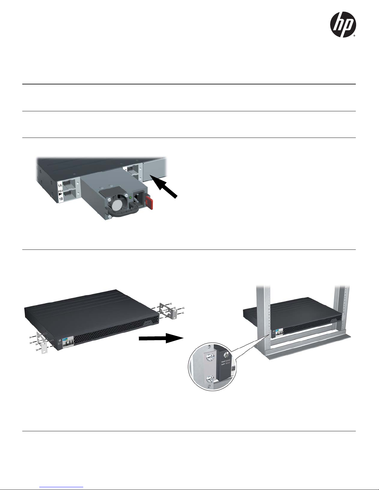
3. Install one or more compatible HP X331 or HP X332 power supplies into any of the slots in the 640 RPS/EPS.
Caution:
Incompatible Power Supplies are mechanically keyed to prevent accidental
insertion into the HP 640. Forcing an incompatible Power Supply into the HP
640 may cause permanent damage to the RPS/EPS. See “HP 640 RPS/EPS
Product Specifications” on page 5 for the identities of the compatible power
supplies.
When a compatible Power Supply is fully inserted, the maroon colored latch
will “click” into position to ensure that the Power Supply is correctly secured.
If the Power Supply is not easily pushed into the fully inserted position, reverify that a compatible Supply is being used, and re-attempt insertion.
HP produces a variety of Power Supplies in the form factor used in the HP 640
RPS/EPS. Some of these Power Supplies use voltages and power levels that
are not compatible with the HP 640. Verify that the Power Supply you have
chosen is compatible with the HP 640.
Use a power supply that is compatible with the HP 640.
4. Install the 640 RPS/EPS Hardware. Mount the 640 RPS/EPS in a rack or on a horizontal surface.
■ Rack Mounting: Use a #1 Phillips (cross-head) screwdriver to attach the accessory kit brackets to the 640 RPS/EPS
using the eight 8-mm M4 screws. Then use the four number 12-24 screws to secure the brackets to the rack.
Note: A rail kit is available for mounting the 640 RPS/EPS in 4-post racks and equipment cabinets by using the HP X410
Rail Kit (J9583A). For more information, see the HP 640 RPS/EPS Installation and Getting Started Guide, and the
documentation that is included with the kit.
1
Page 2
■ Horizontal Surface Mounting: Attach the four self-adhesive pads (included in the accessory kit) to the bottom
corners of the 640 RPS/EPS and place the unit on a secure horizontal surface.
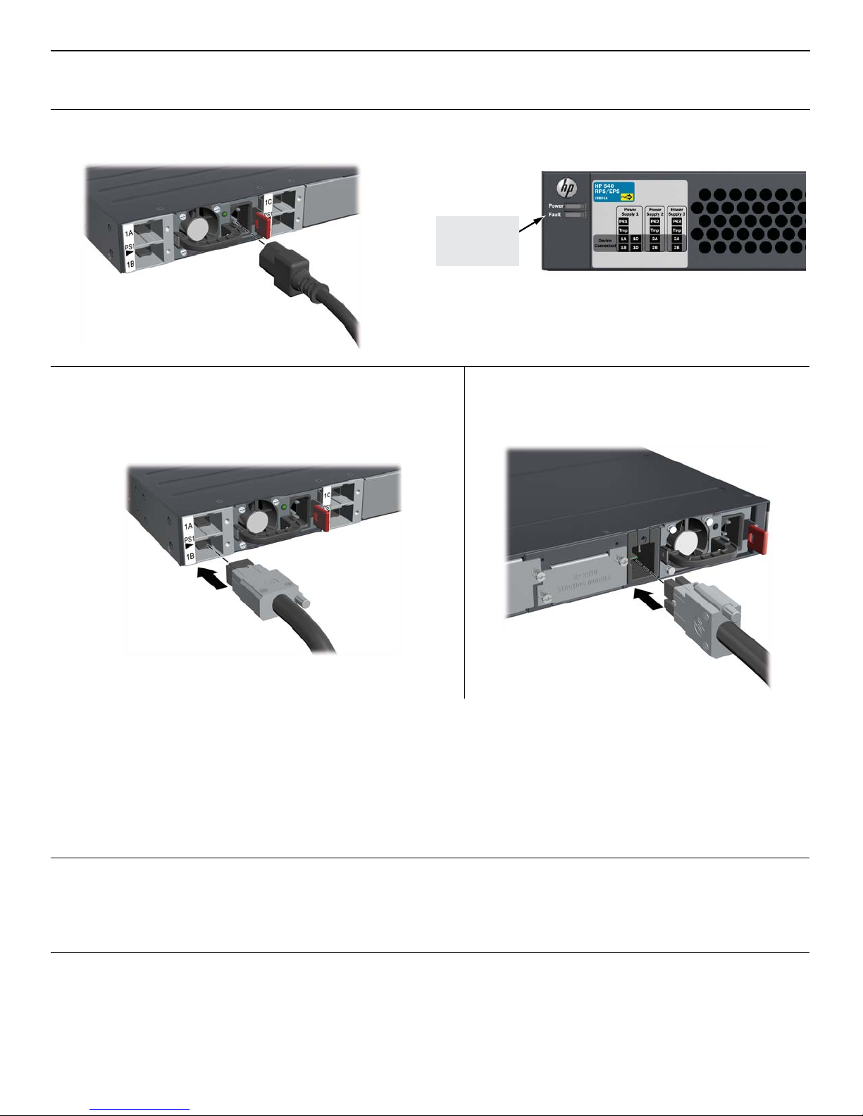
5. Power on the 640 RPS/EPS and verify that Self-Test completes normally. The 640 RPS/EPS does not contain a
power switch. It is powered on by connecting power through the AC power cord.
After Self-Test:
Power LED = On
Fault LED = Off
6. Connect RPS/EPS power cables.
Connect the RPS/EPS power cable into any of the connectors for
the power supply slot that you are using. Then hand tighten the
Then, also connect and secure the RPS/EPS power
cable to the switch.
retaining screw. Make sure that you do not overtighten the screw.
IMPORTANT: See the HP 640 RPS/EPS Installation and Getting Started Guide for supported RPS/EPS-toswitch power topologies and configuration information. Each of the power supplies installed in the 640 RPS/
EPS can provide redundant power to any one of multiple HP 2920 switches, and can also provide additional
PoE power for multiple HP 2920 PoE+ switches. But, failure to connect the devices together in a supported
topology can cause unexpected results.
For PoE/PoE+ information, see the HP Power over Ethernet (PoE/PoE+) Planning and Implementation Guide.
Both documents are on the HP web site at: www.hp.com/networking/support.
7. Confirm each RPS/EPS power cable connection. Check the LEDs on the front of the 640 RPS/EPS and the switch.
On the 640 RPS/EPS, the Device Connected LED for the connector that you have used (for example 1A) will be on solid green.
On the switch, the XPS LED will be on solid green. If either of the LEDs does not appear this way, then refer to the
“Troubleshooting” chapter in the switch or HP 640 RPS/EPS Installation and Getting Started Guide .
2
Page 3

HP 640 RPS/EPS Safety and Regulatory Information
To avoid personal injury or product damage when installing your640RPS/EPS,read the installation precautions and guidelines
below.
Installation Precautions
Warnings
■ Do not mount the 640 RPS/EPS on a wall.
■ Do not carry the 640 RPS/EPS by using the handles of any installed power supplies.
■ The rack or cabinet should be adequately secured to prevent it from becoming unstable, tilting or falling.
■ Devices installed in a rack or cabinet should be mounted as low as possible, with the heaviest devices at
the bottom and progressively lighter devices above.
Cautions
■ Ensure the power source circuits are properly grounded, then use the power cord supplied with the X331 or X332
power supplies that you install into the 640 RPS/EPS to connect to the AC power source.
■ If your installation requires a different power cord than the one supplied with the X331 or X332 power supplies, be
sure the cord is adequately sized for the power supply’s current requirements. In addition, be sure to use a power
cord displaying the mark of the safety agency that defines the regulations for power cords in your country/region.
The mark is your assurance that the power cord can be used safely with the power supplies.
■ When installing the 640 RPS/EPS, the AC outlet should be near the 640 RPS/EPS and should be easily accessible in
case the 640 RPS/EPS must be powered off.
■ Ensure the 640 RPS/EPS does not overload the power circuits, wiring, and over-current protection. To determine
the possibility of overloading the supply circuits, add together the ampere ratings of all devices installed on the same
circuit as the 640 RPS/EPS and compare the total with the rating limit for the circuit. The maximum ampere ratings
are usually printed on the devices near the AC power connectors.
■ Do not install the 640 RPS/EPS in an environment where the operating ambient temperature exceeds its specification.
■ Ensure the air flow around the 640 RPS/EPS is not restricted. Leave at least 7.6 cm (3 inches) for cooling. For the
air flow direction, see the Installation and Getting Started Guide for your product, located on the HP Networking
web site at www.hp.com/networking/support.
For additional Safety and Regulatory information, refer to the Safety and Regulatory documentation included with your
640 RPS/EPS, and to the safety and regulatory documentation on the HP web site at www.hp.com/support/Safety-Compliance-
EnterpriseProducts, and to the HP 640 RPS/EPS Installation and Getting Started Guide that can be found on the HP
Networking web site: www.hp.com/networking/support.
3
Page 4

HP 640 RPS/EPS and HP X331/X332 Power Supply Safety and Regulatory Statements
Safety Standards: EN60950-1:2006+A11:2009+A1:2010+A12:2011 / IEC60950-1:2005; Am1:2009;
CSA22.2 No. 60950-1-07 2nd; UL60950-1 2nd
China Altitude
Warning:
HP 640 RPS/EPS:
WARNING
FOR INDOOR USE ONLY. The 640 RPS/EPS, X331 and X332 power supplies, AC power cord, and all connected cables are
not designed for outdoor use.
4
Page 5

HP 640 RPS/EPS Product Specifications
Power Supplies
available for the
HP X331 165W
Power Supply (J9739A)
HP X332 575W
Power Supply (J9738A)
HP X332 1050W
Power Supply (J9737A)
HP 640 RPS/EPS:
Electrical:
AC voltage:
Maximum current:
Frequency range:
100 – 240 VAC
2.50 – 1.25 A
1
50/60 Hz
100 – 240 V
9.0 – 4.0 A
50/60 Hz
1
12.0 – 7.0 A
50/60 Hz
110 - 240 V
The power supplies automatically adjust to any voltage between 100 – 240 VAC
and either 50 or 60 Hz.
Environmental:
Operating
0°C to 55°C (32°F to 131°F)
Temperature:
Relative humidity: 15% to 95% at 40°C (104°F) (non-condensing)
Non-Operating
-40°C to 70°C (-40°F to 158°F)
Temperature:
Non-Operating
15% to 90% at 65°C (149°F) (non-condensing)
Relative humidity:
Maximum Operating
3.0 km (10,000 ft)
Altitude:
Non-Operating
4.6 km (15,000 ft)
Altitude:
1
These values represent the maximum current that these power supplies could draw. For typical values,
see the HP 640 RPS/EPS data sheet on the web site: www.hp.com/networking/support.
1
Power Cords
Use one of the following power cords:
Country/Region HP X331 165W and
HP X332 575W
Power Supplies
Argentina
Australia/New Zealand
Brazil
Chile
China
Continental Europe/South Korea
Denmark
India
Israel
Japan
Switzerland
South Africa
Taiwan
Philippines/Thailand
United Kingdom/Hong Kong/Singapore/Malaysia
United States/Canada/Mexico
1
The cords for the HP X332 1050W Power Supply supports a higher amperage and uses a
8120-6869
8121-0834
8121-1069
8120-6980
8120-8707
8120-6811
8120-6814
8121-0780
8121-1035
8120-4753
8120-6815
8120-6813
8121-0974
8121-0668
8120-6809
8121-0914
C15 connector.
HP X332 1050W
Power Supply
8121-1481
8121-1476
8121-1474
8121-1477
8121-1484
8121-1479
8121-1486
8121-1483
8121-1478
8120-5338
8121-1480
8121-1483
8121-1511
8121-1485
8121-1475
8121-0914
1
Japan Power Cord
Warning:
5
Page 6

Russia/Belarus/Kazakhstan/CEE Safety:
T
n
Product overview:
The HP 640 Redundant/External Power Supply Shelf (J9805A) is a unit that can house up to three HP X331 or X332 modular
power supplies (PSUs). The PSUs can supply redundant power to connected HP 2920 PoE and non-PoE Switches in the event
of an HP 2920 Switch internal power supply failure, and supply additional PoE power to the HP 2920 PoE Switches.
© Copyright 2015 Hewlett-Packard Company, L.P.
he information contained herein is subject to change without
otice.
Printed in China
April 2015
5998-4199
*5998-4199*
6
Page 7

 Loading...