

Page 1

ARMY
NAVY EE010-BJ-MMA-010/E154 DCDUAL
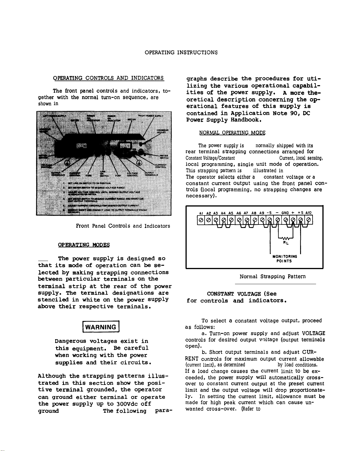
TM 11-6130-416-14
AIR FORCE
TECHNICAL MANUAL
T.O. 35C1-2-847-1
OPERATOR’S, ORGANIZATIONAL,
DIRECT SUPPORT AND GENERAL SUPPORT
MAINTENANCE MANUAL
FOR
POWER SUPPLY, DUAL DC
(H-P MODEL 6255A)
(NSN 6130-00-065-6811)
DEPARTMENTS OF THE ARMY, NAVY, AND AIR FORCE
31 JANUARY 1983
Page 2
TM 11-6130-416-14/EE010-BJ-MMA-010/E154 DCDUAL/T.O.35C1-2-847-1
SAFETY STEPS TO FOLLOW IF SOMEONE
IS THE VICTIM OF ELECTRICAL SHOCK
DO NOT TRY TO PULL OR GRAB THE lNDl-
VIDUAL
IF POSSIBLE, TURN OFF THE ELECTRICAL
POWER
IF YOU CANNOT TURN OFF THE ELECTRICAL
POWER, PULL, PUSH, OR LIFT THE PERSON TO
SAFETY USING A WOODEN POLE OR A ROPE
OR SOME OTHER INSULATING MATERIAL
SEND FOR HELP AS SOON AS POSSIBLE
AFTER THE INJURED PERSON IS FREE OF CONTACT WITH THE SOURCE OF ELECTRICAL
SHOCK, MOVE THE PERSON A SHORT
DISTANCE AWAY AND IMMEDIATELY START
ARTIFICIAL RESUSCITATION
Page 3

TM 11-6130-416-14/EE010-BJ-JMA-010/E154 DCDUAL/T.O. 35C1-2-847-1
INSERT LATEST CHANGED PAGES. DESTROY SUPERSEDED PAGES.
LIST OF EFFECTIVE PAGES
Dates of issue for original and changed pages are:
Original . . 0 . .
TOTAL NUMBER OF PAGES IN THIS PUBLICATION IS
Page
No.
Title. . . . . . . . . .
A. . . . . . . . . . . .
i
- vii. . . . . . . . .
viii Blank. . . . . . . .
1-1 - 1-4. . . . . . . .
2-1 - 2-2. . . . . . . .
3-1 - 3-8
4-1 - 4-6..............
5-1 - 5-23 . . . . . . . .
5-24 - Blank . . . . . . . .
A-1 . . . . . . . . . . .
A-2 Blank. . . . . . . .
B-1
- B-4 . . . . . . . .
C-1
- C-2. . . . . . . .
D-1 . . . . . . . . . . .
D-2 Blank. . . . . . . .
E-1 . . . . . . . . . . .
E-2 Blank.... . . . .
Index-1
Report of Errors. . . . .
FO-l
- Index-10. . . .
- FO-2 . . . . . . .
# Change
No. No.
0
0
0
0
0
0
0
0
0
0
0
0
0
0
0
0
0
0
0
0
0
Page
83 CONSISTING OF THE FOLLOWING:
# Change
No.
Page
No.
# Change
No.
# Zero in this column indicates an original page.
A
Page 4

TM 11-6130-416-14/EE010-BJ-MMA-010/E154 DCDUAL/T.O.35Cl-2-847-1
WARNING
DANGEROUS VOLTAGE
Is Used in the Operation of this Equipment
DEATH ON CONTACT
may result if personnel fail to observe safety precautions
Never work on electronic equipment unless there is another person
nearby who is familiar with the operation and hazards of the equipment
and who is competent in administering first aid.
is aided by operators, he must warn them about dangerous areas.
When the technician
Whenever possible, the power supply to the equipment must be shut off
before beginning work on the equipment. Take particular care to
ground every capacitor likely to hold a dangerous potential. When
working inside the equipment, after the power has been turned off,
always ground every part before touching it.
Be careful not to contact high-voltage connections when installing or
operating this equipment.
Whenever the nature of the operation permits, keep one hand away from
the equipment to reduce the hazard of current flowing through vital
organs of the body.
Do not be misled by the term “low voltage.” Potentials as low as 50
volts may cause death under adverse conditions.
B
Page 5

TM 11-6130-416-14/EE010-BJ-MMA-010/E154 DCDUAL/T.0.35Cl-2-847-1
Do not touch heat sinks or power transistors mounted on
heat sinks as they may be very hot after the instrument
has been on and operating.
CAUTION
Do not directly short out any of the large capacitors as
it places too much stress on them. Discharge capacitors
through a load resistor.
C/(D blank)
Page 6

Page 7

This manual contains copyright material reproduced by permission of the
Hewlett-Packard Company.
TM 11-6130-416-14
EE010-BJ-MMA-010/E154 DCDUAL
T.O.35C1-2-847-1
TECHNICAL MANUAL
NO. 11-6130-416-14
TECHNICAL MANUAL
EEO10-BJ-MMA-010/E154 DCDUAL
TECHNICAL ORDER
NO. 35CI-2-847-I
OPERATOR’S, ORGANIZATIONAL, DIRECT SUPPORT, AND GENERAL SUPPORT
REPORTING ERRORS AND RECOMMENDING IMPROVEMENTS
DEPARTMENTS OF THE ARMY,
THE NAVY,
AND THE AIR FORCE
Washington, DC, 31 January 1983
MAINTENANCE MANUAL
FOR
POWER SUPPLY, DUAL DC
(H-P Model 6255A)
(NSN 6130-00-065-6811)
You can help improve this manual.
If you find any mistakes or
if you know of a way to improve the procedures, please let us
know.
Publications and Blank
of
Communications-Electronics Command and Fort Monmouth,
DRSEL-ME-MP, Fort Monmouth,
Mail your letter, DA Form 2028 (Recommended Changes to
this
manual
Forms),
direct to:
or DA Form 2028-2 located in back
Commander, US
Army
ATTN:
NJ 07703.
For Air Force, submit AFTO Form 22 (Technical Order System
Publication Improvement Report and Reply) in accordance with
paragraph 6-5, Section VI, T.O. 00-5-1. Forward direct to prime
ALC/MST.
For Navy, mail comments to the Commander, Naval Electronics
Systems Command, ATTN:
ELEX 8122, Washington, DC 20360.
In either case, a reply will be furnished direct to you.
This manual is an authentication of the manufacturer’s commercial literature which,
through usage, has been found to cover the data required to operate and maintain
this equipment.
specifications and AR
Since the manual was not prepared in accordance with military
310-3,
the format has not been structured to consider levels
of maintenance.
i
Page 8

TM 11-6130-416-14/EE010-BJ-MMA-010/E154 DCDUAL/T.O35C1-2-847-1
TABLE OF CONTENTS
Section
I
GENERAL INFORMATION . . . . . . . . . . . .1-1
1-A.1
1-A.3
1-A.4
1-A.6
1-A.8
Page No.
Scope
1-1
Index of Publications 1-1
Army
Air Force
Maintenance Forms,
1-1
1-1
1-1
Section
3-3
3-5
3-7
3-9
3-11
3-14
Operating Modes
Normal Operating Mode
Constant Voltage
Constant Current
Connecting Load
Operation of Supply
Records and Reports
1-A.9
Reports of Maintenance
3-16
Optional Operational
and Unsatisfactory
1-A.11
1-A.13
1-A.15
Equipment
1-1
Report of Packaging
and Handling
Deficiencies
1-1
Discrepancy in Shipment
Report (DISREP)
(SF 361)
1-1
Reporting Equipment
3-17
3-24
3-30
3-35
3-39
3-42
Remote Programming,
Remote Programming
Parallel Operation
Auto-Tracking
Improvement
1-1
1-1
1-1
1-2
1-2
1-2
1-3
1-3
1-3
3-45
3-46
3-48
3-51
3-53
3-55
IV PRINCIPLES OF OPERATION . . . . . . . ...4-1
4-1
4-5
4-8
4-9
1-A.18
l-A.20
1-A.22
1-A.24
1-1
1-6
1-8
1-10
1-13
Recommendations (EIR)
Air Force
Navy
Administrative
Storage
Destruction Of Army
Electronics Materiel
Description
Specifications
Options
Instrument Identifica-
tion
Ordering Additional
Manuals
4-14
II
INSTALLATION
2-1
2-3
2-5
2-7
2-9
Initial Inspection
Mechanical Check
Electrical Check
Installation Data
Location
2-11 Rack Mounting
2-13 Input Power Requirements 2-1
2-15 Connections for 230 Volt
Operation
2-17 Power Cable
2-20 Repackaging for Shipment 2-2
. . . . . . . . . . . . . . . . . . .2-1
4-16
2-1
2-1
4-20
2-1
2-1
2-1
4-25
4-28
2-1
4-31
4-34
2-1
2-2
V MAINTENANCE . . . . . . . . . . . . . . . . . . . . .5-1
5-1
5-3
III OPERATING INSTRUCTIONS . . . . . . . . . . .3-1
3-1
Operating Controls and
Indicators
3-1
5-8
Page No.
3-1
3-1
3-1
3-2
3-2
Beyond Rated Output
Modes
Constant Voltage
Constant Current
Remote Sensing
Series Operation
3-2
3-2
3-2
3-3
3-4
3-4
3-5
Operation
3-6
Special Operating Considerations
Pulse Loading
Output Capacitance
Reverse Voltage Loading
Reverse Current Loading
3-6
3-6
3-6
3-7
3-7
Overvoltage Protection
Crowbar
3-7
Overall Block Diagram
Discussion 4-1
Simplified Schematic
4-2
Detailed Circuit Analysis 4-3
Feedback Loop
Series Regulator
4-3
4-3
Constant Voltage Input
Circuit
4-3
Constant Current Input
Circuit 4-4
Voltage Clamp Circuit
4-4
Mixer and Error
Amplifiers
Reference Circuit
Meter Circuit
Introduction
4-4
4-5
4-5
5-1
General Measurement
Techniques
5-1
Test Equipment
Required
5-2
ii
Page 9

TM 11-6130-416-14/EE010-BJ-NMA-010/E154 DCDUAL/T.O.35Cl-2-847-1
TABLE OF CONTENTS (CONTINUED)
Section
5-10
5-12
5-34
5-39
5-41
5-46
5-47A.1
5-47A.3
5-47A.5
5-47A.7
5-47A.9
5-47A.11
5-47A.13
5-47A.15
5-47A.17
5-47A.19
5-47A.21
5-47A.23
5-47A.25
5-47A.27
Page No.
Performance Test
Constant Voltage
Tests
Constant Current
(CC) Tests
Troubleshooting
Trouble Analysis
Repair and Replace-
ment
Fuse Replacement
Cover Removal
Power Cable
Replacement
Switch S1
Replacement
Transformer T1
Replacement
Overvoltage
Protection Crowbar
P.C. Board Replace-
ment
Main Left P.C.
Board Replacement
(Viewed from Front
of Power Supply)
Main Right P.C.
Board Replacement
(Viewed from Front
of Power Supply)
Capacitator C14
Replacement
Capacitors C5, C6
Replacement
Power Transistor Q4,
Q6, Replacement
Power Transistor Q7,
Replacement
Transistor Q3
Replacement
Voltage/Current
Programming Control
Replacement
5-2
5-2
5-8
5-9
5-9
5-14
5-15
5-15
5-17
5-17
5-17
5-18
5-18
5-18
5-19
5-19
5-19
5-20
5-20
5-20
Section
Page No.
5-47A.29 Silicon Rectifier
CR19 Replacement
5-47A.31
Meter Switch S2
Replacement
5-47A.33 Meter Replacement
5-20
5-21
5-21
5-47A.35 Shunt Resistor
(R81, R82, or R83)
Replacement
5-21
5-47A.37 Fuse Holder Assembly
Replacement
5-21
5-47A.39 Neon Lamp DS1
Replacement
5-21
5-47A.41 Crowbar Adjust
Potentiometer R5
Replacement
5-22
5-48 Adjustment and
Calibration
5-50 Meter Zero.
5-52 Voltmeter Tracking
5-54 Ammeter Tracking
5-22
5-22
5-22
5-22
5-56 Constant Voltage
Programming Current
5-22
5-59 Constant Current
Programming Current
5-23
5-62 Reference Circuit
Adjustments
5-23
5-64 Constant Voltage
Transient Response
5-23
VI REPLACEABLE PARTS . . . . . . . . . . . . . . .6-1
6-1
6-4
Introduction
Ordering Information
6-1
6-1
APPENDIX A . . . . . . . . . . . . . . . . . . . . . . . . . . A-1
APPENDIX B . . . . . . . . . . . . . . . . . . . . . . . . B-1
APPENDIX C . . . . . . . . . . . . . . . . . . . . . . . . C-1
APPENDIX D . . . . . . . . . . . . . . . . . . . . . . . D-1
APPENDIX E . . . . . . . . . . . . . . . . . . . . . . . E-1
INDEX
Index 1
iii
Page 10

Figure
TM 11-6130-416-14/EE010-BJ-MMA-010/E154 DCDUAL/T.O.35C1-2-847-1
LIST OF ILLUSTRATIONS
Page No.
Figure
Page No.
1-1
2-1
3-1
3-2
3-3
3-4
3-5
3-6
3-7
3-8
3-9
3-10
3-11
3-12
3-13
4-1
4-2
DC Power Supply
Primary Connections
Front Panel Control and
Indicators
Normal Strapping Pattern
Remote Resistance
Programming(Constant
Voltage)
Remote Voltage
Programming (Constant
Voltage)
Remote Resistance
Programming (Constant
Current)
Remote Voltage
Programming (Constant
Current)
Remote Sensing
Normal Series Connections
Auto-Series, Two and
Three Units
Normal Parallel ,
Connections
Auto-Parallel, Two and
Three Units
Auto-Tracking, Two and
Three Units
Model 6255A and 6289A
Overvoltage Protection
Crowbar
Overall Block
Diagram
Simplified Schematic
v
2-1
3-1
3-1
3-2
3-3
3-3
3-3
3-4
3-4
3-5
3-5
3-5
3-6
3-8
4-1
4-2
4-3
4-4
5-1
5-2
5-3
5-4
5-5
5-6
5-7
5-8
5-9
5-10
5-11
5-12
5-13
5-14
FO-1
FO-2
Voltmeter Connections,
Simplified Schematic
Ammeter Connections,
Simplified Schematic
Front Panel Terminal
Connections
Output Current
Measurement Technique
Differential Voltmeter
Substitute Test Setup
Output Current, Test
Setup
Load Regulation, Constant
Voltage Test Setup
CV Ripple and Noise Test
Setup
CV Noise Spike Test Setup 5-6
Transient Response
Test Setup
Transient Response,
Waveforms
CV Programming, Speed,
Test Setup
Output Impedance,
Test Setup
CC Ripple and Noise Test
Setup
Servicing Printed Wiring
Boards
Model 6255A Modular
Cabinet
6255A Schematic
Parts Location/Intercon-
nection Diagram
4-5
4-5
5-1
5-1
5-2
5-2
5-4
5-4
5-6
5-6
5-7
5-7
5-8
5-13
5-16
Table
5-1
5-2
5-4
5-5
iv
1-1
5-3
LIST OF TABLES
Page No.
Specifications
Test Equipment Required 5-3
Common Troubles
Reference, Bias, and
Filtered DC
Troubleshooting
Low Output Voltage
Troubleshooting
High Output Voltage
Troubleshooting
1-4
5-9
5-11
5-11
5-12
Table
5-6
5-7
5-8
Selected Semiconductor
Characteristics
Checks and Adjustments
After Replacement of
Semiconductor Devices
Calibration and
Adjustment Summary
Page No.
5-14
5-14
5-15
Page 11
TM 11-6130-416-14/EE010-BJ-MMA-010/E154 DCDUAL/T.0.35C1-2-847-1
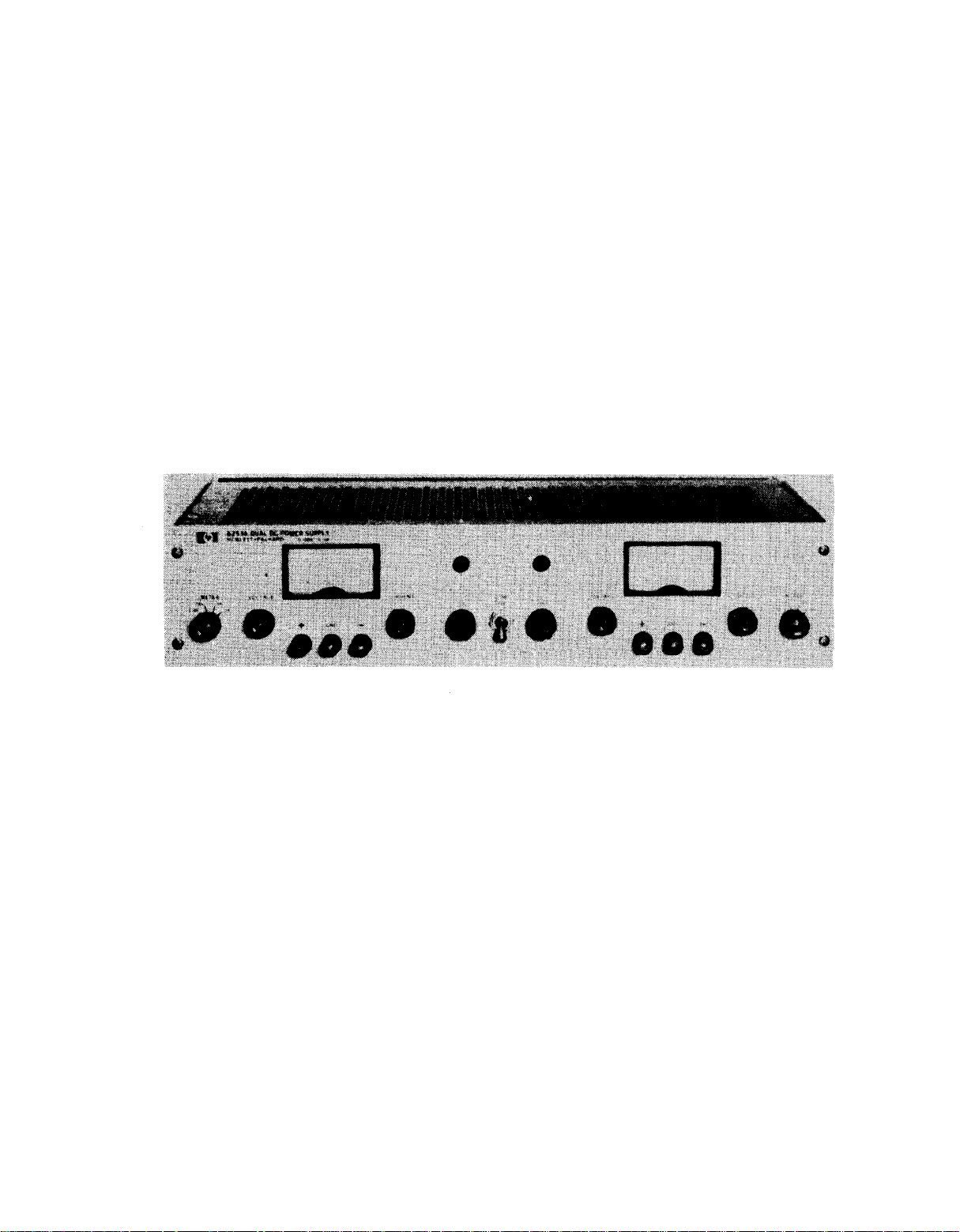
Figure 1-1.
Typical DPR Series DC Power Supply
v/(vi blank)
Page 12

Page 13
TM 11-6130-416-14/EE010-BJ-MMA-010/E154 DCDUAL/T.0.35C1-2-847-1
SECTION I
GENERAL INFORMATION
1-A.1
1-A.2
6255A Dual DC Power Supply with Option
11 Overvoltage Protection Crowbar Circuit (power supply serial numbers
2012A-4996 and up). Responsibilities
for all levels of maintenance are specified by the Maintenance Allocation
Chart (MAC) contained in
1-A.3
1-A.4
1-A.5
PAM 310-1 to determine whether there
are new editions, changes or additional
publications pertaining to the equip-
ment.
1-A.6
1-A.7
cal Index and Requirements Table
(NIRT).
1-A.8
REPORTS
1-A.9
UNSATISFACTORY EQUIPMENT
1-A.10
and procedures used for equipment main-
tenance will be those prescribed by
38-750,
System (Army).
will use AFM 66-1 for maintenance re-
porting and T.O. 00-35D54 for unsatis-
factory equipment reporting. Navy personnel will report maintenance performed utilizing the Maintenance Data
Collection Subsystem (MDCS) IAW
OPNAVINST 4790.2, Vol 3, and unsatis-
factory material/conditions (UR
submissions) IAW OPNAVINST 4790.2, Vol
2,
chapter 17.
SCOPE
This manual describes the Model
Appendix B.
INDEX OF PUBLICATIONS
ARMY
Refer to the latest issue of DA
AIR
FORCE
Use T.O. 0.1-31 Series Numeri-
MAINTENANCE FORMS, RECORDS AND
REPORTS
Department of the Army forms
The Army Maintenance Management
OF
MAINTENANCE AND
Air
Force personnel
TM
1-A.12
(Report of Discrepancy (ROD) as pre-
scribed in AR 735-11-2/DLAR 4140.55/
NAVMATINST 4355.73/AFR 400-54/MCO
4430.3E.
1-A.13
(DISREP) (SF
1-A.14
ancy in Shipment Report (DISREP) (SF
361) as prescribed in AR 55-38/
NAVSUPINST 4610.33B/AFR 75-18/MCO
P4610.19C/DLAR 4500.15.1-4.
1-A.15
IMPROVEMENT RECOMMENDATIONS) (EIR)
1-A.16
1-A.17
needs improvement, let us know.
us an EIR.
only one who can tell us what is not
liked about your equipment. Let us
know why you do not like the design.
Tell us why a procedure is hard to per-
form.
Deficiency Report).
der, US Army Communications-Electronics
Command and Fort Monmouth, ATTN:
DRSEL-ME-MP, Fort Monmouth,
We will send you a
1-A.18
1-A.19
encouraged to submit EIRs in accordance
with AFM 900-4.
1-A.20
1-A.21
to submit EIRs through their local
Beneficial Suggestion Program.
1-A.22
Fill out and forward SD 364
DISCREPANCY IN SHIPMENT REPORT
361)
Fill out and forward Discrep-
REPORTING EQUIPMENT
ARMY
If the Power Supply, Dual DC
Send
You, the user, are the
Put it on an SF 368 (Quality
Mail it to Comman-
NJ
07003.
reply
AIR FORCE
Air Force personnel are
NAVY
Navy personnel are encouraged
ADMINISTRATIVE STORAGE
1-A.11
HANDLING
REPORT OF PACKAGING AND
DEFICIENCIES
1-1
1-A.23
Refer to
TM 11-5805-683-12
or
Page 14
TM 11-6130-416-14/EE010-BJ-MMA-010/E154 DCDUAL/T.O.35C1-2-847-1
TM 11-5805-681-12,
Administrative storage of equip-
age.
ment issued to and used by Army activi-
ties will have preventive maintenance
performed in accordance with the Pre-
ventive Maintenance Checks and Services
(PMCS) procedure listed before storing.
When removing the equipment from administrative storage,the PMCS should be
performed to assure operational readi-
ness.
equipment for shipment or limited stor-
age are also covered.
90-1 if
charts.
1-A.24
ELETRONICS
1-A.25
ics materiel to prevent enemy use shall
be in accordance with
Disassembly and repacking of
there are no published PM
DESTRUCTION OF ARMY
MATERIEL
Destruction of Army electron-
Administrative Stor-
Refer to
TM 750-244-2.
TM 749-
1-3
Each supply has both
Either the positive or negative output terminal may
be grounded or the power supply can be operated
floating
at up to a
1-4
and operating controls.
tiple range type and can measure output voltage or
current. The voltage or current
by the applicable METER switch
1-5 TWO
the rear of the unit allow ease in adapting to the
many operational capabilities of the power supply.
A
below:
from a remote location by means of an external
voltage source or resistance.
Each section has its own front panel meter
sets of programming terminals located at
brief description
a.
Remote
The power supply maybe programmed
b. Remote Sensing
front
maximum
Programming
and rear
of
300 volts off
The meters are of the mul-
ranges
on
of these capabilities
terminals.
are selected
the front panel.
ground.
is
given
1-1
DESCRIPTION
1-2
completely transistorized and suitable
for either rack or bench operation. It
is a dual supply consisting of two independently controlled sections; both
identical to each other.
will be referred to as the left and
right side power supplies as viewed from
front of unit.
regulated,Constant Voltage/Constant
Current source that will furnish full
rated output
rated output current or can be continuously adjusted throughout either output
range.
can be used to establish the output cur-
rent limit
when the supply is used as a constant
voltage source and the VOLTAGE control(s)
voltage limit
is used as a constant current source.
Each section will automatically crossover from constant voltage to constant
current operation and vice versa if the
output current or voltage exceeds these
preset limits.
This power supply,
Each section is a well-
voltage at
The front panel CURRENT controls
(overload or
can be
used to establish the
(ceiling) when
Figure 1-1,
These sections
the maximum
short circuit)
the supply
is
The degradation in regulation which
would occur
in
the
supply in the remote sensing mode of operation.
c.
when a higher output voltage is required in the
voltage mode of operation or
compliance
of operation. Auto-Series operation permits one
knob control of the total output voltage
“master"
parallel
rent capability
permits one knob control
from
“master” supply, having control
“slave” supplies that furnish various voltages for
a system.
1-6
1-7
supply.
d. Parallel and Auto-Parallel Operation
a
e.
SPECIFICATIONS
Detailed specifications
at the
load leads can be reduced by using the power
Series and Auto-Series Operation
Power supplies maybe used in series
is
required in
The power supply may be operated
with a
is
required. Auto-Parallel
“master” supply.
Auto-Tracking
The power supply maybe used
load because of the voltage drop
when
the
similar unit when greater output cur-
of
the total output current
for
greater voltage
constant current mode
from a
in
operation
as
over
one (or more)
the power supply
a
1-2
Page 15
TM 11-6130-416-14/EE010-BJ-MM-010/E154 DCDUAL/T.O.35C1-2-847-1
are given in
1-8
1-9
ard instrument that are requested by the customer.
The following options are available for the instru-
ment covered by this manual. Where necessary,
detailed coverage of the options is included through-
out the manual.
Option No.
Table 1-1.
NOTE
Since both sections of this supply
are identical, only one section will
be discussed throughout the remain-
ing portions of this manual. All
descriptions, illustrations,
and adjustments apply equally to
both sections of the supply.
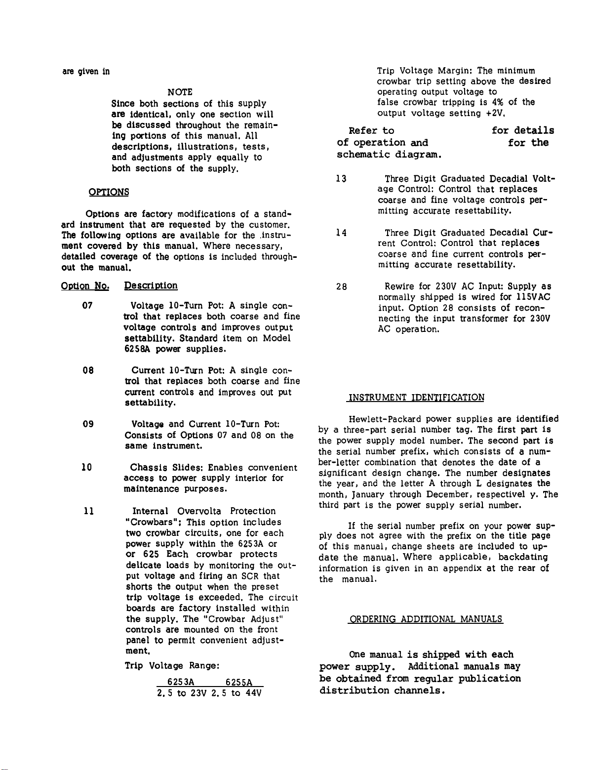
OPTIONS
Options are factory modifications
Description
07
Voltage 10-Turn Pot: A single control that replaces both coarse and fine
voltage controls and improves output
settability.
6258A power supplies.
Standard item on Model
tests,
of a
stand-
Trip Voltage Margin: The minimum
crowbar trip setting above the desired
operating output voltage to
false crowbar tripping is 4% of the
output voltage setting +2V.
Refer to
of operation and
schematic diagram.
13
14 Three Digit Graduated Decadial Cur-
28
Paragraph 3-55
Figure 3-13
Three Digit Graduated Decadial Volt-
age Control: Control that replaces
coarse and fine voltage controls permitting accurate resettability.
rent Control: Control that replaces
coarse and fine current controls permitting accurate resettability.
Rewire for 230V AC Input: Supply as
normally shipped is wired for 115VAC
input. Option 28 consists of reconnecting the input transformer for 230V
AC operation.
prevent
for details
for the
08
09
10
11
Current 10-Turn Pot: A single control that replaces both coarse and fine
current controls and improves out put
settability.
Voltage and Current 10-Turn Pot:
Consists of Options 07 and 08 on the
same instrument.
Chassis Slides: Enables convenient
access to power supply interior for
maintenance purposes.
Internal Overvoltage Protection
“Crowbars”: This option includes
two crowbar circuits, one for each
power supply within the 6253A or
or 6255A. Each crowbar protects
delicate loads by monitoring the output voltage and firing an SCR that
shorts the output when the preset
trip voltage is exceeded. The circuit
boards are factory installed within
the supply. The “Crowbar Adjust”
controls are mounted on the front
panel to permit convenient adjust-
ment.
Trip Voltage Range:
6253A
2.5 to 23V 2.5 to 44V
6255A
1-10
1-11
by a three-part serial number tag. The first part is
the power supply model number. The second part is
the serial number prefix, which consists of a number-letter combination that denotes the date of a
significant design change. The number designates
the year, and the letter A through L designates the
month, January through December, respective y. The
third part is the power supply serial number.
1-12 If
ply does not agree with the prefix on the title page
of this manual, change sheets are included to up-
date the manual.
information is given in an appendix at the rear of
the manual.
power supply.
INSTRUMENT IDENTIFICATION
Hewlett-Packard power supplies are identified
the serial number prefix on your power sup-
Where applicable, backdating
1-13
be obtained from regular publication
distribution channels.
ORDERING ADDITIONAL MANUALS
1-14
One manual is shipped with each
Additional manuals may
1-3
Page 16
TM 11-6130-416-14/EE010-BJ-MMA-010/E154 DCDUAL/T.0035C1-2-847-1
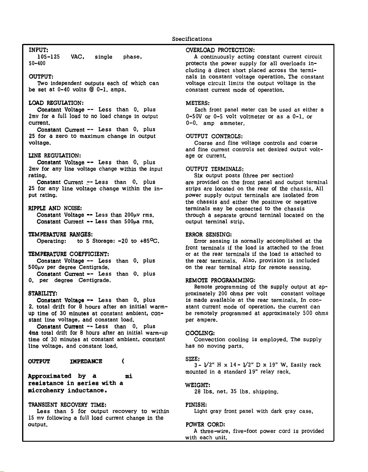
Table 1-1. Specifications
INPUT:
105-125/210-250
50-400
OUTPUT:
Two independent outputs each of which can
be set at 0-40 volts @ 0-1.5 amps.
LOAD REGULATION:
Constant Voltage
2mv for a full load to no load change in output
current.
Constant Current
250µa for a zero to maximum change in output
voltage.
LINE REGULATION:
Constant Voltage
2mv for any line voltage change within the input
rating.
Constant Current -250µa for any line voltage change within the input rating.
RIPPLE AND NOISE:
Constant Voltage
Constant Current --
cps.
VAC, single phase,
-- Less than 0.01% plus
-- Less than 0.01% plus
-- Less than 0.01% plus
Less than 0.01% plus
-- Less than 200µv rms.
Less than 500µa rms.
OVERLOAD PROTECTION:
A continuously acting constant current circuit
protects the power supply for all overloads including a direct short placed across the terminals in constant voltage operation. The constant
voltage circuit limits the output voltage in the
constant current mode of operation.
METERS:
Each front panel meter can be used as either a
0-50V or 0-5 volt voltmeter or as a 0-1.8A or
0-0.18 amp ammeter.
OUTPUT CONTROLS:
Coarse and fine voltage controls and coarse
and fine current controls set desired output voltage or current.
OUTPUT TERMINALS:
Six output posts (three per section)
are provided on the front panel and output terminal
strips are located on the rear of the chassis. All
power supply output terminals are isolated from
the chassis and either the positive or negative
terminals may be connected to the chassis
through a separate ground terminal located on the
output terminal strip.
TEMPERATURE RANGES:
Operating:
TEMPERATURE COEFFICIENT:
Constant Voltage
500µv per degree Centigrade.
Constant Current
0.8ma per degree Centigrade.
STABILITY:
Constant Voltage
2.5mv total drift for 8 hours after an initial warmup time of 30 minutes at constant ambient, constant line voltage, and constant load.
Constant Current -4ma total drift for 8 hours after an initial warm-up
time of 30 minutes at constant ambient, constant
line voltage, and constant load.
OUTPUT
Approximated by a
resistance in series with a
microhenry inductance.
TRANSIENT RECOVERY TIME:
Less than 50µsec
15 mv following a full load current change in the
output.
0 to
50°C.
Storage: -20 to +85°C.
-- Less than 0.02% plus
-- Less than 0.02% plus
-- Less than 0.10% plus
Less than 0.10% plus
IMPEDANCE
for output recovery to within
10
(TYPICAL):
milliohm
1
ERROR SENSING:
Error sensing is normally accomplished at the
front terminals if the load is attached to the front
or at the rear terminals if the load is attached to
the rear terminals.
on the rear terminal strip for remote sensing.
REMOTE PROGRAMMING:
Remote programming of the supply output at ap-
proximately 200 ohms per volt
is made available at the rear terminals. In con-
stant current mode of operation, the current can
be remotely programmed at approximately 500 ohms
per ampere.
COOLING:
Convection cooling is employed. The supply
has no moving parts.
SIZE:
3- 1/2" H x 14- 1/2"
mounted in a standard 19” relay rack.
WEIGHT:
28 lbs. net, 35 lbs. shipping.
FINISH:
Light gray front panel with dark gray case.
POWER CORD:
A three-wire, five-foot power cord is provided
with each unit.
Also, provision is included
in
constant voltage
D x
19” W. Easily rack
1-4
Page 17
TM 11-6130-416-14/EE010-BJ-MMA-010/E154 DCDUAL/T.O.35C1-2-847-1
SECTION II
INSTALLATION
2-1
INITIAL INSPECTION
2-2
Before shipment, this instrument was inspected and found to be free of mechanical and electrical defects. As soon as the instrument is un-
packed, inspect for any damage that may have oc-
curred in transit. Save all packing materials until
the inspection is completed.
2-3
MECHANICAL CHECK
2-4
This check should confirm that there are no
broken knobs or connectors, that the cabinet and
panel surfaces are free of dents and scratches,
and that the meter is not scratched or cracked.
either
power
tory, is wired for 115 volt operation. The input
power required when operated from a 115 volt 60
cycle power source at full load is 235 watts and
2.6 amperes.
2-15
a nominal 115 volt or 230 volt 50-400 cycle
source. The unit, as shipped from the fac-
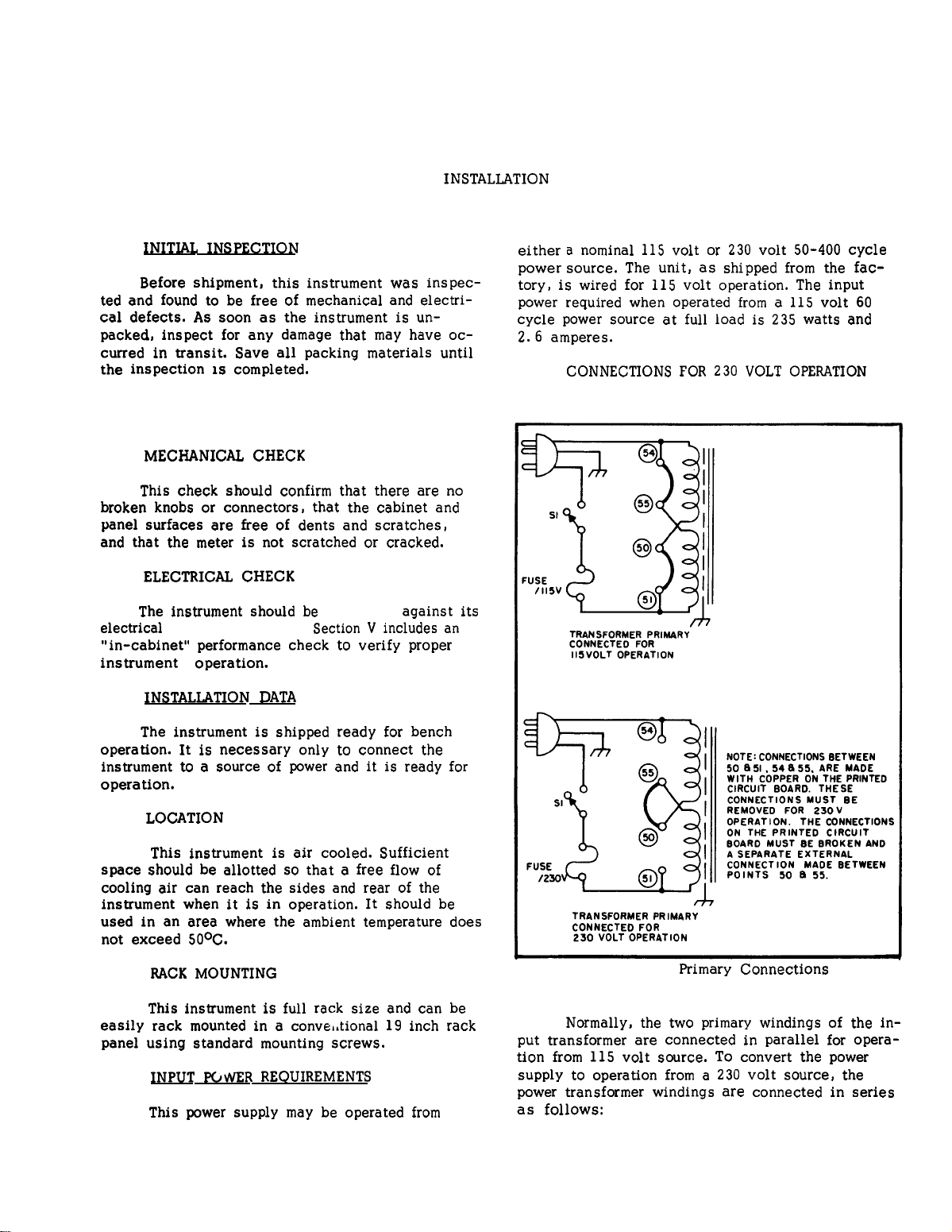
CONNECTIONS FOR 230 VOLT OPERATION
(Figure 2-1)
2-5
ELECTRICAL CHECK
2-6
The instrument should be
electrical
“in-cabinet” performance check to verify proper
instrument operation.
2-7
2-8
operation. It is necessary only to connect the
instrument to a source of power and it is ready for
operation.
2-9
2-10
space should be allotted so that a free flow of
cooling air can reach the sides and rear of the
instrument when it is in operation. It should be
used in an area where the ambient temperature does
not exceed 50°C.
2-11
2-12
easily rack mounted in a conventional 19 inch rack
panel using standard mounting screws.
2-13
2-14
specifications.
INSTALLATION DATA
The instrument is shipped ready for bench
LOCATION
This instrument is air cooled. Sufficient
RACK MOUNTING
This instrument is full rack size and can be
INPUT POWER REQUIREMENTS
This power supply may be operated from
checked
Section V includes an
against its
Figure 2-1.
2-16
put transformer are connected in parallel for operation from 115 volt source. To convert the power
power transformer windings are connected in series
as follows:
Normally, the two primary windings of the in-
supply to operation from a 230 volt source, the
Primary Connections
2-1
Page 18
TM 11-6130-416-14/EE010-BJ-MMA-010/E154 DCDUAL/T.O.35C1-2-847-1
a.
Unplug the line cord and remove the
unit covers.
b.
Break the copper between 54 and 55 and
also between 50 and 51 on the printed circuit
board. These are shown in
Figure 2-1,
and are
labeled on copper side of printed circuit board.
c.
Add strap between 50 and 55.
d.
Replace existing fuse with 2 ampere,
230 volt fuse. Return unit to case and operate
cable three-prong connector is the ground connection.
2-19 To
operating the instrument from a two-contact outlet,
use a three-prong to two-prong adapter and connect the green lead on the adapter to ground.
2-20
REPACKAGING FOR SHIPMENT
normally.
2-21 To
2-17
POWER CABLE
it is recommended that the package designed for
the instrument be used. The original packaging
2-18 To
protect
operating
personnel,the
National
material is reusable.
Electrical Manufacturers Association(NEMA)recommends that the instrument panel and cabinet be
grounded.
This instrument is equipped with a
three conductor power cable. The third conductor
is the ground conductor and when the cable is
plugged into an appropriate receptacle, the instrument is grounded. The offset pin on the power
preserve the protection feature when
insure safe shipment of the instrument,
2-2
Page 19
TM ll-6130-416-14/EE010-BJ-MMA-010/E154 DCDUAL/T.O.35C1-2-847-1
OPERATING INSTRUCTIONS
3-1
OPERATING CONTROLS
3-2
The front panel controls and indicators, together with the normal turn-on sequence, are
shown in
Figure 3-1.
AND
INDICATORS
SECTION III
graphs describe the procedures for uti-
lizing the various operational capabilities of the power supply.
oretical description concerning the operational features of this supply is
contained in Application Note 90, DC
Power Supply Handbook.
3-5
NORMAL
3-6
The power supply
rear terminal strapping connections arranged for
Constant
local programming, single unit mode of operation.
This strapping pattern
The operator selects either
constant current output using the front panel controls (local programming, no strapping changes are
necessary).
OPERATING MODE
is
normally shipped with
Voltage/Constant
is
illustrated
a
constant voltage or
A more the-
its
Current,
local sensing,
in Figure 3-2.
a
Figure 3-1.
3-3
3-4
that its mode of operation can be se-
lected by making strapping connections
between particular terminals on the
terminal strip at the rear of the power
supply. The terminal designations are
stenciled in white on the power supply
above their respective terminals.
Although the strapping patterns illus-
trated in this section show the positive terminal grounded, the operator
can ground either terminal or operate
the power supply up to 300vdc off
ground(floating).
OPERATING MODES
The power supply is designed so
Dangerous voltages exist in
this equipment.
when working with the power
supplies and their circuits.
Front Panel Controls and Indicators
Be careful
The following
para-
Figure 3-2.
3-7
for
3-8
as follows:
controls for desired output voltage (output terminals
open).
RENT controls for maximum output current allowable
(current
If a load change causes the current limit to be exceeded, the power supply will automatically crossover to constant current output at the preset current
limit and the output voltage will drop proportionately.
made for high peak current which can cause un-
wanted cross-over.
CONSTANT VOLTAGE (See
controls and indicators.)
To select a constant voltage output, proceed
a. Turn-on power supply and adjust VOLTAGE
b. Short output terminals and adjust CUR-
limit),
as
In setting the current limit, allowance must be
Normal Strapping Pattern
Figure 3-1
determined by
(Refer to
Paragraph 3-46.)
load conditions.
3-1
Page 20
TM 11-6130-416-14/EE010-BJ-MMA-010/E154 DCDUAL/T.O.351-2-847-1
3-9
for controls and indicators.)
3-10
as follows:
RENT controls for desired output current.
controls for maximum output voltage allowable (volt-
age limit), as determined by load conditions. If a
load change causes the voltage limit to be exceeded,
the power supply will automatically
constant voltage output at the preset voltage limit
and the output current will drop proportionately.
setting the voltage limit, allowance must be made
for high peak voltages which can cause unwanted
crossover.
3-11
for output terminals.)
3-12
supply output terminals using separate pairs of connecting wires. This will minimize mutual coupling
effects between loads and will retain full advantage
of the low output impedance of the power supply.
Each pair of connecting wires should be as short as
possible and twisted or shielded to reduce noise
pickup. (If shield is used, connect one end to
power supply ground terminal and leave the other
end unconnected.)
CONSTANT CURRENT (See
To select a
a. Short output terminals and adjust CUR-
b. Open output terminals and adjust VOLTAGE
(Refer to
CONNECTING LOAD (See
Each load should be connected to the power
constant
Paragraph 3-46.)
Figure 3-1
current output, proceed
y
crossover to
Figure 3-1
In
source can be used for the programming device.
The wires connecting the programming terminals of
the supply to the remote programming device should
be twisted or shielded to reduce noise pick-up.
The VOLTAGE controls on the front panel are disabled according to the following procedures.
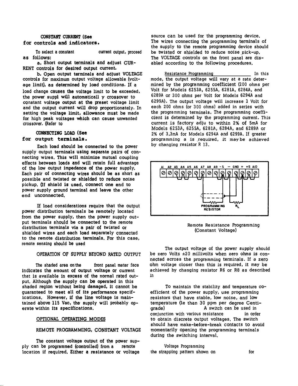
3-19
Resistance Programming
mode, the output voltage will vary at a rate determined by the programming coefficient (200 ohms per
Volt for Models 6253A, 6255A, 6281A, 6284A, and
6289A or 300 ohms per Volt for Models 6294A and
6299A). The output voltage will increase 1 Volt for
each 200 ohms (or 300 ohms) added in series with
the programming terminals. The programming coefficient is determined by the programming current. This
current is factory adjusted
Models 6253A, 6255A, 6281A, 6284A, and 6289A or
2% of 3.3mA for Models 6294A and 6299A. If greater
programming accuracy
by changing resistor-R 13.
is
(Figure 3-3). In
to
within 2% of 5mA for
required, it maybe achieved
this
3-13 If
power distribution
from the power supply, then the power supply out-
put terminals should be connected to the remote
distribution
shielded wires and each load separately connected
to the remote distribution
remote sensing should be used
3-14
3-15
indicates the amount of output voltage or current
that is available in excess of the normal rated output. Although the supply can be operated in this
shaded region without being damaged, it cannot be
guaranteed to meet all of its performance specifications.
tained above 115 Vac, the supply will probably operate
3-16
3-17
3-18
ply can be programmed (controlled)
location if required. Either a resistance or voltage
load considerations
terminals be remotely located
terminals via a pair of twisted or
OPERATION OF SUPPLY BEYOND RATED OUTPUT
The shaded area on
However, if the line voltage is main-
within its specifications.
OPTIONAL OPERATING
REMOTE PROGRAMMING, CONSTANT VOLTAGE
The constant voltage output of the power sup-
require that the output
terminals. For this case,
(Paragraph 3-20).
the
front panel meter face
MODES
from
a
remote
Figure 3-3.
3-20
The output voltage of the power supply should
be zero Volts ±2O millivolts when zero ohms is connetted acress the programming terminals. If a zero
ohm voltage closer than this is required, it may be
achieved by changing resistor R6 or R8 as described
in
Paragraph 5-59.
3-21 To
efficient of the power supply, use programming
resistors that have stable, low noise, and low
temperature (less than 30 ppm per degree Centigrade)characteristics.
conjunction
to obtain discrete output voltages. The switch
should have make-before-break
momentarily opening the programming terminals
during the switching interval.
3-22
Voltage Programming
the strapping pattern shown on
Remote Resistance Programming
(Constant Voltage)
maintain the stability and temperature co-
A switch can be used in
with various resistance
(Figure 3-4). Employ
values in
contacts to avoid
Figure 3-4
for
order
3-2
Page 21
‘m 11-6130-416-14/EEOI O-BJ-M.MA-0113/E154 DCDUAL/T.0.35Cl -2-847-l
3-27 Use stable, low noise, low temperature coefficient (less than 3
to maintain the power supply temperature coefficient
and stability specifications. A switch may be used
to set discrete values of output current.
before-break type of switch should be used since
the output current will exceed the maximum rating
of the power supply if the switch contacts open
during the switching interval.
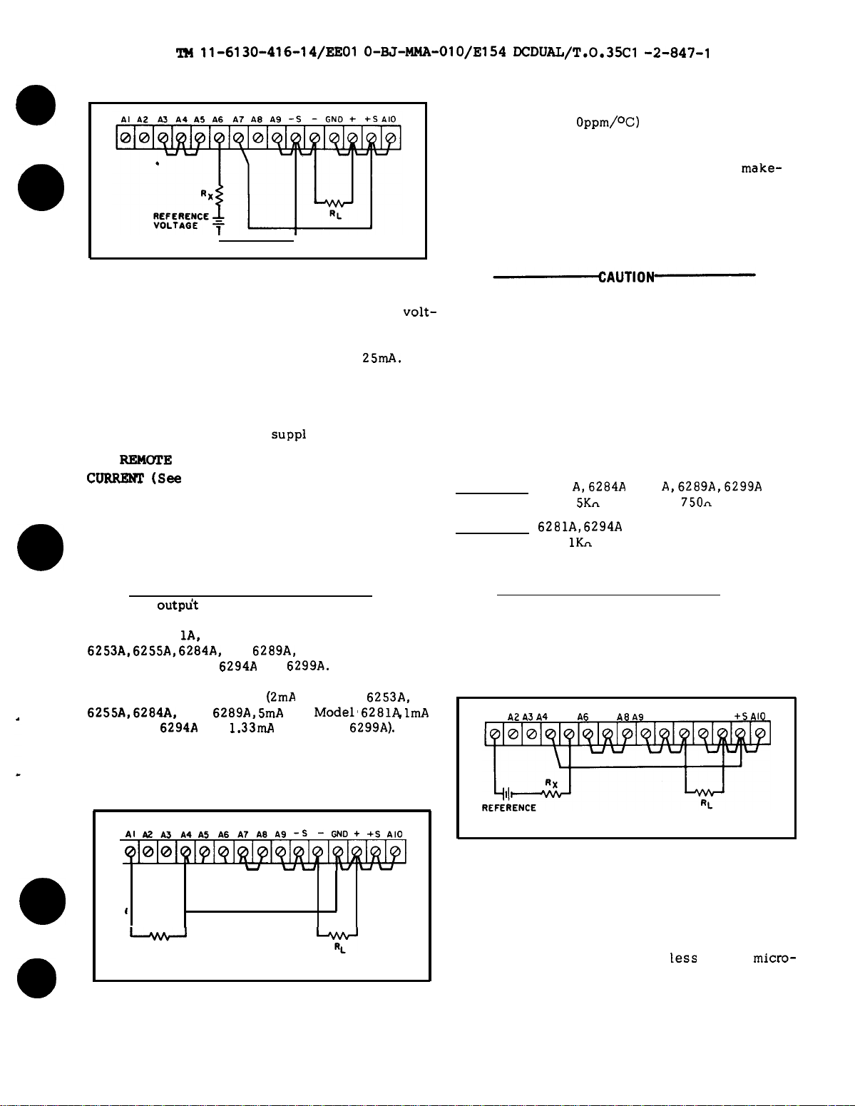
Oppm/oC) programming resistors
A
make-
Figure 3-4.
Remote Voltage Programming
(Constant Voltage)
voltage programming. In this mode, the output
volt-
age will vary in a 1 to 1 ratio with the programming
voltage (reference voltage) and the load on the programming voltage source will not exceed
25mA.
3-23 The impedance matching resistor (Rx) for the
programming voltage source should be approximately
500 ohms to maintain the temperature and stability
SUPP1
specifications of the power
REMOl’E
3-24
CURRENl! (Ses
PROGRAMMING, CONSTANT
Figure 3-1 for controls and
y.
indicators. )
3-25 Either a resistance or a voltage source can be
used to control the constant current output of the
supply. The CURRENT controls on the front panel
are disabled according to the following procedures.
3-26 Resistance Programming (Figure 3-5). In this
outpdt
mode, the
by the programming coefficient — 200 ohms per Amp
for Model 628
6253A, 6255A, 6284A,
Ampere for Models
ming coefficient is determined by the Constant Cur-
rent programming current
6255A, 6284A,
for Model
current is adjusted to within 10% at the factory. If
greater programming accuracy is required, it maybe
a thieved by changing resistor R 19 as outlined in
Section V.
current varies at a rate determined
1A,
500 ohms per Ampere for Models
and
6289A,
and 1000 ohms per
6294A
and
6299A.
The program-
(2mA
for Models
and
6294A
6289A, 5mA
and
1.33mA
for Model’
for Model
6253A,
6281A lmA
6299A).
This
If the programming terminals
should open at any time during this
mode, the output current will rise to a
value that may damage the power supply and/or the load. To avoid this
possibility, connect a resistor across
the programming terminals having the
value listed below. Like the programming resistor, this resistor should be
of the low noise, low temperature coefficient type.
Model
Resistance
Model
Resistance
3-28 Voltage Programming (Figure 3-6). In this
mode, the output current will vary linearly with
changes in the programming voltage. The programming voltage should not exceed 1.2 Volts. Voltage in
excess of 1.2 Volts will result in excessive power
dissipation in the instrument and possible damage.
Al A2 A3 A4 AS A6 A? A8 A9 -S – GNO + +S
6253
A,6284A 6255
1.
5Kn
6281A, 6294A
lKA
(Al and AS)
A,6289A,6299A
750n
AIO
AI A2A3A4A5A6A7A8A9
OlOlOIQ1~lQ1
u
-----
1
-----
PROGRAMMING
RESISTOR
Figure 3-5.
b
Remote Resistance Programming
(Constant Current)
VOLTAGE
-S-
GM++ SAIO
u
1%’lddq@..j&l
y
3-3
Figure 3-6.
3-29 The output current will be the programming
voltage divided by 1 ohm. The current required
from the voltage source will be
ampere. The impedance matching resistor (Rx)
should be approximately 500 ohms if the temperature
coefficient and stability specifications of the power
supply are to be maintained.
Remote Volta ge Programming
(Constant Current)
less
than 25
micro-
Page 22
TM 11-6130-416-14/EE010-BJ-MMA-010/E154 DCDUAL/T.O.35C1-2-847-1
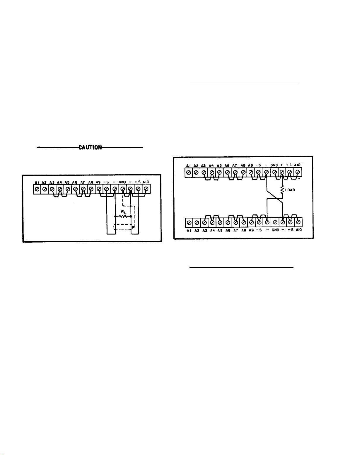
3-30 REMOTE SENSING (See Figure 3-7)
3-31 Remote sensing is used to maintain good regu-
lation at the load and reduce the degradation of regulation which would occur due to the voltage drop
in the leads between the power supply and the load.
Remote sensing is accomplished by utilizing the
strapping pattern shown in Figure 3-7. The pwer
supply should be turned off before changing strap-
ping patterns. The leads from the +S terminals to
the load will carry less than 10mA of current, and
it is not required that these leads be as heavy as
the load leads. However, they must be twisted or
shielded to minimize noise pick-up.
Observe polarity when connecting the
sensing leads to the load.
that it is possible to operate a power supply simultaneously in the remote sensing and Constant Voltage/Constant Current remote programming modes.
3-35 SERIES OPERATION
3-36 Normal Series Connections (Figure 3-8). Two
or more power supplies can be operated in series to
obtain a higher voltage than that available from a
single supply. When this connection is used, the
output voltage is the sum of the voltages of the individual supplies. Each of the individual supplies
must be adjusted in order to obtain the total output
voltage. The power supply contains a protective
diode connected internally across the output which
protects the supply if one power supply is turned off
while its series partner(s) is on.
Figure 3-7.
Remote Sensing
3-32 Note that it is desirable to minimize the drop
in the load leads and it is recommended that the
drop not exceed 1 Volt per lead if the power supply
is to meet its dc specifications. If a larger drop
must be tolerated, please consult a Hewlett-Packard
field representative.
NOTE
Due to the voltage drop in the load
leads, it may be necessary to readjust
the current limit in the remote sensing
mode.
3-33 The procedure just described will result in a
low dc output impedance at the load. If a low ac
impedance is required, it is recommended that the
following precautions be taken:
a. Disconnect output capacitor C20 by dis-
connecting the strap between A9 and -S.
b. Connect a capacitor having similar char-
acteristics (approximately same capacitance, same
voltage rating or greater, and having good high frequency characteristics) across the load using short
leads.
3-34 Although the strapping patterns shown in Figures 3-3 through 3-6 employ local sensing, note
Figure 3-8.
Normal Series Connections
3-37 Auto-Series Connections (Figure 3-9). The
Auto-Series configuration is used when it is desir-
able to have the output voltage of each of the series
connected supplies vary in accordance with the
setting of a control unit. The control unit is called
the master; the controlled units are called slaves.
At maximum output voltage, the voltage of the
slaves is determined by the setting of the front
panel VOLTAGE control on the master. The master
supply must be the most positive supply of the
series. The output CURRENT controls of all series
units are operative and the current limit i
S equal to
the lowest control setting. If any output CURRENT
controls are set too low, automatic crossover to
constant current operation will occur and the out-
put voltage will drop. Remote sensing and pro-
gramming can be used; however, the strapping ar-
rangements shown in the applicable figures show
local sensing and programming.
3-38 In order to maintain the temperature coefficient and stability specifications of the power supply,
the external resistors (Rx) shown in Figure 3-9
should be stable, low noise, low temperature coefficient (less than 30 ppm per degree Centigrade)
resistors. The value of each resistor is dependant
3-4
Page 23
TM 11-6130-416-14/EE010-BJ-MMA-010/E154 DCDUAL/T.O.35Cl-2-847-1
on the maximum voltage rating of the “master” sup-
ply. The value of Rx is this voltage divided by the
voltage programming current of the slave supply
(1/Kp where K
P is the voltage programming coef-
ficient). The voltage contribution of the slave is
determined by its voltage control setting.
controls of each power supply can be separately
set. The output voltage controls of one power supply should be set to the desired output voltage;
the other power supply should be set for a slightly
larger output volts ge.
The supply set to the lower
output voltage will act as a constant voltage
source; the supply set to the higher output will act
as a constant current source, dropping its output
Figure 3-10.
Normal Parallel Connections
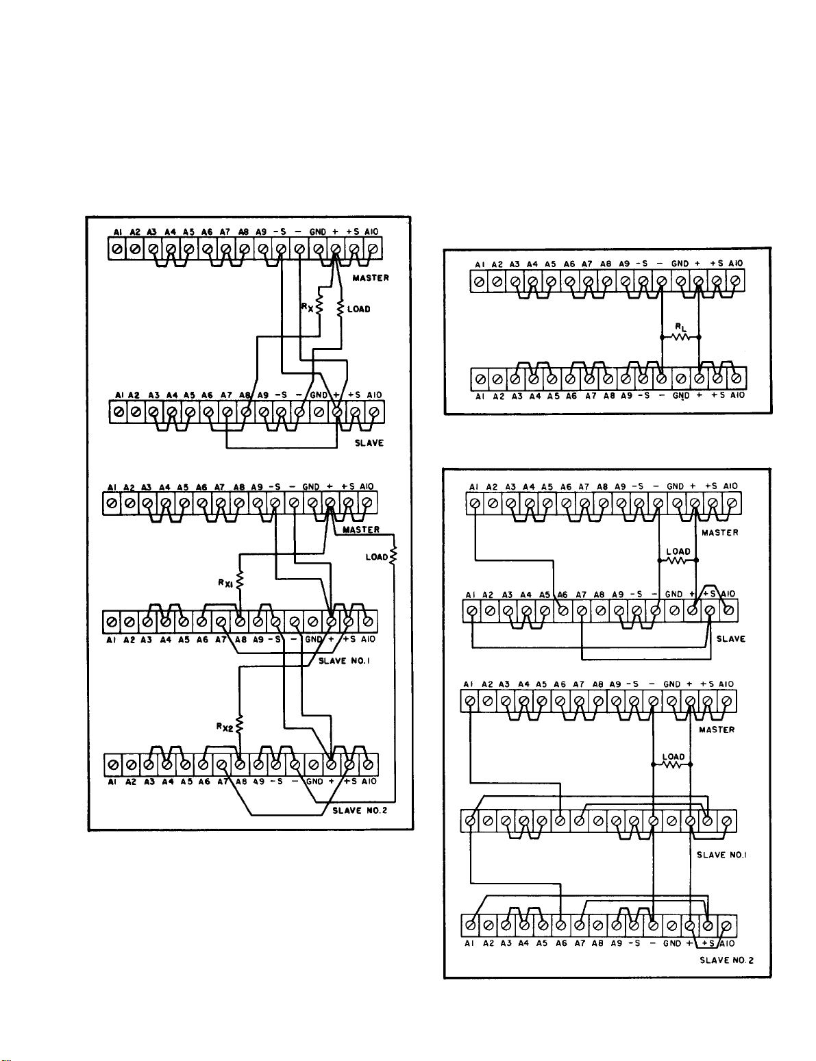
Figure 3-9.
Auto-Series, Two and Three Units
3-39 PARALLEL OPERATION (See Figure 3-1
for controls and indicators.)
3-40 Normal Parallel Connections (Figure 3-10).
Two or more power supplies can be connected in
parallel to obtain a total output current greater than
that available from one power supply. The total
output current is the sum of the output currents of
the individual power supplies. The output CURRENT
3-5
Figure 3-11.
Auto-Parallel, Two and Three Units
Page 24
TM 11-6130-416-14/EE010-BJ-MMA-010/E154 DCDUAL/T.O.35C1-2-847-1
voltage until it equals that of the other supply. The
constant voltage source will deliver only that frac-
tion of its total rated output current which is neces-
sary to fulfill the total current demand,
3-41
Auto-Parallel
shown in
permits equal current sharing under all load conditions, and allows complete control of output cur-
rent from one master power supply. The output current of each slave will be approximately equal to
the master’s regardless of the load conditions.
Because the output current controls of each slave
are operative, the y should be set to maximum to
avoid having the slave revert to constant current
operation; this would occur if the master output
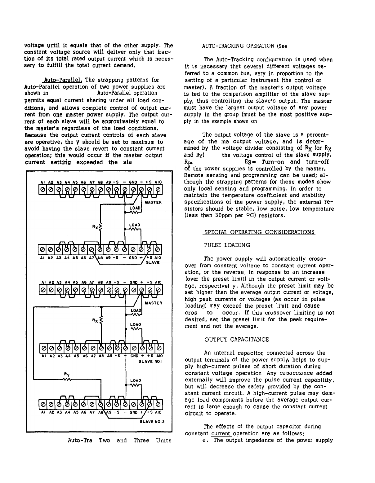
Auto-Parallel.
Figure 3-11.
current setting exceeded the slave’s.
The strapping patterns for
operation of two power supplies are
Auto-Parallel
operation
3-42
AUTO-TRACKING OPERATION (See
3-43
it is necessary that several different voltages referred to a common bus, vary in proportion to the
setting of a particular instrument (the control or
master). A fraction of the master’s output voltage
is fed to the comparison amplifier of the slave supply, thus controlling the slave’s output. The master
must have the largest output voltage of any power
supply in the group (must be the most positive supply in the example shown on
3-44
age of the master's
mined by the voltage divider consisting of Rx (or Rx
and Ry)
Rp.
of the power supplies is controlled by the master.
Remote sensing and programming can be used; although the strapping patterns for these modes show
only local sensing and programming. In order to
maintain the temperature coefficient and stability
specifications
sistors should be stable, low noise, low temperature
(less than 30ppm per °C) resistors.
The Auto-Tracking configuration
Figure 3-12).
The output voltage of the slave is a percent-
output voltage, and is deter-
and
where:
the voltage control of the slave supply,
ES=EMRp/Rx+Rp.
Turn-on and turn-off
of
the power supply, the external re-
Figure 3-12)
is
used when
3-45
3-46
3-47
over from constant voltage to constant current operation, or the reverse, in response to an increase
(over the preset limit) in the output current or volt-
age, respective y. Although the preset limit may be
set higher than the average output current or voltage,
high peak currents or voltages (as occur in pulse
loading) may exceed the preset limit and cause
crossever
desired, set the preset limit for the peak requirement and not the average.
3-48
3-49 An
output terminals of the power supply, helps to supply high-current pulses of short duration during
constant voltage operation. Any capacitance added
externally will improve the pulse current capability,
but will decrease the safety provided by the con-
stant current circuit. A high-current pulse may damage load components before the average output current is large enough to cause the constant current
circuit to operate.
SPECIAL OPERATING CONSIDERATIONS
PULSE LOADING
The power supply will automatically
to
occur.
OUTPUT CAPACITANCE
internal capacitor, connected acress the
If this crossover limiting is not
cross-
Figure 3-12.
Auto-Tracking,
Two and Three Units
3-50
constant current operation are as follows:
3-6
The effects of the output capacitor during
The output impedance of the power supply
a.
Page 25
TM 11-6130-416-14/EE010-BJ-MMA-010/E154 DCDUAL/T.O.35C1-2-847-1
decreases with increasing frequency.
b. The recovery time of the output voltage is
longer for load resistance changes.
c.A
large surge current causing a high power dissipation in the load occurs when the load resistance is reduced rapidly.
3-51
3-52
nals. Under norms 1 operating conditions, the diode
is reverse biased (anode connected to negative terminal). If a reverse voltage is applied to the output
terminals (positive voltage applied to negative terminal), the diode will conduct, shunting current
across the output terminals and limiting the voltage
to the forward voltage drop of the diode. This diode
protects the series transistors and the output electrolytic capacitor.
3-53
3-54
may actually deliver a reverse current to the power
supply during a portion of its operating cycle. An
external source cannot be allowed to pump current
into the supply without loss of regulation and pos-
sible damage to the output capacitor. To avoid
these effects, it is necessary to preload the sup-
ply with a dummy load resistor so that the power
supply delivers current through the entire operating
cycle of the load device.
REVERSE VOLTAGE LOADING
A diode is connected across the output termi-
REVERSE CURRENT LOADING
Active loads connected to the power supply
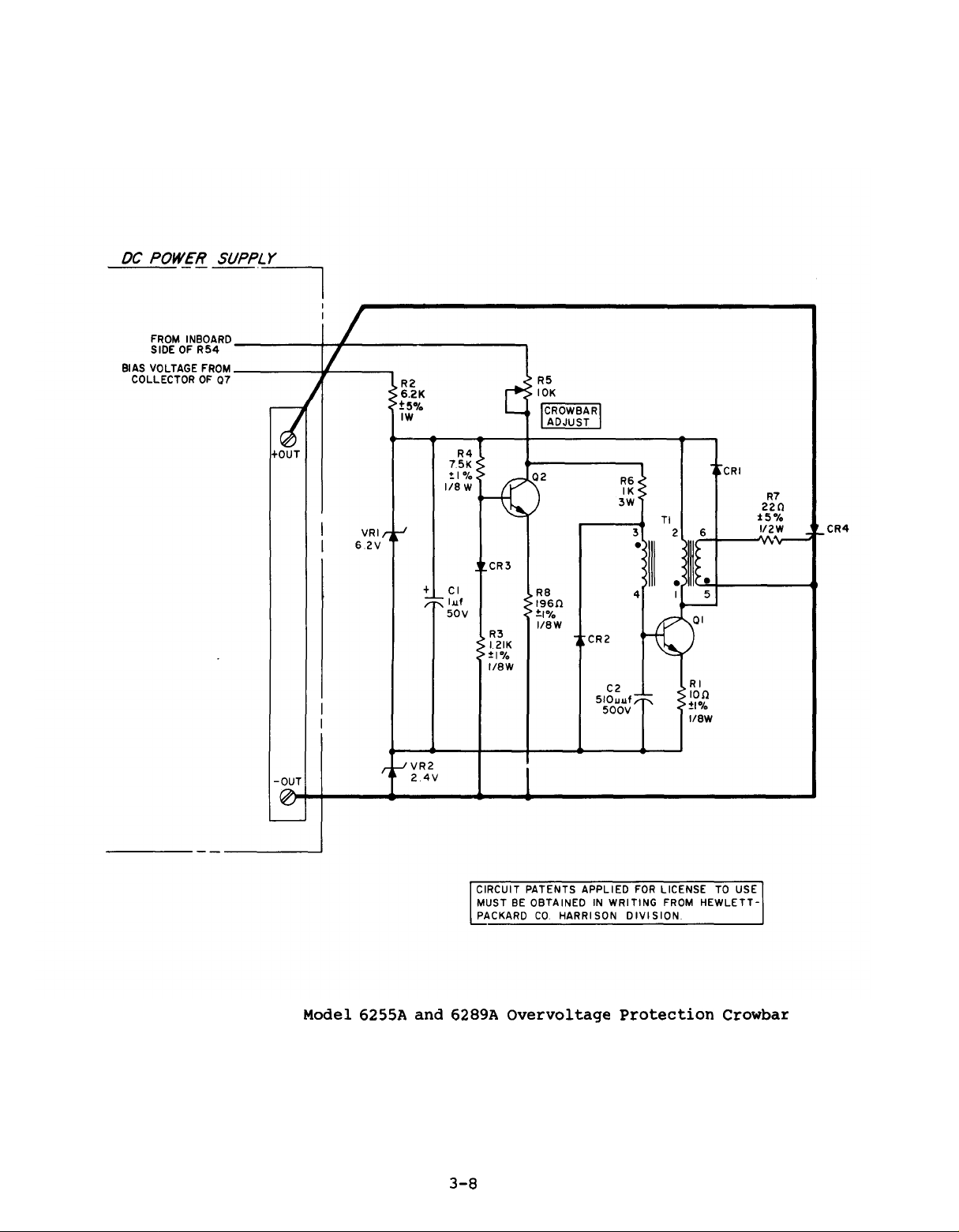
3-55
OVERVOLTAGE PROTECTION CROWBAR
(See
Figure 3-1
indicators and
schematic diagram.)
3-56
Use the following steps to adjust
the crowbar circuit.
a. Turn CROWBAR ADJUST fully
clockwise to set trip voltage to
maximum.
b.
control for desired crowbar trip
voltage.
tripping, trip voltage should exceed
desired output voltage by the following
amount:4% of
2V.
c.
ccw until crowbar trips, output goes to
OV or a small positive voltage.
d.
and output shorted until supply is
turned off.
supply off, then on.
e.
disabled, remove lead attached to
CROWBAR ADJUST potentiometer R5.
for controls and
Figure 3-13
Set power supply VOLTAGE
To prevent false crowbar
the output voltage plus
Slowly turn CROWBAR ADJUST
Crowbar will remain activated
To reset crowbar, turn
If CROWBAR must be completely
for the
3-7
Page 26
TM 11-6130-416-14/EE010-BJ-MMA-010/E154 DCDUAL/T.O.35C1-2-847-1
Figure 3-13.
Model 6255A and 6289A Overvoltage Protection Crowbar
3-8
Page 27
TM 11-6130-416-14/EE010-BJ-MMA-010/E154 DCDUAL/T.O.35C1-2-847-1
SECTION IV
PRINCIPLES OF OPERATION
Figure 4-1.
4-1
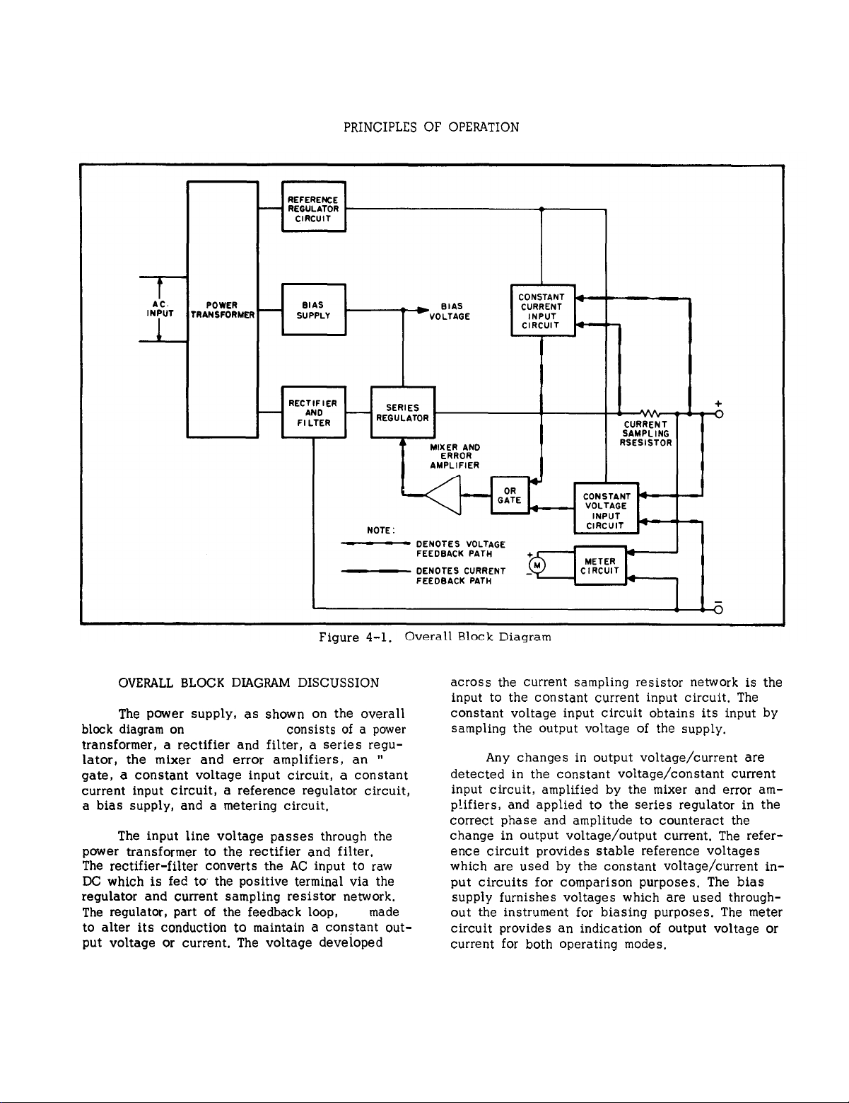
OVERALL BLOCK DIAGRAM DISCUSSION
4-2
The power supply, as shown on the overall
block diagram on
transformer,
Figure 4-1,
a
rectifier and filter, a series regu-
consists of a power
lator, the mixer and error amplifiers, an “OR”
gate, a constant voltage input circuit, a constant
current input circuit, a reference regulator circuit,
a bias supply, and a metering circuit.
4-3
The input line voltage passes through the
power transformer to the rectifier and filter.
The rectifier-filter
DC
which is fed to the positive terminal via the
converts the AC input to raw
regulator and current sampling resister network.
The regulator, part of the feedback loop,
is
made
to alter its conduction to maintain a constant output voltage or current. The voltage developed
across the current sampling resistor network is the
input to the constant current input circuit. The
constant voltage input circuit obtains its input by
sampling the output voltage of the supply.
4-4
Any changes in output voltage/current
detected in the constant voltage/constant
are
current
input circuit, amplified by the mixer and error amplifiers, and applied to the series regulator in the
correct phase and amplitude to counteract the
change in output voltage/output current. The reference circuit provides stable reference voltages
which are used by the constant voltage/current
in-
put circuits for comparison purposes. The bias
supply furnishes voltages which are used through-
out the instrument for biasing purposes. The meter
circuit provides an indication of output voltage or
current for both operating modes.
4-1
Page 28
TM 11-6130-416-14/EE010-BJ-MMA-010/E154 DCDUAL/T.O.35C1-2-847-1
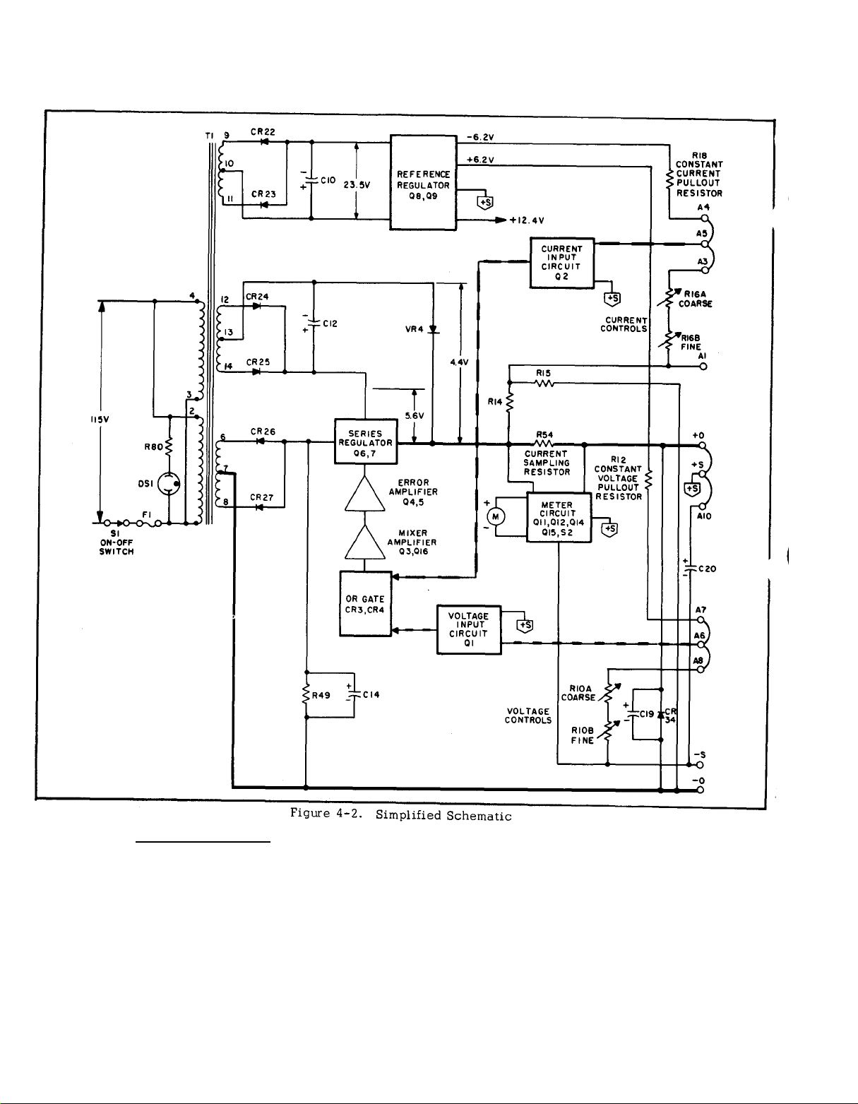
Figure 4-2.
4-5
SIMPLIFIED SCHEMATIC (See Figure
3-1 for controls and indicators.)
4-6 A simplified schematic of the power supply
is shown in Figure 4-2. It shows the operating
controls; the ON-off switch, the voltage and current programming controls R10 and R16. Figure
4-2 also shows the internal sources of bias and
reference voltages and their nominal magnitudes
with an input of 115 VAC.
4-7
Diode CR34, connected across the output
terminals of the power supply, is a protective de-
vice which prevents internal damage that might
occur if a reverse voltage were applied across the
output terminals.
connected across the output terminals when the
normal strapping pattern shown on Figure 4-2 is
employed.
Note that this capacitor can be removed
if an increase in the programming speed is desired.
Under these conditions,
insure loop stability.
4-2
Output capacitor, C20, is also
capacitor C19 serves to
Page 29

TM 11-6130-416-14/EE010-BJ-MMA-010/E154 DCDUAL/T.O.35C1-2-847-1
4-8 DETAILED CIRCUIT ANALYSIS [Refer
to overall schematic diagram (FO-1) at
rear of manual.]
4-9
controls and indicators.)
4-10 The feedback loop functions continuously to
keep the output voltage constant, during constant
voltage operation, and the output current constant,
during constant current operation. For purposes of
this discussion, assume that the unit is in con-
stant voltage operation and that the programming
resistors R10 A and B have been adjusted so that
the supply is yielding the desired output voltage.
Further assume that the output voltage instantaneously rises (goes positive) due to a variation in
the external load circuit.
4-11 Note that the change maybe in the form of a
slow rise in the output voltage or a positive going
AC signal.
point A6 through capacitor C1 and a DC voltage is
coupled to A6 through R10.
4-12 The rise in output voltage causes the voltage
at A6 and thus the base of Q1A to decrease (go
negative). Q1A now decreases its conduction and
its collector voltage rises. The positive going error voltage is amplified and inverted by Q3 and fed
to the bases of series transistors Q6 and Q7 via
emitter followers Q5 and Q4. The negative going
input causes Q6 and Q7 to decrease their conduction so that they drop more of the line voltage, and
reduce the output voltage to its original level.
FEEDBACK LOOP (See Figure 3-1 for
An AC signal is coupled to summing
dissipated in series transistor Q6. The bias voltage
for Q7 is developed across zener diode VR5, The
The conduction of Q7 will decrease as the collector-
to-emitter voltage of Q6 approaches the voltage
developed across the biasing diodes, At low output voltages Q7 is completely cutoff and all of the
load current flows through the shunt resistors. The
voltage that is dropped acress Q7 and the shunt
resistors reduces the voltage dropped across Q6,
thus diminishing its power dissipation. The reliability of the regulator is further increased by
mounting the shunt resistors outside the rear of
the cabinet so that the internal components are
operated under lower temperature conditions.
Diode CR11, connected across Q6, protects it from
reverse voltages that could develop across it dur-
ing parallel or auto-parallel operation if one supply is turned on before the other. Diodes CR18
and CR19 perform a similar function for Q7.
4-16 CONSTANT VOLTAGE INPUT CIRCUIT
(See Figure 3-1 for controls and in-
dicators.)
4-17 The circuit consists of programming resistor
R10A and B, and a differential amplifier stage (Q1
and associated components). Transistor Q1 con-
sists of two transistors housed in a single package.
The transistors have matched characteristics min-
imizing differential voltages due to mismatched
stages.
tials is minimized, since both transistors operate
at essentially the same temperature.
Moreover, drift due to thermal differen-
4-13 If the external load resistance is decreased
to a certain crossover point, the output current in-
creases until transistor Q2A begins to conduct.
During this time, the output voltage has also decreased to a level so that the base of Q1A is at a
high positive potential.
tion, its collector voltage decreases by the amount
necessary to back bias OR gate diode CR3 and the
supply is now in the constant current mode of operation.
current operation commences is determined by the
setting of CURRENT control R16. The operation of
the feedback loop during the constant current operating mode is similar to that occuring during
constant voltage operation except that the input to
the differential amplifier comparison circuit is obtained from the current sampling resistor network.
4-14 SERIES REGULATOR
4-15 The series regulator consists of transistor
stages Q6 and Q7 (see schematic at rear of manual).
Transistor Q6 is the series element, or pass transis-
tor, which controls the output. Transistor Q7, together with shunt resistors R81, R82, and R83, are
connected in a manner which minimizes the power
The crossover point at which constant
With Q1A in full conduc-
4-18 The constant voltage input circuit continuously compares a fixed reference voltage with a
portion of the output voltage and, if a difference
exists, produces an error voltage whose amplitude
and phase is proportional to the difference.
error output is fed back to the series regulator,
through an OR gate and the mixer/error amplifiers.
The error voltage changes the conduction of the
series regulator which, in turn, alters the output
voltage so that the difference between the two input voltages applied to the differential amplifier is
reduced to zero.
output voltage constant.
4-19 Stage Q1B of the differential amplifier is
connected to a common (+S) potential through impedance equalizing resistor R5. Resistors R6 and
R8 are used to zero bias the input stage, offsetting
minor base-to-emitter voltage differences in Q1.
The base of Q1A is connected to a summing point at
the junction of the programming resistor and the
current pullout resistor, R12. Instantaneous
changes in output voltage result in an increase or
decrease in the summing point potential. Q1A is
then made to conduct more or less, in accordance
with the summing point voltage change.
The above action maintains the
The
The re-
4-3
Page 30

TM 11-6130-416-14/EE010-BJ-MMA-010/E154 DCDUAL/T.O.35C1-2-847-1
sultant output error voltage is fed back to the
series regulator via OR-gate diode CR3 and the
remaining components of the feedback loop, Resistor R1, in series with the base of Q1A, limits
the current through the programming resistor during
rapid voltage turn-down.
form a limiting network which prevent excessive
voltage excursions from over driving stage Q1A.
Capacitors C1 and C2, shunting the programming
resistors, increase the high frequency gain of the
input amplifier.
resistor R12, serves as a trimming adjustment for
the programming current.
4-20
CONSTANT CURRENT INPUT CIRCUIT
(See
Figure 3-1
dicators.)
4-21
eration to the constant voltage input circuit. It
consists basically of the current programming resistors R16A and B, and a differential
stage (Q2 and associated components). Like
transistor Q1 in the voltage input circuit, Q2 consists of two transistors,
teristics,
4-22
cuit continuously compares a fixed reference voltage with the voltage drop
across the current sampling resistor
R54.
ferential amplifier produces an error
voltage which is proportional to this
difference.
in the feedback loop (amplifiers and
series regulator) function to maintain
4-23
tential through impedance equalizing resistor R26.
Resistors R25 and R28 are used to zero bias the input stage, offsetting minor base-to-emitter
differences in Q2.
put current on the positive line are felt at the current summing point and, hence, the base of Q2A.
Stage Q2A varies its conduction in accordance
with the polarity of the change at the summing
point. The change in Q2A’s conduction also varies
the conduction of Q2B due to the coupling effects
of the common emitter resister, R22. The error
voltage is taken from the collector of Q2B and fed
back to the series regulator through OR-gate diode
CR4 and the remaining components of the feedback
loop. The error voltage then varies the conduction
of the regulator so that the output current is main-
tained at the proper level.
This circuit is similar in appearance and op-
that are housed in a single package.
The constant current input cir-
If a difference exists, the dif-
the drop across the current sampling
resistors, and consequently the output
current, at a constant value.
Stage Q2B is connected to a common (+S) po-
Resistor R13, shunting pullout
for controls and in-
The remaining components
Instantaneous changes in out-
Diodes CR1 and CR2
amplifier
having matched charac-
voltage
4-24
Resistor R20, in conjunction with R21 and C3
helps stabilize the feedback loop, Diode CR5 limits voltage excursions on the base of Q2A. Resister R19, shunting the pullout resistor, serves as a
trimming adjustment for the programming current
flowing through R16.
4-25
4-26
stant voltage programming resisters are a shunt
load acress the output terminals of the power supply. If the output voltage changed, the current
through these resistors would tend to change re-
sulting in an output current change. The clamp
circuit is a return path for the voltage programming
current, the current that normally flows through the
programming resistors.
current into the constant voltage summing point
(A6) constant, thus eliminating the error due to
shunting effects of the constant voltage programming resistors.
4-27
back biases CR30 and Q1O during constant voltage
operation. When the power supply goes into con-
stant current operation, CR30 becomes forward
biased by the collector voltage of Q1A. This re-
sults in conduction of Q1O and the clamping of the
summing point at a potential only slightly more
negative than the normal constant voltage potential.
Clamping this voltage at approximately the same
potential that exists in constant voltage operation,
results in a constant voltage across, and consequently a constant current through the pullout re-
sistor (R12).
4-28
4-29
error signal from the constant voltage or constant
current input circuit to a level sufficient to drive
the series regulator transistors.
potential for mixer amplifier Q3 is established by
the emitter follower.
error voltage input from either the constant voltage
or constant current circuit via the OR-gate diode
(CR3 or CR4) that is conducting at that time.
Diode CR3 is forward biased, and CR4 reversed
biased, during constant voltage operation. The
reverse is true during constant current operation.
4-30
an equalizing network which provides for high frequency roll off in the loop gain response in order to
stabilize the feedback loop. Emitter follower transistors Q4 and Q5 are the error amplifiers serving
as the driver and predriver elements, respectively,
for the series regulator. Transistor Q4, together
VOLTAGE CLAMP CIRCUIT
During constant current operation the con-
The circuit maintains the
The voltage divider, R51, R52, and VR3,
MIXER AND ERROR AMPLIFIERS
The mixer and error amplifiers amplify the
The emitter bias
Transistor Q3 receives the
The RC network, composed of C5 and R30, is
4-4
Page 31

TM 11-6130-416-14/EE010-BJ-MMA-010/E154 DCDUAL/T.O.35C1-2-847-1
with diode CR17, provides a low resistance dis-
charge path for the output capacitance of the power
supply during rapid down programming.
4-31
4-32
supply similar to the main supply. It provides
stable reference voltages which are used throughout the unit.
rived from smoothed
wave rectifier (CR22 and CR23) and filter capacitor
C10. The +6.2 and -6.2 voltages, which are used
in the constant voltage and current input circuits
for comparison purposes, are developed across
temperature compensated Zener diodes VR1 and
VR2. Resister R43 limits the current through the
Zener diodes to establish an optimum bias level.
4-33
ulating transistor Q9 and error amplifier Q8. Output voltage changes are detected by Q8 whose base
is connected to the junction of a voltage divider
(R41, R42) connected directly across the supply. Any
error signals are amplified and inverted by Q8 and
applied to the base of series transistor Q9. The
series element then alters its conduction in the
direction and by the amount necessary to maintain
the voltage across VR1 and VR2 constant. Resistor
R46, the emitter resistor for Q8, is connected in a
manner which minimizes changes in the reference
voltage caused by variations in the input line.
Output capacitor C9 stabilizes the regulator loop.
4-34
controls and indicators.)
REFERENCE CIRCUIT
The reference circuit is a feedback power
The reference voltages are all de-
DC
obtained from the full
The regulating circuit consists of series reg-
METER CIRCUIT (See
Figure 3-1
for
this divider is connected across the sampling re-
sistor network. The amplified output of the differ-
ential amplifier is used to deflect the meter.
4-38
having a fixed gain of ten, Stage Q11B of the am-
plifier receives a negative voltage from the appli-
cable voltage divider when S2 is in one of the
voltage positions while stage Q11A is connected
to the +S (common) terminal. With S2 in a current
position, stage Q11A receives a positive voltage
from the applicable voltage divider while stage
Q11B is connected to the +S terminal. The differential output of the amplifier is taken from the
collectors of Q12 and Q14. Transistor Q15 is a
constant current source which sets up the proper
bias current for the amplifier. Potentiometer R63
permits zeroing of the meter.
current limiting feature which protects the meter
movement against overloads. For example, if
METER switch S2 is placed in the low current
range when the power supply is actually delivering a higher ampere
fiers are quickly driven into saturation limiting the
current through the meter to a safe value.
The differential
4-39
The meter amplifier contains an inherent
amplifier is a stable device
output,
the differential
ampli-
4-35
The meter circuit provides continuous indica-
tions of output voltage or current on a single multi-
ple range meter. The meter can be used either as a
voltmeter or an ammeter depending upon the position
of the METER switch S2 on the front panel of the
supply. This switch also selects one of two meter
ranges on each scale. The meter circuit consists
basically of a selection circuit (switch S2 and asso-
ciated voltage dividers), stable differential
stages (Q11, Q12, and Q14), and the meter movement.
4-36
age divider is connected to the differential
fier Input. When the METER section of S2 is in
one of the voltage positions,
divider R59, R60, and R61 (connected across the
output of the supply is the input to the differen-
tial amplifier.
4-37
the voltage acress divider R56, R57, and R58 is
the input to the differential
The selection circuit determines which volt-
the voltage across
When S2 is in one of the current positions
amplifier. Note that
amplifier
ampli-
4-5
Figure 4-3.
Figure 4-4.
Voltmeter Connections,
Simplified Schematic
Simplified Schematic
Ammeter Connections,
Page 32

TM 11-6130-416-14/EE010-BJ-MMA-010/E154 DCDUAL/T.O.35C1-2-847-1
4-40 Figures 4-3
tions when the METER section of S2 is in the
and
4-4
show the meter connec-
output voltage (drop acress R59 and R60) to the
meter
higher voltage and current range positions, respectively. For the sake of simplicity, some of the
actual circuit components are not shown on these
drawings,
With the METER switch in the higher
voltage range, position 2, the voltage drop acress
R59 is the input to the meter amplifier and the
meter indicates the output voltage acress the +S
and -S terminals.
be switched to the low voltage position (1)
For low output voltages, S2 can
result-
ing in the application of a larger percentage of the
4-41 As
switch in the high current position (3) the voltage
drop across R58 is applied to the meter amplifier
and the meter indicates the output current which
flows through the sampling resistor network. For
low values of output current, the METER switch
can be set to position 4 and the voltage drop across
R57 and R58 is applied to the meter amplifier.
amplifier.
illustrated
in
Figure 4-4 with the METER
4-6
Page 33

TM 11-6130-416-14/EE010-BJ-MMA-010/E154 DCDUAL/T.O.35C1-2-847-1
SECTION V
MAINTENANCE
5-1 INTRODUCTION
CAUTION
Do not directly short out
any of the large capacitors
as it places too much stress
on them.
tors through a load
resistor.
5-2
Upon receipt of the power supply, the performance check
This check is suitable for incoming inspection. If
a fault is detected in the power supply while making
the performance check or during normal operation,
proceed to the troubleshooting
graph 5-41).
graph 5-46),
and calibrations
the power supply to normal operation, repeat the
performance check to ensure that the fault has been
properly corrected and that no other faults exist.
Before doing any maintenance checks, turn on power supply, allow a half-hour warm-up, and read the
general information regarding measurement techniques
(Paragraph 5-3).
5-3 GENERAL MEASUREMENT TECHNIQUES
(Paragraph 5-10)
Discharge
After trouble shooting
perform any necessary adjustments
(Paragraph 5-48).
capaci-
should be made.
procedures
and repair
(Para-
Before returning
(Para-
shown
tics should never
if the load is connected across the rear terminals.
Note
terminals, the monitoring leads are connected at A,
not B, as shown in
the measuring
ment that includes the resistance of the leads be-
tween the output terminals and the point of connection.
5-6
sampling resistor should be a four-terminal
tor. The four terminals are connected as shown in
Figure 5-2. In
the low noise, low temperature coefficient (less
than 30ppm/°C) type and should be used at no
more than 5% of its rated power so that its temperature rise will be minimized.
in Figure 5-1.
be
measured
that when
Figure 5-1.
device at A
Figure 5-1.
For output current measurements, the current
Front Panel Terminal Connections
addition, the resister should be of
The performance
on the
measurements
front
are made at
Failure to connect
will result in
characteris-
terminals
the
front
a measure-
resis-
DO not touch heat sinks or
power transistors mounted
on heat sinks as they are
very hot after instrument
has been on and operating.
5-4
The measuring device must be connected
across the sensing leads of the supply or as close
to the output terminals as possible when measuring
the output impedance, transient response, regulation, or ripple of the power supply in order to
achieve valid measurements. A measurement made
across the load includes the impedance of the leads
to the load and such lead lengths can easily have
an impedance several orders of magnitude greater
than the supply impedance, thus invalidating the
measurement.
5-5
The monitoring device should be connected
to the +S and -S terminals (see
Figure 3-2) or
as
Figure 5-2.
5-7
When using an oscilloscope,
minal of the power supply and then ground the case
of the oscilloscope to this same point. Make certain that the case is not also grounded by some
other means (Power line). Connect both oscilloscope input leads to the power supply ground terminal and check that the oscilloscope is not exhibiting a ripple or transient due to ground loops, pickup, or other means.
5-1
Output Current Measurement
Technique
ground one ter-
Page 34

TM 11-6130-416-14/EE010-BJ-MMA-010/E154 DCDUAL/T.O.35C1-2-847-1
5-8
TEST EQUIPMENT REQUIRED
5-9 Table 5-1
perform the various procedures described in this
Section.
Care must be exercised when using an
electronic null detector in which one
input terminal is grounded to avoid
ground loops and circulating currents.
lists the test equipment required to
CAUTION
c.
Set METER switch to highest voltage
range and turn on supply.
d. Adjust VOLTAGE control(s) until front
panel meter indicates exactly the maximum rated
output voltage.
e.
Differential
maximum rated output voltage within ±2%.
5-15
5-4
range and turn on supply.
panel meter indicates exactly the maximum rated
output current.
0.02 Vdc.
Current.
a. Connect test setup as shown in Figure
leaving switch S1 open.
b. Turn CURRENT controls fully clockwise.
c.
Set METER switch to highest current
d. Adjust VOLTAGE control(s)
e. Differential
voltmeter should indicate
Proceed as follows:
until front
voltmeter should read 1.0
±
Figure 5-3.
5-10
5-11
ing inspection check and appropriate
test can be repeated either to check the operation of
the instrument after repairs or for periodic maintenance tests. The tests are performed using a 115Vac
rect result is not obtained for a particular check,
Figure 3-1
5-13
5-14
terminals of supply.
lows:
Model
Resistance 6
and -S terminals of supply observing correct polarity.
PERFORMANCE TEST
The following test can be used as an incom-
60Hz, single phase input power source. If the cordo not adjust any controls; proceed to trouble-
shooting
(Paragraph 5-41).
5-12
CONSTANT VOLTAGE (CV) TESTS (See
Rated Output and Meter Accuracy.
Voltage.
a. Connect load resistor across rear output
b. Connect differential
Differential
for controls and indicators.)
Proceed as follows:
6253A 6255A 6281A 6284A 6289A 6294A
26
Voltmeter Substitute,
Test Setup
portions of the
Resistor value to be as fol-
6
1.5
voltmeter across +S
26
60
Figure 5-4.
5-16.
load regulation, proceed as follows:
range and turn on supply.
panel meter indicates exactly the maximum rated
output voltage.
ferential voltmeter.
not vary from reading recorded in step
than the following:
Load Regulation.
a. Connect test setup as shown in
b. Turn CURRENT controls fully clockwise.
c.
Set METER switch to highest current
d. Adjust VOLTAGE control(s) until front
e.
Read and record voltage indicated on dif-
f.
Disconnect load resistors.
Reading on differential
g.
Output Current Test Setup
To check constant voltage
Figure 5-5.
voltmeter should
e by
more
5-2
Page 35

TM 11-6130-416-14/EE010-BJ-MMA-010/E154 DCDUAL/T.O.35C1-2-847-1
TYPE
Differential
Voltmeter
Variable
Voltage
Transformer
AC Voltmeter
Oscilloscope
Oscillator
DC Voltmeter
Repetitive
Load Switch
Resistive
Loads
Table 5-1.
REQUIRED
CHARACTERISTICS
Sensitivity: 1mV full scale (min.).
Input impedance: 10 megohms (min.).
Range: 90-130 volts.
voltmeter accurate within 1 volt.
Accuracy: 2%. Sensitivity: 1mV full
scale deflection (min.).
Sensitivity: 10OµV/cm. Differential
input.
Range: 5 Hz to 600 kHz. Accuracy:
2%. Output: 1OV rms.
Accuracy: 1%.
20, 000 ohms/volt (min.).
Rate: 60-400 Hz, 2µsec rise and
fall
time.
Values: See
Figure 5-4.
Input resistance:
Paragraph 5-14
±5%, 75 watts.
Equipped with
Test Equipment Required
and
USE
Measure
calibration procedures
Vary AC input
Measure AC voltages and
ripple
Display transient response 140A plus 1400A
waveforms
Impedance checks
Measure
Measure transient
response
Power supply load resistors
DC
voltages;
DC
voltages
RECOMMENDED
MODEL
3420 (See Note)
---
403B
plug-in. 1402A
plug-in for spike
measurements
only,
200 CD
412A
See Figure 5-8,
---
Current
Sampling
Resistor
Resistor
Resistor
Resistor
Resistor
Capacitor
Decade
Resistance
Box
A satisfactory
source and null detector as shown in
justed so that the voltage difference between the supply being measured and the refer-
ence voltage will have the required resolution for the measurement being made. The
voltage difference will be a function of the null detector that is used. Examples of satisfactory null detectors are: 419A null detector, a dc coupled oscilloscope utilizing
differential
a 2mV change in voltage will result in a meter deflection of four divisions.
6253A, 6284A: O.33
6255A, 6289A: O.66
6281A:
6294A:
1
±1%, 2 watt non-inductive.
100
ohms,
Value: See
1/2 watt.
Value: See
1/2 watt.
500µf, 50
Range: 0-500K. Accuracy: 0.1%
plus 1 ohm.
contacts.
substitute for a differential
input, or a 50mV meter movement with a 100 division scale. For the latter,
0.2
1
±5%, 10 watt.
Paragraph 5-59.
Paragraph 5-62.
wVdc.
Make-before-break
±0.1%,
±0.1%
Figure 5-3.
NOTE
voltmeter is to arrange a reference voltage
Measure current; cal-
ibrate meter; constant current
ripple and noise
Measure impedance
Measure impedance
Calibrate programming
current
Calibrate programming
current
Measure impedance
Measure programming
coefficients
The reference voltage source is ad-
(CC)
See Parts List
R54
---
---
---
---
---
---
5-3
Page 36

TM 11-6130-416-14/EE010-BJ-MMA-010/E154 DCDUAL/T.O.35C1-2-847-1
Model No.
Variation (mVdc)
Model No.
Variation (mVdc)
5-17 Line Regulation: To check the line regulation,
proceed as follows:
a. Connect variable auto transformer between
input power source and power supply power input.
b. Turn CURRENT controls fully clockwise.
c. Connect test setup shown in Figure 5-5.
d. Adjust variable auto transformer for 105Vac
input.
e.
Set METER switch to highest voltage
range and turn on supply.
f. Adjust VOLTAGE control(s) until front
panel meter indicates exactly the maximum rated
output voltage.
Read and record voltage indicated on dif-
g.
ferential voltmeter.
h. Adjust variable auto transformer for 125Vac
input.
i.
Reading on differential voltmeter should
not vary from reading recorded in step g by more
than the following:
Model No.
Variation (mVdc)
Model No. 6281A 6294A
Variation (mVdc)
6253A, 6284A 6255A, 6269A
±6
6281A
±5
6253A, 6284A 6255A, 6289A
±4
±2.75
±6
6294A
±8
±6
±8
5-19 The amount of ripple and noise that is present
on the power supply output is measured either in
terms of the RMS or (preferably) peak-to-peak value.
The peak-to-peak measurement is particularly im-
portant for applications where noise spikes could
be detrimental to a sensitive load, such as logic
circuitry. The RMS measurement is not an ideal
representation of the noise, since fairly high out-
put noise spikes of short duration could be present
in the ripple and not appreciably increase the RMS
value.
5-20 The technique used to measure high frequency
noise or "spikes" on the output of a power supply
is more critical than the low frequency ripple and
noise measurement technique; therefore the former
is discussed separately in Paragraph 5-28.
Figure 5-5.
5-18 Ripple and Noise. Ripple and noise measurement can be made at any input AC line voltage
combined with any DC output voltage and load current
within rating.
Load Regulation, Constant Voltage
Test Setup
Figure 5-6. CV (Constant Voltage)
Ripple and Noise Test Setup
5-4
Page 37

TM 11-6130-416-14/EE010-BJ-MMA-010/E154 DCDUAL/T.O.35C1-2-847-1
5-21
Ripple and Noise Measurements.
shows an incorrect method of measuring p-p ripple.
Note that a continuous ground loop exists from the
third wire of the input power cord of the supply to
the third wire of the input power cord of the oscil-
loscope via the grounded power supply case, the
wire between the negative output terminal of the
power supply and the vertical input of the scope,
and the grounded scope case. Any ground current
circulating in this loop as a result
in potential EG between the two ground points
causes an IR drop which is in series with the scope
input. This IR drop, normally having a 60Hz line
frequency fundamental, plus any pickup on the un-
shielded leads interconnecting
scope, appears on the face of the CRT. The magnitude of this resulting noise signal can easily be
much greater than the true ripple developed between
the plus and minus output terminals of the power
supply, and can completely invalidate the measure-
ment.
5-22
The same ground current and pickup problems
can exist if an RMS voltmeter is substituted in
place of the oscilloscope
the oscilloscope display, unlike the true RMS
meter reading, tells the observer immediately
whether the fundamental period of the signal dis -
played is 8.3 milliseconds (1/120 Hz) or 16.7
milliseconds (1/60 Hz). Since the fundamental ripple frequency present on the output of
is 120
Hz
(due to full-wave rectification),
cilloscope display showing a 120 Hz fundamental
component is indicative of a “clean” measurement
setup, while the presence of a 60 Hz fundamental
usually means that an improved setup will result
in a more accurate (and lower) value of measured
ripple.
in Figure 5-6.
Figure 5-6A
of
the difference
the power supply and
However,
an
supply
an
os-
will flow through this shield, thus inducing a
noise signal in the shielded leads.
5-25 To
playing ripple that is induced in the leads or picked
up from the grounds, the (+) scope lead should be
shorted to the (-) scope lead at the power supply
terminals. The ripple value obtained when the
leads are shorted should be subtracted from the
actual ripple measurement.
5-26 In
method of
nate non-real components of ripple and noise so
that a satisfactory measurement may be obtained.
However, in more stubborn cases it may be necessary to use a differential
put as shown in
single conductor shielded cables may be substituted in place of the shielded two-wire cable with
equal success.
jection, a differential
the difference in signal between its two vertical
input terminals, thus ignoring the effects of any
common mode signal introduced because of the
difference in the AC potential between the power
supply case and scope case.
ferential input scope in this manner, however, it
is imperative that the common mode rejection capability of the scope be verified by shorting together its two input leads at the power supply and
observing the trace on the CRT. If this trace is a
straight line, the scope is properly ignoring any
common mode signal present. If this trace is not
a straight line, then the scope is not rejecting the
ground signal and must be realigned in accordance
with the manufacturer’s
common mode rejection is attained.
verify that the oscilloscope is not dis-
most cases, the single-ended scope
Figure 5-6B
Figure 5-6C. If
Because of its common mode re-
will be adequate to elimi-
scope with floating in-
desired, two
oscilloscope displays only
Before using a dif-
instructions until proper
5-23 Figure 5-6B
suring the output ripple of a constant voltage pow-
er supply using a single-ended scope. The ground
loop path is broken by floating the supply output.
Note that to ensure that no potential difference
exists between the supply and the oscilloscope, it
is recommended that whenever possible they both
be plugged into the same AC power buss. If the
same buss cannot be used, both AC grounds must
be at earth ground potential.
5-24
ed two-wire cable should be used to connect the
output terminals of the power supply to the vertical
input terminals of the scope. When using a twisted pair, care must be taken that one of the two
wires is connected to the grounded input terminal
of the oscilloscope.
wire, it is essential for the shield to be connected
to ground at one end only so that no ground current
Either a twisted pair or (preferably)
shows a correct method of mea-
a
shield-
When using shielded two-
5-5
5-27 To
ceed as follows:
meter as shown in
and adjust VOLTAGE control until front panel meter
indicates maximum rated output voltage.
less than 200µV RMS and 1mV p-p.
5-28
quency spike measurement is being made, an in-
strument of sufficient bandwidth must be used; an
oscilloscope with a bandwidth of 20 MHz or more is
adequate. Measuring noise with an instrument that
has insufficient
quency spikes detrimental to the load.
5-29
check the ripple and noise output, proConnect the oscilloscope or RMS volt-
a.
Figures 5-6B or 5-6C.
b. Turn the CURRENT control fully clockwise
c.
The observed ripple and noise should be
Noise Spike Measurement. When a high fre-
bandwidth may conceal high fre-
The test setups illustrated
in Figures 5-6A
Page 38

TM 11-6130-416-14/EE010-BJ-MMA-010/E154 DCDUAL/T.O.35C1-2-847-1
and
5-6B
are generally
ing spikes; a differential oscilloscope is necessary.
Furthermore,
5-6C
must be modified if accurate spike measure-
ment is to be achieved:
1. As shown in
must be substituted
2. Impedance matching resistors must be
included to eliminate standing waves and cable
ringing, and the capacitors must be connected to
block the
DC
not
the measurement concept of
Figure 5-7,
for the shielded two-wire cable.
current path.
acceptable for
two coax cables,
measur-
Figure
range and turn on supply.
panel meter indicates exactly the maximum rated
output voltage.
switch setup.
display is obtained on oscilloscope. Waveform
should be within the tolerances shown in
5-9
value in less than 50 microseconds).
a. Connect test setup shown in
b. Turn CURRENT controls fully clockwise.
c.
Set METER switch to highest current
d. Adjust VOLTAGE control(s) until front
e. Close line switch on repetitive load
f. Adjust 25K potentiometer until a stable
(output should return to
within
Figure 5-8.
Figure
15mV of original
Figure 5-7.CV
3. The length of the test leads outside the
coax is critical and must be kept as short as possible; the blocking capacitor and the impedance
matching resister should be connected directly from
the inner conductor of the cable to the power supply
terminals.
4. Notice that the shields of the power supply end of the two coax cables are not connected to
the power supply ground, since such a connection
would give rise to a ground current path through the
coax shield, resulting in an erroneous measurement.
5. The measured noise spike values must be
doubled, since the impedance matching resisters,
constitute
scope should be less than O.5mV
5-30
the normal measurement of low frequency ripple and
noise; simply remove the four terminating resisters
and the blocking capacitors and substitute a higher
gain vertical plug-in in place of the wide-band plug-
in required for spike measurements. Notice that
with these changes,
cable version of
a
2-to-1 attenuator.
6. The noise spikes observed on the oscillo-
The circuit of
Figure 5-6C.
Noise Spike Test Setup
p-p.
Figure 5-7
Figure 5-7
can also be used for
becomes a two-
Figure 5-8.
Transient Response, Test Setup
5-31
transient recovery time proceed as follows:
Transient Recovery Time. To check the
5-6
Figure 5-9.
Transient Response, Waveforms
Page 39

TM 11-6130-416-14/EE010-BJ-MMA-010/E154 DCDUAL/T.O.35C1-2-847-1
5-32
made by monitoring the output voltage with an oscilloscope while rapidly changing the remote programming resistance.
mote resistance is varied from zero ohms to the value that will produce maximum output voltage; and
for down-programming,
ied from the value that will produce maximum output
voltage to zero ohms. To check the up-programming
speed, make the connections indicated in
5-10;
Proqramming Speed. This measurement is
For up-programming, the re-
the remote resistance is var-
Figure
for down-programming,
simply remove RL.
will produce maximum output voltage of the supply.
This value is obtained by multiplying the program-
ming coefficient (200 ohms/volt, 300 ohms/volt
for Model 6294A) by the maximum rated output
voltage of the supply.
3. A mercury-wetted relay is employed to
rapidly switch the programming resistance from zero
to maximum at a 60 Hz rate. Other automatic
switching devices can be used; however, a handoperated switch connected acress the programming
resistor is not adequate, because the resulting one-
shot displays are difficult to observe on most oscilloscopes.
4. The time (T) required for the output volt-
age to change from zero volts to maximum rated out-
put or from maximum rated output to zero should be
less than 10 milliseconds.
5-33
pedance, proceed as follows:
Output Impedance. To check the output im-
a.
Connect test setup as shown in
Figure 5-11.
Figure 5-10.
The load resistance is included for up-programming
and removed for down-programming to present the
worst possible conditions for the supply to reach
the programmed voltage. Refer to Application Note
90, Power Supply Handbook for” further details on
remote programming speed. To check the programming speed, proceed as follows:
1. Restrap the rear barrier strip as indicated
in
Figure 5-10.
and A10 is removed.
capacitor C20 to increase the programming speed.
A minimum amount of output capacitance (C19) is
permanently wired to the output and should not be
removed, because the supply could oscillate under
certain load conditions. The programming speed increases by a factor of from 10 to 100 when the out-
put capacitor C20 is removed.
2. Connect the relay, oscilloscope, and programming resistor Rp as illustrated
Select the value of the programming resister that
CV Programming Speed, Test
Setup
Note that the jumper between +S
This disconnects the output
in Figure 5-10.
5-7
Figure 5-11.
b.
Set METER switch to highest voltage range
and turn CURRENT controls fully clockwise, and turn
on supply.
Adjust VOLTAGE control(s) until front
c.
panel meter reads 20 volts.
d. Set AMPLITUDE control on Oscillator to
10 volts (Ein) , and FREQUENCY control to 1 kHz.
e,
Record voltage across output terminals of
the power supply (Eo) as indicated on AC voltmeter.
f.
Calculate the output impedance by the
following formula: Zout = (EoR)/(Ein Eo=
rms voltage across power supply output
terminals.
= 1000.
R
Ein = 10 volts.
Output Impedance, Test Setup
Eo)
Page 40

TM 11-6130-416-14/EE010-BJ-MMA-010/E154 DCDUAL/T.O.35C1-2-847-1
The output impedance (Zout) should be
9.
less than 0.01 ohm.
h. Using formula of step f, calculate output
impedance at frequencies of 10kHz, 100kHz, and
lMHz. Values should be less than O. 05 ohm,
O. 5 ohm, and 5 ohms, respectively.
5-34
Figure 3-1 for controls and indicators.)
5-35
rent load regulation, proceed as follows:
and turn on supply.
Variation (mVdc)
Variation (mVdc)
CONSTANT CURRENT (CC ) TESTS (See
Load Regulation.
a. Connect test setup as shown in
b. Turn VOLTAGE control(s) fully clockwise.
c.
Set METER switch to highest current range
d. Adjust CURRENT control until front panel
meter reads exactly the maximum rated output current.
e.
Read and record voltage indicated on
differential
switch S1.
not vary from reading recorded in step e by more
than the following:
Model No.
Model No.
5-36
proceed as follows:
leaving switch S 1 open throughout test.
tween input power source and power supply power
input.
and turn on supply.
meter reads exactly the maximum rated output cur-
rent,
ferential voltmeter.
Vac input.
not vary from reading recorded in step g by more
than the follow ing:
Model No.
Variation (mVdc)
Model No.
Variation (mVdc)
5-37
pertaining to the ground
voltmeter.
f, Short out load resistor (Ry) by closing
Reading on differential
9. $
Line Recmlation.
a. Utilize test setup shown in
b. Connect variable auto transformer be-
C. Adjust auto transformer for 105Vac input.
d. Turn VOLTAGE control(s) fully clockwise.
e.
Set METER switch to highest current range
f. Adjust CURRENT controls until front panel
g, Read and record voltage indicated on difh, Adjust variable auto transformer for 125
i,
Reading on differential
Ritmle and Noise.
To check the constant cur-
Figure 5-4.
voltmeter should
6253A, 6284A
*O. 183
6281A
*o. 5
To check the line regulation
6253A, 6284A
+0. 183
6281A 6294A
+0. 15
Most of the instructions
loop and pickup problems
6255A, 6289A
+~265
6294A
*o. 35
Figure 5-4
voltmeter should
6255A, 6289A
*O. 265
+0. 35
CC
Figure 5-12.
associated with constant voltage ripple and noise
measurement also apply to the measurement of con-
stant current ripple and noise.
trates the most important precautions to be observed
when measuring the ripple and noise of a constant
current supply. The presence of a 120 cycle waveform on the oscilloscope is normally indicative of a
correct measurement method.
60 Hz as its fundamental component is typically associated with an incorrect measurement setup.
Ripple and Noise Test Setup
Figure 5-12
A wave shape having
illus-
5-8
Page 41

TM 11-6130-416-14/EE010-BJ-MMA-010/E154 DCDUAL/T.O.35C1-2-847-1
5-38
ripple and noise, proceed as follows:
meter as shown in
and turn on supply.
meter reads exactly the maximum rated output current.
less than the following:
Model 6253A,6284A 6255A,6289A 6281A 6294A
ITA rms
Ripple and Noise Measurement. To check the
a.
Connect the oscilloscope or RMS volt-
Figures 5-12B or 5-12C.
b. Rotate the VOLTAGE control fully CW.
c.
Set METER switch to highest current range
d. Adjust CURRENT control until front panel
e. The ripple and noise indication should be
2
5-39
5-40
supplies are conservatively operated to provide
maximum reliability
a supply may fail. Usually the instrument must be
immediately repaired with a minimum of “ down time”
and a systematic approach as outlined in succeeding
paragraphs can
repair.
5-41
5-42
this instrument, ensure that the fault is with the
instrument and not with an associated circuit. The
performance
determined without having to remove the instrument
from the cabinet.
5-43
at fault, check for obvious troubles such as open
fuse, a defective power cable, or an input power
failure.
open connections, charred components, etc.
trouble source cannot be detected by visual inspec-
has been located (by means of visual inspection or
TROUBLESHOOTING
Components within Hewlett-Packard power
y. In
greatly simplify and speed up the
TROUBLE
General.
Once it is determined that the power supply is
(each held by four retaining screws) and inspect for
tion, follow the detailed procedure outlined in suc ceeding paragraphs. Once the defective component
ANALYSIS
Before attempting to troubleshoot
test
(Paragraph 5-10)
Next, remove the top and bottom covers
0.5
spite of this, parts within
4
0.5
enables this to be
If the
Table 5-2.
Common Troubles
trouble anal ys is) correct it and re-conduct the performance test. If a component is replaced, refer to
the repair and replacement and adjustment and calibration paragraphs in this section.
5-44 A
eration is a helpful aid in troubleshooting,
is recommended that the reader review Section IV of
the manual before attempting to troubleshoot the
unit in detail. Once the principles of operation are
understood, logical application of this knowledge
used in conjunction with the normal voltage read-
ings shown on the schematic and the additional
procedures given in the following paragraphs should
suffice to isolate a fault to a component or small
group of components.
on the schematic are positioned adjacent to the
applicable test points (identified
bers on the schematic and printed wiring boards).
5-45 Table 5-2
able causes of many possible troubles.If
high or low output voltage is a symptom, there are
two methods of isolating the fault. The first is a
simplified procedure that involves only measuring
voltages; the second is a more thorough approach
requiring that transistor stages be opened or shor-
ted.
voltages as given in
Then the voltage levels at critical points (base and
collector) in the feedback loop should be measured
and compared to the normal voltages given on the
overall schematic diagram at the rear of the manual.
This method of troubleshooting
not aiways conclusive; a better method is described
in (2).
filtered dc voltages as given in
drive each stage in the feedback loop into conduc tion or cutoff by either shorting or opening the pre -
vious stage as indicated in
good understanding
includes the symptoms and prob-
Both methods are described as follows:
First, the reference, bias, and filtered dc
1.
Table 5-3
2. First, measure the reference, bias, and
of
the principles of op-
and it
The normal voltages shown
by
encircled num-
either
should be checked.
a
feedback loop is
Table 5-3.
Tables 5-4 or 5-5.
Then,
Symptom
Low output or no output voltage
High output voltage
High ripple
Probable Cause
Refer to
Refer to
a.
b. If output floating, connect lpf capacitor between output
c.
d. Ensure that supply is not in constant-current
e.
Table 5-3,
Table 5-3,
Check operating setup for ground-refer
and ground.
Check for excessive internal ripple; refer to
under loaded conditions.To
CURRENT control fully clockwise. *
Check for low voltage across C14, C12, or C1O.
5-9
then
5-4.
then
5-5.
to Paragraph 5-18.
Table 5-3.
operation
prevent this condition turn
Page 42

TM 11-6130-416-14/EE010-BJ-MMA-010/E154 DCDUAL/T.O.35C1-2-847-1
Symptom
Poor line regulation
Poor load regulation
(Constant Voltage)
Poor load regulation
(Constant Current)
Table 5-2.
Common Troubles (Continued)
Probable Cause
a.
Improper measuring technique; refer to
b. Check reference circuit voltages,
c.
Check reference circuit adjustment,
a.
Improper measuring technique; refer to
b. Check the regulation characteristics
follows:
(1) Connect differential
(2) Connect appropriate
across (+) and (-) output terminals
(3) Perform steps b through f of
(4) If the differential
0.5mV, replace VRl.
c.
Ensure that supply is not in constant-current
loaded conditions. To prevent this condition turn CURRENT
control fully clockwise. *
a.
Improper measuring technique; refer to
b. Check the regulation characteristics
follows :
(1) Connect differential
(2) Connect appropriate
across (+) and (-) output terminals
(3) Perform steps b through f of
(4) If the differential
O .5mV, replace VR2.
c.
C19, C20, and CR34 leaky.
d. Check clamp circuit, Q1O, CR30, VR3, and CR32.
e.
Ensure that supply is not crossing over into constant voltage
operation. To prevent this condition, load the supply and
turn the VOLTAGE control fully clockwise. *
voltmeter acress VR1
load resistor (Ry), given in
voltmeter reading varies by more than
voltmeter across VR2
load resistor (Ry), given in
voltmeter reading varies by more than
Paragraph 5-3.
Table 5-3.
Paragraph 5-62.
Paragraph 5-3.
of
Paragraph 5-16
Paragraph 5-3.
of
Paragraph 5-35
Zener diode VRl as
Figure 5-4,
operation under
Zener diode VR2 as
Figure 5-4,
Oscillates
Poor stability (Constant Voltage)
Poor stability (Constant Current)
Poor transient recovery
* See
Figure 3-1
for controls and indicators.
Check C5 open. Adjustment of R30; refer to
a.
b. Check R21 and C3 in current input circuit.
a.
Check +6 .2Vdc reference voltage
b. Noisy programming resistor R1O.
c.
CR1, CR2 leaky.
d. Check Rl, R12, R13, and C2 for noise or drift.
e.
Stage Q 1 defective.
a.
Check -6 ,2Vdc reference voltage
b. Noisy programming resistor R16.
c.
CR5, CR34, C19, C3 leaky.
d. Check R18, R19, R20, R21, and R54 for noise or drift.
e.
Stage Q2 defective.
a.
Check R30 and C5, Refer to adjustment procedure
Paragraph 5-64.
5-10
(Table 5-3).
(Table 5-3).
Paragraph 5-64.
Page 43

TM 11-6130-416-14/EE0110-BJ-MMA-010/E154° DCDUAL/T.0.35C1-2-847-1
Meter
Common
31
+s
+s
34
41
41
- out
Table 5-3.
Meter
Positive
+s
33
37
37
23
38
27
Reference, Bias, and filtered DC Troubleshooting
Normal Normal
Vdc
6.2
6.2
12.4
24
4.4
28V(6253A)
53V(6255A)
12V(6281A)
28V(6284A)
53V(6289A)
80V(6294A)
38V(6253A)
62V(62S5A)
21 V(6281A)
38V(6284A)
62V(6289A)
90V(6294A)
Ripple (P-P)
0. 5mV
0. 5mV
1. 4V.
o. 4V
O. 6V
o. 2V
o. 4V
o. 5V
O. 8V
5 mV
20mV
3V
lV
2V
3V
lV
lV
Probable
VR2
VR1
Q8, Q9
C1O, CR22,
CR23, T1
VR4
C12, CR24,
CR25, T1
C14, C16,
CR26, CR27,
R49, T1
Cause
Step
1
2
3
4
5
Table 5-4.
Action
Turn the VOLTAGE control fully
clockw ise*and disconnect the
load
TO eliminate the constant current circuit as a cause of the
malfunction,
ode or anode lead
Check conduction of Q6 and
Q7 by connecting a jumper between Q4 emitter (22) and
base (18)
Check turnoff of Q4 by short-
ing Q5 emitter to base
Check turnoff of Q5 by short-
ing Q3 emitter to collector
remove C R4 cath-
Low Output Voltage Trouble shooting
Response
Output increases
s.
b. Output remains low
a. Output remains low
b. Output increases
s. Output remains low
b. Output increases
s. Output remains low
b. Output increases
Probable Cause
a.
Stage Q2 defective
b, Reconnect CR4 and proceed
to step 3
a. Q6, Q7, CR1l or associated
parts defective
b. Remove jumper and proceed
to step 4
a. Q4, CR17, R38 defective
b, Remove jumper and proceed
to step 5
a. Q5, R31 or associated com-
ponents defective
b. Remove short acress Q3
and proceed to step 6
5-11
Page 44

TM 11-6130-416-14/EE010-BJ-MMA-010/E154 DCDUAL/T.O.35C1-2-847-1
Step
6
7
* See
Figure 3-1
steD I
1
Table 5-4.
Action
Check conduction of Q3 by
shorting QIA emitter to collector
Remove CR32 anode or cathode lead
for controls and indicators.
Table 5-5.
Action
Turn the VOLTAGE control-to
approximately mid-range and
disconnect the load, If the
output voltage should rise to
an excessive value with the
VOLTAGE control turned ccw,
the control could be damaged.
Low Output Voltage Troubleshooting
(Continued)
Response
a. Output remains low
b. Output increases
a.
Output increases
b. Output remains low
High Output Voltage Troubleshooting
I
Response
Probable Cause
a.
Stage Q3 or Q16 defective
b. Remove short and proceed
to step 7
a. Voltage clamp circuit is de-
fective
b. Reconnect CR32. Stage
Q1 defective, Check R1O,
Cl for short and R12, R13
for open.
Probable Cause
2
Check turnoff of Q6 and Q7
by shorting collector of Q5
to emitter of Q4
3
Check conduction of Q4 by
shorting Q5 emitter to col-
lector
4
Open Q3 collector lead
Check conduction of Q5 by
shorting R33
5
Check turnoff of Q3 by
shorting Q3 base to emitter
6
Remove CR32 anode or cathode
On rear terminal board, short
7
A6 to (-)
a. Output remains high
b. Output decreases
a. Output remains high
b. Output decreases
a. Output remains high
b. Output decreases
a.
Output remains high
b. Output decreases
Output decreases
a.
b. Output remains high
a.
Output remains high
b. Output decreases
Q6, Q7, CR1l, R23, R27, R34
a.
defective
Remove short across Q4
b,
and proceed to step 3
Q4, CR17, R38 defective
a.
Remove short across Q5 and
b.
proceed to step 4
Q5, R31 or associated com-
a.
ponents defective
Remove short and proceed
b.
to step 5
Stage Q3 or Q17 defective
a.
Remove short and proceed
b.
to step 6
Voltage clamp circuit is de-
a.
fective
Reconnect CR32 and pro-
b.
ceed to step 7
Stage Q1 defective
a.
b.
Remove short across terminals A6 and (-). Check
R1O for open and R12, R13
for short,
* See
Figure 3-1
for controls and indicators.
5-12
Page 45

TM 11-6130-416-14/EE010-BJ-MMA-010/E154 DCDUAL/T.O.35C1-2-847-1
Figure 5-13.
Servicing Printed Wiring Boards
5-13
Page 46

TM 11-6130-416-14/EE010-BJ-MMA-010/E154 DCDUAL/T.O.35C1-2-847-1
REPAIR AND REPLACEMENT
5-46
5-47
board, refer to
for this manual contains a list of re-
placeable parts.
semiconductor device, refer to
5-6
Before servicing a printed wiring
Figure 5-13.
Before replacing a
which lists the special character-
Table 5-6.
Reference
Designator
Matched differential
fier.
Q1,2
Q11
Q6,7(16)
CR1-5,19,
20,30,32
VR3
VR4 ,5
7(I (min.) hFE ic = 1 ma.
VCE. 5V. Ico O. Olp.a@
Vcbo= 5V.
NPN Power.
@It=
Si. rectifier, 200ma, 200prv
Diode, zener, 4.22V, 400mW
Diode, zener, 4.3V, lW
The RPSTL
Table
Selected Semiconductor Characteristics
Characteristics
NPN Si Planar.
hFE= 35 (min.)
4A, VCE= 4V.
ampli-
i.stlcs of selected semiconductors. If
the device to be replaced is not listed
in
Table 5-6,
er’s part number listed in the RPSTL is
applicable. After replacing a semiconductor device, refer to
checks and adjustments that may be
necessary.
@ Stock No.
1854-0229
1854-0221
1854-0228
1901-0033
1902-3070
1902-0797
the standard manufactur-
Table 5-7
Suggested
Replacement
2N2917 G.E.
2N4045
2N3055 R.C.A.
1N485B Sylvania
1N749 Motorola
1N3824 Motorola
for
Table 5-7.
Reference
Q1
Q2
Q3, Q16
Q4, Q5
Q6, Q7
Q8, Q9
Q1O
Q1l-Q15
CR1, CR2
CR3, CR4, CR5 OR-gate diodes and limiting diode
Checks and Adjustments After Replacement of Semiconductor Devices
Function
Constant voltage differential
Constant current differential
Mixer amplifier
Error amplifiers and driver
Series regulator
Reference regulator
Clamp circuit
M,~ter circuit
Limiting diodes
amplifier
amplifier
Check
Constant voltage (CV)
line and load regulation.
Zero volt output.
Constant current (CC)
line and Ioad regulation.
Zero current output.
CV/CC load regulation.
CV transient response.
CV/CC load regulation.
CV/CC load regulation.
Reference circuit line
regulation.
CC
load regulation.
Meter zero.
ammeter tracking.
CV load regulation.
CV/CC load regulation.
Voltmeter/
Adjust
R6 orR8
R25 orR28
R30.
R46
R63, R72
R56
5-14
Page 47

TM
11-6130-416-14/EE010-BJ-MMA-010/E154 DCDUAL/T.O.35C1-2-847-1
Table 5-7.
Checks and Adjustments After Replacement of Semiconductor Devices (Continued)
Reference
CR8-CR1O
CR22-CR27
CR34
VR1
VR2
VR4
Adjustment or
Calibration *
Meter Zero
Voltmeter Tracking
Ammeter Tracking
“Zero” Volt Output
Function
Forward bias regulator
Rectifier diodes
Protection diode
Positive reference voltage
Negative reference voltage
Bias voltage
Table 5-8.
Paragraph
5-50
5-52
5-54
5-57
Calibration and Adjustment Summary
Control
Device
Pointer
R63 and R72
R56
R6 or R8
Check
Voltage across each
diode O. 6 to O. 9 volts.
Voltage across appro-
priate filter capacitor.
Output voltage
Positive reference
voltage (+6. 2v).
Negative reference
voltage (-6. 2V).
4. 4V
Adjustment or
Calibration
“Current” Program-
ming Current
Reference Circuit
Line Voltage Adjustment
Paragraph
5-61
5-63
Adjust
Control
Device
R19
R46
“Voltage” Program-
ming Current
5-58
R13
“Zero” Current
output
5-60
R25 or R28
1
* See
Figure 3-1
5-47A.1
FUSE REPLACEMENT
for controls and indicators.
(Figures
1-1,3-1)
5-47A.2
Replace fuses by using the
following procedure:
Turn off instrument power.
a.
b.
Remove fuse holder by inserting screwdriver blade into fuse
holder slot on front panel and turning
Ccw.
Remove defective fuse from
c*
holder, and replace fuse.
Replace fuse holder.
d.
Restore power.
e.
5-47A.3
COVER REMOVAL
Negative Reference
Load Adjustment
5-64
Replace VR2
Positive Reference
Load Adjustment
Transient Response
5-47A.4
When it is necessary to repair
5-65
5-66
Replace VR1
R30
.—
or ad] us t the power supply, one or more
covers will have to be removed.
to
Figure 5-14
and the following steps
Refer
for cover removal procedure.
a.
Top Cover
Remove four top cover screws,
and lift cover to remove.
b.
Bottom Cover
Remove four bottom cover
screws along with rubber feet, and lift
cover to remove.
c.
Front Panel
1.
Remove six sets of knobs
(METER, VOLTAGE and CURRENT controls)
for both
switches
power supplies.
2.
Remove nut attaching meter
to front panel.
5-15
Page 48

TM
11-6130-416-14/EE010-BJ-MMA-010/E154 DCDUAL/T.O.35C1-2-847-1
Figure 5-14.
Model 6255A Modular Cabinet
5-16
Page 49

TM 11-6130-416-14/EE010-BJ-MMA-010/E154 DCDUAL/T.O.35C1-2-847-1
CAUTION
Exercise care when pulling
front panel forward to avoid
damaging any of the compon-
ents or connecting wiring.
3.
Carefully pull front panel
forward, freeing it from shafts on the
METER, VOLTAGE and CURRENT programming
controls.
d.
Top Red Rear Cover
Remove two screws from ends of
back of unit, and slide cover to rear
for removal.
5-47A.5 POWER CABLE REPLACEMENT (FO-1)
5-47A.6
the power cable, turn instrument pewer
off, unplug power cord, and remove top
cover.
following procedure.
leads
minal
power
solder leads to terminal and ground.
5-47A.7
1-1,
3-1 F0-1, F0-2)
5-47A.8
LINE ON switch S1,
off, unplug power cord, and remove top
cover.
following procedure.
terminals on switch, and tag leads.
front panel.
and resolder leads.
5-47A.9
(Figures 4-2, FO-1, FO-2)
5-47A.10 When it is
When it is necessary to replace
Replace power cable by using the
a.
Unsolder three power cable
(white, black and green) from ter-
and ground.
b.
Remove cable from rear of
supply l
c.
Install new power cable, and
d.
Replace top cover.
SWITCH S1 REPLACEMENT
—.
When it is necessary to replace
turn instrument power
Replace switch S1 by using the
a.
Unsolder four leads from
b.
Remove nut securing switch to
c.
Install new switch in panel,
d.
Replace top cover.
TRANSFORMER T1 REPLACEMENT
necessary to
(Figures
replace transformer Tl, use the
following procedure.
a.
Turn instrument power off, un-
plug power cord, and remove top and bot-
tom covers for access to transformer T1.
b.
Use following steps for replacement of transformer on left P.C.
board:
1.
Remove hardware and
bracket from transformer on left side of
case.
2.
Remove two I’NItS from upper
right side of transformer.
3.
Remove four screws frOm
bottom of P.C. board, securing transformer to board.
4.
Unsolder and tag transformer leads from P.C. board, and
carefully remove transformer.
5.
Place new transformer on
P.C. board with spacer nuts and screws.
6.
Solder leads onto P.C.
board.
7.
Install nuts on top, right
of transformer and bracket to left side
of case.
c.
Use following steps for re-
placement of transformer on right P.C.
board.
1.
Remove six top
ing transformer to horizontal braces.
2.
Remove upper screw in vertical bracket securing it to horizontal
brace.
3.
Remove two screws securing
Overvoltage Protection Crowbar P.C.
board to horizontal brace on left of
transformer. (Carefully place this P.C.
board back towards rear of power
supply).
4.
Remove two screws and nuts
securing horizontal braces to right side
of case.
5.
Remove horizontal braces.
6.
Remove screws and spacer
nuts securing transformer to P.C. board.
-7.
Unsolder and tag transformer leads from P.C. board, and carefully remove transformer.
8.
Place new transformer on
P.C. board with spacer nuts and screws.
9.
Solder leads onto P.C.
board.
nuts secur-
5-17
Page 50

TM 11-6130-416-14/EE010-BJ-MMA-010/E154 DCDUAL/T.O.35C1-2-847-1
10.
Mount horizontal braces
over transformer and secure top with six
mounting nuts.
11*
Replace screws and nuts at
right side of case.
12.
Re-install Crowbar P.C.
board on horizontal brace.
13.
Re-install screw in verti-
cal bracket securing bracket to horizontal brace.
5-47A.11
OVERVOLTAGE PROTECTION
CROWBAR P.C. BOARD REPLACEMENT (FO-1,
FO-2, 3-13)
5-47A.12
When it is necessary to re-
place the Overvoltage Protection Crowbar
P.C. boards, turn instrument power off,
unplug power cord, and remove top cover.
Use caution when removing the P.C.
boards to avoid damaging mounted
components.
a.
Remove two screws securing
P.C. board.
b.
Unsolder and tag leads from
P.C. board.
Remove P.C. board from
chassis.
c. Solder leads to replacement
P.C. board.
d.
Mount left P.C. board on
horizontal brace at top of case.
e.
Mount right P.C. board on
right side of case.
5-47A.13
REPLACEMENT (VIEWED FROM FRONT
SUPPLY) (FO-1,
MAIN LEFT P.C. BOARD
~-2)
OF
POWER
3.
Power supply output
terminals
4.
Fuse cartridge F1.
Neon lamp DS1.
5.
b.
Remove the left Overvoltage
Protection Crowbar P.C. board from the
case by removing two screws.
c.
Remove bottom plate in center
of power supply that is attached to both
main P.C. boards by four screws
accessible from the top.
CAUTION
Note and mark locations of
power transistors before
removing them.
d.
Remove seven nuts and screws
securing heat sink and power transistors
to P.C. board.
e.
Unsolder leads attaching three
power transistors to P.C. board.
f.
Remove single screw attaching
left side of P.C. board to case of power
Supply
●
Remove two top nuts securing
g.
transformer to side of case.
h.
Remove two nuts securing
transformer to horizontal braces.
i.
Remove four nuts from top of
transformer on right side of power
Supply .
Remove two screws and nuts
j.
securing horizontal braces to right side
of case.
CAUTION
5-47A.14
When it is necessary to re-
place the main left P.C. board assembly,
turn instrument power off, unplug power
cord, and remove top and bottom covers
and front panel.
Use caution when removing the P.C. board to avoid damaging
mounted components.
Replace the P.C.
board by using the following procedure.
a.
Unsolder and tag leads from
the following components mounted on left
half of front panel.
1.
Crowbar adjust.
Meter.
2.
P.C. board assembly
damaging P.C. board
to avoid
or its
components.
k.
Carefully slide
P.C. board as-
sembly to right and downward, holding it
by the transformer.
1.
Reverse steps k through a for
reassembly.
5-47A.15
MAIN RIGHT P.C. BOARD REPLACE-
MENT (VIEWED FROM FRONT OF powm SUPPLY)
(m-l,
m-2)
5-18
Page 51

TM 11-6130-416-14/EE010-BJ-MMA-010/E154 DCDUAL/T.O.35C1-2-847-1
5-47A.16
place the main right P.C. board
assembly, turn instrument power off,
unplug power cord, and remove top and
bottom covers and front panel. Use
caution when removing the P.C. board to
avoid damaging mounted components.
Replace the P.C. board by using the
following procedure:
the following components mounted on
right half of front panel.
terminals.
Protection Crowbar P.C. board from the
case by removing two screws.
of power supply that is attached to both
main P.C. boards by four screws accessi-
ble from the top.
When it is necessary to re-
a.
Unsolder and tag leads from
1.
Crowbar adjust.
2.
Meter.
3*
Power supply output
4*
Fuse Cartridge F1.
5.
Neon lamp DS1 .
b.
Remove the right Overvoltage
c*
Remove bottom plate in center
CAUTION
Exercise care when removing
P.C. board assembly to avoid
damaging P.C. board or its
components.
Carefully slide P.C. board as-
J.
sembly to left and downward, holding it
by the transformer.
k.
Reverse steps ] through a for
reassembly.
5-47A.17
(Figures 4-2, FO-1 FO-2)
5-47A.18
place capacitor C14, turn instrument
power off, unplug power cord, and remove
top and bottom covers.
capacitor in either half of the power
supply by using the following procedure.
board securing capacitor to board.
P.C. board.
install new capacitor.
CAPACITOR C14 REPLACEMENT
When it is necessary to re-
Replace
a.
Remove two screws under P.C.
b.
Remove capacitor from top of
c.
Reverse steps b and c to
CAUTION
Note and mark locations of
power transistors before
removing them.
d.
Remove seven nuts and screws
securing heat sink and power transistors
to P.C. board.
e.
Unsolder leads attaching three
power
right
power
transformer to horizontal braces.
transformer on left side of power supply
securing
braces.
securing
of case.
transistors to P.C. board.
f.
Remove single screw attaching
side of P.C. board to case of
Supply .
Remove four top nuts securing
9*
h.
Remove two nuts from top of
transformer to horizontal
i.
Remove two screws and nuts
horizontal braces to right side
5-47A.19
(FO-1, FO-2)
5-47A.20
place capacitors C5 or C6, turn instru-
ment power off,
remove top and bottom covers.
capacitors in either half of the power
supply by using the following procedure.
Overvoltage Protection Crowbar P.C.
board to allow access to capacitors.
capacitor.
tion Crowbar P.C. board, and top and
bottom covers.
5-47A.21
REPLACEMENT (??0-1, FO-2)
CAPACITORS C5, C6 REPLACEMENT
When it is necessary to re-
unplug power cord, and
Remove two screws securing
a.
b.
Unsolder and remove defective
c.
Install replacement capacitor.
d.
Re-install Overvoltage Protec-
POWER TRANSISTOR Q4, Q6
Replace
5-19
Page 52

TM 11-6130-416-14/EE010-BJ-MMA-010/E154 DCDUAL/T.O.35C1-2-847-1
5-47A.22
When it is necessary to re-
place a power transistor, turn instru-
ment power off, unplug power cord, and
remove top and bottom covers.
Replace
transistor by using the following proce-
dure.
a.
Remove hardware securing crow-
bar P.C. board, and re-position board
without unsoldering to provide access to
‘Q4
orQ6.
Remove hardware attaching
b.
transistor to heat sink.
c.
Unsolder transistor leads from
P.C. board.
d. Carefully remove transistor,
complete with mica insulator.
e.
Install new transistor, using
new mica insulator.
f.
Solder transistor leads to
P.C. board.
Re-install crowbar P.C. board.
9*
h.
5-35,
Refer to
and check cv/cc load regulation.
i.
Re-install top and bottom
paragraph 5-16
and
cove rs.
5-47A.23
POWER TRANSISTOR Q7 REPLACE-
MENT (FO-1, FO-2)
5-47A.24
When it is necessary to re-
place power transistor Q7, turn instru-
ment pgwer off,
remove top and bottom covers.
unplug power cord, and
Replace
Q7 by using the following procedure.
a.
Remove hardware attaching
transistor to heat sink.
Unsolder transistor leads from
b.
P.C. board.
c.
Carefully remove transistor,
complete with mica insulator.
d.
Install new transistor, using
new mica insulator.
e.
Solder transistor leads to
P.C. board.
f.
5-35,
Refer to
and check cv/cc regulation.
Re-install top and bottom
9*
paragraphs 5-16
and
covers.
5-47A.25
(FO-1,FO-2)
TRANSISTOR Q3 REPLACEMENT
5-47A.26
When it is necessary to
replace Q3, turn instrument power off,
unplug power cord, and remove top and
bottom covers.
Replace Q3 by using the
following procedure.
a.
Remove hardware securing
crowbar P.C. board, and re-position to
provide access to Q3.
b.
Unsolder Q3 from P.C. board.
c.
Install new transistor, and
solder in
5-35,
place.
d.
Re-install crowbar P.C. board.
e.
Refer to
check cv/cc load regulation.
and
f.
Refer to
paragraph 5-16
paragraph 5-31,
and
and
check cv transient response.
Re-install top and bottom
9*
covers.
5-47A.27
CONTROL REPLACEMENT
VOLTAGE/CURRENT PROGMMMING
(Figures 4-2, FO-1,
FO-2)
5-47A.28
When it is necessary to re-
place either a Voltage or Current Pro-
gramming Control, turn instrument power
off, unplug power cord, and remove top
and bottom covers.
To replace programming controls, use the following procedure.
Remove front panel knobs from
a.
all four programming control shafts.
b.
Remove front panel, leaving
all leads attached to front panel controls/indicators.
c.
Unsolder potentiometers from
P.C. board.
d.
Carefully install new program-
ming control potentiometer.
Re-install knobs on shaft.
e.
f.
Re-install top and bottom
covers.
5-47A.29
SILICON RECTIFIER CR19 RE-
PLACEMENT (FO-1, FO-2)
5-47A.30
When it is necessary to replace rectifier CR19, turn instrument
power off,
top and bottom covers.
unplug power cord, and remove
Replace recti-
fier in either half of power supply by
5-20
Page 53

TM 11-6130-416-14/EE010-BJ-MMA-010/E154 DCDUAL/T.O.35C1-2-847-1
using the following procedure.
a.
Remove hardware securing
crowbar P.C. board, and reposition
without unsoldering to provide access
to CR19.
b.
Unsolder and remove defective
rectifier.
c.
Install replacement rectifier.
d.
Re-install Overvoltage Protection Crowbar P.C. board, and top and
bottom covers.
5-47A.31
METER SWITCH S2 REPLACEMENT
(Figures 1-1, 3-1, FO-1, FO-2)
5-47A.32
When it is necessary to re-
place switch S2, turn instrument power
off ,
unplug power cord, and remove top
cover to provide access to switch terminals.
Replace switch S2 by using the
following procedure.
a.
Remove knob from meter shaft
on front panel.
b.
Remove nut securing METER
switch to front panel.
c.
Remove METER switch from front
panel and position switch
unsoldering of leads from
to facilitate
switch ter-
minals.
d.
Reverse steps c
through a to
install new METER switch.
5-47A.33
METER REPLACEMENT
(Figures
1-1, 3-1, FO-1, FO-2)
5-47A.34
When it is necessary to replace a meter, turn instrument power
off ,
unplug power cord, and remove top
cover to provide access to the two
plastic brackets (bezels) securing each
meter to front panel.
Replace meters
by using the following procedure.
a.
Unsolder and tag two leads
attached to back of meter.
CAUTION
Exercise extreme care when removing or replacing a meter to
avoid damage.
b.
Avoid cracking or breaking
plastic bezel by carefully prying it
open sufficiently to unsnap it from
meter case.
Carefully install new meter,
c.
and solder two leads.
5-47A.35
5HUNT RES15T0R (R81, R82, OR
R83) REPLACEMENT (FO-I )
5-47A.36
When it is necessary to replace a shunt resistor, turn instrument
power off, unplug power cord, and remove
red rear cover to provide access to re-
sistors.
Unsolder resistor leads and
a.
remove two screws securing set of shunt
resistors to be replaced.
Remove defective resistor(s);
b.
re-install replacement resistors with
screws, and solder.
Replace red rear cover.
c.
5-47A.37
MENT
(Figures 1-1, 3-1, FO-1, FO-2)
5-47A.38
FUSE HOLDER ASSEMBLY REPLACE-
When it is necessary to re-
place a defective fuse holder assembly,
turn instrument power off, unplug power
cord,
and remove top cover.
To replace
fuse holder assembly, use the following
procedure.
Remove fuse from front panel.
a.
Loosen plastic nut attaching
b.
fuse assembly to front panel.
Unsolder two leads from fuse
c.
holder terminals.
Install new fuse holder, and
d.
reverse above steps c through a for reassembly.
Replace top cover.
e.
5-47A.39
NEON LAMP
DS1
REPLACEMENT
(Figures 1-1, 3-1, FO-1, FO-2)
5-47A.40
When it is necessary to re-
place a defective neon lamp, turn in-
strument power off, unplug power cord,
and remove top cover.
To replace a neon
lamp, use the following procedure.
Unsolder two leads from lamp
a.
assembly behind front panel.
Remove clip from behind panel,
b.
and pull lamp out through front of
panel.
5-21
Page 54

TM 11-6130-416-14/EE010-MMA-010/E154
c.
Insert new lamp, install new
clip, and solder leads to terminals.
d.
Replace top cover.
5-47A.41
R5 REPLACEMENT
FO-2)
5-47A.42
place a defective crowbar adjust poten-
tiometer, turn instrument power off, un-
plug power cord, and remove top cover.
TO replace a crowbar adjust potentiome-
ter, use the following procedure.
CROWBAR ADJUST POTENTIO~TER
(Figures 1-1, 3-1, FO-1,
When it is necessary to re-
DCDUAL/T.O.35C1-2-847-1
d.
Turn the adjustment screw clockwise un-
til the pointer is exactly over the zero mark on the
scale.
c and d.
clockwise about 15 degrees to break contact be-
tween adjustment screw and pointer mounting yoke,
but not far enough to move the pointer back down-
scale.
needle moving, repeat the procedure.
now zero-set for best accuracy and mechanical
stability.
5-52
for controls and indicators. )
If the screw is turned too far, repeat steps
Turn meter adjustment screw counter-
e.
If screw is turned too far, as shown by the
The meteris
VOLTMETER TRACKING (See
Figure 3-1
a.
Unsolder two leads from pote-
ntiometer terminals behind panel.
b.
Unbolt potentiometer shaft
from back of panel.
c.
Unbolt shaft from potentiome-
ter.
d.
Remove nut supplied with new
potentiometer.
e.
Install shaft on new
potentiometer.
Bolt potentiometer shaft to
f.
back of panel.
Solder leads to potentiometer.
9h.
Replace top cover.
5-48
ADJUSTMENT AND CALIBRATION
5-49
Adjustment and calibration maybe required
after performance testing, troubleshooting,
and replacement.
thataffectthe operation ofthefaulty circuit and no
others. Table 5-8 summarizes the adjustments and
calibrations contained in the following paragraphs.
5-50
controls and indicators.)
5-51
brationmarkonthe meter scale whenthe instrument
is at normal operating temperature, resting in its
normal operating position, and the instrument is
turned off. Tozero-set the meter proceedas follows:
up to normal operating temperature (about 20
minutes).
for power supply capacitors to dischargecompletely,
METER ZERO (See
The meter pointer mustrest onthe zero cali-
a.
Turnon instrument and allow it to come
b. Turn the instrument off. Waittwo minutes
c.
Rotate adjustment screw on front of meter
clockwise until the meter pointer is to the left of
zero and further clockwise rotation will move the
pointer upscale towards zero.
Perform only those adjustments
Figure 3-1
orrepair
for
5-53 To
follows:
switch to highest current position and, with supply
on and no load connected, adjust R63 until front
panel meter reads zero.
ply, observing correct polarity.
range and turn on supply. Adjust VOLTAGE control
until differential
imum rated output voltage.
dicates maximum rated output voltage.
5-54
for controls and indicators. )
5-55 To
follows:
leaving switch S1 open.
set METER switch to highest current range.
trols until differential
cates exactly the maximum rated output current.
5-56
RENT (See
indicators. )
5-57 To
racy, proceed as follows:
and -S terminals.
jumper between terminals A6 and -S.
and turn on supply.
resistor R6 with decade resistance box.
calibrate voltmeter tracking, proceedas “
Toelectrically zero meter, set METER
a.
b. Connect differential
Set METER switch to highest voltage
c.
voltmeter reads exactly the max-
d. Adjust R72 until front panel meter also in-
AMMETER TRACKING (See
calibrate ammeter tracking proceed as
a.
Connect test setup shown on
b. Turn VOLTAGE control fully clockwise and
Turn on supply and adjust CURRENT con-
c.
d. Adjust R56 until front panel meter indi-
CONSTANT VOLTAGE PROGfWf’4kiING CUR-
Figure 3-1
calibrate the zero volt programming accua. Connect differential
b. Short out voltage controls by connecting
c.
Rotate CURRENT controls fully clockwise
d, Observe reading on differential
If it is more positive than O volts, shunt
e.
voltmeter across sup-
Figure 3-1
Figure 5-4
voltmeter reads 1. OVdc.
for controls and
voltmeter between +S
voltmeter.
5-22
Page 55

TM 11-6130-416-14/EE010-BJ-MMA-010/E154 DCDUAL/T.O.35C1-2-847-1
f. Adjust decade resistance until differential
voltmeter reads zero, then shunt R6 with resistance
value equal to that of the decade resistance.
g. If reading of step d is more negative than
O volts, shunt resistor R8 with the decade resist-
ance box.
h. Adjust decade resistance until differential voltmeter reads zero then shunt R8 with resistance value equal to that of the decade box.
5-58 To
current, proceed as follows:
terminals -S and A6 on rear barrier strip. Resistor
value to be as follows:
Model
Resistance
(leaving A6 and A7 jumpered) on rear terminal bar-
rier strip.
R13.
+S and -S and turn on suPply.
ferential voltmeter indicates maximum rated output
voltage within the following tolerances:
Model No.
Tolerance (Vdc)
Mode
Tolerance (Vdc)
of appropriate value in R13 position.
5-59
RBNT ( Sae
5.ndicators. )
5-60 To
curac y, proceed as follows:
and -S terminals.
jumper bemeen terminals Al and A5.
and turn on supply.
resistor R25 with a decade resistance box.
tial voltmeter reads zero, then shunt R25 with re-
sistance value equal to that of decade resistance.
O volts, shunt resister R28 with decade resistance.
voltmeter reads zero, then shunt R28 with resistance
value equal to that of decade box.
calibrate the constant voltage programming
a. Connect a O. 1%, ~ watt resistor between
6253A,6284A 6255A, 6289A 6281A 6294A
4Kn
b. Disconnect jumper between A6 and A8
c. Connect a decade resistance in place of
d. Connect a differential
e. Adjust decade resistance box so that dif-
6253A, 6284A
*o. 4
1 No.
f.
Replace decade resistance with resistor
CONSTANT CURRENT PROGRAMMING CUR-
Figure 3-1
calibrate the zero current programming aca. Connect differential
b. Short out current controls by connecting
c. Rotate VOLTAGE control (s) full y clockwise
d. Observe reading on differential
If it is more positive than O volts, shunt
e.
f. Adjust decade resistance until differen-
g. If reading of step d is more negative than
h. Adjust decade resistance until differential
6281A
l o. 15
8Kn 1.5Kn 18Kn
voltmeter between
6255A, 6289A
+0. 8
6294A
*1. 2
for controls and
voltmeter between +S
voltmeter.
5-61 To
current, proceed as follows:
5-4.
A4 and A5 jumpered).
Al and A5.
Model No.
Resistance
Model No.
Resistance
of R19.
range and turn on supply.
differential
priate value resistor in R19 position.
5-62
5-63
tion capabilities
lows:
tween +S (common) and 33 (positive).
tween supply and input power source.
trol(s) for maximum rated output voltage.
indicated by differential
more than the follow ing as input line voltage is
varied from 105 to 125Vac:
Model No.
Variation (mVdc)
Model No.
Variation (mVdc)
priate value resistor in R46 position.
5-64
5-65 To
as follows:
5-8.
Paragraph 5-31.
is as shown in
calibrate the constant current programming
a. Connect power supPly as shown in
b. Remove strap between A3 and A4 (leaving
c.
Connect a O. 1%, #watt resistor between
Resistor value to be as follows:
6253A, 6284A
1.5Kn
6281A
lKn lKn
d. Connect decade resistance box in place
Set METER switch to highest current
e.
f. Adjust the decade resistance so that the
voltmeter indicates 1.0 + 0.01 Vdc.
Replace decade resistance with appro-
9.
REFERENCE CIRCUIT ADJUSTMENTS
Line Recmlation.
of
a. Connect the differential
b. Connect variable voltage transformer be-
Adjust line to 105 Vat.
c.
d. Connect decade resistance in place of R46.
Turn on supply and adjust VOLTAGE con-
e.
f. Adjust decade resistance so that voltage
Replace
9.
CONSTANT VOLTAGE TRANSIENT RESPONSE
adjust the transient response, proceed
a.
Connect test setup as shown in
b. Repeat steps a through e as outlined in
c. Adjust R30 so that the transient response
Figure 5-9.
To adjust the line regula-
the instrument proceed as fol-
voltmeter does not change
6253A, 6284A
0.95
6281A 6294A
1.24
decade resistance with appro-
6255A, 6289A
voltmeter be-
Figure
750*
6294A
6255A, 6289A
0.81
0.75
Figure
5-23/(5-24 blank)
Page 56

Page 57

TM 11-6130-416-14/EE010-BJ-MMA-010/E154 DCDUAL/T.O.35C1-2-847-l
A-1/(A-2 blank)
APPENDIX A
REFERENCES
AR 750-58
DA PAM 310-1
SB 11-573
TB SIG-222
TB 43-0116
TB 43-0118
TB 746-10
TM 38-750
TM 740-90-1
Painting, Camouflage Painting and Marking of Army
Material.
Consolidated Index of Army Publications and Blank
Forms.
Painting and Preservation
Field Use for Electronics
Supplies Available for
Command Equipment.
Solder and Soldering.
Identification of Radioactive Items in the Army
Supply System.
Field Instructions for Painting and Preserving
Electronics Command Equipment Including Camouflage
Pattern Painting of Electrical Equipment Shelters.
Field Instructions for Painting
and Preserving
Electronics Command Equipment.
The Army Maintenance Management
System (TAMMS).
Administrative Storage of Equipment.
TM 750-244-2
TM 11-6130-416-24P
EE010-BJ-MMA-010/E154 DCDUAL
T.O. 35C1-2-847-4
TM 11-6625-1541-15
TM 11-6625-654-14
TM 11-6625-2568-14
*T.O. 33A1-13-432-1
Procedures for Destruction of Electronics Materiel
to Prevent Enemy Use (Electronics Command).
Organizational, Direct Support and General Support
Repair Parts and Special Tools List (Including
Depot Repair Parts and Special Tools List) for
Power Supply, Dual DC (Hewlett-Packard Model
6255A) (
NSN
6130-00-065-6811!c
Technical Manual True RMS Meter AN/
To be published.
USM
-224
Operator, Organizational, Direct Support, General
Support, and Depot Maintenance Manual Including
Repair Parts and Special Tool Lists for Multimeter
AN/USM-223
Operator, Organizational, Direct Support, and
General Support Maintenance Manual for
CLscilloscope AN/USM-281C (
NSN
6625-00-106-9622).
To be published.
Technical Manual:
Oscilloscope AN/
USM
-338
*Refer to Air Force Index NIRT 0-1-31
Page 58

Page 59

TM 11-6130-416-14/EE010-BJ-MMA-010/E154 DCDUAL/T.O.35C1-2-847-1
APPENDIX B
MAINTENANCE
Section I.
B-1.
Golt8ML This appendix provides a summary
of the maintenance operations for the DC Power
Supply DPR Series, Model 6255A. It authorizes
categories of maintenance for specific maintenance
functions on repairable items and components and
the tools and equipment required to perform each
function.
B-2.
Mdntenanoe Concept Two levels of
maintenance shall be utilized for the equipment as
follows:
Organizational
Depot Level.
a. Orgam”zm”on Maintenance. That maintenance
which is the responsibility
using organization on its assigned equipment. Its
phases normally consist of inspecting,
lubricating,
parts, minor assemblies and subassemblies.
level is designated by an O in the Maintenance
Category columns in
b. Depot Maintenance. That maintenance which
is the responsibility
maintenance activities,
serviceable
activities
facilities,
technical skills than are available at the lower level
of maintenance. Its phases normally consist of
inspection, test, repair, modification,
modernization, conversion, overhaul reclamation, or
rebuild of parts, assemblies, subassemblies,
components, equipment end items, and weapon
systems; and the manufacture of critical nonavailable parts. Depot Maintenance is normally
accomplished in fixed shops. This level is
designated by a Din the Maintenance Category
columns in
B-3.
functions for the DC Power Supply DPR Series,
Mcxiel 6255A are defined as follows:
a. Inspect.
item by comparing its physical, mechanical, and/or
electrical
through examination.
b. Test. To verify serviceability
incipient failure by measuring the mechanical or
electrical
those characteristics
by
equipment and personnel of higher
Section II.
Maintenance Funotlon. Maintenance
characteristics
characteristics
Level
of
and performed by a
servicing,
and adjusting, and the replacement of
This
Section II.
of
and performed by designated
to
augment stocks of
material, and to support lower level
the use of more extensive shop
alteration,
To
determine the serviceability
with established standards
and to detect
of an
with prescribed standards.
item and comparing
of
an
ALLOCATION
INTRODUCTION
c. Service. Operations required periodically
keep an item in proper operating condition, i.e., to
clean (decontaminate),
paint, or to replenish fuel, lubricants,
fluids, or compressed air supplies.
d. Adjust.
by bringing into proper or exact position, or by
setting the operating characteristics
parameters.
e. Afign. To adjust specified variable elements
of an item to bring about optimum or desired
performance.
~ Calibrate.
to be made or to be adjusted on instruments or test
measuring and diagnostic equipments used in
precision measurement. Consists of comparisons of
two instruments,
standard of known accuracy, to detect and adjust
any discrepancy in the accuracy of the instrument
being compared.
g. ZnstaU. The act of emplacing, seating, or
fixing into position an item, part, or module
(component or assembly) in a manner to allow the
proper functioning of the equipment or system.
h. Replace. The act of substituting
like type part, subassembly, or module (component
or assembly) for an unserviceable
i. Repair. The application of maintenance
service (inspect, test, service, adjust, align, calibrate,
or replace) or other maintenance actions (welding,
grinding, riveting, straightening,
remachining, or resurfacing)
to an item by correcting specific damage, fault,
malfunction, or failure in a part, subassembly,
module (component or assembly), end item, or
system.
j. OverhauL That maintenance effort (service/
action) necessary to restore an item to a completely
serviceable/operational
maintenance standards (i.e., DM
technical publications.
highest degree of maintenance performed by the
Army. Overhaul does not normally return an item
to like new condition.
k. Rebuild. Consists of those services/actions
necessary for the restoration
equipment to a like new condition in accordance
with original manufacturing standards. Rebuild is
the highest degree of materiel maintenance applied
to Army equipment. The rebuild operation includes
To
To
to
preserve, to drain, to
hydraulic
maintain, within prescribed limits,
to
the specified
determine and cause corrections
one of which is a certified
a
counterpart.
facing,
to
restore serviceability
condition as prescribed by
WR) in
Overhaul is normally the
of
unserviceable
serviceable
appropriate
to
B-1
Page 60

TM
11-6130-416-14/EE010-BJ-MMA-010/E154
DCDUAL/T.O.35C1-2-847-1
the act of returning to zero those age
measurements (hours, miles, etc.) considered in
classifying
B-4.
a. Column 1, Group Number. Column 1 lists
group numbers, the purpose of which is to identify
components, assemblies, subassemblies,
modules with the next higher assembly.
b. Column 2, ComponentLAssembly. Column 2
contains the noun names of components,
assemblies, subassemblies,
maintenance is authorized.
c. Column 3, Maintenance Function. Column 3
lists the functions to be performed on the item
listed in Column 2.
maintenance functions, it is solely for the purpose
of having the group numbers in the MAC and
RPSTL
d. Column 4, Maintenance Category. Column 4
specifies by the listing of a worktime figure in the
appropriate subcolumn(s),
maintenance authorized to perform the function
listed in Column .9. This figure represents the active
time required to perform that maintenance
function at the indicated category of maintenance.
If the number or complexity of the tasks within the
listed maintenance function vary at different
maintenance categories,
figures will be shown for each category. The
number of task-hours specified by the worktime
figure represents the average time required to
restore an item (assembly, subassembly, component,
module, end item or system) to a serviceable
condition under typical field operating conditions.
This time includes preparation time,
troubleshooting
control time in addition to the time required to
perform the specific tasks identified for the
maintenance functions authorized in the
maintenance allocation chart. Subcolumns of
Column 4 are as follows:
c
o
Army equipments/components.
Column Entries.
and modules for which
When
coincide.
time, and quality assurance/quality
Operator/Crew
Organizational
items are listed without
the lowest level of
appropriate worktime
and
F
Direct Support
H
General Support
D
Depot.
e. Column 5, Tools and Equipment. Column 5
specifies,
individual ~ools), and special tools, test, and support
equipment required to perform the designated
function.
alphabetic code which leads to the remark in
Section IV,
opposite the particular code,
B-5.
(Section III).
Code. The numbers in this column coincide with
the numbers used in the tools and equipment
column of the
applicable tool or test equipment for the
maintenance functions.
column indicate the maintenance category allocated
the tool or test equipment.
name and nomenclature of the tools and test
equipment required to perform the maintenance
functions.
lists the National/NATO stock number of the
specific tool or test equipment.
manufacturer’s
the Federal Supply Code for manufacturers (5digit) in parentheses.
B-6.
appropriate
explanatory information necessary to clarify items
appearing in
by
code, those
f Column 6, Remarks. Column 6 contains an
Remarks, which is pertinent to the item
TOOI and Test Equipment Requlremente
a. Tool or Test Equipment Reference
MAC.
b. Maintenance Category. The codes in this
c. Nomenclature. This column lists the noun
d. NationaUNATO Stock Number. This column
e. Tool Number. This column lists the
part number of the tool followed by
Remarks
a. Reference Code. This code refers to the
b. Remarks. This column provides the required
(Section IV).
item in
Section II.
common
The numbers indicate the
Section II,
tool sets (not
Column 6.
B-2
Page 61

TM
11-6130-416-14/EE010-BJ-MMA-010/E154 DCDUAL/T.0035C1-2-847-1
~
Group
Number
00
01
SECTION II.
DC POWER SUPPLY DPR SERIES, MODEL 6255A
(2)
Component/Assembly
POWER SUPPLY,
HP
6255A
PRINTED CIRCUIT
BOARDS
MAINTENANCE
FOR
(3)
Maintenance
Function
INSPECT
TEST
REPAIR
TEST
ADJUST
CALIBRATE
OVERHAUL
REBUILD
REPAIR
ALLOCATION
Maintenance
Category
c—o
0.1
0.1
0.1
(4)
F
CHART
H
D
1.0
0.5
1.5
60.0
80.0
1.5
(5)
Tools
and
Equip.
1,6
1,6
1,2,3,
4,6,8
2,4,6,
8
2,6,8
1,2,3,
4,5,6,
7,8
1,2,3,
4,5,6,
7,8
1,2,3,
4,5,6,
7,8
(6)
Remarks
A
B
c
F
D
02
03
FRONT PANEL
ASSEMBLY
CHASSIS
ASSEMBLY
CALIBRATE
REPAIR
REPAIR
1.0
1.5
2,6,8
1,2,3,
E
D
4,5,6,
7,8
1,2,3,
1.5
D
4,5,6,
7,8
—
B-3
Page 62

TM 11-6130-416-14/EE010-MMA-010/E154 DCDUAL/T.O.35C1-2-847-1
Tool or Test
Equipment
Ref
Code
1
2
3
4
5
6
7
8
SECTION III.
DC POWER SUPPLY DPR SERIES, MODEL 6255A
Maintenance
category
O,D
D
D
D
D
O,D
D
D
TOOL AND TEST EQUIPMENT
FOR-
Nomenclature
DIGITAL MULTIMETER, AN/USM461
VOLTMETER
FLUKE
OSCILLATOR, AUDIO,
OSCILLOSCOPE, OS-261/U
TOOL KIT, PRINTED CIRCUIT
CARD REPAIR
TOOL KIT, TK-105/G
TOOL KIT, TK-100/G
ACCESSORIES KIT, POWER
SUPPLY REPAIR
DIFFERENTIAL,
893A
HP
200CD
REQUIREMENTS
National/NATO
Stock Number
6625-00-168-0585
6625-00-468-4039
6625-00-518-4659
6625-00-127-0079
3439-00-196-0703
5180-00-610-8177
5180-00-605-0079
Tool Number
Reference
Code
A
B
c
D
E
F
SECTION IV.
DC POWER SUPPLY DPR SERIES, MODEL 6255A
VISUAL
TEST IS TURN-ON
ORGANIZATIONAL REPAIR IS LIMITED TO FUSE
REPAIR BY MOUNTED COMPONENT REPLACEMENT
CALIBRATION IS
PERFORMANCE TEST IS
REPAIRS. APPROPRIATE PORTIONS OF THIS TEST
OPERATION
EXTERNAL
SEQUENCE
PERFORMED
CHECKS
REMARKS
FOR
FOR
USED AS AN
AFTER
MINOR
Remarks
REPLACEMENT
VOLTMETER
INSPECTION CHECK AND
REPAIRS.
AND AMMETER
ARE
AFTER
APPLIED AS
MAJOR
B-4
Page 63

TM 11-6130-416-14/EE010-BJ-MMA-010/E154 DCDUAL/T.0.35C1-2-847-1
APPENDIX C
COMPONENTS
Section I.
C-1
SCOpe. This appendix lists integral
components of and basic issue items for the HP
6255A to help you inventory items required for
safe and efficient operation.
C-2
Geneml. This Components of End Item List is
divided into the following sections:
a.
Section II.
Item. These items, when assembled, comprise the
HP 6255A and must accompany it whenever it is
transferred or turned in. The illustrations
you identify these items.
b.
Section III.
minimum essential items required to place the HP
6255A in operation, to operate it, and to perform
emergency repair. Although shipped separately
packed they must accompany the HP 6255A during
operation and whenever it is transferred between
accountable officers. The illustrations
with hard-to-identify
authority to requisition
TOE/MTOE authorization
C-3.
Explanation of Columns.
a. Illustration.
number of the illustration
shown.
Integral Components of the End
will help
Basic Issue Items. These are the
will assist you
items. This manual is your
replacement B II, based on
of
the end item.
This column is divided as follows:
(1) Figure Number. Indicates figure
on
which the item is
OF
END ITEM LIST
INTRODUCTION
(2) Item Number. The number used
to identify item called out in the illustration.
b. National Stock Number. Indicates the
National stock number assigned to the item and
which will be used for requisitioning.
c. Part Number. Indicates the primary number
used by the manufacturer, which controls the
design and characteristics
its engineering drawings, specifications,
and inspection requirements to identify an item or
range of items.
d. Description.
and, if required, a minimum description to identify
the item,
e. Location. The physical location of each item
listed is given in this column. The lists are designed
to inventory all items in one area of the major item
before moving on to an adjacent area.
f Quantity Required (Qty Reqd). This column
lists the quantity of each item required for a
complete major item.
g. Quantity. This column is left blank for use
during an inventory. Under the Rcv’d column, list
the quantity you actually receive on your major
item. The Date columns are for your use when you
inventory the major item at a later date, such as for
shipment to another site.
of
the item by means of
standards,
Indicates the Federal item name
I
Wge
(1)
Illustration
(a)
c-1
Item
:’
.
SECTION II.
(2)
National
.
1
Stock
Number
(3)
Part No.
HP
6255A
INTEGRAL COMPONENTS
(4)
Description
Power
supply
(28480)
(5)
Location
C-1
OF END
(6)
Usable
On
Code
A
(7)
Qty
Reqd
1
ITEM
Rcv’d
(8)
Quantity
Date Date Date
Page 64

TM 11-6130-416-14/EE010-BJ-MMA-010/E154 DCDUAL/T.O.35C1-2-847-1
Illustration
(a)
W#
. .
I
(1)
(b)
Itam
No
I I
(2)
National
Stock
Number
(3)
Part No.
SECTION III.
(4)
Description
No Basic Issue Items
BASIC ISSUE ITEMS
(5)
Location
(6)
Usable
On
Code
(7)
Qty
Reqd
Rcv’d Date
(8)
Quantity
Date
Date
Figure C-1.
Power Supply HP6255A
C-2
Page 65

TM 11-6130-416-14/EE010-BJ-MMA-010/E154
DCDUAL/T.O.35C1-2-847-1
APPENDIX D
ADDITIONAL AUTHORIZATION LIST
Section I. INTRODUCTION
D-1. SOops. This appendix lists additional items
you are authorized for the support of the HP
6255A.
D-2. Gml. This list identified items that do not
have to accompany the HP 6255A and that do not
authorized to you by CTA, MTOE, TDA, or JTA.
D-3. Explanation of Listing. National stock
numbers, descriptions, and quantities are provided
to help you identify and request the additional
items you require to support this equipment.
have to be turned in with it. These items are all
SECTION II. ADDITIONAL AUTHORIZATION LIST
(1)
(2)
Description
National
1
Stock
Part Number & FSCM
Usable on Code
(3)
U/M
(4)
No
Additional Authorized Items
D-l/(D-2 blank)
Page 66

Page 67

TM 11-6130-416-14/EE010-BJ-MMA-010/E154 DCDUAL/T.O.35C1-2-847-1
APPENDIX E
EXPENDABLE
E-1
scope. This appendix lists expendable
supplies and materials you will need to operate and
maintain the HP 6255A. These items are
authorized-to
Items (Except Medical, Class V, Repair Parts, and
Heraldic Items).
E-2.
a. Column 1 – Ztem Number. This number is
assigned to the entry in the listing and is referenced
in the narrative instructions
(e.g., “Use cleaning compound, item 5,
b. Colums 2 – Level. This column identifies
lowest level of maintenance that requires the listed
item.
c
o
F
you by CTA 50-970, Expendable
Explanation of Columns.
to
identify the material
Operator/Crew
Organizational Maintenance
Direct Support Maintenance
SUPPLIES
Section I.
App. D").
the
INTRODUCTION
AND MATERIALS
H
General Support Maintenance
c. Column 3 – National Stock Number. This is
the National stock number assigned to the item; use
it to request or requisition
d. Column 4 – Description.
Federal item name and, if required, a description to
identify the item. The last line for each item
indicates the part number followed by the Federal
Supply Code for Manufacturer (FSCM) in
parentheses, if applicable.
e. Column 5 – Unit of Measure (U/M). Indicates
the measure used in performing the actual
maintenance function. This measure is expressed by
a two-character
in, pr). If the unit of measure differs from the unit
of issue, requisition
satisfy your-requirements.
alphabetical
LIST
the item.
Indicates the
abbreviation (e.g., ea,
the lowest unit of issue that will
Item
Number
1
2
I
1
1
Level
0
0
(3)
National
Stock
Number
8305-267-3015
6810-00-292-9625
(4)
Description
Cloth, cotton, cheesecloth
Trichlorotrifluoroethane
0T620 (81349)
(5)
Unw
Roll
Oz
E-1/(E-2 blank)
Page 68

Page 69

TM 11-6130-416-14/EE010-BJ-MMA-010/E154 DCDUAL/T.O.35C1-2-847-1
INDEX
Subject
Accuracy, Rated Output and Meter
Adjustment and Calibration
Ammeter Tracking
Constant Current Programming Current
Constant Voltage Programming Current
Constant Voltage Transient Response
Crowbar
Meter Zero
Reference Circuit
Voltmeter Tracking
Zero Current Programming
Paragraph
A
5-13
5-54
5-61
5-58
5-64
Appendix A
5-50
5-62
5-52
5-60
Zero Volt Programming
Ammeter
Connections
Tracking
Amplifiers
Error
Meter
Mixer
5-57
4-40,41
5-54
4-29,30
4-39
4-29
Index-1
Page 70

TM 11-6130-416-14/EE010-BJ-MMA-010/E154 DCDUAL/T.O.35C1-2-847-1
Subject
Analysis
Detailed Circuit
Trouble
Auto Parallel
Auto-Series
Connections
Operations
Auto-Tracking Operation
Block Diagram Discussion
INDEX
- Continued
Paragraph
4-8
5-41
3-41
3-37
1-5
1-5, 3-42
B
4-1
Cable, Power
Calibration Adjustment
Capacitance, Output
Check
Electrical
Mechanical
Circuit
Analysis
Constant
Constant
Current Input
Voltage Input
Meter
Reference
C
2-17
5-48
3-48
2-5
2-3
4-8
4-20
4-16
4-34
4-31
Index-2
Page 71

TM 11-6130-416-14/EE010-BJ-MMA-010/E154 DCDUAL/T.O.35C1-2-847-1
INDEX - Continued
Subject
Reference Adjustment
Voltage Clamp
Connecting Load
Connections
Auto-Parallel
Auto-Series
230V Operation
Front Panel Terminal
Meter
Normal Parallel
Normal Series
Paragraph
5-62
4-25
3-11
3-41
3-37
2-15
5-6
4-40, 41
3-40
3-36
Constant Current
Input Circuit
Programing Current
Remote Programming
Tests
Constant Voltage
Input Circuit
Programming Current
Remote Programming
Tests
Transient Response
Controls and Indicators
3-9
4-20
5-59
3-24
5-34
3-7
4-16
5-56
3-17
5-12
5-64
3-1
Index-3
Page 72

TM 11-6130-416-14/EE010-BJ-MMA-010/E154 DCDUAL/T.O.35C1-2-847-1
Subject
Crowbar
Description and Operation
Trip Voltage
Current Reverse Loading
Description
Divider Voltage
Electrical Check
INDEX
- Continued
Paragraph
1-9, 3-55
1-9, 3-55
3-53
D
1-1
4-27
2-5
Error Amplifiers
Equipment, Required Test
Feedback Loop
Front Panel
Operating Controls and Indicators
Terminal Connections
General Measurement Techniques
Indicators, Controls
Information Ordering
Initial Inspection
4-29, 30
5-8
4-9
3-1
5-6
G
5-3
I
3-1
RPSTL
2-1
Index-4
Page 73

TM 11-6130-416-14/EE010-BJ-MMA-010/E154 DCDUAL/T.O.35C1-2-847-1
Subject
Input Circuit
Constant Current
Constant Voltage
Input Power Requirements
Installation Data
Instrument Identification
Introduction
Maintenance
Replaceable Parts
INDEX
- Continued
Paragraph
4-20
4-16
2-13
2-7
1-10
5-1
6-1
Line Regulation
Load Regulation
Location
Installation
Loading
Pulse
Reverse Current
Reverse Voltage
Loop, Feedback
Maintenance
Maintenance Allocation Chart
L
5-17, 36
5-16, 35
2-9
3-46
3-53
3-51
4-9
M
5-1
Appendix B
Measurement Techniques, General
Mechanical Check
5-3
2-3
Index-5
Page 74

TM 11-6130-416-14/EE010-BJ-MMA-010/E154 DCDUAL/T.O.35C1-2-847-1
Subject
Meter
Accuracy
Amplifier
Circuit
Zero
Mixer Amplifier
Mode (s)
Normal Operating
Operating
INDEX
- Continued
Paragraph
5-13
4-39
4-34
5-50
4-29
3-5
3-3
Optional Operating
Mounting, Rack
Normal Operating Mode
Ordering
Information
Replacement Parts
Options
Operating
Controls and Indicators
Modes
Normal Mode
3-16
2-11
N
3-5
o
RPSTL
RPSTL
1-8
3-1
3-3
3-5
Optional Modes
3-16
Index-6
Page 75

TM 11-6130-416-14/EE010-BJ-MMA-010/E154 DCDUAL/T.O.35C1-2-847-1
Subject
Operation
Auto-Parallel
Auto-Tracking
Supply Beyond
Rated Output
Parallel
Series
Ordering Information
Output
Capacitance
Impedance
INDEX
- Continued
Paragraph
3-41
3-42
3-14
3-39
3-35
RPSTL
3-48
5-33
Overall Block Diagram Discussion
Parallel Operation
Auto
Performance Test
Power
Cable
Input Requirements
Programming Current
Constant Current
Constant Voltage
Programming, Remote
Constant Current
4-1
P
3-39
3-41
5-10
2-17
2-13
5-59
5-56
3-24
Constant
Voltage
3-17
Index-7
Page 76

TM 11-6130-416-14/EE010-BJ-MMA-010/E154 DCDUAL/T.O.35C1-2-847-1
Subject
Programming Speed
Principles of Operation
Detailed Circuit Analysis
Overall Block Diagram Discussion
Pulse Loading
Rack Mounting
Rated Output and Meter Accuracy
Recovery Time, Transient
Reference Circuit
INDEX
- Continued
Paragraph
5-32
4-8
4-1
3-46
R
2-11
5-13
5-31
4-31
Adjustments
References
Regulation
Line
Load
Regulator Series
Remote Programming
Constant Current
Constant Voltage
Remote Sensing
Repackaging for Shipment
Repair and Replacement
Required Test Equipment
5-62
Appendix A
5-17, 36
5-16, 35
4-14
3-24
3-17
3-30
2-20
5-46
5-8
Index-8
Page 77

TM 11-6130-416-14/EE010-BJ-MMA-010/E154 DCDUAL/T.O.35C1-2-847-1
Subject
Resistance Programming
Voltage
Current
Reverse Loading
Current
Voltage
Ripple and Noise
Measurements
Sensing, Remote
INDEX
- Continued
Paragraph
3-19
3-26
3-53
3-51
5-18, 19, 37
5-21, 38
S
3-30
Series
Operation
Regulator
Simplified Schematic
Shipment, Repackaging for
Special Operating Considerations
Specifications
Techniques, General Measurement
Test(s)
Constant Current
Constant Voltage
Equipment Required
3-35
4-14
4-5
2-20
3-45
1-6
T
5-3
5-34
5-12
5-8
Performance
5-10
Index-9
Page 78

TM 11-6130-416-14/EE010-BJ-MMA-010/E154 DCDUAL/T.O.35C1-2-847-1
INDEX
Subject
Tool and Test Equipment Requirements
Tracking
Ammeter
Auto
Voltmeter
Transient
Recovery Time
Response
Trouble
Analysis
- Continued
Paragraph
Appendix B
5-54
3-42
5-52
5-31
5-64
5-41
Shooting
Voltage
Clamp Circuit
Constant
Input Circuit Constant
Programming Current, Constant
Remote Programming, Constant
Reverse Loading
Tests Constant
Voltmeter Tracking
5-39
V
4-25
3-7
4-16
5-56
3-17
3-51
5-12
5-52
Index-10
Page 79

Page 80

Page 81

Page 82

Page 83

Page 84

Page 85

Page 86

Page 87

By Order of the Secretary
of the Army, the Navy, and the Air Force
Official:
ROBERT M. JOYCE
Major General United States Army
The Adjutant General
Official:
JAMES P. MULLINS
General USAF, Commander, Air Force
Logistics Command
E. C. MEYER
General United States Army
Chief of Staff
G. B. SHICK
Rear Admiral, United States Navy
Commander, Naval Electronic
Systems Command
CHARLES A. GABRIEL, General USAF
Chief of Staff
DISTRIBUTION :
To be distributed in accordance with Special List.
Page 88

Page 89

TM 11-6130-416-14/EE010-BJ-MMA-010/E154 DCDUAL/T.O.35C1-2-847-1
FO-1. 6255A Schematic Diagram
Page 90

TM 11-6130-416-14/EE010-BJ-MMA-010/E154 DCDUAL/T.O.35C1-2-847-1
FO-2. Parts Location/Interconnection
Diagram (Sheet 1 of 3)
Page 91

TM 11-6130-416-14/EE010-BJ-MMA-010/E154 DCDUAL/T.O.35C1-2-847-1
FO-2. Parts Location/Interconnection
Diagram (Sheet 2 of 3)
Page 92

TM 11-6130-416-14/EE010-BJ-MMA-010/E154 DCDUAL/T.O.35C1-2-847-1
FO-2. Parts Location/Interconnection
Diagram (Sheet 3 of 3)
Page 93

Page 94

PIN: 052756-000
Page 95

 Loading...