

Page 1

TM 11-6625-2965-14&P
TECHNICAL MANUAL
OPERATOR’S ORGANIZATIONAL
DIRECT SUPPORT AND GENERAL SUPPORT
MAINTENANCE MANUAL
[INCLUDING REPAIR PARTS
AND SPECIAL TOOLS LISTS]
POWER SUPPLY PP-7548/U
(HEWLETT-PACKARD MODEL 6205B]
[NSN 6625-00-437-4861]
HEADQUARTERS, DEPARTMENT OF THE ARMY
25 FEBRUARY 1980
Page 2

WARNING
HIGH VOLTAGE is used during the performance of maintenance as
instructed in this manual. DEATH ON CONTACT may result if personnel
fail to observe safety precautions.
DO NOT ATTEMPT to make internal connections or perform adjustments
unless another person, capable of performing first aid, is present.
For electric shock protection, use only extension cord and power receptacles
with a safety-ground connector, or otherwise connect the chassis to a safety
ground.
CERTIFICATION
The Hewlett-Packard Company certifies that this instrument was thoroughly
tested and inspected and found to meet its published specifications when it
shipped from the factory. The Hewlett-Packard Company further certifies that
its calibration measurements are traceable to the U.S. National Bureau of
Standards to the extent allowed by the Bureau’s calibration facility.
Was
WARRANTY AND ASSISTANCE
All Hewlett-Packard products are warranted against defects in materials and
workmanship. This warranty applies for one year from the date of delivery, or,
in the case of certain major components listed in the operating manual, for the
specified period. We will repair or replace products which prove to be
defective during the warranty period. No other warranty is expressed or
implied. We are not liable for consequential damages.
Page 3

TM 11-6625-2965-14&P
This manual contains copyright material reproduced by permission of Hewlett-Packard Company
TECHNICAL MANUAL
HEADQUARTERS
DEPARTMENT OF THE ARMY
W
No. 11-6625-2965-14&P
OPERATOR’S, ORGANIZATIONAL, DIRECT SUPPORT AND
GENERAL SUPPORT MAINTENANCE MANUAL
(INCLUDING REPAIR PARTS AND SPECIAL TOOLS LISTS)
ASHINGTON, DC, 25 February 1980
POWER SUPPLY PP-7548/U (HEWLETT-PACKARD MODEL)
(NSN 6625-00-437-4861)
REPORTING OF ERRORS
Y
OU can improve this manual by recommending improvements using DA Form 2028-2
located in the back of the manual. Simply tear out the self-addressed form, fill it out as shown on
the sample, fold it where shown, and drop it in the mail.
If there are no blank DA Forms 2028-2 in the back of your manual, use the standard DA
Form 2028 (Recommended Changes to Publications and Blank Forms) and forward to the
Commander, US Army Communications and Electronics Materiel Readiness Command, ATTN:
DRSEL-ME-MQ, Fort Monmouth, NJ 07703.
In either case a reply will be furnished direct to you.
This manual is an authentication of the manufacturer’s commercial literature which, through usage, has been
found to cover the data required to operate and maintain this equipment. Since the manual was not prepared
in accordance with military specifications, the format has not been structured to consider levels of
maintenance.
Page 4

TABLE OF CONTENTS
TM 11-6625-2965-14&P
Section Page No.
O INSTRUCTIONS . . . . . . . . . . . . . . . . 0-1
0-l Scope
0-1
0-2 Indexes of Publications 0-1
0-3 Maintenance Forms,
Records and Reports
0-1
0-4 Reporting Equipment
Section
3-38
Special Operating Con-
siderations
Pulse Loading
3-39
3-41
Output Capacitance
3-43
Reverse Voltage Loading
3-45
Reverse Current Loading
Improvement Recommen-
dations (EIR)
0-5 Administrative Storage 0-1
0-6 Destruction of Army
Electronics Materiel 0-1
I
GENERAL INFORMATION . . . . . . . . . . . 1-1
1-1 Description
1-6 Specifications
1-8 Options
1-10 Accessories
1-12 Instrument and Service Man-
ual Identification
1-15 Ordering Additional Manuals 1-2
II INSTALLATION
2-1
Initia1 Inspection
Mechanical Check
2-3
Electrical Check
2-5
Installation Data
2-7
Location
2-9
Outline Diagram
2-11
Rack Mounting
2-13
2-17
Input Power Requirements
2-19
Connections for 230 Volt
Operation
Power Cable
2-21
2-24
Repackaging for Shipment
I I I OPERATING INSTRUCTIONS . . . . . . . . 3-1
3-1
Turn-on Checkout Procedure
3-3
Operating Modes
3-5
Norma1 Operating Mode
3-7
Constant Voltage
3-9
Changing Current Limit
3-11
Connecting Load
3-14
Operation Beyond Norma 1
Rated Output
3-16
Optional Operating Modes
3-17
Remote Programming, Con-
stant Voltage
3-25
Remote Sensing
3-30
Series Operation
3-35
Auto-Tracking Operation
. . . . . . . . . . . . . . . . . . .
0-1
1-1
1-1
1-1
1-2
1-2
2-1
2-1
2-1
2-1
2-1
2-1
2-1
2-1
2-3
2-3
2-3
2-3
3-1
3-1
3-1
3-1
3-2
3-2
3-2
3-2
3-2
3-3
3-4
3-5
IV PRINCIPLES OF OPERATION . . . . . . . . 4-1
4-1
Overall Description
4-8 Detailed Circuit Analysis
4-9 Feedback Loop
4-13 Series Regulator
4-15 Constant Voltage Comparator 4-2
4-19 Error Amplifier and Driver
4-22 Current Limit Circuit
4-26 Reference Circuit
4-29 Meter Circuit
V MAINTENANCE
5-1
Introduction
5-3
General Measurement
Techniques
5-8
Test Equipment Required
Performance Test
5-10
5-12
Constant Voltage Tests
5-38
Output Impedance
Troubleshooting
5-48
5-53
Overa11 Troubleshooting
Procedure
5-58
Repair and Replacement
5-60
Adjustment and Calibration
Meter Zero
5-62
5-64
Ammeter Tracking
5-66
Constant Voltage Programming
Current
5-69
Reference Circuit Adjustments
5-71
Constant Voltage Transient
Recovery Time
5-73
Current Limit Adjustment
VI REPLACEABLE PARTS . . . . . . . . . . .
6-1 Introduction 6-1
6-4 Ordering Information
APPENDIX A
B
C
D
VII CIRCUIT
Page No.
. . . . . . . . . . . . . . . . . . .
References
Components of End
Item
Maintenance
Allocation
Manual
Changes
DIAGRAMS
backdating
........... 7-1
3-6
3-6
3-6
3-6
3-6
4-1
4-2
4-2
4-2
4-2
4-3
4-3
4-3
5-1
5-1
5-1
5-2
5-3
5-3
5-7
5-9
5-9
5-12
5-13
5-13
5-13
5-13
5-15
5-15
5-15
. . . . 6-1
6-1
A-1
B-1
C-1
ii
Page 5

TM 11-6625-2965-14&P
LIST OF ILLUSTRATIONS
Figure
2-1
2-2
2-3
2-4
3-1
3-2
3-3
3-4
3-5
3-6
3-7
3-8
3-9
3-10
4-1
Page No.
Outline Diagram 2-1
Rack Mounting, Two Units 2-2
Rack Mounting, One Unit 2-2
Primary Connections 2-3
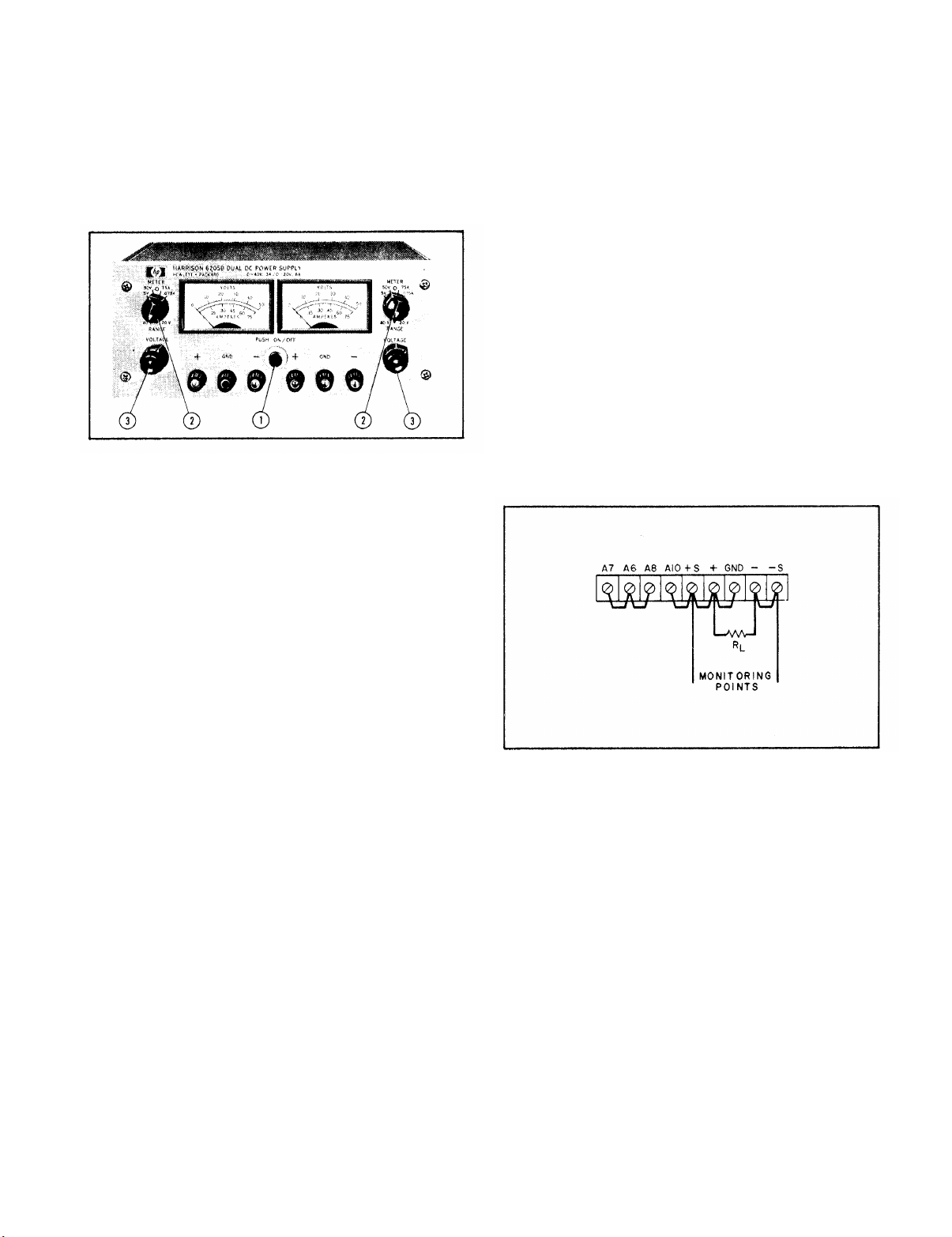
Front Panel Controls and Indicators 3-1
Normal Strapping Pattern
Current Limit Alteration
Remote Resistance Programming 3-3
Remote Voltage Programming
Remote Sensing 3-3
Norma I Series Connections 3-4
Auto-Series, Two and Three Units 3-4
Auto-Parallel, Two and Three
Units
Auto-Tracking, Two and Three
Units 3-5
Overa11 Block Diagram 4-1
3-1
3-2
3-3
3-5
LIST OF TABLES
Figure
4-2
5-1
5-2
5-3
5-4
5-5
5-6
5-7
5-8
5-9
5-10
5-11
Page No.
Multiple Range Meter Circuit,
Simplified Schematic
Front Panel Terminal Connections 5-1
Output Current Measurement
Technique
Differential Voltmeter Substitute,
Test Setup
Output Current, Test Setup 5-4
Load Regulation, Test Setup
CV Ripple and Noise, Test Setup 5-5
CV Noise Spike, Test Setup
Transient Recovery Time,
Test Setup
Transient Recovery Time,
Waveforms
Output Impedance, Test Setup
Servicing Printed Wiring Boards
4-4
5-1
5-2
5-4
5-6
5-7
5-7
5-8
5-14
Table
1-1 Specifications
5-1 Test Equipment Required
5-2 Reference Circuit Troubleshooting
5-3 Overall Trouble shooting 5-9
5-4 High Output Voltage Troubleshooting
5-5 Low Output Voltage Troubleshooting
5-6 Selected Semiconductor Characteristics
5-7 Checks and Adjustments After Replacement of Semiconductor Devices 5-12
6-1 Reference Designators
6-2 Description Abbreviations
6-3 Code List of Manufacturers
6-4 Replaceable Parts
Page No.
1-3
5-2
5-9
5-11
5-11
5-12
6-1
6-1
6-2
6-5
iii
Page 6

SECTION O
INSTRUCTIONS
TM 11-6625-2965-14&P
0-1.
Model 6205) having serial prefix number 7L2301 and up. For serial prefixes
below 7L2301 refer to Appendix E.
inclusion of change page.
0-2.
whether there are new editions , changes, or additional publications pertain-
ing to the equipment.
modification work orders (MWO
0-3.
the Army forms and procedures used for equipment maintenance will be those
described by TM 38-750, The Army Maintenance Management System,
DD Form 6 (Packaging Improvement Report) as prescribed in AR 700-58/
NAVSUPINST 4030.29/AFR 71-12/MCO P4030.29A, and DLAR 4145.8.
SCOPE
This manual applies directly to Power Supply PP-7548/U (Hewlett-Packard
For serials above 7L4450 check for
INDEXES OF PUBLICATIONS
DA Pam 310-4.
a.
b.
DA Pam 310-7.
MAINTENANCE FORMS, RECORDS AND REPORTS
a.
Reports of Maintenance and Unsatisfactory Equipment.
b.
Report of Packaging and Handling Deficiencies.
Refer to the latest issue of DA Pam 310-4 to determine
Refer to DA Pam 310-7 to determine whether there are
S
) pertaining to the equipment.
Department of
Fill out and forward
c.
Discrepancy in Shipment Report (DISREP) (SF 361). Fill out and
forward Discrepancy in Shipment Report (DISREP) (SF 361) as prescribed in
AR 55-38/NAVSUPINST 4610.33B/AFR 75-18/MCO P461O.19C and DLAR 4500.15.
0-4.
Send us an EIR.
don’t like about your equipment.
Tell us why a procedure is hard to perform.
Deficiency Report).
Electronics Materiel Readiness Command and Fort Monmouth, ATTN: DRSEL-ME-
MQ, Fort Monmouth, New Jersey 07703. We'll send yOu a reply.
0-5.
shall be in accordance with paragraph 2-5.
0-6.
accordance with TM 750-244-2.
REPORTING EQUIPMENT IMPROVEMENT RECOMMENDATIONS(EIR)
If your Power Supply PP-7548/U (HP-6205) needs improvement, let us know.
You, the user,
Mail it to Commander, US Army Communications and
ADMINISTRATIVE STORAGE
Administrative storage of equipment issued to and used by Army activities
DESTRUCTION OF ARMY ELECTRONICS MATERIEL
Destruction of Army electronics materiel to prevent enemy use shall be in
are the only one who can tell us what you
Let us know why you don’t like the design.
Put it on an SF 368 (Quality
0-1
Page 7
TM 11-6625-2965-14&P
1-1 DESCRIPTION
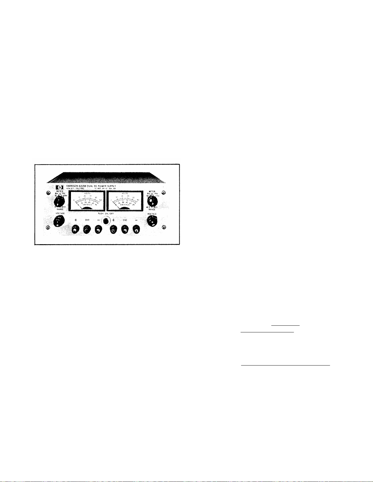
1-2
This power supply, Figure 1-1, is completely
transistorized and suitable for either bench or relay rack operations, The dual supply consists of
two independently controlled dual range sections;
both identical to the other. Each section can fur-
nish either a 0-40 Volt output at 300mA or a 0-20
Volt output at 600mA. Each section has its own
front panel meter and operating controls, The oper-
ating modes (40V or 20V) are selected by means of
the front panel RANGE switches, The VOLTAGE controls permit each output voltage to be continuously
adjusted throughout either output range.
may be programmed from a remote location by
means of an external voltage source or resistance.
b. Remote Sensing. The degradation in
regulation which would occur at the load because
of the voltage drop which takes place in the load
leads can be reduced by using the power supply in
the remote sensing mode of operation.
c. Series and Auto-Series Operation, Power
supplies may be used in series when a higher output voltage is required in the voltage mode of operation or when greater voltage compliance is required in the constant current mode of operation,
Auto-Series operation permits one knob control of
the total output voltage from a “master” supply.
d. Parallel and Auto-Parallel Operation, The
power supply may be operated in parallel with a
similar unit when greater output current capability
is required.
knob control of the total output current from a
“master” supply.
e. Auto-Tracking.
used as a “master” supply, having control over one
(or more) “slave”
ages for a system.
1-6 SPECIFICATIONS
Auto-Parallel operation permits one
The power supply may be
supplies that furnish various volt-
Figure 1-1. DC Power Supply, Model 6205B
1-3 Both sections of the supply are of the regulated, Constant Voltage/Current Limiting, type.
Each section is fully protected from overloads by
the fixed current limit which is set by means of an
internal adjustment.
1-4 Both front and rear terminals are available
for each section. Either the positive or negative
terminals may be grounded or the supply can be
operated at up to a maximum of 300 Volts off ground.
Each meter can be used to measure either output
voltage or output current in one of two ranges. The
voltage or current ranges are selected by the ap-
plicable METER switch on the front panel.
1-5 Two sets of programming terminals, located
at the rear of the unit, allow ease in adapting to
the many operational capabilities of the supply. A
brief description of these capabilities is given
below:
a, Remote Programming,
The power supply
1-7 Detailed specifications for the power supply
are given in Table 1-1.
1-8 OPTIONS
1-9 Options are factory modifications of a standard instrument that are requested by the customer.
The following options are available for the instru-
ment covered by this manual, Where necessary, de-
tailed coverage of the options is included through-
out the manual.
Option No.
07
11
Voltage 10-Turn Pot: A single control
that replaces both coarse and fine
voltage controls and improves output
nettability.
Overvoltage_Protection_“Crowbar”:
A completely separate circuit for protecting delicate loads against power
supply failure or operator error. This
independent device monitors the output voltage and within 10µsec imposes
a virtual short-circuit (crowbar) across
the power supply output if the preset
Description
11
Page 8

TM 11-6625-2965-14P
trip voltage is exceeded. When Option 11 is requested by the customer
the device is connected at the factory.
Trip Voltage Range: 2.5 to 44 Volts,
screwdriver adjustable.
Detailed coverage of Option 11 is included in Appendix A at the rear of
manuals that support power supplies
containing Option 11.
13
28
1-10 ACCESSORIES
1-11 The accessories listed in the following chart
may be ordered with the power supply or separately
from your local Hewlett-Packard field sales office
(refer to list at rear of manual for addresses).
Three Digit Graduated Decadial
Voltage Control: Control that replaces
coarse and fine voltage controls permitting accurate resettability.
230Vac Input:
shipped is wired for l15Vac input.
Option 28 consists of reconnecting
the input transformer for 230Vac operation.
Supply as normally
14523A
1-12 INSTRUMENT AND SERVICE MANUAL
IDENTIFICATION
1-13 Hewlett-Packard power supplies are identified by a three-part serial number tag. The first
part is the power supply model number. The second part is the serial number prefix, which consists of a number-letter combination that denotes
the date of a significant design change. The number designates the year, and the letter A through
L designates the month, January through December
respectively, with “I” omitted. The third part is
the power supply serial number.
1-14 If the serial number prefix on your power
supply does not agree with the prefix on the title
page of this manual, change sheets are included
to update the manual. Where applicable, backdating information is given in an appendix at the
rear of the manual.
ORDERING ADDITIONAL MANUALS
1-15
Rack Kit for mounting two 3½” high
supplies. (Refer to Section II for de-
tails.)
C05
14513A
Description
8” Black Handle that can be attach-
ed to side of supply.
Rack Kit for mounting one 3½” high
supply. (Refer to Section II for details.)
1-16
One manual is shipped with each power supply, Additional manuals may be purchased from
your local Hewlett-Packard field office (see list
at rear of this manual for addresses). Specify the
model number, serial number prefix, and Part
number provided on the title page.
1-2
Page 9

Table 1-1.
Specifications
TM 11-6625-2965-14&P
INPUT:
l15Vac ±10%, single phase, 48-440 Hz.
OUTPUT:
Two independent outputs, each of which can
be set at either 0-40 Volts @ 0.3 Amp or 0-20
Volts @ 0.6 Amp.
LOAD REGULATION:
Less than 0,01% plus 4mV for a full load to no
load change in output current.
LINE REGULATION:
Less than 0.01% plus 4mV for any line voltage
change within the input rating.
RIPPLE AND NOISE:
Less than 200µVrms 1mV p-p,
TEMPERATURE RANGES:
operating: 0 to 50°C. Storage: -40 to + 750C.
TEMPERATURE COEFFICIENT:
Less than 0.02% plus lmV per degree Centi-
grade.
STABILITY.
Less than 0.10% plus 5mV total drift for 8
hours after an initial warm-up time of 30 minutes at constant ambient, constant line voltage,
and constant load.
INTERNAL IMPEDANCE AS A CONSTANT VOLT-
AGE SOURCE:
Less than 0.02 ohms from dc to lkHz.
Less than 0.5 ohms from lkHz to 1OOkHz.
Less than 3.0 ohms from 1OOkHz to lMHz.
TRANSIENT RECOVERY TIME:
Less than 50µsec for output recovery to with-
in 10mV following a full load current change in
the output.
OVERLOAD PROTECTION:
A fixed current limiting circuit protects the
power supply for all overloads including a
direct short placed across the terminals in con-
stant voltage operation.
METERS:
Each front panel meter can be used as either a
0-50 or 0-5 Volt voltmeter or as a 0-0.75 or
0.075 Amp ammeter.
OUTPUT CONTROLS:
RANGE switches select desired operating mode
for each section and coarse and fine VOLTAGE
controls set desired output voltages.
OUTPUT TERMINALS:
Six “five-way” output posts (three for each
section of supply) are provided on the front
panel and two output terminal strips (one per
section) are located on the rear of the chassis.
A1l power supply output terminals are isolated
from the chassis and either the positive or negative terminals may be connected to the chassis
through separate ground terminals located on
the output termina1 strips.
ERROR SENSING:
Error sensing is normally accomplished at the
front terminals if the load is attached to the
front or at the rear terminals if the load is at-
tached to the rear terminals. Also, provisions
are included on the rear termina1 strips for remote sensing.
REMOTE RESISTANCE PROGRAMMING:
200 ohms per Volt.
REMOTE VOLTAGE PROGRAM MING:
1 Volt per Volt.
COOLING:
Convection cooling is employed. The supply
has no moving parts.
SIZE:
3~½" H x 12-5/8" D x 8½" W. Two of the units
can be mounted side by side in a standard 19”
relay rack.
WEIGHT:
10 lbs, net, 13 lbs. shipping.
FINISH:
Light gray front panel with dark gray case.
POWER CORD:
A three-wire, five-foot power cord is provided
with each unit.
1-3
Page 10
TM 11-6625-2965-14&P
SECTION II
INSTALLATION
2-1 INITIAL INSPECTION
2-2 Before shipment, this instrument was in-
spected and found to be free of mechanical and
electrical defects. As soon as the instrument is
unpacked,
occurred in transit. Save all packing materials
until the inspection is completed. If damage is
found, a claim should be filed with the carrier.
Hewlett-Packard Sales and Service office should
be notified.
2-3 MECHANICAL CHECK
2-4 This check should confirm that there are no
broken knobs or connectors, that the cabinet and
panel surfaces are free of dents and scratches,
and that the meter is not scratched or cracked.
2-5
inspect for any damage that may have
ELECTRICAL CHECK
2-6 The instrument should be checked against its
electrical specifications. Section V includes an
“ in-cabinet” performance check to verify proper
instrument operation,
2-7 INSTALLATION DATA
2-8 The instrument is shipped ready for bench
operation. It is necessary only to connect the instrument to a source of power and it is ready for
operation.
2-9 LOCATION
2-10 This instrument is air cooled. Sufficient
space should be allotted so that a free flow of
cooling air can reach the sides and rear of the in-
strument when it is in operation. It should be used
in an area where the ambient temperature does not
exceed 50°C.
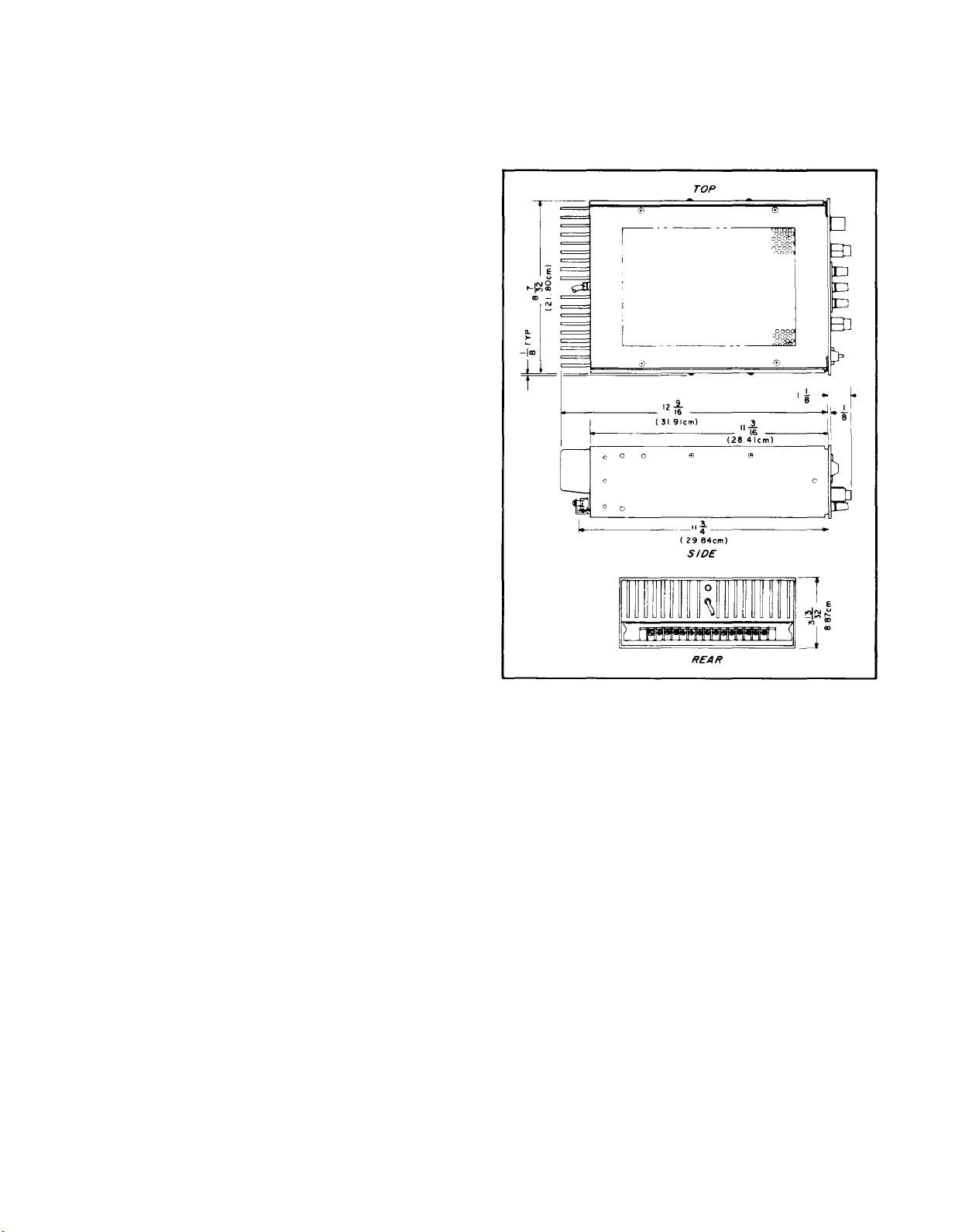
2-11 OUTLINE DIAGRAM
2-12 Figure 2-1 is an outline diagram showing the
dimensions of the instrument.
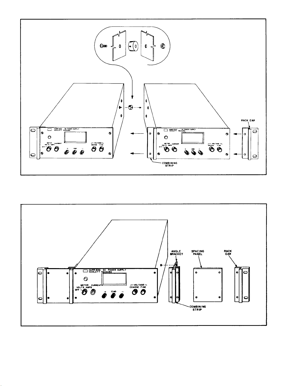
2-13 RACK MOUNTING
2-14 This instrument may be rack mounted in a
standard 19 inch rack panel either alongside a
similar unit or by itself. Figures 2-2 and 2-3 show
Figure 2-1. Outline Diagram
how both types of installations are accomplished.
2-15 To mount two units side-by-side, proceed
as follows:
a. Remove the four screws from the front
panels of both units.
b. Slide rack mounting ears between the
front panel and case of each unit.
c. Slide combining strip between the front
panels and cases of the two units.
d. After fastening rear portions of units together using the bolt, nut, and spacer, replace
panel screws.
2-16 To mount a single unit in the rack panel,
proceed as follows:
a. Bolt rack mounting ears, combining
straps, and angle brackets to each side of center
2-1
Page 11
TM 11-6625-2965-14&P
Figure 2-2. Rack Mounting, Two Units
Figure 2-3.
Rack Mounting, One Unit
Page 12
TM 11-6625-2965-14&P
spacing panels. Angle brackets are placed behind
combining straps as shown in Figure 2-3.
b. Remove four screws from front panel of
unit.
Slide combining strips between front
c.
panel and case of unit.
d. Bolt angle brackets to front sides of case
and replace front panel screws.
2-17 INPUT POWER REQUIREMENTS
2-18 This power supply may be operated from
either a nominal 115 Volt or 230 Volt 48-440 Hertz
power source. The unit, as shipped from the factory, is wired for 115 Volt operation. The input
power required when operated from a 115 Volt 60
Hertz power source at full load is 31 Watts and
0.35 Amperes.
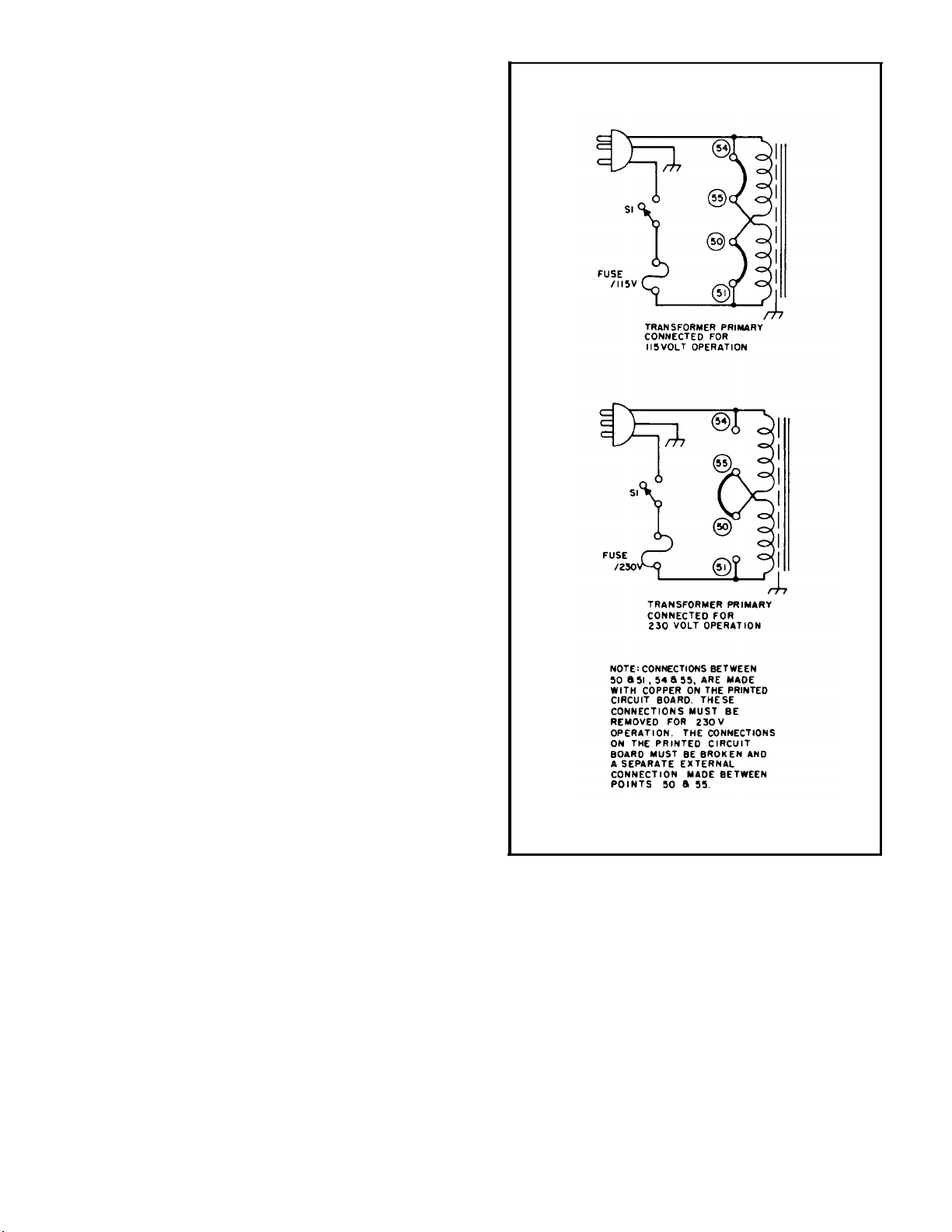
2-19 CONNECTIONS FOR 230 VOLT OPERATION
2-20 Normally, the two primary windings of the
input transformer are connected in parallel for operation from 115 Volt source. To convert the power
supply to operation from a 230 Volt source, the
power transformer windings are connected in series
as follows:
a.
Unplug the line cord and remove the unit
from case.
b. Break the copper between 54 and 55 and
also between 50 and 51 on the printed circuit
board. The se are shown in Figure 2-4, and are
labeled on copper side of printed circuit board.
Add strap between 50 and 55.
c.
d. Replace existing fuse with 1 Ampere,
230 Volt fuse.
normally.
Return unit to case and operate
2-21 POWER CABLE
2-22 To protect operating personnel, the National
Electrical Manufacturers Association (NEMA) recommends that the instrument panel and cabinet be
grounded. This instrument is equipped with a
three conductor power cable. The third conductor
is the ground conductor and when the cable is
plugged into an appropriate receptacle, the instrument is grounded. The offset pin on the power
cable three-prong connector is the ground connection.
2-23 To preserve the protection feature when operating the instrument from a two-contact outlet,
use a three-prong to two-prong adapter and connect the green lead on the adapter to ground.
2-24 REPACKAGING FOR SHIPMENT
2-25 To insure safe shipment of the instrument, it
is recommended that the package designed for the
Figure 2-4.
instrument be used. The original packaging material is reusable. If it is not available, contact
your local Hewlett-Packard field office to obtain
the materials. This office will also furnish the
address of the nearest service office to which the
instrument can be shipped. Be sure to attach a
tag to the instrument which specifies the owner,
model number, full serial number, and service re-
quired, or a brief description of the trouble,
2-3
Primary Connections
Page 13
SECTION Ill
OPERATING INSTRUCTIONS
TM 11-6625-2965-14&P
3-1 TURN-ON CHECKOUT PROCEDURE
Figure 3-1.
3-2 The front panel controls and indicators are
shown in Figure 3-1.
is described below:
A. Push ON/OFF button
that button lights,
B. Set range switch
mode and meter switch to desired voltage range.
C. Adjust coarse and fine voltage controls
Front Panel Controls and Indicators
The normal turn-on sequence,
① and observe
② to desired operating
③ until desired output voltage is indicated on
meter.
Set meter switch to highest current range
D.
and short
meter.
terminals
be used for both sections of supply.
circuit output terminals.
E.
Observe short circuit output current on
Remove short and connect load to output
F.
(front or rear),
For Model 6205B, this procedure should
G.
erational capabilities of the supply. A more theoretical description concerning these operational
features is contained in Application Note 90 and
in various Tech Letters. Copies of these can be
obtained from your local Hewlett-Packard field
office,
3-5 NORMAL OPERATING MODE
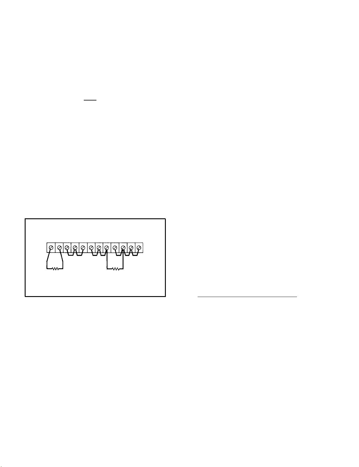
3-6 The power supply is normally shipped with
its rear terminal strapping connections arranged
for Constant Voltage/Current Limiting, local sensing, local programming, single unit mode of operation. This strapping pattern is illustrated in Figure 3-2. The operator selects a constant voltage
output using the front panel controls (local programming, no strapping changes are necessary).
Figure 3-2.
Norma 1 Strapping Pattern
3-3 OPERATING MODES
3-4 The power supply is designed so that its
mode of operation can be selected by making
strapping connections between particular terminals
on the terminal strip at the rear of the power supply.
The terminal designations are stenciled in
white on the power supply above their respective
terminals. Although the strapping patterns illustrated in this section show the positive terminal
grounded, the operator can ground either termina1
or operate the power supply up to 300Vdc off
ground (floating). The following paragraphs describe the procedures for utilizing the various op-
3-7 CONSTANT VOLTAGE
3-8 To select a constant voltage output turn on
the supply and, with no load connected, adjust
the VOLTAGE controls for the desired output volt-
age. To check the current limit, connect an ex-
ternal ammeter across the output of the
turn the VOLTAGE controls fully clockwise, and
observe the reading.
adjusted to approximately 100mA above the current
rating of the supply.
is not compatible with the anticipated load requirements, the limit can be changed as outlined
in the following paragraphs.
3-1
The current limit is factory
If the existing current limit
supply,
Page 14
TM 11-6625-2965-14&P
3-9 CHANGING CURRENT LIMIT
3-10 The current limit can be varied by adjusting
resistor R81, located on the printed wiring board.
This adjustment procedure is described in Paragraph 5-74. In Models 6204B and 6206B, the current limit may be reduced to a value lower than
that attainable by adjusting R81, by adding an external resistor as shown in Figure 3-3. The approximate value of the external resistance (Rx) can
be determined by using the following equation
=1.75
R
X
I
E
where: I = the output current
E
R = the internal current sampling resist-
I
ance for the particular operating mode
to be used.
1.75 . the approximate voltage drop across
the internal sampling resistance at
the current limit crossover point.
NOTE
The power supply’s performance will
be somewhat degraded if it is operated
too close to (within 10OmA) the current
limit crossover point.
3-13 If load considerations require that the output
power distribution terminals be remotely located
from the power supply, then the power supply output terminals should be connected to the remote
distribution terminals via a pair of twisted or
shielded wires and each load separately connected
to the remote distribution termina1s. For this case,
remote sensing should be used (Paragraph 3-25).
3-14 OPERATION BEYOND NORMAL RATED OUTPUT
3-15 Although the supply can deliver greater than
the rated output on both the lower and higher voltage ranges without being damaged, it can not be
guaranteed to meet all of its performance specifications.
Generally when operating the supply in
this manner, the output is unstable when connected to a load.
When greater than the lower rated
voltage is required, the higher voltage range
should be used.
This range will deliver half as
much output current and all specifications will
apply as listed in Table 1-1. However, if the line
voltage is maintained above its nomina1 value, the
supply will probably operate within specifications
above its rated output.
3-16 OPTIONAL OPERATING MODES
3-17 REMOTE PROGRAMMING, CONSTANT VOLTAGE
A1 A2 A6 A7 A8 A9 -S – GND + +S A10
Rx
Figure 3-3.
Current Limit Alteration
R
L
3-11 CONNECTING LOAD
3-12 Each load should be connected to the power
supply output terminals using separate pairs of
connecting wires.
This will minimize mutual cou-
pling effects between loads and will retain full
advantage of the low output impedance of the power
supply.
Each pair of connecting wires should be
as short as possible and twisted or shielded to reduce noise pickup. (If shield is used, connect one
end to power supply ground terminal and leave the
other end unconnected. )
3-18 The constant voltage output of the power
supply can be programmed (controlled) from a remote location if required. Either a resistance or
voltage source can be used for the programming
device.
The wires connecting the programming
terminals of the supply to the remote programming
device should be twisted or shielded to reduce
noise pickup. The VOLTAGE controls on the front
panel are disabled according to the following pro-
cedures.
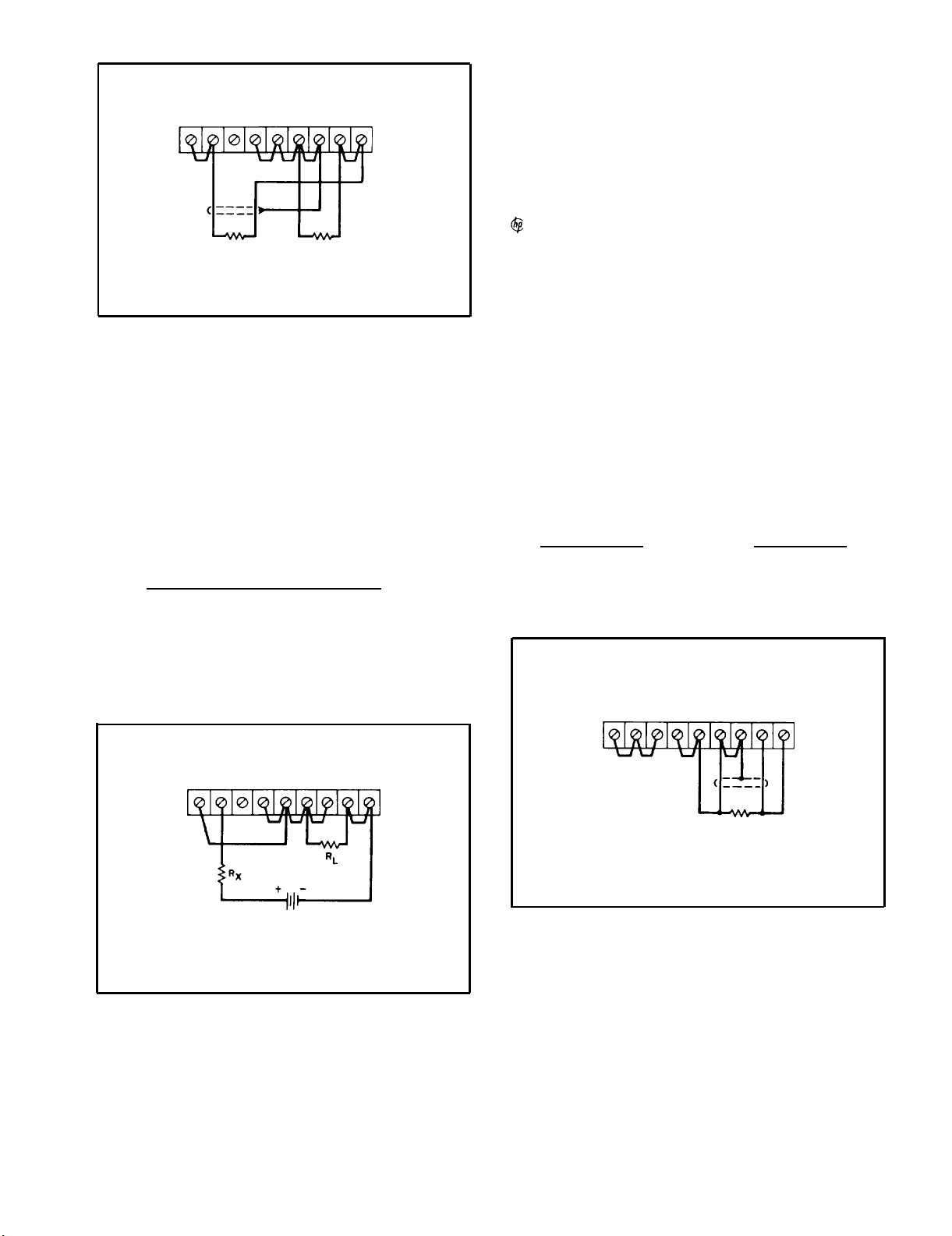
3-19 Resistance Programming (Figure 3-4). In
this mode, the output voltage will vary at a rate
determined by the programming coefficient (200
ohms per Volt for Model 6204B and 6205B or 300
ohms per Volt for Model 6206 B). The output voltage will increase by 1 Volt for each 200 ohms (or
300 ohms) added in series with the programming
terminals. The programming accuracy is 1% of the
programmed voltage. If greater programming ac-
curacy is required, it may be achieved by chang-
ing resistor R13 as outlined in Section V.
3-20 The output voltage of the power supply
should be zero Volts ± 20 millivolts when zero
ohms is connected across the programming terminals. If a zero ohm voltage closer than this is required, it may be achieved by changing resistor
R6 or R8 as described in Section V.
3-2
Page 15
A7 A6 A8 A10+S + GND - –S
Figure 3-4.
PROGRAMMING
RESISTOR
Remote Resistance Programming
R
L
3-21 To maintain the stability and temperature
coefficient of the power supply, u se programming
resistors that have stable, low noise, and low
temperature (less than 30ppm per degree Centigrade) characteristics. A switch can be used in
conjunction with various resistance values in
order to obtain discrete output voltages.
The
switch should have make-before-break contacts
to avoid momentarily opening the programming
terminals during the switching interval.
TM 11-6625-2965-14&P
programming voltage source should be approximately 1000 ohms if the temperature and stability
specifications of the power supply are to be maintained. The programming accuracy is 1% of the
programmed voltage.
3-24 Methods of voltage programming with gain
are discussed in Application Note 90, Power Supply
Handbook; available at no charge from your local
Sales Office.
3-25 REMOTE SENSING (See Figure 3-6)
3-26 Remote sensing is used to maintain good
regulation at the load and reduce the degradation
of regulation which would occur due to the voltage
drop in the leads between the power supply and
the load. Remote sensing is accomplished by uti-
lizing the strapping pattern shown in Figure 3-6.
The power supply should be turned off before
changing strapping patterns. The leads from the
+S terminals to the load will carry less than 10
milliamperes of current, and it is not required that
these leads be as heavy as the load leads. However, they must be twisted or shielded to minimize
noise pick-up.
CAUTION
3-22 Voltage Programming (Figure 3-5). Employ
the strapping pattern shown on Figure 3-5 for
voltage programming.
In this mode, the output
voltage will vary in a 1 to 1 ratio with the pro-
gramming voltage (reference voltage) and the load
on the programming voltage source will not exceed
25 microampere.
A7 A6 A8 A10 +S + GND - -S
REFERENCE
VOLTAGE
Figure 3-5. Remote Voltage Programming
3-23 The impedance (Rx) looking into the external
Observe polarity when connecting the
sensing leads to the load.
A7 A6 A8 A10+S + AND– –S
R
L
Figure 3-6. Remote Sensing
3-27 For reasonable load lead lengths, remote
sensing greatly improves the performance of the
supply. However, if the load is located a consid-
erable distance from the supply, added precautions
must be observed to obtain satisfactory operation.
Notice that the voltage drop in the load leads sub-
3-3
Page 16
TM 11-6625-2965-14&P
tracts directly from the available output voltage
and also reduces the amplitude of the feedback error signals that are developed within the unit. Because of these factors it is recommended that the
drop in each load lead not exceed 1 Volt. If a
larger drop must be tolerated, please consuIt a
sales
engineer.
NOTE
Due to the voltage drop in the load
leads, it may be necessary to readjust
the current limit in the remote sensing
mode.
3-28
Another factor that must be considered is
the inductance of long load leads which could affect the stability of the feedback loop and cause
oscillation. In these cases, it is recommended
that the output capacitor (C20) be physically removed from the power supply and placed across
the output terminals.
3-29 Although the strapping patterns shown in
Figures 3-4 and 3-5 employ local sensing, notice
that it is possible to operate a power supply simultaneously in the remote sensing and the remote
programming modes.
ages of the individual supplies. Each of the individual supplies must be adjusted in order to obtain
the total output voltage. The power supply contains a protective diode connected internally
across the output which protects the supply if one
power supply is turned off while its series partner(s) is on.
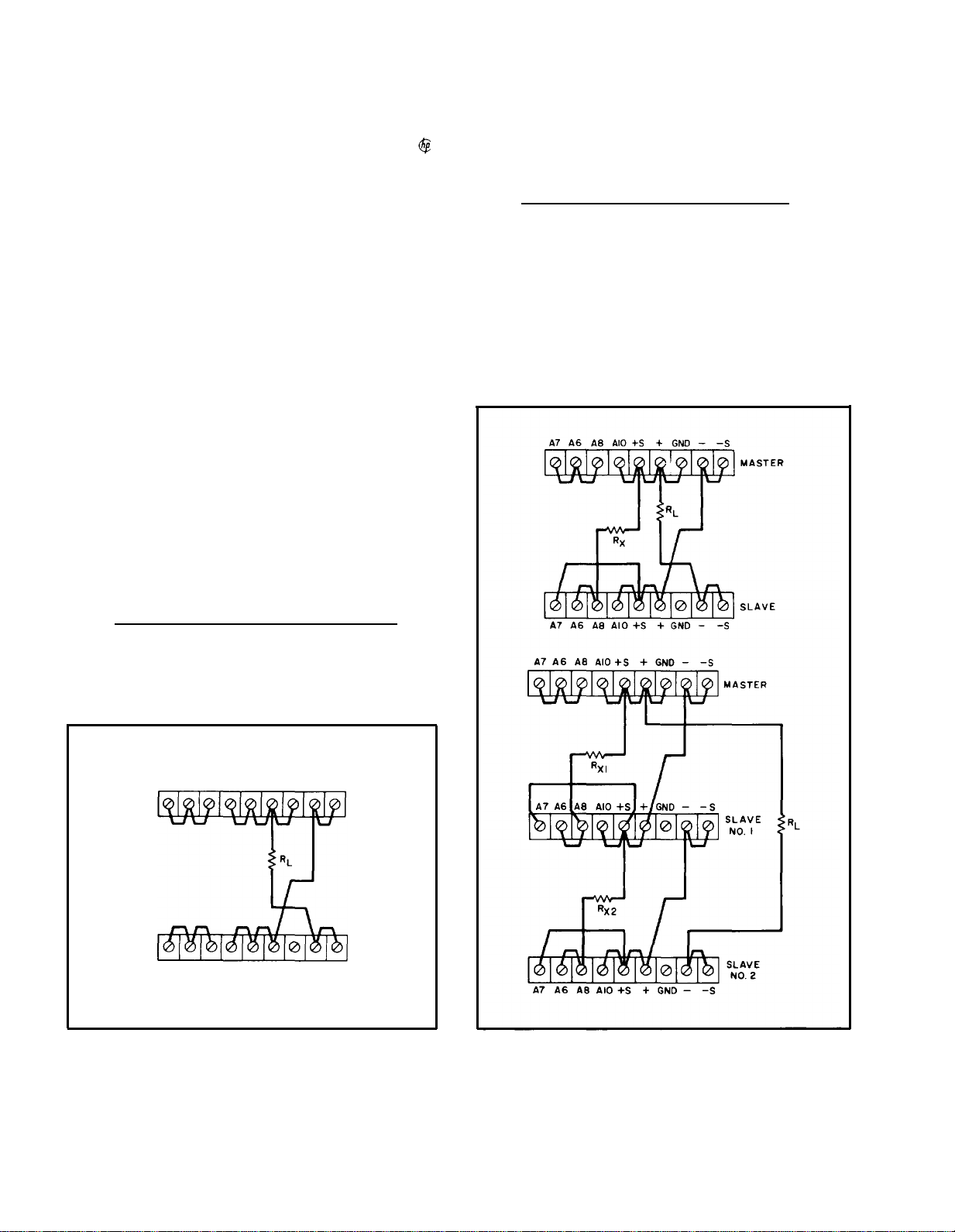
3-32 Auto-Series Connections (Figure 3-8). The
Auto-Series configuration is used when it is desirable to have the output voltage of each of the
series connected supplies vary in accordance with
the setting of a control unit. The control unit is
called the master; the controlled units are called
slaves. At maximum output voltage, the voltage
of the slaves is determined by the setting of the
front panel VOLTAGE control on the master. The
master supply must be the most positive supply of
the series.
The current limit settings of all series
3-30 SERIES OPERATION
3-31 Normal Series Connections (Figure 3-7).
Two or more power supplies can be operated in
series to obtain a higher voltage than that available from a single supply. When this configuration
is used, the output voltage is the sum of the volt-
A7 A6 A8 A10-S + GND – –S
A7 A6 A8 A10 - S + GND – –S
Figure 3-7. Normal Series Connections
Figure 3-8, Auto-Series, Two and Three Units
3-4
Page 17
units are effective and the current limit for the
entire configuration is equal to the lowest current
limit setting. If any of the settings are too low,
automatic crossover to current limiting operation
will occur and the output voltage will drop. Re-
mote sensing and programming can be used; however, the strapping arrangements shown in the applicable figures show local sensing and programming.
3-33 In order to maintain the temperature coeffi-
cient and stability specifications of the power
supply, the external resistors (Rx) shown in Figure
3-8 should be stable, low noise, low temperature
coefficient (less than 30ppm per degree Centigrade)
resistors. The value of each resistor is dependant
on the maximum voltage rating of the master sup-
ply,
The value of Rx is this voltage divided by the
voltage programming current of the slave supply
(l/Kp where Kp is the voltage programming coeffi-
cient). The voltage contribution of the slave is
determined by its voltage control setting.
TM 11-6625-2965-14&P
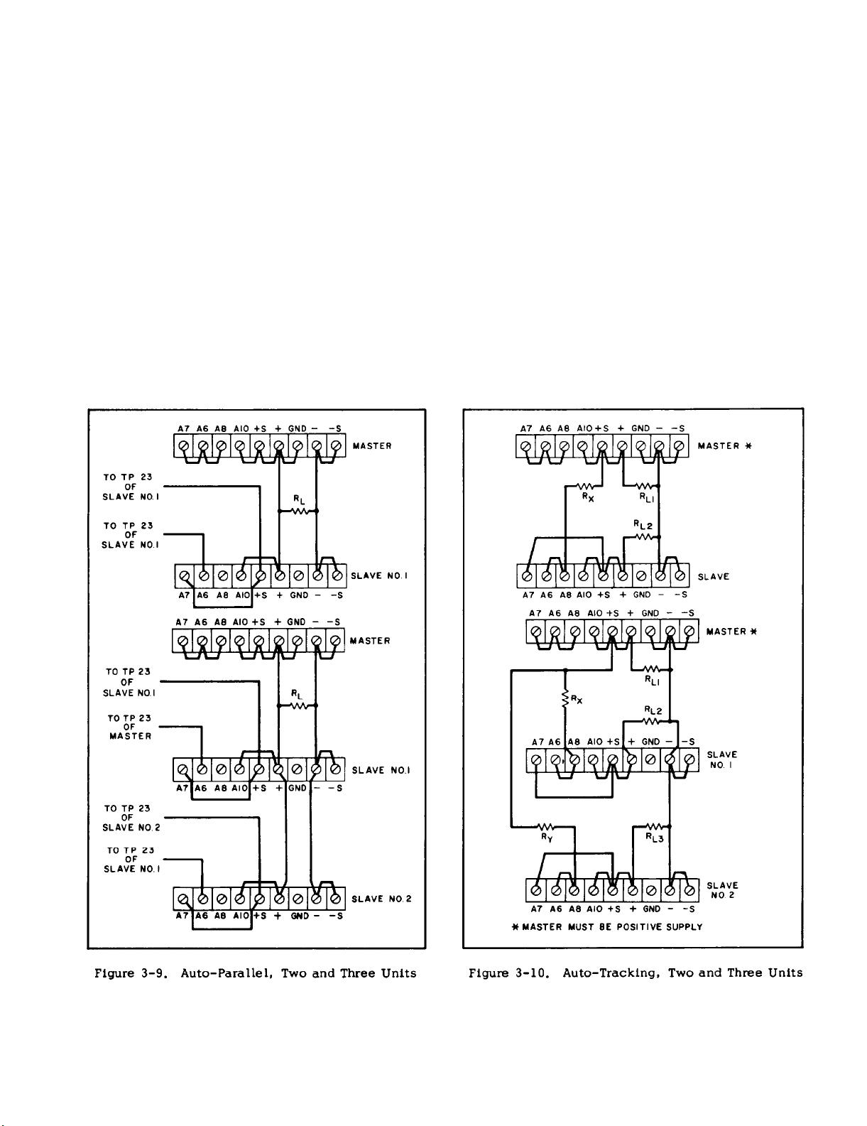
3-34 Auto-Parallel. The strapping patterns for
Auto-Parallel operation of two and three
plies are shown in Figure 3-9. Auto-Parallel operation permits equal current sharing under all load
conditions, and allows complete control of the output current from one master power supply. The output current of each slave will be approximately
equal to the master’s regardless of the load conditions. Because the output current controls of each
slave are operative, they should be set to maximum
to avoid having the slave revert to constant current
operation; this would occur if the master output
current setting exceeded the slave’s. In Model
6205B, it is necessary to make internal connections
in order to operate the supply in this mode. The
internal connections, specified in Figure 3-9,
made to the sampling terminals of the current sam-
pling terminals of the current sampling resistor,
R54 (see Figure 5-2).
power sup-
are
3-5
Page 18

TM 11-6625-2965-14&P
3-35 AUTO-TRACKING OPERATION (See Figure 3-10)
3-36 The Auto-Tracking configuration is used
when it is necessary that several different voltages
referred to a common bus, vary in proportion to the
setting of a particular instrument (the control or
master).
A fraction of the master’s output voltage
is fed to the comparison amplifier of the slave supply, thus controlling the slave’s output. The master must have the largest output voltage of any
power supply in the group (must be the most posi-
tive supply in the example shown on Figure 3-10).
3-37 The output voltage of the slave is a percentage of the master’s output voltage, and is determined by the voltage divider consisting of R
Rx and R
supply, R
Y) and the voltage control of the slave
, where:
p
E
M RP
E = Rx+Rp
S
Turn-on and turn-off of the power supplies is controlled by the master.
Remote sensing and programming can be used; although the strapping patterns for these modes show only local sensing and
programming.
In order to maintain the temperature
coefficient and stability specifications of the pow-
er supply, the external resistors should be stable,
low noise, low temperature (less than 30ppm per
O
C) resistors.
3-38
SPECIAL OPERATING CONSIDERATIONS
X (or
not desired, set the preset limit for the peak requirement and not the average.
3-41 OUTPUT CAPACITANCE
3-42 An internal capacitor, acress the output terminals of the power supply, helps to supply highcurrent pulses of short duration during constant
voltage operation.
Any capacitance added exter-
nally will improve the pulse current capability, but
will decrease the safety provided by the current
limiting circuit.
A high-current pulse may damage
load components before the average output current
is large enough to cause the current limiting circuit to operate.
3-43 REVERSE VOLTAGE LOADING
3-44 A diode is connected across the output terminals.
Under normal operating conditions, the
diode is reverse biased (anode connected to negative terminal).
If a reverse voltage is applied to
the output terminals (positive voltage applied to
negative terminal), the diode will conduct, shunting current across the output terminals and limiting the voltage to the forward voltage drop of the
diode.
This diode protects the series transistors
and the output electrolytic capacitors.
3-45 REVERSE CURRENT LOADING
3-39 PULSE LOADING
3-40 The power supply will automatically cross
over from constant voltage to constant current operation in response to an increase (over the preset
limit) in the output current, Although the
preset
limit may be set higher than the average output
current high peak currents (as occur in pulse loading) may exceed the preset current limit and cause
crossover to occur.
If this crossover limiting is
3-46 Active loads connected to the power supply
may actually deliver a reverse current to the power
supply during a portion of its operating cycle. An
external source cannot be allowed to pump current
into the supply without loss of regulation and possible damage to the output capacitor.
To avoid
these effects, it is necessary to preload the supply with a dummy load resistor so that the power
supply delivers current through the entire operating cycle of the load device.
3-6
Page 19
SECTION IV
PRINCIPLES OF OPERATION
REFERENCE
REGULATOR
CIRCUIT
TM 1 I-6625-2965-14&P
t
AC
INPuT TRANSFORMER
POWER
NOTE
— DENOTES VOLTAGE
— DENOTES CURRENT
FEEOBACK PATH VOLTAGE
LIMIT PATH
I
~o
Pm
RANGE
SWITCH
(s2)
BIAS
SUPPLY
RECTIFIER
AND
FILTER
Figure 4-1.
IAS
B
v
VOLTAGES
SERIES
REGULATOR
A
DRIVER
AMPL
Overall Block Diagram
CURRENT
LIMITING
CIRCUIT
+
4
*
CURRENT
sAMPLING
RESISTORS
CONSTANT
INPUT
CIRCUIT
CIRCUIT
P/o
2
4
4
4
4
4
1,
Q
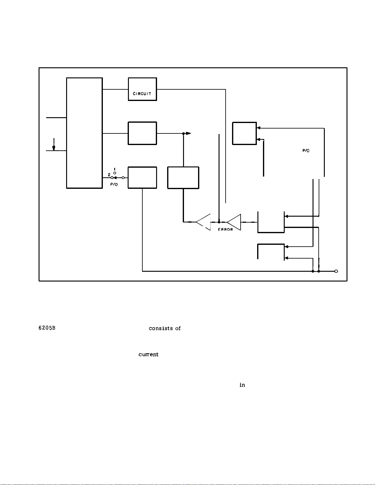
4-1 OVERALL DESCRIPTION
4-2
Figure 4-1 shows one section of the Model
6205B
dual power supply. The supply
consistsof
two dual range sections; each identical to the
other. Each section consists ofa rectifier and fil-
ter, a series regulator, an error amplifier and driver,
a constant voltage input circuit, a
cument limiting
circuit, a reference regulator circuit, a bias supply,
and a metering circuit.
Since both sections of the
supply are identical, only one section is described
below.
4-3 The ac line voltage is first applied to the
power transformer, The tap for the appropriate
voltage range is selected by S2. The input is then
rectified and filtered. This raw dc is then fed to
the series regulator which alters its conduction to
obtain the proper regulated dc output voltage.
4-4 Any changes in output voltage are felt by
constant voltage comparator which compares a
portion of the output with a fixed reference volts ge.
If a difference exists, the comparator circuit sends
a n error signal to the series regulator via the error
amplifier and driver stages. This error signal
changes the conduction of the series regulator so
that a constant output voltage is maintained.
4-5 Changes
in output current are reflected in the
voltage drop across the current sampling resistor
network. If this voltage drop exceeds a preset
limit, the current limit transistor conducts, sending
a turn-down signal to the series regulator via the
driver. This signal changes the conduction of the
4-1
the
Page 20

TM 11-6625-2965-14&P
series regulator so that the output current is limited
to the proper value.
4-6 The reference circuit provides stable reference voltages used in the constant voltage comparator and current limit circuits. The bias circuit
provides the less critical bias voltages used in the
supply.
4-7 The meter circuit provides a continuous indi-
cation of output voltage or current in both ranges.
4-8 DETAILED CIRCUIT ANALYSIS
4-9 FEEDBACK LOOP
4-10 The feedback loop functions continuously to
keep the output voltage constant during normal op-
eration of the supply. For purposes of this discussion, assume that the output voltage instantane-
ously rises (goes positive) due to a variation in the
external load circuit. Note that the change may be
in the form of a slow rise in the output voltage or a
positive going ac signal. An ac signal is coupled
to summing point A6 through capacitor Cl and a dc
voltage is coupled to A6 through R 10.
4-11 The rise in output voltage causes the voltage
at A6 and thus the base of Q1A to decrease (go negative). Q1A now decreases its conduction and its
collector voltage rises. The positive going error
voltage is amplified and inverted by Q3 and fed to
the base of the series transistor(s) via emitter fol-
lower Q4. The negative going input causes the
series transistor(s) to decrease its conduction so
that it drops more of the line voltage, reducing the
output voltage to its original level.
4-12 If the external load resistance decreases to
a certain crossover point, the supply will operate
in the current limiting mode. In the current limit
mode, Q1O conducts sending a negative going,
turn-down signal to the series regulator via driver
Q4 .
4-13 SERIES REGULATOR
4-14 The series regulator consists of transistor
stage Q7 (and Q6 on Model 6206 B). The regulator
serves as a series control element by altering its
conduction so that the output voltage is kept constant and the current limit is never exceeded, The
conduction of the transistor(s) is controlled by the
feedback voltage obtained from driver Q4. Diode
CR11, connected across the regulator circuit, protects the series transistor(s) against reverse voltages that could develop across it during parallel or
auto-parallel operation if one supply is turned on
before the other.
4-15 CONSTANT VOLTAGE COMPARATOR
4-16 The circuit consists of the coarse and fine
programming resistors (Rl0A and R 10 B), and a differential amplifier stage (Ql and associated com-
ponents). Transistor Q1 consists of two transistors
housed in a single package. The transistors have
matched characteristics minimizing differential
voltages due to mismatched stages. Moreover,
drift due to thermal differentials is minimized,
since both transistors operate at essentially the
same temperature.
4-17 The constant voltage comparator continuously compares a fixed reference voltage with a portion of the output voltage and, if a difference ex-
ists, produces an error voltage whose amplitude
and phase is proportional to the difference.
error output is fed back to the series regulator,
through the (mixer) error and driver amplifiers. The
error voltage changes the conduction of the series
regulator which, in turn, alters the output voltage
so that the difference between the two input voltages applied to the differential amplifier is reduced
to zero.
voltage constant.
4-18 Stage Q1B of the differential amplifier is
connected to a common (+S) potential through impedance equalizing resistor R5. Resistors R6 and
R8 are used to zero bias the input stage, offsetting minor base-to-emitter voltage differences in
Q1. The base of Q1A is connected to a summing
point at the junction of the programming resistors
and the current pullout resistors, R12 and R13.
Instantaneous changes in output voltage result in
an increase or decrease in the summing point potential. Q1A is made to conduct more or less, in
accordance with summing point voltage change.
The resultant output error voltage is fed back to
the series regulator via the remaining components
of the feedback loop.
the base Q1A, limits the current through the pro-
gramming resistors during rapid voltage turn-down.
Diodes CR1 and CR2 form a limiting network which
prevent excessive voltage excursions from over
driving stage Q1A.
programming resistors, increases the high frequency gain of the input amplifier. Resistor R1 3, shunt-
ing pullout resistor R12, is factory selected so
that all of the + 6.2 Volt reference is dropped across
R12 and R13. Linear constant voltage programming
is assured with a constant current flowing through
R1O.
removed to avoid current surges and increase the
programming speed.
4-19 ERROR AMPLIFIER AND DRIVER
4-20 The error and driver amplifiers amplify the
error signal from the constant voltage comparator
circuit to a leve1 sufficient to drive the series
regulator transistor(s).
current limiting input if Q10, the current limiting
transistor, conducts.
The above action maintains the output
Resistor Rl, in series with
Capacitor Cl, shunting the
C20 stabilizes the feedback loop and may be
Driver Q4 also receives a
The
4-2
Page 21

4-21 Stage Q3 contains a feedback equalizer network, C5 and R30, which provides for high frequency roll off in the loop gain in order to stabilize
the feedback loop. Q17 establishes a stable emitter bias potential for error amplifier Q3. Emitter
follower transistor(s) Q4 (and Q5) serves as the
driver (and predriver) element for the series regula-
tor.
4-22 CURRENT LIMIT CIRCUIT
4-23 The current limit circuit limits the output
current to a preset value determined by the setting
of R81. Switch S2B selects the proper sampling
resistance to maintain an equal voltage drop acress
the current sampling network in both ranges.
TM 11-6625-2965-14&P
4-28 The reference circuit consists of series regulating transistor Q9 and error amplifier Q8. Output voltage changes are detected by Q8 whose base
is connected to the junction of a voltage divider
(R41, R42) connected directly across the supply.
Any error signals are amplified and inverted by Q8
and applied to the base of series transistor Q9.
The series element then alters its conduction in the
direction, and by the amount, necessary to maintain the voltage across VR1 and VR2 constant. Resistor R46, the emitter resistor for Q8, is connected
in a manner which minimizes changes in the refer-
ence voltage caused by variations in the input line.
Output capacitor C9 stabilizes the regulator loop.
4-29 METER CIRCUIT (Figure 4-2)
4-24 When S2 is set to the 20 Volt position, R54
and R55 are connected in parallel. When S2 is set
to the 40 Volt position, the current sampling network consists solely of R54. Note that in the
twenty Volt range, twice as much current can be
delivered as in the forty Volt range. Since the
twenty Volt range has a sampling resistance equal
to half the value of that for the forty Volt range, an
equal sampling resistor voltage drop is obtained in
both ranges. This also applies to S2 in the 6206B.
4-25 R81 sets the bias of Q10, and thus, the
threshold point at which Q10 conducts and current
limiting begins. If this threshold is exceeded, Q10
begins to conduct, forward biasing CR16 and send-
ing a turn-down signal to the series regulater via
the driver. If the current through the current sampling network decreases below the threshold point,
Q10 turns off and no longer affects the operation of
the supply.
4-26 REFERENCE CIRCUIT
4-27 The reference circuit (see schematic) is a
feedback power supply similar to the main supply.
It provides stable reference voltages which are
used throughout the unit. The reference voltages
are a 11 derived from smoothed dc obtained from the
full wave rectifier (CR22 and CR23) and filter capacitor C10. The +6.2 and -6.2 voltages, which are
used in the constant voltage input circuit for comparison purposes, are developed across temperature
compensated Zener diodes VR1 and VR2. Resistor
R43 limits the current through the Zener diodes to
establish an optimum bias level.
4-30 The meter circuit provides continuous indications of output voltage or current on a single
multiple range meter.
The meter can be used either
as a voltmeter or an ammeter depending upon the
position of the METER section of switch S2 on the
front panel of the supply. This switch also selects
one of two meter ranges on each scale. The meter
circuit consists
of METER-RANGE switch S2, vari-
ous multiplying resistors and the meter movement.
4-31 When measuring voltage, the meter is placed
directly across the output of the supply between
the +S and -S terminals. With the METER section
of S2A in the higher voltage position (terminals A2
and A10) multiplying resistors R60, R61, R72, and
the parallel combination of R73 and R87, are in
series with the meter. For low output voltages, the
METER switch S2A can be set to the first position
(terminals 1 and 9) which removes R61 from its
series position allowing a larger percentage of the
output voltage to be felt acress the meter.
4-32 When measuring current; the meter circuit is
connected across the current sampling resistor
network as shown on Figure 4-2 and indicates the
output current that flows through the network. The
RANGE section S2B connects the appropriate re-
sistance in series with the meter so that its maxi-
mum deflection range is full-scale in the high current (low voltage) operating mode and half-scale in
the low current (high voltage) operating mode. This
circuit obviates the need for a dual current scale
which would be necessary since the voltages drop-
ped across the current sampling network in both
operating modes are equal for proportional currents.
4-3
Page 22

TM 11-6625-2965-14&P
Figure 4-2.
Multiple Range Meter Circuit, Simplified Schematic
4-4
Page 23

SECTION V
MAINTENANCE
5-1 INTRODUCTION
5-2 Upon receipt of the power supply, the per-
formance check (Paragraph 5-10) should be made.
This check is suitable for incoming inspection. If
a fault is detected in the power supply while making the performance check or during normal operation, proceed to the troubleshooting procedures
(Paragraph 5-48). After troubleshooting and repair
(Paragraph 5-58), perform any necessary adjustments and calibrations (Paragraph 5-60). Before
returning the power supply to normal operation,
repeat the performance check to ensure that the
fault has been properly corrected and that no other
faults exist. Before doing any maintenance checks,
turn-on power supply, allow a ha if-hour warm-up,
and read the general information regarding meas-
urement techniques (Paragraph 5-3).
5-3
GENERAL MEASUREMENT TECHNIQUES
Figure 5-1.
TM 11-6625-2965-14&P
Front Pane1 Terminal Connections
5-4
The measuring device must be connected
across the sensing leads of the supply or as close
to the output terminals as possible when measur-
ing the output impedance, transient response, regulation, or ripple of the power supply in order to
achieve valid measurements. A measurement made
acress the load includes the impedance of the
leads to the load and such lead lengths can easily
have an impedance several orders of magnitude
greater than the supply impedance, thus invalidating the measurement.
5-5 The monitoring device should be connected
to the +S and -S terminals (see Figure 3-2) or as
shown in Figure 5-1. The performance characteristics should never be measured on the front termi-
nals if the load is connected across the rear termi-
nals. Note that when measurements are made at
the front terminals, the monitoring leads are con-
nected at A, not B, as shown in Figure 5-1. Fail-
ure to connect the measuring device at A will re-
sult in a measurement that includes the resistance
of the leads between the output terminals and the
point of connection.
Figure 5-2. Output Current Measurement Technique
5-6 For output current measurements, the current
sampling resistor should be a four-terminal resis-
tor. The four terminals are connected as shown in
Figure 5-2. In addition, the resistor should be of
the low noise, low temperature coefficient (less
than 30ppm/°C) type and should be used at no
more than 5% of its rated power so that its temperature rise will be minimized.
When using an oscilloscope, ground one ter-
5-7
minal of the power supply and then ground the case
of the oscilloscope to this same point. Make cer-
tain that the case is not also grounded by some
other means (power line). Connect both oscillo-
scope input leads to the power supply ground terminal and check that the oscilloscope is not exhibiting a ripple or transient due to ground loops,
pick-up, or other means.
5-1
Page 24

TM 11-6625-2965-14&P
5-8 TEST EQUIPMENT REQUIRED
5-9 Table 5-1 lists the test equipment required
to perform the various procedures described in this
Section.
NOTE
A satisfactory substitute for a differential voltmeter is to arrange a reference voltage source and null detector
as shown in Figure 5-3. The reference voltage source is adjusted so
that the voltage difference between
the supply being measured and the
reference voltage will have the re-
quired resolution for the measurement
being made. The voltage difference
will be a function of the null detector
that is used. Examples of satisfactory null detectors are: 419A null
detector, a dc coupled oscilloscope
utilizing differential input, or a 50mV
meter movement with a 100 division
scale. For the latter, a 2mV change in
voltage will result in a meter deflection of four divisions.
Figure 5-3. Differential Voltmeter Substitute,
Test Setup
CAUTION
Care must be exercised when using an
electronic null detector in which one
input terminal is grounded to avoid
ground loops and circulating currents.
TYPE
Differential
Voltmeter
Variable
Voltage
AC Voltmeter
Oscilloscope
Oscillator
DC Voltmeter
Table 5-1.
REQUIRED
CHARACTERISTICS
Sensitivity: lmV full scale
(min.). Input impedance:
10 megohms (min.).
Range: 90-130 Volts
Equipped with voltmeter accurate within 1 Volt.
Accuracy: 2%. Sensitivity:
lmV full scale deflection
(min.).
Sensitivity: 10µV/cm. Differential input.
Range: 5Hz to 600kHz
Accuracy: 2%
Accuracy: 1%. Input resistance: 20,000 ohms/Volt (min.).
Test Equipment Required
USE
Measure dc voltages;
calibration procedures
Vary ac input
Measure ac voltage and
ripple
Display transient response
waveforms
Impedance Checks
Measure dc voltages
RECOMMENDED
MODEL
3420 (See Note)
403 B
140 A plus
1402A plug in.
200 CD
412A
Repetitive
Load Switch
Rate: 60-400 Hz, 2µsec rise
and fall time.
Measure transient response
5-2
See Figure 5-6
Page 25

Table 5-1.
TM 11-6625-2965-14&P
Test Equipment Required (Continued)
TYPE
Resistor
Resistor Value: 5 , 0.5%, 4.5 Watts,
Resistor Value: 6204B and 6205B, 28 ,
Resister
Resistor
Resistor Value: See Paragraph 5-67.
Capacitor
Decade
Resistance
Box
6204B, 6205B; 133 , ± 10% 15W
6206B; 120 , ±1O% 15W
20ppm, 4-Terminal.
2W (min.).
6206B, 27 , 10W (min.).
1Κ ± 1%, 2 Watt non-induc- Measure impedance
tive
100 ohms, ±5%, 10 Watt Measure impedance
± 0.1%, 5 Watt
500µf, 50WVdc
Range: 0-150K (min.). Measure programming
Accuracy: 0.1% plus 1 ohm
Make-before-break contacts.
REQUIRED
CHARACTERISTICS
USE
Load Resistor, HIGH range
Current sampling
Load resistor, low range
Calibrate programming current
Measure impedance
coefficients
RECOMMENDED
MODEL
----
R54 or R55,
Section VI
----
----
----
----
----
----
5-10 PERFORMANCE TEST
5-11 The following test can be used as an incoming inspection check and appropriate portions of
the test can be repeated either to check the oper-
ation of the instrument after repairs or for periodic
maintenance tests. The tests are performed using
a 115Vac 60 Hz, single phase input power source.
If the correct result is not obtained for a particular check, do not adjust any controls; proceed to
troubleshooting (Paragraph 5-48).
NOTE
For Model 6205B supplies, the following performance checks should be
performed twice in order to check both
independent sections of the supply.
5-12 CONSTANT VOLTAGE TESTS
5-13 For Constant Voltage measurements, the
measuring device must be connected acress the
rear sensing terminals of the supply in order to
achieve valid indications. A measurement made
acress the load includes the impedance of the
leads to the load and such lead lengths can easily
have an impedance several orders of magnitude
greater than the supply impedance (1 milliohm at
dc), thus invalidating the measurement.
5-14 To avoid mutual coupling effects, each
monitoring device must be-connected directly to
the sensing terminals by separate pairs of leads.
The load resistor is connected acress the output
terminals and must be selected according to the
output voltage and current of the supply. When
measuring the constant voltage performance spec-
ifications, the CURRENT controls should be set
well above the maximum output current which the
supply will draw, since the onset of constant cur-
rent action will cause a drop in output voltage,
increased ripple, and other performance changes
not properly ascribed to the constant voltage operation of the supply.
5-15 Voltage Output and Voltmeter Accuracy. To
check the output voltage, proceed as follows:
a. Connect 133 ohm load resistor (120 ohms
for Model 6206B) across rear output terminals of
supply.
b. Connect differential voltmeter acress +S
and -S terminals of supply observing correct polarity.
5-3
Page 26

TM 11-6625-2965-14&P
Set METER switch to highest voltage
c.
range and RANGE switch to highest voltage mode
and turn on supply.
d. Adjust VOLTAGE controls until front panel
meter indicates exactly the maximum rated output
voltage.
e. Differential voltmeter should indicate
maximum rated output voltage within 3%.
5-16 Output Current and Ammeter Accuracy. To
check the output current, proceed as follows:
a.
Connect test setup shown in Figure 5-4.
b.
Set METER switch to lowest current
range and RANGE switch to high voltage mode.
c.
Turn on supply and adjust VOLTAGE controls until front panel meter indicates exactly 300
mA (0.5 Ampere for Model 6206B supplies).
d. Differential voltmeter should read 1.5 ±
0.045Vdc.
ferential voltmeter.
e. Disconnect load resistors.
f.
Reading on differential voltmeter should
not vary from reading recorded in Step d by more
than 8mVdc for Models 6204B and 6205B or 10mVdc
for Model 6206B supply.
Figure 5-4.
Load Regulation.
5-17
Definition: The change
static value of dc output voltage resulting from a change in load resistance from open circuit to a value
which yields maximum rated output
current (or vice versa).
To check the constant voltage load regula-
5-18
proceed as follows:
tion,
a.
Connect test setup as shown in Figure
5-5.
b. Turn CURRENT controls fully clockwise.
c. Turn-on supply and adjust VOLTAGE con-
trols until front panel voltmeter indicates exactly
the maximum rated output voltage.
d. Read and record voltage indicated on dif-
Output Current, Test Setup
∆Ε in the
OUT
Figure 5-5.
5-19 Line Regulation.
Definition: The change,
static value of dc output voltage resulting from a change in ac input voltage over the specified range from low
line 10% less than nominal to high
line 10% more than nominal or from
high line to low line.
5-20 To test the constant voltage line regulation,
proceed as follows:
a. Connect variable auto transformer between input power source and power supply power
input.
b. Turn CURRENT controls fuIly clockwise.
c. Connect test setup shown in Figure 5-5.
d. Adjust variable auto transformer for low
line (104Vac).
e. Set METER switch to highest current
range and turn on supply.
f. Adjust VOLTAGE controls until front
panel voltmeter indicates exactly the maximum
rated output voltage.
Read and record voltage indicated on
9.
differential voltmeter.
h. Adjust variable auto transformer for high
line (126Vac).
Load Regulation, Test Setup
∆Ε in the
OUT
I
5-4
Page 27

Reading on differential voltmeter should
i.
not vary from reading recorded in Step g by more
than 8mVdc for Models 6204B and 6205B or 10mVdc
for Model 6206B.
Ripple and Noise.
5-21
Definition: The residual ac voltage
which is superimposed on the dc
output of a regulated power supply.
Ripple and noise may be specified
and measured in terms of its RMS
or (preferably) peak-to-peak value.
Ripple and noise measurement can be made at any
input ac line voltage combined with any dc output
voltage and load current within rating.
5-22 The amount of ripple and noise that is pres-
ent on the power supply output is measured either
in terms of the RMS or (preferably) peak-to-peak
value. The peak-to-peak measurement is particu-
larly important for applications where noise spikes
could be detrimental to a sensitive load, such as
logic circuitry.
The RMS measurement is not an
ideal representation of the noise, since fairly
high output noise spikes of short duration could
be present in the ripple and not appreciably increase the RMS value.
TM 11-6625-2965-14&P
5-23 The technique used to measure high frequency noise or “ spikes”
on the output of a power supply is more critical than the low frequency ripple
and noise measurement technique; therefore the
former is discussed separately in Paragraph 5-31,
5-24 Ripple and Noise Measurements. Figure
5-6A shows an incorrect method of measuring p-p
ripple. Note that a continuous ground loop exists
from the third wire of the input power cord of the
supply to the third wire of the input power cord of
the oscilloscope via the grounded power supply
case, the wire between the negative output terminal of the power supply and the vertical input of
the scope, and the grounded scope case. Any
ground current circulating in this loop as a result
of the difference in potential E
between the two
G
ground points causes an IR drop which is in series
with the scope input. This IR drop, normally hav-
ing a 60
HZ line frequency fundamental, plus any
pickup on the unshielded leads interconnecting
the power supply and scope, appears on the face
of the CRT. The magnitude of this resulting noise
signal can easily be much greater than the true
ripple developed between the plus and minus out-
put terminals of the power supply, and can com-
pletely invalidate the measurement.
5-25 The same ground current and pickup problems
Figure 5-6. CV Ripple and Noise, Test Setup
can exist if an RMS voltmeter is substituted in
place of the oscilloscope in Figure 5-6. However,
the oscilloscope display, unlike the true RMS
meter reading, tells the observer immediately
whether the fundamental period of the signal displayed is 8.3 milliseconds (1/120 Hz) or 16.7 milliseconds (1/60Hz). Since the fundamental ripple
frequency present on the output of an supply is
120Hz (due to full-wave rectification), an oscillo-
scope display showing a 120Hz fundamental component is indicative of a “clean” measurement setup, while the presence of a 60
HZ fundamental usu-
ally means that an improved setup will result in a
more accurate (and lower) value of measured ripple.
5-26 Although the method shown in Figure 5-6A is
not recommended for ripple measurements, it may
prove satisfactory in some instances provided certain precautionary measures are taken. One meth-
od of minimizing the effects of ground current flow
(IG) is to ensure that both the supply and the test
instrument are plugged into the same ac power
buss.
5-5
Page 28

TM 11-6625-2965-14&P
5-27 To minimize pick up, a twisted pair or (preferably) a shielded two-wire cable should be used
to connect the output terminals of the power supply
to the vertical input terminals of the scope. When
using a twisted pair, care must be taken that one
of the two wires is connected both to the grounded
terminal of the power supply and the grounded input terminal of the oscilloscope. When using
shielded two-wire cable, it is essential for the
shield to be connected to ground at one end only to
prevent any ground current flowing through this
shield from inducing a signal in the shielded leads.
5-28 To verify that the oscilloscope is not displaying ripple that is induced in the leads or pick-
ed up from the grounds, the (+) scope lead should
be shorted to the (-) scope lead at the power sup-
ply terminals. The ripple value obtained when the
leads are shorted should be subtracted from the
actual ripple measurement.
5-29 If the foregoing measures are used, the
single-ended scope of Figure 5-6A may be adequate
to eliminate non-real components of ripple so that
a satisfactory measurement can be obtained.
ever, in stubborn cases or in measurement situations where it is essential that both the power supply case and the oscilloscope case be connected
to ground (e. g. if both are rack-mounted), it may
be necessary to use a differential scope with floating input as shown in Figure 5-6B. If desired, two
single-conductor shielded cables may be substituted in place of the shielded two-wire cable with
equal success.
jection, a differential oscilloscope displays only
the difference in signal between its two vertical
input terminals, thus ignoring the effects of any
common mode signal introduced because of the difference in the ac potential between the power supply case and scope case. Before using a differential input scope in this manner, however, it is imperative that the common mode rejection capability
of the scope be verified by shorting together its
two input leads at the power supply and observing
the trace on the CRT.
line, the scope is properly ignoring any common
mode signal present.
line, then the scope is not rejecting the ground
signal and must be realigned in accordance with the
manufacturer’s instructions until proper common
mode rejection is attained.
Because of its common mode re-
If this trace is a straight
If this trace is not a straight
How-
5-31 Noise Spike Measurement. When a high frequency spike measurement is being made, an in-
strument of sufficient bandwidth must be used; an
oscilloscope with a bandwidth of 20 MHz or more
is adequate. Measuring noise with an instrument
that has insufficient bandwidth may conceal high
frequency spikes detrimental to the load.
5-32 The test setup illustrated in Figure 5-6A is
generally not acceptable for measuring spikes; a
differential oscilloscope is necessary. Furthermore, the measurement concept of Figure 5-6B
must be modified if accurate spike measurement
to be achieved:
1. As shown in Figure 5-7, two coax cables, must be substituted for the shielded twowire cable.
2. Impedance matching resistors must be
included to eliminate standing waves and cable
ringing, and the capacitors must be connected to
block the dc current path.
3. The length of the test leads outside the
coax is critical and must be kept as short as pos-
sible; the blocking capacitor and the impedance
matching resistor should be connected directly
from the inner conductor of the cable to the power
supply terminals.
4.
Notice that the shields of the power supply end of the two coax cables are not connected
to the power supply ground, since such a connection would give rise to a ground current path
through the coax shield, resulting in an erroneous
measurement.
Since the impedance matching resistors
5.
constitute a 2-to-1 attenuator, — the noise spikes
observed on the oscilloscope should be less than
0.5mV p-p instead of lmV.
5-33 The circuit of Figure 5-7 can also be used
for the normal measurement of low frequency ripple
and noise;
simply remove the four terminating re-
is
5-30 To check the ripple and noise output, proceed as follows:
a.
meter as shown in Figures 5-6A
meter indicates maximum rated output voltage.
less than 200µVrms and lmV p-p.
Connect the oscilloscope or RMS volt-
or 5-6B.
b. Adjust VOLTAGE control until front pane 1
c. The observed ripple and noise should be
5-6
Figure 5-7,
CV Noise Spike, Test Setup
Page 29

sisters and the blocking capacitors and substitute
a higher gain vertical plug-in in place of the wideband plug-in required for spike measurements.
Notice that with these changes, Figure 5-7 becomes a two-cable version of Figure 5-6C.
Transient Recovery Time.
5-34
Definition: The time “X” for output
voltage recovery to within “Y” mil-
livolts of the nominal output volt-
age following a “Z” Amp
step
change in load current - where:
“Y” is specified as 10 millivolts.
The nominal output voltage is defined as the dc level half way between the static output voltage
before and after the imposed load
change, and “Z” is the specified
load current change, which is 5
Amperes.
A mercury-wetted relay, as connected in the
5-35
load switching circuit of Figure 5-8 should be used
for loading and unloading the supply. When this
load switch is connected to a 60Hz ac input, the
mercury-wetted relay will open and close 60 times
per second. Adjustment of the 25K control permits
adjustment of the duty cycle of the load current
switching and reduction in jitter of the oscilloscope
display.
TM 11-6625-2965-14&P
cury-wetted relay contacts. Switching of larger
load currents can be accomplished with mercury
pool relays; with this technique fast rise times
can still be obtained, but the large inertia of mer-
cury pool relays limits the maximum repetition rate
of load switching and makes the clear display of
the transient recovery characteristic on an oscillo-
scope more difficult.
5-37 To check the transient recovery time of the
supply, proceed as follows:
a. Connect test setup shown in Figure 5-8.
b. Set METER switch to highest current
range and RANGE switch to lowest voltage mode.
Turn on supply and adjust VOLTAGE con-
c,
trols until front panel meter indicates exactly the
maximum rated output current.
d. Close line on repetitive load switch set-
up.
Adjust 25 potentiometer until a stable
e.
display is obtained on oscilloscope. Waveform
should be within the tolerances shown on Figure
5-9 (output should return to within 10mV of original
value in less than 50 microseconds).
5-36 The maximum load ratings listed in Figure
5-4 must be observed in order to preserve the mer-
Figure 5-8.
Transient Recovery Time, Test Setup
Figure 5-9. Transient Recovery Time, Waveforms
5-38 OUTPUT IMPEDANCE
5-39 To check the output impedance, proceed as
follows:
a. Connect test setup shown in Figure 5-10.
b. Set METER switch to highest voltage
range.
Turn on supply and adjust VOLTAGE con-
c.
trols until front panel meter reads 20 Volts.
d. Set AMPLITUDE control on oscillator to
10 Volts (E
), and FREQUENCY control to 100 Hz.
in
e. Record voltage across output terminals
of the power supply (E
) as indicated on ac volt-
o
meter.
f. Calculate the output impedance by the
5-7
Page 30

TM 11-6625-2965-14&P
following formula:
The output impedance (Z
g.
less than 0,020 ohms.
h. Using formula of Step f, calculate output
impedance at frequencies of 50kHz and 500kHz.
Values should be less than 0.5 ohm and 3.0 ohms,
respectively.
) should be
out
supply should be placed outside the oven and
should have a long term stability adequate to in-
sure that its drift will not affect the overall meas-
urement accuracy.
5-43 To check the temperature coefficient, proceed as follows:
a.
Connect test setup shown in Figure 5-5.
b. Turn CURRENT controls fully clockwise
and adjust front panel VOLTAGE controls until the
front panel voltmeter indicates 10Vdc.
c. Insert the power supply into the temperature-controlled oven (differential voltmeter and
load resistance remain outside oven). Set the
temperature to 30°C and aIlow 30 minutes warmup.
d. Record the differential voltmeter indication.
e.
Raise the temperature to 40°C and allow
30 minutes warm-up.
f. The differential voltmeter indication
should change by less than 90mV from indication
recorded in Step d.
5-44
Output Stability.
Definition: The change in output
voltage for the first eight hours
following a 30 minute warm-up
period. During the interval of
measurement all parameters,
such as load resistance, ambi-
ent temperature, and input line
voltage are held constant.
Figure 5-10. Output Impedence, Test Setup
5-40 Temperature Coefficient.
Definition: The change in output
voltage per degree Centigrade
change in the ambient temperature
under conditions of constant input
ac line voltage, output voltage
setting, and load resistance.
5-41 The temperature coefficient of
a power sup-
ply is measured by placing the power supply in an
oven and varying it over any temperature span
within its rating.
(Most power supplies are
rated for operation from 0°C to 55°C. ) The power
supply must be allowed to thermally stabilize for
a sufficient period of time at each temperature of
measurement.
5-42 The temperature coefficient specified is the
maximum temperature-dependent output voltage
change which will result over any 5°C interval.
The differential voltmeter or digital voltmeter
used to measure the output voltage change of the
5-45
This measurement is made by monitoring the
output of the power supply on a differential voltmeter or digital voltmeter over the stated measurement interval; a strip chart recorder can be used
to provide a permanent record. A thermometer
should be placed near the supply to verify that the
ambient temperature remains constant during the
period of measurement. The supply should be put
in a location immune from stray air currents (open
doors or windows, air conditioning vents); if pos-
sible, the supply should be placed in an oven
which is held at a constant temperature. Care
must be taken that the measuring instrument has a
stability over the eight hour interval which is at
least an order of magnitude better than the stabil-
ity specification of the power supply being measured. Typically, a supply may drift less over the
eight hour measurement interval than during the ½
hour warm-up period.
5-46 Stability measurement can be made while
the supply is remotely programmed with a fixed
wire-wound resistor, thus avoiding accidental
changes in the front panel setting due to mechan-
ical vibration or “knob-twiddling. “
5-8
Page 31
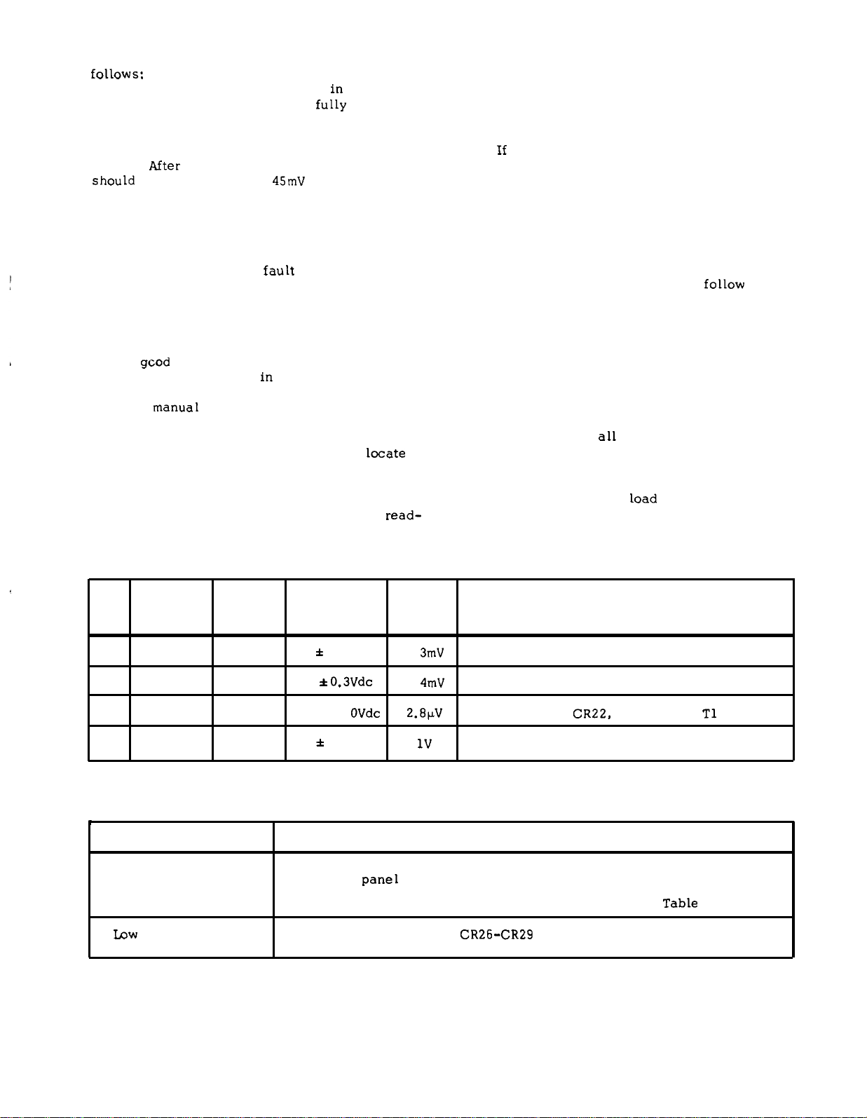
5-47 To check the output stability, proceed as
follows:
Connect test setup shown
a.
b. Turn CURRENT controls
in Figure 5-5.
fully
clockwise
and adjust VOLTAGE controls for 40Vdc output.
c. Allow 30 minutes warm-up then record
the differential voltmeter indication.
Mter
d.
should
change by less than
8 hours, differential voltmeter
45mV
from indication
recorded in Step c.
5-48 TROUBLESHOOTING
5-49 Before attempting to troubleshoot this in-
strument, ensure that the
fault
is with the instrument and not with an associated circuit. The performance test (Paragraph 5-10) enables this to be
determined without having to remove the instrument from the cabinet.
5-50 A
operation is a helpful aid
gcod understanding of the principles of
in troubleshooting, and
it is recommended that the reader review Section
IV of the
manua~
before attempting to troubleshoot
the unit in detail. Once the principles of operation are understood, refer to the overall trouble-
shooting procedures in Paragraph 5-53 to
locate
the symptom and probable cause.
5-51 The schematic diagram at the rear of the
manual (Figure 7-1) contains normal voltage
read-
TM 11-6625-2965-14&P
ings taken at various points within the circuits.
These voltages are positioned adjacent to the applicable test points (identified by encircled numbers). Component and test point designations are
marked directly on the main printed wiring board.
If
5-52
it and re-conduct the performance test. When a
component is replaced, refer to the repair and replacements and adjustment and calibration para-
graphs in this section.
5-53 OVERALL TROUBLESHOOTING PROCEDURE
5-54 To locate the cause of trouble follow Steps
1, 2, and 3 in sequence.
open fuse, defective power cord, input power fail-
ure, or defective voltage or current meter. Next
remove the top cover (held by four retaining
screws) and inspect for open connections, charred components, etc. If the trouble source cannot
be detected by visual inspection, proceed with
Step 2.
caused by improper dc bias or reference voltages;
thus, it is a good practice to check voltages in
Table 5-2, before proceeding with Step 3.
5-3 to determine your symptom and probable cause.
a defective component is located, replace
(1) Check for obvious troubles such as
all
(2) In almost
(3) Disconnect the
cases, the trouble can be
load and examine Table
STEP
1
2
3
4
v
METER METER
COMMON
+s
31
+s
38
SYMPTOM
High output voltage
Low
output voltage
POSITIVE
33
+s
37
41
Table 5-2. Reference Circuit Troubleshooting
NORMAL
INDICATION
6.2 * 0.3Vdc
6.2 + 0.3Vdc
12.4 *1.
OVdc
7.5 * .7Vdc
Table 5-3.
NORMAL
RIPPLE
(P-P)
.
3mV
.
4mV
2.8KV
IF INDICATION ABNORMAL, TAKE THIS ACTION
Check 12.4 Volt bias or VR1 (See next paragraph)
Check 12.4 Volt bias or VR2 (See next paragraph)
Check Q8, Q9, CR22, CR23, C1O,
lV Check C12, CR8, CR24, CR25
Overall Trouble shooting
CHECKS AND PROBABLE CAUSES
a. Front
panel
meter defective.
b. Series regulator feedback loop defective. Refer to
a. Fuses blown (Check
CR26-CR29 or C14 for short).
T1
Table 5-4.
5-9
Page 32

TM 11-6625-2965-14&P
Table 5-3. Overall Troubleshooting (Continued)
SYMPTOM
b. Front panel meter defective.
c. Series regulator feedback loop defective. Refer to Table 5-5.
Will not current limit
High ripple a. Check operating setup for ground loops.
Poor line regulation a.
Poor load regulation
(constant voltage)
Oscillates (constant a.
voltage)
a. Q10 open. R81 defective.
b. If output floating, connect lµf capacitor between output and ground.
Ensure that supply is not crossing over to current limit mode under
c.
loaded conditions.
Check reference circuit (Paragraph 5-55).
b. Check reference circuit adjustment (Paragraph 5-69).
a. Measurement technique. (Paragraph 5-17)
b. Check reference circuit (Paragraph 5-55) and adjustment (Para-
graph 5-69).
Ensure that supply is not going into current limit.
c.
Check C5 for open, adjustment of R30 (Paragraph 5-72).
CHECKS AND PROBABLE CAUSES
Poor stability
(constant voltage)
5-55 To check the zener diodes in the reference
circuit, proceed as follows:
a.
Connect differential voltmeter across
zener diode.
b. Connect appropriate load resistor, given
in Figure 5-4, across (+) and (-) output terminals.
c.
Turn VOLTAGE control fully clockwise.
d. Set METER switch to highest current
range and turn on supply.
e. Adjust CURRENT controls until panel
meter reads exactly the maximum rated output current.
f.
Read and record voltage indicated on dif-
ferential voltmeter.
Short out load resistor by closing S1.
g.
h. If reading on differential voltmeter differs by more than 1.07mV for 6204B and 6205B or
.946mV for 6206B from the reading in Step f, re-
place zener diode.
Check ± 6.2Vdc reference voltages (Paragraph 5-55).
a.
b. Noisy programming resistor R10.
c. CR1, CR2 leaky.
d. Check Rl, R12, R13, for noise or drift.
e. Stage Q1 defective.
5-5b Series Regulating Feedback Loop. When
troubleshooting the series regulating loop, it is
useful to open the loop since measurements made
anywhere within a closed loop may appear abnormal. With a loop closed, it is very difficult to
separate cause from effect. As described in
Tables 5-4 and 5-5, the conduction or cutoff ca-
pability of each stage is checked by shorting or
opening a previous stage, as follows:
Shorting the emitter to collector of a
1.
transistor simulates saturation, or the full ON
condition.
2. Shorting the emitter to base of a transis-
tor cuts it off, and simulates an open circuit be-
tween emitter and collector.
5-57 Although a logical first choice might be to
break the loop somewhere near its mid-point, and
then perform successive subdividing test, it is
5-10
Page 33

more useful to trace the loop from the series regulator backwards a stage at a time, since loop
Table 5-4. High Output Voltage Troubleshooting
TM 11-6625-2965-14&P
failures occur more often at the higher power
levels.
STEP
1
2
3
ACTION
Check turn off of series
regulator by shorting Q4
emitter to collector.
Check turn on of Q4 by
disconnecting collector
of Q3.
Check turn off of Q3 by
disconnecting collector
of Q1A.
RESPONSE
a. Output voltage
b. Output voltage
a. Output voltage remains high.
b. Output voltage decreases.
a. Output voltage remains high.
b. Output voltage decreases.
remains high.
decreases.
PROBABLE CAUSE
a. Series regulator Q7
(or Q6) shorted.
b. Remove short and proceed
to Step 2.
a. Q4 open.
b. Reconnect lead and pro-
ceed to Step 3.
a. Q3 shorted.
b, Check Q1A for short,
Q1B for open. Check for
open strap between A6
and A8.
open.
Check R10 for
STEP
1
2
3
Table 5-5.
ACTION
Check turn on of Q7
(and Q6, if included)
by opening the emitter
of Q4 .
Eliminate the current
limit circuit as a source
of trouble by discon-
necting the anode of
CR16.
Check turn off of Q4 by
shorting Q3 emitter to
collector.
Low Output Voltage Troubleshooting
RESPONSE
a. Output voltage remains low.
b. Output voltage increases.
a. Output voltage increases.
b. Output voltage remains low.
a. Output voltage remains low.
b. Output voltage increases.
5-11
PROBABLE CAUSE
a. Q7 (or Q6) open.
b. Reconnect lead and pro-
ceed to Step 2.
a. Q10 shorted, R81 defec-
tive.
b. Reconnect lead and pro-
ceed to Step 3.
a. Q4 shorted.
b. Remove the short and
proceed to Step 4.
Page 34
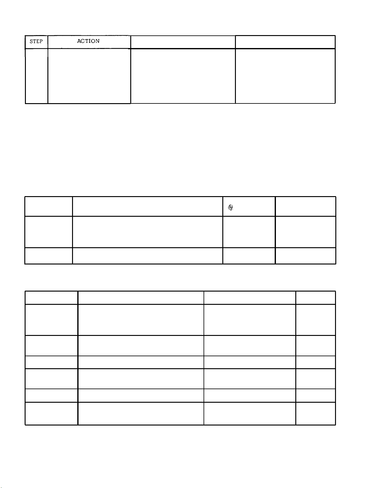
TM 11-6625-2965-14&P
Table 5-5. Output Voltage Troubleshooting (Continued)
4
5-58 REPAIR AND REPLACEMENT
5-59 Before servicing a printed wiring board, refer to Figure 5-11. Section VI of this manual con-
tains a tabular list of the instruments replaceable
parts. Before replacing a semiconductor device,
refer to Table 5-6 which lists the special charac-
REFERENCE
DESIGNATOR
Check turn on of Q3 by
shorting Q1A emitter to
collector
Table 5-6.
a.
Output voltage remains low
b. Output voltage increases
Selected Semiconductor Characteristics
CHARACTERISTICS
RESPONSE
teristics of selected semiconductors. If the device
to be replaced is not listed in Table 5-6, the
standard manufacturers part number listed in Sec-
tion VI is applicable. After replacing a semiconductor, refer to Table 5-7 for checks and adjustments that may be necessary.
PROBABLE CAUSE
a. Q3 open
b, Check Q1A for open, QlB
for short. Check R10 for
short or open strap be-
tween A7 and A6
STOCK NO.
SUGGESTED
REPLACEMENT
Q1
Q7
REFERENCE
Q1
Q3, Q4 Error amplifiers CV load regulation.
Q7 (Q6)
Q8, Q9 Reference regulator
CR1, CR2
Matched differential amplifier. NPN Si. planar
FE i
70 (min.) h
@ V
NPN Power hFE = 35 (min.) @ Ic = 4A; VCE = 4V.
Table 5-7.
=
cbo
5V,
Checks and Adjustments After Replacement of Semiconductor Devices
Constant voltage differential amplifier
Series regulater
Limiting diodes
= lmA, VCE = 5V, Ico = 0.01µA
c
FUNCTION CHECK
1854-0229 2N291 G.E.
1854-0225 2N3055 R. C,A,
Constant voltage (CV) line
and load regulation.
volt output.
CV transient response.
CV load regulation.
Reference circuit line
regulation.
CV load regulation.
Zero
ADJUST
R6 or R8
R30
VR1, VR2,
CR20
I
CR8
Forward bias regulator
Voltage across diode
2.0 to 2.4 Volts.
5-12
Page 35

TM 11-6625-2965-l4&P
Table 5-7.
Checks and Adjustments After Replacement of Semiconductor Devices (Continued)
REFERENCE
FUNCTION CHECK
Q10, CR16 Current limit adjustment.
(CR21)
CR22 thru Rectifier diodes
CR29
VR1
Positive reference voltage
Voltage across appropriate
filter capacitor.
+6.2V line and load regu-
lation.
VR2
Negative reference voltage
-6.2V line and load regulation.
a.
5-60 ADJUSTMENT AND CALIBRATION
Connect an 8K, 0.1% resistor (18K re-
sistor for Model 6206B supplies) between termi-
5-61 Adjustment and calibration may be required
after performance testing, troubleshooting, or repair and replacement. Perform only those adjustments that affect the operation of the faulty circuit
and no others.
nals -S and A6 on rear barrier strip.
b. Disconnect jumper between A7 and A8
(leaving A6 and A7 jumpered).
c.
Connect decade resistance box in place
of R13.
d. Connect differential voltmeter between
5-62 METER ZERO
5-63 Proceed as follows to zero meter:
a. Turn off instrument (after it has reached
normal operating temperature) and allow 30 seconds for all capacitors to discharge.
Insert sharp pointed object (pen Point or
b.
awl) into the small hole at top of round black plastic disc located directly below meter face.
Rotate plastic disc clockwise (
c.
CW) until
+S and -S terminals on rear barrier strip.
Set RANGE switch to high voltage mode,
e.
METER switch to high voltage range, and turn on
supply.
f. Adjust decade resistance box so that
differential voltmeter reads 40 ± 0.4Vdc for
Models 6204B and 6205B or 60 ± 0.6Vdc for Model
6206B supplies,
Replace decade resistance with resistor
g.
of appropriate value in R13 position.
meter reads zero, then rotate ccw slightly in order
to free adjustment screw from meter suspension, If
pointer moves, repeat Steps b and c.
5-68 Zero Output Voltage. To calibrate the zero
5-64 AMMETER TRACKING
5-65 To calibrate the ammeter, proceed as fol-
lows:
a. Connect test setup as shown on Figure
5-4.
b. Set RANGE switch to low voltage mode
and METER switch to lowest current range.
Turn on supply and adjust VOLTAGE con-
c.
trols so that differential voltmeter indicates ex-
actly 40Vdc.
d. Front panel meter should read 0.3 Amp
for Model 6204B and 6205B supplies, or 0.1 Amp
for Model 6206B supply. If it does not, adjust R72.
Volt programming accuracy, proceed as follows:
Connect differential 1 voltmeter between
a.
+S and -S terminals.
b. Short out voltage controls by connecting
jumper between terminals A6 and -S.
Turn on supply and observe reading on
c.
differential voltmeter.
If it is more positive than O Volts, shunt
d.
resistor R6 with a decade resistance box.
Adjust decade resistance until differen-
e.
tial voltmeter reads zero, then shunt R6 with re-
sistance value equal to that of the decade resist-
ante.
If reading of Step c was more negative
f.
than 0 Volts, shunt resistor R8 with the decade
5-66 CONSTANT VOLTAGE PROGRAMMING CURRENT
5-67 Programming Accuracy. To calibrate the programming current, proceed as follows:
resistance box.
Adjust decade resistance until differen-
g.
tial voltmeter reads zero then shunt R8 with a re-
sistance value equal to that of the decade box.
ADJUST
R81
R46, VR1
R46, VR2
5-13
Page 36

TM 11-6625-2965-14&P
5-14
Page 37

TM
11-6625-2965-14&P
5-69 REFERENCE CIRCUIT ADJUSTMENTS
5-70 Line Regulation. To adjust the line regula-
tion capabilities of the instrument proceed as fol-
lows :
a.
Connect the differential voltmeter be-
tween +S (positive) and 31 (common).
b. Connect variable voltage transformer be-
tween supply and input power source.
c. Adjust line to 105Vac.
d. Connect decade resistance in place of
R46.
e. Set range switch to high voltage mode
and turn on supply.
f.
Adjust decade resistance so that voltage
indicated by differential voltmeter does not change
more than 1.08 millivolts for 6204B and 6205B or
.946mV for 6206B as input line voltage is varied
from 105 to 125Vac.
g. Replace decade resistance with appropri-
ate value resistor in R46 position.
5-71 CONSTANT VOLTAGE TRANSIENT RECOVERY
TIME
5-72 To adjust the transient response, proceed
as follows:
a.
Connect test setup as shown in Figure
5-8.
b. Repeat Steps a through f as outlined in
Paragraph 5-37.
c.
Adjust R30 so that the transient response
is as shown in Figure 5-9.
5-73 CURRENT LIMIT ADJUSTMENT
5-74 To adjust the current limit so that the supply
can be used to furnish maximum rated output cur-
rent, proceed as follows:
a.
Connect test setup shown in Figure 5-5.
b. Short out load resistor (Ry).
c. Set RANGE switch to low voltage (high
current) mode.
d. Turn on supply and rotate VOLTAGE con-
trols fully clockwise (maximum).
e.
Adjust R81 until differential volt meter
indicates 3.5Vdc for Models 6204B and 6205B supplies or 3.6Vdc for Model 6206B supply.
5-15
Page 38

SECTION VI
REPLACEABLE PARTS
TM 11-6625-2965-14&P
6-1 INTRODUCTION
6-2 This section contains information for ordering
replacement parts. Table 6-4 lists parts in alphanumeric order by reference designators and provides
the following information:
a.
Reference Designators. Refer to Table 6-1.
b.
Description. Refer to Table 6-2 for ab-
breviations.
c. Total Quantity (TQ). Given only the first
time the part number is listed except in instruments
containing many sub-modular assemblies, in which
case the TQ appears the first time the part number
is listed in each assembly.
d.
Manufacturer’s Part Number or Type.
e. Manufacturer’s Federal Supply Code Num-
be r.
Refer to Table 6-3 for manufacturer’s name and
address.
f. Hewlett-Packard Part Number.
Recommended Spare Parts Quantity (RS)
9.
for complete maintenance of one instrument during
one year of isolated service.
h.
Parts not identified by a reference desig-
nator are listed at the end of Table 6-4 under Me-
chanical and/or Miscellaneous. The former consists
of parts belonging to and grouped by individual assemblies; the latter consists of all parts not immediately associated with an assembly.
6-3 ORDERING INFORMATION
6-4 To order a replacement part, address order or
inquiry to your local Hewlett-Packard sales office
(see lists at rear of this manual for addresses).
Specify the following information for each part:
Model, complete serial number, and any Option or
special modification (J) numbers of the instrument;
Hewlett-Packard part number; circuit reference designator; and description. To order a part not listed
in Table 6-4, give a complete description of the
part, its function, and its location.
Table 6-1.
A
= assembly
= blower (fan)
B
= capacitor
C
= circuit breaker
CB
= diode
CR
DS
= device, signal-
ing (lamp)
Reference Designators
E
= miscellaneous
electronic part
F = fuse
= jack, jumper
J
K
= relay
L = inductor
M = meter
Table 6-1.
P
= plug
= transistor
Q
Reference Designators (Continued)
v
R= resistor
s = switch
T
= transformer
TB = terminal block
TS
= thermal switch
VR
x
z
Table 6-2. Description Abbreviations
A=
ac =
ampere
alternating
mfr .
mod. =
current
assy. =
bd =
bkt =
O
C .
cd =
coef =
comp .
CRT =
assembly
board
bracket
degree
Centigrade
card
coefficient
composition
cathode-ray
mtg =
n.
NC =
NO =
NP =
Ω
obd =
OD =
tube
CT =
dc =
DPDT =
DPST =
center-tapped
direct current
double pole,
double throw
double pole,
P=
P.C. =
pot. =
p-p .
ppm =
single throw
elect =
encap=
F=
o
F .
electrolytic
encapsulated
farad
degree
pvr =
rect =
rms =
Farenheit
fxd =
Ge =
H=
Hz =
IC =
ID =
incnd .
k=
m=
M=
P=
met. =
fixed
germanium
Henry
Hertz
integrated
circuit
inside diameter
incandescent
kilo = 10
mini = 10-3
mega . 10
micro = 10
3
6
-6
metal
Si
SPDT =
SPST =
SS =
T=
tan. =
Ti =
v=
var =
WW =
w=
= vacuum tube,
neon bulb,
photocell, etc.
= zener diode
= socket
= integrated cir-
cuit or network
manufacturer
modular or
modified
mounting
nano . 10
-9
normally closed
normally open
nickel-plated
ohm
order by
description
outside
diameter
pico =
10-
12
printed circuit
potentiometer
peak-to-peak
parts per
million
peak reverse
voltage
rectifier
root mean
square
silicon
single pole,
double throw
single pole,
single throw
small signal
slow-blow
tantulum
titanium
volt
variable
wirewound
Watt
6-1
Page 39
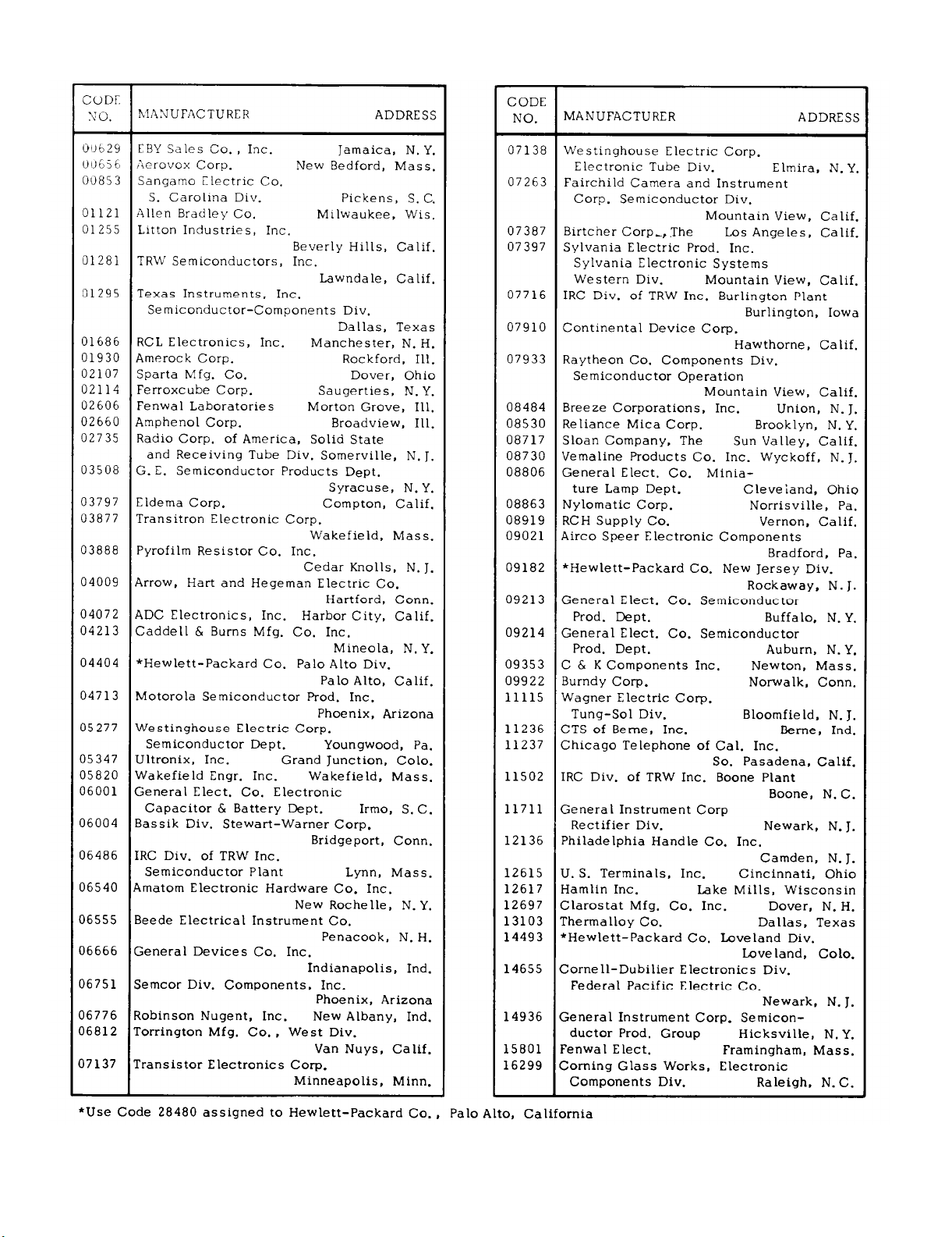
TM 11-6625-2965-14&P
Table 6-3. Code List of Manufacturers
6-2
Page 40
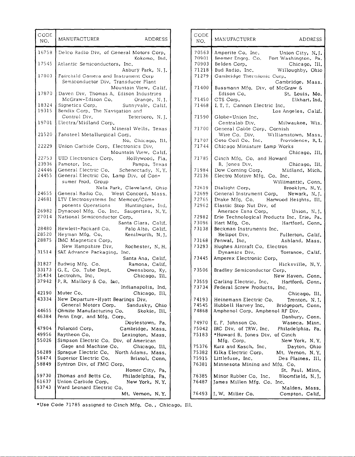
Table 6-3.
Code List of Manufacturers (Continued)
TM 11-6625-2965-l4&P
6-3
Page 41
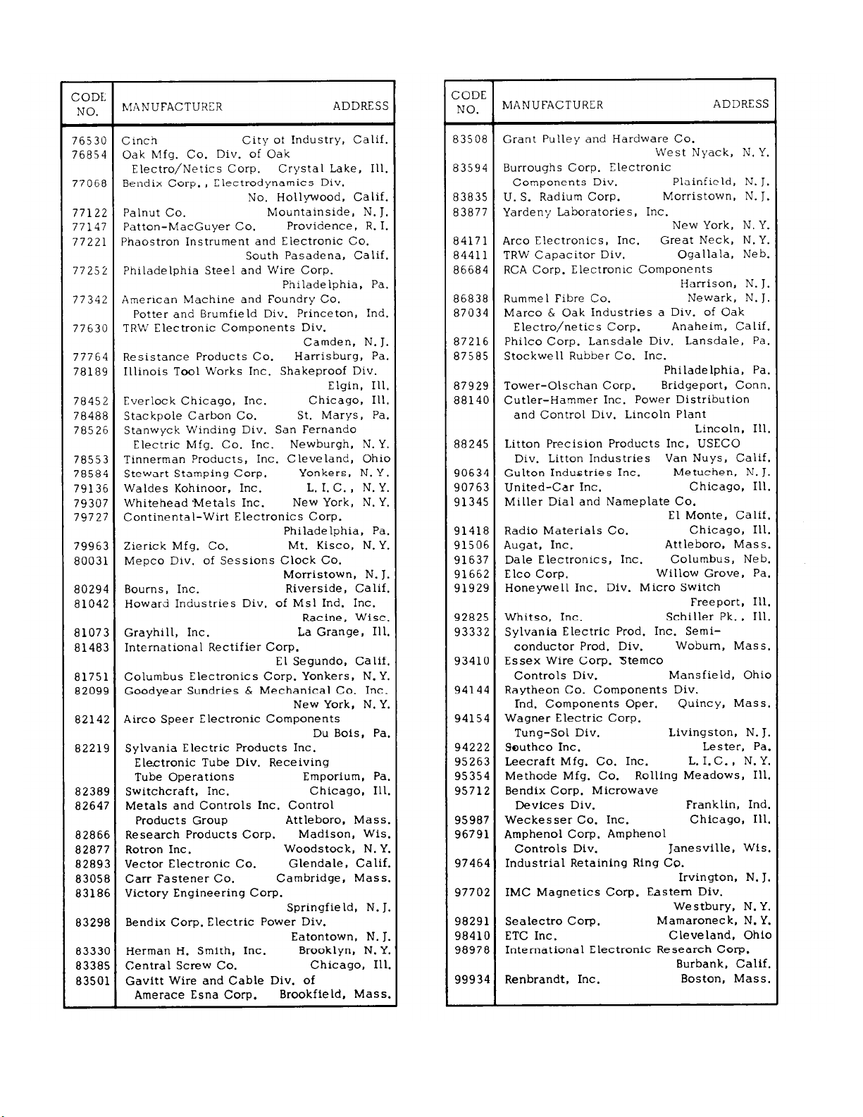
TM 11-6625-2965-14&P
Table 6-3.
Code List of Manufacturers (Continued)
6-4
Page 42

TABLE 6-4. REPLACEABLE PARTS TM11-6625-2965-14&P
REF. MFR. hp
DESIG. DESCRIPTION TQ MFR. PART NO. CODE PART NO. RS
C1 FXD, ELECT 5µ 65VDC 2 09182 0180-1836 1
C2-4,6-8,
11,13,15,
17-19 NOT ASSIGNED - - - - -
C5 FXD, FILM . 001µ 200VDC 2 192P10292 56289 0160-0153 1
C9 FXD, ELECT 4.7ΩF 35VDC 2 150D475X9035B2 56289 0180-0100 1
C10,12 FXD, ELECT 100µUF 50 VDC 4 09182 0180-1852 1
C14 FXD, ELECT 490µF 85 VDC 2 09182 0180-1888 1
C16 FXD, CERAMIC .05µF 400VDC 2 33C17A 56289 0150-0052 1
C20 FXD, ELECT 80µF 300VDC 2 09182 0180-1851 1
CR1,2 RECT. SI. 250MA 200PRV 8 1N485B 93332 1901-0033 6
CR3-5,9,
10,12-15,
18,19,21,
30-33 NOT ASSEIGNED - - - - -
CR6 RECT. SI. 400MW 10PRV 2 1N4828 03508 1901-0461 2
CR7,8 RECY. SI. 400MW 10PRV 4 1N4830 03508 1901-0460 4
CR11 RECY. SI. 500MA 200 PRV 22 1N3253 02735 1901-0389 9
CR16 RECT. SI. 250MA 200PRV 1N485B 93332 1901-0033
CR17 RECT. SI. 500MA 200PRV 1N3253 02735 1901-0389
CR20 RECT. SI. 250MA 200PRV 1N485B 93332 1901-0033
CR22-29,34 RECT. SI. 500MA 200PRV 1N3253 02735 1901-0389
DS1 LAMP NEON 1 09182 2140-0244 1
F1 FUSE CARTRIDGE 2A 250V 3AG 1 312002 75915 2110-0002 5
Q1 SS NPN DIFF. AMP 2 09182 1854-0229 2
Q2,5,6 NOT ASSIGNED - - - - -
Q3 SS PNP SI. 4 09182 1853-0099 4
Q4 SS PNP SI. 2 09182 1853-0041 2
Q7 POWER, NPN SI. 2 09182 1854-0225 2
Q8 SS PNP SI. 09182 1853-0099
Q9,10 SS NPN SI. 4 09182 1854-0071 4
R1 FXD, WW 1KW ±5% 3W 2 242E1025 56289 0813-0001 1
R2 FXD, MET. FILM 6.2KW µ1% 1/8W 2 TYPE CEA T-O 07716 0698-5087 1
R3,4 FXD, MET. FILM 23KW µ1% 1/8W 4 TYPE CEA T-O 07716 0698-3269 1
R5 FXD, MET. FILM 1.5KW ±1% 1/8W 2 TYPE CEA T-O 07716 0757-0427 1
R6 FXD, COMP 360KW ±5% ½W 2 EB-3645 01121 0686-3645 1
R7,9,11
14-28,
32,35-40,
48,50,59
62-71,
74-79,
82-86 NOT ASSIGNED - - - - -
R8 FXD, COMP 560KW ±5% 1/2W 2 EB-5645 01121 0686-5645
R10 VAR. WW DUAL 10K-100 2 09182 2100-0997 1
R12 FXD, WW 1.3KW ±5% 3W 2 242E1325 56289 0811-1803 1
R13 FXD, COMP (SELECTED) ±5% 1/2W 2 TYPE EB (OBD) 01121 1
R29 FXD, COMP 5.1KW ±5% 1/2W 4 EB-5125 01121 0686-5125 1
R30 VAR. WW 5KW (MODIFY) 2 TYPE 110-F4 11236 2100-1824 1
R31 FXD, COMP NKW ±5% 1/2W 2 EB-1025 01121 0686-1025 1
R33 FXD, COMP 2.4KW ±5% 1/2W 2 EB-2425 01121 0686-2425 1
6-5
Page 43

TM11-6625-2965-14&P
REF. MFR. hp
DESIG. DESCRIPTION TQ MFR. PART NO. CODE PART NO. RS
R34 FXD, COMP 300Ω ±5% 1/2W 2 EB-3015 01121 0686-3015 1
R41 RXD, COMP 12KΩ ±5% 1/2W 2 EB-1235 01121 0686-1235 1
R42 FXD, COMP 6.8KΩ ±5% 1/2W 2 EB-6825 01121 0686-6825 1
R43 FXD, MET, FILM 470Ω ±1% 1/4W 2 TYPE CEB T-O 07716 0698-3506 1
R44 FXD, COMP 47KΩ ±5% 1/2W 2 EB-4735 01121 0686-4735 1
R45 FXD, COMP 5.1KΩ ±5% 1/2W EB-5125 01121 0686-5125
R46 FXD, COMP 100KΩ ±5% 1/2W 2 EB-1045 01121 0686-1045 1
R47 FXD, COMP 680Ω ±5% 1/2W 2 EB-6815 01121 0686-6815 1
R49 FXD, MET. OX 3KΩ ±5% 2W 2 TYPE C42S 16299 0698-3642 1
R51 FXD, COMP 20KΩ ±5% 1/2W 2 EB-2035 01121 0686-2035 1
R52 FXD, MET. FILM 1.21KΩ ±1% 1/8W 2 TYPE CEA T-O 07716 0757-0274 1
R53 FXD, COMP 470Ω ±5% 1/2W 2 EB-4715 01121 0686-4715 1
R54,55 FXD, WW 5Ω ±0.5% 1/2W 4 TYPE E-30 01686 0811-1920 1
R56 FXD, MET. FILM 1.69KΩ ±1% 1/8W 2 TYPE CEA T-O 07716 0698-4428 1
R57 FXD, MET. FILM 3.57KΩ ±1% 1/8W 2 TYPE CEA T-O 07716 0698-3496 1
R58 FXD, MET. FILM 196Ω ±1% 1/8W 2 TYPE CEA T-O 07716 0698-3440 1
R60 FXD, MET. FILM 4.81KΩ ±1% 1/4W 2 TYPE CEB T-O 07716 0698-5147 1
R61 FXD, MET. FILM 45KΩ ±1% 1/8W 2 TYPE CEA T-O 07716 0698-5091 1
R72 VAR. WW 250Ω (MODIFY) 2 TYPE 110-F4 11236 2100-0439 1
R73 FXD, MET. FILM 42.2Ω _1% 1/8W 2 TYPE CEA T-O 07716 0757-0316 1
R80 FXD, COMP 33KΩ ±5% 1/2W 1 EB-3335 01121 0686-3335 1
R81 VAR. WW 1K
Ω
2 TYPE 110-F4 11236 2100-0391 1
R87 THERMISTOR 64Ω ±10% 2 LB16J1 02606 0837-0023 1
S1 SWITCH, PILOT LIGHT (RED)
PUSH ON/OFF SPDT 1 54-61681-26 A1H 87034 3101-0100 1
S2 ROTARY SWITCH CONCENTRIC SHAFTS 2 09182 3100-1913 1
T1 TRANSFORMER, POWER 1 09182 9100-1821 1
VR1 DIODE, ZENER 6.2V 2 1N821 06486 1902-0761 2
VR2 DIODE, ZENER 6-19V ±5% 400MW 2 1N753 04713 1902-0049 2
MISCELLANEOUS
COVER, TOP 2 09182 5000-6061
CHASSIS, RIGHT 1 09182 5060-6118
CHASSIS, LEFT 1 09182 5060-6119
PANEL, FRONT 1 09182 06205-00001
BINDING POST (MAROON) 2 09182 1510-0040 1
BINDING POST(BLACK) 4 DF21BC 58474 1510-0039 1
KNOB, BLACK (WITH POINTER) 2 09182 0370-0107 1
KNOB, RED 2 09182 0370-0101 1
KNOB, BAR, RED )WITH POINTER) 2 09182 0370-0102 1
KNOB, BLACK 2 09182 0370-0179 1
METER 2 1/2" DUAL SCALE 0-50V 0-.75A 2 09182 1120-1230 1
BEZEL, METER 1/6 MOD 2 09182 4040-0295 1
SPRING, METER 8 09182 1460-0720 2
GUARD, BARRIER STRIP 1 09182 5020-5541
CABLE CLAMP 1 T4-4 79307 1400-0330
STRAIN RELIEF BUSHING 1 SR-5P-1 28520 0400-0013 1
LINE CORD PLUG PH151 7 1/2' 1 KH-4096 70903 8120-0050 1
JUMPER, BARRIER STRIP 10 422-13-11 013 71785 0360-1143 2
PLASTIC EXTRUDSION BARRIER STRIP 1 09182 4040-0067
BARRIER BLOCK 1 09182 0360-1273 1
FUSEHOLDER 1 342014 75915 1400-0084 1
6-6
Page 44

TM11-6625-2965-14&P
REF. MFR. hp
DESIG. DESCRIPTION TQ MFR. PART NO. CODE PART NO. RS
BRACKET, TRANSF. MFG 2 09182 06205-00002
BRACKET, HEAT SINK 2 09182 5000-6060
HEAT SINK, REAR 1 09182 0050-1035
RUBBER BUMPER (FEET) 4 MB50 87575 0403-0088 1
PRINTED CIRCUIT BOARD 1 09182 06205-20020
RUBBER BUMPER, PRINTED CIRCUIT
BOARD 3 4072 87575 0403-0086 1
HEAT DISSIPATOR (Q7, Q4) 2 NF-207 05820 1205-0033 2
MICA INSULATOR (Q7, Q4) 2 734 08530 0340-0174 2
INSULATOR, TRANSISTOR PINS (Q7, Q40 4 09182 0340-0166 4
INSULATOR (Q7,Q4) 4 09182 0340-0168 4
END CAPS 2 09182 9220-1218
CARTON 1 09182 9211-0848
OPTION 07
10-TURN OUTPUT VOLTAGE CONTROL
R10 VAR. WW 10KΩ ±5% (10 TURN) 2 09182 2100-1866
KNOB 2 09182 0370-0137
OPTION 13
10-TURN VOLTAGE CONTROL
WITH DECADIAL
R10 VAR. WW 10KΩ ±5% (10 TURN) 2 09182 2100-1866
DECADIAL 2 RD-411 07716 1140-0020
6-7
Page 45

TM11-6625-2965-14&P
PART NUMBER - NATIONAL STOCK NUMBER
CROSS REFERENCE INDEX
NATIONAL NATIONAL
PART STOCK PART STOCK
NUMBER FSCM NUMBER NUMBER FSCM NUMBER
DF21BC 58474 5940-00-738-6269 150D475X9035B2 56289 5910-00-177-4300
0150-0052 28480 5910-00-797-4909 150D475X9035B2 56289 5910-00-752-4172
0160-0153 28480 5910-00-965-9728 1510-0039 28480 5940-00-738-6269
0180-0100 28480 5910-00-752-4172 1853-0041 28480 5961-00-931-8259
0180-1836 28480 5910-00-974-6135 1853-0099 28480 5961-00-450-4689
0180-1852 28480 5910-00-931-7060 1854-0071 28480 5961-00-137-4608
0180-1888 28480 5910-00-884-1194 1854-0087 28480 5961-00-824-7567
0370-0101 28480 5355-00-068-4557 1854-0225 28480 5961-00-072-0094
0370-0102 28480 5355-00-906-8933 1854-0229 28480 5961-00-867-9318
0370-0107 28480 5355-00-926-5508 1901-0033 28480 5961-00-821-0710
0686-1045 28480 5905-00-195-6761 1901-0460 28480 5961-00-867-9206
0686-2035 28480 5905-00-903-6304 1901-0461 28480 5961-00-937-3918
0686-3335 28480 5905-00-997-5436 1902-0049 28480 5961-00-911-9277
0686-4735 28480 5905-00-222-5571 1902-3002 28480 5961-00-252-1307
0686-5125 28480 5905-00-279-2019 192P10292 56289 5910-00-993-8305
0698-3440 28480 5905-00-828-0377 2N3417 03508 5961-00-937-3768
0698-3496 28480 5905-00-407-0106 2100-0281 28480 5905-00-918-7471
0698-3506 28480 5905-00-431-6844 2100-0439 28480 5905-00-851-3924
0698-5087 28480 5905-00-469-2837 2100-1824 28480 5905-00-892-9626
0757-0274 28480 5905-00-858-9105 2100-1866 28480 5905-00-110-0282
0757-0316 28480 5905-00-981-7475 2140-0244 28480 5240-00-951-3376
0757-0346 28480 5905-00-998-1906 242E1025 56289 5905-00-504-4892
0757-0427 28480 5905-00-917-0578 30D105G050BA2 56289 5910-00-691-1255
0757-0440 28480 5905-00-858-6795 30D105G050BA2 56289 5910-00-130-2712
0813-0001 28480 5905-00-932-0413 3101-0100 28480 5930-00-918-4381
1N4830 03508 5961-00-103-3950 3101-1248 28480 5930-00-476-9679
1140-0020 28480 5355-00-584-0840 312002 75915 5920-00-280-5062
1205-0033 28480 5999-00-871-9538 342014 75915 5920-00-881-4636
1400-0084 28480 5920-00-881-4636 734 08530 5970-00-840-5109
8120-0050 28480 5625-00-052-4921
6-8
Page 46

SECTION VII
CIRCUIT DIAGRAMS
TM 11-6625-2965-14&P
This section contains the circuit diagrams neces-
sary for the operation and maintenance of this
power supply. Included are:
a.
Component Location Diagram, Figure
7-1, which shows the physical location and refer- identified by encircled numbers on the schematic
ence designator of parts mounted on the printed and printed wiring board.
wiring board.
b.
Schematic Diagram, Figure 7-2, which
illustrates the circuitry for the entire power supply. Voltages are given adjacent to test points,
7-1
Page 47

APPENDIX A
REFERENCES
TM ll-6625-2965-14&P
DA Pam 310-4
DA Pam 310-7
TM 38-750
TM 750-244-2
TM 11-2019
TM 11-6625-203-12
TM 11-6625-654-14
TM 11-6625-822-12
Index of Technical Manuals, Technical Bulletins,
Supply Manuals (Types 7, 8, and 9), Supply
Bulletins,
and Lubrication Orders.
US Army Equipment Index of Modification Work
Orders.
The Army Maintenance Management System
(TAMMS).
Procedures for Destruction of Electronics Materiel
to Prevent Enemy Use (Electronics Command).
Test Sets 1-49, 1-49-A, and 1-49-B and Resistance
Bridges
Operatorfsand
meter
ME-77/u and
operators, Organizational, Direct Support, and
ZM-4A/U
and
ZM-4B/U.
Organizational Maintenance:
AN/uRM-105
AND AN/URW105C (Including
ME-77C/[T).
Multi-
Multimeter,
General Support Maintenance Repair Parts and
Special Tools List (Including Depot Maintenance
Repair Parts and Special Tools List) for
Multimeter AN/USM-223.
Operator and Organizational Maintenance Manual;
Signal Generator
SG-321B/U.
TM 11-6625-2616-14
TM 11-6625-2658-14
TM 11-6625-2724-12
TB 43-180
Operator’s Organizational, Direct Support, and
General Support Maintenance Manual; Digital
Voltmeter
AN/GSM-64A.
Operator’s, Organizational, Direct Support, and
General Support Maintenance Manual for Oscilloscope
AN/uSM-281C
(NSN 6625-OO-1O6-9622).
Operator’s and Organizational Maintenance Manual:
Voltmeter, Electronic
ME-202C/U
(NSN 6625-00-972-4046),
Calibration Requirements for the Maintenance of
Army Materiel.
A-1
Page 48

ICOEIL
TM 11-6625-2965-14&P
APPENDIX B
COMPONENTS OF END ITEM LISTING
1 each Power Supply HP 6205B
BILL
Technical Manual TM 11-6625-2965-14&P
AAL
N/A
N/A
6625-00-437-4861
B-1
Page 49

APPENDIX C
MAINTENANCE ALLOCATION
TM 11-6625-2965-14&P
Section 1.
INTRODUCTION
C -1. General
This appendix provides a summary of the main-
tenance operations for the PP-7548/U. It
authorizes categories of maintenance for specific
maintenance functions on repairable items and
components and the tools and equipment required
to perform each function. This appendix may
be used as an aid in planning maintenance operations.
C-2. Maintenance Function
Maintenance functions will be limited to and defined as follows:
a. Inspect.
item by comparing its physical, mechanical, and/
or electrical characteristics with established standards through examination.
b. Test. To verify serviceability and to detect
incipient failure by measuring the mechanical or
electrical characteristics of an item and comparing those characteristics with prescribed standards.
c. Service. Operations required periodically to
keep an item in proper operating conditions, i.e.,
to clean (decontaminate), to preserve, to drain,
to paint, or to replenish fuel, lubricants, hydraulic
fluids, or compressed air supplies.
d. Adjust
by bringing into proper or exact position, or by
setting the operating characteristics to the specified parameters.
e.
Align.
of an item to bring about optimum or desired
performance.
f. Calibrate. To determine and cause corrections
to be made or to be adjusted on instruments or
test measuring and diagnostic equipments used
To determine the serviceability of an
To maintain, within prescribed limits,
To adjust specified variable elements
in precision measurement. Consists of compari-
sons of two instruments, one of which is a certified
standard of known accuracy, to detect and adjust
any discrepancy in the accuracy of the instrument
being compared.
g.
Install.
ing into position an item, part, module (component or assembly) in a manner to allow the proper
functioning of the equipment or system.
h. Replace.
like type part, subassembly, or module (component
or assembly) for an unserviceable counterpart.
i.
Repair.
ices (inspect, test, service, adjust, align, calibrate,
replace) or other maintenance actions (welding,
grinding, riveting, straightening, facing, rema-
chining, or resurfacing) to restore serviceability
to an item by correcting specific damage, fault,
malfunction, or failure in a part, subassembly,
module (component or assembly), end item, or
system.
j. Overhaul. That maintenance effort (service/
action ) necessary to restore an item to a completely serviceable/operational condition as prescribed
by maintenance standards (i.e., DMWR) in appropriate technical publications. Overhaul is normally
the highest degree of maintenance performed by
the Army. Overhaul does not normally return an
item to like new condition.
k. Rebuild. Consists of those services actions
necessary for the restoration of unserviceable
equipment to a like new condition in accordance
with original manufacturing standards. Rebuild
is the highest degree of materiel maintenance
applied to Army equipment. The rebuild operation
includes the act of returning to zero those age
measurements (hours, miles, etc. ) considered in
classifying Army equipments/components.
The act of emplacing, seating, or fix-
The act of substituting a serviceable
The application of maintenance serv-
C-1
Page 50

TM 11-6625-2965-14&P
C-3. Column Entries
a. Column 1, Group Number. Column 1 lists
group numbers, the purpose of which is to identify
components, assemblies, subassemblies, and mod-
ules with the next higher assembly.
b. Column 2, Component/Assembly. Column 2
contains the noun names of components, assemblies, subassemblies, and modules for which maintenance is authorized.
c. Column 3, Maintenance Functions Column 3
lists the functions to be performed on the item
listed in column 2. When items are listed without
maintenance functions, it is solely for purpose
of having the group numbers in the MAC and
RPSTL coincide.
d. Column 4, Maintenance Category. Column 4
specifies, by the listing of a “worktime” figure in
the appropriate subcolumn (s), the lowest level of
maintenance authorized to perform the function
listed in column 3. This figure represents the ac-
tive time required to perform that maintenance
function at the indicated category of maintenance.
If the number or complexity of the tasks within
the listed maintenance function vary at different
maintenance categories, appropriate “worktime”
figures will be shown for each category. The number of task-hours specified by the “worktime”
figure represents the average time required to
restore an item (assembly, subassembly, component, module, end item or system) to a serviceable
condition under typical field operating conditions.
This time includes preparation time, troubleshooting time, and quality assurance/quality control
time in addition to the time required to perform
the specific tasks identified for the maintenance
functions authorized in the maintenance allocation
chart. SubColumns of column 4 are as follows:
C - Operator/Crew
0- Organizational
F- Direct Support
H - General Support
D - Depot
e. Column 5, Tools and Equipment. Column 6
specifies by code, those common tool sets (not
individual tools) and special tools, test and support equipment required to perform the designated
function.
f. Column 6, Remarks. Column 6 contains an
alphabetic code which leads to the remark in
section IV, Remarks, which is pertinent to the
item opposite the particular code.
C-4. Tool and Test Equipment Requirement
a. Tool or Test Equipment Reference Code. The
numbers
used in the tools and equipment column of the
MAC. The numbers indicate the applicable tool
or test equipment for the maintenance functions.
b. Maintenance Category. The codes in this
column indicate the maintenance category allocated the tool or test equipment.
c. Nomenclature. This column lists the noun
name and nomenclature of the tools and test
equipment required to perform the maintenance
functions.
d. National/NATO Stock Number. This column
lists the National/NATO stock number of the
specified tool or test equipment.
e. Tool Number. This column lists the manu-
facturer’s part number of the tool followed by the
Federal Supply Code for manufacturers (5-digit)
in parentheses.
C-5. Remarks (sect IV)
a. Reference Code. This code refers to the ap-
propriate item in section II, column 6.
b. Remarks. This column provides the required
explanatory information necessary to clarify items
appearing in section II.
(sect Ill)
in this column coincide with the numbers
C-2
Page 51

SECTION II MAINTENANCE ALLOCATION
FOR
POWER SUPPLY PP-7548/U
CHART
(1)
GROUP
NUMBER
00
COMPONENT/ASSEMELY
Power Supply PP-7548/U
o F
0.1
0.1
0.1
(4)
H
0.2
0.2
1.2
0.6
1.3
42
(5)
TOOLS
AND
D
EQPT.
2
1
3
3
3-11
3-11
3
3-11
(6)
REMARKS
A
A
B
c
c
D
D
D
(2)
(3)
MAINTENANCE
FUNCTION
Inspect
Service
Test
Inspect
Service
Test
Adjust
Repair
Overhaul
MAINTENANCE CATEGORY
c
C-3
Page 52

SECTION III TOOL AND TEST EQUIPMENT REQUIREMENTS
FOR
POWER SUPPLY PP-7548/U
TOOL OR TEST
EQUIPMENT MAINTENANCE NOMENCLATURE NATIONAL/NATO TOOL NUMBER
REF CODE CATEGORY STOCK NUMBER
1 0 MULTIMETER AR/URM-105 6625-00-581-2036
2 0 TOOL KIT, ELECTRONIC EQUIPMENT TK-101/G 5180-00-064-5178
3 H, D TOOL KIT, ELECTRONIC EQUIPMENT TK-105/G 5180-00-610-8177
4 H, D GENERATOR, SIGNAL SG-321/U 6625-00-674-7097
5 H, D MULTIMETER AN/USM-223/U 6625-00-999-7465
6 H, D MULTIMETER, ELECTRONIC ME-260()/U 6625-00-965-1534
7 H, D OSCILLOSCOPE AN/USM-281 6625-00-106-9622
8 H, D RESISTANCE BRIDGE ZM-4()/U 6625-00-500-9370
9 H, D TRANSFORMER, VARIABLE CN-16/U 5950-00-235-2086
10 H, D VOLTMETER, DIGITAL AN/GSM()/64 6625-00-022-7894
11 H, D VOLTMETER, ELECTRONIC ME-202()/U 6625-00-709-0288
C-4
Page 53

REFERENCE
CODE
SECTION IV.
REMARKS
POWER SUPPLY PP-7548/U
REMARKS
A
B
c
D
Exterior
Operational
Interior
All
C-5
Page 54

TM 11-6625-2965-14&P
APPENDIX
D
MANUAL BACKDATING CHANGES
Manual backdating changes describe changes necessary to adapt this manual to earlier instruments. TO
adapt the manual to serial numbers prior to 7L2301 inspect the following table for your serial number and
then make the appropriate changes.
CHANGE 1:
In the replaceable parts table, make the following
changes:
Delete Q10.
Delete R51.
Change R53 to fxd, comp 10 ±5% ½W, EB-1005,
01121, part No. 0686-1005.
Change R54 to fxd, ww 5.25 ±0.5% ½W, Type
E-30, 01686, Part No, 0811-1921.
Change R81 to var. ww 100 , Type 110-F4,
11236, Part No. 2100-0281.
On the schematic remove transistor Q10 in current
limit circuit and connect circuit as shown in
Figure B-1.
The circuit description Paragraph 4-19 should now
read as follows:
4-19 Current limiting occurs when diode CR16
becomes forward biased.
is
determined by the voltage at the base of Q4.
The cathode potential of CR16 is determined by
the voltage drop acress resistors R53 and R81
Its anode potential
For serial numbers 7L4450 and up check for inclusion of change sheet.
Figure B-1.
which, in turn, are connected across the current sampling resistor(s). The cathode potential of CR16 is a function of the output current.
A
S this current increases, the drop across the
sampling network increases, and CR16 will
start to conduct.
clamps the base of Q4 to a potential which decreases the conduction of the series regulator,
thus limiting the output current,
R81 permits the cathode potential of CR16 to be
varied and thus charges the current limiting
threshold.
Paragraph 5-52, Step (e) should read:
“Adjust R81 until differential voltmeter indicates
2.55 Vdc . . . .”
Conduction of this diode
Potentiometer
D-1
Page 55

TM 11-6625-2965-14&P
Option 11, Overvoltage Protection “Crowbar”
DESCRIPTION:
This option is installed in DC Power Supplies, 6200B, 6201B, 6202B, 6203B, 6204B, and 6206B, and
tested at the factory. It consists of a printed circuit board,
and six wires that are soldered to the main power supply board.
The crowbar monitors the output voltage of the power supply and fires an SCR that effectively shorts
the output when it exceeds the preset trip voltage.
CROWBAR ADJUST control on the front panel.
The trip voltage is determined by the setting of the
The trip voltage range is as follows:
screwdriver-type front panel potentiometer,
Model
Trip Voltage Range
To prevent transients from falsely tripping the crowbar, the trip voltage must be set higher than the
power supply output voltage by the following margin: 4% of the output voltage plus 2V. The margin repre-
sents the minimum crowbar trip setting for a given output voItage;
than this margin.
OPERATION:
1. Turn the CROWBAR ADJUST fully clockwise to set the trip voltage to maximum.
2.
Set the power supply VOLTAGE control for the desired crowbar trip voltage. To prevent false crowbar tripping, the trip voltage should exceed the desired output voltage by the following amount: 4% of the
output voltage plus 2V.
3. Slowly turn the CROWBAR ADJUST ccw until the crowbar trips, output goes to 0V or a small posi-
tive voltage.
4. The crowbar will remain activated and the output shorted until the supply is turned off. To reset
the crowbar, turn the supply off, then on.
5. If the CROWBAR must be completely disabled, remove the lead attached to the CROWBAR ADJUST
potentiometer R5.
6200B 6201B
2.5-44V
2.5-23V
6202B 6203B
2.5-44V 2.5-10V 2.5-44V
the trip voltage can always be set higher
6204B
6205B
2.5-44V 2.5-65V
6206B
D-2
Page 56

TM11-6625-2965-14&P
TABLE A-1. REPLACEABLE PARTS
REF. MFR. hp
DESIG. DESCRIPTION TQ MFR. PART NO. CODE PART NO. RS
C1 FXD, ELECT 1µF 50VDC 2 30D105G050BA2 56289 0180-0108 1
C2 FXD, MICA 510µF 500VDC 2 RCM15E511J 04062 0140-0047 1
CR1-CR3 RECT. SI. 200MA 200PRV 6 1N485B 93332 1901-0033 6
CR4 SCR 7.4A 100PRV 2 C20B 03508 1884-0032 2
Q1,2 SS NPN SI. 4 2N3417 03508 1854-0087 4
R1 FXD, MET. FILM 10Ω ±1% 1/8W 2 TYPE CEA T-O 07716 0757-0346 1
R2 FXD, COMP 3KΩ ±5% 2W 2 TYPE C42S 16299 0698-3642 1
R3 FXD, MET. FILM 1.21LΩ ±1% 1/8W 2 TYPE CEA T-O 07716 0757-0274 1
R4 FXD, MET. FILM 7.5KΩ ±1% 1/8W 2 TYPE CEA T-O 07716 0757-0440 1
R5 VAR. WW 10KΩ ±5% 2 09182 2100-1854 1
R6 FXD, WW 1KΩ ±5% 3W 2 242E1025 56289 0813-0001 1
R7 FXD, COMP 22Ω ±5% 1/2W 2 EB-2205 01121 0686-2205 1
R8 FXD, MET. FILM 196Ω ±1% 1/8W 2 TYPE CEA T-O 07716 0698-3440 1
T1 TRANSFORMER, PULSE 1 09182 5080-7122 1
VR1 DIODE, ZENER 6.19V±5% 2 1N753 04713 1902-0049 2
VR2 DIODE, ZENER 2.37V±5% 2 1N4370 04713 1902-3002 2
MISCELLANOEUS
PRINTED CIRCUIT BOARD (BLACK) 1 09182 06205-20021
P.C. BOARD (INCLUDES COMPONENTS) 1 09182 06205-60021
HEAT SINK 1 09182 06205-00003
INSULATOR (CR4) 2 09182 0340-0462 1
MICA WASHER 2 09182 2190-0709 1
D-3
Page 57

TM 11-6625-2965-14&P
D-4
Figure A-1.
*For Model 6205B the above circuit is duplicated on each half of the assembled
board, 06205-60021.
Models 6200B, 6204B, and 6205B* Overvoltage Protection “Crowbar”
Page 58

MANUAL CHANGES
Model 6205B DC Power Supply
Manual HP Part No. 06205-90002
ITM 11-6625-2965-14&P
Make all corrections in the manual according to errata below,
supply serial number and enter any listed change(s) in the manual.
The primary wiring of the unit is now as shown
SERIAL
Prefix Number
ALL
7L
7L
lC
1140A
- 5900 1
5451
5901 - 6200
6201 - 6300
6301 - up 1,2,3,4
MAKE
CHANGE S
Errata
1,2
1,2,3
below.
ERRATA:
On Page 3-1, in Paragraph 3-2, delete step (b)
and reletter following steps appropriately; change
step (c) to read:
operating mode. . . ”;
“Set range switch to desired
change step (d) to read: “Ad-
just coarse and fine voltage controls until. . ."
On Page 5-4, in Paragraph 5-16, change steps (b)
through (d) to read as follows:
The Serial Prefix of this unit has been changed to
1140A. This is the only change.
b. Set METER switch to low current range and
RANGE switch to high voltage mode.
c, Turn on supply and adjust VOLTAGE controls
until front panel meter indicates exactly 300mA
(0.5 ampere for Model 6206B supplies).
d. Differential voltmeter should read 1.5 ±
in the instructions for auto-series operation in
paragraph 3-33, change the third sentence to
read:
0.045Vdc.
CHANGE 1:
In the replaceable parts table, make the following
change:
Terminal Strip: Add, HP Part No. 0360-0401.
CHANGE 2:
In the replaceable parts table, make the following
changes:
S1: Change to
HP Part No. 3101-1248.
In miscellaneous:
Panel, Front: Change to HP Part No. 06205-00004.
On page A-1 under Description, add “6205B” to
the first sentence. Also change the second
sentence of the second paragraph to read, “The
trip voltage is determined by the setting of the
crowbar adjust control on the front panel (except
in the Model 6205B, where it is accessible through
a hole in the top cover). “ Also on page A-1,
change the last part of the third step under Operation to read “. . . output goes to O volts or a
small positive voltage. “
CHANGE 3:
In the replaceable parts table and on the schematic
make the following changes:
Tl: Change to HP Part No. 9100-2611.
On the schematic and in the parts list, change
resistor R12 (for both dual supplies) to 1.4k
5% 3W 30 ppm, HP Part No. 0811-1804.
then check the following table for your power
CHANGE 4:
ERRATA :
“The value of Rx is this voltage divided by the
voltage programming current of the slave sup-
ply (l/Kp,
where K
is the resistance program
p
-
ming coefficient for constant voltage operation). “
The voltage programming current of the Model
6205B is 1/200 ohms per volt, or 5 milliamps.
D-5
Page 59
Manual Changes/Model 6205B
TM 11-6625-2965-14&P
DESCRIPTION
Front Panel, Lettered
STANDARD
06205-00005
HP PART NO.
OPTION A85
06205-60004
OPTION X95
Chassis, Right Side
Chassis, Left Side
Cover, Top
Rack Kit (accessory)
Heatsink
ERRATA:
In parts list, change HP Part No. of rubber bumper
(qty. 4) to 0403-0002.
In Figure 5-4, change Rx value listed for Model
6206B to 3 ohms.
In Table 1-1, change the INTERNAL IMPEDANCE
AS A CONSTANT VOLTAGE SOURCE (Output Impe-
dance) specification to read as follows:
Output Impedance (Typical): Approximated
by a 25 milliohm resistance in series with a 1
micro henry inductance.
The standard colors for this instrument are now
mint gray (for front panel) and olive gray (for
all other external surfaces). Option X95 designates use of the former color scheme of light
gray and blue gray.
of a light gray front panel with olive gray used
for all other external surfaces. New part numbers
shown above.
Option A85 designates use
5060-7956
5060-7955
5000-9424
14523A
06205-60005
5060-6118
5060-6119
5000-6061
14523A-A85
06205-60002
ERRATA:
Effective January 1, 1977, Option 007 (1O-turn
voltage control) has been redesignated Option 009,
and Option 013 (1 O-turn voltage control with deca dial) has been redesignated Option 015. Make
these changes wherever Option 007 or 013 is mentioned in the manual.
The front panel binding posts have been changed to
a type with better designed insulation.
two types of posts listed on page 6-6 of the parts
list and add :
0114 (qty. 4); and red binding post HP Part No.
1510-0115 (qty. 2).
black binding post, HP Part No. 1510-
Delete the
● The corrugated shipping carton for this model has
been changed to HP Part No. 9211-2570. Two
9220-2703 floater pads are used.
The blue-gray meter bezel has been replaced by a
black one, HP Part No. 4040-0414.
In Figure 3-9, delete the six references to TP23.
These wires must be connected in the appropriate
power supply directly to the end of R54 that is
towards the rear of the supply. Another correction
needed in this figure is that the wire from terminal
A6 in Slave No. 1 in the two-unit example at the
top of the figure should be connected to the rear
of R54 in the master supply. Note: The range
switches of the master and slave supplies must
be set to the same range when operating in autoparellel.
Add to the parts list the replacement lamp for
illuminated switch 3101-1248, which is used in
those supplies that include Change 2. The HP
Part No. of the type A1H lamp is 2140-0244.
D-6
8-5-77
Page 60

TM 11-6625-2965-14&P
Figure 7-1. Component Location Diagram
Figure 7-2. Schematic Diagram, Model 6205B
Page 61

Page 62

By Order of the Secretary of the Army:
Official:
J. C. PENNINGTON
Major General, United States Army
The Adjutant General
Distribution:
Active Army:
TSG (l)
USAARENBD (1)
USAINSCOM (2)
TRADOC (2)
DARCOM (1)
TECOM (2)
OS Maj Cmd (2)
USACC (2)
HISA Ft Monmouth (21)
Armies (1)
USASIGS (10)
Svc Colleges (1)
Ft Richardson (CERCOM Oft) (1)
Ft Carson (5)
Ft Gillem (10)
USMR (1)
USA ERDAA(l)
USAERDAW (1)
Army Dep (1) except:
LBAD (10)
SAAD (30)
TOAD (14)
SHAD (3)
USA Dep (1)
Sig Sec USA Dep (1)
Units org under fol TOE:
29-134 (1)
29-136 (1)
29-207 (2)
29-610 (2)
NG: None.
USAR: None.
For explanation of abbreviations used, see AR 310-50.
E. C. MEYER
General, United States Army
Chief
of Staff
Page 63

Page 64
Page 65

Page 66
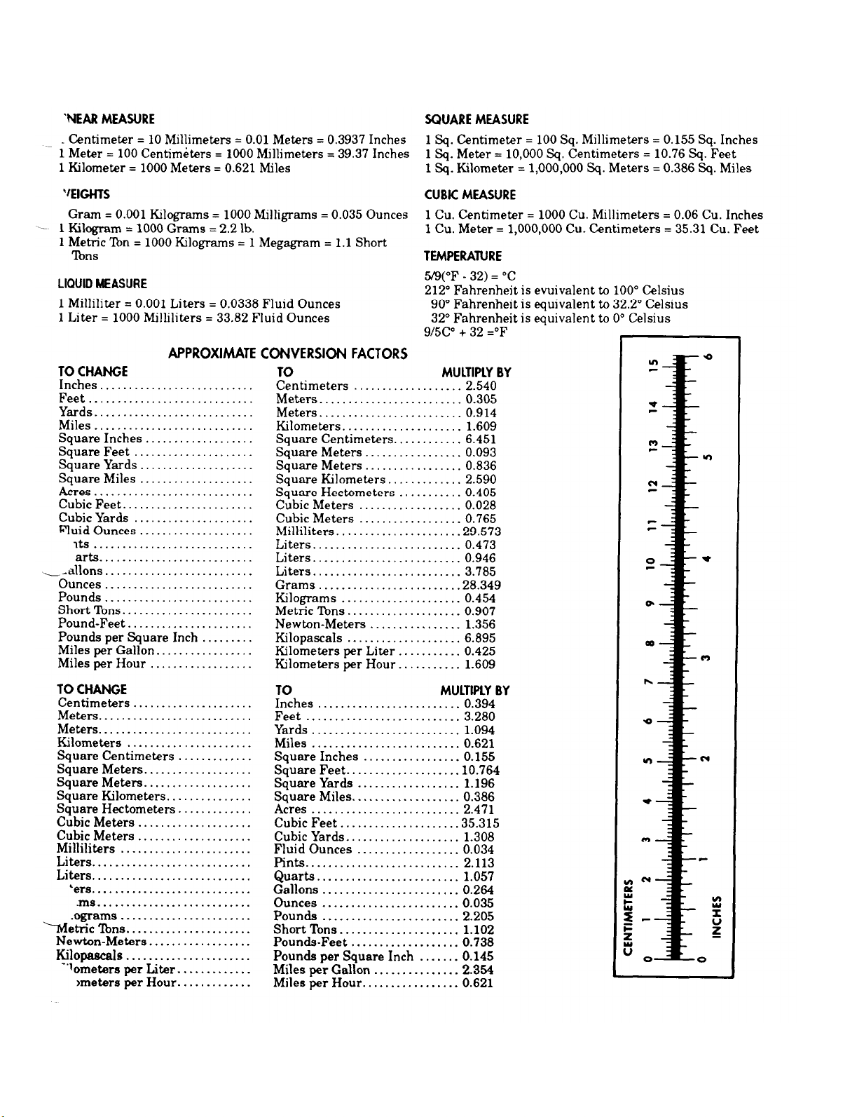
THE METRIC SYSTEM AND EQUIVALENTS
Page 67

PIN: 044061-000
Page 68

 Loading...