

Page 1

HPE 6127XLG Blade Switch Series
IRF
Configuration Guide
Part number: 797703-002
Software version: Release 24xx
Document version: 6W101-20170705
Page 2

© Copyright 2017 Hewlett Packard Enterprise Development LP
The information contained herein is subject to change without notice. The only warranties for Hewlett Packard
Enterprise products and services are set forth in the express warranty statements accompanying such
products and services. Nothing herein should be construed as constituting an additional warranty. Hewlett
Packard Enterprise shall not be liable for technical or editorial errors or omissions contained herein.
Confidential computer software. Valid license from Hewlett Packard Enterprise required for possession, use, or
copying. Consistent with FAR 12.211 and 12.212, Commercial Computer Software, Computer Software
Documentation, and Technical Data for Commercial Items are licensed to the U.S. Government under vendor’s
standard commercial license.
Links to third-party websites take you outside the Hewlett Packard Enterprise website. Hewlett Packard
Enterprise has no control over and is not responsible for information outside the Hewlett Packard Enterprise
website.
Acknowledgments
Intel®, Itanium®, Pentium®, Intel Inside®, and the Intel Inside logo are trademarks of Intel Corporation in the
United States and other countries.
Microsoft® and Windows® are trademarks of the Microsoft group of companies.
Adobe® and Acrobat® are trademarks of Adobe Systems Incorporated.
Java and Oracle are registered trademarks of Oracle and/or its affiliates.
UNIX® is a registered trademark of The Open Group.
Page 3

Contents
Setting up an IRF fabric ·····································································1
Overview ···································································································································· 1
Network topology ·················································································································· 2
Basic concepts ····················································································································· 2
Interface naming conventions ·································································································· 4
File system naming conventions ······························································································· 4
Configuration synchronization ·································································································· 6
Master election ····················································································································· 6
Multi-active handling procedure ································································································ 6
MAD mechanisms ················································································································· 7
Hardware compatibility ················································································································ 12
General restrictions and configuration guidelines ············································································· 12
Software requirements ········································································································· 12
IRF physical interface requirements ························································································ 12
Connecting IRF ports ··········································································································· 13
Feature compatibility and configuration restrictions ···································································· 13
Configuration backup ··········································································································· 14
Setup and configuration task list ··································································································· 14
Planning the IRF fabric setup ······································································································· 15
Assigning a member ID to each IRF member device ········································································· 15
Specifying a priority for each member device ··················································································· 16
Connecting IRF physical interfaces ································································································ 16
Binding physical interfaces to IRF ports ·························································································· 17
Accessing the IRF fabric ·············································································································· 19
Configuring a member device description ······················································································· 19
Configuring IRF link load sharing mode ·························································································· 19
Configuration restrictions and guidelines ·················································································· 19
Configuring the global load sharing mode ················································································ 20
Configuring a port-specific load sharing mode ··········································································· 20
Configuring IRF bridge MAC persistence ························································································ 20
Enabling software auto-update for software image synchronization ····················································· 21
Configuration prerequisites···································································································· 22
Configuration procedure ······································································································· 22
Setting the IRF link down report delay ···························································································· 22
Configuring MAD ······················································································································· 23
Configuring LACP MAD ········································································································ 23
Configuring BFD MAD ·········································································································· 24
Configuring ARP MAD ·········································································································· 25
Configuring ND MAD ··········································································································· 27
Excluding a port from the shutdown action upon detection of multi-active collision ··························· 28
Recovering an IRF fabric ············································································································· 28
Displaying and maintaining an IRF fabric ························································································ 30
Configuration examples ··············································································································· 30
LACP MAD-enabled IRF configuration example (using crosslink ports) ·········································· 30
BFD MAD-enabled IRF configuration example (using crosslink ports) ··········································· 32
ARP MAD-enabled IRF configuration example (using uplink ports) ··············································· 35
ND MAD-enabled IRF configuration example (using uplink ports) ················································· 39
Document conventions and icons ······················································ 44
Conventions ······························································································································ 44
Network topology icons ··············································································································· 45
Support and other resources····························································· 46
Accessing Hewlett Packard Enterprise Support················································································ 46
Accessing updates ····················································································································· 46
Websites ··························································································································· 47
Customer self repair ············································································································ 47
i
Page 4

Remote support ·················································································································· 47
Documentation feedback ······································································································ 47
Index ··························································································· 48
ii
Page 5
NOTE:
IRF member devices in this document are HPE 6127XLG switch modules.
•
•
•
•
•
IP network
IRF fabric
IP network
IRF link
Simplified to
Master
Subordinate
Setting up an IRF fabric
Overview
The Intelligent Resilient Framework (IRF) technology is proprietar y to Hewlett Packard Ent erprise.
The technology virtualizes multiple physical devices at the same layer into one virtual fabric to
provide data center c lass availabi lit y and sc alabilit y. IRF virtualization technol og y offers processing
power, interaction, unified management, and uninterrupted maintenance of multiple devices.
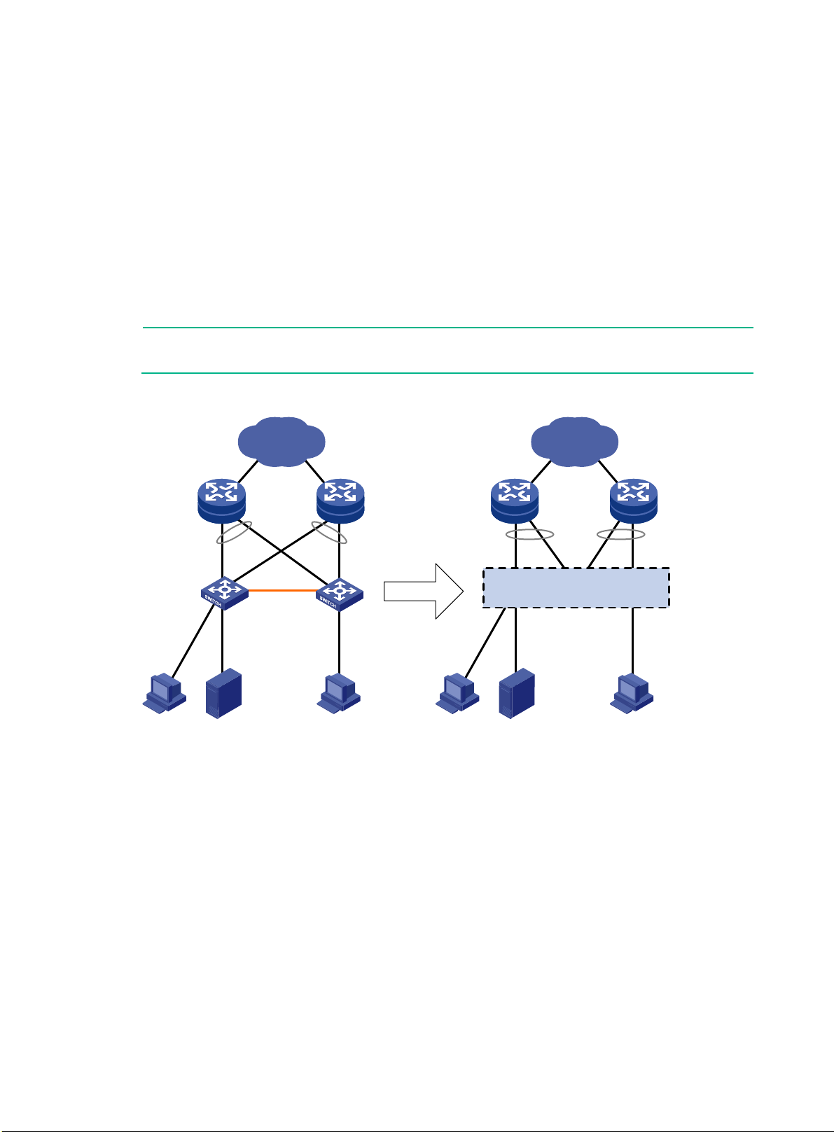
Figure 1 sho ws an IRF fabric that has two member devices, which appear as a single node to th e
upper-layer and lower-layer devices.
Figure 1 IRF application scenario
IRF provides the following benefits:
Simplified topology and easy management—An IRF fabric appears as one node and is
accessible at a single IP address on the network. You can use this IP address to log in at any
member device to manage all the members of the IRF fabric. In addition, you do not need to run
the spanning tree feature among the IRF members.
1:N redundancy—In an IRF fabric, one member acts as the master to manage and control the
entire IRF fabric. All the other members process services while backing up the master. When
the master fails, all the other member devices elect a new master from among them to take over
without interrupting services.
IRF link aggregation—You can assign several physical links between neighboring members
to their IRF ports to create a load-balanced aggr e gat e IR F connection with redundancy.
Multi-member link aggregation—You can use the Ethernet link aggregation feature to
aggregate the physical links between the IRF fabric and its upstream or downstream devices
Network scalability and resiliency—Processing capacity of an IRF fabric equals the total
across the IRF members.
processing capacities of all the members. You can increase ports, network bandwidth, and
1
Page 6

processing capacity of an IRF fabric simply by adding member devices without changing the
network topology.
Network topology
An IRF fabric can use a daisy-chain or ring topology . IRF does not support the full mesh topology. For
information about connecting IRF member devices, see "Connecting IRF physical interfaces."
Basic concepts
IRF member roles
IRF uses two member roles: master and standby (called subordinate throughout the
documentation).
When devices form an IR F f abr ic, they elect a master to manage and control the I RF f abr ic, and all
the other devices back up the master. When the master device fails, the other devices automatically
elect a new master. For more information about master election, see "Master election."
IRF member ID
An IRF fabric uses member IDs to uniquely ident ify and manage its members. This member ID
information is included as the first part of interface numbers and file paths to uniquely identify
interfaces and files i n a n IR F f abric . For more information about inter f ac e and f i le path naming, see
"Interface naming conventions" and "File system naming conventions."
If two devices have the same IRF member ID, they cannot form an IRF fabric. If the IRF member ID
of a device has been used in an IRF fabric, the device cannot join the fabric.
IRF port
An IRF port is a logic al interface that con nects IRF mem ber devices. Eve ry IRF-capabl e device
supports two IRF port s. The IRF ports are nam ed IRF-port n/1 and IRF-port n/2, where n is the
member ID of the device. The two IRF ports are referred to as IRF-port 1 and IRF-port 2 in this boo k.
To use an IRF port, you must bind a minimum of one physical interface to it. The phys i cal interfaces
assigned to an IRF port automatically form an aggregate IRF l ink . An IRF port goes down only if all
its IRF physical interfaces are down.
IRF physical interface
IRF physical interfaces connect IRF member devices and must be bound to an IRF port. They
forward the IRF pr otocol packets between IRF member devices and the data packets that must
travel across IRF member devices.
For more inform ation about physical interfaces that c an be used for IRF links, see "IRF physical
interface requirements."
MAD
An IRF link failure causes an IRF fabric to split in two IRF fabrics operat ing with the s ame La yer 3
settings, including the sam e IP address. To avoid IP address collision and net work problems, IRF
uses multi-active detection (MAD) mechanisms to detect the presence of multiple identical IRF
fabrics, handle collisions, and recover from faults.
IRF domain ID
One IRF fabric forms one IRF domain. IRF uses IRF domain IDs to uniquely identify IRF fabrics and
prevent IRF fabrics from interfering with one another.
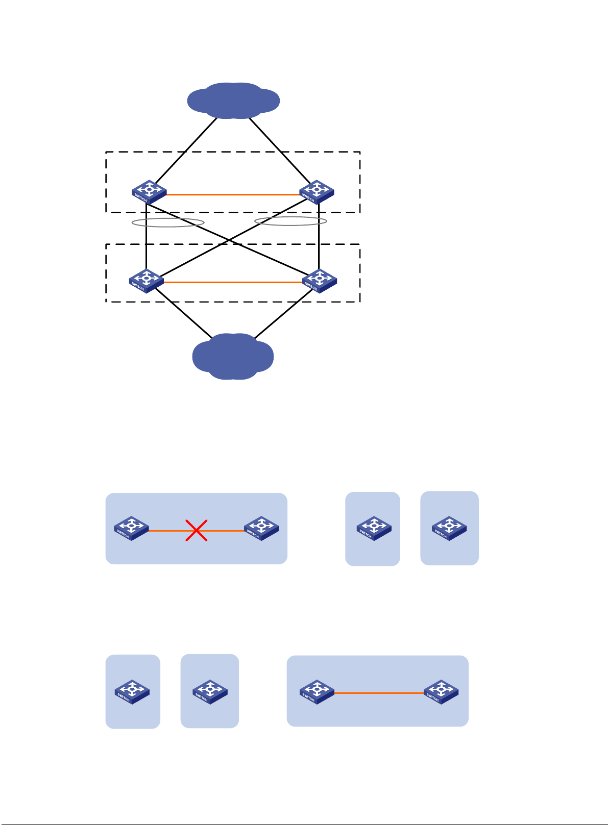
As shown in Figure 2, IRF fabric 1 contains Device A and Device B, and IRF fabric 2 contains Device
C and Device D. Both fabrics use the LACP aggregate links between them for MAD. When a
member device receives an extended LACPDU for MAD, it checks the domain ID to see whether the
packet is from the local IRF fabric. Then, the device can handle the packet correctly.
2
Page 7
Device A
Device B
IRF fabric 1
(domain 10)
IRF link
Core network
IRF fabric 2
(domain 20)
IRF link
Device C
Device D
Access network
=
IRF link
Device A Device B
IRF fabric
Device A
Device B
IRF fabric 1
IRF fabric 2
+
IRF link
Device A Device B
Device A
Device B
IRF fabric 1
IRF fabric 2
IRF fabric
+
=
Figure 2 A network that contains two IRF domains
IRF split
IRF split occurs when an I RF f abric breaks up into multiple IRF fabric s bec a us e of IR F link failures,
as shown in Figure 3 . The split IRF fabrics operate with the same IP address. IRF spl it causes
routing and forwarding problems on the network. To quickly detect a multi-active collision, configure
a minimum of one MAD mechanism (see "Configuring MAD").
Figure 3 IRF split
IRF merge
IRF merge occurs when two split IRF fabrics reunite or when two independent IRF fabrics are united,
as shown in Figure 4.
Figure 4 IRF merge
3
Page 8
•
•
•
•
•
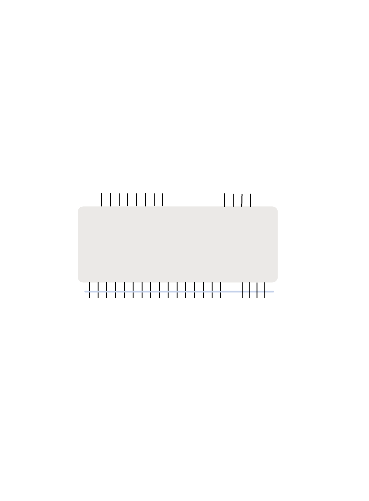
6127XLG
External uplink port
1
23
4
5
6
7
8
9
1011
12
SFP+ port
QSFP+ port
Internal downlink port
Backplane
1 2 3 4 5 6 7 8
9
101112 13 14
15
16
17 18
1920
Internal crosslink port
Member priority
Member priority determines the possibility of a m em ber de vice t o b e e lec te d th e m as ter. A member
with higher priority is more likely to be elected the master.
Interface nami ng conventions
Physical interfaces include uplink ports, downlink ports, and crosslink ports.
A physical interface is named in the slot-number/subslot-number/port-index format.
slot-number—IRF member ID of the switch module. This argument defaults to 1. The IRF
member ID always takes effect, whether or not the module has formed an IRF fabric with other
switch modules. If the module is alone, the module is considered to be a single-member IRF
fabric.
subslot-number—The subslot number of the uplink ports on the front panel is fix ed at 1. The
subslot number of the downlink ports and crosslink ports on the rear panel is fixed at 0.
port-index—Port index of the interface. To identify the port index, see Figure 5.
Figure 5 Port indexes
For example:
On the single-member IRF fabric Sysname, FortyGigE 1/1/1 represents the first uplink port on
On the multi-member IRF fabric Master, FortyGigE 3/1/1 represents the first uplink port on the
File system naming c onventions
On a single-member fabric, you can use its storage device name to access its file system.
the front panel. Set its link type to trunk, as follows:
<Sysname> system-view
[Sysname] in terface fortygige 1/1/1
[Sysname-FortyGigE1/1/1] port link-type trunk
front panel of member device 3. Set its link type to trunk, as follows:
<Master> system-view
[Master] interf ace fortygige 3/1/1
[Master-FortyGigE3/1/1] port link-type trunk
4
Page 9

On a multi-member IRF fabric, you can use the storage device name to access the file system of the
master. To access the file system of any other member device, use the name in the
slotmember-ID#storage-device-name format.
For example:
To access the test folder under the root directory of the flash memory on the master device:
<Master> mkdir te st
Creating direct ory flash:/test. .. Done.
<Master> dir
Directory of flas h:
0 -rw- 43548660 Jan 01 2011 08:21:29 system.ipe
1 drw- - Jan 01 2011 00:00:30 diagfile
2 -rw- 567 Jan 02 2011 01:41:54 dsake y
3 -rw- 735 Jan 02 2011 01:42:03 hostk ey
4 -rw- 36 Jan 01 2011 00:07:52 ifindex.dat
5 -rw- 0 Jan 01 2011 00:53:09 lauth .dat
6 drw- - Jan 01 2011 06:33:55 license
7 drw- - Jan 02 2000 00:00:07 logfile
8 -rw- 23724032 Jan 01 2011 00:49:47 switch-cmw710-system.bin
9 drw- - Jan 01 2000 00:00:07 seclog
10 -rw- 591 Jan 02 2011 01:42:03 serverkey
11 -rw- 4609 Jan 01 2011 00:07:53 startup.cfg
12 -rw- 3626 Jan 01 2011 01:51:56 startup.cfg_bak
13 -rw- 78 833 Jan 01 2011 00:07: 53 startup.mdb
14 drw- - Jan 01 2011 00:15:48 test
25 drw- - Jan 01 2011 04:16:53 versionI nfo
524288 KB total (365292 KB free)
T o create and access the test folder under the root directory of the flash memory on member device
3:
<Master> mkdir sl ot3#flash:/tes t
Creating direct ory slot3#flash: /test... Done.
<Master> cd slot3#flash:/test
<Master> pwd
slot3#flash:/test
Or:
<Master> cd slot3#flash:/
<Master> mkdir te st
Creating direct ory slot3#flash: /test... Done.
T o copy the file test.ipe on the master to the root directory of the flash memory on member device 3:
# Display the c urr ent wor king path. In this exam ple, th e c ur rent working path is the root d irec tory of
the flash on member device 3.
<Master> pwd
slot3#flash:
# Change the current working path to the root directory of the flash memory on the master device.
<Master> cd flash:/
<Master> pwd
flash:
5
Page 10

•
•
•
•
NOTE:
Master election does not occur when two split IRF fabrics merge.
# Copy the file to member device 3.
<Master> copy tes t.ipe slot3#flas h:/
Copy flash:/test.ipe to slot3#f lash:/test.ipe?[Y/N]:y
Copying file flas h:/test.ipe to slo t3#flash:/tes t.ipe... Done.
For more inform ation about storage de vice naming conve ntions, see Funda mentals Configurat ion
Guide.
Configuration synchronization
IRF uses a strict running-configuration synchron ization mechanism. In a n IRF fabric, all member
devices get and run the running configuration of the master. Any configuration change is
automatically propagated from the master to the oth er member devices. The configur ation files of
these devices are still ret a ined, b ut th e s e files do not take effect. The devices use their o wn s tartup
configuration files only after they are removed from the IRF fabric.
For more information about configuration management, see Fundamentals Configuration Guide.
Master election
Master election occurs each time the IRF fabric topology changes in the following situations:
The IRF fabric is established.
The master device fails or is removed.
The IRF fabric splits.
Independent IRF fabrics merge.
Master election selects a master in descending order:
1. Current master, even if a new member has higher priority. When an IRF fabric is being formed, all members consider themselves as the master. This rule
is skipped.
2. Member with higher priority. If all members have the same priority, this rule is skipped.
3. Member with the longest system uptime.
Two members are considered to start up at the same time if the difference between their startup
times is equal to or less than 10 minutes. For these members, the next tiebreaker applies.
4. Member with the lowest CPU MAC address.
For the setup of a ne w IRF fabr ic, the su bordinat e dev ices m us t reboot to complete the setup af ter
the master election.
For an IRF merge, devices must reboot if they are in the IRF fabric that fails the master election.
Multi-active handling procedure
The multi-active handling procedure includes detection, collision handling, and failure recovery.
Detection
MAD identifies eac h IRF fabric with a dom ain ID and an active ID (th e member ID of the m as ter ). If
multiple active IDs are detected in a domain, MAD determines that an IRF coll ision or split has
occurred.
6
Page 11

•
•
IMPORTANT:
You can configure BFD MAD, ARP MAD, and ND MAD together in an IRF fabric for prompt IRF split
detection
they handle collisions differently.
For more information about the MAD mechanisms and their application scenarios, see "MAD
mechanisms."
Collision handling
When MAD detects a m ulti -ac tive c o llis ion, it sets all IRF fabrics except one to th e Recovery state.
The fabric that is not placed in Rec overy state can contin ue to forward traffic . The Recover y-state
IRF fabrics are inactive and cannot forward traffic.
LACP MAD uses the following process to handle a multi-active collision:
1. Compares the number of members in each fabric.
2. Sets all fabrics to the Recovery state except the one that has the most members.
3. Compares the member IDs of the masters if all IRF fabrics have the same number of members.
4. Sets all fabrics to the Recovery state except the one that has the lowest numbered master.
5. Shuts down all physica l network ports in the Recovery-state fabrics except for the following
ports:
IRF physical interfaces.
Ports you have specified wi th the mad exclude interface command.
In contrast, BFD MAD, ARP MAD, and ND MAD do not compare the number of members in fabrics.
These MAD mechanisms use the following process to hand a multi-active collision:
1. Compare the member IDs of the masters in the IRF fabrics.
2. Set all fabrics to the Recovery state except the one that has the lowest numbered master.
3. Take the same action on the network ports in Recovery-state fabrics as LACP MAD.
Failure recovery
To merge two split IRF fabrics, first repair the failed IRF link and remove the IRF link failure.
If the IRF fabric in Recovery state fails before the failure is recovered, repair the failed IRF fabric
and the failed IRF link.
If the active IRF fabric fails before the failure is recovered, enable the inactive IRF fabric to take
over the active IRF fabric. Then, recover the MAD failure.
MAD mechanisms
IRF provides MAD mechanisms by extending LACP, BFD, ARP, and IPv6 ND.
Table 1 compares the MAD mechanisms and their application scenarios.
Table 1 Comparison of MAD mechanisms
MAD
mechanism
. However, do not configure any of these mechanisms together with LACP MAD, because
Advantages Disadvantages Application scenario
Link aggregation is used
between the IRF fabric and
its upstream or downstream
device.
For information about LACP,
see Layer 2—LAN Switching
Configuration Guide.
LACP MAD
• Detection speed is
fast.
• Does not require
MAD-dedicated
physical links or
Layer 3 interfaces.
Requires an intermediate device
that supports extended LA CP for
MAD.
7
Page 12

•
•
•
•
•
MAD
mechanism
BFD MAD
ARP MAD
ND MAD
Advantages Disadvantages Application scenario
• No special
requirements for
network scenarios.
• If no intermediate
device is used, this
mechanism is only
suitable for IRF fabrics
that have a small
number of members
that are geographically
close to one another.
For information about BFD,
see High Availability
Configuration Guide.
Spanning tree-enabled
non-link aggregation IPv4
network scenario.
For information about ARP,
see Layer 3—IP Services
Configuration Guide.
Spanning tree-enabled
non-link aggregation IPv6
network scenario.
• Detection speed is
fast.
• No intermediate
device is required.
• Intermediate
device, if used,
can come from any
vendor.
• No intermediate
device is required.
• Intermediate
device, if used,
can come from any
vendor.
• Does not require
MAD dedicated
ports.
• No intermediate
device is required.
• Intermediate
device, if used,
can come from any
vendor.
• Does not require
MAD dedicated
ports.
• Requires MAD dedicated
physical links and Layer 3
interfaces, which cannot be
used for transmitting user
traffic.
• If no intermediate device is
used, any two IRF
members must have a BFD
MAD link to each other.
• If an intermediate device is
used, every IRF member
must have a BFD MAD link
to the intermediate device.
• Detection speed is slower
than BFD MAD and LACP
MAD.
• The spanning tree feature
must be enabled.
• Detection speed is slower
than BFD MAD and LACP
MAD.
• The spanning tree feature
must be enabled.
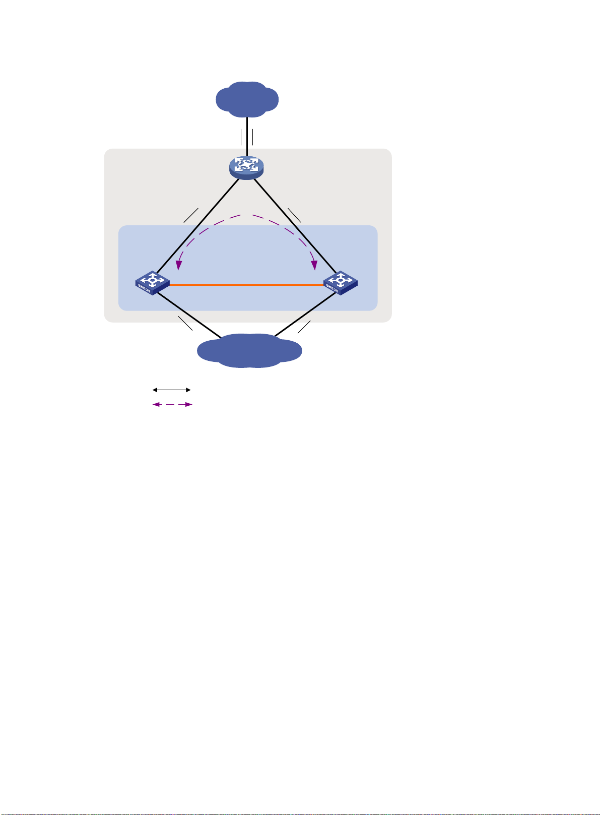
LACP M AD
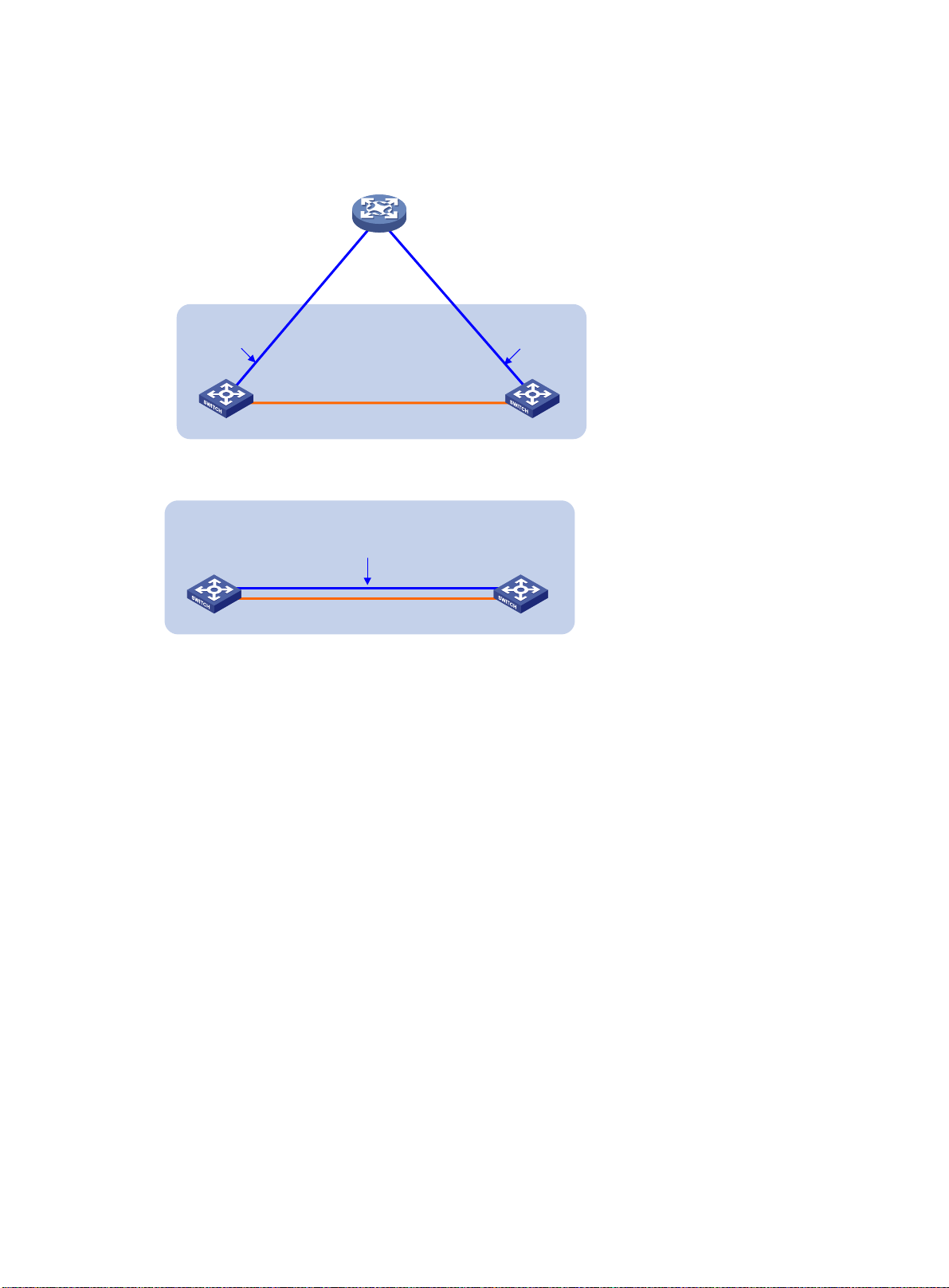
As shown in Figure 6, LACP MAD has the following requirements:
Every IRF member must have a link with an intermediate device.
All the links form a dynamic link aggregation group.
The intermediate device must be a device that supports extended LACP for MAD.
The IRF member devices send extended LACPDUs that convey a domain ID and an active ID. The
intermediate device transparently forwards the extended LACPDUs received from one member
device to all the other member devices.
If the domain IDs and active IDs sent by all the member devices are the same, the IRF fabric is
If the extended LACPDUs convey the same domain ID but different active IDs, a split has
integrated.
occurred. LACP MAD handles this situation as described in "
8
Collision handling."
Page 13

•
•
•
NOTE:
The MAD addresses identify the member devices and must
As a best practice, use an intermediate device to connect IRF member devices if the IRF fabric
has more than two member devices. A full mesh of IRF members might cause broadcast loops.
•
Intermediate device
Master
Subordinate
IRF fabric
Internet
Customer
premise
network
IRF link
Common traffic path
LACP MAD traffic path
LACP-enabled dynamic
link aggregation
LACP-enabled dynamic
link aggregation
Figure 6 LACP MAD scenario
BFD MAD
BFD MAD can work with or without intermediate devices. Figure 7 shows a typical BFD MAD
scenario that uses an intermediate device. Figure 8 shows a typical BFD MAD scenario that does not
use an intermediate device.
To use BFD MAD:
Set up dedicated BFD MAD link between each pair of IRF members or between each IRF
member and the intermediate device. Do not use the BFD MAD links for any other purposes.
Assign the ports connected by BFD MAD links to the same VLAN.
On the intermediate device (if any), you must also create the VLAN and assign the ports on the
BFD MAD links to the VLAN.
Create a VLAN interface for the VLAN, and assign a MAD IP address to each member on the
VLAN interface.
With BFD MAD, the master attempts to establish BFD sessions with other member devices by using
its MAD IP address as the source IP address.
If the IRF fabric is integrated, only the MAD IP address of the master takes effect. The master
belong to the same subnet.
cannot establish a BFD session with an y other mem ber. If you execute the display bfd
session command, the state of the BFD sessions is Down.
9
Page 14
•
•
•
•
•
Device
Master
Subordinate
IRF fabric
IRF link
192.168.1.2/24
192.168.1.3/24
BFD MAD linkBFD MAD link
Master
Subordinate
IRF fabric
IRF link
BFD MAD link
VLAN 2
192.168.1.2/24
VLAN 2
192.168.1.3/24
When the IRF fabric splits, the IP addresses of the masters in the split IRF fabrics take effect.
The masters can establish a BFD session. If you execute the display bfd session command,
the state of the BFD session between the two devices is Up.
Figure 7 BFD MAD scenario with intermediate device
Figure 8 BFD MAD scenario without intermediate device
ARP MAD
ARP MAD detects multi-active collisions by using extended ARP packets that convey the IRF
domain ID and the acti ve ID.
ARP MAD can work with or without an interm ediate device. Mak e sure the following requirem ents
are met:
Figure 9 shows a typical ARP MAD scenario that uses an intermediate device.
Each IRF member compares the dom ain ID and the ac tive ID in incom ing extended ARP pack ets
with its domain ID and active ID.
If an intermediate device is used, connect each IRF member device to the intermediate device.
Run the spanning tree feature between the IRF fabric and the intermediate device. In this
situation, data links can be used.
If an intermediate device is not used, connect each IRF member device to all other member
devices. In this situation, IRF links cannot be used for ARP MAD.
If the domain IDs are different, the extended ARP packet is from a different IRF fabric. The
device does not continue to process the packet with the MAD mechanism.
If the domain IDs are the same, the device compares the active IDs.
If the active IDs are different, the IRF fabric has split.
If the active IDs are the same, the IRF fabric is integrated.
10
Page 15
•
•
Device
Master
Subordinate
IRF
fabric
Internet
Customer
premise
network
IRF link
Common traffic path
Extended ARP traffic path
STP domain (all devices
must run the spanning
tree feature)
Figure 9 ARP MAD scenario
ND MAD
ND MAD detects multi-ac tive col lisions by using NS packets to transm it the IRF domain ID and the
active ID.
Y ou can set up ND MAD links between neighbor IRF member devices, or between each IRF member
device and an intermediate device (see Figure 10). If an intermediate device is used, you must also
run the spanning tree protocol between the IRF fabric and the intermediate device.
Each IRF member device compares the domain ID and the active ID in incoming NS packets with its
domain ID and active ID.
If the domain IDs are different, the NS packet is from a different IRF fabric. The device does not
continue to process the packet with the MAD mechanism.
If the domain IDs are the same, the device compares the active IDs.
If the active IDs are different, the IRF fabric has split.
If the active IDs are the same, the IRF fabric is integrated.
11
Page 16

Device
Master
Subordinate
IRF
fabric
Internet
Customer
premise
network
IRF link
Common traffic path
Extended ND traffic path
STP domain (all devices
must run the spanning
tree feature)
Figure 10 ND MAD scenario
Hardware compatibility
An HPE 6127XLG switch module can form an IRF fabric only with switch modules in the sam e
series.
General restrictions and configuration guidelines
For a successful IRF setup, follow the restrictions and guidelines in this section and the setup
procedure in "Setup and configuration task list."
Software requir ements
All IRF member devices must run the same software image version. Make sure the software
auto-update feature is enabled on all member devices.
IRF physical interface requirements
Candidate IRF physical interfaces
T o connect switch modules in different chassis into an IRF fabric, you must use the SFP+ or QSFP+
uplink ports on the front panel.
To connect switch modules in the same chassis into an IRF fabric, use the following ports:
12
Page 17

•
•
•
•
•
NOTE:
The modules and
are subject to change over time. For the most
up
sales representative.
If the switch modules have internal crosslinks, use the crosslink ports on the rear panel as a
best practice. These ports are invisible to users and do not require physical cabling.
The HP 6127XLG or HP 6127XLG TAA switch module has four crosslink ports, which are
numbered 17, 18, 19, and 20. By default, the four ports are shut down to avoid loops.
The crosslink ports used as IRF physical interfaces on neighboring members must have the
same interface number.
If the switch modules do not have internal crosslinks, you must use the SFP+ or QSFP+ uplink
ports on the front panel.
To identify internal cross links between switch modules in a chassis, see t he enclosure setup a nd
installation guide.
Selecting transceiver modules and cables
When you select transceiver modules and cables, follow these restrictions and guidelines:
Use SFP+ or QSFP+ DAC cables to connect SFP+ or QSFP+ ports in a short distance.
Use SFP+ or QSFP+ transceiver modules and fibers to connect SFP+ or QSFP+ p orts in a long
distance.
The transceiver modules at the two ends of an IRF link must be the same type.
For more information about the SFP+ and QSF P+ transc eiver modules, see t he switch installat ion
guide and HPE Comware-Based Dev ices Transceiver Modules User Guide.
DAC cables available for IRF links
-to-date list of modules and DAC cables for IRF links, contact your Hewlett Packard Enterprise
Connecting IRF ports
When you connect two ne ighbor ing IR F m ember s, connect th e ph ysical interfaces of IRF-port 1 o n
one member to the physical interfaces of IRF-port 2 on the other.
Feature compatibility and configuration restrictions
Make sure the feature settings in Table 2 are the same across member devices.
Table 2 IRF and feature compatibility
Feature Command Remarks
Enhanced ECMP mode
Maximum number of ECMP
routes
Table capacity mode
Support for the IPv6 routes
with prefixes longer than 64
bits
ecmp mode enhanced
max-ecmp-num
switch-mode
switch-routing-mode
ipv6-128
See Fundamentals Configuration Guide.
See Layer 3—IP Routing Configuration
Guide.
See Layer 3—IP Routing Configuration
Guide.
See Layer 3—IP Routing Configuration
Guide.
System operating mode
system-working-mode
13
See Fundamentals Configuration Guide.
Page 18

Configuration backup
As a best practice, back up the next-startup configuration file on a device before adding the device to
an IRF fabric as a subordinate device.
A subordinate device's next-startup configuration file might be overwritten if the master and the
subordinate use the same file name for their next-startup configuration files. Y ou can use the backup
file to restore the original configuration after removing the subordinate from the IRF fabric.
Setup and configuration task list
To set up an IRF fabric, perform the following tasks:
Tasks at a glance Remarks
1. (Required.) Planning the IRF fabric setup
2. (Required.) Assigning a member ID to each IRF member device
3. (Optional.) Specifying a priority for each member device
4. (Required.) Connecting IRF physical interfaces
5. (Required.) Binding physical interfaces to IRF ports
6. (Required.) Accessing the IRF fabric
7. (Optional.) Configuring a member device description
8. (Optional.) Configuring IRF link load sharing mode:
Configuring the global loa d sh ar ing mode
Configuring a port-specific load sharing mod e
N/A
Perform this task on each
member device.
Perform this task on one or
multiple member devices to affect
the master election result.
For information about connecting
the crosslink ports, see the user
manual for the enclosure.
Perform this task on each
member device.
When you complete IRF port
binding and activation on all IRF
member devices, the IRF fabric is
formed.
When you log in to the IRF fabric,
you are placed at the master's
CLI, where you complete
subsequent IRF settings and
configure other features for the
member devices as if they were
one device.
N/A
N/A
9. (Optional.) Configuring IRF bridge MAC persistence
10. (Optional.) Enabling software auto-update for software image
synchronization
11. (Optional.) Setting the IRF link down report delay
12. (Required.) Configuring MAD:
Configuring LACP MAD
Configuring BFD MAD
14
N/A
As a best practice, enable
software auto-update to ensure
system software image
synchronization.
N/A
MAD mechanisms are
independent of one another. You
can configure multiple MAD
mechanisms for an IRF fabric.
Page 19

Configuring ARP MAD
•
•
•
•
•
•
CAUTION:
In an IRF fabric, changing IRF member I
even data loss. Before you do that, back up the configuration and make sure you fully understand
the impact on your network. For example, all member
in an IRF fabric are the same model.
If you swapped the IDs of any two members, their interface settings would also be swapped.
settings can continue to take
Tasks at a glance Remarks
Configuring ND MAD
Excluding a port from the shutdown action upon detection of
multi-active collision
13. (Optional.) Recovering an IRF fabric
N/A
Planning the IRF fabric setup
Consider the following items when you plan an IRF fabric:
Hardware compatibility and restrictions.
IRF fabric size.
Master device.
IRF physical interfaces.
Member ID and priority assignment scheme.
Fabric topology and cabling scheme.
For more information about hardware and cabling, see the switch installation guide.
Assigning a member ID to each IRF member device
Ds might cause undesirable configuration changes and
devices
To create an IRF fabric, you must assign a unique IRF member ID to each member device.
To prevent any undesirable configuration change or data loss, avoid changing member IDs after the
IRF fabric is formed.
The new member ID takes effect at a reboot. After th e device reb oots, the s ettings on al l member
ID-related physical resources (including common physical network ports) are removed, regardless of
whether you have saved the configuration.
To assign a member ID to a device:
Step Command Remarks
1. Enter system view.
2. Assign a member ID to a
member device.
3. (Optional.) Save the
configuration.
system-view
irf member
new-member-id
save
member-id
N/A
renumber
The default IRF member ID is 1.
If you have bound physical
interfaces to IRF ports or
assigned member priority, save
the configuration before
rebooting the device so these
15
Page 20

effect after the reboot.
system-view
•
•
IMPORTANT:
No intermediate devices are allowed between neighboring members.
IRF-port 1IRF-port 2
IRF fabric
Step Command Remarks
4. Reboot the device.
reboot [ slot
slot-number ] [
force ]
N/A
Specifying a priority for each member device
IRF member priority represents the possibility for a device to be elected the master in an IRF fabric.
The higher the priority, the higher the possibility.
A change to member priority affects the election result at the next master election. However, it does
not cause an immediate master re-election.
To specify a priority for a member device:
Step Command Remarks
1. Enter system view.
2. Specify a priority for the
device.
irf member
priority
member-id
priority
N/A
The default IRF member pr ior it y
is 1.
Connecting IRF physical interfaces
When you connect two nei ghboring IRF m em bers, c onnect the ph ysic al in ter f aces of IR F-port 1 on
one member to the physical interfaces of IRF-port 2 on the other.
For example, you have four member devices: A, B, C, and D. IRF-port 1 and IRF-port 2 are
represented by A1 and A2 on mem ber device A, represented by B1 and B2 on mem ber device B,
and so on. To connect the four mem ber devices into a ring topolo gy of A-B-C-D(A), the IRF link
cabling scheme must be one of the following:
A1-B2, B1-C2, C1-D2, and D1-A2.
A2-B1, B2-C1, C2-D1, and D2-A1.
Figure 11 shows how to connect two switch modules.
Figure 11 Connecting IRF physical interfaces
Figure 12 shows how to connect two switch modules through crosslink ports numbered 17.
16
Page 21

•
•
6127XLG
Inter-switch
Crosslink
17
6127XLG
17
1
2
IRF-port2 IRF-port1
IRF fabric
Ring topology
Subordinate
Subordinate
Master
IRF-port 1 IRF-port 2
IRF-port 1
IRF-port 2IRF-port 1
IRF-port 2
Daisy-chain topology
IRF
fabric
Master
Subordinate
Subordinate
IRF-port 2
IRF-port 2
IRF-port 1
IRF-port 1
Figure 12 Connecting IRF member devices by using crosslink ports
You can connect the devices into a daisy-chain topology or a ring topology. A ring topology is more
reliable (see Figure 13). In ring topology, the failure of one IRF link does not cause the IRF fabric to
split as in daisy-chain topology. Rather, the IRF fabric changes to a daisy-chain topology without
interrupting network services.
Figure 13 Daisy-chain topology vs. ring topology
Binding physical interfaces to IRF ports
When you bind physical interf ac es to IRF ports, follow these guidelines:
Follow the restrictions in "IRF physical interface requirements."
Y ou must alway s shut dow n a physical interface before binding it to an IRF port or removing the
binding. Start the shutdown operation on the master, and then the member device that has the
fewest number of hops from the master.
On a physical int er f ac e bound to an IRF port, you can ex ecute only the following commands:
Command category Commands Remarks
Basic Ethernet interface
commands
LLDP commands
• description
• flow-interval
• shutdown
• lldp admin-status
• lldp check-change-interval
• lldp enable
• lldp encapsulation snap
• lldp notification
• lldp tlv-enable
remote-change enable
17
See Layer 2—LAN Switching
Configuration Guide.
See Layer 2—LAN Switching
Configuration Guide.
Page 22

quit
To bind physical inter faces to IRF ports:
Step Command Remarks
1. Enter system view.
2. Enter interface view or
interface range view.
3. Shut down the interface or
the range of interfaces.
4. Return to system view.
5. Enter IRF port view.
6. Bind each physical
interface to the IRF port.
7. Return to system view.
8. Enter interface view or
interface range view.
9. Bring up the interface or
the range of interfaces.
10. Return to system view.
system-view
• Enter interface range view:
interface range { interface-type
interface-number [ to
interface-type
interface-number ] } &<1-24>
• Enter interface view:
interface interface-type
interface-number
shutdown
quit
irf-port
port group interface
interface-number
member-id/port-number
interface-type
quit
• Enter interface range view:
interface range { interface-type
interface-number [ to
interface-type
interface-number ] } &<1-24>
• Enter interface view:
interface interface-type
interface-number
undo shutdown
N/A
To shut down a range of IRF
physical interfaces, enter
interface range view.
To shut down one IRF physical
interface, enter its interface view.
By default, all interfaces are up.
N/A
N/A
By default, no physical inter faces
are bound to any IRF port.
Repeat this step to assign
multiple physical interfaces to
the IRF port for link redundancy.
You can bind up to four physical
interfaces to an IRF port.
N/A
N/A
N/A
N/A
11. Save the configuration.
12. Activate the IRF port
settings.
save
irf-port-configuration active
18
Activating IRF port settings
causes IRF merge and reboot.
To avoid data loss, save the
running configuration to the
startup configuration file before
you perform the operation.
After this step is performed, the
state of the IRF port changes to
UP, the member devices elect a
master automatically, and the
subordinate device reboots
automatically.
After the IRF fabric is formed,
you can add additional physical
interfaces to an IRF port (in UP
state) without repeating this step.
Page 23

•
•
•
•
•
•
Accessing the IRF fabric
The IRF fabric appears as one device after it is formed. Y ou configure and manage all IRF members
at the CLI of the master. All settings you have made are automatically propagated to the IRF
members.
The following methods are available for accessing an IRF fabric:
Local login—Log in through the console port of any member device.
Remote login—Log in at a Layer 3 interface on any member device by using methods
including Telnet and SNMP.
When you log in to an IRF fabric, you are placed at the CLI of the mas ter, regardless of at which
member device you are logged in.
For more information, see login configuration in Fundamentals Configuration Guide.
Configuring a member device description
Step Command Remarks
1. Enter system view.
2. Configure a description for
a member device.
system-view
irf member
text
member-id
description
N/A
By default, no member device
description is configured.
Configuring IRF link load sharing mode
An IRF port distributes traffic across its physical links.
By default, traffic is distr ibuted automatically based on packet types, includin g Layer 2, IPv4, and
IPv6. You can configure the IRF port to distri bute traffic based on criteri a including IP addresses ,
MAC addresses, and the combination of IP and MA C addresses. If the device does not sup port a
criterion combination, the system displays an error message.
Configure the IRF link load sharing mode for IRF links in system view or IRF port view:
In system view, the configuration is global and takes effect on all IRF ports.
In IRF port view, the configuration is port specific and takes effect only on the specified IRF port.
An IRF port preferent iall y uses the port -specific load s haring mode. If no port-specific load sharing
mode is available, the IRF port uses the global load sharing mode.
The IRF link load sharing mode takes effect on all types of packets, including unicast, multicast, and
broadcast.
Configuration restrictions and guidelines
To distribute traffic based on TCP/UDP ports, use one of the following methods:
Use the default setting for both global and port-specific IRF link load sharing modes.
Set the IRF link load sharing mode and the global load sharing mode for Ethernet link
aggregation as follows:
Set the IRF link load sharing mode to distribute traffic based on source IP, destination IP, or
both source and destination IP addresses. The command syntax is irf-port load-sharing
mode { destination-ip | source-ip } *.
19
Page 24

•
Set the global load sharing mode for Ethernet link aggregation to distribute traffic based on
source service port, destination service port, or both source and destination service ports.
The command syntax is link-aggregation global load-sharing mode { destination-port |
source-port } *. For more information about Ethernet link aggregation load sharing, see
Layer 2—LAN Switching Configuration Guide.
Configuring the global load sharing mode
Step Command Remarks
1. Enter system view.
2. Configure the global IRF
link load sharing mode.
system-view
irf-port global load-sharing mode
destination-ip
{
source-ip | source-mac
destination-mac
|
} *
N/A
By default, packets are
distributed automatically across
IRF member links based on
packet types.
|
If you execute this command
multiple times, the most recent
configuration takes effect.
Configuring a port-specific load sharing mode
Before you configure a port -specific load sharing m ode, make sure you have bound a m ini mum of
one physical interfac e to the IRF port.
To configure a port-specific load sharing mode for an IRF port:
Step Command Remarks
1. Enter system view.
2. Enter IRF port view.
3. Configure the port-specific
load sharing mode.
system-view
irf-port
irf-port load-sharing mode
{
source-ip | source-mac
member-id/port-number
destination-ip
|
destination-mac
} *
N/A
N/A
By default, the global IRF link
load sharing mode applies.
|
If you execute this command
multiple times, the most recent
configuration takes effect.
Configuring IRF bridge MAC persistence
By default, an IRF fabric us es the bridge MAC address of the master device as its br idge MAC
address. Layer 2 protocols, such as LACP, use this bridge MAC address to identify the IRF fabric. On
a switched LAN, the brid ge MAC address must be unique.
To avoid duplicate bridge MAC addresses, an IRF fabric can change its bridge MAC address
automatically after its bridge MAC owner leaves. However, the change causes temporary traffic
disruption.
Depending on the network condition, enable the IRF fabric to retain or change its bridge MAC
address after the address owner leaves. Available options include:
irf mac-address persistent timer—Bridge MAC address of the IRF fabric remains unchanged
for 6 minutes after the address owner leaves. If the owner does not return before the timer
expires, the IRF fabric uses the bridge MAC address of the current master as its bridge MAC
address. This option avoids unnecessary bridge MAC address changes caused by device
reboot, transient link failure, or purposeful link disconnection.
20
Page 25

•
NOTE:
IRF fabrics that
bridge MAC owner
same as
address of the old IRF fabric.
•
•
•
IMPORTANT:
T
rebooting
auto
to configuration
terminals (see Netw ork Manage me nt and Mon itor ing C onf igura tio n Gu ide).
irf mac-address persistent always—Bridge MAC address of the IRF fabric does not change
after the address owner leaves.
have the same bridge MAC address cannot merge. If you use the removed
as the master device in a new fabric, the bridge MAC of the new fabric is the
the old fabric. For the two IRF fabrics to merge, you must change the bridge MAC
undo irf mac-address persistent—Bridge MAC address of the current master replaces the
original one as soon as the owner of the original bridge MAC leaves.
When you configure IRF bridge MAC persistence, follow these guidelines:
If ARP MAD or ND MAD is used, configure the undo irf mac-address persistent command to
enable immediate bridge MAC address change after the address owner leaves.
Configure the irf mac-address persistent always command in the following situations:
TRILL is configured. The persistence setting ensures that other devices in the TRILL
network can maintain correct network topology after the address owner leaves.
The IRF fabric uses a daisy-chain topology, and it has aggregate links with upstream or
downstream devices. The persistence setting prevents transmission delay or packet loss
after the address owner leaves.
To configure the IRF bridge MAC persistence setting:
Step Command Remarks
1. Enter system view.
2. Configure IRF bridge MAC
persistence.
system-view
• Retain the bridge MAC address
permanently even if the owner
has left the IRF fabric:
irf mac-address persistent
always
• Retain the bridge MAC address
for 6 minutes after the owner
leaves the fabric:
irf mac-address persistent
timer
• Change the bridge MAC
address as soon as the owner
leaves the fabric:
undo irf mac-address
persistent
N/A
By default, the IRF bridge MAC
address remains unchanged for
6 minutes after the address
owner leaves the fabric.
Enabling software auto-update for software image synchronization
o ensure a successful software auto-update in a multi-user environment, prevent anyone from
-update status, configure the information center to output the status messages
The software auto-update feature synchronizes the current software images of the master in an IRF
fabric to all its members automatically.
member devices during the auto-update process. To inform administrators of the
21
Page 26

•
•
•
•
To join an IRF fabric, a device must use the same software images as the master in the fabric.
When you add a device to the IRF fabric, software auto-update compares the startup software
images of the device with the c urrent sof tware im ages of the IR F mas ter. If the two sets of images
are different, the device automatically performs the following operations:
1. Downloads the current software images of the master.
2. Sets the downloaded images as main startup software images.
3. Reboots with the new software images to rejoin the IRF fabric.
You must manually update the new device with the software images running on the IRF fabric in the
following situations:
Software auto-update is disabled.
Software auto-update fails to update software. This situation might occur if the IRF fabric
cannot identify the software version used on the new device.
Configuration p rerequisites
Make sure the dev ice you are adding to the IRF fabric has sufficient storage space for the new
software images.
If sufficient storage space is not available, the device automatically de letes the current software
images. If the rec la imed space is still i ns ufficient, the d ev ic e ca nnot complete the auto-update. You
must reboot the device, and then access the Boot menus to delete files.
Configuration procedure
To enable software image synchronization:
Step Command Remarks
1. Enter system view.
2. Enable software
auto-update.
system-view
irf auto-update enable
N/A
By default, software
auto-update is enabled.
Setting the IRF link down report delay
To prevent f requent IRF splits and merges during link flapping, configure the IRF ports to delay
reporting link down events.
An IRF port does not report a link down event to the IRF fabric immediately after its link changes from
up to down. If the IRF link state is still down when the delay is reached, the port reports the change to
the IRF fabric.
IRF ports do not dela y link up events. The y report the link up e vent immediatel y after the IRF link
comes up.
When you configure the IRF link down report delay, follow these restrictions and guidelines:
Make sure the IRF link down report delay is shorter than the heartbeat or hello timeout settings
of upper-layer protocols (for example, CFD, VRRP, FCoE, and OSPF). If the report delay is
longer than the timeout setting of a protocol, unnecessary recalculations might occur.
Set the delay to 0 seconds in the following situations:
The IRF fabric requires a fast master/subordinate or IRF link switchover.
The BFD or GR feature is used.
22
Page 27

•
•
•
•
•
•
•
•
interface route-aggregation
You want to shut down an IRF ph ysical interface or reboot an IRF member device. (After
you complete the operation, reconfigure the delay depending on the network condition.)
To set the IRF link down report delay:
Step Command Remarks
1. Enter system view.
2. Set the IRF link down
report delay.
system-view
irf link-delay
Configuring MAD
When you configure MAD, follow these restrictions and guidelines:
You can configure BFD MAD, ARP MAD, and ND MAD together in an IRF fabric for prompt IRF
split detection. However, do not configure any of these mechanisms together with LACP MAD,
because they handle collisions differently.
If LACP MAD, ARP MAD, or ND MAD runs between two IRF fabrics, assign each fabric a
unique IRF domain ID. (For BFD MAD, this task is optional.)
An IRF fabric has only one IRF domain ID. You can change the IRF domain ID by using the
following commands: irf domain, mad en able, mad arp enable, or mad nd enable. The IRF
domain IDs configured by using these commands overwrite each other.
To prevent a port from being shut down when the IRF fabric transits to the Recovery state, use
the mad exclude interface command. To bring up ports in a Recovery-state IRF fabric, use the
mad restore command instead of the undo shutdown command. The mad restore command
activates the Recovery-state IRF fabric.
Configuring LACP MAD
interval
N/A
The default IRF link down report delay is 4
seconds.
When you use LACP MAD, follow these restrictions and guidelines:
The intermediate device must be a device that supports extended LACP for MAD.
If the intermediate device is also an IRF fabric, assign the two IRF fabrics different domain IDs
for correct split detection.
Use dynamic link aggregation mode. MAD is LACP dependent. Even though LACP MAD can
be configured on both static and dynamic aggregate interfaces, it takes effect only on dynamic
aggregate interfaces.
Configure link aggregation settings on the intermediate device.
To configure LACP MAD:
Step Command Remarks
1. Enter system view.
2. Assign a domain ID to the
IRF fabric.
3. Create an aggregate
interface and enter
aggregate interface view.
system-view
irf domain
• Enter Layer 2 aggregate
• Enter Layer 3 aggregate
domain-id
interface view:
interface bridge-aggregation
interface-number
interface view:
N/A
The default IRF domain ID is 0.
Perform this step also on the
intermediate device.
23
Page 28

interface-number
quit
trunk permit
to configure MAD IP addresses on the BFD MAD-enabled VLAN
Step Command Remarks
By default, an aggregation
4. Configure the aggregation
group to operate in dynamic
aggregation mode.
link-aggregation mode dynamic
group operates in static
aggregation mode.
Perform this step also on the
intermediate device.
5. Enable LACP MAD.
6. Return to system view.
7. Enter Ethernet interface
view or interface range
view.
8. Assign the Ethernet port or
the range of Ethernet ports
to the specified aggregation
group.
Configuring BFD MAD
Before you configure BFD MAD, choose a BFD MAD link scheme as described in "BFD MAD."
As a best practice, connect the BFD MAD links after you finish the BFD MAD configuration.
When you configure BF D MAD settings, follow these restrictions and guidelines:
mad enable
• Enter interface range view:
interface range { interface-type
interface-number [ to
interface-type
interface-number ] } &<1-24>
• Enter Ethernet interface view:
interface interface-type
interface-number
port link-aggregation group
number
By default, LACP MAD is
disabled.
N/A
To assign a range of ports to
the aggregation group, enter
interface range view.
To assign one port to the
aggregation group, enter
Ethernet interface view.
Multi-member link aggregation
is allowed.
Also perform this step on the
intermediate device.
Category Restrictions and guidelines
• Do not enable BFD MAD on VLAN-interface 1.
• If you are using an intermediate device, perform the following tasks on
both the IRF fabric and the intermediate device:
Create a VLAN and VLAN interface for BFD MAD.
Assign the ports of BFD MAD links to the BFD MAD VLAN.
BFD MAD VLAN
BFD MAD VLAN and
feature compatibility
MAD IP address
• Make sure the IRF fab rics on the networ k use dif ferent BFD M AD VLANs.
• Make sure the BFD MAD VLAN contains only ports on the BFD MAD
links. Exclude a port from the BFD MAD VLAN if the port is not on the
BFD MAD link. For example, if you have assigned the port to all VLANs
by using the port trunk permit vlan all command, use the undo port
command to exclude the port from the BFD MAD VLAN.
Do not use the BFD MAD VLAN for any purpose other than configuring BFD
MAD.
• Configure only the mad bfd enable and mad ip address co mma n ds on
the VLAN interface used for BFD MAD. If you configure other features,
both BFD MAD and other features on the interface might run incorrectly.
• Disable the spanning tree featu re on all L ayer 2 Ether net ports in the BFD
MAD VLAN. The MAD feature is mutually exclusive with the spanning
tree feature.
• Use the mad ip address command instead of the ip address command
24
Page 29

interface.
quit
Category Restrictions and guidelines
• Make sure all the MAD IP addresses are on the same subnet.
To configure BFD MAD:
Step Command Remarks
1. Enter system view.
2. (Optional.) Assign a domain
ID to the IRF fabric.
3. Create a VLAN dedicated to
BFD MAD.
4. Return to system view.
5. Enter interface view or
interface range view.
6. Assign the port or the range
of ports to the BFD MAD
VLAN.
system-view
irf domain
vlan
• Enter interface range view:
• Enter interface view:
• Assign the port to the VLAN as
• Assign the port to the VLAN as a
• Assign the port to the VLAN as a
domain-id
vlan-id
interface range { interface-type
interface-number [ to
interface-type
interface-number ] } &<1-24>
interface interface-type
interface-number
an access port:
port access vlan vlan-id
trunk port:
port trunk permit vlan vlan-id
hybrid port:
port hybrid vlan vlan-id
{ tagged | untagged }
N/A
By default, the domain ID of an
IRF fabr ic is 0.
The default VLAN on the device
is VLAN 1.
N/A
To assign a range of ports to th e
BFD MAD VLAN, enter
interface range view.
To assign one port to the BFD
MAD VLAN, enter Ethernet
interface view.
The link type of BFD MAD ports
can be access, trunk, or hybrid.
The default link type of a port is
access.
7. Return to system view.
8. Create the VLAN interface
and enter VLAN interface
view.
9. Enable BFD MAD.
10. Assign a M AD IP address to
a member device on the
VLAN interface.
Configuring ARP MAD
Before you configure ARP MAD, choose an ARP MAD link scheme as described in "ARP MAD."
As a best practice, connect the ARP MAD links after you finish the ARP MAD configuration if you are
not using existing data links as ARP MAD links.
When you configure ARP MAD, follow these restrictions and guidelines:
quit
interface vlan-interface
vlan-interface-id
mad bfd enable
mad ip address
mask-length }
ip-address { mask |
member
25
member-id
N/A
N/A
By default, BFD MAD is
disabled.
By default, no MAD IP
addresses are configured on
any VLAN interfaces.
Repeat this step to assign a
MAD IP address to each
member device on the VLAN
interface.
Page 30

mad arp enable
By default, ARP MAD is
Category Restrictions and guidelines
• Do not enable ARP MAD on VLAN-interface 1.
• If you are using an intermediate device, perform the following tasks on
both the IRF fabric and the intermediate device:
ARP MAD VLAN
Create a VLAN and VLAN interface for ARP MAD.
Assign the ports of ARP MAD links to the ARP MAD VLAN.
• Do not use the ARP MAD VLAN for any other purposes.
If an intermediate device is used, make sure the following requirements are
met:
• Run the spanning tree feature between the IRF fabric and the
intermediate device to ensure that there is only one ARP MAD link in
ARP MAD and feature
configuration
forwarding state. For more information about the spanning tree feature
and its configuration, see Layer 2—LAN Switching Configuration Guide.
• Enable the IRF fabric to change its bridge MAC address as soon as the
address owner leaves.
• If the intermediate devi ce is als o an IRF fabr ic, assign t he two IR F fabrics
different domain IDs for correct split detection.
To configure ARP MAD:
Step Command Remarks
1. Enter system view.
2. Assign a domain ID to the
IRF fabric.
3. Configure the IRF bridge
MAC address to change as
soon as the address owner
leaves.
4. Create a VLAN dedi cat ed to
ARP MAD.
5. Return to system view.
6. Enter Ethernet interface
view.
7. Assign the port to the ARP
MAD VLAN.
8. Return to system view.
9. Create the VLAN interface
and enter VLAN interface
view.
system-view
irf domain
domain-id
undo irf mac-address persistent
vlan
vlan-id
quit
interface
interface-number
interface-type
• Assign the port to the VLAN as
an access port:
port access vlan vlan-id
• Assign the port to t he VLAN as a
trunk port:
port trunk permit vlan vlan-id
• Assign the port to t he VLAN as a
hybrid port:
port hybrid vlan vlan-id
{ tagged | untagged }
quit
interface vlan-interface
vlan-interface-id
N/A
The default IRF domain ID is 0.
By default, the IRF bridge MAC
address remains unch ang ed for
6 minutes after the address
owner leaves.
The default VLAN on the device
is VLAN 1.
N/A
N/A
The link type of ARP MAD ports
can be access, trunk, or hybrid.
The default link type of a port is
access.
N/A
N/A
10. Assign the interface an IP
address.
11. Enable ARP MAD.
ip address
ip-address { mask |
mask-length }
26
By default, no IP addresses are
assigned to any VLAN
interfaces.
Page 31

disabled.
•
•
•
•
9.
interface vlan-interface
Step Command Remarks
Configuring ND MAD
ND MAD can use only common Ethernet ports.
When you use ND MAD, follow these restrictions and guidelines:
Do not configure ND MAD on VLAN-interface 1.
Do not use the VLAN configured for ND MAD for any other purposes.
If an intermediate device is used, you can use data links as ND MAD links. If no intermediate
device is used, set up dedicated ND MAD links between IRF member devices.
If an intermediate device is used, make sure the following requirements are met:
Run the spanning tree feature between the IRF fabric and the intermediate device. Make
sure there is only one ND MAD link in forwarding state. For more information about the
spanning tree feature and its configuration, see Layer 2—LAN Switching Configuration
Guide.
Enable the IRF fabric to change its bridge MAC address as soon as the address owner
leaves.
Create an ND MAD VLAN and assign the ports on the ND MAD links to the VLAN.
If the intermediate device is also an IRF fabric, assign the two IRF fabrics different domain
IDs for correct split detection.
To configure ND MAD:
Step Command Remarks
1. Enter system view.
2. Assign a domain ID to the
IRF fabric.
3. Configure the IRF bridge
MAC address to change as
soon as the address owner
leaves.
4. Create a VLAN dedi cat ed to
ND MAD.
5. Return to system view.
6. Enter Ethernet interface
view.
7. Assign the port to the ND
MAD VLAN.
system-view
irf domain
undo irf mac-address persistent
vlan
quit
interface
interface-number
• Assign the port to the VLAN as
• Assign the port to t he VLAN as a
• Assign the port to t he VLAN as a
domain-id
vlan-id
interface-type
an access port:
port access vlan vlan-id
trunk port:
port trunk permit vlan vlan-id
hybrid port:
port hybrid vlan vlan-id
{ tagged | untagged }
N/A
The default IRF domain ID is 0.
By default, the IRF bridge MAC
address remains unch ang ed for
6 minutes after the address
owner leaves.
The default VLAN on the device
is VLAN 1.
N/A
N/A
The link type of ND MAD ports
can be access, trunk, or hybrid.
The default link type of a port is
access.
8. Return to system view.
Create the VLAN interface
quit
N/A
N/A
27
Page 32

and enter VLAN interface
vlan-interface-id
CAUTION:
Do not exclude a VLAN interface and
if the Layer 2 ports
are distributed on multiple member devices. The exclusion
he
VLAN interface might be up on both active and inactive IRF fabrics.
•
•
Step Command Remarks
view.
10. Assign the interface an IP
address.
11. Enable ND MAD.
ipv6 address
{ ipv6-address/pre-length | ipv6
address pre-length }
mad nd enable
By default, no IPv6 addresses
are assigned to any VLAN
interfaces.
By default, ND MAD is disabled.
Excluding a port from the shutdown act i on upon detection of multi-active collision
By default, all ports (except the console and IRF physical interfaces) shut down automatically when
the IRF fabric transits to the Recovery state.
You can exclude a network port from the shutdown action for management or other special
purposes. For example:
Exclude a port from the shutdown action so you can Telnet to the port for managing the device.
Exclude a VLAN interface and its Layer 2 ports from the shutdown action so you can log in
its Layer 2 ports from the shutdown action
introduces IP collision risks because t
through the VLAN interface.
To configure a port to not shut down when the IRF fabric transits to the Recovery state:
Step Command Remarks
1. Enter system view.
2. Configure a network port to
not shut d own w hen the IRF
fabric transits to the
Recovery state.
system-view
mad exclude interface
interface-type interface-number
Recovering an IRF fabric
When the failed IRF link between two split IRF fabrics is recovered, all member devices in the
inactive IRF fabric automatically j oin the active IRF f abric as subordinate members. The net work
ports that have been shut down by MAD automatically restore their original physical state, as shown
in Figure 14.
N/A
By default, all ports on a
Recovery-state IRF fabric are
shut down, except for the IRF
physical interfaces and console
port.
28
Page 33

IP network
IP network
IRF fabric 1
(Active)
IRF fabric 2
(Recovery)
IP network
IP network
IRF fabric 1
(Active)
IRF fabric 2
(Recovery)
IRF
fabric
IP network
IP network
After the IRF link
is recovered
IRF merge
IRF
fabric 1
(Active)
IRF fabric 2
(Recovery)
IP network
IP network
IRF fabric 2
(Active)
IP network
IP network
IRF fabric
1 fails
because
of
physical
problems
IRF fabric 2
(Active)
IP network
IP network
IP network
IP network
IRF
fabric
IRF fabric 1
fails before the
IRF link is
recovered.
Execute the mad
restore
command on
IRF fabric 2
Repair IRF links
and IRF fabric 1,
and reboot IRF
fabric 1
IRF fabric
1 fails
because
of
physical
problems
Figure 14 Recovering the IRF fabric
If the active IRF fabric fails before th e IRF link is recovered (see Figure 15), use the mad rest ore
command on the inactive IRF fabric to recover the inactive IRF fabric. The command also brings up
all network ports that were shut down by MAD. After you repair the IRF link, the two parts merge into
a unified IRF fabric.
Figure 15 Active IRF fabric fails before the IRF link is recovered
To manually recover an inactive IRF fabric:
Step Command
1. Enter system view.
2. Recover the inactive IRF fabric.
system-view
mad restore
29
Page 34

display irf link
XGE1/0/17-XGE1/0/20
(IRF-port1/1)
(IRF-port2/2)
XGE2/0/17-XGE2/0/20
FGE1/1/1 FGE2/1/1
Device A
Device B
FGE1/0/1
IRF
Device E
FGE1/0/2
After the IRF fabric is recovered, all ports that have been shut down by MAD come up automatically.
Displaying and maintaining an IRF fabric
Execute display commands in any view.
Task Command
Display information about all IRF
members.
Display the IRF fabric topology.
Display IRF link information.
Display IRF configuration.
Display the load sharing mode for
IRF links.
Display MAD configuration.
display irf
display irf topology
display irf configuration
display irf-port load-sharing mode [ irf-port
[ member-id/port-number ] ]
display mad [ verbose
]
Configuration examples
This section provides IRF configuration examples for IRF fabrics that use different MAD
mechanisms.
LACP MAD-enabled IRF configuration example (using crosslink ports)
Network requirements
As shown in Figure 16, set up a two-member IRF fabric. Configure LACP MAD on the multi-member
aggregation to Device E, an HPE device that supports extended LACP.
Figure 16 Network diagram
30
Page 35

Configuration procedure
1. Configure Device A:
# Shut down the physical interfaces used for IRF links. This example uses the crosslink ports
Ten-GigabitEthernet 1/0/17 to Ten-Gigabit Eth ernet 1/0 / 20. By default, the four ports are shut
down to avoid loops.
<Sysname> sy stem-view
[Sysname] interf ace range ten-gigabitethernet 1/0/17 to ten-gigabitethernet 1/0/20
[Sysname-if-range] shutdown
[Sysname-if-range] quit
# Bind Ten-GigabitEthernet 1/0/17 to Ten-GigabitEthernet 1/0/20 to IRF-port 1/1.
[Sysname] irf-port 1/1
[Sysname-irf-port1/1] port group interface ten-gigabitethernet 1/0/17
[Sysname-irf-port1/1] port group interface ten-gigabitethernet 1/0/18
[Sysname-irf-port1/1] port group interface ten-gigabitethernet 1/0/19
[Sysname-irf-port1/1] port group interface ten-gigabitethernet 1/0/20
[Sysname-irf-port1/1] quit
# Bring up the ports and save the configuration.
[Sysname] interf ace range ten-gigabitethernet 1/0/17 to ten-gigabitethernet 1/0/20
[Sysname-if-range] undo shutdow n
[Sysname-if-range] quit
[Sysname] sa ve
# Activate the IRF port configuration.
[Sysname] irf-port-configuratio n active
2. Configure Device B: # Change the member ID of Device B to 2 and reboot the device to validate the change.
<Sysname> system-view
[Sysname] irf member 1 renumber 2
Renumbering the member ID may result in configuration change or loss. Continue? [Y/N]:y
[Sysname] quit
<Sysname> reboot
# Log into Device B. (Details not shown.)
# Shut down the physical interfaces used for IRF links. This example uses the crosslink ports
Ten-GigabitEthernet 2/0/17 to Ten-Gigabit Eth ernet 2/0 / 20. By default, the four ports are shut
down to avoid loops.
<Sysname> system-view
[Sysname] interf ace range ten-gigabitethernet 2/0/17 to ten-gigabitethernet 2/0/20
[Sysname-if-range] shutdown
[Sysname-if-range] quit
# Bind Ten-GigabitEthernet 2/0/17 to Ten-GigabitEthernet 2/0/20 to IRF-port 2/2.
[Sysname] irf-port 2/2
[Sysname-irf-port2/2] port group interface ten-gigabitethernet 2/0/17
[Sysname-irf-port2/2] port group interface ten-gigabitethernet 2/0/18
[Sysname-irf-port2/2] port group interface ten-gigabitethernet 2/0/19
[Sysname-irf-port2/2] port group interface ten-gigabitethernet 2/0/20
[Sysname-irf-port2/2] quit
# Bring up the ports and save the configuration.
[Sysname] interf ace range ten-gigabitethernet 2/0/17 to ten-gigabitethernet 2/0/20
[Sysname-if-range] undo shutdow n
31
Page 36

CAUTION:
If the intermediate device is also an IRF fabric, assign the two IRF fabrics different domain IDs
for correct split detection. False detection causes IRF split.
•
•
[Sysname-if-range] quit
[Sysname] sa ve
# Activate the IRF port configuration.
[Sysname] irf-port-configuratio n active
The two devices perform master election, and the one that has failed the election reboots to
form an IRF fabric with the master.
3. Configure LACP MAD on the IRF fabric: # Set the domain ID of the IRF fabric to 1.
<Sysname> system-view
[Sysname] irf domain 1
# Create a dynamic aggregate interface and enable LACP MAD.
[Sysname] interface bridge-aggregation 2
[Sysname-Bridge-Aggregation2] link-aggregation mode dynamic
[Sysname-Bridge-Aggregation2] mad enable
You need to assign a domain ID (range: 0-4294967295)
[Current domain is: 1]:
The assigned domain ID is: 1
Info: MAD LACP only enable on dynami c ag gregation interf ace.
[Sysname-Bridge-Aggregation2] quit
# Assign FortyGigE 1/1/1 and FortyGigE 2/1/1 to the aggregate interface.
[Sysname] interface range fortygige 1/1/1 fortygige 2/1/1
[Sysname-if-range] port link-aggregation group 2
[Sysname-if-range] quit
4. Configure Device E as the intermediate device:
# Create a dynamic aggregate interface.
<Sysname> system-view
[Sysname] interface bridge-aggregation 2
[Sysname-Bridge-Aggregation2] link-aggregation mode dynamic
[Sysname-Bridge-Aggregation2] quit
# Assign FortyGigE 1/0/1 and FortyGigE 1/0/2 to the aggregate interface.
[Sysname] interface range fortygige 1/0/1 to fortygige 1/0/2
[Sysname-if-range] port link-aggregation group 2
[Sysname-if-range] quit
BFD MAD-enabled IRF configuration example (using crosslink ports)
Network requirements
As shown in Figure 17, set up a two-member IRF fabric.
Configure BFD MAD in the IRF fabric and set up BFD MAD links between each member device
and the intermediate device.
Disable the spanning tree feature on the ports used for BFD MAD, because the two features
conflict with each other.
32
Page 37

IRF link
BFD MAD link
Data link
XGE1/0/17-XGE1/0/20
(IRF-port1/1)
(IRF-port2/2)
XGE2/0/17-XGE2/0/20
FGE1/1/1
FGE2/1/1
Device A
Device B
FGE1/0/1
IRF
Device E
FGE1/0/2
Figure 17 Network diagram
Configuration procedure
1. Configure Device A:
# Shut down the physical interfaces used for IRF links. This example uses the crosslink ports
Ten-GigabitEthernet 1/0/17 to Ten-Gigabit Eth ernet 1/0 / 20. By default, the four ports are shut
down to avoid loops.
<Sysname> sy stem-view
[Sysname] interf ace range ten-gigabitethernet 1/0/17 to ten-gigabitethernet 1/0/20
[Sysname-if-range] shutdown
[Sysname-if-range] quit
# Bind Ten-GigabitEthernet 1/0/17 toTen-GigabitEthernet 1/0/20 to IRF-port 1/1.
[Sysname] irf-port 1/1
[Sysname-irf-port1/1] port group interface ten-gigabitethernet 1/0/17
[Sysname-irf-port1/1] port group interface ten-gigabitethernet 1/0/18
[Sysname-irf-port1/1] port group interface ten-gigabitethernet 1/0/19
[Sysname-irf-port1/1] port group interface ten-gigabitethernet 1/0/20
[Sysname-irf-port1/1] quit
2. Configure Device B:
# Bring up the ports and save the configuration.
[Sysname] interf ace range ten-gigabitethernet 1/0/17 to ten-gigabitethernet 1/0/20
[Sysname-if-range] undo shutdow n
[Sysname-if-range] quit
[Sysname] sa ve
# Activate the IRF port configuration.
[Sysname] irf-port-configuratio n active
# Change the member ID of Device B to 2 and reboot the device to validate the change.
<Sysname> system-view
[Sysname] irf member 1 renumber 2
33
Page 38

CAUTION:
If the intermediate device is also an IRF fabric, assign the two IRF fabrics different domain IDs
for correct split detection. False detection causes IRF split.
Renumbering the member ID may result in configuration change or loss. Continue? [Y/N]:y
[Sysname] quit
<Sysname> reboot
# Log into Device B. (Details not shown.)
# Shut down the physical interfaces used for IRF links. This example uses the crosslink ports
Ten-GigabitEthernet 2/0/17 to Ten-Gigabit Eth ernet 2/0 / 20. By default, the four ports are shut
down to avoid loops.
<Sysname> sy stem-view
[Sysname] interf ace range ten-gigabitethernet 2/0/17 to ten-gigabitethernet 2/0/20
[Sysname-if-range] shutdown
[Sysname-if-range] quit
# Bind Ten-GigabitEthernet 2/0/17 to Ten-GigabitEthernet 2/0/20 to IRF-port 2/2.
[Sysname] irf-port 2/2
[Sysname-irf-port2/2] port group interface ten-gigabitethernet 2/0/17
[Sysname-irf-port2/2] port group interface ten-gigabitethernet 2/0/18
[Sysname-irf-port2/2] port group interface ten-gigabitethernet 2/0/19
[Sysname-irf-port2/2] port group interface ten-gigabitethernet 2/0/20
[Sysname-irf-port2/2] quit
# Bring up the ports and save the configuration.
[Sysname] interf ace range ten-gigabitethernet 2/0/17 to ten-gigabitethernet 2/0/20
[Sysname-if-range] undo shutdow n
[Sysname-if-range] quit
[Sysname] sa ve
# Activate the IRF port configuration.
[Sysname] irf-port-configuratio n active
The two devices perform master election, and the one that has failed the election reboots to
form an IRF fabric with the master.
3. Configure BFD MAD on the IRF fabric: # Create VLAN 3, and add FortyGigE 1/1/1 and FortyGigE 2/1/1 to VLAN 3.
[Sysname] vlan 3
[Sysname-vlan3] port fortygige 1/1/1 fortygige 2/1/1
[Sysname-vlan3] quit
# Create VLAN-interface 3, and configure a MAD IP address for each member device on the
VLAN interface.
[Sysname] interface vlan-interface 3
[Sysname-Vlan-interface3] mad bfd enable
[Sysname-Vlan-interface3] mad ip address 192.168.2.1 24 member 1
[Sysname-Vlan-interface3] mad ip address 19 2. 168.2.2 24 member 2
[Sysname-Vlan-interface3] quit
# Disable the spanning tree feature on FortyGigE 1/1/1 and FortyGigE 2/1/1.
[Sysname] interface range fortygige 1/1/1 fortygige 2/1/1
[Sysname-if-range] undo stp enable
[Sysname-if-range] quit
4. Configure Device E as the intermediate device:
34
Page 39

•
•
FGE1/1/2
(IRF-port1/2)
FGE2/1/1
(IRF-port2/1)
FGE1/1/3
FGE2/1/3
Device A
Device B
FGE1/0/1-FGE1/0/4
IRF
IP network
Device E
Device C Device D
FGE1/1/1
(IRF-port1/1)
FGE3/1/2
(IRF-port3/2)
FGE3/1/1
(IRF-port3/1)
FGE4/1/2
(IRF-port4/2)
FGE2/1/2
(IRF-port2/2)
FGE4/1/1
(IRF-port4/1)
FGE3/1/3
FGE4/1/3
# Create VLAN 3, and assign FortyGigE 1/0/1 and FortyGigE 1/0/2 to VLAN 3 for forwarding
BFD MAD packets.
<DeviceE> system-view
[DeviceE] vlan 3
[DeviceE-vlan3] port fortygige 1/0/1 to fortygige 1/0/2
[DeviceE-vlan3] quit
ARP MAD-enabled IRF configuration example (using uplink ports)
Network requirements
As shown in Figure 18, set up a four-member IRF fabric.
Configure ARP MAD in the IRF fabric and use the links connected to Device E for transmitting
ARP MAD packets.
To prevent loops, run the spanning tree feature between Device E and the IRF fabric.
Figure 18 Network diagram
Configuration procedure
1. Configure Device A:
# Shut down the physical interfaces used for IRF links.
<Sysname> system-view
[Sysname] in terface range fort ygige 1/1/1 to fortygige 1/1/2
[Sysname-if-range] shutdown
[Sysname-if-range] quit
# Bind FortyGigE 1/1/1 to IRF-port 1/1.
35
Page 40

[Sysname] irf-port 1/1
[Sysname-irf-port1/1] port group interface fortygige 1/1/1
[Sysname-irf-port1/1] quit
# Bind FortyGigE 1/1/2 to IRF-port 1/2.
[Sysname] irf-port 1/2
[Sysname-irf-port1/2] port group interface fortygige 1/1/2
[Sysname-irf-port1/2] quit
# Bring up the physic al int e rf ac es and save the configuration.
[Sysname] interface range fortygige 1/1/1 to fortygige 1/1/2
[Sysname-if-range] undo shutdow n
[Sysname-if-range] quit
[Sysname] sa ve
# Activate the IRF port configuration.
[Sysname] irf-port-configuratio n active
2. Configure Device B: # Change the member ID of Device B to 2 and reboot the device to validate the change.
<Sysname> system-view
[Sysname] irf member 1 renumber 2
Renumbering the member ID may result in configuration change or loss. Continue? [Y/N]:y
[Sysname] quit
<Sysname> re boot
# Connect Device B to Device A as shown in Figure 18, and log in to Device B. (Details not
shown.)
# Shut down the physical interfaces used for IRF links.
<Sysname> sy stem-view
[Sysname] interfac e range fortygige 2/1/1 to fortygige 2/1/2
[Sysname-if-range] shutdown
[Sysname-if-range] quit
# Bind FortyGigE 2/1/1 to IRF-port 2/1.
[Sysname] irf-port 2/1
[Sysname-irf-port2/1] port group interface fortygige 2/1/1
[Sysname-irf-port2/1] quit
# Bind FortyGigE 2/1/2 to IRF-port 2/2.
[Sysname] irf-port 2/2
[Sysname-irf-port2/2] port group interface fortygige 2/1/2
[Sysname-irf-port2/2] quit
# Bring up the physical interfaces and save the configuration.
[Sysname] in terface range fort ygige 2/1/1 to fortygige 2/1/2
[Sysname-if-range] undo shutdow n
[Sysname-if-range] quit
[Sysname] sa ve
# Activate the IRF port configuration.
[Sysname] irf-port-configuratio n active
The two devices perform master election, and the one that has failed the election reboots to
form an IRF fabric with the master.
3. Configure Device C: # Change the member ID of Device C to 3 and reboot the device to validate the change.
36
Page 41

<Sysname> system-view
[Sysname] irf member 1 renumber 3
Renumbering the member ID may result in configuration change or loss. Continue? [Y/N]:y
[Sysname] quit
<Sysname> re boot
# Connect Device C to Device A as shown in Figure 18, and log in to Device C. (Details not
shown.)
# Shut down the physical interfaces used for IRF links.
<Sysname> sy stem-view
[Sysname] in terface range fort ygige 3/1/1 to forty gige 3/1/2
[Sysname-if-range] shutdown
[Sysname-if-range] quit
# Bind FortyGigE 3/1/1 to IRF-port 3/1.
[Sysname] irf-port 3/1
[Sysname-irf-port3/1] port group interface fortygige 3/1/1
[Sysname-irf-port3/1] quit
# Bind FortyGigE 3/1/2 to IRF-port 3/2.
[Sysname] irf-port 3/2
[Sysname-irf-port3/2] port group interface fortygige 3/1/2
[Sysname-irf-port3/2] quit
# Bring up the physical interfaces and save the configuration.
[Sysname] in terface range fort ygige 3/1/1 to forty gige 3/1/2
[Sysname-if-range] undo shutdow n
[Sysname-if-range] quit
[Sysname] sa ve
# Activate the IRF port configuration.
[Sysname] irf-port-configuratio n active
Device C reboots to join the IRF fabric.
4. Configure Device D: # Change the member ID of Device D to 4 and reboot the device to validate the change.
<Sysname> system-view
[Sysname] irf member 1 renumber 4
Renumbering the member ID may result in configuration change or loss. Continue? [Y/N]:y
[Sysname] quit
<Sysname> re boot
# Connect Device D to Device B and Device C as shown in Figure 18, and log in to Device D.
(Details not shown.)
# Shut down the physical interfaces used for IRF links.
<Sysname> sy stem-view
[Sysname] in terface range fort ygige 4/1/1 to forty gige 4/1/2
[Sysname-if-range] shutdown
[Sysname-if-range] quit
# Bind FortyGigE 4/1/1 to IRF-port 4/1.
[Sysname] irf-port 4/1
[Sysname-irf-port4/1] port group interface fortygige 4/1/1
[Sysname-irf-port4/1] quit
# Bind FortyGigE 4/1/2 to IRF-port 4/2.
37
Page 42

CAUTION:
If the intermediate device is also in an IRF fabric, assign
IDs for correct split detection. False detection causes IRF split.
[Sysname] irf-port 4/2
[Sysname-irf-port4/2] port group interface fortygige 4/1/2
[Sysname-irf-port4/2] quit
# Bring up the physical interfaces and save the configuration.
[Sysname] in terface range fort ygige 4/1/1 to forty gige 4/1/2
[Sysname-if-range] undo shutdow n
[Sysname-if-range] quit
[Sysname] sa ve
# Activate the IRF port configuration.
[Sysname] irf-port-configuratio n active
Device D reboots to join the IRF fabric. A four-member IRF fabric is formed.
5. Configure ARP MAD on the IRF fabric: # Enable the spanning tree feature globally. Map the ARP MAD VLAN to MSTI 1 in the MST
region.
<Sysname> system-view
[Sysname] stp global enable
[Sysname] st p region-configuration
[Sysname-mst-region] region-name arpm ad
[Sysname-mst-region] instance 1 vlan 3
[Sysname-mst-region] active region-configuration
[Sysname-mst-region] quit
# Configure the IRF fabric to change its bridge MAC address as soon as the address owner
leaves.
[Sysname] undo ir f mac-address pers istent
# Set the domain ID of the IRF fabric to 1.
[Sysname] irf domain 1
# Create VLAN 3, and assign FortyGigE 1/1/3, FortyGigE 2/1/3, FortyGigE 3/1/3, and
FortyGigE 4/1/3 to VLAN 3.
[Sysname] vlan 3
[Sysname-vlan3] port fortygige 1/1/3 fortygige 2/1/3 fortygige 3/1/3 fortygige 4/1/3
[Sysname-vlan3] quit
# Create VLAN-interface 3, assign it an IP address, and enable ARP MAD on the interface.
[Sysname] interface vlan-interface 3
[Sysname-Vlan-interface3] ip address 192.168.2.1 24
[Sysname-Vlan-interface3] mad arp enable
You need to assign a domain ID (range: 0-4294967295)
[Current domai n is: 1]:
The assigned domain ID is: 1
6. Configure Device E as the intermediate device:
# Enable the spanning tree feature globally. Map the ARP MAD VLAN to MSTI 1 in the MST
region.
<DeviceE> system-view
[DeviceE] stp global enable
[DeviceC] st p region-configuration
the two IRF fabrics different domain
38
Page 43

•
•
FGE1/1/2
(IRF-port1/2)
FGE2/1/1
(IRF-port2/1)
FGE1/1/3
FGE2/1/3
Device A
Device B
FGE1/0/1-FGE1/0/4
IRF
IP network
Device E
Device C Device D
FGE1/1/1
(IRF-port1/1)
FGE3/1/2
(IRF-port3/2)
FGE3/1/1
(IRF-port3/1)
FGE4/1/2
(IRF-port4/2)
FGE2/1/2
(IRF-port2/2)
FGE4/1/1
(IRF-port4/1)
FGE3/1/3
FGE4/1/3
[DeviceC-mst-region] region-name arpm ad
[DeviceC-mst-region] instance 1 vlan 3
[DeviceC-mst-region] active region-configuration
[DeviceC-mst-region] quit
# Create VLAN 3, and assign ports FortyGigE 1/0/1 through FortyGigE 1/0/4 to VLAN 3 for
forwarding ARP MAD packets.
[DeviceE] vlan 3
[DeviceE-vlan3] port fortygige 1/0/1 to fortygige 1/0/4
[DeviceE-vlan3] quit
ND MAD-enabled IRF configuration ex am ple (using uplink ports)
Network requirements
As shown in Figure 19, set up a four-member IRF fabric.
Configure ND MAD in the IRF fabric and use the links connected to Device E for transmitting
ND MAD packets.
To prevent loops, run the spanning tree feature between Device E and the IRF fabric.
Figure 19 Network diagram
Configuration procedure
1. Configure Device A:
# Shut down the physical interfaces used for IRF links.
<Sysname> sy stem-view
[Sysname] in terface range fort ygige 1/1/1 to forty gige 1/1/2
39
Page 44

[Sysname-if-range] shutdown
[Sysname-if-range] quit
# Bind FortyGigE 1/1/1 to IRF-port 1/1.
[Sysname] irf-port 1/1
[Sysname-irf-port1/1] port group interface fortygige 1/1/1
[Sysname-irf-port1/1] quit
# Bind FortyGigE 1/1/2 to IRF-port 1/2.
[Sysname] irf-port 1/2
[Sysname-irf-port1/2] port group interface fortygige 1/1/2
[Sysname-irf-port1/2] quit
# Bring up the ph ys ic al interfaces and save the configuration.
[Sysname] in terface range fort ygige 1/1/1 to forty gige 1/1/2
[Sysname-if-range] undo shutdow n
[Sysname-if-range] quit
[Sysname] sa ve
# Activate the IRF port configuration.
[Sysname] irf-port-configuratio n active
2. Configure Device B: # Change the member ID of Device B to 2 and reboot the device to validate the change.
<Sysname> system-view
[Sysname] irf member 1 renumber 2
Renumbering the member ID may result in configuration change or loss. Continue? [Y/N]:y
[Sysname] quit
<Sysname> re boot
# Connect Device B to Device A as shown in Figure 19, and log in to Device B. (Details not
shown.)
# Shut down the physical interfaces used for IRF links.
<Sysname> sy stem-view
[Sysname] in terface range fort ygige 2/1/1 to forty gige 2/1/2
[Sysname-if-range] shutdown
[Sysname-if-range] quit
# Bind FortyGigE 2/1/1 to IRF-port 2/1.
[Sysname] irf-port 2/1
[Sysname-irf-port2/1] port group interface fortygige 2/1/1
[Sysname-irf-port2/1] quit
# Bind FortyGigE 2/1/2 to IRF-port 2/2.
[Sysname] irf-port 2/2
[Sysname-irf-port2/2] port group interface fortygige 2/1/2
[Sysname-irf-port2/2] quit
# Bring up the physical interfaces and save the configuration.
[Sysname] in terface range fort ygige 2/1/1 to forty gige 2/1/2
[Sysname-if-range] undo shutdow n
[Sysname-if-range] quit
[Sysname] sa ve
# Activate the IRF port configuration.
[Sysname] irf-port-configuratio n active
40
Page 45

The two devices perform master election, and the one that has failed the election reboots to
form an IRF fabric with the master.
3. Configure Device C: # Change the member ID of Device C to 3 and reboot the device to validate the change.
<Sysname> system-view
[Sysname] irf member 1 renumber 3
Renumbering the member ID may result in configuration change or loss. Continue? [Y/N]:y
[Sysname] quit
<Sysname> re boot
# Connect Device C to Device A as shown in Figure 19, and log in to Device C. (Details not
shown.)
# Shut down the physical interfaces used for IRF links.
<Sysname> sy stem-view
[Sysname] in terface range fort ygige 3/1/1 to forty gige 3/1/2
[Sysname-if-range] shutdown
[Sysname-if-range] quit
# Bind FortyGigE 3/1/1 to IRF-port 3/1.
[Sysname] irf-port 3/1
[Sysname-irf-port3/1] port group interface fortygige 3/1/1
[Sysname-irf-port3/1] quit
# Bind FortyGigE 3/1/2 to IRF-port 3/2.
[Sysname] irf-port 3/2
[Sysname-irf-port3/2] port group interface fortygige 3/1/2
[Sysname-irf-port3/2] quit
# Bring up the physical interfaces and save the configuration.
[Sysname] interface range fortygige 3/1/1 to fortygige 3/1/2
[Sysname-if-range] undo shutdow n
[Sysname-if-range] quit
[Sysname] sa ve
# Activate the IRF port configuration.
[Sysname] irf-port-configuratio n active
Device C reboots to join the IRF fabric.
4. Configure Device D: # Change the member ID of Device D to 4 and reboot the device to validate the change.
<Sysname> system-view
[Sysname] irf member 1 renumber 4
Renumbering the member ID may result in configuration change or loss. Continue? [Y/N]:y
[Sysname] quit
<Sysname> re boot
# Connect Device D to Device B and Device C as shown in Figure 19, and log in to Device D.
(Details not shown.)
# Shut down the physical interfaces used for IRF links.
<Sysname> sy stem-view
[Sysname] in terface range fort ygige 4/1/1 to fortygige 4/1/2
[Sysname-if-range] shutdown
[Sysname-if-range] quit
# Bind FortyGigE 4/1/1 to IRF-port 4/1.
[Sysname] irf-port 4/1
41
Page 46

CAUTION:
If the intermediate device is also in an IRF fabric, assign
IDs for correct split detection. False detection causes IRF split.
[Sysname-irf-port4/1] port group interface fortygige 4/1/1
[Sysname-irf-port4/1] quit
# Bind FortyGigE 4/1/2 to IRF-port 4/2.
[Sysname] irf-port 4/2
[Sysname-irf-port4/2] port group interface fortygige 4/1/2
[Sysname-irf-port4/2] quit
# Bring up the physical interfaces and save the configuration.
[Sysname] in terface range fort ygige 4/1/1 to fortygige 4/1/2
[Sysname-if-range] undo shutdow n
[Sysname-if-range] quit
[Sysname] sa ve
# Activate the IRF port configuration.
[Sysname] irf-port-configuratio n active
Device D reboots to join the IRF fabric. A four-member IRF fabric is formed.
5. Configure ND MAD on the IRF fabric: # Enable the spanning tree feature globally. Map the ND MAD VLAN to MSTI 1 in the MST
region.
<Sysname> system-view
[Sysname] stp global enable
[Sysname] stp region-configuration
[Sysname-mst-region] region-name ndmad
[Sysname-mst-region] instance 1 vlan 3
[Sysname-mst-region] active region-configuration
[Sysname-mst-region] quit
# Configure the IRF fabric to change its bridge MAC address as soon as the address owner
leaves.
[Sysname] undo ir f mac-address pers istent
# Set the domain ID of the IRF fabric to 1.
[Sysname] irf domain 1
# Create VLAN 3, and add FortyGigE 1/1/3, FortyGigE 2/1/3, FortyGigE 3/1/3, and FortyGigE
4/1/3 to VLAN 3.
[Sysname] vlan 3
[Sysname-vlan3] port fortygige 1/1/3 fortygige 2/1/3 fortygige 3/1/3 fortygige 4/1/3
[Sysname-vlan3] quit
# Create VLAN-interface 3, assign it an IPv6 address, and enable ND MAD on the interface.
[Sysname] interface vlan-interface 3
[Sysname-Vlan-interface3] ipv6 address 2001::1 64
[Sysname-Vlan-interface3] mad nd enable
You need to assign a domain ID (range: 0-4294967295)
[Current domai n is: 1]:
The assigned domain ID is: 1
6. Configure Device E as the intermediate device:
# Enable the spanning tree feature globally. Map the ND MAD VLAN to MSTI 1 in the MST
region.
the two IRF fabrics different domain
42
Page 47

<DeviceE> system-view
[DeviceE] stp global enable
[DeviceC] st p region-configuration
[DeviceC-mst-region] region-name ndmad
[DeviceC-mst-region] instance 1 vlan 3
[DeviceC-mst-region] active region-configuration
[DeviceC-mst-region] quit
# Create VLAN 3, and add port s FortyGigE 1/0/1 through FortyGigE 1/0/4 to VLAN 3 for
forwarding ND MAD packets.
[DeviceE] vlan 3
[DeviceE-vlan3] port fortygige 1/0/1 to fortygige 1/0/4
[DeviceE-vlan3] quit
43
Page 48

Braces enclose a set of required syntax choice s sep arated by vertical bars, f ro m which
Asterisk marked braces enclose a set of required syntax choices separated by vertical
Folder
An alert that calls attention to important information that if not understood or followed
An alert that calls attention to important information that if not understood or followed
Document conventions and icons
Conventions
This section describes the conventions used in the documentation.
Port numbering in examples
The port numbers in this document are for illustration only and might be unavailable on your device.
Command conventions
Convention Description
Boldface Bold
Italic Italic text represents arguments that you replace with actual values.
[ ] Square brackets enclose syntax choices (keywords or arguments) that are optional.
{ x | y | ... }
[ x | y | ... ]
{ x | y | ... } *
[ x | y | ... ] *
&<1-n>
# A line that starts with a pound (#) sign is comments.
GUI conventions
Convention Description
Boldface
text represents commands and keywords that you enter literally as shown.
you select one.
Square brackets enclose a set of optional syntax choices separated by vertical bars,
from which you select one or none.
bars, from which you select at least one.
Asterisk marked square brac kets enclo se optional sy ntax choice s separated by vertical
bars, from which you select one choice, multiple choices, or none.
The argument or keyword and argument combination before the ampersand (&) sign
can be entered 1 to n times.
Window names, button names, field names, and menu items are in Boldface. For
example, the
New User
window appears; click OK.
>
Multi-level menus are separated by angle brackets. For example,
.
Symbols
Convention Description
WARNING!
CAUTION:
IMPORTANT:
NOTE:
can result in personal injury.
can result in data loss, data corruption, or damage to hardware or software.
An alert that calls attention to essential information.
An alert that contains additional or supplementary information.
44
File
>
Create
>
Page 49

T
T
T
T
Convention Description
TIP:
An alert that provides helpful information.
Network topology icons
Convention Description
Represents a generic network device, such as a router, switch, or firewall.
Represents a routing-capable device, such as a router or Layer 3 switch.
Represents a generic switch, such as a Layer 2 or Layer 3 switch, or a router that
supports Layer 2 forwarding and other Layer 2 features.
Represents an access controller, a unified wired-WLAN module, or the access
controller engine on a unified wir ed-WLAN switch.
Represents an access point.
Represents a wireless terminator unit.
Represents a wireless terminator.
Represents a mesh access point.
Represents omnidirectio nal si gnal s.
Represents directional signals.
Represents a security product, such as a firewall, UTM, multiservice security
gateway, or load balancing device.
Represents a security car d, s u ch a s a f irewall, load balancing, NetStream, SSL VPN,
IPS, or ACG card.
45
Page 50

•
•
•
•
•
•
•
•
•
•
•
•
•
IMPORTANT:
Access to some updates might require product entitlement when accessed through the Hewlett
Packard
entitlements.
Support and other resources
Accessing Hewlett Packard Enterprise Support
For live assistance, go to the Contact Hewlett Packard Enterprise Worldwide website:
www.hpe.com/assistance
To access documentation and support services, go to the Hewlett Packard Enterprise Support
Center website:
www.hpe.com/support/hpesc
Information to collect
Technical support registration number (if applicable)
Product name, model or version, and serial number
Operating system name and version
Firmware version
Error messages
Product-specific reports and logs
Add-on products or components
Third-party products or components
Accessing updates
Some software products provide a mechanism for accessing software updates through the
product interface. Review your product documentation to identify the recommended software
update method.
To download product updates, go to either of the following:
Hewlett Packard Enterprise Support Center Get connected with updates page:
www.hpe.com/support/e-updates
Software Depot website:
www.hpe.com/support/softwaredepot
To view and update your entitlements, and to link your contracts, Care Packs, and warranties
with your profile, go to the Hewlett Packard Enterprise Support Center More Information on
Access to Support Materials page:
www.hpe.com/support/AccessToSupportMaterials
Enterprise Support Center. You must have an HP Passport set up with relevant
46
Page 51

Websites
Website Link
Networking websites
Hewlett Packard Enterprise Networking Information Library www.hpe.com/networking/resourcefinder
Hewlett Packard Enterprise Networking website www.hpe.com/info/networking
Hewlett Packard Enterprise Networking My Support www.hpe.com/networking/support
General websites
Hewlett Packard Enterprise Infor mat ion Library www.hpe.com/info/enterprise/docs
Hewlett Packard Enterprise Support Center www.hpe.com/support/hpesc
Contact Hewlett Packard Enterprise Worldwide www.hpe.com/assistance
Subscription Service/Supp ort A lerts www.hpe.com/support/e-updates
Software Depot www.hpe.com/support/softwaredepot
Custome r Self Repair (not applicable to all devices) www.hpe.com/support/selfrepair
Insight Remote Support (not applicable to all devices)
Customer self repair
Hewlett Packard Enterprise customer self repair (CSR) programs allow you to repair your product. If
a CSR part needs to be replaced, it will be shipped dir ectly to you so that you can ins tall it at your
convenience. Some parts do not qualify for CSR. Your Hewlett Packard Enterprise authorized
service provider will determine whether a repair can be accomplished by CSR.
www.hpe.com/info/insightremotesupport/doc
s
For more information about CSR, contact your local service provider or go to the CSR website:
www.hpe.com/support/selfrepair
Remote support
Remote support is available with supported devices as part of your warranty, Care Pack Service, or
contractual support agreement. It provides intelligent event diagnosis, and automatic, secure
submission of hard ware event notificat ions to Hewlett Pac kard Enterprise, which will initiat e a fast
and accurate resolutio n based on your prod uct’s ser vice level. H ewlett Pack ard Enter prise str ongl y
recommends that you register your device for remote support.
For more information and device support details, go to the following website:
www.hpe.com/info/insightremotesupport/docs
Documentation feedback
Hewlett Packard Enterprise is committed to providing documentation that meets your needs. T o help
us improve the documentation, send any errors, suggestions, or comments to Documentation
Feedback (docsfeedback@hpe.com
part number, edition, and publication date located on the front cover of the document. For online help
content, include the product name, product version, help edition, and publication date located on the
legal notices page.
). When s ubmitting your feedback , include the document title,
47
Page 52

Index
A
accessing
IRF fabric, 19
application
IRF ARP MAD application scenario, 10
IRF BFD MAD application scenario, 9
IRF LACP MAD application scenario, 8
IRF ND MAD application scenario, 11
ARP
MAD. See ARP MAD
ARP MAD
IRF ARP MAD, 10
IRF ARP MAD configuration, 25
IRF fabric ARP MAD configuration (uplink
port), 35
assigning
IRF device member IDs, 15
auto
IRF software auto-update, 21
B
backing up
IRF configuration backup, 14
BFD
MAD. See BFD MAD
BFD MAD
IRF BFD MAD, 9
IRF BFD MAD configuration, 24
IRF fabric BFD MAD configuration (crosslink
port), 32
binding
IRF physical interface+port, 17
bridging
IRF bridge MAC persistence, 20
C
CLI
IRF fabric access CLI login, 19
collision handling (IRF), 7
configuring
IRF ARP MAD, 25
IRF BFD MAD, 24
IRF bridge MAC persistence, 20
IRF fabric, 14, 30
IRF fabric ARP MAD (uplink port), 35
IRF fabric BFD MAD (crosslink port), 32
IRF fabric LACP MAD (crosslink port), 30
IRF fabric ND MAD (uplink port), 39
IRF LACP MAD, 23
IRF link load sharing mode, 19
IRF link load sharing mode (global), 20
IRF link load sharing mode (port-specific), 20
IRF MAD, 23
IRF member device description, 19
IRF ND MAD, 27
connecting
IRF physical interface, 16
D
detecting
IRF ARP MAD, 10
IRF BFD MAD, 9
IRF failure recovery, 7
IRF LACP MAD, 8
IRF MAD handling procedure, 6
IRF ND MAD, 11
device
IRF fabric ARP MAD configuration (uplink port),
35
IRF fabric ND MAD configuration (uplink port), 39
displaying
IRF fabric, 30
domain
IRF domain ID, 2
E
enabling
IRF software auto-update, 21
excluding
IRF port from shutdown action, 28
F
fabric
IRF ARP MAD, 10
IRF BFD MAD, 9
IRF bridge MAC persistence, 20
IRF configuration, 14, 30
IRF configuration synchronization, 6
IRF device member ID assignment, 15
IRF device member priority , 16
IRF fabric access, 19
IRF fabric ARP MAD configuration (uplink port),
35
IRF fabric BFD MAD configuration (crosslink
port), 32
48
Page 53

IRF fabric LACP MAD configuration (crosslink
port), 30
IRF fabric ND MAD configuration (uplink port),
39
IRF fabric recovery, 28
IRF fabric setup, 1
IRF failure recovery, 7
IRF hardware compatibility , 12
IRF LACP MAD, 8
IRF link load sharing mode, 19
IRF MAD handling procedure, 6
IRF MAD mechanism, 7
IRF master election, 6
IRF member device description, 19
IRF ND MAD, 11
IRF network topology, 2
IRF setup, 15
feature
IRF fabric restrictions, 13
file system
IRF naming conventions, 4
I
ID
IRF domain ID, 2
IRF member ID, 2
Intelligent Resilient Framework. Use IRF
interface
IRF naming conventions, 4
IRF
ARP MAD, 10
ARP MAD configuration, 25
basic concepts, 2
BFD MAD, 9
BFD MAD configuration, 24
bridge MAC persistence, 20
candidate IRF physical interfaces, 12
collision handling, 7
configuration backup, 14
configuration restrictions, 12
configuration synchronization, 6
device member ID assignment, 15
device member priority, 16
domain ID, 2
fabric access, 19
fabric ARP MAD configuration (uplink port), 35
fabric BFD MAD configuration (crosslink port),
32
fabric configuration, 14, 30
fabric display, 30
fabric feature restrictions, 13
fabric LACP MAD configuration (crosslink port),
30
fabric ND MAD configuration (uplink port), 39
fabric recovery, 28
fabric setup, 1, 15
failure recovery, 7
hardware compatibility, 12
LACP MAD, 8
LACP MAD configuration, 23
link down report delay, 22
link load sharing mode, 19
MAD, 2
MAD configuration, 23
MAD detection, 6
MAD handling procedure, 6
MAD mechanism, 7
master election, 6
member device description, 19
member ID, 2
member priority, 4
member role, 2
merge, 3
naming conventions (file system), 4
naming conventions (interface), 4
ND MAD, 11
ND MAD configuration, 27
network topology, 2
physical interface, 2
physical interface connection, 16
physical interface restrictions, 12
physical interface+port bi nd , 17
port, 2
port connection restrictions, 13
port shutdown exclusion, 28
software auto-update enable, 21
split, 3
transceiver modules+cables restrictions, 13
L
LACP
MAD. See LACP MAD
LACP MAD
IRF fabric LACP MAD configuration (crosslink
port), 30
IRF LACP MAD, 8
IRF LACP MAD configuration, 23
link
IRF fabric recovery, 28
IRF link down report delay, 22
IRF link load sharing mode, 19
load sharing
49
Page 54

IRF mode configuration, 19
local
IRF fabric access local login, 19
M
MAC addressing
IRF bridge MAC persistence, 20
MAD
ARP. See AR P M AD
BFD. See BFD MAD
IRF fabric recovery, 28
IRF MAD, 2
IRF MAD configuration, 23
IRF MAD detection, 6
LACP. See LACP MAD
ND. See ND MAD
master
IRF master election, 6
member
IRF device member ID assignment, 15
IRF device member priority , 16
IRF fabric access, 19
IRF member device description, 19
IRF member ID, 2
IRF member priority, 4
IRF member role, 2
IRF physical interface connection, 16
IRF physical interface+port bind, 17
merging
IRF master election, 6
IRF merge, 3
multi-active detection. Use MAD
N
naming
IRF naming conventions (file system), 4
IRF naming conventions (interface), 4
ND
MAD. See ND MAD
ND MAD
IRF fabric ND MAD configuration (uplink port),
39
IRF ND MAD, 11
IRF ND MAD configuration, 27
network
IRF ARP MAD, 10
IRF ARP MAD configuration, 25
IRF BFD MAD, 9
IRF BFD MAD configuration, 24
IRF configuration synchronization, 6
IRF fabric ARP MAD configuration (uplink port),
35
IRF fabric BFD MAD configuration (crosslink
port), 32
IRF fabric configuration, 14
IRF fabric LACP MAD configuration (crosslink
port), 30
IRF fabric ND MAD configuration (uplink port), 39
IRF fabric recovery, 28
IRF fabric setup, 15
IRF LACP MAD, 8
IRF LACP MAD configuration, 23
IRF link down report delay, 22
IRF MAD configuration, 23
IRF MAD handling procedure, 6
IRF MAD mechanism, 7
IRF master election, 6
IRF naming conventions (file system), 4
IRF naming conventions (interface), 4
IRF ND MAD, 11
IRF ND MAD configuration, 27
IRF port shutdown exclusion, 28
IRF software auto-update enable, 21
network management
IRF fabric configuration, 30
IRF fabric setup, 1
IRF network topology, 2
P
physical
IRF physical interface, 2
IRF physical interface connection, 16
IRF physical interface+port bind, 17
physical interface
IRF candidate IRF physical interfaces, 12
IRF restrictions, 12
IRF transceiver modules+cables restrictions, 13
planning
IRF fabric setup, 15
port
IRF connection restrictions, 13
IRF link load sharing mode (port-specific), 20
IRF physical interface+port bind, 17
IRF port, 2
IRF port shutdown exclusion, 28
priority
IRF device member priority , 16
IRF member priority, 4
procedure
accessing IRF fabric, 19
assigning IRF device member IDs, 15
50
Page 55

binding IRF physical interface+port, 17
configuring IRF ARP MAD, 25
configuring IRF BFD MAD, 24
configuring IRF bridge MAC persistence, 20
configuring IRF fabric, 14
configuring IRF fabric ARP MAD (uplink port),
35
configuring IRF fabric BFD MAD (crosslink
port), 32
configuring IRF fabric LACP MAD (crosslink
port), 30
configuring IRF fabric ND MAD (uplink port),
39
configuring IRF LACP MAD, 23
configuring IRF link load sharing mode, 19
configuring IRF link load sharing mode
(global), 20
configuring IRF link load sharing mode
(port-specific), 20
configuring IRF MAD, 23
configuring IRF member device description,
19
configuring IRF ND MAD, 27
connecting IRF physical interface, 16
displaying IRF fabric, 30
enabling IRF software auto-update, 21
excluding IRF port from shutdown action, 28
planning IRF fabric setup, 15
recovering IRF fabric, 28
setting IRF link down report delay, 22
specifying IRF device member priority, 16
R
recovering
IRF fabric, 28
IRF failure recovery, 7
remote
IRF fabric access remote login, 19
restrictions
IRF candidate IRF physical interfaces, 12
IRF configuration, 12
IRF fabric features, 13
IRF physical interface, 12
IRF port connection, 13
IRF transceiver modules+cables, 13
role
IRF member role, 2
S
setting
IRF link down report delay, 22
setting up
IRF fabric, 1
shutting down
IRF port shutdown exclusion, 28
software
IRF software auto-update, 21
specifying
IRF device member priority , 16
splitting
IRF ARP MAD, 10
IRF BFD MAD, 9
IRF fabric recovery, 28
IRF LACP MAD, 8
IRF master election, 6
IRF ND MAD, 11
IRF split, 3
synchronizing
IRF configuration synchronization, 6
IRF software auto-update, 21
T
topology
IRF fabric ARP MAD configuration (uplink port),
35
IRF fabric BFD MAD configuration (crosslink
port), 32
IRF fabric configuration, 14, 30
IRF fabric LACP MAD configuration (crosslink
port), 30
IRF fabric ND MAD configuration (uplink port), 39
IRF fabric setup, 1
IRF master election, 6
IRF network topology, 2
U
updating
IRF software auto-update, 21
V
virtual technologies
IRF ARP MAD, 10
IRF ARP MAD configuration, 25
IRF basic concepts, 2
IRF BFD MAD, 9
IRF BFD MAD configuration, 24
IRF bridge MAC persistence, 20
IRF configuration synchronization, 6
IRF device member ID assignment, 15
IRF device member priority , 16
IRF fabric access CLI login, 19
IRF fabric ARP MAD configuration (uplink port),
35
51
Page 56

IRF fabric BFD MAD configuration (crosslink
port), 32
IRF fabric configuration, 30
IRF fabric display, 30
IRF fabric LACP MAD configuration (crosslink
port), 30
IRF fabric ND MAD configuration (uplink port),
39
IRF fabric recovery, 28
IRF fabric setup, 1, 15
IRF hardware compatibility, 12
IRF LACP MAD, 8
IRF LACP MAD configuration, 23
IRF link down report delay, 22
IRF link load sharing mode, 19
IRF MAD configuration, 23
IRF MAD handling procedure, 6
IRF MAD mechanism, 7
IRF master election, 6
IRF member device description, 19
IRF naming conventions (file system), 4
IRF naming conventions (interface), 4
IRF ND MAD, 11
IRF ND MAD configuration, 27
IRF network topology, 2
IRF physical interface connection, 16
IRF physical interface+port bind, 17
IRF port shutdown exclusion, 28
IRF software auto-update, 21
VLAN
IRF ARP MAD configuration, 25
IRF BFD MAD configuration, 24
IRF ND MAD configuration, 27
IRF port shutdown exclusion, 28
52
 Loading...