

HP 5130 EI, 6125XLG Configuration Manual

HP 5130 EI Switch Series
IRF
Configuration Guide
Part number: 5998-5479b
Software version: Release 31xx
Document version: 6W100-20150731

Legal and notice information
© Copyright 2015 Hewlett-Packard Development Company, L.P.
No part of this documentation may be reproduced or transmitted in any form or by any means without
prior written consent of Hewlett-Packard Development Company, L.P.
The information contained herein is subject to change without notice.
HEWLETT-PACKARD COMPANY MAKES NO WARRANTY OF ANY KIND WITH REGARD TO THIS
MATERIAL, INCLUDING, BUT NOT LIMITED TO, THE IMPLIED WARRANTIES OF MERCHANTABILITY
AND FITNESS FOR A PARTICULAR PURPOSE. Hewlett-Packard shall not be liable for errors contained
herein or for incidental or consequential damages in connection with the furnishing, performance, or
use of this material.
The only warranties for HP products and services are set forth in the express warranty statements
accompanying such products and services. Nothing herein should be construed as constituting an
additional warranty. HP shall not be liable for technical or editorial errors or omissions contained
herein.

Contents
IRF overview ································································································································································· 1
Hardware compatibility ···················································································································································· 1
IRF benefits ········································································································································································· 1
Application scenario ························································································································································· 1
Basic concepts ··································································································································································· 2
IRF member roles ······················································································································································ 2
IRF member ID ··························································································································································· 2
IRF port ······································································································································································ 2
IRF physical interface ··············································································································································· 3
IRF domain ID ··························································································································································· 3
IRF split ······································································································································································ 4
IRF merge ·································································································································································· 4
Member priority ························································································································································ 4
Interface naming conventions ·········································································································································· 4
File system naming conventions······································································································································· 5
Configuration synchronization ········································································································································ 6
Master election ·································································································································································· 6
IRF multi-active detection ·················································································································································· 7
Multi-active handling procedure ····························································································································· 7
LACP MAD ································································································································································ 8
BFD MAD ·································································································································································· 9
ARP MAD ······························································································································································· 10
ND MAD ································································································································································ 11
Configuring IRF ··························································································································································· 13
General restrictions and configuration guidelines ······································································································ 13
Software requirements ·········································································································································· 13
IRF physical interface requirements ····················································································································· 13
IRF link redundancy ··············································································································································· 15
Multichassis link aggregation ······························································································································ 15
MAD and IRF domain restrictions ························································································································ 15
Other configuration guidelines ···························································································································· 15
Setup and configuration task list ·································································································································· 16
Planning the IRF fabric setup ········································································································································· 17
Assigning a member ID to each IRF member device ································································································· 18
Specifying a priority for each member device ············································································································ 18
Connecting IRF physical interfaces ······························································································································· 19
Binding physical interfaces to IRF ports ······················································································································· 19
Accessing the IRF fabric ················································································································································ 21
Configuring a member device description ·················································································································· 21
Configuring IRF link load sharing mode ······················································································································ 22
Configuring the global load sharing mode ········································································································ 22
Configuring a port-specific load sharing mode ································································································· 23
Configuring IRF bridge MAC persistence ···················································································································· 23
Enabling software auto-update for software image synchronization ······································································· 24
Configuration prerequisites ·································································································································· 25
Configuration procedure ······································································································································ 25
Setting the IRF link down report delay ························································································································· 25
Configuring MAD ··························································································································································· 26
i

Configuring LACP MAD ········································································································································ 27
Configuring BFD MAD ·········································································································································· 28
Configuring ARP MAD ·········································································································································· 29
Configuring ND MAD ··········································································································································· 30
Excluding a port from the shutdown action upon detection of multi-active collision ······································ 31
Recovering an IRF fabric ··············································································································································· 32
Displaying and maintaining an IRF fabric ··················································································································· 33
Configuration examples ················································································································································ 34
LACP MAD-enabled IRF configuration example ································································································· 34
BFD MAD-enabled IRF configuration example ··································································································· 38
ARP MAD-enabled IRF configuration example ··································································································· 43
ND MAD-enabled IRF configuration example ···································································································· 47
Support and other resources ····································································································································· 137H53
61HContacting HP ································································································································································ 138H53
62HSubscription service ·············································································································································· 139H53
63HRelated information ························································································································································ 140H53
64HDocuments ······························································································································································ 141H53
65HWebsites ································································································································································· 142H53
66HConventions ···································································································································································· 143H54
67HIndex ··········································································································································································· 144H56
ii

IRF overview
HP Intelligent Resilient Framework (IRF) technology creates a large IRF fabric from multiple devices to
provide data center class availability and scalability. IRF virtualization technology offers processing
power, interaction, unified management, and uninterrupted maintenance of multiple devices.
This book describes IRF concepts and guides you through the IRF setup procedure.
Hardware compatibility
An HP 5130 EI switch can form an IRF fabric only with devices in the same series.
IRF benefits
IRF provides the following benefits:
• Simplified topology and easy management—An IRF fabric appears as one node and is accessible
at a single IP address on the network. You can use this IP address to log in at any member device
to manage all the members of the IRF fabric. In addition, you do not need to run the spanning tree
feature among the IRF members.
• 1:N redundancy—In an IRF fabric, one member acts as the master to manage and control the entire
IRF fabric. All the other members process services while backing up the master. When the master
fails, all the other member devices elect a new master from among them to take over without
interrupting services.
• IRF link aggregation—You can assign several physical links between neighboring members to their
IRF ports to create a load-balanced aggregate IRF connection with redundancy.
• Multichassis link aggregation—You can use the Ethernet link aggregation feature to aggregate the
physical links between the IRF fabric and its upstream or downstream devices across the IRF
members.
• Network scalability and resiliency—Processing capacity of an IRF fabric equals the total
processing capacities of all the members. You can increase ports, network bandwidth, and
processing capacity of an IRF fabric simply by adding member devices without changing the
network topology.
Application scenario
Figure 1 shows an IRF fabric that has two devices, which appear as a single node to the upper-layer and
lower-layer devices.
1
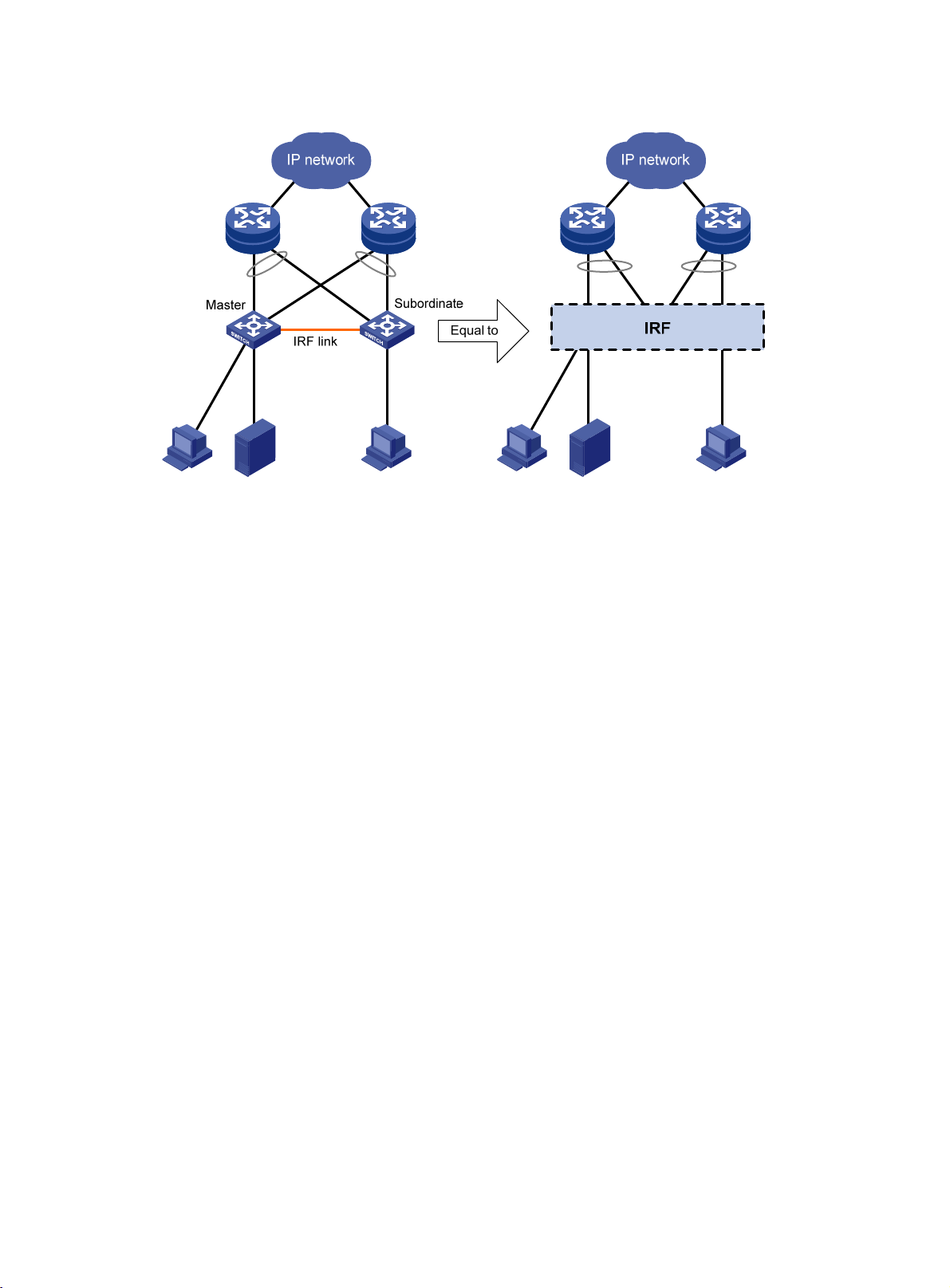
Figure 1 IRF application scenario
Basic concepts
This section describes the basic concepts you might encounter when you work with IRF.
IRF member roles
IRF uses two member roles: master and standby (called subordinate throughout the documentation).
When devices form an IRF fabric, they elect a master to manage and control the IRF fabric, and all the
other devices back up the master. When the master device fails, the other devices elect a new master
automatically. For more information about master election, see "Master election."
IRF member ID
An IRF fabric uses member IDs to uniquely identify and manage its members. This member ID information
is included as the first part of interface numbers and file paths to uniquely identify interfaces and files in
an IRF fabric. For more information about interface and file path naming, see "Interface naming
co
nventions" and "File system naming conventions."
If t
wo devices have the same IRF member ID, they cannot form an IRF fabric. If the IRF member ID of a
device has been used in an IRF fabric, the device cannot join the fabric.
IRF port
An IRF port is a logical interface for the connection between IRF member devices. Every IRF-capable
device supports two IRF ports. The IRF ports are named IRF-port n/1 and IRF-port n/2, where n is the
member ID of the device. The two IRF ports are referred to as IRF-port 1 and IRF-port 2 in this book.
2
To use an IRF port, you must bind a minimum of one physical interface to it. The physical interfaces
ass ig ne d to an IRF port form an aggregate I RF link automatically. An IRF port g oes down only i f all its I RF
physical interfaces are down.
IRF physical interface
IRF physical interfaces connect IRF member devices and must be bound to an IRF port. They forward the
IRF protocol packets between IRF member devices and the data packets that must travel across IRF
member devices.
For more information about physical interfaces that can be used for IRF links, see "IRF physical interface
r
equirements."
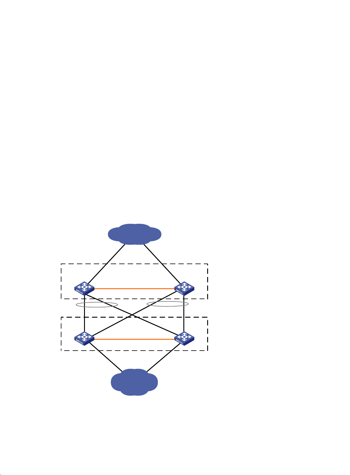
IRF domain ID
One IRF fabric forms one IRF domain. IRF uses IRF domain IDs to uniquely identify IRF fabrics and prevent
IRF fabrics from interfering with one another.
As shown in Figure 2, D
evice A and Device B form IRF fabric 1, and Device C and Device D form IRF
fabric 2. Both fabrics use the LACP aggregate links between them for MAD. When a member device
receives an extended LACPDU for MAD, it checks the domain ID to see whether the packet is from the
local IRF fabric. Then, the device can handle the packet correctly.
Figure 2 A network that contains two IRF domains
Core network
Device A
Device C
IRF 1 (domain 10)
IRF link
IRF 2 (domain 20)
IRF link
Device B
Device D
Access network
3
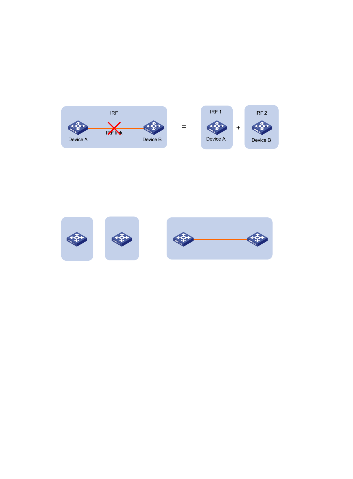
IRF split
IRF split occurs when an IRF fabric breaks up into two or more IRF fabrics because of IRF link failures, as
shown in Figure 3. T
forwarding problems on the network. To quickly detect a multi-active collision, configure a minimum of
one MAD mechanism (see "IRF multi-active detection")
Figure 3 IRF split
IRF merge
IRF merge occurs when two split IRF fabrics reunite or when two independent IRF fabrics are united, as
shown in Figure 4.
he split IRF fabrics operate with the same IP address and cause routing and
.
Figure 4 IRF merge
IRF 1
+
Device A
IRF 2
Device B
=
Device A Device B
Member priority
Member priority determines the possibility of a member device to be elected the master. A member with
higher priority is more likely to be elected the master.
The default member priority is 1. You can change the member priority of a device to affect the master
election result.
Interface naming conventions
An interface is named in the chassis-number/slot-number/port-index format.
• chassis-number—IRF member ID of the switch. This argument defaults to 1. The IRF member ID
always takes effect regardless of whether the switch is part of an IRF fabric.
IRF
IRF link
• slot-number—Slot number of the front panel. This argument is fixed at 0.
• port-index—Index of the port on the device. Port index depends on the number of ports available
on the device. To identify the index of a port, look at its port index mark on the chassis.
Look at the following examples:
4

• On the standalone switch Sysname, GigabitEthernet 1/0/1 represents the first port on the device.
Set its link type to trunk, as follows:
<Sysname> system-view
[Sysname] interface gigabitethernet 1/0/1
[Sysname-GigabitEthernet1/0/1] port link-type trunk
• On the IRF fabric Master, GigabitEthernet 3/0/1 represents the first fixed port on member device
3. Set its link type to trunk, as follows:
<Master> system-view
[Master] interface gigabitethernet 3/0/1
[Master-GigabitEthernet3/0/1] port link-type trunk
File system naming conventions
On a standalone device, you can use its storage device name to access its file system. For more
information about storage device naming conventions, see Fundamentals Configuration Guide.
On an IRF fabric, you can use the storage device name to access the file system of the master. To access
the file system of any other member device, use the name in the slotmember-ID#storage-device-name
format. For example:
To access the test folder under the root directory of the flash memory on the master device:
<Master> mkdir test
Creating directory flash:/test... Done.
<Master> dir
Directory of flash:
0 -rw- 43548660 Jan 01 2011 08:21:29 system.ipe
1 drw- - Jan 01 2011 00:00:30 diagfile
2 -rw- 567 Jan 02 2011 01:41:54 dsakey
3 -rw- 735 Jan 02 2011 01:42:03 hostkey
4 -rw- 36 Jan 01 2011 00:07:52 ifindex.dat
5 -rw- 0 Jan 01 2011 00:53:09 lauth.dat
6 drw- - Jan 01 2011 06:33:55 log
7 drw- - Jan 02 2000 00:00:07 logfile
8 -rw- 23724032 Jan 01 2011 00:49:47 switch-cmw710-system.bin
9 drw- - Jan 01 2000 00:00:07 seclog
10 -rw- 591 Jan 02 2011 01:42:03 serverkey
11 -rw- 4609 Jan 01 2011 00:07:53 startup.cfg
12 -rw- 3626 Jan 01 2011 01:51:56 startup.cfg_bak
13 -rw- 78833 Jan 01 2011 00:07:53 startup.mdb
14 drw- - Jan 01 2011 00:15:48 test
25 drw- - Jan 01 2011 04:16:53 versionInfo
524288 KB total (365292 KB free)
To create and access the test folder under the root directory of the flash memory on member device 3:
<Master> mkdir slot3#flash:/test
Creating directory slot3#flash:/test... Done.
<Master> cd slot3#flash:/test
<Master> pwd
slot3#flash:/test
5

Or:
<Master> cd slot3#flash:/
<Master> mkdir test
Creating directory slot3#flash:/test... Done.
To copy the file test.ipe on the master to the root directory of the flash memory on member device 3:
# Display the current working path. In this example, the current working path is the root directory of the
flash on member device 3.
<Master> pwd
slot3#flash:
# Change the current working path to the root directory of the flash memory on the master device.
<Master> cd flash:/
<Master> pwd
flash:
# Copy the file to member device 3.
<Master> copy test.ipe slot3#flash:/
Copy flash:/test.ipe to slot3#flash:/test.ipe?[Y/N]:y
Copying file flash:/test.ipe to slot3#flash:/test.ipe... Done.
Configuration synchronization
IRF uses a strict running-configuration synchronization mechanism. In an IRF fabric, all devices obtain
and run the running configuration of the master. Configuration changes are automatically propagated
from the master to the remaining devices. The configuration files of these devices are retained, but the
files do not take effect. The devices use their own startup configuration files only after they are removed
from the IRF fabric.
For more information about configuration management, see Fundamentals Configuration Guide.
Master election
Master election occurs each time the IRF fabric topology changes in the following situations:
• The IRF fabric is established.
• The master device fails or is removed.
• The IRF fabric splits.
• Independent IRF fabrics merge.
NOTE:
Master election does not occur when two split IRF fabrics merge.
Master election selects a master in descending order:
1. Current master, even if a new member has higher priority.
When an IRF fabric is being formed, all members consider themselves as the master. This rule is
skipped.
2. Member with higher priority. If all members have the same priority, this rule is skipped.
3. Member with the longest system uptime.
6

Two members are considered to start up at the same time if the difference between their startup
times is equal to or less than 10 minutes. For these members, the next tiebreaker applies.
4. Member with the lowest CPU MAC address.
For the setup of a new IRF fabric, the subordinate devices must reboot to complete the setup after the
master election.
For an IRF merge, devices must reboot if they are in the IRF fabric that fails the master election.
IRF multi-active detection
An IRF link failure causes an IRF fabric to split in two IRF fabrics operating with the same Layer 3 settings,
including the same IP address. To avoid IP address collision and network problems, IRF uses multi-active
detection (MAD) mechanisms to detect the presence of multiple identical IRF fabrics, handle collisions,
and recover from faults.
Multi-active handling procedure
The multi-active handling procedure includes detection, collision handling, and failure recovery.
Detection
The device's MAD implementation detects active IRF fabrics with the same Layer 3 global configuration
by extending the LACP, BFD, ARP, or IPv6 ND protocol.
These MAD mechanisms identify each IRF fabric with a domain ID and an active ID (the member ID of
the master). If multiple active IDs are detected in a domain, MAD determines that an IRF collision or split
has occurred.
You can use these mechanisms concurrently in an IRF fabric, depending on the network topology.
IMPORTANT:
LACP MAD handles collisions differently than BFD MAD, ARP MAD, and ND MAD. To avoid conflicts, do
not enable LACP MAD together with any of those mechanisms in an IRF fabric. However, you can use BFD
MAD, ARP MAD, and ND MAD together.
For a comparison of these MAD mechanisms, see "Configuring MAD."
Collision handling
When MAD detects a multi-active collision, it sets all IRF fabrics except one to the Recovery state. The
fabric that is not placed in Recovery state can continue to forward traffic. The Recovery-state IRF fabrics
are inactive and cannot forward traffic.
LACP MAD uses the following process to handle a multi-active collision:
1. Compares the number of members in each fabric.
2. Sets all fabrics to the Recovery state except the one that has the most members.
3. Compares the member IDs of the masters if all IRF fabrics have the same number of members.
4. Sets all fabrics to the Recovery state except the one that has the lowest numbered master.
5. Shuts down all physical network ports in the Recovery-state fabrics except for the following ports:
{ IRF physical interfaces.
{ Ports you have specified with the mad exclude interface command.
7

In contrast, BFD MAD, ARP MAD, and ND MAD do not compare the number of members in fabrics.
These MAD mechanisms use the following process to hand a multi-active collision:
1. Compare the member IDs of the masters in the IRF fabrics.
2. Set all fabrics to the Recovery state except the one that has the lowest numbered master.
3. Take the same action on the network ports in Recovery-state fabrics as LACP MAD.
Failure recovery
To merge two split IRF fabrics, first repair the failed IRF link and remove the IRF link failure.
• If the IRF fabric in Recovery state fails before the failure is recovered, repair the failed IRF fabric and
the failed IRF link.
• If the active IRF fabric fails before the failure is recovered, enable the inactive IRF fabric to take over
the active IRF fabric. Then, recover the MAD failure.
LACP MAD
As shown in Figure 5, LACP MAD has the following requirements:
• Every IRF member must have a link with an intermediate device.
• All the links form a dynamic link aggregation group.
• The intermediate device must be a device that supports extended LACP for MAD.
The IRF member devices send extended LACPDUs with TLVs that convey the domain ID and the active ID
of the IRF fabric. The intermediate device transparently forwards the extended LACPDUs received from
one member device to all the other member devices.
• If the domain IDs and active IDs in the extended LACPDUs sent by all the member devices are the
same, the IRF fabric is integrated.
• If the extended LACPDUs convey the same domain ID but different active IDs, a split has occurred.
LACP MAD handles this situation as described in "Collision handling."
8
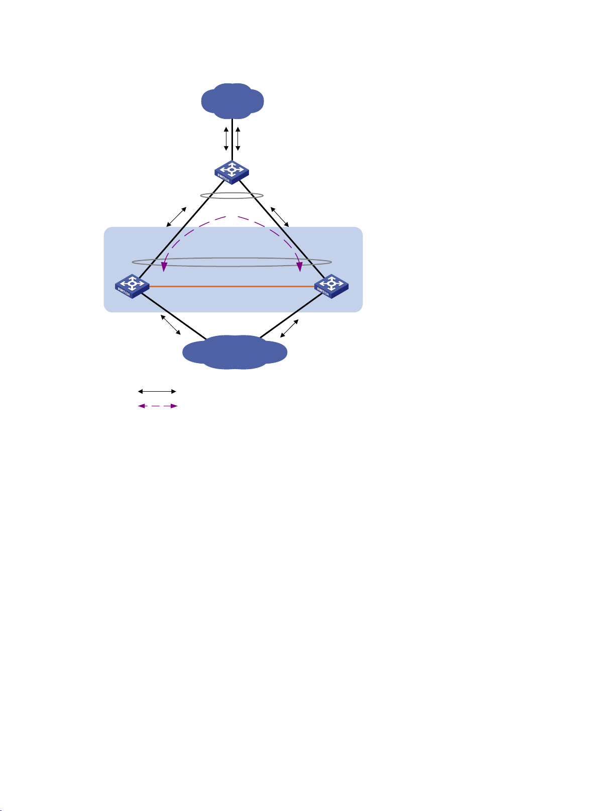
Figure 5 LACP MAD application scenario
Customer
premise
network
Device
LACP-enabled dynamic
link aggregation
IRF
LACP-enabled dynamic
link aggregation
IRF link
Master
Subordinate
BFD MAD
BFD MAD can work with or without an intermediate device. Figure 6 shows a typical BFD MAD
application scenario.
To use BFD MAD:
• Set up dedicated BFD MAD link between each pair of IRF members or between each IRF member
and the intermediate device. Do not use the BFD MAD links for any other purposes.
• Assign the ports connected by BFD MAD links to the same VLAN.
• Create a VLAN interface for the VLAN, and assign a MAD IP address to each member on the VLAN
interface.
The MAD addresses identify the member devices and must belong to the same subnet.
With BFD MAD, the master attempts to establish BFD sessions with other member devices by using its
MAD IP address as the source IP address:
Internet
Common traffic path
LACP MAD traffic path
• If the IRF fabric is integrated, only the MAD IP address of the master takes effect. The master cannot
establish a BFD session with any other member. If you execute the display bfd session command,
the state of the BFD sessions is Down.
• When the IRF fabric splits, the IP addresses of the masters in the split IRF fabrics take effect. The
masters can establish a BFD session. If you execute the display bfd session command, the state of
the BFD session between the two devices is Up.
9
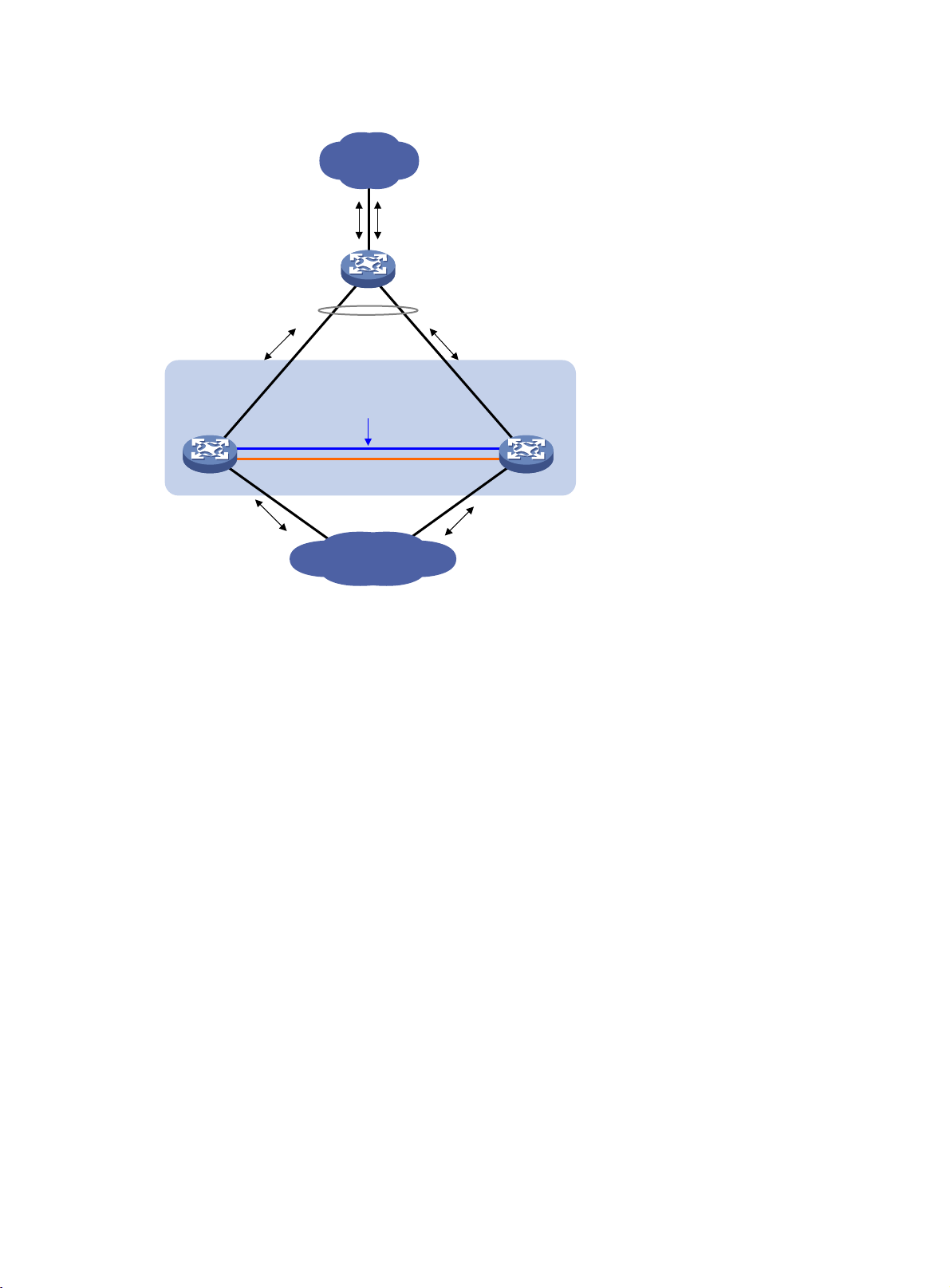
Figure 6 BFD MAD application scenario
Customer
premise
network
Device
Link aggregation
IRF
VLAN 2
192.168.1.2/24
BFD MAD link
VLAN 2
192.168.1.3/24
Master
ARP MAD
ARP MAD detects multi-active collisions by using extended ARP packets that convey the IRF domain ID
and the active ID.
You can set up ARP MAD links between neighbor IRF member devices, or between each IRF member
device and an intermediate device (see Figure 7)
spanning tree feature between the IRF fabric and the intermediate device.
IRF link
Subordinate
Internet
. If an i ntermediate device is used, you must also run t he
10
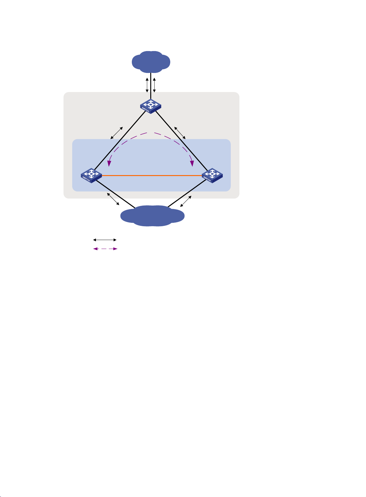
Figure 7 ARP MAD application scenario
Customer
premise
network
STP domain (all devices
Device
must run the spanning
tree feature)
IRF
IRF link
Master
Subordinate
Each IRF member compares the domain ID and the active ID in incoming extended ARP packets with its
domain ID and active ID:
• If the domain IDs are different, the extended ARP packet is from a different IRF fabric. The device
does not continue to process the packet with the MAD mechanism.
• If the domain IDs are the same, the device compares the active IDs:
{ If the active IDs are different, the IRF fabric has split.
{ If the active IDs are the same, the IRF fabric is integrated.
ND MAD
ND MAD detects multi-active collisions by using the ND protocol's NS packets to transmit the IRF domain
ID and the active ID.
You can set up ND MAD links between neighbor IRF member devices or between each IRF member
device and an intermediate device (see Figure 8)
spanning tree protocol between the IRF fabric and the intermediate device.
Internet
Common traffic path
Extended ARP traffic path
. If an i ntermediate device is used, you must also run t he
11

Figure 8 ND MAD application scenario
Customer
premise
network
STP domain (all devices
Device
must run the spanning
tree feature)
IRF
IRF link
Master
Subordinate
Internet
Common traffic path
Extended ND traffic path
Each IRF member device compares the domain ID and the active ID in incoming NS packets with its
domain ID and active ID:
• If the domain IDs are different, the NS packet is from a different IRF fabric. The device does not
continue to process the packet with the MAD mechanism.
• If the domain IDs are the same, the device compares the active IDs:
{ If the active IDs are different, the IRF fabric has split.
{ If the active IDs are the same, the IRF fabric is integrated.
12

Configuring IRF
To ensure a successful IRF setup, read the configuration restrictions and guidelines carefully before you
connect and set up an IRF fabric.
General restrictions and configuration guidelines
Software requirements
All IRF member devices must run the same software image version. Make sure the software auto-update
function is enabled on all member devices.
IRF physical interface requirements
Use SFP+ ports on the front panel for IRF connection.
Selecting transceiver modules and cables
When you select transceiver modules and cables, follow these restrictions and guidelines:
• Use Category 6A (or above) twisted-pair cables to connect 10GBASE-T ports for a short-distance
connection.
• Use SFP+ DAC cables to connect SFP+ ports for a short-distance connection.
• Use SFP+ transceiver modules and fibers to connect SFP+ ports for a long-distance connection.
• The transceiver modules at the two ends of an IRF link must be the same type.
For more information about the SFP+ ports, SFP+ DAC cables, and SFP+ transceiver modules, see the
switch installation guide. For detailed information about the SFP+ transceiver modules, see HP
Comware-Based Devices Transceiver Modules User Guide.
NOTE:
The SFP+ modules and SFP+ DAC cables available for the switch are subject to change over time. For the
most up-to-date list of SFP+ modules and DAC cables, contact HP technical support or marketing staff.
13

IRF physical interface location and binding restrictions
Device model
• HP 5130-24G-4SFP+ EI Switch
(JG932A)
• HP 5130-24G-4SFP+ EI Brazil
Switch (JG975A)
• HP 5130-24G-PoE+-4SFP+
(370W) EI Switch (JG936A)
• HP 5130-24G-PoE+-4SFP+
(370W) EI Brazil Switch
(JG977A)
• HP 5130-24G-SFP-4SFP+ EI
Switch (JG933A)
• HP 5130-24G-2SFP+-2XGT EI
Switch (JG938A)
• HP
5130-24G-PoE+-2SFP+-2XGT
(370W) EI Switch (JG940A)
• HP 5130-48G-4SFP+ EI
Switch (JG934A)
• HP 5130-48G-4SFP+ EI Brazil
Switch (JG976A)
• HP 5130-48G-PoE+-4SFP+
(370W) EI Switch (JG937A)
• HP 5130-48G-PoE+-4SFP+
(370W) EI Brazil Switch
(JG978A)
Candidate IRF physical
interfaces
The four SFP+ ports on the front
panel.
The two SFP+ ports and the two
10GBASE-T ports on the front
panel.
The four SFP+ ports (in two
groups) on the front panel:
• SFP+ ports 49 and 50 in one
group.
• SFP+ ports 51 and 52 in the
other group.
Requirements
No binding restrictions. You can bind
the four ports as needed to any IRF
ports.
No binding restrictions. You can bind
the four ports as needed to any IRF
ports.
If an IRF port contains multiple IRF
physical interfaces, the physical
interfaces must belong to the same
group.
Ports in a port group can be bound to
different IRF ports as IRF physical
interfaces.
• HP 5130-48G-2SFP+-2XGT EI
Switch (JG939A)
• HP
5130-48G-PoE+-2SFP+-2XGT
(370W) EI Switch (JG941A)
Connecting IRF ports
When you connect two neighboring IRF members, connect the physical interfaces of IRF-port 1 on one
member to the physical interfaces of IRF-port 2 on the other.
The two SFP+ ports and the two
10GBASE-T ports on the front
panel.
The ports are grouped: SFP+ ports
in one group and the 10GBASE-T
ports in another group.
14
If an IRF port contains multiple IRF
physical interfaces, the physical
interfaces must belong to the same
group.
Ports in a port group can be bound to
different IRF ports as IRF physical
interfaces.
 Loading...