

Page 1
HP ProCurve
g
Overview
6120XG Blade Switch
Installation Instructions
for HP c-Class BladeSystem
This card provides instructions for installing an HP ProCurve 6120XG
Blade Switch for c-Class BladeSystem in an HP c-Class BladeSystem
enclosure.
Kit contents
HP ProCurve 6120XG Blade Switch
Console cable (USB A to USB mini-AB)
Customer Support/Warranty booklet
License documentation
This document
IMPORTANT: Only use HP-approved pluggable SFP+ or SFP
optical transceiver modules or SFP+ direct attach cables. For
more information, see the QuickSpecs on the HP website
(http://www.hp.com/go/bladesystem/interconnects
HP ProCurve 6120XG Blade Switch
).
© Copyright 2009 Hewlett-Packard Development Company, L.P.
The information contained herein is subject to change without notice. The
only warranties for HP products and services are set forth in the express
warranty statements accompanying such products and services. Nothing
herein should be construed as constituting an additional warranty. HP shall
not be liable for technical or editorial errors or omissions contained herein.
Microsoft is a U.S. re
Part Number 539957-001
September 2009 (First Edition)
istered trademark of Microsoft Corporation.
Additional information
For more information on the association between the server blade
mezzanine connectors and the interconnect bays, see the HP
BladeSystem enclosure setup and installation guide that ships with
the enclosure. During server blade installation, the location of the
mezzanine card determines the installation location of the switch
modules.
For specific switch port connection information for each blade, see
the HP BladeSystem enclosure setup and installation guide that ships
with the enclosure. Connections differ by blade type.
Installation guidelines
Observe the following guidelines:
All HP ProCurve switches in the enclosure require valid and
unique IP addresses before they can be accessed via Ethernet.
By default DHCP is enabled on these switches, so the switch
management interface can get IP credentials from the DHCP
server on the attached Ethernet network. If EBIPA is enabled on
the Onboard Administrator (OA) of the enclosure, OA will
assign an IP address to the switch from its configured IP
address range, so that switch can be accessed from the OA
Ethernet interface. If EBIPA is disabled but DHCP service is
available on the network attached to the OA Ethernet interface,
then the switch gets its IP address assigned from the attached
network. Any IP host on that network can access the switch at
this point. If the DHCP service is not available on the attached
network, the user can assign valid IP credentials from the
Page 2
switch CLI, accessing it via serial interface attached to OA
and/or USB interface attached to the blade.
When using optional transceiver modules or direct attach
cables, order the modules and cables separately. For more
information, see the QuickSpecs on the HP website
(http://www.hp.com/go/bladesystem/interconnects
).
For more information on BladeSystem port mapping, see the
HP BladeSystem enclosure setup and installation guide that
shipped with the enclosure.
For the most current product information, see the release notes
at http://www.hp.com/go/bladesystem/documentation
Firmware requirements
.
Always install the most current firmware or software for the following
items:
Server blade system ROMs
Ethernet mezzanines
HP BladeSystem Onboard Administrator
HP ProCurve blade switch
For additional information on required firmware or software versions
and to download firmware or software updates, see the HP website:
1. Go to http://www.hp.com/#Support.
2. Cli
ck the “Download drivers and software” radio button.
3. Enter “6120XG” in the text box and click “Go”.
4. Click the link for your operating system.
5. Download the appropriate software or firmware.
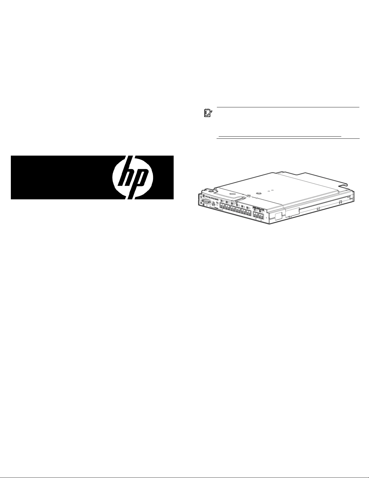
Front Panel
Item Description
1 Port 17 (10GBASE-CX4) *
2 Console port (USB 2.0 mini-AB connector)
3 Clear button
4 Port 17 SFP+ (10-GbE) slot * †
5 Port 18 SFP+ (10-GbE) slot †
6 Port 19 SFP+ (10-GbE) slot †
7 Port 20 SFP+ (10-GbE) slot †
8 Port 21 SFP+ (10-GbE) slot †
9 Port 22 SFP+ (10-GbE) slot †
10 Port 23 SFP+ (10-GbE) slot * †
11 Port 24 SFP+ (10-GbE) slot * †
12 Reset button (recessed)
* Dual-personality port. See explanation below.
†
Supports 10GBASE-SR SFP+, 10GBASE-LR SFP+, 10GBASE-LRM
SFP+, 1000BASE-T SFP, 1000BASE-SX SFP, and 1000BASE-LX SFP
pluggable optical transceiver modules.
Dual-personality ports
Port 17 consists of a CX4 port multiplexed with an SFP+ port. Only
one may be active. The SFP+ port takes precedence: if it contains a
module, it is the active port and the CX4 port is inactive.
Ports 23 and 24 are each multiplexed with inter-switch link ports
on the blade switch’s backplane. Either the SFP+ port on the front
panel or the backplane port can be active, but both can not be
active at the same time. The SFP+ port on the frontplane takes
precedence: if it contains a module, it is the active port and its
corresponding backplane port is inactive. Refer to the Installation
and Getting Started Guide for more information.
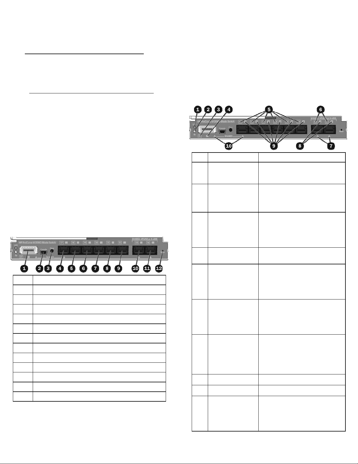
LEDs
Item LED description Status
1 Module locator
(UID)
2 Module status
(health)
Blue = Module ID selected
Off = Module ID not selected
Green = Normal operation
Amber = Fault
Off = Power off
3 Port 17 status
(10GBASE-CX4)
Green = Port is connected to the
network.
Amber = Fault
Off = Not connected
4 Port 17 activity
Green flashing = Activity
(10GBASE-CX4)
5
Port 17–22 status
(SFP+ connector)
Green = Port is connected to the
network.
Amber = Fault
Off = Not connected
6
Port 23–24 status
Green = Port is connected to the
network.
Amber = Fault
Off = Not connected
7
Port 23
multiplexed port
status
–24
Green = Frontplane port is active.
Internal (backplane) link is inactive.
Off = Frontplane port is inactive.
Internal (backplane) link may be
active.
8
Port 23–24 activity
9
Port 17–22 activity
10 Port 17 multiplexed
port status
Green flashing = Activity
Green flashing = Activity
Either the CX4 port or the SFP+ port
may be active, but not both.
Green = Port is active.
Off = Port is inactive.
Page 3

Installing the HP ProCurve 6120XG Blade Switch
If there is only one blade switch in the chassis, it must occupy a slot
on the left-hand side of the chassis (as you face the back of the
chassis). If there is more than one blade switch in the chassis, the
configuration rules can be somewhat complex; refer to the
Installation and Getting Started Guide for the blade switch for more
detail.
Follow these steps to install a blade switch module in your chassis:
NOTE: The HP ProCurve 6120XG Blade Switch module
can be used in an HP BladeSystem c7000 Enclosure or an
HP BladeSystem c3000 Enclosure. The illustrations in this
document show the blade switch being installed in a
c7000 enclosure.
1. Remove the interconnect blank.
3. Install the blade switch into the interconnect bay.
A green Module Status (“health”) LED indicates a
successful installation. If the Module Status LED is amber
or is off, see the “Troubleshooting” section of the HP
BladeSystem enclosure setup and installation guide for
more information.
2. Prepare the HP ProCurve 6120XG Blade Switch for
installation.
4. Connect network cables to the blade switch as desired.
Accessing the blade switch from the HP BladeSystem Onboard Administrator
These instructions assume that you have already set up the HP
BladeSystem Onboard Administrator (OA) using the First Time Setup
Wizard. See the HP BladeSystem Onboard Administrator User
Guide for details on OA setup. For information on OA command line
interface (CLI) commands, see the HP BladeSystem Onboard
Administrator Command Line Interface User Guide. Both guides are
available at http://www.hp.com/go/bladesystem/documentation
.
1. Connect a workstation or laptop computer to the serial port
on the c3000/c7000 OA module using a null-modem
serial cable (RS-232).
2. Using a terminal program (such as HyperTerminal or
TeraTerm), open a connection to the serial port using
connection parameters of 9600, 8, N, 1.
3. Press Enter. OA prompts you for login information.
4. Enter a valid username and password. The OA system
prompt appears.
5. Enter the command:
connect interconnect <bay_number>
where <bay_number> is the number of the bay
containing the blade switch. OA connects you to the
initial screen of the blade switch CLI.
6. Press Enter. The blade switch CLI prompt appears. You
are now ready to enter blade switch CLI commands.
See the paragraphs below for instructions for assigning an IP
address to the blade switch. Refer to the Management and
Configuration Guide for HP ProCurve 6120 Blade Switches for more
Page 4

detailed information on configuring the blade switch. The complete
manual set for the blade switch software is available at
http://www.hp.com/go/bladesystem/documentation
.
Accessing the blade switch via the mini USB interface (out of band)
The blade switch console supports out-of-band access via direct
connection to the mini USB console port from a Windows computer.
To communicate with the blade switch:
1. Download the USB driver onto the PC. To find the driver:
a. Go to http://www.hp.com/#Support
b. Click the “Download drivers and software”
radio button.
c. Enter “6120XG” in the text box and click
“Go”.
d. Click the link for your operating system.
e. Download the Utilities package.
2. Install the driver by double-clicking the
HPProCurve_USBConsole.msi file.
3. Connect the small end of the supplied USB console cable
to the mini USB port.
4. Connect the standard end of the supplied USB console
cable to a workstation or laptop computer. The computer
will recognize the presence of a new USB device and
load the driver for it.
5. Using a terminal program (such as HyperTerminal or
TeraTerm), open a connection to the USB port. (By default
this port will appear as COM4.)
6. Press Enter twice. The blade switch CLI prompt appears.
You are now ready to enter blade switch commands.
See the paragraphs below for instructions for assigning an IP
address to the blade switch. Refer to the Management and
Configuration Guide for HP ProCurve 6120 Blade Switches for more
detailed information on using CLI commands to set up the blade
switch. The complete manual set for the blade switch software is
available at http://www.hp.com/go/bladesystem/documentation
.
.
Accessing the blade switch from the Ethernet interface (in band)
The blade switch console supports in-band access via the data ports
using Telnet from a PC or UNIX computer on the network, and a VT100 terminal emulator. This method requires the blade switch to
have an IP address, subnet mask, and default gateway. The IP
address, subnet mask, and default gateway can be supplied by a
DHCP or Bootp server, or you can manually configure them using the
command line interface (CLI). By default the blade switch gets its IP
address via DHCP/Bootp; see the next section for instructions on
manually configuring a static IP address.
1. Verify network connectivity between the blade switch and
your workstation or laptop computer using a “ping”
command.
2. Using a terminal program (such as HyperTerminal or
TeraTerm), open a connection using the blade switch’s IP
address, Telnet protocol, and port 23.
3. Press Enter twice. The blade switch CLI prompt appears.
You are now ready to issue blade switch commands.
For complete information on the blade switch CLI commands see the
blade switch software manuals, which are available at
http://www.hp.com/go/bladesystem/documentation
The blade switch can simultaneously support one out-of-band console
session through the console port and one in-band Telnet console
session.
.
Assigning an IP address to the blade switch
By default the blade switch tries to acquire an IP address from a
DHCP or Bootp server. You can configure an IP address for the
blade switch using the command line interface (CLI), via the
Onboard Administrator or the blade switch’s mini USB port.
To set a static IP address manually:
1. From the operator’s CLI prompt (>) on the blade switch
enter:
enable
and supply a username and password if requested.
2. From the manager’s CLI prompt (#) on the blade switch
enter:
config
3. Specify the VLAN of the port that attaches to the network.
(By default all ports are in VLAN 1.)
vlan <vlan_id>
4. Enter an IP address and subnet mask for the switch. (Both
the IP address and subnet mask are in x.x.x.x format.)
ip address <ip_address> <subnet_mask>
5. Enter a default gateway ip address (in x.x.x.x format).
ip default-gateway <ip_address>
6. You can return to the operator or manager prompt using
a series of exit commands.
Technical Support
For technical support, go to www.hp.com/support.
To communicate with a blade switch that has an IP address, subnet
mask, and default gateway:
 Loading...