

Page 1
ConcordeHP Plus
Home
Find...
Go To..
Automatic Carpet Extractor
Model No.:
608349
608935 – Pac
609256 – Can. Pac
Operator and Parts Manual
NOBLES
12875 RANSOM STREET
HOLLAND MI 49424 U.S.A.
CUSTOMER S E RVICE: 1-800-365-6625
FAX: 1–800–678–4240
OUTSIDE U.S. : 1–616–786–2330
608416
Rev. 00 (01-00)
Page 2

OPERATION
Home
Find...
Go To..
This manual is furnished with each new model. It
provides necessary operation and machine
maintenance instructions and an illustrated parts list.
Read this manual completely and understand the
machine before operating or servicing it.
This machine will provide excellent service. However,
the best results will be obtained at minimum costs if:
The machine is operated with reasonable care.
The machine is maintained regularly - per the
machine care instructions provided.
The machine is maintained with manufacturer
supplied or equivalent parts.
When ordering replacement parts, use the Parts Lists
in this manual. Before ordering parts or supplies, be
sure to have your machine model number and serial
number handy. Parts and supplies may be ordered by
phone or mail from any Authorized Service Center or
Distributor.
MACHINE DATA
Please fill out at time of installation for future reference.
Model No.- Install. Date - / /
Serial No.-
2000 Tennant Company Printed in U.S.A
Nobles is a registered United States trademark of Tennant Company.
Specifications and parts are subject to change without notice.
TABLE OF CONTENTS
SAFETY PRECAUTIONS 3. . . . . . . . . . . . . . . . . . . . . . .
MACHINE COMPONENTS 4. . . . . . . . . . . . . . . . . . . . . .
MACHINE PANEL SYMBOLS 4. . . . . . . . . . . . . . . . . . . .
MACHINE INSTALLATION 5. . . . . . . . . . . . . . . . . . . . . .
UNCRATING MACHINE 5. . . . . . . . . . . . . . . . . . . . . .
INSTALLING BATTERIES 6. . . . . . . . . . . . . . . . . . . .
MACHINE SETUP 6. . . . . . . . . . . . . . . . . . . . . . . . . . . . . .
FILLING SOLUTION TANK 6. . . . . . . . . . . . . . . . . . .
MACHINE OPERATION 6. . . . . . . . . . . . . . . . . . . . . . . . .
PRE–OPERATION CHECKS 6. . . . . . . . . . . . . . . . .
TRANSPORTING MACHINE 6. . . . . . . . . . . . . . . . . .
CLEANING WITH MACHINE 7. . . . . . . . . . . . . . . . . .
WHILE OPERATING MACHINE 8. . . . . . . . . . . . . . .
CIRCUIT BREAKER CONSOLE 9. . . . . . . . . . . . . . .
ADJUSTING BRUSH HEIGHT 9. . . . . . . . . . . . . . . .
ACCESSORY TOOL SETUP AND
OPERATION (OPTIONS) 10. . . . . . . . . . . . . . . . . . . . .
DRAINING TANKS 10. . . . . . . . . . . . . . . . . . . . . . . . . . .
DRAINING RECOVERY TANK 10. . . . . . . . . . . . . .
DRAINING SOLUTION TANK 11. . . . . . . . . . . . . . . .
BATTERY CHARGING 11. . . . . . . . . . . . . . . . . . . . . . . . .
MACHINE MAINTENANCE 12. . . . . . . . . . . . . . . . . . . .
TO ACCESS INTERNAL COMPONENTS 12. . . .
HOUR METER 13. . . . . . . . . . . . . . . . . . . . . . . . . . . .
DAILY MAINTENANCE 13. . . . . . . . . . . . . . . . . . . .
WEEKLY MAINTENANCE 13. . . . . . . . . . . . . . . . . .
MONTHLY MAINTENANCE 13. . . . . . . . . . . . . . . .
QUARTERLY MAINTENANCE 13. . . . . . . . . . . . . .
BATTERY MAINTENANCE 14. . . . . . . . . . . . . . . . .
DRIVE CHAIN MAINTENANCE 14. . . . . . . . . . . . .
BRUSH BELT MAINTENANCE 14. . . . . . . . . . . . . .
PLUMBING SYSTEM MAINTENANCE 15. . . . . . .
SOLUTION FILTER MAINTENANCE 15. . . . . . . . .
SPRAY BAR AND SPRAY TIP MAINTENANCE 16
TRANSPORTING MACHINE 16. . . . . . . . . . . . . . . . . .
STORING MACHINE 16. . . . . . . . . . . . . . . . . . . . . . . . .
TROUBLE SHOOTING 17. . . . . . . . . . . . . . . . . . . . . . .
SPECIFICATIONS 19. . . . . . . . . . . . . . . . . . . . . . . . . . .
PARTS LIST
UPPER HOUSING GROUP 20. . . . . . . . . . . . . . . . .
MAIN CHASSIS GROUP 22. . . . . . . . . . . . . . . . . . .
CONTROL CONSOLE GROUP 24. . . . . . . . . . . . .
DRIVE GROUP 26. . . . . . . . . . . . . . . . . . . . . . . . . . .
PLUMBING SYSTEM GROUP 28. . . . . . . . . . . . . .
BRUSH HEAD GROUP 30. . . . . . . . . . . . . . . . . . . .
PUMP BREAKDOWN 32. . . . . . . . . . . . . . . . . . . . . .
SPRAY BAR GROUP 33. . . . . . . . . . . . . . . . . . . . . .
ELECTRICAL DIAGRAMS 34. . . . . . . . . . . . . . . . . . . .
OPTIONS
13 CM (5”) HAND TOOL 36. . . . . . . . . . . . . . . . . . .
SOLUTION AND VACUUM HOSES 36. . . . . . . . . .
FLOOR TOOL 37. . . . . . . . . . . . . . . . . . . . . . . . . . . .
2
Concorde HP Plus (01–00)
Page 3

SAFETY PRECAUTIONS
Home
Find...
Go To..
This machine is intended for commercial use. It is
designed to clean carpets in an indoor environment
and is not constructed for any other use.
All operators must read, understand and practice the
following safety precautions.
The following safety alert symbols are used throughout
this manual as indicated in their description.
WARNING: To warn of hazards or unsafe
practices which could result in severe personal
injury or death.
FOR SAFETY: To identify actions which must be
followed for safe operation of equipment.
The following information signals potentially dangerous
conditions to the operator or equipment:
FOR SAFETY:
1. Do not operate machine:
– Unless trained and authorized.
– Unless operation manual is read and
understood.
– In flammable or explosive areas unless
designed for use in those areas.
2. Before starting machine:
– Make sure all safety devices are in place
and operate properly.
3. When using machine:
– Go slow on inclines and slippery surfaces.
– Use care when reversing machine.
– Report machine damage or faulty
operation immediately.
– Follow mixing and handling instructions
on chemical containers.
OPERATION
4. Before leaving or servicing machine:
– Stop on level surface.
– Turn off machine.
– Pull out main circuit breaker button.
5. When servicing machine:
– Avoid moving parts. Do not wear loose
jackets, shirts, or sleeves.
– Block machine tires before jacking
machine up.
– Use hoist or jack of adequate capacity to
lift machine.
– Disconnect battery connections before
working on machine.
– Wear protective gloves when handling
batteries or battery cables.
– Avoid contact with battery acid.
– Use manufacturer supplied or approved
replacement parts.
WARNING: Batteries emit hydrogen gas.
Explosion or fire can result. Keep sparks and
open flame away. Keep battery compartment open
when charging.
WARNING: Flammable materials can cause
an explosion or fire. Do not use flammable
materials in tank(s).
WARNING: Flammable materials or reactive
metals can cause explosion or fire. Do not pick
up.
Concorde HP Plus (01–00)
3
Page 4
OPERATION
Home
Find...
Go To..
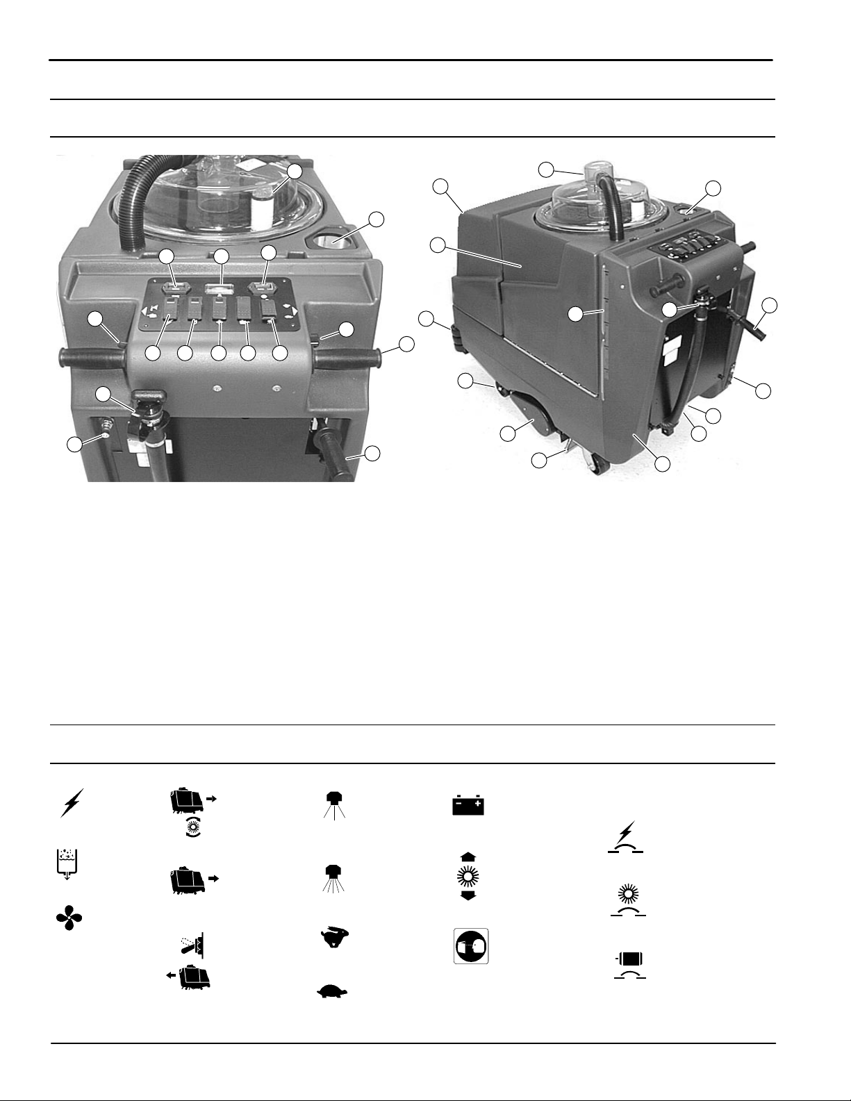
MACHINE COMPONENTS
28
11
16
10 4
2
5 6 7 8
3
15
1. Control Grips
2. Reverse Drive Trigger
3. Main Power Switch
4. Brush Pressure Meter
5. Pump Switch
6. Vacuum Switch
7. Clean Mode/Transport Mode Drive Switch
8. Restorative Cleaning/Interim Cleaning Switch
9. Transport Speed Control Knob
10. Battery Meter
11. Hour Meter
12. Circuit Breaker Panel
13. Brush Lift Lever
14. Brush Height Adjustment Knobs
21
24
17
25
9
13
19
1
23
22
26
20
15
27
17
13
12
14
18
15. Drain Hose
16. Floor Tool Accessory/Bleeder Hose Coupler
17. Solution Tank Fill Port
18. Inline Strainer Filter
19. Wall Roller Bumper
20. Vacuum Pickup Head
21. Recovery Tank Dome
22. Rotating Brush
23. Safety Wheels
24. Battery Compartment Hood
25 Recovery Tank
26. Solution Tank Gallon Marker
27. Solution Tank
28. Standpipe Screen
CONTROL PANEL SYMBOLS
Main
Power
Pump
Vacuum
Clean
Mode
Transport
Mode
Reverse
Interim
Cleaning
Restorative
Cleaning
Transport
Fast Speed
Transport
Slow Speed
Battery
Charge
Meter
Brush
Pressure
Meter
Read Manual
Before Operating
4
CIRCUIT BREAKER PANEL
Main Power
Circuit Breaker
Brush Motor
Circuit Breaker
Drive Motor
Circuit Breaker
Concorde HP Plus (01–00)
Page 5
MACHINE INSTALLATION
Home
Find...
Go To..
UNCRATING MACHINE
Carefully check carton for signs of damage. Report
damages at once to carrier.
Check carton contents list below. Contact your
distributor for missing items.
1 – Recovery Dome (stored in battery
compartment)
1 – Recovery Dome Vacuum Hose (stored in
recovery tank)
1 – Battery Tray
2 – Battery Cables (stored in battery
compartment)
1 – Pumpout Hose (stored in recovery tank)
1 – Standpipe Screen (stored in recovery tank)
1 – Solution Tank Fill Port Strainer (stored in
recovery tank)
1 – Spray Bar (installed on machine)
1 – Battery Charger (Included with Concorde
HP Plus Pac 608935) Packaged Separately
3 – 12V Batteries (Included with Concorde HP
Plus Pac 608935; not included with Pac
609256) Packaged Separately
ATTENTION: Battery installation must be
accomplished after removing machine from
shipping crate.
OPERATION
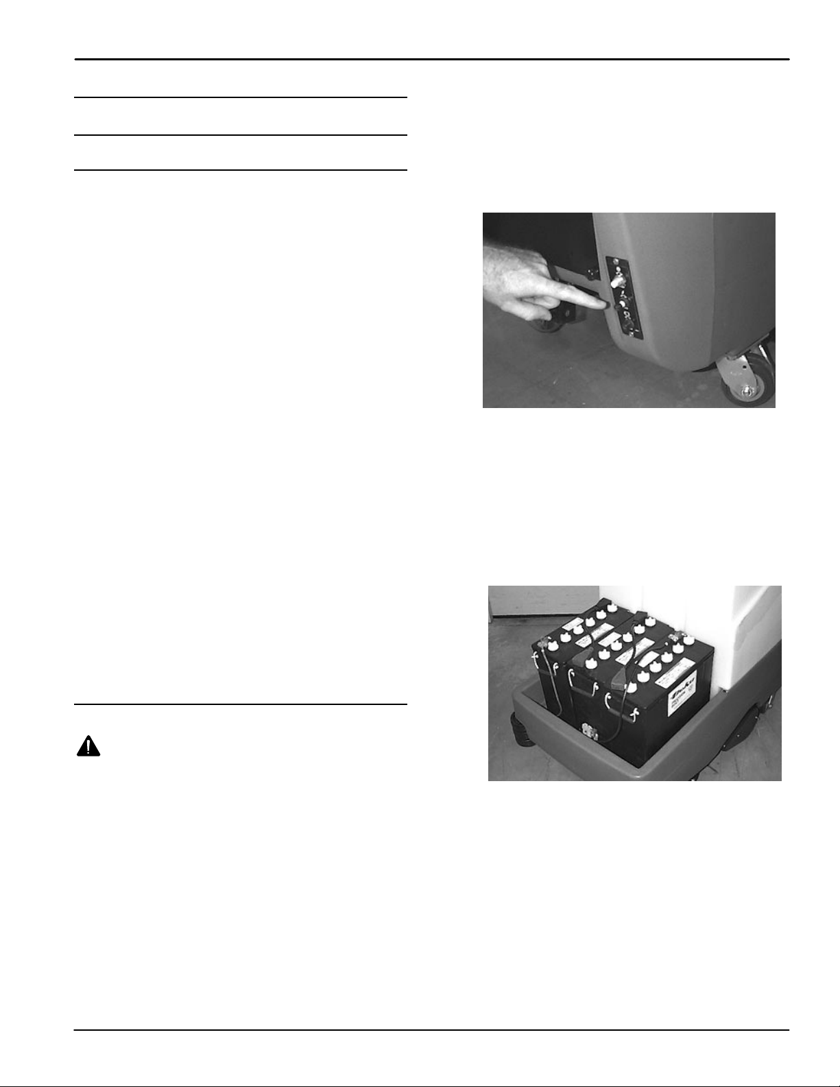
1. Before installing batteries pull out the main circuit
breaker button to shut off power to machine.
Circuit breaker panel is located at rear lower right
of machine (Figure 1).
FOR SAFETY: Before leaving or servicing
machine, stop on level surface, turn off machine
and pull out main circuit breaker button.
FIG. 1
2. Lift battery compartment hood off machine and
remove loose battery cables.
3. Carefully install batteries into battery tray with
negative posts towards back of machine.
(Figure 2).
ATTENTION: Be careful not to drop batteries into
compartment, battery and machine housing
damage may result.
ATTENTION: DO NOT roll machine off pallet or
use a forklift, machine damage will occur. Use a
hoist or ramp.
INSTALLING BATTERIES
WARNING: Batteries emit hydrogen gas.
Explosion or fire can result. Keep sparks and
open flame away. Keep battery compartment open
when charging.
FOR SAFETY: When servicing machine, wear
protective gloves when handling batteries or
battery cables. Avoid contact with battery acid.
Battery Specifications:
Three 12 volt, 215 Ah, deep cycle batteries. Consult
with an Authorized Distributor for specific batteries.
Maximum battery dimensions are 178mm(7in)W x
380mm(15 in)L x 370mm(14.63 in)H.
FIG. 2
Concorde HP Plus (01–00)
5
Page 6
OPERATION
Home
Find...
Go To..
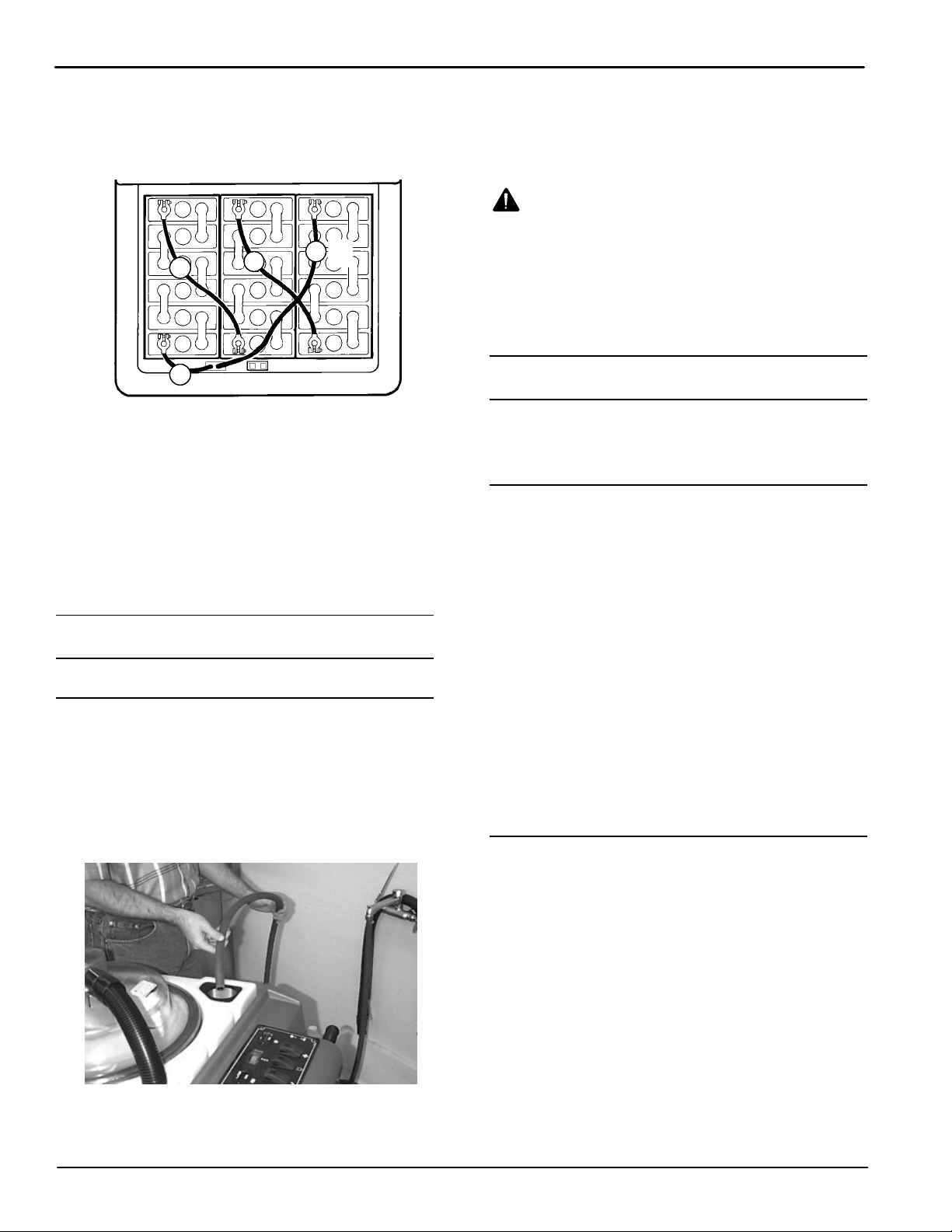
4. Connect cables to battery posts in numerical order
as labeled (RED to POSITIVE & BLACK to
NEGATIVE). Cover post with rubber boot
(Figure 3).
BLK
4
1
RED (+)
5. Double check cable connections before closing up
battery compartment.
6. Replace hood and reset the main circuit breaker
button.
7. Turn main power switch on, and check battery
meter charge level to ensure batteries are fully
charged. If batteries need charging, see
BATTERY CHARGING.
3
2
FIG. 3
(–)
MACHINE SETUP
3. Add recommended cleaning chemical. Use proper
dilution ratio instructions on bottle.
FOR SAFETY: When using machine, follow mixing
and handling instructions on chemical containers.
WARNING: Flammable materials can cause
an explosion or fire. Do not use flammable
materials in tank(s).
ATTENTION: Use only recommended cleaning
chemicals, DO NOT use substitutes. Consult an
authorized distributor to assist you with the
recommended cleaning chemicals.
MACHINE OPERATION
FOR SAFETY: Do not operate machine unless
operator manual is read and understood.
PRE–OPERATION CHECKS
1. Vacuum floor and remove debris.
2. Check battery meter charge level; machine
should be fully charged prior to using. Do not
operate machine if batteries are discharged below
half (See BATTERY CHARGING).
3. Check that recovery tank standpipe screen is in
place.
FILLING SOLUTION TANK
1. Transport machine to filling station (See
MACHINE OPERATION).
2. Fill solution tank with 113.5 L (30 gal) of clean
water at fill port, 60° C (140° F) maximum
temperature. Use gallon markers on side of tank
to indicate fill level (Figure 4).
FIG. 4
NOTE: If filling with a bucket be certain that bucket is
clean. This will prevent possible solution line clogs.
4. Check that spray bar is installed (See SPRAY
BAR AND SPRAY TIP MAINTENANCE).
5. Check that inline strainer filter is installed (See
SOLUTION FILTERS MAINTENANCE).
6. Inspect spray tips for proper spray pattern (See
SPRAY BAR AND SPRAY TIP MAINTENANCE).
TRANSPORTING MACHINE
Operating machine without using cleaning functions.
1. Raise brush lift lever and engage lock block.
2. Activate main power switch.
3. Press drive switch towards transport mode symbol
(Figure 5).
6
Concorde HP Plus (01–00)
Page 7
OPERATION
Home
Find...
Go To..
FIG. 5
4. Turn speed control knob to slowest setting.
(Figure 6).
FIG. 6
5. Rotate control grips completely forward and slowly
turn speed control knob to desired travel speed
(Figure 7).
FIG. 8
7. To stop machine, release control grips and turn off
machine.
CLEANING WITH MACHINE
1. Lower brush lift lever and engage lock block
(Figure 9).
FIG. 9
2. Activate main power, pump and vacuum switches.
3. Press drive switch towards clean mode symbol
(Figure 10).
FIG. 7
ATTENTION: For first time users, operate at a
slower speed until maneuvering becomes easy.
6. To transport machine in reverse, simply pull
reverse drive trigger (Figure 8).
Concorde HP Plus (01–00)
FIG. 10
7
Page 8
OPERATION
Home
Find...
Go To..
4. Select cleaning method by pressing restorative/
interim cleaning switch (Figure 11).
FIG. 11
Restorative Cleaning Method: The
machine operates at a slower set speed to restore
heavily soiled carpet areas. The restorative
cleaning method must be performed on a regular
basis in order for the interim cleaning method to
be effective.
FIG. 13
7. To operate machine in reverse, raise brush lever
and pull reverse drive trigger (Figure 14).
Interim Cleaning Method: Machine
operates at faster set speed for routine light
cleaning. The interim cleaning method will be
ineffective if the restorative cleaning method is not
performed on a regular basis.
5. Rotate control grips completely forward to begin
cleaning (Figure 12).
WARNING: Flammable materials or reactive
metals can cause explosion or fire. Do not pick
up.
NOTE: Machine travel speed for the cleaning modes
are set speeds.
FIG. 14
8. To stop cleaning, release control grips. Raise
brush lever and turn off machine.
9. After cleaning carpet, allow 3 to 4 hours for carpet
to dry. Use air movers to reduce drying time.
WHILE OPERATING MACHINE
WARNING: Flammable materials or reactive
metals can cause explosion or fire. Do not pick
up.
1. Periodically check for foam buildup in recovery
tank
(look through clear dome)
buildup begins to develop, pour a recommended
foam control solution into recovery tank.
ATTENTION: Do not allow foam or water beyond
“FULL LINE” label, located on standpipe, vacuum
motor damage will result. Vacuum motor damage
due to foam or water is not covered by warranty.
. If excessive foam
6. View brush pressure meter while operating. Meter
FIG. 12
should read center of green zone (Figure 13). If
brush height adjustment is required, see
ADJUSTING BRUSH HEIGHT.
8
2. Overlap each pass by about 51 mm (2 in).
3. Keep machine within 152–203 mm (6–8 in) of
baseboard.
4. When turning, it may be necessary to turn pump
switch off and raise brush lift lever.
Concorde HP Plus (01–00)
Page 9
5. Before reaching end of cleaning path, turn pump
Home
Find...
Go To..
switch off and continue to drive machine forward
to extract solution.
6. Drain recovery tank when recovered water
reaches “FULL LINE” label, located on standpipe
in recovery tank (See DRAINING TANKS).
7. Observe gallon marker for remaining cleaning
solution.
8. Periodically check battery meter discharge level.
Recharge batteries when discharged below half.
9. When solution tank runs dry, turn off pump and
vacuum switches, raise brush and transport
machine to draining area (See DRAINING
TANKS).
10. If cleaning path leaves streaks, spray tip cleaning
is required (See SPRAY BAR AND SPRAY TIP
MAINTENANCE).
11. If machine is left unattended, turn off machine and
pull out main circuit breaker button.
FOR SAFETY: Before leaving or servicing
machine, stop on level surface, turn off machine
and pull out main circuit breaker button.
OPERATION
ADJUSTING BRUSH HEIGHT
1. Turn all switches off.
FOR SAFETY: Before leaving or servicing
machine, stop on level surface, turn off machine
and pull out main circuit breaker button.
2. Disengage brush lift lever from lock block
(Figure 16).
FIG. 16
3. Locate adjustment knobs on adjustment shaft and
loosen bottom knob (Figure 17).
CIRCUIT BREAKER PANEL
The machine is equipped with (3) resetable circuit
breakers to protect machine from damage, (labeled as
brush, main and drive). They stop current flow when
circuit overload occurs. Once a circuit breaker has
tripped, determine problem, let motor cool down and
manually reset breaker by pressing circuit breaker
button. The vacuum motors are thermally protected
and will automatically shut–off when an overload
occurs. The main and drive circuit breakers are
designed so you can stop current flow by manually
pulling out circuit breaker buttons. Pull out the main
circuit breaker button when servicing machine or when
machine is left unattended. Circuit breaker buttons are
located at rear of machine as shown (Figure 15).
FIG. 17
4. Turn upper knob clockwise to lower brush and
counterclockwise to raise.
5. Tighten down bottom knob after adjusting.
Concorde HP Plus (01–00)
FIG. 15
9
Page 10
OPERATION
Home
Find...
Go To..
ACCESSORY TOOL SETUP AND OPERATION (OPTION)
Machine is equipped with accessory tool hookups. The
floor tool accessory enables you to reach areas that
machine is unable to, such as alcoves and corners.
NOTE: Vacuum area before cleaning.
1. Turn main power switch off.
2. Disconnect vacuum hose from recovery dome and
replace with accessory vacuum hose (Figure 18).
FIG. 18
3. Connect solution hose to accessory coupler at
rear of machine (Figure 19).
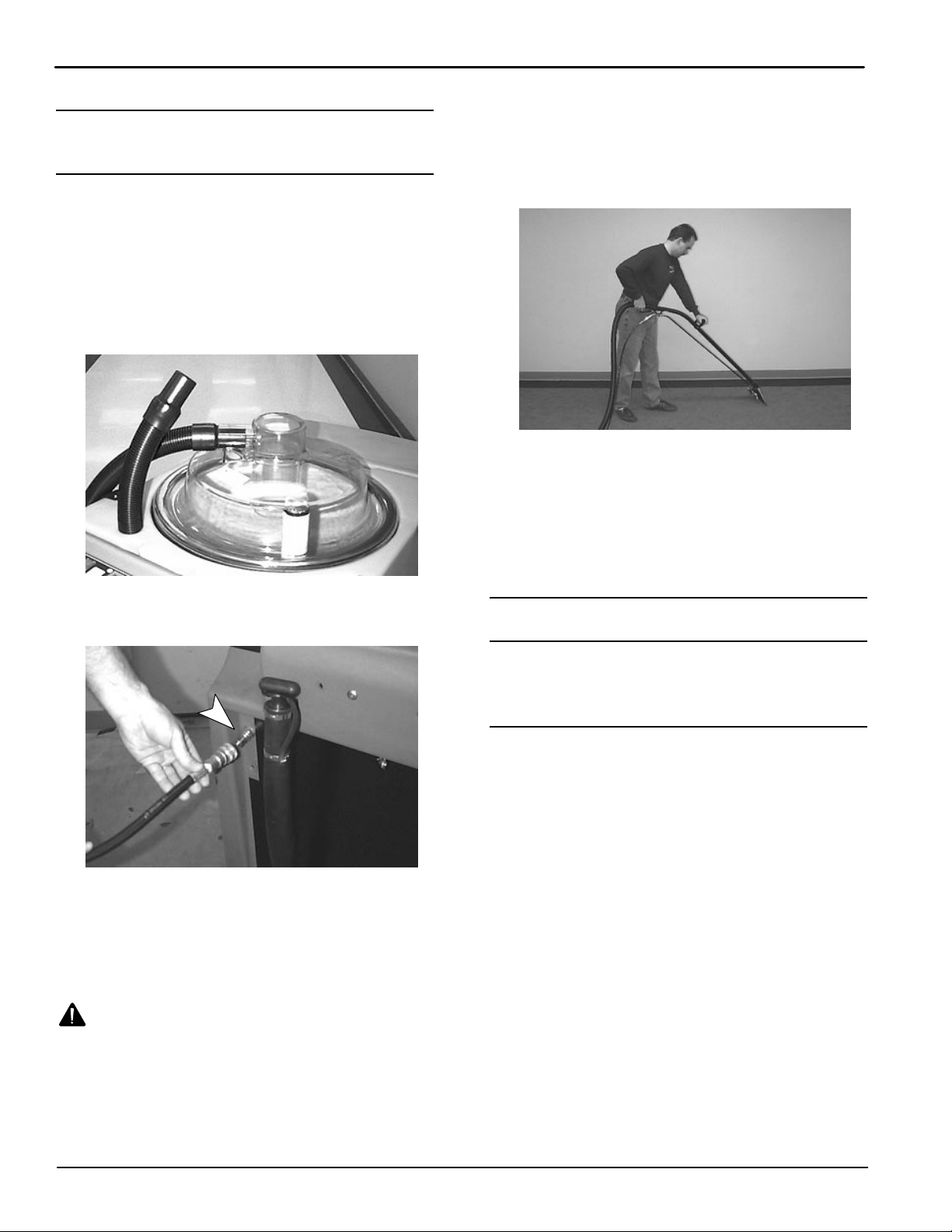
9. Place floor tool so bottom of stainless shoes are
parallel to floor. Squeeze trigger and apply
downward pressure on floor tool head and slowly
pull tool backwards using both hands. Release
trigger 152 mm (6 in) from end of stroke
(Figure 20).
FIG. 20
10. Push floor tool forward over same path with trigger
released when returning for next stroke. Continue
this pull and push method with a 51 to 102 mm (2
to 4 in) overlap of each stroke.
NOTE: For heavily soiled areas, repeat stroke or
change angle of stroke.
DRAINING TANKS
FIG. 19
4. Connect hoses to accessory tool.
5. Raise brush lift lever and engage lock block.
6. Turn main power, pump and vacuum switches on.
7. Operate accessory tool as normal.
WARNING: Flammable materials or reactive
metals can cause explosion or fire. Do not pick
up.
8. For floor tool cleaning: Begin cleaning at top of
area and work backwards toward machine.
When finished cleaning, the recovery and solution
tanks should be drained and cleaned.
DRAINING RECOVERY TANK
1. Transport machine to nearest floor sink or drain.
2. Turn all switches off.
3. Remove drain hose from holder, position hose
over floor drain and twist off drain hose plug to
drain (Figure 21).
NOTE: If using a bucket to drain machine, use a
separate bucket for filling solution tank. This will
prevent possible solution line clogs.
10
Concorde HP Plus (07–99)
Page 11
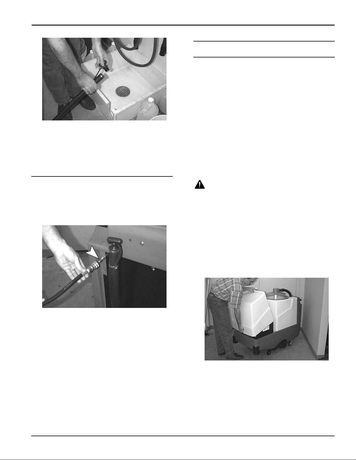
FIG. 21
Home
Find...
Go To..
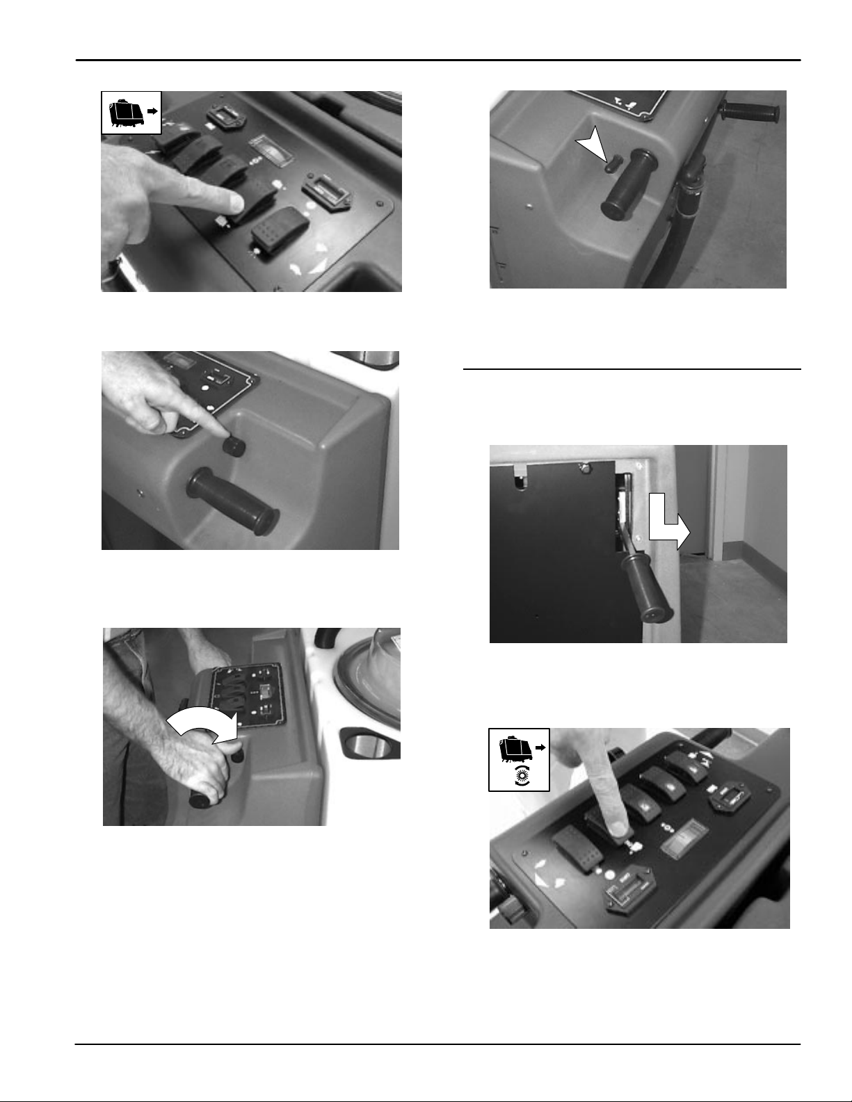
4. Remove recovery tank dome and use a hose to
rinse out recovery tank. Be careful not to spray
water into standpipe screen.
5. Replace drain hose plug tightly when tank is
empty.
OPERATION
BATTERY CHARGING
The following charging instructions are intended
for chargers supplied with machine. Use a battery
charger with the following specifications to
prevent battery damage.
CHARGER SPECIFICATIONS:
OUTPUT VOLTAGE – 36 VOLTS
OUTPUT CURRENT – 25 AMPS
AUTOMATIC SHUT–OFF CIRCUIT
FOR LEAD ACID DEEP CYCLE BATTERY CHARGING
NOTE: Recharge batteries ONLY after a total of 30
minutes or more. This will prolong battery life. Never
leave batteries discharged for lengthy periods.
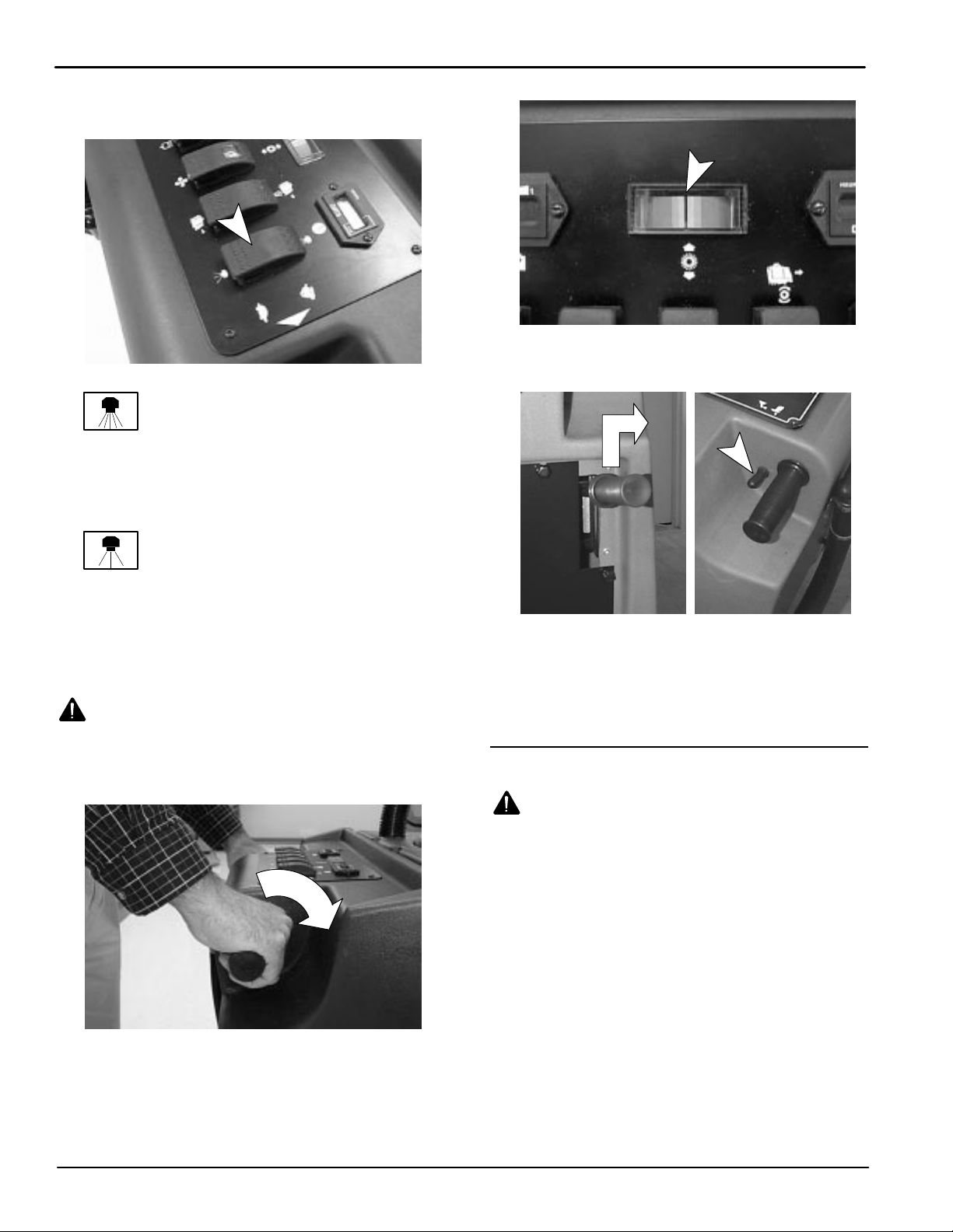
DRAINING SOLUTION TANK
To drain unused solution from solution tank, pumpout
hose is required (Supplied with machine).
1. Connect pumpout hose to accessory tool coupler
at rear of machine (Figure 22).
FIG. 22
2. Hold hose over floor sink or remove recovery
tank dome and direct hose into tank.
3. Activate main power and pump switch.
WARNING: Batteries emit hydrogen gas.
Explosion or fire can result. Keep sparks and
open flame away. Keep battery compartment open
when charging.
FOR SAFETY: When servicing machine, wear
protective gloves when handling batteries and
battery cables. Avoid contact with battery acid.
1. Transport machine to a well–ventilated area for
charging.
2. Turn main power switch off.
3. Remove battery compartment hood to access
batteries (Figure 23).
Concorde HP Plus (01–00)
FIG. 23
11
Page 12
OPERATION
Home
Find...
Go To..
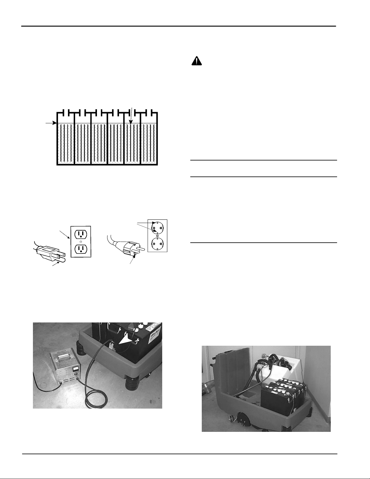
4. Check water level (A) in each battery cell. Do not
charge batteries unless water is slightly covering
battery plates (B). If needed, add just enough
distilled water to slightly cover plates. DO NOT
overfill. Batteries can overflow during charging due
to expansion. Replace cell caps before charging
(Figure 24).
B
A
FIG. 24
5. With charger disconnected from machine, plug
charger’s power cord into a grounded wall outlet
(Figure 25).
Grounded
3 Hole Outlet
Grounded Outlet
NOTE: The machine will become inoperable once
charger is connected.
WARNING: Batteries emit hydrogen gas.
Explosion or fire can result. Keep sparks and
open flame away. Keep battery compartment open
when charging.
8. When disconnecting charger, always unplug
charger from wall outlet first.
9. After charging, recheck battery fluid level. If
needed, add distilled water to bring level of fluid to
bottom of sight tubes. Be certain to replace cell
caps securely and to wipe off the top of batteries
with a clean cloth.
10. Replace battery compartment hood.
MACHINE MAINTENANCE
To keep machine in good working condition, simply
follow daily, weekly and monthly maintenance
procedures.
FOR SAFETY: Before leaving or servicing
machine, stop on level surface and turn off
machine.
Grounding
Ground Pin
(120V) (230V)
6. Connect battery charger into machine as shown
(Figure 26).
7. Charger will automatically begin charging and
automatically shut off when fully charged.
Edge/hole
FIG. 25
FIG. 26
TO ACCESS INTERNAL COMPONENTS
1. Drain recovery and solution tank.
2. Turn main power switch off and disconnect
batteries.
FOR SAFETY: When servicing machine,
disconnect batteries before working on machine.
3. Remove vacuum hoses from vacuum pickup
heads.
4. Remove drain hose from holder and push hose
halfway through U–bracket to allow hose slack .
5. Carefully hinge tank over (Figure 27).
FIG. 27
12
Concorde HP Plus (07–99)
Page 13

OPERATION
Home
Find...
Go To..
HOUR METER
The machine is equipped with an hour meter located
on the control console. Use hour meter to determine
recommended maintenance procedures and to record
service history (Figure 28).
FIG. 28
DAILY MAINTENANCE
(Every 4 Hours of Use)
1. Recharge batteries (See BATTERY CHARGING).
NOTE: Recharge batteries ONLY after a total of 30
minutes or more. This will prolong battery life.
2. Drain and rinse tanks thoroughly.
3. Remove any lint buildup from standpipe screen.
4. Check spray pattern. Pattern should spray evenly
across width of machine (See SPRAY BAR AND
SPRAY TIP MAINTENANCE).
5. Remove lint buildup from splash guard, located
next to brush.
6. Clean machine housing with an all purpose
cleaner and damp cloth.
ATTENTION: Do not power spray or hose off
machine. Electrical component damage due to
water is not covered by warranty.
7. Turn main power switch off, pull out main circuit
breaker button and remove any obstruction
(carpet strands, etc.) from brush.
FOR SAFETY: Before leaving or servicing
machine, stop on level surface, turn off machine
and pull out main circuit breaker button.
8. Remove and clean solution tank fill port strainer.
WEEKLY MAINTENANCE
(Every 20 Hours of Use)
1. Remove and rinse inline strainer filter located
under machine at rear (See SOLUTION FILTER
MAINTENANCE)
2. Check fluid level in battery cells (See BATTERY
MAINTENANCE)
3. Clean battery tops to prevent corrosion.
4. Check for loose or corroded battery cables.
5. Remove and clean spray tips (See SPRAY BAR
AND SPRAY TIP MAINTENANCE).
.
.
MONTHLY MAINTENANCE
(Every 80 Hours of Use)
1. Flush out plumbing system with an acetic acid
solution (See PLUMBING SYSTEM
MAINTENANCE)
2. Check brush belt for wear or excess slack (See
BRUSH BELT MAINTENANCE)
3. Check drive chain for excess slack and lubricate
with a water resistant grease (See DRIVE CHAIN
MAINTENANCE).
4. Lubricate axle and caster grease fittings with a
water resistant grease.
5. Lubricate all linkage pivot points with silicone
spray then coat with a water resistant grease to
maintain a smooth operation.
6. Check machine for water leaks and loose nuts and
bolts.
.
.
QUARTERLY MAINTENANCE
(Every 250 Hours of Use)
1. Check drive and brush motors for carbon brush
wear, replace brushes when worn.
2. Check vacuum motor for carbon brush wear,
replace brushes when worn to a length of 10 mm
(0.38 in) or less.
Contact an Authorized Service Center for motor
maintenance.
Concorde HP Plus (01–00)
13
Page 14

OPERATION
Home
Find...
Go To..
BATTERY MAINTENANCE
WARNING: Batteries emit hydrogen gas.
Explosion or fire can result. Keep sparks and
open flame away. Keep battery compartment open
when charging.
FOR SAFETY: When servicing machine, wear
protective gloves when handling batteries or
battery cables. Avoid contact with battery acid.
1. Always follow proper charging instructions (See
BATTERY CHARGING).
2. Keep battery tops and terminals clean and dry.
To clean batteries:
a. Mix a strong solution of baking soda and
water.
b. Brush solution sparingly over battery tops,
terminal and cable connectors.
NOTE: Do not allow baking soda solution to enter
battery cells.
c. Use a wire brush to clean terminal post and
cable connections.
d. After cleaning, apply a coating of clear battery
post protectant to terminals and cable
connections.
3. Check for loose or worn cables. Replace if worn.
DRIVE CHAIN MAINTENANCE
Inspect drive chain periodically for proper tension.
Chain should flex between 6.35mm (0.25 in ) and
12.7mm (0.50 in) from center. If chain flexes more
than 12.7mm (0.50 in), chain should be tightened.
FOR SAFETY: Before leaving or servicing
machine, stop on level surface, turn off machine
and pull out main circuit breaker button.
To Tighten Chain:
1. Pull out main circuit breaker button to shut off
power to machine (Figure 29).
2. Loosen 4 motor mount bolts, do not remove bolts
(Figure 30).
Tension Bolt
(4) Motor
Mount Bolts
FIG. 30
3. Loosen lock nut on tension bolt (Figure 30).
4. Turn tension bolt to tighten chain. Do not
overtighten.
5. Retighten motor mount bolts and lock nut on
tension bolt.
6. Lubricate chain with a water resistant oil.
7. Reset main circuit breaker button.
BRUSH BELT MAINTENANCE
Brush belt can wear prematurely if belt tension is not
correct. If belt flexes more than 12.7 mm (0.50 in) from
center, belt should be tightened.
FOR SAFETY: Before leaving or servicing
machine, stop on level surface, turn off machine
and pull out main circuit breaker button.
To Tighten Or Replace Brush Belt:
1. Pull out main circuit breaker button to shut off
power to machine (Figure 29).
2. Remove belt guard, two screws (Figure 31).
(4) Motor
Mount Bolts
14
FIG. 31
3. Remove any debris in pulley assembly.
4. Inspect belt for wear and for proper tension.
FIG. 29
Concorde HP Plus (01–00)
Page 15

5. To tighten or replace belt, loosen 4 brush motor
Home
Find...
Go To..
mount bolts. If worn, replace belt (Figure 31).
6. To tighten belt, pull back on motor until belt
becomes tight, retighten mounting bolts.
7. Replace brush guard and reset main circuit
breaker button.
PLUMBING SYSTEM MAINTENANCE
FOR SAFETY: Before leaving or servicing
machine, stop on level surface and turn off
machine.
Each month or every 80 hours of operation flush out
plumbing system with an acetic acid solution. This will
prevent plumbing system from clogging and reduce
the risk of pump failure. Also check plumbing system
for any leaks; repair if necessary. Solution pump does
not require lubrication.
1. Pour 750ml (24 oz) of acetic acid solution with
11.3 L (3 gal) of hot water, 60° C (140° F), into
solution tank.
FOR SAFETY: When using machine, follow mixing
and handling instructions on chemical containers.
2. Transport machine over a floor drain.
3. Pull out drive motor circuit breaker button to shut
off power to drive motor.
4. Activate main power and pump switches.
5. Press drive switch towards clean mode symbol.
6. Rotate control grips completely forward and hold
for 2 to 3 minutes.
7. Turn main power off and let machine sit overnight
to allow acetic acid to break down alkaline buildup.
8. Next day, over a floor drain, disperse remaining
solution.
9. Fill solution tank with 11.3 L (3 gal) of clean water
and operate machine to flush out excess acetic
acid solution.
10. Reset drive motor breaker button.
OPERATION
FIG. 32
3. Remove screens from bowl and clean.
4. When replacing filter, be certain clear bowl is
threaded securely.
SOLUTION TANK STRAINER
1. Remove solution tank fill port strainer from inside
fill port (Figure 33).
FIG. 33
2. Rinse filter and remove any debris.
STANDPIPE SCREEN
1. Remove recovery tank dome.
2. Remove screen from standpipe and rinse off,
replace screen securely. (Figure 34).
SOLUTION FILTER MAINTENANCE
Remove the following solution filters and clean them
as needed. Replace filters if damaged.
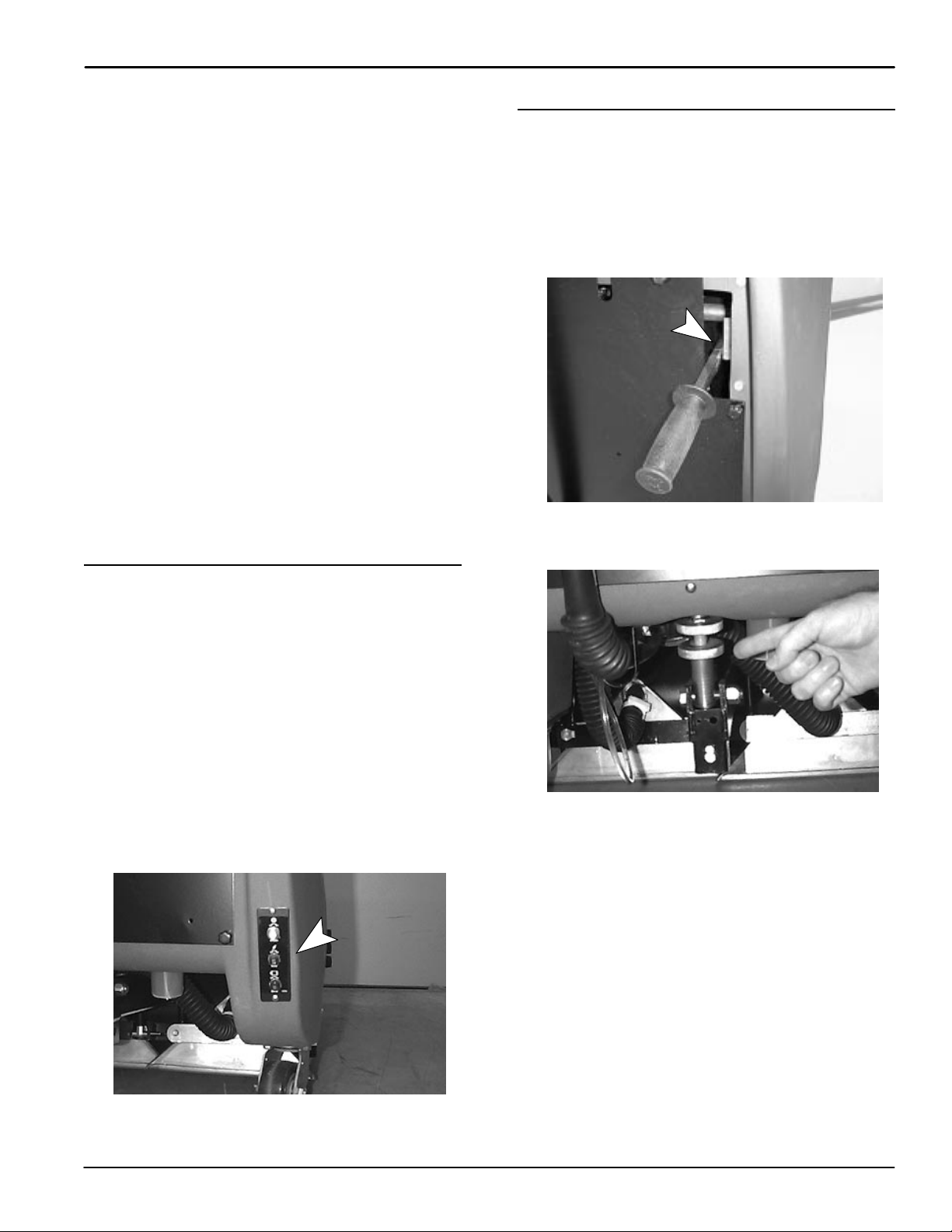
INLINE STRAINER FILTER
1. Pump solution tank dry to prevent water from
spilling when removing filter.
2. Unscrew and remove inline strainer filter (clear
bowl). Filter is located underneath at rear of
machine (Figure 32).
Concorde HP Plus (01–00)
FIG. 34
15
Page 16

OPERATION
Home
Find...
Go To..
SPRAY BAR AND SPRAY TIP MAINTENANCE
The spray bar can easily be removed and replaced
with a spare spray bar when spray tips require
maintenance.
TO REPLACE SPRAY BAR:
1. Turn main power switch off.
2. From operator’s right side of machine, locate
spray bar under machine.
3. To remove spray bar, shift spray bar to operator’s
left side of machine and pull down (Figure 35).
TRANSPORTING MACHINE
When transporting machine by use of trailer or truck,
be certain to follow tie–down procedures below:
FOR SAFETY: When using machine, go slow on
inclines and slippery surfaces.
1. Raise brush.
2. Load machine using a recommended loading
ramp.
3. Position front of machine up against front of trailer
or truck. Once machine is positioned, lower brush.
4. Place a block behind the drive wheel and the rear
casters.
5. Place tie–down straps over top of machine and
secure straps to floor. It may be necessary to
install tie–down brackets to the floor of your trailer
or truck.
STORING MACHINE
FIG. 35
4. Disconnect coupler at spray bar top.
5. Install spare spray bar, be certain to position spray
bar “FRONT” label facing forward.
TO CLEAN SPRAY TIPS:
1. Remove clogged spray tips from spray bar. Take
note of spray tip position before removing.
2. Pour 4 oz. of acetic acid into a small container.
3. Completely submerge spray tips and let soak for
up to six hours. Agitate spray tips occasionally.
4. After soaking spray tips, use small brush to
remove excess alkaline and rinse thoroughly.
ATTENTION: DO NOT use pointed objects such as
pins and paper clips to unplug spray tips. This
will damage spray tips, causing improper spray
pattern and water flow through tips.
5. Replace spray tips in spray bar and keep on hand
for spare.
NOTE: If spray tips are damaged, replace spray tips.
Be certain to use same spray tip size and type.
Improper spray tips will affect cleaning performance.
1. Before storing machine, be certain to flush tanks
and drain machine of all water.
2. Store machine in a dry area with the brush in the
raised position.
3. Remove recovery tank dome to promote air
circulation.
ATTENTION: If storing machine in freezing
temperatures, be certain to drain machine of all
water. Damage due to freezing temperatures is not
covered by warranty.
16
Concorde HP Plus (01–00)
Page 17

OPERATION
Home
Find...
Go To..
TROUBLE SHOOTING
PROBLEM CAUSE SOLUTION
Machine does not operate. Main circuit breaker button pulled out. Push in main circuit breaker button.
Faulty main circuit breaker. Contact Service Center.
Faulty main power switch. Contact Service Center.
Charger connected to machine. Unplug charger from machine after com-
plete charge cycle.
Faulty master solenoid. Contact Service Center.
Loose battery connection. Check battery connections.
Loose connections at solenoid panel. Contact Service Center.
Batteries need charging. See BATTERY CHARGING.
Faulty battery(s). Replace battery(s).
Battery connection is improper. See BATTERY INSTALLATION.
Vacuum motor does not
operate.
Vacuum recovery is poor. Vacuum pickup heads are not sealed to
Uneven or no spray. Inline strainer filter is plugged. Drain solution tank and remove filter and
Brush motor does not operate. Brush circuit breaker is tripped. Remove any obstruction in brush and
Vacuum thermal overload tripped. Check air flow for obstructions, wait 20
minutes for motor to cool.
Faulty vacuum switch. Contact Service Center.
Loose wiring. Contact Service Center.
Faulty vacuum motor. Contact Service Center.
Carbon brushes worn. Contact Service Center.
Lock vacuum head lift lever under lock
carpet.
Carpet fibers are restricting air flow
through vacuum shoes or standpipe
screen.
Vacuum hose(s) disconnected from vacuum shoes or recovery dome.
Drain hose plug is not fully inserted into
drain hose.
Loose or failed gasket(s). Contact Service Center.
Spray tips are plugged. Clean plugged spray tips.
Faulty solution pump. Contact Service Center.
Pump switch is off. Turn on pump switch.
Control grips not rotated. Control grips must be rotated to activate
Loose wiring. Contact Service Center.
Faulty motor. Contact Service Center.
Loose or broken belt. Replace or contact Service Center.
Carbon brushes worn. Contact Service Center.
Faulty solenoid. Contact Service Center.
block.
Remove lint from vacuum shoes (use a
coat hanger) or from standpipe screen
in recovery tank.
Connect hoses or call for service.
Insert drain hose plug and tighten.
clean. Located under machine at rear.
spray.
reset breaker.
Concorde HP Plus (01–00)
17
Page 18

OPERATION
Home
Find...
Go To..
TROUBLE SHOOTING –continued
PROBLEM CAUSE SOLUTION
Drive motor does not run. Drive motor circuit breaker is tripped. Reset drive circuit breaker.
Loose drive chain. Adjust or call for service.
Faulty wiring or drive switch. Contact Service Center.
Faulty motor. Contact Service Center.
Main circuit breaker has tripped or is
pulled out.
Faulty speed control circuit board or
connection.
Faulty solenoid. Contact Service Center.
Worn carbon brushes. Contact Service Center.
Faulty potentiometer or speed control
board.
Batteries will not take a
charge.
Short run time. Batteries not fully charged. Charge batteries.
Charger plug not connected correctly. Connect plug correctly.
Low battery fluid level. See Battery Maintenance Section.
Charge cycle not completed. Let charge until fully charged.
Faulty charger. Replace charger.
Bad battery cell(s). Replace battery.
Batteries need maintenance. See BATTERY MAINTENANCE.
Faulty charger. Replace battery charger.
Determine cause and reset breaker.
Contact Service Center.
Contact Service Center.
18
Concorde HP Plus (01–00)
Page 19

SPECIFICATIONS
Home
Find...
Go To..
OPERATION
MODEL
LENGTH 1370 mm (54 in)
WIDTH 710 mm (28 in)
HEIGHT 1190 mm (47 in)
WEIGHT – WITH BATTERIES 306Kg (675 lbs)
BATTERIES 3–12V Deep Cycle Lead Acid, 215Amp hours
RUN TIME AT FULL CHARGE 3.5 Hours
SOLUTION TANK CAPACITY 121L (32 Gal)
INTERIM CLEANING RATE 1115 m2 (12,000 sq. ft.) per hour
RESTORATIVE CLEANING RATE 557 m2 (6,000 sq. ft.) per hour
TRANSPORT MODE SPEED VARIABLE
CLEANING PATH WIDTH 610 mm (24 in)
DRIVE MOTOR .75 h.p., 0–1200 rpm, 36V, 17A
BRUSH MOTOR .5 h.p., 1200 rpm, 36V, 13A,
V ACUUM MOTOR 2 – .9 h.p., 3–stage 5.7”, 36V, 18.75A, 612W, 152cfm
SOLUTION PUMP 100psi, 36V
SEALED WATER LIFT 3680 mm (145 in)
DECIBEL RATING AT OPERATOR’S EAR, INDOORS ON CARPET
CONCORDE HP PLUS
76dB(A)
Concorde HP Plus (01–00)
19
Page 20

PARTS LIST
Home
Find...
Go To..
UPPER HOUSING GROUP
5
4
3
8
6
6a
2
7
1
4
11
10
9
12
13
14
15
27
26
26
21
19
28
24
29
24
30
30
21
31
22
24
24
25
24
25
23
32
31
16
15
17
20
19
18
24
30
33
20
Concorde HP Plus (09–98)
Page 21

UPPER HOUSING GROUP
Home
Find...
Go To..
REF PART # DESCRIPTION QTY.
608408 TANK, SOLUTION (GREEN) 1
1
2 180610 SCREEN, SOLUTION TANK 1
3 180612 SCREEN, STANDPIPE 1
4 150303 GASKET, INLET FLANGE 2
5 603094 FITTING, INLET FLANGE W/FLATS 1
6 701225 ASM. STANDPIPE 1
6a 606088 NIPPLE, 11/2, STANDPIPE 1
7 101714 GASKET, WASTE AIR CHAMBER 1
608410 TANK, RECOVERY (GREEN) 1
8
9 240178.BK TUBE, INLET 1
10 140308 CLAMP, HOSE 2
11 160846 HOSE, 1 1/2 X 10 1/4 1
12 160430 CUFF, HOSE 1 1/2 X 1 1/2 1
13 100111 DOME, VACUUM 1
14 100032 GASKET, DOME & TANK 1
15 140322 CLAMP, VAC HOSE PICKUP TOOL 4
16 160456 HOSE, PICKUP TOOL 16" 2
17 608414 COVER, HOOD (GREEN) 1
PARTS LIST
REF PART # DESCRIPTION QTY.
611071000 MOTOR, VAC 5.7/35TG 36V W/SNOUT 1
18
190162 BRUSH, CARBON 2
19 0174..10 SEAT, NEOPRENE MOTOR 2
20 230957 PLATE, VAC MOUNT 1
21 140238 STUD, FULL THRD 1/4-20 X 5 6
22 140208 SCREW, 1//4-20 X 1 2
23 101807 PLATE, CONNECTOR 1
24 140000 WASHER, FLAT 1/4 12
25 140524 NUT, KEP 1/4-20 2
26 140308 CLAMP, HOSE 1-5/16 - 2 1/4 2
27 160631 HOSE, 1 1/2 X 16 1
130413 MOTOR, VAC 5.7, 3 STG 1
28
190162 BRUSH, CARBON (2/PK) 2
29 210240 NUT, FLANGED 1
30 140501 NUT, NYLOC 4
31 140259 SCREW, 1/4-20X5/8 2
32 140016 WASHER, LOCK 2
33 600009 MUFFLER, EXHAUST 1
DECALS LIST
REF PART # DESCRIPTION QTY.
N/S 608415 DECAL, CONCORDE HP PLUS 2
N/S 608188 DECAL, "NOBLES" 1
N/S 602637 DECAL, BATTERY CHARGE 1
N/S 120246 DECAL, CAUTION DO NOT ......." 1
N/S 120247 DECAL, FULL LINE 1
N/S= NOT SHOWN
Concorde HP Plus (01–00)
21
Page 22

PARTS LIST
Home
Find...
Go To..
MAIN CHASSIS GROUP
21
21
22
33
3
49
50
40
44
1
6
53
7
8
9
10
20
14
15
19
13
11
12
17
16
18
52
51
5
4
2
48
46
45
55
47
22
35
36
37
39
34
38
32
42
43
30
23
28
29
27
24
26
25
54
Concorde HP Plus (03–96)
31
9
41
Page 23

MAIN CHASSIS GROUP
Home
Find...
Go To..
REF PART # DESCRIPTION QTY.
608412 CHASSIS (GREEN) 1
1
231023.BK PANEL, REAR 1
2
120649 DECAL, "WARNING" (NOT SHOWN) 1
3 240204 KNOB 5
4 140831 SCREW, 6-32x5/8 2
5 230696.BK BRACKET, DRAIN HOSE 2
160231 TUBING, 1/8ID CLR VYL (4.6 FT) 1
6
120243 DECAL, GALLON MARKER (NOT SHOWN) 1
7 140553 SCREW, 1/4-20 9
8 140000 WASHER, FLAT 1/4 9
9 140016 WASHER, LOCK 1/4 9
10 140440 HINGE, SOLUTION TANK 1
11 600437 SWITCH, LIMIT 1
12 200301012 WASHER, FLAT 2
13 140539 NUT, KEP 6-32 2
14 140852 SCREW, SHT MTL #12 X 3/4 2
15 231040.BK PLATE, PLUG MOUNT 1
16 200070266 SCREW, PAN HD M03 X 16MM 2
17 579211 NUT, LOCK M03 2
18 140829 SCREW, 6-32 x 1 2
19 130155 CONNECTOR, GRAY 50A 1
20 140026 WASHER, FLAT 2
21 130367 CABLE, BATTERY 15" BLK 6 GA 2
22 600394 BATTERY, 12V, 215AH 3
23 103026 WHEEL, BUMPER 6
24 140008 WASHER, FLAT 2
230246.BK BRACKET, BUMPER WHEEL (LEFT) 1
25
230247.BK BRACKET, BUMPER WHEEL (RIGHT) 1
26 140562 SCREW, 1/2 X 6 1/2 2
27 140563 BOLT, LAG 5/16 X 1 4
28 230832 ELBOW, 90° 1 1/4H X 1 1/4M 1
PARTS LIST
REF PART # DESCRIPTION QTY.
29 230833 ADAPTER, PVC 1 1/4F X 1 1/2M 1
30 603094 INLET FLANGE, W/FLATS 1
31 140307 CLAMP, 1 9/16 1
32 160415 HOSE DRAIN 1
∇33 701061 ASM, PLUG 1
34 230831 KNOB, DRAIN HOSE 1
35 230882 STRAP, PLUG 1
36 140056 WASHER, FENDER 1
37 140955 PLUG, DRAIN HOSE 1
38 140921 SLEEVE, DRAIN HOSE 1
39 140072 CLAMP, EAR 1-9/16" 2
40 140025 WASHER, FLAT 8
41 140823 SCREW, 10-24 X 5/8 2
42 230109.BK BRACKET, HOSE SUPPORT 1
43 140552 NUT, NYLOC 2
44 140201 SCREW, 3/8-16 X 3/4 8
45 103002 CASTER, 4" SWIVEL 2
46 130755 BREAKER, CIRCUIT SWITCH 10 AMP 1
47 130739 BREAKER, CIRCUIT MASTER 60 AMP 1
48 130737 BREAKER, CIRCUIT BRUSH 10 AMP 1
49 140887 SCREW, 10-24X3/8 2
231058.BK PLATE, CIRCUIT 1
50
120245 DECAL, CIRCUIT BREAKER (NOT SHOWN) 1
51 600969 CABLE, RED 1
52 600970 CABLE, BLACK 1
53 100709 BOX, BATTERY 1
469760868 CHARGER, BATTERY (120V) 1
54
600599 CHARGER, BATTERY (230V) 1
55 140539 NUT, KEP 2
∇ ASSEMBLY
INCLUDED IN ASSEMBLY
Concorde HP Plus (01–00)
23
Page 24

PARTS LIST
Home
Find...
Go To..
CONTROL CONSOLE GROUP
6
7
2
8
1
4
3
23
25
11
5
9
12
10
13
24
22
21
24
20
18
16
18
14
17
15
19
Concorde HP Plus (01–00)
Page 25

CONTROL CONSOLE GROUP
Home
Find...
Go To..
602919
REF PART # DESCRIPTION QTY.
1 609177 PLATE, CONTROL CONSOLE 1
2 630143 METER, HOUR 1
3 130046 METER, BRUSH PRESSURE 1
4 140539 NUT, 6-32 KEPS 4
5 130779 METER, BATTERY 1
6 130772 SWITCH, DPST ROCKER 2
7 601107 SWITCH, LIGHTED ROCKER 3
8 140810 SCREW, 6-32X3/8 4
9 130775 POTENTIOMETER, LOCKABLE 4
10 130776 POTENTIOMETER 1
11 606550 KNOB, SPEED CONTROL 3
12 601108 SWITCH, TOGGLE 1
13 130753 BOOT, SWITCH 1
PARTS LIST
REF PART # DESCRIPTION QTY.
14 601001 TUBE, HANDLE 1
15 200823 GRIP, HANDLE 2
16 601127 BRACKET, SWITCH 1
17 140885 SCREW 1/4-20X1/2 2
18 140019 WASHER, EXT. LOCK TOOTH #6 2
19 140830 SCREW, 6-32X1-3/4 2
20 601104 SCREW, 5/16-18X3 HXHDCP 1
21 130729 SWITCH, ROLL THROTTLE 2
22 140539 NUT, KEP 2
23 601118 SPRING 1
24 140823 SCREW 1
25 140519 NUT 1
Concorde HP Plus (01–00)
25
Page 26

PARTS LIST
Home
Find...
Go To..
1
DRIVE GROUP
2
27
3
4
12
11
13
10
14
3
4
5
6
25
26
34
7
8
9
15
16
17
35
28
29
30
11
8
7
33
37
28
29
32
1
3
4
30
31
36
26
18
23
20
21
17
24
19
22
Concorde HP Plus (03–96)
Page 27

DRIVE GROUP
Home
Find...
Go To..
REF PART # DESCRIPTION QTY.
1 140202 SCREW, 3/8-16 X 1 4
2 140201 SCREW, 3/8-16 X 3/4 2
3 140028 WASHER, FLAT 3/8 6
4 140008 WASHER, FLAT 1/2 6
5 140015 WASHER, LOCK 5/16 2
6 140559 SCREW, 5/16-18 X 1/2" 2
7 140911 BUSHING, SPACER 5/8 2
8 140204 SCREW, 1/2-13 X 1-1/2 2
9 140545 NUT, 3/8-16 2
10 230645.BK PLATE, SAFETY WHEEL BACK 2
11 140509 NUT 1/2-13 2
12 140943 SCREW, 3/8-16 X 2" 2
13 103007 WHEEL 2
14 140223 SCREW, 5/16-18 X 3/4 3
15 140015 WASHER, LOCK 5/16 9
16 220120.BK RETAINER, WHEEL BEARING 1
17 140124 BEARING, WHEEL 2
18 103027 WHEEL, DRIVE 10" X 4" 1
19 240017 SPROCKET, WHEEL DRIVE 1
PARTS LIST
REF PART # DESCRIPTION QTY.
20 140015 WASHER, LOCK 5 1/6 6
21 140219 SCREW, 5/16-18 x 1 6
22 140202 SCREW, 3/8-16 X 1 4
23 140311.BK BRACKET, WHEEL ASM. 2
24 230205 SHAFT, DRIVE WHEEL 1
25 140525 NUT, 3/8-16 4
26 140017 WASHER, LOCK 3/8 4
130443 MOTOR, DRIVE 1
27
190153 CARBON BRUSH, (4/PK) 4
28 140046 WASHER, FLAT 3/8 3
29 140017 WASHER, LOCK 3/8 3
30 140232 SCREW, 3/8-16 X 1 1/4 4
31 240071 SPROCKET, WHEEL DRIVE 1
32 140859 SCREW, SET 1/4-20 2
33 27076 KEY, STEPPED 1
34 140545 NUT, JAM 3/8-16 1
35 140233 SCREW, 3/8-16 X 1 3/4 1
36 240019 CHAIN, DRIVE 1
37 220107.BK BRACKET, WHEEL ASSEMBLY 1
Concorde HP Plus (09–98)
27
Page 28

PARTS LIST
Home
Find...
Go To..
PLUMBING SYSTEM GROUP
53
54
68
50
57
40
69
51
39
52
48
49
55
56
69
68
67
64
27
5
26
23
9
24
25
5
22
21
1
4
2
3
5
29
27
28
33
5
21
5
B
B
46
45
28
44
34
43
30
41
47
42
37
36
31
32
57
59
38
58
C
17
5
2
3
6
20
7
15
16
5
TO SPRAY
BAR
66
12
35
10
9
A
16
18
19
10
11
10
8
61
C
62
65
64
63
60
6
5
7
A
13
14
28
Concorde HP Plus (03–96)
Page 29

PLUMBING SYSTEM GROUP
Home
Find...
Go To..
REF PART # DESCRIPTION QTY.
1 601142 PUMP, 100PSI 36V 1
2 140000 WASHER, FLAT 1/4 2
3 140881 SCREW, 1/4-20 X1 2
4 150412 ELBOW, 3/8M X 3F/8H 90° 1
5 140310 CLAMP, HOSE 5/16-7/8 15
6 160207 HOSE, LP GRAY (6.66 FT) 1
7 150511 HOSE BARB 1/4F X 3/8 H 1
8 150406 ELBOW, STRT 1/4 X 90° 1
9 150615 NIPPLE, BRASS CLOSE 1/4 1
10 150006 BUSHING, 1/4 X 3/8 3
11 150600 NIPPLE, 1/4 X 2 1
∇12 180615 ASM.,INLINE STRAINER FILTER 1
13 180636 FILTER, SLEEVE 1
14 602000 BOWL, INLINE STRAINER FILTER 1
15 150715 TEE, MALE BRCH 3/8H X 3/8 1
16 160207 HOSE, 3/8 LP GRAY (3 FT) 1
17 140900 SCREW,10-24X3/4 1
18 140916 CLAMP 1
19 140552 NUT, 10-24 1
20 150206 PLUG, 1/4 NPT 1
21 160207 HOSE, 3/8 LP GRAY (.916 FT) 1
22 28303 HOSE BARB 45° 2
23 150706 TEE, 1/4 1
24 140058 WASHER, FLAT 1
25 150933 PLUG, QUICK COUPLER 1
26 150419 ELBOW, 1/4M X 3/8H 90° 1
27 160207 HOSE, 3/8 LP GRAY (.916 FT) 1
28 150525 HOSE BARB 2
29 210046 VALVE, SOLENOID 36V 1
30 600998 BRACKET, SOLENOID 1
31 140023 WASHER 2
32 140801 SCREW 2
33 140837 SCREW 2
34 140018 WASHER, INT LOCK #10 4
35 230978 PLATE, DIVIDER 1
PARTS LIST
REF PART # DESCRIPTION QTY.
36 140887 SCREW, 10-24 X 3/8 4
37 140018 WASHER, INT LOCK #10 4
38 231029.BK PLATE, CONTROL 1
39 140223 SCREW, 5/16-18 X 3/4 5
40 140015 WASHER, SPLIT LOCK 5/16 4
41 600975 BRACKET, REV. SWITCH 1
42 140546 NUT 1
43 140890 SCREW 1
44 130729 SWITCH 1
45 140019 WASHER, EXT. LOCK TOOTH 2
46 210016 SCREW 2
47 140539 NUT 2
48 140221 SCREW 2
49 140015 WASHER 2
50 140237 SCREW, 1/2-13X1" 1
51 150116 BUSHING 1
52 140040 WASHER, POLY 2
53 140868 SCREW 1/4-205/8 2
54 100721 PLATE, LOCK 1
55 220115 BRACKET, SUPPORT 1
56 140501 NUT, LOCK VYL 1/4 2
57 130733 SOLENOID, SPNO 36V 2
58 140011 WASHER 4
59 140890 SCREW 4
60 602827 BOARD, SPEED W/HEAT SINK 1
61 140887 SCREW, 10-24 X 3/8 2
62 140018 WASHER, INT LOCK #10 2
63 140259 SCREW, 1/4-20x5/8 1
64 140016 WASHER 2
65 578427 TERMINAL, STANDOFF 1
66 160207 HOSE, 3/8 LP GRAY (6.583 FT) 1
67 140554 SCREW, 1/4-20 x 3/4 1
68 130423 DIODE, 400V/6.0A 2
69 130125 TERMINAL, RING #10 16-14GA 4
∇ ASSEMBLY
INCLUDED IN ASSEMBLY
Concorde HP Plus (09–98)
29
Page 30

PARTS LIST
Home
Find...
Go To..
BRUSH HEAD GROUP
3
4
2
1
18
5
6
7
8
9
10
11
40
38
57
13
14
58
12
15
53
26
52
59
51
41
29
50
27
36
28
55
35
43
57
34
38
42
40
41
24
33
58
48
32
49
49
47
31
46
45
44
37
54
30
30
19
20
20
22
22
16
56
21
17
19
34
35
36
49
39
23
24 25
Concorde HP Plus (03–96)
Page 31

BRUSH HEAD GROUP
Home
Find...
Go To..
REF PART # DESCRIPTION QTY.
1 200823 GRIP, HAND 1
2 230210 ARM 1
3 140618 PIN, ROLL 1
4 230207 SHAFT, LIFT 1
5 140626 PIN, HITCH 1
6 140608 PIN, CLEVIS 1
7 230309 CLEVIS, LIFT ROD 1
8 231038 ROD, LIFT 1
9 231037 NUT BRUSH ADJUST 1
10 231036 ADAPTER, SPRING 1
11 140516 NUT, LOCK-NYLON 1/2" 1
12 140234 SCREW, 1/4-20X3/4 1
13 140216 SCREW, 5/16-18 X 1 1/2 2
14 140027 WASHER, FLAT 5/16 2
15 140446 SPRING, GAS CYLINDER 2
16 140355 SCREW, 5/16-18 X 2 1/2 2
17 140140 BUSHING 4
18 230979.BK BRACKET, PICKUP TOOL MOUNT 1
19 140204 SCREW, 1/2-13 X 1 1/2 4
20 140040 WASHER 4
21 604958 TOOL, PICKUP W/OFFSET LIPS 2
22 100729 PLATE, PICKUP TOOL 2
23 140003 WASHER, FENDER 1/4 X 1 1
24 140016 WASHER, LOCK 1/4 5
25 140554 SCREW, 1/4-20 X 3/4 1
26 240001 BRUSH, CYLINDER 1
27 140015 WASHER, SPLIT LOCK 5/16 4
28 140221 SCREW, 5/16-18 X 1 1/4 4
29 230206 SHAFT, BRUSH 1
30 140869 SCREW, 10-24 X 1 3/4 2
PARTS LIST
REF PART # DESCRIPTION QTY.
31 140011 WASHER, FLAT 3/16 4
32 140917 SPACER, NYLON .194 X 5/16 X 1 1/2 2
33 140553 SCREW, 1/4-20 X 1/2 4
34 240014 ADAPTER, BRUSH MOUNT 2
35 140123 BEARING, BRUSH 2
36 240015 CAP, BEARING 2
37 240126 BELT, BRUSH DRIVE 1
38 140016 WASHER, LOCK 1/4 4
39 240013 SHEAVE, BRUSH SHAFT 1
40 140554 SCREW, 1/4-20 X 3/4 4
41 140016 WASHER, LOCK 1/4 1
42 230993 PIN, MANIFOLD MOUNT 1
43 578140000 SPRING 1
44 240016 SHEAVE, BRUSH MOTOR 1
45 140208 SCREW, 1/4-20 X 1 4
46 140016 WASHER, LOCK 1/4 4
47 140000 WASHER FLAT 1/4 4
48 130444 MOTOR, BRUSH 1/2 HP 1
49 140628 KEY, 3/16 2
50 230992 PIN, MANIFOLD MOUNT 1
51 140144 BUSHING .375/.380 X.500/.498 2
52 140046 WASHER, 3/8 FLAT 2
53 140202 SCREW, 3/8-16 X 1 2
54 100714 COVER, DRIVE BELT 1
55 230983.BK BRUSH HOUSING 1
56 140911 BUSHING, SPACER 5/8 4
57 140000 WASHER, FLAT 1/4 4
58 140553 SCREW, 1/4-20 X 1/2 2
59 605081 GUARD, SPLASH 1
Concorde HP Plus (03–96)
31
Page 32

PARTS LIST
Home
Find...
Go To..
1
PUMP BREAKDOWN
5
2
3
PUMP BREAKDOWN
REF PART # DESCRIPTION QTY.
190129 KIT, PRESSURE SWITCH 1
1
190172 KIT, PRESSURE SWITCH (VITON) 1
190134 KIT, DIAPHRAGM ONLY 1
190128 KIT, UPPER PUMP HOUSING 1
2
190124 KIT, CHECK VALVE ONLY 1
6
4
REF PART # DESCRIPTION QTY.
3 190171 KIT, VALVE (VITON) 1
4 190131 KIT, SERVICE 1
5 190130 KIT, LOWER PUMP HOUSING 1
6 601142 PUMP, 100 PSI, 36V 1
32
Concorde HP Plus (08–96)
Page 33

PARTS LIST
Home
Find...
Go To..
SPRAY BAR GROUP
4
3
2
1
6
5
7
8
SPRAY BAR GROUP
REF PART # DESCRIPTION QTY.
1 160207 HOSE, 3/8 LP GRAY (6.583 FT) 1
2 140310 CLAMP, HOSE 5/16-7/8 1
3 150516 HOSE BARB 1/4M X 3/8H 1
4 150913 COUPLER, QUICK FEMALE 1
∇ 601143 ASM., SPRAY BAR 1
5 150933 PLUG, QCK COUPLER 1
6 150615 NIPPLE, 1/4 CLOSE 1
10
9
11
REF PART # DESCRIPTION QTY.
7 150430 ELBOW, STRT 1/8M X 1/4F 90° 1
8 230974 SPRAY BAR 6 JET 1
9 150208 PLUG 1/8 2
10 201008 SPRAY NOZZLE 1/8 6
11 603092 TIP, SPRAY QUICK JET 1002 6
N/S 120248 DECAL, FRONT 1
∇ ASSEMBLY
INCLUDED IN ASSEMBLY
N/S= NOT SHOWN
Concorde HP Plus (02–97)
33
Page 34

ELECTRICAL DIAGRAMS
Home
Find...
Go To..
38
23
19
62
11
9
ORG
49
SOLUTION
SOLENOID
BLK
132
4
BATTERY
VOLT
METER
G
R
N
42
38
R
E
D
R
E
D
PUMP
+
–
BLK
6242
+
VAC
MOTOR
38
+
BRUSH
MOTOR
–
DRIVE
MOTOR
VAC
MOTOR
–
56
+
58
57
–
(3) 12 VOLT
BATTERIES
25
26
BLK
RED
BLK
36VDC
YEL
–+
BRUSH
AMMETER
330 ohm
MAIN
SWITCH
30 35
39
YEL
39
R
18
E
D
6
B
L
K
B
L
K
RED
BLK
BLK
+
–
–
+
+
–
BRUSH/SOLUTION
37
19
BRUSH/
PUMP
SWITCH
10
G
R
N
MASTER
SOLENOID
VACUUM
SOLENOID
RED
5
SPEED
CONTROL
BOARD
DRIVE
+
BLK
2
ROLL
SWITCH
BLK
33
GRN
B
L
K
27
BLK
51
RED
BAT.
+–
58
18
26
57
1
CHARGER
PLUG
WIRE DIAGRAM
RED
34
14
330
ohm
15
BLK
42
36
R
E
D
36
53
41
54
25
RED
DRIVE
–
55
BLK
56
BLK
RED
3
+
VACUUM
SWITCH
Y
E
L
41
WHT
BLU
ORG
53
–
ohm
59
R
E
D
R
E
D
2
4
11BLK
BLK
330
10
10 A
DRIVE
C.B.
B
L
K
54
NEGATIVE
STANDOFF
B
L
K
40
T
A
N
16
17
B
L
U
17
12
B
L
U
+–
HOUR
METER
VAC
52
B
L
K
66
P
U
R
RESTOR INTERIM
50 K
WHT
69
21
28
CLEAN
TRAVEL
R
E
D
5
RED
ORG
9
27
INTERIM
70
FWD
BLK
3
GRY
16
10 A
CIRCUIT
BREAKER
RESTOR.
68
B
R
N
REV
ORG
64
REVERSE
SPEED
SETTING
4.7K
ORG
8
RED
7
60 A
MAIN
BREAKER
8
CHARGER PLUG
SWITCH
50 K
28
66
P
U
R
LOCKABLE
BRUSH
HEAD
SWITCH
R
E
D
O
R
G
9
20
9A
O
R
G
9A
B
L
K
72
13
T
A
W
N
H
T
68
B
R
N
50 K
WHT
67
65
RED
72
T
A
N
WHT
63
ROLL
SWITCH
W
H
T
13
WHT
50 K
DASH
MOUNT
FORWARD TRAVEL
SPEED ADJUSTMENT
24
1
34
Concorde HP Plus (01–00)
Page 35

LADDER DIAGRAM
Home
Find...
Go To..
ELECTRICAL DIAGRAMS
CHARGER
PLUG
MAIN
60 A
–1– RED
–7–
RED
–
+
–3– RED
10 A
–4– BLK
(3) 12 VOLT BATTERIES (36VDC)
CHARGER
PLUG
SWITCH
–8–
RED
–10– GRN
–59– RED
–53– RED
–35–
RED
–9–
ORG
–6– RED
BRUSH/
PUMP
SWITCH
SWITCH
–30–
ORG
–36– RED
–30–
RED
–+
MAIN
MASTER SOLENOID
–15– BLK
–34–
RED
–39–
GRN
G
BRUSH/
SOLUTION
ROLL
SWITCH
G
–23– ORG
–49– GRN
–42– RED
–37– YEL
330
–2– BLK
330
PUMP
AMMETER
–19– YEL
–14– BLK
12
34
VOLT
METER
BRUSH
SOLUTION
–11– BLK
–52– BLK
–15– BLK
–62– BLK
–56– BLK–38– RED
–18– BLK
DIRECTION
SWITCH
–13–
WHT
–70–
GRY
–16– BLU
–64–
ORG
REV
FWD
TRAVEL
–72–
TAN
CLEAN
INTERIM
MODE
–68–
BRN
RESTOR
MODE
–66–
PUR
–10– GRN
–5– RED
REVERSE
SPEED
SETTING
50 K
50 K TRAVEL
FORWARD
SPEED
ADJUSTMENT
50 K
50 K
VACUUM
SWITCH
INTERIM
RESTOR
–67–
WHT
–69–
WHT
–63–
WHT
–20–
ORG
–41– YEL
BRUSH
HEAD
SWITCH
DRIVE
ROLL
SWITCH
–65–
G
VACUUM
SOLENOID
–24–
4.7 K
–16–
BLU
–12– BLK
–54– BLK
–59–
–28–
DRIVE
10 A
–25–
RED
ORG
–21–
–17–
–53– RED
VAC
MTR
SPEED
CONTROL
BOARD
BLU
DRIVE
+
330
RED
WHT
+–
BAT.
–40– YEL
VAC
MTR
DRIVE
–
–57– BLK
–58– RED
–55– BLK
HOUR
METER
–52– BLK
–12– BLK
–54– BLK
–26– BLK
DRIVE
MTR
Concorde HP Plus (01–00)
35
Page 36

OPTIONS
Home
Find...
Go To..
127 mm (5 inch) HAND TOOL
1
7
6
3
2
4
REF PART # DESCRIPTION QTY.
200505 TOOL, HAND (COMPLETE) 1
1 200431.BK TOOL, HAND 1
2 150913 COUPLER, QUICK (SER. 60) 1
3 150615 NIPPLE, CLOSE 1
4 200905 TRIGGER, HAND TOOL 1
5 210210 VALVE, FLOW CONTROL 1
6 190600 VALVE PIN & SPRING (NOT SHOWN) 1
SOLUTION AND VACUUM HOSES
1
3
9
8
5
REF PART # DESCRIPTION QTY.
10
11
12
13
7 N/A CAP, VALVE 1
8 150606 NIPPLE, HEX 1/4 1
9 150403 ELBOW, ST 1/4 45° 1
10 200992 BODY, SPRAY 1/4F 1
11 200996 SCREEN, SPRAY NOZZLE 1
12 200965 TIP, SPRAY #8002 1
13 20094 CAP, SPRAY BODY 1
7
5
36
4
4
2
REF PART # DESCRIPTION QTY.
1 160186 HOSE, SOLUTION 25’ 1
2 150913 COUPLER, QUICK SER. 60 1
3 150933 PLUG, QUICK COUPLER 1
4 150615 NIPPLE 2
6
REF PART # DESCRIPTION QTY.
5 160401 HOSE, VACUUM 25 W/ CUFFS 1
6 160430 CUFF, HOSE 1–1/2” 2
7 160451 CONNECTOR, VACUUM HOSE 1–1/2” 1
Concorde HP Plus (03–96)
Page 37

FLOOR TOOL
Home
Find...
Go To..
OPTIONS
4
7
9
8
6
13
14
15
3
5
10
11
12
1
16
17
18
20
21
22
19
2
REF PART # DESCRIPTION QTY.
600048 FLOOR TOOL (COMPLETE) 1
1 200403.BK TOOL, FLOOR 1
2 200939 SHOES, FLOOR TOOL 2
∇3 200927 GRIP, ADJUSTABLE 1
4 200912 FOAM, GRIP 1
5 140259 SCREW, 1/4X3/4 2
6 140834 SCREW, 1/4–20X5/8 2
7 200902 TRIGGER, FLOOR TOOL 1
8 200809 SLEEVE, TRIGGER 1
140605 PIN 1
9
140520 NUT, PUSH (NOT SHOWN) 2
10 210150 VALVE, FLOW CONTROL 1
11 190603 KIT, VALVE PIN & SPRING 1
12 N/A CAP, HEX, VALVE 1
23
24
25
26
REF PART # DESCRIPTION QTY.
13 150403 ELBOW, 1/4–45° 1
14 150615 NIPPLE, CLOSE 1/4 1
15 150913 COUPLER, QUICK SER. 60 1
16 160170 HOSE, 1/4 HP W/ SWEDGE 1
17 150606 NIPPLE, HEX 1/4” 1
18 140058 WASHER 1
∇19 700062 ASM., SPRAY BAR 1
20 150700 CROSS 1
21 150600 NIPPLE 2
22 150401 ELBOW, 90° 1/4FX1/4F 2
23 200993 SPRAY BODY 3
24 200996 SCREEN, SPRAY BODY 3
25 200964 TIP 3
26 200994 CAP, SPRAY BODY 3
∇ Assembly
Included in Assembly
Concorde HP Plus (03–97)
37
 Loading...