

Page 1

About this Manual
We’ve added this manual to the Agilent website in an effort to help you support
your product. This manual is the best copy we could find; it may be incomplete
or contain dated information. If we find a more recent copy in the future, we will
add it to the Agilent website.
Support for Your Product
Agilent no longer sells or supports this product. Our service centers may be able
to perform calibration if no repair parts are needed, but no other support from
Agilent is available. You will find any other available product information on the
Agilent Test & Measurement website,
www.tm.agilent.com.
HP References in this Manual
This manual may contain references to HP or Hewlett-Packard. Please note that
Hewlett-Packard's former test and measurement, semiconductor products and
chemical analysis businesses are now part of Agilent Technologies. We have
made no changes to this manual copy. In other documentation, to reduce
potential confusion, the only change to product numbers and names has been in
the company name prefix: where a product number/name was HP XXXX the
current name/number is now Agilent XXXX. For example, model number
HP8648A is now model number Agilent 8648A.
Page 2

User and
Service Guide
Publication Number 54645-97012
December 1997 (pdf version Nov 1998)
For Safety Information, Warranties, and Regulatory information,
see the pages behind the Index.
© Copyright Hewlett-Packard Company 1996-1997
All Rights Reserved
HP 54645A Oscilloscope and
HP 54645D Mixed-Signal
Oscilloscope
Page 3

The HP 54645A/D at a Glance
Display shows current i nput signals
•
Eighteen (18) channels i n m ai n m ode;
2 scope and 8 timing channels in
delayed mode (HP 54645D)
•
Indicators for peak, av g, or normal
acquisition, time bas e, channel
activity, trigger and acquisition status
•
Softkey labels
•
Measurement results
Channel Controls select, position, and
label inputs
•
Turn channels on or off in di vidually
or in groups of 8 (HP 54645D)
•
Rearrange order of channels to
group related signals ( HP 54645D)
•
Create and display label s to identify
channels ( HP 54645D)
General Co ntrols measure, save and
restore results, and configure the
oscilloscope
•
Make autom atic time and frequency
measurements
•
Use cursors to make ma nual
measurements
•
Save or recall measure m ent
configurat i ons or previous results
•
Autoscale performs simple
one-button s etup of the oscilloscope
Horizontal Controls sel ect sweep speed
and delay parameters
•
Sweep speeds from 5 ns to 50 s/div
(2 ns to 50s/div for HP 54645A)
•
Delay control moves waveform
display to point of interest
•
Delayed mode and delay allow
zooming in to show a port i on of
waveform in detail (spli t screen)
Storage Keys begin and end data
acquisition
•
Run/Stop starts and stops continuous
acquisitions
•
Single perf orm s one acquisition
•
Autostore a ccum ulates and displays
the results of multiple acquisitions
•
Erase clears the current ac qui sition
and all acc um ul ated data
Trigger Key s define what da ta t he
oscilloscope will trigger on
•
Source key (H P 54645A) allows
conventional oscilloscope triggering
•
Edge mode al l ow s triggering on a
positive or negative edge of any
single channel (HP 54 64 5A/D)
•
Pattern mode allows trig geri ng on a
pattern of channels either high, low,
or don’t care, with an opti onal single
edge qualifier (HP 54645D)
•
Advanced m ode allows se quential
triggers, combined patterns, patterns
and edges, pattern durations, glitch
(HP 54645A/D), and TV (HP 54645D)
Softkeys ext end the functionality of
command keys
Select measurement type s, operating
modes, trigger specifications, lab el data,
and more
Channel Inpu ts through a flexibl e
probing sys tem
•
Sixteen channels throug h a dual
8-channel cable with micro-grabbers
(HP 54645D)
•
Set logic levels as TTL, CMOS, ECL,
or to a user-definable vol tage
(HP 54645D)
ii
Page 4
In This Book
This manual will guide you in using and
servicing the HP 54645A Oscilloscope
and the HP 54645D Mixed-Signal
Oscilloscope. This manual is organized in
chapters as shown in the bleeder tab
titles to the right.
Front-Pa nel Overview
2
Triggering HP 54645A/D
Oscilloscopes
3
MegaZoom C oncepts and
Oscilloscope Operation
4
Making M easurements with
HP 54645A/D Oscilloscopes
5
Using Option 00 5
Enhanced TV/Video Trigg er
6
Test ing, A d justing,
and Troubl eshooting
7
Replacement Parts
8
Getting Started
1
Performance Characteristics
9
Messages
10
Glossary
Index
iii
Page 5

iv
Page 6

Contents
1 Getting Started
Preparing the Oscilloscope 1–4
Check package contents 1–5
Adjust the handle 1–9
Connect the cables 1–9
Power-on the oscilloscope 1–10
Using the digital probes to probe a circuit 1–11
Using the oscilloscope probes 1–13
Adjust display brightness 1–13
2 Front-Panel Overview
Important Oscilloscope Considerations 2–2
HP 54645A/D Front Panels 2–6
Description of Front-Panel Areas 2–8
Front-Panel Operation 2–16
To use oscilloscope channels to view a signal 2–17
To use digital channels to view a signal 2–18
To display signals automatically using Autoscale 2–19
To apply the default factory configuration 2–20
To adjust oscilloscope vertical scaling 2–21
To turn analog channels on and off 2–24
To rearrange the analog channels 2–24
To turn digital channels on and off (HP 54645D) 2–25
To rearrange the digital channels (HP 54645D) 2–26
To operate the time base controls 2–27
To start and stop an acquisition 2–28
To use the Entry and Select knobs 2–29
To make cursor measurements 2–30
To use delayed sweep 2–32
To modify the graticule 2–33
To print the display 2–34
Contents–1
Page 7

3 Triggering HP 54645A/D Oscilloscopes
Selecting Trigger Modes and Conditions 3–3
To select a trigger mode: Auto Lvl, Auto, Normal 3–3
To use holdoff 3–5
To trigger on a complex waveform 3–6
Triggering the HP 54645A Oscilloscope 3–7
To use external triggering 3–7
To trigger on an edge 3–8
To use glitch triggering 3–9
To use line triggering 3–10
To use TV triggering 3–10
Triggering the HP 54645D Mixed-Signal Oscilloscope 3–11
Trigger types 3–12
To define an edge trigger 3–16
To use line triggering 3–16
To define a pattern trigger 3–17
To use glitch triggering 3–18
To define an advanced pattern trigger 3–19
4 MegaZoom Concepts and Oscilloscope Operation
MegaZoom Concepts 4–3
Deep Memory 4–4
Oscilloscope Responsiveness 4–5
Display Update Rate 4–6
Display Modes 4–7
Pan and Zoom 4–18
Recovering the waveform on the screen 4-21
Changing the time reference position 4–22
Contents
Contents–2
Page 8

Run/Stop/Single/Autostore/Erase Operation 4–29
Acquiring Data 4–30
Memory Depth/Record Length 4–31
To run and stop an acquisition 4–33
To take a single trace 4–33
To capture a single event 4–34
To use Autostore 4–36
To Autostore Multiple Single Events 4–37
To erase the waveform display 4–38
Using Digital Channels to Probe Circuits 4–39
Saving and Recalling the Configuration 4–43
Using memories to save and recall configurations 4–43
To save, recall, and clear traces 4–46
To save or recall front-panel setups 4–48
To reset the HP 54645A/D instrument setup 4–48
Configuring the Mixed-Signal Oscilloscope 4–51
To change the logic threshold for input signals 4–51
Using Labels on the Mixed-Signal Oscilloscope 4–53
To turn the label display on or off 4–53
To assign a predefined label to a channel 4–54
To define a new label 4–56
To initialize the label list 4–58
5 Making Measurements with HP 54645A/D Oscilloscopes
Capturing Data 5–3
To use delayed sweep 5–4
To view asynchronous noise on a signal 5–6
To reduce the random noise on a signal 5–8
To capture glitches or narrow pulses with peak detect 5–11
To use channel math 5–12
To use the Roll display mode 5–13
Contents
Contents–3
Page 9

To use the XY display mode 5–14
To analyze video waveforms 5–18
Measuring Waveform Data 5–22
To make cursor measurements 5–22
To make frequency measurements automatically 5–26
To make time measurements automatically 5–28
To make voltage measurements automatically 5–32
6 Using Option 005 Enhanced TV/Video Trigger (HP 54645A)
To autoscale on a video signal 6–4
To trigger on a specific line of video 6–5
To trigger on all TV line sync pulses 6–7
To trigger on a specific field of the video signal 6–8
To trigger on all fields of the video signal 6–9
To trigger on odd or even fields 6–10
To analyze video waveforms with Option 005 6–12
7 Testing, Adjusting, and Troubleshooting
Testing, Adjusting, and Troubleshooting 7–2
Solving Problems with HP 54645A/D Oscilloscopes 7–3
If there is no trace display 7–4
If the trace display is unusual or unexpected 7–5
If you can’t see a channel 7–5
If you can’t get any response from the oscilloscope 7–6
Getting Service 7–7
To return the oscilloscope to Hewlett-Packard 7–8
Verifying Oscilloscope Performance 7–9
To construct test connectors for digital channels 7–9
To test the digital channels 7–11
Contents
Contents–4
Page 10

Testing Threshold Accuracy 7–12
To set up and connect the equipment 7–13
To verify threshold accuracy 7–14
To check the output of the CALIBRATOR 7–15
To verify voltage measurement accuracy 7–16
To verify bandwidth 7–19
To verify horizontal ∆t and 1/∆t accuracy 7–22
To verify trigger sensitivity 7–24
To verify vertical output on Option 005 7–27
Adjusting the Oscilloscope 7–29
To adjust the power supply 7–30
To perform the self-calibration 7–33
To adjust the low-frequency compensation 7–35
To adjust the high-frequency pulse response 7–36
To adjust the display 7–38
To adjust the Option 005 offset (R15) (HP 54645A) 7–40
Troubleshooting the Oscilloscope 7–41
To construct your own dummy load 7–42
To check out the oscilloscope 7–43
To clear error messages 7–46
To check the Low Voltage Power Supply 7–48
To run the internal self-tests 7–50
To troubleshoot Option 005 7–52
8 Replacement Parts
Removing and Replacing Assemblies 8–3
To remove the cabinet 8–4
To remove the fan 8–4
To remove the front panel 8–5
To remove the display 8–6
To remove the system board 8–6
To remove the front-panel BNC connectors 8–7
Contents
Contents–5
Page 11
To remove the power supply 8–8
To remove the keyboard 8–9
To remove the handle 8–9
Replacing the Option 005 board 8–10
Replaceable Parts 8–11
To order a replacement part 8–12
9Performance Characteristics
HP 54645A/D Oscilloscopes 9–3
HP 54645D Digital Channels 9–4
HP 54645A/D Oscilloscope Digitizing System 9–5
HP 54645D Logic Digitizing System 9–5
HP 54645A/D Time Base 9–6
HP 54645A/D Oscilloscope Trigger System 9–7
HP 54645A Oscilloscope Trigger System 9–8
HP 54645D Mixed-Signal Oscilloscope Trigger System 9–8
HP 54645A/D Setup Functions 9–9
HP 54645A/D Power Requirements 9–9
HP 54645A/D General Characteristics 9–10
Option 005 General Performance Characteristics 9–11
Option 005 Trigger System 9–11
10Messages
Messages 10–3
Glossary
Index
Contents
Contents–6
Page 12

1
Getting Started
Page 13

Getting Started
When you use the HP 54645A/D Oscilloscopes to help test and
troubleshoot your systems, you will do the following:
• Prepare the oscilloscope by connecting it to power and setting up
the handle and screen brightness as desired.
• Define the measurement problem by understanding the parameters
of the system you wish to test and the expected system behavior.
• Set up channel inputs by connecting the probes to the appropriate
signal and ground nodes in the circuit under test.
• Define the trigger to reference the waveform data to a specific
event of interest.
• Use the oscilloscope to acquire data, either in continuous or
single-shot fashion.
• Examine the data and make measurements on it using various
features.
• Save the measurement or configuration for later re-use or
comparison with other measurements.
Repeat the process as necessary until you verify correct operation or
find the source of the problem.
MegaZoom Technology Operates with Untriggered Data
With the MegaZoom technology built into the HP 54645A/D, you can
operate the oscilloscope with untriggered data. All you do is press Run
or Single while in Auto trigger mode, then examine the data to set up
a trigger.
1-2
Page 14
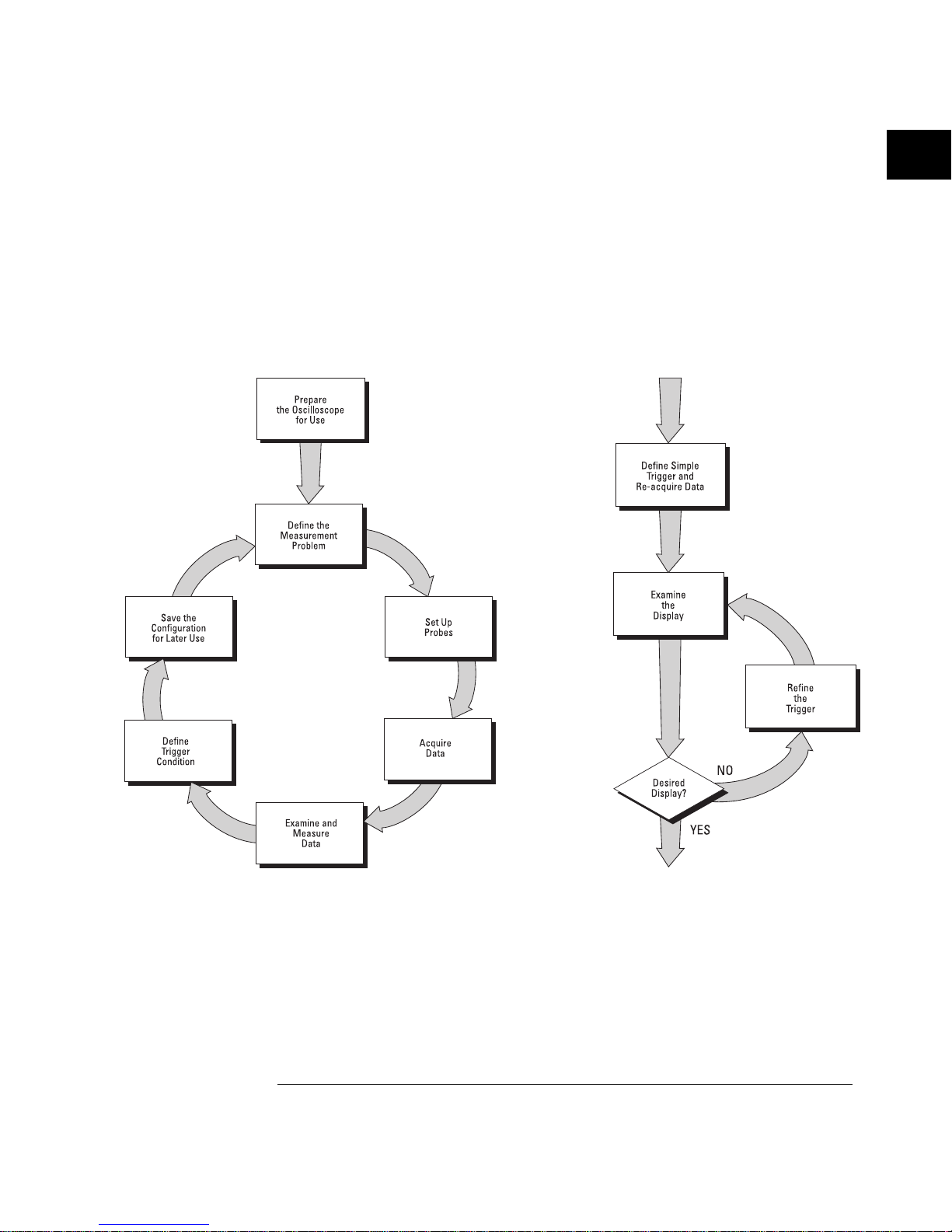
The HP 54645A/D high-speed display can be used to isolate
infrequently changing signals. You can then use the characteristics of
these signals to help refine the trigger specification. See figure 1-2
below. For more information on triggering, data acquisition, data
examination and measurement, and configuration, see chapters
3 and 4.
Using the HP 54645A/D Oscilloscopes, and Refini ng the Trigger Spec if i cation
Figure 1-1 Figure 1-2
Getting Started
1-3
Page 15

Preparing the Oscilloscope
To prepare your HP 54645A Oscilloscope or HP 54645D Mixed-Signal
Oscilloscope for use, you need to do the following tasks. After you
have completed them, you will be ready to use the oscilloscope.
In the following topics you will:
• Check package contents
• Adjust the handle
• Connect the cables
• Power-on the oscilloscope
• Use the digital probes to probe a circuit (with HP 54645D)
• Use the oscilloscope probes
• Adjust display brightness
1-4
Page 16

Check package contents
•
Verify that you received the following items and any optional
accessories in the HP 54645A/D packaging.
If anything is missing, contact your nearest Hewlett-Packard Sales Office. See
figure 1-3. If the shipment was damaged, contact the carrier, then contact the
nearest Hewlett-Packard Sales Office.
Accessories Supplied Accessories Available
Power cord (see the following t abl e)
HP 54620 -6 1801 16-channel pr obe cable (HP 54 645D only)
HP 10074 A 1. 5-meter, 10:1 Pr obe with readou t (qt y 2)
HP 5090- 4356 grabber s ( in resealable plastic bag; qty 20 )
(HP 54645D onl y—supplied w i th 16- channel cable)
HP 5959-9334 2" ground lead set (qty 5)
(HP 54645D onl y—supplied w i th 16- channel cable)
HP 54645A/D User & Service Guide
HP 54645A/D Programmer’s Guide
HP 54645A / D Pro gra m m er’s Reference (3.5 " diskette)
(disk is package d w ith Programmer’ s G ui de)
1252-7310 Banana ground plug (for HP 54645D)
HP 54650 A HP-IB Interface Module
HP 54652 B RS- 232/Parallel Interface Module
HP 54654A Operator’s Trainin g Ki t
HP 54657 A Me as. / Storage Module (HP-IB)
HP 54659 B RS- 232/Parallel /M eas./Storage M odul e
HP 34810 B BenchLink Soft w are for Windows
HP 5041- 9 409 Carr ying Case
HP 5062-73 45 Rackmount Kit
HP 10070A 1.5-meter, 1:1 Probe
HP 10100C 50-Ω Termination
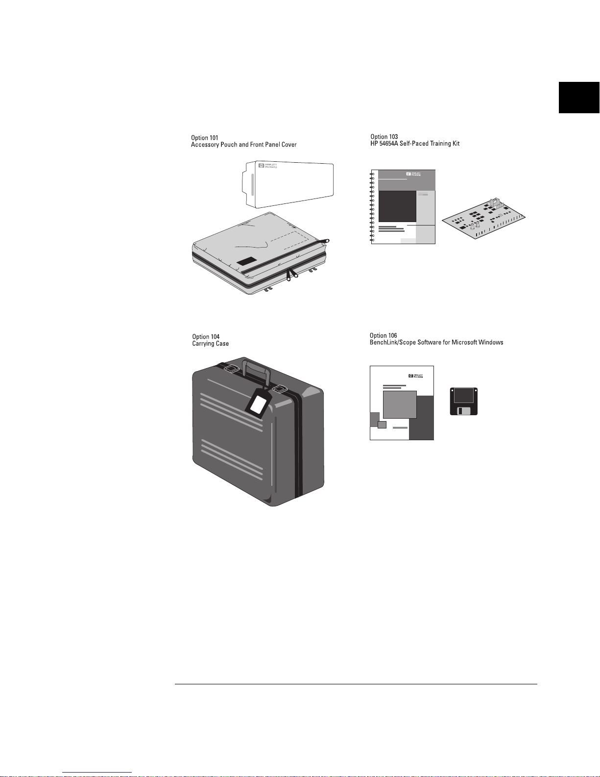
Options Available
Option 001 R S-0 3 Magnetic Inter ference Shield in g Added to CRT
Option 002 R E-0 2 Di splay Shield Added to CRT
Option 101 Accessory Pouch and Front-Panel Cover
Option 103 Operator’s Training Kit (HP 54654A)
Option 104 Car r ying Case (HP 5041 - 9 409)
Option 106 B enchLink Software (HP 34810B)
Power Cords (s ee t he f ol lo w in g table or the
"Replacement Parts" chapter)
Getting Started
Check package contents
1-5
Page 17
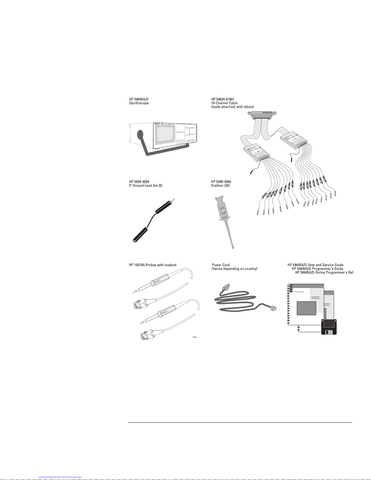
Items Sup pl ie d with the HP 546 45A/D Osci ll oscopes
Figure 1-3
Getting Started
Check package contents
1-6
Page 18
Optiona l Accessories f o r the HP 54645A / D Oscilloscopes
Figure 1-4
Getting Started
Check package contents
1-7
Page 19
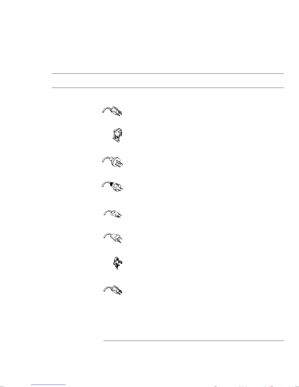
Table 1-1
Power Cords
Plug Type Cable Part
No.
Plug Description Length
in/cm
Color
Opt 903 (U.S.A.)
124V **
8120-1378 Straight (NEMA5-15P*) 90/228 Jade Gray
Opt 900 ( U . K . )
250V
8120-1351 Straight (BS136A*) 90/228 Gray
Opt 901 ( Australia)
250V
8120-1369 Straight
(NZSS198/ASC*)
79/200 Gray
Opt 902 (Europe)
250V
8120-1689
8120-2857
Straight (C EE7-Y11*)
Straight (S hi el ded)
79/200
79/200
Mint Gray
Coco Brown
Opt 906 ( Sw itzerland)
250V
8120-2104 Straight (SEV1011*) 79/200 Mint Gray
Opt 912 ( Denmark)
220V
8120-2957 Straight (DHCK107 *) 79/200 Mint Gray
Opt 917 (Africa)
250V
8120-4600 Straight (SABS164) 79/200 Jade Gray
Opt 918 (Japan)
100V
8120-4753 Straight Miti 90/230 Dark Gray
* Part number shown for plug is industry identifier for plug only.
Number show n for cable is HP pa rt number for comp lete cable incl uding plug.
** These cords ar e included in th e CSA certificat ion approval f or the equipment.
Getting Started
Check package contents
1-8
Page 20
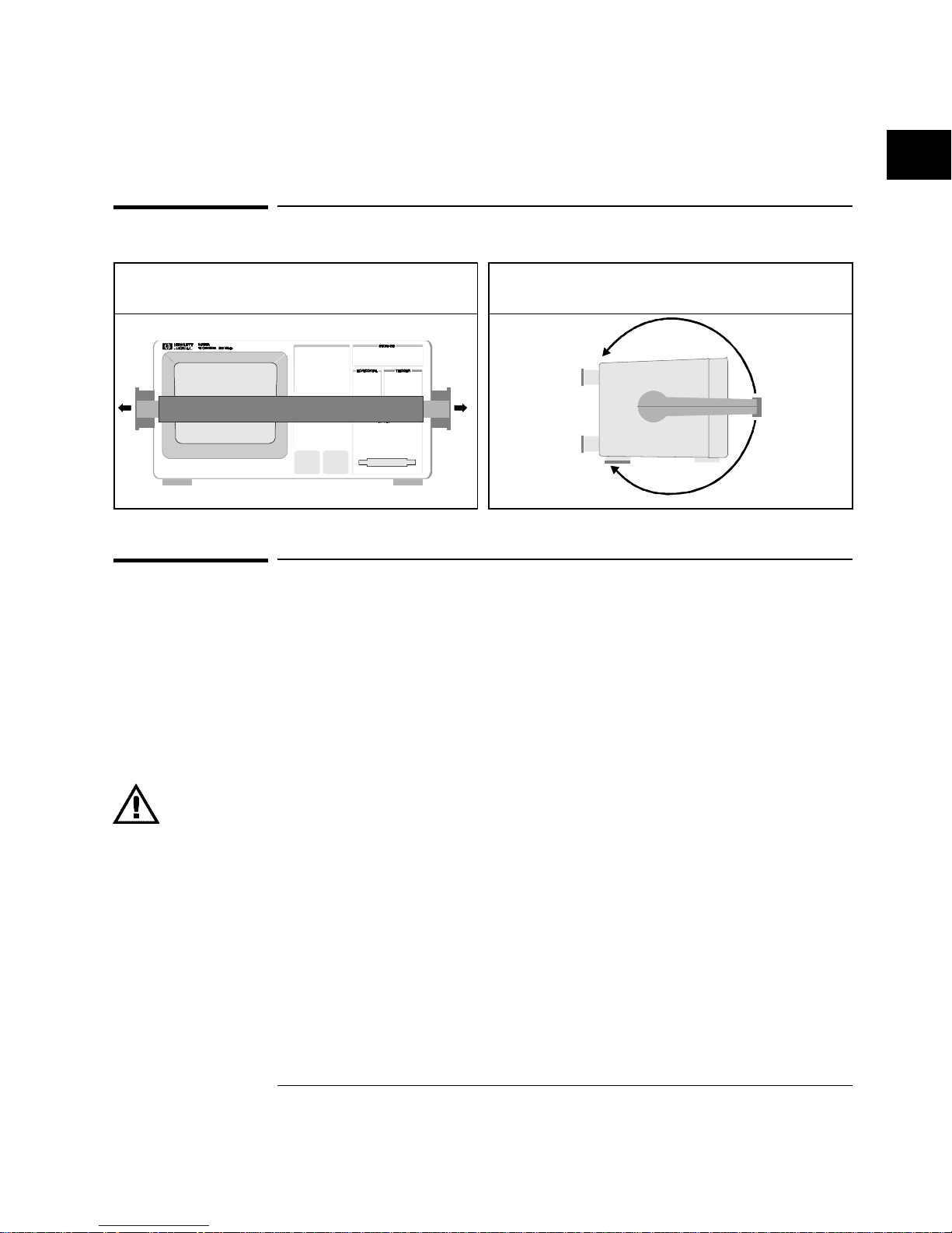
Adjust the handle
Connect the cables
1
Check to ensure that you received everything that is supplied with
the oscilloscope.
2
Connect the oscilloscope to power and turn it on.
3
Connect the cables:
If you are using this model: Do this:
HP 54645 A Oscilloscope
Connect the oscilloscope pr obe cables to osci lloscope
channels 1 and 2.
HP 54645 D Mixed-Signal
Oscillos cope
Connect the oscilloscope pr obe cables to osci lloscope
analog channel s A1 and A2.
Connect the di gi t al pro be cable to oscillo scope digital
channels D0-D15.
4
Then, connect the scope and/or digital probes to the circuit of
interest. Be sure to connect the ground leads.
You can use the front-panel calibration point as a stimulus while learning to
use the oscilloscope.
1
Grasp the handle pivot points on each side of the
instrument and pull the pivot out until it stops.
2
Without releasing the pivots, swivel the handle to
the desired position. Then release the pivots.
Getting Started
Adjust the handle
1-9
Page 21

Power-on the oscilloscope
1
Connect the power cord to the rear of the
HP 54645A/D, then to a suitable ac voltage
source.
The HP 54645A/D power supply
automatically adjusts for input line voltages
in the range 100 to 240 VAC. Therefore, you
do not need to adjust the input line voltage
setting. The line cord provided is matched
by HP to the country of origin. Ensure that
you have the correct line cord. See table 1-1.
2
Press the power switch.
The HP 54645A/D performs a self-test, then
shows the display. The instrument is ready
to use.
Getting Started
Power-on t he oscilloscop e
1-10
Page 22
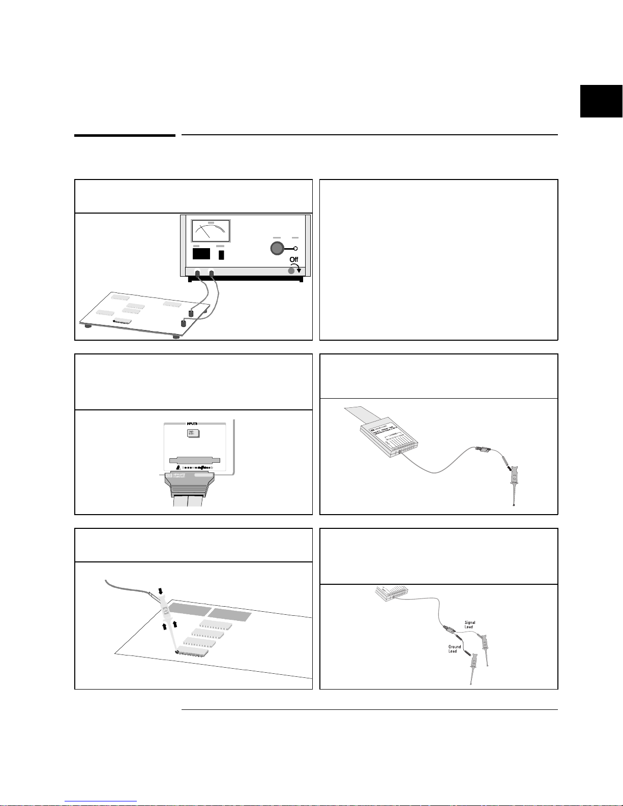
Using the digital probes to probe a circuit
1
If you feel it’s necessary, turn off the power
supply to the circuit under test.
Turning off power to the circuit under test
would only prevent damage that might occur
if you accidentally short two lines together
while connecting probes. You can leave the
HP 54645A/D powered on because no
voltage appears at the probes.
2
Connect the digital probe cable to HP 54645D.
The digital probe cable is indexed so you can
connect it only one way. You do
not
need to
power-off the HP 54645A/D.
3
Connect a grabber to one of the probe leads. Be
sure to connect the ground lead. (Other probe
leads are omitted from the figure for clarity.)
4
Connect the grabber to a node in the circuit you
want to test.
5
For high-speed signals, connect a ground lead to
the probe lead, connect a grabber to the ground
lead, and attach the grabber to ground in the
circuit under test.
Getting Started
Using the digital probes to probe a circuit
1-11
Page 23
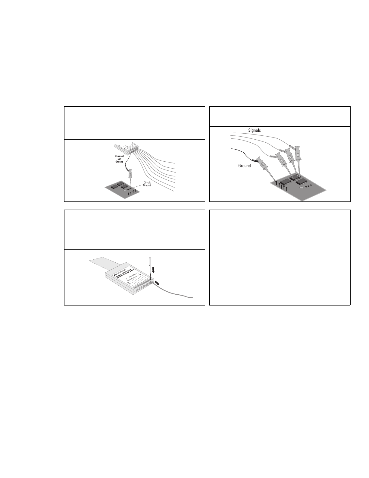
6
Connect the ground lead on each set of channels,
using a probe grabber. The ground lead improves
signal fidelity to the instrument, ensuring
accurate measurements.
7
Repeat steps 3 through 6 until you have
connected all points of interest.
8
If you need to remove a probe lead from the
cable, insert a paper clip or other small pointed
object into the side of the cable assembly, and
push to release the latch while pulling out the
probe lead.
Replacement parts are available. See the
“Replacement Parts” chapter for details.
Getting Started
Using the d igi tal probes to probe a circuit
1-12
Page 24
Using the oscilloscope probes
1
Connect the HP 10074A 1.5-meter, 10:1 oscilloscope probe BNC
connector to the channel 1 or 2 input on the HP 54645A or to channel
A1 or A2 on the HP 54645D.
2
Connect the probe grabber to the circuit point of interest. Be sure to
connect the ground lead to a ground point.
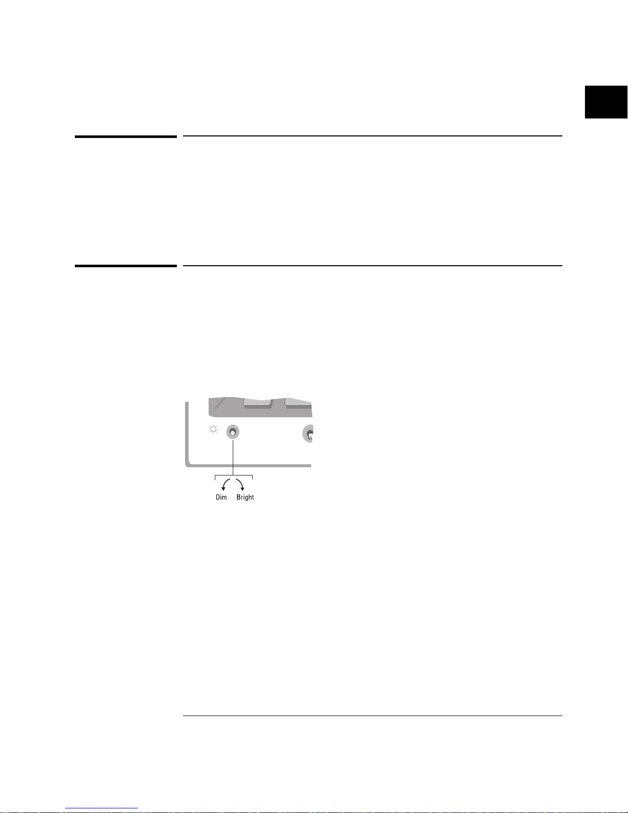
Adjust display brightness
The brightness control is at the lower left corner of the display.
•
To decrease display brightness, rotate the brightness control
counter-clockwise.
•
To increase display brightness, rotate the brightness control
clockwise.
HP 54645A/D Brightness Control
Figure 1-5
Getting Started
Using th e oscilloscope probes
1-13
Page 25

1-14
Page 26

2
Front-Panel Overview
Page 27

Front-Panel Overview
Before you make measurements using the HP 54645A Oscilloscope and
HP 54645D Mixed-Signal Oscilloscope, you must first set up the instrument
using front-panel controls. Then, make the measurement and read the
display results. See the following pages for descriptions of controls.
The HP 54645A/D operates much like an analog scope, but it can do much
more. Spending a few minutes to learn some of this capability will take you a
long way toward more productive troubleshooting. The “MegaZoom Concepts
and Oscilloscope Operation” chapter has more detail on the things to
consider while operating your oscilloscope.
The grey keys on the front panel bring up softkey menus on the display that
allow access to oscilloscope features. The white keys are instant action keys
and menus are not associated with them.
Throughout this book, the front-panel keys are denoted by a box around
the name of the key, and softkeys are denoted by a change in the text
type. For example,
Displa y
is the grey front-panel key on the front
panel, and Normal is a softkey appearing at the bottom of the display
directly above its corresponding softkey.
Important Oscilloscope Considerations
IMPORTAN T: R ead This Information!
It is extremely important that you read and understand the following informati on!
Using Single versus Run/Stop
The HP 54645A/D both have a Single key and a Run/Stop key. When you
press Run, the trigger processing and screen update rate are optimized over
the memory depth. Single acquisitions always use the maximum memory
available—at least twice as much memory as acquisitions captured in Run
mode—and the scope stores at least twice as many samples. At slow sweep
speeds, the oscilloscope operates at a higher sample rate when Single is used
to capture an acquisition, as opposed to running, due to the increased
memory available.
2-2
Page 28

Viewing Signal Detail with Display Mode
Remember how you had to constantly adjust the brightness on old analog
scopes to see a desired level of detail in a signal, or to see the signal at all?
With the HP 54645A/D, this is not necessary. The HP 54645A/D brightness
knob operates much like the brightness knob on your computer screen, so
you should set it to a level that makes for comfortable viewing, given the
room lighting, and leave it there. Then you can control the “detail” by
selecting a Display Mode: Normal, Peak Detect, or Average, as described in
the following paragraphs.
Normal Mode
Normal mode is the display mode that you will probably use for acquired
samples most of the time. It compresses up to 1 million acquisition points per
channel into a 4,000-point display record with vectors off, or a 2,000-point
record with vectors on.
The scope’s 200 MSa/s sampling speed specification means that samples are
taken every 5 ns. At the faster sweep speeds, the running display is built from
many individual triggers. If you press the Stop key, and pan and zoom
through the waveform, only the last trigger’s acquisition will be displayed.
Whether the scope is stopped or running, you see more detail as you zoom in,
and less as you zoom out. To keep from losing detail as you zoom out, switch
to the Peak Detect display mode. “Zoom” means you expand the waveform
using either the main or delayed sweep window. “Panning” the waveform
means you use the Delay knob to move it horizontally.
Peak Detect Mode
In Peak Detect display mode, any noise, peak, or signal wider than 5 ns will
be displayed, regardless of sweep speed. In Normal display mode, at faster
than 2 us/div, you would see a 5-ns peak, so peak detect has no effect at
sweep speeds faster than 2 us/div. Note that in this case the Pk status
indicator on the top line of the display is not highlighted.
Using Peak Detect and Autostore together is a powerful way to find spurious
signals and glitches.
Average Mode
Averaging is a way to pull the signal out of noise. Averaging works better than
either a bandwidth limit or a brightness control because the bandwidth is not
reduced.
Front-Pane l Ov erview
Important Os cilloscope Considerations
2-3
Page 29

The simplest averaging is “smoothing.” For example, the sample rate at a
Time/Div setting of ≥ 2 µs/div allows the extra 5-ns samples to be smoothed
together, smoothing the data into one sample, which is then displayed. As
with Peak Detect, smoothing has no effect at less than 2 µs/div. Smoothing
works on a single acquisition (even untriggered and single-shot). Averaging
(4, 8, 16, 32, 64, 128, and 256) needs a stable trigger, because in this mode
multiple acquisitions are averaged together. See the chapter “MegaZoom
Concepts and Oscilloscope Operation” for more information about smoothing.
Auto Single
As in Normal run mode, auto-trigger will generate a trigger for you if one is
not found in the predetermined time from when the trigger system is armed.
To take a single-shot acquisition, if you are not particularly interested in
triggering the acquisition (for example, if you are probing a known signal),
use Auto Single mode. If a trigger exists, it will be used; if a trigger does not
exist, an untriggered or auto-triggered acquisition will be taken for later
analysis.
Using Vectors
One of the most fundamental choices you must make about your display is
whether to draw vectors (connect the dots) between the samples, or simply
let the samples fill in the waveform. To some degree, this is a matter of
personal preference, but it also depends on the waveform.
•
You will probably operate the oscilloscope most often with vectors on.
Having vectors on slows the display of the oscilloscope, thus works better
for slower sweep speeds, peak detect, or average displays, and signals with
stable triggers.
•
Having vectors off works better for fast sweep speeds, normal displays, or
unstable triggers. Complex analog signals like video and eye diagrams
show more intensity information with vectors off. Turn vectors off when
the maximum display rate is required, or when highly complex or
multi-valued waveforms are displayed.
Front-Pan el Overview
Important Os cilloscope Considerations
2-4
Page 30

Delayed Sweep
Delayed sweep on the HP 54645A/D is a simultaneous display of the
waveform at two different sweep speeds. Because of the deep memory in the
MegaZoom technology, it is possible to capture the main display at 1 ms/div,
and redisplay the same trigger in the delayed display at any desired faster
time base.
There is no limit imposed on the zoom ratio between the main and delayed
displays. There is, however, a useful limit—when the samples are spaced so
far apart that they are of little value. See the chapter “MegaZoom Concepts
and Oscilloscope Operation” for more information about delayed sweep and
time reference.
Post Acquisition Processing
In addition to changing display parameters after the acquisition, you can do
all of the measurements and math functions after the acquisition.
Measurements and math functions will be recalculated as you pan and zoom
and turn on and off channels. As you zoom in and out on a signal, you affect
the resolution of the display. Because measurements and math functions are
performed on displayed data, you affect the resolution of functions and
measurements.
The two scope channels are always acquired, so you can turn them on and
look at them even if they were off during the acquisition. See “To turn digital
channels off (HP 54645D)” later in this chapter for more information about
the combination of events and displayed channels.
The XY horizontal display mode changes the oscilloscope display to
volts-versus-volts. The Roll horizontal display mode causes the waveform to
move across the screen from right to left.
Front-Pane l Ov erview
Important Os cilloscope Considerations
2-5
Page 31

HP 54645A/D Front Panels
HP 54645 A Oscilloscope Front Panel
Trigger
Keys
Display Storage
Keys
Softkeys
Brightness
Control
Power
Trigger
Input
Channel
Inputs/
Controls
Measurem ent
Keys
Horizont al
Controls
Calibration
Output
Figure 2-1
Front-Pan el Overview
HP 54645A/D Front Panels
2-6
Page 32

HP 54645 D Mixed-Signal O scilloscope Fro nt P anel
Trigger
Keys
Display Storage
Keys
Softkeys
Brightness
Control
Power
Analog Chan nel
Inputs/C ont rols
Measurem ent
Keys
Horizont al
Controls
Digital Cha nnel
Inputs/Controls
Calibration
Output
Figure 2-2
Front-Pane l Ov erview
HP 54645A/D Front Panels
2-7
Page 33

Description of Front-Panel Areas
Table 2-1
HP 54645A Front-Panel Areas
Front-Panel Areas Functions Control Knob s
Display Shows wav e f orm s, measurement results and i nstrument
configurati on settings.
Softkeys Set up various options for eac h m aj or function, varyi ng
dynamicall y depending on the re qui re d function.
Gene ral Co n trols Include various m easurement f unctions, confi gur ation,
screen and measurement r esults, curs ors , save/recal l,
printing, and A ut oscale functions.
Entry
VERTICAL
Channel Contr ol s
and Signal Inputs
Move or rearrange scope channel s, and turn them on or
off; set coupli ng, i nversion, and probe factors; and
connect the acquisition system to th e probes.
Volts/Div, Position (C hannel 1)
Volts/Div, Position (C hannel 2)
STORAGE
Keys
Control star t and stop of acqui si t io n, si ngl e t race,
persistent acquisition, and screen erasure.
HORIZONTAL
Controls
Adjust the tim e base, horizontal m ode, and main and
delayed sw eep f unctions.
Delay, Time/Div
TRIGGER
Controls an d Ext ernal
Input
Set up trigger m ode and trigger conditions. Level, Hol doff
External Trigger
Input
Triggers the oscilloscope fr om external instrum ents or
non-view abl e si gnals.
Brightnes s Control
(Display Intensity
Knob)
Adjust s di splay bright ness. Display Intensity
Front-Pan el Overview
Description of Front-Pa nel Areas
2-8
Page 34

Table 2-2
HP 54645D Front-Panel Areas
Front-Panel Areas Functions Control Knob s
Display Shows wav e f orm s, measurement results and i nstrument
configurati on settings.
Softkeys Set up various options for eac h m aj or function, varyi ng
dynamicall y depending on the re qui re d function.
Gene ral Co n trols Include various m easurement f unctions, confi gur ation,
screen, and measurement results, save/recall, printing,
and Autoscale functions.
Entry
ANALOG
Channel Contr ol s
and Signal Inputs
Move or rearrange analog chann el s A1 and A2, turn
them on or off, set coupling and inv er si on, and connect
the acquisi t io n system to the probes.
Volts/Div, Position (C hannel A1)
Volts/Div, Position (C hannel A2)
STORAGE
Keys
Control star t and stop of acqui si t io n, si ngl e t race,
persistent acquisition, and screen erasure.
HORIZONTAL
Controls
Adjust the tim e base, horizontal m ode, and main and
delayed sw eep f unctions.
Delay, Time/Div
TRIGGER
Controls
Set up trigger mode and trigger co ndi t io ns. Analog Level, Holdoff
DIGITAL
Channel
Inputs/C ont rols
Move or rearrange digital channels D0-15, tur n t hem on
or off, set threshold, define lab el s, and connect the
acquisit io n system to th e probes.
Position, Sele ct
Brightnes s Control
(Display Intensity
Knob)
Adjust s di splay bright ness. Display Intensity
Front-Pane l Ov erview
Description of Front-Pan el A reas
2-9
Page 35

Table 2-3
HP 54645A/D Front-Panel Specifics
General
Front-Panel Areas
Description Applies to U ni t:
Wavefo rm D isplay The wavefor m di splay area sho w s al l acquisition results. You
can change th e gra ticule or turn it off en tir el y using the
Display m enu.
HP 54645A/D
Softkeys Softkeys are s how n al ong the bottom of the display. Some
softkeys have an immediate action, such as taking you to
another men u or ini t ia ting a measurement.
Other soft keys allow you t o scr ol l thr ough a list of choices,
such as channels or trigger operators. You can scroll through
the choices by pressing the softkey repeatedly or by using
the Entry kn ob. For some sof tkeys, you can use the Entry
knob to scrol l through the choices. For chan nel lists, you can
always use the Select knob or Ent ry knob to scroll through
the choices.
Occasion ally a softke y l abel i s di splayed with two or more
choices belo w it, one of which is highlighted. The highli ght ed
choice is the one t hat is currently act i ve. Pr essing the softkey
toggles the hi ghl i ght to the other choi ce.
When seve ral softkeys are displayed with a labeled bar over
them, it mean s that either the s of tk eys are related and/ or that
the choices ar e m ut ual l y exclusive.
HP 54645A/D
Front-Pan el Overview
Description of Front-Pa nel Areas
2-10
Page 36

General
Front-Panel Areas
Description Applies to U ni t:
Keypad and Softkeys Some keys, such as On/O ff and Label also hav e special functio ns
while in the menus that they activate. Keys on the HP 54645A/D front
panels include the following:
White key s hav e an i m m edi ate action, such as starting or
stopping t he i nst r um ent. No menus are associated wit h w hi te
keys.
HP 54645A/D
Gray keys display softkey menus, allowing you to modify the
instrument ’ s measurement configuration .
HP 54645A/D
Softkeys bel ow th e di spl ay dynamical l y change to indicate
currently val id menu select i ons. A blank softkey has no function
in the selected menu.
HP 54645A/D
Control Knob s Control kno bs on the HP 54 645A/D fro nt panel s include the f ol lo w ing:
The Time/Div knob changes the current time base setting
(sweep speed) of the oscilloscope in Main or De la yed sweep.
The setting of the time base affects sample rate and other
instrument functions as w e ll. This control knob allows you to
zoom the waveform when the acqui sition is stopped.
HP 54645A/D
The Delay knob sets the delay tim e w i t h respect to the time
reference i n ei ther Main or Delayed sweep. This control kno b
allows you t o pan t hrough the wavef or m w hen the acquisiti on i s
stopped.
HP 54645A/D
The Select knob chooses th e di gi ta l ch annel on which the next
action will operate.
HP 54645D only
Front-Pane l Ov erview
Description of Front-Pan el A reas
2-11
Page 37

General
Front-Panel Areas
Description Applies to U ni t:
The Positi on knob moves the s el ect ed channel to a new v ert i cal
position on th e di spl ay. The HP 546 45 D has an additional Pos i tion
knob for the DI G I TAL channels.
HP 54645A/D
The Entry knob selects from m ul tipl e choices in men us. I t also
occasional ly dupl i cat es the function of the Select kn ob.
HP 54645A/D
The Trigger Level knob (HP 54645A) and Trigger Anal og Level
knob (HP 54 645D) set s t he trigger leve l for stabilizing a waveform
on the screen.
HP 54645A/D
The Trigger Holdoff knob keeps the oscilloscope from triggering
for a specified am ount of time.
HP 54645D
The display int ensity knob adj usts displa y brightness. HP 54645A/D
Displa y R egions The display is divi ded i nto the followin g regions:
Activity/status i ndi cators are along the top of the dis pl ay. These
include channel status when selecting the Pattern and
Advanced t rigger menus, and s how w het her digital channels are
turned on or off.
HP 54645D
Channel numb ers and l abels are on the left edge of the display. HP 546 45A/D
Wavefo rms are in the cente r of the display. HP 54645A/D
Measurem ent results and messages are jus t below the
waveform di splay area.
HP 54645A/D
Softkey label s are along the bottom of the display. HP 54645 A / D
Front-Pan el Overview
Description of Front-Pa nel Areas
2-12
Page 38

Front-Panel Areas Description Applies to U ni t:
Status Indicators Status ind ic at ors in cl ude the following:
Channels tha t ar e t urned off are visibl e onl y i f you select a
channel that is off by using the S el ect knob.
HP 54645D
Average mode is indicated by “Av”. Peak detect m ode
is
indicated by “Pk”.
These indicators are active when displayed in
inverse vi deo on the line abov e the display. When Time/Di v i s set
to 5 ns, and Peak Detect display mode is sel ected,
Pk
is
displayed at the top of the di splay, but has no effect, and is not
highlighted .
HP 54645A/D
Delay includes the time reference indicato r, th e offset marker s,
and the delay measurement. The solid triangle m ar ker (
▼
) points
to the trigger event in both the ma in and del ayed sweep; it
moves with the Delay knob. The ∇ symbol indicates the time
reference point . The time referenc e in di cat or is a left arrow (←)
if the trigger ev ent i s at the beginning of acqui sition memory , a
right arrow (→) if the event is at the end of acquis i tion memory,
and a down arrow (↓) if it is at the center. The offs et ma rkers
and delay measurement work together when you adjust the
Delay knob and H orizontal Mod e is set to Main, to indicat e how
far you have delayed the trigg er ev ent from the initial ti m e
reference pos i tion.
HP 54645A/D
Time/Div shows the tim e base setting. Time per divisi on is
variable from 2 ns/div to 50 s/div for H P 54645A, an d fr om 5 ns/div
to 50 s/div for HP 54645D.
HP 54645A/D
When Coupli ng i s set to AC, a small si ne wave is includ ed i n the
top left area of t he status line.
HP 54645A/D
Front-Pane l Ov erview
Description of Front-Pan el A reas
2-13
Page 39

Front-Panel Areas Description Applies to U ni t:
Trigger condit i on shows the curr ent tr i gger m ode. The A uto
Level and A ut o tr i gger m odes display th e "A uto" indicator.
For Edge trigger m ode, i t also shows the trigger condition and
channel numb er.
HP 54645A/D
In normal trig ger mo de, w hen the TV trigger mo de i s selected,
"TV" is displayed; when in Auto level or Auto modes, "TV" is
replaced by the "Auto" indicat or. Glitch trigge r mode displays a
positive or ne gative glitch signal next to the channel number.
HP 54645A/D
Pattern trigger mode displays "Pat" and Advanced Pattern
trigger mode dis pl ays "Adv".
HP 54645D
If the last ac qui sition was initiated by pres si ng the Single key,
the letters “Sngl” appear in thi s pos i tion (unless the las t si ngl e
acquisit io n w as auto trigger ed) .
HP 54645A/D
The acquisiti on i ndi cator shows t he current acquisi tion
condition, that is, whether the acquisition sys tem is running,
stopped, or in Autostore m ode.
HP 54645A/D
When the ins trum ent is in Normal trig ger mode, the Trigg er
condition ind ic ators flash whil e th e in strument is searching for
the trigger con di tion, which occurs after the pre-t rigger buffer is
full. When the i nstrument is in Aut o trigger mode, the wo rd
“Auto” fl ashes to the lef t of t he Trigger conditi on i ndi cat or if the
instrument di d not f in d the trigger and was th erefore triggere d
automatically after a time- out .
HP 54645A/D
When the dela yed horizontal m ode i s selected, a square symbol
appears at th e to p center of the activ i ty in di cator line. The
Time/Div next to this symbol is the delayed sweep s/div value.
When you press the Main/Delayed key , the d el ay value is
displayed briefly at th e bot tom of the displ ay.
HP 54645A/D
Front-Pan el Overview
Description of Front-Pa nel Areas
2-14
Page 40

Front-Panel Areas Description Applies to U ni t:
Channel Numbers The channel numbers ar e al w ays shown along the left edge of the
display.
HP 54645A/D
Channel La bel s You can assign channel labels to help you remember the function of
each channel in your ci rcuit, or disable t he l abel s to increase the
waveform di splay area.
HP 54645D only
Analog chan nel
voltage levels
Voltages f or ch annels 1 and 2 (anal og channels 1 and 2 on
HP 54645D) are set to 1 00 mV by defau lt, and range from 1.0 m V t o
5.0 V.
HP 54645A/D
Front-Pane l Ov erview
Description of Front-Pan el A reas
2-15
Page 41

Front-Panel Operation
By now you should be somewhat familiar with the VERTICAL or
ANALOG, STORAGE, HORIZONTAL, TRIGGER, and DIGITAL
groups of front-panel keys and knobs. You should also know how to
determine the setup of the oscilloscope by looking at the status line. If
you are unfamiliar with this information, we recommend that you read
the introductory material at the start of this manual.
HP 54645A and HP 54645D Channels
Because both the HP 54645A Oscilloscope and the HP 54645D
Mixed-Signal Oscilloscope have analog channels, the analog channel
topics in this chapter apply to both instruments. Whenever a topic
discusses the digital channels, that information applies only to the
HP 54645D Mixed-Signal Oscilloscope.
Oscilloscope Channels a re Labeled Differently
On the HP 54645A Oscilloscope, the analo g channels are l abeled 1 and 2 s i nce
there are no d i gi tal channels. On the HP 54645D Mixed-Signal Oscilloscope, the
analog channel s are label ed A1 and A2 to di stinguish th em from the digital
channels.
2-16
Page 42

To use oscilloscope channels to view a signal
•
To configure the instrument quickly, press
Autosc al e
.
•
To undo the effects of autoscale, press
Setup
, then press
Undo
Autoscale
.
•
To set the instrument to the factory-default measurement
configuration, press
Setup
, then press
Default Setup
.
Example Connect the oscilloscope probes for channels 1 and 2 for HP 54645A (or
A1 and A2 for HP 54645D) to the calibrator output on the front panel of
the instrument. Set the instrument to the factory default configuration by
pressing
Setup
, then Defa ult Se tup. Then press
Autoscale
. You
should see a display similar to the following.
HP 54645 D Sam pl e Autoscale Mea surement
Figure 2-3
Front-Pane l Ov erview
To use oscil los cope channels to view a signal
2-17
Page 43

To use digital channels to view a signal
•
To configure the instrument quickly, press
Autosc al e
.
•
To undo the effects of autoscale, press
Setup
, then press
Undo
Autoscale
.
•
To set the instrument to the factory-default measurement
configuration, press
Setup
, then press
Default Setup
.
Example Install grabbers on channels D0 and D1. Connect the probes for digital
channels D0 and D1 to the calibrator output on the front panel of the
instrument. Be sure to connect the ground lead. Set the instrument to
the factory default configuration by pressing
Setup
, then Default
Setup. Then press
Autoscale
. You should see a display similar to the
following.
HP 54645 D Sam pl e Autoscale Mea surement
Figure 2-4
Front-Pan el Overview
To use digit al channels to v iew a signal
2-18
Page 44

To display signals automatically using Autoscale
•
To configure the instrument quickly, press
Autosc al e
.
Autoscale displays all connected signals that have activity.
•
To undo the effects of autoscale, press
Setup
, then press
Undo
Autoscale
.
How Autoscale Works
If there is at least one oscilloscope or digital channel with an active signal, the
instrument turns off all other channels having no activity, and turns on all
channels having activity.
A scope channel is active if it is at least 10 mVp-p. Autoscale finds dc
(> 50 mV) on the HP 54645A/D scope channels. The scope channels that are
on are scaled vertically to best fit the screen.
For testing for digital channel activity, TTL, ECL, and variable thresholds are
used (in that order). Digital channels not previously displayed will be added
below those channels already displayed, with the lowest-numbered channel
at the top. Higher-numbered channels will be displayed in order down the
display.
The instrument checks for activity using a time window of 20 ms, allowing it
to recognize signals as slow as 50 Hz for autoscaling. If the instrument does
not find any channel with an active signal, it restores the setup to the
pre-autoscale state.
Front-Pane l Ov erview
To display signals automatically usin g Autoscale
2-19
Page 45

During Autoscale, the delay is set to 0.0 seconds, the Time/Div setting is a
function of the input signal (about 2 periods of the triggered signal on the
screen), and the triggering mode is set to edge. The instrument stays in
Normal or Peak Detect display mode, depending on what was selected when
Autoscale was performed. Vectors remain in the state they were before the
Autoscale.
Autoscale sets the trigger to a rising edge on a channel, checking the
channels in this priority: A2, A1, D15...D0.
Undo Autoscale
The Undo Autoscale function returns the instrument to the setup that
existed prior to Autoscale being activated.
To apply the default factory configuration
•
To set the instrument to the default factory measurement
configuration, press
Setup
, then press
Default Setup
.
The default configuration returns the instrument to the factory settings.
Refer to chapter 4, “MegaZoom Concepts and Oscilloscope Operation,”
for specific details.
Front-Pan el Overview
To apply the default factory configuratio n
2-20
Page 46

To adjust oscilloscope vertical scaling
This exercise guides you through the vertical keys, knobs, and status line.
1
Center the signal on the display using the Position knob.
The Position knob moves the signal vertically; the signal is calibrated. Notice
that as you turn the Position knob, a voltage value is displayed for a short
time, indicating how far the ground reference is located from the center of
the screen. Also notice that the ground symbol moves with the Position knob.
Measurement Hints
If the channel i s DC coupled, you can quickly measure t he DC compone nt of the
signal by s i m pl y noting its di stance from the ground symbol. If the chan nel i s AC
coupled, the DC componen t of the signal is removed, allowing you to use greater
sensitivi ty to display t he AC componen t of the signal.
2
Change the vertical setup and notice that each change affects the
status line differently. You can quickly determine the vertical setup
from the status line in the display.
•
Change the vertical sensitivity with the Volts/Div knob and notice
that it causes the status line to change.
•
Press
1
(for HP 54645A) or
A1
(for HP 54645D).
A softkey menu appears on the display, and the channel turns on
(or remains on if it was already turned on).
Front-Pane l Ov erview
To adjust os cilloscope ve rti cal scaling
2-21
Page 47

•
Toggle each softkey and notice which keys cause the status line to change.
Channels 1 and 2 have a vernier softkey that allows the Volts/Div
knob to change the vertical step size in smaller increments. These
smaller increments are calibrated, which result in accurate
measurements, even with the vernier turned on.
•
To turn the channel off, either press
1
(for HP 54645A) or
A1
(for HP 54645D) a second time or press the left-most softkey.
Invert Oper ati ng Hint
Inversion affects how a channel is dis pl ayed, but it does not affect triggering.
The trigger does not see th e i nversion, and thus is not affected. If the trigger is
set to a rising edge, it re m ai ns rising aft er i nversion.
Bandwidth Limit
The displayed bandwidth limit of the selected channel is 20 MHz, and is
available for channels 1 and 2.
Front-Pan el Overview
To adjust os cilloscope ve rti cal scaling
2-22
Page 48

To Expand the Vertical Signal
When changing the Volts/Div for analog channels, you can have the signal
expand (or compress) about the signal offset or the ground point. This works
well with two signals displayed, because you can position and see them both
on the screen while you change the amplitude.
•
To expand the signal about the offset, press
Print/Utility
.
Then select
System Config
and
Expand Verti cal Center
.
When you increase the Volts/Div to expand the signal about center, the top of
the waveform stays at the same level, while the bottom of the waveform
adjusts to fill the Volts/Div setting.
•
To expand the signal about ground, press
Print/ Ut ility
.
Then select
System Config
and
Expand Verti cal Ground
.
When you increase the Volts/Div to expand the signal about ground, the
bottom of the waveform stays at the same level, while the top of the
waveform adjusts to fill the Volts/Div setting.
Oscilloscope Probes
The HP 54645A/D Oscilloscopes have automatic probe sensing. If you are
using the probes supplied with the oscilloscope, or other probes with probe
sensing, the probe attenuation factor will be automatically set up by the
oscilloscope when automatic probe sensing is turned on. The default setting
is to have automatic probe sensing turned on. This is indicated by the
selection Auto n under the Probe softkey, where n is 1, 10, or 100.
If you are not using automatic probe sensing, toggle the Probe softkey to
change the attenuation factor to match the probe you are using.
Front-Pane l Ov erview
To adjust os cilloscope ve rti cal scaling
2-23
Page 49

To turn analog channels on and off
•
To turn off analog channel #1, press
1
(on the HP 54645A),
or
A1
(on the HP 54645D), then press the leftmost softkey
until
Off
is highlighted.
•
To turn off analog channel #2, press
2
(on the HP 54645A),
or
A2
(on the HP 54645D), then press the leftmost softkey
until
Off
is highlighted.
If you are already accessing the channel menu, you can press the On/Off key
or the channel key (1 or 2 for HP 54645A; A1 or A2 for HP 54645D) to toggle
a particular channel on or off.
To rearrange the analog channels
•
Rotate the channel 1 or 2 Position knob to choose a new location for
the analog channel.
Turning the Position knob counter-clockwise moves the channel down;
turning the knob clockwise moves the channel up.
Front-Pan el Overview
To turn analog channels on and off
2-24
Page 50

To turn digital channels on and off (HP 54645D)
•
To turn digital channels 0 through 7 on, press
D0-D15
, then
press the
D0 - D7 On
softkey. To turn these channels off, press the
Off
softkey.
•
To turn digital channels 8 through 15 on, press
D0-D15
, then
press the
D8 - D15 On
softkey. To turn these channels off, press
the
Off
softkey.
•
To turn on an individual channel, press
D0-D15
. Rotate the
Select knob until the channel is selected. Then, press
On
or
press
D0-D15
again to turn on the channel.
You can assign labels to channels that are off, or use them in a trigger
specification.
The two analog channels are always acquired, so you can turn them on and
look at them even if they were off during the acquisition. The combination of
events and displayed channels are:
Running— Bef ore Acquisiti on After St oppi ng Acquisiti on
D0-D7 D8-D15 D0-D7 D8-D15
Off Off Can be view ed Cann ot be vi ew ed
Off Any On Cannot be viewed Can all be viewe d
Any On Off Can all be viewed Cannot be viewed
Any On Any On Can all be view ed Can all be vi ew ed
Front-Pane l Ov erview
To turn digita l channels on and off (HP 54645D)
2-25
Page 51

To rearrange the digital channels (HP 54645D)
1
Turn the Select knob to choose the digital channel you want to move.
Only channels that are currently on may be moved.
2
Turn the Position knob to move the selected channel to a new
position.
Turning the Position knob counter-clockwise moves the channel down;
turning the knob clockwise moves the channel up.
The combination of the Select and Move knobs gives you a feature similar to
that of a waveform position control on an oscilloscope, except that you can
only move the waveform to certain discrete locations.
3
To change the general order in which channels are displayed,
press
D0-D15
. Then press the
Off/On
softkey or the
Reorder D1 5-D0
softkey.
When Reorder D15-D0 is pressed, the digital channels are displayed in
descending order, and the Reorder softkey is relabeled D0-D15. When the
D0-D15 softkey is pressed, the digital channels are displayed in ascending
order, and the Reorder softkey is relabeled D15-D0.
HP 54645D Digital Channels in Order
Channel activity
indicators appear
temporarily when
you acce ss the
D0-D1 5 menu,
pattern m enu, and
advance d pattern
menu.
Figure 2-5
Front-Pan el Overview
To rearrange the digital channels (HP 54645D)
2-26
Page 52

To operate the time base controls
The following exercise guides you through the time base keys, knobs, and
status line.
•
Turn the Time/Div knob and notice the change it makes to the status
line.
The Time/Div knob changes the sweep speed from 2 ns to 50 s (HP 54645A)
and from 5 ns to 50 s (HP 54645D) in a 1-2-5 step sequence, and the value is
displayed in the status line.
•
You can access the horizontal Vernier softkey by pressing the
Main/D el ayed
key.
The Vernier softkey allows you to change the sweep speed in smaller
increments with the Time/Div knob. These smaller increments are
calibrated, which result in accurate measurements, even with the
vernier turned on.
•
You can check the sample rate by pressing the
Main/D el ayed
key
when the instrument is running, during a single run, or when the
instrument is stopped. The sample rate is also displayed when the
acquisition stops or ends.
•
Turn the Delay knob and notice that its value is displayed in the status line.
The Delay knob moves the main sweep horizontally, and it pauses at
0.00 s, mimicking a mechanical detent. At the top and bottom of the
graticule is a solid triangle ( ▼ ) symbol and an open triangle ( ∇ )
symbol. The ▼ symbol indicates the trigger point and it moves with
the Delay knob. The ∇ symbol indicates the time reference point. If
the time reference softkey is set to left, the ∇ is located one graticule
in from the left side of the display. If the time reference softkey is set
to center, the ∇ is located at the center of the display. The delay
number tells you how far the reference point ∇ is located from the
trigger point ▼.
Front-Pane l Ov erview
To operat e the time base controls
2-27
Page 53

All events displayed left of the trigger point ▼ happened before the trigger
occurred, and these events are called pre-trigger information. You will find
this feature very useful because you can now see the events that led up to the
trigger point. Everything to the right of the trigger point ▼ is called
post-trigger information. The amount of delay range (pre-trigger and
post-trigger information) available depends on the sweep speed selected.
To start and stop an acquisition
•
To begin an acquisition, press the
Run/St op
key.
•
To begin a single acquisition, press the
Single
key.
The instrument begins acquiring data while searching for a trigger condition.
The RUN indicator is shown in the upper-right corner of the display. If a
trigger occurs, the acquired data is shown in the display.
•
To stop an acquisition in process, press the
Run/St op
key.
The instrument stops acquiring data, and the STOP indicator is shown in the
upper-right corner of the display. If the instrument was triggered (even by
auto triggering) and the pre-trigger and post-trigger buffers are full, the
results are displayed on the screen. If the buffers are not full, the waveform
display area will show nothing.
Front-Pan el Overview
To start and s top an acquisit ion
2-28
Page 54

To use the Entry and Select knobs
The Select knob (HP 54645D only) always changes the selected channel. In
most menus, its order is screen-oriented. In the simple pattern and advanced
pattern definition menus, it moves from the lowest to highest number on
clockwise rotation.
The Entry knob increments and decrements the selected field—for example,
glitch time and setup memory number. It also moves the selected cursor
when cursors are on. In menus where it doesn’t need to do these things (for
example, there is no field to increment or decrement, or cursors are turned
off), it adjusts the selected channel increment/decrement in a non-screen but
numerical order.
The Entry knob also occasionally duplicates the function of the Select knob.
Use the Entry knob to select channels, set trigger durations (ranges), and
select labels (HP 54645D only).
Front-Pane l Ov erview
To use the Entry and Select knobs
2-29
Page 55

To make cursor measurements
The following steps guide you through the front-panel Cursors key. You can
use the cursors to make custom voltage or time measurements on scope
signals, and timing measurements on digital channels.
1
Connect a signal to the oscilloscope and obtain a stable display.
2
Press
Cursor s
. View the cursor functions in the softkey menu:
Source selects a channel for the voltage cursor measurements
(1 and 2 for HP 54645A and A1 and A2 for HP 54645D). If a
Measurement/Storage module is installed in the oscilloscope, and
Function 2 is set to FFT and is turned on, you can select f1 or f2 for
the source.
Active Curs or includes voltage cursors V1 and V2, and time cursors t1
and t2. Pressing the voltage cursors alternates between V1 or V2, or
both V1 and V2. Pressing the time cursors alternates between t1 or t2,
or both t1 and t2. When both voltage cursors or both time cursors are
highlighted, they are selected, and they will move together on the
screen.
Voltage cursors do not apply to the HP 54645D digital channels.
If a Measurement/Storage module is installed in the oscilloscope, and
you select F2 as the source with F2 set to FFT, the active cursors
include f1 and f2. Use the Entry knob to change the active cursor.
Clear Cursors erases the cursor readings and removes the cursors from
the display.
Front-Pan el Overview
To make cursor measurements
2-30
Page 56

On HP 54645D, the Re adout softkey gives a reading of the time or
voltage cursor measurement.
•
For the time cursor readout, you can select Time, Hex, Binary, or
Degrees. Binary displays all digital channels by channel number. Hex
shows only the displayed channels, with the top channel displayed as
the most significant bit. When Active Cursor is t1/t2, the Readou t Ti m e
softkey sets the display to show the cursor positions in seconds, and the
Readout D egrees softkey shows the cursor positions in relative number
of degrees.
•
For the voltage cursor readout, you can select Volts or %. When Active
Cursor is V1/V2, the R eadout Volts % softkey sets the display to show the
cursor positions in volts when Volts is highlighted, and as a percentage
when % is highlighted.
You can expand the display with delayed sweep, then characterize the event
of interest with the cursors.
Pressing the Active Cursor softkey until both time cursors or both voltage
cursors are highlighted allows you to move them together when rotating the
Entry knob. You can move the cursors together to check for pulse width
variations in a pulse train.
Front-Pane l Ov erview
To make cursor measurements
2-31
Page 57

To use delayed sweep
Delayed sweep is a magnified portion of the main sweep. You can use
delayed sweep to locate and horizontally expand part of the main sweep for a
more detailed (high-resolution) analysis of signals.
The following steps show you how to use delayed sweep. Notice that the
steps are very similar to operating the delayed sweep in analog oscilloscopes.
1
Connect a signal to the oscilloscope and obtain a stable display.
2
Press
Main/D el ayed
.
3
Press the
Delayed
softkey.
The screen divides in half. The top half displays the main sweep, and the
bottom half displays an expanded portion of the main sweep. This expanded
portion of the main sweep is called the delayed sweep. Since both the main
and delayed sweeps are displayed, there are half as many vertical divisions so
the vertical scaling is doubled. Notice the changes in the status line. The top
half also has two solid vertical lines called markers. These markers show
what portion of the main sweep is expanded in the lower half. The size and
position of the delayed sweep are controlled by the Time/Div and Delay
knobs. The Time/Div next to the symbol is the delayed sweep sec/div.
The delay value is displayed temporarily at the bottom of the display.
•
To display the delay value of the delayed time base temporarily at the
bottom of the screen, press
Main/Delayed
.
•
To change the delay for the delayed sweep window, turn the Delay knob.
•
To change the Time/Div for the delayed sweep window, turn the Time/Div
knob.
•
To change the Time/Div for the main sweep window, select the main
sweep mode. Then turn the Time/Div knob.
Front-Pan el Overview
To use delayed sweep
2-32
Page 58

To modify the graticule
1
Press
Displa y
.
2
Press one of the
Grid
softkeys to define the graticule used for the
waveform area on the display.
•
Frame has a set of hash marks along the top and bottom of the display only.
Major divisions are indicated by longer hash marks.
•
Full has a set of hash marks through the center of the waveform display
area, with major divisions indicated by a full-height dotted line through the
waveform display.
•
None has only a border around the waveform display area.
Each major division in the graticule corresponds to the time given by the
Time/Div setting shown to the right of the delay value on the display.
Front-Pane l Ov erview
To modify the graticule
2-33
Page 59

To print the display
You can print the waveform display and status line to an HP printer or
Epson-compatible printer attached to one of these optional interface
modules:
HP 54650A HP-IB Interface Module
HP 54652A Parallel Interface Module
HP 54652B RS-232/Parallel Interface Module
HP 54657A Measurement/Storage Module (HP-IB)
HP 54659B Measurement/Storage Module (RS-232/Parallel)
1
If you have one of these modules installed, configure the module
first. If necessary, refer to documentation supplied with the module.
2
Press
Print/ Ut ility
.
3
Press
Print Screen
.
The current display is copied to the attached printer. You can stop printing
by pressing the Cancel Print softkey.
See the documentation for the interface module for information on installing
and configuring module interface parameters.
Front-Pan el Overview
To print the di splay
2-34
Page 60

3
Triggering HP 54645A/D Oscilloscopes
Page 61

Triggering HP 54645A/D Oscilloscopes
The HP 54645A/D Oscilloscopes provide a full set of features to help
automate your measurement tasks, including MegaZoom technology
to help you capture and examine the stored waveforms of interest,
even untriggered waveforms. With these oscilloscopes you can:
• Modify the way the oscilloscope acquires data.
• Set up simple or complex trigger conditions, as needed, to capture
only the sequence of events you want to examine.
The HP 54645A and HP 54645D have common triggering functionality:
• Trigger modes (Auto Lvl, Auto, Normal)
• Line triggering
• Glitch triggering
• TV triggering
• Mode/Coupling (including frequency and noise rejection—see
chapter 5)
• Holdoff and Trigger Level
• Slope/Edge Triggering
This chapter explains how to do all these things and more. If you are
not familiar with basic operations, see chapter 1, “Getting Started.”
See also “Triggering the HP 54645D Mixed-Signal Oscilloscope” in this
chapter for additional triggering functionality.
Glitch Trigger
In digital system design, a glitch is an unintentional or unexpected
signal transition, which may or may not pass through the logic
threshold.
The advanced glitch trigger menu lets you select the analog (A1 or A2
on HP 54645D) or digital (D0-D15 on HP 54645D) channel on which
to capture a glitch event. You specify the polarity and duration
qualifier—either less than (<), greater than (>), or a range—for the
glitch. The HP 54645D can capture glitches >8 nanoseconds and
<100 seconds.
3-2
Page 62

Selecting Trigger Modes and Conditions
The trigger mode affects the way in which the oscilloscope searches
for the trigger. Figure 3-1 shows the conceptual representation of
acquisition memory. Think of the trigger event as dividing acquisition
memory into a pre-trigger and post-trigger buffer. The position of the
trigger event in acquisition memory is defined by the time reference
point and the delay setting.
Acquisition Memory
To select a trigger mode: Auto Lvl, Auto, Normal
1
Press
Mode/C ou pling
.
2
Select the
Auto Lvl, Auto
, or
Normal
trigger softkey.
Auto Lvl and Auto modes
Use the Auto modes for signals other than low-repetitive-rate signals. To
display a dc signal, you must use the auto trigger mode since there are no
edges on which to trigger.
Auto Lvl mode is the same as Auto mode with an automatic trigger level
adjustment. The oscilloscope looks at the signal level on the signals, and if
the trigger level is out-of-range with respect to the signal, the scope adjusts
the trigger level back to the middle of the signal.
When you select Run, the oscilloscope operates by first filling the pre-trigger
buffer. It continues to flow data through this buffer while it searches for the
trigger. When a trigger is found, the pre-trigger buffer will contain the events
that occurred just before the trigger. If no trigger is found, the oscilloscope
generates a trigger and displays the data as though a trigger had occurred.
Figure 3-1
3-3
Page 63

When you select Single, the oscilloscope will fill acquisition memory, and
continue flowing data through the pre-trigger buffer until the auto trigger
overrides the searching and commands a trigger. At the end of the trace, the
scope will stop and display the results.
Normal mode
Use Normal trigger mode for low repetitive-rate signals. In this mode, the
oscilloscope has the same behavior whether the acquisition was initiated by
pressing Run/Stop or Single.
When the trigger event is found, the oscilloscope will fill the post-trigger
buffer and display the acquisition memory. If the acquisition was initiated
by
Run/St op
, the process repeats. The waveform data will be
scrolled onto the display as it is being acquired.
The oscilloscope begins filling the pre-trigger buffer with data. As soon as
that buffer is full, the oscilloscope will begin searching for the trigger event,
and will flash the trigger condition indicator on the status line to indicate it is
doing so. While searching for the trigger, the oscilloscope overflows the
pre-trigger buffer; the first data put into the buffer is the first pushed out
(FIFO).
In either Auto or Normal mode, the trigger may be missed completely under
certain conditions. This is because the oscilloscope will not recognize a
trigger event until the pre-trigger buffer is full. Suppose you set the Time/Div
knob to a slow sweep speed, such as 500 ms/div. If the trigger condition
occurs before the oscilloscope has filled the pre-trigger buffer, the trigger will
not be found. If you use Normal mode and wait for the trigger condition
indicator to flash before causing the action in the circuit, the oscilloscope will
always find the trigger condition correctly.
Some measurements you want to make will require you to take some action
in the circuit under test to cause the trigger event. Usually, these are
single-shot acquisitions, where you will use the Single key.
Triggerin g HP 54645A/D Oscilloscopes
To select a t rigger mode: Auto Lvl, Auto , Norm al
3-4
Page 64

To use holdoff
By setting the Holdoff, you can synchronize triggers. The oscilloscope will
trigger on one edge of the waveform, and ignore further edges until the
holdoff time expires. The oscilloscope will then re-arm the trigger circuit to
search for the next edge trigger. This allows the oscilloscope to trigger on a
repeating pattern in a waveform.
•
Turn the holdoff knob in the trigger section to increase and decrease
trigger holdoff time.
Holdoff Operating Hints
Holdoff keeps a trigger from occurring u ntil after a certai n am ount of time has
passed since the last tri gger. This feature is valuable when a wav eform cross es
the trigger level multip l e tim es during one period of the w aveform. W i thout
holdoff, the scope could trigger on each of t he crossings , producing a confusing
waveform.
With holdoff s et correctly , the scope always triggers on the same cros sing.
The correct h ol doff setting is typically s l i ghtly less than one period. S et the
holdoff to this time to generate a unique t ri gger point. Th i s action works even
though many w aveform periods pass between triggers, because the h ol doff
circuit operates on the in put signal continuously.
The HP 5464 5 A/D uses digital holdof f independent of tim e base settings.
The advantage of digital h ol doff is that it is a fixed number. As a resul t, changing
the time base settings does not affect the holdoff number; so, the oscilloscope
remains triggered . In c ont rast, the holdoff in analog oscilloscopes is a fu nction
of the time ba se setting, mak i ng it necess ary to re-adjus t t he holdoff each t i m e
you change the time base setting.
The rate of change of the holdoff adjustment knob depend s on the time base
setting you have selected. If you need a l engthy holdof f s etting, incre ase the
time/div s ett i ng on the time base, then make your coarse holdoff adjustment.
Now switch back to the ori gi nal time/div setting and mak e the fine adjustment to
reach the exact amount you w ant.
With HP’s MegaZoom technology, you can press St op, then pan and zoom
through the data to find where it repeats. Measure this tim e using the cursors,
then set this num ber to the holdoff.
Triggering HP 54645A/D Oscilloscopes
To use ho ldoff
3-5
Page 65

To trigger on a complex waveform
The difficulty in viewing a complex waveform is triggering on the signal. The
simplest trigger method is to trigger the oscilloscope on a sync pulse that is
associated with the waveform. If there is no sync pulse, use these steps to
trigger on a periodic complex waveform.
1
Connect a signal to the oscilloscope.
2
Set the trigger level to the middle of the waveform.
3
Adjust the Holdoff knob to synchronize the trigger of the
oscilloscope with the complex waveform.
Triggerin g HP 54645A/D Oscilloscopes
To trigger on a complex wav eform
3-6
Page 66

Triggering the HP 54645A Oscilloscope
The HP 54645A Oscilloscope allows you to synchronize the display to
the actions of the circuit under test by defining a trigger condition.
The triggering modes include Auto Lvl, Auto, and Normal. Triggering
types include Glitch, TV, and Slope/Edge and you can use channels 1
or 2, Line, or the External Trigger BNC for the source.
MegaZoom Technology Simplifies Triggering
With the buil t-in MegaZoom technology, you can simpl y Autoscale the
waveforms , then stop the sc ope to capture a waveform. You can then pan an d
zoom through the data to find a stable trigger point. Autoscale often produces a
triggered display.
To use external triggering
The external trigger input is only available on the HP 54645A Oscilloscope.
1
Connect a signal to the BNC labeled “External Trigger”.
The external trigger input has an input impedance of 1 MΩ, and can accept a
maximum signal of ±400 V (dc + peak ac) with a range of ±18 V. You can
connect the trigger output of other instruments to this external trigger input,
or use an oscilloscope probe, such as the HP 10074A.
2
Press
Slope/Glitch
. Then select the rising or falling edge, or
Glitch
.
If TV is selected, you cannot use the external trigger, and you must select
either channel 1 or channel 2. If you select glitch, define the polarity and
duration qualifier for the glitch.
3
Press
Source
. Then select
Ext
.
The external trigger is always dc coupled. If you select ac coupling or
low-frequency reject, these functions are not active until you change the
trigger source to channel 1, channel 2, or line. Notice that the status line and
softkeys reflect this.
3-7
Page 67

To trigger on an edge
1
Press
Source
.
2
Select
1, 2, Ext
, or
Line
as the trigger source.
You can choose a channel that is turned off as the source for the edge trigger.
You cannot select the Line trigger source when Glitch trigger mode is
selected.
3
Press
Slope/Glitch
to set the trigger condition.
4
Select either the rising edge or falling edge softkey to choose whether
the trigger will occur on the rising or falling edge of the input signal.
HP 54645 A Triggered on Rising Edge of Channel 2
Figure 3-2
Triggerin g HP 54645A/D Oscilloscopes
To trigger on an edge
3-8
Page 68

To use glitch triggering
1
Press
Slope/Glitch
. Then select
Glitch
.
2
Select
Glitch Men u
.
3
Define the polarity, duration qualifier, and duration time for the glitch.
HP 54645 A Triggered on Glitch on Channel 1
Figure 3-3
Triggering HP 54645A/D Oscilloscopes
To use glit ch triggering
3-9
Page 69

To use line triggering
•
Press
Source
. Then select
Line
.
To use TV triggering
1
Press
Source
. Select
1
or 2 for the Trigger Source channel.
2
Press
Slope/Glitch
. Then select
TV
.
3
Select
TV Menu
.
4
Select positive or negative polarity.
5
Select the TV mode.
•
Pressing
Field 1
triggers on the video signal field 1 portion (odd fields).
•
Pressing
Field 2
triggers on the video signal field 2 portion (even fields).
•
Pressing
Line
triggers on the start of the first line that occurs after the
scope starts.
•
Pressing
Vertical
provides vertical triggering—at the beginning of both
Field 1 and Field 2.
Triggerin g HP 54645A/D Oscilloscopes
To use line t riggering
3-10
Page 70

Triggering the HP 54645D Mixed-Signal
Oscilloscope
The HP 54645D Mixed-Signal Oscilloscope allows you to synchronize
the oscilloscope display to the actions of the circuit under test by
defining a trigger condition.
The trigger types include edge, pattern, and advanced, allowing you to
match the complexity of the trigger to that of the data you want to
capture. The triggering modes include Auto Lvl, Auto, and Normal.
Advanced triggering consists of Glitch, Advanced Pattern, and TV.
Depending on the trigger selections and conditions, you can use
analog channels A1 or A2, Line, or D0-D15 for the trigger source.
MegaZoom Technology Simplifies Triggering
With the buil t-in MegaZoom technology, you can simpl y Autoscale the
waveforms , then stop the sc ope to capture a waveform. You can then pan an d
zoom through the data to find a stable trigger point. Autoscale often produces a
triggered display.
3-11
Page 71

Trigger types
These trigger types are available:
•
Edge trigger
•
Pattern trigger
•
Advanced trigger
Changes to the trigger specification are applied when you make them. If the
oscilloscope is stopped when you change a trigger specification, the scope
will use the new specification when you press Run/Stop, Single, or Autostore.
If the oscilloscope is running when you change a triggering specification, it
uses the new trigger definition when it starts the next acquisition. You select
the trigger type by pressing the key associated with the desired trigger type.
Edge Trigger
In edge trigger, you define a single rising or falling edge that must be
recognized on any input channel to satisfy the trigger condition.
Edge trigger is best when there is a unique waveform edge that defines the
events you want to capture. For example, a pulse that defines the beginning
of a pulse train on another channel will often make a good edge trigger.
Edge triggering is the simplest trigger mode, and the easiest to use. However,
its simplicity can lead to situations where more triggering power is needed.
Often the device under test needs more than a single rising or falling edge to
locate a specific point in its operation.
Triggerin g HP 54645A/D Oscilloscopes
Trigger types
3-12
Page 72

Glitch Trigger
The advanced glitch trigger menu lets you select the analog (A1 or A2) or
digital (D0-D15) channel on which to capture a glitch event. You specify the
polarity and duration qualifier—either less than (<), greater than (>), or a
range—for the glitch. The HP 54645D can capture glitches >8 nanoseconds
and <100 seconds.
Pattern Trigger
In pattern trigger, you define a pattern of highs, lows, and don’t care levels
that must be recognized across the input channels. The pattern may be
combined with one edge on any one input channel to form the complete
trigger specification.
A Pattern trigger is best when there is a unique pattern that occurs across a
group of signals, and the pattern defines the events you want to capture. For
example, suppose you have a state machine that outputs a series of hex
digits, and only outputs the digit “A” once in every sequence. You can use a
pattern trigger to capture this event, perhaps qualified with the state
machine clock.
Pattern trigger is less useful when the same pattern occurs many times, and
most of those occurrences have little to do with the events you want to
capture. For example, suppose that this same state machine generates
hundreds of states, and the state “C” occurs several times in the sequence,
with a different sequence of states after each occurrence. A pattern trigger
will not provide a stable waveform display.
The pattern trigger occurs when the pattern is entered; that is, the trigger
condition is satisfied as soon as the input waveforms have transitioned from a
condition not matching the pattern to a condition matching the pattern. You
can use an edge to further qualify the trigger condition. For example, you
may want the oscilloscope to trigger when a certain pattern is present and a
clock edge occurs.
The trigger pattern can include high and low values on the oscilloscope A1
and A2 channels. You control the trigger level with the Analog Level knob.
Logical Combination within Terms
In the pattern trigger, all settings within the pattern are logically ANDed; that
is, all conditions on the pattern, and the edge if specified, must be satisfied
before the oscilloscope will trigger.
Triggering HP 54645A/D Oscilloscopes
Trigger types
3-13
Page 73

Specifying a Logic Threshold
You can specify a threshold for the logic channels. See “To change the logic
threshold for input signals” in chapter 4 for information about setting a
threshold on the HP 54645D.
Advanced Pattern Trigger
In advanced pattern trigger, you define a maximum of two pattern and
edge sources that are combined with a variety of operators to form the
complete trigger specification.
Advanced pattern trigger is best when the events you want to capture are
defined by a series of waveform events in the system, and neither pattern
mode nor edge mode are capable of clearly resolving the necessary sequence.
For example, suppose the events you want to capture are defined by a
pattern with a certain minimum duration, or by a pattern followed by another
pattern. Advanced pattern trigger gives you this and more.
HP 54645 D Advanced Pattern Triggering Ov er view Menu
Figure 3-4
Triggerin g HP 54645A/D Oscilloscopes
Trigger types
3-14
Page 74

Sharing of Sources
The source definitions for the simple pattern trigger are shared with the
Pattern 1 and Edge 1 sources of the advanced pattern trigger specification.
Thus, changes to the simple pattern trigger will affect that specification, and
changes to Pattern 1 and Edge 1 in the advanced pattern trigger specification
will affect the simple pattern trigger.
Logical Com binations
In advanced trigger, sett i ngs within pattern terms are l ogi cally ANDed. Settings
within the second edge ter m are l ogically O R ed w i th the first edge term. Th us ,
only one of those edge spe ci fications must be satisfied to satisfy the edge term.
TV Trigger
The TV trigger only operates on the analog channels. The TV trigger can be
set to trigger on the vertical interval, Field 1, Field 2, or Line. In Line mode,
the oscilloscope will trigger on the start of the first line that occurs after the
scope starts.
The advanced TV trigger requires two vertical divisions of display amplitude.
On HP 54645D, you must specify either analog channel (A1 or A2) as the
trigger source. You specify the polarity—either positive or negative sync
pulses—and the TV mode. The Field 1 TV mode triggers on the field 1
portion of the video signal, Field 2 triggers on the field 2 portion of the video
signal, and Line triggers on all the TV line sync pulses.
On HP 54645D, pressing Field 1 and Field 2 simultaneously gives vertical
triggering.
You can select the high-frequency reject in the Mode/Coupling menu to
control a 500-kHz, low-pass filter in the trigger path.
Triggering HP 54645A/D Oscilloscopes
Trigger types
3-15
Page 75

To define an edge trigger
1
Press
Edge
.
2
Select a channel as the trigger source using either the Select knob or
by pressing a
Trigger Source
softkey.
You can choose a channel that is turned off as the source for the edge
trigger.
3
Press one of the
Edge
softkeys to choose whether the trigger will
occur on the rising or falling edge.
Rotating the Select Knob does not Affect Trigger Channel
When selecting a digital channel as th e source, after you have set th e edge
trigger condition, and sel ected another m enu, continuously rotating t he S elect
knob will not affect the channel used for the trigger condition. The trigger edge
is not chang ed until you select a slope. This frees u p the Select knob for other
operations , such as measu rem ents.
To use line triggering
This power line edge triggering, when selected, overrides any other settings.
Do not confuse the power line triggering with TV line triggering.
1
Press
Edge
. Then select
Line
.
2
Select the rising or falling edge softkey.
Triggerin g HP 54645A/D Oscilloscopes
To define an edge trigger
3-16
Page 76

To define a pattern trigger
1
Press
Patter n
.
2
For each analog channel (A1 or A2) or digital channel (D0-D15) you
want to include in the desired pattern, press the
Source
softkey to
select the channel, or rotate the Entry knob or the Select knob.
3
Then, press one of these softkeys to set the condition the
oscilloscope will recognize as part of the pattern for that channel:
•
L
for a logic low
•
H
for a logic high
•
X
to ignore this channel
•
Rising or falling edge
Specifying an Edge in a Pattern
You are allowed to s pecify only one risi ng or falling edge term in the pattern. If
you define a n edge term, then select a diff erent channel i n the pattern and
define anoth er edge term, the previous edge definition i s changed to a don’ t
care.
Source Definitions for Simple Pattern Trigger Affect A dv anced Trigger
The source d efinitions for t he simple pat tern trigger are s hared with the
Pattern 1 and Edge 1 sourc e definitions of the advanced pattern trigg er
specification. Th us , changes to the simple pat te rn t rigger will affect that
specificat i on, and changes t o P attern 1 and Edge 1 in the adv anced trigger
specification will affect the regular pat te rn trigger. Defining patterns for the t w o
trigger types differs. See “To define an advanced pat tern trigger.”
Triggering HP 54645A/D Oscilloscopes
To define a pattern trigger
3-17
Page 77

To use glitch triggering
1
Press
Advancd
. Then select
Glitch
.
2
Select
Glitch Men u
.
3
Select the analog channel (A1 or A2) or digital channel (D0-D15)
source for the trigger by pressing the
Source
softkey until the desired
source is highlighted.
4
Select positive or negative polarity for the glitch to capture.
5
Select the time qualifier (<, less than a specified width; >, greater
than a specified width; or ><, within minimum and maximum limits)
for the glitch, and rotate the Entry knob or press the softkey to
increase the duration time.
Triggerin g HP 54645A/D Oscilloscopes
To use glitc h triggering
3-18
Page 78

To define an advanced pattern trigger
The advanced triggering operation depends on previous selections in the
Advanced Trigger menu.
1
Press
Advanc d
. Then select
Pattern
.
2
Press the
Overview
softkey to turn on the trigger overview, if desired.
The trigger overview display shows all the choices available in this menu.
3
Select
Pattern Me nu
.
4
Choose the trigger operator by pressing the
Operator
softkey until the
desired operator is shown.
The following table lists the trigger operators and the sources with which
they can be used. The sources you specify later in this procedure can limit
your choice of trigger operators, and your choice of trigger operators can
limit which sources are available. For example, the operator “Exited” applies
only to Pattern 1, Not Pattern 1, Pattern 2, and Not Pattern 2 individually,
but not to all of them at once.
Table 3-1
Trigger Operators and Sources
Operator # of Sources Valid Sources
Duration
(> time, < time,
Range)
One Pat 1, Not = Pat 1
Pat 2, Not = Pat 2
Entered, Exited One Pat 1, Not = Pat 1
Pat 2, Not = Pat 2
AND, OR, Then Two Pat 1, Not = Pat 1
Pat 2, Not = Pat 2
Edge 1, Edge 2
Pat 1 & Edge 1
Pat 2 & Edge 2
Triggering HP 54645A/D Oscilloscopes
To define an advanced pattern trigger
3-19
Page 79

5
Select the source(s) for the trigger operator by pressing the leftmost
Source
softkey until the desired source is highlighted.
Refer to the table of trigger operators and sources to see the sources and
operators with which they can be used.
The oscilloscope will allow you to choose combinations of sources that are
redundant, such as “Pattern 1 AND Pattern 1”, or combinations that will
create a null trigger condition, such as “Pattern 1 AND Not Pattern 1”.
6
Define the source pattern(s) by pressing the
Source Define
softkey.
If you combined patterns and edges in the same source term, you must
separately select each as the source, set up the source, then select the
combined pattern and edge again.
7
Set the parameters for the trigger operator, if necessary.
For the Duration operators (> time, < time, range), press/hold the duration
value softkey or rotate the Entry knob to set the duration.
Duration > time
When this operator is sel ected, you hav e two choices for trigger:
Trigger At: Timout
(default) – tr i gger when > time criteria is m et after you ent er
the pattern. Thi s is useful for conditions where the pat tern occurs and you want
to see the waveform, but no e dge f ollows immediately.
Trigger At: P at Exit
– trigger when you exit the pattern.
8
To set up an edge trigger source, do the following:
a
Select a channel for the source.
•
To choose whether the trigger will occur on the rising or falling edge,
press one of the
Edge Select
softkeys.
•
To set a channel to a don’t care trigger state, press the X softkey.
•
To clear all edge settings, press the
Clear Edge(s)
softkey.
In Edge1, you can select only one edge. You may select multiple edges
in Edge2; those edges are logically ORed.
b
Repeat step a for all channel sources you want to define.
c
Press
Previous Menu
to return to the Advanced Pattern Trigger menu.
Triggerin g HP 54645A/D Oscilloscopes
To define an advanced pattern trigger
3-20
Page 80

9
To set up a pattern trigger source, do the following:
a
Select a channel for the source.
•
To set the condition for that channel, press the L, H, or X softkey.
•
To clear the conditions for all channels, press
Clear Patt ern
.
b
Repeat step a for all channel sources you want to define.
c
Press
Previous Menu
to return to the Advanced Pattern Trigger menu.
Entered and Exited
In the table of trigger operators and sources:
•
Entered means that the trigger qualifier is satisfied as soon as the input
waveforms have transitioned from a state not matching the pattern to a
state matching that pattern. In an edge term, or a pattern and edge term,
the edge transition is where "entered" is defined.
•
Exited means that the trigger qualifier is satisfied when the input
waveforms transition out of a state matching the pattern to a state not
matching the pattern.
Advanced pattern trigger can help you solve difficult data acquisition
problems. When setting up an advanced trigger, remember:
•
Follow the setup rules.
•
Have a clear picture of the event sequence you are trying to capture, and
understand how the advanced trigger capabilities relate to those events.
The MegaZoom technology’s deep memory and pan and zoom capabilities
greatly simplify this.
Triggering HP 54645A/D Oscilloscopes
To define an advanced pattern trigger
3-21
Page 81

Setup rules
Remembering the following rules will make it easier to work with the
advanced triggering capabilities:
•
Duration operators are valid when only pattern terms are involved.
Duration is not selectable when any edge term is selected as a source.
•
When you have selected a combination source, like Pattern 1 AND Edge 1,
you cannot directly define the pattern or edge. You must instead select
Pattern 1 as the source, define the pattern, then select Edge 1 as the
source and define the edge. The softkeys change to reflect this.
Understand and relate waveform events to oscilloscope capabilities
The key to setting up a useful waveform display is choosing a known
sequence of waveform events to which you can apply the advanced trigger
capabilities. The HP MegaZoom technology greatly simplifies this task. You
simply press Stop, then pan and zoom through the waveform to find a good
trigger event.
To find these events, you can also ask questions about the waveform, keeping
in mind the capabilities of the oscilloscope.
•
Does the input data always repeat with respect to a particular waveform’s
high or low period of constant duration?
•
Is there a sequence of waveform events that define the data of interest?
For example, is there a state machine, where the hypothetical sequence
“ac” leads to the events of interest, where “ab” does not?
Triggerin g HP 54645A/D Oscilloscopes
To define an advanced pattern trigger
3-22
Page 82

Example
Suppose you have a pulse train where one of the pulses is of constant
duration (4 µs) and all other signals of interest are repeated with that pulse
train, as shown in the following figure.
Pulse Train with Constant Duration Pulse
To trigger the oscilloscope on that pulse, you can use one of the trigger setup
in the following table:
Source Operator and
Parameters
Pattern/Edge
Pattern 1 Duration > 3.9 µs H on channel 0, others don’t care
Glitch on chan nel 1 Duration > 3.9 µs,
< 4.1 µs
Example
Suppose you have a state machine whose three outputs, Q0 through Q2,
output the decimal sequence 0-1-6-0-6-1. Q2 is the most significant bit, as
shown in the following figure.
Sequential Output from State Machine
If you try to trigger on any of the single output patterns 0, 1, or 6, the display
will not be stable. However, you can use the “Then” operator to trigger on the
sequence of pattern “0” followed by pattern “1.” If Q2, Q1, and Q0 are
connected to channels D2, D1, and D0 respectively, you can use the setup in
the following table to trigger the oscilloscope.
µ
Figure 3-5
Figure 3-6
Triggering HP 54645A/D Oscilloscopes
To define an advanced pattern trigger
3-23
Page 83

Source Operator and
Parameters
Pattern/Edge
Pattern 1 Then L on channels D2, D1, and D0, others don’t
care
Pattern 2 L on channels 2 and 1, H on channe l 0 ,
others don’t care
All Qualifiers must be Sat is fi ed to Trigger the Oscilloscope
When settin g up an advanced t ri gger, remember that all requi red events m ust
be satisfied to trigger the oscilloscope.
Pattern 1 and Edge 1 are Shared Sources
Source defini tions for Pat tern 1 and Edge 1 are shared wi th the pattern tr i gger
specification. Th us, source changes will affect that specification, and cha nges
to the simple pattern trigger specification will af fe ct the definitions of Patte rn 1
and Edge 1.
High-Frequency Pattern R eject
When you se t a pattern that co ntains more than one digital channel, and no
edges or ana l og channels, it i s possible t hat false patterns may occur w hen two
digital cha nnel s change at the same time, due to minor sk ew differences .
In the previous example, w hen Q2-Q0 change from 1 to 6, Q2 and Q1 rise at the
same time This provides potential for seeing a false “10” or “01” on those two
channels. In the HP 54645D, we require the pattern to be present long enough to
be sampled at least twice at 400 MHz to eliminate this possibility. This method
prevents fa l se triggers on sim ultaneous edges.
Triggerin g HP 54645A/D Oscilloscopes
To define an advanced pattern trigger
3-24
Page 84

4
MegaZoom Concepts and
Oscilloscope Operation
Page 85

MegaZoom Concepts and Oscilloscope
Operation
This chapter gives an overview of some oscilloscope concepts that will
help you make better measurements. It discusses the relationship
between the time base setting and other time-dependent oscilloscope
functions, explains how to achieve the most accurate signal fidelity
through good probing practices, and describes how glitch detection
works.
Oscilloscopes with HP’s MegaZoom Technology
The information in this chapter applies to both the HP 54645A and
HP 54645D Oscilloscope models because both are based on HP’s
MegaZoom technology.
4-2
Page 86

MegaZoom Concepts
MegaZoom technology combines the advantages of conventional
deep-memory digital oscilloscopes with the responsiveness and
update rate of traditional analog oscilloscopes. Conventional
deep-memory digital oscilloscopes are known for their ability to
capture long time intervals while still maintaining high sample rates.
MegaZoom technology keeps the deep-memory advantages, without
the conventional deep-memory disadvantages of an unresponsive user
interface (while panning and zooming through the data) and poor
signal update rate.
MegaZoom technology incorporates a multi-processor architecture in
the signal data path between the scope probe and the scope display.
This yields an instrument that responds instantly to pan and zoom
controls while exploring the acquired data. MegaZoom technology
combines update rate, instant control response, and deep-memory
innovations to allow you to capture long time periods with high
sample rates, and instantly zoom in on the signal details of interest
either while stopped or running. Deep-memory, front-panel
responsiveness and display update rate are combined into one
oscilloscope, with no special mode or memory depth selection.
MegaZoom Technology’s Deep Memory I m proves Timing R esolution
The HP MegaZoom technology used in th e HP 54645A/D oscilloscopes keeps the
sampling r ate at the maximum for all sw eep speeds of 50 0 µs/div and faster in
Single mode, and 200 µs/d i v and faster in R un m ode.
4-3
Page 87

Deep Memory
The primary advantage of a deep-memory oscilloscope is sustained sample
rate, allowing you to capture at the maximum sample rate and capture a
much longer time window. For example, you may want to capture a fast
digital event, such as an interrupt line being asserted, while being able to look
far out in time to see when the line was de-asserted. This may require a fast
sample rate to examine the signal fidelity of the interrupt edge, and also
long-time capture to determine how long the interrupt line was asserted.
Another advantage is the ability to capture relatively longer periods of time
or slow time-per-division settings at an adequate sample rate. This allows
you to capture a long event, such as an oscillator starting up, or two events
separated by a long time, such that you can see the entire time frame of
interest. To see the event, the scope must have captured the information at a
fast enough sample rate so that you can see the signal details of interest.
MegaZoom C oncepts
Deep Memory
4-4
Page 88

Oscilloscope Responsiveness
An important element of an oscilloscope is how responsive it is to control
changes. After a control is changed, such as the time/division, if you must
wait for the test instrument to respond, the feedback loop between the
instrument and you can become difficult. You could confuse adjustments
because of the delay between making a change to the instrument and seeing
the effect of that change take place.
MegaZoom Technology
In MegaZoom technology, the primary task of processing acquisition memory
into scope waveforms using proprietary display techniques is distributed to
waveform translator hardware. The processor’s primary responsibility is to
scan the keyboard and manage I/O ports. Because the dedicated waveform
translator can draw waveforms quickly, as opposed to a general-purpose
processor, the other processor is dedicated to the user interface tasks. User
input is acted upon immediately and the scope screen very quickly reflects
the user’s changes. This results in the highly-responsive MegaZoom scope
display.
MegaZoom C oncepts
Oscilloscope Respons iveness
4-5
Page 89

Display Update Rate
In analog oscilloscopes, the scope is “blind” while the electron beam is reset
to the left side of the screen. Thus, the update rate of an analog scope seems
high because the blind or dead time of the analog scope is low.
High update rate is advantageous because infrequent or random events that
happen while the scope is blind are missed, and thus not displayed. Scope
users often assume that their scope is capturing the entire waveform and that
the update rate is perfect, when the scope display is actually missing some
waveforms.
MegaZoom technology maintains high update rate by using parallel
processing and memory segmentation. The MegaZoom oscilloscope flows
samples into one area of acquisition memory, and in another area they are
read out and processed into displayed samples. By doing this, the processing
part of the update cycle does not miss any waveforms. This results in very
fast update rate and a responsive user interface.
MegaZoom C oncepts
Display Update Rate
4-6
Page 90

Display Modes
Remember how when using your analog oscilloscope you had to constantly
adjust the brightness? You did this to see the desired level of detail in a
signal, or sometimes to see the signal at all!
The brightness knob on the HP 54645A/D operates much like the brightness
knob on your computer screen. You should set it to a level that makes for
comfortable viewing, given the room lighting, and keep it there.
In the HP 54645A/D, you control the “detail” by selecting a display mode:
Normal, Peak Detect, or Average. While you may want to change the display
mode now and then, rest assured that you will not have to change it nearly as
often as you adjusted the brightness of an analog scope. The waveform will
never dim with low trigger rates or fast sweep speeds.
A discussion of display modes is best begun with a simple sample. Let’s
assume that your digital scope is sampling at 200 MSa/s, yet is storing the
samples at a 1-MSa/s rate. In this case, the scope can only store one out of
every 200 samples.
•
In a traditional digital scope system, HP uses a simple sample rate
decimation algorithm: store the first sample, ignore 199, store a sample,
ignore 199, etc.
•
In dithered systems (HP 54600-family scopes), HP uses a powerful
anti-aliasing display technique: one sample is chosen randomly from the
first 200 and is displayed, then another sample is chosen randomly from
the next 200 samples and is displayed, etc.
•
In peak detect, the traditional scope searches the 200 samples for a
maximum and minimum voltage value. Both the maximum and the
minimum are displayed, and then the next 200 samples are searched.
This method displays signal extremes.
•
In smoothing, the average value of the 200 samples is stored into
memory and displayed. Then the average value of the next 200 samples
is displayed. This technique keeps track of the mean value of the signal
over the sample interval.
With this background information, let’s examine the display modes of the
HP 54645A/D Oscilloscopes.
MegaZoom C oncepts
Display Modes
4-7
Page 91

Normal Mode
Normal mode is the display mode that you will use most of the time. For the
majority of use models and signals, normal mode yields the best scope
picture of the waveform.
In the case of the HP 54645A/D, the analog channels can have up to 1 million
samples behind the 4,000-point scope display. Some compression of samples
to display points is obviously necessary.
Normal mode follows the model of the dithered system described earlier. In
this case, random sample decimation is used to determine which points will
be displayed. At many sweep speeds, the HP 54645A/D captures many more
points than can be displayed—in these cases, some points will not be
displayed. This can present a problem if you are interested in capturing a
narrow event relative to the time window of interest. Keep in mind that this
narrow pulse may not be displayed, through it has been captured, because of
the sample compression. Consider the following example.
In this example, we are attempting to capture a pulse with a width of ~50 ns,
and the scope is sampling at 200 MSa/s (5 ns/sample). We should get about
10 samples on the pulse of interest. We have captured 1,000,000 sample
points and are displaying a 4,000-point display record. This means that the
dithering scheme is required to pick 1 out of 250 points to display
(1,000,000 / 4,000). In the following figure, note that the narrow pulse is not
displayed.
MegaZoom C oncepts
Display Modes
4-8
Page 92

Attempti ng t o Capt ure Narrow Pulse
As you change the Time/Div setting (zoom in), and look at a smaller time
window around the trigger, the percentage of the acquired samples to the
displayed samples increases. For example, at 2 µs/div (20 µs/div across the
screen), we now display every sample acquired in that time window
(20 µs / 5 ns = 4,000 samples). By zooming in to this range, we can see the
pulse of interest.
Zooming th e Wa veform to View Narrow Pulse
Figure 4-1
Figure 4-2
MegaZoom C oncepts
Display Modes
4-9
Page 93

Between the 500-µs/div picture (figure 4-1), and the 2-µs/div picture
(figure 4-2), whether or not the pulse or some part of the pulse is displayed is
simply a statistical problem. For every new sweep speed, a new ratio of
displayed-versus-sample points is necessary to provide the “best”
representative picture. Thus, you may see part of the pulse at one sweep
speed, and it may disappear at the next sweep speed.
Whether the scope is stopped or running, you see more detail as you zoom in.
As you zoom out, you see less detail. To keep from losing detail as you zoom
out, switch to peak detect.
Peak Detect
In peak detect display mode, it’s as though the brightness knob is set to
infinity. Any noise, peak, or signal wider than 5 ns will be displayed,
regardless of the Time/Div setting. In Normal display mode, at faster than
2 µs/div, you would see a 5-ns peak, so Peak Detect has no effect at faster
than 2 µs/div. Note that the Pk status indicator is not highlighted in this case.
Consider our previous example, with the scope now in peak detect display
mode. The narrow pulse would always be displayed because the narrow pulse
samples would be considered the maximum value for the given set of
samples. Also note that as we zoom out or in, the narrow pulse would always
be displayed.
Traditionally, in peak detect mode, the only data displayed on the screen has
been the peaks. This can be a disadvantage because all noise or peaks wider
than the minimum peak detect time are always displayed on the scope
screen. This tends to make the signal look noisier than it really is because
emphasis is given to the peaks.
MegaZoom C oncepts
Display Modes
4-10
Page 94

Peak Detection Prevents Aliasing
Aliasing produces misl eading infor m ation. The peak detection ci rcuitry in the
HP 54645A/D helps to prevent aliasing by identifying addi tional tra nsitions that
occur between logic samp l es. Because o f t he hi gh sample r ate of the
HP 54645A/D MegaZoom technology, you s hould not see aliasing.
Consider the following example.
The following picture shows a simple square wave with the scope in peak
detect mode at 1 µs/div.
Simple Square Wave in Peak Detect Mo de on H P 54600
Figure 4-3
MegaZoom C oncepts
Display Modes
4-11
Page 95

Now consider the same waveform at 200 µs/div. All that remains is the
signal’s maximum and minimum values. This could lead you to believe the
signal transitioned very infrequently because of the lack of any intermediate
signal values.
Same Square Wave in Peak Detect Mode at 200 µs/div on H P 54600
The HP 54645A/D goes one step further in peak detect mode. In addition to
the maximum and minimum values, the HP 54645A/D includes some “normal”
or dithered samples. Note the same picture at 200 µs/div on the HP 54645A/D
as shown above.
Figure 4-4
MegaZoom C oncepts
Display Modes
4-12
Page 96

Same Square Wave on HP 54 645D
The maximum and minimum values are displayed in additional to some
normal samples. The additional normal samples here give you a better
understanding of the actual waveform by showing you the signal transitions
in addition to the maximum and minimum values.
Changing Display Modes While Stopped
One of the benefits of the HP 54645A/D is that you can change display modes
after you acquire data. You can switch from peak detec t t o normal display mode.
If you acquire data in normal mode, then switch to peak detect, you will see all
the peaks in m em ory. However, you are not guaranteed to see every 5 -ns peak.
This allows you to view t he data differen tly, without having to re-acquire the
information.
Using Peak Detect and Aut ostore
Peak Detect includes both normal and p eak detect sampl es. Using Peak Detect
and Autosto re together is a pow erful way to f i nd spurious s i gnal s and glitches.
Figure 4-5
MegaZoom C oncepts
Display Modes
4-13
Page 97

Peak Detect versus Normal on HP 54645D Digital Channels
In a digital system design, a glitch is an unintentional or unexpected signal
transition which may or may not pass through the logic threshold. The
HP 54645D supports capturing glitches on digital channels during data
acquisition. However, because the scope cannot determine whether the
transition was valid, it defines the concept of a glitch differently. The scope
considers a glitch to be any set of two or more edges that pass through the
logic threshold and fall between logic samples.
Digital channels are not affected by the peak detect display mode. Digital
channels will always display glitches—multiple logic transitions between logic
samples—as shown in the following figure.
HP 54645D Shows Glitches
Note that the glitches are indicated by the filled-in boxes of the waveform.
You can often get more timing resolution on these channels by re-acquiring
the data at a faster sweep speed.
Figure 4-6
MegaZoom C oncepts
Display Modes
4-14
Page 98

Average Mode
Averaging is a way to pull the signal out of the noise. Averaging works better
than either a bandwidth limit or a brightness control. The averages you can
select include "Smoothing", 4, 8, 16, 32, 64, 128, and 256.
Smoothing
is an oversampling technique, and operates as described in
the “Display Modes” section in this chapter. Smoothing is the opposite of
peak detect: as the sweep speed slows, the samples are averaged
together to form a single sample, effectively suppressing noise.
Smoothing also allows averaging on a single trigger.
When smoothing is used, the slower the sweep speed, the greater the number
of samples that are averaged together for each display point. The slower the
sweep speed, the smoother the trace is on the scope display.
Recall that in normal display mode, at sweep speeds faster than 2 µs/div, you
see all the 5-ns samples, and thus peak detect has no effect. The same is true
of smoothing. It will have no effect at sweep speeds of 2 µs/div and faster.
Note that the Av status indicator is not highlighted.
Averaging: 4, 8, 16, 32, 64, 128, 256
lets you average multiple
triggers together to reduce even more noise than can be achieved on the
scope display. The number indicates the number of triggers to be
averaged together. The higher the number, the more noise reduction that
will be accomplished. This will average a number of “smoothed” triggers
together.
The average displayed on the scope screen is a “display average.” This means
that all the data used to obtain the average display is not retained by the
scope. Thus, if you want to pan and zoom the averaged waveform, only the
last smoothed data is displayed. See “Recovering the Waveform on the
Screen” in this chapter for more information.
MegaZoom C oncepts
Display Modes
4-15
Page 99

Vectors On/Off
One of the most fundamental choices you must make about your display is
whether to draw vectors between the samples, or simply let the samples fill in
the waveform. To some degree, this is a matter of personal preference, but it
also depends on the waveform.
•
Having vectors on slows the display of the oscilloscope. This works
better for slower sweep speeds, peak detect or average displays, and
signals with stable triggers.
•
Having vectors off works better for fast sweep speeds, normal displays,
or unstable triggers. Complex analog signals like video and eye
diagrams show more intensity information with vectors off.
One of the benefits of the HP 54645A/D is that you can change display modes
after you acquire data. You can turn vectors on and off, or switch from peak
detect to normal display modes. If you acquire data in normal mode, then
switch to peak detect, you will see all the peaks in memory. You are not
guaranteed, however, of seeing every 5-ns peak.
Digital channels on the HP 54645D are not affected by the display menu.
They are always displayed with peak detect and vectors on. They also only
contain one trigger worth of information.
Vectors On considerations
When using single shot or when using pan and zoom, and data has be en
acquired at 2 00 Ms/s, Vectors On uses a m odified s i nx /x di gi tal filter to connect
samples. This filter giv es the oscilloscope a single-shot bandwidth of 50 MHz
(1/4th of the sample rate.) The memory de pth of the HP 54 64 5A/D gives you this
sample rate at single-shot sweep speeds of 200 us/divison and faster.
For data sampl ed slower than 200 Ms/ s wi th Vectors On, simple li near
connection of the samples is used.
MegaZoom C oncepts
Display Modes
4-16
Page 100

Displaying Analog Channels After the Acquisition
The two scope channels are always acquired, so you can turn them on
and look at them even if they were off during the acquisition. You can do
math functions on channels that are turned off, but you cannot make
measurements on them. If you are using cursors to make measurements
manually, be sure you have the correct channel selected; it is easy to
mistakenly measure the peak voltage of channel 1 with the Volts/Div and
Position of channel 2.
The combination of events and displayed digital channels is described in the
topic “To turn digital channels on and off (HP 54645D)” in chapter 2.
MegaZoom C oncepts
Display Modes
4-17
 Loading...