

Page 1

I/O Function Guide
Publication number 54652-97004
August 2000
© Copyright Agilent Technologies 1991-1996, 2000
All rights reserved
Interface Modules for
Agilent 54600-Series
Instruments
Page 2

Contents
To install the interface module 6
Print/Utility Menu 8
To select your printer or plotter. 9
To setup your printer or plotter 11
To set formfeed 12
To print or plot gray scale 13
Gray scale printing 13
Gray scale plotting 14
To print or plot scale factors 15
To set GPIB addresses 17
Instrument address 17
Printer Address 17
To set RS-232 baud rate and handshake 18
Baud rate 18
Handshake 18
2
Page 3

Introduction
These modules provide the means for remote communication with
Agilent 54600-series instruments. For programming specifics, refer to
the Programmer’s Guide or Programmer’s Reference shipped with
your oscilloscope or logic analyzer. The hardcopy process does not
interrupt front-panel operation of the instrument. While any of the
interfaces are connected to the rear panel of the instrument, the
instruments trace memories become nonvolatile and are saved when
the power is removed from the instrument.
Agilent 54650A GPIB Interface Module
Full programmability
•
Hardcopy output
•
Agilent 54651A RS-232-C Interface Module
Full programmability
•
Hardcopy output
•
Agilent 54652A Parallel Interface Module
Hardcopy output
•
Agilent 54652B Parallel/RS-232-C Interface Module
Full programmability
•
Hardcopy output
•
Connection to both an RS-232-C controller and a parallel printer at the
•
same time.
Agilent 54655A Test Automation Module (GPIB) and
Agilent 54656A Test Automation Module (RS-232-C)
Full programmability.
•
Hardcopy output.
•
100 nonvolatile sequence steps.
•
40 nonvolatile mask templates.
•
3
Page 4

I/O Function Guide
2 nonvolatile trace memories.
•
Built-in automatic mask generation and mask editing capabilities.
•
Protection of test sequence and mask template setup through software.
•
The Agilent 54656A has the following additional features:
External input lines for Next, Previous and Reset control.
•
5 user-definable output lines.
•
Recessed protection switch.
•
Agilent 54657A Measurement/Storage Module (GPIB),
Agilent 54658A Measurement/Storage Module (RS-232-C), and
Agilent 54659B Measurement/Storage Module (RS-232-C/Parallel)
Full programmability.
•
Hardcopy output.
•
Three additional automatic voltage measurements (amplitude, preshoot,
•
and overshoot).
Two additional automatic time measurements (delay and phase angle).
•
User defined measurement thresholds of 10%/90%, 20%/80%, or selected
•
voltage values.
Two additional cursor measurements (voltage in percent and time in
•
degrees).
Two additional cursor measurement sources (math function 1 and 2).
•
Waveform math functions (addition, subtraction, multiplication,
•
differentiation, integration, and FFT).
Time and date tagging of hardcopy and nonvolatile memories.
•
Three nonvolatile trace memories.
•
Additional 64K of nonvolatile trace memory (with data compression).
•
The Agilent 54659B has an additional parallel output connector which allows
the module to be connected to both an RS-232-C controller and a parallel
printer at the same time.
4
Page 5

Interface I/O functions
I/O Function Guide
Agilent Interface
Interface connection I/O Function
module
54650A GPIB GPIB controller
54651A RS-232-C RS-232-C controller
or GPIB output to printer/plotter
or RS-232-C output to printer/plotter
54652A Parallel Parallel output to printer
54652B
2
RS-232-C and parallel RS-232-C controller and parallel output to printer, or RS-232-C
output to printer/plotter
54655A
54656A
54657A
54658A
54659B
1,3
1,3
1
1
1,2
GPIB GPIB controller or GPIB output to printer/plotter
RS-232-C RS-232-C controller or RS-232-C output to printer/plotter
GPIB GPIB controller or GPIB output to printer/plotter
RS-232-C RS-232-C controller or RS-232-C output to printer/plotter
RS-232-C and parallel RS-232-C controller and parallel output to printer, or RS-232-C
output to printer/plotter
1
The enhanced features of the 54655A/56A/57A/58A/59B are not available to the 54620A/C Logic Analyzer. These
modules supply enhanced oscilloscope programming functions. The I/O functions of these modules will function when used with the
54620A/C Logic Analyzer.
2
The 54652B and 54659B are not compatible with the 54600A, 54601A, 54602A, and 54610A.
3
The 54655A and 54656A are not compatible with the 54615B, 54615B, 54645A, and 54645D.
5
Page 6
I/O Function Guide
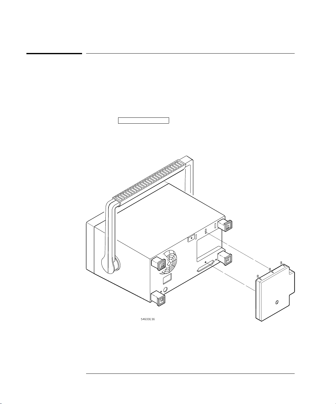
To install the interface module
To install the interface module
1 Turn off the instrument.
2 Install the module as shown below.
The instrument is reset after installation. The installed interface module is
shown in the message displayed when your turn on the instrument. The I/O
functions (controller and hardcopy) are available by pressing the instrument
front-panel
Print/Utilit y key.
Installation of interface module to Agilent 54600-Series instrument
6
Page 7

Interface Cables
I/O Function Guide
To install the interface module
Agilent Interface
module
Cable function
(Instrument to ..)
Module
connector
Printer/plotter/
controller
Agilent
part number
Cable
Length
connector
54650A, 54655A
1
(GPIB)
54657A
54651A, 54656A
1
(RS-232-C)
54658A
1,3
,
1,3
,
Printer/plotter/
controller
GPIB GPIB 10833A
10833B
10833C
0833D
Printer/plotter/
controller
25-pin F 25-pin F 13242G
17255M
Controller 25-pin F 25-pin M 92219J
17255D
1 m (3.3 ft)
2 m (6.6 ft)
4 m (13.2 ft)
0.5 m (1.6 ft)
5 m (16.7 ft)
1.5 m (4.9 ft)
5 m (16.7 ft)
1.5 m (4.9 ft)
Controller 25-pin F 9-pin M 24542G 3 m (9.9 ft)
54652A
(parallel output only)
54652B
2
, 54659B
1,2
Parallel printer parallel parallel C2950A
C2951A
2 m (6.6 ft)
3 m (9.9 ft)
RS-232-C controller 9-pin M 25-pin M 34398A 2.5 m (8.2 ft)
(RS-232-C and parallel
output)
1
The enhanced features of the 54655A/56A/57A/58A/59B are not available to the 54620A/C Logic Analyzer. These modules
supply enhanced oscilloscope programming functions. The I/O functions of these modules will function when used with the
54620A/C Logic Analyzer.
2
The 54652B and 54659B are not compatible with the 54600A, 54601A, 54602A, and 54610A.
3
The 54655A and 54656A are not compatible with the 54615B , 54615B, 54645A and 54645D.
RS-232-C controller 9-pin M 9-pin M 34398A 2.5 m (8.2 ft)
RS-232-C printer/
plotter/controller
Parallel printer parallel parallel C2950A
9-pin M 25-pin F 34398A + 34399A
adapter kit
C2951A
2.5 m (8.2 ft)
2 m (6.6 ft)
3 m (9.9 ft)
7
Page 8

Print
Utility
Print/Utility Menu
Print/Utility Menu
The Print/Utility menu of your Agilent 54600-series instrument allows
you to select I/O functions for the module you have connected to your
instrument. The module can have an GPIB, RS-232-C, parallel, or
combination RS-232-C/parallel interface.
• To display this menu, press Print/Utility .
Print Screen pressing this softkey sends the screen image to your printer or
plotter.
Interface setup
In many cases, the interface will need to be configured before attempting to
print. If you are setting up an GPIB module, refer to "To set GPIB addresses" on
page 17. If you are setting up an RS-232-C module, refer to "To set RS-232 baud
rate and handshake" on page 18.
Hardcopy Menu this softkey allows you to select your printer or plotter type
and to set parameters for that printer or plotter.
I/O Menu this softkey allows you to set up parameters for your RS-232-C or
GPIB interface for printer or controller operation.
Service Menu and System Config these softkeys control instrument and
enhanced module functions such as service self-test, service self-calibration
and system configuration. Refer to your instrument User and Service Guide
or enhanced module User’s Guide for use of these softkeys.
8
Page 9

To select your printer or plotter
• Press the Hardcopy Menu softkey to view printer/plotter options.
Your module can be configured to print in several formats.
• To select the format of your printer/plotter, press the Format softkey
until the desired format is displayed.
Hardcopy Menu with RS-232-C or parallel module attached
I/O Function Guide
To select your printer or plotter.
Format Your module can be configured to print in the following formats:
LaserJet HP LaserJet format
DJ mono monochrome HP DeskJet format
DJ color color HP DeskJet format (color Agilent 54600-series instruments
only)
Epson Epson format
ThinkJet HP ThinkJet format (GPIB and RS-232-C modules only)
Plotter HP plotter (HP-GL) format. This format is available on GPIB and
RS-232-C modules only and is not an option on color Agilent 54600
instruments.
9
Page 10

I/O Function Guide
To select your printer or plotter.
Destination If you have an RS-232-C/parallel dual interface module,
press the Destination softkey to select the hardcopy output destination of
the module to be RS-232 or Parallel.
Hardcopy Menu with RS-232-C/parallel dual interface module attached
Printer address If you have an GPIB interface module, press the PrintAddr
softkey until the correct address is displayed. The address can also be
incremented or decremented by turning the knob closest to the
key. The default printer/plotter address is 1.
Cursors
Hardcopy Menu with GPIB module attached
10
Page 11

To setup your printer or plotter
• From the Hardcopy Menu, press the Printer Setup softkey.
Selecting Printer Setup from the Hardcopy Menu
Printer/plotter options are displayed for formfeed, scale factors, and gray
scale printing.
I/O Function Guide
To setup your printer or plotter
Printer setup options for Agilent LaserJet and Agilent DeskJet formats
11
Page 12

I/O Function Guide
To set formfeed
To set formfeed
• To set formfeed, press the Hardcopy Menu softkey, then the Printer Setup
softkey. Formfeed can be selected as On or Off
The instrument will send a formfeed command after printing when Formfeed
is set to On.
Formfeed is not an option when Format is set to Plotter.
12
Page 13

To print or plot gray scale
Gray scale printing
• To print in gray scale, press the Hardcopy Menu softkey, then the Printer
softkey. GrayScale can be selected as On or Off
Setup
Selecting GrayScale from the Printer Setup menu
When gray scale printing is selected, the full-bright and half-bright traces on
the instrument screen are printed on the hardcopy.
I/O Function Guide
To print or plot gray scale
Gray scale printing requires an HP-PCL printer capable of at least 300 dpi
(dots-per-inch), such as an HP LaserJet or HP DeskJet series printer. Grayscale
printing is not available with ThinkJet and Epson formats. If you have a color
Agilent 54600-series instrument, DJ Color format will print in 2 different colors.
Gray scale print
13
Page 14

I/O Function Guide
To print or plot gray scale
Gray scale plotting
1 Press the Hardcopy Menu softkey, then press the Format softkey until
Plotter is displayed.
Plotting GrayScale from the Plotter Setup menu
Gray scale plotting requires an HP-GL plotter capable of plotting with at least 2
pens.
2
Press the Plotter Setup softkey, then press the Colors softkey until 2 is
displayed.
Gray scale plot uses two pens for the hardcopy. Half-bright traces are plotted
with plotter pen 1 and full-bright traces are plotted with plotter pen 2.
14
Page 15

I/O Function Guide
To print or plot scale factors
To print or plot scale factors
Instrument scale factors may be turned on or off for hardcopy prints and
plots. All factors are printed on the hardcopy when on is selected. When
factors is selected for a hardcopy plot, the plot is in portrait mode. When
factors is not selected for hardcopy plot, the plot is in landscape mode.
1
Press the Hardcopy Menu softkey, then press the Printer Setup softkey.
2 Press the Factors softkey until On is displayed.
Print or Plot with Factors On (portrait mode)
15
Page 16

I/O Function Guide
To print or plot scale factors
Plot with Factors Off (landscape mode)
16
Page 17

Setting GPIB addresses
I/O Function Guide
To set GPIB addresses
To set GPIB addresses
To set addresses on GPIB modules, press Prin t/ Utility , then press
•
the I/O Menu softkey.
This menu allows you to set the instrument and printer/plotter address.
Each device on an GPIB bus must have a unique instrument adresss between
0 and 30.
Instrument address
To set the instrument address, press the InstAddr softkey until the correct
address is displayed. The address can also be incremented or decremented
by turning the knob closest to the
address is 7.
Cursors key. The default instrument
Printer Address
To set the printer or plotter address on the GPIB bus, press the PrintAddr
softkey until the correct address is displayed. The address can also be
incremented or decremented by turning the knob closest to the
Cursor s key. The default printer/plotter address is 1.
See also For more information on GPIB parameters, refer to the Programmer’s Guide
that came with your Agilent 54600-Series instrument.
17
Page 18

I/O Function Guide
To set RS-232 baud rate and handshake
To set RS-232 baud rate and handshake
To set the baud rate and handshake parameters on a module with an
•
RS-232 interface, press
softkey.
Setting RS-232-C baud rate and handshake
Print/ Ut il ity , then press the I/O Menu
Baud rate
To set the RS-232 baud rate, press the Baud Rate softkey until the correct
value is displayed. The baud rate can also be incremented or decremented
by turning the knob closest to the
selected as 1200, 2400, 9600, or 19200. The default baud rate is 9600.
Cursors key. The baud rate can be
Handshake
To set the RS-232 handshake protocol, press the Handshake softkey until the
correct protocol is displayed.
Handshake can be set to DTR (data terminal ready) or XON (XON-transmit on
/XOFF-transmit off.)
See also For more information on RS-232 parameters, refer to the Programmer’s
Guide that came with your Agilent 54600-Series instrument.
18
Page 19

DECLARATION OF CONFORMITY
according to ISO/IEC Guide 22 and EN 45014
Manufacturer’s Name:
Manufacturer’s Address:
Agilent Technologies
1900 Garden of the Gods Road
Colorado Springs , CO 80901 USA
Declares, That the product
Product Name:
Model Number(s):
Product Options:
Digitizing Oscilloscope Module
54652B and 54659B
All
Conforms to the following Product Specifications:
Safety:
IEC 1010-1:1990 +A1 / EN 61010-1:1993
UL 3111
CSA-C22.2 No. 1010.1:1993
EMC:
CISPR 11:1990 /EN 55011 (1991): Group 1 Class A
IEC 555-2:1982 + A1:1985 / EN 60555-2:1987
IEC 555-3:1982 + A1:1990 / EN 60555-3:1983 + A1:1991
IEC 801-2:1991/EN 50082-1 (1992):4 kV CD, 8 kV AD
IEC 801-3:1984/EN 50082-1 (1992):3 V/m, {1kHz 80% AM,27-1000MHz}
IEC 801-4:1988/EN 50082-1 (1992): 0.5 kV Sig. Lines, 1kV Power Lines
Supplementary Information:
The product herewith complies with the requirements of the Low Voltage
Directive 73/23/EEC and the EMC Directive 89/336/EEC, and carries the CE-marking
accordingly.
This product was tested in a typical configuration with Agilent Technologies test
systems.
Colorado Springs, 1/12/95
John Strathman, Quality Manager
European Contact: Your local Agilent Technologies Sales and Service Office or Agilent Technologies GmbH, Department ZQ /
Standards Europe, Herrenberger Strasse 130, 71034 Böblingen Germany (FAX: +49-7031-143143)
Page 20

DECLARATION OF CONFORMITY
according to ISO/IEC Guide 22 and EN 45014
Manufacturer’s Name:
Manufacturer’s Address:
Agilent Technologies
1900 Garden of the Gods Road
Colorado Springs , CO 80901 USA
Declares, That the product
Product Name:
Model Number(s):
Product Options:
Digitizing Oscilloscope Module
54655A and 54656A
All
Conforms to the following Product Specifications:
Safety:
IEC 1010-1:1990 +A1 / EN 61010-1:1993
UL 3111
CSA-C22.2 No. 1010.1:1993
EMC:
CISPR 11:1990 /EN 55011 (1991): Group 1 Class A
IEC 555-2:1982 + A1:1985 / EN 60555-2:1987
IEC 555-3:1982 + A1:1990 / EN 60555-3:1983 + A1:1991
IEC 801-2:1991/EN 50082-1 (1992):4 kV CD, 8 kV AD
IEC 801-3:1984/EN 50082-1 (1992):3 V/m, {1kHz 80% AM,27-1000MHz}
IEC 801-4:1988/EN 50082-1 (1992): 0.5 kV Sig. Lines, 1kV Power Lines
Supplementary Information:
The product herewith complies with the requirements of the Low Voltage
Directive 73/23/EEC and the EMC Directive 89/336/EEC, and carries the CE-marking
accordingly.
This product was tested in a typical configuration with Agilent Technologies test
systems.
Colorado Springs, 1/14/97
John Strathman, Quality Manager
European Contact: Your local Agilent Technologies Sales and Service Office or Agilent Technologies GmbH, Department ZQ /
Standards Europe, Herrenberger Strasse 130, 71034 Böblingen Germany (FAX: +49-7031-143143)
Page 21

DECLARATION OF CONFORMITY
according to ISO/IEC Guide 22 and EN 45014
Manufacturer’s Name:
Manufacturer’s Address:
Agilent Technologies
1900 Garden of the Gods Road
Colorado Springs , CO 80901 USA
Declares, That the product
Product Name:
Model Number(s):
Product Options:
Digitizing Oscilloscope Module
54657A and 54658A
All
Conforms to the following Product Specifications:
Safety:
IEC 1010-1:1990 +A1 / EN 61010-1:1993
UL 3111
CSA-C22.2 No. 1010.1:1993
EMC:
CISPR 11:1990 /EN 55011 (1991): Group 1 Class A
IEC 555-2:1982 + A1:1985 / EN 60555-2:1987
IEC 555-3:1982 + A1:1990 / EN 60555-3:1983 + A1:1991
IEC 801-2:1991/EN 50082-1 (1992):4 kV CD, 8 kV AD
IEC 801-3:1984/EN 50082-1 (1992):3 V/m, {1kHz 80% AM,27-1000MHz}
IEC 801-4:1988/EN 50082-1 (1992): 0.5 kV Sig. Lines, 1kV Power Lines
Supplementary Information:
The product herewith complies with the requirements of the Low Voltage
Directive 73/23/EEC and the EMC Directive 89/336/EEC, and carries the CE-marking
accordingly.
This product was tested in a typical configuration with Agilent Technologies test
systems.
Colorado Springs, 4/24/97
John Strathman, Quality Manager
European Contact: Your local Agilent Technologies Sales and Service Office or Agilent Technologies GmbH, Department ZQ /
Standards Europe, Herrenberger Strasse 130, 71034 Böblingen Germany (FAX: +49-7031-143143)
Page 22

Page 23

Copyright Agilent
Technologies 1991-1996, 2000
All Rights Reserved.
Reproduction, adaptation, or
translation without prior
written permission is
prohibited, except as allowed
under the copyright laws.
Document Warranty
The information contained in
this document is subject to
change without notice.
Agilent Technologies
makes no warranty of any
kind with regard to this
material, including, but
not limited to, the implied
warranties or
merchantability and
fitness for a particular
purpose.
Agilent Technologies shall
not be liable for errors
contained herein or for
incidental or consequential
damages in connection with
the furnishing, performance,
or use of this material.
Complete product warranty
information is given at the
end of this manual.
Safety
This apparatus has been
designed and tested in
accordance with IEC
Publication 348, Safety
Requirements for Measuring
Apparatus, and has been
supplied in a safe condition.
This is a Safety Class I
instrument (provided with
terminal for protective
earthing). Before applying
power, verify that the correct
safety precautions are taken
(see the following warnings).
In addition, note the external
markings on the instrument
that are described under
"Safety Symbols."
Warning
• Before turning on the
instrument, you must connect
the protective earth terminal
of the instrument to the
protective conductor of the
(mains) power cord. The
mains plug shall only be
inserted in a socket outlet
provided with a protective
earth contact. You must not
negate the protective action
by using an extension cord
(power cable) without a
protective conductor
(grounding). Grounding one
conductor of a two-conductor
outlet is not sufficient
protection.
• Only fuses with the
required rated current,
voltage, and specified type
(normal blow, time delay,
etc.) should be used. Do not
use repaired fuses or
short-circuited fuseholders.
To do so could cause a shock
of fire hazard.
• Service instructions are for
trained service personnel. To
avoid dangerous electric
shock, do not perform any
service unless qualified to do
so. Do not attempt internal
service or adjustment unless
another person, capable of
rendering first aid and
resuscitation, is present.
• If you energize this
instrument by an auto
transformer (for voltage
reduction), make sure the
common terminal is
connected to the earth
terminal of the power source.
• Whenever it is likely that
the ground protection is
impaired, you must make the
instrument inoperative and
secure it against any
unintended operation.
• Do not operate the
instrument in the presence of
flammable gasses or fumes.
Operation of any electrical
instrument in such an
environment constitutes a
definite safety hazard.
• Do not install substitute
parts or perform any
unauthorized modification to
the instrument.
• Capacitors inside the
instrument may retain a
charge even if the instrument
is disconnected from its
source of supply.
• Use caution when exposing
or handling the CRT.
Handling or replacing the
CRT shall be done only by
qualified maintenance
personnel.
Safety Symbols
Instruction manual symbol:
the product is marked with
this symbol when it is
necessary for you to refer to
the instruction manual in
order to protect against
damage to the product.
Hazardous voltage symbol.
Earth terminal symbol: Used
to indicate a circuit common
connected to grounded
chassis.
WARNING
The Warning sign denotes a
hazard. It calls attention to a
procedure, practice, or the
like, which, if not correctly
performed or adhered to,
could result in personal
injury. Do not proceed
beyond a Warning sign until
the indicated conditions are
fully understood and met.
CAUTION
The Caution sign denotes a
hazard. It calls attention to
an operating procedure,
practice, or the like, which, if
not correctly performed or
adhered to, could result in
damage to or destruction of
part or all of the product. Do
not proceed beyond a
Caution symbol until the
indicated conditions are fully
understood or met.
Agilent Technologies
P.O. Box 2197
1900 Garden of the Gods Road
Colorado Springs, CO 80901
Page 24

Product Warranty
This Agilent Technologies
product has a warranty
against defects in material
and workmanship for a period
of three years from date of
shipment. During the
warranty period, Agilent
Technologies will, at its
option, either repair or
replace products that prove
to be defective.
For warranty service or
repair, this product must be
returned to a service facility
designated by Agilent
Technologies.
For products returned to
Agilent Technologies for
warranty service, the Buyer
shall prepay shipping charges
to Agilent Technologies and
Agilent Technologies shall
pay shipping charges to
return the product to the
Buyer. However, the Buyer
shall pay all shipping charges,
duties, and taxes for products
returned to Agilent
Technologies from another
country.
Agilent Technologies
warrants that its software and
firmware designated by
Agilent Technologies for use
with an instrument will
execute its programming
instructions when properly
installed on that instrument.
Agilent Technologies does
not warrant that the
operation of the instrument
software, or firmware will be
uninterrupted or error free.
Limitation of Warranty
The foregoing warranty shall
not apply to defects resulting
from improper or inadequate
maintenance by the Buyer,
Buyer-supplied software or
interfacing, unauthorized
modification or misuse,
operation outside of the
environmental specifications
for the product, or improper
site preparation or
maintenance.
No other warranty is
expressed or implied. Agilent
Technologies specifically
disclaims the implied
warranties or merchantability
and fitness for a particular
purpose.
Exclusive Remedies
The remedies provided herein
are the buyer’s sole and
exclusive remedies. Agilent
Technologies shall not be
liable for any direct, indirect,
special, incidental, or
consequential damages,
whether based on contract,
tort, or any other legal theory.
Assistance
Product maintenance
agreements and other
customer assistance
agreements are available for
Agilent Technologies
products.
For any assistance, contact
your nearest Agilent
Technologies Sales Office.
Certification
Agilent Technologies certifies
that this product met its
published specifications at
the time of shipment from the
factory. Agilent Technologies
further certifies that its
calibration measurements are
traceable to the United States
National Institute of
Standards and Technology, to
the extent allowed by the
Institute’s calibration facility,
and to the calibration
facilities of other
International Standards
Organization members.
About this edition
This is the the Interface
Modules for Agilent
54600-Series Instruments
I/O Function Guide.
Publication number
54652-97004
Printed in USA.
Edition dates are as follows:
54652-97004, August 2000
54652-97002, July 1996
New editions are complete
revisions of the manual.
Update packages, which are
issued between editions,
contain additional and
replacement pages to be
merged into the manual by
you. The dates on the title
page change only when a new
edition is published.
 Loading...