

Page 1

HP Integrity NonStop BladeSystem Planning Guide
HP Part Number: 545740-002
Published: May 2008
Edition: J06.03 and subsequent J-series RVUs
Page 2

© Copyright 2008 Hewlett-Packard Development Company, L.P.
Legal Notice
Confidential computersoftware. Valid license from HP required for possession, use or copying. Consistent with FAR 12.211 and12.212, Commercial
Computer Software, Computer Software Documentation, and Technical Data for Commercial Items are licensed to the U.S. Government under
vendor’s standard commercial license.
The informationcontained hereinis subject to change without notice. Theonly warranties for HP products and services are setforth inthe express
warranty statements accompanying such products and services. Nothing herein should be construed as constituting an additional warranty. HP
shall not be liable for technical or editorial errors or omissions contained herein.
Export of the information contained in this publication may require authorization from the U.S. Department of Commerce.
Microsoft, Windows, and Windows NT are U.S. registered trademarks of Microsoft Corporation.
Intel, Pentium, and Celeron are trademarks or registered trademarks of Intel Corporation or its subsidiaries in the United States and other
countries.
Java is a U.S. trademark of Sun Microsystems, Inc.
Motif, OSF/1, UNIX, X/Open, and the "X" device are registered trademarks, and IT DialTone and The Open Group are trademarks of The Open
Group in the U.S. and other countries.
Open Software Foundation, OSF, the OSF logo, OSF/1, OSF/Motif, and Motif are trademarks of the Open Software Foundation, Inc.
OSF MAKES NO WARRANTY OF ANY KIND WITH REGARD TO THE OSF MATERIAL PROVIDED HEREIN, INCLUDING, BUT NOT
LIMITED TO, THE IMPLIED WARRANTIES OF MERCHANTABILITY AND FITNESS FOR A PARTICULAR PURPOSE.
OSF shall not be liable for errors contained herein or for incidental consequential damages in connection with the furnishing, performance, or
use of this material.
© 1990, 1991, 1992, 1993 Open Software Foundation, Inc. The OSF documentation and the OSF software to which it relates are derived in part
from materials supplied by the following:
© 1987, 1988, 1989 Carnegie-Mellon University. © 1989, 1990, 1991 Digital Equipment Corporation. © 1985, 1988, 1989, 1990 Encore Computer
Corporation. © 1988 Free Software Foundation, Inc. © 1987, 1988, 1989, 1990, 1991 Hewlett-Packard Company. © 1985, 1987, 1988, 1989, 1990,
1991, 1992 International Business Machines Corporation. © 1988, 1989 Massachusetts Institute of Technology. © 1988, 1989, 1990 Mentat Inc. ©
1988 Microsoft Corporation. © 1987, 1988, 1989, 1990, 1991, 1992 SecureWare, Inc. © 1990, 1991 Siemens Nixdorf Informationssysteme AG. ©
1986, 1989, 1996, 1997 Sun Microsystems, Inc. © 1989, 1990, 1991 Transarc Corporation.
OSF software and documentation arebased inpart on the Fourth BerkeleySoftware Distribution under license fromThe Regents of the University
of California. OSF acknowledges the following individuals and institutions for their role in its development: Kenneth C.R.C. Arnold, Gregory S.
Couch, Conrad C. Huang, Ed James, Symmetric Computer Systems, Robert Elz. © 1980, 1981, 1982, 1983, 1985, 1986, 1987, 1988, 1989 Regents of
the University of California.
Page 3

Table of Contents
About This Document.......................................................................................................11
Supported Release Version Updates (RVUs)........................................................................................11
Intended Audience................................................................................................................................11
New and Changed Information in This Edition...................................................................................11
Document Organization.......................................................................................................................11
Notation Conventions...........................................................................................................................11
General Syntax Notation.................................................................................................................11
Publishing History................................................................................................................................13
HP Encourages Your Comments..........................................................................................................14
1 NonStop BladeSystem Overview................................................................................15
NonStop NB50000c BladeSystem..........................................................................................................15
NonStop Multicore Architecture (NSMA)......................................................................................16
NonStop NB50000c BladeSystem Hardware.............................................................................17
c7000 Enclosure.....................................................................................................................17
NonStop Server Blade...........................................................................................................19
IP CLuster I/O Module (CLIM).............................................................................................19
Storage CLuster I/O Module (CLIM)....................................................................................19
SAS Disk Enclosure ..............................................................................................................20
IOAM Enclosure...................................................................................................................20
Fibre Channel Disk Module (FCDM)...................................................................................20
Maintenance Switch..............................................................................................................20
BladeSystem Connections to Maintenance Switch...............................................................21
CLIM Connections to Maintenance Switch..........................................................................21
IOAM Enclosure Connections to Maintenance Switch........................................................21
System Console.....................................................................................................................21
UPS and ERM (Optional)......................................................................................................21
Enterprise Storage System (Optional)..................................................................................22
Tape Drive and Interface Hardware (Optional)....................................................................23
Preparation for Other Server Hardware...............................................................................................23
Management Tools for NonStop BladeSystems ...................................................................................23
OSM Package...................................................................................................................................24
Onboard Administrator (OA)..........................................................................................................24
Integrated Lights Out (iLO).............................................................................................................24
Cluster I/O Protocols (CIP) Subsystem............................................................................................24
Subsystem Control Facility (SCF) Subsystem.................................................................................24
Component Location and Identification...............................................................................................24
Terminology.....................................................................................................................................25
Rack and Offset Physical Location..................................................................................................26
ServerNet Switch Group-Module-Slot Numbering........................................................................26
NonStop Server Blade Group-Module-Slot Numbering.................................................................27
CLIM Enclosure Group-Module-Slot-Port-Fiber Numbering.........................................................27
IOAM Enclosure Group-Module-Slot Numbering.........................................................................27
Fibre Channel Disk Module Group-Module-Slot Numbering........................................................29
System Installation Document Packet..................................................................................................30
Technical Document for the Factory-Installed Hardware Configuration.......................................30
Configuration Forms for the ServerNet Adapters and CLIMs.......................................................30
2 Site Preparation Guidelines........................................................................................31
Table of Contents 3
Page 4

Modular Cabinet Power and I/O Cable Entry......................................................................................31
Emergency Power-Off Switches...........................................................................................................31
EPO Requirement for NonStop BladeSystems................................................................................31
EPO Requirement for HP R12000/3 UPS.........................................................................................31
Electrical Power and Grounding Quality.............................................................................................31
Power Quality..................................................................................................................................31
Grounding Systems.........................................................................................................................32
Power Consumption........................................................................................................................32
Uninterruptible Power Supply (UPS)...................................................................................................32
Cooling and Humidity Control............................................................................................................33
Weight...................................................................................................................................................34
Flooring.................................................................................................................................................34
Dust and Pollution Control...................................................................................................................34
Zinc Particulates....................................................................................................................................34
Space for Receiving and Unpacking the System..................................................................................34
Operational Space.................................................................................................................................35
3 System Installation Specifications...............................................................................37
Modular Cabinets.................................................................................................................................37
NonStop BladeSystem Power Distribution...........................................................................................37
Power Feed Setup for the NonStop BladeSystem...........................................................................38
North America/Japan Power Setup With Rack-Mounted UPS.......................................................38
North America/Japan Power Setup Without Rack-Mounted UPS..................................................39
International Power Setup With Rack-Mounted UPS.....................................................................40
International Power Setup Without Rack-Mounted UPS................................................................41
Power Distribution Units (PDUs).........................................................................................................42
AC Input Power for Modular Cabinets................................................................................................44
North America and Japan: 208 V AC PDU Power..........................................................................44
International: 400 V AC PDU Power...............................................................................................44
Branch Circuits and Circuit Breakers..............................................................................................44
Enclosure AC Input.........................................................................................................................45
Phase Load Balancing......................................................................................................................45
Enclosure Power Loads...................................................................................................................46
Dimensions and Weights......................................................................................................................47
Plan View of the 42U Modular Cabinet...........................................................................................47
Service Clearances for the Modular Cabinets.................................................................................47
Unit Sizes.........................................................................................................................................47
42U Modular Cabinet Physical Specifications.................................................................................48
Enclosure Dimensions.....................................................................................................................48
Modular Cabinet and Enclosure Weights With Worksheet ...........................................................49
Modular Cabinet Stability.....................................................................................................................49
Environmental Specifications...............................................................................................................50
Heat Dissipation Specifications and Worksheet..............................................................................50
Operating Temperature, Humidity, and Altitude...........................................................................50
Nonoperating Temperature, Humidity, and Altitude.....................................................................51
Cooling Airflow Direction...............................................................................................................51
Blanking Panels................................................................................................................................51
Typical Acoustic Noise Emissions...................................................................................................51
Tested Electrostatic Immunity.........................................................................................................51
Calculating Specifications for Enclosure Combinations.......................................................................51
4 System Configuration Guidelines...............................................................................53
Internal ServerNet Interconnect Cabling..............................................................................................53
4 Table of Contents
Page 5

Dedicated Service LAN Cables........................................................................................................53
Length Restrictions for Optional Cables.........................................................................................53
Cable Product IDs............................................................................................................................54
ServerNet Fabric and Supported Connections.....................................................................................54
ServerNet Cluster Connections ......................................................................................................54
ServerNet Fabric Cross-Link Connections......................................................................................55
Interconnections Between c7000 Enclosures...................................................................................55
I/O Connections (Standard and High I/O ServerNet Switch Configurations)................................55
Connections to IOAM Enclosures...................................................................................................56
Connections to CLIMs.....................................................................................................................56
NonStop BladeSystem Port Connections..............................................................................................56
Fibre Channel Ports to Fibre Channel Disk Modules......................................................................56
Fibre Channel Ports to Fibre Tape Devices......................................................................................57
SAS Ports to SAS Disk Enclosures...................................................................................................57
SAS Ports to SAS Tape Devices........................................................................................................57
Storage CLIM Devices...........................................................................................................................57
Factory-Default Disk Volume Locations for SAS Disk Devices......................................................58
Configuration Restrictions for Storage CLIMs................................................................................58
Configurations for Storage CLIM and SAS Disk Enclosures..........................................................58
Two Storage CLIMs, Two SAS Disk Enclosures.........................................................................58
Two Storage CLIMs, Four SAS Disk Enclosures........................................................................59
Fibre Channel Devices..........................................................................................................................60
Factory-Default Disk Volume Locations for FCDMs......................................................................61
Configurations for Fibre Channel Devices......................................................................................62
Configuration Restrictions for Fibre Channel Devices....................................................................62
Recommendations for Fibre Channel Device Configuration..........................................................62
Example Configurations of the IOAM Enclosure and Fibre Channel Disk Module......................63
Two FCSAs, Two FCDMs, One IOAM Enclosure......................................................................64
Four FCSAs, Four FCDMs, One IOAM Enclosure.....................................................................64
Two FCSAs, Two FCDMs, Two IOAM Enclosures....................................................................65
Four FCSAs, Four FCDMs, Two IOAM Enclosures...................................................................66
Daisy-Chain Configurations......................................................................................................67
Four FCSAs, Three FCDMs, One IOAM Enclosure...................................................................69
Ethernet to Networks............................................................................................................................70
Managing NonStop BladeSystem Resources........................................................................................71
Changing Customer Passwords......................................................................................................71
Change the Onboard Administrator (OA) Password................................................................72
Change the CLIM iLO Password...............................................................................................72
Change the Maintenance Interface (Eth0) Password ................................................................72
Change the NonStop ServerBlade MP (iLO) Password.............................................................73
Change the Remote Desktop Password.....................................................................................73
Default Naming Conventions..........................................................................................................73
Possible Values of Disk and Tape LUNs..........................................................................................75
5 Hardware Configuration in Modular Cabinets.........................................................77
Maximum Number of Modular Components......................................................................................77
Enclosure Locations in Cabinets...........................................................................................................77
Typical Configuration...........................................................................................................................78
6 Maintenance and Support Connectivity....................................................................81
Dedicated Service LAN.........................................................................................................................81
Basic LAN Configuration................................................................................................................81
Fault-Tolerant LAN Configuration .................................................................................................83
Table of Contents 5
Page 6

IP Addresses....................................................................................................................................84
Ethernet Cables................................................................................................................................88
SWAN Concentrator Restrictions....................................................................................................88
Dedicated Service LAN Links Using G4SAs...................................................................................88
Dedicated Service LAN Links Using IP CLIMs..............................................................................89
Initial Configuration for a Dedicated Service LAN.........................................................................89
System Consoles...................................................................................................................................89
System Console Configurations......................................................................................................90
One System Console Managing One System (Setup Configuration)........................................90
Primary and Backup System Consoles Managing One System.................................................90
Multiple System Consoles Managing One System....................................................................91
Managing Multiple Systems Using One or Two System Consoles............................................91
Cascading Ethernet Switch or Hub Configuration....................................................................91
A Cables...........................................................................................................................93
Cable Types, Connectors, Lengths, and Product IDs...........................................................................93
Cable Length Restrictions.....................................................................................................................94
B Operations and Management Using OSM Applications........................................95
System-Down OSM Low-Level Link....................................................................................................95
AC Power Monitoring...........................................................................................................................95
AC Power-Fail States............................................................................................................................97
C Default Startup Characteristics...................................................................................99
Index...............................................................................................................................103
6 Table of Contents
Page 7

List of Figures
1-1 Example of a NonStop NB50000c BladeSystem............................................................................16
1-2 c7000 Enclosure Features...............................................................................................................18
1-3 Connections Between Storage CLIMs and ESS.............................................................................23
3-1 North America/Japan 3-Phase Power Setup With Rack-Mounted UPS........................................39
3-2 North America/Japan Power Setup...............................................................................................40
3-3 International 3-Phase Power Setup With UPS...............................................................................41
3-4 International Power Setup Without Rack-Mounted UPS..............................................................42
3-5 Bottom AC Power Feed.................................................................................................................43
3-6 Top AC Power Feed.......................................................................................................................43
4-1 ServerNet Switch Standard I/O Supported Connections .............................................................55
4-2 ServerNet Switch High I/O Supported Connections ...................................................................56
4-3 Two Storage CLIMs, Two SAS Disk Enclosure Configuration.....................................................59
4-4 Two Storage CLIMs, Four SAS Disk Enclosure Configuration.....................................................60
5-1 42U Configuration.........................................................................................................................79
6-1 Example of a Basic LAN Configuration With One Maintenance Switch......................................82
6-2 Example of a Fault-Tolerant LAN Configuration With Two Maintenance Switches...................84
7
Page 8

8
Page 9

List of Tables
3-1 Example of Cabinet Load Calculations.........................................................................................52
4-1 Default User Names and Passwords.............................................................................................72
9
Page 10

10
Page 11

About This Document
This guide describes the HP Integrity NonStop™ BladeSystem and provides examples of system
configurations toassist you in planning forinstallation of a new HP Integrity NonStop™ NB50000c
BladeSystem.
Supported Release Version Updates (RVUs)
This publication supports J06.03 and all subsequent J-series RVUs until otherwise indicated in
a replacement publication.
Intended Audience
This guide is written for those responsible for planning the installation, configuration, and
maintenance of a NonStop BladeSystem and the software environment at a particular site.
Appropriate personnelmust have completed HP training courses on system support for NonStop
BladeSystems.
New and Changed Information in This Edition
This is a new manual.
Document Organization
Chapter 1 (page 15)
Chapter 2 (page 31)
Chapter 3 (page 37)
Chapter 4 (page 53)
Chapter 5 (page 77)
Chapter 6 (page 81)
Appendix A (page 93)
Appendix B (page 95)
Appendix C (page 99)
ContentsSection
This chapter provides an overview of the Integrity
NonStop NB50000c BladeSystem.
This chapter outlines topics to consider when planning
or upgrading the installation site.
This chapter provides the installation specifications for a
fully populated NonStop BladeSystem enclosure.
This chapter describes the guidelines for implementing
the NonStop BladeSystem.
This chaptershows recommended locations for hardware
enclosures in the NonStop BladeSystem.
This chapter describes the connectivity options, including
ISEE, for maintenance and support of a NonStop
BladeSystem.
This appendix identifies the cables used with the NonStop
BladeSystem hardware.
This appendix describes how to use the OSM applications
to manage a NonStop BladeSystem.
This appendix describes the default startup characteristics
for a NonStop BladeSystem.
Notation Conventions
General Syntax Notation
This list summarizes the notation conventions for syntax presentation in this manual.
Supported Release Version Updates (RVUs) 11
Page 12

UPPERCASE LETTERS Uppercase letters indicate keywords and reserved words. Type these
items exactly as shown. Items not enclosed in brackets are required.
For example:
MAXATTACH
Italic Letters
Italic letters, regardless of font, indicate variable items that you
supply. Items not enclosed in brackets are required. For example:
file-name
Computer Type
Computer type letters indicate:
• C and Open System Services (OSS) keywords, commands, and
reserved words. Type these items exactly as shown. Items not
enclosed in brackets are required. For example:
Use the cextdecs.h header file.
• Text displayed by the computer. For example:
Last Logon: 14 May 2006, 08:02:23
• A listing of computer code. For example
if (listen(sock, 1) < 0)
{
perror("Listen Error");
exit(-1);
}
Bold Text
Bold text in an example indicates user input typed at the terminal.
For example:
ENTER RUN CODE
?123
CODE RECEIVED: 123.00
The user must press the Return key after typing the input.
[ ] Brackets Brackets enclose optional syntax items. For example:
TERM [\system-name.]$terminal-name
INT[ERRUPTS]
A group of items enclosed in brackets is a list from which you can
choose one item or none. The items in the list can be arranged either
vertically, with aligned brackets on each side of the list, or
horizontally, enclosed in a pair of brackets and separated by vertical
lines. For example:
FC [ num ]
[ -num ]
[ text ]
12
K [ X | D ] address
{ } Braces A group of items enclosed in braces is a list from which you are
required to choose one item. The items in the list can be arranged
either vertically, with aligned braces on each side of the list, or
horizontally, enclosed in a pair of braces and separated by vertical
lines. For example:
LISTOPENS PROCESS { $appl-mgr-name }
{ $process-name }
ALLOWSU { ON | OFF }
Page 13

| Vertical Line A vertical line separates alternatives in a horizontal list that is enclosed
in brackets or braces. For example:
INSPECT { OFF | ON | SAVEABEND }
… Ellipsis An ellipsis immediately following a pair of brackets orbraces indicates
that you can repeat the enclosed sequence of syntax items any number
of times. For example:
M address [ , new-value ]…
- ] {0|1|2|3|4|5|6|7|8|9}…
An ellipsis immediately following a single syntax item indicates that
you can repeat that syntax item any number of times. For example:
"s-char…"
Punctuation Parentheses, commas, semicolons, and other symbols not previously
described must be typed as shown. For example:
error := NEXTFILENAME ( file-name ) ;
LISTOPENS SU $process-name.#su-name
Quotation marks around a symbol such as a bracket or braceindicate
the symbol is a required character that you must type as shown. For
example:
Item Spacing Spaces shown between items are required unless one of the items is
Line Spacing If the syntax of a command is too long to fit on a single line, each
Publishing History
"[" repetition-constant-list "]"
a punctuation symbol such as a parenthesis or a comma. For example:
CALL STEPMOM ( process-id ) ;
If there is no space between two items, spaces are not permitted. In
this example, no spaces are permitted between the period and any
other items:
$process-name.#su-name
continuation line is indented three spaces and is separated from the
preceding line by a blank line. This spacing distinguishes items in a
continuation line from items in a vertical list of selections. For
example:
ALTER [ / OUT file-spec / ] LINE
[ , attribute-spec ]…
Publication DateProduct VersionPart Number
May 2008N.A.545740-002
Publishing History 13
Page 14

HP Encourages Your Comments
HP encourages your comments concerning this document. We are committed to providing
documentation that meets your needs. Send any errors found, suggestions for improvement, or
compliments to:
pubs.comments@hp.com
Include the document title, part number, and any comment, error found, or suggestion for
improvement you have concerning this document.
14
Page 15

1 NonStop BladeSystem Overview
NOTE: This document describes products and features that are not yet available on systems
running J-series RVUs. These products and features include:
• CLuster I/O Modules (CLIMs)
• The Cluster I/O Protocols (CIP) subsystem
• Serial attached SCSI (SAS) disk drives and their enclosures
The Integrity NonStop BladeSystem provides an integrated infrastructure with consolidated
server, network, storage, power, and management capabilities. The NonStop BladeSystem
implements the BladeSystem c-Class architecture and is optimized for enterprise data center
applications. The NonStop NB50000c BladeSystem is introduced as part of the J06.03 RVU.
NonStop NB50000c BladeSystem
The NonStop NB50000c BladeSystem combines the NonStop operating system and HP Integrity
NonStop BL860c Server Blades in a single footprint as part of the “NonStop Multicore Architecture
(NSMA)” (page 16).
The characteristics of an Integrity NonStop NB50000c BladeSystem are:
Intel ItaniumProcessor
Chassis
Blade System with 16 processors
Minimum CLIMs
IOAM enclosure
Maximum IOAM enclosures
1
NSE-MProcessor model
c7000 enclosure (one enclosure for 2 to 8 processors; two
enclosures for 10 to 16 processors)
42U, 19 inch rackCabinet
8 GB to 48 GBMinimum/maximum mainmemory perlogical processor
2 to 16Minimum/maximum processors
2, 4, 6, 8, 10, 12, 14, or 16Supported processor configurations
24 CLIMs (IP and Storage)Maximum CLuster I/O Modules (CLIMs) in a NonStop
• 0 CLIMs (if there are IOAM enclosures)
• 2 Storage CLIMs and 2 IP CLIMs (ifthere are no IOAM
enclosures)
4Maximum SAS disk enclosures per Storage CLIM pair
100Maximum SAS disk drives per Storage CLIM pair
4 FCDMsdaisy-chained with 14 disk drives in each FCDMMaximum FibreChannel diskmodules (FCDMs)through
• 6 IOAMs for 10 to 16 processors
• 4 IOAMs for 2 to 8 processors
SupportedEnterprise StorageSystem (ESS) support availablethrough
Storage CLIMs or IOAM enclosures
SupportedConnection to NonStop ServerNet Clusters
Not supportedM8201R Fibre Channel to SCSI router support
Not supportedConnection to NonStop S-series I/O
1 When CLIMs are also included in the configuration, the maximum number of IOAMs might be smaller. Check with
your HP representative to determine your system's maximum for IOAMs.
NonStop NB50000c BladeSystem 15
Page 16
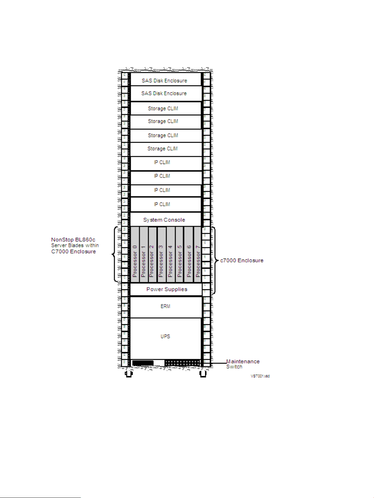
Figure 1-1 “Example of a NonStop NB50000c BladeSystem” shows the front view of an example
NonStop NB50000c BladeSystem with eight server blades in a 42U modular cabinet with the
optional HP R12000/3 UPS and the HP AF434A extended runtime module (ERM).
Figure 1-1 Example of a NonStop NB50000c BladeSystem
NonStop Multicore Architecture (NSMA)
The NonStop BladeSystem employs the HP NonStop Multicore Architecture (NSMA) to achieve
full software fault tolerance by running the NonStop operating system on NonStop Server Blades.
With the NSMA's multiple core microprocessor architecture, a set of cores comprised of instruction
processing units (IPUs) share the same memory map (except in low-level software). The NSMA
extends the traditional NonStop logical processor to a multiprocessor and includes:
• No hardware lockstep checking
• Itanium fault detection
16 NonStop BladeSystem Overview
Page 17

• High-end scalability
• Application virtualization
• Cluster programming transparency
The NonStop NB50000c BladeSystem can be configured with 2 to 16 processors, communicates
with other NonStop BladeSystems using Expand, and achieves ServerNet connectivity using a
ServerNet mezzanine, PCI Express (PCIe) interface card installed in the server blade.
NonStop NB50000c BladeSystem Hardware
A large number of enclosure combinations is possible within the modular cabinets of a NonStop
NB50000c BladeSystem. The applications and purpose of any NonStop BladeSystem determine
the number and combinations of hardware within the cabinet.
Standard hardware for a NonStop BladeSystem includes:
• “c7000 Enclosure”
• “NonStop Server Blade” (page 19)
• “Storage CLuster I/O Module (CLIM)” (page 19)
• “SAS Disk Enclosure ” (page 20)
• “IP CLuster I/O Module (CLIM)” (page 19)
• “IOAM Enclosure” (page 20)
• “Fibre Channel Disk Module (FCDM)” (page 20)
• “Maintenance Switch” (page 20)
• “System Console” (page 21)
Optional Hardware for a NonStop BladeSystem includes:
• “UPS and ERM (Optional)” (page 21)
• “Enterprise Storage System (Optional)” (page 22)
• “Tape Drive and Interface Hardware (Optional)” (page 23)
All NonStop BladeSystem components are field-replaceable units that can only be serviced by
service providers trained by HP.
Because of the number of possible configurations, you can calculate the total power consumption,
heat dissipation, and weight of each modular cabinet based on the hardware configuration that
you order from HP. For site preparation specifications for the modular cabinets and the individual
enclosures, see Chapter 3 (page 37).
c7000 Enclosure
The three-phase c7000 enclosure provides integrated processing, power, and cooling capabilities
along with connections to the I/O infrastructure. The c7000 enclosure features include:
• Up to 8 NonStop Server Blades per c7000 enclosure – populated in pairs
• Two Onboard Administrator (OA) management modules that provide detection,
identification, management, and control services for the NonStop BladeSystem.
• The HP Insight Display provides information about the health and operation of the enclosure.
For more information about the HP Insight Display, which is the visual interface located at
the bottom front of the OA, see the HP BladeSystem Onboard Administrator User Guide.
• Two Interconnect Ethernet switches that download Halted State Services (HSS) bootcode
via the maintenance LAN.
• Two ServerNet switches that provide ServerNet connectivity between processors, between
processors and I/O, and between systems (through connections to cluster switches). There
are two types of ServerNet switches: Standard I/O or High I/O.
NonStop NB50000c BladeSystem 17
Page 18
• Six power supplies that implement Dynamic Power Saving Mode. This mode is enabled by
the OA module, and when enabled, monitors the total power consumed by the c7000
enclosure in real-time and automatically adjusts to changes in power demand.
• Ten Active Cool fans use the parallel, redundant, scalable, enclosure-based cooling (PARSEC)
architecture where fresh, cool air flows over all the blades (in the front of the enclosure) and
all the interconnect modules (in the back of the enclosure).
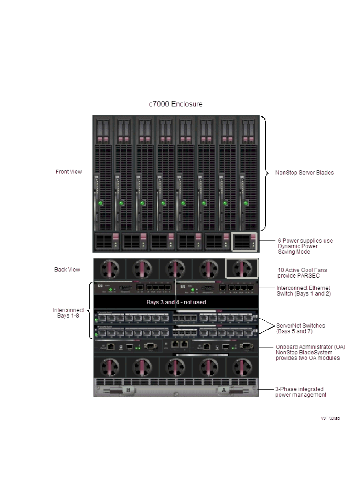
Figure 1-2 shows all of these c7000 features, except the HP Insight Display:
Figure 1-2 c7000 Enclosure Features
For information about the LEDs associated with the c7000 enclosure components, see the HP
BladeSystem c7000 Enclosure Setup and Installation Guide.
18 NonStop BladeSystem Overview
Page 19

NonStop Server Blade
The NonStop BL860c Server Blade is a two socket full-height server blade featuring an Intel®
Itanium® dual-core processor. Each server blade contains a ServerNet interface mezzanine card
with PCI-Express x4 to PCI-x bridge connections to provide ServerNet fabric connectivity. Other
features include four integrated Gigabit Ethernet ports for redundant network boot paths and
12 DIMM slots providing a maximum of 48 GB of memory per server blade.
IP CLuster I/O Module (CLIM)
The IP CLIM is a rack-mounted server that is part of some NonStop BladeSystem configurations.
The IP CLIM functions as a ServerNet Ethernet adapter providing HP standard Gigabit Ethernet
Network Interface Cards (NICs) to implement one of the IP CLIM configurations (either IP CLIM
A or IP CLIM B):
IP CLIM A Configuration (5 Copper Ports)
• Slot 1 contains a NIC that provides four copper Ethernet ports
• Eth01 port (between slots 1 and 2) provides one copper Ethernet port
• Slot 3 contains a ServerNet PCIe interface card, which provides the ServerNet fabric
connections
IP CLIM B Configuration (3 Copper/2 Fiber Ports)
• Slot 1 contains a NIC that provides three copper Ethernet ports
• Slots 2 contains a NIC that provides one fiber-optical Ethernet port
• Slot 3 contains a ServerNet interface PCIe card, which provides the ServerNet fabric
connections
• Slots 4 contains a NIC that provides one fiber-optical Ethernet port
For an illustration of the IP CLIM slots, see “Ethernet to Networks” (page 70).
NOTE: Both the IP and Storage CLIMs use the Cluster I/O Protocols (CIP) subsystem. For more
information about the CIP subsystem, see the Cluster I/O Protocols Configuration and Management
Manual.
Storage CLuster I/O Module (CLIM)
The Storage CLuster I/O Module (CLIM) is part of some NonStop BladeSystem configurations.
The Storage CLIM is a rack-mounted server and functions as a ServerNet I/O adapter providing:
• Dual ServerNet fabric connections
• A Serial Attached SCSI (SAS) interface for the storage subsystem via a SAS Host Bus Adapter
(HBA) supporting SAS disk drives and SAS tapes
• A Fibre Channel (FC) interface for ESS and FC tape devices via a customer-ordered FC HBA.
A Storage CLIM can have 0, 2, or 4 FC ports.
The Storage CLIM contains 5 PCIe HBA slots with these characteristics:
ProvidesConfigurationStorage CLIM HBA Slot
Part of base configuration5
Part of base configuration4
One SAS external and internal connector
with four SAS links per connector and 3
Gbps per link is provided by thePCIe 8x slot.
One SAS external connector with four SAS
links per connector and 3 Gbps per link is
provided by the PCIe 8x slot.
Part of base configuration3
ServerNet fabric connections via a PCIe 4x
adapter.
NonStop NB50000c BladeSystem 19
Page 20

ProvidesConfigurationStorage CLIM HBA Slot
SAS or Fibre ChannelOptional customer order2
SAS or Fibre ChannelOptional customer order1
Connections to FCDMs are not supported.
For an illustration of the Storage CLIM HBA slots, see “Storage CLIM Devices” (page 57).
SAS Disk Enclosure
The SAS disk enclosure is a rack-mounted disk enclosure and is part of some NonStop
BladeSystem configurations. The SAS disk enclosure supports up to 25 SAS disk drives, 3Gbps
SAS protocol, and a dual SAS domain from Storage CLIMs to dual port SAS disk drives. The
SAS disk enclosure supports connections to SAS disk drives. Connections to FCDMs are not
supported. For more information about the SAS disk enclosure, see the manual for your SAS
disk enclosure model (for example, the HP StorageWorks 70 Modular Smart Array Enclosure
Maintenance and Service Guide).
The SAS disk enclosure contains:
• 25, 2.5” disk drive slots with size options:
— 72GB, 15K rpm
— 146GB, 10K rpm
• Two independent I/O modules:
— SAS Domain A
— SAS Domain B
• Two fans
• Two power supplies
IOAM Enclosure
The IOAM enclosure is part of some NonStop BladeSystem configurations. The IOAM enclosure
uses Gigabit Ethernet 4-port ServerNet adapters (G4SAs) for networking connectivity and Fibre
Channel ServerNet adapters (FCSAs) for Fibre Channel connectivity between the system and
Fibre Channel disk modules (FCDMs), ESS, and Fibre Channel tape.
Fibre Channel Disk Module (FCDM)
The Fibre Channel disk module (FCDM) is a rack-mounted enclosure that can only be used with
NonStop BladeSystems that have IOAM enclosures. The FCDM connects to to an FCSA in an
IOAM enclosure and contains:
• Up to 14 Fibre Channel arbitrated loop disk drives (enclosure front)
• Environmental monitoring unit (EMU) (enclosure rear)
• Two fans and two power supplies
• Fibre Channel arbitrated loop (FC-AL) modules (enclosure rear)
You can daisy-chain together up to four FCDMs with 14 drives in each one.
Maintenance Switch
The HP ProCurve 2524 maintenance switch provides the communication between the NonStop
BladeSystem through the Onboard Administrator, c7000 enclosure interconnect Ethernet switch,
Storage and IP CLIMs, IOAM enclosures, the optional UPS, and the system console running HP
NonStop Open System Management (OSM). For a general description of the maintenance switch,
refer to the NonStop NS14000 Planning Guide. Details about the use or implementation of the
maintenance switch that are specific to a NonStop BladeSystem are presented here.
20 NonStop BladeSystem Overview
Page 21

The NonStopBladeSystem requires multiple connections tothe maintenance switch. The following
describes the required connections for each hardware component.
BladeSystem Connections to Maintenance Switch
• One connection per Onboard Administrator on the NonStop BladeSystem
• One connection per Interconnect Ethernet switch on the NonStop BladeSystem
• One connection to the optional UPS module
• One connection for the system console running OSM
CLIM Connections to Maintenance Switch
• One connection to the iLO port on a CLIM
• One connection to an eth0 port on a CLIM
IOAM Enclosure Connections to Maintenance Switch
• One connection to each of the two ServerNet switch boards in one I/O adapter module
(IOAM) enclosure.
• At least two connections to any two Gigabit Ethernet 4-port ServerNet adapters (G4SAs), if
the NonStop BladeSystem maintenance LAN is implemented through G4SAs.
System Console
A system console is a personal computer (PC) purchased from HP that runs maintenance and
diagnostic software for NonStop BladeSystems. When supplied with a new NonStop BladeSystem,
system consoles have factory-installed HP and third-party software for managing the system.
You can install software upgrades from the HP NonStop System Console Installer DVD image.
Some system console hardware, including the PC system unit, monitor, and keyboard, can be
mounted in the NonStop BladeSystem's 19-inch rack. Other PCs are installed outside the rack
and require separate provisions or furniture to hold the PC hardware.
For more information on the system console, refer to “System Consoles” (page 89).
UPS and ERM (Optional)
An uninterruptible power supply (UPS) is optional but recommended where a site UPS is not
available. HP supports the HP model R12000/3 UPS because it utilizes the power fail support
provided by the OSM. For information about the requirements for installing a UPS, see
“Uninterruptible Power Supply (UPS)” (page 32).
There are two different versions of the R12000/3 UPS:
• For North America and Japan, the HP AF429A is utilized and uses an IEC309 560P9 (60A)
input connector with 208V three phase (120V phase-to-neutral)
• For International, the HP AF430A is utilized and uses an IEC309 532P6 (32A) input connector
with 400V three phase (230V phase-to-neutral).
Cabinet configurations that include the HP UPS can also include extended runtime modules
(ERMs). An ERMis abattery module that extends the overallbattery-supported system run time.
NonStop NB50000c BladeSystem 21
Page 22

Up to four ERMs can be used for even longer battery-supported system run time. HP supports
the HP AF434A ERM.
WARNING! UPS's and ERMs must be mounted in the lowest portion of the NonStop
BladeSystem to avoid tipping and stability issues.
NOTE: The R12000/3 UPS has two output connectors. For I/O racks, only the output connector
to the rack level PDU is used. For processor racks, one output connector goes to the c7000 chassis
and the other to the rack PDU. For power feed setup instructions, see “NonStop BladeSystem
Power Distribution” (page 37) and “Power Feed Setup for the NonStop BladeSystem” (page 38).
For the R12000/3 UPS power and environmental requirements, refer to Chapter 3 (page 37). For
planning, installation, and emergency power-off (EPO) instructions, refer to the HP 3 Phase UPS
User Guide. This guide is available at:
http://bizsupport.austin.hp.com/bc/docs/support/SupportManual/c01079392/c01079392.pdf
For other UPS's, refer to the documentation shipped with the UPS.
Enterprise Storage System (Optional)
An Enterprise Storage System (ESS) is a collection of magnetic disks, their controllers, and a disk
cache in one or more standalone cabinets. ESS connects to the NonStop BladeSystem via the
Storage CLIM's Fibre Channel HBA ports (direct connect), Fibre Channel ports on the IOAM
enclosures (direct connect), or through a separate storage area network (SAN) using a Fibre
Channel SAN switch (switched connect). For more information about these connection types,
see your service provider.
NOTE: The Fibre Channel SAN switch power cords might not be compatible with the modular
cabinet PDU. Contact your service provider to order replacement power cords for the SAN switch
that are compatible with the modular cabinet PDU.
Cables and switches vary, depending on whether the connection is direct, switched, or a
combination:
Fibre Channel SwitchesCablesConnection
Direct connect
(LC-LC)
Storage CLIM (LC-MMF)
Storage CLIM (LC-MMF)
Combination of direct and switched
connection
switched connection
1 Customer must order the FC HBA ports on the Storage CLIM.
1
02 Fibre Channel ports on IOAM
02 Fibre Channel HBA ports on
1 or more4 Fibre Channel ports (LC-LC)Switched
1 or more4 Fibre Channel HBA ports on
12 Fibre Channel ports for each direct
14 Fibre Channel ports for each
Figure 1-3 shows an example of connections between two Storage CLIMs and an ESS via separate
Fibre Channel switches:
22 NonStop BladeSystem Overview
Page 23
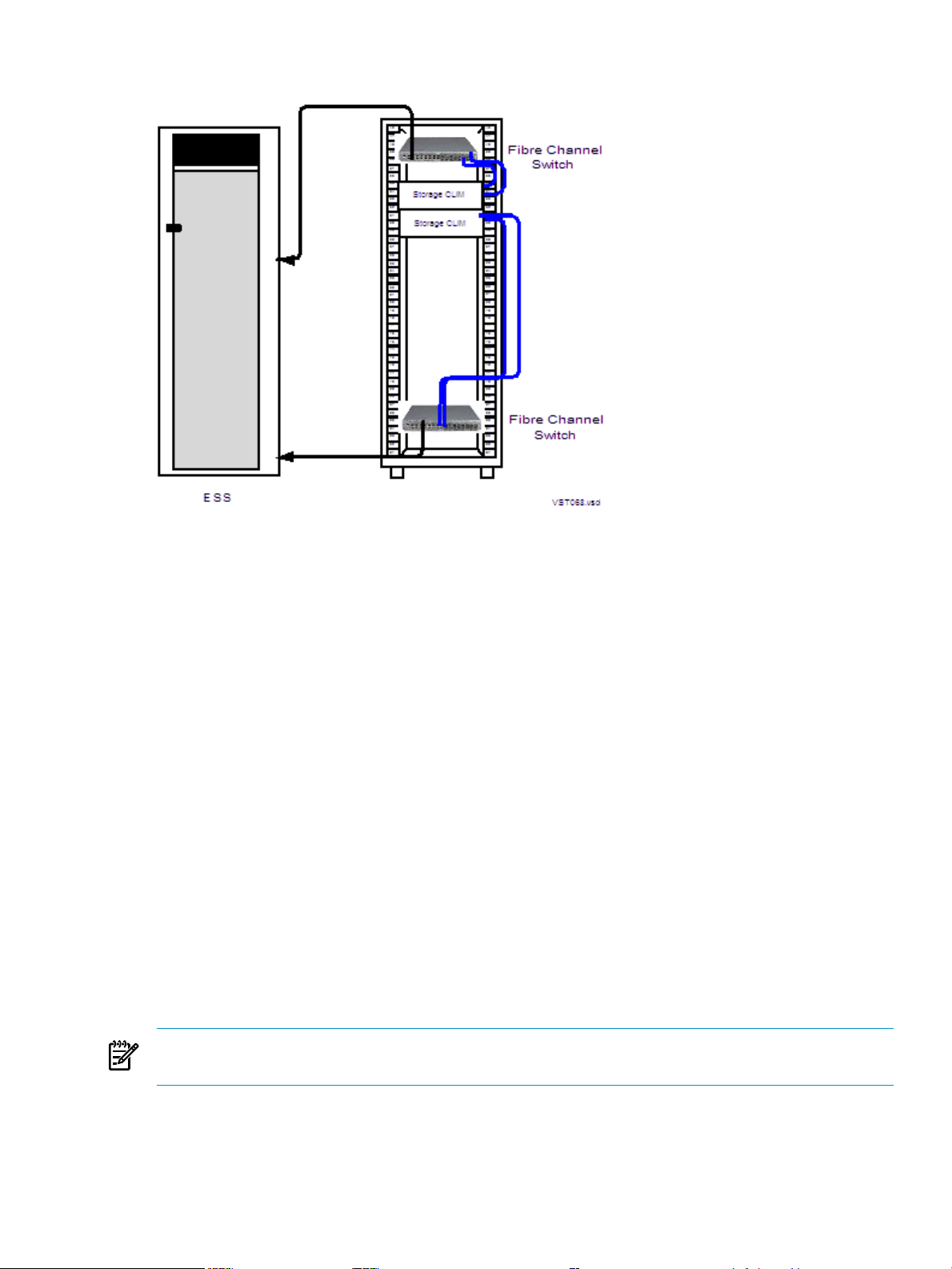
Figure 1-3 Connections Between Storage CLIMs and ESS
For fault tolerance, the primary and backup paths to an ESS logical device (LDEV) must go
through different Fibre Channel switches.
Some storage area procedures, such as reconfiguration, can cause the affected switches to pause.
If the pause is long enough, I/O failure occurs on all paths connected to that switch. If both the
primary and the backup paths are connected to the same switch, the LDEV goes down.
Refer to the documentation that accompanies the ESS.
Tape Drive and Interface Hardware (Optional)
For an overview of tape drives and the interface hardware, see “Fibre Channel Ports to Fibre
Tape Devices” (page 57) or “SAS Ports to SAS Tape Devices” (page 57).
For a list of supported tape devices, ask your service provider to refer to the NonStop BladeSystem
Hardware Installation Manual.
Preparation for Other Server Hardware
This guide provides the specifications only for the NonStop BladeSystem modular cabinets and
enclosures identified earlier in this section. For site preparation specifications for other HP
hardware that will be installed with the NonStop BladeSystems, consult your HP account team.
For site preparation specifications relating to hardware from other manufacturers, refer to the
documentation for those devices.
Management Tools for NonStop BladeSystems
NOTE: For information about changing the default passwords for NonStop BladeSystem
components and associated software, see “Changing Customer Passwords” (page 71).
This subsection describes the management tools available on your NonStop BladeSystem:
• “OSM Package” (page 24)
• “Onboard Administrator (OA)” (page 24)
• “Integrated Lights Out (iLO)” (page 24)
Preparation for Other Server Hardware 23
Page 24

• “Cluster I/O Protocols (CIP) Subsystem” (page 24)
• “Subsystem Control Facility (SCF) Subsystem” (page 24)
OSM Package
The HP Open System Management (OSM) product is the required system management tool for
NonStop BladeSystems. OSM works together with the Onboard Administrator (OA) and
Integrated Lights Out (iLO) management interfaces to manage c7000 enclosures. A new
client-based component, the OSM Certificate Tool, facilitates communication between OSM and
the OA.
For more information on the OSM package, including a description of the individual applications
see the OSM Migration and Configuration Guide and the OSM Service Connection User's Guide.
Onboard Administrator (OA)
The Onboard Administrator (OA) is the enclosure's management, processor, subsystem, and
firmware base and supports the c7000 enclosure and NonStop Server Blades. The OA software
is integrated with OSM and the Integrated Lights Out (iLO) management interface.
Integrated Lights Out (iLO)
iLO allows you to perform activities on the NonStop Bladesystem from a remote location and
provides anytime access to system management information such as hardware health, event logs
and configuration is available to troubleshoot and maintain the NonStop Server Blades.
Cluster I/O Protocols (CIP) Subsystem
The Cluster I/O Protocols (CIP) subsystem provides a configuration and management interface
for I/O on NonStop BladeSystems. The CIP subsystem has several tools for monitoring and
managing the subsystem. For more information about these tools and the CIP subsystem, see
the Cluster I/O Protocols (CIP) Configuration and Management Manual.
Subsystem Control Facility (SCF) Subsystem
The Subsystem Control Facility (SCF) also provides monitoring and management of the CIP
subsystem on the NonStop BladeSystem. See the Cluster I/O Protocols (CIP) Configuration and
Management Manual for more information about two subsystems with NonStop BladeSystems.
Component Location and Identification
This subsection includes these topics:
• “Terminology” (page 25)
• “Rack and Offset Physical Location” (page 26)
• “ServerNet Switch Group-Module-Slot Numbering” (page 26)
• “NonStop Server Blade Group-Module-Slot Numbering” (page 27)
• “CLIM Enclosure Group-Module-Slot-Port-Fiber Numbering” (page 27)
• “IOAM Enclosure Group-Module-Slot Numbering” (page 27)
• “Fibre Channel Disk Module Group-Module-Slot Numbering” (page 29)
24 NonStop BladeSystem Overview
Page 25

Terminology
These are terms used in locating and describing components:
DefinitionTerm
Cabinet
Rack
Rack Offset
Group
Module
Slot (or Bay or Position)
Port
Computer system housing that includes a structure of
external panels, front and rear doors, internal racking,
and dual PDUs.
Structure integrated into the cabinet into which
rackmountable components are assembled.
The rack uses this naming convention:
system-name-racknumber
The physical location of components installed in a
modular cabinet, measured in U values numbered 1 to
42, withU1 atthe bottomof thecabinet. AU is1.75 inches
(44 millimeters).
A subset of a system that contains one or more modules.
A group does not necessarily correspond to a single
physical object, such as an enclosure.
A subset of a group that is usually contained in an
enclosure. Amodule contains one or more slots (or bays).
A module can consist of components sharing a common
interconnect, such as a backplane, or it can be a logical
grouping ofcomponents performing a particular function.
A subset of a module that isthe logical or physical location
of a component within that module.
A connector to which a cable can be attached and which
transmits and receives data.
Fiber
• Group-Module-Slot (GMS)
• Group-Module-Slot-Bay (GMSB)
• Group-Module-Slot-Port (GMSP)
• Group-Module-Slot-Port-Fiber (GMSPF)
NonStop Server Blade
Number (one to four) of the fiber pair (LC connector)
within an MTP-LC fiber cable. An MTP-LC fiber cable
has a single MTP connector on one end and four LC
connectors, each containing a pair of fibers, at the other
end. The MTP connector connects to the ServerNet switch
in the c7000 enclosure and the LC connectors connect to
the CLIM
A notation method used by hardware and software in
NonStop systems for organizing and identifying the
location of certain hardware components.
A server blade that provides processing and ServerNet
connections.
On NonStop BladeSystems, locations of the modular components are identified by:
• Physical location:
— Rack number
— Rack offset
• Logical location: group, module, and slot (GMS) notation as defined by their position on
the ServerNet rather than the physical location
OSM uses GMS notation in many places, including the Tree view and Attributes window, and
it uses rack and offset information to create displays of the server and its components.
Component Location and Identification 25
Page 26
Rack and Offset Physical Location
Rack nameand rack offset identify the physical location of components in a NonStop BladeSystem.
The rack name is located on an external label affixed to the rack, which includes the system name
plus a 2-digit rack number.
Rack offset is labeled on the rails in each side of the rack. These rails are measured vertically in
units called U, with one U measuring 1.75 inches (44 millimeters). The rack is 42U with U1 located
at the bottom and 42U at the top. The rack offset is the lowest number on the rack that the
component occupies.
ServerNet Switch Group-Module-Slot Numbering
• Group (100-101):
— Group 100 is the first c7000 processor enclosure containing logical processors 0-7.
— Group 101 is the second c7000 processor enclosure containing logical processors 8-15.
• Module (2-3):
— Module 2 is the X fabric.
— Module 3 is the Y fabric.
• Slot (5 or 7):
— Slot 5 contains the double-wide ServerNet switch for the X fabric.
— Slot 7 contains the double-wide ServerNet switch for the Y fabric.
NOTE: There are two types of c7000 ServerNet switches: Standard I/O and High I/O. For
more information and illustrations of the ServerNet switch ports, refer to “I/O Connections
(Standard and High I/O ServerNet Switch Configurations)” (page 55).
• Port (1-18):
— Ports 1 through 2 support the inter-enclosure links. Port 1 is marked GA. Port 2 is
marked GB.
— Ports 3 through 8 support the I/O links (IP CLIM, Storage CLIM, and IOAM)
NOTE: IOAMs must use Ports 4 through 7. These ports support 4-way IOAM links.
— Ports 9 and 10 support the cross links between two ServerNet switches in the same
enclosure.
— Ports 11 and 12 support the links to a cluster switch. SH on Port 11 stands for short haul.
LH on Port 12 stands for long haul.
— Ports 13 through 18 are not supported.
• Fiber (1-4)
These fibers support up to 4 ServerNet links on ports 3-8 of the c7000 enclosure ServerNet
switch.
26 NonStop BladeSystem Overview
Page 27

NonStop Server Blade Group-Module-Slot Numbering
These tablesshow the default numberingfor the NonStop Server Blades of a NonStop BladeSystem
when the server blades are powered on and functioning:
GMS Numbering For the Logical Processors:
Slot*ModuleGroup*Processor ID
111000
211001
311002
411003
511004
611005
711006
811007
111018
211019
*In the OSM Service Connection, the term Enclosure is used for the group and the term Bay is used for the slot.
CLIM Enclosure Group-Module-Slot-Port-Fiber Numbering
This table shows the valid values for GMSPF numbering for the X1 ServerNet switch connection
point to a CLIM:
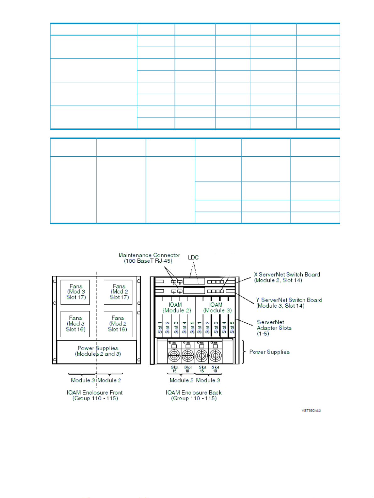
IOAM Enclosure Group-Module-Slot Numbering
A NonStop BladeSystem supports IOAM enclosures, identified as group 110 through 115:
3110110
4110111
5110112
6110113
7110114
8110115
FibersPortsSlotsModuleGroup
1 - 43 to 85, 72, 3100-101ServerNet switch
FiberPortSlotModuleGroupIOAM
1 - 44 (EA)52100110
1 - 44 (EA)73100
1 - 46 (EC)52100111
1 - 46 (EC)73100
Component Location and Identification 27
Page 28
FiberPortSlotModuleGroupIOAM
1 - 45 (EB)52100112
1 - 45 (EB)73100
1 - 47 (ED)52100113
1 - 47 (ED)73100
1 - 44 (EA)52101114
1 - 44 (EA)73101
1 - 46 (EC)52101115
1 - 46 (EC)73101
IOAM Group
preceding table.)
X ServerNet
Module
Module
1 to 532110 - 115 (See
14
ServerNet
adapters
logic board
This illustration shows the slot locations for the IOAM enclosure:
PortItemSlotY ServerNet
1 - n: where n is
number of ports
on adapter
1 - 4ServerNet switch
-Power supplies15, 18
-Fans16, 17
28 NonStop BladeSystem Overview
Page 29
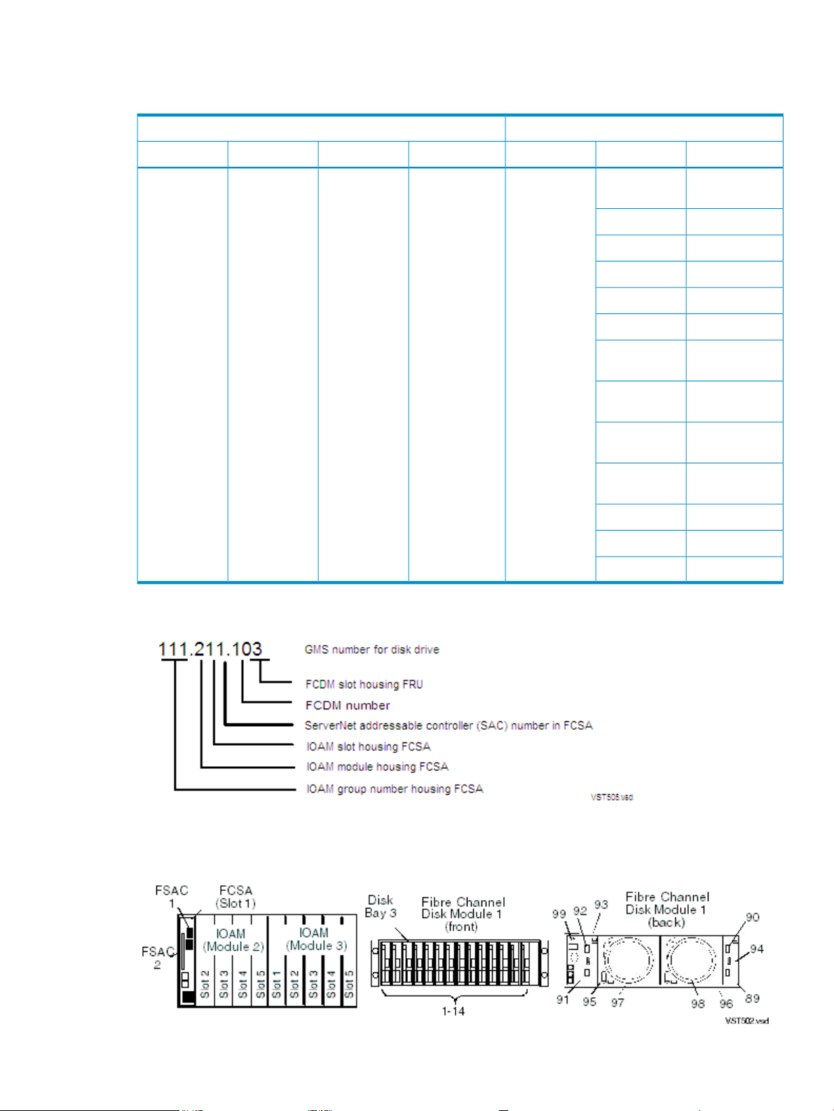
Fibre Channel Disk Module Group-Module-Slot Numbering
This table shows the default numbering for the Fibre Channel disk module:
FCDMIOAM Enclosure
ItemSlotShelfFCSA F-SACsSlotModuleGroup
110-115
3 - Y fabric
1, 21 - 52 - X fabric;
daisy-chained;
1 if single disk
enclosure
01 - 4 if
93
94
95
96
Fibre Channel
disk module
Disk drive bays1-14
Transceiver A189
Transceiver A290
Transceiver B191
Transceiver B292
Left FC-AL
board
Right FC-AL
board
Left power
supply
Right power
supply
Left blower97
Right blower98
EMU99
The form of the GMS numbering for a disk in a Fibre Channel disk module is:
This example shows the disk in bay 03 of the Fibre Channel disk module that connects to the
FCSA in the IOAM group 111, module 2, slot 1, FSAC 1:
Component Location and Identification 29
Page 30

System Installation Document Packet
To keep track of the hardware configuration, internal and external communications cabling, IP
addresses, and connect networks, assemble and retain as the systems records an Installation
Document Packet. This packet can include:
• “Technical Document for the Factory-Installed Hardware Configuration”
• “Configuration Forms for the ServerNet Adapters and CLIMs”
Technical Document for the Factory-Installed Hardware Configuration
Each new NonStop BladeSystem includes a document that describes:
• The cabinet included with the system
• Each hardware enclosure installed in the cabinet
• Cabinet U location of the bottom edge of each enclosure
• Each ServerNet cable with:
— Source and destination enclosure, component, and connector
— Cable part number
— Source and destination connection labels
This document is called a technical document and serves as the physical location and connection
map for the system.
Configuration Forms for the ServerNet Adapters and CLIMs
To add configuration forms for ServerNet adapters or CLIMs to your Installation Document
Packet, copy the necessary forms from the adapter manuals or the CLuster I/O Module (CLIM)
Installation and Configuration Guide. Follow any planning instructions in these manuals.
30 NonStop BladeSystem Overview
Page 31

2 Site Preparation Guidelines
This section describes power, environmental, and space considerations for your site.
Modular Cabinet Power and I/O Cable Entry
Power and I/O cables can enter the NonStop BladeSystem from either the top or the bottom rear
of the modular cabinets, depending on how the cabinets are ordered from HP and the routing
of the AC power feeds at the site. NonStop BladeSystem cabinets can be ordered with the AC
power cords for the PDUs exiting either:
• Top: Power and I/O cables are routed from above the modular cabinet.
• Bottom: Power and I/O cables are routed from below the modular cabinet
For information about modular cabinet power and cable options, refer to “AC Input Power for
Modular Cabinets” (page 44).
Emergency Power-Off Switches
Emergency power off (EPO) switches are required by local codes or other applicable regulations
when computer equipment contains batteries capable of supplying more than 750 volt-amperes
(VA) for more that five minutes. Systems that have thesebatteries also have internal EPO hardware
for connection to a site EPO switch or relay. In an emergency, activating the EPO switch or relay
removes power from all electrical equipment in the computer room (except that used for lighting
and fire-related sensors and alarms).
EPO Requirement for NonStop BladeSystems
NonStop BladeSystems without an optional UPS (such as an HP R12000/3 UPS) installed in the
modular cabinet do not contain batteries capable of supplying more than 750 volt-amperes (VA)
for more that five minutes, so they do not require connection to a site EPO switch.
EPO Requirement for HP R12000/3 UPS
The rack-mounted HP R12000/3, 12kVA UPS can be optionally installed in a modular cabinet,
contains batteries, and has a remote EPO (REPO) port. For site EPO switches or relays, consult
your HP site preparation specialist or electrical engineer regarding requirements.
If an EPO switch or relay connector is required for your site, contact your HP representative or
refer to the HP 3 Phase UPS User Guide for connector and wiring for the 12kVA model. This guide
is available at:
http://bizsupport.austin.hp.com/bc/docs/support/SupportManual/c01079392/c01079392.pdf
Electrical Power and Grounding Quality
Proper design and installation of a power distribution system for a NonStop BladeSystem requires
specialized skills,knowledge, and understanding of appropriate electrical codes and the limitations
of the power systems for computer and data processing equipment. For power and grounding
specifications, refer to “AC Input Power for Modular Cabinets” (page 44).
Power Quality
This equipment is designed to operate reliably over a wide range of voltages and frequencies,
described in “Enclosure AC Input” (page 45). However, damage can occur if these ranges are
Modular Cabinet Power and I/O Cable Entry 31
Page 32

exceeded. Severe electrical disturbances can exceed the design specifications of the equipment.
Common sources of such disturbances are:
• Fluctuations occurring within the facility’s distribution system
• Utility service low-voltage conditions (such as sags or brownouts)
• Wide and rapid variations in input voltage levels
• Wide and rapid variations in input power frequency
• Electrical storms
• Large inductive sources (such as motors and welders)
• Faults in the distribution system wiring (such as loose connections)
Computer systems can be protected from the sources of many of these electrical disturbances by
using:
• A dedicated power distribution system
• Power conditioning equipment
• Lightning arresters on power cables to protect equipment against electrical storms
For steps to take to ensure proper power for the servers, consult with your HP site preparation
specialist or power engineer.
Grounding Systems
The site building must provide a power distribution safety ground/protective earth for each AC
service entrance to all NonStop BladeSystem equipment. This safety grounding system must
comply with local codes and any other applicable regulations for the installation locale.
For proper grounding/protective earth connection, consult with your HP site preparation specialist
or power engineer.
Power Consumption
In a NonStop BladeSystem, the power consumption and inrush currents per connection can vary
because of the unique combination of enclosures housed in the modular cabinet. Thus, the total
power consumption for the hardware installed in the cabinet should be calculated as described
in “Enclosure Power Loads” (page 46).
Uninterruptible Power Supply (UPS)
Modular cabinets do not have built-in batteries to provide power during power failures. To
support system operation and ride-through support during a power failure, NonStop
BladeSystems require either an optional UPS (HP supports the HP model R12000/3 UPS) installed
in each modular cabinet or a site UPS to support system operation through a power failure. This
system operation support can include a planned orderly shutdown at a predetermined time in
the event of an extended power failure. A timely and orderly shutdown prevents an uncontrolled
and asymmetric shutdown of the system resources from depleted UPS batteries.
OSM provides this ride-through support during a power failure. When OSM detects a power
failure, it triggers a ride-through timer. To set this timer, you must configure the ride-through
time in SCF. For this information, refer to the SCF Reference Manual for the Kernel Subsystem. If
AC power is not restored before the configured ride-through time period ends, OSM initiates
an orderly shutdown of I/O operations and processors. For additional information, see “AC
Power Monitoring” (page 95).
32 Site Preparation Guidelines
Page 33

NOTE: Retrofitting a system in the field with a UPS and ERMs will likely require moving all
installed enclosures in the rack to provide space for the new hardware. One or more of the
enclosures that formerly resided in the rackmight be displaced and therefore have to be installed
in another rack that would also need a UPS and ERMs installed. Additionally, lifting equipment
might be required to lift heavy enclosures to their new location.
For information and specifications on the R12000/3 UPS, see Chapter 3 (page 37) and refer to
the HP 3 Phase UPS User Guide. This guide is available at:
http://bizsupport.austin.hp.com/bc/docs/support/SupportManual/c01079392/c01079392.pdf
If you install a UPS other than the HP model R12000/3 UPS in each modular cabinet of a NonStop
BladeSystem, these requirements must be met to insure the system can survive a total AC power
fail:
• The UPS output voltage can support the HP PDU input voltage requirements.
• The UPS phase output matches the PDU phase input. For NonStop BladeSystems, 3-phase
output UPSs and 3-phase input HP PDUs are supported. For details, refer to Chapter 3
(page 37).
• The UPS output can support the targeted system in the event of an AC power failure.
Calculate each cabinet load to insure the UPS can support a proper ride-through time in the
event of a total AC power failure. For more information, refer to “Enclosure Power Loads”
(page 46).
NOTE: A UPS other than the HP model R12000/3 UPS will not be able to utilize the power
fail support of the Configure a Power Source as UPS OSM action.
If your applications require a UPS that supports the entire system or even a UPS or motor
generator for all computer and support equipment in the site, you must plan the site’s electrical
infrastructure accordingly.
Cooling and Humidity Control
Do not rely on an intuitive approach to design cooling or to simply achieve an energy
balance—that is, summing up to the total power dissipation from all the hardware and sizing a
comparable air conditioning capacity. Today’s high-performance NonStop BladeSystems use
semiconductors that integrate multiple functions on a single chip with very high power densities.
These chips, plus high-power-density mass storage and power supplies, are mounted in ultra-thin
system and storage enclosures, and then deployed into computer racks in large numbers. This
higher concentration of devices results in localized heat, which increases the potential for hot
spots that can damage the equipment.
Additionally, variables in the installation site layout can adversely affect air flows and create hot
spots by allowing hot and cool air streams to mix. Studies have shown that above 70°F (20°C),
every increase of 18°F (10°C) reduces long-term electronics reliability by 50%.
Cooling airflow through each enclosure in the NonStop BladeSystem is front-to-back. Because
of high heat densities and hot spots, an accurate assessment of air flow around and through the
system equipment and specialized cooling design is essential for reliable system operation. For
an airflow assessment, consult with your HP cooling consultant or your heating, ventilation, and
air conditioning (HVAC) engineer.
Cooling and Humidity Control 33
Page 34

NOTE: Failure of site cooling with the NonStop BladeSystem continuing to run can cause rapid
heat buildup and excessive temperatures within the hardware. Excessive internal temperatures
can result in full or partial system shutdown. Ensure that the site’s cooling system remains fully
operational when the NonStop BladeSystem is running.
Because each modular cabinet houses a unique combination of enclosures, use the “Heat
Dissipation Specifications and Worksheet” (page 50) to calculate the total heat dissipation for
the hardware installed in each cabinet. For air temperature levels at the site, refer to “Operating
Temperature, Humidity, and Altitude” (page 50).
Weight
Because modular cabinets for NonStop BladeSystems house a unique combination of enclosures,
total weight must be calculated based on what is in the specific cabinet, as described in “Modular
Cabinet and Enclosure Weights With Worksheet ” (page 49).
Flooring
NonStop BladeSystems can be installed either on the site’s floor with the cables entering from
above the equipment or on raised flooring with power and I/O cables entering from underneath.
Because cooling airflow through each enclosure in the modular cabinets is front-to-back, raised
flooring is not required for system cooling.
The site floor structure and any raised flooring (if used) must be able to support the total weight
of the installed computer system as well as the weight of the individual modular cabinets and
their enclosures as they are moved into position. To determine the total weight of each modular
cabinet with its installed enclosures, refer to “Modular Cabinet and Enclosure Weights With
Worksheet ” (page 49).
For your site’s floor system, consult with your HP site preparation specialist or an appropriate
floor system engineer. If raised flooring is to be used, the design of the NonStop BladeSystem
modular cabinet is optimized for placement on 24-inch floor panels.
Dust and Pollution Control
NonStop BladeSystemsdo not have air filters. Any computer equipmentcan be adversely affected
by dust and microscopic particles in the site environment. Airborne dust can blanket electronic
components on printed circuit boards, inhibiting cooling airflow and causing premature failure
from excess heat, humidity, or both. Metallically conductive particles can short circuit electronic
components. Tape drives and some other mechanical devices can experience failures resulting
from airborne abrasive particles.
For recommendations to keep the site as free of dust and pollution as possible, consult with your
heating, ventilation, and air conditioning (HVAC) engineer or your HP site preparation specialist.
Zinc Particulates
Over time, fine whiskers of pure metal can form on electroplated zinc, cadmium, or tin surfaces
such as aged raised flooring panels and supports. If these whiskers are disturbed, they can break
off and become airborne, possibly causing computer failures or operational interruptions. This
metallic particulate contamination is a relatively rare but possible threat. Kits are available to
test for metallic particulate contamination, or you can request that your site preparation specialist
or HVAC engineer test the site for contamination before installing any electronic equipment.
Space for Receiving and Unpacking the System
Identify areas that are large enough to receive and to unpack the system from its shipping cartons
and pallets. Be sure to allow adequate space to remove the system equipment from the shipping
34 Site Preparation Guidelines
Page 35

pallets using supplied ramps. Also be sure adequate personnel are present to remove each cabinet
from its shipping pallet and to safely move it to the installation site.
WARNING! A fully populated cabinet is unstable when moving down the unloading ramp
from its shipping pallet. Arrange for enough personnel to stabilize each cabinet during removal
from the pallet and to prevent the cabinet from falling. A falling cabinet can cause serious or
fatal personal injury.
Ensure sufficient pathways and clearances for moving the NonStop BladeSystem equipment
safely from the receiving and unpacking areas to the installation site. Verify that door and hallway
width and height as well as floor and elevator loading will accommodate not only the system
equipment but also all required personnel and lifting or moving devices. If necessary, enlarge
or remove any obstructing doorway or wall.
All modular cabinets have small casters to facilitate moving them on hard flooring from the
unpacking area to the site. Because of these small casters, rolling modular cabinets along carpeted
or tiled pathways might be difficult. If necessary, plan for a temporary hard floor covering in
affected pathways for easier movement of the equipment.
For physical dimensions of the NonStop BladeSystem equipment, refer to “Dimensions and
Weights” (page 47).
Operational Space
When planning the layout of the NonStop BladeSystem site, use the equipment dimensions, door
swing, and service clearances listed in “Dimensions and Weights” (page 47). Because location
of the lighting fixtures and electrical outlets affects servicing operations, consider an equipment
layout that takes advantage of existing lighting and electrical outlets.
Also consider the location and orientation of current or future air conditioning ducts and airflow
direction and eliminate any obstructions to equipment intake or exhaust air flow. Refer to “Cooling
and Humidity Control” (page 33).
Space planning should also include the possible addition of equipment or other changes in space
requirements. Depending on the current or future equipment installed at your site, layout plans
can also include provisions for:
• Channels or fixtures used for routing data cables and power cables
• Access to air conditioning ducts, filters, lighting, and electrical power hardware
• Communications cables, patch panels, and switch equipment
• Power conditioning equipment
• Storage area or cabinets for supplies, media, and spare parts
Operational Space 35
Page 36

36
Page 37

3 System Installation Specifications
This section provides specifications necessary for system installation planning.
NOTE: All specifications provided in this section assume that each enclosure in the modular
cabinet is fully populated. The maximum current for each AC service depends on the number
and type of enclosures installed in the modular cabinet. Power, weight, and heat loads are less
when enclosures are not fully populated; for example, a Fibre Channel disk module with fewer
disks.
Modular Cabinets
The modular cabinet is a EIA standard 19-inch, 42U rack for mounting modular components.
The modular cabinet comes equipped with front and rear doors and includes a rear extension
that makes it deeper than some industry-standard racks. The “Power Distribution Units (PDUs)”
(page 42) are mounted along the rear extension without occupying any U-space in the cabinet
and are oriented inward, facing the components within the rack.
NonStop BladeSystem Power Distribution
There are two power configurations for NonStop BladeSystems:
• North America/Japan (NA/JPN): requires 208V three phase (120V phase to neutral) and
loads wired phase-to-phase
• International (INTL): requires 400V three phase with loads wired phase to neutral (230V)
Both power configurations require 200V to 240V distribution and careful attention to phase load
balancing. For more information, see “Phase Load Balancing” (page 45).
The NonStop BladeSystem's three-phase, c7000 enclosure contains an AC Input Module that
provides 2N redundant power distribution for the power configurations. This power module
comes with a pair of power cords that provide direct AC power feeds to the c7000 enclosure:
Modular Cabinets 37
Page 38

One c7000 power feed is from the main power source and the other is from a backup UPS grid.
For the R12000/3 UPS installed in a rack, the backup power source for the c7000 is one of the
dedicated three phase outputs. There is no power sharing between the c7000 and the rack PDU
feed. Two three-phase rack PDUspower all the other componentsexcept the c7000 in the NonStop
BladeSystem. One PDU is connected to the main power input grid: the other to the backup grid.
For racks with integral UPS, this is one of the dedicated three phase outputs of the UPS. For
c7000 power setup details, see “Power Feed Setup for the NonStop BladeSystem” (page 38)
There are two different versions of the rack level PDU. For more details, see “Power Distribution
Units (PDUs)” (page 42) and “AC Input Power for Modular Cabinets” (page 44).
Power Feed Setup for the NonStop BladeSystem
Power set up depends on your power configuration type:
• “North America/Japan Power Setup With Rack-Mounted UPS”
• “North America/Japan Power Setup Without Rack-Mounted UPS” (page 39)
• “International Power Setup With Rack-Mounted UPS” (page 40)
• “International Power Setup Without Rack-Mounted UPS” (page 41)
North America/Japan Power Setup With Rack-Mounted UPS
To setup the power feed connections as shown in Figure 3-1:
1. Connect one 3-phase 60A power feed to the rack-mounted UPS IEC309 560P9 (60A, 5 wire/4
pole) input connector.
2. Connect one 3-phase 30A power feed to the AF504A PDU NEMA L15-30P (30A, 4 wire/3
pole) input connector.
3. Connect one 3-phase 30A power feed to the c7000 enclosure's NEMA L15-30P (30A, 4 wire/3
pole) input connector.
38 System Installation Specifications
Page 39

Figure 3-1 North America/Japan 3-Phase Power Setup With Rack-Mounted UPS
North America/Japan Power Setup Without Rack-Mounted UPS
To setup the power feed connections as shown in Figure 3-2:
1. Connect two 3-phase 30A power feeds to the two AF504A PDU NEMA L15-30P (30A, 4
wire/3 pole) input connectors.
2. Connect two 3-phase 30A power feeds to the two NEMA L15-30P (30A, 4 wire/3 pole) input
connectors within the c7000 enclosure.
NonStop BladeSystem Power Distribution 39
Page 40

Figure 3-2 North America/Japan Power Setup
International Power Setup With Rack-Mounted UPS
To setup the power feed connections as shown in Figure 3-3 (page 41):
1. Connect one 3-phase 32A power feed to the rack-mounted UPS IEC309 532P6 (32A, 5 wire/4
pole) input connector.
2. Connect one 3-phase 16A power feed to the AF508A PDU IEC309 516P6 (16A, 5 wire/4 pole)
input connector.
3. Connect one 3-phase 16A power feed to the c7000 enclosure's IEC309 516P6 (16A, 5 wire/4
pole) input connector.
40 System Installation Specifications
Page 41

Figure 3-3 International 3-Phase Power Setup With UPS
International Power Setup Without Rack-Mounted UPS
To setup the power feed connections as shown in Figure 3-4:
1. Connect two 3-phase 16A power feeds to the two AF508A PDU IEC309 516P6 (16A, 5 wire/4
pole) input connectors.
2. Connect two 3-phase 16A power feeds to the two IEC309 516P6 (16A, 5 wire/4 pole) input
connectors within the c7000 enclosure.
NonStop BladeSystem Power Distribution 41
Page 42

Figure 3-4 International Power Setup Without Rack-Mounted UPS
Power Distribution Units (PDUs)
Two power distribution units (PDUs) are installed to provide redundant power outlets for the
components mounted in the modular cabinet. The PDUs are oriented inward, facing the
components within the rack. Each PDU is 60 inches long and has 39 AC receptacles, three circuit
breakers, and an AC power cord. The PDU is oriented with the AC power cord exiting the
modular cabinet at either the top or bottom rear corners of the cabinet, depending on the site's
power feed needs.
For information about specific PDU input and output characteristics for PDUs factory-installed
in modular cabinets, refer to “AC Input Power for Modular Cabinets” (page 44).
Each PDU in a modular cabinet has:
• 36 AC receptacles per PDU (12 per segment) - IEC 320 C13 10A receptacle type
• 3 AC receptacles per PDU (1 per segment) - IEC 320 C19 16A receptacle type
• 3 circuit-breakers
These PDU options are available to receive power from the site AC power source:
• 208 V AC, three-phase delta for North America and Japan
• 400 V AC, three-phase wye for International
Each PDU distributes site three-phase power to 39 single-phase 200 to 240 V AC outlets for
connecting the power cords from the components mounted in the modular cabinet.
The AC power feed cables for the PDUs are mounted to exit the modular cabinet at either the
top or bottom rear corners of the cabinet depending on what is ordered for the site's power feed.
42 System Installation Specifications
Page 43

Figure 3-5 shows the power feed cables on PDUs with AC feed at the bottom of the cabinet and
the AC power outlets along the PDU. These power outlets face in toward the components in the
cabinet.
Figure 3-5 Bottom AC Power Feed
Figure 3-6 shows the power feed cables on PDUs with AC feed at the top of the cabinet:
Figure 3-6 Top AC Power Feed
Power Distribution Units (PDUs) 43
Page 44

AC Input Power for Modular Cabinets
This subsection provides information about AC input power for modular cabinets and covers
these topics:
• “North America and Japan: 208 V AC PDU Power”
• “International: 400 V AC PDU Power”
• “Branch Circuits and Circuit Breakers”
• “Enclosure AC Input” (page 45)
• “Enclosure Power Loads” (page 46)
Power can enter the NonStop BladeSystem from either the top or the bottom rear of the modular
cabinets, depending on how the cabinets are ordered from HP and the AC power feeds are routed
at the site. NonStop BladeSystem cabinets can be ordered with the AC power cords for the PDU
installed either:
• Top: Power and I/O cables are routed from above the modular cabinet.
• Bottom: Power and I/O cables are routed from below the modular cabinet
For information on the modular cabinets, refer to “Modular Cabinets” (page 37). For information
on the PDUs, refer to “Power Distribution Units (PDUs)” (page 42).
North America and Japan: 208 V AC PDU Power
The cabinet includes two power distribution units (PDU). The PDU power characteristics are:
PDU input characteristics
PDU output characteristics
International: 400 V AC PDU Power
The cabinet includes two power distribution units (PDU). The PDU power characteristics are:
PDU input characteristics
PDU output characteristics
• 208 V AC, 3-phase delta, 24A RMS, 4-wire
• 50/60Hz
• NEMA L15-30 input plug
• 6.5 feet (2 m) attached power cord
• 3 circuit-breaker-protected 13.86A load segments
• 36 AC receptacles per PDU (12 per segment) - IEC 320
C13 10A receptacle type
• 3 AC receptacles per PDU (1 per segment) - IEC 320
C19 16A receptacle type
• 380 to 415 V AC, 3-phase Wye, 16A RMS, 5-wire
• 50/60Hz
• IEC309 5-pin, 16A input plug
• 6.5 feet (2 m) attached harmonized power cord
• 3 circuit-breaker-protected 16A load segments
• 36 AC receptacles per PDU (12 per segment) - IEC 320
C13 10A receptacle type
• 3 AC receptacles per PDU (1 per segment) - IEC 320
C19 16A receptacle type
Branch Circuits and Circuit Breakers
Modular cabinets for the NonStop BladeSystem contain two PDUs.
44 System Installation Specifications
Page 45

In cabinets without the optional rack-mounted UPS, each of the two PDUs requires a separate
branch circuit of these ratings:
Amps (see following “CAUTION”)VoltsRegion
30208North America and Japan
1
400International
1 Category D circuit breaker is required.
16
CAUTION: Be sure the hardware configuration and resultant power loads of each cabinet within
the system do not exceed the capacity of the branch circuit according to applicable electrical
codes and regulations.
Branch circuit requirements vary by the input voltage and the local codes and applicable
regulations regarding maximum circuit and total distribution loading.
Select circuit breaker ratings according to local codes and any applicable regulations for the
circuit capacity. Note that circuit breaker ratings vary if your system includes the optional
rack-mounted HP Model R12000/3 Integrated UPS.
These ratings apply to systems with the optional rack-mounted HP Model R12000/3 Integrated
UPS:
Version
Japan
1 The UPS input requires a dedicated (unshared) branch circuit that is suitably rated for your specific UPS.
For further information and specifications on the R12000/3 UPS (12kVA model), refer to the HP
3 Phase UPS User Guide for the 12kVA model. This guide is available at:
http://bizsupport.austin.hp.com/bc/docs/support/SupportManual/c01079392/c01079392.pdf
Enclosure AC Input
Enclosures (c7000, IP CLIM, IOAM enclosure, and so forth) require:
Settings
Input PlugPower Out (VA/Watts)Operating Voltage
ValueSpecification
200/208/220/230/240 V AC RMSNominal input voltage
180-264 V ACVoltage range*
50 or 60 HzNominal line frequency
47-53 Hz or 57-63 HzFrequency ranges
UPS Input Rating
Dedicated 36 AmpIEC-309 60 Amp12000208North America and
Dedicated 24 AmpIEC-309 32 Amp12000230International
1
Phase Load Balancing
Each PDU is wired such that there are three load segments with groups of outlets alternating
between load segments, going up and down the PDU. Refer to “Power Distribution Units (PDUs)”
(page 42). Factory-installed enclosures, other than the c7000, are connected to the PDUs on
alternating load segments to facilitate phase load balancing. The c7000 has its own three-phase
3Number of phases (c7000 enclosure only)
1Number of phases (all other components)
AC Input Power for Modular Cabinets 45
Page 46

input, with each phase (International) or pairs of phases (North America/Japan) associated with
one of the c7000 power supplies. When the c7000 is operating in Dynamic Power Saving Mode,
the minimum number of power supplies are enabled to redundantly power the enclosure. This
mode increases power supply efficiency, but leaves the phases or phase pairs associated with
the disabled power supplies unloaded. For multiple-cabinet installations, in order to balance
phase loads when Dynamic Power Saving Mode is enabled, HP recommends rotating the phases
from one cabinet to the next. For example, if the first cabinet is wired A-B-C, the next cabinet
should be wired B-C-A, and the next C-A-B, and so on.
Enclosure Power Loads
The total power and current load for a modular cabinet depends on the number and type of
enclosures installed in it. Therefore, the total load is the sum of the loads for all enclosures
installed. For examples of calculating the power and current load for various enclosure
combinations, refer to “Calculating Specifications for Enclosure Combinations” (page 51).
In normal operation, the AC power is split equally between the two PDUs in the modular cabinet.
However, if one of the two AC power feeds fails, the remaining AC power feed and PDU must
carry the power for all enclosures in that cabinet.
Power and current specifications for each type of enclosure are:
Enclosure Type
3
c7000
SAS disk
enclosure
disk module
system console
keyboard and
monitor
switch
(Ethernet)
4
5
AC Power Lines
per Enclosure
Apparent Power
1
(volt-amps
measured on
single AC line with
one line powered)
Apparent Power (volt-amps measured
on single AC line with both lines
powered)
2
Total:Per line:
Peak Inrush
Current (amps)
2104400220043002
153701853202IP CLIM
153701853202Storage CLIM
52801402602
303261632622IOAM enclosure
143481742902Fibre Channel
27--1761Rack-mounted
2--281Rack-mounted
4--441Maintenance
1 See “Power Feed Setup for the NonStop BladeSystem” (page 38) for c7000 enclosure power feed requirements.
2 Total apparent power is the sum of the two AC power lines feeding the enclosure. Electrical load is shared equally
between the two lines.
3 Decrease the apparent power VA specification by 508VA for each empty Nonstop server blade slot. For example, a
c7000 that only has four NonStop Server Blades installed would be rated 4400 VA minus (4 server blades x 508 VA)
= 2370 VA apparent power.
4 Measured with 14 disk drives installed and active.
5 Maintenance switch has only one AC plug.
46 System Installation Specifications
Page 47

Dimensions and Weights
This subsection provides information about the dimensions and weights for modular cabinets
and enclosures installed in a modular cabinet and covers these topics:
• “Plan View of the 42U Modular Cabinet”
• “Service Clearances for the Modular Cabinets”
• “Unit Sizes”
• “42U Modular Cabinet Physical Specifications” (page 48)
• “Enclosure Dimensions” (page 48)
• “Modular Cabinet and Enclosure Weights With Worksheet ” (page 49)
Plan View of the 42U Modular Cabinet
Service Clearances for the Modular Cabinets
Aisles: 6 feet (182.9 centimeters)
Front: 3 feet (91.4 centimeters)
Rear: 3 feet (91.4 centimeters)
Unit Sizes
Height (U)Enclosure Type
42Modular cabinet
10c7000 enclosure
2IP CLIM
2Storage CLIM
2SAS disk enclosure
11IOAM enclosure
3Fibre Channel disk module (FCDM)
Dimensions and Weights 47
Page 48

42U Modular Cabinet Physical Specifications
Height (U)Enclosure Type
1Maintenance switch (Ethernet)
6R12000/3 UPS
3Extended runtime module
2Rack-mounted system console
WeightDepthWidthHeightItem
cmin.cmin.cmin.
cabinet
door
door
(palletized)
Enclosure Dimensions
enclosure
CLIM
118.646.760.9624.0199.978.7Modular
108.042.560.023.62199.478.5Rack
8.13.259.723.5199.478.5Front door
2.51.027.911.0199.478.5Left-rear
2.51.030.512.0199.478.5Right-rear
137.8054.2590.8035.75219.7186.5Shipping
DepthWidthHeightEnclosureType
Depends on
the
enclosures
installed.
Refer to
“Modular
Cabinet and
Enclosure
WeightsWith
Worksheet ”
(page 49).
cmincmincmin
81.23244.417.544.117.4c7000
662644.517.58.53.3IP or Storage
enclosure
enclosure
disk module
switch
(Ethernet)
system console
with keyboard
and display
runtime
module (ERM)
48 System Installation Specifications
5923.244.817.68.83.4SAS disk
68.627.048.319.048.919.25IOAM
44.817.650.519.913.15.2Fibre Channel
20.38.044.217.44.61.8Maintenance
60.924.042.716.84.31.7Rack-mounted
36.514.4662626.110.3R12000/3 UPS
43.617.2662613.25.2Extended
Page 49

Modular Cabinet and Enclosure Weights With Worksheet
The total weight of each modular cabinet is the sum the weights of the cabinet plus each enclosure
installed in it. Use this worksheet to determine the total weight:
EnclosureType
Modular
1
cabinet
42U
disk module
(FCDM)
CLIM
enclosure
switch (Ethernet)
system console
with keyboard
and display
TotalWeightNumber of
Enclosures
kglbskglbs
137303
218480c7000 Enclosure
106235IOAM enclosure
3578Fibre Channel
2760IP or Storage
2548SAS disk
36Maintenance
1534Rack-mounted
R12000/3 UPS
runtime module
(ERM)
1 Modular cabinet weight includes the PDUs and their associated wiring and receptacles.
For examples of calculating the weight for various enclosure combinations, refer to “Calculating
Specifications for Enclosure Combinations” (page 51).
Modular Cabinet Stability
Cabinet stabilizers are required when you have less than four cabinets bayed together.
NOTE: Cabinet stability is of special concern when equipment is routinely installed, removed,
or accessed within the cabinet. Stability is addressed through the use of leveling feet, baying kits,
fixed stabilizers, and/or ballast.
For information about best practices for cabinets, your service provider can consult:
• HP 10000 G2 Series Rack User Guide
• Best practices for HP 10000 Series and HP 10000 G2 Series Racks
307 (with
batteries)
135 (without
batteries)
139.2 (with
batteries)
59.8 (without
batteries)
77170Extended
----Total
Modular Cabinet Stability 49
Page 50

Environmental Specifications
This subsection provides information about environmental specifications and covers these topics:
• “Heat Dissipation Specifications and Worksheet”
• “Operating Temperature, Humidity, and Altitude”
• “Nonoperating Temperature, Humidity, and Altitude” (page 51)
• “Cooling Airflow Direction” (page 51)
• “Typical Acoustic Noise Emissions” (page 51)
• “Tested Electrostatic Immunity” (page 51)
Heat Dissipation Specifications and Worksheet
Number InstalledEnclosure Type
1
c7000
2
module (FCDM)
(Ethernet)
console with
keyboard anddisplay
1 Decrease the BTU/hour specification by 1730 BTU/hour for each empty NonStop Server Blade slot. For example, a
c7000 that only has four NonStop Server Blades installed would be rated 13700 BTU/hour minus (4 server blades x
1730 BTU/hour) = 6780 BTU/hour.
2 Measured with 10 Fibre Channel ServerNet adapters installed and active.
3 Measured with 14 disk drives installed and active.
4 Maintenance switch has only one plug.
3
4
Unit Heat (BTU/hour
with single AC line
powered)
with both AC lines
powered)
1370012400
12361070IP or Storage CLIM
936869SAS disk enclosure
1112893IOAM
1187990Fibre Channel disk
-150Maintenance switch
-696Rack-mountedsystem
Total (BTU/hour)Unit Heat (BTU/hour
Operating Temperature, Humidity, and Altitude
Specification
rack-mounted system
console, and maintenance
switch)
Temperature(c7000, CLIMs,
SAS disk enclosure, and
Fibre Channeldisk module)
enclosure)
Altitude
50 System Installation Specifications
2
Operating Range
41° to 95° F (5° to 35° C)Temperature (IOAM,
(10° to 35° C)
meters)
1
Recommended Range
68° to 72° F
(20° to 25° C)
-50° to 95° F
1
Maximum Rate of Change
per Hour
9° F (5° C) Repetitive
36° F (20° C) Nonrepetitive
0.6° F (1° C) Repetitive
1.6° F (3° C) Nonrepetitive
6%, noncondensing40% to50%, noncondensing15% to80%, noncondensingHumidity (all except c7000
6%, noncondensing40% to55%, noncondensing20% to80%, noncondensingHumidity (c7000enclosure)
--0 to 10,000 feet (0 to 3,048
Page 51

1 Operating and recommended ranges refer to the ambient air temperature and humidity measured 19.7 in. (50 cm)
from the front of the air intake cooling vents.
2 For each 1000 feet (305 m) increase in altitude above 10,000 feet (up to a maximum of 15,000 feet), subtract 1.5× F
(0.83× C) from the upper limit of the operating and recommended temperature ranges.
Nonoperating Temperature, Humidity, and Altitude
• Temperature:
— Up to 72-hour storage: - 40° to 150° F (-40° to 66° C)
— Up to 6-month storage: -20° to 131° F (-29° to 55° C)
— Reasonable rate of change with noncondensing relative humidity during the transition
from warm to cold
• Relative humidity: 10% to 80%, noncondensing
• Altitude: 0 to 40,000 feet (0 to 12,192 meters)
Cooling Airflow Direction
NOTE: Because the front door of the enclosure must be adequately ventilated to allow air to
enter the enclosure and the rear door must be adequately ventilated to allow air to escape, do
not block the ventilation apertures of a NonStop BladeSystem.
Each NonStopBladeSystem includes 10 Active Cool fans that providehigh-volume, high pressure
airflow at even the slowest fan speeds. Air flow for each NonStop BladeSystem enters through
a slot in the front of the c7000 enclosure and is pulled into the interconnect bays. Ducts allow the
air to move from the front to the rear of the enclosure where it is pulled into the interconnects
and the center plenum. The air is then exhausted out the rear of the enclosure.
Blanking Panels
If the NonStop BladeSystem is not completely filled with components, the gaps between these
components can cause adverse changes in the airflow, negatively impacting cooling within the
rack. You must cover any gaps with blanking panels. In high density environments, air gaps in
the enclosure and between adjacent enclosures should be sealed to prevent recirculation of hot-air
from the rear of the enclosure to the front.
Typical Acoustic Noise Emissions
70 dB(A) (sound pressure level at operator position)
Tested Electrostatic Immunity
• Contact discharge: 8 KV
• Air discharge: 20 KV
Calculating Specifications for Enclosure Combinations
Power and thermal calculations assume that each enclosure in the cabinet is fully populated.
The power and heat load is less when enclosures are not fully populated, such as a Fibre Channel
disk module with fewer disk drives.
AC current calculations assume that one PDU delivers all power. In normal operation, the power
is split equally between the two PDUs in the cabinet. However, calculate the power load to
assume delivery from only one PDU to allow the system to continue to operate if one of the two
AC power sources or PDUs fails.
“Example of Cabinet Load Calculations” (page 52) lists the weight, power, and thermal
calculations for a system with:
Calculating Specifications for Enclosure Combinations 51
Page 52

• One c7000 enclosure with 8 NonStop Server Blades
• Two IP or Storage CLIMs
• Two SAS disk enclosures
• One IOAM enclosure
• Two Fibre channel disk modules
• One rack-mounted system console with keyboard/monitor units
• One maintenance switch
• One 42U high cabinet
For a total thermal load for a system with multiple cabinets, add the heat outputs for all the
cabinets in the system.
Table 3-1 Example of Cabinet Load Calculations
2
BothSingleBothSingle
137001240044004300218480101c7000 enclosure
247221407406405412042IP or Storage
18721738560520509642SAS disk
CLIM
enclosure
1
QuantityComponent
(U)
WeightHeight
Total Volt-amps (VA)
BTU/hour
AC line(s) poweredAC line(s) powered(kg)(lbs)
1112893326262106235111IOAM
enclosure
237419806965807015662Fibre Channel
disk module
696696204204153421Rack-mounted
System Console
(includes
keyboard and
monitor)
15015044443611Maint. switch
----137303421Cabinet
223761999769706550653143038-Total
1 Decrease the apparent power VA specification by 508VA for each empty NonStop Server Blade slot. For example,
a c7000 that only has four NonStop Server Blades installed would be rated 4400 VA minus (4 server blades x 508
VA) = 2370 VA apparent power.
2 Decrease the BTU/hour specification by 1730 BTU/hour for each empty NonStop Server Blade slot. For example, a
c7000 that only has four NonStop Server Blades installed would be rated 13700 BTU/hour minus (4 server blades x
1730 BTU/hour) = 6780 BTU/hour.
52 System Installation Specifications
Page 53

4 System Configuration Guidelines
This chapter provides configuration guidelines for a NonStop BladeSystem and includes these
main topics:
• “Internal ServerNet Interconnect Cabling”
• “ServerNet Fabric and Supported Connections” (page 54)
• “NonStop BladeSystem Port Connections” (page 56)
NonStop BladeSystems use a flexible modular architecture. Therefore, various configurations of
the system’s modular components are possible within configuration restrictions stated in this
section and Chapter 5 (page 77).
Internal ServerNet Interconnect Cabling
This subsection includes:
• “Dedicated Service LAN Cables”
• “Length Restrictions for Optional Cables”
• “Cable Product IDs” (page 54)
Dedicated Service LAN Cables
The NonStop BladeSystem uses Category 5, unshielded twisted-pair Ethernet cables for the
internal dedicated service LAN and for connections between the application LAN equipment
and IP CLIM or IOAM enclosure.
Length Restrictions for Optional Cables
NOTE: For product IDs, see “Cable Types, Connectors, Lengths, and Product IDs” (page 93).
Maximum allowable lengths of optional cables connecting to components outside the modular
cabinet are:
(Fibre Channel port)
to ESS
(Fibre Channel port)
to FC switch
enclosure (Fibre
Channel HBA) to FC
tape
enclosure (Fibre
Channel HBA) to ESS
enclosure (Fibre
Channel HBA) to FC
switch
Product IDMaximum LengthConnectorsFiber TypeConnection
250 mLC-LCMMFIOAM enclosure
250 mLC-LCMMFIOAM enclosure
250 mLC-LCMMFStorage CLIM
250 mLC-LCMMFStorage CLIM
250 mLC-LCMMFStorage CLIM
M8900nn
M8900nn
M8900nn
M8900nn
M8900nn
enclosure (SAS HBA)
to SAS tape
6 mSFF-8470 to SFF-8088N.A.Storage CLIM
Internal ServerNet Interconnect Cabling 53
M8905nn
Page 54

Product IDMaximum LengthConnectorsFiber TypeConnection
enclosure (SAS HBA)
to SAS disk enclosure
SAS disk enclosure
Although a considerable cable length can exist between the modular enclosures in the system,
HP recommends that cable length between each of the enclosures as short as possible.
Cable Product IDs
For product IDs, see “Cable Types, Connectors, Lengths, and Product IDs” (page 93)
ServerNet Fabric and Supported Connections
This subsection includes:
• “ServerNet Cluster Connections ”
• “ServerNet Fabric Cross-Link Connections” (page 55)
• “Interconnections Between c7000 Enclosures” (page 55)
• “I/O Connections (Standard and High I/O ServerNet Switch Configurations)” (page 55)
• “Connections to IOAM Enclosures” (page 56)
• “Connections to CLIMs” (page 56)
• “ServerNet Fabric Cross-Link Connections” (page 55)
The Servernet X and Y fabrics for the NonStop BladeSystem are provided by the double-wide
ServerNet switch in the c7000 enclosure. Each c7000 enclosure requires two ServerNet switches
for fault tolerance and each switch has four ServerNet connection groups:
• ServerNet Cluster Connections
• ServerNet Fabric Cross-Link Connections
• Interconnections between c7000 enclosures
• I/O Connections (Standard I/O and High I/O options)
The I/O connectivity to each of these groups is provided by one of two ServerNet switch options:
either Standard I/O or High I/O.
6 mSFF-8470 to SFF-8088N.A.Storage CLIM
6 mSFF-8088 to SFF-8088N.A.SAS disk enclosure to
M8905nn
M8906nn
ServerNet Cluster Connections
At J06.03, only standard ServerNet cluster connections via cluster switches using connections to
both types of ServerNet-based cluster switches (6770 and 6780) is supported. There are two small
form-factor pluggable (SFP) ports on each c7000 enclosure ServerNet switch: a single mode fiber
(SMF) port (port 12) and a multi mode fiber (MMF) port (port 11) for the two ServerNet style
connections. Only one of these ports can be used at a time and only one connection per fabric
(from the appropriate ServerNet switch for that fabric in group 100) to the system's cluster fabric
is supported.
ServerNet cluster connections on NonStop BladeSystems follow the ServerNet cluster and cable
length rules and restrictions. For more information, see these manuals:
• ServerNet Cluster Supplement for NonStop BladeSystems
• For 6770 switches and star topologies: ServerNet Cluster Manual
• For 6780 switches and layered topology: ServerNet Cluster 6780 Planning and Installation Guide
54 System Configuration Guidelines
Page 55

ServerNet Fabric Cross-Link Connections
A pair of small form-factor pluggable (SFPs) with standard LC-Duplex connectors are provided
to allow for the ServerNet fabric cross-link connection. Connections are made to ports 9 and 10
(labeled X1 and X2) on the c7000 enclosure ServerNet switch.
Interconnections Between c7000 Enclosures
A single c7000 enclosure can contain eight NonStop Server Blades. Two c7000 enclosures are
interconnected to createa 16 processor system. These interconnections are provided by two quad
optic ports — ports 1 and 2 (labeled GA and GB) located on the c7000 enclosure ServerNet
switches in the 5 and 7 interconnect bays. The GA port on the first c7000 enclosure is connected
to the GA port on the second c7000 enclosure (same fabric) and then likewise the GB port to the
GB port. These connections provide eight Servernet cross-links between the two sets of eight
NonStop processors and the ServerNet routers on the c7000 enclosure ServerNet switch.
I/O Connections (Standard and High I/O ServerNet Switch Configurations)
There are two types of c7000 enclosure ServerNet switches: Standard I/O and High I/O. Each
pair of ServerNet switches in a c7000 enclosure must be identical, either Standard I/O or High
I/O. However, you can mix ServerNet switches between enclosures.
The main difference between the Standard I/O or High I/O switches is the number and type of
quad optics modules that are installed for I/O connectivity.
The Standard I/O ServerNet switch has three quad optic modules: ports 3, 4, and 8 (labeled GC,
EA, and EE) for a total of 12 Servernet links as shown following:
Figure 4-1 ServerNet Switch Standard I/O Supported Connections
The High I/O ServerNet switch has six quad optic modules — ports 3, 4, 5, 6, 7, and 8 (labelled
GC, EA, EB, EC, and ED) for a total of 24 Servernet links as shown following. If both c7000
enclosures in a 16 processor system contain High I/O ServerNet switches, there are a total of 48
ServerNet connections for I/O.
ServerNet Fabric and Supported Connections 55
Page 56

Figure 4-2 ServerNet Switch High I/O Supported Connections
Connections to IOAM Enclosures
The NonStop BladeSystem supports connections to an IOAM Enclosure. The IOAM Enclosure
requires 4-way Servernet links. If you want 4 IOAMs in the first enclosure, only the ServerNet
High I/O Switch provides these number of connections, which are available on quad optic ports
4, 5, 6, and 7 (labelled EA, EB, EC, and ED) as illustrated in Figure 4-2.
The NonStop BladeSystem supports a maximum of six IOAMs in a NonStop BladeSystem system
with 16 processors. For a 16 processor system, the connection points are asymmetrical between
the ServerNet Switches. Only ports EA and EC support connections to an IOAM enclosures on
the second ServerNet switch. For the Standard I/O ServerNet switch, only one IOAM module
can be attached per c7000 enclosure. Additionally, if a Standard I/O ServerNet switch is used for
the first c7000 enclosure for one IOAM enclosure, then the second c7000 enclosure only supports
one more IOAM enclosure regardless of the type of ServerNet switch (Standard I/O or High I/O).
Connections to CLIMs
The NonStop BladeSystem supports a maximum of 24 CLIM modules per system. A CLIM uses
either one or two ServerNet connections to a fabric. The Storage CLIM typically uses two
connections per fabric to achieve high disk performance. The IP CLIM typically uses one
connection per ServerNet fabric. For I/O connections, a breakout cable is used on the back panel
of the c7000 enclosure ServerNet switch to convert to standard LC-Duplex style connections.
NonStop BladeSystem Port Connections
This subsection includes:
• “Fibre Channel Ports to Fibre Channel Disk Modules”
• “Fibre Channel Ports to Fibre Tape Devices” (page 57)
• “SAS Ports to SAS Disk Enclosures” (page 57)
• “SAS Ports to SAS Tape Devices” (page 57)
Fibre Channel Ports to Fibre Channel Disk Modules
Fibre Channel disk modules (FCDMs) can only be connected to the FCSA in an IOAM enclosure.
FCDMs are directly connected to the Fibre Channel ports on an IOAM enclosure with this
exception:
Up tofour FCDMs (or up to four daisy-chained configurations with each daisy-chain configuration
containing 4 FCDMs) can be connected to the FCSA ports on an IOAM enclosure in a NonStop
Blades System.
56 System Configuration Guidelines
Page 57

Fibre Channel Ports to Fibre Tape Devices
Fibre Channel tape devices can be directly connected to the Fibre Channel ports on a Storage
CLIM or an FCSA in an IOAM enclosure. With a Fibre Channel tape drive connected to the
system, you can use the BACKUP and RESTORE utilities to save data to and restore data from
tape.
SAS Ports to SAS Disk Enclosures
SAS disk enclosures can be connected directly to the two HBA SAS ports on a Storage CLIM
with this exception:
Daisy-chain configurations are not supported.
SAS Ports to SAS Tape Devices
SAS tape devices have one SAS port that can be directly connected to the HBA SAS port on a
Storage CLIM.Each SAS tape enclosuresupports two tape drives. With a SAS tape drive connected
to the system, you can use the BACKUP and RESTORE utilities to save data to and restore data
from tape.
Storage CLIM Devices
This subsection includes:
• “Factory-Default Disk Volume Locations for SAS Disk Devices” (page 58)
• “Configuration Restrictions for Storage CLIMs” (page 58)
• “Configurations for Storage CLIM and SAS Disk Enclosures” (page 58)
The NonStop BladeSystem uses the rack-mounted SAS disk enclosure and its SAS disk drives
are controlled through the Storage CLIM. This illustration shows the ports on a Storage CLIM:
NOTE: Both the Storage and IP CLIMs use the Cluster I/O Protocols (CIP) subsystem. For more
information about the CIP subsystem, see the Cluster I/O Protocols Configuration and Management
Manual.
This illustration shows the locations of the hardware in the SAS disk enclosure as well as the I/O
modules on the rear of the enclosure for connecting to the Storage CLIM.
Storage CLIM Devices 57
Page 58

SAS disk enclosures connect to Storage CLIMs via SAS cables. For details on cable types, see
“Cable Types, Connectors, Lengths, and Product IDs” (page 93).
Factory-Default Disk Volume Locations for SAS Disk Devices
This illustration shows where the factory-default locations for the primary and mirror system
disk volumes reside in separate disk enclosures:
Configuration Restrictions for Storage CLIMs
The maximum number of logical unit numbers (LUNs) for each CLIM, including SAS disks, ESS
and tapes is 512. Each primary, backup, mirror and mirror backup path is counted in this
maximum.
Use only the supported configurations as described below.
Configurations for Storage CLIM and SAS Disk Enclosures
These subsections show the supported configurations for SAS Disk enclosures with Storage
CLIMs:
• “Two Storage CLIMs, Two SAS Disk Enclosures” (page 58)
• “Two Storage CLIMs, Four SAS Disk Enclosures” (page 59)
Two Storage CLIMs, Two SAS Disk Enclosures
This illustration shows example cable connections between the two Storage CLIM, two SAS disk
enclosure configuration:
58 System Configuration Guidelines
Page 59

Figure 4-3 Two Storage CLIMs, Two SAS Disk Enclosure Configuration
This table lists the Storage CLIM, LUN, and bay identification for the factory-default system disk
locations in the configuration of two Storage CLIMs and two SAS disk enclosures. In this case,
$SYSTEM, $DSMSCM, $AUDIT, and OSS are configured as mirrored SAS disk volumes:
Backup and Mirror CLIMPrimary and Mirror-Backup CLIMDisk Volume Name
100.2.5.3.3100.2.5.3.1$SYSTEM
* For an illustration of the factory-default slot locations for a SAS disk enclosure, see “Factory-Default Disk Volume
Locations for SAS Disk Devices” (page 58).
Two Storage CLIMs, Four SAS Disk Enclosures
This illustration shows example cable connections for the two Storage CLIM, four SAS disk
enclosures configuration:
100.2.5.3.3100.2.5.3.1$DSMSCM
100.2.5.3.3100.2.5.3.1$AUDIT
100.2.5.3.3100.2.5.3.1$OSS
Storage CLIM Devices 59
Page 60

Figure 4-4 Two Storage CLIMs, Four SAS Disk Enclosure Configuration
This table lists the Storage CLIM, LUN, and bay identification for the factory-default system disk
locations in the configuration of two Storage CLIMs and four SAS disk enclosures. In this case,
$SYSTEM, $DSMSCM, $AUDIT, and OSS are configured as mirrored SAS disk volumes:
Disk
Volume
Name
Primary
CLIM
Fibre Channel Devices
This subsection describes Fibre Channel devices and covers these topics:
• “Factory-Default Disk Volume Locations for FCDMs” (page 61)
• “Configurations for Fibre Channel Devices” (page 62)
• “Configuration Restrictions for Fibre Channel Devices” (page 62)
• “Recommendations for Fibre Channel Device Configuration” (page 62)
• “Example Configurations of the IOAM Enclosure and Fibre Channel Disk Module” (page 63)
The rack-mounted Fibre Channel disk module (FCDM) can only be used with NonStop
BladeSystems that have IOAM enclosures. An FCDM and its disk drives are controlled through
the Fibre Channel ServerNet adapter (FCSA). For more information on the FCSA, see the
Fibre-Channel ServerNet Adapter Installation and Support Guide. For more information on the Fibre
Channel diskmodule (FCDM), see “Fibre Channel Disk Module (FCDM)” (page 20). For examples
of cable connections between FCSAs and FCDMs, see “Example Configurations of the IOAM
Enclosure and Fibre Channel Disk Module” (page 63).
Backup
CLIM
Mirror
CLIM
Mirror-Backup
CLIM
Primay
LUN
Mirror
LUN
Primary Disk
Bay in
Primary SAS
Enclosure
Mirror Disk Location
in Mirror SAS
Enclosure
11101101100.2.5.3.3100.2.5.4.3100.2.5.4.1100.2.5.3.1$SYSTEM
22102102100.2.5.3.3100.2.5.4.3100.2.5.4.1100.2.5.3.1$DSMSCM
33103103100.2.5.3.3100.2.5.4.3100.2.5.4.1100.2.5.3.1$AUDIT
44104104100.2.5.3.3100.2.5.4.3100.2.5.4.1100.2.5.3.1$OSS
60 System Configuration Guidelines
Page 61

This illustration shows an FCSA with indicators and ports:
This illustration shows the locations of the hardware in the Fibre Channel disk module as well
as the Fibre Channel port connectors at the back of the enclosure:
Fibre Channel disk modules connect to Fibre Channel ServerNet adapters (FCSAs) via Fiber
Channel arbitrated loop (FC-AL) cables. This drawing shows the two Fibre Channel arbitrated
loops implemented within the Fibre Channel disk module:
Factory-Default Disk Volume Locations for FCDMs
This illustration shows where the factory-default locations for the primary and mirror system
disk volumes reside in separate Fibre Channel disk modules:
Fibre Channel Devices 61
Page 62

FCSA location and cable connections vary according to the various controller and Fibre Channel
disk module combinations.
Configurations for Fibre Channel Devices
Storage subsystems in NonStop S-series systems used a fixed hardware layout. Each enclosure
can have up to four controllers for storage devices and up to 16 internal disk drives. The controllers
and disk drives always have a fixed logical location with standardized location IDs of
group-module-slot. Only the group number changes as determined by the enclosure position in
the ServerNet topology.
However, the NonStop BladeSystems have no fixed boundaries for the Fibre Channel hardware
layout. Up to 60 FCSA (or 120 ServerNet addressable controllers) and 240 Fibre Channel disk
enclosures, with identification depending on the ServerNet connection of the IOAM and slot
housing in the FCSAs.
Configuration Restrictions for Fibre Channel Devices
These configuration restrictions apply and are invoked by Subsystem Control Facility (SCF):
• Primary and mirror disk drives cannot connect to the same Fibre Channel loop. Loss of the
Fibre Channel loop makes both the primary volume and the mirrored volume inaccessible.
This configuration inhibits fault tolerance.
Disk drives in different Fibre Channel disk modules on a daisy chain connect to the same
Fibre Channel loop.
• The primary path and backup Fibre Channel communication links to a disk drive should
not connect to FCSAs in the same module of an IOAM enclosure. In a fully populated system,
loss of one FCSA can make up to 56 disk drives inaccessible on a single Fibre Channel
communications path. This configuration is allowed, but only if you override an SCF warning
message.
• The mirror path and mirror backup Fibre Channel communication links to a disk drive
should not connectto FCSAsin the same module of an IOAM enclosure. Ina fully populated
system, loss of one FCSA can make up to 56 disk drives inaccessible on a single Fibre Channel
communications path. This configuration is allowed, but only if you override an SCF warning
message.
Recommendations for Fibre Channel Device Configuration
These recommendations apply to FCSA and Fibre Channel disk module configurations:
• Primary Fibre Channel disk module connects to the FCSA F-SAC 1.
• Mirror Fibre Channel disk module connects to the FCSA F-SAC 2.
• FC-AL port A1 is the incoming port from an FCSA or from another Fibre Channel disk
module.
• FC-AL port A2 is the outbound port to another Fibre Channel disk module.
• FC-AL port B2 is the incoming port from an FCSA or from a Fibre Channel disk module.
62 System Configuration Guidelines
Page 63

• FC-AL port B1 is the outbound port to another Fibre Channel disk module
• In a daisy-chain configuration, the ID expander harness determines the enclosure number.
Enclosure 1 is always at the bottom of the chain.
• FCSAs can be installed in slots 1 through 5 in an IOAM.
• G4SAs can be installed in slots 1 through 5 in an IOAM.
• In systems with two or more cabinets, primary and mirror Fibre Channel disk modules
reside in separate cabinets to prevent application or system outage if a power outage affects
one cabinet.
• With primary and mirror Fibre Channel diskmodules in the same cabinet, the primary Fibre
Channel disk module resides in a lower U than the mirror Fibre Channel disk module.
• Fibre Channel disk drives are configured with dual paths.
• Where possible, FCSAs and Fibre Channel disk modules are configured with four FCSAs
and four Fibre Channel disk modules for maximum fault tolerance. If FCSAs are not in
groups of four, the remaining FCSAs and Fibre Channel disk modules can be configured in
other fault-tolerant configurations such as with two FCSAs and two Fibre Channel disk
modules or four FCSAs and three Fibre Channel disk modules.
• In systems with one IOAM enclosure:
— With two FCSAs and two Fibre Channel disk modules, the primary FCSA resides in
module 2 of the IOAM enclosure, and the backup FCSA resides in module 3. (See the
example configuration in “Two FCSAs, Two FCDMs, One IOAM Enclosure” (page 64).)
— With four FCSAs and four Fibre Channel disk modules, FCSA 1 and FCSA 2 reside in
module 2 of the IOAM enclosure, and FCSA 3 and FCSA 4 reside in module 3. (See the
example configurationin “Four FCSAs, Four FCDMs, One IOAM Enclosure”(page 64).)
• In systems with two or more IOAM enclosures
— With two FCSAs and two Fibre Channel disk modules, the primary FCSA resides in
IOAM enclosure1, and the backup FCSA resides in IOAM enclosure 2. (See the example
configuration in “Two FCSAs, Two FCDMs, Two IOAM Enclosures” (page 65).)
— With four FCSAs and four Fibre Channel disk modules, FCSA 1 and FCSA 2 reside in
IOAM enclosure1, and FCSA 3and FCSA 4 residein IOAM enclosure 2.(See the example
configuration in “Four FCSAs, Four FCDMs, Two IOAM Enclosures” (page 66).)
• Daisy-chain configurations follow the same configuration restrictions and rules that apply
to configurations that are not daisy-chained. (See “Daisy-Chain Configurations” (page 67).)
• Fibre Channel disk modules containing mirrored volumes must be installed in separate
daisy chains.
• Daisy-chained configurations require that all Fibre Channel diskmodules reside in the same
cabinet and be physically grouped together.
• Daisy-chain configurations require an ID expander harness with terminators for proper
Fibre Channel disk module and disk drive identification.
• After you connect all Fibre Channel disk modules in configurations of four FCSAs and four
Fibre Channel disk modules, yet three Fibre Channel disk modules remain not connected,
connect them to the four FCSAs. (See the example configuration in “Four FCSAs, Three
FCDMs, One IOAM Enclosure” (page 69).)
Example Configurations of the IOAM Enclosure and Fibre Channel Disk Module
These subsections show various example configurations of FCSA controllers and Fibre Channel
disk modules with IOAM enclosures.
Fibre Channel Devices 63
Page 64

NOTE: Although it is not a requirement for fault tolerance to house the primary and mirror
disk drives in separate FCDMs. the example configurations show FCDMs housing only primary
or mirror drives, mainly for simplicity in keeping track of the physical locations of the drives.
• “Two FCSAs, Two FCDMs, One IOAM Enclosure”
• “Four FCSAs, Four FCDMs, One IOAM Enclosure”
• “Two FCSAs, Two FCDMs, Two IOAM Enclosures” (page 65)
• “Four FCSAs, Four FCDMs, Two IOAM Enclosures” (page 66)
• “Daisy-Chain Configurations” (page 67)
• “Four FCSAs, Three FCDMs, One IOAM Enclosure” (page 69)
Two FCSAs, Two FCDMs, One IOAM Enclosure
This illustration shows example cable connections between the two FCSAs and the primary and
mirror Fibre Channel disk modules:
This table lists the FCSA group-module-slot-port (GMSP) and disk group-module-shelf-bay
(GMSB) identification for the factory-default system disk locations in the configuration of four
FCSAs, two Fibre Channel disk modules, and one IOAM enclosure:
Disk GMSB*FCSA GMSPDisk Volume Name
110.211.101110.2.1.1 and 110.3.1.1$SYSTEM (primary)
110.211.102110.2.1.1 and 110.3.1.1$DSMSCM (primary)
* For an illustration of the factory-default slot locations for a Fibre Channel disk module, see “Factory-Default Disk
Volume Locations for FCDMs” (page 61).
Four FCSAs, Four FCDMs, One IOAM Enclosure
This illustration shows example cable connections between the four FCSAs and the two sets of
primary and mirror Fibre Channel disk modules:
110.211.103110.2.1.1 and 110.3.1.1$AUDIT (primary)
110.211.104110.2.1.1 and 110.3.1.1$OSS (primary)
110.212.101110.2.1.2 and 110.3.1.2$SYSTEM (mirror)
110.212.102110.2.1.2 and 110.3.1.2$DSMSCM (mirror)
110.212.103110.2.1.2 and 110.3.1.2$AUDIT (mirror)
110.212.104110.2.1.2 and 110.3.1.2$OSS (mirror)
64 System Configuration Guidelines
Page 65

This table lists the FCSA group-module-slot-port (GMSP) and disk group-module-shelf-bay
(GMSB) identification for the factory-default system disk locations in the configuration of four
FCSAs, four Fibre Channel disk modules, and one IOAM enclosure:
FCSA GMSPDisk Volume Name
1 For an illustration of the factory-default slot locations for a Fibre Channel disk module, see “Factory-Default Disk
Volume Locations for FCDMs” (page 61).
Two FCSAs, Two FCDMs, Two IOAM Enclosures
This illustration shows example cable connections between the two FCSAs split between two
IOAM enclosures and one set of primary and mirror Fibre Channel disk modules:
Disk GMSB
110.211.101110.2.1.1 and 110.3.1.1$SYSTEM (primary 1)
110.211.102110.2.1.1 and 110.3.1.1$DSMSCM (primary 1)
110.211.103110.2.1.1 and 110.3.1.1$AUDIT (primary 1)
110.211.104110.2.1.1 and 110.3.1.1$OSS (primary 1)
110.212.101110.2.1.2 and 110.3.1.2$SYSTEM (mirror 1)
110.212.102110.2.1.2 and 110.3.1.2$DSMSCM (mirror 1)
110.212.103110.2.1.2 and 110.3.1.2$AUDIT (mirror 1)
110.212.104110.2.1.2 and 110.3.1.2$OSS (mirror 1)
1
Fibre Channel Devices 65
Page 66

This table list the FCSA group-module-slot-port (GMSP) and disk group-module-shelf-bay
(GMSB) identification for the factory-default system disk locations in the configuration of two
FCSAs, two Fibre Channel disk modules, and two IOAM enclosures:
FCSA GMSPDisk Volume Name
1 For an illustration of the factory-default slot locations for a Fibre Channel disk module, see “Factory-Default Disk
Volume Locations for FCDMs” (page 61).
Four FCSAs, Four FCDMs, Two IOAM Enclosures
This illustration shows example cable connections between the four FCSAs split between two
IOAM enclosures and two sets of primary and mirror Fibre Channel disk modules:
Disk GMSB
110.211.101110.2.1.1 and 111.2.1.1$SYSTEM (primary 1)
110.211.102110.2.1.1 and 111.2.1.1$DSMSCM (primary 1)
110.211.103110.2.1.1 and 111.2.1.1$AUDIT (primary 1)
110.211.104110.2.1.1 and 111.2.1.1$OSS (primary 1)
110.212.101110.2.1.2 and 111.2.1.2$SYSTEM (mirror 1)
110.212.102110.2.1.2 and 111.2.1.2$DSMSCM (mirror 1)
110.212.103110.2.1.2 and 111.2.1.2$AUDIT (mirror 1)
110.212.104110.2.1.2 and 111.2.1.2$OSS (mirror 1)
1
66 System Configuration Guidelines
Page 67

This table lists the FCSA group-module-slot-port (GMSP) and disk group-module-shelf-bay
(GMSB) identification for the factory-default system disk locations in the configuration of four
FCSAs, four Fibre Channel disk modules, and two IOAM enclosures:
* For an illustration of the factory-default slot locations for a Fibre Channel disk module, see “Factory-Default Disk
Volume Locations for FCDMs” (page 61)
Daisy-Chain Configurations
When planning for possible use of daisy-chained disks, consider:
Disk GMSB*FCSA GMSPDisk Volume Name
110.211.101110.2.1.1 and 111.2.1.1$SYSTEM (primary)
110.211.102110.2.1.1 and 111.2.1.1$DSMSCM (primary)
110.211.103110.2.1.1 and 111.2.1.1$AUDIT (primary)
110.211.104110.2.1.1 and 111.2.1.1$OSS (primary)
110.212.101110.2.1.2 and 111.2.1.2$SYSTEM (mirror)
110.212.102110.2.1.2 and 111.2.1.2$DSMSCM (mirror)
110.212.103110.2.1.2 and 111.2.1.2$AUDIT (mirror)
110.212.104110.2.1.2 and 111.2.1.2$OSS (mirror)
Daisy-Chained Disks Recommended
Cost-sensitive storage and
applications using low-bandwidth
disk I/O.
Low-cost, high-capacity data storage
is important.
Daisy-Chained Disks Not
Recommended
Many volumes in a large Fibre
Channel loop.The more volumes that
exist in a larger loop, the higher the
potential for negative impact from a
failure that takes down a Fibre
Channel loop.
Applications with a highly mixed
workload, such as transaction data
bases or applications with high disk
I/O.
Requirements for Daisy-Chain
All daisy-chained Fibre Channel disk
modules residein the same cabinet and
are physically grouped together.
ID expander harness with terminators
is installed for proper Fibre Channel
disk module and drive identification.
Fibre Channel Devices 67
1
Page 68

Daisy-Chained Disks Recommended
1 See “Fibre Channel Devices” (page 60).
Daisy-Chained Disks Not
Recommended
Requirements for Daisy-Chain
FCSA for each Fibre Channel loop is
installed in a different IOAM module
for fault tolerance.
Two Fibre Channel disk modules
minimum, with four Fibre Channel
disk modules maximum per daisy
chain.
1
This illustration shows an example of cable connections between the two FCSAs and four Fibre
Channel disk modules in a single daisy-chain configuration:
A secondequivalent configuration, including an IOAM enclosure, two FCSAs, four Fibre Channel
disk modules with an ID expander, is required for fault-tolerant mirrored disk storage. Installing
each mirrored disk in the same corresponding FCDM and bay number as its primary disk in not
required, but it is recommend to simplify the physical management and identification of the
disks.
This table list the FCSA group-module-slot-port (GMSP) and disk group-module-shelf-bay
(GMSB) identification for the factory-default system disk locations in a daisy-chained
configuration:
68 System Configuration Guidelines
Disk GMSB*FCSA GMSPDisk Volume Name
110.211.101110.2.1.1 and 110.3.1.1$SYSTEM
110.211.102110.2.1.1 and 110.3.1.1$DSMSCM
110.211.103110.2.1.1 and 110.3.1.1$AUDIT
Page 69

* For an illustration of the factory-default slot locations for a Fibre Channel disk module, see “Factory-Default Disk
Volume Locations for FCDMs” (page 61).
Four FCSAs, Three FCDMs, One IOAM Enclosure
This illustration shows example cable connections between the four FCSAs and three Fibre
Channel disk modules with the primary and mirror drives split within each Fibre Channel disk
module:
Disk GMSB*FCSA GMSPDisk Volume Name
110.211.104110.2.1.1 and 110.3.1.1$OSS
This table lists the FCSA group-module-slot-port (GMSP) and disk group-module-shelf-bay
(GMSB) identification for the factory-default disk volumes for the configuration of four FCSAs,
three Fibre Channel disk modules, and one IOAM enclosure:
Disk GMSBFCSA GMSPDisk Volume Name
110.212.101110.2.1.2 and 110.3.1.2$SYSTEM (primary 1)
110.212.101110.2.1.2 and 110.3.1.2$DSMSCM (primary 1)
110.212.101110.2.1.2 and 110.3.1.2$AUDIT (primary 1)
110.212.101110.2.1.2 and 110.3.1.2$OSS (primary 1)
110.221.108110.2.2.1 and 110.3.2.1$SYSTEM (mirror 1)
110.221.109110.2.2.1 and 110.3.2.1$DSMSCM (mirror 1)
Fibre Channel Devices 69
Page 70

Disk GMSBFCSA GMSPDisk Volume Name
110.221.110110.2.2.1 and 110.3.2.1$AUDIT (mirror 1)
110.221.111110.2.2.1 and 110.3.2.1$OSS (mirror 1)
This illustration shows the factory-default locations for the configurations of four FCSAs and
three Fibre Channel disk modules where the primary system file disk volumes are in Fibre
Channel disk module 1:
This illustration shows the factory-default locations for the configurations of four FCSAs with
three Fibre Channel disk modules where the mirror system file disk volumes are in Fibre Channel
disk module 3:
Ethernet to Networks
Depending on your configuration, the Ethernet ports in an IP CLIM or a G4SA installed in an
IOAM enclosure provide Gigabit connectivity between NonStop BladeSystems and Ethernet
LANs. The Ethernet port is an end node on the ServerNet and uses either fiber-optic or copper
cable for connectivity to user application LANs, as well as for the dedicated service LAN.
For information on the Ethernet ports on a G4SA installed in an IOAM enclosure, see the Gigabit
Ethernet 4-Port Adapter (G4SA) Installation and Support Guide.
The IP CLIM has two types of Ethernet configurations: IP CLIM A and IP CLIM B.
This illustration shows the Ethernet ports and ServerNet fabric connections on an IP CLIM with
the IP CLIM A configuration:
70 System Configuration Guidelines
Page 71

This illustration shows the Ethernet ports and ServerNet fabric connections on an IP CLIM with
the IP CLIM B configuration:
Both the IP and Storage CLIMs use the Cluster I/O Protocols (CIP) subsystem. For more
information about managing your CLIMs using the CIP subsystem, see the Cluster I/O Protocols
Configuration and Management Manual.
Managing NonStop BladeSystem Resources
This subsection provides procedures and information for managing your NonStop BladeSystem
resources and includes these topics:
• “Changing Customer Passwords”
• “Default Naming Conventions” (page 73)
• “Possible Values of Disk and Tape LUNs” (page 75)
Changing Customer Passwords
NonStop BladeSystems are shipped with default user names and default passwords for the
Administrator for certain components and software. Once your system is set up, you should
change these passwords to your own passwords.
Managing NonStop BladeSystem Resources 71
Page 72

Table 4-1 Default User Names and Passwords
To change this password,
see...Default PasswordDefault User NameNonStop Blade System Component
Change the Onboard Administrator (OA) Password
To change the OA password:
1. Login to the OA. (You can use the Launch OA URL action on the processor blade from the
OSM Service Connection.)
2. Click the + (plus sign) in front of the Enclosure information on the left.
3. Click the + (plus sign) in front of Users/Authentication.
4. Click Local Users and all users are displayed on the right side.
5. Select Administrator and click Edit.
6. Enter the new password, then confirm it again. Click update user.
7. Keep track of your OA password.
8. Change the password for each OA.
hpnonstopAdminOnboard Administrator (OA)
hpnonstopAdminCLIM iLO
hpnonstoprootCLIM Maintenance Interface (eth01)
hpnonstopAdminNonStop Server Blade MP (iLO)
(None)AdminRemote Desktop
“Change the Onboard
Administrator (OA)
Password”
“Change the CLIM iLO
Password”
“Change the Maintenance
Interface (Eth0) Password ”
“Change the NonStop
ServerBlade MP (iLO)
Password”
“Change the Remote
Desktop Password”
Change the CLIM iLO Password
To change the CLIM iLO password:
1. In OSM, right click on the CLIM and select Actions.
2. In the next screen, in the Available Actions drop-down window, select Invoke iLO
and click Perform Action.
3. Select the Administration tab.
4. Select User Administration.
5. Select Admin local user.
6. Select View/Modify.
7. Change the password.
8. Click Save User Information.
9. Keep track of your CLIM iLO password.
10. Change the iLO password for each CLIM.
Change the Maintenance Interface (Eth0) Password
To change the maintenance interface (eth0) password:
72 System Configuration Guidelines
Page 73

1. From the NonStop host system, enter the climcmd command for password:
>climcmd clim-name, ip-address, or host-name passwd
It will ask for password two times. For example:
$SYSTEM STARTUP 3> climcmd c1002531 passwd
comForte SSH client version T9999H06_11Feb2008_comForte_SSH_0078
Enter new UNIX password: hpnonstop
Retype new UNIX password: hpnonstop
passwd: password updated successfully
Termination Info: 0
2. Change the maintenace interface (eth0) password for each CLIM.
The user name and password for the eth0:0 maintenance provider are the standard NonStop
host system ones, for example, super.super, and so on. Other than standard procedures for setting
up NonStop host system user names and passwords, nothing further is required for the eth0:0
maintenance provider passwords.
Change the NonStop ServerBlade MP (iLO) Password
To change the NonStop Server Blade MP (iLO) password:
1. Login to the ILO (You can use the Launch iLO URL action on the processor blade from the
OSM Service Connection.)
2. Select the Administration tab.
3. Click Local Accounts from the left side window.
4. Select the user on the right-hand side and click the Add/Edit button below.
5. In the new page, enter the new password in the Password confirmation fields, and click
Submit.
6. Keep track of your NonStop ServerBlade MP (iLO) password.
7. Change the password for each NonStop ServerBlade MP.
Change the Remote Desktop Password
You must change the Remote Desktop Administrator's password to enable connections to the
NonStop system console. To change the password for the Administrator's account (which you
have logged onto):
1. Press the Ctrl+Alt+Del keys and the Windows Security dialogue appears.
2. Click Change Password.
3. In the Change Password window:
a. Enter the old password.
b. Enter the new password.
c. Click OK.
Default Naming Conventions
The NonStop BladeSystem implements default naming conventions in the same manner as
Integrity NonStop NS-series systems.
With a few exceptions, default naming conventions are not necessary for the modular resources
that make up a NonStop BladeSystem. In most cases, users can name their resources at will and
use the appropriate management applications and tools to find the location of the resource.
However, default naming conventions for certain resources simplify creation of the initial
configuration files and automatic generation of the names of the modular resources.
Managing NonStop BladeSystem Resources 73
Page 74

Preconfigured default resource names are:
DescriptionExampleNaming ConventionType of Object
CLuster I/OModule (CLIM)
SAS disk volume
ESS disk volume
Fiber Channel disk drive
Tape drive
Maintenance CIPSAM
process
Maintenance provider
Maintenance CIPSAM
process
Cgroup module slot
fiber
$SASnumber
$ESSnumber
$FCnumber
$TAPEnumber
$ZTCPnumber
ZTCPnumber
$ZTCPnumber
C1002532
$SAS20
$ESS20
$FC10
$TAPE01
$ZTCP0
ZTCP0
$ZTCP1
CLIM that has an X1
attachment point of fiber on
the ServerNet switch port
located in group 100,
module 2, slot 5, port 3, and
fiber 2
Twentieth SAS disk volume
in the system
Twentieth ESS disk drive in
the system
Tenth Fibre Channel disk
drive in the system
First tape drive in the
system
First maintenance CIPSAM
process for the system
First maintenance provider
for the system, associated
with the CIPSAM process
$ZTCP0
Second maintenance
CIPSAM process for the
system
Maintenance provider
IPDATA CIPSAM process
IPDATA provider
Maintenance Telserv
process
Non-maintenance Telserv
process
Listener process
Non-maintenance Listener
process
ZTCPnumber
$ZTC number
$ZTC number
$ZTNP number
$ZTN number
$ZPRPnumber
$LSN number
ZTCP1
$ZTC0
ZTC0
$ZTNP1
$ZTN0
$ZPRP1
$LSN0
Second maintenance
provider for the system,
associated withthe CIPSAM
process $ZTCP1
First IPDATA CIPSAM
process for the system
First IPDATA provider for
the system
Second maintenanceTelserv
process for the system that
is associated with the
CIPSAM $ZTCP1 process
First non-maintenance
Telserv process for the
system that is associated
with the CIPSAM $ZTC0
process
Second maintenance
Listener process for the
system that is associated
with the CIPSAM $ZTC1
process
First non-maintenance
Listener process for the
system that is associated
with the CIPSAM $ZTC0
process
74 System Configuration Guidelines
Page 75

DescriptionExampleNaming ConventionType of Object
TFTP process
WANMGR
WANBOOT process
WANMGR
SWAN adapter
Snumber
Possible Values of Disk and Tape LUNs
The possible values of disk and tape LUN numbers depend on the type of the resource.
• For a SAS disk, the LUN number is calculated as base LUN + offset.
base LUN is the base LUN number for the SAS enclosure. Its value can be 100, 200, 300,
400, 500, 600, 700, 800, or 900, and should be numbered sequentially for each of the SAS
enclosures attached to the same CLIM.
offset is the bay (slot) number of the disk in the SAS enclosure.
• For an ESS disk, the LUN number is calculated as base LUN + offset.
base LUN is the base LUN number for the ESS port. Its value can be 1000, 1500, 2000, 2500,
3000, 3500, 4000, or 4500, and should be numbered sequentially for each of the ESS ports
attached to the same CLIM.
offset is the LUN number of the ESS LUN.
S19
NoneNoneAutomatically created by
NoneNoneAutomatically created by
Nineteenth SWAN adapter
in the system
• For a physical Fibre Channel tape, the value of LUN number can be 1, 2, 3, 4, 5, 6, 7, 8, or 9,
and should be numbered sequentially for each of the physical tapes attached to the same
CLIM.
• For a VTS tape, the LUN number is calculated as base LUN + offset.
base LUN is the base LUN number for the VTS port. Its value can be 5000, 5010, 5020, 5030,
5040, 5050, 5060, 5070, 5080, or 5090, and should be numbered sequentially for each of the
VTS ports attached to the same CLIM.
offset is the LUN number of the VTS LUN.
Managing NonStop BladeSystem Resources 75
Page 76

76
Page 77

5 Hardware Configuration in Modular Cabinets
This chapter shows locations of hardware components within the 42U modular cabinet for a
NonStop BladeSystem. A number of physical configurations are possible because of the flexibility
inherent to the NonStop Multicore Architecture and ServerNet network.
NOTE: Hardware configuration drawings in this chapter represent the physical arrangement
of the modular enclosures but do not show PDUs. For information about PDUs, see “Power
Distribution Units (PDUs)” (page 42).
Maximum Number of Modular Components
This table shows the maximum number of the modular components installed in a BladeSystem.
These values might not reflect the system you are planning and are provided only as an example,
not as exact values.
c7000 enclosure
1
2
8–Processors6–Processors4–Processors2–Processors
1111c7000 enclosure
2222ServerNet switch in
4444IOAM enclosure
24242424CLIMs
1 The IOAM maximum requires ServerNet High I/O Switches
2 The CLIM maximum requires ServerNet High I/O Switches
Enclosure Locations in Cabinets
This tableprovides details about the location of NonStop BladeSystem enclosures and components
within a cabinet. The enclosure location refers to the U location on the rack where the lower edge
of the enclosure resides, such as the bottom of a system console at 20U.
Height (U)Enclosure or Component
N/APDUs
3UExtended runtime module
(ERM)
Location
AC power cord for thePDU
exiting out the top rear
corner AC power cord for
the PDU exiting out the
bottom rear corner
Bottom U of rack6UHP R12000/3 UPS
Immediately above UPS
(and first ERM if two ERMs
installed)
NotesRequired Cabinet (Rack)
For top feed AC (with and
without the optional UPS).
For bottom feed AC (with
and without the optional
UPS).
The UPS and any ERMs
must be installed in the
bottom U of the rack to
avoid tipping and stability
issues.
Up to three ERMs can be
installed.
Maximum Number of Modular Components 77
Page 78

Height (U)Enclosure or Component
Location
NotesRequired Cabinet (Rack)
N/ACabinet stabilizer
10Uc7000 enclosure
2UIP CLIM
2UStorage CLIM
Bottom front exterior of
cabinet
• Must be installed at U9
when there is no UPS
• Must be installed at U11
when there is a UPS and
ERM
Any available 2U space.
Upper U locations are
recommended.
Any available 2U space.
Upper U locations are
recommended.
Required when you have
less than four cabinets
bayed together. Cabinet
stabilizer is not required
when cabinetis bolted to its
adjacent cabinet.
There is a limit of one
installed c7000 enclosure
per cabinet.
IP CLIMs should be
adjacent to one another in a
group of four, so the CLIMs
can share one quad optic
port onthe c7000 ServerNet
switch.
• Storage CLIMs and disk
enclosures should be
adjacent to one another.
• Storage CLIMs shouldbe
adjacent to one another
in a group of two, so the
CLIMs can share one
quad optic port on the
c7000 ServerNet switch.
(FCDM)
Typical Configuration
Figure 5-1 (page 79) shows the U locations in the 42U modular cabinet of some of the hardware
components that can be installed in the modular cabinet.
2USAS disk enclosure
11UIOAM enclosure
3UFibre Channel disk module
1UMaintenance switch
Any available 2U space.
Middle orupper U locations
are recommended.
Any available 11U space.
Middle orupper U locations
are recommended.
Any available 3U space.
Middle orupper U locations
are recommended.
U20 is recommended.2USystem console
Any available 1U space.
Top of cabinet is
recommended.
disk enclosuresand Storage
CLIMs should be adjacent
to one another.
IOAMs and FCDMs should
be adjacent to one another.
IOAMs and FCDMs should
be adjacent to one another.
Restricted serviceclearances
might exist with a Fibre
Channel disk module
installed adjacent to the
maintenance switch.
Operations and service
personnel can use the
console best at the middle
U locations.
78 Hardware Configuration in Modular Cabinets
Page 79

Figure 5-1 42U Configuration
These options can be installed in locations marked Configurable Space in the configuration
drawings:
• Maintenance switch: 1U required, preferably at the top of the cabinet when there is no UPS
or the bottom of the cabinet when a UPS is present.
• Console: 2U required, with recommended installation at cabinet offset U20 when there is
no UPS or U21 when a UPS is present.
• Fibre Channel disk module: 3U required
A second cabinet is required when:
Typical Configuration 79
Page 80

• A second c7000 enclosure is needed for additional NonStop Server Blades or other
components.
• Additional SAS disk enclosures and FCDMs are needed for storage, but space doesn't exist
in the cabinet.
• Space for optional components exceeds the capacity of the cabinet.
80 Hardware Configuration in Modular Cabinets
Page 81

6 Maintenance and Support Connectivity
Local monitoringand maintenance of the NonStop BladeSystem occurs over the dedicated service
LAN. The dedicated service LAN provides connectivity between the system console and the
maintenance infrastructure in the system hardware. Remote support is providedby OSM, which
runs on the system console and communicates over the HP Instant Support Enterprise Edition
infrastructure or an alternative remote access solution.
Only components specified by HP can be connected to the dedicated LAN. No other access to
the LAN is permitted.
The dedicated service LAN uses a ProCurve 2524 Ethernet switch for connectivity between the
c7000 enclosure, CLIMs, IOAM enclosures, and the system console.
The HP ISEE call-out and call-in access is provided by the hpVPN Cisco 831 router, which connects
to the customer internet access. Alternatively, call-out and call-in access is provided by a modem.
NOTE: Your account representative must place a separate order of the ISEE VPN router with
the assistance of the ISEE team.
An important part of the system maintenance architecture, the system console is a personal
computer (PC) purchased from HP to run maintenance and diagnostic software for NonStop
BladeSystems. Through the system console, you can:
• Monitor system health and perform maintenance operations using the HP NonStop Open
System Management (OSM) interface
• View manuals and service procedures
• Run HP Tandem Advanced Command Language (TACL) sessionsusing terminal-emulation
software
• Install and manage system software using the Distributed Systems Management/Software
Configuration Manager (DSM/SCM)
• Make remote requests to and receive responses from a system using remote operation
software
Dedicated Service LAN
A NonStop BladeSystem requires a dedicated LAN for system maintenance through OSM. Only
components specified by HP can be connected to a dedicated LAN. No other access to the LAN
is permitted.
This subsection includes:
• “Basic LAN Configuration”
• “Fault-Tolerant LAN Configuration ” (page 83)
• “IP Addresses” (page 84)
• “Ethernet Cables” (page 88)
• “SWAN Concentrator Restrictions” (page 88)
• “Dedicated Service LAN Links Using G4SAs” (page 88)
• “Dedicated Service LAN Links Using IP CLIMs” (page 89)
• “Initial Configuration for a Dedicated Service LAN” (page 89)
Basic LAN Configuration
A basic dedicated service LAN that does not provide a fault-tolerant configuration requires
connection ofthese components to the ProCurve 2524 maintenance switch installed in the modular
cabinet as shown in example :
Dedicated Service LAN 81
Page 82

• One connection for each system console running OSM
• One connection to each of the two Onboard Administrators (OAs) in each c7000 enclosure
• One connection to each of the two Interconnect Ethernet switches in each c7000 enclosure
• One connection to the maintenance interface (eth0) for each IP and Storage CLIM.
• One connection to the iLO interface for each IP CLIM and Storage CLIM
• One connection to each of the ServerNet switch boards in each IOAM enclosure, and
optionally, two connections to two G4SAs in the system (if the NonStop maintenance LAN
is implemented using G4SAs)
• UPS (optional) for power-fail monitoring
Figure 6-1 Example of a Basic LAN Configuration With One Maintenance Switch
82 Maintenance and Support Connectivity
Page 83

Fault-Tolerant LAN Configuration
HP recommends that you use a fault-tolerant LAN configuration. A fault-tolerant configuration
includes these connections to two maintenance switches as shown inexample Figure 6-2 (page 84):
• A system console to each maintenance switch
• One connection from one Onboard Administrator (OA) in the c7000 enclosure to one
maintenance switch, and another connection from the other Onboard Administrator to the
second maintenance switch
• One connection from one Interconnect Ethernet switch in the c7000 enclosure to one
maintenance switch, and another connection from the other Interconnect Ethernet switch
to the second maintenance switch
• For every CLIM pair, connect the iLO and eth0 ports of the primary CLIM to one maintenance
switch, and the iLO and eth0 ports of the backup CLIM to the second maintenance switch
— For IP CLIMs, the primaryand backup CLIMs are defined, basedon the CLIM-to-CLIM
failover configuration
— For Storage CLIMs, the primary and backup CLIMs are defined, based on the disk path
configuration
• A Storage CLIM to one maintenance switch and another Storage CLIM to the other
maintenance switch
• One of the two IOAM enclosure ServerNet switch boards to each maintenance switch
(optional)
• If CLIMs are used to configure the maintenance LAN, connect the CLIM that configures
$ZTCP0 to one maintenance switch, and connect the other CLIM that configures $ZTCP1
to the second maintenance switch
• If G4SAs are used to configure the maintenance LAN, connect the CLIM that configures
$ZTCP0 to one maintenance switch, and connect the other CLIM that configures $ZTCP1
to the second maintenance switch
Dedicated Service LAN 83
Page 84

Figure 6-2 Example of a Fault-Tolerant LAN Configuration With Two Maintenance Switches
IP Addresses
NonStop BladeSystems require Internet protocol (IP) addresses for these components that are
connected to the dedicated service LAN:
• c7000 enclosure ServerNet switches
• IOAM enclosure ServerNet switch boards
• Maintenance switches
• System consoles
• OSM Service Connection
• UPS (optional)
84 Maintenance and Support Connectivity
Page 85

NOTE: Factory-default IP addresses for G4SAs are in the LAN Configuration and Management
Manual. IP addresses for SWAN concentrators are in the WAN Subsystem Configuration and
Management Manual.
These components have default IP addresses that are preconfigured at the factory. You can
change these preconfigured IP addresses to addresses appropriate for your LAN environment:
Default IP AddressLocationComponent
192.168.36.1N/APrimary systemconsole (rack-mounted
or stand-alone)
192.168.36.2N/ABackup systemconsole (rack-mounted
only)
192.168.36.21N/AMaintenance switch (ProCurve 2524)
(First switch)
192.168.36.22N/AMaintenance switch (ProCurve 2524)
(Second switch)
Onboard Administrators in c7000
enclosure
CLIM iLOs
Server Blade iLOs
ServerNet switchesin c7000 enclosure
(OSM Low-Level Link)
Interconnect Ethernet switches
Assigned by DHCP server on the
NonStop system console
Assigned by DHCP server on the
NonStop system console
Assigned through Enclosure Bay IP
Addressing (EBIPA)
Assigned through Enclosure Bay IP
Addressing (EBIPA)
Assigned through Enclosure Bay IP
Addressing (EBIPA)
192.168.38.31CLIM at 100.2.5.3.1CLIM Maintenance Interfaces
192.168.38.32CLIM at 100.2.5.3.2
192.168.38.33CLIM at 100.2.5.3.3
192.168.38.34CLIM at 100.2.5.3.4
192.168.38.41CLIM at 100.2.5.4.1
192.168.38.42CLIM at 100.2.5.4.2
192.168.38.43CLIM at 100.2.5.4.3
192.168.38.44CLIM at 100.2.5.4.4
192.168.38.51CLIM at 100.2.5.5.1
192.168.38.52CLIM at 100.2.5.5.2
192.168.38.53CLIM at 100.2.5.5.3
192.168.38.54CLIM at 100.2.5.5.4
192.168.38.61CLIM at 100.2.5.6.1
192.168.38.62CLIM at 100.2.5.6.2
192.168.38.63CLIM at 100.2.5.6.3
192.168.38.64CLIM at 100.2.5.6.4
192.168.38.71CLIM at 100.2.5.7.1
Dedicated Service LAN 85
Page 86

Default IP AddressLocationComponent
192.168.38.72CLIM at 100.2.5.7.2
192.168.38.73CLIM at 100.2.5.7.3
192.168.38.74CLIM at 100.2.5.7.4
192.168.38.81CLIM at 100.2.5.8.1
192.168.38.82CLIM at 100.2.5.8.2
192.168.38.83CLIM at 100.2.5.8.3
192.168.38.84CLIM at 100.2.5.8.4
192.168.38.31CLIM at 101.2.5.3.1
192.168.38.32CLIM at 101.2.5.3.2
192.168.38.33CLIM at 101.2.5.3.3
192.168.38.34CLIM at 101.2.5.3.4
192.168.38.41CLIM at 101.2.5.4.1
192.168.38.42CLIM at 101.2.5.4.2
192.168.38.43CLIM at 101.2.5.4.3
192.168.38.44CLIM at 101.2.5.4.4
192.168.38.51CLIM at 101.2.5.5.1
192.168.38.52CLIM at 101.2.5.5.2
192.168.38.53CLIM at 101.2.5.5.3
192.168.38.54CLIM at 101.2.5.5.4
192.168.38.61CLIM at 101.2.5.6.1
192.168.38.62CLIM at 101.2.5.6.2
192.168.38.63CLIM at 101.2.5.6.3
192.168.38.64CLIM at 101.2.5.6.4
192.168.38.71CLIM at 101.2.5.7.1
192.168.38.72CLIM at 101.2.5.7.2
192.168.38.73CLIM at 101.2.5.7.3
192.168.38.74CLIM at 101.2.5.7.4
192.168.38.81CLIM at 101.2.5.8.1
192.168.38.82CLIM at 101.2.5.8.2
192.168.38.83CLIM at 101.2.5.8.3
192.168.38.84CLIM at 101.2.5.8.4
86 Maintenance and Support Connectivity
Page 87

boards)
Default IP AddressLocationComponent
192.168.36.222110.2.14IOAM enclosure (ServerNet switch
192.168.36.223110.3.14
192.168.36.224111.2.14
192.168.36.225111.3.14
192.168.36.226112.2.14
192.168.36.227112.3.14
192.168.36.228113.2.14
192.168.36.229113.3.14
192.168.36.230114.2.14
192.168.36.231114.3.14
192.168.36.232115.2.14
192.168.36.233115.3.14
192.168.36.31Rack 01UPS (rack-mounted only)
192.168.36.32Rack 02
192.168.36.33Rack 03
Onboard Administrator EBIPA
settings:
192.168.36.34Rack 04
192.168.36.35Rack 05
192.168.36.36Rack 06
192.168.36.37Rack 07
192.168.36.38Rack 08
255.255.0.0First enclosure device bay subnet
mask
192.168.36.40 through 192.168.36.55First enclosure device bay IP
addresses
255.255.0.0First enclosure interconnect bay
subnet mask
192.168.36.60 through 192.168.36.67First enclosure interconnect bay IP
addresses
255.255.0.0Second enclosure device bay subnet
mask
192.168.36.70 through 192.168.36.85Second enclosure device bay IP
addresses
255.255.0.0Second enclosure interconnect bay
subnet mask
NonStop systemconsole DHCPserver
settings:
192.168.36.90 through 192.168.36.97Second enclosureinterconnect bay IP
addresses
192.168.31.1Primary system console starting IP
address
192.168.31.254Primary system console ending IP
address
255.255.0.0Primary system console subnet mask
Dedicated Service LAN 87
Page 88

address
address
TCP/IP processes for OSM Service Connection:
Default IP AddressLocationComponent
192.168.32.1Backup system console starting IP
192.168.32.254Backup system console ending IP
255.255.0.0Backup system console subnet mask
$ZTCP0
$ZTCP1
Ethernet Cables
Ethernet connections for a dedicated service LAN require Category 5 unshielded twisted-pair
(UTP) cables. For supported cables, see Appendix A (page 93).
SWAN Concentrator Restrictions
• Isolate any ServerNet wide area networks (SWANs) on the system. The system must be
equipped with at least two LANs: one LAN for SWAN concentrators and one for the
dedicated service LAN.
• Most SWAN concentrators are configured redundantly using two or more subnets. Those
subnets also must be isolated from the dedicated service LAN.
• Do not connect SWANs on a subnet containing a DHCP.
Dedicated Service LAN Links Using G4SAs
You can implement system-up service LAN connectivity using G4SAs or IP CLIMs. The values
in this table show the identification for G4SAs in slot 5 of both modules of an IOAM enclosure
and connected to the maintenance switch:
192.168.36.10
255.255.0.0 subnet mask
192.168.36.11
255.255.0.0 subnet mask
Location in IOAME
IP ConfigurationTCP/IP StackG4SA PIFG4SA PIFGMS for G4SA
$ZTCP0L1102RG11025.0.A110.2.5
$ZTCP1L1103RG11035.0.A110.3.5
IP: 192.168.36.10
Subnet:
%hFFFF0000
Hostname: osmlanx
IP: 192.168.36.11
Subnet:
%hFFFF0000
Hostname: osmlany
88 Maintenance and Support Connectivity
Page 89

NOTE: For a fault-tolerant dedicated service LAN, two G4SAs are required, with each G4SA
connected to a separate maintenance switch. These G4SA can reside in modules 2 and 3 of the
same IOAM enclosure or in module 2 of one IOAM enclosure and module 3 of a second IOAM
enclosure. When the G4SA provides connection to the dedicated service LAN, use the slower
10/100 Mbps PIF A rather than one of the high-speed 1000 Mbps Ethernet ports of PIF C or D.
Dedicated Service LAN Links Using IP CLIMs
You can implement up-system service LAN connectivity using IP CLIMs, if the system has at
least two IP CLIMs. The values in this table show the identification for the CLIMs in a NonStop
BladeSystem and connected to the maintenance switch. In this table, a CLIM named C1002581
is connected to the first fiber and eighth port of the ServerNet switch in Group 100, module 2,
interconnect bay 5 of a c7000 enclosure:
IP ConfigurationTCP/IP StackCLIM Location
$ZTCP0100.2.5.8.1
$ZTCP1100.2.5.8.2
NOTE: For a fault-tolerant dedicated service LAN, two IP CLIMs are required, with each IP
CLIM connected to a separate maintenance switch.
Initial Configuration for a Dedicated Service LAN
New systems are shipped with an initial set of IP addresses configured. For a listing of these
initial IP addresses, see “IP Addresses” (page 84).
Factory-default IP addresses for the G4SAs are in the LAN Configuration and Management Manual.
IP addresses for SWAN concentrators are in the WAN Subsystem Configuration and Management
Manual.
HP recommends that you change these preconfigured IP addresses to addresses appropriate for
your LAN environment. You must change the preconfigured IP addresses on:
• A backup system console if you want to connect it to a dedicated service LAN that already
includes a primary system console or other system console
• Any system console if you want to connect it to a dedicated service LAN that already includes
a primary system console
Keep track of all the IP addresses in your system so that no IP address is assigned twice.
IP: 192.168.36.10
Subnet:
%hFFFF0000
Hostname: osmlanx
IP: 192.168.36.11
Subnet:
%hFFFF0000
Hostname: osmlany
System Consoles
New system consoles are preconfigured with the required HP and third-party software. When
upgrading to the latest RVU, you can install software upgrades from the HP NonStop System
Console Installer DVD image.
Some system console hardware, including the PC system unit, monitor, and keyboard, can be
mounted in the cabinet. Other PCs are installed outsidethe cabinet and require separate provisions
or furniture to hold the PC hardware.
System Consoles 89
Page 90

System consoles communicate with NonStop BladeSystems over a dedicated service local area
network (LAN) or a secure operations LAN. A dedicated service LAN is required for use of OSM
Low-Level Link and Notification Director functionality, which includes configuring primary
and backup dial-out points (referred to as the primary and backup system consoles, respectively).
HP recommendsthat you also configure the backup dedicated service LAN with a backup system
console.
System Console Configurations
Several system console configurations are possible:
• “One System Console Managing One System (Setup Configuration)”
• “Primary and Backup System Consoles Managing One System”
• “Multiple System Consoles Managing One System” (page 91)
• “Managing Multiple Systems Using One or Two System Consoles” (page 91)
• “Cascading Ethernet Switch or Hub Configuration” (page 91)
One System Console Managing One System (Setup Configuration)
The one system console on the LAN must be configured as the primary system console. This
configuration can be called the setup configuration and is used during initial setup and installation
of the system console and the server.
The setup configuration is an example of a secure, stand-alone network as shown in Figure 6-1
(page 82). A LAN cable connects the primary system console to the maintenance switch, and
additional LAN cables connect the switches and Ethernet ports. The maintenance switch or an
optional second maintenance switch allows you to later add a backup system console and
additional system consoles.
NOTE: Because the system console and maintenance switch are single points of failure that
could disrupt access to OSM, this configuration is not recommended for operations that require
high availability or fault tolerance.
When you use this configuration, you do not need to change the preconfigured IP addresses.
Primary and Backup System Consoles Managing One System
This configuration is recommended. It is similar to the setup configuration, but for fault-tolerant
redundancy, it includes a second maintenance switch, backup system console, and second modem
(if a modem-based remote solution is used). The maintenance switches provide a dedicated LAN
in which all systems use the same subnet. Figure 6-2 (page 84)shows a fault-tolerant configuration
without modems.
NOTE: A subnet is a network division within the TCP/IP model. Within a given network, each
subnet is treated as a separate network. Outside that network, the subnets appear as part of a
single network. The terms subnet and subnetwork are used interchangeably.
If a remote maintenance LAN connection is required, use the second network interface card
(NIC) in the NonStop system console to connect to the operations LAN, and access the other
devices in the maintenance LAN using Remote Desktop via the console.
Because this configuration uses only one subnet, you must:
• Enable Spanning Tree Protocol (STP) in switches or routers that are part of the operations
LAN.
90 Maintenance and Support Connectivity
Page 91

NOTE: Do not perform the next two bulleted items ifyour backup system console is shipped
with a new NonStop BladeSystem. In this case, HP has already configured these items for
you.
• Change the preconfigured DHCP configuration of the backup system console before you
add it to the LAN.
• Change the preconfigured IP address of the backup system console before you add it to the
LAN.
CAUTION: Networks with more than one path between any two systems can cause loops
that result in message duplication and broadcast storms that can bring down the network.
If a second connection is used, refer to the documentation for the ProCurve 2524 maintenance
switch and enable STP in the maintenance switches. STP ensures only one active path at any
given moment between two systems on the network. In networks with two or more physical
paths between two systems, STP ensures only one active path between them and blocks all
other redundant paths.
Multiple System Consoles Managing One System
Two maintenance switches provide fault tolerance and extra ports for adding system consoles.
You must change the preconfigured IP addresses of the second and subsequent system consoles
before you can add them to the LAN. Only two system consoles should run the DHCP, DNS,
BOOTP, FTP, and TFTP servers. These services should not be running on other consoles in the
same maintenance LAN.
Managing Multiple Systems Using One or Two System Consoles
If you want to manage more than one system from a console (or from a fault-tolerant pair of
consoles), you can daisy chain the maintenance switches together. This configuration requires
an IP address scheme to support it. Contact your HP service provider to design this configuration.
Cascading Ethernet Switch or Hub Configuration
Additional Ethernet switches or hubs can be connected (cascaded) to the maintenance switches
already installed. Primary and backup system consoles and the server must be on the same
subnet.
You must change the preconfigured IP addresses of the second and subsequent system consoles
before you can add them to the LAN.
System Consoles 91
Page 92

92
Page 93

A Cables
Cable Types, Connectors, Lengths, and Product IDs
Available cables and their lengths are:
Product IDLength (feet)Length (meters)ConnectorsCable Type
N.A..79.24LC-LCMMF
M8941-0282.5MTP-LCMMF
M8941-103310
M8941-154915
M8941-309830
M8941-5016450
M8925-0151.5MTP-MTPMMF
M8925-05165
M8925-103310
M8925-309830
M8925-5016450
cables
M8925-100328100
M8905-0131SFF-8470 to SFF-8088SAS to mini SAS
M8905-0272
M8905-04134
M8905-06206
M8906-0272SFF-8088 to SFF-8088SAS to SAS cables
M8906-04134
M8906-06496
M8926-0551.5RJ-45CAT-5 Ethernet
M8926-10103
M8926-15154.6
M8926-25257.7
Cable Types, Connectors, Lengths, and Product IDs 93
Page 94

NOTE: ServerNet cluster connections on NonStop BladeSystems follow the ServerNet cluster
and cable length rules and restrictions. For more information, see these manuals:
• ServerNet Cluster Supplement for NonStop BladeSystems
• For 6770 switches and star topologies: ServerNet Cluster Manual
• For 6780 switches and layered topology: ServerNet Cluster 6780 Planning and Installation Guide
Cable Length Restrictions
Maximum allowable lengths of cables connecting the modular system components are:
Product IDMaximum LengthConnectorsFiber TypeConnection
to c7000 enclosure
(interconnection)
switch to c7000
ServerNet switch
(cross-link
connection)
to CLIM
SAS HBA port to SAS
disk enclosure
SAS HBA port to SAS
tape
enclosure to SAS disk
enclosure
FC port to ESS
to FC tape
100 mMTP-MTPMTPFrom c7000 enclosure
50 mMTP-LCMTPFrom c7000 enclosure
6 mSFF-8470 to SFF-8088MMFFrom Storage CLIM
6 mSFF-8470 to SFF-8088MMFFrom Storage CLIM
6 mSFF-8088 to SFF-8088N.A.From SAS disk
250 mLC-LCMMFFrom Storage CLIM
250 mLC-LCMMFStorage CLIM FC port
M8925nn
N.A..24 mLC-LCMMFFrom c7000 ServerNet
M8941nn
M8905nn
M8905nn
M8906nn
M8900nn
M8900nn
94 Cables
Although a considerable distance can exist between the modular enclosures in the system, HP
recommends placing all cabinets adjacent to each other and bolting them together, with cable
length between each of the enclosures as short as possible.
Page 95

B Operations and Management Using OSM Applications
OSM client-based componentsare installedon new system console shipments and also delivered
by an OSM installer on the HP NonStop System Console (NSC) Installer DVD image. The NSC
DVD image also delivers all other client software required for managing and servicing NonStop
servers. For installation instructions, see the NonStop System Console Installer Guide.
OSM server-based components are incorporated in a single OSM server-based SPR, T0682 (OSM
Service Connection Suite), that is installed on NonStop BladeSystems running the HP NonStop
operating system.
For information on how to install, configure and start OSM server-based processes and
components, see the OSM Migration and Configuration Guide. The OSM components are:
Task PerformedComponentProduct ID
Dial-in and dial-out servicesOSM Notification DirectorT0632
OSM Low-Level LinkT0633
OSM Console ToolsT0634
OSM Certificate Tool
OSM System Inventory Tool
Terminal Emulator File Converter
• Provides down-system support
• Provides support to configure IP
CLIMs and Storage CLIMs before
they are operational in a NonStop
BladeSystem
• Provides IP CLIM and Storage
CLIM software updates
Provides Start menu shortcuts and
default home pages for easy access to
the OSMService Connectionand OSM
Event Viewer (browser-based OSM
applications that are not installed on
the system console)
Establishes certificate-based trust
between the OSM server and the
Onboard Administrators in a c7000
enclosure
Retrieves hardware inventory from
multiple NonStop BladeSystems
Converts existing OSM Service
Connection-related OutsideView (.cps)
session files to MR-WIN6530 (.653)
session files
System-Down OSM Low-Level Link
In NonStop BladeSystems, the maintenance entity (ME) in the c7000 ServerNet switch or IOAM
enclosures provides dedicated service LAN services via the OSM Low-Level Link for both OS
coldload, system management, and hardware configuration when hardware is powered up but
the OS is not running.
AC Power Monitoring
NonStop BladeSystems require one of the following to support system operation through power
transients or an orderly shutdown of I/O operations and processors during a power failure:
• The optional, HP-supported model R12000/3 UPS (with one to four ERMs for additional
battery power)
• A user-supplied UPS installed in each modular cabinet
• A user-supplied site UPS
System-Down OSM Low-Level Link 95
Page 96

If the HP R12000/3 UPS is installed, it is connected to the system’s dedicated service LAN via
the maintenance switch where OSM monitors the power state of either AC on or AC off.
For OSM to provide AC power fail support, an HP R12000/3 UPS must be installed, connected
to the system's dedicated service LAN via the maintenance switch and configured as described
in the NonStop BladeSystems Hardware Installation Manual.
Then, you must perform these actions in the OSM Service Connection:
• Configure a Power Source as AC, located under Enclosure 100, to configure the power rail
(either A or B) connected to AC power.
• Configure a Power Source as UPS, located under Enclosure 100, to configure the power
rail (either A or B) connected to the UPS. While performing this action, you must enter the
IP address of the UPS.
• (Optional/recommended) Verify Power Fail Configuration, located under the system object,
to verify that power fail support has been properly configured and is in place for the NonStop
BladeSystem.
If a power outage occurs, OSM starts a ride-through timer and outputs an EMS notification that
the system is running on the UPS batteries. The ride-through timer can be used to let the system
continue operation for a short period in case the power outage was only a momentary transient.
The ERMs installed in each cabinet can extend the battery-supported system runtime.
The system user must use SCF to configure the system ride-through time to execute an orderly
shutdown before the UPS batteries are depleted. The time available for battery support depends
on the charge in the batteries and the power that the system draws.
Additionally, if the site’s air conditioning shuts down in a power failure, the system should be
shut down before its internal air temperatures can rise to the point that initiates a thermal
shutdown. A timely and orderly shutdown prevents an uncontrolled and asymmetric shutdown
of the system resources from depleted UPS batteries or thermal shutdown.
If a user-supplied rack-mounted UPS or a site UPS is used rather than the HP-supported model
R12000/3 UPS, the system is not notified of the power outage. The user is responsible for detecting
power transients and outages and developing the appropriate actions, which might include a
ride-through time based on the capacity of the site UPS and the power demands made on that
UPS.
The R12000/3 UPS and ERM installed in modular cabinets do not support any devices that are
external to the cabinets. External devices can include tape drives, external disk drives, LAN
routers, and SWAN concentrators. Anyexternal peripheral devices that do not have UPS support
will fail immediately at the onset of a power failure. Plan for UPS support of any external
peripheral devices that must remain operational as system resources. This support can come
from a site UPS or individual units as necessary.
This information relates to handling power failures:
• For ride-through time, see the SCF Reference Manual for the Kernel Subsystem.
• For the TACL SETTIME command, see the TACL Reference Manual.
• To set system time programmatically, see the Guardian Procedure Calls Reference Manual.
96 Operations and Management Using OSM Applications
Page 97

AC Power-Fail States
These states occur when a power failure occurs and an optional HP model R12000/3 UPS is
installed in each cabinet within the system:
DescriptionSystem State
NonStop operating system is running normally.NSK_RUNNING
RIDE_THRU
HALTED
POWER_OFF
OSM has detected a power failure and begins timing the
outage. ACpower returning terminates RIDE_THRUand
puts the operating system back into an NSK_RUNNING
state. Atthe endof the predetermined RIDE_THRU time,
if AC has not returned, OSM executes a PFAIL_SHOUT
and initiates an orderly shutdown of I/O operations and
resources.
Normal halt condition. Halted processors do not
participate in power-fail handling. A normal power-on
also puts the processors into the HALTED state.
Loss of optic power from the NonStop Server Blade
occurs, or the UPS batteries suppling the server blade are
completely depleted. When power returns, the system is
essentially in a cold-boot condition.
AC Power-Fail States 97
Page 98

98
Page 99

C Default Startup Characteristics
Each NonStop BladeSystem ships with these default startup characteristics:
• $SYSTEM disks residing in either SAS disk enclosures or FCDM enclosures:
SAS Disk Enclosures
— Systems with only two to three Storage CLIMs and two SAS disk enclosures with the
disks in these locations:
— Systems with at least four Storage CLIMs and two SAS disk enclosures with the disks
in these locations:
SAS Disk EnclosureCLIM X1 Location
BayEnclosureSlotModuleGroupPath
1152100Primary
3352100Backup
3352100Mirror
1252100Mirror-Backup
SAS Disk EnclosureCLIM X1 Location
BayEnclosureSlotModuleGroupPath
1152100Primary
1152100Backup
3452100Mirror
3352100Mirror-Backup
FCDM Enclosures
— Systems with one IOAM enclosure, two FCDMs, and two FCSAs with the disks in these
locations:
Fibre Channel Disk ModuleFCSAIOAM
BayShelfSACSlotModuleGroupPath
11112110Primary
11113110Backup
11213110Mirror
11212110Mirror-Backup
— Systems with two IOAM enclosures, two FCDMs, and two FCSAs with the disks in
these locations:
Fibre Channel Disk ModuleFCSAIOAM
BayShelfSACSlotModuleGroupPath
11112110Primary
99
Page 100

11112111Backup
11212111Mirror
11212110Mirror-Backup
— Systems with one IOAM enclosure, two FCDMs, and four FCSAs with the disksin these
locations:
Fibre Channel Disk ModuleFCSAIOAM
BayShelfSACSlotModuleGroupPath
11112110Primary
11113110Backup
11223110Mirror
11222110Mirror-Backup
— Systems with two IOAM enclosures, two FCDMs, and four FCSAs with the disks in
these locations:
Fibre Channel Disk ModuleFCSAIOAM
BayShelfSACSlotModuleGroupPath
11112110Primary
11112111Backup
11213111Mirror
11213110Mirror-Backup
• Configured system load paths
• Enabled command interpreter input (CIIN) function
If the automatic system load is not successful, additional paths for loading are available in the
boot task. Using one load path, the system load task attempts to use another path and keeps
trying until all possible paths have been used or the system load is successful. These 16 paths
are available for loading and are listed in the order of their use by the system load task:
ServerNet FabricDestination ProcessorSource DiskDescriptionLoad Path
X0$SYSTEM-PPrimary1
Y0$SYSTEM-PPrimary2
X0$SYSTEM-PBackup3
Y0$SYSTEM-PBackup4
100 Default Startup Characteristics
X0$SYSTEM-MMirror5
Y0$SYSTEM-MMirror6
X0$SYSTEM-MMirror-Backup7
Y0$SYSTEM-MMirror-Backup8
X1$SYSTEM-PPrimary9
Y1$SYSTEM-PPrimary10
 Loading...