

Page 1

Errata
54501A Digitizing Oscilloscope Programming Reference
54501-90907
May 1989
Title & Document Type:
Manual Part Number:
Revision Date:
HP References in this Manual
This manual may contain references to HP or Hewlett-Packard. Please note that HewlettPackard's former test and measurement, semiconductor products and chemical analysis
businesses are now part of Agilent Technologies. We have made no changes to this
manual copy. The HP XXXX referred to in this document is now the Agilent XXXX.
For example, model number HP8648A is now model number Agilent 8648A.
About this Manual
We’ve added this manual to the Agilent website in an effort to help you support your
product. This manual provides the best information we could find. It may be incomplete
or contain dated information, and the scan quality may not be idea l. If we find a better
copy in the future, we will add it to the Agilent website.
Support for Your Product
Agilent no longer sells or supports this product. You will find any other available
product information on the Agilent Test & Measurement website:
www.tm.agilent.com
Search for the model number of this product, and the resulting product page will guide
you to any available information. Our service centers may be able to perform calibration
if no repair parts are needed, but no other support from Agilent is available.
Page 2
Programming
Reference
HP
54501A
Digitizing
Oscilloscope
Page 3

Printing History
editions
New
which
pages
title
page
A
software
the
of
Many
conversely,
issued
are
merged
be
to
change
code
software
product
manual
are
product
updates
product changes.
between
Edition
product updates
1
complete
between
the
into
only
when
printed
be
may
at
and
corrections
Therefore,
revisions
editions,
manual
a
new
before
the
time
fixes do
may
do
not
and
manual
June
the
of
contain
by
the
edition
the
the
manual
not
require
be
done
expect
updates.
1989
manual.
Update
additional
customer.
is published.
this
date;
update
or
manual
without
a
one
accompanying
to
one
packages,
replacement
and
The
dates
on
indicates
the
issued.
was
changes
correspondence
and,
54501-90907
the
version
Page 4
List
Effective
of
Pages
List
The
changed
pages
changed
made
were
a
edition
new
the
bottom
History
Pages
Effective
of
since
on
of
and
on
in
the
the
of
the
the
the
Pages gives
updates
last
edition
bottom
manual
and
pages
title
page.
to
of
that
the
is
the
the
date
edition.
is
indicated
page.
printed,
edition
new
Effective
the
of
Within the
printing
by
update
If
an
change
the
date
Date
current
edition
manual, any
the
date
is
incorporated when
dates
is listed
are
in
removed
the
and
page
changes
the
Printing
of
from
any
Page 5
Product
Warranty
This
Hewlett-Packard
material
shipment.
its
For
service
service
products
Buyer's facility
area.
will
prior
travel
and
option,
warranty
facility
for
Outside
performed
be
agreement
expenses.
During
either
products
designated
product
workmanship
for
warranty
repair
service
designated
at
no
replace products
or
repair,
or
by
installed
by
Hewlett-Packard
charge
Hewlett-Packard
the
at
Buyer's
the
and
Buyer
a
has
warranty
period
a
period,
this
of
three years
Hewlett-Packard
product
Hewlett-Packard.
by
Hewlett-Packard
will
the
within
Hewlett-Packard service travel
faculty
pay
travel
only
Hewlett-Packard's
service
shall
against
defects
from
Company
that
must
prove
be
be
to
returned
However, warranty
and
certain
be
performed
warranty
areas,
Hewlett-Packard's
upon
in
date
of
will,
defective.
a
to
other
the
at
service
trip
round
at
products
For
Buyer
Hewlett-Packard
the
Buyer.
and
taxes
country.
Hewlett-Packard
returned
shall
prepay
However,
for
products returned
shall
warrants
Hewlett-Packard for
programming
Hewlett-Packard
software,
instructions
firmware
or
does
to
Hewlett-Packard for
shipping charges
shipping
pay
the
Buyer
shall
to
its
that
software and
use
not
will
with
instrument
an
properly installed
when
warrant
be
uninterrupted
warranty
to Hewlett-Packard
charges
to
all
shipping charges,
pay
return
Hewlett-Packard
firmware
will
execute
on
the
that
operation
or error-free.
service,
and
the
product
duties,
from another
designated
its
that
instrument.
the
of
instrument
the
to
by
Page 6
Limitation
Warranty
of
foregoing
The
improper
software
outside
of the
improper
warranty
inadequate
or
interfacing,
or
environmental
site
preparation
shall
maintenance
unauthorized
apply
not
specifications
or maintenance.
defects
to
by the
Buyer,
modification
the
for
resulting
or
product,
from
Buyer-supplied
misuse,
or
operation
NO
HEWLETT-PACKARD
IMPUED
FITNESS
Exclusive
Remedies
THE
AND
NOT
INCIDENTAL,
BASED ON
THEORY.
Assistance Product
agreements
For
Office.
Certification
Hewlett-Packard
specifications
Hewlett-Packard further
traceable to
extent
calibration
members.
OTHER WARRANTY
SPECIFICALLY
WARRANTIES OF
A
FOR
PARTICULAR
REMEDIES PROVIDED
EXCLUSIVE
BE
LIABLE
REMEDIES.
FOR
ANY
OR CONSEQUENTIAL
CONTRACT,
maintenance
are
assistance,
the
allowed
facilities
available for
contact
Company
the
at
time
United
by the
of
TORT,
agreements
nearest
your
certifies
shipment
of
certifies that
States
Bureau's
other International
IS
EXPRESSED OR
IMPUED.
DISCLAIMS
MERCHANTABILITY AND
PURPOSE.
BUYER'S
HEREIN
ARE
HEWLETT-PACKARD SHALL
DIRECT,
INDIRECT,
DAMAGES,
OR
other
and
Hewlett-Packard
Hewlett-Packard
that
from
its
National
calibration
OTHER LEGAL
ANY
customer
products.
this
product
factory.
the
calibration
Bureau
of
facility,
Standards
assistance
Sales
met
measurements
Standards, to
and
Organization
THE
SOLE
SPECIAL,
WHETHER
and Service
its
published
the
to
are
the
Safety
This
product
Safety
product
be
must
has
been
Requirements.
the
safe,
heeded.
information,
designed
To
ensure
tested
and
safe
cautions,
according
operation
and
warnings
to International
keep
and to
this
in
the
manual
Page 7
Introduction
This
manual
Oscilloscope
instrument.
Chapter
program
concepts
Chapter
concepts
Chapter
compliance
describes
HP-IB.
Chapter
instrument as
manual.
alphabetic
Chapter
defined
that
are
Chapter
the basic
explains
and
It
1
this
to
2
of
3
the
4
how to
lists
the
is
divided
introduces
instrument
get
you
describes
HP-IB.
describes
with
the
status
the
covers
well as
This chapter
command
5 lists
the
by
IEEE
488.2.
common
6 lists
functions of
to
the
the
program
commands
17
chapters
into
the
to
you
provides
and
started
programming..
the
interface functions
the
operation
IEEE 4882
HP
queries
and
and
programming
some
of
instruments
standard.
reporting features
includes
which
in the
used
a complete
conventions
conventions
also
cross-reference.
Common Commands
These
all
IEEE
Root Level
the
commands
488.2
instruments.
Commands
instrument.
54501A Digitizing
associated
2
appendices.
required
syntax
programming
basic
and
some
that
chapter
This
are
are
used
available
to
program
that
remainder
command tree
which
control
which
the
are
some
control
this
with
general
operate
also
over
the
this
of
commands
functions
many
to
in
the
and
of
HP
54501A
Programming
Chapter
some
Chapter
parameters
Chapter
nulls
7 lists
basic
functions of the
lists
8
for
9 lists
(channel-to-channel
the
System
the
Acquire
acquiring
the
Calibrate
Subsystem
oscilloscope.
Subsystem
storing
and
Subsystem
skew).
Commands
Commands
data.
Commands
which
control
set
the
which
which set
Introduction-1
time
Page 8
Chapter
all
Y-axis
Chapter
how
waveforms,
displayed
lists
10
the
oscilloscope
11
lists
the
voltage
and written
Channel
functions.
Display
and
the
on
Subsystem
Subsystem
time
markers,
screen.
Commands
Commands
graticule,
which
which
and
control
control
text
are
Chapter
the
Chapter
control
Chapter
the
Chapter
control
Chapter
the
Chapter
provide
channels and
memories.
Appendix
calculated
Appendix
from
12 lists
waveform
13
the
14
automatic
15 lists
all
X-axis
16
trigger
modes
17
access
A
and
B
the
HP
the
Function
functions of
math
lists
the
Hardcopy Subsystem
parameters
lists
the
Measure
measurements
the
Timebase
oscilloscope
lists
the
Trigger
and
lists
the
Waveform Subsystem Commands
to
waveform data,
functions
provides
contains
offers
details
some
example
54501A.
Subsystem
the
during
used
Subsystem
be
to
Subsystem
functions.
Subsystem
parameters
well
as
as
how automatic
on
tips
on
programs
Commands
oscilloscope.
printing
the
Commands
made.
Commands
Commands
each
for
including
static
data
how to
improve
using
Commands
of
waveforms.
trigger
active
from
which
mode.
data
waveform
measurements
results.
the
command
which
which
which
which
which
from
control
select
control
are
set
Introduction-2
the end of
At
commands
returned
for
easy reference
the
manual
queries
and
formats. Also,
of
commands
is
Quick
with their
the
at
end
Reference
corresponding
the
of
manual
functions.
and
Guide
arguments
is
lists
that
a
complete
Programming
the
and
HP
index
54501A
Page 9
Contents
Introduction
Chapter
1:
Introduction
Introduction
Programming
Talking
Addressing
Program
Separator
Command
Query
Program
Program
Program
Selecting
Summary
Programming an
Initialization.............................................
Autoscale
Setting
Receiving
Response Header
Response
String
Numeric
Definite-Length
Multiple
Instrument
Digitize
to
Programming
................................................
Syntax
the
to
Message
.........................................
Instrument
the
Instrument
Syntax
...................................
................................................
Syntax
Command
Header
Data
Message
Multiple
...............................................
...............................................
the
Up
Information
Data Formats
Variables
Variables
Queries.........................................
Command
.........................................
.........................................
Options
............................................
Terminator
Subsystems
Oscilloscope
Instrument
from
Options
..................................
.........................................
.......................................
Block
Response
Status
........................................
.......................................
Oscilloscope
an
..................................
.................................
..................................
..............................
.............................
................................
.................................
the
Instrument
..................
................................
Data
......................
1-1
1-2
1-2
1-3
1-4
1-5
1-5
1-7
1-8
1-8
1-9
1-10
1-10
1-11
1-11
1-12
1-12
1-13
1-14
1-15
1-16
1-17
1-18
1-19
1-19
1-20
HP
54501A
Programming
Contents-1
Page 10
Chapter
Chapter
2:
3:
Interface
Introduction
Interface
Command
Addressing
Remote,
Bus
Device
Group
Interface
Status
I——————————————————————————————————————
Message
Protocols
Functional
Protocol
Protocol
Protocol
Syntax
Syntax
Device
Device
Common
Status
Bit
Key
Serial
Parallel
Polling
Configuring
Conducting
Disabling
HP-IB Commands
Functions
................................................
Capabilities
and
Data
.................................................2-1
and
Local
Commands
Clear
Execute
Clear
Annunciators
Communication
...................................................3-1
Elements
Overview
Operation........................................
Exceptions
Diagrams
........................................
Concepts
.................................2-1
Lockout
Local
.............................2-2
.............................................
.............................................2-3
Trigger
(IFC)
(GET)
..............................2-3
......................................2-3
.........................................2-3
and
System Functions
......................................
........................................
.......................................3-3
............................................
Overview.............................................
Listening
Talking
Commands........................................
Reporting
Definitions
Features
Poll...............................................3-32
Poll
HP-IB
Syntax
Syntax
....................................3-8
....................................3-21
...........................................3-28
...........................................3-30
............................................
.............................................3-34
Devices.
Parallel
a
Parallel
Parallel
...................................3-36
Poll
Responses
Poll.................................3-37
Responses
Poll
........................
..........................3-37
.......................................3-37
2-1
2-1
2-3
3-1
3-2
3-2
3-5
3-5
3-27
3-31
3-36
Contents-2
HP
54501A
Programming
Page 11
Chapter
Chapter
4:
5:
Programming
Introduction
Truncation
The
Command
Command
Traversal
Tree
Examples
Infinity
Sequential
Response
Notation Conventions and Definitions
Syntax Diagrams
Command
Program
Command
I————————————————————————————————————————
Common Commands
*CLS
*ESE
*ESR
Representation
Common
Root
Subsystem
......................................................5-4
......................................................5-5
......................................................5-7
*IDN
......................................................5-9
*IST
and
Documentation
................................................
Rules
............................................
Tree
Types
.........................................4-4
..........................................4-4
Rules
......................................4-5
................................................
Overlapped
and
Generation
Structure
Commands
Level
Commands
Commands
Examples
Set
Organization
.......................................4-6
Commands.
........................................4-7
............................................4-8
.........................................
......................................
....................................
.....................................
.........................................4-11
..................................4-12
Conventions
4-1
4-1
4-5
4-7
........................
4-7
..........................
4-9
4-9
4-9
4-9
......................................................5-10
*LRN.....................................................5-11
*OPC.....................................................5-12
*OPT
.....................................................5-13
*PRE
.....................................................5-14
*RCL.....................................................5-15
*RST
.....................................................5-16
*SAV
.....................................................5-18
*SRE
.....................................................5-19
*STB
.....................................................5-21
*TRG
*TST
....................................................5-23
.....................................................5-24
*WAI.....................................................5-25
HP
54501A
Programming
Contents-3
Page 12
Chapter
Chapter
6:
7:
Root
Level
Commands
Introduction
AUToscale
BEEPer
BLANk
DIGitize
EOI
.......................................................6-8
ERASe
................................................6-1
.................................................6-4
....................................................6-5
....................................................6-6
...................................................6-7
....................................................6-9
LER......................................................6-10
LTER
MENU
MERGe
PRINt
RUN
SERial
STOP
STORe
TER
VIEW
I————————————————————————————————————————
System Subsystem
Introduction
DSP
....................................................6-11
...................................................6-12
..................................................6-13
....................................................6-14
.....................................................6-15
...................................................
.....................................................6-17
..................................................
.6-16
.6-18
......................................................6-19
....................................................6-20
................................................7-1
.......................................................7-3
ERRor.....................................................7-4
HEADer
...................................................7-6
KEY.......................................................7-7
LONGform.................................................7-9
SETup
....................................................7-10
Contents-4
HP
54501A
Programming
Page 13
Chapter
Chapter
Chapter
Chapter
8:
9:
10:
11:
Acquire
Introduction
(Normal)
Averaging
Envelope
Subsystem
................................................8-1
Persistence Mode
Mode
Mode
............................................8-2
...................................8-1
.............................................8-2
COMPlete..................................................8-4
COUNt
POINts
TYPE
....................................................8-5
....................................................8-6
.....................................................8-7
I——————————————————————————————————————
Calibrate
Introduction
Subsystem
................................................9-1
TNUL1.....................................................9-2
I——————————————————————————————————————
Channel
Introduction
COUPling
ECL
HFReject
OFFSet
PROBe
RANGe
TTL
Subsystem
...............................................
................................................
......................................................10-4
10-1
.10-3
10-5
.................................................
...................................................10-6
...................................................
..................................................
10-7
.10-8
10-9
......................................................
I————————————————————————————————————————
Display
Introduction
COLumn
CONNect
DATA
FORMat
GRATicule
INVerse..................................................
LINE
MASK
PERSistence
Subsystem
...............................................
..................................................
.................................................
...................................................
..................................................11-8
................................................
....................................................11-11
...................................................
11-1
11-4
11-5
.11-6
11-9
11-10
11-12
11-14
..............................................
HP
54501A
Programming
Contents-5
Page 14
Chapter
Chapter
Chapter
Contents-6
12:
13:
14:
ROW
....................................................11-15
SCReen
SOURce
STRing
TEXT
TMARker
VMARker
I————————————————————————————————————————
Function Subsystem
Introduction
ADD
INVert
..................................................
................................................
..................................................11-18
...................................................
................................................
.'...............................................
...............................................
.....................................................
...................................................
MULTiply................................................
OFFSet
ONLY
RANGe
SUBTract
VERSUS
...................................................12-7
....................................................
..................................................
................................................
11-16
.11-17
11-19
11-20
11-21
12-1
12-4
.12-5
.12-6
12-8
.12-9
12-10
12-11
.................................................
I——————————————————————————————————————
Hardcopy
Introduction
LENGth
PAGE
I————————————————————————————————————————
Measure
Introduction
Measurement
User-Defined
Measurement
Making
ALL
COMPare
CURSor
DEFine
DELay...................................................
DESTination
DUTycycle
ESTArt
Subsystem
...............................................
.................................................
....................................................13-3
Subsystem
...............................................
Setup
........................................
Measurements.................................
Error.........................................
Measurements
......................................
.....................................................
................................................
................................................
.14-14
..................................................14-15
............................................
..............................................
.14-18
.14-19
.14-20
13-1
.13-2
14-1
14-1
14-1
14-2
14-2
14-11
14-12
14-17
.................................................
HP
54501A
Programming
Page 15
ESTOp
.................................................
FALLtime................................................14-24
FREQuency
LIMittest................................................
LOWer
MODE
NWIDth
OVERshoot
PERiod
POSTfailure
PRECision
..............................................
.................................................
.................................................
.................................................14-29
.............................................
..................................................14-31
..............................................14-32
..............................................
PREShoot...............................................
PWIDth..................................................14-35
RESults
RISetime
SCRatch
SOURce
STATistics
.................................................
.................................................
.................................................14-38
................................................
...............................................14-40
TDELta..................................................
TMAX...................................................
TMIN
TSTArt
TSTOp
TVOLt
UNITs
UPPer
VAMPlitude
...................................................14-43
..................................................14-44
..................................................14-45
..................................................14-46
...................................................14-48
..................................................
.............................................
VAVerage...............................................
VBASe
VDELta
VFIFty
VMAX
VMIN
VPP
VRELative
VRMS
VSTArt
VSTOp
VTIMe
VTOP
.................................................
................................................
...................................................
.................................................
...................................................14-56
.....................................................14-57
...............................................
...................................................14-60
.................................................
.................................................
..................................................14-63
...................................................14-64
.14-22
14-25
.14-26
.14-27
.14-28
.14-30
.14-33
.14-34
.14-36
14-37
.14-39
14-41
14-42
.14-49
.14-50
.14-51
.14-52
.14-53
14-54
.14-55
14-58
.14-61
.14-62
HP
54501A
Programming
Corrtents-7
Page 16

Chapter
Chapter
15:
16:
Timebase
Introduction
Subsystem
15-1
...............................................
DELay....................................................15-3
MODE
RANGe
REFerence
WINDOW
...................................................
...................................................
................................................
..................................................
WINDowDELay...........................................
WINDowRANGe
15-4
15-5
15-6
15-7
15-8
15-9
..........................................
I——————————————————————————————————————
Trigger Subsystem
Introduction
The
EDGE
The
Pattern
The
State Trigger
Trigger
Delay
The
TV
Trigger
The
CONDition
...............................................
Trigger
Trigger
Mode
Mode
Mode
Mode
Mode
...................................
...................................
.....................................
....................................
......................................
16-1
16-3
16-4
16-5
16-6
16-7
16-13
...............................................
DELay...................................................16-16
DELaySLOPe
DELay:SOURce
FIELd
HOLDoff
LEVel
LINE
LOGic
MODE
Occurrence
OCCurrence:SLOPe
OCCurrence:SOURce
PATH
POLarity
...................................................16-19
...................................................
....................................................16-22
...................................................
...................................................16-28
...........................................
.........................................
...............................................
.................................................
..............................................
......................................
.....................................
................................................
QUALify................................................
SLOPe
SOURce
STANdard
..................................................
................................................
..............................................
.16-17
.16-18
.16-20
16-21
16-23
.16-24
16-25
.16-26
16-27
.16-29
.16-30
.16-32
.16-33
.16-34
Contents-8
HP
54501A
Programming
Page 17
Chapter
17:
Waveform
Introduction
Data
Normal
Average
Envelope
Data Conversion
Conversion
Conversion
Data Format
WORD
BYTE
COMPRESSED
ASCII
COUNt
DATA
FORMat
POINts
PREamble
SOURce
TYPE
XINCrement
XORigin
XREFerence
YINCrement.............................................
YORigin
YREFerence
Subsystem
Acquisition
...............................................
Types
.....................................
.................................................
................................................
...............................................
from Data
from
for HP-IB
Format
Format
Format
...........................................
Value to
Value
Data
Transfer
.........................................
...........................................
Format
...........................................
Voltage
Time
to
.....................
.......................
.............................
..................................
...................................................
...................................................17-10
.................................................
..................................................17-13
..............................................
................................................
...................................................17-17
.............................................
................................................
.............................................
................................................
............................................
17-1
17-2
17-2
17-3
17-3
17-4
17-4
17-4
17-5
.17-5
17-6
17-6
17-6
17-9
17-12
.17-14
.17-16
.17-18
.17-19
17-20
.17-21
.17-22
.17-23
HP
54501A
Programming
Contents-9
Page 18
Appendix
Appendix
A:
B:
Algorithms
Introduction
Measurement
Making
Automatic
Edge
Definition
Algorithm
delay
+
width
-
width
Period
Frequency
Duty
Risetime
Falltime
Vmax
Vmin
Vp-p
Vtop
Vbase
Vamp
Vavg
Vrms
I————————————————————————————————————————
Example Programs
Introduction
Vertical Channel
Timebase
Measurement
Digitize
Hardcopy
Waveform
...............................................
Setup
Measurements
Top-Base
Definitions
........................................
......................................
........................................
............................................
.......................................
...................................................A-3
................................................A-4
.................................................A-5
..................................................A-5
..............................................A-5
Cycle
..............................................A-5
................................................
................................................
..................................................A-5
...................................................A-5
...................................................
...................................................A-5
..................................................A-6
..................................................A-6
...................................................A-6
...................................................
...............................................
Program
Setup
Program
Program
Template
Setup Program
.........................................
Program
...........................................
(Service
Program
..............................
................................
using
Request
OPC)
..............
...............................
A-l
A-l
A-l
A-2
A-2
A-3
A-5
A-5
A-5
A-6
B-l
B-2
B-4
B-6
B-9
B-ll
B-12
Contents-10
Quick
Index
Reference
Guide
HP
54501A
Programming
Page 19

Introduction
Introduction
to
Programming
chapter
This
communication
programming.
chapters
introduces
5
through
and
The
you to
provides
exact
17.
an
basic
the
information
mnemonics
Oscilloscope
concepts
and
the
for
ofHP-IB
examples
commands
to
are
get
listed
you
1
started
in
There
oscilloscope
Other
these
four
are
Set
1.
Retrieve setup information
2.
Digitize
3.
Send
4.
more
basic
four
This chapter
retrieve
setup information
waveform,
into
syntax,
oscilloscope.
on
sections.
two
and
sending
The programming
HP
Basic
operations
basic
via
HP-IB.
the
instrument
up
a
waveform
measurement
complicated
functions.
mainly
deals
how
and
to
pass
The
the
second
to
Refer
measurement
for
4.0
an
that
can:
You
and start
and
and
pass
data
tasks
with
and
first
section
the
chapter "Measure
data to
the
to
accomplished
are
how
measurement
the
to
data
section
(page
(page
the
Note
examples
HP
9000
in
Series
be
done
can
measurements
measurement
the
data
instrument
the
set
to
up
results,
controller.
1-2)
1-11)
discusses
Subsystem"
instrument.
this
manual
2001300
a
with
controller
results
the
to
controller
a
with
combination of
instrument,
how to
chapter
The
concentrates on
programming
for information
in
written
are
Controller.
to
how
digitize
is
divided
program
and
a
an
an
HP
54501A
Programming
Introduction
to
Programming
Oscilloscope
an
1-1
Page 20
Programming
Syntax
Talking
Instrument
to
the
general,
In
instrument
statements
language.
HP
54501A,
character
program.
language
messages
response
Messages
device
address
and
The
OUTPUT
<
device address
computers
by passing
provided
Hence,
strings
For
systems
to
messages
are
address,
ensures
instrument.
following
<
device address
programmed.
The
programming
HP
Basic
acting
messages
in
the HPSL
described in
imbedded
example, the
the OUTPUT
use
HP 54501A,
the
from
placed
on
program
the
that
command
>
represents
for
4.0
an
as
controllers
a
over
the
instruction set
1.0 messages
this
manual,
inside
HP
and
the
HP
the
bus
message,
program
the
turns
>
;":SYSTEM:HEADER
the
9000
Series
statement
the
ENTER
54501A.
using
and
message
command
will
I/O
an output
the address
Note
examples
HP
9000
in this
Series
communicate
remote
interface
of
the controller's
programming
for
normally
statements
200/300
for
statement
command
terminator.
is
sent
headers
ON"
the device
of
manual
are
200/300
with
using
appear
of
your
BASIC
sending
for
Passing
the
to
correct
on:
<
terminator
being
written
Controller.
the
the
host
the
ASCII
as
controller's
PASCAL
and
program
receiving
passing
and
device
the
interface
>
in
I/O
the
Introduction to
1-2
Programming an
Oscilloscope
HP
54501A
Programming
Page 21
The
actual
dependent
using.
are
OUTPUT
the
controller
on
Note
command
and
use when
you
programming language
the
programming
is
you
AddreSSiDQ
Instrument
the Since
cazd,
only
not
address.
Interface
unique
commands
typically
Instrument
bus
The device address
only
code.
Angular
characters
command.
Information
message
(NL
orEOI)
the
across
HP
For
the
in
actual < terminator
These
controllers
internally
HP-IB can
the
device address
the
correct
Select
interface
and
"7'
for HP-IB
Address
have
must
the
correct
brackets
that
9000
that
that
is
is
bus.
Series
"<
symbolize
is
displayed
sent
across
only
the
200/300
automatically
the
when
address
return
multiple
passed
interface
(Selects
Code
select
code.
communications
controllers.
(Selects
a
unique
instrument
passed
instrument
this
in
>,"
a
program
in quotes
the
additional
controllers,
>
at
is
key
devices
with
select
Interface).
This
code
to the
Instrument).
the
with
address,
manual,
code
The
bus.
information
the
end
terminate
pressed.
the
program
but
code,
is
proper
address
program
but
also
enclose words
parameter
represents
message
it is
not necessary
the
of
program
the
program
through
Each
used
the
message
the
also
interface card
by
the
interface.
Each
instrument
between
message
the
correct
or
the
actual
terminator
is
that
also sent
message.
message
same
must
correct
controller
The
decimal
must
interface
or
a
bus
type
to
interface
include
instrument
has
to
default
on an
0
and
include
select
a
direct
is
HP-IB
30.
not
HP
54501A
Programming
DEVICE
ADDRESS
=
(Interface
Introduction to
Select Code
•
+
100)
(Instrument
Programming
Address)
Oscilloscope
an
1-3
Page 22

For
example,
if
the
interface select code
routine
performs
its
instrument
is
7,
when
function
address
the
the
on
for
the
program
instrument
54501A
HP
message
at device
4
is
is
passed, the
address
and
the
704.
Program
DATA
Message
Syntax
T
COMMAND
E
ADDRESS
ONAL)
—————————————————————————————————
AM
MNEMONICS
ATOR
—————————————————————————————————————————————————
the HP
For
factory.
54501A, the
This
address
instrument
be
can
changed
menu.
The
program
device
at
To
program
the
of
command format
instrument
composed
of
representing
is
query
separators,
instrument
messages.
composed
For
address
the
instrument
is
remotely
sequences
a
program
headers,
the
over
example:
examples
707.
programmed
a
of
program data,
system interface
OUTPUT
——————————————————
—————————————————————————
——————————————————————————————
this
in
over
and
structure
of
program
command
sequence
XXX;":SYSTEM:HEADER
address
in
Note
manual
bus,
the
expected
with
message
or
query.
of
functional
and
as
is
typically
the
HP-IB
menu
assume
you
the HP
must have
by
the
program messages.
units, with
A
program
elements
terminators.
a
sequence
PROGRAM
These
of ASCII
MESSAGE
"7"
set to
Utility
the
of
54501A is
understanding
an
instrument.
These
each unit
command
that
include
sent
are
data
UNIT
ON"
at
the
The
are
or
to
the
Introduction
1-4
to
Programming
Oscilloscope
an
HP
54501A
Programming
Page 23
Separator
The
which
data.
<
separator
is
required to
>
shown
separate
in the
the
program
program
message
mnemonic
refers
from
to
a
the
blank
space
program
Command
Syntax
A
command
terminator.
operation
headers
Simple
mnemonic.
command
<
program
When
(for
example,
<
program
Compound
combination of
selects
subsystem.
that
mnemonic
within
is
composed
The
header
performed
be
to
discussed
are
Command
AUTOSCALE
headers
mnemonic
program
data
:DIGITIZE
mnemonic
Command
two
the subsystem,
Additional
the
and
subsystem
the
compound message
single
To
execute
a
a
in the
Header.
typically
> <
terminator
must
>
<
separator
Header.
of
header,
is
the
mnemonic
by
the
instrument.
following
Simple
and
DIGITIZE
in
used
>
included with the
be
CHAN1),
>
<
program
Compound command
associated
any
or
paragraphs.
command
this
instrument.
a
separator
data
mnemonics
are
> <
or more program mnemonics.
last
the
and
function
that
must
separated
are
function
mnemonic
mnemonics
mnemonic
be
transversed.
by
colons.
a subsystem,
within
appear
when there
and
data,
that
represent
The different types
headers
selects the
For
examples
The
simple
is
added.
terminator
The first
between
are
The
mnemonics
example:
the
use
command
contain
simple
of
syntax
The
>
headers
mnemonic
function
subsystem
the
additional levels
following:
a
of
single
a
is:
header
syntax
are
within
within
the
is:
a
the
HP
54501A
Programming
: <
subsystem
(For
To
transverse
that
<
:
subsystem
data>
>:
example
subsystem:
>:
<
terminator
(For example
<
function
> <
separator
> <
program
:SYSTEM:LONGFORM ON)
<
function
subsystem
a
<
>
to execute
separator
down
<
subsystem
>
a
level of
>:
:TRIGGER:DELAY:SOURCE
Introduction
to
Programming
>
data
> <
CHAN1)
<
terminator
subsystem
a
program
>
within
Oscilloscope
an
1-5
Page 24

To execute
semi-colon
more
is
used
than
to
function
one
separate
within the
the functions:
same
subsystem
a
<
:
subsystem
<
terminator
example
(For
<
function
>:
>
:SYSTEM:LONGFORM
Identical function
example,
For
vertical
range
the
or
to
:CHANNEL1:RANGE
-
the
sets
vertical
:TIMEBASE:RANGE
-
the horizontal
sets
CHANNELl
which
Common
functions
488.2
syntax
-
<
command
and TIMEBASE
is
range
being
Command Header. Common
within the
is:
> <
header
> <
separator
mnemonics can
function
range
change
.4
of
1
timebase
mnemonic
the horizontal
channel
to
modified.
instrument
terminator
>
>
<
be
1
1
second
subsystem
are
<
data
>;
function
ON;HEADER
used for
more
RANGE
range:
volts
to
0.4
full
scale.
selectors
command
(such
as
clear
may
full
> <
separator
ON)
than
be
used
scale.
and
headers
status,
subsystem.
one
change
to
determine
control
etc.).
>
<data
Their
>
the
IEEE
Introduction
1-6
No
header.
to Programming
space or
*CLS
Oscilloscope
an
separator
is
example
an
is
allowed
of
a
between
common
the asterisk
and
command header.
the
command
HP
54501A
Programming
Page 25
Query
Command Command
queries.
requested
remains
When
listener
the
statement:
After
in
read,
(typically
current
headers
immediately
receiving
function and
the
output queue
the
answer
a
controller).
timebase
setting
a
query,
places
the
until
is
transmitted
in
the
followed
the
instrument
answer
it
is
read
across
The
query
output
by a
in
or
its
the
question
interrogates
output
another
bus
to
(?)
mark
the
queue.
The
command
designated
the
:TIMEBASE:RANGE?
The
queue.
controller
are
answer
is
issued.
places
input
<
ENTER
passes
variable
device
the
value
Range.
address
across
Query commands
configured.
the
instrument,
example,
instrument
in
the
the
output
The
output
is
sent.
They
with
command
to
measure
queue.
queue must
example,
For
:MEASURE:RISETIME?
query
cause
statement
and
another
the
be
to
program
the
Sending
will
response
queue.
>
;Range
bus
used
are
also used
are
the
the
query
the
to
controller
find
out how
to
get
results of
to
actually activating
and
the
instrument
measurements
the
:MEASURE:RISETIME? instructs the
the
ENTER
place
command
output
lost.
risetime of
be
when
the
result
buffer
This
will
your waveform
Note
the
before
read
the
send
you
you
Value
must
in
a
follow
jisetime
variable
before reading
be
to
cleared
also
generate
next
query
that
to read
(Value
the result
the
and
error
an
it
places
in
is
currently
measurement.
place
and
query
the
message
with
result
pro/yam
jisetime).
of
the
current
in
the
the
made
the
the
query
error
by
For
result
of
HP
54501A
Programming
Introduction
to Programming
Oscilloscope
an
1-7
Page 26

Program
Header
Options
Program
lowercase
returned
headers
ASCII
in
uppercase.
be
sent
can
characters.
using
any
Instrument
combination
responses,
of
uppercase
however, are
or
always
Program
Data
Both
program
command
longform (complete
longform
combination
the
turn
of
headers
on.
:SY?TEM:HEADERON
-
:SYCT:HEAD
Programs
self-documenting.
controller
I/O
of
Program
information
separate
<
program
When
comma
ON
shortform
written in
memory
activity.
rules
data
for
is
used
The
"Programming
related to
the
command
mnemonic
a
program
separates
mnemonic
The
needed for
shortform
> <
sequential
and
query
spelling),
-longform
longform
shortform
and
shortform.
are
shortform syntax
program
syntax
and
Documentation
to convey
the
header
separator
a
command
or query
>
<data>
or query
program
headers
easily
Note
are
variety
header.
has
data.
may
(abbreviated
Either
of
and
read
conserves
storage
shown
and
the
in
Conventions."
types
of
least
At
header from
<
terminator
multiple
be
sent
spelling),
following
the
almost
are
the
amount
reduces
chapter
of
parameter
one
the
>
data
in
either
or
examples
of
the
amount
space must
program
parameters
any
data.
a
Introduction
1-8
to
Programming
<
For
program
example,
mnemonic
parameters:
Oscilloscope
an
> <
separator
> <
:TRIGGER:DELAY
TIME
and 1.23E-01.
<
data
>,
data
TIME,1.23E-01
<
>
terminator
has
>
data
two
HP
Programming
54501
A
Page 27
Character
parameter
the
timebase
character
SINGLE.
single.
Program
information
command
program
data
Data.
as
MODE
in
Character
alpha
this
:TIMEBASE:MODE
program
alphanumeric strings.
or
be
set
may
to
be
AUTO,
sets the
auto,
can
case
SINGLE
is
data
trigger,
TRIGGER,
timebase
used to
For
or
convey
example,
single.
or
mode to
The
Program
Terminator
Message
Numeric
to
full
integers,
the
The
message terminator
(New
combination
encodings
Communication
control
an
Program Data.
a
be
number.
scale
chapter
program
Line)
line
to
range
real
numbers,
"Message
codes
character, an
the
of
the
for
low
ASCII linefeed
The
NL
(New
(End Of String)
EOS
For
be
program
and
on
Some
example,
expressed
scientific
and
Communication
within a
is
data
received.
EOI
All
two.
System
the last
(decimal
Line)
three
terminators
Functions."
byte
10).
terminator
and
command
headers
require
:TIMEBASE:RANGE
numerically.
notation. For
message are
The
terminator
(End-Or-Identify)
ways are
the
of
System
and
equivalent
listed in
Asserting
data
message.
The
instrument
Functions."
executed
may
asserted,
the
the
more
chapter
Note
same
Text)
function
terminator.
EOT
the
has
(End Of
program
requires
information
after
either
be
or
with
the
EOI sets
The
NL
as
the
desired
recognizes
the
program
NL
an
a
exact
"Message
the
character
an
data
see
EOI
is
54501
A
HP
Programming
Introduction
to
Programming
Oscilloscope
an
1-9
Page 28

Selecting
Subsystems
Multiple
You can
send
different
semicolon.
subsystem.
multiple
subsystems
The
colon
example:
For
program
the
on
following
commands
same
the
and
by separating
line
semicolon enables
program
each
you
queries
for
command
to
enter
with
a
new
a
Summary
T
COMMAND
E
ADDRESS
AM
ATOR
DATA
<
program mnemonic
:CHANNEL1:RANGE
> <
0.4;:TIMEBASE
data
>;:
<
program mnemonic
RANGE
1
> <
Note
The
the
Multiple
simple
following
bus.
commands
commands.
illustration
OUTPUT
————————————————————
—————————————————————————
MNEMONICS
——————————————————————————————————————————————————
——————————————————————————————————————————
be
any
may
summarizes
XXX;
combination
the
syntax for
PROGRAM
"
.-SYSTEM:
MESSAGE
<
>
data
of
compound
terminator
programming
UNIT
HEADER ON"
>
and
over
Introduction
1-10
to
Programming
Oscilloscope
an
HP
54501A
Programming
Page 29
Programming
Oscilloscope
an
Initialization
make
To
begin
every program
CLEAR
initialize
Then
OUTPUT
The
are
Refer
reference
sure
!
707
initializes
707;"*RST"
actual
discussed
to
the bus
the interface of
the
instrument to
!
initializes the
commands
in the
controller
your
manual
all appropriate
and
with
initialization
an
and
chapter
manual
information
for
the
instrument.
a
preset state.
instrument to
Note
syntax
for
"Common
and
on
interfaces
are
statement.
example:
For
a
preset
state.
initializing
Commands."
programming
initializing
the
in
example:
For
the
instrument
language
interface.
a
known state,
HP
54501A
Programming
Introduction
to
Programming
Oscilloscope
an
1-11
Page 30
Autoscale
The AUTOSCALE
performs
vertical
a
very
channel,
useful
timebase,
feature
function
of Hewlett-Packard
and
unknown
on
trigger
level
waveforms
of
digitizing
the
instrument.
oscilloscopes
setting
by
up
the
Setting
the
Instrument
The
:AUTOSCALE
A
Up
typical oscilloscope
voltage,
trigger level,
oscilloscope
:CHANNEL1:RANGE
:TIMEBASE:RANGE
:TRIGGER:LEVEL
This
at
0.25
timebase
trigger
syntax for
the
horizontal
are:
example
The
V.
mode
at
0.25
Autoscale
<
terminator
>
setup
range,
A
slope.
and
0.64;OPPSET
1E-6;DELAY
0.25;SLOPE
the
sets
vertical
horizontal time
is
volts
set
on
triggered,
to
positive
a
is:
the
set
time,
<
terminator
<
terminator
volts
full-scale
ms
the
vertical
delay
of
full-scale
trigger
would
delay
example
typical
0.25
20E-9;MODE TRIGGERED
POSITIVE
0.64
to
1
is
and
slope.
range
reference,
the
commands
>
>
(80
20
with
circuit
offset
and
trigger
sent to
<
terminator
mV/div)
delay.
ns
is
programmed
mode,
the
>
centered
The
to
Introduction to Programming
1-12
Oscilloscope
an
HP 54501A
Programming
Page 31

Receiving
Information
the
Instrument
from
receiving
After
the
instrument
its
in
output
read
across
statement
queue
another
or
the bus
for
typically
specification
the
of
result
execute
the
a
query
interrogates
queue.
The
command
the
to
receiving
has
two
handling
for
command
query
statement:
(command
the
answer
is
issued.
designated
a
response
parameters;
the
response
:SYSTEM:LONGFORM?
header
requested
remains
When
listener
message from
device
the
message.
followed
function
in
the
output
the
read,
(typically a
an
address and
a question
by
places
and
queue
answer
controller).
instrument's
For
example,
you
mark),
the
answer
it
until
is
transmitted
The
output
a
format
to read
would
is
input
the
ENTER
where
would
variable
All
before
send
query
result
Sending
will
response
the
Executing
cause
The
programming
using.
<
device address
<
device address
the
enter
current
SettingS.
for
results
another
the
query
the
with
of
the
query and
another
the
cause
be
to
error
queue.
an
the
controller to wait
ENTER
actual
>
;SettingS
>
represents
setting
for
the
the
longform
address
Note
queries
program
sent
message
in
a
program
is
sent.
:MEASURE:RISETIME?,
program
command
output
This
lost.
ENTER
program
is
dependent
statement
place
buffer
will
statement
ENTER Risetime$
the
result
before
reading
be
to
cleared
also
cause
before
indefinitely.
statement
the
programming
on
command
message
For
you
a
in
variable
the
and
error
an
sending a
use when
you
of
your
must
example,
follow
must
(Risetime$).
of the
result
the
current
be
to
query
language
device.
in the
be
read
when
to read
query
placed
will
you
This
string
you
that
the
in
are
HP
54501A
Programming
The
format
dependent
specification
the
both
on
Introduction to
handling
for
controller and
the
response
the
programming
messages
Programming an
is
language.
Oscilloscope
1-13
Page 32

Response
Header
Options
The
format
the
of
format
<
header
the
of
SYSTEM
is:
>
<
separator
returned
ASCII
HEADER and
<data>
<
terminator
>
string
depends
LONGFORM
>
the
on
current
commands.
The
settings
general
The
header
:SYSTEM:HEADER
command
the
header
command.
header
will
following
frequency
>
<
<
data
terminator
:MEAS:FREQ
> (with
<
separator
:MEASURE:FREQUENCY
A
shortform,
The
format
commands
Refer
turning
identifies
is
OFF,
is
controlled
longform
If
in
vary
be
would
measurement
> <
> <
data
<
separator
command or
or
HEADER
of the
are
chapter
the
to
the
HEADER and
the
by the
is
OFF,
that
command.
is
data
:SYSTEM:LONGFORM ON/OFF
the
the data
ON/OFF
only
length depending
returned
from
query:
terminator
>
in
returned data and
> (with
<
> <
data
terminator
query
any
and
sent. Common
be
may
combination
LONGFORM
"System
Subsystem"
LONGFORM
follows and
returned
header
on
a
:MEASURE:FREQUENCY?
> (with
is
controlled
the
If
state
by
the
query.
will
be
in
particular
the
HEADER
HEADER ON/LONGFORM OFF)
HEADER
by
the
of
header
The
its
shortform
The
query.
OFF)
ON/LONGFORM
Note
in either
sent
of
commands
have
commands never return
longform
longform
effect
no
information
for
commands
shortform.
and
only
the
on
or
control
way
a
on
and
on
header.
issuing
format
and
the
off.
a
of
the
ON)
Introduction
1-14
to
Programming
Oscilloscope
an
HP
54501A
Programming
Page 33

Response
Formats
Data
will
data
Most
data of
query
Interrogating
be
returned as
exponential
instrument setups
trigger
the
SLOPE?
may
will
be
returned
return
integer
or
one
numbers.
as
character
the
of
However,
data.
following:
:TRIGGER:SLOPE
<
<
terminator
POS
terminator
>
:TRIG:SLOP
POSITIVE
POS
Refer
information
returned
POSITIVE
<
terminator
<
terminator
> (with
> (with
the
individual
to
from
on
each
the
commands
format
query.
> (with
(with
Note
(alpha
HEADER ON/LONGFORM
HEADER
HEADER OFF/LONGFORM
HEADER
in
or
ON/LONGFORM OFF)
OFF/LONGFORM
this
manual
numeric)
of
for
the
data
ON)
ON)
OFF)
HP
54501A
Programming
Introduction
to
Programming
Oscilloscope
an
1-15
Page 34
String Variables
If
you want
returned
is
simple
example:
observe
to
data into
straightforward, requiring
and
the headers
a string
variable.
queries,
for
Reading
little
must
you
queries
attention
bring
string
into
formatting.
to
the
variables
For
ENTER
places
<
the
String
the
The
output
depending
formats
and
For
programmed
vary
application.
following
The
with
headers
10
Rang$[30]
DIM
20
OUTPUT
30
OUTPUT
40
ENTER
50
60
PRINT
END
RangS
device
output
variables
each time
same
the
of
what
on
types
example
the
according
example
off:
707;":SYSTEM:HEADER
707;":CHANNEL1:RANGE?"
707;Rang$
;Result$
of
the
query
case
are
they
instrument
is
queried.
of
data
returned
programs,
is
device
at
to
how
shows
sensitive
are used.
may
address
you
the
>
address
in the
be
Refer
assume
have
data
OFF"
string
Note
and
numeric
to the
queries.
from
Note
that
707.
configured
being
variable ResultS.
be
must
The
expressed
character
or
specific
the
device
actual
the bus
returned
commands
being
address will
for
a string
to
exactly
data
your
the
for
own
variable
Introduction
1-16
to
Programming
After
running
+1.00000E-1
Oscilloscope
an
this
program,
the
controller
displays:
HP
54501A
Programming
Page 35

Numeric
Variables If
from
receiving
do
not need
you
the
instrument,
numeric
When
you
headers
misinterpretation
to
see
then
data
receiving
are
should be
the
you can
into
turned
of
returned
a
numeric
headers when
a
numeric
use
numeric
variable,
Note
data into
off. Otherwise the
data.
a
numeric
value
variable. When
the
turn
numeric variables,
headers
headers
may
is
returned
you
off.
the
cause
are
following
The
variable.
10
OUTPUT
20
OUTPUT
30
ENTER
40
PRINT
50
END
running
After
.1
example
707;":SYSTEM:HEADER
707;":CHANNEL1:RANGE?"
707;Rang
Rang
this
shows
program,
the
the
data
OFF"
controller
being
displays:
returned
to
a
numeric
HP
54501A
Programming
Introduction
to
Programming
Oscilloscope
an
1-17
Page 36

Definite-Length
BIOCk
Response
Data
Definite-length
be
data
^ata
8-bit
or
by a
integer.
number
transmitted
to
Th^
^y^-
extended
non-zero
After
8-bit
of
block
response
over
particularly
ls
ASCII
digit
representing the
the
non-zero
bytes
data
data
the
system interface
useful
codes.
The
digit
being
sent.
number
is
the
allows
sending
for
syntax
decimal
This
any type
is
is
of
a
as
large
a pound sign
digits
of
integer
followed
device-dependent
series
quantities
in
the
that
by
the
of
(#)
8-bit
of
followed
decimal
the
states
actual
binary
data
data.
example,
For
NUMBER OF
THAT
DIGITS
FOLLOW
#800000080<eighty
NUMBER
TO
The
number
OF
BE
TRANSMITTED
"8"
states
of
BYTES
bytes
transmitting 80
for
ACTUAL
the
number
be
to
transmitted.
bytes
digits
of
bytes
of
DATA
of
dota><terminator>
that
data,
follow,
the
and
syntax
would
"00000080"
be:
states
i6500B03
the
Introduction
1-18
to
Programming
Oscilloscope
an
HP
54501A
Programming
Page 37

Multiple
Queries
You can
message,
message.
string
variable
the
read
string
variable
707;Results$
ENTER
multiple
send
but
you
This
can
or
result of
Results$ with
queries
also
must
accomplished
be
multiple
into
the
query
within
single
a
For
a single
program
back
them
example,
program
you
read
the
to
instrument
them
by
numeric
back within
reading
either
variables.
:TIMEBASE:RANGE?;DELAY? into
the
command:
into
the
a
could
Instrument
Status
When
you
response
:TIMEBASE:RANGE?;DELAY?
query
LONGFORM
:TIMEBASE:RANGE
If
do
you
returned,
the
read
is
separated
on
not need
then
you
result
would
<range_setting>;:TIMEBASE:DELAY
to
could
multiple
of
by a
semicolon. For
be:
the
headers
see
use
following
:TIMEBASE:RANGE?;DELAY? into
707;Resultl,Result2
ENTER
Note
When
headers should
misinterpretation
registers
Status
instrument status,
completed,
chapter
check
"Message
the
are
you
track
whether
status of
receiving
you can
the
be
turned
of
returned
the
current
find
instrument
numeric
Communication
the
instrument.
data into
off. Otherwise
data.
status
whether
out
is
and
queries
example,
with
the
when
program
multiple
the
of
an operation
receiving
System
string
into
the
HEADER
<delay_setting>
numeric
message
numeric
numeric
the headers
instrument.
triggers,
Functions"
variables,
response
and
values
to read
variables:
variables,
cause
may
checking
By
has
been
and
more.
explains
are
each
of the
the
the
The
how to
query
the
HP
54501A
Programming
Introduction
to
Programming
Oscilloscope
an
1-19
Page 38

Digitize
Command
The ACQUIRE and WAVEFORM
the
DIGITIZE
waveform
subsystem.
specified
parameters.
WAVEFORM
command.
a
in
known
When
channel
To
parameters
the
signal
obtain
:WAVEFORM:DATA?
The
number
number
subsystem
number
specify
is:
of
requested
determines
of
averages
exactly
what
data
in
The
which
format
DIGITIZE
is digitized
waveform data,
for
query.
points
comprising a
the
ACQUIRE
the
number
by
used
the
the
digitized
DIGITIZE
command
the
waveform
of
DIGITIZE
information
subsystems
command
is
specified
with
you must
the
by
is
sent to
current
data
waveform
subsystem. The
points,
data
command.
will
subsystems
are
is
the
ACQUIRE
an
ACQUIRE
specify
prior
varies
ACQUIRE
type
of
contain.
that
used to
instrument,
the
sending
to
according
acquistion,
This
allows
A
typical
affect
capture
the
the
to
and
you
setup
a
the
to
707;'
OUTPUT
OUTPUT
OUTPUT
OUTPUT
OUTPUT
OUTPUT
OUTPUT
OUTPUT
This
and defines
DIGITIZE
memory
After
passing
Digitized
sending
the
numerical
":ACQUIRE:TYPE AVERAGE"
707;'
":ACQUIRE:COMPLETE
707;'
":WAVEFORM:SOURCE
707;'
":WAVEFORM:FORMAT
707;'
":ACQUIRE:COUNT
707;'
":ACQUIRE:POINTS
707;'
":DIGmZE
707;
":WAVEFORM:DATA?"
places
setup
the data
command
500 points
until
receiving
the
waveform
waveforms
a
numerical
CHANNELl"
the
instrument
record
is
:WAVEFORM:DATA?
the
information when
are
representation
representation
:WAVEFORM:FORMAT
WORD,
BYTE,
COMPRESSED.
or
4"
500"
be
to
received,
have
been
passed
is
controlled
command
100" <
CHANNELl'
ASCII"
<
terminator
<
terminator
<
terminator>
<
terminator
the
into
500
points.
the
waveform
averaged
the
from
of each
and
<
terminator
terminator
<
tenninator>
average
>
>
>
This
>
>
<
terminator
mode
means
will
at least
the
query,
addressed to
instrument to
digitized
with
the
be selected
may
>
with four
that
be
not
stored
four
times.
instrument
talk.
the
controller
point.
The
as ASCII,
averages
when
will
format
the
into
start
by
of
Introduction
1-20
to
Programming
Oscilloscope
an
HP
54501A
Programming
Page 39

The easiest method of
is
The
range
voltage
leftmost
the
use
to
data
from
value of each
chapter
the
ASCII
point
0
to
point
on
"Waveform
format
is
represented
32,640.
the
entering a
place
and
by
must
You
These
point.
instrument's
Subsystem."
digitized
the
signed
scale
integers
display.
waveform
information
six-digit
the
integers
integers
passed
are
For
more
the
from
in
instrument
integer
an
whose values
to determine
starting
information,
with
array.
the
the
refer
to
HP
54501A
Programming
Introduction to
Programming an
Oscilloscope
1-21
Page 40

Interface
Functions
2
Introduction
Interface
Capabilities
Command
Data
Concepts
and
Addressing
This
section
the
of
They
be
can
The
interface
SH1,
The
HP-IB
The bus
mode
such
the
ATN
messages across
the
instrument
this
manual.
using
By
talk-only mode
reference).
talk
to
mode
controller.
is
true:
HP-IB.
deal
sent
AH1,
is
is
used
a
as
group
line
the
directly
is
used
describes
with
over
capabilities
T5, L4,
has
in
command
to
is
front-panel
Talk-only
when
When
the
general,
In
general
the bus
SRI,
modes
two
talk
send
execute
The
false.
the
bus.
command
addressed
or
mode
a
to
printer
the
the
instrument
interface functions
these functions
bus
management
bus
as
commands.
HP
of the
PP1,
RL1,
operation:
of
when
mode
listen
and
trigger
(GET).
data
mode
The
device-dependent messages
and
responses
controls,
the
(talk/listen)
should
without
instrument
is
are
issues,
54501A,
DC1,
DT1,
command
the
ATN line
addresses
The
is
used
found
instrument can
mode
be
used
aid
the
will
operate
in the
addressed
and
defined
as
and
bus
to
in
when
a
of
controller.
general
some
by
well
as
as
defined by
CO,
and
E2.
mode
is
true.
various
is
in
the
device-dependent
convey
chapters
be
(see
your
you want
conjunction
in
mode,
concepts
IEEE
488.1.
messages
IEEE 488.1
and data
The
command
bus
commands,
data
mode when
include
5
through 17
placed
in
front-panel
the
instrument
Addressed
with
following
the
which
mode.
all
of
either
a
are
of
HP
54501A
Programming
Interface
Functions
2-1
Page 41

Each device
0
from
to 30.
on
the
HP-IB
resides
particular
a
at
address,
ranging
Remote,
Local
and
Lockout
Local
The
active
listen.
•
If
to
instrument's
universal
If
configured
own
The
various
instrument
and
remote
are
controller
instrument,
An
unaddressed
the
controller
talk
the
local,
the
entirely
it
until
untalk
controller addresses
to
talk
address
remote,
degrees
will
front
mode,
locked
or
controller
by
addresses the
receives
talk
address
specifies
therefore,
the
controller.
interface clear
an
(OTA),
command (UNT).
listen until
(MTA),
of
accept
panel
all
pressing
it
or
and
remote
front-panel
and
will
also be
controls
Local control
out.
the
front-panel
may
instrument
the
instrument
receives
a
universal
with
control
execute
entirely
(except
which
devices
talk
be
addressed,
to
message
its
listen address
own
to
interface clear
an
unlisten
local lockout
while
bus
commands
active.
the
power
only
can
LOCAL
will talk,
listen
it
talk,
will
remain
(IFC),
(MLA),
it
listen,
a
switch
will
message
command (UNL).
modes
may
program
If
be
key.
is
while
HP
the
and
restored
in
the
which will
and
addressed,
another
remain
(IFC),
be
running.
local
54501A
LOCAL
by
the
or
configured
a
or
its
used for
The
mode,
is
in
key)
Interface Functions
2-2
Cycling
reset
The
instrument
line
true,
be
can
command
either
command
certain
and then
placed
(LLO).
setting
(GTL),
the
the
SYSTEM:KEY
power
HP-IB states.
is
placed
addressing
in
local
lockout mode
The
REN
simulating a
or
command.
Note
will
instrument can
line
also
in
remote
false,
restore local
mode
the
instrument
by
sending
or
front-panel
control,
setting
by
sending
be
returned
the
the
to
listen.
the
local lockout
to
instrument
LOCAL
but
local
this
REN
The
key
will
also
bus
control
instrument
by
mode
the
go-to-local
using
press
HP
the
54501A
Programming
Page 42

Bus
Commands
following
The
commands
IEEE 488.2 defines
commands
are
received
many
by
are
of
the
IEEE
the
actions
instrument.
488.1 bus
which
commands
taken
are
(ATN
when
true).
these
Device
GrOUp
Trigger
Clear
Execute
(GET)
Interface Clear
(IFC)
Status
Annunciators
The
device
clear
input
the
commands.
The
same
The
unaddressing all
devices,
The
will
or
When
be
and
execute
group
action
interface
and
54501A
HP
indicate
is
listen
displayed.
addressed,
the
instrument
output
produced
clear
returning
whether
(DCL)
buffers,
trigger
by
(IFC)
listeners
control
display
will
the
and whether
is
selected device
or
reset
(GET)
sending
command
and
instrument
in
the
command arms
the
the
talker,
the
to
the
HP-IB status
local
the
parser,
RUN
halts
system
is
in
the
instrument
mode
(SDC)
clear
and
command.
all
activity.
bus
disabling
controller.
the
on
the
remote mode,
only
the
commands
clear
the trigger which
serial
CRT.
has
SRQ
pending
any
This
includes
poll
on
The
whether
requested
annunciator
all
message
service.
clear
is
the
talk
may
HP
54501A
Programming
Interface Functions
2-3
Page 43

Message
Communication
3
and
System Functions
Protocols
Functional Elements
chapter
This
compliance
compatible
however
the IEEE 488.2
exchange protocols
communicate.
all
in
IEEE
which
communication
protocols
The
controller
when
protocol
the
Before
components
describes
with
with
IEEE
488.2
specifically
not
are
and
is
it
appropriate
is
proceeding
should
the
IEEE
488.1
standard.
also
It
instruments.
or
of IEEE 488.2
the
not followed.
operation
the
IEEE
488.2
488.2
compatible
The
by which
defines
defined
functions.
system
instrument
devices
for
with
the
be
understood.
of
standard.
must also
instruments
IEEE 488.2
the
instrument and
some
common
This chapter
by
IEEE
define the
to
communicate.
talk
to
description
instruments
Instruments
compatible
be
may or
standard
capabilities,
also
488.2,
overall
scheme
This
listen,
or
the
of
protocol,
that
with
may
defines
the
controller
contains
deal with
but
used
includes
and what
operate
that
are
IEEE
not
the
which
a
few
by
happens
a
few
in
488.1,
conform to
message
will
found
are
items
message
the
defining
when
system
HP
54501A
Programming
Buffer.
Input
where
commands
executed.
instrument
talk
to
another
commands.
bytes
of
data.
The
It
allows
which
The HP
input
queries
and
a
controller to
could
take
instrument
54501A's
Message
to
of
execute,
parsing
will
hold
is
the
memory area
being
parsed
commands
then
and
executing
and
300
characters, or
proceed
buffer of
are
some
while the
input
the
instrument
stored
send
time to
first
buffer
prior
string
a
is
Communication and System Functions
and
to
the
to
3-1
Page 44

Output
where
the
however
Queue.
all
output
controller.
the
instrument
The
characters where
The
output
data
response messages
(<
54501A's
HP
will
appropriate.
the
of
queue
output
handle block
instrument
>
)
are
will
queue
of
data
greater
is
the
stored
hold
memory area
until
read
300
characters,
300
than
by
Protocol
Overview
Protocol Operation
The
Parser.
commands
taken.
goal.
instrument
chapter)
sequence
instrument
before
The
instrument
<
and
which
<
program
<
response message
response
<
program message
instrument
therefore
a
read
sending
the
that
talk
before
When
command,
is
reset
instrument's
sent
"Parsing"
Parsing
sees
the
or
of
commands to
while
sending
response message
of
sets
program
message
a
to
will
has
response
another
instrument
being
the
instrument
the
the
to
parser
the
to
instrument
the
to
refers
executing
and
<
a
program
input
buffer
they
are
<
the
program
and
controller communicate
action taken
of
message terminator
becomes
be
executed
executing,
>
These
s.
commands
>
s
sent
are
>
s
sent
are
message.
query
>
which
contains
only
talk
when
something
after
<
to
sending
program
say.
message
will only talk
something
do
told
to
is
turned
input
buffer
and output
the
of
level
root
is
the
and
commands
full.
you
message
messages serve
instrument
or
by
the
the
from
A
"query
one
it
has
received
The
controller
complete
a
>.
when
when
or
on
command
component
decides
what actions
by the
begins
wish
If
you
and then
should
talk
send
terminator
using
responses
controller to
instrument to
message" is
more
or
a
valid
should only
query message,
The
basic
prompted
else.
it
receives
are cleared,
queue
tree.
that
parser
when
>
(defined
to
to another
all
>.
<
program
the
as
the
defined
queries.
query
rule
and
to,
a
interprets
the
should
to achieve
the
either
later
a long
send
the
commands
message
containers
placed.
are
instrument,
the
controller
being
as
The
message,
attempt to
but before
to remember
it
then
expects
device
clear
the
and
parser
be
this
in
and
and
this
into
a
is
in
>
s
to
Message
3-2
Communication
The
instrument
<
program
controller
attempting
message
>
message
should
to
s
except
and
read
the
>
s
always
a
response.
during
and System Functions
controller
<
and
response
terminate
The
hardcopy
a
communicate
message
<
a
program
instrument
output.
by exchanging
>
This
s.
message
will
means
>
terminate
complete
the
that
before
<
response
HP
54501A
Programming
Page 45

a
If
query
<
the
response message
complete
sending
another
message
<
response
<
is
sent,
>.
message
program
the
next message
The
controller
>
associated
message
passing
should
a
with
>
the
to
same
the
over
always
message
query
instrument.
bus
read
should
the
be
before
Protocol
Exceptions
The
instrument
message.
noted
later
separated
compound
Commands
the reception
to
execute
group
<
program
If
an error
completed
be
shown
below.
Addressed
talk
before
send
queries
device
next
bytes
any
requested
will
message from
Addressed
addressed
wait for
a
allows
is
This
referred
this
in
by
semicolons.
will
query
executed
are
of
trigger
message
occurs
a
in
talk with
to
it
receives
over
indicate
not
talk
to
talk
to
and there
listener to
the
chapter,
also
the
group
command
>.
during
normal
nothing
a
query,
the
bus.
unable to
were
a
the
controller.
with
no
listen,
controller
to as
to send
sending
multiple queries
The
responses
separated
be
in the
execute
the
information
manner.
If the
query
listeners
are no
for
or
they
order
trigger
should
Some
to
say.
it
will
indicate
instrument
be
executed because
but
error,
on
listeners
the
controller
multiple
"compound
a
a
in
to each
by
semicolons.
received.
are
(GET) bus
be
sent
not
exchange,
the
of
the
If
instrument
a
has
simply
will
the
bus.
on
query
of
the
in
the
protocol
query
nothing
the
If
the
bus,
take
to
queries
query."
message
queries
This
command.
middle
the
exchange
exceptions
is
addressed
and
error
to say
of
some
wait
receive
to
instrument
the
instrument
control.
in
one query
will
As
are
a
in
applies
also
of
may
will
because
error,
is
be
The
a
not
are
to
not
the
the
will
HP
54501A
Programming
Message
Communication
and System
Functions
3-3
Page 46

Command
detects
a
Error.
syntax
A
error
command
or
error
an unrecognized
will
be
reported
command
if
the
header.
instrument
Execution
found
a requested
of
Device-specific
to
Error.
be
instrument
reason.
Query
Error.
reading
a
query
unterminated
Unterminated
message
will
cleared from
the
>
be
generated.
bus.
out of
command
Error.
is
unable
A
query
is
conditions
Condition.
before
the
output
An
range,
to
not
terminating
The
Interrupted Condition.
<
response message
send
another
The
error.
instrument.
unread
The
>
<
program
portion
interrupting
execution
if
the
or
or
query.
A
device-specific
execute
error
a
will
followed.
described
If
the
the
will
parser
of
queue
the
If
controller
generated
message
the
of
<
will
error
current
command
reported if
be
This
includes
below.
controller
<
program
reset
the
instrument
by a
query
the
>,
response
program
reported
be
settings
error
for
attempts
itself,
does
message
device
will
message
do
will
be
strictly
a
the
proper
interrupted
the
to
message
the
and
without
not read
will
generate
be
then
>
will
if
a
parameter
not allow
reported
device
protocol
a
read
a
query
>,
response
being
the
entire
then
and
a
discarded
be
not
execution
if
the
dependent
for
and
<
response
error
will
be
sent
over
attempts
query
by
the
affected.
is
to
Message
3-4
Buffer
buffer
very
great
bytes,
completed
condition
queue,
current
Communication and
Deadlock.
and
<
long
deal
of
the
and
the
and
<
program
System
The
output
queue
program
response
controller
sending
instrument
continuing
Functions
instrument
both
message
data.
cannot
the
entire
will
discard
to
message
become
may
become
> is
The
<
break
>.
full.
containing
sent
instrument cannot accept any
read
any
program
the deadlock
responses
The
query
deadlocked
This
of the
response
message
until
error
condition
queries
>.
by
it
comes
bit
data until
Under
clearing
to
will
also
if
the
input
if
occur
can
that
generate
more
it
has
this
the
output
the
be
end
set.
HP
of
54501A
Programming
a
a
the
Page 47

Syntax
Diagrams
The
syntax
the
IEEE
instrument
functional
each
with the
element
diagrams
specification.
488.2
a
as
sequence
element
this
in
of
is
defined
description.
chapter
Commands
bytes. The
data
by
are
the
similar
and
allowable
syntax
the
to
queries
diagram
syntax
are
byte
that
diagrams
sent to
sequence
is
shown
in
the
for
Syntax
Overview
The allowable
syntax
diagram.
that follows
element,
around
repeated
This
IEEE
the
syntax
IEEE
IEEE
the
instrument.
into
the
that
one or
as
many
overview
488.2.
you
defined
488.2
defines
488.2
individual
byte
sequence
The
proper
direction of
element
more
is
It should
need to
is
elements,
times as
intended
allow
know.
syntax.
the
A
whole
components.
can
path
the
optional.
desired.
give
to
you
This chapter
blocks
string
be
determined
through
If
there
element
a quick
If
glance
arrows.
that
to understand
used
build
to
of
commands can
syntax
the
there
is
a path
those
or
at
many
also
contains
messages
following
by
diagram
is
a path
from
elements
the
syntax
of
which
therefore
path
a
is
around an
right
to
may
defined by
things
the
details
the
are
be
broken
any
left
sent
in
path
be
about
the
of
to
up
the
HP
54501A
Programming
Message
Communication
and System
Functions
3-5
Page 48

Figure
There
3-1
are
shows
a
few
a
breakdown
key
items
to
of
an
notice:
example
<
program
message
>.
A
semicolon
1.
message
<
program
A
2.
<
NL
the
or
execution
traversal
chapter).
Multiple
3.
The
4.
spaces.
The
5.
parser
unit
<
program
>
with
message.
<
PMT
first
data
header
in the
separates commands
>
message
message
EOI
The
by
>,
of
commands.
(see
the
data
parameters
as
serves
unit
> is
asserted,
recognition
the
parser
Programming
parameter
MEAS:SOURCE
measure
subsystem until
a
container
>
s
are
terminated
EOI
or
of
serves
<
The
separated by
are
is
separated
is
from
separated
being
the
a signal
as
PMT
and
Documentation Conventions
a compound
one
for
one
by a
asserted
<
program
>
also
from
the
another.
command.
a
by
<
for
affects
a
comma.
the
header.
<
NL>
Each
semicolon.
>
(new line), a
NL
the
on
message terminator
the
parser
command
with
header
It
is
encountered.
<
The
last
to
one
places
program
byte
of
>,
begin
tree
or
more
the
Message
3-6
Communication
and System Functions
HP
54501A
Programming
Page 49

HP
54501A
Programming
Figure
3-1.
<program
Message
message
>
Parse
Tree
Communication and System
Functions
3-7
Page 50

Device
Listening
Syntax
The
the
well
listening
talking
allowing
as
syntax
syntax.
of
This
them to
IEEE
allows
be
easier
488.2
greater
Upper/Lower Case Equivalence.
equivalent.
mnemonic
The
range.
mnemonic
RANGE
is
designed
flexibility
to
read.
Upper
has
be
to
writing
in
and
lower case letters
the
same semantic
more
forgiving
programs,
are
meaning
than
as
as
the
<
white
the
from
>
space
is
usually
It
program.
space
ASCII
is
used
optional,
<
white
>.
set
by
space
-
0
32
of
several instrument
and
can
Figure
>
is
decimal,
be
used
i
<wh
choracter>
3-2.
defined to
excluding
listening
to
increase
te spoce
<white
be
10
decimal
components
the
>
space
one
or
more
readability
(NL).
the
of
characters
<
white
syntax.
a
of
Message
3-8
Communication
and System
Functions
HP
54501A
Programming
Page 51

<
program
to be
commands
input
the
command
Refer
sent
to
buffer
the
to
message
the
once
becomes
tree
Tree
Documentation
The
>.
instrument.
it
complete
a
has
The
full.
executing a complete
after
Traversal
Conventions
<
program
The
parser
Rules
chapter
message
instrument
<
program
is
also
in
the
Programming
for
more
> is
complete
a
begin executing
will
message
repositioned
<
>,
program
and
details.
when
or
the
to
message
message
the
of
root
>.
HP
54501A
Programming
<
program
container
message
individual
for
Figure
unit
Figure
3-3.
<program
The
>.
commands
<commond
<query
3-4.
<program
<
within
messoge
messoge
message
program
a
unil>
unit>
message
Message Communication
>
> is
unit
unit
message
>
message
<
program
and System Functions
the
>.
3-9
Page 52

/
54120/BL41
Figure
Figure
<
program
message
<
command
elements
the
action
3-5.
3-6.
message
unit
serve
to
<
command
<
query message
>
individual
or
s,
program
the
as
be
taken.
message
unit
separator
header
headers of
unit
>
unit
>.
commands.
<
>
/
query program
commands
>
A
semicolon
or
separates
header
queries.
>.
They
/
54120/BH2
<
program
These
represent
Message Communication
3-10
System Functions
and
HP
54501A
Programming
Page 53

<wh
i
te
spoce>
Figure
Figure
3-7.
<
3-8.
program
<
command
message unit separator
Ie commond
<simp
program
<compound
progrom
<corTmon
program
program
header>
connmand
header>
command
heoder>
header>
>
54501
A
HP
Programming
Message
Communication
and
System
Functions
3-11
Page 54

Where
<
simple
command
program
header
mnemon
> is
defined
<pcogrom
i
c>
as
Where
Where
Where
<
compound command
<program
mnemon
<
common command
<
program
mnemonic
program
i
c>
program
> is
defined
header
header
as
>
>
is
<progr
mnemon
is
defined
defined
om
i
c>
as
as
<program
mnemon
i
c>
Message
3-12
Communication
Where
41 -
5A,
Where
<
upper/lower
61 -
7A
<
digit
case alpha
(65 -
90,97 -122 decimal).
>
is
defined
as
decimal).
Where
decimal).
represents
(_)
Figure
an "underscore",
<
command
3-8.
and System Functions
>
a single
is
defined
ASCII
single
a
program
a
single
as
encoded
ASCII
byte
ASCII-encoded
header
encoded
in
the
range
byte
>
(continued)
S4120/BL45
byte
in the
(48 -
30 - 39
with the
value
HP
Programming
range
57
(95
5F
54501A
Page 55

<s imp
program
Ie
query
heoder>
Where
Where
Where
<
simple
<
compound
<
common
program
query
query program
query program
header
<progrom
mnemon
header
header
>
is
defined
i
c>
>
> is
is
defined
defined
<compound
program heoder>
<common
program
as
as
<progr
mnemon
as
query
query
heoder>
am
i
c>
HP
54501A
Programming
Figure
Message
<progr
mnemon
<
query
3-9.
Communication
am
i
c>
M120/BL46
program
>
header
and System
Functions
3-13
Page 56

<
program
possible
54501A
HP
data
>,
<
string
data
types
of data
will
<
decimal
program
The
>.
accept
numeric
data
<
which
the
and
>,
program
be
may
following
program
<
arbitrary
data
sent
data
data
>
element
the
to
types:
>,
block
represents
instrument.
<
character
<
suffix
program
The
program
data
the
program
data
>,
>.
Message
3-14
Communication
and System
Figure
Figure
Functions
3-11.
3-10.
<
character
<program
<progrom
i
mnemon
c>
program
data
>
data
>
HP
Programming
54501A
Page 57

<monti
sso>
1"
<whi
spoce>
te
<exponent>
H"
Where
Where
Where
<
mantissa
<
optional
<
exponent
<opt
di
<digi
>
is
i
ono1
gi
ts>
digits
> is
defined
t>
>
is
defined
as
defined as
as
HP
54501A
Programming
<wh
i
te
spoce>
Figure
<
3-12.
decimal
Message
numeric
program
Communication and
>
data
System Functions
3-15
Page 58

<wh
i
te
space>
f
<suf
f
i
x
mu11>
1"
<su
f f i
i
x
un
t>
Suffix
shown
are
Multiplier.
in
table
Figure
The
3-1.
3-13.
suffix
Table
Value
1E18
1E15
1E12
1E9
1E6
1E3
.1E-3
1E-6
1E-9
1E-12
1E-15
1E-18
<
suffix
multipliers
<
suffix
3-1.
Mnemonic
program
that the
mult
EX
PE
T
G
MA
K
M
U
N
P
F
A
>
data
instrument
>
will
accept
Message
3-16
Communication
Suffix
table
and
Unit.
3-2.
System
The suffix units
Table
SufTix
V
s
Functions
that the
3-2.
instrument
<
suffix
unit
Referenced
Volt
Second
will
>
Unit
accept
in
shown
are
HP
54501A
Programming
Page 59

Where
<
inserted'
>
is
defined
as
a single
ASCII
character
54120/BL53
with the
value
27
(39
decimal).
HP
54501A
Programming
Where
27 (39
Where
Where
except
<
non-single
decimal).
<
inserted"
<
non-double
(34
22
decimal).
quote
> is
defined
quote
Figure
char
char
a single
as
> is
3-14.
ASCII
defined
<
string
as
as
>
is
defined
Message Communication
a single
character
a single
program
ASCII
with
ASCII
character
the
character
>
data
and
of
any
22 (34
value
of
any
System
value except
decimal).
value
Functions
3-17
Page 60

<non-zero
digit>
Where
-
57
decimal).
<
non-zero
\
<8-b
data
k,
i
byte>
digit >
i
/
single
a
\
-^-».
ASCII
encoded
t>
<digi
t
is
defined
as
<8-b
dota
byte
t
byte>
in
the
range
31
-
(49
39
Message
3-18
Communication
<
<
program
8-bit
Where
parameters
and System
is
byte>
Figure
data
separator
a
of
command
<wh
Figure
Functions
defined as
3-15.
i
te spoce>
3-16.
8-bit
an
<
arbitrary
A
>.
one another.
from
<program
byte
in
block
comma
the
range
program
separates
data
separator>
00
-ff
multiple
<wh
-
(0
data
i
te
255
>
spacc>
decimal).
data
HP 54501A
Programming
Page 61
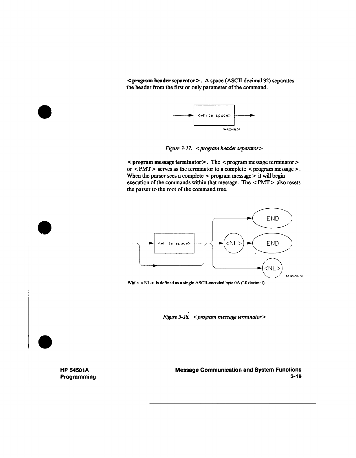
<
program
the
header
header
from the
separator
first
only
or
A
>.
parameter
i
<wh
te
space
space>
(ASCII
of the
decimal
32)
command.
separates
<
program
<
PMT
or
the
When
execution
the
parser
X
——»-
\
<
While
NL>
message
>
serves
parser
the
of
the
to
.
is
defined
Figure
3-17.
terminator
the
as
a complete
sees
commands
the
of
root
a single
as
<
program
The
>.
terminator to
<
within
program
that
command
/
ASCII-encodcd
header
<
program
a complete
message
message.
tree.
OA (10
byte
separator>
message terminator
<
program
it
>
will begin
<
The
PMT
decimal).
message
>
also
>
>.
resets
HP
54501A
Programming
Figure
<
3-18.
Message
program
message terminator
Communication
>
System Functions
and
3-19
Page 62

Message
3-20
Communication
Figure
3-19.
and
System Functions
<
response message
>
Tree
HP
54501A
Programming
Page 63

Device
Talking Syntax
talking
The
listening
easily interpret
more
implications
the
formats.
controller
syntax
syntax.
The
instrument
with
of
This
this
of
spaces.
IEEE
allows
and
use
is
the
will
is
4882
the
programmer
the
data
absence
pad
not
designed
the
instrument
<
of
white
messages
to
to
be
more
write
space
which
precise
routines
is
sending.
>
in
the
being
are
than
which
One
talking
sent to
the
can
of
the
<
response message
the
instrument.
the
<
response
message
<
response
individual
generate
unit
results
>
>
may
from
message
the
to
message
pieces
<
one
generate
>.
is
the
It
complete
a
>
should
instrument.
Figure
unit
a
of
response.
response
multiple <
This
element
result of
<
program
be
3-20.
This
>.
message
a complete
as
serves
the
instrument
message
before
read
<
response message
executing
>.
sending
element serves
Typically
unit
response message
a
although
>,
<
query
The
>
the
as
message
<
a
unit
response
and
complete
another
container
query
>
s.
buffering
<
program
of
>
unit
message
from
will
HP
54501A
Programming
<
response
what
the
header
response
The
>.
data
represents.
Message
<
response
header
Communication
when
>,
and System
returned,
indicates
Functions
3-21
Page 64

Where
<
simple
response
mnenomio
54120/BL58
is
defined as
<response
i
mnemon
c>
Message
3-22
Communication
<
Where
Where
compound response
<
common
Figure
3-21.
and
System Functions
header
<response
i
mnemon
response
<
response message
c>
header
> is
> is
defined
defined
unit
as
as
<response
i
c>
mnemon
54120/BL60
>
HP
54501A
Programming
Page 65

Where
<
response
mnemonic
> is
defined
as
<
Where
decimal).
(65-90
Where
(_)
decimal).
<
response
various
include:
(integer),
data
>,
ASCII
response
uppercase
represents
Figure
data
of data
types
<
character
<
nr3
<
definite
>
alpha
"underscore",
an
3-21.
The
>.
which
response
numeric
length
data
>.
Figure
is
defined
<
response
<
response
the
response
arbitrary
3-22.
single
a
as
a single
ASCII
message
data
instrument
>,
data
<
data
block
<response
mnemonic>
<
character
54120/BL62
byte
>
(continued)
return.
data
data
byte
in
with the
represents
These
response
and
>,
>
ASCII
encoded
encoded
unit
>
element
may
numeric
nrl
>
(exponential), < string
response
response
the
range
value
the
types
data
response
<
arbitrary
41
5F
-
5A
(95
>
HP
54501A
Programming
Figure
Message
3-23.
<
nrl
numeric
response
data
>
Communication and System Functions
3-23
Page 66

<digit>
<digi
t>
Message
3-24
Communication
Figure
3-24.
Figure
and System Functions
<
3-25.
nr3
<
numeric
string
response
response
data
data
>
>
HP
54501A
Programming
Page 67

v
#
<non-zero
t>
digi
—
<d
igi t>
i t
<8-b
dato byte>
<
ASCII
Where
decimal).
The
1.
arbitrary
The IEEE
2.
well as
byte
<
RESPONSE MESSAGE
data
END
message
ASCII
488.1 END
terminating
the indefinite
of
Figure
<
response
response
data
data
within
Figure
3-26.
>
type
represents any
provides
characters.
the
an
message
<
RESPONSE MESSAGE
block
data.
TERMINATOR
<
3-27.
separator
single
a
>.
<
definite length
ASCII-cncoded
the
dual function
is
NL
presented
termination
umambiguous
serves
The
>.
arbitrary
<
ASCII
A
comma
response message
arbitrary
byte
for terminating
is
It
>.
consistency
for
response data
separates
except
element
to an
only
sent
multiple
unit
>.
block
<NL>
this
once
with the
>
pieces
>
(OA.10
that
contains
element
with the last
of
as
HP
54501A
Programming
Figure
Message
<
3-28.
response
Communication
54120/BL69
data
separator
and System
>
Functions
3-25
Page 68

<
response
response
header
header,
separator
if
returned,
>.
from
A
the
space
first
(ASCII
only
or
decimal
piece
of
32)
data.
delimits
the
<
response
<
response message
message
Figure
<
response message
(NL)
terminates
the
from
instrument
If
you
54501A
HP
do
Figure
3-29.
unit
unit
3-30.
terminator
a
complete
along
read
not
will produce
<
response
separator
>
if multiple
s
<
response message
>.
<
response message
with
the
<
the
response
interrupted
an
header
A
semicolon
>.
responses
A
<
response
response
Note
message
separator
delimits the
are returned,
unit
separator
message terminator
should
It
>.
itself.
terminator
on
the
error
>
>
next
>
be
read
the
message.
>
Message
3-26
Communication and System
Functions
HP
54501A
Programming
Page 69

Common
Commands
488.2 defines
IEEE
perform
therefore
instrumentation.
asterisk. There
commands
IEEE
the
traversal
Conventions
functions
be
and
488.2
common
command
can
implemented
tree.
be found
chapter.
is
the
which
All
one
a
set of
common commands.
common
are
a
in
the
common
key
difference between
the
rest of
commands
information about
More
in
the
Programming
to
standard
commands
commands
do
not
any type
across
way
of
found
affect
the
and
the
the
These
commands
of
instrument.
variety
a
wide
begin
488.2
IEEE
488.2
IEEE
this
in
instrument.
parser's
command
Documentation
position
tree
They
of
with
common
The
within
and
tree
can
an
Table
HP 54501A's
3-3.
IEEE 488.2
Common
Command Command Name
*CLS
*ESE
*ESE?
*ESR?
*IDN?
*IST?
*LRN?
*OPC
*OPC?
*OPT?
*PRE
*PRE?
*RCL
*RST
*SAV
*SRE
*SRE?
*STB?
*TRG
*TST?
*WAI
Status
Clear
Event
Event
Event
Identification
Individual
Learn
Command
Status Enable
Enable
Status
Register
Status
Query
Status
Query
Setup
Device
Operation Complete
Operation
Option
Parallel
Parallel
Recall
Reset Command
Save
Sendee
Service
Read
Trigger
Self-Test
Wait-to-Continue
Complete
Identification
Poll
Enable
Poll
Enable
Command
Command
Request
Request
Byte
Status
Command
Query
Enable
Enable
Query
Command
Command
Query
Query
Query
Command
Query
Query
Register
Register
Commands
Enable
Enable
Command
Query
Command
Query
HP
54501A
Programming
Message
Communication
and
System
Functions
3-27
Page 70

Status
Reporting
The
status
serial
the
commands,
instrument
reporting
parallel
and
and
common
defined
features
polls.
bit
structures
which
are
IEEE
488.2
definitions
and bits.
available
defines
for
each.
over
data
There
the
HP-IB
structures,
also
are
include
bits
The
residing
queue
in
event
until
associated
all
is
the
event
enable
the
queues
in
behind
following
be
cleared.
the
status
them.
not
empty.
register
register.
register
commands.
except
<
a
program
is
the
byte
For
is
read
output
act
the
In
registers,
The
set.
Events
cleared.
or
"*CLS"
The
message
as
summary
of
case
the
events
captured
queue.
terminator
bits
queues,
summary
enabled
are
by
an
Registers
command
"*CLS"
If
>,
for
the
summary
bit is
event
are
clears
is
sent
the
the
data
if
set
via
the
register
with their
read
all
event
immediately
output
structures
bit
any
corresponding
remain
queue
if
is
set
enabled
set
registers
will
also
the
bit
and
Message
3-28
Communication
and System
Functions
HP
54501A
Programming
Page 71

,ES;@i
CEHERAT
i
QUEUE
OUTPUT
OT
N
QUEUE
wrr
P
•——
-fi^}.
\
>-
3
—[TO"}*—
MA
®,
^
|
V
)
.
y
1
),
^
i
)
,
1
^
)*
.,
E
a)^—ITRG
(
I
-^—
fl
|
•^—
'/
)
^
101
IN
,
fROST
6 E
~|ussl
\
)
i
————^
SB
J
^
—T?
^
g
^
|
.
—————
————
REXO BY
:LTER?
NOT
OIM
REAO BY
;LE»T
READ
|4—
READ BY
SERIAL POLL
STATUS BYTE REGISTER
READ BY
.STB?
EtPTY
fir
:rER?
MESSAGE
'
°|'
-•"•°°
"I"'
;9YSTEU:DSP?
QUEUE
7
6
^
^
^
c
^
;
^
-(•
]
-L
76543216
|
J
),
i
"I
|
1
),
]
}^
POWER ON
USER
COMMAND ERROR
EXECUTION
DEVICE DEPENDENT
QUERY
REQUEST
OPERATION
r
6
EVENT STATUS REGISTER
)
T
EVENT STATUS ENABLE
SET BY
REQUEST
ERROR
STANDARD
READ
STANDARD
REGrSTER
READ
ERROR
CONTROL
COtfl.ETE
BY
•ESE
BV
-ESR?
<Wf>
•ESE?
ERROR
54501
A
HP
Programming
Figure
3-31.
Status
Reporting
Message
Structures
Data
Communication
and
System
Functions
3-29
Page 72

Bit
Definitions MAY
output
•
message
queue.
available.
Indicates whether
there
is
a
response
in the
•
ESB
event status
Status
Event
•
MSS
master
requesting
for
•
RQS
request
is
bit
returned
a serial
MSG
poll
-
Message.
queue.
•
PON
power
-
URQ
user
-
CME
EXE
command
•
execution
inconsistent
•
DDE
device
complete
an
bit
Register
summary
service.
(MSS is
on.
request.
with
specific
operation
are
service.
during
a serial poll. RQS will
not
Indicates whether
Always
Indicates
error.
error.
current
error.
set
if
any
and
enabled.
Indicates
is
returned for
if
the
by
-STB?).
Indicates
status.
This bit
Indicates
reset
there
0
in the HP
54501A.
whether
Indicates
whether
Indicates whether
settings.
for
Indicates
device
whether
dependent
of the
whether
device
is
a
front
the
a
parameter
conditions
the
*STB?
the
is
requesting
be
set
to
a
message
panel key
parser
the
device
reasons.
the
in
device
query.
service.
0
after
in the
has
detected
out
was
was
Standard
a
has
being
read
message
pressed.
been
an
error.
of
range,
unable
reason
This
via
or
to
Message
3-30
-
QYE
query
violated.
•
RQC
request
54501A
HP
The
-
OPC
operation
pending
LCL
operations.
-
local.
Communication and System
Indicates
error.
control.
will
Indicates whether
never
complete.
request
Indicates
Indicates whether
Functions
whether
control.
a
remote
the
protocol
the device
whether
local transition
to
queries
for
is
requesting control.
the device has
has
has been
completed
all
occurred.
HP
54501A
Programming
Page 73

TRG
•
trigger.
Indicates whether
trigger
a
has
been
received.
Key Features
-
LTF
limit
A
of
few
Operation
which
can
command,
OPC
set the
RQS
the
OUTPUT
OUTPUT
!will
generate
!
acquisition
The
Trigger
trigger.
it
needs
after
If
operation
after each
is
cleared
each
you
The
to
are
test
failure.
the
most
Complete.
be
used to
when
bit
in
bit
have
707;"*SRE
707;":DIG
a
SRQ
is
complete
Bit.
TRG
reading
by
multiple
detect
one.
using
the
the
when
it
time
important
The
find
sent
to
the
Standard
been
enabled,
32;
CHAN1;
when
The
TRG
event
it
Service
trigger
has
been
Indicates
features
IEEE
if
out
any
the
instrument
*ESE
the
bit
indicates
register
using
or
triggers,
Request
is
bit
set.
a
whether
limit
of Status
488.2
structure
after
request
is
the
Register.
an
operation
Event
a
service
1"
!enables
Status
*OPC" iinitiates
if
the
device
will
stay
the
the TRG
to
then
set,
set
*CLS
command.
event
interrupt a
you must
after
test failure
Reporting
provides
finished.
operation
If the OPC
will
be
OPC
service
acquisition,
data
has
receiving
If
register
program or
clear
has
occurred.
shown
are
technique
one
*OPC
The
interest,
of
generated.
request
and
received
a trigger
application
your
be
must
cleared
controller
the
event
below.
will
bit
and
a
until
register
HP
54501A
Programming
next
next
trigger
707;A$!
trigger
707;"*SRE
707;":TER?"!
OUTPUT
!
the
OUTPUT
ENTER
!
the
!SRQ
Status
Byte.
controller
(read
cleared when
serial
*STB?) will
with
If
the
read,
will
generate
clearing
can
now
device
polls
the
except
Message
I"!
enables
queries
it.
generate an
is
requesting
device,
be
not
for
trigger
a
SRQ.
an
the TRG
the
cleared
RQS
the
service
event
service
RQS bit
by
reading it.
bit.
Communication
request.
register,
(RQS set),
is
cleared.
The
and
thus
the
and
The
status
MSS
byte
bit
is
not
System Functions
3-31
Page 74

Serial
Poll
The
serial
the
of
HP
poll
status
54501A
the
of
byte.
supports
instrument
the
IEEE 488.1
is
requested,
serial
the
poll
RQS
feature.
is
bit
When
returned
on
a
bit
6
Serial
Using
conducting
by
assume
address
throughout
Interface
The
Stat
this
Stat
address
into
that
7
and
this
Select
program
=
SPOLL(707).
example.
=
SPOLL(701)
This
7.
the variable called
tested to see
the
poll
interrupts
line.
SRQ
The serial
Enable
1.
SRQ
If
2.
check the
high.
This example will
Poll.
a
serial
there
a printer
two instruments
are
manual,
Code
command
The
The
command
because
command
is
it
if
set
operation can
on
is high
line
instrument
poll
of
address
at
it
and
7.
serial
for
address
the
reads
Stat. At
=
6
(bit
the
bus.
(some
at address
all
instruments
1.
is
also
poll
707 is
checking
for
address
the
that
1).
be
conducted
This
instrument
1
show how
the
on
address
These
assumed
using
HP
the
address
the
of that
contents
bit
time
in the
allows the
is
if bit
to see
to
use
the
on
bus.
bus;
an
assumptions
that
we are
BASIC
of
printer
instrument
of the
HP-IB
6
of
the
following
controller
requesting
6
of
the
service
this
In
oscilloscope
operating
is
4.0
oscilloscope
the
is
is
01
Status
variable
Stat
manner.
"see"
to
service)
its
status
register
request
example,
at
made
are
on
bus
on
Register
be
can
the
then
is
in
Message
3-32
Disable
3.
Communication and
interrupts
System
on
Functions
the
bus.
HP
54501A
Programming
Page 75

To
4.
following
IF BIT
check
(Stat, 6)
whether
command
then
bit
6
line.
of
instruments status
an
register
is high,
use
the
6
bit
If
5.
6.
The
simply
addresses
(serial
of the
instrument
As
rest
soon
of
as
the
SPOLL(707)
reading
the
disable)
poll
at address
the
status
the
talker and
information about
is
set,
language
poll
it
the
programming
the serial
After
Register will
Byte
Register
command, or
cannot generate
instrument
instrument
bits
command
register.
bus
serial poll,
at
7
to
see
with
to
determine
causes
This
listener,
commands,
reference
is
completed, the RQS
it
be
will
instrument
another
if
reset
remain
SRQ.
set
is
address
if
bit
status
command
sends
to
refer
manuals.
was set.
until the
reset.
1
6
what
much
SPE
and
your
Once
If
is
not
its
of
6 high is
bit
is
required.
more
clears
(serial
reads
controller
bit in the
status
these
high,
status
to
the
bit
a
is
bits
cleared
do
check
then
register
found,
happen
the bus,
on
automatically
poll enable)
For
data.
manual,
54501A
HP
in
the Status
with
get
not
the
is
high.
check
the bus
more
and
Byte
a *CLS
reset,
the
and
Status
they
than
SPD
HP
54501A
Programming
Message
Communication and System
Functions
3-33
Page 76

Parallel
Poll
Parallel
poll
information
initiates
data
PPC
a
Parallel
lines.
(Parallel
individually,
combination
any
or
is
result
groups
a logical
of the status bits.
is
a
controller
from
Device
Poll
each
several
Poll,
each
assignments
DIO
Configure)
a
separate DIO
on
these
of
AND
(True
initiated
devices
device
sequence.
two
High)
operation
simultaneously.
a
returns
are
Status
made
Devices
line; collectively
responding collectively,
When
ways.
or
logical
a
which
When
by
the
respond
OR
is
used
to
a
controller
Bit
via
one
controller
either
single
a
on
(True Low)
obtain
the
of
using
DIO
the
of
DIO
the
line;
the
Figure
3-32
in
sent
response
Status)
local
The Parallel
summarized
Poll Register
the *PRE?
used
to read
shows
to
message.
Poll
Enable
in the
Enable)
query
"ist"
the
the Parallel
a
Parallel
Register
individual
command
is
used to
without
Poll
Poll.
status
read
doing a
Data
Structure.
This
summary
determines
local
is
used
to
the
register.
parallel
which
register.
write
The
poll.
bit
to
The
is
events
The
the
*IST?
summary
"ist"
the
are
*PRE
enable
query
is
bit
(Individual
(Parallel
register
can
and
be
Message
3-34
Communication
and System Functions
HP
54501A
Programming
Page 77

REFER
TO
SERIAL
POLL STATUS
REPORTING
UN
TIO
§
<
0
>—i
8
J
r
INDIVIDUAL
READ
BY
iJHHH
••"
7
MSS
ESB MAV
MSG LCL TRG
LTF
1
•*-(&
t
^
^
,
^
5,
/-
•^——
)
'^
s
1
~\
'
p,
1
M
),
i
K
7654.3210
STATUS
«IST?
Figure
3-32.
Parallel Poll
M501/BLZ1
STATUS BYTE
READ
),
;
)
1
PARALLEL POLL
SET
Data Structure.
BY
BY
*PRE
REGISTER
«STB?
<NRf>
HP
54501A
Programming
Message
Communication
and System
Functions
3-35
Page 78

Polling
HP-IB
Devices.
Parallel
devices
Poll
are
programmed
possible
it
makes
device
its
responds
specific
a
If
about
device.
is
the fastest
connected
respond
to
obtain
to
affirmatively
status
to
can
means
the
bus.
with
the
be
gathering
of
Each
bit
one
status
a
to
obtained
device
of
status
of
several
parallel
by
status
device
this
(with
parallel
when
devices
poll,
more
conducting
when several
capability)
polled.
in
one
operation.
information
serial
poll
a
can
of
be
This
the
Configuring
Poll
Responses
Parallel
Certain
by a
programmed
status
can
Multiple listeners
device
separate
Example:
ASSIGN
PPOLL CONFIGURE
The
rounded
least
determine
Bit
A
message
Example: The
interface select
response
PPOLL
devices,
controller
on one
be
programmed
is
©Device
value
significant
3
specifies
ofO
value
is
following
CONFIGURE
including
respond
to
parallel poll
a
for
of the bus
by the
cannot
respond
to
PPC
of Mask
and then used
which
implies
true.
on
statement.
to
707
@Device;Mask
(any
3 bits
data
"true"
the
that the
statement
7
to
is
"true."
respond
707;4
the
to
data lines.
PPC
be
single bit,
a
numeric
configure
to
0
(bits
line the
state
configures
HP
54501A,
parallel
a
responds
The
(Parallel
specified
each device
expression
through
device
the
of
parallel
device's
the
placing a
by
can
poll.
to
response
Poll
this
in
the
device's
2)
the
of
is
respond
to
response
device
0
on
be
remotely
A
device
poll
the
and
Configure)
statement.
must
specified)
be
can
parallel
expression
on
poll
response
0
is
when
at address
DI04
programmed
is
which
by placing
the
data-bit
statement.
If
more
configured
be
response.
are
its
(place
bit
its
status
07
on
its
when
currently
its
current
number
than
is
first
The
used
to
status
the
of
bit
the
status
one
with a
on).
device.
Message Communication
3-36
and System
Functions
HP
54501A
Programming
Page 79

Conducting
a
Parallel
The
8
Poll
the
the
devices
executed
ATNandEOL
PPOLL
status
poll.
(Parallel Poll)
bit
messages
bit
Each
returned
devices(s) configured
respond
can
by
the
controller.
all
for
to
single line).
a
on
function
devices
by
the
function
respond
is
initiated
It
returns
the bus
on
the
to
The
single
a
capable
corresponds
parallel poll
PPOLL
by
the
simultaneous
containing
byte
responding
of
to
(one
function
the
status
or
can
assertion
more
only
up
to
bit
be
to
of
of
Example:
Disabling Parallel
Responses
Examples: The
HP-IB
Commands
Poll
Response
The
=
PPU
capability
the
bus.
following
PPOLL
UNCONFIGURE
This
statement
responding
PPOLL
UNCONFIGURE
If
no primary
responding
specified
disabled.
following
The
used
to
perform
previous
Parallel
examples.
Poll
command
respond
to
PPOLL(7)
(Parallel
disabling
of
statement
disables
parallel
a
to
address
parallel
a
to
devices
paragraphs
the
Unconfigure
(PPU)
parallel
a
Poll Unconfigure)
parallel poll
the
disables
705
all
devices
poll:
8
is
specified,
poll.
(which
functions
If
the
have
describe
of
a
Command.
all
resets
parallel
poll).
statement
response
five
device
interface
on
all
bus
devices
primary
parallel
the
address
poll configure capability)
actual HP-IB
Basic
The
poll
devices
gives
of
one
only:
select
are
is
command
commands
to
poll
the
parallel
the
controller
more
eight
devices
from
from
or
code
disabled
specified, only
which
in the
shown
Unconfigure
idle
state
(unable
the
the
are
can
on
be
to
HP
54501A
Programming
Parallel
(PPC)
parallel
Poll
causes
poll
Configure
the
enable
Command.
addressed listener
secondary command
Message
parallel poll configure
The
configured according
be
to
PPE.
Communication
and System
command
the
to
Functions
3-37
Page 80

Parallel
command
command
particular
a
with
Poll
(PPE)
to
Enable
configures
respond
level.
Command.
the devices
parallel poll
a
to
The
parallel
which
a particular
on
poll
have
enable
received
HP-IB
secondary
PPC
the
DIO
line
Command
Parallel
Poll
(Multiline
Parallel
(Secondary
Parallel
(Secondary
Parallel
(Secondary
Poll
Poll
Poll
Unconfigure
Command)
Configure
Command)
Enable
Command)
Disable
Command)
Parallel
command
command
Table
Poll
Disable
(PPD)
from
3-4.
Mnemonic
Command.
disables
responding
Parallel
Poll
PPU
PPC
PPE
PPD
The
devices which
the
parallel
to
Commands
Decimal
Code
96-111
Parallel
poll.
21
05
112
Poll
have
disable
received
ASCII/ISO
Character
NAK
ENQ
1-0
P
secondary
PPC
the
Message
3-38
Communication
and System
Functions
54501A
HP
Programming
Page 81

Programming
and
4
Documentation
Introduction
Truncation
Rules
This
instrument,
This chapter
command tree traversal.
to
The truncation
arguments
The
This
characters.
Conventions
section
the
rule
covers conventions
well
as
contains
is:
fourth
will
"Message
not
chapter
mnemonic
The
characters
as
conventions used
a
detailed
Communication
the
for
rule
is
first
the
character
keyword.
the
of
be
used
For
four characters
if
which
description
information
more
mnemonics
is
a
vowel,
length
the
are
in
used
then
the
of
used
the
remainder
of
System
and
in
the
of
the
keyword
programming
in
of
the
command
command syntax
on
Functions."
headers and
keyword
mnemonic
is
exactly
this
tree
alpha
unless:
is
the
the
manual.
and
refer
first
three
four
HP
54501A
Programming
Some
shown
are
examples
in
table
the
how
of
4-1.
Table
Longfonn
RANGE
PATTERN
TIME
DELAY
Programming
truncation
4-1.
rule
Mnemonic Truncation
Shortform
and Documentation Conventions
is
applied
RANG
PATT
TIME
DEL
various
to
commands
4-1
Page 82

.(root)
*CLS
*ESE
•ESR
*IDN
-1ST
*LRN
-OPC
<OPT
«
'•
ppr
nr\L
»RCL
*RST
*SAV
*SRE
•STB
«TRG
•TST
<WAI
Common
Commands
(IEEE
This
instrument
identical
through
AUT
oscoIe
BEE
Per
Nk
BLA
DIG
ITize
EOI
ERA
ep
1 F R
LTER
MENU
MERGe
PRINt
RUN
i
1
SER
a
STOP
STORe
VTFW
•1[-
Root
Comn
488.2)
contains four identical
function subsystems.
4.
and the
Function
System:
DSP
ERRor
HEADer
KEY
LONGform
SETup
Leve
onds
header must
1
The
Figure
ACQuire:
COMPIete
COUNt
POINts
TYPE
channel
"N"
in the Channel
be
The HP
4-1.
1
or
•'--"'
CAL
TNUL
subsystems
header
Z.
54501A
ibrote:
1
and two
must
Command
CHANneKN>:
1 i
COUP
ng
ECL
HFRe
ject
OFFSet
PROBe
RANG
e
TTL
1
be
Tree
DISPlay:
COLu
mn
CONN
ect
DATA
FORM
ot
i
GRAT
INVe
rse
LINE
WSK
i
PERS
KUW
SCRe
en
auUKce
^^"S
1
ILX
TMARker
VMARker
cu Ie
stence
FUNCtion<
ADD
INVert
MULTiply
OFFSet
ONLY
RANGE
SUBTract
VERSUS
54501S30
Programming
4-2
and Documentation Conventions
HP
54501A
Programming
Page 83

HARDcopy:
LENGth
PAGE
MEASure:
ALL
COMPore
CURSor
DEF
ine
DELoy
DEST
motion
DUTycycle
ESTArt
ESTOp
FALLtime
FREOuency
LIMi
ttesi
LOWer
MODE
NWIDth
OVERshoot
PERiod
POSTfoi
PRECis
PREShoot
PWIDth
RESults
RISet
SCRatch
SOURce
STATistics
TDELta
TMAX
TMIN
TSTArt
TSTOp
TVOLt
UNITs
UPPer
VAMP
VAVerage
VBASe
VDELta
VFIFty
VMAX
VMIN
VPP
VRELoti
VRMS
VSTAr
VSTOp
VTIMe
VTOP
I i
i
ime
tude
t
lure
on
ve
TIMebose:
DELoy
MODE
RANGe
REFerence
WINDOW
WINDOW:
DELay
RANGe
TRIGger:
CONDilion
DELoy
DELoy:
SLOPE
SOURce
FIELd
HOLDoff
I
LEVe
LINE
LOGic
MODE
Occurrence
OCCur
rence:
SLOPe
SOURce
PATH
i
POLar
ty
i
OUAL
fy
SLOPe
SOURce
STANdard
WAVeform:
COUNt
DATA
FORMat
POINts
PREamble
SOURce
TYPE
XINCrement
XORig
in
XREFerence
YINCrennent
i g i
YOR
n
YREFerence
HP
54501A
Programming
Figure
4-1.
The HP
54501A
Programming
Command
(continued)
Tree
and Documentation
Conventions
4-3
Page 84

The
Command
Tree
The
command tree
relationship
the
and
common
do
affect
not
(linefeed
will
be
set
(figure
of
commands
-
ASCII decimal
the
to
the
are
position
"root"
4-1) shows
the
commands
listed
not
the
of
10)
the
of
as
part
parser
has
been sent
command
all
commands
to
each
the
of
within the
to
tree.
in
The IEEE 488.2
other.
command
tree.
the
instrument,
HP
the
tree
After
54501A
since
<
a
NL
the
they
>
parser
Command
Types
The
commands
types
three
Common
do
and
from
back
not
root
at the
Example:
Level
Root
command
beginning
Example:
Subsystem
a
under
common
this
for
are:
commands.
affect
level
root.
Common
position
the
commands
»RST.
commands.
These
tree.
a
of
commands
program
:AUTOSCALE
commands.
node
instrument
commands
of
in that
The
root
message,
Subsystem
the
of
tree,
be
can
the
parser
level
root
level
commands
always parsable
are
preceded
or are
commands
such
as
placed
into
independent
are
within
commands
by
are
TIMEBASE
the
three
the
tree.
place
reside
if
they
a
colon.
grouped
types.
the
of
These
the
the
at
root
occur
together
commands.
The
tree,
differ
parser
of
the
at
the
Programming
4-4
and Documentation
Conventions
HP
54501A
Programming
Page 85

Tree Traversal
Rules
Command
legal
headers
command
are
header
created
from
":CHANNEL1:RANGE".
is
compound
by
colons.
apply
traversing
to
header
The
a
header
mnemonic
the
tree:
by
the
command tree
is
This
made
created
traversing
referred
of
two
contains
the
down
figure
in
a
to as
compound header.
or more
mnemonics separated
no spaces.
command
4-1 would
following
The
tree.
be
A
A
rules
Examples
Example
Comments:
1:
A
•
leading
<
>
NL
or
the
command
character
• Executing
leading
colon
Command
header
last
parser
current
appear
as
colon
will
program
above
The OUTPUT
200/300
Series
a
followed
by
colon
EOI
a
of
a subsystem
Tree,
a
reference
above
be.
statements
Controller.
carriage
<
a
or
program
last
on
A
leading
header.
the
true
tree.
program
command
<
a
or
program
figure
that
Any command
message
them (OFFSET).
return
use
4-1,
(for
point
mnemonic
below
without
written
are
quoted
The
linefeed (CRLF).
and
message
byte)
colon
message
the
example,
(CHANNELl:),
OUTPUT 707;":CHANNEL1:RANGE
The
between CHANNELl
colon
CHANNEL1:RANGE
the
RANGE
<
program
CHANNELl
need
command
command
message
the
set
unit
preceding it,
parser to
is
a compound
and
separator
and
OFFSET
the
>.
since
the
CHANNELl node
terminator
places
the
is
a
colon
places
you
in
terminator
last
mnemonic
RANGE).
point
that
sending
using
string
RANGE
command.
The OFFSET
HP BASIC
is
;OFFSET
0.5
command
the
placed
is
> (either
at
parser
is
that
the
first
subsystem
that
> is
found).
compound
in
the
Then
that
and
be
sent
can
mnemonic(s)
4.0
on
bus,
the
on
0"
necessary,
The
semicolon between
is
the
required
command
the
is
a
the CHANNEL1:RANGE
in
the
tree.
a
of
root
(until
the
In
find the
where
within the
which
9000
HP
does
not
a
the
HP
54501A
Programming
Programming
and
Documentation
Conventions
4-5
Page 86

Example
2:
OUTPUT
or
707;":TIMEBASE:REFERENCE
CENTER
;DELAY
0.00001"
Comments: In
Example
Comments:
Infinity
ReDresentation
OUTPUT
OUTPUT
the
DELAY
The
REFERENCE
will place
A
second
the
DELAY
3:
OUTPUT
The
the
command
command.
The
returned
707;":TIMEBASE:REFERENCE
707;":TIMEBASE:DELAY
first
command
DELAY
the
way
leading
representation
when
example
line
of
in the
command
must
command,
back
parser
to send
command
these
as
707;":TIM:REF
before
colon
The
tree.
a
parser
infinity
of
measurement
the
2,
compound
be
because
the
at
commands
shown
CENTER
CHAN1
can
is
0.00001"
"subsystem
command.
in the
same
<
the
program
the
of
root
in
example
tells
then
command
is
by
:CHAN1:OFFSET
;
the
parser
see
9.99999E+37.
be
cannot
made.
CENTER"
selector"
program
placing
2.
the
is implied
message
message
tree.
"TIMEBASE:"
back
to
go
CHAN1:OFFSET
is
This
also
for
the
as
terminator
0"
the
to
the
value
the
>
before
of
root
Programming
4.6
and
Documentation
Conventions
HP
54501A
Programming
Page 87

Sequential
Overlapped
Commands.
and
IEEE 488.2
commands.
the
next command starts. Overlapped commands
therefore
before
HP
the
the
54501A
overlapped
the distinction
makes
Sequential
command
sequential.
are
commands
following
command
between
finish
overlapped
an
is
completed.
sequential
their task
All
and
overlapped
the
before
execution
run concurrently,
command
the
commands
may
be
of
and
started
of the
Response
Generation
Notation
Conventions
Definitions
and
488.2
IEEE
The first
the
response.
is
The
remote
< >
symbolize
=
::
can
|
< A > | < B >
...
may
is
when
controller
The
parsed.
following
(HP-IB)
Angular
a
"is
defined
be
replaced
"or." Indicates
ellipsis
An
be
repeated one
[ ] Square
defines
program
two
the
query
addresses
54501A
HP
conventions
operation:
brackets
as."
For
< B >
by
a
choice
indicates
(trailing dots)
brackets
indicate
times at
is
parsed by
the
instrument to
will
buffer
used
are
enclose words
code
parameter or
example,
in
any
of
one
< A >
is
used
or more
times.
that the
which
query
the
instrument,
talk
responses
this
in
manual
characters
or
an HP-IB
<A>::=
statement
element from
or
containing
< B >
but
indicate that the
to
enclosed
responses
it
that
so
a
to
query
descriptions
in
that
command.
indicates
<B>
a
list.
For
not
both.
items
are
be
may
the
second
read
may
when
used to
are
< A
>.
example,
preceding
optional.
buffered.
is
when
the
the
query
of
<
that
element
A
>
HP
54501A
Programming
{ }
When several
elements
must
items
be
selected.
enclosed
are
Programming
by
braces,
one,
and
only
and Documentation
of these
one
Conventions
4-7
Page 88
The
following
= A
d::
= A
n::
definitions
single
ASCII
single
ASCII
used:
are
numeric
non-zero,
character,
numeric
0-9.
character, 1-9.
Syntax
Diagrams
<
NL
<sp>
<
white
beginning
the
At
circle
or
and
command
the
arrow
around it.
a
many
the
other
showing
a
Words
the
command.
by
arguments
direction
path
"space"
in
=
>
::
::=
space
of each
proper
oblong
phrases
and
line
Each
the
on
that
can
is
syntactically
Where
white
space character
places.
Newline
<
white
>
::
syntax
literals,
are
contained
described
are
can
entry
generated
be
there
Linefeed
or
>
space
=
0
through 32 (decimal)
(decimal
following
of the
for each
and
in
only
be
line.
Any
correct.
is
a
must
(ASCII
10).
command.
be
must
rectangles
accompanying
the
in
entered
combination
following
by
An
argument
rectangle
be
entered.
decimal
chapters
All
entered
are names
from
one
the
is optional if
which
10).
except
syntax
are
characters
exactly
of items
text
direction
of
commands
lines in the
contains
White
space
linefeed
diagrams
contained
as
shown.
used
of
each
indicated
as
and
proper
there
the
word
is
with
is
a
optional
in
Programming
4-8
and
Documentation
Conventions
HP
54501A
Programming
Page 89
Command
Structure
The
common
54501A
HP
commands, root
programming
programming
level
command tree
commands
commands,
is
shown
in
are
and
figure
divided
subsystem
4-1.
into
three types:
commands.
A
Common
Commands
ROOt L6Vel
Commands
Subsystem
Commands
The
common
These
commands
488.2
instruments.
instrument out
root
root
When
sent
the
are
level
several
the
of
a
in
root
a
The
instrument.
There
be selected at
the
commands
of
commands
any
command
program message
program
of
the
are
control
a
Sending
selected
some
the
subsystem.
control
subsystems in
given
time.
tree,
message,
command
the
commands
functions
common
many
this
At
power
therefore
Note
terminator
the
command
tree
defined by
that
are
commands
basic
of
the
instrument.
the
on,
subsystem
no
a
or
common
do
functions
Only
command
leading
is
parser
IEEE
to
take the
not
subsystem
one
parser
is
selected.
colon
returned
488.2.
all
of
(:)
IEEE
the
is
is
to
set
may
to
HP
54501A
Programming
Programming
Documentation Conventions
and
4-9
Page 90

The
11
subsystems
in
the
HP 54501A
are:
System
Acquire
-
controls
-
Calibrate
Channel
Display
graticule,
-
-
Function
Hardcopy
waveforms.
Measure
-
Timebase
Trigger
-
controls
mode.
the
sets
-
the
sets
controls
controls
and text
-
controls
-
controls
selects
-
controls
basic
some
parameters
nulls
time
all
Y-axis
how
waveforms,
displayed
are
the
waveform
the
parameters
the
automatic
all
X-axis
trigger
the
oscilloscope.
of
functions
acquiring
for
the
and
(channel-to-channel
oscilloscope
and
math
voltage
written
functions of
used
functions.
and
on
during
measurements
oscilloscope
modes
and
parameters
functions.
storing
skew).
time
the
screen.
the
be
to
data.
markers,
oscilloscope.
the
printing
made.
each
for
of
trigger
Waveform
from
memories.
Programming and Documentation
4-10
-
provides
channels and
Conventions
access
functions
to
waveform data,
static
well
as
as
including
data
from
data
active
waveform
HP
54501A
Programming
Page 91

Program
Examples
The
program
appendices
and
using
the HP
assume
assumed
examples given
BASIC
oscilloscope
the
be
to
at
written
were
4.0 programming
is
at
address
701.
each
for
on
address 707.
an
command
9000
HP
language.
If
Series
printer
a
in the
200/300
The
following
controller
programs
is
used,
it
always
is
chapters
always
examples,
these
In
the
command/query
respond
a command/query
to
command/query.
longform
or
command/query
both
letters,
form
that
l.OE-1),
As
wish.
you
value could
a
or
an example,
special
can
That is, the
shortfonn
using
the
work
If
you
be
sent
(100
suffix
set
channel
be
if
one
upper
same.
were
using a
mV
following:
•
commands
OUTPUT
•
commands
longform
in
707;":CHANNEL1:RANGE
in
shortfonn and
OUTPUT 707;":CHAN1:RANG
•
commands
OUTPUT
using
lower case letters,
707;":chanl:rang 100
has
should be
The
way
bearing
no
attention
sent.
command/query
exists
for
(capital)
case
the
Also,
sending
data
a
channel
decimal
100MV).
or
1
and
range
using
using
to
the decimal
mV
paid
the
instrument
on
can
that
command.
letters
be
can
1
(.1),
or an
100
by
mV
.1"
exponential
an
1E-1"
shortforms,
the
to
how
you
be
sent
lower case
or
using
sent
value
range
exponential
sending
format.
format.
and
ways
is
send
You
one
a
set
using
can
almost
of
of
suffix.
which
in
to
up
the
the
send
(small)
any
100
mV,
(le-1 or
the
the
HP
54501A
Programming
examples, the
these
In
command
argument
is
optional.
is
required.
Programming
colon as
The
space
Note
first
the
between
character
RANGE
of
the
and
the
and Documentation Conventions
4-11
Page 92
If
you want
returned
string
variables
to observe
into
data
before
string
a
the
headers for
variable.
reading
the
the
Generally,
data.
queries,
you
must
you
should
bring
the
dimension
all
Command
Set
Organization
do
If
from
the
The
Common
commands.
you
the
headers
command
not need
54501A,
HP
should be
set
commands, root
Each of
following chapters.
in the
a
set of
that
for
longform
AUToscale
subsystem,
commands
shown
As
an example,
AUTOSCALE and
listing
command
arguments,
Table
4-2
with
their
contains
the
command syntax,
lists
the
corresponding subsystem
commands
the
to
see
then
turned off.
the
HP
for
level
13
the
of
Each
diagrams
syntax
subsystem
and shortform
the
shortform of
a
headers and
should
you
54501A
commands
of
groups
chapters
the
alphabetic
in
indicates
description
and
the
for
or
a
numeric value
a
numeric variable.
use
is
divided
and
commands
contain
those
for
order.
using
upper
that
the
the
command
the
of
a
programming example.
54501A
HP
command
13
into
11
sets
is
described
a
brief
commands,
The
and
lowercase
longform
is
AUT.
command
alphabetical
in
type.
is
returned
In
separate
subsystem
of
in the
description
finally,
and
commands
the
of
command
Each
its
and
this
case
groups:
of
the
are
letters.
order
the
is
Programming
4-12
and
Documentation
Conventions
HP
54501A
Programming
Page 93

Command
Table
When!
4-2.
Used
Alphabetic
Command
Command
Cross-Reference
Where Used
ADD
ALL
AUToscale
BEEPer
BLANk
•CLS
COLumn
COMPare
COMPlete
CONDition
CONNect
COUNt
COUNt
COUPling
CURSor
DATA
DATA
DEFine
DELay
DELay
DELay
DELay:SLOPe
DELay:SOURce
DESTination
DIGitize
DSP
DUTycycle
ECL
EOI
ERASe
Level
Level
Level
Level
Subsystem
Level
Subsystem
Subsystem
Command
Command
Command
Subsystem
Subsystem
Subsystem
Subsystem
Subsystem
Subsystem
Subsystem
Subsystem
Subsystem
Subsystem
Subsystem
Subsystem
Subsystem
Subsystem
Subsystem
Command
Subsystem
Subsystem
Command
Command
FUNCtion
MEASure
Root
Root
Root
Common Command
DISPlay Subsystem
MEASure
ACQuire
TRIGger
DISPlay Subsystem
ACQuire
WAVefonn
CHANnel
MEASure
DISPlay Subsystem
WAVefonn
MEASure
MEASure
TIMebase
TRIGger
TRIGger
TRIGger
MEASure
Root
SYSTem
MEASure
CHANnel
Root
Root Level
ERRor
•ESE
•ESR
ESTArt
ESTOp
FALLtime
PIELd
FORMat
FORMat
FREQuency
GRATicule
HEADer
HFReject
HOLDoff
•IDN
INVeise
INVen
•1ST
KEY
LENGth
LER
LEVel
LIMittest
LINE
UNE
LOGic
LONGfonn
LOWer
•LRN
LTER
SYSTem
Common Command
Common Command
MEASure
MEASure
MEASure
TRIGger
DISPlay
WAVefonn
MEASure
DISPlay Subsystem
SYSTem
CHANnel
TRIGger
Common Command
DISPlay
FUNCtion
Common
SYSTem
HARDcopy
Root
TRIGger
MEASure
DISPlay
TRIGger
TRIGger
SYSTem
MEASure
Common
Root Level
Subsystem
Subsystem
Subsystem
Subsystem
Subsystem
Subsystem
Command
Subsystem
Level
Subsystem
Subsystem
Subsystem
Subsystem
Subsystem
Command
Subsystem
Subsystem
Subsystem
Subsystem
Subsystem
Subsystem
Subsystem
Subsystem
Command
Subsystem
Subsystem
Command
HP
54501A
Programming
Programming
and Documentation
Conventions
4-13
Page 94

Command
Table
4-2.
Where Used
Alphabetic
Command
Cross-Reference (Continued)
Command
Where
Used
MASK
MENU
MERGe
MODE
MODE
MODE
MULTiply
NWIDth
Occurrence
OCCurrence:SLOPe
OCCurrence:SOURce
OFFSet
OFFSet
ONLY
•OPC
•OPT
OVERshoot
PAGE
PATH
PERiod
PERSistence
POINts
POINts
POLarity
POSTfailure
•PRE
PREamble
PRECision
PREShoot
PRINt
DISPlay Subsystem
Root Level
Root Level
MEASure
TIMebase
TRIGger
FUNCtion
MEASure
TRIGger
TRIGger
TRIGger
CHANnel
FUNCtion
FUNCtion
Common Command
Common
MEASure
HARDcopy
TRIGger
MEASure
DISPlay Subsystem
ACQuire
WAVefonn
TRIGger
MEASure
Common
WAVefonn
MEASure
MEASure
Root
Command
Command
Subsystem
Subsystem
Subsystem
Subsystem
Subsystem
Subsystem
Subsystem
Subsystem
Subsystem
Subsystem
Subsystem
Command
Subsystem
Subsystem
Subsystem
Subsystem
Subsystem
Subsystem
Subsystem
Subsystem
Command
Subsystem
Subsystem
Subsystem
Level Command
PROBe
PWIDth
QUALify
RANGe
RANGe
RANGe
•RCL
REPerence
RESults
RISetime
ROW
•RST
RUN
•SAV
SCRatch
SCReen
SERial
SETup
SLOPe
SOURce
SOURce
SOURce
SOURce
•SRE
STANdard
STATistics
•STB
STOP
STORe
STRing
CHANnel
MEASure
TRIGger
CHANnel
FUNCtion
TIMebase
Common Command
TIMebase
MEASure
MEASure
DISPlay Subsystem
Common Command
Root Level Command
Common
MEASure
DISPlay
Root
SYSTem
TRIGger
DISPlay Subsystem
MEASure
TRIGger
WAVefonn
Common
TRIGger
MEASure
Common
Root
Root Level Command
Display
Subsystem
Subsystem
Subsystem
Subsystem
Subsystem
Subsystem
Subsystem
Subsystem
Command
Subsystem
Subsystem
Level
Subsystem
Subsystem
Subsystem
Subsystem
Command
Subsystem
Subsystem
Command
Level
Subsystem
Subsystem
Command
Subsystem
Command
Programming
4-14
and Documentation
Conventions
HP
54501A
Programming
Page 95
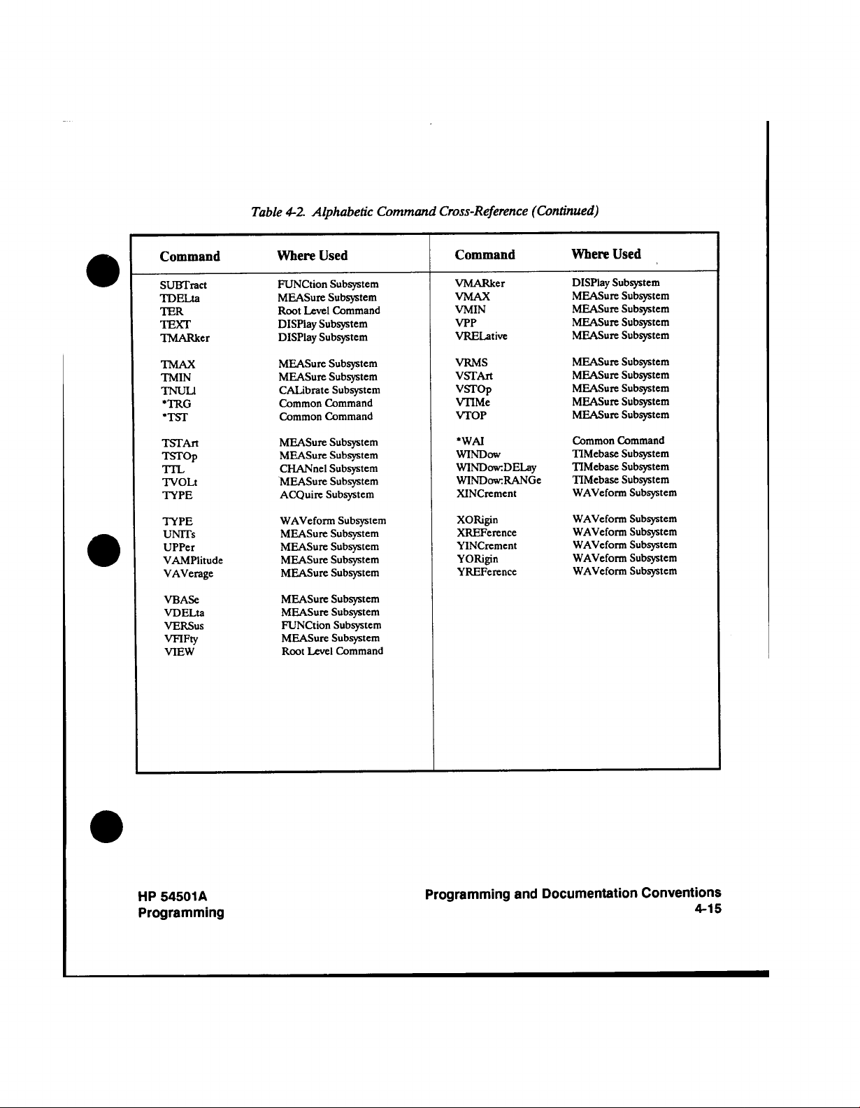
Table
4-2.
Alphabetic
Command
Cross-Reference (Continued)
Command
SUBTract
TDELta
TER
TEXT
TMARker
TMAX
TMIN
TNUL1
•TRG
•TST
TSTArt
TSTOp
TTL
TVOLt
TYPE
TYPE
UNTTs
UPPer
VAMPlitude
VAVerage
VBASe
VDELta
VERSUS
VFIFty
VIEW
Where
Used
FUNCtion
MEASure
Root Level Command
DISPlay Subsystem
DISPlay
MEASure
MEASure
CALibrate
Common
Common
MEASure
MEASure
CHANnel
MEASure
ACQuire
WAVeform
MEASure
MEASure
MEASure
MEASure
MEASure
MEASure
FUNCtion
MEASure
Root Level
Subsystem
Subsystem
Subsystem
Subsystem
Subsystem
Subsystem
Command
Command
Subsystem
Subsystem
Subsystem
Subsystem
Subsystem
Subsystem
Subsystem
Subsystem
Subsystem
Subsystem
Subsystem
Subsystem
Subsystem
Subsystem
Command
Command
VMARker
VMAX
VMIN
VPP
VRELative
VRMS
VSTArt
VSTOp
VTIMe
VTOP
•WAI
WINDOW
WINDowDELay
WINDowRANGe
XINCrement
XORigin
XREPerence
YINCrement
YORigin
YREPerence
Used
Where
Subsystem
DISPlay
MEASure
MEASure
MEASure
MEASure
MEASure
MEASure
MEASure
MEASure
MEASure
Common Command
TIMebase
TIMebase
TIMebase
WAVeform
WAVeform
WAVeform
WAVeform
WAVeform
WAVeform
Subsystem
Subsystem
Subsystem
Subsystem
Subsystem
Subsystem
Subsystem
Subsystem
Subsystem
Subsystem
Subsystem
Subsystem
Subsystem
Subsystem
Subsystem
Subsystem
Subsystem
Subsystem
HP
54501A
Programming
Programming
and
Documentation
Conventions
4-15
Page 96

Common
Commands
5
The
common
commands
standard.
instrument
string,
how
received and
Common
whether
within
other
selected and
instrument
program
received
and
type,
other
type
example
commands
will
be
They
control
identification
status
processed
commands
they
are
program messages.
a
common
will
remain
message
by
the
instrument,
the
clear
of
command
the
program
:ACQUIRE:TYPE
autoscale,
again
sent
Refer
to
Each
enable
you
complete
to
use
to
then
in
order to
figure
of the
(mask)
select the
can
the
chapter
set
5-1
discussion
status
3.
defined
are
all
to
the
of
reset,
cleared,
the
instrument.
received
the
HP-IB as
instruments
reading
If
an
is
common
is
read and
can
sent
over
in
some
and
by
be
command
the selected
"ACQUIRE:COUNT
the
instrument
status
information.
received
were
message
AVERAGE"
the acquire
reenter
for
common
":ACQUIRE:COUNT
would
type.
acquire subsystem
the
commands
Note
registers
status
register. By
status
information
mentioned
setting
information
of
how to
read
available
by
the
basic
instrument
and how
processed
and
separate
instrument
received
subsystem.
1024;
will
This
within
the
set
this
In
syntax
in
bits
the
you
the
from
IEEE 488.2
comply
that
functions,
the
by the
*CLS; TYPE
would
the
acquire
example
this
in
wish
status
(instrument
learn
commands
by the
program
subsystem
instrument,
For
example,
acquire
set the
be
not
program message.
1024;
count,
:ACQUIRE
and
diagram.
chapter
the
enable
to
use.
registers
this
instrument
standard. These
this
with
such
as
setup)
queries
and
54501A
HP
messages
has
AVERAGE"
count
the
case
been
the
if
the
if
are
or
is
and
some
For
:AUTOSCALE;
complete
set
the
has
register
For
and
an
a
type.
how
refer
must
the
be
HP
54501A
Programming
Common
Commands
5-1
Page 97

Common
5-2
Commands
Figure
5-1.
Common
Commands
Syntax
Diagram
HP
54501A
Programming
Page 98

mask_arg
corresponding
mask
commands
=
for
An
bit
integer,
0
to conditions
definitions
through
in
the
255.
that
enable
This
enabled.
are
registers.
number
is
the
Refer
sum
to
the
all
of
*ESE
the
and
bits
*SRE
in the
=
integer,
mask_value
corresponding
mask
An
recall_buffer_number
save_buffer_number
Figure
5-1.
conditions
to
=
An
=
An
Common
0
through
integer,
integer,
This
255.
that
are
0
through
1
through
enabled.
Commands
number
is
Refer
4.
4.
Syntax
Diagram (continued)
the
sum
to the
all
of
*IST?
bits
the
query.
in
the
HP
54501A
Programming
Common
Commands
5-3
Page 99

*CLS
*CLS
Command
Syntax:
Example:
the
Status)
(clear status)
*CLS
including
the
Request-for-OPC
*CLS
command
(Clear
The
structures,
clears
If
TERMINATOR,
will
be
cleared.
-CLS
OUTPUT
707;"*CLS"
Refer
chapter
to
the
immediately
the
output
3
for a
common
defined
device
flag.
queue
complete
command clears
error
queue.
and
a
PROGRAM
the
MAV
follows
Note
discussion
of
the
status
This
(message
status.
command
data
command
MESSAGE
available)
also
bit
Common
5-4
Commands
54501
A
HP
Programming
Page 100

*ESE
*ESE
Command
Syntax:
Example:
(Event
The
The Standard
bits
Standard
in the Standard
table
Register bits,
The
Status
*ESE
command
be enabled
to
Event
for
5-1
*ESE
query
Event
in the
Status Enable
Event
the
information about
bit
weights,
returns
*ESE<mask>
Where:
=
>
<
mask
OUTPUT 707;"*ESE 64"
this
In
6
bit
front
Register
0
::
to
255
example, the *ESE
the
of
Standard
panel key
will
is pressed,
be
also
Enable)
sets the
Status Enable
Status
Event
set.
Standard
Standard
Register, a
and what
the
current
64
command
Status
the
Register
Event
Register
the
each
contents
Enable
(event
ESB
Status Enable
Event
contains
Status
will
enable
will
zero
Standard
bit
masks.
of
will
enable
Register.
summary
command/query
Register
a
mask
value
Register.
Event
the
A
one
the corresponding
disable
the
Status
register.
(user
URQ
Therefore,
bit)
in
the Status
bit.
Enable
request)
when
for
the
in
Refer
bits.
the
bit
to
a
Byte
HP
54501A
Programming
Common
Commands
5-5
 Loading...