

Page 1

W.J.
SERVICE MANUAL
fiORD
l
2111lRkET
P.O.
Box
TELEPHONE(813)
SUIiIPbUS
DIVISION
ST.
606.
SMITHS
Of3125611
N.
(comer
~~
ENTERPRIS
CANlDllNC.
1IalUt'
FALLS,
S5
ONT.
FAX
(613)
ES
W11ti1!!lJ
K7Am
.~
mg
HEWLETT
PACKARD
Page 2

r/l;'
~~PACKARD
HEWLETT
W.J.
SERVICE MANUAL
TELEPHONE
HP 54201A/D
FORD
A
DIVISIONOF3125651
21
MARKET
P.O.
Box
SURPLUS
ST.N.(corner
60S,
SMITHS
(613)
FALLS,
283-5195
ENTERPRISE'
CANADA
MarketIrWillilm)
FAX
ONT.
(613)
INC.
K7A
4T1
283-06
DIGITIZING
SERIAL
This manual applies directly to
instruments
For additional
INSTRUMENTS COVERED BY
important
with
HP 54201A; 2602A
Hp
OSCILLOSCOPE
NUMBERS
serial
number
54201 D; 2602A
information
MANUAL
prefixes:
about
serial
in Section I.
numbers,
see
@ COPYRIGHT HEWLETT·PACKARD COMPANY/COLORADO SPRINGS DIVISION 1986
1900 GARDEN OF THE GODS ROAD,COLORADO SPRINGS, COLORADO U.S.A
Manual Part No. 54201-90902
Microfiche
Part No. 54201-90802
ALL RIGHTS RESERVED
PRINTED:
JANUARY
1986
Page 3
SAFETY
This product has been designed and tested according to international Safety Requirements. To ensure
safe operation and to
must be heeded. Refer to Section i and the Safety Summary for general safety considerations
applicable to this product.
keep {he product safe, the information, cautions, and warnings in this manual,
This apparatus has been designed and tested in accordance with IEC publication
requirements for electronic measuring apparatus, and has been supptiea in
manuai contains some information and warnings which have to be tottowea by the user to ensure safe
operation and to retain the apparatus in safe condition.
CERTIFICATION
Hewtett-Peckert: Company certifies that this product met its published specifications at the time of
silipment from tile factory. Hewlett-Packard further certifies that its calibration measurements are
traceable to the United States National Bureau of Standards, to the extent euowea by the Bureau's
caiibration facility, and to the calibration facilities of other Internationat Standards Organization
members.
a safe condition. This
348, safety
WARRANTY
This Hewlett-Packard product is warranted against defects in material and workmanship
period of one year from date of shipment. During the warranty period, Hewlett-Packard Company
will, at its option, either repair or replace products which prove to be defective.
For warranty service or repair, this product must be returned to a service facility designated by HP.
However, warranty service for products installed by HP and certain other products designated by
HP will be performed at Buyer's facility at no charge within the HP service travel area. Outside HP
service travel areas, warranty service will be performed at Buyer's facility
agreement and Buyer shall pay HP's round trip travel expenses.
For products returned to HP for warranty service, Buyer shall prepay shipping charges to HP and
HP shall pay shipping charges to return the product to Buyer. However, Buyer shall pay all
shipping charges, duties, and taxes for products returned to HP from another country.
only
upon HP's prior
for
a
LIMITATION OF WARRANTY
The foregoing warranty shall not apply to defects resulting from
maintenance by Buyer, Buyer-supplied software or interfacing, unauthortzed modification
misuse, operation outside of the environmental specifications for the product, or Improper site
preparation or maintenance.
NO OTHER WARRANTY IS EXPRESSED OR IMPLIED. HP SPECIFICALLY DISCLAIMS THE
IMPLIED WARRANTIES OR MERCHANTABILITY AND FITNESS FOR A PARTICULAR PURPOSE.
EXCLUSIVE REMEDIES
THE REMEDIES PROVIDED HEREIN ARE BUYER'S SOLE AND EXCLUSIVE REMEDIES. HP
SHALL NOT BE LIABLE FOR ANY DIRECT, INDIRECT, SPECIAL INCIDENTAL, OR
CONSEQUENTIAL DAMAGES, WHETHER BASED ON CONTRACT, TORT, OR ANY OTHER LEGAL
THEORY.
imp~oper
or .inadequate
or
ASSISTANCE
Product maintenance agreements and other customer assistance agreements are avaiiabie for
Hewlett-Packard products.
For any assistance, contact your nearest Hewiett-Packard Sales and Service Office. Addresses are
provided at the
back of this
manuai.
SCWA984
Page 4
UP
54201A/D SERVICE MANUAL
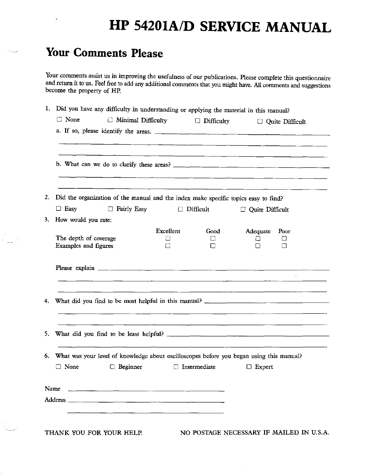
Your
Your comments assist us in improving the usefulness of our publications. Please complete this questionnaire
and return it to us. Feel free toadd any additionalcomments that you might have. All comments and suggestions
become the property
I.
2. Did the organization of the manual and the index make specific topics easy to fmd?
3. How would you rate:
Comments Please
of
HP.
Did you have any difficulty in understanding or applying the material in this manual?
o None
a. If so, please identify the
b. What can we do to clarify these areas? _
DEasy
The
depth of coverage
Examples
and
o Minimal Difficulty
areas.
0 Fairly Easy 0 Difficult 0 Quite Difficult
Excellent
o
figures
o
o Difficulty
Good
o
o
o Quite Difficult
Adequate
o
o
Poor
o
o
Please explain _
4. What did you find to be most helpful in this manual? _
5. What did you find to be least helpful? _
6. What was your level of knowledge about oscilloscopes before you began using this manual?
o None 0 Beginner 0 Intermediate 0 Expert
Name
Address _
THANK
YOU
FOR
YOUR HELP.
NO POSTAGE NECESSARY
IF
MAILED
IN
U.S.A.
Page 5

FOLD HERE
Flin-
~e..
HEWLETT
PACKARD
FIRST CLASS PERMITNO. 1303 COLORADOSPRINGS,COLORADO
~------~.--------._-------~--------
BUSINESS REPLY CARD
POSTAGE
HEWLETT-PACKARD
COLORADO SPRINGS DIVISION
ATTN: PUBLICATIONS
P.O.
COLORADO SPRINGS, COLORADO 80901·2197
..
_-------_.._-----
WILL BE PAID BY ADDRESSEE
DEPT.
BOX 2197
----------------------._._-------._._------------------------------------------------------------------------.-----------------
FOLD HERE
111111
NO POSTAGE
NECESSARY
IF MAILED
IN THE
UNITED
STATES
Your
cooperationincompleting
will
be
greatly
and
appreciated.
returning
Than you.
this
form
Page 6
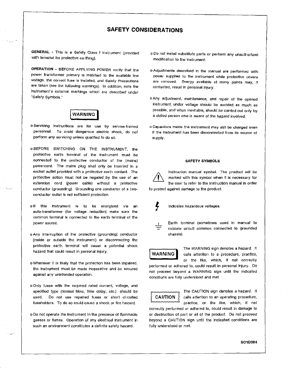
SAFETY CONSIDERATIONS
GENERAL • This is a
with terminal for protective earthing).
OPERATION
power
voltage,
are taken (see the following warnings). In addition, note the
instrument's
"Safety
o
Ser
....
personnel. To avoid dangerous electric shock, do not
perform any servicing unless qualified to do so.
~
BEFORE
transformer
the
correct
external markings which are described
Symbols."
lclng
Instructions
Safety
Class I Instrument (provided
APPLYING
primary is matched to the available line
fuse
Is Installed,
I
WARNING
are
for
POWER
and
I
use
verify
Safety
by
servlce-trarned
that
the
Precautions
under
o BEFORE SWITCHING ON THE INSTRUMENT, the
protective earth terminal of the Instrument
connected to the protective conductor of the (mains)
powercord. The mains plug shall only be inserted In a
socket outlet provided
protective action must not be negated by the use of an
extension
conductor
conductor
cord
(grounding). Grounding one
outlet Is not sufficient protection.
with
a protective earth contact. The
(power cable) without a protecttve
conductor
must
of a
be
two-
o Do not Install substitute
modification to the Instrument.
o Adjustments described In the manual are
power supplied to the
are removed. Energy available at
contacted, result In personal
a Any adjustment, maintenance, and repair of the opened
instrument
possible, and when Inevitable, should be carried
a skilled person
o Capacitors Inside the
If the Instrument has been disconnected
under
who
partsorperform
Instrument
Injury
voltage should be avoided as
Is aware of the
Instrument
may
while
.
hazard
many
still be
from
any
unauthorIzed
performed
protective
points
Involved.
charged
Its
much
out
source
with
covers
may, If
only by
even
supply.
SAFETY
;';\
Instruction manual symbol.
ill
to protect against damage to the
marked
the user to refer to the
with
SYMBOLS
The
product
this symbol when It Is necessary
Instruction
product.
manual in
wllf be
order
as
of
for
this
a If
auto-transformer
common terminal Is connected to the
power source.
Any
o
(Inside or outside
protective
hazard
o Whenever it Is likely
the Instrument
against any unintended operation.
o Only fuses With the required rated current, voltage, and
specified
used. Do not use repaired fuses or
fuseholders. To do so could cause a
o Do
gasses or fumes. Operation of any electrical instrument In
such
Instrument is to be energized via an
(for voltage reduction) make
earth
interruption of the protective (grounding)
the
Instrument) or dlsconnecttng the
earth
terminal will cause a potential
that
could result in personal Injury.
that
the protection has been impaired,
must
be made Inoperative and be secured
type
(normal blow, time delay, etc.) should be
shock
not
operate the
an environment constitutes a definite safety
instrumentinthe
presence of flammable
sure
terminal of the
conductor
shock
short
clrculted
or fire hazard.
hazard.
the
Indicates
-L
Earth terminal (sometimes used in manual to
indicate
chassis).
I
WARNING
performed or adhered to, could result In personal Injury. Do
not proceed beyond a
conditions are
~
~
correctly performed or adhered to, could result in
or destruction of
beyond a CAUTION sign until the Indicated conditlons are
fully understood or met.
hazardous
circuit
The WARNING sign denotes a
voltages.
common connected to
grounded
hazard.
I calls attenlion to a procedure, practice,
or the like, which, if not
WARNING
fully understood and met.
The CAUTION sign
calls attention to an operating procedure,
practice, or the like, which, if
part
or all of the
sign until the Indicated
denotesahazard.
product.
Do
correctly
damage
not
proceed
not
S010984
It
It
to
Page 7
HP 54201A/D-Table of Contents
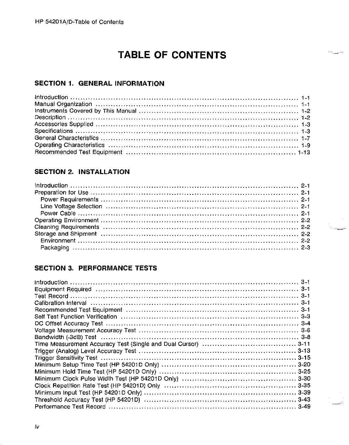
TABLE OF CONTENTS
SECTION 1. GENERAL INFORMATION
Introduction 1-1
Manual Organization 1-1
Instruments Covered by This Manual 1-2
Description '" , " .. , 1-2
Accessories Supplied 1-3
Specifications , " ,
General Characteristics 1-7
Operating Characteristics 1-9
Recommended Test Equipment 1-13
SECTION 2. INSTALLATION
Introduction , '" ., 2-1
Preparation for Use , , 2-1
Power Requirements 2-1
Line Voltage Selection 2-1
Power Cable ,.. " .. ,
Operating Environment 2-2
Cieaning Requirements 2-2 .
Storage and Shipment 2-2
Environment , ,. '" 2-2
Packaging 2-3
1-3
2-1
~~
SECTION 3. PERFORMANCE TESTS
Introduction , , , 3-1
Equipment Required 3-1
Test Record , , , 3-1
Calibration Interval
Recommended Test Equipment 3-1
Self Test Function Verification 3-3
DC Offset Accuracy Test 3-4
Voltage Measurement Accuracy Test
Bandwidth (-3dB) Test 3-8
Time Measurement Accuracy Test (Single and Dual Cursor) 3-11
Trigger (Analog) Level Accuracy Test 3-13
Trigger Sensitivity Test 3-15
Minimum Setup Time Test (HP 54201D Only) 3-20
Minimum Hold Time Test (HP 54201D Only) 3-25
Minimum Ciock Pulse Width Test (HP 54201D Only) 3-30
Clock Repetition Rate Test (HP 54201D) Only 3-35
Minimum Input Test (HP 54201D Only) 3-39
Threshold Accuracy Test (HP 54201D)
Performance Test Record 3-49
iv
3-1
3-6
3-43
Page 8
HP 54201
AjD
- Table of Contents
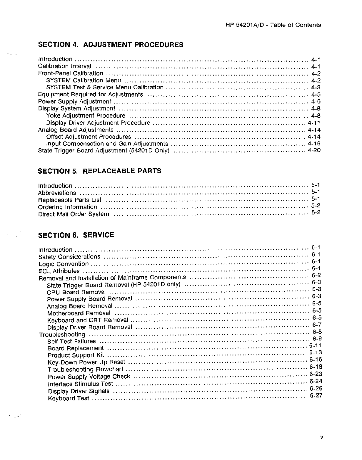
SECTION 4. ADJUSTMENT PROCEDURES
Introduction " ,.. , '" , ,.. , 4-1
Calibration Interval 4-1
Front-Panel Calibration 4-2
SYSTEM Calibration Menu 4-2
SYSTEM Test
Equipment Required for Adjustments 4-5
Power Supply Adjustment , , 4-6
Display System Adjustment 4-8
Yoke Adjustment Procedure 4-8
Display Driver
Analog Board Adjustments 4-14
Offset Adjustment Procedures 4-14
Input Compensation and Gain Adjustments 4-16
State Trigger Board Adjustment (54201D Only) 4-20
& Service Menu Calibration , , , 4-3
Adjustment
Procedure 4-11
SECTION 5. REPLACEABLE PARTS
Introduction " ., , '" , , '" '" .. , 5-1
Abbreviations 5-1
Replaceable Parts List 5-1
Ordering Information 5-2
Direct Maii Order
System
5-2
SECTION 6. SERVICE
Introduction , , , , , , , 6-1
Safety Considerations 6-1
logic
ECl
Removal and Installation of Mainframe Components 6-2
Convention , '" ., , , 6-1
Attributes ·· .. ·· · ·· .. · · 6-1
State Trigger Board Removal (HP 54201D only) 6-3
CPU Board Removal 6-3
Power Supply Board Removal ·· ..
Analog Board Removal , 6-5
Motherboard Removal 6-5
Keyboard and CRT Removal , , , , ,.. , , '" 6-5
Display Driver Board Removal 6-7
Troubleshooting 6-8
Self Test Failures 6-9
Board Replacement · ·
Product Support Kit 6-13
Key-Down Power-Up Reset 6-16
Troubleshooting Flowchart 6-18
Power Supply Voltage Check 6-23
Interface Stimulus Test , '" , , 6-24
Display Driver Signals 6-26
Keyboard Test 6-27
····················
···
6-3
6-11
v
Page 9
HP 54201A/D - Table of Contents
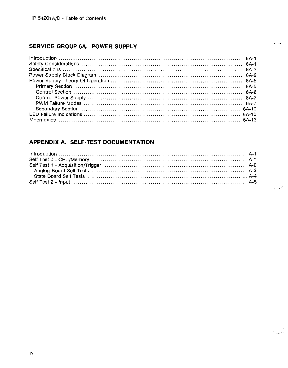
SERVICE GROUP
Introduction 6A-1
Safety Considerations 6A-1
Specifications 6A-2
Power Supply Block Diagram 6A-2
Power Suppiy Theory Of Operation , , " ., .. .. 6A-5
Primary Section 6A-5
Control Section 6A-6
Control Power Supply 6A-?
PWM Failure Modes 6A-?
Secondary Section 6A-1O
LED Failure Indications 6A-1O
Mnemonics 6A-13
GA.
POWER SUPPLY
APPENDIX A. SELF-TEST DOCUMENTATION
Introduction A-1
Self Test 0 - CPU/Memory A-1
Self Test 1 - Acquisition/Trigger A-2
Analog Board Self Tests A-3
State Board Self Tests A-4
Self Test 2 - Input A-8
vi
Page 10
HP 54201A/D - General Information
SECTION 1
GENERAL INFORMATION
I
WARNING
Service information tnctuaeo in this manuai is for use of trained service
oersonnet. To avoid etectrtcet shock, do not perform any service
procedures in the manual or do any servicing to the HP 54201AID
unless you are qualified.
1-1. INTRODUCTION
This manual contains technical information concerning the installation, performance testing,
adjustments, and servicing of the HP 54201A and HP 54201D Digitizing Oscilloscopes. When
information concerns both models the system will be referred to as the HP
I
54201AfD.
1-2. MANUAL ORGANIZATION
Section 1, General Information. This section contains a description of this manual and the
Instrument. This section also gives the specifications, general characteristics, operating
characteristics and recommended test equipment for the HP
Section 2, Installation. This section explains how to prepare the HP 54201AID for use.
Section 3, Performance Tests. This section describes both the self test capabilities of the HP
54201AID as well as the procedures for the full Performance Test.
Section 4, Adjustments. The HP 54201
performance after some major repairs have been made. This section provides the necessary
adjustment procedures.
Section 5, Replaceable Parts. This section contains ordering information and a list of all
replaceable parts in the HP
Section 6, Service. This section contains disassembly and assembly procedures and
documentation and procedures for isolation and replacement of faulty circuit boards.
Service Group 6A, Power Supply. This section contains block diagrams and component level
theory, troubleshooting and schematic information necessary to service the HP 54201
supply.
54201A/D system.
AID requires several adjustments to restore specified
54201A/D.
AID power
Appendix A, Self Test Documentation. This section contains an overview of how the HP
self tests werk and what portions of the HP 54201AID circuitry they check.
54201A/D
1-1
Page 11
HP 54201AID - General Information
1-3. INSTRUMENTS COVERED BY THIS MANUAL
Attached to the instrument is a serial number sticker. The serial number is in the form
OOOOAOOOOO.
five digits are the suffix. The prefix is the same for all identical HP 54201A or HP 54201D
instruments; the prefix only changes when a change is made to the instrument. The suffix,
however, is assigned sequentially and is different for each instrument. The contents of this manual
applies to instruments with serial number prefix(es) listed under SERIAL NUMBERS on the title
page. The serial number is also displayed on the HP 54201
Peripherals menu is selected.
An instrument manufactured after the printing of this manual may have a serial number prefix not
listed on the title page. This unlisted serial prefix indicates the instrument is different from those
described in this manual. The manual for this newer instrument is accompanied by a
Manual Changes supplement. The supplement contains "change information" that explains
adapt the manual to the newer instrument.
In addition to change information, the supplement may contain information for correcting errors in
the manual. To keep this manual as current and accurate as possible, Hewlett-Packard
recommends that you periodically request the latest Manual Changes supplement. The
supplement is identified by the manual print date and part number, both of which appear on the
manual title page. Complimentary copies of this supplement are available on request.
It is in two parts; the first four digits and the ietter are the serial prefix and the last
AID screen when the SYSTEM
yellow
how
to
Shown on the title page is a microfiche part number. This number can be used to order 4
microfilm transparencies of this manual. Each microfiche contains up to
manual pages.
96 photoduplicates of the
X 6 inch
1-4. DESCRIPTION
The HP 54201A and HP 54201D Digitizing Oscilloscopes are dedicated, two-channel,
simultaneous, waveform acquiring digital storage oscilloscopes with full HP-IB programmability,
digitized waveform data output, and resident parametric waveform measurements.
The HP
and a single-shot digital storage bandwidth of 50 MHz (200 rneqesamptes/secono) With Infinite
store time and waveform data output. It also provides parametric information about the analog
characteristics of waveforms.
The HP 54201D has all the features of the HP 54201A with the addition of parallel and serial logic
trigger qualification capabilities. The HP 54201D includes 3 pods, each containing
bit
54201A/D is a generai purpose digitizing oscilioscope with 300 MHz repetitive
+ clock organization.
?andV1dd.th
8 bit + 1 parity
1-2
Page 12
HP 54201AjD - General Information
The key features of the HP 54201AjD Digitizing Oscilloscopes are:
• 300 MHz repetitive bandwidth with ±200 ps lime-interval accuracy.
• 200 megasamplesjsecond sample rate, 50 MHz single-shot bandwidth using post capture
data interpolation.
• Capture two channels simultaneously.
•
Holdoff-by-events
• Pre-trigger viewing.
• All front panel controllabie parameters can be programmed via HP-IB.
• Continuously updated automatic waveform parameter measurements with user-defined
thresholds.
• Waveform math: Ch1+Ch2 and Ch1-Ch2.
to trigger acquisition alter a specified number of events.
• Set up aids such as automatic waverform scaling,
front-panel setups.
• One button hardcopy to HP-IB printers and plotters.
• Digital logic trigger qualification (HP 54201D only).
ECl/TTl
1-5. ACCESSORIES SUPPLIED
The following accessories are supplied with the instruments:
HP 54201AjD: Two HP 10017A 10:1 divider probes.
One BNC to probe tip adapter.
One 2.3 meter (7.5
One Operating and Programming Manual.
One Service Manual.
HP 542010 (only): Three HP 10271A 10-bit State Data Probes.
It) power cord.
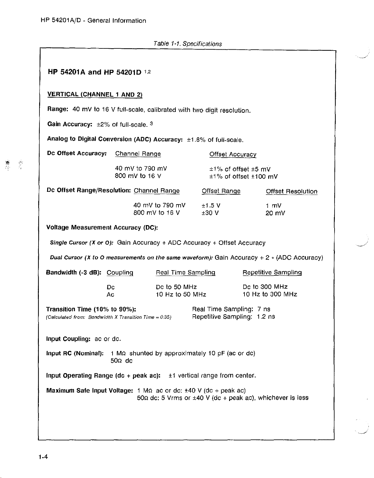
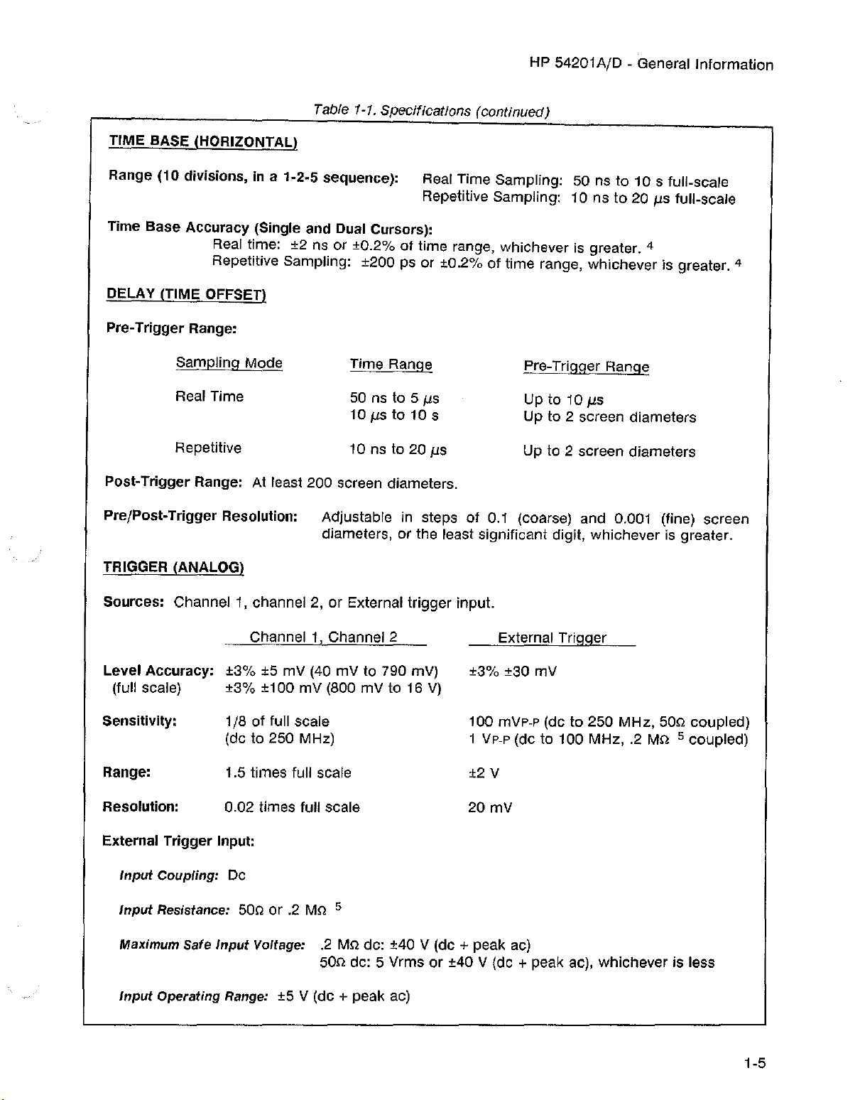
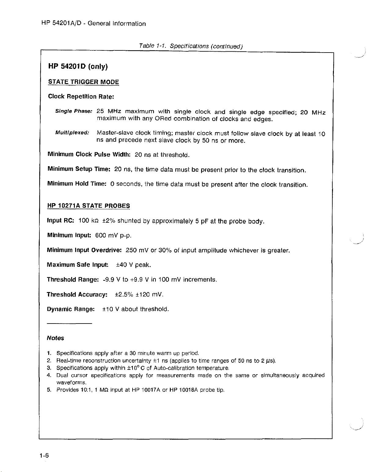
1-6. SPECIFICATIONS
preset levels, and save/recall of
Instrument specifications are listed in table 1-1. These specifications are the performance
standards or limits against which the instrument is tested.
1-3
Page 13
HP 54201A/D - General Information
HP
54201Aand
HP 542010 1,2
VERTICAL (CHANNEL 1 AND 2)
Table 1-1. Specifications
Range: 40 mV to 16 V full-scale, calibrated with
Gain
Analog
Dc
Offset
Accuracy:
to Digital Conversion (ADC) Accuracy: ±1.6% of full-scale.
Accuracy:
±2%
of full-scale. 3
Channel Range
40 mV to 790 mV
800mVt016V
Dc
Offset
Voltage
Single
Dual
Bandwidth (-3 dB):
Range/Resolution: Channel Range
40 mV to 790
800mVt016V
Measurement
Cursor(Xor
Cursor(Xto
Accuracy
0):
Gain
0 measurements on
(DC):
Accuracy
Coupling
Dc
Ac
mV
+ ADC Accuracy + Offset
the
same
Real Time Sampling
Dc to 50
10 Hz to 50 MHz
two
digit resolution.
Offset Range
±1.5 V
±30 V
waveform):
MHz
Offset
±1%ofoffset
±1% of offset ±100
Accuracy
±5 mv
mV
Offset Resolution
1 mV
mV
20
Accuracy
Gain Accuracy + 2 * (ADC Accuracy)
300
Sampling
MHz
300
MHz
Repetitive
Dc to
10 Hz to
Transition Time
(Calculated from: Bandwidth X Transition Time = 0.35)
(10%to90%):
Real Time Sampling: 7 ns
Repetitive Sampling: 1.2 ns
Input Coupling: ac or de.
Input RC (Nominal): 1 MQ shunted by approximately 10 pF (ae or de)
50Q de
Input Operating Range (dc
Maximum Safe Input Voltage: 1 MQ ae or de: ±40 V (de
+
peak
ae): ±1 vertical range
50Q de: 5 Vrms or ±40
from
+ peak ae)
V (de + peak ac),
1-4
center.
whichever
is less
Page 14
HP 54201AID - General Information
Table 1-1. Specifications (continued)
TIME BASE (HORIZONTAL)
Range (10 divisions, in a 1-2-5 sequence): Real Time Sampling: 50 ns to 10 s full-scale
Repetitive Sampling: 10 ns to 20
/.Is
full-scale
Time Base Accuracy (Single and Dual Cursors):
Real time: ±2 ns or ±0.2% of time range, whichever is greater. 4
Repetitive Sampling: ±200 ps or ±0.2% of time range, whichever is greater. 4
DELAY (TIME OFFSET)
Pre-Trigger Range:
Sampling Mode
Real Time
Repetitive
Time Range
50 ns to 5
10
/.Is
to 10 s
10 ns to 20
/.IS
/.IS
Pre-Trigger Range
Up to 10
/.IS
Up to 2 screen diameters
Up to 2 screen diameters
Post-Trigger Range: At least 200 screen diameters.
Pre/Post.Trigger Resolution: Adjustable in steps of 0.1 (coarse) and 0.001 (fine)
diameters, or the least significant digit, whichever is greater.
TRIGGER (ANALOG)
Sources: Channel 1, channel 2,orExternal trigger input.
Level Accuracy:
Channel 1, Channel 2
±3%
±5 mV (40 mV to 790 mv)
External Trigger
±3% ±30 mV
(full scale) ±3% ±100 mV (800 mV to 16 V)
Sensitivity:
Range:
1/8 of full scale
(de to 250 MHz)
1.5 times full scale
100 mVp-p (de to 250
MHz,
500 coupled)
1 Vp-p (de to 100 MHz, .2 MO 5 coupled)
±2 V
screen
Resolution:
0.02 times full scale
External Trigger Input:
Input
Coupling: Dc
Input
Resistance: 500 or .2 Mo 5
Maximum Safe
Input
Operating Range: ±5 V (de + peak ae)
Input
20 mV
Voltage: .2 MQde: ±40 V (de + peak ac)
50Q de: 5 Vrms or ±40 V (de + peak ac), whichever is less
1-5
Page 15
HP 54201
AID
- General Information
HP 542010 (only)
STATE TRIGGER MODE
Table 1-1. Specifications (continued)
Clock
Repetition Rate:
Single
Multiplexed:
Phase:
25 MHz
maximum
Master-slave
maximum
with
clock
with single
any ORed combination of
timing; master
ns and precede next slave
clock
Minimum Clock Pulse Width: 20 ns at threshold.
Minimum Setup Time: 20
ns, the
Minimum Hold Time: 0 seconds, the
time
data
time
must
data
HP 10271A STATE PROBES
Input RC: 100
Minimum Input: 600 mV
Minimum Input Overdrive:
Maximum
kQ
±2%
Sale
Input: ±40 V peak.
shunted by approximately 5 pF at the
p-p,
250
mV or 30% of
input
clock
and single edge specified; 20
clock
clocks
must
and edges.
follow
slave
by 50 ns or more.
be present prior to the
must
be present after the
probe
body.
amplitude whichever is greater.
clock
clock
clock
MHz
by at least 10
transition.
transition.
Threshold Range:
-9.9 V to +9.9 V in 100 mV increments.
Threshold Accuracy: ±2.5% ±120 mY.
Dynamic Range: ±10 V
about
threshold.
Notes
1. Specifications apply after a 30
2.
Real-time
3. Specifications apply within ±10°C of Auto-calibration temperature.
4. Duai cursor specifications apply for
waveforms.
5.
Provides
reconstruction uncertainty±1ns
10:1,1 MQ inputat HP
minute
10017A
warm up
period.
(applies
measurements
or HP
10018A
to time
made
probetip.
1-6
ranges
on the
of 50 ns to 2I1s).
same
or simultaneously acquired
Page 16
HP 54201A/D - General Information
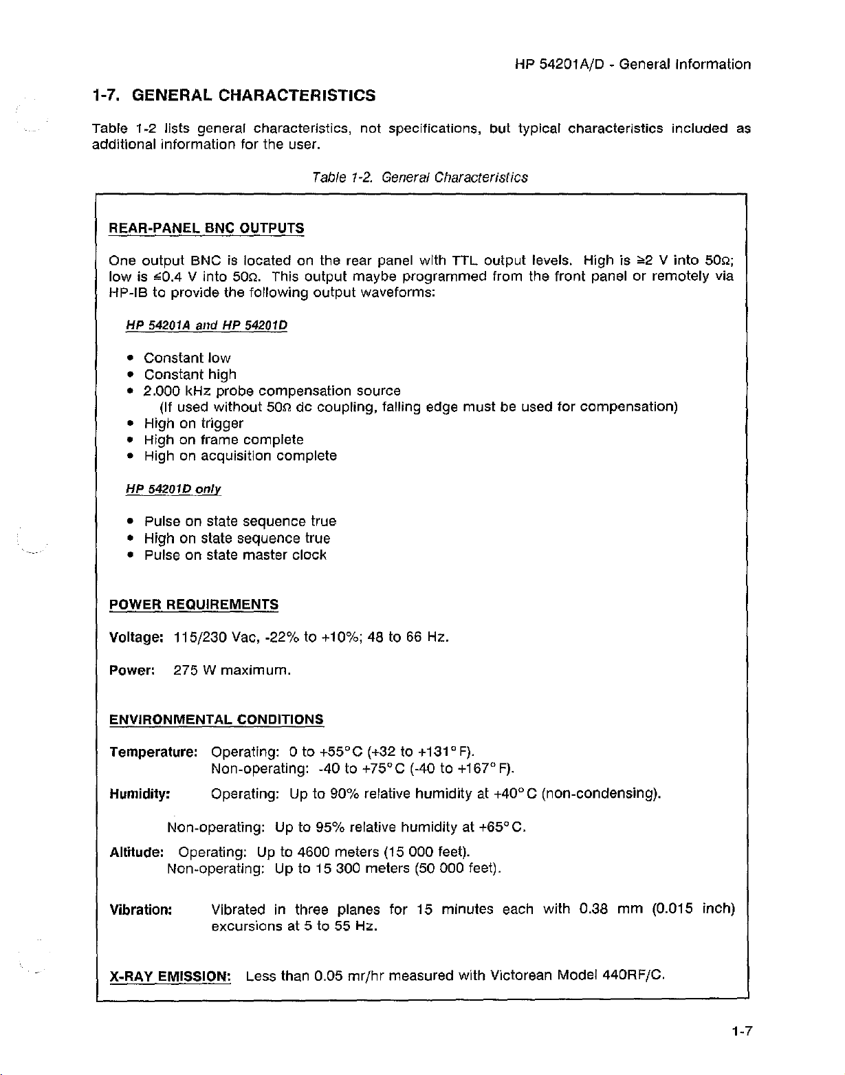
1-7. GENERAL CHARACTERISTICS
Table 1-2 lists general characteristics, not specifications, but typical characteristics included as
additional information for the user.
Table 1-2. General Characteristics
REAR-PANEL BNC OUTPUTS
One output BNC is located on the rear panel with TTL output levels. High is
low is
~0.4
V into
50Q.
This output maybe programmed from the front panel or remotely via
HP-IB to provide the following output waveforms:
HP 54201A
• Constant
and
HP 54201D
low
• Constant high
• 2.000 kHz probe compensation source
(If used without
50Qde coupling, falling edge must be used for compensation)
• High on trigger
• High on frame complete
• High on acquisition complete
HP 54201D
only
• Pulse on state sequence true
• High on state sequence true
• Pulse on state master clock
POWER REQUIREMENTS
Voltage: 115/230
Vac, -22% to +10%; 48 to 66 Hz.
,,2 V
into
50Q;
Power: 275
W maximum.
ENVIRONMENTAL CONDITIONS
Temperature: Operating: 0 to
+55°C
(+32 to +131° F).
Non-operating: -40 to +75°C (-40 to +167° F).
Humidity: Operating: Up to 90% relative humidity at +40
Non-operating: Up to 95% relative humidity at +650C.
Altitude: Operating: Up to 4600 meters (15 000 feet).
Non-operating: Up to 15 300 meters (50 000 feet).
Vibration:
Vibrated in three planes for 15 minutes each with 0.38
excursions at 5 to 55 Hz.
mr/hr
X-RAY EMISSION: Less than 0.05
measured with Victorean Model 440RF/C.
0
C (non-condensing).
mm
(0.015 inch)
1-7
Page 17
HP 54201AID - General Information
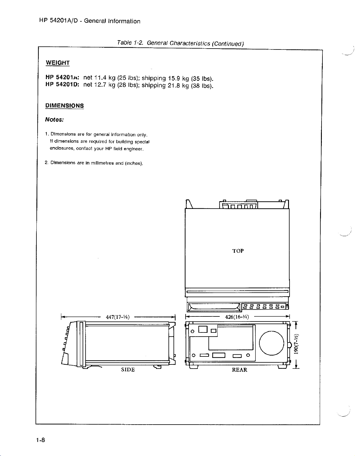
Table 1-2. General Characteristics (Continued)
WEIGHT
HP
54201A: net 11.4 kg (25 Ibs); shipping 15.9 kg (35 Ibs).
HP 542010: net 12.7 kg (28 Ibs); shipping 21.8 kg (38 Ibs).
DIMENSIONS
Notes:
1. Dimensions are for general information only.
If dimensions are required for building special
enclosures, contact your HP field engineer.
2. Dimensions are In mltltrnetres and (Inches).
I-
I
A
447(17-%)
SIDE
1 I
f\
1>-
I-
°
0
L...J
DOl
I
= c::::J
fF
TOP
?lr.CCl:lIccccl!
ClCCDCC
426(16-%) -I
=0
REAR
0
I
I
1
'--
1-8
Page 18
HP 54201A/D - General Information
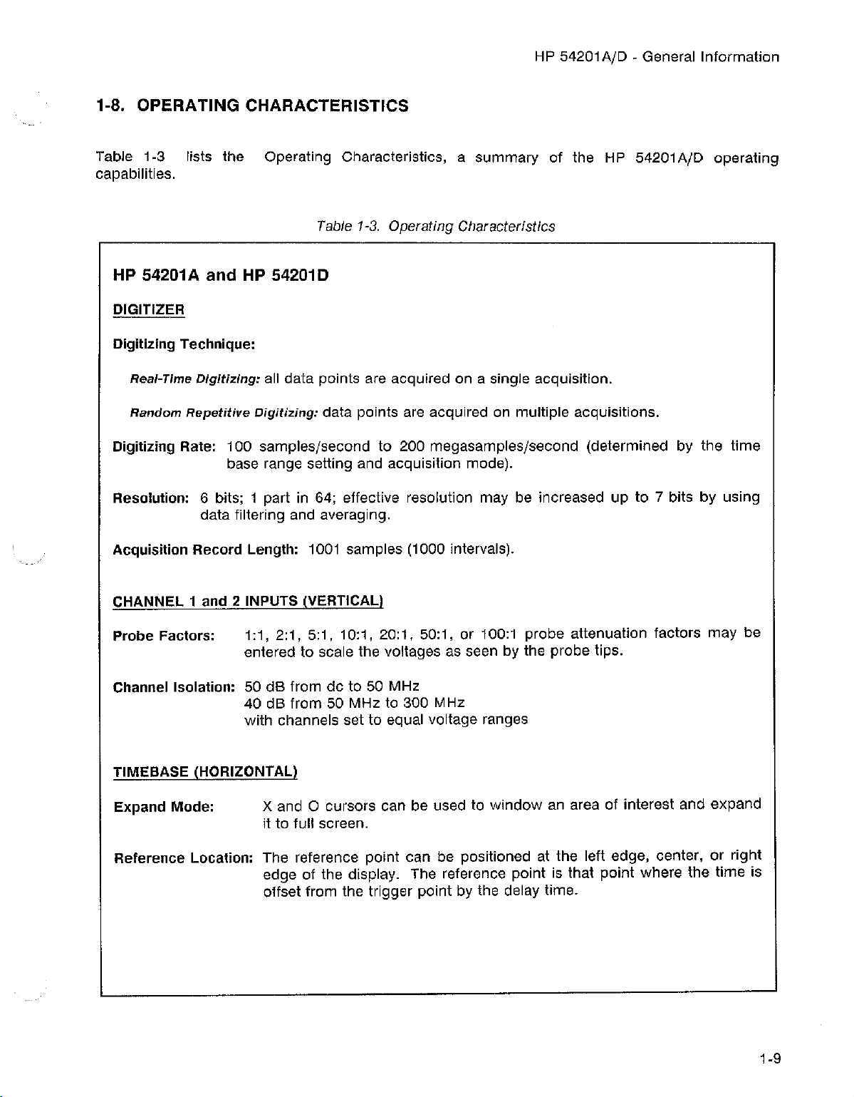
1-8. OPERATING CHARACTERISTICS
Table 1-3 lists the Operating Characteristics, a summary of the HP 54201AID operating
capabilities.
Table 1-3. Operating Characteristics
HP 54201A
and
HP 54201D
DIGITIZER
Digitizing Technique:
Real-Time
Random
Digitizing Rate: 100 samples/second to 200
Digitizing:
Repetitive
all data points are acquired on a single acquisition.
Digitizing:
data points are acquired on multiple acquisitions.
rneqasamples/second (determined by the time
base range setting and acquisition mode).
Resolution: 6 bits; 1 part in 64; effective resolution may be increased up to 7 bits by using
data filtering and averaging.
Acquisition Record Length: 1001 samples (1000 intervals).
CHANNEL 1 and 2 INPUTS (VERTICAL)
Probe Factors:
1:1,2:1,5:1,10:1,20:1,50:1,
or 100:1 probe attenuation factors
may
be
entered to scale the voltages as seen by the probe tips.
Channel Isolation: 50 dB from de to 50 MHz
40 dB from 50 MHz to 300 MHz
with channels set to equal voltage ranges
TIMEBASE (HORIZONTAL)
Expand Mode: X and
0 cursors can be used to
window
an area of interest and expand
it to full screen.
Reference Location: The reference point can be positioned at the left edge, center, or right
edge of the display. The reference point is that point where the time is
offset from the trigger point by the delay time.
1-9
Page 19
HP 54201A/D - General Information
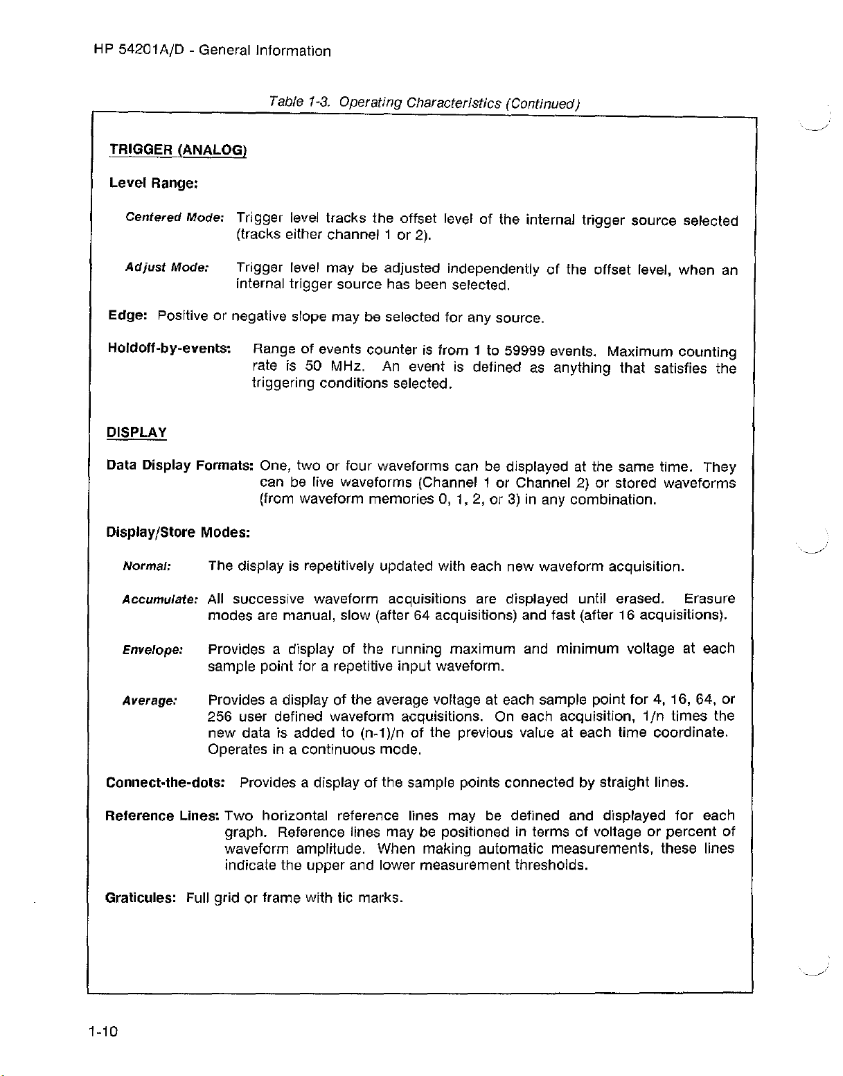
Table 1-3. Operating Characteristics (Continued)
TRIGGER (ANALOG)
Level Range:
Centered
Mode: Trigger level tracks the offset level of the internal trigger source selected
(tracks either channel 1 or 2).
Adjust
Mode:
Trigger level may be adjusted independently of the offset level, when an
internal trigger source has been selected.
Edge: Positive or negative slope may be selected for any source.
Holdoff-by-events: Range of events counter is from 1 to 59999 events. Maximum counting
rate is 50 MHz. An event is defined as anything that satisfies the
triggering conditions selected.
DISPLAY
Data Display Formats: One, two or four waveforms can be displayed at the same time. They
can be live waveforms (Channel 1 or Channel 2) or stored waveforms
(from waveform memories
O.
1,2,
or 3) in any combination.
Display/Store Modes:
Normal:
Accumulate:
The display is repetitively updated with each new waveform acquisition.
All successive waveform acqulsitlcns are displayed until erased. Erasure
modes are manual. slow (after 64 acquisitions) and fast (after 16 acquisitions).
Envelope: Provides a display of fhe running maximum and minimum voltage at each
sample point for a repetitive input waveform.
Average: Provides a display of the average voltage at each sample point for 4, 16, 64, or
256 user defined waveform acquisitions. On each acquisition, 1/n times the
new data is added to (n-t)/n of the previous value at each time coordinate.
Operates in a continuous mode.
connect-the-dots. Provides a display of the sample points connected by straight lines.
Reference Lines: Two horizontal reference lines may be defined and displayed for each
graph. Reference lines may be positioned in terms of voltage or percent of
waveform amplitude. When making automatic measurements, these lines
indicate the upper and lower measurement thresholds.
Gralicules: Full grid or frame with lie marks.
1-10
Page 20
HP 54201
AID
- General Information
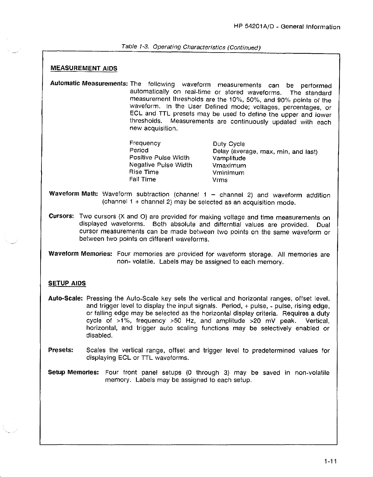
Table 1-3.
MEASUREMENT AIDS
Automatic Measurements:
The following waveform measurements can be performed
Operating
Characteristics
(Continued)
automatically on real-time or stored waveforms. The standard
measurement thresholds are the 10%, 50%, and 90% points of the
waveform. In the User Defined mode; voltages, percentages, or
ECl
and
TTL
presets may be used to define the upper and lower
thresholds. Measurements are continuously updated with each
new acquisition.
Frequency
Period
Positive Pulse Width
Negative Pulse Width
Rise Time
Fall Time
Waveform Math: Waveform subtraction (channel 1 - channel 2) and waveform addition
(channel 1
Cursors: Two cursors (X and
+ channel 2) may be selected as an acquisition mode.
0)
are provided for making voltage and time measurements on
Duty Cycle
Delay (average, max, min, and last)
Vamplitude
Vmaximum
Vminimum
Vrms
displayed waveforms. Both absolute and differntial vaiues are provided. Dual
cursor measurements can be made between two points on the same waveform or
between two points on different waveforms.
Waveform Memories: Four memories are provided for waveform storage. All memories are
SETUP AIDS
Auto-Scale:
non- volatile.
Pressing the Auto-Scale key sets the vertical and horizontal ranges, offset level,
and trigger level to display the input signals. Period,
labels
may be assigned to each memory.
+ pulse, - pulse, rising edge,
or falling edge may be selected as the horizontai display criteria. Requires a duty
cycle of >1%, frequency >50 Hz, and amplitude >20 mV peak. Vertical,
horizontal, and trigger auto scaling functions may be selectively enabled or
disabled.
Presets: Scales the vertical range, offset and trigger level to predetermined values for
displaying
Setup Memories: Four front panel setups
ECl
or TTL waveforms.
(O
through 3) may be saved in non-volatile
memory. Labels may be assigned to each setup.
1-11
Page 21
HP 54201AjD - General Information
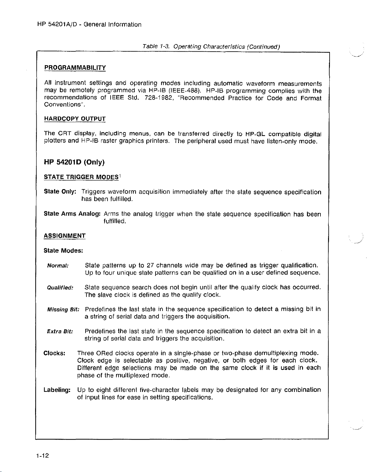
Table 1-3. Operating Characteristics (Continued)
PROGRAMMABILITY
All instrument settings and operating modes including automatic waveform measurements
may be remotely programmed via HP-IB (IEEE-488). HP-IB programming complies with the
recommendations of IEEE Std. 728-1982, "Recommended Practice for Code and Format
Conventions".
HARDCOPY
OUTPUT
The CRT display, including menus, can be transferred directly to HP-GL compatible digital
plotters and HP-IB raster graphics printers. The peripheral used must have listen-only mode.
HP
542010
STATE TRIGGER
(Only)
MODES1
Slale Only: Triggers waveform acquisition immediately after the state sequence specification
has been fulfilled.
State Arms Analog: Arms the analog trigger when the state sequence specification has been
fulfilled.
ASSIGNMENT
Stale Modes:
Normal:
Qualified:
State patterns up to 27 channels wide may be defined as trigger qualification.
Up to four unique state patterns
can
be qualified on in a user defined sequence.
State sequence search does not begin until after the qualify clock has occurred.
The slave clock is defined as the qualify clock.
Bil:
Missing
Predefines the last state in the sequence specification to detect a missing bit in
a string of serial data and triggers the acquisition.
Extra
Bit:
Predefines the last state in the sequence specification to detect an extra bit in a
string of serial data and triggers the acquisition.
Clocks: Three ORed clocks operate in a single-phase or two-phase demultiplexing mode.
Clock edge is selectable as positive, negative, or both edges for each clock.
Different edge selections may be made on the same clock if it is used in each
phase of the multiplexed mode.
Labeling: Up to eight different five-character labels may be designated for any combination
of input lines for ease in setting specifications.
1-12
Page 22
HP 54201A/D - General Information
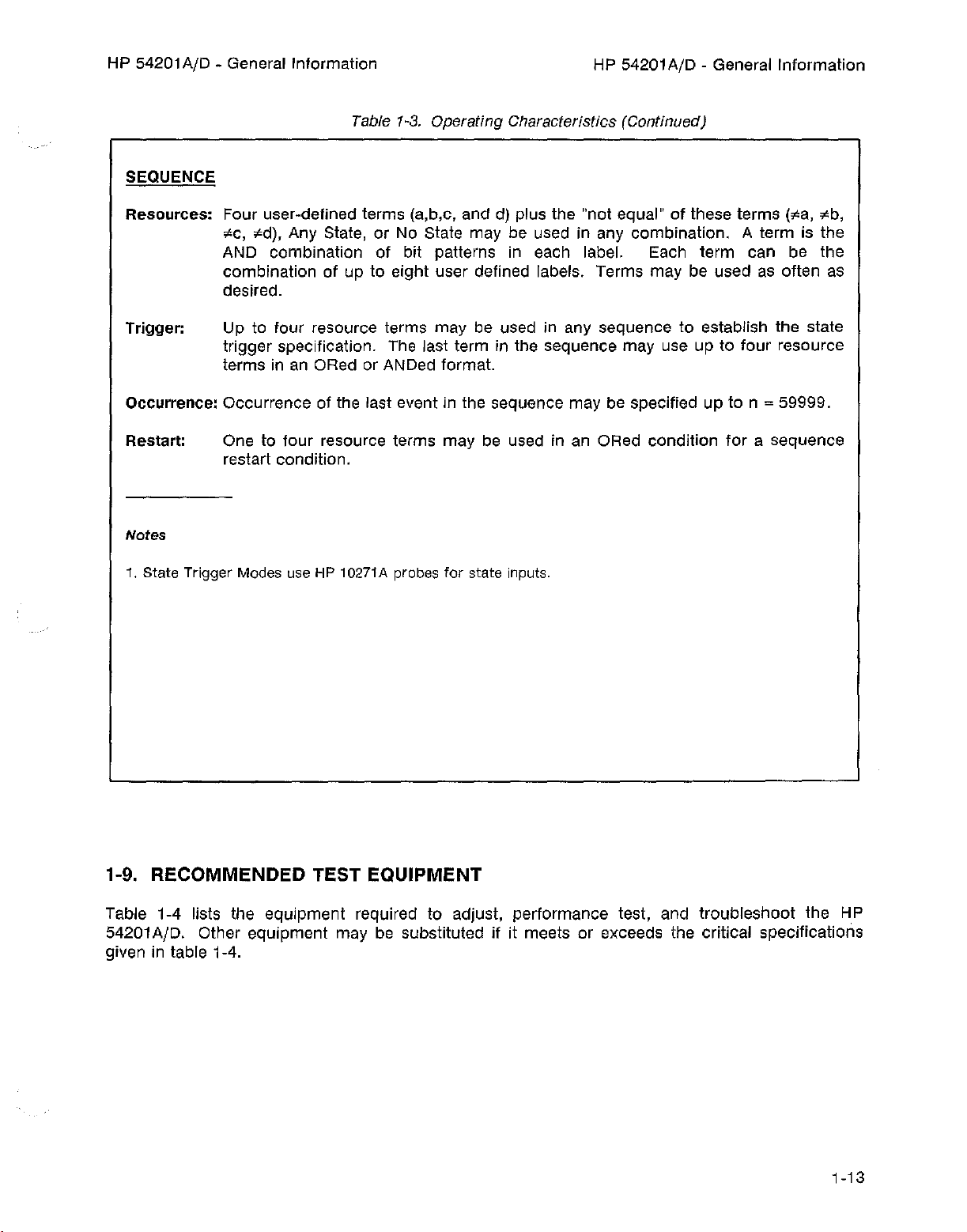
Table 1-3. Operating Ctierecteristtcs (Continued)
SEQUENCE
HP 54201A/D - General Information
Resources: Four user-defined terms (a.b,c, and d) plus the "not equal" of these terms
"c,
"d), Any State, or No State may be used in any combination. A term is the
("a,
seb,
AND combination of bit patterns in each label. Each term can be the
combination of up to eight user defined labels. Terms may be used as often as
desired.
Trigger: Up to four resource terms may be used in any sequence to establish the state
trigger specification. The last term in the sequence may use up to four resource
terms in an ORed or ANDed format.
Occurrence: Occurrence of the last event in the sequence may be specified up to n
Restart:
One to four resource terms may be used in an ORed condition for a sequence
= 59999.
restart condition.
Nofes
1. State Trigger
Modes
useHP 10271A
probes
for state
inputs.
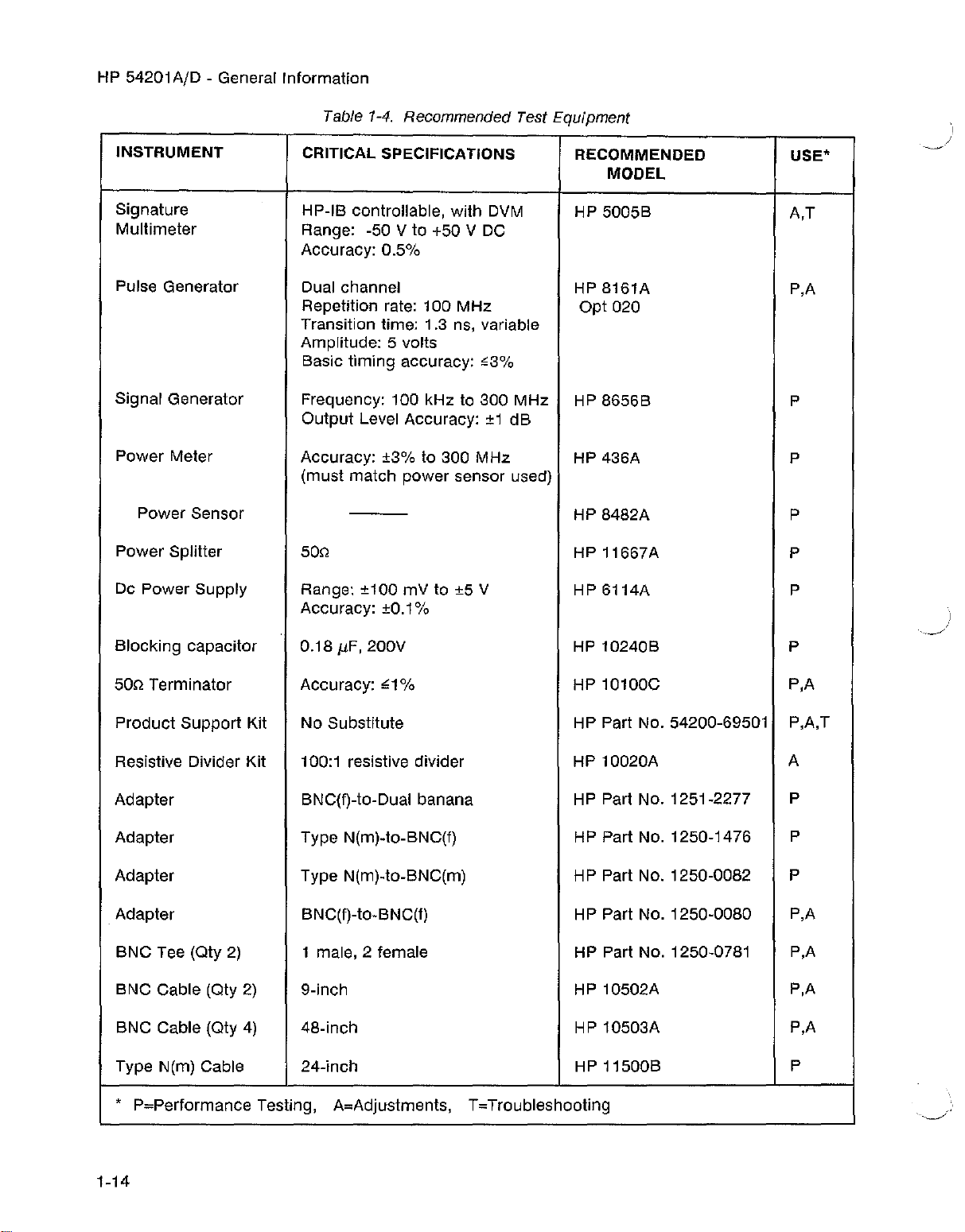
1-9. RECOMMENDED TEST EQUIPMENT
Table 1-4 lists the equipment required to adjust, performance test, and troubleshoot the HP
54201A/D. Other equipment may be substituted if it meets or exceeds the critical specifications
given in table 1-4.
1-13
Page 23
HP 54201 AID - General Information
INSTRUMENT
Signature
Multimeter
Pulse Generator
Signal Generator
Power Meter
Power Sensor
Power Splitter
Table 1-4. Recommended Test Equipment
CRITICAL SPECIFICATIONS
HP-IB controllable, with DVM
Range: -50 V to +50 V DC
Accuracy: 0.5%
Dual channel
Repetition rate: 100
MHz
Transition time: 1.3 ns, variable
Amplitude: 5 volts
Basic timing accuracy:
~3%
Frequency: 100 kHz to 300 MHz
Output Level Accuracy: ±1 dB
Accuracy: ±3% to 300 MHz
(must match power sensor used)
50Q
RECOMMENDED
MODEL
HP 5005B
HP 8161A
opt
020
HP 8656B P
HP 436A
HP 8482A P
HP 11667A
"
~J
USE'
A,T
P,A
P
P
Dc Power Supply
Range: ±100 mV to ±5 V
HP 6114A
Accuracy: ±0.1%
Blocking capacitor 0.18
50Q Terminator Accuracy:
Product Support Kit
Resistive Divider Kit 100:1 resistive divider
Adapter BNC(f)-to-Dual banana
Adapter Type N(m)-to-BNC(f)
jJ.F,
200V
<:1
% HP 10100C P,A
HP 10240B P
No Substitute HP Part No. 54200-69501
HP 10020A
HP Part No. 1251-2277
HP Part No. 1250-1476
Adapter Type N(m)-to-BNC(m) HP Part No. 1250-0082
Adapter BNC(f)-tO-BNC(f) HP Part No. 1250-0080
BNC Tee (Qty 2)
BNC Cable (Qty 2)
BNC Cable (Qty 4)
1 male, 2 female
9-inch
48-inch
HP Part No. 1250-0781
HP 10502A
HP 10503A
P
P,A,T
A
P
P
P
P,A
P,A
P,A
P,A
Type N(m) Cable 24-inch HP 11500B
, P=Performance Testing,
A=Adjustments, T=Troubleshooting
1-14
P
Page 24

HP 54201AID - Installation
SECTION 2
INSTALLATION
2-1. INTRODUCTION
This section contains the initial operation information for the HP 54201AfD. Included are power
and grounding requirements, operating environment requirements, cleaning methods and storage
and shipment requirements.
2-2. PREPARATION FOR USE
2-3. Power Requirements
The HP 54201A/D requires a power source of either 115 or 230 VAC -22% to +10%; single phase,
48 to 66 Hz; 275 watts maximum.
[:~~~~]
The instrument may be damagedifthe Line Voitage Select Switch
is not properly set to match the input voitage.
2-4. Line Voltage Selection
Before turning ON the instrument verify that the Line Voltage Select Switch on the rear panel
matches the input line voltage. The 6 Amp fuse installed satisfies both voltage settings of 115 and
230 VAC.
2-5. Power Cable
This instrument is equipped with a three-wire power cable. When connected to an appropriate AC
power outlet, this cable grounds the instrument cabinet. The type of power cable plug shipped
with the instrument depends on the country of destination. See figure 2-1 for option numbers of
power cables and plug configurations available. Part numbers for each cable option are listed in
the replaceable parts section of this manual.
CPT[OO 992
CAEl£_ toP
~
OPTION
9131
CAEIl..E:i1
Hl'
e12B~16g2
812B-e;96
C(NTltOIT
""""'"
250Y OPERArICN 220\1'
c:fITICH 912
CA9..E)t toP
fl./S1"RAILIA
foEW
Z<flA<D
8120-2951
~
CPTION 904
CAa..E:1t
~
(IF'ERATJCN
I-P 812B-BS98
OPTlQIl
CAELEII
913&
loP 9120-2'296
~
U.S.~
SWITZERLFI\lD
~EIV
CPERATtCN
OF'riOl
(ABL.£11 tF' 8120-1103
(PTIm
CAIl.,E:*
STD.
loP 812a--1521
u.s.~
~
iasv
9.
Cf'ERFITiON
.....IiED K[t«i[k)1
~
250V
OF'ERATIQII
~.
~
2S0V
<l"ERATlON
Figure 2-1. Power Cord Configurations
Q
250V
OF'£RAT
I
ON
2-1
Page 25

HP 54201A/D - Installation
2-6. OPERATING
ENVIRONMENT
The operating environment is noted in table 1-2. Note should be made of the non-condensing
humidity limitation. Condensation within the instrument can cause poor operation or malfunction.
Protection should be provided against internal condensation.
The HP 54201A/D will operate to all specifications, within the temperature and humidity range
given in table 1-2. However, reliability is enhanced by operating the instrument within the following
ranges.
Recommended Temperature: +20 to +35° C (+68 to +95° F)
Recommended Humidity: 20% to 80% non-condensing
High temperature/humidity combinations should be avoided.
2-7. CLEANING REQUIREMENTS
I
<:>
When cleaning the HP 54201A/D, CAUTION must be exercised on which cieaning agents are used.
USE MILD SOAP AND WATER. If a harsh soap or solvent is used, the water-base paint finish
WILL BE damaged.
BE CAREFUL when cleaning the keyboard. Water can damage the
keyboard circuitryifit seeps under the keys.
2-8. STORAGE AND SHIPMENT
2-9. Environment
The instrument may be stored or shipped in environments within the following limits:
Temperature: _40°C to
Humidity: Up to 90% at
Altitude:... Up to 15 300 metres (50 000 Feet)
,-75°C
65°C
The instrument should also be protected from temperature extremes which cause condensation
within the instrument. Condensation within the instrument may cause malfunction if the
instrument is operated under these conditions.
2-2
Page 26
2-10. Packaging
HP 54201A/D - Installation
2-11.
TAGGING FOR SERVICE. If the instrument is to be shipped to a Hewlett-Packard office for
service or repair, attach a tag showing owner (with address), complete instrument serial number,
and a description of the service required.
2·12.
ORIGINAL PACKAGING. If the original packing material is not available or is unserviceable,
material identical to those used in factory packaging are available through Hewlett-Packard offices.
If the instrument is to be shipped to a Hewlett-Packard office for servicing, attach a tag showing
owner (with address), model number, complete instrument serial number, and a description of the
service required. Mark the container FRAGILE to ensure careful handling. In any correspondence,
refer to the instrument by model number and serial number.
2-13.
OTHER PACKAGING. The following general instructions should be used for repacking with
commercially available materials.
a. Wrap instrument in heavy paper or plastic.
b. Use a strong shipping container. A double-wall carton made of 350 lb. test material is
adequate.
c. Use a layer of shock-absorbing material 70 to 100 mm (3 to 4 inch) thick around all sides of
the instrument to provide firm cushioning and prevent movement inside the container.
Protect control panel with cardboard.
d. Seal Shipping container securely.
e. Mark shipping container FRAGILE to ensure careful handling.
f. In any correspondence, refer to instrument by model number and full serial number.
2-3/(2-4 blank)
Page 27

.:»
,
Page 28
HP 54201AID - Performance Tests
SECTION 3
PERFORMANCE TESTS
3-1. INTRODUCTION
This section describes the HP 54201AfD Self Tests and Performance Test Procedures. The Self
Tests, resident in ROM, are a series of tests that confirm proper function of the mainframe
hardware and firmware. While the Self Tests provide the user with a confidence level of greater
than 90%, it does not verify the critical specifications given in table 1-1 of Section 1. The
Performance Tests test for complete instrument compliance to these critical specifications.
3-2. EQUIPMENT REQUIRED
The only equipment required for the Self Test is a standard
equipment required to perform the Performance Tests is listed in table 3-1. Other equipment may
be substituted if it meets or exceeds the critical specifications listed in table 3-1.
BNC
cable, 1 meter in iength. The
3-3. TEST RECORD
Results of performance tests may be tabulated on the Performance Test Record (table 3-2) at the
end of this section. The Test Record lists all of the tested specifications and their acceptable
limits. The results recorded at incoming inspection can be used for comparison in periodic
maintenance and troubleshooting and after repairs or adjustments.
Note
AI/ow instrument to warm up for at least 30 minutes
performance tests.
prior
to beginning
3-4. RECOMMENDED TEST EQUIPMENT
Table 3-1 lists the equipment required to performance test the HP 54201A/D. Other equipment
may be substituted if it meets or exceeds the critical specifications given in table 3-1.
3-1
Page 29
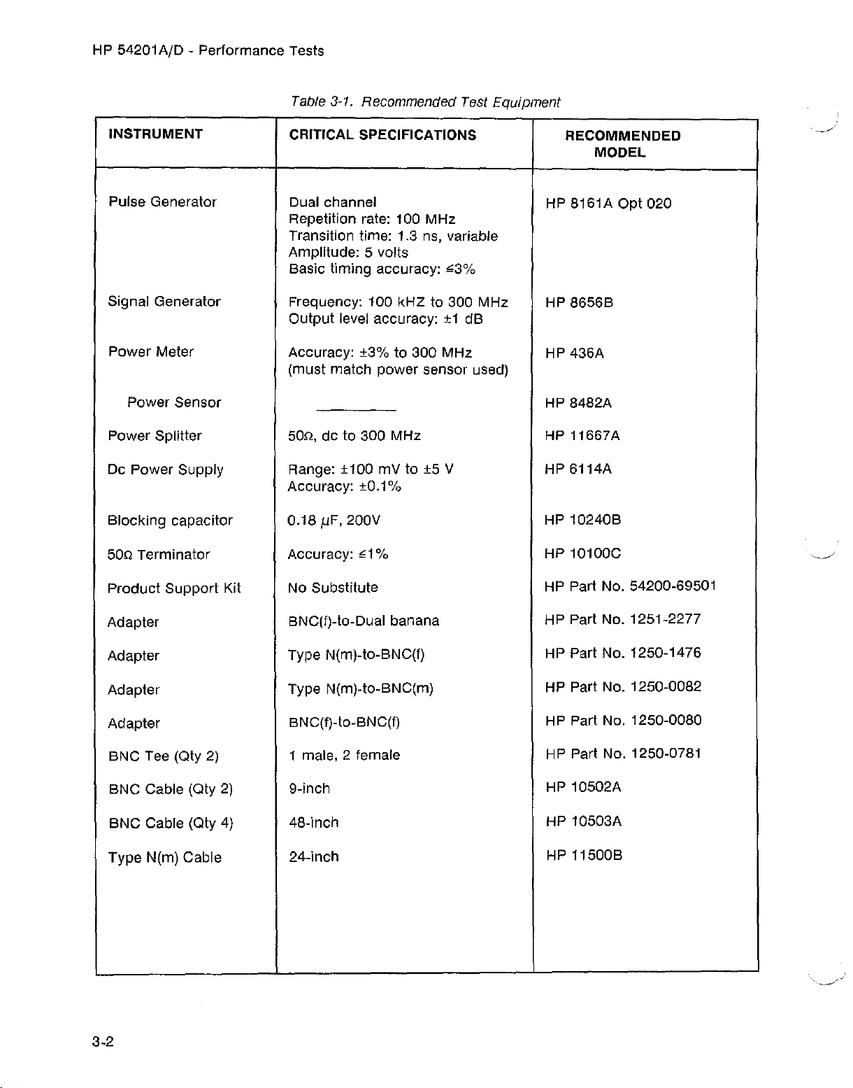
HP 54201A/D - Performance Tests
Table 3-1. Recommended Test Equipment
INSTRUMENT
Pulse Generator
CRITICAL SPECIFICATIONS
Dual channel
Repetition rate: 100 MHz
Transition time: 1.3 ns, variable
Amplitude: 5 volts
Basic timing accuracy: ;;3%
Signal Generator
Frequency: 100 kHZ to 300 MHz
Output level accuracy: ±1 dB
Power Meter
Accuracy: ±3% to 300 MHz
(must match power sensor used)
Power Sensor
Power Splitter 50n, de to 300 MHz
Dc Power Supply
Range: ±100 mV to ±5 V
Accuracy: ±0.1%
0.18
fJ.F,
Blocking capacitor
200V
RECOMMENDED
MODEL
HP 8161A
opt
HP 8656B
HP 436A
HP 8482A
HP11667A
HP 6114A
HP 10240B
020
50Q Terminator
Product
Support Kit
Adapter
Adapter
Adapter
Adapter
BNC Tee (Qty 2)
BNC Cable (Qty 2)
BNC Cable (Qty 4)
Type N(m) Cable
Accuracy: ;;1%
No Substitute
BNC(f)-to-Dual banana
Type N(m)-to-BNC(f)
Type N(m)-to-BNC(m)
BNC(f)-to-BNC(f)
1 male, 2 female
9-inch
48-inch
24-inch
HP 10100C
HP Part No. 54200-69501
HP Part No. 1251-2277
HP Part No. 1250-1476
HP Part No. 1250-0082
HP Part No. 1250-0080
HP Part No. 1250-0781
HP 10502A
HP 10503A
HP11500B
3-2
Page 30

HP 54201AjD - Performance Tests
3-5. SELF
TEST
FUNCTIONAL VERIFICATION
The Self Tests, resident in ROM, are a series of tests that confirm proper function of the mainframe
hardware and firmware. While the Self Tests provide the user with a confidence level of greater
than 90%, they do
not
verify the critical specifications given in table 1-1 of Section 1. Perform the
Performance Tests for complete instrument compiiance to these critical specifications.
To execute the self tests, press the SYSTEM menu key, then press the NEXTjPREV key until the
Test & Service menu is displayed as shown below. Using the Field arrow keys, move the biinking
cursor
to the Execute Selftest field. Enter either 0, 1, or 2 and follow the instructions displayed on
screen. An audible beep will be heard when each self test has been completed.
A failure of a seif test should be followed by resident SYSTEM
(in this order). The self tests snould then be re-selected to
menu
check
calibration routines 0, 5, and 6
whether the self-calibration
routines corrected the error. Repeated failure of a self-test, or faiiure of a self-caiibration routine
may
dictate the need of a particular hardware adjustment.
System
[
Execute
Test
SpeCification
&
SerVice
Self
test
Status:
]
•
Acquired
Frame
TALk
01181
OI1L
__.
,,'
o
1
'2
Execute
o
1
2
3
CPU/I\1emorl~
AcqUiBiti~n/Trigger
Input
Service.
TirneHull
Ext
Trigger
Ext
Trigger
Hardware
Null
HystereSiS
Service
Figure 3-1. SYSTEM Self Tests Menu
PERFORMANCE TESTS
After the instrument has warmed up at least 30 minutes, perform a key-down power-up reset. This
will preset the HP 54201
front panel key
down
AID
to a predetermined condition and clear the display memory. Hold any
while applying power to the instrument. Hold the key
down
long enough
for
the power-up tune to be completed.
3-3
Page 31

HP 54201A/D - Performance Tests
PERFORMANCE TESTS
3-6. DC OFFSET ACCURACY TEST
Specification:
Channel Range
Offset Accuracy
40 mV to 790 mV
800mVt016V
Equipment Required:
DC Supply HP 6114A
BNC(f)-to-Dual Banana Adapter HP Part No. 1251-2277
Procedure:
1. Configure STATUS Configuration menu as shown in figure 3-2.
2.
Connect
3. Apply +1.00 V from DC Supply to Channel 1 input.
4. Press the DISPLAY menu key and select one graph with Channel 1 displayed.
5. The display should appear similar to figure 3-3.
6. Select the
0.98 V and 1.02 V.
7. Apply -1.00 V from the DC Supply to Channel 1 input.
the
output
Vmin
of the DC Supply to Channel 1 input of the HP 54201A/D.
and
Vmax
measurements for Channel 1 on the HP 54201A/D. The limits are
±1% of offset ±5 mV
±1% of offset ±100 mV
8. Set HP 54201A/D Channel 1 offset to -1.00 V.
9. The limits of
10. Set HP 54201A/D Channel 1 voltage range to 800 mY.
11. The limits of
12. Apply +1.00 V
13. Set HP 54201A/D Channel 1 offset to +1.00 V.
14. Limits of
15. Repeat steps 3 through 14 substitutinq Channel 2 for Channel 1.
3-4
Vmin
Vmin
Vmln
from
and
and
Vmax
for Channel 1 are -0.98 V and -1.02 V.
and
Vmax
for Channel 1 are -0.89 V and -1.11 V.
the DC Supply to Channel 1 input.
Vmax
for
Channel 1 are 0.89 V and 1.11 V.
Page 32

PERFORMANCE TESTS
HP 54201A/D - Performance Tests
[4
Onl
_________
CPR
[ 1: 1 ]
MoJ
[de
J
[Ave]
J
[
]
Confl
Pange
Offset
Probe
Coupl
ing
S'tore
Auto
Labe
Tr'
igger------~----~-----------------~
Analog
tlcce
Scele
1
uratlOn]
40
mV
1.
0 0 V
[ 1: 1
[de
J [1
[Ave
[Enabled
Analo
Son-c
e
Level
Pr-
-~-
[ 1: 1 ]
ob e
Figure 3-2. STATUS Configuration Menu
Status:
Setup
Input
1.
Enabled
,'.1···dW
1. [I II
000
V
J t i rto
[4
~
2
]
Refer
for
Acquired
Label
to
State
Ass
iqnmentand
Auto
On
Even
Coupling
Scale
t
Frame
TALK
Trigger
OIelL'i
[
Auto
1.
00 us
[Real
0.00000
[
Center
[
PerIod
Sequence
00258
TIme
Menus
__
]
S
.,m_
[de
] t i
Mn
________________________________
Gr-eph
1: '
...
..
;F
....
5.00
mV/div
'
Figure
3-3e
DISPLAY Waveform
Status:
1.
0[1 \I
Acquired
II
max
V
min
ns/di'J
1[10
Frame
TALK
D 999
D
~
998
00173
ONLY
mil
mV
100.[1
_
Fie
3-5
Page 33

HP 54201 A/D - Performance Tests
PERFORMANCE TESTS
3-7. VOLTAGE MEASUREMENT ACCURACY TEST
Single
Specification:
Cursor
(X or
0)
Gain Accuracy
= (±2% of
full scale)
Equipment Required:
DC Supply HP 6114A
BNC(f)-to-Dual Banana Adapter HP Part No. 1251-2277
Procedure:
1. Configure STATUS Configuration
2.
Connect
3. Apply +100 mV
4. Press the DISPLAY menu key and select one graph with Channel 1 displayed.
5. The display should appear similar to figure 3-5.
6. Display the cursor values by pressing the VALUES key on the 54201 A/D. The limits of Vx are
84 mV to 116 mY.
the
+ ADC Accuracy
+ (±1.6% of
full scale)
output
of the DC Supply to
from
DC Supply to Channel 1 input.
menu
+ Offset Accuracy
+ (±1% of offset ±5 mY) 40 mV to 790 mV range
(±1% of offset ±100 mY) 800 mV to 16 V range
as shown in figure 3-4.
Channelt
input of the HP 54201AID.
I
-.
.:»
7.
Apply·1
8. Limits of Vx are -84 mV to -116 mY.
9. Apply -5.00 V from DC Supply to Channel 1 input.
10. Set HP 54201A/D Channel 1 voltage range to 16 V.
11. Limits of Vx are -4.32 V to -5.68 V.
12. Apply +5.00 V from DC Supply to Channel 1 input.
13. Limits of Vx are 4.32 V to 5.68 V.
14. Repeat steps 2 through 13 substituting Channel 2 for Channel 1.
3-6
00 mV
from
DC supply to Channel 1 input.
Page 34

PERFORMANCE TESTS
HP 54201A/D - Performance Tests
Stetus
Panqe
Offset
Probe
Loup
St.or
Auto
Label
T~~
i 9£1er
110de
Analog
If.onF1urat
I i nq
e Flode
Sc a I e
---------------------------
[
Rnalo
Sour-ce
Leve
Pr-cb e
Figure 3-4. STATUS Configuration Menu
Ion]
-----------T
Onl~
I."m
1
Q O.lI V
'''#11,,4'4;"
'1..=.
[ 1, 1 ]
_________
1
]
••
,
Status:
Se t up
Input
3 0
mV
*
2
Refer
for
""G'dWi
No
Trigger
Label
i
rnebase----------,
SamplIng
tloce
Range
Ac:qu i
roe
Ire
181.j
Reference
Auto
Scale
to
State
ASSignment
Auto
Scale
On
Event
Co
up1ing
Found
TALI;
@
[
[Real
[
[
Trigger
and
[
Imm.l
[de
O~IL
'r'
200
MH=
uto
1.
0 s
0.00000
enter
erlod
Menus
Sequence
Enable
]
[l
.
]
1me
s
~Il"i
________________________________
x Se l
ec
t.ed
ClW80r~
X
98.0
1130
Cur-eor- 0
98.0
1813
Cur-e cr- 0-><
13.130
13.013
I!l-~-._----------
mV
ns
mV
ns
\I
s
Figure 3-5. DiSPLAY Waveform
Status:
[I.
00 V
Acquired
V
ma)~
D
V min D=
1013
ns/div
Frame
TALK
om,
99.2
96.8
..
~~-.~~--
00490
'(
mV
mV
iaa.[I ru
_
3-7
Page 35

HP 54201AID - Performance Tests
3-8. BANDWIDTH (-3dB) TEST
Specification:
Coupling
PERFORMANCE TESTS
Real Time Sampling
Repetitive Sampling
Dc
Ac
Equipment Required:
Signal Generator HP 8656B
Power Meter HP 436A
Power Sensor HP 8482A
SOn
Power Splitter ,... ... . HP 11667A
Type N(m) Cable. 24-inch HP 11500B
Type N(m)-to-BNC(m) Adapter HP Part No. 1250-0082
Ensure that Power Meter has been zeroed and calibrated to match Power Sensor.
Procedure:
Real Time
1. Configure STATUS configuration menu as shown in figure 3-6.
2. Configure test equipment as shown in figure 3-7.
3. Set Signal Generator sinewave output to 200 kHz, 0.5
Dc to 50 MHz
10 Hz to 50 MHz
Note
V amplitude.
Dc to 300 MHz
10 Hz to 300 MHz
4. Set Power Meter Cal Factor
dB reference.
5. Put the HP 54201
minimum peak of displayed waveform. Record this vo-x voltage number.
6. Change frequency of Signal Generator to 50 MHz and change Cal Factor
the 50 MHz value from cal chart.
7. Change Timebase Range of HP 54201AID to 200 ns Real Time.
8. Put
a cursor on maximum peak of waveform and X cursor on minimum peak of waveform.
AID a cursor on maximum peak of displayed waveform and put X cursor on
% to 200 kHz value from cal chart, then press dB[REF] to set a 0
% on Power Meter to
9. Adjust amplitude of Signal Generator so that vo-x has same reading as the number recorded in
step 5. Step 8 may need to be repeated to keep the cursors at the waveform peaks. The
Power Meter reading must be
10. Repeat steps 1 through
3-8
63 dB.
9 for Channel 2, specifying Channel 2 as the trigger source.
Page 36

PERFORMANCE TESTS
HP
54201
AID - Performance Tests
Status
Char.ne
Offset
Aut
T~-·
Analog
[Confl
I
UI.l!iI!ElImlO_III':---;-----::-----:--Tiroebase-------
Ranfl8
Probe
Coup1ing
St.ore
Lebe
i
Mode [
ilcce
oSca
1
gger-----------------------------,
ur-atrcn
Input
•
U
1e
Anala
Source
Lave
Probe
_".i.~dSl
I
[ 1: 1 ]
Figure 3-6. STATUS Configuration Menu
_________Starus..
I
Setup
1
- Hoce
*
Onl
]
0. [1 Ii
2
Refer
for
Labe
Assignment
IJaitinfl
1
Sampling
Rance
Hcqu
2:}:~ence
But.c SC;9.le
to
Auto
On
Coup
Ir
St'at,e
Scale
Event
I
in'j
e
for'
TAL~
@
[
[Rea
[
[
Tr
igger
and
[
~
[dc]
Ir
ic
qer- _
onC
,;,
100
rlHz
Tr
t c ' ]
10.0
",S
1 T Hoe
0.00000
Cente!r
Per-f
Plenus
Sequence
Ena
led
[SO n
s
ad
HP
436A
POWER
METER
HP
8482A
POWER
SENSOR
i
I
I
Power Sensor Cable
r
Figure
3-7.
HP
8656B
SIGNAL
GENERATOR
-Type
N(m)
Cable
(
in)
HP
HP
1I667A
POWER
SPLITTER
--I
(Channel
-
j
N(m)-BNC(m)
Adapter
Bandwidth Test Connections.
54201A/D
Input)
3-9
Page 37

HP 54201AID - Performance Tests
PERFORMANCE TESTS
Repetitive
11. Change frequency of Signal Generator to 200 kHz, 0.5 V amplitude.
12. Change Timebase Range of HP 54201A/D to 10
13. Set Power Meter Cal Factor
dB reference.
14. Put the HP 54201AjD
minimum peak of displayed waveform. Record this
15. Change frequency of Signal Generator to 300 MHz and change Cal Factor % on Power Meter
to the 300 MHz value from cal chart.
16. Change Timebase Range of HP 54201AjD to 10 ns.
17. Put
18. Adjust amplitude of Signal Generator so that Vo-x has same reading as the number recorded
19. Repeat steps 11 through 18 for Channel 1, specifying Channel 1 as the trigger source.
0 cursor on maximum peak of waveform and X cursor on minimum peak of waveform.
in step 14. Step 17 may need to be repeated to keep the cursors at the waveform peaks. The
Power Meter reading must be
0 cursor on maximum peak of displayed waveform and put X cursor on
% to 200 kHz value from cal chart, then press dB[REF] to set a 0
,;3 dB.
us Repetitive mode.
Vo-x voltage number.
3-10
Page 38

HP 54201A/D - Performance Tests
PERFORMANCE TESTS
3-9. TIME MEASUREMENT ACCURACY TEST (DUAL CURSORS)
Specification: Real Time Sampling: ±2 ns or ±0.2% of time range, whichever is greater.
Repetitive Sampling: ±200 ps or ±0.2% of time range, whichever is greater.
Equipment Required:
Signal Generator HP 8656B
Type N(m)-to-BNC(f) Adapter HP Part No. 1250-1476
Procedure:
1. Set the output of Signal Generator to 2.5 MHz, 500 mV amplitude.
2. Configure STATUS Configuration menu as shown in figure 3-8.
3. Connect a BNC cable from the RF output of the Signal Generator to Channel 1 input of the HP
54201A/D.
4. Press the VALUES key to display cursor
5. Position the X cursor approximately halfway up the first rising slope, and position the 0 cursor
on the second rising slope such that Vo-x is as small a value as possible. The display should
appear similar to figure 3-9.
6. Read the Cursor O-X time value on the display. The limits of Cursor O-X time are 398 ns and
402 ns.
7. Change the frequency of the Signal Generator to 250 MHz.
8. Change the 54201AfD time range to 10 ns, and set Data Filter in DISPLAY menu to OFF.
9. Position the X cursor approximately halfway up the first rising slope, and position the
on the second rising slope such that Vo-x is as small a value as possible.
10. Read the Cursor O-X time value on the display. The limits of Cursor O-X time are 3.8 ns and
4.2 ns.
values.
0 cursor
3-11
Page 39

HP 54201A/D - Performance Tests
Stat
U:;::
[Confl
1I!1!I!I
ur-a
..
1t:~-------=-----=---T
Range
Offset
Pr-obs
Coupling
Stnr
a lqods
AutC:1
Scale
Label
TI"igge,----------------------------,
Flode
Analog
[
Ana
Scur-c
Leva
loOn
a
I
Pr-obe
PERFORMANCE TESTS
t i on I
I.';"••'
'..4";;;;;11
_________
I ]
[ 1: 1 ]
Status:
Setup
*
Refer
for
''''lima
~1I;!!~1mI.
0.0
Ii
No
Trigger
Label
i meb
8.8
e--------,
Samp
1i ng @
110de
F'ange
Acquire
Delat.!
Refe;'ence
Auto
ScaLe
to
State
Assignment
Auto
Scale
On
Event
Coup
ling
Found
TAU~
[Auto
[Real
[
[
Trigger
and
[
~
[de
OI'lL
\'
280
r'1Hz
1.0
US
TIme
0.00000
Center
PerIod
Menus
Sequence
Enabled
]
[50
.
]
s
n
Graph
o
Selected
Cur-eor- x
0.00
-412
Cur-cor- 0
0.00
-12
Cur-sor-
D.OD
40D
_
o-x
Figure 3-8. STATUS Configuration Menu
[
Off
[Dlsa
On
200
1:
r-=-=-~-=...:..=-----=-=...:..=------=-:=------"---I
V
ns
Ii
ns
rnV/dl"o"
0.0D
II
-500.0
]
led]
rt:
V
n:
3-12
Figure 3-9. DISPLAY Waveform
Page 40

PERFORMANCE TESTS
3-10. TRIGGER (ANALOG) LEVEL ACCURACY TEST
HP 54201AjD - Performance Tests
Specification:
±3% of channel range ±5 mV (40 mV to 790 mV channel range)
±3% of channel range ±100 mV (800 mV to 16 V channel range)
Equipment Required::
Pulse Generator
BNC Tee HP Part No. 1250-0781
BNC Cable, 9-inch
BNC Cable, 48-inch HP 10503A
BNC(f)-to-BNC(f)
Equipment Setup: HP 8161A
Procedure:
(my
Adapter HP Part No. 1250-0080
Channel 1, Channel 2 Trigger
__
2) HP 10502A
Period (PER):
Width (WID):
Leading Edge (LEE):
Trailing Edge (TRE):
High Level (HILl: +1.5 V +1.5 V
Low
Level (LOL):
Delay (DEL):
Output mode:
10
f.lS
A Output B Output
fJ.s
5
2.49
f.ls
f.ls
2.49
-1.5 V -1.5 V
0.00 ns
Enable Disable
5 us
2.49 us
2.49 us
0.00 ns
HP 8161A
1. Configure
2. Connect a BNC cable from the A output of Pulse Generator to Channel 1 input of HP
54201AjD.
3. Press DISPLAY menu key and select one graph with Channel 1 displayed. The waveform
should appear similar to figure 3-11.
4. Move the
5. Limits ofVXare 283 mV and 317 mV.
6. Change HP 54201AjD Channel 1 offset to -300 mV and trigger slope to negative.
7. With the
8. Change HP 54201AfD Channel 1 voltage range to 800 mV.
9. With the X cursor at the position where Tx is equal to 0, the limits of Vx are -176 mV and
-424 mV.
10. Change HP 5420"IAjD Channel 1 offset to 300 mV and trigger slope to positive.
11. With the
12. Repeat steps 2 through 11 for Channel 2, specifying Channel 2 as the trigger source.
STATUS Configuration menu as shown in figure 3-10.
X cursor to the position where Tx is equal to
O.
X cursor at the position where Tx = 0, the limits of Vx are -283 mV and -317 mV.
X cursor at the position where Tx =0, the limits of Vx are 176 mV and 424 mV.
3-13
Page 41

HP 54201A/D - Performance Tests
Status
Pange
Offoet
Prob
Coupling
Store
Auto
Label
Noce
Analog
[Confl
e
Mode
Scale
[
[Enabled
Analo
Sour'c.e
Leve
Pr-obe
PERFORMANCE
uratlonJ
,-,cil··'
'1111
'13;;;;;14.
I Q
[ 1 : 1 ]
_________
1
]
Onl ]
TESTS
Status:
Setup
Input
.'llliiM
_IIIIID.
P."'"
IDDIIC
[Enabled
,'.,nda
IIJ~ID~III
11
300
*
mV
2
Refer
for
Acquired
Lab
e I
I
]
to
State
Assignment
Put.o
On
Event
Coupling
Sea
Frame
TALK
[
[Real
[
Trigger
and
[
1e
l!Imll
[de
00017
ONL
\'
200
11Hz
Trl
'd
200
ns
TIme
0,00oOO s
Center
Menus
Sequence
Enabled
] [1
_
]
Mn
Graph
X
~3e
lee
Cur-ecr-
Cur-eor- 0
Cur-ssor-
294
0,00
100
-100,0
-194
-100,0
Figure 3-10, STATUS Configuration Menu
UlOID
ted
~<
mV
s
mV
ns
0->:',
mV
ns
1:
50.0
mV/div
1
-
.>
----
----
3DO
-----
.--
»<
-------
mV
.>
20.0
x---
-
-----
ns/div
---
.>:
-----
-100,0
n
-----~------
3-14
Figure 3-11, DISPLAY Waveform
Page 42

PERFORMANCE TESTS
3-11. TRIGGER SENSITIVITY TEST
HP 54201
AID
- Performance Tests
Specification: Internal:
External:
Equipment Required:
Pulse Generator
Signal Generator , ,
Power Meter HP 436A
Power Sensor HP 8482A
Power Splitter
50n Terminator HP 10100C
BNC Cable, 9-inch HP 10502A
BNC Cable, 48-inch
Type N(m)-to-BNC(f) Adapter HP Part No. 1250-1476
Type N(m)-to-BNC(m) Adapter HP Part No. 1250-0082
Type N(m) Cable, 24-inch HP 11500B
Equipment Setup:
1/8 of full scale.
100
mVp.p (de to 250 MHz, 50n coupled)
VP.p (de to 100 MHz, .2 Mn coupled)
1
HP 8161A
Period (PER):
Width (WID):
Leading Edge (LEE):
Trailing Edge (TRE):
Hiqh Level (HIL):
Low
Level (LOL):
Delay (DEL):
Output mode:
1 ms
A Output
500
f.ls
249
us
249
J.1.s
+2.5 V
-2.5 V
0.00 ns
Enable
B Output
500
J.1.s
1 ns
1 ns
+2.5 V
-2.5 V
0.00 ns
Disable
HP 8161A
HP 8656B
HP 11667A
HP 10503A
Procedure:
Internal Trigger
1. Configure STATUS Configuration menu as shown in figure 3-12.
2. Connect 48-inch BNC cable from the A output of Pulse Generator to Channel 1
54201A/D.
3. Display Channel 1. The triggered waveform should appear similar to figure 3-13.
4. Move the
5. Note the value of Vx.
6. Change the trigger slope to
X cursor to the Tx = 0.0 s position.
[-SlOpe]
and note the value of vx.
input
of the HP
3-15
Page 43

HP 54201 AID - Performance Tests
PERFORMANCE TESTS
Status
[[onfl
uratlon]
II!Il!I!D.;--~;_--~--___;:~-T
Range
OfFce-.
Pr-
0 be
Coup
ling
St.or-e
Auto
Labe
Tr-
i
tloce [
Ana 1og
Mode
Scal
a
I
gger-----------------------------,
Analo
Sour-ce
Leve
Pr-obe
1.";;
[Centered]
I
[ 1 : 1
Figure 3-12. STATUS Configuration Menu
Onl
_________
]
••
'".'.Iaw
[1.0 Ii
Status:
Setup
*
Refer
for
Waiting
Label
i
rneb
8.S
e--------~
Sampling
I'loce
e
Ran£1
Acquire
De
I,,~
Refer-ence
Auto
Scale
to
State
Assignment
Auto
Scale
On
Event
Cuup
l t nq
for
Trigger
TRU~
CW,L
@
10.0
[
Tr-t
100
[Peal
0.08000
[
Center
[
PerIod
Triqqer
and~§equence
Y'
MHz
'd
~s
Time
Menus
_
]
s
Rdm-
[de ]
[5[1
n
3-16
x
5e
le c t ed
Cur-s
or-
226
[1.0[1
Cur-s or- I)
-645
-5[1.0
Cu-eor-
-871
-5[1.[I 1'8
:<
0-><
mV
8
mV
1;.-------------'
>'3
m\i
Figure 3-13. DISPLAY Waveform
-------_.
_-_'7""-
----+:--...,...---..,....,....---
-50.00
--------
11'
Page 44

HP
54201AjD
- Performance Tests
PERFORMANCE TESTS
7. The difference in the Vx value (Vx[+slope) minus Vx[-slope) } should be no more than 2V.
8. Repeat steps 1 through 7 for Channel 2, specifying Channel 2 as the trigger source.
9. Disconnect Pulse Generator from HP
54201AjD.
External Trigger
10. Configure STATUS Configuration menu as shown in figure 3-14.
Nole
Ensure that Power Meter has been zeroed and calibrated to match Power Sensor.
11. Connect test equipment as shown in figure 3-15, except without the 50Qterminator.
mV
12. Set Signal Generator sinewave output to 250 MHz, 70
13. Set Power Meter Cal Factor
% to 250 MHz value from cal chart.
14. Adjust Signal Generator outpul for a reading of 25
amplitude.
fJ.W
on Power Meter (25
fJ.W
into 50Q
provides 100 mVp-p).
15. Disconnect Power Sensor from Power Splitter and connect that port of Power Splitter to
Channell
input of HP 54201A/D using the Type N(m)-to-BNC(f) adapter and the 9-inch BNC
cable.
16. Display Channel 1 and verify that a stable sine wave is displayed.
17. Configure STATUS Configuration menu as shown in figure 3-16.
18. Connect test equipment as shown in figure 3-15.
19. Set Signal Generator output to 100 MHz, 700 mV amplitude.
20. Set Power Meter Cal Factor
% to 100 MHz value from cal chart.
21. Adjust Signal Generator output for a reading of 2.5 mW on Power Meter (2.5 mW into
provides 1 Vp-p).
22. Repeat steps 15 and 16 to verify triggering.
50Q
3-17
Page 45

HP
54201AfD
- PerformanceTests
PERFORMANCE TESTS
Status
Ch
anne I
Range
Offset
Probe
Coupling
Store
Auto
IlIilll"lill.~1
Mode
Scale
:-:-:----:--.------;:-:-:----:----::;--T
Input
Label
Tr
igger-------------------------,
Mode
Analog
Source
Leve
_
1
Probe
Figure 3-14. STATUS Configuration Menu
_________
1
Status:
Setup
*
Refer
for
'IM'.'aw
No
Trigger
l.abe
l
i meb
as
e---------,
l'lc
de
Range
Acquire
De 1
<=(~
Reference
Auto
Scale
to
State
Assignment
Auto
Scale
On
Event
Coupl
ing
Found
TALK
Trigger
and
[
~
ONL'I
Sequence
Enabled
Cdc ]
.
Menus
~
HP
436A
POWER
METER
HP
86566
SIGNAL
GENERATOR
HP
8482A
POWER
+---Type
N(m)
50Q
Terminator
SENSOR
(
in)
!
HP
I
I
11667A
POWER
SPLITTER
r
Power Sensor Cable
N(m)
Adapter
Figure 3-15. Externai Trigger Sensitivity Test Connections.
1
I
r
-6NC(m)
Cable
(EXT
HP
54201A/D
TRIG
input)
3-18
Page 46

PERFORMANCE TESTS
HP 54201AID - Performance Tests
Stat.u
s
Channel
Range
[Confl
II!I!I!DII-:----:-----::----::---T
ur
at
Offset
Pr
obe
Coupling
St
or-e l'lode
Auto
'3c81e
[Enabled
Label
Tr i
fHJel---------------------------------,
l'lcds [
Ftna
l oq
Analo
Sour-ce
Level
Pr-obe
1I.'¥i"6
'.111111-
[
Figure 3-16. STATUS Configuration Menu
~
t on I
1
]
OnI ]
111
10d
"Mi.law
]
St
atus
Setup
.~
Refer
for
r rio
TI-
igget~
Lab
e 1
i me b
8512------------,
110de
Range
Hcqu
ir-e
Dele!)
Reference
Auto
Scale
to
State
Assignment
Auto
~c3le
On
Event
Coupling
Found
TALK
ONLY
CRe
0.00000
[
Center
[
PerIod
Trigger
and
Sequence
[
Enabled
mJm
Ldc ] ImiliI
.
etltlve
s
Menus
3-19
Page 47

HP 54201AID - Performance Tests
PERFORMANCE TESTS
3-12.
Specifications: 20 ns, The time data must be present prior to the clock transition.
Equipment Required:
Pulse Generator HP 8161A Opt. 020
Product Support Kit HP Part No. 54200-69501
BNC Tee (Qty 2) HP Part No. 1250-0781
BNC Cable, 9-inch (Qty 2) HP 10502A
BNC Cable, 48-inch (Qty 3) HP 10503A
Equipment Setup:
MINIMUM
SETUP TIME TEST (HP 542010 Only)
HP 8161A
Ext Slope:
Period (PER):
Width (WID):
Leading Edge (LEE):
Trailing Edge (TRE):
High Level (HIL):
Low
Level (LOL):
Delay (DEL):
Output mode:
Pos
200 ns
A Output
100 ns
1.3 ns
1.3 ns
+4 V
OV
75 ns
Enable
B Output
50 ns
1.3 ns
1.3 ns
+4 V
OV
0.00 ns
Enable
Procedure:
1.
configure
2. Configure the STATUS Measurement menu as shown in figure 3-18.
3. In
the
4. Configure the TRIGGER State
INSERT key to insert new line for
5. Configure the TRIGGER State
6. Connect POD 0 to the State Board Test fixture, HP Part No 54200-63801 (part of Product
Support Kit).
7. Connect a BNC tee to the BNC labeled "CLOCK" on the State Board Test fixture.
8. Connect a BNC cable from the "B" output of the pulse generator to the "CLOCK" BNC tee, and
a short BNC cable from the "CLOCK" BNC tee to the Channel 2 input of the HP 54201 D.
9. Connect a BNC tee to the BNC labeled "DATA" on the State Board Test fixture.
10. Connect a BNC cable from the "A" output of the pulse generator to the "DATA" BNC tee, and
a short BNC cable from the "DATA" BNC tee to the Channel 1
the STATUS Configuration menu as shown in figure 3-17.
SYSTEM Peripherals menu select Rear panel BNC: [Pulse On State Sequence True].
I Define [Assignment] menu as shown in figure 3-19. Use the
POD1
and POD2.
I Define [Sequence] menu as shown in figure 3-20.
input
of the HP 54201 D.
3-20
Page 48

HP 54201A/D - Performance Tests
PERFORMANCE TESTS
11. Connect a BNC cable from the rear panel BNC of the HP 54201D to the front panel EXT TRIG
input of the HP 54201D.
12. Configure the display as shown in figure 3-21. Observe the waveforms displayed. They
should appear similar to those shown in figure 3-21. If not, repeat steps 1 through 11.
13. Exchange the BNC cables connected to Channel 2 and External Trigger inputs. The display
should appear similar to figure 3-22.
14. While observing the pulses displayed on Channel 2, increment the pulse generator output
delay in 1 ns steps until the pulses on Channel 2 display disappear.
15. Now decrement the delay in 1 ns steps until the pulses reappear on that channel.
16. Exchange the BNC cables conencted to Channel 2 and External Trigger inputs. The display
should appear similar to figure 3-21.
17. Select the DELAY measurement on the HP 54201D and set to "Delay 1 to
measurement should read
18. Change the output
19. Reconfigure the TRIGGER State/Define [Sequence] menu in figure 3-20 with "Occurrences of
[b
r.
20. Connect POD 1 to the State Board Test fixture and repeat steps 12 through 17 for POD 1.
21. Change the output "A" delay of the pulse generator to 75 ns.
22. Reconfigure the TRIGGER State/Define [Sequence] menu in figure 3-20 with "Occurrences of
[c
)".
23. Connect POD 2 to the State Board Test fixture and repeat steps 12 through 17 for POD 2.
"A" delay of the pulse generator to 75 ns.
';20 ns.
2". The DELAY
"A"
3-21
Page 49

HP 54201 AID - Performance Tests
PERFORMANCE TESTS
Status
Tr'iggel-----------------------------,
Panqe
Offset
Pt~D
be
Coup
St.or-e
Auto
LabeL
[ o
nftur
wm"I1-;---:---:--:---:--~----;::--T
ling
a
t.r
on I
Flode
Scale
[
State
So.n-c
Level
Onl
a
Pr-obe
Figure 3-17. STATUS Configuration Menu
_________
[
normal
]
Statu8:
Setup
*
Refer
for
fio
Trigger
Label
i meb
as
Sampling
l'tode
Range
Hc quire
De
L3_1d
]
Reference
Auto
to
State
Assignment
Auto
On
Event
Coup
TALK
e--------,
Scale
Scale
l Inq
Found .
OnL
I'
@
200
MHz
[Auto
II
I
!Ii
[
Center
[
PerIod
Trigger
and
Sequence
[
Enabled
I!DIl
[
de]
IEIDIiI
]
Menus
Status
[ 'leasur
l'lode
Ujeer-
Tht-eshalds s
Soeci
Up
11
i dd 1o
Lower
DefinitiDrts:
Per
+
'Ii
Fu
pel~
Freq
t od
ld
l dt h
l.lrdt
se
Pi
Fa 11
Duty
Delay
amp1
V
rna>:
V mln
V r rns
emen t }
Detlllecl
Gr-aph
"_g_4g..l.
as
~/
50 X
!I!I
An
Edge
1 i"
~T,
~T,
h
~T,
6T,
6T,
+ Width /
6 T, F i r'S t lUI
.b.V,
Absolute
Absolute
Root
_________
]
1
:,
Period
First
Ft
r-
s t T
Ft r-et
First
Ft
r-s t J
10D
>:
Mean
<f,1)
t
J.
1 Lourer-
Period
-
Maximum
Minimum
Square
Status:
Graph
lI+g_4g,GI
",","
....
SO
"
%
2
!I!I>:
MUST
Pl
l d d l e
IIAmnIEl'
"AmnlEl'
Upper
to
to
IIAmp'A'
o;~
Using
Voltage
Voltage
Voltage
Cross
to
Figure 3-18. STATUS Measurement Menu
No
Gr ep h 3
"..4-
~%
50
!I!I%
Both
Hex-
to
riaxt.
to
Nex't T
Upper-
Lcurer-
to
Histogram
Over 1
Trigger
44"1'
>:
Like
J
Fir
s t _
TALK
Graph 4
"-4-44..
Upper
Edge
Middle
Middle
Period
Founcl _
OnLI'
1
~%
SO
'
%
!I!I%
and
Lower
IIAmplEl'
3-22
Page 50

PERFORMANCE TESTS
HP 54201AjD - Performance Tests
Trigger
Define
I'lu 1
tip
State
[ASSl
Mode
l ex
Figure 3-19.
inq
nmentJ
C
C
_____________
]
Normal
Off
Leb
e I Po 1
III
TRIGGER
Status:
Tr t
qqe-
No
Node
Clock
Trigger
[
TALK
State
In
]S't e t e
----------
]
1DI!!!E1l
8 0 8
I
.........
F'od 2 Pod 1 F'ocl 0
UDDUD
IDI _
----------
1DI!!!E1l
08
""""'"
State j Define [Assignment} Menu
Found _
OIil'!,
On1
0
Tr-Lqqer-
De
fine
In
Sequence,
find
then
Sequence
Label>
Base
a
b
c
d
'.,,+.
[ Se
uence
~
..
Trigger
PODO
IDIJBI
I
Oc
Restart
PODl
IDIJBI
m
- -
-
--
Figure 3-20.
_____________
]
cur-r-enceeof
Acquisition
on no
TRIGGER
state
POD2
WIB
-
II
State j Define [Sequence} Menu
Status:
Trigger
rio
Mode
Trigger
[
TAlr.
State
Found
Olil'(
Oni
_
l
3-23
Page 51

HP 54201AID - Performance Tests
PERFORMANCE TESTS
Display
Graph
1:
"",,,
-------------
..
••
,
1.
50
V/d
i v
2.00
....
--------,
Statu8:
Fe
Fere-ice
Accumulate
Data
'i
Acquired
Filter
50.0
L1 ne s
l'lode
nsv'd
Frame
TALK
[
[DIsabled]
rv
00083
OKIL
Off
On
-250.0
\'
'~--
2:
IM,e"
••
,
, '
\~./
'~---~
Figure 3-21. Display Configuration and Minimum Setup Time Test Waveforms
_
]
n'
Display
Iir
a't
Lcu
Number
Connect
Graph
1:
IP'i¥IIW.,
2: !U4F"
l e
of
..
••
Type
Graphs
Ilo t s
'
~
',---~
.:»
Stat-us:
Pe
Accumu
Data
2 00 \/
'"
!
\
"
\
...
Fer
Acquired
ence
late
Fi1ter
50 n n
Figure 3-22. Minimum Setup Time Waveforms
Ltnes
~
!
J
__
.I
l'loc e
svd
r.
,
...
',---
Frame
TALK
[
i v
011L'1
Off
On
-250
-.
'~
00108
_
]
0
It'
3-24
Page 52

PERFORMANCE TESTS
HP 54201
AID
- Performance Tests
3-13.
Specifications: 0 seconds, the time data must be present after the clock transition.
Equipment Required:
Pulse Generator HP 8161A Opt. 020
Product Support Kit HP Part No. 54200-69501
BNC Tee (Qty 2) HP Part No. 1250-0781
BNC Cable, 9-inch (Qty 2) HP 10502A
BNC Cable, 48-inch (Qty 3) HP 10503A
Equipment Setup:
MINIMUM
HOLD TIME TEST (HP 542010 Only)
HP 8161A
Ext Slope:
Period (PER):
Width (WID):
Leading Edge (LEE):
Trailing Edge (TRE):
High Level (HIL):
Low
Level (LOL):
Delay (DEL):
Output mode:
Pas
200 ns
A Output
100 ns
1.3 ns
1.3 ns
+4 V
OV
105 ns
Enable
B Output
50 ns
1.3 ns
1.3 ns
+4 V
OV
0.00 ns
Enable
Procedure:
1. Configure the STATUS Configuration menu as shown in figure 3-23.
2. Configure the STATUS Measurement menu as shown in figure 3-24.
3. In the SYSTEM peripherals menu select Rear Panel BNC: [Pulse On State Sequence True].
4. Configure the TRIGGER State / Define [Assignment] menu as shown in figure 3-25.
5. Configure the TRIGGER State / Define [Sequence] menu as shown in figure 3-26.
6. Connect POD 0 to the State Board Test fixture. HP Part No. 54200-63801 (part of Product
Support Kit).
7. Connect a BNC tee to the BNC labeled "CLOCK" on the State Board Test fixture.
8. Connect a BNC cable from the "B" output of the pulse generator to the "CLOCK" BNC tee, and
a short BNC cable from the "CLOCK" BNC tee to the Channel 2 input of the HP 54201 D.
9. Connect a BNC tee to the BNC labeled "DATA" on the State Board Test fixture.
10. Connect a BNC cable from the "A" output of the pulse generator to the "DATA" BNC tee, and
a short BNC cable from the "DATA" BNC tee to the
Channell
input of the HP 54201D.
3-25
Page 53

HP 54201A/D - Performance Tests
PERFORMANCE TESTS
11. Connect a BNC cable from the rear panel BNC of the HP 54201D to the front panel EXT TRIG
input
of the HP 54201D.
12. Configure the display as shown in figure 3-27. Observe the waveforms displayed. They
should appear similar to those shown in figure 3-27. If not, repeat steps 1 through 11.
13. Exchange the BNC cables connected to Channel 2 and External Trigger inputs. The display
should appear similar to figure 3-28.
14. While observing the pulses displayed on Channel 2, decrement the pulse generator
output
"A"
delay in 1 ns steps until the pulses on Channel 2 display disappear.
Now
15.
increment the delay in 1 ns steps until the pulses reappear on that channel.
16. Exchange the BNC cables connected to Channel 2 and External Trigger inputs. The display
should appear similar to figure 3-27.
17. Select the DELAY measurement on the HP 54201D and set to "Delay 2 to 1". The DELAY
measurement should read
~O
ns.
18. Change the output "A" delay of the pulse generator to 105 ns.
19. Reconfigure the TRIGGER State/Define [Sequence] menu in figure 3-26 with "Occurrences of
[b]".
20. Connect POD 1 to the State Board Test fixture and repeat steps 12 through 17 for POD 1.
21. Change the output "A" delay of the pulse generator to 105 ns.
22. Reconfigure the STATE Sequence menu in figure 3-26 with "Occurrences of
[c
]".
23. Connect POD 2 to the State Board Test fixture and repeat steps 12 through 17 for POD 2.
3-26
Page 54

PERFORMANCE TESTS
HP 54201
AID
-
Performance
Tests
Status
Channel
Ranqe
Offset
Pr-ob e
Couplinq
Store
Auto
Label
Tr i
110de
Analog
ConF tura't
lI.m.,
..
_'H'.'
r1~de
Scale
ggeT-------------------------"---
[ l'lor-ma I ]
[Enabled
State
Source
Le ve 1
Firob a
On I ]
-
Figure
_________
10n]
[
]
[Enabled
3-23"
STATUS Configuration Menu
St8tUS:
Se
Normal
*
t.up
Refer
for
No
Trigger
Lab e I
]
]
to
State
Assignment
Auto
On
Event
Coupling
TALK
Triqqer
and-§equence
Sca
l e
Found
OKIL
[Auto
500 ns
[Real
[
PerIod
[
Enabled
I!I!mI
[d
c ]
.
\'
]
TIme
Menus
I!8DIiJ
[
Measurement
[User
Thresholds:
Spec
i
f',,1
Uppe~
Pl
iddl
LOIJJet~
Definitions:
Fr-eq
Per- i od
+
ld
rdt.h
- hhd t h
Rise
Fall
Ilutu
De
'Ii
amp 1
V
V min
V r me
_________
]
Ile f t
ned
]
Gr-aph 1
.I
..
as
#;_g;,••,
rmI/
e
50 /
111/
Hn
Edqe
<l,
1
Per
First
First
Fi
r
Fir-st
Mean
iod
et
1
Maximum
Plinimum
I
I
r-
Period
Square
aT,
d,
6T,
..::.T,
e.T, Fr r-s t J Upper'
+ Width /
ti
L~!)
max
T0 FLr s t l1li
tiV, 100~:- D X Ust nq
Ab~olute
Absolute
Root
Figure 3-24. STATUS Measurement Menu
Status:
Iir-e.ph 2
'I"!!i-;;"I'
rmI/
5EI
X
111/
L)
P1U~,T
Middle
mllil
~-=-
LOI.J.ler
to
to
IIpmp.I'I'
Voltage
Voltage
Voltage
IJo
Gr-aph 3
"#4-;4,,1'
rmI/
50 /
111/
Cr-oe.s
to
Both
Next
to
Hext1 l'l
to
Next
Upper
LOIJJer~
t
I]
His
Trigger
Found
TALK ONL'i
Gr-aph 4
"#4-;4;·'
Upper
Like
Edge
td
d l e
1
111
dd
Ie
Fi r s t IIIJ
toqram
Over1Period
rmI/
50 ,
111/
and
LOiJ.ler
"Amp'ElI
_
3-27
Page 55

HP 54201 AID - Performance Tests
PERFORMANCE TESTS
Tr
Lqq
Define
',;tate
~I
u I
er- 'M"+·
[Assl
010de
tip
l ex i
n,~
Figure 3-25.
_____________
nmentJ
Labe
J Po I
III
TRIGGER
Status:
Trigger
----------
Pod 2 Pod 1 Pod iJ
l1li a;m l1li
:=:
State I Define [Assignment] Menu
08
No
Trigger
Mode
Clock
JKl
IIIIIJ
a;m
Found
TALK
[
State
----------
l1li
a;m
0 8 0
*********]
.....'".. ]
mil
.
\'
Oni
Tr- i
gget~
Define
In
Sequence,
find
then
Sequence
Label>
Base
a
b
c
d
1l1••IJAIl!-IJ'g-.1I
[
5e
uenee
~
]
ucc.urrenceeof
Statu
Trigger
s : No T
Mode
rigger
[
UIIII
Found
TALK
State
Trigger
.-
Trigger
Restart
PODiJ
IGIB
lID
-
Acquisition
PODl
IGIB
lID
-
on no
POD2
IGIB
-
lID
-
state
--
-
Figure 3-26. TRiGGER State I Define [Sequence] Menu
-
-
OlllY
_
Oni
Terl
3-28
Page 56

PERFORMANCE TESTS
HP 54201 A(D -
Performance
Tests
Display
Gr a
Number
Connect
Graph
1: In.pi'
2:
'd'M·
tf
-
cu
of
JIIIIJ
••
l e
Ilc
A'
Type
Graphs
ts
'
[t--,_
•
1.50
V/d i v
Status:
Refet~ence
Accumu
Data
2.00
V
Acquired
late
Filter
50.0
Lines
l'lo
ns/div
Frame
TALK
de
80289
Ol1lY
[
Off
[DIsabled]
On
-2SB.n
Figure 3-27. Dispiay Configuration and Minimum Hold Time Test Waveforms
_
]
]
r.
Displa!j
Graticule
Number
CcnnectDots
1:
2:
________________________
of
I.;@I,
••
!u.p'
Figure 3-28. Minimum Hold Time Test Waveform
Type
Graphs
A'
'
1 50
•
II-~,
\
\IJc!-\!
Status:
Reference
Accumulate
Data
r'")
no
\1
,
I
G
,~------\
,
-
" ,
'.....---------'
,
" i
\
,---~~
Acquired
Fr l t er-
Lrnee
lqoc e
o'
c
,:
\..
Frame
TALK
[
[DIsabled]
[
~
00327
oru.v
Off
On
~-
-,
_
]
]
-
\
3-29
Page 57

HP 54201AID - Performance Tests
PERFORMANCE TESTS
3-14.
Specifications: 20 ns at threshold.
Equipment Required:
Pulse Generator HP 8161A Opt. 020
Product Support Kit HP Part No. 54200-69501
BNC Tee HP Part No. 1250-0781
BNC Cable, 9-inch HP 10502A
BNC Cable, 48-inch (Qty 2) HP 10503A
Equipment Setup:
MINIMUM
CLOCK PULSE WIDTH TEST (HP 542010 Only)
HP8161A
Period (PER):
Width (WID):
Leading Edge (LEE):
Trailing Edge (TRE):
High Level (HIL):
Low
Level (LOL):
Delay (DEL):
Output mode:
200 ns
A Output
25 ns
1.3 ns
1.3 ns
+4 V
OV
ons
Disable
B Output
25 ns
1.3 ns
1.3 ns
+4 V
OV
ons
Enable
Procedure:
1. Configure the STATUS Configuration menu as shown
2. Configure the STATUS Measurement menu in Standard mode.
3. In the SYSTEM Peripherals menu select Rear Panel BNC: [Pulse On State Sequence True].
4. Configure the TRIGGER State
5. Configure the TRIGGER State
6. Connect POD 0 to the State Board Test fixture, HP Part No. 54200-63801 (part of Product
Support Kit).
7. Connect a BNC tee to the BNC labeled "CLOCK" on the State Board Test fixture.
8. Connect a BNC cable from the "B" output of the pulse generator to the "CLOCK" BNC tee, and
a short BNC cable from the "CLOCK" BNC tee to Channel 2 input of the HP 54201 D.
I Define [Assignment] menu as shown in figure 3-30.
I Define [Sequence] menu as shown in figure 3-31.
in figure 3-29.
3-30
Page 58

HP 54201A/D - Performance Tests
PERFORMANCE TESTS
Note
The 9 data channels of the POD do not have a signal input during this
test.
9. Connect a
8NC
cable from the rear panel
8NC
of the HP 54201D to the front panel Channel 1
input on the HP 54201D.
10. Configure the display as shown in figure 3-32. Observe the two waveforms displayed on the
two
HP 54201D. The
11. While observing the pulses displayed on Channel 1, decrement the pulse generator output
waveforms should appear similar to those shown in figure 3-32.
"8"
width in 1 ns steps until the pulses on Channei 1 display disappear, or until the pulse
generator reaches its narrowest width.
12. Increment the width until Channel 1 pulses reappear (if necessary).
13. Select the + WIDTH measurement on the HP 54201D and insert "2".
14. The measurement should read
15. Change the
"8"
output width of the pulse generator to 25 ns.
"20
ns.
16. Disconnect POD 0 and connect POD 1. Repeat steps 10 through 14.
"8"
17. Change the
output width of the pulse generator to 25 ns.
18. Disconnect POD 1 and connect POD 2. Repeat steps 10 through 14.
19. Change the
"8"
output width of the pulse generator to 25 ns.
20. Select the complement mode for the
"8"
output of the pulse generator.
21. In the TRIGGER State / Define [Assignment] menu (figure 3-30), change the
to the falling
(+) edge.
J, K, and L clocks
3-31
Page 59

HP 54201
AID
- Performance Tests
PERFORMANCE TESTS
22. Disconnect POD 2 and connect POD
23. The waveforms displayed on screen should be similar to figure 3-33.
24. Repeat steps 11 through 15 using the - WIDTH measurement of the HP 54201 D instead of the
O.
+ WIDTH measurement.
25. Disconnect POD 0 and
26. The waveforms displayed on screen should be similar to figure 3-33.
27. Repeat steps 11 through 15 using the - WIDTH measurement of the HP 54201D instead of the
+ WIDTH measurement.
28. Disconnect POD 1 and connect POD 2.
29. The waveforms displayed on screen should be similar to figure 3-33.
30. Repeat steps 11 through 14 using the - WIDTH measurement of the HP 54201 D instead of the
+ WIDTH measurement.
connect
POD 1.
Status
Ch
Tr t
!':lode
[810
[Confl
an
ne1
11I.!!lI.!El!l.EI:--__:~--_:_-__:~-T
Range
Offset
Pr-ob e
Coupling
S't.or-e
Auto
Label
Node
Scale
qqer---------------------------,
[
9
'.t:iMt
_1:i!mUi_
!!!!iI-
..........
[
State
Sour-ce
Le-
.....
'e 1
Pr-obe
Figure
ur-a
Input
Normal
t.t
_________
on I
1 Sarnp 1 i ng @
_11111_
-.
IIimIIIII
Onl
3-29.
..........
[
]
[Enabled
]
STATUS Configuration Menu
Input
Normal
Ststus:
2
'''IM'
]
]
*
Refer
for
No
i mebase
Hoce
Range
Acquire
De l
ReFerenc
Auto
to
Assignment
Auto
On
Coupling
Trigger
--------,
ai,
Scale
State
Scale
Event
Found
TALK
[
[Real
e
[
Trigger
and
CJrIL'l'
200
~IHz
Auto
ns
Time
G.GGGGG
[
Center
Period
Menus
Sequence
[
Enabled
.
]
s
3-32
, ,J
.-/
Page 60

PERFORMANCE TESTS
HP 54201AID - Performance Tests
Tr'igger-
Define
State
l'lu1
tip
'M'"
[Ass1nmentJ
[
Hods
l e x i n 9
Normal
[
Label
_____________
]
Off
]
Pol
Status:
Tr'iggel-
----------
Pod 2 Po d 1 Po d 0
IDI
~
:3..,
....0:3
111._.
Figure 3-30, TRIGGER State I Define
liD
Trigger
[
l'lude
Clock
JKl
UDDUU
IDI
~
.....
,.08.......
[Assignment]
TAU
State
IDI
Menu
Found
Oljl'l
~
_
nl
0
Tr-i
9ger
TIef] ne
In
Sequence,
find
then
Sequence
Label>
Ba:32
8
b
c
d
".,.mAma.1II
..
[ Se
uenee
mm/Jccur.t-ence::=:
.....
Trigger
Restart
POD0
>
IUD
]
Rcquisition
on no
PODl
IUD
'
state
POD2
IUD
S't e t.u s : flo Tr-i qq
Tr-
I
1~I;1er
of
110de
er'
TAU;
[
mil
II
II
II
Figure 3-31. TRIGGER State I Define [Sequence] Menu
mil
I
Found
State
mil\'
_
Onl
3-33
Page 61

HP 54201
AID
- Performance Tests
PERFORMANCE TESTS
--~-----
Gr
eph
1:
'U;6"
2:
In"#
..
••
.....
+
Ilt
dt
h !
'"
24.78
1 SO 'Ii "d i v
,
-
'
--J
.
~
U
Status:
ns
~
-
\
0.
.,,,~~,
Acquired
V
max
IJ
V
min
-
"
,
D
"
.'.--
Frame
TALK
2.15
'"
64.5
01105
OIil\'
.
V
mV
-
rr-:
,,~
Figure 3-32. DISPLAY Configuration and Clock Pulse Width Test Waveforms
__
Display
(ir
a t
Number
Connect
1:
Inii¥!
2:
''''M
Status:
icu
l e
of
•••
Tqpe
Graphs
Dots
1 50 V-d i "
,
~
Pe
Fer
Hccumu
Data
\J
.,
;
~
.•
g,
,-
f""
V
Figure 3-33. Clock Pulse Width Test Waveforms
Acquired
anceLines
late
1t.er-
1:":0
~
0 nszd i v" 00
Plode
O'
Fi
..
/
,r--------
TALie.
\
..
Frame
[
00080
Ofll
\'
Off
On
-?C;O 0 n
~-
~,
"~,-,"i
__.
]
r:
3-34
Page 62

HP 54201A/D - Performance Tests
PERFORMANCE TESTS
3-15. CLOCK REPETITION RATE TEST (HP 542010 Only)
Specifications: Single phase - 25 MHz maximum with single clock and single edge specified.
Equipment Required:
Pulse Generator HP 8161A Opt. 020
Product Support Kit HP Part No. 54200-69501
BNC Tee HP Part No. 1250-0781
BNC Cable, 9-inch HP 10502A
BNC Cable, 48-inch (Qty 2) HP 10503A
Equipment Setup:
HP 8161A
Period (PER):
Width (WID):
Leading Edge (LEE):
Trailing Edge (TRE):
High Level (HIL):
Low
Level (LOL):
Delay (DEL):
Output mode:
Norm/Compl
Procedure:
1. Configure the STATUS Configuration menu as shown in figure 3-34.
2. Configure the STATUS Measurement menu in Standard mode.
3. In the SYSTEM Peripherals menu select Rear Panel BNC: [Pulse On State Sequence True].
4. Configure the TRIGGER State / Define [ASsignment] menu as shown in figure 3-35.
5. Configure the TRIGGER State / Define [Sequence] menu as shown in figure 3-36.
6. Connect POD 0 to the State Board Test fixture, HP Part No. 54200-63801 (part of Product
Support Kit).
50 ns
A Output
15 ns
1.3 ns
1.3 ns
+4 V
OV
ons
Enable
Normal
B Output
15 ns
1.3 ns
1.3 ns
+4 V
OV
ons
Enable
Normal
7. Connect a BNC tee to the BNC labeled "CLOCK" on the State Board Test fixture.
8. Connect a BNC cable from the
a short BNC cable from the "CLOCK" BNC tee to Channel 2 input of the HP 54201D.
"B" output of the pulse generator to the "CLOCK" BNC tee, and
3-35
Page 63

HP 54201AID - Performance Tests
PERFORMANCE TESTS
Note
The 9 data channels of the POD do no: have a signal input during this test.
9. Connect a BNC cable from the rear panel BNC of the HP 54201D to the front panel Channel 1
input on the HP 54201D.
10. Configure the display as shown in figure 3-37. Observe the two waveforms displayed on the
HP 54201D. The two waveforms should appear similar to those shown in figure 3-37.
11. While observing the pulses displayed on Channel 1, decrement the pulse generator period in 1
ns steps until the Channel 1 waveform begins to drop pulses as shown in figure 3-38.
12. Increment the period of the pulse generator "B" output until the Channel 1 waveform pulses
are again present.
13. Select the FREQ measurement on the HP 54201D and for graph 2. The frequency should be
;,,25
MHz.
14. Set the period of the pulse generator to 50 ns.
15. Disconnect POD 0 and connect POD 1. Repeat steps 10 through 13.
16. Set the period of the pulse generator to 50 ns.
17. Disconnect POD 1 and connect POD 2. Repeat steps 10 through 13.
Status
Ran
1;:1
Offset
Pr-obe
Coupling
St.orellcde
Auto
[Confl
e
Scale
on I
V
_________
V
urat.t
6.0
2.000
[ Normal ]
[Enabled
'.sM-
[ Normal ]
[Enabled
]
Input
2.000
Status:
Se t uo
2
V
Labe
]
No
Trigger
TALK GNU
I
Label
*
Mode
Refer
[
State
0nl
]
for
to
State
Assignment
Found
200
Trigger
and
.
~IHz
Menus
Sequence
3-36
Analog
Source
Level
Probe
Figure
[External]
1.
000
3-34.
Auto
Scale
On
V
Event"
Coupling
STATUSConfiguration Menu
[
Enabled
[IDDI
[de]
II1II
Page 64

PERFORMANCE TESTS
HP 54201
AID
-
Performance
Tests
Trigger"
Define
Plu
l t t
!I'NBlmiS'••'
[ASSI
[Normal
plexl
nq
Figure 3-35.
nment]
[
TRIGGER
Off
Stat
us:
no
Tr'igger
TALI~,
Tr~igget~
]
----------
]
Pod 2 Pod ]
11II
I!ID
8 0 8
State I Define [Assignment] Menu
l'lo
de
Clock
JkL
UDDDD
11II
III!m
[
State
----------
11II
08
Found
Po
d 0
I!ID
OI'ILY
.
On1
0
Define
In Se
find
then
Sequence
Label>
Base
a
b
r-
d
[State
[
5e
que
nc e ,
~
[an
Trigger
Restart
PODO
>
IDIII
I
Figure 3-36.
]
uence
Occur-rences
state]
Acquisition
on
POD]
IDIII
lID
-
-
-
TRIGGER
_____________
]
no
state
POD2
wg
-
lID
-
-
State I Define [Sequence] Menu
of
St:3.tUS:
Tr-
19gel~
Ho
Mode
Tr
i'~ger-
[
TALI(
State
Found
ONLY
_
Onl
3-37
Page 65

HP 54201 AID - Performance Tests
PERFORMANCE TESTS
Display
(ir'ap
h
1: ,u;g;;
2:
,."g"••,
..
••
1.50
'v'/djv
,
Status:
Pe
fer-enceLines
Hccumulate l'lode
Data
Filter
2.00
\I
, ,-
".--:
Acquired
.
Frame
TALK
ONl'r'
[
[DIsabled]
00387
Off
On
-2:-,0.8
]
Figure 3-37. DISPLAY Configuration and Clock Repetition Rate Test Waveforms
_
n.
________________________________
Graph
1:
1111;:;;
2:
1111'''••'
Freq~-
~
••
1.50
'
,
34.68
V/d
1\'"
.'
\j
\,
,-,'
v
Figure 3-38. Clock Repetition Rate Test Waveforms
Status:
MHz
2.0E1 V
,
',.
Acquired
50.0
nevd
Frame
TAU(
;v
00739__.
Or'll'r'
-250.0
n.
3-38
Page 66

PERFORMANCE TESTS
HP 54201A/D - Performance Tests
3-16.
Specifications: 600
Equipment Required:
Pulse Generator HP 8161A Opt. 020
Product Support Kit HP Part No. 54200-69501
Blocking Capacitor HP 10240B
BNC Tee HP Part No. 1250-0781
BNC Cable, 9-inch HP 10502A
BNC Cable, 48-inch (Qty 2) HP 10503A
Equipment Setup:
MINIMUM
INPUT TEST (HP 54201D Only)
mV
peak-to-peak
HP 8161A
Period (PER):
Width (WID):
Leading Edge (LEE):
Trailing Edge (TRE):
High Level (HIL):
Low
Level (LOL):
Deiay (DEL):
Output mode:
100 ns
A Output
50 ns
1.3 ns
1.3 ns
+0.65 V
OV
ans
Disable
B Output
50 ns
1.3 ns
1.3 ns
+0.65
V
OV
ons
Enable
Procedure:
1. Configure the STATUS Configuration menu as shown in figure 3-39.
2. In the SYSTEM Peripherals menu select Rear Panel BNC: [Pulse On State Sequence True].
3. Configure the TRIGGER State / Define [Assignment] menu as shown in figure 3-40.
4. Configure the TRIGGER State / Define [Sequence] menu as shown in figure 3-41.
5. Connect POD 0 to the State Board Test fixture, HP Part No. 54200-63801 (part of Product
Support Kit).
6. Connect a BNC tee to the BNC labeled "CLOCK" on the State Board Test fixture.
7. Connect the blocking capacitor to the "B" output of the pulse generator.
8. Connect a BNC cable from the Blocking Capacitor to the "CLOCK" BNC tee, a'nd a short BNC
from
cable
the "CLOCK" BNC tee to Channel 2 input of the HP 54201D.
Note
The 9 data channels of the POD do not have a signal input during this test.
3-39
Page 67

HP 54201AID - Performance Tests
PERFORMANCE TESTS
9. Connect a BNC cable from the rear panel BNC of the HP 54201D to the front panel Channel 1
input on the HP 54201 D.
10. Configure the display as shown in figure 3-42. The displayed waveforms should appear
similar to those shown in figure 3-42.
11. While observing the pulses displayed on Channel 1, decrement the High Level (HIL) B
of the pulse generator period in 0.01 volt steps until the waveform on Channel 1 starts to
pulses.
12. Increment the High Levei (HIL) B in
13. The High Level (HIL) B readout on the pulse generator should be
0.01 volt steps until all pulses are again present.
";0.6 V.
14. Change the High Level (HIL) B of the pulse generator to 0.65 V.
15. Disconnect POD 0 and connect POD 1. Repeat steps 10 through 13.
16. Change the High Level (HIL) B of the pulse generator to 0.65 V.
17. Disconnect POD 1 and connect POD 2. Repeat steps 10 through 13.
St.et
us
[Confl
uratlonJ
_________
Status:
No
Trigger
Found _
TALK
oru.v
output
drop
3-40
Ra.nge
Offset
Pr-cbs
Coupling
St
cr
s Hoce
Auto
Sce
Label
Tr i
ggOI'--------------------------,
l'lode
[
Analog
l e
State
Sour-ce
Leve
Probe
[
1
Figure 3-39. STATUS Configuration Menu
1
Normal]
Onl ]
[ L 1 ]
Input
1.
[ 1d ]
2
0 V
[ Normal ]
[Enabled
t
Refer
for
]
to
State
Assignment
Hut c
On
Event
Coupling
Sce
2[113
[
Auto
S130
[Real
0.00000
[
CentE:r
[
PerIod
Trigger
and
Sequence
[
Enabled
l e
ImDJ
Cdc ] ImDIiI
1'1Hz
]
ns
TIme
5
Menus
Page 68

PERFORMANCE TESTS
HP 54201A/D - Performance Tests
Tr-t
De
State
l'lu l t t
qper'.",
fin
e
Ifts
l'loc e
pl
ex
Figure
s t nmen t I
[Normal
[
i nq
label
IiDI!D
Im!III
;ma
3-40.
TRIGGER
_____________
]
Off
]
F'oI
l1li
l1li
l1li
State / Define [Assignment] Menu
Status:
Tr i
----------
Pod
2
l1li
~
8
.......
gger
l1li
8 0
13
tlo
Triqqer
--TALK [lIllY
[
Ploc
e
Clock
JI;l
DDUDD
Pod 1
----------
~
5tate
l1li
13
...•.•.
Found
Pod
~
.
On I
13
0
Tr-t
qpe
Ile Fi
In
Sequence,
find
then
Sequence
Label>
Base
a
b
c
d
r
ne
>
[5tate
[ 5e
~
[an
Trigger
Restart
POD0
IDIB
uence
_____________
]
]
Occur-r-e
state]
Acquisition
on
POOl
IDIB
lID
lID
- -
-
--
-- -
Figure 3-41.
TRIGGER
ncesof
no
state
POD2
Status:
Trigget~
No
l'loce
IDIB
lID
-
State / Define [Sequence] Menu
Trigger
[
Found
TALK
CilllY
State OnI
.
3-41
Page 69

HP
54201AfD-Performance
Tests
PERFORMANCE TESTS
Displa~
Iireph
1: Inlb"
2:
10m
Figure
Status:
Reference
Accumulate
Data
..
••
....
3-42.
DiSPLAY Configuration and Minimum Input Test Waveform
1.50
V/div
2.00
'
J
tI--
.....
-~~._/
\
'
\~
~)
Acquired
Filter
V
50.0
,;"=,
\I....r-----""-
Lines
~1ode
ne.zd
f'_
../
\,--,-~-~
Frame
TAlk
rv
00866
om.v
On
-250.0
__
n:
3-42
Page 70

HP 54201
AID
- Performance Tests
PERFORMANCE TESTS
3-17. THRESHOLD ACCURACY TEST (HP 542010 Only)
Specifications: ±2.5% ±120 mY.
Equipment Required:
Dc Supply HP 6114A
Pulse Generator HP 8161A Opt. 020
Product Support Kit HP Part No. 54200-69501
BNC Tee HP Part No. 1250-0781
BNC Cable, 9-inch HP 10502A
BNC Cable, 48-inch (Qty 4) HP 10503A
BNC(f)-to-Dual Banana Adapter HP Part No. 1251-2277
Equipment Setup:
HP 8161A
Period (PER):
Width (WID):
Leading Edge (LEE):
Trailing Edge (TRE):
High Level (HIL):
Low
Level (LOL):
Delay (DEL):
Output mode:
Procedure:
1. Contigure the STATUS Configuration menu as shown in figure 3-43.
2. In the SYSTEM Peripherals menu select Rear Panel BNC: [Pulse On State Sequence True].
3. Configure the TRIGGER State
4. Configure the TRIGGER State
5. Connect a BNC(f)-to-dual banana adapter and BNC tee to the DC Supply. Connect a BNC
cable from the DC Supply BNC tee to the Channel 1 input of the HP 54201D. Connect another
BNC cable from the DC Supply BNC tee to the "DATA" input on
Part No. 54200-63801 (part of Product Support Kit).
100 ns
A Output
50 ns
1.3 ns
1.3 ns
+5
V
OV
ons
Disable
B Output
50 ns
1.3 ns
1.3 ns
V
+5
OV
ons
Enable
I Define [Assignment] menu as shown in figure 3-44.
I Define [Sequence] menu as shown in figure 3-45.
HP 6114A
Output: +4.3 V
the State Board Test fixture, HP
6. Connect POD 0 to the State Board Test fixture.
7. Connect a BNC tee to
8. Connect a BNC cable from the "B" output of the pulse generator to the "CLOCK" BNC tee, and
a short BNC cable from the "CLOCK" BNC tee to Channel 2 input of the HP 54201D.
9. Connect a BNC cable from the rear panel BNC of the HP 54201D to the front panel EXT TRIG
input of the HP 54201D.
the BNC labeled "CLOCK" on the State Board Test fixture.
3-43
Page 71

HP 54201A/D - Performance Tests
PERFORMANCE TESTS
10. Configure the display as shown in figure 3-46. The waveforms should appear similar to those
shown in figure 3-46.
11. Exchange the BNC cables connected to Channel 2 and External Trigger inputs. The display
should appear similar to figure 3-47.
12. Decrease the output of the DC Supply in
0.D1
volt steps until the Channel 2 waveform begins
to drop pulses.
13. Increase the output of the DC Supply until the Channel 2 pulses reappear as shown in figure
3-47. The DC Supply should read ;"3.78 V and ';4.22 V.
14. Change the output level of the DC Supply to +4.3.
15. Reconfigure the TRIGGER State/Define [Sequence] menu shown in figure 3-45 with
"Occurrences of [ b ]", Disconnect POD 0 and connect POD 1. Repeat steps 12 through 14.
16. Reconfigure the TRIGGER State/Define [Sequence] menu shown in figure 3-45 with
"Occurrences of
[c]".
Disconnect POD 1 and connect POD 2. Repeat steps 12 and 13.
17. Reconfigure the "B" output of the pulse generator as follows:
High Level (HIL): 0 V
Low Level (LOL): -5.00
V
18. Change the output of the DC Supply to provide -4.3 V.
19. Reconfigure the STATUS menu shown in figure 3-43 for Channel 1 offset of -2.5 V.
20. Disconnect POD 2 and connect POD
O.
I
.:>
21. Reconfigure the TRIGGER State/Define [Sequence] menu in figure 3-45 with "Occurrences of [
a ]".
22. Reconfigure the TRIGGER State/Define [Assignment] menu in figure 3-44 with thresholds of
-4.0 V.
23. The Channel 2 pulses should be missing on the display.
24. Decrease the magnitude of the output level of the DC Supply in 0.01 volt steps until the
Channel 2 waveform appears as shown in figure 3-47. The DC Supply should
and ;" -4.22 V.
25. Change the output level of the DC Supply to -4.3 V.
26. Reconfigure the TRIGGER State/Define [Sequence] menu in figure 3-45 with "Occurrences of
[ b ]". Replace POD 0 with POD 1 and repeat steps 23 through 25.
27. Reconfigure the TRIGGER State/Define [Sequence] menu in figure
[
c]".
Replace POD 1 with POD 2 and repeat steps 23 and 24.
3-45 with "Occurrences of
3-44
read';
-3.78 V
Page 72

PERFORMANCE TESTS
HP 54201AID - Performance Tests
Status
[Confl
ur-atton
II!I!I!Dm=-----:----~----=---T
Range
Offset
Probe
Coupling
Store
Auto
Sea
label
Tr i
gger-----------------------------,
Mode
[
Analog
[ Hor-meI ]
Mode
1e
State
Sour-ce
Level
Probe
On
".'g;;i¥11I
•••
[ 1r L ]
Figure 3-43. STATUS Configuration Menu
II
111,
I
••
_________
Input
'••'
I
II
_
[ Normal ]
[Enabled
]
Status:
Set.up
2
I
'@.p'
*
Refer
for
No
Trigger
label
i meb
as
Sampling
Plod
e
Range
Acquire
De I
ay
Reference
]
Auto
to
State
Assignment
Auto
On
Event
Coupling
TALK
Found
mil
_
Y
e--------~
@
200
MHz
[ Auto ]
500
ns
Scale
Scale
[Real
[
[
Trigger
and
[
ID!I!I!D
[dc]
Time
0.00000
Center
PerIod
Menus
Sequence
Enabled
~
s
::'t81:.8
'1u1
tip
Figure 3-44.
[AssInmen
[Normal
ltcde
l e x t nq
_____________
t I
[
Off
label
iI
TRIGGER
Pol
]
]
Statu8:
Trigger
----------
Pod 2
l1li
Ie
8
08
l1li
No
Trigger
[
Plcde
Cloch
JKL
UDDDD
Pod 1
Ie
I
State I Define [Assignment] Menu
Found
TALK
ONLY
State
----------
Pod 0
1liiie
El
.•.....
0
_
Onl
0
3-45
Page 73

HP 54201
AID·
Performance Tests
PERFORMANCE TESTS
r-
igget~
Def
i ne
In
Sequence,
find
then
Sequence
Label>
Hase
a
b
c
d
IMg'
[
5e
uenee
~
.-
Trigger
Restart
PODO
IG&I IG&I IG&I
I
_____________
]
Occurrences
Acquisition
on no
POD!
m
- -
POD2
II
II
-
Figure 3-45.
TRIGGER
Status:
of
state
Slate I Define [Sequence] Menu
No
Trigger
[
Found
TALI~
State
_
OrIL'r'
On1
3-46
-21:)0 0 n.
~
r>--.
SO V
J~.
'~
'
1 5[1 V
I
p'
Graph
1: 'DiM;
2: lu;e"
Figure 3-46. DISPLAY Configuration and Threshold Accuracy Test Waveforms
..
••
A'
r--'.
/d
I v c. .
\.....--J
.'
r--».
\,.
______
i
.
r~'
-----'
<-
Page 74

PERFORMANCE TESTS
HP
54201AjD
- Performance Tests
Display
Iir
a'tt
Number
Connect
Graph
1: ,
..
2:
_.;;;;
Status'
c u l e T!::lpe
of
Graphs
Dots
..
1
•
<;0
-
V/div
Reference
Accumulate
Data
? 50 V
~
Filter
;e"••,
A'
•
\
~
Figure 3-47, Threshold Accuracy Test Waveform
...
~,
.
/
~
'. .:
,/
}
'0-----)
Acquired
Lines
llode
50 0
ns/div
~
Frame 05806 __,
TALK
ONLY
[
-250
0 n:
,
,
./'
"'-_
,'v-
3-47
Page 75

HP 54201A/D - Performance Tests
PERFORMANCE TESTS
Notes
3-48
Page 76

HP
54201
Table 3-2. HP 54201AID Performance Test Record
AID - Performance Tests
TEST
3-6.
DC
OFFSET
ACCURACY
3-7.
VOLTAGE
MEASUREMENT
ACCURACY
LIMITS
o.98 V
-0.98
-0.89
0.89Vto
84
-84
-4.32
V
V
mV
mV
V
to
to
to
to
to
to
1.
02 V CH.I
-1.02
-1.11
1.
116
-116
-5.68
V CH.I
V
11 V
mV
mV
V CH.I
CH.2
CH.2
CH
.1
CH.2
CH.I
CH.2
CH.I
CH.2
CH
.1
CH.2
CH.2
MEASURED
VMIN
VMAX
3-8.
BANDWIDTH
(-
3dB)
3-9.
TIME
MEASUREMENT
ACCURACY
4.32Vto
Real Time
Repetitive
Real Time
398 ns
Repetitive
3.8
,,3
"3
ns
dB
dB
to
to
5.68
402 ns
4.2
ns
V
CH.I
CH.2
CH.I
CH.2
CH.l
CH.2
3-49
Page 77

HP
54201
AfD
- PerformanceTests
TEST
3-10.
TRIGGER
LEVEL
3-11.
TRIGGER
S
3-12.
MINIMUM
SETUP
(HP
3-13.
MINIMUM
HOLD
(5420ID)
ACCURACY
ENSITIV
TIME
5420ID)
TIME
(ANALOG)
ITY
Table 3-2. HP 54201
LIMITS
283
mV
to
-283
mV
to
-176
mV
to
176
mV
to
Internal
';2 V
External
50D
coupling
.2
MD
coupling
';20 ns
';0 ns
AID
Performance Test Record
317
mV
-317
mV
-424
mV
424
mV
CH.I
CH.I
CH.I
CH.I
CH.I
CH.2
PASS
PASS
POOO
POOl
P002
POOO
POOl
P002
MEASURED
CH.2
CH.2
CH.2
CH.2
FAIL
FAIL
3-14.
MINIMUM
PULSE
(HP
CLOCK
WroTH
5420ID)
3-15.
CLOCK
REPETITION
RATE
(HP
5420ID)
3-16.
MINIMUM
(HP
INPUT
5420ID)
3-17 .
THRESHOLD
ACCURACY
(HP
542010)
';20 ns
;;'25
MHz
';0.60
3.78Vto
-3.78
V
V
to
4.22
-4.22
V
V
POOO
POOl
P002
POOO
POOl
P002
POOO
POOl
POD2
POOO
POOl
P002
POOO
POOL
P002
+WIDTH
-WIDTH
3-50
Page 78

4-1. INTRODUCTION
HP 54201AID - Adjustments
SECTION 4
ADJUSTMENTS
This section contains front-panel calibration procedures and adjustment procedures for the
supply, display driver, analog board, and state trigger board. Table 4-1 lists the tabie of
Recommended Test Equipment.
4-2. CALIBRATION INTERVAL
There is no recommended calibration interval. Adjustment needs are defined by the pass/fail
status of resident self-tests and calibration routines. A failure of a SYSTEM menu self test should
be followed by resident SYSTEM menu calibration routines 0, 5, and 6 (in this order). The self tests
should then be re-selected to check whether the self-calibration routines corrected the error.
Repeated failure of a self-test, or failure of a self-calibration routine may dictate the need of a
particular hardware adjustment. Refer to table
Certain adjustments should be checked after a repair has been made. Refer to table
adjustments needed for a particular board repair. Performance tests that may be affected by these
adjustments are also listed in table
Always end the adjustment session with SYSTEM menu calibration routines 0, 5, and 6 (in this
order), and then perform the SYSTEM menu self tests to assure proper operation of the HP
54201A/D. Although self tests check for correct functional operation, they do not serve as a
performance verification. Persistent failure of one of the self tests is an indication of a faulty board;
refer to the troubleshooting procedures in this manual.
6-2.
6-3 in Section 6 for appropriate adjustments.
Nole
power
6-1 for
Allow instrument to warm up for at least
front-panel calibration or adjustment procedures.
I
WARNING
Read the safety summary at the front of this manualbefore performing
adjustment procedures.
The adjustments are performed with the top, bottom, and side covers
removed. Use care to avoid shorting or damaging internal parts of the
instrument.
30 minutes prior to beginning
I
4-1
Page 79

HP 54201A/D - Adjustments
4-3. FRONT-PANEL CALIBRATION
4-4. SYSTEM Calibration Menu
Front.panel calibration allows the user to execute automatic gain, offset, trigger hysteresis, trigger
level,
calibration factors from inadvertent changes. This CAL switch must be set to the UNPROTECTED
position before executing automatic calibration. Error message "Cal RAM Write Protected" will be
displayed if calibration is attempted with the switch in the protected position.
Calibration 0 calibrates gain, offset, trigger hysteresis, and trigger level for Channel 1 and Channel
2 and takes about
may be executed by choosing 1 or 2 which takes about 1 1/2 minutes each to execute.
Calibration 3 selects trigger hysteresis
seconds each to execute. Calibration 5 and 6 calibrate delay for channel 1 and channel 2 and also
take about 15 seconds to execute. Calibration 7, 8, and 9 set service default calibration factors
and execution is immediate. A normal calibration would require calibrations 0, 5, and 6 (in this
order) to be executed. Calibrations 7, 8, and 9 are used for service setup and would be used after
a major repair to the instrument for initial setup procedures.
To execute the calibration routines, press the SYSTEM menu key, then press the NEXT/PREV key
until the Calibration menu is displayed as shown in figure 4-1. Move the blinking cursor to the
Execute Calibration field and enter the number of the routine you wish to execute. Follow the
instructions displayed on screen and watch the status line at the end of the calibration to see if the
instrument calibrated successfully. An audible beep will be heard when the selected calibration
routine is complete.
and
delay calibration for Channel 1
41/2
minutes to execute. Individual gain and Offset calibration for a channel
and
Channel 2. A rear-panel switch protects the
and
calibration 4 selects trigger level and take about 15
When front-panel calibration is complete, set the rear-panel CAL switch to the PROTECTED
position.
System
[Callbratlon
Execute
Specification
C8.1
Status:
]
ib
r
a'ti
nn
Acquired
Frame
TALkoi'lL
01004
",'
__.
•
Gain
Offset
Tr
il~ger
Dels!)
Service
g
Defaults
[I
Cals
1 Chan 1
Chan2
2
Husteresis
3
4
Leve
Chan1
5
6 Chan2
7
Cia
8
9 De1
i n
Offset
1
I
a~
thru
&
TrIgger
4
4-2
Figure 4-1. SYSTEM Calibration Menu
Page 80

4-5. SYSTEM Test & Service Menu Calibration
HP 54201A/D - Adjustments
Execute Service routines 0, 1, and 2 (figure 4-2) provide
very
precise calibration of time and trigger
for the HP 54201A/D, and need only be performed in order to make highly accurate
measurements. These procedures are not a part of normal calibration and are not required for the
HP 54201A/D to function properly or to meet specifications. These routines should only be
performed after SYSTEM Calibrations routines 0, 5, and 6 (in this order) have been performed.
System
[
E
Execute
Specification
est
&
ServIce
.ecu
t e
5e
1ftest
B cPU/r-'lemer-
1
AcqUisiti~n/Trigger
2
Input
Service.
o
Time
1
2
3
null
E~t
Trigger
Ext
Trigger
Hardware
]
•
~~
Null
Hysteresis
Service
Statu8:
Acquired
Frame
TAU: OnL\'
01041
__.
Figure 4-2. SYSTEM Test & Service Menu Caiibration
Equipment Required:
Pulse Generator HP 8161A
BNC Tee HP Part No. 1250-0781
BNC(f)-to-BNC(f) Adapter HP Part No. 1250-0080
BNC Cable, 9-inch (Oty 2, matched set) HP 10502
BNC Cable, 48-inch HP10503
Resistive Divider Kit HP 10020A
50n Terminator HP 10100C
4-3
Page 81

HP 54201
TIME
NULL
AjD
- Adjustments
The Time Null routine nulls out very small internal delay differences between the
channels of the HP
54201AjD.
two
input
Equipment Setup:
HP 8161A
Period
Width (WID):
Leading Edge (LEE):
Trailing Edge (TRE):
High Level (HiL):
Low
Output mode:
(PER):
Level (LOL):
200 ns
A Output
100 ns
1.3 ns
1.3 ns
+4.5
V
-0.25 V
Enable
B Output
100 ns
1.3 ns
1.3 ns
+4.5 V
-0.25V
Disable
Procedure:
1. Connect the 9-inch BNC cabies to the BNC tee. Connect the 48-inch cable to the BNC tee with
the BNC(f)-to-BNC(f) adapter. Connect the other end of the 48-inch cable to the A output of the
Pulse Generator. Connect the 9-inch cables to the Channel 1 and Channel 2 inputs of the HP
AjD.
54201
2. Press the SYSTEM menu key and press the NEXTjPREV key until the SYSTEM Test & Service
menu is displayed.
3. Move the blinking cursor to the Execute Service field and enter afor Time Null.
4. Press the INSERT key on the HP
54201AjD to start procedure. The procedure will take about
15 seconds to execute.
EXT
TRIGGER NULL
The Ext Trigger Null routine nulls out very small internal delay differences between the EXT TRIG
input and the input channels of the HP
54201AjD. This routine should always be performed after
the Time Null routine and never as a stand-alone routine.
Equipment Setup: Same as Time Null
Procedure:
1. Move 9-inch BNC cable from Channel 2 input to the EXTTRIG input of the HP
54201AjD.
2. Enter 1 in the Execute Service fieid for Ext Trigger Null.
3. Press the INSERT key on the HP
54201AjD
to start procedure. The procedure will take about
15 seconds to execute.
4-4
Page 82

EXT TRIGGER HYSTERESIS
HP 54201A/D - Adjustments
The Ext Trigger Hysteresis routine adjusts an internal hysteresis DAC in the HP 54201
AID
until the
Pulse Generator signal will no longer trigger the instrument.
Equipment Setup:
HP 8161A
Period (PER):
Width (WID):
Leading Edge (LEE):
Trailing Edge (TRE):
High Level (HIL):
Low
Level (LOL):
Output mode:
1
jJs
A Output
500 ns
100 ns
100 ns
+400 mV
-400 mV
Enable
B Output
500 ns
100 ns
100 ns
+400 mV
-400 mV
Disable
Procedure:
1. Connect
50n terminator to the EXT TRIG input of the HP 54201A/D.
2. Connect the 100:1 divider from the Resistive Divider kit to the kit cable assembly. Connect the
BNC adapter tip from the kit to the 100:1 divider.
3. Connect the divider end of the cable to the
50n terminator on the EXT TRIG input of the HP
54201A/D, and connect the other end of the cable to the output of the Pulse Generator.
4. Enter 2 in the Execute Service field to select Ext Trig Hysteresis routine.
5. Press the INSERT key on the HP 54201A/D to start procedure. The procedure will take
about
15 seconds to execute.
4-6.
EQUIPMENT
REQUIRED FOR ADJUSTMENTS
Table 4-1 lists the equipment required to adjust the HP 54201AID. Other equipment may be
substituted if it meets or exceeds the criticai specifications given in table 4-1.
Table 4-1. Recommended Test EqUipment
INSTRUMENT CRITICAL SPECIFICATIONS
Digitai Voltmeter
Accuracy: 0.5% HP
RECOMMENDED
MODEL
50056
Pulse Generator Repetition rate: 100 kHz HP 8161A
Transistion time: 1.3 ns
Amplitude: 5 V
Product Support Kit No substitute
HP Part No. 54200-69501
4-5
Page 83

HP 54201AID - Adjustments
ADJUSTMENTS
After the instrument has warmed up at least 30 minutes, perform a key-down power-up reset. This
will preset the HP 54201
front
panel key
the power-up tune to be completed.
down
AID to a predetermined condition and clear the display memory. Hold any
while applying power to the instrument. Hold the key
down
long
enough
for
4-7. POWER SUPPLY ADJUSTMENT
Description:
This procedure checks all dc power supply voltages voltages to ensure they are within limits.
These limits apply for any combination of iine voltage and instrument board sets.
Equipment Required:
Digital Voltmeter HP
Equipment Setup:
Set HP
Procedure:
1. Disconnect HP
2. Connect voltmeter ground lead to GND on Power Supply board test
3. Apply power to HP 54201AfD.
4. Check each of the supplies at A1TP2 with the voltmeter to make sure they are within the
50058
4-3).
following limits:
Mode to DC Volts.
54201A/D power cord and remove
SUPPLY
+15 V
+12V
+5V
-2.4 V
-5.2
-12 V
LIMITS
+14.25 to +15.75V
+11.4 to +12.6
+4.75 to +5.25V
-2.16 to -2.64V
-5.2 to -5.7
-11.4 to -12.6V
top
cover.
connector
A1TP2 (figure
50058
5. Adjust VOLT ADJ (A1R43) if necessary to bring
6. Disconnect the HP 54201AfD power cord.
4-6
supplies into iimit range.
Page 84

ADJUSTMENTS
HP 54201AID - Adjustments
VOLT
A1R34
A
1TP2
ADJ
----i,;;,
Figure 4-3. Power Supply Ad justmen!
4-7
Page 85

HP S4201AjD - Adjustments
ADJUSTMENTS
4-8. DrSPLAY SYSTEM ADJUSTMENT
Description:
This procedure is in two parts, yoke adjustment and display driver adjustment. The Yoke
adjustment procedure must be must be performed if any part of the Display System is replaced
(CRT, display driver, or yoke) or if a display cannot be aligned on the CRT screen using the Display
Driver Adjustment Procedure. If the Yoke Adjustment Procedure is performed, the Display Driver
Adjustment must then be performed. The Dispiay Driver Adjustment Procedure can be a
stand-alone adjustment.
Note
It is recommended the test pattern be used and the Display Driver
Adjustments be optimized if necessary to determine the need for the
Yoke
Adjustment.
I
WARNING
Hazardous potentials exist on the power supply, the CRT, and on the
display driver board. To avoId electrical shock, the following
procedures should be closely adhered
I
to.
4-8a. Yoke Adjustment Procedure:
Equipment Required:
None
Procedure:
1. Disconnect power from HP S4201AjD and remove top cover.
2. Before applying power, ensure that yoke is firmly pressed against bell of CRT. If not, loosen
yoke neck screw attaching yoke to CRT and slide yoke against CRT. Gently tighten screw until
firm.
3. Apply power to HP S4201AjD.
4. Press SYSTEM menu key, then press the NEXT or PREY key until Test
displayed. Move blinking cursor to Execute Service field, then enter 3 for Hardware Service.
& Service menu is
S. Enter 1 in the Execute Hardware Test field to select display pattern as shown in figure 4-4.
6. Check that display pattern is square with the edges of the CRT.
and rotate yoke to square up the pattern while keeping the yoke firmly pressed against the bell
of the CRT. Then gently lighten the screw until firm.
4-8
If not, loosen yoke neck screw
Page 86

HP 54201A/D - Adjustments
ADJUSTMENTS
7. Remove power from the HP 54201A/D. Disconnect two yoke connectors from display driver
board.
8. While holding flexible straight edge from front lower-left corner to front upper-right corner of
CRT, make a mark about one inch long with a water soluble felt pen across center of CRT
(figure 4-5).
..
x
..
9. Repeat above step for upper-left corner and lower-right corner, forming an
(figure 4-5).
in center of CRT
10. Adjust BRIGHTNESS control pot to minimum (full counter-clockwise). See figure 4-6
display adjustment locations.
11. Apply power to HP 54201A/D.
12. Adjust BRIGHTNESS control pot until a dot appears on CRT.
13. Dot should appear within a 0.3 em (1/8 inch) radius of intersection of two lines. If not, align
dot
using centering rings on yoke.
14. Remove power from HP 54201AfD and clean CRT screen with mild soap and water.
two
15. Reconnect
16. Perform Display Driver Adjustment Procedure.
connectors from yoke to display driver board.
GRID
AbJUSTMENTlpATTERN
for
Press
'NEXT'
Figure 4-4.
key
for
Grid
intensity
Adjustment Pattern
adjustment
4-9
Page 87

HP 54201A/D - Adjustments
ADJUSTMENTS
r,"ON'O'C",
VER.
PHASE
HOR.HOLD
Display Driver
Board
Figure 4-5. Yoke Centering Adjustment.
HOR.
LINEARITY
WIDTH
INPUT
2 16
00000000
00000000
I 15
HALF-BRIGHT
(Adjustment
access
on
the
circuit
BRIGHTNESS
HEIGHT
D
side)
FOCUS
4·10
Figure 4-6. Dispiay Adjustment Locations
Page 88

ADJUSTMENTS
HP 54201A/D • Adjustments
4-8b. Display Driver
Equipmenl Required: None
Procedure:
1. Disconnect power from HP 54201A/D and remove top cover.
two
2. Remove
3. Apply power to HP 54201A/D.
4. If necessary. adjust BRIGHTNESS control
display adjustment locations.
5. Press SYSTEM menu key, then press NEXT/PREV key until Test
Move blinking cursor to Execute Service field, then enter 3 for Hardware Service.
6. Enter 1 in Execute Hardware Test field to select Display Pattern as shown in figure
-------------I44mm
screws that attach handle and left side cover to frame. Remove side cover.
Adjustment
Procedure:
pot
until display pattern is visible. See figure 4-6 for
±2mml--------------1
& Service menu is displayed.
4.7.
92mm
±2mm
1-+-----72mm
Press
GRID
'NEXT'
±2mml----+
Figure 4-7. Grid Adjustment Pattern
AbJUSTMENTlpATTERN
key
for
intensity
46mm
±2mm
j
adjustment
4-11
Page 89

HP 54201A/D - Adjustments
ADJUSTMENTS
7. Adjust HEIGHT and VER. PHASE (position) until test Test Pattern fills screen vertically.
8. Adjust HOR. LINEARITY until width of each square is the same.
9. Adjust WIDTH until total picture width is same as width of the outer boundary marks shown in
figure
10.
4-7. Note that outer edges of the display may NOT align with outer boundary marks.
Note
Adjustments in steps 8 and 9 interact; reiteration of these two steps
may be necessary for best results.
Now
adjust horizontal position by rotating centering rings on yoke. Adjust rings
movement while minimizing vertical movement of display. Left and right edges should NOW
align with outer boundary marks described in previous step.
for
horizontal
11. Adjust VER. PHASE to vertically center test pattern (figure
adjustment.
12. Activate the intensity Adjust Pattern as shown in figure 4-8 by pressing the NEXT key.
13. If a photometer is available, adjust BRIGHTNESS control until reading of Full Bright area is 39
to 41 toot-lamberts, and adjust HALF-BRIGHT control until reading of Half Bright area is 19 to
21 toot-Iarnberts. If no photometer is available, adjust to a comfortable viewing level.
14. Adjust FOCUS control to achieve best display in area of test pattern labeled "Focus Area".
15. Verify area of test pattern labeled "Blinking Cursor" does contain a blinking rectangular cursor
flashing several times per second. If there are
board is defective. If there is no difference in video levels, display board is defective.
HORHOLD
16.
changed.
17. Replace the side cover and top cover on the HP 54201A/D.
adjustment has been pre-adjusted by manufacturer and should
two
different video levels
4-7). This should only require
but
no flashing, CPU
not
minor
need to be
4-12
Page 90

ADJUSTMENTS
HP 54201A/D - Adjustments
Half
19-21
65-72
Focus Area
{******}
Bright
FL
CD/SQM
Press
RUN/STOP
INTENSITY
ADJUST
key
to
exit
Blinking
39-41
Full
FL
Cursor>
Bright
133-140
I
CD/SQM
Figure 4-8. Intensity
Adjust
Pattern
4-13
Page 91

HP 54201AID - Adjustments
ADJUSTMENTS
4-9. ANALOG BOARD ADJUSTMENTS
Description:
The following Analog Board procedures adjust: analog amplifiers for proper offset (Offset
Adjustment), input attenuator compensation and gain for best square wave response (Input
Compensation and Gain Adjustment).
4-9a.
Offset
Adjustment
Procedure:
Equipment Required: None
Procedure:
1. Set HP
54201A/D
rear-panel CAL switch in UNPROTECTED position (down).
2. Remove bottom cover and disconnect ali inputs.
3. In SYSTEM Calibration menu, select and execute Service Default Gain (7), then execute Service
Default Offset
& Trigger (8).
4. Configure STATUS Configuration menu as shown in figure 4-9.
5. Display Channel 1 (single graph with grid graticulej and position trace to center graticule using
CH1 ZERO OFFSET (A4R239) (figure 4-10).
S'ta
Chann e 1
Tr
[[onfl
tus
Ildl!liMIIElII-.'
Range
[lffset
Probe
Coup
I 1n9
St.or-e
Auto
Scale
Label
--====-----===---------'--------_.
ig,;;jer------------------------,
Analog
rlode
[
Sour-ce
Le ve 1
Probe
•
[
[Enabled
Analo
uratlonJ
;-_----;-
I t 1
tl P U .
Nor-mal
_________
oj
]
J
[InI J
_''Mmma
[
10,1
]
Status:
Setup
~:-:-:----=----;;:--T
Input
2 Semo l
*
Label
Refer
for
Rcquisition
i
mebase--------,
plode
Range
Acquire
Assignment
in~l
Dela~
Reference
Auto
Scale
to
State
Auto
Scale
On
Event
Coupling
Stopped
TALk
OI1L'1
@ 50.[1
[Real
[
[
Trigger
and
Auto
20.
0.0
000
Center
PerIod
Sequence
r1Hz
IlS
11me
Menus
'Milb"drm-
ImlWl
[de
] IBDi1
.
J
s
4-14
Figure 4-9. HP 54201AID STATUS configurafion Menu
Page 92

HP 54201 AID - Adjustments
ADJUSTMENTS
6. Note position of trace on screen.
7. Select TIME menu and move blinking cursor to Real Time field. Press NEXT key to change
field to Repetitive.
8. While switching between Repetitive and Real Time, adjust CH1 DC OFFSET (A4R116)
for
smallest shift. Dc offset can only be adjusted in Repetitive mode.
9. Switch back to Real Time and repeat steps 5 through 8 for Channel 2 using CH2 ZERO
OFFSET
(MR238)
and CH2 DC OFFSET (A4R32).
10. Select SYSTEM Calibration menu. Execute Calibration 0 (all gain & offset). Calibration 0 will
take about 2 1/2 minutes to execute.
11. When Calibration 0 is complete, set the HP 54201A/D rear-panel CAL switch to the
PROTECTED position (up).
CH1 ZERO
OFFSET
CH2 ZERO
OFFSET
CH2 DC
OFFSET---------
CH10C_--7
OFFSET
CH2 GAIN _
CH1
GAIN
CH2 COMP
CH1 COMP
..
Figure 4-10. Analog Board Adjustment Locations.
4-15
Page 93

HP 54201AjD - Adjustments
ADJUSTMENTS
4-9b. Input Compensation and Gain Adjustments:
Note
The following procedure adjusts the input compensation and gain of
the attenuators, however, these adjustments DO NOT usually drift.
recommended the input compensation and gain be checked prior to
adjustment to determineifadjustment is necessary.
Equipment ReqUired:
Pulse Generator HP 8161A
Product Support Kit HP Part No. 54200-69501
Equipment Setup:
Set HP 8161A A output to 10-kHz square wave, 3 Vp-p, 0 V offset as follows:
It is
100
Period (PER)
(.is
A Output
50
Width (WID)
Leading edge (LEE)
Trailing edge (TRE)
High Level (HIL)
Low Level (LOL)
Output
Procedure:
us
1.3 ns
1.3 ns
1.5 V
-1.5V
Enable
1. Set HP 54201AjD power OFF and remove Analog Board Assembly (A4). Refer to Analog Board
Removal in Section 6.
2. Install Analog Extender Board and Analog Board Support Brackets from Product Support Kit
into HP 54201AjD as shown in figure 4-11; then Install Analog Board assembly into Extender
Board.
3. Set HP 54201AjD power ON.
4. Configure STATUSConfiguration menu as shown in figure 4-12.
5. Display Channel 1.
6. Connect pulse generator A output to HP 54201AjD INPUT 1 BNC and adjust
(A4C43) (figure 4-9) for maximum square wave flatness using an insulated adjustment tool.
7. Set pulse generator A output to Period
= 2ms and Width = 1 ms (500-HZ square wave).
4-16
CHl
COMP
Page 94

ADJUSTMENTS
HP 54201 AjD - Adjustments
RIGHT
SUPPORT
BRACKET
-:
I
Figure 4-11. HP 54201AjD Product Support Kit Analog Extender Assembly
4-17
Page 95

HP 54201AID - Adjustments
ADJUSTMENTS
[Confl
Chan ne 1
Fanqe
Off
Probe
Coupling
S't.ore
Auto
Label
Tr-
i
l'lode
Analog
1Il1l!Jlm!Elil-II:'
se
c
010de
Scal
gg8,--------------------------
[
__
~
e
•
Analo
Sour-ce
Level
PI-abe
ur-a-t t
Input
Figure 4-12. HP 54201A/D STATUS Configuration Menu
_________
on
J
~----:-----=--~-T
1
...
~
[
[Enabled
Onl ]
'.'6"
'''¥i'';;;;;11
••',..•..
[ 1: 1 ]
Statu8:
Setup
Input
1..,.WIl De I
Normal
t
mat
D. 0 V
No
Trigger
TALL
Label
i mebse
2 Samp l r np I'!
e---------
~~:~~e
Hc qu
ir-e
a~
Refer-ence
]
]
Auto
Scale
Refer
for
to
State
Asslgnment
Auto
Sea
On
E\n:~nt
Coupling
Ie
Trigger
and
Found
OnL')'
5.00
[
Auto
200
[Real
0.0
Center
[
[
PerIod
Sequence
Rl
[de
~s
000
dP
]
11Hz
Time
s
Menus
-
[50
.
]
n
8. Change HP 54201AID timebase range to 5 ms.
9. Adjust CH1 GAIN (A4R84) for maximum square wave flatness.
Note
The adjustments in steps 6 and 9 interact; reiteration of these steps
may be necessary for best results.
10. Display Channel 2. Change HP 54201A/D trigger source to Channel 2.
11. Set pulse generator A output to Period
12. Change HP 54201A/D timebase range to 200
and Width A = 50
J.1.s.
J.1.s
(10-kHz square wave).
= 100
J.1.s
13. Connect pulse generator A output to HP 54201A1D INPUT 2 BNC. Adjust CH2 COMP (A4C4)
(figure 4-9) for maximum square wave flatness.
4-18
Page 96

HP 54201AID - Adjustments
ADJUSTMENTS
14. Set pulse generator A output to Period =2 ms and Width = 1 ms (500-Hz square wave).
15. Change HP
16. Adjust
54201A/D timebase range to 5 ms.
CH2
GAIN (A4R13) for maximum square wave flatness.
Nole
The adjustments in steps 13 and 16 interact; reiteration of these steps
may be necessary for best results.
17. Set HP 54201A/D power to OFF and disconnect power cord.
18. Remove extender board and supports and reinstall Analog Assembiy into mainframe.
19. Replace bottom cover on HP 54201A/D.
4-19
Page 97

HP 54201AID - Adjustments
ADJUSTMENTS
4-10. STATE TRIGGER BOARD ADJUSTMENT (HP 54201D Only)
Description:
This p:ocedure adjusts the State Trigger Board clock circuitry for proper phase and delay to ensure
compliance with setup and hold specifications.
Equipment ReqUired:
Pulse Generator HP 8161A
10:1 Divider Probes (Qly. 2, supplied with HP 54201AjD) ,. HP 10017A
Product Support Kit HP Part No. 54200-69501
Equipment Selup:
Set HP 8161A A output to 100-kHz square wave, 5 Vp-p, 2.5 V offset as follows:
..
-./.
Period (PER)
10 fls
A Output
Width (WID)
leading
edge
(lEE)
Trailing edge (TRE)
level
level
(Hll)
(lOl)
High
low
Output
5 fls
1.3 ns
1.3 ns
5.0 V
OV
Enable
Procedure:
1. Configure STATUS Configuration menu as shown in figure 4-13.
2. Configure TRIG State Assignment menu as shown in figure 4-14.
3. Ensure STATUS Measurement menu is set to Standard Mode.
4. Connect POD 0 to State Board Test Fixture, HP Part No. 54200-63801 (part of Product Support
Kit).
ClK
5. Connect a BNC cable from
BNC on the State Board Test Fixture to output of function
generator.
6. Remove cover from right side of HP 54201D.
7. Unscrew and remove the black insulating sleeve from the front of the probes to allow probe tips
to fit through the side rail and into the test points. Connect the 10:1 divider probes to State
Trigger Board test points as follows (refer to figure 4-15):
A8TP2 to HP 54201D INPUT 1
A8TP1
to HP 54201D INPUT 2
4-20
.~
i
Page 98

ADJUSTMENTS
HP 54201
AID
-
Adjustments
St:3tU::;;
Tr-
[ConfI
Ranc
e
Of+~;et
p~-
abe
Coup
1i
St
Auto
Label
i
Node
ftna l
n!~
cr-e
l'lo
Sea
1~I~er-----------------------------,
[
orj
Figure 4-13. HP 542010 STATUS Configuration Menu
de
Ie
Ana
Source
Level
Probe
urat
[Enabled
loOn
I.'M'••'
"';;;;414411
[ 1[1,1 ]
Ion]
I ]
_________
1
]
Status:
Setup
Input
('W'.Iaw
-1. 5 Ii
*
2
Refer
for
Rcquired
Lebe
1
to
State
Assignment
Auto
Scale
On
Event
Coupling
Frame
TALK onu'
00074
20[1
lUtE
[Real
[
Center
[
Perlod
Trigger
and
Sequence
••
Cdc ] ri
__
~IHz
!
TIme
Menus
m.
~ln
Tr
i'J'Jer
Define
I'lu
ItipI ex Ln q
'.".
[Ass1nmerrt
[Normal
Figure 4-14. HP 542010 TRIG
_____________
I Tr i q
]
[
Off
Label
..
]
Pol
IDI
----------
Pcd 2
IDIIam1
13
.•.•...
[*
Status:
qe
r tloc e
IDIIam1
8 [I
0
.
State
Assignment Menu
Acquisition
[
Clock
JKL
UIIDU
Pod
----------
I
Stopped
TALK OnL\'
Analo
Pod
[I
IDIIam1
8 0
.
On I •
4-21
Page 99

HP 54201
AID
- Adjustments
ADJUSTMENTS
8. Display channel 1 and channel 2. Select front panel measurement DELAY 2 to 1. Display
should appear similar to figure 4-16. If triggered waveforms do
trigger
level.
not
appear,
adjust
HP 54201AID
9. Adjust A8R20 (figure 4-15) until leading edge of ICK (A8TP2) is delayed 42 to 43 ns
leading edge of MCK (A8TP1).
10. Move HP 54201D Input 2 probe
from
A8TP1 to A8TP3. The display should appear similar to
figure 4-17. Adjust A8R28 until DELAY measurement from 2 to 1 is approximately zero
seconds (±1 ns),
11. Disconnect probes and replace side cover on HP 54201 D.
ABTP1
MCK
ABR20
ASR28
ABTP3
BCK
ABTP2
ICK
from
4-22
Figure 4-15. State
Trigger
Board
Adjustment
Locations
Page 100

HP 54201A/D - Adjustments
ADJUSTMENTS
________________________________
De 1
8!j
~
to
II
Gr-aph
1:
,nIF"••'
2:
''''F''
1144.-11'
..
.'
'"
2c;Omv/d
-
42.82
i '01
"
~
i
!
Figure 4-16. A8TP2 to A8TP1 Delay Waveform
ns
-1
-~,/
/r\
Status:
c:;o
\I
-
";.
\,\.---
Rcquired
20[1ns/di\l
/\
,
'.
" I
\/
Frame
TALI<
00461
OnL'1
-inO
__
A n
-
-
-------
De
18!::J
Graph
1:
'UIF
2:
.....
Status:
!!
to
II
....
#
....
"4A"
..
'
,
'"
-120
2c;Omv-d i \1
-
ps
-1
1:)0
-
V
,
,
~j
!
i
Figure 4-17. A8TP3 to A8TP2 Delay Waveform
Acquired
~
,I";,
,
\/
(\
\c......--
-
r-----
Frame
TALK,
00642
OnL'(
-100
__
0 11'
4-23/{4-24 blank)
 Loading...