

Page 1

TM 11-6625-3014-14
TECHNICAL MANUAL
OPERATOR’S,ORGANIZATIONAL,
DIRECT SUPPORT, AND GENERAL SUPPORT
MAINTENANCE MANUAL
FOR
MICROWAVE FREQUENCY COUNTER
TD-1225A(V)1/U
(NSN 625-01-103-2958)
HEADQUARTERS, DEPARTMENT OF THE ARMY
SEPTEMBER 1981
Page 2

SAFETY STEPS
TO FOLLOW IF
SOMEONE
IS THE VICTIM
OF ELECTRICAL
SHOCK
DO NOT TRY TO PULL OR GRAB THE INDIVIDUAL
IF POSSIBLE , TURN OFF THE ELECTRICAL POWER
IF YOU CANNOT TURN OFF THE ELECTRICAL
POWER, PULL, PUSH, OR LIFT THE PERSON TO
SAFETY USING A WOODEN POLE OR A ROPE OR
SOME OTHER INSULATING MATERIAL
SEND FOR HELP AS SOON AS POSSIBLE
AFTER THE INJURED PERSON IS FREE OF
CONTACT WITH THE SOURCE OF ELECTRICAL
SHOCK, MOVE THE PERSON A SHORT DISTANCE
AWAY AND IMMEDIATELY START ARTIFICIAL
RESUSCITATION
SAFETY
This product has been designed and tested according to International Safety Requirements. To ensure
safe operation and to keep the product safe, the information, cautions, and warnings in this manual
must be heeded. Refer to Section I for general safety considerations applicable to this product.
Page 3

This manual includes copyright material reproduced by permission of the HEWLETT-PACKARD Company.
TM 11-6625-3014-14
TECHNICAL MANUAL
NO. 11-6625-3014-14
DIRECT SUPPORT, AND GENERAL SUPPORT
DEPARTMENT OF THE ARMY
Washington, D.C.
OPERATOR’S,ORGANIZATIONAL,
MAINTENANCE MANUAL
MICROWAVE FREQUENCY COUNTER
TD-1225A(V)1/U
(NSN 6625-01-103-2958)
HEADQUARTERS
10 September 1981
REPORTING OF ERRORS
You can improve this manual by recommending improvements using DA Form 2028-2 located
in the back of the manual. Simply tear out the self-addressed form, fill it out as shown on the sample, fold it where shown, and drop it in the mail.
If there are no blank DA Forms 2028-2 in the back of your manual, use the standard DA Form
2028 (Recommended Changes to Publications and Blank Forms) and forward to Commander, US
Army Communications and Electronics Materiel Readiness Command, ATTN: DRSEL-ME-MQ,
Fort Monmouth, NJ 07703.
In either case a reply will be forwarded direct to you.
Section
0
TABLE OF CONTENTS
Title
Page
INSTRUCTIONS . . . . . . . . . . . . . . . . . . . . . .0-1
0-1
0-2
0-3
0-4
Scope . . . . . . . . . . . . . . . . . . . ...0-1
Indexes of publications . . . . . . . . . . . . . . 0-1
Forms and records . . . . . . . . . . . . . . . .. 0-1
Reporting of equipment improvement
recommendations (EIR) . . . . . . . . . . . . 0-1
Administrative storage . . . . . . . . . . . . . . 0-1
0-5
0-6
Destruction of army electronics materiel . . . . . 0-1
SERIAL PREFIX: 1840A
This manual applies to Serial Prefix 1840A, unless
accompanied by a Manual Change Sheet indicating
otherwise.
This manual is an authentiation of the manufacturer’s commercial literature which,through usage, has been found to cover the
data required to operate and maintain this equipment. Since the manual was not prepared in accordance with military specifications
and AR 310-3, the format has not been structured to consider levels of maintenance.
i
Page 4

Model 5342A
Table of Contents
TABLE OF CONTENTS (Continued)
Section
I
II
Title
GENERAL INFORMATION
1-1.
1-3. Specifications . . . . . . . . . . . . . . . . . . . . . . . . . . . . . . . . . . . . . . . . .
1-5. Safety Considerations . . . . . . . . . . . . . . . . . . . . . . . . . . . . . . . . . . . . . . . .
1-7. Instrument Identification . . . . . . . . . . . . . . . . . . . . . . . . . . . . . . . . . . . . .
1-9.
1-11. Description . . . . . . . . . . . . . . . . . . . . . . . . . . . . . . . . . . . . . . . . . . . . . . . . . .
1-13. Options . . . . . . . . . . . . . . . . . . . . . . . . . . . . . . . . . . . . . . . . . . . . . . . . . . . .
1-15. Service Equipment Available
1-17. Recommended Test Equipment
INSTALLATION . . . . . . . . . . . . . . . . . . . . . . . . . . . . . . . . . . . . . . . . . . . . . . . .
2-1.
2-3.
2-5.
2-9.
2-11.
2-15. Storage and Shipment
2-16.
2-19.
2-22. Field Installation of Options
2-24.
2-26.
2-28.
2-30. Installation of Extended Dynamic Range Option 003 . . . . . . . . 2-7
2-32.
2-34.
2-36.
2-39. 5342A Listen Address . . . . . . . . . . . . . . . . . . . . . . . . . . . . . . . . . . . . 2-9
2-41.
Introduction . . . . . . . . . . . . . . . . . . . . . . . . . . . . . . . . . . . . . . . . . . . . . . . .
Accessories . . . . . . . . . . . . . . . . . . . . . . . . . . . . . . . . . . . . . . . . . . . . . . . . .
Introduction
Unpacking and Inspection
Installation Requirements
Power Cable
Operating Environment . . . . . . . . . . . . . . . . . . . . . . . . . . . . . . . . . .
Environment
Packaging
Part Numbers for Ordering Option Kits
Installation of 10 MHz Oscillator Option 001 . . . . . . . . . . . . . . . 2-4
Installation of Amplitude Measurement Option 002
Installation of Digital-to-Analog Conversion
Installation of HP-IB Option 011
HP-IB Interconnections
HP-IB Descriptions
. . . . . . . . . . . . . . . . . . . . . . . . . . . . . . . . . . . . . . . . . . . . . . . .
(DAC) Option 004 . . . . . . . . . . . . . . . . . . . . . . . . . . . . . 2-7
. . . . . . . . . . . . . . . . . . . . . . . . . . . . . . . . . . . . . . .
. . . . . . . . . . . . . . . . . . . . . . . . . . . . . . . . .
. . . . . . . . . . . . . . . . . . . . . . . . . . . . . . . 1-4
. . . . . . . . . . . . . . . . . . . . . . . . . . . . . . . . . . .
. . . . . . . . . . . . . . . . . . . . . . . . . . . . . . . . . . . .
. . . . . . . . . . . . . . . . . . . . . . . . . . . . . . . . . . . . . . . . . . . .
. . . . . . . . . . . . . . . . . . . . . . . . . . . . . . . . . . . . . . . 2-3
. . . . . . . . . . . . . . . . . . . . . . . . . . . . . . . . .
. . . . . . . . . . . . . . . . . . . . . . . . . . . . . . . . . . . . . . . . . . . . . . 2-3
. . . . . . . . . . . . . . . . . . . . . . . . . . . . . . . . . . 2-3
. . . . . . . . . . . . . . . . . . .
. . . . . . . . . . . . . . . . . . . . . ...
. . . . . . . . . . . . . . . . . . . . . . . . . . . . . . . . . . 2-9
. . . . . . . . . . . . . . . . . . . . . . . . . . . . . . . . . . . . . . 2-9
Page
1-1
1-1
1-1
1-3
1-3
1-3
1-4
1-4
1-4
2-1
2-1
2-1
2-1
2-2
2-3
2-3
2-4
2-4. . . . . . . .
2-8
III
ii
OPERATION
3-1.
3-3.
3-5.
3-7.
3-10. CHECK, DAC, and ENTER Keys . . . . . . . . . . . . . . . . . . . . . . . . . . . 3-2
3-12.
3-14.
3-16.
3-18.
3-20.
3-22.
3-24. SET, RESET, RECALL, and CHS Keys 3-2. . . . . . . . . . . . . . . . . . . . . . .
3-25. SAMPLE RATE, GATE, and REMOTE . . . . . . . . . . . . . . . . . . . . . . . 3-2
3-30.
3-32.
3-34.
3-36. Maximum Input Signal Power . . . . . . . . . . . . . . . . . . . . . . . . . . . . . . . . 3-3
3-39. Input Cable Considerations
Introduction
Operating Characteristics . . . . . . . . . . . . . . . . . . . . . . . . . . . . . .
. . . . . . . . . . . . . . . . . . . . . . . . . . . . . . . . . . . . . . . . . . . . . . . . . . . . . .
. . . . . . . . . . . . . . . . . . . . . . . . . . . . . . . . . . . . . . . . . . . . . . . .
Operating Ranges . . . . . . . . . . . . . . . . . . . . . . . . . . . . . . . . . . . . . . .
Resolution Keys
FREQ Keys
Automatic Mode
Manual Mode
Offset Frequencies
Amplitude and Offset Measurements
Digital-to-Analog Converter (DAC) Operation
AM Tolerance . . . . . . . . . . . . . . . . . . . . . . . . . . . . . . . . . . . . . . . . . . 3-3
FM Tolerance
Automatic Amplitude Discrimination . . . . . . . . . . . . . . . . . . . . . . 3-3
. . . . . . . . . . . . . . . . . . . . . . . . . . . . . . . . . . . . . . . . .
. . . . . . . . . . . . . . . . . . . . . . . . . . . . . . . . . . . . . . . . . . . . . . 3-2
. . . . . . . . . . . . . . . . . . . . . . . . . . . . . . . . . . . . . . . . 3-2
. . . . . . . . . . . . . . . . . . . . . . . . . . . . . . . . . . . . . . . . . .
. . . . . . . . . . . . . . . . . . . . . . . . . . . . . . . . . . . . . . 3-2
. . . . . . . . . . . . . . . . . . . . . 3-2
. . . . . . . . . . . . . 3-2
. . . . . . . . . . . . . . . . . . . . . . . . . . . . . . . . . . . . . . . . . . . 3-3
. . . ...... . . . . . . . . . . . .... ... . 3-4
3-1
3-1
3-1
3-1
3-1
3-2
Page 5

TABLE OF CONTENTS (Continued)
Model 5342A
Table of Contents
Section
Title
III OPERATION (Continued)
3-41. Controls, Indicators, and Connectors . . . . . . . . . . . . . . . . . . . . . . . . . 3-4
3-43. Operating Procedures . . . . . . . . . . . . . . . . . . . . . . . . . . . . . . . . . . . . . . .
3-45. Operator Key board Check . . . . . . . . . . . . . . . . . . . . . . . . . . . . . . . . . . . 3-14
3-47. Error Code Displays
Instrument Error Displays . .
Operator Error Displays . . . . . . . . . . . . . . . . . . . . . . . . . . . . . . . . . . 3-17
Limit Errors and Sequence Errors
Amplitude Option 002
Extended Dynamic Range Option 003
HP-IB Interface Option 011
Digital-to-Analog Converter (DAC) Option 004 . . . . . . . . 3-19
(Option 002,011 Only)
Introduction . . . . . . . . . . . . . . . . . . . . . . . . . . . . . . . . . . . . . . . . . . . . . . . .
Operational Verification . . . . . . . . . . . . . . . . . . . . . . . . . . . . . . . . . . . . .
Complete Performance Test . . . . . . . . . . . . . . . . . . . . . . . . . . . . . . . . . .
Equipment Required
Test Record . . . . . . . . . . . . . . . . . . . . . . . . . . . . . . . . . . . . . . . . . . . . . . . . .
Operational Verification Procedures . . . . . . . . . . . . . . . . . . . . . . . . . .
Self-Check . . . . . . . . . . . . . . . . . . . . . . . . . . . . . . . . . . . . . . . . . . . . . .
10 Hz—500 MHz Input Sensitivity Test,
(Standard and Option 003 1nstruments Only) . . . . . . . . . . . 4-2
10 Hz—500 MHz Input Minimum Level and
Amplitude Accuracy Test (Option 002) . . . . . . . . . . . . . . . .
10 Hz—500 MHz Input Maximum
Input Test (Option 002)
500 MHz-18 GHz Input Sensitivity Test (Standard and
Option 003 Instruments Only) . . . . . . . . . . . . . . . . . . . . . . . .
500 MHz—18 GHz Input Minimum Level and Amplitude
Accuracy Test (Option 002)
500 MHz-18 GHz High Level Test . . . . . . . . . . . . . . . . . . . . . . . . 4-7
Option 011 HP-IB Verification Program . . . . . . . . . . . . . . . . . . . . . . . . 4-7
Digital-to-Analog Converter (DAC) Output Test (Option 004) . . . 4-16
Performance Test Procedures . . . . . . . . . . . . . . . . . . . . . . . . . . . . . . . . .
10 Hz—500 MHz Input Sensitivity Test,
(Standard and Option 003 Instruments Only) . . . . . . . . . . . 4-17
10 Hz—500 MHz Input Sensitivity Test, 1
500 MHz—18 GHz Input Sensitivity Test (Standard and
Option 003 Instruments Only)
500 MHz-18 GHz lnput SWR Test . . . . . . . . . . . . . . . . . . . . . . 4-20
500 MHz-18 GHz Maximum Input Test . . . . . . . . . . . . . . . . . . . 4-22
FM Tolerance Test . . . . . . . . . . . . . . . . . . . . . . . . . . . . . .
Automatic Amplitude Discrimination Test . . . . . . . . . . . . . . . . .
IV
3-49.
3-51.
3-53.
3-57. Options . . . . . . . . . . . . . . . . . . . . . . . . . . . . . . . . . . . . . . . . . . . . . . . . . . . .
3-59. Time Base Option 001
3-61.
3-63.
3-65.
3-67.
3-69. HP-lB Programming (Option 011) . . . . . . . . . . . . . . . . . . . . . . . . . . . . .
3-79. 9825A Program Examples . . . . . . . . . . . . . . . . . . . . . . . . . . . . . . . . . . . . . 3-25
3-81. HP-lB Programming Notes . . . . . . . . . . . . . . . . . . . . . . . . . . . . . . . . . . .
3-83. Remote Programming of Diagnostic Mode 6
PERFORMANCE TESTS . . . . . . . . . . . . . . . . . . . . . . . . . . . . . . . . . . . . . . . . . . . . . 4-1
4-1.
4-3.
4-5.
4-7.
4-9.
4-11.
4-12.
4-13.
4-14.
4-15.
4-16.
4-17.
4-18.
4-19.
4-27.
4-28.
4-29.
4-30.
4-31.
4-32.
4-33.
4-34.
4-35.
Page
3-4
. . . . . . . . . . . . . . . . . . . . . . . . . . . . . . . . . . . . . . . . . 3-16
. . . . . . . . . . . . . . . . . . . . . . . . . . . . . . 3-16
. . . . . . . . . . . . . . . . . . . . . . . . .
. . . . . . . . . . . . . . . . . . . . . . . . . . . . . . . . . . . . . . . 3-18
. . . . . . . . . . . . . . . . . . . . . . . . . . . . . .. 3-18
. . . . . . . . . . . . . . . . . . . . .
. . . . . . . . . . . . . . . . . . . . . . . . . . . . . .
. . . . . . . . . . . . . . . . . . . . . . . . . . . . . .
. . . . . . . . . . . . . . . . . . . . . . . . . . . . . . . . . . . . . . . .
. . . . . . . . . . . . . . . . . . . . . . . . . . . . . .
. . . . . . . . . . . . . . . . . . . . . . . . . . .
. . . . . . . . . . . . . .
3-18
3-18
3-18
3-18
3-19
3-28
3-30
4-1
4-1
4-1
4-1
4-1
4-2
4-2
4-3
4-4
4-5
4-6
4-17
4-18
4-19
4-24
4-26
iii
Page 6

Model 5342A
Table of Contents
TABLE OF CONTENTS (Continued)
Section
IV
V
Title
PERFORMANCE TESTS (Continued)
4-36.
4-37.
4-38.
4-39.
4-40.
ADJUSTMENTS
5-1.
5-4.
5-6.
5-8.
5-10. Safety Considerations
5-12. Adjustment Procedures
5-13.
5-17.
5-19.
5-21.
5-28.
5-30. Oscillator Adjustments
5-31.
5-32.
5-33. Option 002 Amplitude Measurement Adjustments
5-34.
5-38.
5-39. Option 002/003 Adjustments
5-40.
5-41. Option 004 Digital-to-Analog (DAC) Adjustments . . . . . . . . . . . . . . 5-13
500 MHz—18 GHz Input Minimum Level and Amplitude
Accuracy Test (Option 002)
10 Hz—500 MHz Input Minimum Level and
Amplitude Accuracy Test (Option 002)
10 Hz—500 MHz Input Maximum
Input Test (Option 002)
10 Hz—500 MHz Input SWR Test (Option 002)
Digital-to-Analog Converter (DAC) Output
Test (Option 004)
. . . . . . . . . . . . . . . . . . . . . . . . . . . . . . . . . . . . . . . . . . . . . . . . . . . .
Introduction
Equipment Required
Factory Selected Components
Adjustment Locations
Power Supply Adjustments . . . . . . . . . . . . . . . . . . . . . . . . . . . . . .
Main Synthesizer Adjustment
Offset Synthesizer Adjustments
IF Adjustment
Direct Count Adjustment
A24 Standard Oscillator
Option 001 Oven Oscillator (10544A) . . . . . . . . . . . . . . . . . . . . . . 5-9
A16 Adjustments
A27 Adjustments (Resistors A27R9,A27R10) . . . . . . . . . . . . . . . . 5-11
A11, A25 Adjustments (Resistors A11R14, A25R31)
. . . . . . . . . . . . . . . . . . . . . . . . . . . . . . . . . . . . . . . . . . . . . . . .
. . . . . . . . . . . . . . . . . . . . . . . . . . . . . . . . . . . . . . . . . . . .
. . . . . . . . . . . . . . . . . . . . . . . . . . . . . . . . . . . .
. . . . . . . . . . . . . . . . . . . . . . . . . . . . . . . . . . . . . . . .
. . . . . . . . . . . . . . . . . . . . . . . . . . . . . . . . . . .
. . . . . . . . . . . . . . . . . . . . . . . . . . . . . . . . . . . . . . . .
. . . . . . . . . . . . . . . . . . . . . . . . . . . . . . . . . . . . . .
. . . . . . . . . . . . . . . . . . . . . . . . . . . . . . . . . . . . . . .
. . . . . . . . . . . . . . . . . . . . . . . . . . . . . . . . . .
. . . . . . . . . . . . . . . . . . . . . . . . . . . . . . . . . . . . . . . .
. . . . . . . . . . . . . . . . . . . . . . . . . . . 4-27
. . . . . . . . . . . . . . . .
. . . . . . . . . . . . . . . . . . . . . . . . . . . . . .
. . . . . . .
. . . . . . . . . . . . . . . . . . . . . . . . . . . .
. . . . . . . . . . . . . . . . . . . . . . . . . . . .
. . . . . . . . . . . . . . . . . . . . . . . . . . .
. . . . . . . . . . . . . . . . . . . . . . . . . . . .
. . . . . . . . . . . . .
. . . . . . . . . . . . . . . . . . . . . . . . . . . . . . . . .
. . . . . . . . . .
Page
4-28
4-29
4-30
4-31
5-10
5-10
5-12
5-12
5-1
5-1
5-1
5-1
5-1
5-1
5-3
5-3
5-4
5-5
5-8
5-8
5-8
iv
VI
VII
Vlll
REPLACEABLE PARTS
6-1.
6-3.
6-5.
6-7.
6-11. Ordering Information
6-14. Direct Mail Order System
6-17. Option Retrofit Kits
MANUAL CHANGES
7-1.
7-3.
7-6.
SERVICE
8-1.
8-3.
8-5.
Introduction
Exchange Assemblies
Abbreviations and Reference Designations
Replaceable Parts List . . . . . . . . . . . . . . . . . . . . . . . . . . . . . .
Introduction
Manual Changes
Older Instruments
. . . . . . . . . . . . . . . . . . . . . . . . . . . . . . . . . . . . . . . . . . . . . . . . . . . . . . . . . .
Introduction
Schematic Diagram Symbols and Reference Designators . . . . . . . 8-1
Reference Designations . . . . . . . . . . . . . . . . . . . . . . . . . . . . . . . . .
. . . . . . . . . . . . . . . . . . . . . . . . . . . . . . . . . . . . . . . . . . . . . .
. . . . . . . . . . . . . . . . . . . . . . . . . . . . . . . . . . . . . . . . . . . . . . . .
. . . . . . . . . . . . . . . . . . . . . . . . . . . . . . . . . . . . . . . .
. . . . . . . . . . . . . . . . . . . . . . . . . . . . . . . . . . . . . . . . .
. . . . . . . . . . . . . . . . . . . . . . . . . . . . . . . . . . . . . . . . . . . . . .
. . . . . . . . . . . . . . . . . . . . . . . . . . . . . . . . . . . . . . . . . . . . . . . .
. . . . . . . . . . . . . . . . . . . . . . . . . . . . . . . . . . . . . . . . . . . .
. . . . . . . . . . . . . . . . . . . . . . . . . . . . . . . . . . . . . . . . . . .
. . . . . . . . . . . . . . . . . . . . . . . . . . . . . . . . . . . . . . . . . . . . . .
6-1
6-1
6-1
. . . . . . . . . . . . . . . . . . . .
. . . . . . . . . . . . . . . . . . . . . . . . . . . . . . . . . . . . . . .
. . . . . . . . . . . . . . . . . . . . . . . . . . . . . . . . . . . .
6-1
6-4
6-4
6-4
6-4
7-1
7-1
7-1
7-7
8-1
8-1
8-1
Page 7

TABLE OF CONTENTS (Continued)
Model 5342A
Table of Contents
Section
Vlll
Title
SERVICE
8-7.
Identification Markings on Printed-Circuit Boards
8-11.
8-13.
Safety Considerations . . . . . . . . . . . . . . . . . . . . . . . . . . . . . . . . . . . . . . .
8-18.
8-20.
8-22.
Signal Names
Disassembly and Reassembly
8-24.
8-26.
8-28.
Front Frame Removal . . . . . . . . . . . . . . . . . . . . . . . . . . . . . . . . . . . . . . .
8-30.
8-32.
8-34.
8-36.
Factory Selected Components
8-38.
8-40.
8-42.
8-44.
8-46.
Service Accessory Kit 10842A. . . . . . . . . . . . . . . . . . . . . . . . . . . . . . . . . 8-18
8-48.
8-50.
8-52.
8-58.
Logic Symbols
8-60.
8-62.
8-64.
8-73.
8-75.
8-77.
8-79.
8-81.
8-83.
8-94.
8-99.
8-101.
8-105.
8-110.
8-112.
8-114.
8-116.
8-120.
8-124.
8-126.
8-128.
8-130.
Page
(Continued)
. . . . . . . . . . . . . 8-2
Assembly Identification
Safety Symbols
Top Cover Removal
Bottom Cover Removal . . . . . . . . . . . . . . . . . . . . . . . . . . . . . . . . . . 8-12
Removal of A1 Display Assembly and A2 Display
Assembly from Front Panel Frame. . . . . . . . . . . . . . . . . . . . . . . 8-13
Replacement of LED’s in Front Panel Switches
Removal of U1 Sampler, A25 Preamplifier, and
A26 Sampler Driver
Procedure for Selecting Resistor R15 on
Direct Count Amplifier . . . . . . . . . . . . . . . . . . . . . . . . . . . . . . . . . 8-15
Procedure for Selecting Resistor R16 for Capacitor C10
on Direct Count Amplifier A3
Procedures for Selecting Resistor R16 on
Main Loop Amplifier A9
Procedure for Selecting Resistor A16R2 on
A16 Assembly (Option 002 or 003) . . . . . . . . . . . . . . . . . . . . . . . 8-17
Equipment Supplied . . . . . . . . . . . . . . . . . . . . . . . . . . . . . . . . . . . . .
Replaceable Parts
Using Extender Board 05342-60036
Logic Concepts
Negation . . . . . . . . . . . . . . . . . . . . . . . . . . . . . . . . . . . . . . . . . .
Logic Implementation and Polarity Indication . . . . . . . . . . . . . . 8-23
Other Symbols . . . . . . . . . . . . . . . . . . . . . . . . . . . . . . . . . . . . . . . . . .
Dependency Notation “C” “G” “V” “F” . . . . . . . . . . . . . . . . . . 8-26
Control Blocks
Complex Logic Devices . . . . . . . . . . . . . . . . . . . . . . . . . . .
Theory of Operation . . . . . . . . . . . . . . . . . . . . . . . . . . . . . . . . . . . . . . .
Harmonic Heterodyne Technique . . . . . . . . . . . . . . . . . . . . . .
HP 5342A Overall Operation
FM Tolerance . . . . . . . . . . . . . . . . . . . . . . . . . . . . . . . . . . . . . . . . . . . . . .
Automatic Amplitude Discrimination . . . . . . . . . . . . . . . . . . . . . . . . . 8-40
Sensitivity . . . . . . . . . . . . . . . . . . . . . . . . . . . . . . . . . . . . . . . . . . . . . . . . . .
HP 5342A Block Diagram Description
Direct Count Section
Synthesizer Section
Main Loop Operation . . . . . . . . . . . . . . . . . . . . . . . . . . . . . . . . . . .
Offset Loop Operation
IF Section . . . . . . . . . . . . . . . . . . . . . . . . . . . . . . . . . . . . . . . . . . . . . .
Time Base/PSR Section
Control Section . . . . . . . . . . . . . . . . . . . . . . . . . . . . . . . . . . . . . . . . .
Detailed Theory of Operation . . . . . . . . . . . . . . . . . . . . . . . . . . . . . .
. . . . . . . . . . . . . . . . . . . . . . . . . . . . . . . . . . . . . . . . . .
. . . . . . . . . . . . . . . . . . . . . . . . . . . . . . . . . . . . . . . . . . . . . .
. . . . . . . . . . . . . . . . . . . . . . . . . . . . . . . . . . . . . . . . . . . . . .
. . . . . . . . . . . . . . . . . . . . . . . . . . . . . . . . . . . . . . . . .
. . . . . . . . . . . . . . . . . . . . . . . . . . . . . . . . . . . . .
. . . . . . . . . . . . . . . . . . . . . . . . . . . . . . . . . .
. . . . . . . . . . . . . . . . . . . . . . . . . . . . . . . .
. . . . . . . . . . . . . . . . . . . . . . . . . . . . . . . . . . . . .
. . . . . . . . . . . . .
. . . . . . . . . . . . . . . . . . . . . . . . . . . . . . . . . . . .
. . . . . . . . . . . . . . . . . . . . . . . . . . . . . . .
. . . . . . . . . . . . . . . . . . . . . . . . . .
. . . . . . . . . . . . . . . . . . . . . . .
. . . . . . . . . . . . . . . . . . . . . . . . . . . . . . . . . . . . .
. . . . . . . . . . . . . . . . . . . . . . . . .
. . . . . . . . . . . . . . . . . . . . . . .
. . . . . . . . . . . . . . . . . . . . . . . . 8-42
. . . . . . . . . . . . . . . . . . . . . . . . . . . . . . . . . . . .
. . . . . . . . . . . . . . . . . . . . . . . . . . . . . . . . . . . . .
. . . . . . . . . . . . . . . . . . . . . . . . . . . . . . . . . .
. . . . . . . . . . . . . . . . . . . . . . . . . . . . . . . . . .
. . . . . . . . 8-16
8-4
8-4
8-5
8-6
8-12
8-12
8-12
8-13
8-13
8-15
8-16
8-18
8-18
8-20
8-22
8-22
8-22
8-25
8-27
8-28
8-36
8-36
8-39
8-40
8-41
8-42
8-42
8-42
8-43
8-43
8-46
8-46
8-46
v
Page 8

Model 5342A
Table of Contents
TABLE OF CONTENTS (Continued)
Section
vi
Title
VIII
8-132.
8-138.
8-145.
8-152.
8-154.
8-158.
8-166.
8-172.
8-176.
8-181.
8-190.
8-198
8-202.
8-206.
8-215.
8-225.
8-228.
8-240.
8-242.
8-244.
8-247.
8-257.
8-262.
8-266.
8-269.
8-278.
8-280.
8-282.
8-284.
8-290.
8-294.
8-296.
8-297.
8-300.
8-305.
8-306.
8-310.
8-314.
8-331.
8-340.
8-346.
8-347.
8-349.
8-358.
8-366.
8-369.
8-372.
8-374.
8-375.
8-379.
SERVICE (Continued)
A1 Display Assembly and A2 Display Driver Assembly
Keyboard Operation . . . . . . . . . . . . . . . . . . . . . . . . . . . . . . . . . . . . .
A3 Direct Count Amplifier Assembly . . . . . . . . . . . . . . . . . . . . . . . . . 8-48
A4 Offset VCO . . . . . . . . . . . . . . . . . . . . . . . . . . . . . . . . . . . . . . . . . . . . . 8-49
A5 RF Multiplexer Assembly
A6 Offset Loop Amp/Search Generator Assembly
A7 Mixer/Search Control Assembly
A8 Main VCO Assembly . . . . . . . . . . . . . . . . . . . . . . . . . . . . . . . . . . . . 8-52
A9 Main Loop Amplifier Assembly . . . . . . . . . . . . . . . . . . . . . . . . . . . 8-53
A10 Divide-by-N Assembly
Two Modulus Prescaler Technique . . . . . . . . . . . . . . . . . . . . . . . . 8-55
Counter (Divider) Chain Utilizing 9’s Complement
A11 IF Limiter Assembly . . . . . . . . . . . . . . . . . . . . . . . . . . . . . . . . . . . .
A12 IF Detector Assembly
A13 Counter Assembly . . . . . . . . . . . . . . . . . . . . . . . . . . . . . . . . . . . . . . 8-59
A14 Microprocessor Assembly . . . . . . . . . . . . . . . . . . . . . . . . . . . . . . .
Microprocessor Operation . .
A15 Option 011 HP-IB Assembly . . . . . . . . . . . . . . . . . . . . . . . . . . . . . 8-65
A16 Option 002 Amplitude Measurements Assembly and
A16 Option 003 Extended Dynamic Range Assembly . . . . . . 8-65
A17 Timing Generator Assembly . . . . . . . . . . . . . . . . . . . . . . . . . . . . . 8-65
Pseudorandom Sequence Generation . . . . . . . . . . . . . . . . . . . . .
Gate Time Generation
Sample Rate Generation . . . . . . .
A18 Time Base Buffer Assembly
A19, A20, A21 Power Supply . . . . . . . . . . . . . . . . . . . . . . . . . . . . . . . . .
A22 Motherboard
A23 Power Module . . .
A24 Oscillator Assembly
A25 Preamplifier
A26 Sampler Driver Assembly . . . .
Options Theory (Options 002,003,004, and 011) . . . . . . . . . . . . . . 8-72
Option 002 Amplitude Measurements Overall Theory
Introduction
Block Diagram . .
Option 002 Detailed Theory . . . . . . . . . . . . . . . . . . . . . . . . . . . . . . . . .
U2 High Frequency Amplitude Assembly (5088-7035)
A27 Low Frequency Amplitude Assembly . . . . . . . . . . . . . . . . . . 8-75
A16 Amplitude Assembly . . . . . . . . . . . . . . . . . . . . . . . . . . . . . . . .
Option 003 Extended Dynamic Range
Option 004 Digital-to-Analog Conversion (DAC)
Option 011 Hewlett-Packard Interface Bus (HP-IB)
Introduction . . . . . . . . . . . . . . . . . . . . . . . . . . . . . . . . . . . . . . . . . . . .
Interface Registers
Command Decoding ROM’s
Acceptor Handshake . . . . . . . . . . . . . . . . . . . . ..
Source Handshake
Assembly Locations
Troubleshooting to the Assembly Level (Standard Instrument) . . 8-84
Troubleshooting Technique . . . . . . . . . . . . . . . . . . . . . . . . . . . . . .
Recommended Test Equipment . . . . . . . . . . . . . . . . . . . . . . . . . . . . . .
. . . . . . . . . . . . . . . . . . . . . . . . . . . . . . . . . . . . . . . . . .
. . . . . . . . . . . . . . . . . . . . . . . . . . . . . . . . . . . . . . . . . . .
. . . . . . . . . . . . . . . . . . . . . . . . . . . . . . . . . . . . . . . . . . . . 8-73
. . . . . . . . . . . . . . . . . . . . . . . . . . . . . . . . . . . . . . . .
. . . . . . . . . . . . . . . . . . . . . . . . . . . .
. . . . . . . . . . . . . . . . . . . . . . . . . . . . . . . . . . . . . .
. . . . . . . . . . . . . . . . . . . . . . . . . . . . . . . .
. . . . . . . . . . . . . . . . . . . . . . . . . .
. . . . . . . . . . . . . . . . . . . . . . . . . . . . . . . . . .
. . . . . . . . . . . . . . . . . . . . . . . . . . . . . . . .
. . . . . . . . . . . . . . . . . . . . . . . . . . . . . 8-60
. . . . . . . . . . . . . . . . . . . . . . . . . . . . . . . . . . .
. . . . . . . . . . . . . . . . . . . . . . . . . .
. . . . . . . . . . . . . . . . . . . . . . . . . . . . . .
. . . . . . . . . . . . . . . . . . . . . . . . . . . . . . . . . . . . .
. . . . . . . . . . . . . . . . . . . . . . . . . . . . . . . . . . . .
. . . . . . . . . . . . . . . . . . . . . . . . . . . 8-72
. . . . . . . . . . . . . . . . . . . . . . . . 8-77
. . . .. . . . . . . . . . . ... . . 8-81
. . . . . . . . . . . . . . . . . . . . . 8-83
. . . . . . . . . 8-46
. . . . . . . . . . . . . 8-50
. . . . . . . . .
. . . . . . . . . 8-73
. . . . . . .
. . . . . . . . . . . . . . 8-79
. . . . . . . . . . . . 8-80
Page
8-47
8-49
8-51
8-53
8-56
8-57
8-57
8-60
8-65
8-67
8-68
8-68
8-69
8-71
8-71
8-71
8-71
8-73
8-73
8-73
8-75
8-80
8-80
8-82
8-84
8-84
8-85
Page 9

Model 5342A
Table of Contents
APPENDIX
TABLE OF CONTENTS
A
B
C
References .
Maintenance
Additional Authorization List . . . . . . . . C-1
(Continued)
. . . . . . . . . . ........ ...
Allocation . . . . . . . . . . . . . . . B-1
Page
A-1
vii
Page 10

Model 5342A
List of Tables
LIST OF TABLES
Table Title
1-1.
1-2.
1-3.
1-4.
3-1.
3-2
3-3.
3-4.
4-1.
4-2.
4-3.
4-4.
4-5.
5-1.
6-1.
6-2.
6-3.
6-4.
6-5.
6-6.
6-7.
6-8.
6-9.
Model 5342A Specifications . . . .
Equipment Supplied
Accessories Available
Recommended Test Equipment
HP-IB Interface Capability
5342A Bus Message Usage
Address Selection
Option 001 HP-IB Program Code Set
Operational Verification Record
Model 5342A Program
Model 9825A Program Description
Sample Printout
Performance Test Record
Adjustments
Exchange Assemblies
Abbreviations and Reference Designations
Replaceable Parts
Option 001 Replaceable Parts
Option 002 Replaceable Parts
Option 003 Replaceable Parts
Option 004 Replaceable Parts
Option 011 Replaceable Parts
Manufacturers Code List
Page
. . . . . . . . . . . . . . . . . . . . . . . . . . . . . . . . . . . .
. . . . . . . . . . . . . . . . . . . . . . . . . . . . . . . . . . . . . . . . . . . . . . .
. . . . . . . . . . . . . . . . . . . . . . . . . . . . . . . . . . . . . . . . . . . . . .
. . . . . . . . . . . . . . . . . . . . . . . . . . . . . . . . . . . . .
. . . . . . . . . . . . . . . . . . . . . . . . . . . . . . . . . . . . . . . . . .
. . . . . . . . . . . . . . . . . . . . . . . . . . . . . . . . . . . . . . . . . .
. . . . . . . . . . . . . . . . . . . . . . . . . . . . . . . . . . . . . . . . . . . . . . . . . .
. . . . . . . . . . . . . . . . . . . . . . . . . . . . . . . .
. . . . . . . . . . . . . . . . . . . . . . . . . . . . . . . . . . . .
. . . . . . . . . . . . . . . . . . . . . . . . . . . . . . . . . . . . . . . . . . . .
. . . . . . . . . . . . . . . . . . . . . . . . . . . . . . . . . .
. . . . . . . . . . . . . . . . . . . . . . . . . . . . . . . . . . . . . . . . . . . . . . . . . . .
. . . . . . . . . . . . . . . . . . . . . . . . . . . . . . . . . . . . . . . . . . .
. . . . . . . . . . . . . . . . . . . . . . . . . . . . . . . . . . . . . . . . . . . . . . . . . . . . . .
. . . . . . . . . . . . . . . . . . . . . . . . . . . . . . . . . . . . . . . . . . . . . .
. . . . . . . . . . . . . . . . . . . . . . . . . .
. . . . . . . . . . . . . . . . . . . . . . . . . . . . . . . . . . . . . . . . . . . . . . . . . .
. . . . . . . . . . . . . . . . . . . . . . . . . . . . . . . . . . . . . . .
. . . . . . . . . . . . . . . . . . . . . . . . . . . . . . . . . . . . . . .
. . . . . . . . . . . . . . . . . . . . . . . . . . . . . . . . . . . . . . .
. . . . . . . . . . . . . . . . . . . . . . . . . . . . . . . . . . . . . . .
. . . . . . . . . . . . . . . . . . . . . . . . . . . . . . . . . . . . . . .
. . . . . . . . . . . . . . . . . . . . . . . . . . . . . . . . . . . . . . . . . . .
1-2
1-3
1-4
1-5
3-19
3-20
3-21
3-22
4-9
4-10
4-13
4-15
4-32
5-2
6-1
6-2
6-5
6-37
6-38
6-41
6-42
6-44
6-45
7-1.
8-1.
8-2.
8-3.
8-4.
8-5.
8-6.
8-7.
8-8.
8-9.
8-10.
8-11.
8-12.
8-13.
8-14.
8-15.
8-16.
8-17.
8-18.
8-19.
8-20.
8-21.
8-21A.
8-21B.
8-21C.
Manual Backdating
Assembly Identification
Signal Names
10842A Kit Contents
Replaceable Parts for Extender Board 05342-60036 . . . . . . . . . . . . . . . . . . . . 8-18
Overall Troubleshooting
Assemblies Tested by Test Mode
Probable Failed Assemblies by Test Mode
Diagnostic Modes of the 5342A
A14 Microprocessor Troubleshooting
A19, A20, A21 Power Supply Troubleshooting
A1, A2 Keyboard/Display Troubleshooting
A3 Direct Count Amplifier Troubleshooting . . . . . . . . . . . . . . . . . . . . . . . . . 8-104
A13 Counter Troubleshooting
A17 Timing Generator Troubleshooting
A8, A9, A10 Main Loop Snythesizer Troubleshooting . . . . . . . . . . . . . . . . 8-113
A11, A12, A25, U1 IF Troubleshooting
A4, A6, A7 Offset Loop Synthesizer Troubleshooting . . . . . . . . . . . . . . . . . 8-122
A26 Sampler Driver Troubleshooting
A5 RF Multiplexer Troubleshooting
Option 002 Amplitude Measurement Troubleshooting
Option 001 HP-IB Troubleshooting
Acceptor Handshake (HP-IB)
Source Handshake (HP-IB)
U23, U26 ROM Table (HP-IB)
. . . . . . . . . . . . . . . . . . . . . . . . . . . . . . . . . . . . . . . . . . . . . . . . . . . . . .
. . . . . . . . . . . . . . . . . . . . . . . . . . . . . . . . . . . . . . . . . . . . . . . .
. . . . . . . . . . . . . . . . . . . . . . . . . . . . . . . . . . . . . . . . . . . .
. . . . . . . . . . . . . . . . . . . . . . . . . . . . . . . . . . . . . . . . . . . . . . .
. . . . . . . . . . . . . . . . . . . . . . . . . . . . . . . . . . . . . . . . . . .
. . . . . . . . . . . . . . . . . . . . . . . . . . . . . . . . . . . .
. . . . . . . . . . . . . . . . . . . . . . . . . . .
. . . . . . . . . . . . . . . . . . . . . . . . . . . . . . . . . . . . .
. . . . . . . . . . . . . . . . . . . . . . . . . . . . . . . .
. . . . . . . . . . . . . . . . . . . . . . . .
. . . . . . . . . . . . . . . . . . . . . . . . . .
. . . . . . . . . . . . . . . . . . . . . . . . . . . . . . . . . . . . .
. . . . . . . . . . . . . . . . . . . . . . . . . . . . .
. . . . . . . . . . . . . . . . . . . . . . . . . . . . . .
. . . . . . . . . . . . . . . . . . . . . . . . . . . . . . .
. . . . . . . . . . . . . . . . . . . . . . . . . . . . . . . .
. . . . . . . . . . . . . . .
. . . . . . . . . . . . . . . . . . . . . . . . . . . . . . . . .
. . . . . . . . . . . . . . . . . . . . . . . . . . . . . . . . . . . . . .
. . . . . . . . . . . . . . . . . . . . . . . . . . . . . . . . . . . . . . . .
. . . . . . . . . . . . . . . . . . . . . . . . . . . . . . . . . . . . . .
7-1
8-4
8-6
8-18
8-85
8-88
8-89
8-90
8-91
8-97
8-102
8-105
8-109
8-116
8-124
8-125
8-127
8-137
8-137
8-138
8-139
viii
Page 11

LIST OF FIGURES
Model 5342A
List of Figures
Figure
1-1.
2-1.
2-2.
2-3.
3-1.
3-2.
3-3.
3-4.
3-5.
8-1.
8-2.
8-3.
8-4.
8-5.
8-6.
8-7.
8-8.
8-9.
8-10.
8-11.
8-12.
8-13.
8-14.
8-15.
8-16.
8-17.
8-18.
8-19.
8-20.
8-21.
8-22.
8-23.
8-24.
8-25.
8-26.
8-27.
8-28.
8-29.
8-30.
8-31.
8-32.
8-33.
8-34.
8-35.
8-36.
8-37.
8-38.
Title
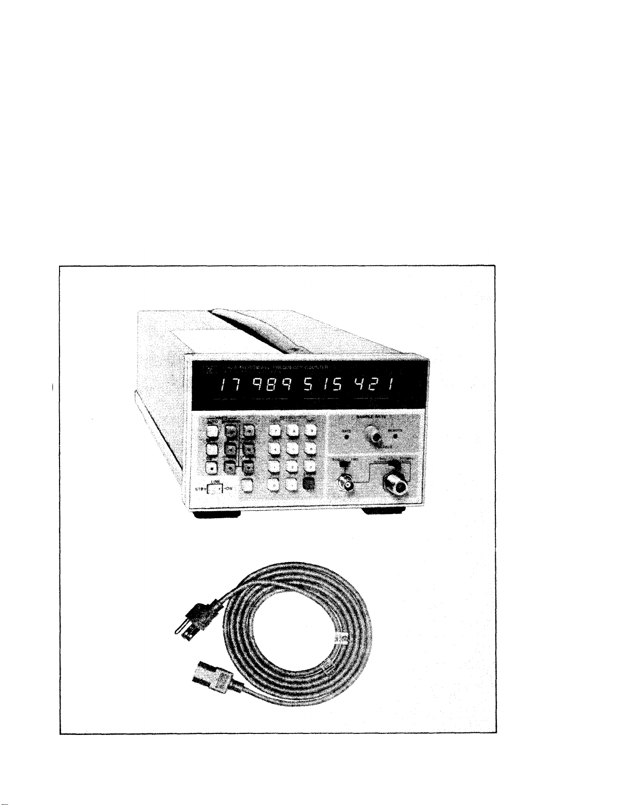
Model 5342A Microwave Frequency Counter
Line Voltage Selection . . . . . . . . . . . . . . . . . . . . . . . . . . . . . . . . . . . . . . . . . . . . .
Power Cable HP Part Numbers versus Mains Plugs Available
Hewlett-Packard Interface Bus Connection . . . . . . . . . . . . . . . . . . . . . . . . . 2-10
Front Panel Controls and Indicators
Rear Panel Controls and Connectors
Operating Procedures . . . . . . . . . . . . . . . . . . . . . . . . . . . . . . . . . . . . . . . . . . . . . .
Amplitude Measurements (Option 002) . . . . . . . . . . . . . . . . . . . . . . . . . . . . . .
DAC Operation (Option 004)
Schematic Diagram Notes . . . . . . . . . . . . . . . . . . . . . . . . . . . . . . . . . . . . . . . . .
Front Frame, A25, A26, and U1 Removale
10842A Service Accessory Kit
Extender Board (05342-60036) Test Points R1, R2, and R3
Extender Board (05342-60036) Schematic Diagram . . . . . . . . . . . . . . . . . . . . . 8-21
Harmonic Heterodyne Technique . . . . . . . . . . . . . . . . . . . . . . . . . . . . . . . . . . .
Frequency Relationships
HP 5342A Simplified Block Diagram
HP 5342A Block Diagram
Block Diagram of Synthesizer Section
Timing Diagram of A6 Search Generator Operation . . . . . . . . . . . . . . . . . .
Data Transfer Timing in A10 Circuit
0Filter Timing on A12 IF Detector
A14U21 Expanded Block Diagram . . . . . . . . . . . . . . . . . . . . . . . . . . . . . . . . . . .
Memory Arrangement . . . . . . . . . . . . . . . . . . . . . . . . . . . . . . . . . . . . . . . . . . . . .
A19, A20, and A21 Power Supply Block Diagram . . . . . . . . . . . . . . . . . . . . . . 8-70
Option 002 Amplitude Measurement Block Diagram . . . . . . . . . . . . . . . . . . 8-74
Option 003 Extended Dynamic Range Block Daigram
5342A Front (A1 Display) View
5342A Rear View . . . . . . . . . . . . . . . . . . . . . . .
5342A Top View (Assembly Locations and Adjustments) . . . . . . . . . . . . . . 8-144
5342A Bottom View, Options Installed
5342A Detailed Block Diagram
A1 Display Assembly and A2 Display Drive Assembly . . . . . . . . . . . . . . . .
Option 004 Display Driver Additions on A2 Assembly . . . . . . . . . . . . . . . . 8-151
A3 Direct Count Amplifier Assembly
A4 Offset VCO Assembly . . . . . . . . . . . . . . . .
A5 RF Multiplexer Assembly
A6 Offset Loop Amp/Search Generator Assembly . . . . . . . . . . . . . . . . . . .
A7 Mixer/Search Control Assembly
A8 Main VCO Assembly . . . . . . . . . . . . . . . . . . . . . . . . . . . . . . . . . . . . . . . . . . .
A9 Main Loop Amplifier Assembly
A10 Divide-by-N Assembly . . . . . . . . . . . . . . . . . . . . . . . . . . . . . . . . . . . . . . . .
A11 IF Limiter Assembly . . . . . . . . . . . . . . . . . . . . . . . . . . . . . . . . . . . . . . . . . . .
A12 IF Detector Assembly . . . . . . . . . . . . . . . . . . . . . . . . . . . . . . . . . . . . . . . . .
A13 Counter Assembly . . . . . . . . . . . . . . . . . . . . . . . . . . . . . . . . . . . . . . . . . . . .
A14 Microprocessor Assembly . . . . . . . . . . . . . . . . . . . . . . . . . . . . . . . . . . . . .
Option 011 A15 HP-IB Assembly
. . . . . . . . . . . . . . . . . . . . . . . . . . . . . . . . . . . . . . . . . . .
. . . . . . . . . . . . . . . . . . . . . . . . . . . . . . . . . . . . . . . . . . .
. . . . . . . . . . . . . . . . . . . . . . . . . . . . . . . . . . . . . . .
. . . . . . . . . . . . . . . . . . . . . . . . . . . . . . . . .
. . . . . . . . . . . . . . . . . . . . . . . . . . . . . . . . 3-7
. . . . . . . . . . . . . . . . . . . . . . . . . . . . . . . . . . . . . . . 3-13
. . . . . . . . . . . . . . . . . . . . . . . . . . . . . . . . . . . . . . .
. . . . . . . . . . . . . . . . . . . . . . . . . . . . . . . . .
. . . . . . . . . . . . . . . . . . . . . . . . . . . . . . .
. . . . . . . . . . . . . . . . . . . . . . . . . . . . . . . . .
. . . . . . . . . . . . . . . . . . . . . . . . . . . . . . . . . . .
. . . . . . . . . . . . . . . . . . . . . . . . . . . . . . . . . . . . . 8-142
. . . . . . . . . . . . . . . . . . . . . . . . . . . . . .
. . . . . . . . . . . . . . . . . . . . . . . . . . . . . . . . . . . . .
. . . . . . . . . . . . . . . . . . . . . . . . . . . . . . .
. . . . . . . . . . . . . . . . . . . . . . . . . . . . . . . .
. . . . . . . . . . . . . . . . . . . . . . . . . . . . . . . . .
. . . . . . . . . . . . . . . . . . . . . . . . . . . . . . . . . . .
. . . . . . . . . . . . . . . . . . . . . . . .
. . . . . . . . . . 2-2
. . . . . . . . . . . . . . . . . . . . . . . . . . . .
. . . . . . . . . . . . . . 8-20
. . . . . . . . . . . . . . . . . 8-78
. . . . . . . . . . . . . . . . . . . . . . . . . .
. . . . . . . . . . . . . . . . . . . . . . . . . .
Page
1-1
2-1
3-5
3-8
3-12
8-3
8-14
8-19
8-37
8-38
8-39
8-44
8-45
8-51
8-54
8-58
8-61
8-64
8-143
8-145
8-147
8-149
8-153
8-155
8-157
8-159
8-161
8-163
8-165
8-167
8-169
8-171
8-173
8-175
8-177
ix
Page 12

Model 5342A
List of
Figures
LIST OF FIGURES (Continued)
Figure
8-39.
8-40.
8-41.
8-42.
8-43.
8-44.
8-45.
8-46.
Title
Option 002 A16 Amplitude Measurements,
A27 Low Frequency Amplifier, and
U2 High Frequency Amplifier Assemblies
Option 003 A16 Extended Dynamic Range Assembly . . . . . . . . . . . . . . . . .
A17 Timing Generator Assembly . . . . . . . . . . . . . . . . . . . . . . . . . . . . . . . . . . .
A18 Time Base Buffer Assembly . . . . . . . . . . . . . . . . . . . . . . . . . . . . . . . . . . . .
A19, A20, A21, and A23 Power Supply Assembly . . . . . . . . . . . . . . . . . . . . .
A24 Oscillator Assemblies . . . . . . . . . . . .’ . . . . . . . . . . . . . . . . . . . . . . . . . . . . .
A25 Preamplifier Assembly
A26 Sampler Driver Assembly . . . . . . . . . . . . . . . . . . . . . . . . . . . . . . . . . . . . . .
. . . . . . . . . . . . . . . . . . . . . . . . . . . . . . . . . . . . . . . .
. . . . . . . . . . ....
Page
8-179
8-181
8-183
8-185
8-187
8-189
8-191
8-193
x
Page 13

SECTION O
INSTRUCTIONS
TM 11-6625-3014-14
0-1.
SCOPE.
This manual describes Microwave Frequency Counter TD-1225A(V)l/U (fig. l-l)
and provides maintenance instructions. Throughout this manual, the TD-1225A(V)l/U
is refered to as the Hewlett-Packard (HP) Model 5342A.
0-2.
whether there are new
INDEXES OF PUBLICATIONS.
a.
DA Pam 310-4.
Refer to the latest issue of DA Pam 310-4 to determine
editions,
changes, or additional publications pertaining
to the equipment.
b.
DA Pam 310-7.
Refer to DA Pam 310-7 to determine whether there are
modification work orders (MWO’S) pertaining to the equipment.
0-3.
forms,
FORMS AND RECORDS.
a.
Reports of Maintenance and Unsatisfactory Equipment. Maintenance
records,
and reports which are used by maintenance personnel at all
levels of maintenance are listed in and prescribed by TM 38-750.
b.
Report of Packaging and Handling Deficiencies.
Fill out and forward
SF 364 (Report of Discrepancy (ROD))as prescribed in AR 735-11-2/DLAR
4140.55/NAVSUPINST 4610.33B/AFR 75-18/MCO p4610.19C and DLAR 4500.15.
c. Discrepancy in Shipment Report (DISREP) (SF 361). Fill out and
forward Discrepancy in Shipment Report (DISREP) (SF 361) as prescribed in
AR 55-38/NAVSUPINST 4610.33B/AFR 75-18/MCO P4610.19C and DLAR 4500.15.
0-4.
REPORTING OF EQUIPMENT IMPROVEMENT RECOMMENDATIONS (EIR).
EIR’s will be prepared using DA Form 2407, Maintenance Request.
Instructions for preparing EIR’s are provided in TM 38-750, The Army
Maintenance Management System.
EIR’s should be mailed directly to
Commander, US Army Communications and Electronics Materiel Readiness Command,
ATTN:
DRSEL-ME-MQ, Fort Monmouth, New Jersey 07703.
A reply will be
furnished directly to you.
0-5.
ADMINISTRATIVE STORAGE.
Administrative storage of equipment issued to and used by Army activities
shall be in accordance with TM 740-90-1.
0-6.
DESTRUCTION OF ARMY ELECTRONICS MATERIEL.
Destruction of Army electronics materiel to prevent enemy use shall be in
accordance with TM 750-244-2.
0-1
Page 14
Model 5342A
General Information
SECTION I
GENERAL INFORMATION
1-1. INTRODUCTION
1-1. This manual provides operating and service information for the Hewlett-Packard Model
5342A Microwave Frequency Counter, shown in Figure 1-1.
1-3. SPECIFICATIONS
1-4. Specifications of the 5342A are listed in Table 1-1.
Figure 1-1. Model 5342A Microwave Frequency
Counter
1-1
Page 15
Model 5342A
General Information
INPUT 1:
Frequency range: 500 MHz to 18 GHz
Sensitivity:
500 MHz to 12.4 GHz -25 dBm
12.4 GHz to 18 GHz
Maximum input: +5 dBm (see Options 002,003
for higher level).
Dynamic range:
500 MHz to 12.4 GHz 30 dB
12.4 GHz to 18 GHz
Impedance: 50 ohms, nominal
Connector:
Damage level: +25 dBm, peak
Coupling:
SWR:
<2:1, 500 MHz—10 GHz
<3:1, 10 GHz—18 GHz
FM tolerance:
FM
(wide):
CW
(normal): 20 MHz p-p worst case.
For modulation rates from dc to 10 MHz.
AM
tolerance:
the minimum signal level is not less than the
sensitivity specification.
Automatic amplitude discrimination: Automati-
cally measures the largest of all signals present, providing that signal is 6 dB above any
signal within 500 MHz; 20dB above any signal,
500 MHz—18 GHz.
Modes of operation:
Automatic:
and displays highest level signal within sensitivity range.
Manual:
±50 MHz to true value.
Acquisition time:
Automatic mode: Normal FM 530 ms worst
case; wide FM 2.4 s worst case.
Manual mode:
INPUT 2:
Frequency range:
Count.
Sensitivity:
50 10 Hz to 520 MHz 25 mV rms,
1 M 10 Hz to 25 MHz 50 mV rms.
Impedance:
nominal.
Coupling: ac
Connector: Type BNC female.
Maximum input:
dc fuse protected; 1 MW 200V dc +5.0V rms.
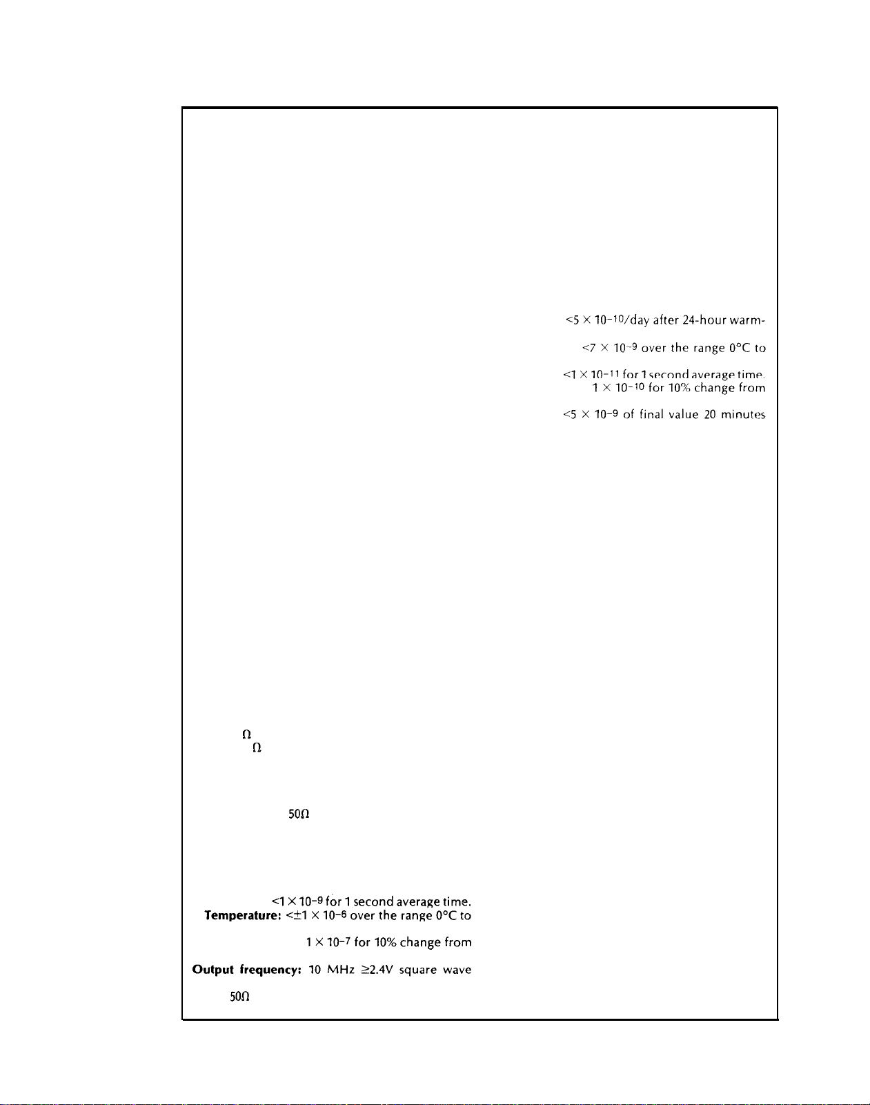
Crystal frequency: 10 MHz
Stability:
Aging rate: <1 X 10-
Short term:
50°C.
Line variation:
nominal.
(TTL compatible); 1.5V peak-to-peak into
50W available from rear panel BNC.
Table 1-1. Model 5342A Specifications
INPUT CHARACTERISTICS
-20 dBm
25 dB
Precision Type N female
dc to load, ac to instrument.
Switch selectable (rear panel)
50 MHz p-p worst case.
Any modulation index provided
Counter automatically acquires
Center frequency entered to within
80
ms after frequency entered.
10 Hz to 520 MHz Direct
Selectable: 1 MW, <50 pF or 50W
50Ω
3.5V rms (+24 dBm) or 5V
TIME BASE
7
per month.
External time base:
Requires 10 MHz, 2.0V peakto-peak sine wave or square wave into 1 KW
via rear panel BNC connector.
Switch
selects either internal or external time base.
OPTIONAL TIME BASE
(OPTION 001)
Option 001 provides an oven-controlled crystal
oscillator time base, 10544A (see separate data
sheet), that results in better accuracy and longer
periods between calibration.
Crystal frequency: 10 MHz
Stability:
Aging rate:
up.
Temperature:
50°C.
Short term:
Line variation:
nominal.
Warm-up:
after turn-on, at 25°C.
AMPLITUDE MEASUREMENT
(OPTION 002)
Option 002 provides the capability of measuring
the amplitude of the incoming sine wave signal,
and simultaneously displaying its frequency (MHz)
and level (dBm). The maximum operating level
and the top end of dynamic range are increased to
+20 dBm. Amplitude offset to 0.1 dB resolution
may be selected from front panel pushbuttons.
INPUT 1:
Frequency range: 500 MHz—18 GHz,
Dynamic range (frequency and level):
-22 dBm to +20 dBm 500 MHz to 12.4 GHz
-15 dBm to +20 dBm 12.4 GHz to 18 GHz
Maximum operating level: +20 dBm
Damage level: +25 dBm, peak
Resolution: 0.1 dB
Accuracy:
±1.5 dB (excluding mismatch
uncertainty).
SWR:
<2:1 (amplitude measurement).
<5:1 (frequency measurement).
Measurement time: 100 ms + frequency mea-
surement time.
Display:
Simultaneously displays frequency to 1
MHz resolution and input level. (Option 011
provides full frequency resolution on HP-IB
output.)
INPUT 2:
(500 impedance only)
Frequency range: 10 MHz—520 MHz
Dynamic range (frequency and level):
-17 dBm to +20 dBm.
Damage level: +24 dBm, peak
Resolution: 0.1 dBm.
Accuracy:
1.5 dB (excluding mismatch
uncertainty).
SWR:
<1.8:1
Measurement time: 100 ms + frequency mea-
surement time.
Display:
Simultaneously displays frequency to 1
MHz resolution and input level.
1-2
Page 16

Model 5342A
General Information
Table 1-1.
Model 5342A Specifications (Continued)
EXTENDED DYNAMIC RANGE
(OPTION 003)
Option 003 provides an attenuator that automatically extends the dynamic range of operation for
input 1.
INPUT 1:
Frequency range:
500
MHz to
18
GHz
Sensitivity:
500 MHz to 12.4 GHz -22 dB
12.4 GHz to 18 GHz
Maximum operating level:
-15 dBm
+20
dBm.
Dynamic range:
500 MHz to 12.4 GHz 42 dB
12.4 GHz to 18 GHz
Damage level:
SWR:
<5:1
+25
dBm, peak
35 dB
DIGITAL-TO-ANALOG CONVERTER
(OPTION 004)
Option 004 provides the ability to convert any
three consecutive displayed digits into an analog
voltage output. A display of
put; 999 produces 9.99V full scale.
∅∅∅
produces ∅ V out-
Accuracy: ±5 mV, ±0.3 mV/°C (from 25°C)
Conversion Speed:
reading.
Resolution:
10 mV
Output: 5 mA. Impedance <1.0 ohm.
Connector: Type BNC female on rear panel.
Accuracy: ±1 count ± time base error.
GENERAL
Resolution:
1 MHz.
Residual stability:
common time base or counter uses external
higher stability time base, <4 X 10-
typcial.
Front panel pushbuttons select 1 Hz to
When counter and source use
11
rms
Display: 11-digit LED display, sectionalized to
read GHz, MHz, kHz, and Hz.
Self-check:
buttons. Measures 75 MHz for resolution
chosen.
Selected from front panel push-
Frequency offset: Selected from front panel
pushbuttons. Displayed frequency is offset by
entered value to 1 Hz resolution.
Sample rate: Variable from less than 20 ms be-
tween measurements to HOLD which holds
display indefinitely.
IF out: Rear panel BNC connector provides 25
MHz to 125 MHz output of down-converted
microwave signal.
Operating temperature:
Power requirements: 100/120/220/240V rms, +5%,
-10%, 48—66 Hz; 100 VA max.
Accessories furnished:
Size: 133 mm H X 213 mm W X 498 mm D
0°C
Power
to
50°C.
cord,
229
cm
(7½
ft.)
Weight: Net 9.1 kg (20 Ibs.).
Shipping 12.7 kg (28 Ibs.).
1-5. SAFETY CONSIDERATIONS
1-6. This product is a Safety Class I instrument (provided with a protective earth terminal). Safety
information pertinent to the operation and servicing of this instrument is included in appropriate
sections of this manual.
1-7. INSTRUMENT IDENTIFICATION
1-8. Hewlett-Packard instruments have a 2-section, 10-character serial number (0000A00000),
which is located on the rear panel.
The four-digit serial prefix identifies instrument changes. If
the serial prefix of your instrument differs from that listed on the title page of this manual, there
are differences between this manual and your instrument. Instruments having higher serial
prefixes are covered with a “Manual Changes” sheet included with this manual. If the change
sheet is missing, contact the nearest Hewlett-Packard Sales and Service Office listed at the back of
this manual. Instruments having a lower serial prefix than that listed on the title page, are covered
in Section
VII.
1-9. ACCESSORIES
1-10. Table 1-2 lists accessory equipment supplied and Table 1-3 lists accessories available.
Table 1-2. Equipment Supplied
DESCRIPTION HP PART NUMBER
Detachable Power Cord 229 cm (7½ feet long)
8120-1378
1-3
Page 17

Model 5342A
General Information
Table 1-3. Accessories Available
DESCRIPTION
Bail Handle Kit 5061-2002
Rack Mounting Adapter Kit (Option 908) 5061-0057
Rack Mounting Adapter Kit with slot for access
to front connectors from rear.
Transit Case 9211-2682
Service
Accessory Kit (refer to paragraph
Microwave Attenuators
Signature Analyzer
1-16)
HP PART NUMBER
K70-59992A
Model 10842A
Model 8491B, 8494/5/6H
Model 5004A
1-11. DESCRIPTION
1-12. The 5342A Microwave Frequency Counter measures the frequency of signals in the range
of 10 Hz to 18 GHz, with a basic sensitivity of -25 dBm. Signals in the frequency range of 10 Hz to
500 MHz are measured by the direct count method. Signals in the frequency range of 500 MHz to
18 GHz are down-converted to an IF by a heterodyne conversion technique for application to the
counter circuits. The unique conversion technique employed results in high sensitivity and FM
tolerance in addition to automatic amplitude discrimination. The counted IF is added to the local
oscillator frequency to determine the unknown frequency for display.
1-13. OPTIONS
1-14. Options available with the 5342A are described in Table 1-1 and paragraph 3-57. If an
option is included in the initial order, it will be installed at the factory and ready for operation
upon receipt. If an option is ordered
for field installation it will be supplied as a retrofit kit. Refer
to Section II for kit part numbers and installation instructions.
1-15. SERVICE EQUIPMENT AVAILABLE
1-16. Extender boards are available for servicing printed circuit assemblies while extended from
the instrument. The extender boards allow assemblies to be extended from their plug-in con-
nectors for monitoring with appropriate test equipment. Extender boards for each assembly are
supplied in Service Accessory Kit 10842A as described in paragraph 8-46.
1-17. RECOMMENDED TEST EQUIPMENT
1-18. The test equipment listed in Table 1-4 is recommended for use during performance tests,
adjustments, and troubleshooting. Substitute test equipment may be used if it meets the required
characteristics listed in the table.
1-4
Page 18

Table 1-4 Recommended Test Equipment
Model 5342A
General Information
INSTRUMENT
Oscilloscope
Signal Generator
Spectrum Analyzer RF inputs from 1 MHz—500 MHz T,A,P
DC Voltmeter 20V Range, 0.05V Resolution T,A
AC Voltmeter 10 MHz-350 MHz T,A
AC Voltmeter 100 kHz, 1% accuracy
Logic State Analyzer HP 1740A compatibility
Signature Analyzer 5342A compatibility T
Power Splitter DC—18 GHz
Logic Pulser
Current Tracer
Logic Probe
Step Attenuator
AP Clips (4) Clip for 14 pin/16 pin IC’s
Isolation Transformer 120V IN — Isolated 120V OUT
Extender Boards 2 X 10 pin
REQUIRED
CHARACTERISTICS
100 MHz bandwidth
10 Hz—10 MHz
10 MHz—2.4 GHz
2 GHz—18 GHz
USE*
T,A,OV,P
T,A,OV,P HP 651B
A (Opt. 002)
OV,P
TTL compatibility
1 mA—1 A range
TTL compatibility
DC—18 GHz 10 dB steps
2 X 12 pin
2 X 15 pin HP P/N 05342-60032
2 X 18 pin (2)
OV,P
2 X 22 pin (2)
X 24 pin
2
A 14 Extender
A15 Extender
Power Meter
Power Sensor
50Ω Termination
Microwave Amplifier 1 GHz, >+20 dBm Output
Signal Generator
Signal Generator
Swept Frequency Analyzer
15 MHz—18GHz Modulator HP 8755B compatibility
15 MHz-18 GHz Detectors 0.1—18 GHz
(2 required)
Oscilloscope Mainframe HP 8755B compatibility
Directional Coupler 2—18 GHz
Directional Coupler 100—500 MHz
Signal Generator (Two Microwave sources needed
Mainframe
Bus System Analyzer
*T = Troubleshooting
A = Adjustments
OV = Operational Verification
P = Full Performance Testing
10 MHz—18 GHz
10 MHz—18 GHz
-30 dBm to +20 dBm
DC—18 GHz
100 MHz, +20 dBm
>100 MHz,
100 MHz—18 GHz
for automatic amplitude
discrimination test — see
paragraph 4-35)
Control HP-IB lines T (Opt. 011) HP 59401A
>+20 dBm
A,OV,P HP 436A
A,OV,P HP 8481A
P (Opt.
A (Opt. 002) HP 8601A
P,OV,
(Option 002)
RECOMMENDED
MODEL
HP 1740A
HP 8620C/86222A
HP 8620C/86290A
HP 141T/8552A/8554B
HP 3465A
HP 3406A
HP 3400A
T HP 1607A (use
T HP 546A
T HP 547A
T HP 545A
T HP P/N 1400-0734
T Allied Electronics
T
P
with HP 1740A)
HP 5004A
HP 11667A
HP 8495B
P/N 705-0048
HP P/N 05342-60030
HP P/N 05342-60031
HP
P/N 05342-60033
HP P/N 05342-60034
HP P/N 05342-60035
HP P/N 05342-60036
HP
P/N 05342-60039
HP 909A
(Option 012)
002) HP 489A
HP 3312A
P
P
P
P
P
P
P
HP 8755B
HP 11665B
HP 11664A
HP 182T
HP 11692D
HP 778D
HP 8620C Mainframe
1-5
Page 19
Model 5342A
Installation
SECTION II
INSTALLATION
2-1. INTRODUCTION
2-2. This section contains information for unpacking, inspection, storage, and installation.
2-3. UNPACKING AND INSPECTION
2-4. If the shipping carton is damaged, inspect the instrument for visible damage (scratches,
dents, etc.). If the instrument is damaged, notify the carrier and the nearest Hewlett-Packard
Sales and Service Office immediately (offices are listed at the back of this manual). Keep the
shipping carton and packing material for the carrier’s inspection. The Hewlett-Packard Sales
and Service Office will arrange for repair or replacement of your instrument without waiting for
the claim against the carrier to be settled.
2-5. INSTALLATION REQUIREMENTS
CAUTION
Before connecting the instrument to ac power lines,
be sure that the voltage selector is properly
positioned as described below.
2-6.
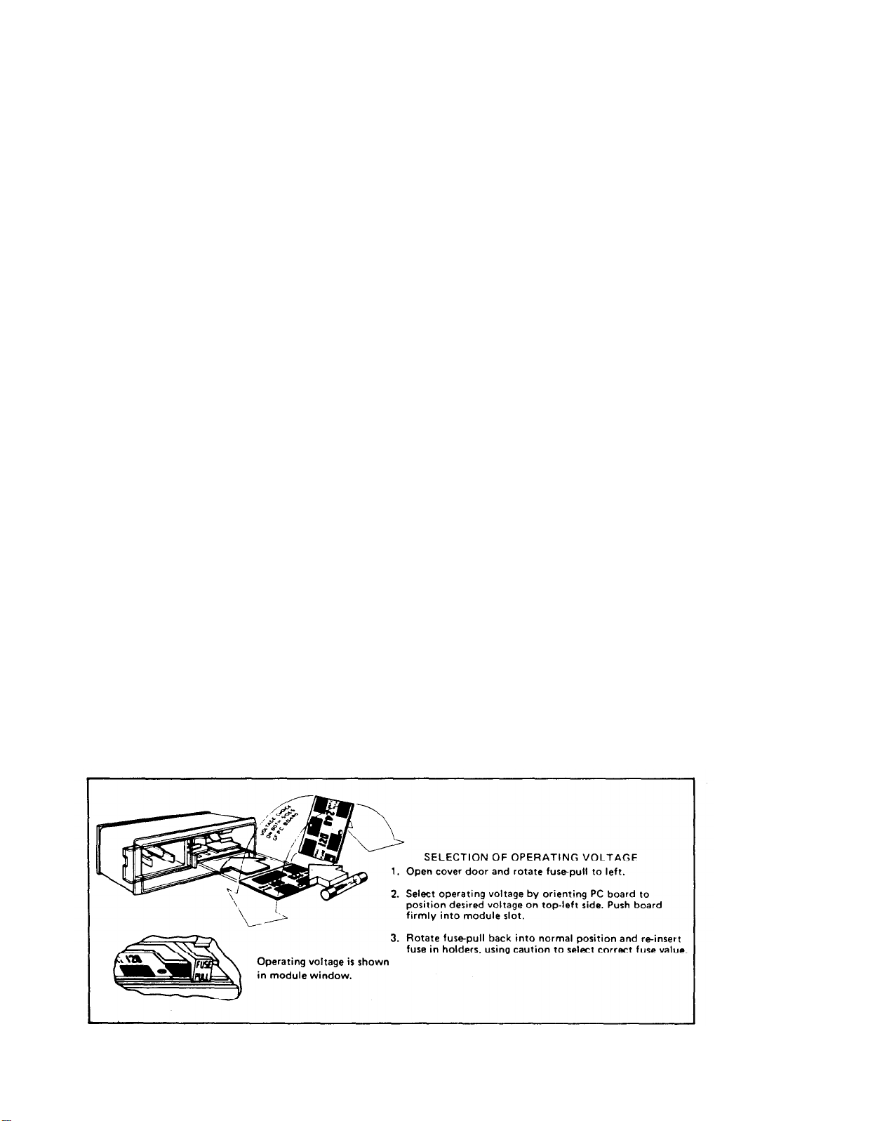
LINE VOLTAGE REQUIREMENTS. The 5342A is equipped with a power module that con-
tains a printed-circuit line voltage selector to select 100- 120-, 220-, or 240-volt ac operation.
Before applying power, the pc selector must be set to the correct position and the correct fuse
must be installed as described
2-7. Power line connections are selected by the position of the plug-in circuit card in the
module. When the card is plugged into the module, the only visible markings on the card indicate the line voltage to be used. The correct value of line fuse, with a 250-voIt rating, must be
installed after the card is inserted. This instrument uses a 0.75A fuse (HP Part No. 2110-0360) for
100/120-volt operation; a 0.375A fuse (HP Part No. 2110-0421) for 220/240-volt operation.
2-8. To convert from one line voltage to another, the power cord must be disconnected from
the power module before the sliding window covering the fuse and card compartment can be
moved to expose the fuse and circuit card. See
below.
Figure 2-1.
Figure 2-1. Line Voltage Selection
2-1
Page 20
Model 5342A
Installation
2-9. Power Cable
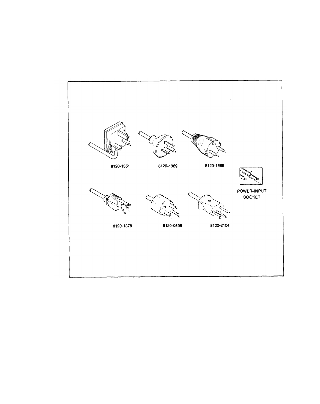
2-10. The 5342A is shipped with a three-wire power cable. When the cable is connected to an appropriate ac power source, this cable connects the chassis to earth ground. The type of power cable plug shipped with each instrument depends on the country of destination. Refer to Figure 2-2 for the part numbers of the power cable and plug configurations available.
2-2
Figure 2-2. Power Cable HP Part Numbers versus Mains Plugs Available
WARNING
BEFORE SWITCHING ON THIS INSTRUMENT, THE
PROTECTIVE EARTH TERMINALS OF THIS INSTRU-
MENT MUST BE CONNECTED TO THE PROTECTIVE
CONDUCTOR OF THE (MAINS) POWER CORD. THE
MAINS PLUG SHALL ONLY BE INSERTED IN A
SOCKET OUTLET PROVIDED WITH A PROTECTIVE
EARTH CONTACT, THE PROTECTIVE ACTION MUST
NOT BE NEGATED BY THE USE OF AN EXTENSION
CORD (POWER CABLE) WITHOUT A PROTECTIVE
CONDUCTOR (GROUNDING).
Page 21

Model 5342A
Installation
2-11. Operating Environment
2-12. TEMPERATURE. The 5342A may be operated in temperatures from 0°C to +55°C.
2-13. HUMIDITY. The 5342A may be operated in environments with humidity up to 95%. However, it should be protected from temperature extremes which cause condensation in the
instrument.
2-14. ALTITUDE. The 5342A may be operated at altitudes
2-15. STORAGE AND SHIPMENT
2-16. Environment
2-17. The instrument may be stored or shipped in environments within the following limits:
TEMPERATURE . . . . . . . . . . . . . . . . . -40°C to +75°C
HUMIDITY . . . . . . . . . . . . . . . . . . . . . . . . . .
ALTITUDE . . . . . . . . . . . . .
2-18. The instrument should also be protected from temperature extremes which cause
condensation within the instrument.
2-19. Packaging
2-20. ORIGINAL PACKAGING. Containers and materials identical to those used in factory
packaging are available through Hewlett-Packard offices. If the instrument is being returned to
Hewlett-Packard for servicing, attach a tag indicating the type of service required, return address,
model number, and full serial number. Also, mark the container FRAGILE to ensure careful
handling. In any correspondence, refer to the instrument by model number and full serial
number.
2-21. OTHER PACKAGING. The following general instructions should be used for repacking
with commercially available materials:
7,620 metres (25,000 feet)
up to 4,600 metres (15,000 feet).
Up to 95%
Wrap instrument in heavy paper or plastic. (If shipping to Hewlett-Packard office or
a.
service center, attach tag indicating type of service required, return address, model
number, and full serial number.)
b. Use strong shipping container. A double-wall carton made of 350-pound test material is
adequate.
c.
Use a layer of shock-absorbing material 70 to 100 mm (3-to 4-inch) thick around all sides
of the instrument to provide firm cushioning and prevent movement inside container.
Protect control panel with cardboard.
d. Seal shipping container securely.
Mark shipping container FRAGILE to ensure careful handling.
e.
f. In any correspondence, refer to instrument by model number
2-22. FIELD INSTALLATION OF
2-23. Procedures for field installation of Options 001,002,003,004, and 011 are described in the
OPTIONS
and full serial number.
following paragraphs.
2-3
Page 22

Model 5342A
Installation
2-24. Part Numbers for Ordering Option Kits
2-25. To obtain the necessary parts for installation of an option, order by part number as listed
below (refer to Section VI for ordering information):
Option
001
002
003
*004
001
If the instrument in which Option 004 is to be installed
has a series number 1812 or lower, the U7 ROM on
A14 Microprocessor will have to be replaced. Order
U7 ROM Part Number 1818-0706 to replace the old
U7 ROM (1818-0331).
2-26. Installation of 10 MHz Oscillator Option 001
2-27. Option 001 consists of oven-controlled crystal oscillator time base 10544A, which has a pc
card connector. Option 001 is installed in the same connector on the motherboard as the standard oscillator (A24). See Figure 8-44. To install Option 001, proceed as follows:
High Stability Time Base HP Model 10544A
Amplitude Measurement
Extended Dynamic Range 05342-60201 (Kit)
Digital-to-Analog Converter
HP-IB I/O 05342-60019 (HP-IB Assy.)
Name Part Number
05342-60200 (Kit)
05342-60202 (Kit)
05342-60029 (HP-IB Input Assy.)
*NOTE
a.
Remove the standard oscillator from A24 connector.
b. Install Option 001 oscillator into A24 connector.
Attach Option 001 oscillator to the motherboard by means of two 6/32X5/16 pan head
c.
screws. Install the screws from the bottom of the motherboard using star washers.
d. Perform Option 001 oscillator adjustment as described in paragraph 5-32.
2-28. Installation of Amplitude Measurement Option 002
2-29. Option 002 consists of U2 High Frequency Amplitude assembly and A27 Low Frequency
Amplitude Assembly modules and the A16 Amplitude Assembly pc board. U2 is connected to the
high frequency input of the 5342A, A27 is connected to the low frequency input and both of the
modules are connected to the A16 board by the coax wires supplied. See photo of installed
option, Figure 8-22, and schematic diagram, Figure 8-39. To install the components proceed as
follows:
NOTE
The parts that comprise this option are listed in Table 6-5.
a.
Remove the top and bottom covers and top plate from instrument.
b. Place instrument top down.
c.
At inside front panel, disconnect cables from A1J1,J1J3,J25J1 (IF OUT lNT), and A25J2 (IF
OUT EXT).
d. Solder one end of the white/red/green 14-inch wire (8120-0483) to AT1 feedthrough
capacitor terminal on A25 Preamplifier assembly.
2-4
Page 23
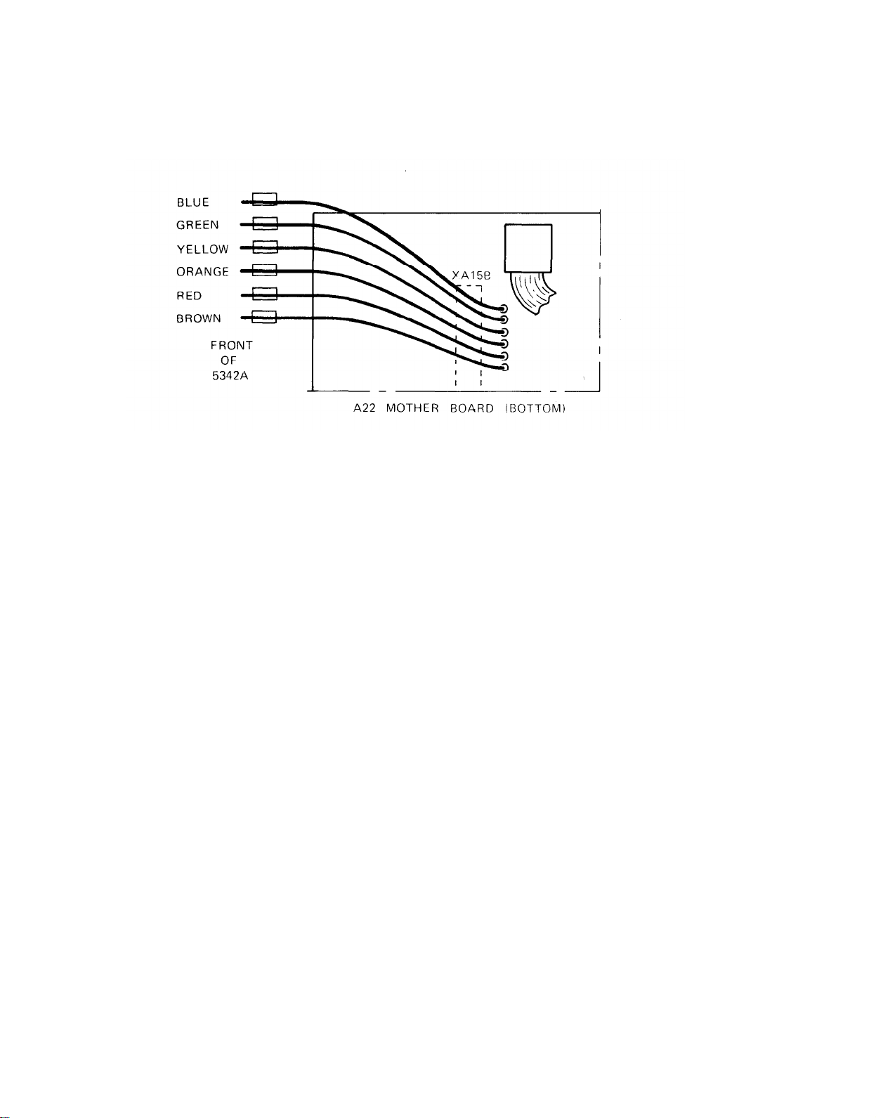
Install coax assembly 8120-2268 through A22 motherboard from top of instrument at A16
e .
slot. Place the wires through the holes as shown below:
NOTE
Model 5342A
Installation
Prior to installing A27 Low Frequency
Amplitude Assembly, connect the wires as
described below.
f.
Solder one
capacitor terminal on A27.
Place heat shrinkable tubing (0890-0983) over connection at C7,
g.
h.
Place heat shrinkable tubing (0890-0983) over three of the coax wires (red, blue, and
green) that were installed in step e. and solder
Coax
Red
Blue
Green
Apply heat to shrink the tubing at the connections made in step g and h.
i.
Remove attaching nut from front panel N-type input connector and disconnect rigid
j.
coax W1 from J1 on U1 Sampler. Remove W1 from instrument.
Mount A27 Low Frequency Amplitude Assembly in the recessed angle of the casting
k.
behind front frame, see Figure 8-22. Attach A27 to casting with two pan head screws
supplied. Place a star washer under the other screw.
The wire previously soldered to A27C10 has a black ground wire attached. Solder the end
l.
of this black wire to the ground lug installed in preceding step.
end of the black/white/blue 14-inch wire (8120-0471) to C7 feedthrough
these wires to the terminals listed below:
Terminal
A27C10
A27C9
A27C8
Solder the free end of white/red/green wire (other end connected to A25AT1 in step d)
m.
to A22 motherboard at XA16B, pin 3 (ATT).
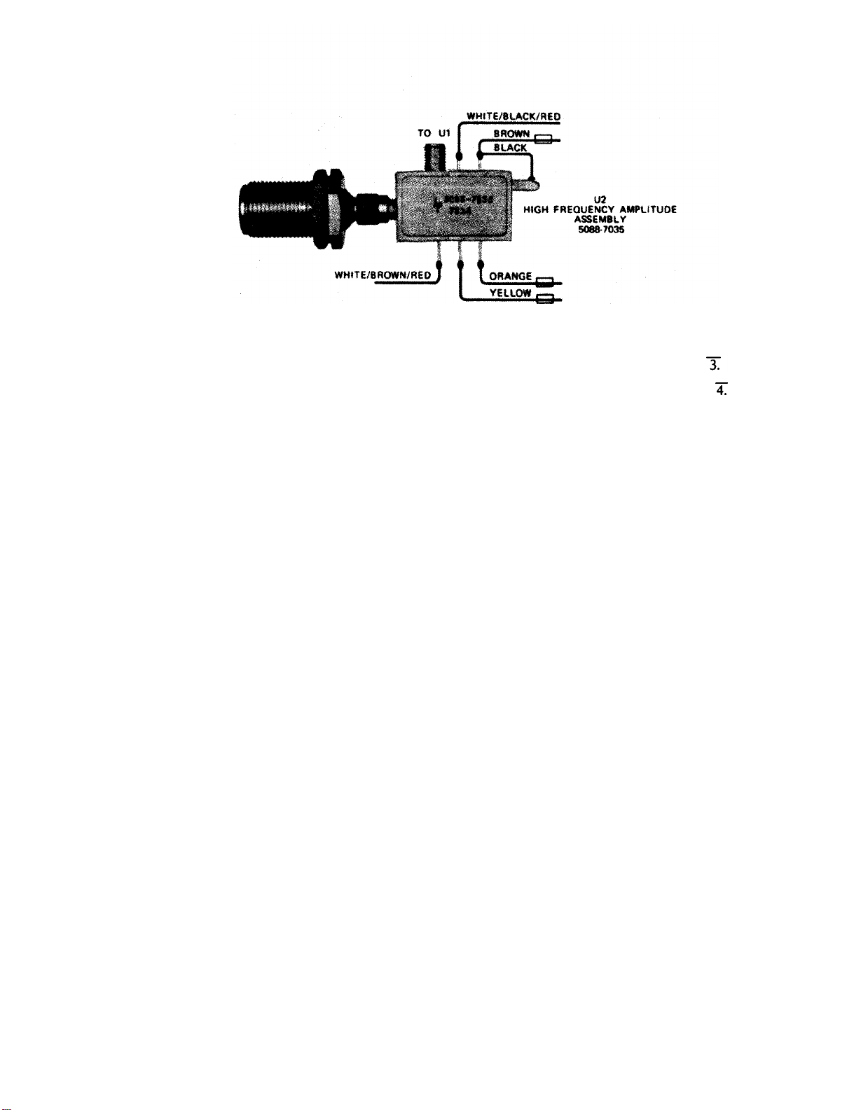
NOTE
Prior to installing U2 High Frequency Amplitude
Assembly, connect the color-coded wires as shown
below. Place heat shrinkable tubing (0890-0983 for
coax and 0890-0706 for single wires) over all connections to U2.
2-5
Page 24
Model 5342A
Installation
n.
o.
p.
q.
r.
s.
Connect rigid coax (8120-2516) from U2 High Frequency Amplitude Assembly to J1 on
Sampler U1. Install U2 input connector through front panel. Fasten with attaching nut.
Solder white/black/red wire (from U2) to A22 motherboard XA16B, pin
Solder white/brown/red wire (from U2) to A22 motherboard XA16B, pin
Harness the coax cables and wires with tie wraps supplied.
Connect cable 05342-60119 from A27J1 to A1J3.
Connect cable A1J3/A27J2 to A27J2.
Reconnect A1J1,J1 (IF OUT INT) and J2 (IF OUT EXT) and harness with tie wrap.
t.
Harness the white cables with tie wraps supplied.
u.
NOTE
The ROM and U2 High Frequency Amplitude
Assembly are supplied as a matched pair and are
included
(05342-80005).
v.
Install the ROM (supplied with option) into U3 socket on A16 (05342-60038) board.
Replace resistor R2 on A16 board with a resistor of the value labeled on U2 assembly.
w.
Insert the plug of 8120-2268 cable into mating socket on A16 board (05342-60038) and
x.
install A16 into connector XA16.
Perform the Option 002 adjustments listed under paragraph 5-33 through 5-39 of this
y.
manual.
Perform the operational verification procedures in paragraphs 4-14, 4-15, and 4-17
z.
of this manual.
under one replaceable part number
NOTE
If the instrument does not meet the specified
accuracy of ±1.5 dB as described in paragraph 4-14,
perform the following procedures.
Replace resistor R6 from the A27 Low Frequency Amplitude Assembly and replace with a
resistor of a higher or lower value as shown below. For lower power readings increase the
value and for higher power readings decrease the value of resistor R6 as follows:
2-6
dB Change
0.2
0.4
0.6
0.8
1.0
R6 Changes
(ohms)
10
20
30
40
50
Page 25
Model 5342A
Installation
2-30.
Installation of Extended Dynamic Range Option 003
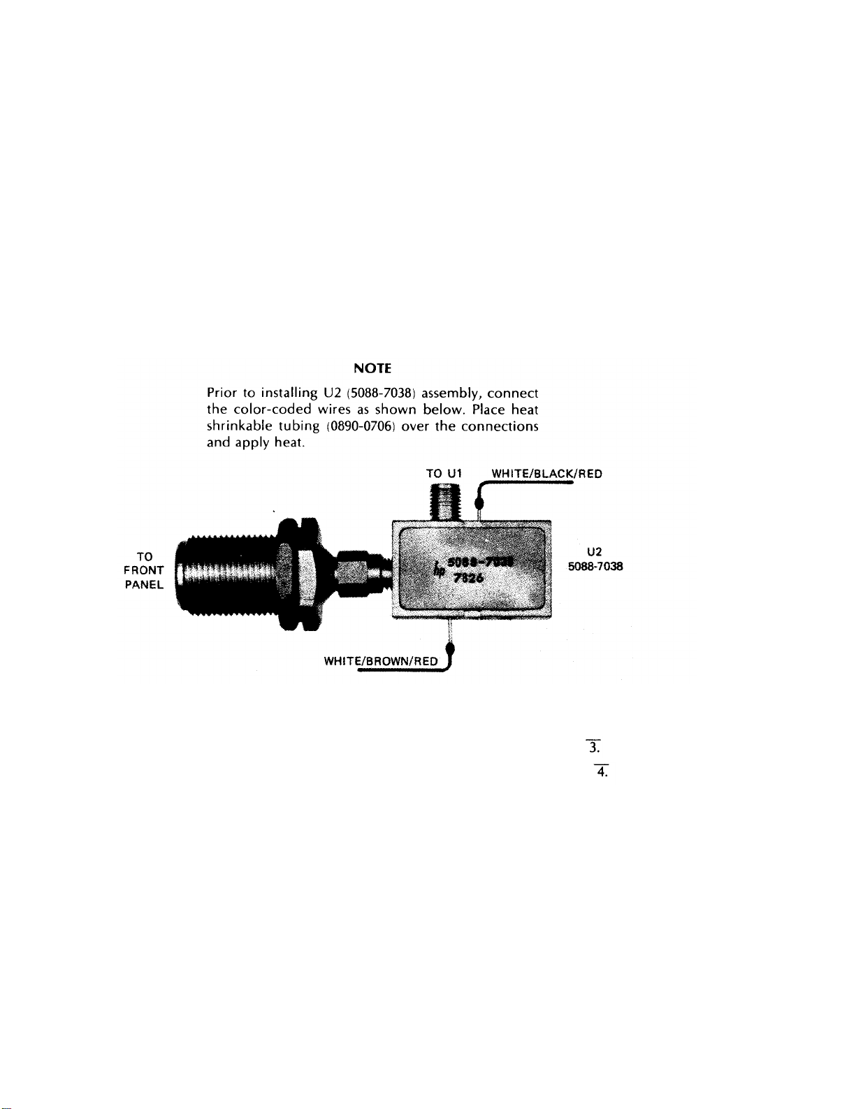
2-31. Option 003 consists of A16 Extended Dynamic Range Assembly (05342-60037) and U2
Attenuator Assembly (5088-7038). See Figure 8-22 for location of U2 (Option 002 or 003).
NOTE
The parts that comprise this option are listed at the
end of Table 6-6.
Remove the top and bottom covers and top plate from instrument.
a.
Place instrument top down.
b.
At inside front panel, disconnect cable from A1J1,A1J3,A25J1 (IF OUT INT), and A25J2
c.
(IF OUT EXT).
Solder one end of the white/red/green 14-inch wire (8120-0483) to AT1 feedthrough
d.
capacitor terminal on A25 Preamplifier Assembly.
Solder free end of white/red/green wire (other end connected to A25AT1 in step d) to
e.
A22 Motherboard at XA16B, pin 3 (ATT).
Solder white/bIack/red wire (from U2) to A22 Motherboard XA16B, pin
f.
Solder white/brown/red wire (from U2) to A22 Motherboard XA16B, pin
g.
h.
Remove the N-type input connector from front panel and replace with U2 (5088-7038).
Connect rigid coax (supplied) from U2 to J1 on Sampler U1.
i.
Install A16 board (05342-60037) into XA16 connector.
j.
Perform the operational verification procedures in paragraphs 4-13 and 4-16
k.
of this manual.
2-32.
Installation of Digital-to-Analog Conversion (DAC) Option 004
2-33. Option 004 consists of an A2 Display Driver Assembly (05342-60028) that contains DAC
circuitry added to the standard A2 circuit. Interconnecting wires are included with the Option
004 retrofit kit (05342-60202). Procedures for installation of Option 004 are as follows:
2-7
Page 26
Model 5342A
Installation
a.
b.
Remove top and bottom covers, front frame and A1-A2 assemblies. Refer to disassembly
procedures, paragraph 8-22.
Replace the original A2 board (05342-60002) with Option 004 A2 board (05342-60028) and
reassemble unit.
If the series number of the instrument is
c.
1812 or lower, the U7 ROM, 1818-0331 on the
A14 Microprocessor board will have to be replaced with U7 ROM, 1818-0706 as described
in step d. If instrument has the
1818-0706 ROM, proceed to step e.
CAUTION
ROM U7 is a large-scale MOS IC. Its inputs are
susceptible to damage by high voltage and by static
charges. Particular care should be exercised when
servicing this IC or handling it under conditions
where static charges can build up.
Remove top plate from 5342A. Remove A14 Microprocessor and replace ROM U7 part
d.
number 1818-0331 with part number 1818-0706. Install A14.
At bottom of 5342A connect coax cable to the connector at the bottom rear of A2 board
e.
labeled D/A OUTP. Solder the other end of this cable to the DAC OUT connector on the
rear paneI.
f.
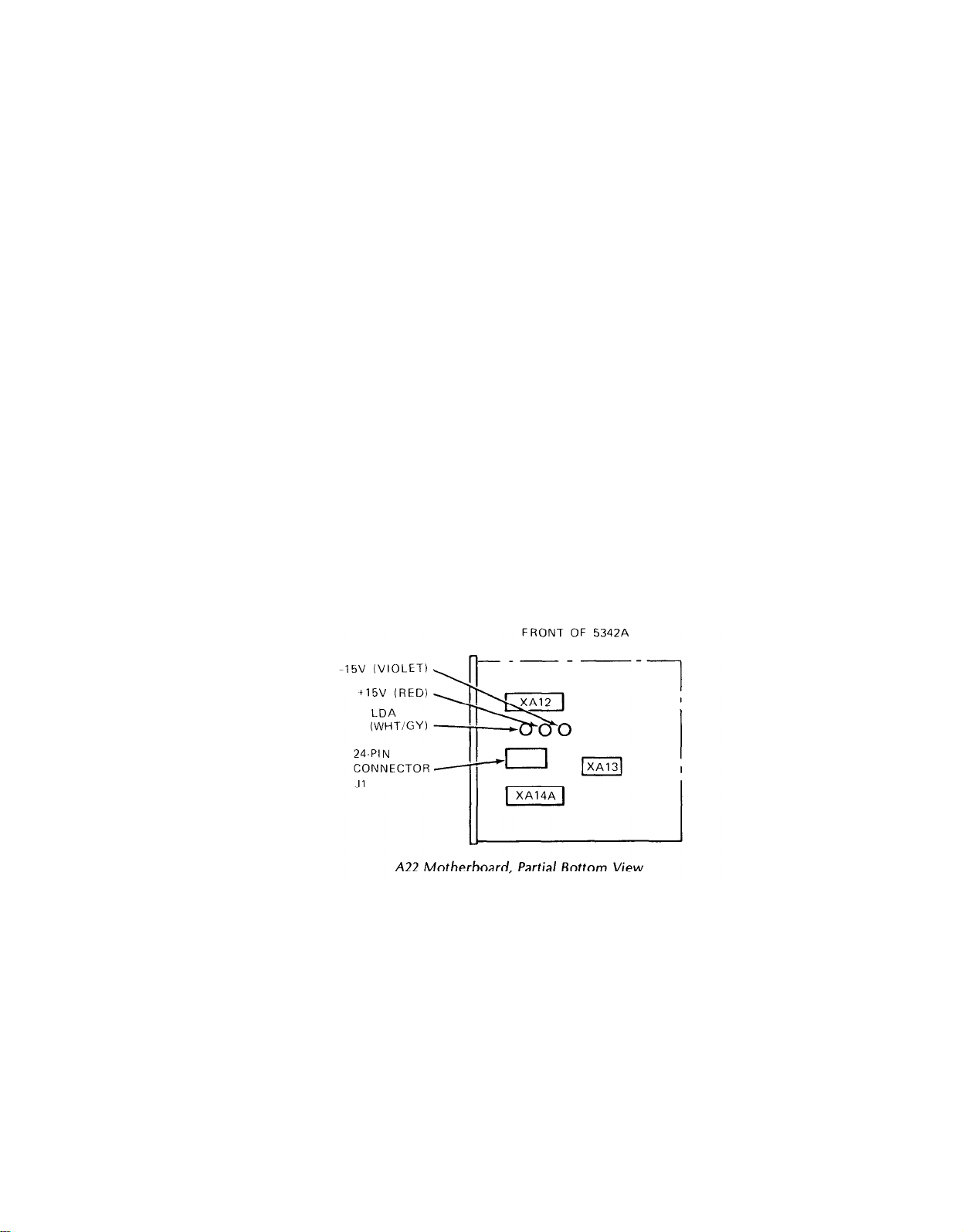
Connect the white/gray wire to the pin (push-on) labeled LDA at bottom rear of A2
Display Driver board. Solder other end of wire to LDA terminal on A22 Motherboard as
shown in figure below.
Connect red wire (+15V) and violet wire (-15V) to the proper terminals (push-on pins) on
g.
A2 Display Driver board (see
Figure 8-25, component locator for location). Connect
other end of these wires to terminals on A22 Motherboard as shown in figure below.
2-8
h.
Reassemble instrument and perform operational verification procedures in para-
graph 4-27 of this manual.
2-34.
2-35.
Installation of HP-IB Option 011
Option 011 consist of printed-circuit assembly A15 and interconnection board A29. The
interconnection board mounts inside the 5342A rear panel and is connected to A22 Motherboard
via a cable strap. Procedures for installation of Option 011 are as follows (see photo of installed
option, Figure 8-22):
Remove top and bottom covers and top panel from the 5342A.
a.
b. Insert A15 assembly into A15 slot. See Figure 8-21 for location.
Page 27

c.
If 5342A is equipped with Option 001 Oscillator, remove oscillator assembly by removing
two attaching screws from A22 Motherboard.
NOTE
Model 5342A
Installation
In the following step, make sure
switch (A29S1) is located as shown
Insert the A29 Interconnection board (05342-60019) into the rear panel slots provided
d.
(from inside). Screw the two mounting studs (0380-0644) and washers (2100-3171) into the
HP-IB connector to attach the board to the rear panel,
Connect the plug of the cable strap from A29 to J2 on A22 Motherboard with arrow on
e.
installed plug pointing toward front panel.
f.
Perform the Option 011 HP-IB Verification in paragraph 4-19 of this manual.
Refer to paragraph 2-36 for HP-IB interconnection data and to paragraph 3-69 for
g.
programming information.
2-36. HP-IB Interconnections
2-37. HEWLETT-PACKARD INTERFACE BUS. Interconnection data concerning the rear panel
HP-IB connector is provided in Figure 2-3. This connector is compatible with the HP 10631A/
B/C/D HP-IB cables. The HP-IB system allows interconnection of up to 15 (including the controller) HP-IB compatible instruments. The HP-IB cables have identical “piggy back” connectors
on both ends so that several cables can be connected to a single source without special adapters
or switch boxes. System components and devices may be connected in virtually any configu-
ration desired. There must, of course, be a path from the calculator (or other controller) to every
device operating on the bus. As a practical matter, avoid stacking more than three or four cables
on any one connector. If the stack gets too large, the force on the stack produces great leverage
which can damage the connector mounting. Be sure each connector is firmly (finger tight)
screwed in place to keep it from working loose during use.
that the address
in Figure 8-20.
2-38. CABLE LENGTH RESTRICTIONS. To achieve design performance with the HP-IB, proper
voltage levels and timing relationship must be maintained. If the system cable is too long, the
lines cannot be driven properly and the system will fail to perform properly. Therefore, when
interconnecting an HP-IB system, it is important to observe the following rules:
The total cable length for the system must be less than or equal to 20 metres (65 feet).
a.
b. The total cable length for the system must be equal to or Iess than 2 metres (6.6 feet) times
the total number of devices connected to the bus.
The total number of instruments connected to the bus must not exceed 15.
c.
2-39. 5342A Listen Address
2-40. The 5342A contains a rear panel HP-IB Instrument address selection switch. There are five
setting and changing the listen address are provided in Section III of this manual along with
programming codes.
2-41. HP-IB Descriptions
2-42. A description of the HP-IB is provided in Section Ill of this manual, A study of this infor-
mation is necessary if the user is not familiar with the HP-IB concept. Additional information
concerning the design criteria and operation of the bus is available in IEEE Standard 488-1975,
titled “IEEE Standard Digital Interface for Programmable Instrumentation”.
2-9
Page 28
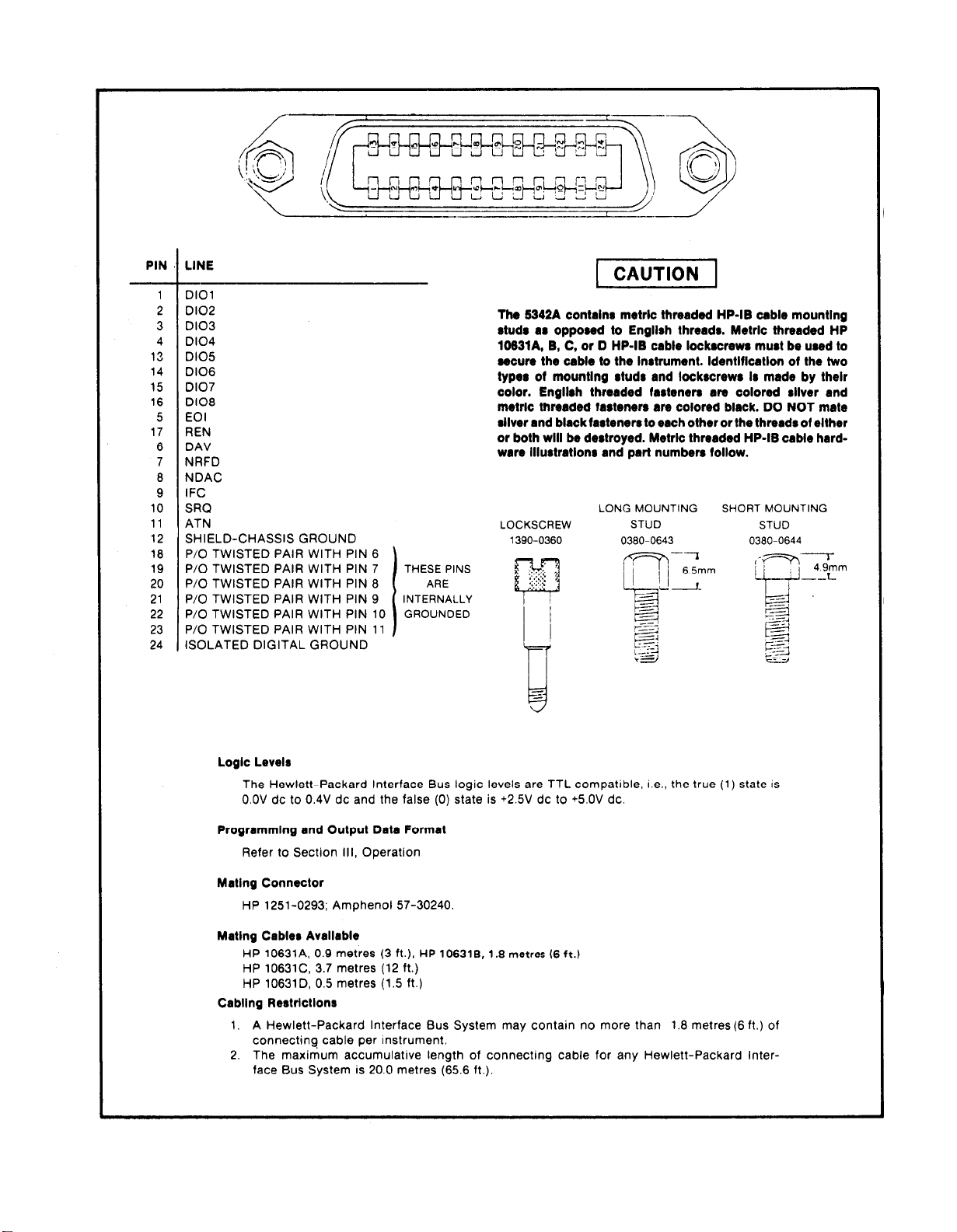
Model 5342A
Installation
2-10
Figure 2-3. Hewlett-Packard Interface Bus Connection
Page 29

Model 5342A
Operation
SECTION Ill
OPERATION
3-1. INTRODUCTION
3-2. This section contains operating information including operating characteristics, descrip-
tions of controls and indicators, and operating procedures.
3-3. OPERATING CHARACTERISTICS
3-4. The following paragraphs describe the operating ranges and modes, resolution, sample
rate, AM and FM characteristics, and auto-amplitude discrimination. Front panel controls and
indicators are described in Figure 3-1, rear paneI controls and connectors are described in Fig-
ure 3-2. Operating procedures are explained in Figure 3-3. Amplitude measurements (Option
002) are described in Figure 3-4. DAC operation (Option 004) is described in Figure 3-5.
3-5. Operating Ranges
3-6. There are two basic operating ranges: 10 Hz to 500 MHz and 500 MHz to 18 GHz.
Frequencies in the lower range are measured directly while measurements in the 500 MHz to
18 GHz range are made indirectly by a harmonic heterodyne down-conversion technique.
Provision is made to select either range by a front-panel slide switch. A separate input connector
is provided for each range. When the range switch is in the 10 Hz—500MHz position, the signal at
the BNC connector is routed to the direct count circuits of the 5342A. In this range, input impedance is selectable via the
range, the input signal is applied via the front-panel type N connector to the down-conversion
circuits of the 5342A.
50Ω−1 ΜΩ switch. When the range switch is in the 500 MHz—18 GHz
3-7. Resolution Keys
3-8. The best case resolution is the value represented by the least significant digit (LSD) in the
display. In the 5342A, a maximum resolution of 1 Hz can be selected (by the pushbutton keys on
the front panel labeled in blue, preceded by the blue key being pressed). The display is divided
into four sections for ease of determining GHz,MHz,kHz,and Hz resolution. Half-sized
used as space fillers within a section to improve interpretation of the display. For example, a
signal measured to 100 kHz resolution will be displayed thus:
3-9. The pushbutton keys on the front panel under the RESOLUTION label are used for other
purposes when the blue key is not in effect (has not been pressed). When the blue key has not
been pressed, the keys are defined by the black number on the keys and are used to enter fre-
quency offsets, manual center frequencies, and amplitude offsets as described in Figure 3-1.
3-1
Page 30

Model 5342A
Operation
3-10. CHECK, DAC, and ENTER keys
3-11. The CHECK, DAC, and ENTER keys are used as described in Figure 3-1.
3-12. FREQ Keys
3-13. Two of the pushbutton keys on the front paneI under the FREQ label are used to select the
automatic or manual mode of operation. The other keys in this section of the keyboard control
the use of the RESOLUTON keys. Use of these keys is described in detail in Figure 3-1.
3-14. Automatic Mode
3-15. The automatic mode of operation is selected by pressing the AUTO key. Input signals in
the 500 MHz—18 GHz range are acquired, measured, and displayed automatically. When power
is initially turned on, the 5342A goes into this mode automatically.
3-16. Manual Mode
3-17. The manual mode of operation is selected by pressing the MAN (MHz) key. To operate in
this mode, input signals in the 500 MHz-18 GHz range must be known to within 50 MHz and this
frequency (called the manual center frequency) must be entered into the display prior to the
measurement. Use of the manual mode is described in detail in Figure 3-3.
3-18. Offset Frequencies
3-19. It is sometimes desirable to add or subtract a constant to\from a frequency measurement.
For example, by measuring a radio IF and knowing the LO, the counter can display the RF input
when the LO frequency is entered as a positive offset. It may be easier to tune an oscillator to a
specific frequency if the desired frequency is entered as a negative offset and the oscillator tuned
until the counter reads zero. Frequency offsets are described in Figure 3-3.
3-20. Amplitude and Offset Measurements
3-21. When Amplitude Option 002 is installed, the amplitude is displayed in addition to the fre-
quency of the input signal. The frequency is displayed to 1 MHz resolution in the five leftmost
digits and the amplitude is displayed to 0.1 dB resolution in the four rightmost digits of the display. An arbitrary value can be selected as an amplitude offset and can be added to or subtracted
from the measured value as described in Figure 3-4.
3-22. Digital-to-Analog Converter (DAC) Operation
3-23. When DAC Option 004 is installed, any three consecutive digits of the display can be
selected and converted to a corresponding analog voltage output. The voltage is available at the
BNC connector on the rear panel (labeled DAC OUT) and is between
example, if the selected digits are
output is 9.99 volts dc. Operating procedures are listed in Figure 3-5.
3-24. SET, RESET, RECALL, and CHS Keys
∅∅∅ the output is ∅ volts and if the selected digits are 999 the
∅ and 9.99 volts dc. For
3-2
3-25. The SET, RESET, RECALL, and CHS keys allow offsets and center frequencies to be entered,
reset the measurement process, recall previous values, and change the sign of offsets as
described in Figure 3-3.
3-26. SAMPLE RATE, GATE, and REMOTE
3-27. The SAMPLE RATE control adjusts the deadtime between the end of one measurement
and the start of the next measurement. The duration of the measurement is determined by the
Page 31

Model 5342A
resolution selected. The SAMPLE RATE is variable between <20 ns and HOLD. In HOLD position
the display will hold the measurement displayed indefinitely.
3-28. The GATE indicator is lit during the measurement interval (gate time) when the counter’s
gate is open and accumulating counts.
Operation
3-29. The REMOTE indicator
3-30.
AM Tolerance
3-31. The 5342A will measure carrier frequencies containing amplitude
modulation index provided the minimum voltage of the signal is not less
specification of the 5342A.
3-32.
FM Tolerance
3-33. The 5342A will measure carrier frequencies which are modulated in frequency such as a
microwave radio carrier. The FM tolerance is the worst case FM deviation which can be present
without affecting the counters ability to acquire the signal. If the deviations about the carrier are
symmetrical, then the counter averages out the deviations to measure the actual carrier frequency. The FM tolerance is determined by the position of the CW-FM switch on the rear panel.
The CW position provides FM tolerance of 20 MHz peak-to-peak. The FM position provides a
tolerance of 50 MHz peak-to-peak but results in slower acquisition time (2.4 seconds compared
to 530 milliseconds for CW position).
is lit when the 5342A is in remote operation (Option 011 installed).
modulation to any
than the sensitivity
NOTE
Most measurements should be made with the rear
panel FM/CW switch in CW position. The FM
position should be used only when the input signal
has significant amounts of FM (>20 MHz p-p). In-
correct measurements may result if the FM position is
used with a stable input (non-FM) signal which has
been locked to the counter’s time base.
3-34. Automatic Amplitude Discrimination
3-35. The automatic amplitude discrimination feature allows the 5342A to acquire and display
the highest level signal within its sensitivity range. The highest level signal must be 20 dB greater
in amplitude than any other signal present. Typical operation is approximately 10 dB. This feature
is useful for discriminating against spurious signals and harmonics.
3-36. MAXIMUM INPUT SIGNAL POWER
CAUTION
Do not exceed
N
type
connector
+25
dBm (peak) of input power at the
(500 MHz–18
GHz). Damage to the
internal sampler may occur. Refer to paragraph 3-37
for detailed explanation.
3-37. The 5342A will function within specifications for 500 MHz-18 GHz signal inputs up to
+5 dBm (standard unit). For measuring higher level inputs, refer to the options described in para-
graphs 3-61 and 3-63. Under no circumstances should the input level to the 5342A exceed
+25 dBm. If the input power exceeds this Ievel, damage to the internal sampler may occur and the
sampler is expensive to replace. Measurements from +5 to +25 dBm are not recommended as
false readings may occur. When signal levels exceed +5 dBm external attenuators should be used
to attenuate the signal. Options 002 and 003 can extend the range to +20 dBm.
3-3
Page 32

Model 5342A
Operation
3-38. The 10 Hz—500 MHz direct count input BNC connector is fuse-protected for a maximum
input level of 3.5V rms (+24 dBm).
3-39.
3-40. Consideration should be given to input cable losses at higher frequencies. For example, a
6-foot section of RG-214/U coaxial cable has about 15 dB loss at 18 GHz. Such losses must be
taken into consideration along with the sensitivity specifications given in Table 1-1.
3-41. CONTROLS, INDICATORS, AND CONNECTORS
3-42. Figure 3-1 describes the front panel controls, indicators, and connectors. Figure 3-2
describes the rear panel connectors and controls.
INPUT CABLE CONSIDERATIONS
WARNING
BEFORE THE INSTRUMENT IS SWITCHED ON, ALL
PROTECTIVE EARTH TERMINALS, EXTENSION
CORDS, AUTOTRANSFORMERS
CONNECTED TO IT SHOULD BE CONNECTED TO A
PROTECTIVE EARTH GROUNDED SOCKET. ANY
INTERRUPTION OF THE PROTECTIVE EARTH
GROUNDING WILL CAUSE A POTENTIAL SHOCK
HAZARD THAT COULD RESULT IN PERSONAL
INJURY.
AND DEVICES
ONLY FUSES WITH THE REQUIRED RATED CUR-
RENT AND SPECIFIED TYPE SHOULD BE USED. DO
NOT USE REPAIRED FUSES OR SHORT CIRCUITED
FUSEHOLDERS. TO DO SO COULD CAUSE A SHOCK
OR FIRE HAZARD.
CAUTION
Before the instrument is switched on, it must be set to
the voltage of the power source, or damage to the
instrument may result. (Refer to paragraph 2-6.)
3-43.
OPERATING PROCEDURES
3-44. Figure 3-3 illustrates operating procedures for the standard 5342A. Self-check procedures
are also given in Figure 3-3. An operators keyboard check is given in paragraph 3-45. Operating
procedures for Amplitude Option 002 are listed in Figure 3-4,
Figure 3-5.
and for DAC Option 004 in
3-4
Page 33

Model 5342A
Operation
DISPLAY
Digits:
The display contains 11 digit positions, two digits for frequencies in GHz and three digits each for
MHz, kHz, and Hz. (The Hz digits position is used to display dBm when Amplitude Option 002 is
installed.)
Annunciators:
-Sign
OVN indicator Oven monitor indicates when crystal oscillator oven is on (warming). When
warmed-up, light goes out (Option 001 only).
dBm indicator
002 installed). pressing AMPL key and displayed in Hz portion of display. The fourth
digit from the right displays a — sign for signals below 0 dBm.
* indicator
the wide-band mode which provides wider FM (50 MHz p-p) tolerance.
FREQ Keys
The FREQ keys select the mode of operation and control the display.
When lighted, indicates a negative frequency offset has been entered into display (MHz).
lighted, indicates amplitude of input signal is being measured (Option
When lighted, indicates the rear panel CW-FM switch is in FM position. This selects
NOTE
Some keys are equipped with center indicator lights that serve as
“prompters” to the user. A blinking indicator light states a “ready”
condition for the key function that was selected and the instrument is
waiting for a mode or number to be entered. A steady indicator light
states that the key function that was selected is in operation.
AUTO key. Selects the automatic mode of operation to acquire and display input signal frequencies
in the 500 MHz-18 GHz range. The instrument goes into this mode when power is turned on.
MAN (MHz) key. Selects manual mode for input signal frequencies in the 500 MHz—18 GHz range.
Input signal frequency must be known (within 50 MHz) and entered into display via the blacknumbered keys.
Figure 3-1. Front Panel Controls and Indicators
3-5
Page 34

Model 5342A
Operation
AMPL key. Selects amplitude mode (when Option 002 is installed). The amplitude of the input signal
is displayed in the four rightmost digits of the display to a resolution of 0.1 dBm. The frequency
of the input signal is displayed in the five leftmost digits of the display.
OFS dB key. After pressing the SET key, the OFS dB key is pressed prior to entering an offset value
in dB via the digit keys. (Digit keys are labeled in black numbers under RESOLUTION.) Indicates
selection of amplitude offset mode when lighted and adds amplitude offset to measured amplitude
(Option 002).
OFS MHz key. After pressing the SET key, the OFS MHz key is pressed prior to entering an offset
value via the digit keys. (Digit keys are labeled in black numbers under RESOLUTION.) Indicates
selection of frequency offset mode when lighted and adds frequency offset to measured frequency.
RESOLUTION keys:
The resolution keys select the display resolution (according to the blue labeling above each key)
after the blue key is pressed. The keys are defined by the black number labeled on the key when
entering offsets and manual center frequencies.
Blue key. Pressing this key activates the blue-labeled functions of the RESOLUTION keys.
RESET key. Clears the display and restarts a measurement. Clears any blinking lights in key center
indicators.
SET key. Must be pressed prior to selecting OFS dB, OFS MHz or MAN (MHz). The SET condition
is indicated by lighted segments in the GHz digits of the display. This indicates that a center
frequency, offset frequency, or amplitude offset may be entered into the display.
RECALL key. Recalls stored memory information into display. The MAN (MHz), OFS dB, or OFS
MHz keys, if held in after RECALL is pressed, will result in a display of previously entered or computed information.
NOTE
Information stored in memory (by digit keys) after MAN (MHz) key is
pressed is available for display until AUTO mode is selected. Then the
center frequency determined by the automatic measurement overrides
the manual information.
NOTE
An offset value is an arbitrary value selected for entry into the display
to be added or subtracted from a measured value.
CHECK key. After pressing the blue key, the CHECK key is pressed to perform a self-check of the
instrument. The display will indicate 75 MHz for proper operation. Press RESET to exit self-check.
NOTE
The instrument must not have an input signal connected at the
500 MHz-18 GHz input to perform the self-check.
3-6
ENTER key. Used to enter digits for manual center frequencies or offsets into memory via blacknumbered keys. After the digits have been selected, ENTER key is pressed to signal the end of the
digit sequence.
LINE switch. In ON position, applies power to all circuits except the crystal oven (Option 001 installed). The crystal oven connects through a separate transformer, a thermal circuit breaker and
fuse directly to the ac line. This allows the oven to maintain its operating temperature and accuracy
when the LINE switch is in STBY position, thereby eliminating warmup delays.
SAMPLE RATE control. Adjusts the interval between measurements from 20 ms to HOLD. When
rotated to HOLD will hold display indefinitely.
GATE indicator. Indicates when counters main gate is open and a measurement is in progress.
REMOTE indicator. Illuminates when counter is in remote operation.
50Ω−1 ΜΩ switch. Selects input impedance for adjacent 10 Hz-500 MHz input connector.
10 Hz-500 MHz, 500 MHz-18 GHz switch. Selects either low or high frequency range input
connector.
BNC Input Connector. Accepts 10 Hz-500 MHz input for direct count measurements. Measurements
made at this input require that the range switch is set to the 10 Hz-500 MHz position. Sensitivity is
listed in Table 1-1.
Type N Input Connector. Input for measurements in the 500 MHz-18 GHz range. Measurements
made at this input require that the range switch is set to the 500 MHz-18 GHz position. Sensitivity
is listed in Table 1-1.
Figure 3-1. Front Panel Controls and Indicators (Continued)
Page 35

Model 5342A
Operation
1.
PROCESSOR INTERFACE connector A22W4JI. Not used. This connector is part of cable W4
which is connected to A22 motherboard as an interface to the A14 Microprocessor address and
data lines. This interface is provided for future use with companion instruments.
2.
position of digital input/output connector when instrument is equipped with Hewlett-Packard
Interface Bus (HP-1B) Option 011. Refer to paragraph 3-69 for details.
3.
Position of ADDRESS switch when instrument is equipped with Hewlett-Packard Interface
Bus (HP-IB) Option 011. Refer to paragraph 3-72 for details.
4.
AC Power Module. Input power module consisting of an IEC approved connector, a fuse
(0.75 amp for 100/200-volt operation, 0.375 for 220/240-volt operation) and a p
voltage selector. Refer to paragraph 2-6 for details.
5.
CW-FM selector switch. Selects a short or long pseudorandom sequence (prs). The CW
position provides a short prs (or narrow mode) with FM tolerance of 20 MHz p-p. The FM
position provides a long prs (or wide mode) with FM tolerance of 50 MHz p-p.
NOTE
Most measurements should be made with the rear panel FM/CW
switch in the CW position. The FM position should be used only when
the input signal has significant amounts of FM (>20 MHz p-p).
lNT/EXT selector switch. Selects the internal 10 MHz crystal oscillator signal or an external
6.
10 MHz source for the time base circuit. The external source must be connected to the adjacent
connector (7).
NOTE
[f the lNT/EXT switch is switched and causes momentary loss of
clock, the microprocessor may hang up and cause the display to stop
counting. To recover, press LINE switch to STBY then to ON.
7.
EXT FREQ STD connector. Accepts 10 MHz external time base signal when INT/EXT switch
is in EXT position.
8.
FREQ STD OUT connector. Supplies a 10 MHz squarewave output at 1.5 volts peak-to-peak.
IF OUT connector. provides the intermediate frequency (IF) output of the Preamplifier circuit
9.
for test or monitor of the IF.
10.
DAC connector. Provides the output voltage of the digital to analog converter when the
Option 004 is installed.
C card line
Figure 3-2. Rear Panel Controls and Connectors
3-7
Page 36

Model 5342A
Operation
PRELIMINARY PROCEDURES
1. On rear panel:
a. Set lNT/EXT to INT position.
b. Set CW/FM switch to CW. Refer to paragraph 3-33 for detailed description.
c. On ac power module, check for proper fuse (0.75 amp for 100/120-volt operation, 0.375
amp for 220/240-voh operation) and check position of pc line voltage selector (refer to
paragraph 2-6 for detailed description).
d. For remote operation, refer to paragraph 3-69 for explanation of HP-IB programming and
address switch settings on rear panel (for 5342A’s equipped with Option 011).
2. On front panel, set LINE switch to ON position.
Do not exceed +25 dBm peak of input power at the type N connector (500 MHz-18 GHz). Damage to the internal sampler may
occur.
NOTE
When the input signal level to the type N connector exceeds
approximately +5 dBm, each digit in the display becomes a minus
sign (-) to indicate overload. For Options 002,003, this threshold is
approximately +20 dBm.
The 10 Hz-500 MHz direct count input BNC connector is fuseprotected for a maximum input level of 3.5V rms (+24 dBm).
NOTE
The fuse for the 10 Hz-500 MHz input is located on the A3 Direct
Count Amplifier assembly.
3-8
Figure 3-3. Operating Procedures
Page 37

3.
Connect input signal to appropriate input connector according to frequency requirements
(BNC for 10-500 MHz, type N for 500 MHz-18 GHz) and set frequency range switch
accordingly.
4.
For input signals connected to BNC connector (10-500 MHz): set the 50Q-1 MQ switch as
required. This switch has no effect on input signals connected to the type N connector (500
MHz-18 GHz).
Press blue key, then press blue-labeled RESOLUTION key for desired resolution.
5.
NOTE
Half-sized are used as fillers in the display to facilitate display
interpretation.
Adjust SAMPLE RATE control for desired interval between measurements.
6.
KEY INDICATORS
Indicator LED’s in the center of some keys are used as “prompters”
by the operator, as follows:
Blinking Indicator
A blinking LED in a key is a “ready” condition for that key function.
It indicates it is waiting for an entry via the keyboard. To clear the con-
dition, press RESET.
Steady Indicator
A steady “on” LED in a key is an indication that the key function is in
effect. To clear the condition, press the key. (The AUTO Key is cleared
by pressing MAN (MHz) and vice versa.)
Model 5342A
Operation
SELF-CHECK PROCEDURE
Perform the self-check as follows (no input signal connected and
SAMPLE RATE full
CCW):
The manual center frequency is entered (and displayed) with 1 MHz
resolution and must be within so MHz of the input signal frequency
(connected to 500 MHz—18 GHz connector).
Figure 3-3. Operating Procedures (Continued)
3-9
Page 38

Model 5342A
Operation
3-10
Figure 3-3. Operating Procedures (Continued)
Page 39

AUTOMATIC OFFSETS
Example
subsequent measurements:
- To “hold” a measurement and use it as a negative offset in
Rotate SAMPLE RATE cw to HOLD
Rotate SAMPLE RATE ccw to normal
NOTE
The measured frequency will now be negatively offset by the frequency
captured when in HOLD.
Model 5342A
Operation
RESET
RESET
Pressing key clears the display and initiates a new measurement
without clearing stored values of offset or center frequencies. Clears
any blinking (ready state) key indicators, but does not clear steady
state indicators. 5342A maintains current operating modes.
Figure 3-3. Operating Procedures (Continued)
3-11
Page 40

Model 5342A
Operation
3-12
Figure 3-4. Amplitude Measurements (Option 002)
Page 41

Model 5342A
Operation
Figure 3-5. DAC Operation (Option 004)
3-13
Page 42

Model 5342A
Operation
3-45.
3-14
Page 43

Model 5342A
Operation
3-15
Page 44

Model 5342A
Operation
3-47. ERROR CODE DISPLAYS
3-48. Error codes are displayed by the 5342A to indicate circuit malfunctions in the instrument
and to indicate operator (procedure) errors.
3-49. Instrument Error Displays
3-50. When power is applied to the 5342A, check-sum routines are automatically performed. if
a routine fails, an error code is displayed to indicate the circuit fault area as follows:
3-16
NOTE
If any of the above codes are displayed. refer to the
troubleshooting procedures in Table 8-5.
Page 45

3-51.
Operator Error Displays
3-52.
Model 5342A
Operation
3-17
Page 46

Model 5342A
Operation
3-53.
3-54.
displayed as:
3-55. A sequence error (for example, pressing a digit key before pressing a function key) will be
displayed as:
3-56. For detailed descriptions of error codes, refer to Table 8-5.
3-57. OPTIONS
Limit Errors and Sequence Errors
A limit error (for example, setting a manual center frequency less than 500 MHz) will be
.
3-58, The operating characteristics of the 5342A are affected by the addition of any of the
options described in the following paragraphs.
3-59. Time Base Option 001
Option 001 provides an oven-controlled crystal oscillator time base (Model 10544A) that
3-60.
results in higher accuracy and longer periods between calibration (refer to Table 1-1). The oven
temperature is maintained when the 5342A LINE switch is in either the ON or the STBY position
(provided the instrument is connected to the power mains). When the OVN indicator in the
display is lit, the oven is on (warming). When the oven is at the proper temperature, the OVN
indicator goes out.
3-61. Amplitude Option 002
3-62. The amplitude option provides the capability of measuring the amplitude of the input
signal and simultaneously displaying the frequency (5 leftmost digits) and the amplitude level in
dBm (4 rightmost digits). The maximum operating level of +5 dBm for the standard 5342A is
extended to +20 dBm for Option 002. The frequency is displayed to a resolution of 1 MHz and the
level is displayed to a resolution of 0.1 dBm, The sensitivity of the 5342A with Option 002 is
approximately 3 to 5 dB less than the standard 5342A, depending upon frequency.
3-63.
Extended Dynamic Range Option 003
3-64. The extended dynamic range option extends the maximum operating level of + 5 dBm for
the standard 5342A to +20 dBm for Option 003 by insertion of an attenuator at the input (ahead of
the sampler), The insertion loss of the attenuator results in a sensitivity decrease of approximately
3 to 5 dB, depending upon the frequency of the signal.
-
.
3-65.
HP-IB Interface Option 011
3-66. The Hewlett-Packard Interface Bus (HP-IB) Option 011 allows the functions of the 5342A
to be controlled remotely and allows measurement data to be ouptut to the bus, Programm-
ing information for Option 011 is given in paragraphs 3-69 through 3-80.
3-18
Page 47

Model 5342A
Operation
3-67. Digital-to-Analog Converter (DAC) Option 004
3-68. The DAC option allows selection of any three consecutive digits in the display and con-
version of these digits to an analog voltage. The analog voltage is available at a rear panel con-
nector. The digits are converted to a voltage of from 0 to 10 volts, corresponding to the digits
selected. Digits 000 produce 0 volts, digits 999 produce 9,99 volts, fullscale into 15 kilohms.
3-69. HP-IB PROGRAMMING (OPTION 011)
3-70. The capability of a device connected to the HP-IB is specified by its interface functions.
Table 3-1 lists the interface functions of the 5342A using the terminology of IEEE Standard
488-1975 (Appendix C). Interface functions provide the means for a device to receive, process,
and send messages over the HP-19, Procedures for verification of proper operation of Option 011
HP-IB are contained in paragraphs 4-19 through 4-26.
Interface Function
Subset Identifier
SH1
AH1
T1
L2
SRI
RL1
PP0
DCI
DT1
C0
E1
Table 3-1. HP-/B Interface Capabilitv
Interface Function Description
Complete source handshake capability.
Complete acceptor handshake capability.
Talker (basic talker, serial poll, talk only mode, does not unaddress to talk if
addressed to listen).
Listener (basic listener, no listen only mode, doe not unaddress to listen if
addressed to talk),
Service request capability.
Complete remote/local capability.
No parallel poll capability.
Device clear capability.
Device Trigger capability.
No controller capability.
One unit load.
.
3-71. There are 12 basic messages which can be sent over the interface. Table 3-2 lists each bus
message, a description of the message, how the 5342A uses that message, and examples of 9825A
implementation of the messages.
3-72. The 5342A must be assigned a bus address. Table 3-3 gives the allowable address switch
settings.
3-73. Table 3-4 gives the program code set for the 5342A, Frequency and amplitude mode ,
selection, manual center frequency setting, frequency and amplitude offset mode selection, frequency and amplitude offset setting, resolution selection, range selection, FM/CW mode selection, and automatic offsets are all analogous to the corresponding front panel operations
described previously.
3-74. There are four sample rate modes T0-T3. In T0, the sample rate is determined by the
setting of the front panel SAMPLE RATE control, In T1, the counter is in hold. To trigger a measurement, a trigger message must be sent. In T2, the counter ignores any sample rate run-down
and initiates a new measurement as soon as the previous measurement is over. In T3, the counter
takes a measurement and holds until the next T3 or trigger message.
3-19
Page 48

Model 5342A
Operation
Message
Data
Trigger
Clear
Remote
Local
Local
Lockout
Clear
Lockout
and local
Require
Service
Status
Status Bit A single bit of device-dependent
Control
Abort
Byte
Pass
Table 3-2. 5342A Bus Message Usage
Description
Transfers device-dependent
information from one device to
one or more devices on the bus.
Causes a group of selected
devices to simultaneously
initiate a set of devicedependent actions
Causes an instrument to be set to
a predefined state (a certain
range, function, etc.).
Permits selected devices to be
set to remote operation, allowing parameters and device characteristics to be controlled by
Bus Messages.
Causes selected devices to return to local (front panel)
operation.
controls of selected devices.
Returns all devices to local (front
panel) control and simultaneously clears the Local Lockout
Message,
Indicates a device’s need for
interaction with the controller.
Presents status information of a
particular device; one bit indicates whether or not the device
currently requires service, the
other 7 bits (optional) are
used to indicate the type of
service required.
status information which may be
logically combined with status
bit information from other devices by the controller.
Passes bus controller responsibilities from the current controller to a device which can
assume the Bus supervisory role.
Unconditionally terminates Bus
communications and returns
control to the system controller.
5342A Use
Sends measurement data. See
paragraph 3-77 for output
format. Accepts program codes.
See Table 3-4 for code set.
Starts a new measurement.
Same as front panel RESET.
Clears internal count and starts
new measurement.
5342A goes to remote if REN is
true and addressed to listen. In
absence of program data, re-
mote operation is according to
the state of the front panel settings just prior to going to
remote.
Goes to local front panel con-
trol. In absence of front panel
data, local operation is accord-
ing to the state of the remote
data just prior to going to local.
Disables front panel RESET.Disables local (front panel)
5342A remains in remote.
Local lockout cleared and returns to local front panel control
Pulls on SRQ to indicate end of a
measurement.
In serial poll mode, 5342A out-
puts decimal 80 (01010000) to
indicate end of measurement,
Does not use
Does not use
Clears Talk, Listen, Serial Poll
Enable registers on 5342A HP-IB
interface. Front panel annunci-
ators do not change, however,
Sample 9825 Statements
(5342A set to Address 02)
red 702, A
wrt 702, “AUSR4”
trg 7 or
trg 702
clr 7 or
clr 702
702
rem
IcI 702
llo7
Icl 7
rds(7)-A
if bit (7, A)
7=1 if SRQ true)
(bit
rds (702)-A
(if A=80, then 5342A is
ready to output)
cli 7
3-20
Page 49

Table 3-3. Address Selection
Model 5342A
Operation
3-21
Page 50

Model 5342A
Operation
Table 3-4. Option 011 HP-IB Program Code Set
3-22
Page 51

Table 3-4. Option 011 HP-IR Program Code Set (Continued)
Model 5342A
Operation
3-75. ln the“output only when addressed” mode, the counter pulls SRQ at the end of a measurement and then checks to see if it has been addressed to talk, If not, SRQ is cleared and it starts
the next measurement.
and-starts the next measurement.
at the end of a measurement and waits in a loop until it has been addressed to talk. When it is
SRQ
If it has been addressed to talk, it outputs the measurement, clears SRQ,
In the “wait until addressed” output mode, the counter pulls
addressed to talk, it outputs the measurement, clear SRQ and starts the next measurement,
NOTE
[f the counter is placed in the HOLD (T1) mode,
triggered, then addressed to talk, be sure to use the
Wait Until Addressed (ST2) output mode. If not, then
for short gate times the measurement may be completed before the controller addresses the counter to
talk and the counter will discard the measurement
result and hang up the bus.
3-76. The 5342A executes each complete program code as it is received just as if the microprocessor were receiving the data from the front panel keyboard, Program code strings should
be in the same order as they would be if being entered from the front panel. When a data byte is
sent to the 5342A HP-IB Option 011, the HP-IB interface stores the byte and sends an interrupt to
the microprocessor which reads in the byte. If the byte does not complete a program code, then
the microprocessor waits for the next byte(s) until a complete code is sent (for example, SR5 is a
complete code but SR is not). After a complete code is received, the microprocessor executes the
code and begins the measurement. If more codes are in the string, another interrupt is generated. For example, if the string “SR5AU” is sent by the controller, the “S” is the first byte received
and stored by the 5342A HP-IB interface. The interface generates an interrupt to the microprocessor and the “S” is read by the MPU. Since S is not a complete code, the microprocessor
3-23
Page 52

Model 5342A
Operation
waits until the complete code is sent and received. After “R” and then “5” are sent, the micro-
processor sets the resolution accordingly and then goes to the beginning of the measurement.
When the controller sends “A”, an interrupt is generated and “A” is read by the microprocessor.
It then waits for the complete code to be sent which in this case is “AU”. The microprocessor
again goes to the start of the measurement cycle.
3-77.
Table 1-1.
paragraph 3-82.
3-24
3-78.
Page 53

3-79. 9825A PROGRAM EXAMPLES
3-80. The following 9825A program examples are illustrative of 5342A programming:
EXAMPLE 1
This program assumes the range switch was set to 0.5-18 GHz
before the program was executed. The program puts the
5342A in AUTO, 10 kHz resolution, HOLD, and “wait until
addressed” output mode. Program takes a measurement
(trg 702) and reads it into the A register. After waiting 500 ms,
the program loops back to the next trigger, then read
statement.
Model 5342A
Operation
EXAMPLE 2
This program also assumes the range switch was previously
set to the 0.5-18 GHz position. The program puts the counter
in AUTO mode, 10 Hz resolution, fast sample, and “only if
addressed” output mode. The program takes a measurement,
unaddressed the 5342A as a talker (cmd 7, “-”) so that the
counter will continue making measurements at a fast rate,
and waits 500 ms until reading the next measurement.
EXAMPLE 3
This program sets a manual center frequency of 10 GHz
(input frequency
range, FM mode, front panel sample rate control, and “output only if addressed”. Each reading is printed on the 9825A
printer.
= 10.03 GHz), 1 Hz resolution, 0.5-18 GHz
3-25
Page 54

Model 5342A
Operation
EXAMPLE 4
This program selects AUTO mode, 1 Hz resolution, fast
sample, “output only if addressed”, and amplitude “on”. The
frequency is read into the A register and-the amplitude is
read into the B register. Notice that although the frequency
is displayed only to 1 MHz resolution on the counter, the full
1 Hz resolution is output to the calculator.
EXAMPLE 5
This program measures the same signal as in (4) but enters
a -10 dB offset in the amplitude measurement.
3-26
Page 55

Model 5342A
EXAMPLE 6
This is the same program as (5) but with a +10 GHz offset.
Operation
3-27
Page 56

Model 5342A
operation
3-81.
3-82.
a.
b.
c.
d.
HP-IB
The HP-IB output is affected by input signal level as follows:
For input signal levels greater than or equal to specified sensitivity, the 5342A outputs
measurement data as described in paragraph 3-77.
For input signal levels less than the actual sensitivity by 0.1 dB or more (or for no input),
the counter outputs zeros when addressed to talk.
For input signal levels just on the edge of the ccunter’s actual sensitivity (approximately a ,
0.1 dB band) the detectors which indicate sufficient signal level for counting may become
intermittent resulting in very long acquisition times. The counter’s display holds the
previous reading during the prolonged acquisition but the counter will not output any
data when addressed to talk. This will hang up the program at the read statement.
With the 9825A, use the “time” statement and “on err” statement to branch around the
read statement if it takes longer than a specified number of milliseconds to complete an
1/0 operation. The following example program can be used when there is more than one .
read statement in the program. If there is only one read statement, then statement 2
could be deleted and the end of statement 7 could simply cause the program to go to the
statement after the read (in this case, “gto 6“):
PROGRAMMING NOTES
Since this statement is in line 2, the
program jumps to the statement after
the read statement.
3-28
Error 4 is time out error. Reset time
and error jump.
When the 5342A took more time than
1 second to make the measurement,
zeroes are output.
Page 57

NOTE
For any controller, check SRQ to see if a measurement has been completed.
number of iterations on the SRC) check to permit the
counter to complete the measurement and pull SRQ.
A flow diagram of such an algorithm is:
Allow an adequate
Model 5342A
Operation
3-29
Page 58

Model 5342A
Operation
3-83. REMOTE PROGRAMMING OF DIAGNOSTIC MODE 6
(OPTION 002,011 ONLY)
3-84. In some system applications, it may be desirable to program the 5342A to diagnostic mode
6 so that the counter will constantly present a low SWR and not switch to frequency measure-
ments (higher
SWR). The following example shows how this may be done:
EXAMPLE
— Program counter for AMPL mode
.
This sets the counter to diagnostic mode 6
Counter must be triggered to enter
‘diagnostic mode 6. For 5 seconds,
counter does not switch to frequency.
This resets the counter to amplitude and
frequency measurements
3-30
Page 59

Model 5342A
Performance Tests
SECTION IV
PERFORMANCE TESTS
4-1. INTRODUCTION
4-2. The procedures in this section test the electrical performance of the 5342A using the specifications in Table 1-1 as performance standards. Those specifications which are inherent to the
design (obvious during operation) are not covered in these tests. For example, worst case acquisition time is determined by the period of the sweep and the length of the pseudo-random
sequence. If the counter acquires the signal, it must have acquired it in a time less than specified.
4-3. OPERATIONAL VERIFICATION
4-4. The abbreviated checks given in paragraphs 4-12 through 4-18 can be performed to give a
high degree of confidence that the 5342A is operating properly without performing the complete
performance test. The operational verification should be useful for incoming QA, routine
maintenance, and after instrument repair. The Option 011 HP-IB Verification Program is
described in paragraphs 4-19 through 4-26. The Option 004 DAC test is contained in paragraph 4-27.
4-5. COMPLETE PERFORMANCE TEST
4-6. The complete performance test is given in paragraphs 4-28 through 4-40. All tests can be
performed without access to the inside of the instrument.
4-7. EQUIPMENT REQUIRED
4-8. Equipment required for the complete test and operation verification is listed in Table 1-4.
Any equipment which satisfies the critical specifications given in the table may be substituted for
the recommended model numbers.
4-9. TEST RECORD
4-10. Results of the operational verification may be tabulated on the Operational Verification
Record, Table 4-1. Results of the performance test may be tabulated on the Performance Test
Record,
Table 4-5.
4-1
Page 60

Model 5342A
Performance Tests
4-11.
4-12.
4-13.
Instruments Only)
OPERATIONAL VERIFICATION
Self-Check
a.,
Select 1 Hz resolution, AUTO mode, and 500 MHz—18 GHz range. Set self-check mode
and verify counter displays 75.000000 MHz ±1 count.
Set 5342A to 10 Hz—500 MHz range. Connect rear panel FREQ STD OUTPUT to front
b.
panel BNC input. Select 50 impedance. Verify that the 5342A counts 10.000000 MHz ±1
count.
10 Hz-500 MHz Input Sensitivity Test, /1 (Standard and Option 003
Setup:
PROCEDURES
-
Set the 5342A to 10 Hz—500 MHz range and 500.
Set 8620C to 10 MHz and a level of -19.3dBm (25 mV rms) as measured on
the 436A Power Meter. Measure actual sensitivity and verify that the
5342A counts at 10 MHz, 100 MHz, 520 MHz, and record on operational
verification record (Table 4-1).
Disconnect 11667A and connect 8481A directly to 86222A output. Set
8620C to 25 MHz at a level of -19.3 dBm (25 mV rms).
Disconnect 8481A from 86222A output. Switch 5342A to the 1
position. Connect 86222A output to 5342A 10 Hz—500 MHz input
(86222A supplies 25 mV rms into
Verify that the 5342A counts 25 MHz at 50 mV rms and record on operational verification record (Table 4-1).
50fl
or 50 mV rms into 1
Mfl).
Mfl
.
.
4-2
Page 61

Model 5342A
Performance Tests
4-14. 10 Hz-500
Specification:
Setup:
MHz Input (500) Minimum Level and Amplitude Accuracy Test (Option 002)
±1.5 dB accuracy for frequencies from 10 MHz to 520 MHz.
Minimum Level: -17 dBm.
●
Connect the 11667A directly (using type N to BNC adapter) to the 5342A
BNC low frequency input. Connect 8481A directly to the other 11667A
output.
●
Set the 5342A to 10 Hz-500 MHz range, 50Q, and amplitude mode.
●
Set the 86222A to 10 MHz and adjust output level and 8495B for a level of
-17 dBm as measured on the 436A Power Meter. (8495B set to 10 dB or
greater.) Slowly vary the 8620C from 10 Hz to 520 MHz and verify that the
5342A displays correct frequency.
●
Take a measurement at 10 MHz, 100 MHz, and 520 MHz, and verify that
5342A reading is within ±1.5 dB of 436A reading. Enter results on operational verification record (Table 4-1).
4-3
Page 62

Model 5342A
Performance Tests
4-15.
10 Hz-500 MHz Input (50Q) Maximum Input Test (Option 002)
Specification:
Setup:
+20 dBm
●
Set the 8495B to 10 dB,
●
Set the 3312A to 13 MHz sine wave with AMPLITUDE set to 10. Adjust
amplitude vernier for a +15 dBm output level (+5 dBm on 436A).
●
Set the 5342A to AMPL mode, 50Q, 10 Hz—500 MHz range and connect
the 3312A output to the 5342A input. Increase the 3312A output until
the 5342A measures +20 dBm.
●
Disconnect output of 3312A from 5342A and connect it to 8495B. Power
meter should display +10 dBm ±1.5dB (allowing for the + 10 dB of 8495 B).
Enter on operational verification record (Table
●
Reconnect 3312A to 5342A and increase power output until 5342A
4-1).
“dashes” the display to indicate overload. This must occur at a level
greater than +20 dBm. Enter on operational verification record.
4-4
Page 63

Model 5342A
Performance Tests
4-16. 500 MHz—18 GHz Input Sensitivity Test (Standard and Option 003 Instruments Only)
Specification:
Description:
Sensitivity = -25 dBm, 500 MHz-12.4 GHz
= -20 dBm, 12.4 GHz-18 GHz.
For Option 003:
Sensitivity = -22 dBm, 500 MHz-12.4 GHz
= -15 dBm, 12.4 GHz-18 GHz.
The 5342A is set to the 500 MHz-18 GHz range and a signal at the rated
sensitivity is applied to the type N connector. The frequency is slowly
varied over the range of 500 MHz to 12.4 GHz and the 5342A is checked
for proper counting. The output level of the test generator is increased to
the second value, the frequency is slowly varied from 12.4 GHz to 18
GHz, and the 5342A checked for proper counting.
●
Set the 5342A to the 500 MHz-18 GHz range.
●
Connect the 11667A Power Splitter directly to the 5342A type N connector. Connect the 8481A power sensor directly to the other output port of
the 11667A power splitter.
●
Set the 8620C with the appropriate plug-in (86222A for 500 MHz to 2 GHz,
86290A for 2 GHz-18 GHz) and the 8495B step attenuator to the rated
sensitivity as measured on the 436A. Remember that the 5342A with
Option 003 has different specifications.
●
Slowly increase the 8620C frequency over the range and verify that the
5342A counts properly.
●
Measure actual sensitivity at 1 GHz,12.4GHz, and 18GHz. Enter on operational verification record (Table 4-1).
4-5
Page 64

Model 5342A
Performance Tests
4-17. 500 MHz-18
Specification:
GHz Input Minimum Level and Amplitude Accuracy Test (Option
±1.5 dB accuracy for frequencies from 500 MHz to 18 GHz.
Minimum level:
-22 dBm 500 MHz-12.4 GHz
-15 dBm 12.4 GHz-18 GHz
Description: A signal at the minimum level is applied to the 5342A and 436A power
meter and is varied over the frequency range. The amplitude reading of
the 5342A is compared to the 436A Power Meter (calibration factor
included).
Setup:
002)
4-6
●
Connect the 11667A directly to the 5342A type N connector and connect
the 8481A directly to the other 11667A output.
●
Set the 8620C at 500 MHz and adjust the output level and the step
attenuator for -22 dBm as measured on the 436A Power Meter.
●
Set the 5342A to the 500 MHz-18 GHz range and select amplitude mode.
Slowly vary the 8620A up to 12.4 GHz and verify correct 5342A display.
●
Take measurements at 1 GHz and 12.4 GHz. Verify that the 436A reading
is within ±1.5 dB of the 5342A reading. (Be sure to change the 436A calibration factor with frequency.) Record difference between 436A and
5342A readings on verification record,
●
Set the 8620C to 12.4 GHz and adjust the output level to -15 dBm as
measured on the 436A Power Meter. Slowly vary the 8620C up to 18GHz
and verify correct 5342A display.
●
Take a measurement at 18 GHz and verify that the 5342A is within ±1.5 dB
of the 436A reading (be sure to adjust 436A calibration factor). Record
difference between 436A and 5342A readings on verification record
(Table
4-1).
Page 65

4-18. 500 MHz-18 GHz High Level Test
Model 5342A
Performance Tests
For Standard Instrument:
Set the 8620C to 1 GHz at +5.0 dBm as measured by the 436A Power
Meter. Connect the 8620C output to the 5342A and verify that the
counter counts 1 GHz.
Increase the level of the 8620C output until the counter’s display fills with
dashes. Measure this level on the 436A and verify that it is greater than
+5 dBm. Enter on verification record (Table 4-1).
.
For Option 002 Instruments:
Set 5342A to 500 MHz-18 GHz range and AMPL mode.
Set the 8620C to 1 GHz at a level of +10 dBm as measured on the 436A.
Connect the 8620C output to the 5342A and verify that the 5342A counts
1 GHz. Enter difference between 5342A and 436A readings on verification record (Table 4-1).
4-19.
OPTION 011 HP-IB VERIFICATION PROGRAM
4-20. The 9825A program listed in Table 4-2 exercises the 5342A through various operating
modes, described below, via its HP-IB Interface. If the 5342A successfully completes all phases of
the verification program, then there is a high probability that the HP-IB Interface (A15 assembly)
is working properly. If the 5342A does not respond as described, refer to HP-IB troubleshooting
in Section VIII.
NOTE
Prior to conducting the performance test, check the
A15 board revision letter (adjacent to the board part
number). If the revision letter is D or later, check the
LSRQ line to pin 13 to be sure the jumper is installed
as shown in Figure 8-38.
4-7
Page 66

Model 5342A
Performance Tests
4-21. To perform the verification, set up the 5342A as shown and set its rear panel address
switches to address 07.
4-22. The program listed in Table 4-2 may be keyed into the 9825A or may be loaded from a
HP-IB Verification Cassette, HP P/N 59300-10001, (Revision B or Iater] which also contains HP-IB
verification programs for the 59300 series of instruments. To run the program on the cassette,
insert the cassette into the 9825A, load file 0, and press RUN. Enter “5342” when the instrument
mode number is requested and select code “707” when select code is requested. The 9825A will
then load the 5342A verification program into memory.
4-23. Apply power to the 5342A and verify that the counter powers up in AUTO mode and
REMOTE off. Verify that when the range switch is placed in the 10 Hz-500 MHz position and
impedance select to 50 the counter counts its 10 MHz time base.
4-24. The program goes through 14 check points for the standard instrument and an additional
4 check points for the amplitude option (002). The information in Table 4-3 tells what occurs
during each test and what should be observed by the operator if the test has been successfully
completed. At the conclusion of each test, the program stops and displays the current check
point. To advance to the next test, simply press CONTINUE. If it is desired to repeat a test, set the
variable Lto 1 via the keyboard (1--L EXECUTE), To go on to the next test after looping, set L back
to when the program halts L (EXECUTE). Record on operational verification record
(Table 4-1).
4-25. When the 9825A displays “AMPL OPT?” at the end of check point 14, enter “YES” if the
5342A has Option 002. Enter
“NO” if the amplitude option is not present.
4-26. Table 4-4 is a sample printout from the 9825A.
4-8
Page 67

4-13
Model 5342A
Performance Tests
Table 4-1.
4-12
4-14
4-16
4-17
4-19
4-26
4-27
4-18
4-9
Page 68

Model 5342A
Performance Tests
Table 4-2. Model 9825A Program
4-10
Page 69

Table 4-2. Model 9825A Program (Continued)
Model 5342A
Performance Tests
4-11
Page 70

Model 5342A
Performance Tests
Table 4-2. Model 9825A Program (Continued)
4-12
Page 71

Table 4-3. Model 9825A Program Description
Model 5342A
performance Tests
CHECK POINT
1
2
3
4
5
6 Resolution - The counter should display the 75 MHz check frequency
7
8
9
10
Set Offset Frequency When the 9825A displays X?, enter a frequency offset in
Sample Rate - Hold,
TEST OBSERVE ON 5342A
Remote
Manual/Auto Front panel MANUAL should light for approximately
Frequency Offset-
On/OFF
Range - Low/High
FM mode - On/Off
1 Hz to 1 MHz
Set Manual Center
Frequency frequency in MHz, no decimal points between 500 (MHz)
Talk
Front Panel Control, and a trg 722 is executed. For each beep of the calculator,
Fast Sample, observe that the 5342A GATE lights. After the second
Sample and Hold
Front panel REMOTE should light.
5 seconds (AUTO goes off for 5 seconds). At conclusion
of test, AUTO light should be on.
Front panel OFS (MHz) should light for approximately
5 seconds then go off.
The counter should display 10 MHz for approximately
5 seconds and then all O’s (high range - no input).
Front panel asterisk should light for approximately
5 seconds.
with resolution from 1 Hz to 1 MHz. Each beep from
calculator decreases resolution by one decade. There
is approximately a 2-second wait between each change.
When the 9825A displays X?, enter a manual center
and 18000 (MHz). Press CONTINUE. Verify that the
counter was set to this manual center frequency by
pressing RESET, RECALL, MANUAL. For example, if
12345 is entered (12.345 GHz manual frequency), then
12.345 GHz should be displayed by the counter when
the manual center frequency is recalled.
MHz, decimal points allowed, Press CONTINUE. Verify
that the counter was set to this frequency offset by
pressing RESET, RECALL, OFS (MHz). For example, if
12345.678987 is entered, then 12.345678987 GHz should
be displayed by the counter when the fequency offset
is recalled.
The 9825A should print 75 MHz, which is the output of
the 5342A in check mode. The 5342A RECALL light should
flash on during output, indicating that it has been
addressed as a talker.
In the first part of the test, the 5342A is placed in HOLD
measurement, the 5342A is programmed for front panel
control. Vary the front panel sample rate pot and
observe the change in GATE delay. Press CONTINUE
and the 5342A is programmed for fast sample. Verify
that the front panel pot has no effect and that there is
minimum time between measurements. Press
CONTINUE and the 5342A is programmed for sample
and HOLD. Before each beep from the 9825A, the 5342A
is sent T3 which takes one measurement and holds.
4-13
Page 72

Model 5342A
Performance Tests
Table 4-3.
CHECK POINT
11
12
13
14
AMPL
OPTION 002:
1
2
3
4 AMPL Output The 5342A is placed in amplitude mode and addressed
Only If/Wait
Until Addressed
Status Byte
Go To Local
Local Lockout
Amplitude-On/Off
Amplitude Offset-
On/Off
Set Amplitude
Model 9825A Program Description (Continued)
TEST
Offset
At the start of this test, the 5342A is placed in the ONLY
IF addressed mode. The GATE light should continually
light, indicating that measurements are continually
being made until the 5342A is addressed to talk. The
counter is addressed to talk and the value is printed,
The counter is then placed in WAIT UNTIL addressed,
The GATE light should go out after the first measurement and remain out, indicating that the first measurement is being saved until the counter is addressed to
talk. It is then addressed to talk and the value is printed
by the printer,
The 5342A is put in HOLD and serial poll mode. Its
status byte is displayed by the 9825A. After approximately 5 seconds, the 5342A is triggered and a measurement is taken. The status byte displayed by the 9825A
should change from O to 80, indicating that the 5342A
has taken a measurement.
LCL 722 is issued. The front panel REMOTE light should
go off.
The 5342A is returned to remote control and the local
lockout command is issued, When the 9825A displays
“press CONTINUE”, press RESET on the 5342A and
verify that the counter remains in REMOTE. Press
CONTINUE on the 9825A and Icl 7 is issued. Verify that
the 5342A goes to local.
Front panel AMPL should light for approximately 5
seconds and then of off.
Front panel OFS (dB) should light for approximately
5 seconds and then go off.
When the 9825A displays X?, enter an amplitude offset
in dB in the range of -99.9 to +99.9. Press CONTINUE.
Verify that the 5342A was set to this offset by pressing
RESET, RECALL, OFS (dB).
to talk, Verify proper output format as given in sample
printout in Tab/e 4-4.
OBSERVE ON 5342A
4-14
Page 73

Table 4-4. Sample Printout
Model 5342A
Performance
Tests
4-15
Page 74

Model 5342A
Performance Tests
4-27. DIGITAL-TO-ANALOG CONVERTER (DAC) OUTPUT TEST (OPTION 004)
Specification:
Description:
Setup:
Accuracy = ±5 mV, ±0.3 mV/°C (from 25°C).
The 5342A is set to the 500 MHz-18 GHz range and a 999 MHz signal is
applied to the type N connector. A DVM is connected to the DAC OUT
connector on the rear panel. The front panel keyboard is used to select
digits 999 and the DVM observed for an indication of 9.99 volts dc. Then
the 000 digits are selected and the DVM observed for 0 volts dc.
●
Set the 5342A to the 500 MHz-18 GHz range, AUTO mode.
●
Connect DVM to DAC OUT, set DVM to 20V range.
●
Set the generator to 999 MHz as indicated on 5342A display.
●
On 5342A keyboard, press:
4-16
●
Observe DMV for indication of 9.99 ±0.01. Enter on operational verifi-
cation record (Table 4-7).
●
On 5342A keyboard, press:
●
Observe DVM for 0 ±0.01. Enter on operational verification record.
●
On 5342A keyboard, press:
●
Observe DVM for
9.00 ±0.01. Enter on performance test record.
Page 75

Model 5342A
Performance Tests
4-28. PERFORMANCE
TEST PROCEDURES
4-29. 10 Hz-500 MHz Input Sensitivity Test, 500 (Standard and Option 003 Instruments Only)
Specification:
Description:
Setup:
a. 10 Hz—10 MHz
50 position, sensitivity = 25 mV rms for frequencies from 10 Hz-520
MHz.
The 5342A is set to the 10 Hz-500 MHz range and a signal at the rated
sensitivity is applied to the BNC input. The frequency is slowly swept up
to 10 MHz at constant level and the 5342A reading is checked for the
proper count. For the range of 10 MHz to 520 MHz, a different generator
is used. For Option 002, sensitivity is tested in paragraph 4-37.
●
Set 651B to 10 Hz and 25 mV rms.
●
Increase the frequency of the 651B and verify that the 5342A counts
proper frequency from 10 Hz to 10 MHz.
●
Measure actual sensitivity by decreasing the 651B level until the 5342A
gives an unstable count at these frequencies: 10 Hz, 1 kHz, 500 kHz,
5 MHz, 10 MHz. Enter on performance test record
b. 10 MHz-520 MHz
●
5342A settings remain unchanged.
●
Set 436A power meter for AUTO range and dBm mode.
●
Set the 86222A for INT leveling and adjust the output power level for a
436A reading of -19.3 dBm (25 mV rms into 500).
●
Increase the frequency of the 8620C over the range of 10 MHz to 520
MHz and verify that the 5342A counts proper frequency. Use 436A to
verify input power.
●
Measure actual sensitivity at 50 MHz, 250 MHz, 520 MHz, and enter on
performance test record (Table 4-5).
(Table 4-1).
4-17
Page 76

Model 5342A
Performance Tests
4-30. 10 Hz-500 MHz Input Sensitivity Test, 1M
Specifications:
Setup:
a. 10 Hz-10 MHz
1 M position, sensitivity = 50 mV rms for frequencies from 10 Hz25 MHz.
●
Set the 651B to 10 Hz and adjust level for 141 mV p-p signal (50 mV rms).
●
Increase the frequency of the 651B and verify that the 5342A counts
proper frequency from 10 Hz to 10 MHz.
●
Measure actual sensitivity at 10Hz, 1kHz, 500kHz,5MHz, and 10MHz by
monitoring p-p voltage on oscilloscope. Enter on performance test
record (Table 4-5).
b. 10 MHz-25 MHz
●
5342A settings remain unchanged.
●
Adjust 86222A output for a 141 mV p-p (50 mV rms) reading on the 1740A.
●
Increase the frequency of the 8620C from 10 MHz-25 MHz and verify
that the counter counts properly. Monitor the output level on the oscilloscope for 141 mV p-p (50 mV rms) over the range.
●
Measure actual sensitivity at 15 MHz, 25 MHz, and enter on performance
test record (Table 4-5).
4-18
Page 77

Model 5342A
Performance Tests
4-31. 500 MHz-18 GHz Input Sensitivity Test (Standard and Option 003 Instruments Only)
Specification:
Description:
Setup:
Sensitivity = -25 dBm, 500 MHz-12.4 GHz
= -20 dBm, 12.4 GHz-18 GHz
For Option 003:
Sensitivity =
-22 dBm, 500 MHz-12.4 GHz
= -15 dBm, 12.4 GHz-18 GHz
The 5342A is set to the 500 MHz-18 GHz range and a signal at the rated
sensitivity is applied to the type N connector. The frequency is slowly
varied over the range of 500 MHz to 12.4 GHz and the 5342A is checked
for proper counting. The output level of the test genertor is increased to
the second value, the frequency is slowly varied from 12.4 GHz to 18
GHz, and the 5342A
sensitivity is tested in
checked for proper counting. For Option 002,
paragraph 4-37.
●
Set the 5342A to the 500 MHz-18 GHz range, AUTO mode.
●
Connect the 11667A power splitter directly to the 5342A type N connector. Connect the 8481A power sensor directly to the other output port of
the 11667A power splitter.
●
Set the 8620C with the appropriate plug-in (86222A for 500 MHz to 2GHz,
86290A for 2 GHz-18 GHz) and the 8495B step attenuator to the rated
sensitivity as measured on the 436A. Remember that the 5342A with
Option 003 has different specifications.
●
Slowly increase the 8620C frequency over the range and verify that the
5342A counts properly.
●
Measure actual sensitivity at 500 MHz, 1 GHz, 5 GHz, 10 GHz, 12.4 GHz,
15 GHz, 17 GHz, and 18 GHz.
Enter on performance test record
(Table 4-5).
4-19
Page 78

Model 5342A
Performance Tests
4-32. 500 MHz-18 GHz Input SWR Test
Specification:
<2:1 500MHz-10GHz
<3:1 10 GHz-18 GHz
Option 002:
Option 003:
Description:
Setup:
<2:1 500 MHz-18 GHz (during amplitude measurements)
5:1 500 MHz-18GHz (during frequency measurements)
<5:1 500 MHz-18 GHz
Using an 8755B Swept Amplitude Analyzer, the return loss of the 5342A
high frequency input is measured over the range of 2GHZ to 18GHz. An
SWR of 2:1 (9.5dB return loss) is worst case for frequencies below 10GHz
and an SWR of 3:1 (6 dB return loss) is worst case for frequencies from 10 GHz-18 GHz. The dual directional coupler outputs the incident power
and reflected power to the 11664A detectors. The 8755B performs the
ratio and displays return loss directly.
4-20
Page 79

●
Set the 8620C to sweep from 2 GHz to 18 GHz with the FAST vernier set
full clockwise.
●
Set the 86290A to the 2-18GHz band and a power level of approximately
+5 dBm, internally leveled.
●
Set the 8755B for SMOOTHING (ON), OFFSET CAL (ON), DISPLAY (A/R),
THUMBWHEELS (ØØ), scale 5 dB/div. Set the 182T to EXT CAL.
●
To calibrate the 8755B, short (or open) the 11692D coupler output which
feeds the 5342A. Adjust the OFFSET CAL of the A channel to center the
scope display at the center horizontal line of the 182T CRT.
●
Connect 5342A to 11692D coupler and set A channel offset dB on the
8755B to -09. The trace should be below the center line for frequencies
below 10 GHz as shown below. Verify that the return loss is >9.5dB from
2-10 GHz and >6.0 dB from 10-18 GHz (standard instrument). For
Option 003, verify that the return loss is >3.5 dB over the range of 2-18
GHz. Enter the minimum return loss for each range of frequency on the
performance test record (Table 4-5).
Model 5342A
Performance Tests
FOR AMPLITUDE OPTION, put the 5342A in diagnostic
mode 5 (press
SET, SET 5) to prevent switching between the sampler input and the peak
detector input. Measure SWR as described above and verify that for
amplitude measurements, return loss is >9.5 dB for frequencies from 2
GHz-18 GHz. Next put the 5342A in AUTO and frequency only so that
amplitude measurements are not made. Verify that the return loss is >3.5
dB for frequencies from 2-18 GHz (SWR <5:1).
4-21
Page 80

Model 5342A
Performance Tests
4-33. 500 MHz-18 GHz Maximum Input Test
Specification:
Description:
Setup:
+5 dBm (Standard Instrument)
+20 dBm (Options 002, 003)
The 5342A display will fill with dashes in an overload condition. The
detecting circuits controlling the “dashing” of the display exhibit
approximately 2 dB hysteresis so that once the threshold is exceeded, the
level must be dropped by approximately 2 dB before the counter will
count again. Consequently, it is critical that in this test the level be
approached from below the +5 dBm limit. Since the sampler response is
greatest near 1 GHz, this test is made at 1 GHz.
The standard instrument is tested first and then the Option 002 or 003,
(which use a thin film attenuator in front of the sampler to increase the
maximum allowable input to +20 dBm) is tested (if installed).
(Standard Instrument)
4-22
Set the 8620C to 1 GHz at +5.0 dBm as measured by the 436A Power
Meter. Connect the 8620C output to the 5342A and verify that the
counter counts 1 GHz,
●
Increase the level of the 8620C output until the counter’s display fills with
dashes, Measure this level on the 436A and verify that it is greater than +5,
dBm, Enter the level (at which the display is dashed) on the performance
test record (Table 4-5).
Page 81

●
For Options 002 003 only:
Model 5342A
Performance Tests
●
Set the 84956 to 10 dB.
●
Set the 8620C to 1 GHz and connect the 84956 output to the 8481A power
sensor. Adjust the 489A gain control and 86222A gain control for a 489A
output level of +15 dBm (+5 dBm displayed on 436A).
●
Connect the 489A output to the 5342A and verify that the counter counts
1 CHz. Increase the signal level until 5342A (Option 002) displays +20
dBm ±1.5 dB. Enter on performance test record, Reconnect signal to
5342A and increase level until display fills with dashes. This must occur at
a level >+20 dBm. Enter the level (at which the display is dashed) on the
performance test record (Table 4-5), Be sure to add 10 dB to 436A
readings to account for the 8495B attenuator.,
4-23
Page 82

Model 5342A
Performance
4-34. FM Tolerance Test
Specification: 20 MHz peak-to-peak (CW mode)
Description: The FM tolerance specification indicates the worst case FM deviation
Tests
50 MHz peak-to-peak (FM mode)
which can be present on a carrier that the counter can acquire and
count. If the deviations are symmetrical about the carrier, then the
counter averages out the deviations and displays the carrier frequency.
A rear panel switch controls the CW mode and FM mode,
In this test, a function generator is used to FM the 8620C and the output is
examined on a spectrum analyzer to measure the peak-to-peak devi-
ation. The amplitude of the modulating waveform is adjusted for a 20
MHz p-p deviation and then a 50 MHz-p-p deviation.
4-24
●
Set 86290A to 4 GHz at -10 dBm.
●
Put 5342A in 500 MHz-18 GHz range and AUTO mode. Observe IF OUT
on the spectrum analyzer. Set 5342A to manual mode to setup peak-topeak deviation,
Page 83

●
Apply modulating signal to EXT FM input on the rear panel of 86290A.
Use a 100 kHz sine wave of sufficient amplitude to give 20 MHz p-p FM
deviation as shown. (Modulating rate for this photo was 100 kHz.) Record
on performance test record (Table 4-5).
●
Switch the counter from manual to AUTO to verify that the counter will
acquire and count the signal.
Model 5342A
Performance Tests
●
If deviations are symmetrical about center frequency, the 5342A will
average out the deviations and display the 4.0 GHz center frequency.
●
Return the MAN mode, Increase amplitude of modulating waveform to
product a 50 MHz p-p deviation as shown below (f
m = 100 kHz). Record
on performance test record (Table 4-5).
●
Switch rear panel switch to FM. Switch counter from MAN to AUTO.
Verify that the counter will acquire and count the signal.
●
If deviations are symmetrical about the center frequency, the 5342A will
average out the deviations and display the 4.0 GHz center frequency. For
this case, the deviation is not symmetrical about the center frequency, To
verify that the counter has passed the test, check that the displayed frequency is within 300 MHz of 4 GHz (if then N number computed is off by
1
due to excessive FM, then the displayed frequency will be off by 300 to
350 MHz).
4-25
Page 84

Model 5342A
Performance Tests
4-35. Automatic Amplitude Discrimination Test
Specification:
Description:
The 5342A measures the largest of all signals present, providing that the
signal is 6 dB above any signal within 500 MHz; 20 dB above any signal,
500 MHz-18 GHz.
In this test, two microwave generators are used to provide two signals
into the 5342A. The relative level of the two signals is adjusted to the
specification and the 5342A must count the higher amplitude signal.
4-26
Set generator 1 to 18 GHz and at a level to deliver -5 dBm to the 5342A. To
set this level, disconnect generator 2 from the 11667A and terminate that
input port of the 11667A with a 909A (Option 012)
nect the 8481A to the 5342A end of cable A and adjust the 86290A output
fer a -5 dBm reading.
Set generator 2 to 500 MHz and at a level to deliver -25 dBm to the 5342A.
To set this level, disconnect generator 1 from the 11667A input (reconnect generator 2 to 11667A) and terminate the generator 1 input of the
11667A with a 909A 500 termination. Connect the 8481A to the 5342A
end of cable A and adjust 86222A for a -25 dBm reading.
Connect both Generators to the 11667A inputs. Connect cable A to the
5342A. Verify that the 5342A counts 18 GHz. Increase the level of generator 2 until the 5342A counts incorrectly - measure that level (by using
the same procedure described above) and record on test record.
Set generator 1 to 2.5 GHz and at a level to deliver -5 dBm to the 5342A
using the technique described above. Set generator 2 to 2.0 GHz and at a
level to delivery -11 dBm to the 5342A using the technique described
above. Connect both generators to the 11667A and cable A to the 5342A.
Verify that the 5342A counts 2.5 GHz. Increase generator 2 level until
counter counts incorrectly record (Table 4-5).
measure that level and record on test
Page 85

Model 5342A
Performance Tests
4-36. 500 MHz-18 GHz Input Minimum Level and Amplitude Accuracy Test (Option 002)
Specification:
Description: A signal at the minimum level is applied to the 5342A and 436A Power
±1.5 dB accuracy for frequencies from 500 MHz to 18 GHz
Minimum level:
-22 dBm 500 MHz-12.4 GHz
-15 dBm 12.4 GHz-18 GHz
Meter and is varied over the frequency range. The amplitude reading of
the 5342A is compared to the 436A Power Meter (calibration factor
included).
●
Connect the 11667A directly to the 5342A type N connector and connect
the 8481A directly to the other 11667A output.
●
Set the 8620C at 500 MHz and adjust the output level and the step attenuator for -22 dBm as measured on the 436A Power Meter (8495B set for at
least 10 dB).
●
Set the 5342A to the 500 MHz-18GHz range and select amplitude mode.
Slowly vary the 8620C up to 12.4 GHz and verify that the 5342A counts
correctly.
●
Take measurements at 500 MHz, 1 GHz, 5 GHz, 10 GHz, 12.4 GHz. Verify
that the 436A reading is within ±1.5 dB of the 5342A reading. (Be sure to
change the 436A calibration factor with frequency. ) At each frequency,
increase level by taking out 10 dB in the 8495B attenuator and verify that
the readings agree within ±1.5 dB. Record the actual 5342A amplitude
readings on the performance test record (Table 4-5).
●
Set the 8620C to 12.4 GHz and adjust the output level to -15 dBm as measured on the 436A Power Meter. Slowly vary the frequency to 18 GHz and
verify that the 5342A counts correctly.
●
Take measurements at 12.4 GHz, 15 GHz, 17 GHz, 18GHz, and verify that
the 5342A is within ±1.5 dB of the 436A reading (be sure to adjust 436A
calibration factor). At each frequency, increase level by reducing 8495B
by 10 dB and verify that readings again agree within ±1.5 dB. Record the
actual amplitude readings on the performance test record (Table
4-5).
4-27
Page 86

Model 5342A
Performance Tests
4-37. 10 Hz-500 MHz Input Minimum Level and Amplitude Accuracy Test (Option 002)
Specification:
Setup:
±1.5 dB accuracy for frequencies from 10 MHz to 520 MHz
Minimum Level: -17 dBm.
●
Connect the 11667 directly (using type N to BNC adapter) to the 5342A
BNC low frequency input. Connect 8481A directly to the other 11667A
output.
●
Set the 5342A to 10 Hz-500 MHz range,
●
Set the 86222A to 10 MHz and adjust output level and 8495B for a level of
-17 dBm as measured on the 436A Power Meter. (84956 set to 10 dB or
greater.)
●
Take a measurement at 10 MHz, 5 MHz, 100 MHz, 300 MHz, 520 MHz,
and verify that 5342A reading is within ±1.5 dB of 436A reading. At each
frequency, increase level by taking out 10 dB in the 8495B and verify that
readings agree to within ±1.5 dB, Record the actual 5342A amplitude
measurements on the performance test record (Table 4-5).
4-28
Page 87

Model 5342A
Performance Tests
4-38. 10 Hz-500 MHz Input
Specification:
(50Q)
+20 dBm
Setup:
Maximum Input Test (Option 002)
●
Set the 8495B to 10 dB.
●
Set the 3312A to 13 MHz sine wave with AMPLITUDE set to 10. Adjust
amplitude vernier for a +15 dBm output level (+5 dBm on 436A).
●
Set the 5342A to AMPL mode,
50fl,
10 Hz-500 MHz range and connect
the 3312A output to the 5342A input. Increase the 3312A output until the
5342A measures +20 dBm.
●
Disconnect output of 3312A from 5342A and connect it to 8495B. Power
meter should display +10 dBm ±1.5 dB (allowing for the +10 dB of 8495 B).
Record on performance test record (Table 4-5).
●
Reconnect 3312A to 5342A and increase power output until 5342A
“dashes” the display to indicate overload. This must occur at a level
greater than +20 dBm. Record this level on performance test record
(Table 4-5).
4-29
Page 88

Model 5342A
Performance Tests
4-39. 10 Hz-500 MHz Input
Specification:
Description:
<1.8:1
Using a lower frequency range directional coupler (such as the 778 D),
the test setup described in paragraph 4-13 is used to sweep the low frequency input over the range of 100 MHz to 500MHz and the return loss is
measured. Return loss must be >10.75 dB over the range.
Setup:
(50f2)
SWR Test (Option 002)
4-30
●
Same as described in paragraph 4-32 except use the 86222A plug-in and
setup to sweep from 100 MHz to 500 MHz. Replace the 11692D Dual
Directional Coupler with the 778D Dual Directional Coupler.
●
Calibrate the system with a short (or open) at the 778D output which
normally feeds the 5342A low frequency input,
●
Set the 5342A to
50Q
and diagnostic mode 5 (described in Table 8-8) to
prevent switching between frequency and amplitude measurements.
Verify that the return loss is >10,75 dB, Record on performance test
record (Table 4-5).
Page 89

4-40. Digital-to-Analog Converter (DAC) Output Test (Option 004)
Model 5342A
Performance Tests
Specification:
Description:
Setup:
Accuracy = ±5 mV, ±0.3
mV/°C (from 25°C)
The 5342A is set to the 500 MHz-18 GHz range and a 999 MHz signal is
applied to the type N connector. A DVM is connected to the DAC OUT
connector on the rear panel.
999 and the DVM observed for an indication of 9.99 volts dc. Then
digits
The front panel keyboard is used to select
the 000 digits are selected the DVM observed for 0 volts dc.
●
Set the 5342A to the 500 MHz-18 GHz range, AUTO mode.
●
Connect DVM to DAC OUT, set DVM to 20V range.
●
Set the generator to 999 MHz as indicated on 5342A display.
●
●
Observe DVM for indication of 9.99 ±0.01. Enter on performance test
record (Table 4-5).
●
On
5342A keyboard, press:
Observe DVM for Ø ± 0.01. Enter on performance test record (Table
4-5).
Observe DVM for 9.00 ±0.01. Enter on performance test record
4-5).,
(Table
4-31
Page 90

Model 5342A
Performance Tests
4-29
4-30
Table 4-5. Performance Test Record
4-31
4-32
4-33
4-32
4-34
4-35
Page 91

4-36
4-37
Model 5342A
Performance Tests
Table 4-5. Performance Test Record (Continued)
4-38
4-39
4-40
4-33
Page 92

Model 5342A
Adjustments
SECTION V
ADJUSTMENTS
5-1. INTRODUCTION
5-2. This section describes the adjustments required to maintain the 5342A’s operating characteristics within specifications. Adjustments should be made when required, such as after a performance test failure or when components are replaced that may affect an adjustment.
5-3. Table 5-1 is a list of all adjustable components in the 5342A and indicates the order in which
adjustments should be performed.
5-4. EQUIPMENT REQUIRED
5-5. The test equipment required for the adjustment procedures is listed in Table 1-4, Recommended Test Equipment. Substitute instruments may be used if they meet the critical
specifications.
5-6. FACTORY SELECTED COMPONENTS
5-7. Factory selected components are identified by an asterisk (*) in parts lists and schematic
diagrams. Refer to paragraph 8-36 for replacement information.
5-8. ADJUSTMENT LOCATIONS
5-9. Adjustment locations are identified in the component locators
in the Section VIII sche-
matic diagrams and in the top view of the instrument, Figure 8-21.
5-10. SAFETY CONSIDERATIONS
5-11. This section contains warnings that must be followed for your protection and to avoid
damage to the equipment.
WARNING
MAINTENANCE DESCRIBED HEREIN IS PERFORMED
WITH POWER SUPPLIED TO THE INSTRUMENT,
AND PROTECTIVE COVERS REMOVED. SUCH
MAINTENANCE SHOULD BE PERFORMED ONLY BY
SERVICE-TRAINED PERSONNEL WHO ARE AWARE
OF THE HAZARDS INVOLVED (FOR EXAMPLE, FIRE
AND ELECTRICAL SHOCK). WHERE MAINTENANCE
CAN BE PERFORMED WITHOUT POWER APPLIED,
THE POWER SHOULD BE REMOVED.
BEFORE ANY REPAIR IS COMPLETED, ENSURE THAT
ALL SAFETY FEATURES ARE INTACT AND FUNCTIONING, AND THAT ALL NECESSARY PARTS ARE
CONNECTED TO THEIR PROTECTIVE GROUNDING
MEANS.
5-1
Page 93

Model 5342A
Adjustments
Table 5-1. Adjustment
NAME
1. Power Supply
Adjustments
2. Main Synthesizer
Adjustment
3. Offset Synthesizer
Adjustments
REFERENCE
DESIGNATOR
A21R27
A21R17
A19R5
A8R22
A4RI
A6R1 , A6R2 — Set center and extremes of
NAME
—
—
—
—
—
Set frequency of switching
regulator to 20 kHz.
Sets reference voltage
against which +5V (D) is
compared.
Sets current level at which
shutdown occurs.
Sets free-run frequency of Can be done anytime
A8 Main VCO.
Sets free-run frequency of
A4 OFFSET VCO.
triangular search waveform
on A6.
POWER
ORDER
Should be done first
in following order:
(1)
(2)
(3)
Should be done after
Main Synthesizer
adjustment in follow
ing order:
(1)
(2)
4. IF Adjustments
5. Direct Count
Adjustment
A25R28 “BAL” Maximizes gain through
A25U2.
A25C11
A11R1
A12R2 “B1” Maximize gain through
A12R12 “B2”
A12R7 “OFS” Sets level detector so coun-
A25R31 “OFST”
(Standard)
A11R14, “DET” Adjust detector to take out
A25R31
(Option 002)
A3R8
—
“AMP”
“OFST”
—
Sets attenuation at 175 MHz
Maximize gain through
A11U2.
A12U2.
Maximize gain through
A12U4.
ter counts 1 GHz, -130 dBm.
Adjust detector to dash
5342A display at overload.
attenuation when input level
drops. For Option 002 only.
Adjust for maximum Can be done anytime
sensitivity.
Can be done anytime
in following order:
(1)
(2)
(3)
(4)
(5)
(6)
(7)
(8)
5-2
Page 94

Table 5-1. Adjustment (Continued)
Model 5342A
Adjustments
NAME
6. Amplitude
Adjustments
(Option 002)
7. Digital-to- A2R25 GAIN
Analog (DAC)
Adjustments
(Option 004)
REFERENCE
DESIGNATOR
A16R21
A16R29
A16R26
A27R9
A27R10 “High Level Cal’’Adjusts the output of the
A2R27 OFFSET
NAME
—
—
—
“CAL”
5-12. ADJUSTMENT PROCEDURES
5-13. Power Supply Adjustments
PURPOSE
Adjusts reference voltage to
3.200 volts for ADC on A16.
Adjust loop gain. Set the volt-
age into the ADC for a specified
level of 100 kHz.
Adjust dc offset. Set the voltage
into the ADC for a specified
level of 100 kHz.
Adjusts the output of the
100 kHz detector on A27.
100 kHz detector on A27 for
high levels.
Adjust maximum (9.99V) DAC Can be done
output.
Adjusts minimum (0V) DAC
output.
ORDER
Can be done anytime in following
order:
(1)
(2)
(3)
(4)
(5)
anytime
5-14. Adjust resistor A21R27 (20 kHz frequency) as follows:
Place A21 on extender board. Monitor A21TP2 with an oscilloscope.
a.
Adjust A21R27 (bottom, right side pot) for a 50 µS ±1 µs period as shown:
b.
c.
Replace A21 in instrument,
5-3
Page 95

Model 5342A
Adjustments
5-15. Adjust resistor A21R17, +5V (D) as follows:
5-16. Adjust resistor A19R5 (over-current threshold) as follows:
a.
b. Apply power to 5342A via the isolation transformer.
With a 3465A Multimeter in the DAC VOLTS FUNCTION and 20V range, measure the dc
voltage of the -5.2V supply at XA21(5,5). Adjust A21 R17 for a -5.20 (-0.1, +0.05)V dc.
WARNING
PRIOR TO MAKING ANY VOLTAGE TESTS ON THE
A19 PRIMARY POWER ASSEMBLY, THE VOLTMETER
TO BE USED OR THE 5342A MUST BE ISOLATED
FROM THE POWER MAINS BY USE OF AN lSOLATION TRANSFORMER. A TRANSFORMER SUCH AS
AN ALLIED ELECTRONICS, 705-0084 (120V AC) MAY
BE USED FOR THIS PURPOSE. CONNECT THE
TRANSFORMER BETWEEN THE AC POWER SOURCE
AND THE AC POWER INPUT TO THE 5342A.
Put A19 on extender board.
Connect scope probe to A19TPJ and scope probe ground to A19TPG.
c.
d. Adjust A19R5 for -1 volt amplitude on trailing edge of pulse as shown:
Momentarily short +5V TP on A17 to ground. Observe red LED on A21 turn on and green
e.
LED on A20 turn off for approximately 2 seconds.
f. Remove isolation transformer and replace A19.
5-17. Main Synthesizer Adjustment
-
5-4
5-18. Adjust resistor A8R22 (Main VCO free-run frequency) as follows:
Put 5342A in 10 Hz—500 MHz range,
a.
the other, connect XA5(10), the Main OSC signal, to the direct count input of the 5342A
and measure the main VCO frequency,
b. With a clip lead, ground A9TP1.
Adjust A8R22 for a 325 (±2) MHz reading.
c.
d. Remove ground on A9TP1.
Page 96

Model 5342A
Adjustments
5-19.
5-20.
Offset Synthesizer Adjustments
Offset Synthesizer adjustments are made on assemblies A4 and A6 as follows:
Adjust A4RI (Offset VCO free-run frequency) as follows:
a.
Put 5342A in 10 Hz-500 MHz range,
1.
50Q.
Using cable with BNC on one end, clip
leads on the other, connect XA4(10), the Offset OSC signal, to the direct count
input of the 5342A and measure the Offset VCO frequency.
With a clip lead, ground A6TP1.
2.
Adjust A4RI for a 325 (±2) MHz reading.
3.
Remove ground on A6TP1.
4.
Adjust A6R1, A6R2 (search sweep) as follows:
b.
1.
Remove the A7 Assembly from the 5342A.
2.
Connect scope probe to A6TP1.
Adjust A6R1 and A6R2 to obtain an 8V peak-to-peak (±0.8V) triangular wave-
3.
form, centered around 0V, as shown. When adjusted properly, the period will be
7.5 (±2) ms,
5-21.
5-22.
IF Adjustment
Adjust resistor A25R28 (Preamp Gain) by connecting the equipment as shown below and
perform step a.
a.
Set 8620C to 75 MHz at -15 dBm. While monitoring the rear panel IF OUT power with the
436A Power Meter, adjust A25R28 “BAL” for maximum signal level as read on the 436A.
5-5
Page 97

Model 5342A
Adjustments
5-23. Adjust capacitor A25C11 (175 MHz rolloff) by connecting the equipment as shown below
and proceed:
a.
Set 5342A in AUTO mode, HOLD, and diagnostic mode 7 (SET, SET 7). Counter should
display 350.5 MHz indicating that the MAIN VCO is at 350.5 MHz.
b. Transpose IF OUT INT and IF OUT EXT cables on A25 (cables connected to A25J1 and J2).
This causes the IF output of A25 to be routed to the rear panel connector of the 5342A for
ease in connecting the signal to the spectrum analyzer.
c.
Set the spectrum analyzer for a center frequency of 100 MHz, 20 MHz/div., 300 kHz BW.
d. Adjust the frequency of the 86290A (level
˜-15 dBm) for an IF around 10 MHz as seen on
the spectrum analyzer. Now change the 86290A frequency such that the IF increases. As
the IF approaches 175 MHz, the amplitude will roll off. The amplitude at 175 MHz must be
adjusted to be 10 (±1) dB less than the amplitude at 50 MHz (amplitude is essentially flat
from below 1 MHz out to 160 MHz).
e.
To adjust 86290A so that the IF is precisely 175 MHz, increase the 86290A frequency until
the IF produced by the Nth harmonic of the VCO mixing with the input is just equal in
amplitude to the IF produced by the (N±1)th harmonic of the VCO mixing with the input.
Since the VCO harmonics are spaced by 350 MHz, this only occurs when both IF’s are
equal to 175 MHz as seen in the following:
5-6
Page 98

NOTE
In the following step, needle-nose pliers can be used
to adjust A25C11 in the casting in those cases where
C11 is oriented the wrong way for using a tuning
wand.
f.
Sweep the 86290A over a narrow range so that the IF covers approximately 10 MHz to 200
MHz. Adjust A25C11 so that the response at 175 MHz is 10 (±1) dB down from flat part of
response as shown:
Model 5342A
Adjustments
5-24,
5-25.
5-26.
Return IF OUT INT and IF OUT EXT cables to original position.
Adjust resistor A11R1 (“Amp” Gain) as follows:
Apply 75 MHz at -20 dBm to 500 MHz-18 GHz input of 5342A.
a.
Monitor the IF LIM signal at XA11(12) with an RF voltmeter such as the 3406A. Adjust
b.
A11R1 for maximum output signal.
Adjust resistors A12R2, A12R12 (Gain) as follows:
Connect a 75 MHz, -50 dBm signal to the 500 MHz-18 GHz input to the 5342A.
a.
Monitor the IF COUNT signal at XA12(8) with an RF voltmeter such as the 3406A and
b.
adjust A12R2, “B1”, and A12R12,’’B2’’, for maximum observed output as indicated by the
voltmeter.
Adjust resistor A12R7 (Sensitivity) as follows:
Set 5342A to AUTO. Adjust A12R7 maximum ccw.
a,
Apply a 1 GHz, -30 dBm signal to the 500 MHz-18 GHz input of the 5342A,
b.
Set 5342A to MANUAL.
c.
5-7
Page 99

Model 5342A
Adjustments
d.
e.
f.
g.
h.
Measure the dc voltage at A12TP1 and record
Disconnect the 1 GHz signal from the 5342A input.
Measure the dc voltage at A12TP2 and adjust A12R7, “OFS”, for same voltage as recorded
in step b, within ±5 mV.
Set 5342A to AUTO.
Remove test leads and verify that counter counts 1 GHz at -30 dBm.
l
5-27.
a.
b.
c.
d.
5-28.
5-29.
a.
b.
c.
d.
Adjust resistor A25R31 (overload indication) as follows (Standard 5342A only):
Apply a 1 GHz signal at +6.0 dBm to the 5342A 500 MHz-18 GHz connector.
Turn A25R31 full clockwise (counter should display 1 GHz).
Slowly turn A25R31 “OFST”, counterclockwise until the display of the counter fills with
dashes.
Verify that counter counts 1 GHz, +5 dBm signal
Direct Count Adjutment
Adjust resistor A3R8 (Balance) as follows:
Set 5342A to 10 Hz-500 MHz range and 50fL
Apply a 1 MHz sine wave signal at a level of 25 mV rms.
Monitor A3TP1 (output of U5) on scope and adjust A3R8 for a 50% duty cycle.
Decrease input level further and adjust A3R8 for 50% duty cycle. Keep decreasing level
and adjusting A3R8 to the point where the counter no longer counts.
5-8
5-30.
5-31.
a.
b.
c.
OSCILLATOR ADJUSTMENTS
A24 Standard Oscillator. Adjust the standard oscillator as follows:
Connect the rear panel FREQ STD OUT of the 5342A to the input of a high resolution frequency counter (reciprocal taking) such as an HP 5345A. The 5345A should be referenced
to an external frequency standard such as the HP 5061A Cesium Beam by connecting the
external standard to the external oscillator input of the 5345A.
Remove the A24 oscillator and note the frequency offset marked on the label. If oper-
ation of the counter will be over the full temperature range, then the 10 MHz oscillator
must be offset by the marked amount in order to
manufacturer’s temperature specification. For example,
then the oscillator is adjusted for a frequency of 10.0000036 MHz at 25°C. If
solely at 25°C, then the offset can be ignored.
Reinstall A24 and adjust the oscillator for a 5345A display of the frequency determined
step
b.
keep the oscillator frequency within the
if +3.6 Hz is marked on the label,
operation is
in
Page 100

Model 5342A
Adjustments
5-32. Option 001 Oven Oscillator (10544A). Adjust the optional oscillator as follows:
NOTE
Allow 24-hour warmup for oven before this adjustment.
a.
Connect reference frequency standard to the external sync input of the oscilloscope.
b. Connect rear panel FREQ STD OUT of the 5342A to Channel A of the scope.
Adjust oscillator frequency for minimum sideways movement of the 10 MHz displayed
c.
signal.
d. By timing the sideways movement (in CM per second), the approximate offset can be
determined based on the oscilloscope sweep speed as shown in the following:
For example, if the trace moves 1 centimetre in 10 seconds and the sweep speed is
0.01 µs/cm, the oscillator signal is within 1 X 10
-9
of the reference frequency.
5-9
 Loading...