

Page 1

HP 53131A/132A/181A
225 MHz Counter
Assembly-Level
Service Guide
Page 2

Page 3

Assembly-Level Service
Guide
This guide describes how to service the HP 53131A and HP 53132A
Universal Counters, and the HP 53181A Frequency Counter.
The information in this guide applies to instruments having the number
prefix listed below, unless accompanied by a “Manual Updating Changes”
package indicating otherwise.
SERIAL PREFIX NUMBER: 3711 AND ABOVE (HP 53131A)
3710 AND ABOVE (HP 53132A)
3711 AND ABOVE (HP 53181A)
HP 53131A/132A/181A 225 MHz
Counter
Page 4

Copyright Hewlett- P ac ka rd
Company 1994, 1995, 1997,
1999
All Rights Reserved.
Reproduction, adaptation, or
translations without prior
written permission is
prohibited, except as allowed
under the copyright laws.
Printed: March 1999
Printed in USA
Manual part number
53131-90039
Certification
and Warranty
Certification
Hewlett-Packard Company
certifies that this product met
its published specification at the
time of shipment from the
factory. Hewlett-Packard
further certifies that its
calibration measurements are
traceable to the United States
National Institute of Standards
and Technol ogy (formerl y
National Bureau of Standards),
to the extent allowed by the
Institute’s calibration facility,
and to the calibration facilities
of other International
Standards Organization
members.
Warranty
HP warrants HP hardware,
accessories and supplies against
defects in materials and
workmanship for a period of
three years from date of
shipment. If HP receives notice
of such defects during the
warranty period, HP will, at its
option, either repair or replace
products which prove to be
defective. Replacement products
may be either new or like-new.
HP warrants that HP software
will not fail to execute its
programming instructions, for
the period specified above, due
to defects in material and
workmanship when properly
installed and used. If HP
receives notice of such defects
during the warranty period, HP
will replace software media
which does not execute its
programming instructions due
to such defects.
For detailed warra nty
information, see back matter.
Safety Considerations
General
This product and related
documentation must be
reviewed for familiarizat ion
with this safety marki ngs and
instructions before operation.
Before Cleaning
Disconnect the product from
operating power be fore
cleaning.
Warning Symbols That May
Be Used In This Book
Instruction manual symbol; the
product will be marked with
this symbol when it is necessary
for the user to refer to the
instruction manual.
Indicates hazardous voltages.
Indicates earth (ground)
terminal.
or
Indicates terminal is connected
to chassis when such connection
is not apparent.
Indicates Alternating current.
Indicates Direct current.
Safety Considerations
(contd)
WARNING
BODILY INJUR Y OR DEATH
MAY RESULT FROM
FAILURE TO HEED A
WARNING. DO NOT
PROCEED BEYOND A
WARNING UNTIL THE
INDICATED CONDITIONS
ARE FULLY UNDERSTOOD
AND MET .
CAUTION
Damage to equipment, or
incorrect measurement data,
may result from failure to
heed a caution. Do not
proceed beyond a CAUTION
until the indicated conditions
are fully understood and met.
Safety Earth Ground
An uninterruptible safety earth
ground must be maintained
from the mains power source to
the product’s ground circuitry.
WARNING
WHEN MEASURING POWER
LINE SIGNALS, BE
EXTREMELY CAREFUL AND
ALWAYS USE A
STEP-DOWN ISOLATION
TRANSFORMER WHICH
OUTPUT IS COMPATIBLE
WITH THE INPUT
MEASUREMENT
CAPABILITIES OF THIS
PRODUCT. THIS PRODUCT’S
FRONT AND REAR PANELS
ARE TYPCIALLY AT EARTH
GROUND.
TO MEASURE AC POWER
LINE SIGNALS WITHOUT AN
ISOLATION TRANSFORMER.
For additional safety and
acoustic noise information, see
back matter.
THUS, NEVER TRY
Hewlett-Packard Company 7.NC.NL.A.11.03.97.R1.P.CW6FC
Santa Clara Division
5301 Stevens Creek Boulevard
Santa Clara, California 95052-8059
Page 5

Contents
Preface
How to Use This Guide xiii
Repair Strategy xiii
Instrument Identification xiii
Instruments Covered by this Guide xiv
Assembly-Level Service Guide Organization xiv
How to Order Guides xv
Description of the 225 MHz Counters xvi
Options xviii
Hardware xviii
Support xix
Accessories Supplied and Available xix
Accessories Supplied xix
Accessories Available xix
1 Performance Tests
Introduction 1-2
Operational Verification 1-2
Complete Performance Tests 1-3
Optional HP-IB Verification 1-3
Recommended Calibration Cycle 1-3
Test Record 1-3
Equipment Required 1-4
HP 53131A/132A/181A Operational Verification 1-5
Power-On Self Tests 1-5
Run Self Test 1-8
Termination Check 1-8
External Arm Test (HP 53131A/132A Only) 1-10
Equipment 1-10
Assembly-Level Service Guide iii
Page 6

Contents
Counter Setup 1-10
Procedure 1-11
External Timebase Tests 1-12
Equipment 1-12
1 MHz External Timebase Input (HP 53131A and HP
53181A Only) 1-13
5 MHz External Timebase Input (HP 53131A and HP
53181A Only) 1-14
10 MHz External Timebase Input (HP 53131A and HP
53181A Only) 1-14
10 MHz External Timebase Input for the HP
53132A 1-15
HP 53131A/132A Complete Performance Tests 1-16
Test 1: Time Interva l (H P 53 13 1A/132A Only) 1-1 7
Equipment 1-17
Counter Setup 1-17
Procedure 1-18
Test 2: Trigger Level (HP 53131A/132A Only) 1-19
Equipment 1-19
Counter Setup 1-19
Procedure 1-20
Test 3: Channels 1 and 2 Frequency Sensitivity
(HP 53131A/132A Only) 1-22
Equipment 1-22
Counter Setup 1-22
100 kHz to 100 MHz Sensitivity for HP 53131A/132A 1-23
100 MHz to 200 MHz Sensitivity for HP 53131A/
132A 1-25
200 MHz to 225 MHz Sensitivity for HP 53131A/
132A 1-26
Test 4: Channels 1 and 2 Frequency Accuracy
(HP 53131A/132A Only) 1-27
Equipment 1-27
iv Assembly-Level Service Guide
Page 7

Contents
Counter Setup 1-27
Procedure 1-28
Test 5: Option 030/050/124 Channel 3 Frequency
Sensitivity (HP 53131A/132A Only) 1-30
Equipment 1-30
Counter Setup 1-30
100 MHz to 2.5 GHz Sensitivity for HP 53131A/132A Option
030 only 1-31
2.7 to 3.0 GHz Sensitivity for Option 030 only 1-32
200 MHz to 5.0 GHz Sensitivity for HP 53131A/132A
(Option 050 only) 1-33
200 MHz to 12.4 GHz Sensitivity for HP 53131A/132A
(Option 124 only) 1-34
Test 6: Option 030/050/124 Channel 3 Frequency
Accuracy (HP 53131A/132A Only) 1-35
Equipment 1-35
Counter Setup 1-35
Procedure 1-35
Test 7: Peak Volts, Channels 1 and 2 (HP 53131A/132A
Only) 1-37
Equipment 1-37
Counter Setup 1-37
Volt Peak 1 1-38
Volt Peak 2 1-39
HP 53131A/132A HP-IB Verification Program
(Optional) 1-40
HP 53131A/132A Pe rformance Test Record 1-41
Assembly-Level Service Guide v
Page 8

Contents
HP 53181A Complete Performance Tests 1-47
Test 1: Trigger Level (HP 53181A Only) 1-48
Equipment 1-48
Counter Setup 1-48
Procedure 1-49
Test 2: Channel 1 Frequency Sensitivity (HP 53181A
Only) 1-51
Equipment 1-51
Counter Setup 1-51
100 kHz to 100 MHz Sensitivity for HP 53181A 1-52
100 MHz to 200 MHz Sensitivity for HP 53181A 1-54
200 MHz to 225 MHz Sensitivity for HP 53181A 1-54
Test 3: Channel 1 Frequency Accuracy (HP 53181A
Only) 1-55
Equipment 1-55
Counter Setup 1-55
Procedure 1-56
Test 4: Option 015/030/050/124 Channel 2 Frequency
Sensitivity 1-58
Equipment 1-58
Counter Setup 1-58
100 MHz to 1.5 GHz Sensitivity for Option 015 Only 1-59
100 MHz to 2.7 GHz Sensitivity for Option 030 Only 1-60
2.8 to 3.0 GHz Sensitivity for Option 030 Only 1-61
200 MHz to 5.0 GHz Sensitivity for Option 050 only 1-61
200 MHz to 12.4 GHz Sensitivity for Option 124 only 1-62
Test 5: Option 015/030/050/124 Channel 2 Freque ncy
Accuracy (HP 53181A Only) 1-63
100 MHz to 1.5 GHz Accuracy Test for Option 015 1-63
Equipment 1-63
Counter Setup 1-63
Procedure 1-64
vi Assembly-Level Service Guide
Page 9

Contents
Minimum to Maximum Accuracy Test for Options 030/050/
124 1-65
Test 6: Peak Volts, Channel 1 (HP 53181A Only) 1-68
Equipment 1-68
Counter Setup 1-68
Procedure 1-69
HP 53181A HP-IB Verification Program (Optional) 1-70
HP 53181A Performance Test Record 1-71
2 Service
Introduction 2-2
Returning the Instrument to Hewlett-Packard for
Service 2-3
To Provide Repair Information 2-3
To Pack in the Original Packaging Materials 2-4
To Pack in the Commercially Available Materials 2-5
About the HP 53131A/132A Calibration Menu 2-6
Overview of the HP 53131A/132A Calibration Menu 2-6
The HP 53131A/132A Calibration Menu Tree 2-8
To View the Calibration Menu and Security Status 2-9
To Unsecure for Calibration 2-9
To Initiate the Calibration Routines 2-9
To Secure Against Calibration 2-13
To Change to a New Security Code 2-13
To View the Calibration Count 2-14
To Get Help with the Calibration Menu 2-14
The HP 53131A/132A Calibration Procedures 2-15
First Determine the Counter Firmware Revision 2-15
Equipment 1-65
Counter Setup 1-65
Procedure 1-66
Assembly-Level Service Guide vii
Page 10

Contents
To Calibrate the Offset for Channels 1 and 2 2-15
To Calibrate the Gain for Channels 1 and 2 2-18
To Calibrate Time Interval 2-19
CAL: TI QUIK? Calibration 2-20
Equipment 2-20
CAL: TI FINE? Calibration 2-21
Equipment 2-21
To Calibrate the Standard Timebase 2-23
To Calibrate the High Stability Timebase Option (Medium,
High, or Ultra-High) 2-24
About the HP 53181A Calibration Menu 2-25
Overview of the HP 53181A Calibration Menu 2-25
The HP 53181A Calibration Menu Tree 2-27
To View the Calibration Menu and Security Status 2-28
To Unsecure for Calibration 2-28
To Initiate the Calibration Routines 2-29
To Secure Against Calibration 2-29
To Change to New the Security Code 2-30
To View the Calibration Count 2-30
To Get Help with the Calibration Menu 2-30
The HP 53181A Calibration Procedures 2-31
First Determine the Counter Firmware Revision 2-31
To Calibrate the Offset for Channel 1 2-31
To Calibrate the Gain for Channel 1 2-33
To Calibrate the Standard Timebase 2-34
To Calibrate the High Stability Timebase Option (Medium,
High, or Ultra-High) 2-35
Pre-Troubleshooting Information 2-36
Safety Considerations 2-36
Recommended Test Equipment 2-37
Repair Considerations 2-38
Electrostatic Discharge 2-38
viii Assembly-Level Service Guide
Page 11

Contents
Surface Mount Repair 2-38
Disassembly and Reassembly Specifics 2-38
After Service Considerations 2-39
Product Safety Checks 2-39
Product Performance Checks 2-39
Assembly Identification and Location 2-40
Troubleshooting the Counter 2-45
Power Supp ly Ch e ck 2-45
Overview of the Self-Test Routines 2-47
Diagnosing the Faulty Assembly by Using the
Self Tests 2-49
To Run the Test-All Self Test 2-49
To Run the Individual Self Tests 2-50
3 Replacing Assemblies
Introduction 3-2
Tools Required 3-3
Do This First 3-3
To Remove the Cover 3-4
To Remove the Front Bezel 3-6
To Remove A1 Motherboard Assembly 3-9
To Remove the A2 Display Board, Keypads,
and Window 3-11
To Remove A3 1.5/3.0/5.0/12.4 GHz Channel Assembly
(Option 015/ 03 0/ 05 0/ 12 4 ) 3-13
To Remove A4 AC Power Supply Assembly 3-15
To Remove A5 DC Power Input Assembly
(Option 002) 3-17
To Remove A6 High Stability Timebase Assembly
(Options 001, 010, and 012) 3-19
To Remove the Rear Terminals (Option 060) 3-21
Assembly-Level Service Guide ix
Page 12

Contents
4 Retrofitting Options
Introduction 4-2
Tools Required 4-2
Do This First 4-2
To Retrofit A3 1.5/3.0/5.0/12.4 GHz Channel Assembly
(Option 015/ 03 0/ 05 0/ 12 4 ) 4- 3
To Retrofit A5 DC Power Input Assembly (Option
002) 4-4
Option 002 DC Power Input Assembly Parts 4-4
Preliminary Procedure 4-4
Retrofitting Procedure 4-5
To Retrofit A6 High Stability Timebase Assembly
(Options 001, 010, and 012) 4-11
Option 001 Medium Stability Timebase Assembly
Parts 4-11
Option 010 High Stability Timebase Assembly Parts 4-11
*
Option 012 Ultra-High Stability Timebase Assembly
Parts 4-11
Procedure 4-12
To Retrofit the Rear Terminals (Option 060) 4-14
Option 060 Rear Terminals Parts 4-14
5 Replaceable Parts
Introduction 5-2
Exchange Assemblies 5-2
Reference Designations 5-3
Replaceable Parts 5-3
How To Order A Part 5-4
Parts Identification 5-4
Contacting Hewlett-Packard 5-5
x Assembly-Level Service Guide
Page 13

Contents
Cabinet Parts and Hardware 5-6
6 Backdating
Introduction 6-2
Manual Changes 6-2
Older Instrumen t s 6- 2
Backdating Hardware 6-3
Backdating Firmware 6-8
Backdating Specifications 6-16
7 HP 53131A/132A Specifications
Introduction 7-2
Instrument Inputs 7-2
Time Base 7-4
Measurement Specifications 7-5
Measurement Definitions 7-12
Measurement Arming and Processing 7-14
General Information 7-16
8 HP 53181A Specifications
Introduction 8-2
Instrument Inputs 8-2
Time Base 8-4
Measurement Specifications 8-5
Measurement Definitions 8-9
Measurement Arming and Processing 8-10
General Information 8-11
Index
Assembly-Level Service Guide xi
Page 14

Contents
xii Assembly-Level Service Guide
Page 15

Preface
This guide provides assembly-level service information for the HP 53131A
and HP 53132A Universal Counters, and the HP 53181A Frequency
Counter.
How to Use This Guide
Repair Strategy
This service guide is designed to isolate failures to the assembly level only.
The HP 53131A/132A/181A Counter can be returned to Hewlett-Packard
(HP) for all service work, including troubleshooting, and verifying
specifications. Contact your nearest HP Sales and Service Office for more
details.
Note: there is an Express Repair/Performance Calibration Service for US A
customers if downtime is critical. You can receive your repaired Counter
via overnight shipment. Just call 800-403-0801 and ask for Express
Repair/Performance Calibration Service. When your Counter is repaired,
it will be returned via overnight shipment at no extra charge.
If you decide to service the Counter yourself, use the troubleshooting
procedures in Chapter 2 (Service) and the disassembly and reassembly
procedures in Chapter 3 (Replacing Assemblies). Then use the calibration
instructions in Chapter 2 to calibrate the Counter for peak-performance
operation, and finally perform the complete performance tests in
Chapter 1 to verify the Counter’s specifications.
Instrument Identification
Instrument identification is made from the serial number on the rear
panel of the Counter. HP uses a two-part serial number w ith the first part
(prefix) identifying a series of instruments and the second part (suffix)
identifying a particular instrument within a series. An HP-assigned alpha
character between the prefix and suffix identifies the country in which the
instrument was manufactured.
Assembly-Level Service Guide xiii
Page 16

Preface
Instruments Covered by this Guide
This guide applies directly to HP 53131A, HP 53132A, and HP 53181A
Counters that have the same serial number prefix(es) shown on the title
page. If the serial number prefix of your Counter differs from that listed
on the title page of this guide, then there may be differences between this
guide and your instrument.
Instrument s having a higher serial prefix are covered when required by
one or more manual-change sheets included with this guide. If a required
change sheet is missing, contact your nearest HP Sales Office listed at the
back of this guide. Instruments having a serial prefix lower than that
listed on the title page are covered in Chapter 6, “Backdating.”
Assembly-Level Service Guide Organization
This assembly-level service guide consists of a table of contents, preface,
eight chapters and an index. The page running headers identify the
chapters and sections of this manual. The chapter contents are
summarized as follows:
Chapter 1, “Performance Tests,” provides procedures that verify the
Counter operates properly and meets the HP 53131A/132A or HP 53181A
specifications given in Chapter 7, “HP 53131A/132A Specifications,” or
Chapter 8, “HP 53181A Specifications,” in this guide.
Chapter 2, “Service,” is divided into seven main sections that provide
instructions for returning the Counter to HP for service, calibrating the
Counter, and troubleshooting the assemblies in the Counter.
Chapter 3, “Replacing Assemblies,” provides procedures for replacing
defective assemblies and/or modules in the Counter.
Chapter 4, “Retrofitting Options,” provides field-installation procedures
that help you install options into the Counter.
Chapter 5, “Replaceable Parts,” lists the replaceable parts contained in
the Counter, and explains how to order replacement parts for your
Counter.
xiv Assembly-Level Service Guide
Page 17

Preface
Chapter 6, “Backdating,” contains information required to adapt this
manual for older instruments.
Chapter 7, “HP 53131A/132A Specifications,” lists all the specifications
and operating characteristics for the HP 53131A/132A Universal Counter.
Chapter 8, “HP 53181A Specifications,” lists all the specifications and
operating characteristics for the HP 53181A Frequency Counter.
How to Order Guides
The part number for this guide is listed in the Certification and Warranty
page (located on the back of the title page) and on the rear cover of this
guide. Preface will always follow table of contents. Page numbers will be
in roman lower case.
Assembly-Level Service Guide xv
Page 18

Preface
Description of the 225 MHz Counters
The HP 53131A and HP 53132A are universal counters capable of
measuring frequencies to 225 MHz on Channels 1 and 2. With an optional
Channel 3, this frequency is extended to 3.0 GHz (Option 030); 5.0 GHz
(Option 050) or 12.4 GHz (Option 124).”
For the HP 53131A, frequency and time interval resolutions are 10 d igits
in one second and 500 picoseconds, respectively. The HP 53131A provides
users with an HP-IB measuring speed of 200 measurements per second,
and is suitable for bench-top operation and lower-volume ATE operation.
The frequency and time interval resolutions for the HP 53132A are up to
12 digits in one second and 150 picoseconds, respectively. The HP 53132A
provides users with exceptional resolution, and is ideal for ATE systems
operation.
The HP 53131A/132A basic measurement functions include Frequency,
Period, Pulse Width, Duty Cycle, Rise/Fall Time, Time Interval,
Frequency Ratio, Totalize, Phase, and Peak Voltage.
The HP 53181A is a frequency counter capable of measuring frequencies
to 225 MHz on Channel 1. Depending on which optional Channel 2 the
counter contains, this capability is extended to 1.5 GHz (Option 015) or
3.0 GHz (Option 030). The HP 53181A has a frequency resolution of
10 digits in one second.
The HP 53181A provides users with an HP-IB measuring speed of
200 measurements per second, and is suitable for bench-top and ATE
operation.
The HP 53181A basic measurement functions include Frequency, Period,
Peak Voltage, and Frequency Ratio (if Channel 2 is installed).
The HP 53131A/132A/181A include additional measurement functions
and features that are designed specifically for manufacturing and service
applications:
xvi Assembly-Level Service Guide
Page 19

Preface
• 1, 5, 10 MHz external reference capability—to match customer’s house
standard (however, the HP 53132A’s external reference capability is
10 MHz only),
• optional ultra-high stability , high stability, or medium stability oven
oscillators for high accuracy needs,
• external gati ng,
• statistics,
• automatic limit testing,
• SCPI programming capability, and
• analog display mode limit testing
Programmable control is performed via an HP-IB. The HP-IB and a
talk-only RS-232C serial port are standard for the HP 53131A/132A/181A.
The serial port is for printing measured and analyzed data on serial
printers, or for outputting an out-of-limit signal.
Assembly-Level Service Guide xvii
Page 20

Preface
Options
The options available for the HP 53131A/132A/181A Counter are listed
following this paragraph. Specifications for the options are listed in
Chapter 7, “HP 53131A/132A Specifications,” and Chapter 8, “HP 53181A
Specifications.” If you’ve purchased an option with the initial order, it will
be installed at the factory and ready for operation at delivery. Refer to the
“Retrofitting Options” chapter in this guide for instructions on field
installation of the options.
NOTE
The “0’s” and “1’s” in the following option numbers are numeric characters
(that is, they are not letters).
Hardware
• Medium Stability Oven Timebase, Option 001
• DC Power Input, Option 00 2
• High Stability Oven Timebase, Option 010
• Ultra-High Stability Oven Timebase, Option 012 (HP 53132A and
HP 53181A Only)
• 1.5 GHz RF Input Channel (Channel 2), Option 015 (HP 53181A Only)
• 3.0 GHz RF Input Channel (Channel 3), Option 030
• 5.0 GHz RF Input Channel (Channel 3), Option 050
• 12.4 GHz RF Input Channel (Channel 3), Option 124
*
•
Rear Terminals, Option 060
• Rack Mount Kit, Option 1CM (HP part number 5063-9240)
*
For the HP 53131A/132A Option 030, front and rear terminals can exist for Channel 1 and 2. The optional
Channel 3 can be configured as rear terminals only or front terminals only. For the HP 53181A, front and rear
terminals can exist for Channel 1. The optional Channel 2 can be configured as rear terminals only or front
terminals only. Option 050 and Option 124 can be configured only as front terminals.
xviii Assembly-Level Service Guide
Page 21

Preface
Support
• 5-year Return to HP for Repair, Option W50
• 5-year Return to HP for Calibration, Option W52
Accessories Supplied and Available
Accessories Supplied
• Power cord, 2.3 meters
Accessories Available
• HP 34161A Accessory Pouch
• Printer RS-232 Interface cables, HP 24542G or HP 24542H
• HP-IB cables, HP 10833A/B/C/D
Assembly-Level Service Guide xix
Page 22

Preface
xx Assembly-Level Service Guide
Page 23

1
Performance Tests
Verifying Specifications
Page 24

Chapter 1 Performance Tests
Introduction
Introduction
1
This chapter provides procedures to test the electrical performance of the
HP 53131A/132A Universal Counter and HP 53181A Frequency Counter,
using the specifications listed in Chapter 7, “HP 53131A/132A
Specifications,” and Chapter 8, “HP 53181A Specifications,” of this guide.
Three types of testing are provided:
• Operational Verification
• Complete Performance Tests
• Optional HP-IB Verification
This chapter is organized as follows:
• Introduction page 1-2
• Equipment Required page 1-4
• HP 53131A/132A/181A Operational Verification page 1-5
• HP 53131A/132A Complete Performance Tests page 1-16
• HP 53131A/132A HP-IB Verification Program (Optional) page 1-40
• HP 53131A/132A Performance Test Record (Page 1 of 6) page 1-41
• HP 53181A Complete Performance Tests page 1-47
• HP 53181A HP-IB Verification Program (Optional) page 1-70
• HP 53181A Performance Test Record (Page 1 of 4) page 1-71
Operational Verification
The operational verification is an abbreviated series of checks that may be
performed to give a high degree of confidence that the instrument is
operating properly without performing the complete performance tests.
An operational verification is useful for incoming inspection, routine
maintenance, and after instrument repair.
1-2 Assembly-Level Service Guide
Page 25

Chapter 1 Performance Tests
Introduction
Complete Performance Tests
The complete performance tests verify the specifications listed in
Chapter 7, “HP 53131A/132A Specifications,” and Chapter 8, “HP 53181A
Specifications.” All tests can be performed without accessing the inside of
the instrument.
Optional HP-IB Verification
The HP-IB verification program, described on page 1-40
(HP 53131A/132A) or page 1-70 (HP 53181A), exercises the Counter via
the HP-IB interface. The program is written for an HP 9000 series 200 or
300 Desktop Computer as the controller. If the instrument successfully
completes all phases of the verification program, there is a very high
probability that the HP-IB interface is working properly.
The HP-IB program is available on disks as indicated in the following
listing:
• For HP 53131A/132A Counters—HP part number 53131-13501
(3 1/2-inch LIF disk) and HP part number 53131-13502 (5 1/4-inch
LIF disk).
1
• For HP 53181A Counters—HP part number 53181-13501
(3 1/2-inch LIF disk) and HP part number 53131-13502 (5 1/4-inch
LIF disk).
Recommended Calibration Cycle
The Counter requires periodic verification of operation. Depending on the
use and environmental conditions, aging, and measurement accuracy
required, the Counter should be checked using the operational verification
procedure at least once every year.
Test Record
The results of the operational verification, complete performance tests,
and HP-IB verification test should be recorded on a copy of the
Performance Test Record, located at the end of each (i.e., HP 53131A/132A
and HP 53181A) complete performance tests section in this chapter.
Assembly-Level Service Guide 1-3
Page 26

Chapter 1 Performance Tests
Equipment Required
Equipment Required
Table 1-1. Recommended Test Equipment
1
Instrument Required Characteristics Recommended Model Use
Synthesizer DC to 13 MHz HP 3325B OV, P, T
Synthesized Signal Generator 100 kHz to 2560 MHz HP 8663A OV, P, T
Pulse Generator 5 ns pulse width HP 8130A or equivalent OV, C
Sweep Oscillator 3.0 GHz HP 8340B P, T
Primary Frequency Standard
(10 MHz House Standard)
DC Power Supply Adjustable to 5.000V HP 6234A C
Digital Voltmeter Microvolt accuracy HP 3458A OV, C
Time Interval Calibrator Effective edge repeatability:
Absolute accuracy >1 x 10
<10 ps
-10
HP 5071A C
HP 59992A J06 C
Type N-to-BNC Connector — HP 1250-0780 OV, P
BNC-to-Dual Banana Plug BNC(m) to banana plug HP 11001-60001 OV, P, C T
50Ω Feedthrough (3) — HP 10100C OV, P, C
50Ω Coaxial Cable with
BNC connectors (5)
Coaxial BNC Tee Connector — 1250-0781 P, C
P = Performance Tests
OV = Operational Verification
C = Calibration
T = Troubleshooting
BNC(m) to BNC(m), 48 inches HP 10503A OV, P, C, T
Some of this equipment may no longer be available as new. Use an equivalent model number.
1-4 Assembly-Level Service Guide
Page 27

Chapter 1 Performance Tests
HP 53131A/132A/181A Operational Verification
HP 53131A/132A/181A Operational
NOTE
Verification
The operational verification is an abbreviated series of checks that may be
performed to give a high degree of confidence that the instrument is
operating properly without performing the complete performance tests.
If you are unfamiliar with the operation of the Counter, you should review
the Chapter 1, “Getting Started,” in the Operating Guide. However, the
procedures in this chapter are written so that little experience is
necessary. The procedures should be followed in the order in which they
appear.
Power-On Self Tests
1 Inspect the Counter for any damage.
2 Make sure no cables are connected to the input channels (rear
and front panels) of the Counter.
It is normal for the fan in the Counter to continue to run after the Counter
is placed in Standby mode. Power to the timebase is continuous to
maintain long term measurement reliability, and the fan helps maintain
timebase temperature stability.
1
NOTE
The power supply will automatically sense the input voltage; thus, there is
no need to change the ac voltage setting.
3 Connect t he power cord to the Counter, a nd connect the other en d
of the power cord to the primary power source.
4Press POWER key to turn on the Counter.
Assembly-Level Service Guide 1-5
Page 28

Chapter 1 Performance Tests
HP 53131A/132A/181A Operational Verification
5 Verify that the following happens:
• All segments of the front-panel display light up,
•
1
SELFTST: PASS
•
HP-IB AT n
is displayed,
is quickly displayed—where “n” represents the HP-IB
address (Note that some earlier versions of the Counter’s firmware di d
not display the HP-IB address at power-up.), and
• dashes are displayed.
The Counter is now ready to measure frequency of a signal applied to
CHANNEL 1 input as indicated by illumination of the Freq and Ch1
annunciators.
If a fail message is displayed, refer to the troubleshooting section in
Chapter 2, “Service,” of this guide.
6 For HP 53131A/132A, mark Pass or Fail in the HP 53131A/132A
Performance Test Record on page 1-41, Test 1.
6’ For HP 53181A, mark Pass or Fail in the HP 53181A Performance
Test Record on page 1-71, Test 1.
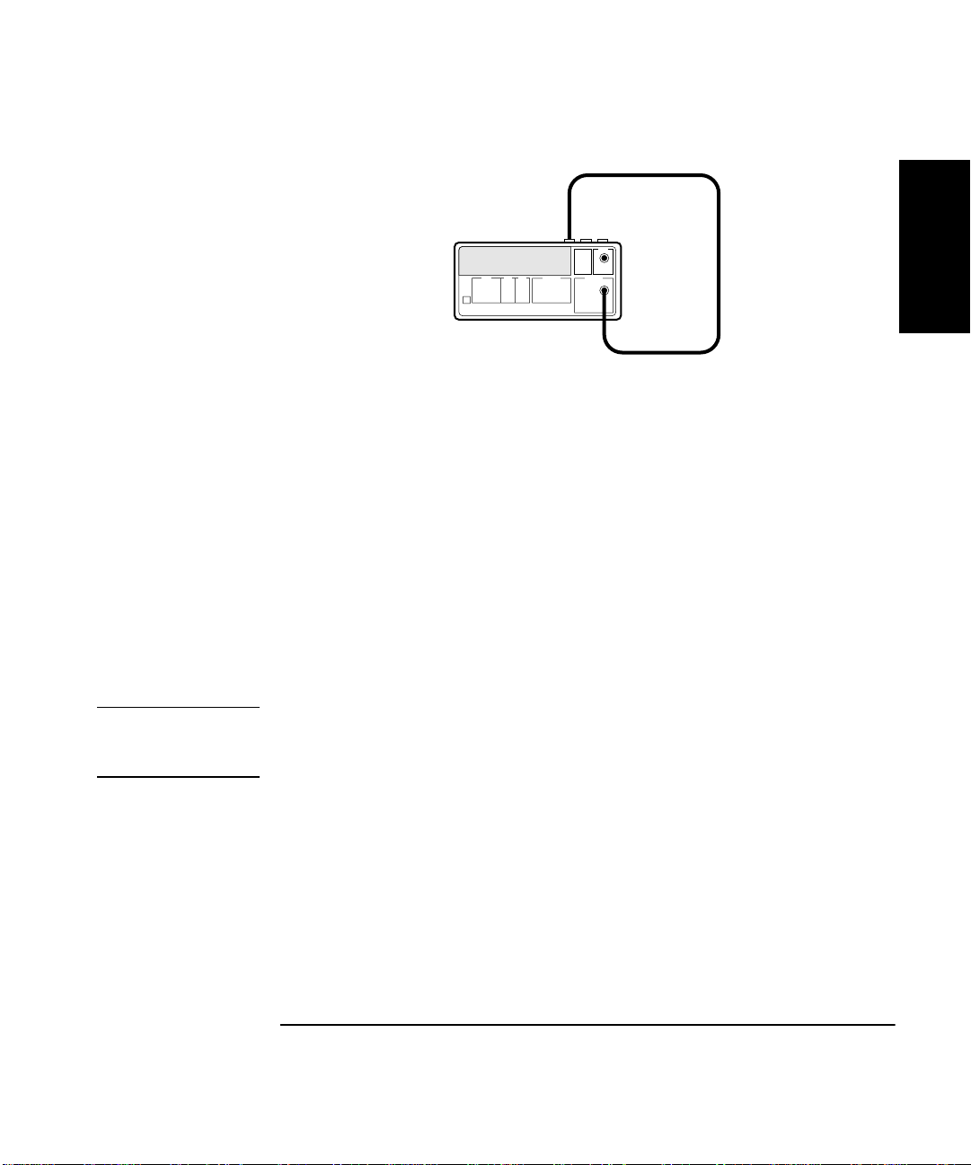
7 Connect the Counter’s rear-panel 10 MHz Out as shown in
Figure 1-1A or Figure 1-1B, depending on which Counter you are
testing.
HP 53131A/132A
Counter
Channel 1
10 MHz
Out
(rear panel)
Channel 2
BNC Tee
Figure 1-1A. Operational Verification Setup for HP 53131A/132A
1-6 Assembly-Level Service Guide
Page 29
Chapter 1 Performance Tests
HP 53131A/132A/181A Operational Verification
HP 53181A
Counter
10 MHz
Out
(rear panel)
Channel 1
Figure 1-1B. Operational Verification Setup for HP 53181A
8 Depending on which Counter you are testing, verify the
appropriate reading as shown below:
For HP 53131A and HP 53181A, verify a reading of 10.000,000,00 MHz.
For the HP 53132A, verify a reading of 10.000,000,000 MHz.
9 For HP 53131A/132A, mark Pass or Fail in the HP 53131A/132A
Performance Test Record on page 1-41, Test 2.
9’ For HP 53181A, mark Pass or Fail in the HP 53181A Performance
Test Record on page 1-71, Test 2.
1
NOTE
The remaining steps apply to the HP 53131A and HP 53132A only
since the HP 53181A does not have a standard Channel 2 input.
For the HP 53181A, proceed to the following “Run Self Test” section.
10 Press Freq & Ratio key until
FREQUENCY 2
is displayed to select
Channel 2 for frequency measurements.
For the HP 53131A, verify a reading of 10.000,000,00 MHz.
For the HP 53132A, verify a reading of 10.000,000,000 MHz.
11 For HP 53131A/132A, mark Pass or Fail in the HP 53131A/132A
Performance Test Record on page 1-41, Test 3.
Assembly-Level Service Guide 1-7
Page 30
Chapter 1 Performance Tests
HP 53131A/132A/181A Operational Verification
Run Self Test
1 Disconnect the input signals from the Counter.
1
2 Power down (turn off the Counter), press and hold Recall (Utility)
key, then press POWER key.
3Press Recall key until
TEST: ALL ?
is displayed.
4Press Enter key.
Observe that
If
ALL: FAIL
ALL: PASS
is displayed or a failure is indicated, refer to the
is displayed after the self test is completed.
troubleshooting section in Chapter 2, “Service,” of this guide.
5 For HP 53131A/132A, mark Pass or Fail in the HP 53131A/132A
Performance Test Record on page 1-41, Test 4.
5’ For HP 53181A, mark Pass or Fail in the HP 53181A Performance
Test Record on page 1-71, Test 3.
Termination Check
1Cycle the POWER key to preset the Counter.
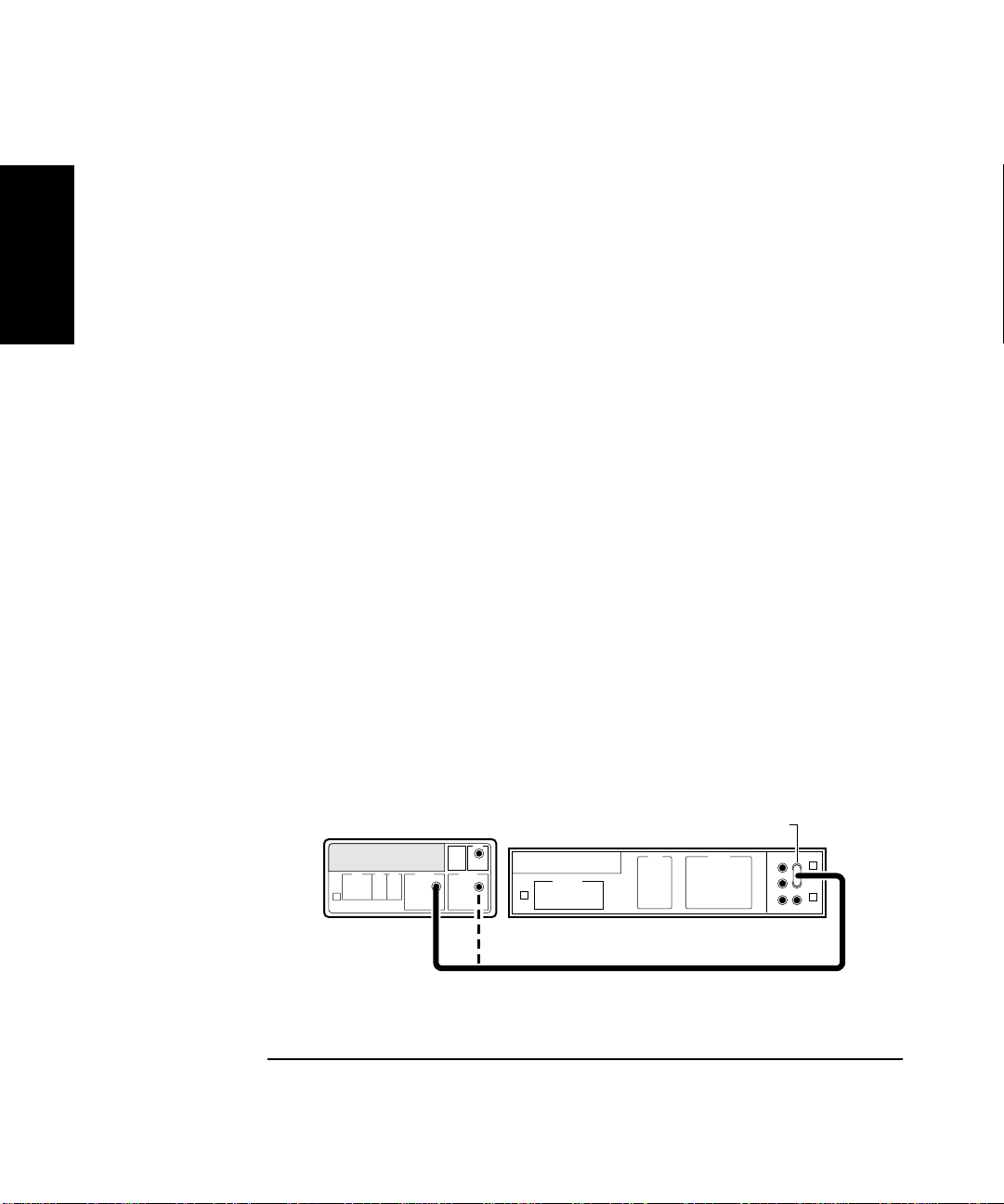
2 Connect a digital voltmeter (DVM) to CHANNEL 1 as shown in
Figure 1-2, and set it to measure ohms (set DVM to appropriate
Ω
range).
Counter
HP 53131A/132A is shown in abo ve figure. This setup fo r the HP53181A requires a connection to Channel 1 only.
HP 3458A
Digital Multimeter
BNC - to - Dual
Banana Plug
Figure 1-2. Termination Check Setup
1-8 Assembly-Level Service Guide
Page 31

Chapter 1 Performance Tests
HP 53131A/132A/181A Operational Verification
3 Press Channel 1 50Ω/1MΩ key.
The LED turns on, indicating a 50Ω input impedance for Channel 1.
4 Press Channel 1 DC/AC key.
The LED turns on, indicating DC input coupling for Channel 1.
5 Verify the DVM reads 51.1Ω ± 3Ω.
6 For HP 53131A/132A, mark Pass or Fail in the HP 53131A/132A
Performance Test Record on page 1-41, Test 5a.
6’ For HP 53181A, mark Pass or Fail in the HP 53181A Performance
Test Record on page 1-71, Test 4a.
7 Press Channel 1 50Ω/1MΩ key.
The LED turns off, indicating a 1 MΩ input impedance for Channel 1.
1
8 Verify the DVM reads approximately 1.0000000 MOHM.
9 For HP 53131A/132A, mark Pass or Fail in the HP 53131A/132A
Performance Test Record on page 1-41, Test 5b.
9’ For HP 53181A, mark Pass or Fail in the HP 53181A Performance
Test Record on page 1-71, Test 4b.
10 Repeat steps 3 through 9 for Channel 2 for the HP 53131A/132A
Counter ONLY since the HP 53181A Counter does not have a
standard Channel 2.
11 For HP 53131A/132A, mark Pass or Fail in the HP 53131A/132A
Performance Test Record on page 1-41, Tests 6a and 6b.
12 Disconnect the test setup.
Assembly-Level Service Guide 1-9
Page 32

Chapter 1 Performance Tests
HP 53131A/132A/181A Operational Verification
External Arm Test (HP 53131A/132A Only)
This test verifies the External Arm port of the HP 53131A and HP 53132A
Counter is operational.
1
Equipment
HP 8663A Synthesized Signal Generator
HP 8130A Pulse Generator (or equivalent)
HP 10100C 50Ω Feedthrough
HP 10503A BNC Cables (2)
HP 1250-0780 N-to-BNC Connector
Counter Setup
1Cycle the POWER key to preset the Counter.
2 Set the Counter as follows:
Other Meas,
Gate & ExtArm,
3 Set CHANNEL 1 input conditions to:
Trigger/Sensitivity,
Trigger/Sensitivity,
50Ω/1MΩ, 50
DC/AC, DC
X10 Attenuator, Off
100kHz Filter, Off
1-10 Assembly-Level Service Guide
TOTALIZE 1
GATE: EXTERNL (ENTER)
AUTO TRG: ON
LEVEL: 50 PCT
Ω
Page 33

Chapter 1 Performance Tests
HP 53131A/132A/181A Operational Verification
Procedure
1 Set the Pulse Generator to the following:
PERIOD: 20 µs
WIDTH: 5 µs
High: 3.00 V Low : 0.8 V
Trailing/Leading : 1.0 ns
Input Mode: TRIG
2 Connect the equipment as shown in Figure 1-3.
HP 8130A
Pulse Generator
Feedthrough
50Ω
Ext Arm
(rear panel)
HP 8663A
Synthesized Signal Generator
Counter
1
Output
Channel 1
Output
N-to-BNC
Connector
Figure 1-3. External Arm Test Setup (HP 53131A/132A Only)
Assembly-Level Service Guide 1-11
Page 34

Chapter 1 Performance Tests
HP 53131A/132A/181A Operational Verification
3 Set the HP 8663A to output a 200 MHz, 100 mV sine wave signal to
Channel 1.
1
4 On the Counter, Press Run key.
5 Send a single pulse by pressing the MAN key on the HP 8130A, and
observe that with each press the
The Counter should display approximately 1000.
6 For HP 53131A/132A, mark Pass or Fail in the HP 53131A/132A
Performance Test Record on page 1-41, Test 7.
7 Disconnect the test setup.
Gate
annunciator flashes.
External Timebase Tests
These tests verify the External Timebase 1, 5, 10 MHz specifications of
the HP 53131A and HP 53181A Counters by checking that TIMEBASE
AUTO allows the Counter to be synchronized to the external reference.
Note that the HP 53132A only operates with the 10 MHz external
timebase; therefore, perform the procedure in the section titled
“10 MHz External Timebase Input for the HP 53132A” on page 1-15
to verify that TIMEBASE AUTO allows the Counter to be synchronized to
the external reference.
Equipment
HP 3325B Synthesizers (2)
HP 10100C 50W Feedthrough
HP 10503 BNC Cables (2)
1-12 Assembly-Level Service Guide
Page 35

Chapter 1 Performance Tests
HP 53131A/132A/181A Operational Verification
1 MHz External Timebase Input (HP 53131A and HP 53181A Only)
1 Connect the equipment as shown in Figure 1-4.
HP 3325B
Synthesizer #1
50Ω
Feedthrough
Ref. In
(rear panel)
HP 3325B
Synthesizer #2
Counter
Channel 1
Output
Output
Figure 1-4. External Timebase Test Setup
2Cycle the POWER key to preset the Counter.
3 Set Synthesizer #1 (i.e., the HP 3325B connected to the rear-panel
Ref In input of the Counter via a 50Ω feedthrough) to output a
1 MHz, 200 mV rms sine wave signal.
1
4 Set Synthesizer #2 (i.e., the HP 3325B connected to Channel 1) to
output a 2 MHz, 100 mV rms square wave signal.
Verify the Counter displays a reading of approximately 2 MHz and the
ExtRef annunciator is lit.
5 For HP 53131A, mark Pass or Fail in the HP 53131A/132A
Performance Test Record on page 1-41, Test 8a.
Assembly-Level Service Guide 1-13
Page 36

Chapter 1 Performance Tests
HP 53131A/132A/181A Operational Verification
5’ For HP 53181A, mark Pass or Fail in the HP 53181A Performance
Test Record on page 1-71, Test 5a.
1
Only)
1 Change the frequency of Synthesizer # 1, which is connected to
the Counter’s rear-panel Ref In input to 5 MHz.
2 On the Counter, press Run key.
Verify the Counter displays a reading of approximately 2 MHz and the
ExtRef annunciator is lit.
3 For HP 53131A, mark Pass or Fail in the HP 53131A/132A
Performance Test Record on page 1-41, Test 8b.
3’ For HP 53181A, mark Pass or Fail in the HP 53181A Performance
Test Record on page 1-71, Test 5b.
10 MHz External Timebase Input (HP 53131A and HP 53181A Only)
1 Change the frequency of Synthesizer #1, which is connected to the
Counter’s rear-panel Ref In input to 10 MHz.
2 On the Counter, press Run key.
5 MHz External Timebase Input (HP 53131A and HP 53181A
Verify the Counter displays a reading of approximately 2 MHz and the
ExtRef annunciator is lit.
3 For HP 53131A, mark Pass or Fail in the HP 53131A/132A
Performance Test Record on page 1-41, Test 8c.
3’ For HP 53181A, mark Pass or Fail in the HP 53181A Performance
Test Record on page 1-71, Test 5c.
4 Disconnect the test setup.
This completes the Operational Verification for the HP 53131A and
HP 53181A.
1-14 Assembly-Level Service Guide
Page 37

Chapter 1 Performance Tests
HP 53131A/132A/181A Operational Verification
10 MHz External Timebase Input for the HP 53132A
1 Connect the equipment as shown in Figure 1-4.
2 Set Synthesizer #1 (i.e., the HP 3325B that is connected to the
rear-panel Ref In input of the Counter via a 50Ω feedthrough) to
output a 10 MHz, 200 mV rms sine wave signal.
3 Set Synthesizer #2 (i.e., the HP 3325B that is connected to
Channel 1) to output a 2 MHz, 100 mV rms square wave signal.
Verify the Counter displays a reading of approximately 2 MHz and the
ExtRef annunciator is lit.
4 Mark Pass or Fail in the HP 53131A/132A Performance Test
Record on page 1-41, Test 8d.
5 Disconnect the test setup.
This completes the Operational Verification for the HP 53132A.
1
Assembly-Level Service Guide 1-15
Page 38

Chapter 1 Performance Tests
HP 53131A/132A Complete Performance Tests
HP 53131A/132A Complete Performance
1
Tests
The specifications of the HP 53131A/132A Universal Counter can be
verified by performing the performance tests provided in this section.
Table 1-2 lists a summary of the HP 53131A/132A performance tests.
Record the results of the performance tests in the appropriate
place on HP 53131A/132A Performance Test Record, which starts
on page 1-41.
(Note: the complete performance tests for the HP 531 81A Frequency
Counter begin on page 1-47 of this chapter.)
NOTE
To perform valid testing of the specifications, warm up the Counter and
test equipment for 30 minutes.
Table 1-2. The HP 53131A/132A Performance Tests
Page Number*Test Description
page 1-17 Test 1: Time Interval (HP 53131A/132A Only)
page 1-19 Test 2: Trigger Level (HP 53131A/132A Only)
page 1-22 Test 3: Channels 1 and 2 Frequency Sensitivity
(HP 53131A/132A Only)
page 1-27 Test 4: Channels 1 and 2 Frequency Accuracy
(HP 53131A/132A Only)
page 1-30 Test 5: Option 030/050/124 Channel 3 Frequency Sensitivity
(HP 53131A/132A Only)
page 1-35 Test 6: Option 030/050/124 Channel 3 Frequency Accuracy
(HP 53131A/132A Only)
page 1-37 Test 7: Peak Volts, Channels 1 and 2 (HP53131A/132A Only)
page 1-40 HP 53131A/132A HP-IB Verification Program (Optional)
* Other Counter measurement functions (e.g., Period) are mathematically derived by the microprocessor from
the parameters verified by these performance tests. If the Counter passes the performance tests, the other
measurement functions are functioning to specifications.
1-16 Assembly-Level Service Guide
Page 39

Chapter 1 Performance Tests
Test 1: Time Interval (HP 53131A/132A Only)
Test 1: Time Interval (HP 53131A/132A Only)
This test verifies the Time Interval specifications between Channels 1 and 2.
Equipment
HP 8130A Pulse Generator (or equivalent)
HP 10503A BNC Cable
Counter Setup
1Cycle the POWER key to preset the Counter.
2Press Time & Period key until
3 Set CHANNEL 1 input conditions to:
Trigger/Sensitivity,
Trigger/Sensitivity,
Trigger/Sensitivity,
50Ω/1MΩ, 50
DC/AC, DC
X10 Attenuate, Off
100kHz Filter, Off
4 Set CHANNEL 2 input conditions to:
Ω
AUTO TRG: OFF
LEVEL: .500V (Enter)
COMMON 1: ON
TI 1 TO 2
is displayed.
1
Trigger/Sensitivity,
Trigger/Sensitivity,
Trigger/Sensitivity,
50Ω/1MΩ, 50
DC/AC, DC
X10 Attenuate, Off
100kHz Filter, Off
Assembly-Level Service Guide 1-17
Ω
AUTO TRG: OFF
LEVEL: .500V (Enter)
SLOPE: NEG
Page 40

Chapter 1 Performance Tests
Test 1: Time Interval (HP 53131A/132A Only)
Procedure
1 Connect the pulse generator si gnal to Channel 1 of the C ounter as
shown in Figure 1-5.
1
HP 8130A
HP53131A/132
Counter
Pulse Generator
Channel 1
Figure 1-5. Time Interval (Channel 1 TO 2) Test Setup
2 Set the Pulse Generator to the following:
PERIOD: 10 µs
WIDTH: 150 ns
High: 1.00 V Low : 0.00 V
Input Mode: Normal
3 On the Counter, Press Single/Stop key.
The HP 53131A Counter should display 0.1500 µs ±0.0040 µs.
The HP 53132A Counter should display 0.1500 µs ±0.0025 µs.
4 Record this value in the appropriate place in the Performance
Test Record (Test 1, Line 1 for HP 53131A or Test 1, Line 2 for
HP 53132A).
5 Disconnect the test setup.
Output
1-18 Assembly-Level Service Guide
Page 41

Chapter 1 Performance Tests
Test 2: Trigger Level (HP 53131A/132A Only)
Test 2: Trigger Level (HP 53131A/132A Only)
This test verifies the Trigger Level accuracy of the HP 53131A and
HP 53132A Universal Counters.
Equipment
HP 3325B Synthesizer
HP 10503A BNC Cable
Counter Setup
1Cycle the POWER key to preset the Counter.
2 Set CHANNEL 1 input conditions to:
Trigger/Sensitivity,
Trigger/Sensitivity,
50Ω/1MΩ, 50
DC/AC, DC
X10 Attenuate, Off
100kHz Filter, Off
3 Set CHANNEL 2 input conditions to:
Trigger/Sensitivity,
Trigger/Sensitivity,
50Ω/1MΩ, 50
DC/AC, DC
X10 Attenuate, Off
100kHz Filter, Off
Ω
Ω
AUTO TRG: OFF
LEVEL: 0.000V
AUTO TRG: OFF
LEVEL: 0.000V
1
Assembly-Level Service Guide 1-19
Page 42

Chapter 1 Performance Tests
Test 2: Trigger Level (HP 53131A/132A Only)
Procedure
1 Connect the output of the HP 3325B to Channel 1 of the Counter
as shown in Figure 1-6.
1
HP 3325B
HP 53131A/132A
Counter
Synthesizer
Channel 1
Channel 2
Output
Figure 1-6. Trigger Level Test Setup
2 Set the HP 3325B to output a 1 MHz, 80 mVp-p s quare wave signal.
3 Set the HP 3325B DC OFFSET to −60 mV.
4 On the Counter, press Run key.
5 Now, increment the dc offset on the HP 3325B by +1 mV until the
Counter’s
Gate
annunciator flashes and continue incrementing
until the Counter displays a stable reading of approximately
1MHz.
Observe the offset value on the display of the HP 3325B.
Record the dc offset value__________ mV.
6 Add the upper peak voltage (40 mV) of the 80 mV p-p signal to the
offset value in step 5 (For example, −24 mV + 40 mV = 16 mV).
This is the upper hysteresis level.
Record the upper hysteresis l evel__________ mV.
1-20 Assembly-Level Service Guide
Page 43

Chapter 1 Performance Tests
Test 2: Trigger Level (HP 53131A/132A Only)
7 In the Counter’s Channel 1 Trigger/Sensitivity menu, change the
SLOPE to NEG.
8 Set the HP 3325B DC OFFSET to +60 mV.
9 On the Counter, press Run key.
10 Now, decrement the offset on the HP 3325B by −1 mV until the
Counter’s
until the Counter displays a stable reading of approximately
1MHz.
Observe the offset value on the display of the HP 3325B.
Record the value__________ mV.
11 Add the lower peak voltage (−40mV) of the 80 mVp-p signal to the
offset value in step 10 (for example, 21 mV − 40 mV = −19 mv.)
This result is the lower hysteresis level.
Record the lower hysteresis level __________ mV.
12 Now, add the upper hysteresis value (recorded in step 6) and
lower hysteresis value (recorded in step 11).
This is the trigger level; it should be 0.0 V ±15 mV.
Gate
annunciator flashes and continue decrementing
1
13 Record the trigger level value in the appropriate place in the
Performance Test Record (Test 2, Line 1).
14 Repeat steps 1 through 13 for Channel 2.
15 Record the trigger level value in the appropriate place in the
Performance Test Record (Test 2, Line 2).
16 Disconnect the test setup.
Assembly-Level Service Guide 1-21
Page 44

Chapter 1 Performance Tests
Test 3: Channels 1 and 2 Frequency Sensitivity (HP 53131A/132A Only)
Test 3: Channels 1 and 2 Frequency
1
Sensitivity (HP 53131A/132A Only)
This set of tests verifies frequency sensitivity specifications of the
HP 53131A and 53132A Universal Counters.
Equipment
HP 8663A Synthesized Signal Generator
HP 1250-0780 Type N-to-BNC Connector
HP 10100C 50Ω Feedthrough
HP 10503A BNC Cables (2)
Counter Setup
1Cycle the POWER key to preset the Counter.
2 Set CHANNEL 1 input conditions to:
Trigger/Sensitivity,
Trigger/Sensitivity,
50Ω/1MΩ, 50
DC/AC, DC
X10 Attenuate, Off
100kHz Filter, Off
Ω
AUTO TRG: OFF
LEVEL: 0.000 V
3 Set CHANNEL 2 input conditions to:
Trigger/Sensitivity,
Trigger/Sensitivity,
50Ω/1MΩ, 50
DC/AC, DC
X10 Attenuate, Off
100kHz Filter, Off
1-22 Assembly-Level Service Guide
Ω
AUTO TRG: OFF
LEVEL: 0.000 V
Page 45

Chapter 1 Performance Tests
Test 3: Channels 1 and 2 Frequency Sensitivity (HP 53131A/132A Only)
100 kHz to 100 MHz Sensitivity for HP 53131A/132A
1 Connect the timebase output of the unit with the better timebase
to the timebase reference input of the other unit as shown in
Figure 1-7.
For this test, make sure you always use the unit (HP 53131A/132A or
HP 8663A) that contains the better 10 MHz timebase as the output source
as shown in Figure 1-7.
HP 8663A
HP 53131A/132A
Counter
50Ω
Feedthrough
Ref. In
(rear panel)
Synthesized
Signal Generator
Output
(rear panel)
1
N-to-BNC
Channel 1
Output
Connector
OR
HP 8663A
Synthesized
Signal Generator
HP 53131A/132A
Counter
Channel 1
50Ω
Feedthrough
10 MHz
Output
(rear panel)
Figure 1-7. Channels 1 and 2 Frequency Sensitivity Test Setup
Assembly-Level Service Guide 1-23
Input
(rear panel)
Output
N-to-BNC
Connector
Page 46

Chapter 1 Performance Tests
Test 3: Channels 1 and 2 Frequency Sensitivity (HP 53131A/132A Only)
2 Set the HP 8663A Signal Generator to output a 100 MHz,
−
35.0 dBm sine wave signal (−20.0 dBm for Option 060 Rear
Terminals) to the Counter’s Channel 1 input.
1
3 On the Counter, press Run key.
4 In 0.1 dB steps, increase the power level until the Counter
displays a stable reading of 100 MHz.
The Counter should display 100 MHz when the signal generator level is
≤−
21.0 dBm (20 mVrms). Counters with Option 060 should display
100 MHz when the signal generator level is
5 Sweep the frequency from 100 MHz to 100 kHz. For Option 060,
sweep frequencies from 225 MHz to 100 kHz.
The Counter should read frequencies from 100 MHz to 100 kHz at an
input power level of
Option 060 should read frequencies from 225 MHz t o 100 kH z at
9.5 dBm (75 mVrms).
6 Record the actual reading in the appropriate place in the
Performance Test Record (Test 3, Line 1).
If you are testing a Counter with front-panel terminals (Standard),
record the reading on Line 1 of the Standard portion of the test record.
If you are testing a Counter with rear terminals (Option 060),
record the reading on Line 1 of the Option 060 portion of the test record.
≤ −
21.0 dBm (20 mVrms). Count ers with
≤ −
9.5 dBm (75 mVrms).
≤−
NOTE
DO NOT test the front terminals if rear terminals are installed. The front
terminal performance is not specified when the rear terminals are installed.
7 Connect the HP 8663A to Channel 2 of the Counter.
8 On the Counter, press Freq & Ratio key until
displayed.
9 Repeat steps 2 through 5 for Channel 2.
1-24 Assembly-Level Service Guide
FREQUENCY 2
is
Page 47

Chapter 1 Performance Tests
Test 3: Channels 1 and 2 Frequency Sensitivity (HP 53131A/132A Only)
10 Record the actual reading in the appropriate place in the
Performance Test Record (Test 3, Line 2).
NOTE
If you are testing a Counter with front-panel terminals (Standard),
record the reading on Line 2 of the Standard portion of the test record.
If you are testing a Counter with rear terminals (Option 060),
record the reading on Line 2 of the Option 060 portion of the test record.
The remaining sensitivity procedures are NOT required for Counters that
contain Option 060 Rear Terminals; thus, this completes the sensitivity
portion of the Frequency Performance Test. Go to the Frequen cy Accuracy
Test on page 1-27.
100 MHz to 200 MHz Sensitivity for HP 53131A/132A
1 Leave the signal generator connected to Channel 2. Change the
signal generator settings to 200 MHz at −30 dBm.
2 On the Counter, press Run key.
3 Increase the power level by 0.1 dB steps until the Counter
displays a stable 200 MHz reading.
The Counter should display 200 MHz when the input signal level is
≤−
17.5 dBm (30 mVrms).
1
4 Sweep the signal generator frequency from 200 MHz to 100 MHz.
The Counter should read frequencies from 200 MHz to 100 MHz when the
input signal level is
5 Record the actual reading in the Performance Test Record
(Test 3, Line 3).
6 Connect the signal generator to Channel 1.
7 On the Counter, press Freq & Ratio key until
displayed.
Assembly-Level Service Guide 1-25
≤ −
17.5 dBm (30 mVrms).
Frequency 1
is
Page 48

Chapter 1 Performance Tests
Test 3: Channels 1 and 2 Frequency Sensitivity (HP 53131A/132A Only)
8 Repeat steps 1 through 4 for Channel 1.
9 Record the actual reading in the Performance Test Record
(Test 3, Line 4).
1
200 MHz to 225 MHz Sensitivity for HP 53131A/132A
1 Leave the signal generator connected to Channel 1. Change the
signal generator settings to 225 MHz at −30 dBm.
2 On the Counter, press Run key.
3 Increase the power level by 0.1 dB steps until the Counter
displays a stable reading of 225 MHz.
The Counter should read 225 MHz when the input signal level is
≤ −
15.0 dBm (40 mVrms).
4 Sweep the signal generator frequency from 225 MHz to 200 MHz.
The Counter should read frequencies from 225 MHz to 200 MHz when the
input signal level is
5 Record the actual reading in the Performance Test Record
(Test 3, Line 5).
6 Connect the signal generator to Channel 2.
7 On the Counter, press Freq & Ratio key until
displayed.
8 Repeat steps 1 through 4 for Channel 2.
9 Record the actual reading in the Performance Test Record
(Test 3, Line 6).
10 Disconnect the test setup.
1-26 Assembly-Level Service Guide
≤ −
15.0 dBm (40 mVrms).
Frequency 2
is
Page 49

Chapter 1 Performance Tests
Test 4: Channels 1 and 2 Frequency Accuracy (HP 53131A/132A Only)
Test 4: Channels 1 and 2 Frequency Accuracy
(HP 53131A/132A Only)
This set of tests verifies the frequency accuracy specifications of the
HP 53131A and HP 53132A Universal Counters.
Equipment
HP 8663A Synthesized Signal Generator
HP 1250-0780 Type N-to-BNC Connector
HP 10100C 50Ω Feedthrough
HP 10503A BNC Cables (2)
Counter Setup
1Cycle the POWER key to preset the Counter.
2 Using the Gate & ExtArm key, set the gate time to
3 Set CHANNEL 1 input conditions to:
Trigger/Sensitivity,
Trigger/Sensitivity,
50Ω/1MΩ, 50
DC/AC, DC
X10 Attenuate, Off
100kHz Filter, Off
Ω
AUTO TRG: OFF
LEVEL: 0.000 V
TIME 1.000 s
1
.
4 Set CHANNEL 2 input conditions to:
Trigger/Sensitivity,
Trigger/Sensitivity,
50Ω/1MΩ, 50
DC/AC, DC
X10 Attenuate, Off
100kHz Filter, Off
Assembly-Level Service Guide 1-27
Ω
AUTO TRG: OFF
LEVEL: 0.000 V
Page 50

1
HP 53131A/132A
Counter
Chapter 1 Performance Tests
Test 4: Channels 1 and 2 Frequency Accuracy (HP 53131A/132A Only)
Procedure
1 Connect the equipment as shown in Figure 1-8 with the signal
generator connected to Channel 1 of the Counter.
50Ω
Feedthrough
Ref. In
(rear panel)
HP 8663A
Synthesized Signal Generator
Channel 2
(rear panel)
Input
Channel 1
Figure 1-8. Channels 1 and 2 Frequency Accuracy Test Setup
2 Set the Signal Generator to output 1 MHz at −7 dBm.
3 On the Counter, press Run key.
Verify the HP 53131A Counter reads 1 MHz ±1 mHz.
Verify the HP 53132A Counter reads 1 MHz ±200 µHz.
4 Record the actual reading in the appropriate place in the
Performance Test Record (Test 4, Line 1 for HP 53131A or Test 4,
Line 3 for HP 53132A.
1-28 Assembly-Level Service Guide
Output
N-to-BNC
Connector
Page 51

Chapter 1 Performance Tests
Test 4: Channels 1 and 2 Frequency Accuracy (HP 53131A/132A Only)
5 Change the signal generator frequency to 100 MHz.
Verify the HP 53131A Counter reads 100 MHz ±70 mHz.
Verify the HP 53132A Counter reads 100 MHz ±15 mHz.
6 Record the actual reading in the appropriate place in the
Performance Test Record (Test 4, Line 5 for HP 53131A or Test 4,
Line 7 for HP 53132A).
7 Change the signal generator frequency to 200 MHz.
Verify the HP 53131A Counter reads 200 MHz ±130 mHz.
Verify the HP 53132A Counter reads 200 MHz ±30 mHz.
8 Record the actual reading in the appropriate place in
Performance Test Record (Test 4, Line 9 for HP 53131A or Test 4,
Line 11 for HP 53132A).
1
9 Change the signal generator frequency to 225 MHz.
Verify the HP 53131A Counter reads 225 MHz ±150 mHz.
Verify the HP 53132A Counter reads 225 MHz ±35 mHz.
10 Record the actual reading in the appropriate place in the
Performance Test Record (Test 4, Line 13 for HP 53131A or Test 4,
Line 15 for HP 53132A).
11 Connect the signal generator to Channel 2.
12 On the Counter, press Freq & Ratio key until
displayed.
13 Repeat steps 2 through 9 for Channel 2.
14 Record the actual readings in the appropriate places in the
Performance Test Record.
15 Disconnect the test setup.
Assembly-Level Service Guide 1-29
Frequency 1
is
Page 52

Chapter 1 Performance Tests
Test 5: Option 030/050/124 Channel 3 Frequency Sensitivity (HP 53131A/132A Only)
Test 5: Option 030/050/124 Channel 3
1
Only)
This test verifies the frequency range, and sensitivity of the optional
3-GHz and 5-GHz Channel 3 (Option 030/050/124) for the HP 53131A and
the HP 53132A Universal Counters.
Equipment
HP 8663A Synthesized Signal Generator (not needed for Option 050)
HP 8340B Sweep Oscillator
HP 1250-0780 Type N-to-BNC Connector (not needed for Option 050)
HP 10503A BNC Cable(2)
HP 10100C 50Ω Feedthrough
HP 11500D N-N Cable (Option 050 only)
HP 1250-1250 N(M) to SMA(F)
HP 1250-0777 N(F) to N(F)
Counter Setup
1Cycle the POWER key to preset the Counter.
2 Set the Counter as follows:
Frequency Sensitivity (HP 53131A/132A
Freq & Ratio,
FREQUENCY 3
1-30 Assembly-Level Service Guide
Page 53

Chapter 1 Performance Tests
Test 5: Option 030/050/124 Channel 3 Frequency Sensitivity (HP
53131A/132A Only)
100 MHz to 2.5 GHz Sensitivity for HP 53131A/132A
Option 030 only
HP 53131A/132A
Counter
1 Set the HP 8663B Synthesized Signal Generator to output a
2500 MHz, −40 dBm sine wave, and connect the signal to Channel 3
of the Counter as shown in Figure 1-9.
Frequency Standard
(switch set to EXT)
Output
Input
(rear panel)
50Ω
Feedthrough
Ref. In
(rear panel)
HP 8340B
Sweep Oscillator
HP 8663A
Synthesized Signal Generator
1
Channel 3
Output
N-to-BNC
Connector
Figure 1-9. Option 030/050/124 Channel 3 Frequency Sensitivity and Accuracy Test Setup
2 On the Counter, Press Run key.
Assembly-Level Service Guide 1-31
Page 54

Chapter 1 Performance Tests
Test 5: Option 030/050/124 Channel 3 Frequency Sensitivity (HP
53131A/132A Only)
3 Increase the power level in 5 d B steps until the Counter displays a
stable reading of approximately 2.5 GHz.
The Counter should display 2.5 GHz at
≤ −
27.0 dBm (10 mVrms).
1
4 Sweep the frequencies from 2.5 GHz to 200 MHz.
The Counter should read frequencies from 2.5 GHz to 200 MHz at
≤ −
27.0 dBm (10 mVrms).
5 Record the actual reading in the Performance Test Record
(Test 5, Line 1).
2.7 to 3.0 GHz Sensitivity for Option 030 only
1 Disconnect the HP 8663A Synthesized Signal Generator from the
Counter (see Figure 1-9), and connect the HP 8340B Sweep
Oscillator to Channel 3 of the Counter.
2 Change the settings of the Sweep Oscillator to 3.0 GHz, −40 dBm.
3 Increase the power level in 1 d B steps until the Counter displays a
stable reading of approximately 3.0 GHz.
The Counter should display 3.0 GHz at
4 Sweep the frequencies from 3.0 GHz to 2.7 GHz.
≤ −
21.0 dBm.
The Counter should read frequencies from 3.0 to 2.7 GHz at
5 Record the actual reading in the Performance Test Record
(Test 5, Line 2).
6 Disconnect the test setup.
1-32 Assembly-Level Service Guide
≤ −
21.0 dBm.
Page 55

Chapter 1 Performance Tests
Test 5: Option 030/050/124 Channel 3 Frequency Sensitivity (HP
53131A/132A Only)
200 MHz to 5.0 GHz Sensitivity for HP 53131A/132A (Option 050 only)
NOTE
1 Connect the 8340B Sweep Oscillator to Channel 3 of the counter.
2 Change the settings of the Sweep Oscillator to 5.0 GHz, −40 dBm.
3 Increase the power level in 1 d B steps until the Counter displays a
stable reading of approximately 5.0 GHz.
The Counter should display 5.0 GHz at
Use a power meter and sensor to ensure the accuracy of the power being
input.
4 Sweep the frequencies from 200 MHz to 5.0 GHz.
The Counter should read frequencies from 200 MHz to 5.0 GHz at ≤−3dBm.
5 Record the actual reading in the Performance Test Record
(Test 5, Line 3).
6 Disconnect the test setup.
≤ −
23 dBm.
1
Assembly-Level Service Guide 1-33
Page 56

Chapter 1 Performance Tests
Test 5: Option 030/050/124 Channel 3 Frequency Sensitivity (HP
53131A/132A Only)
200 MHz to 12.4 GHz Sensitivity for HP 53131A/132A (Option 124 only)
1 Connect the 8340B Sweep Oscillator to Channel 3 of the counter.
1
2 Change the settings of the Sweep Oscillator to 12.4 GHz, −40 dBm.
3 Increase the power level in 1 d B steps until the Counter displays a
stable reading of approximately 12.4 GHz.
NOTE
The Counter should display 12.4 GHz at
Use a power meter and sensor to ensure the accuracy of the power being
input.
4 Sweep the frequencies from 200 MHz to 12.4 GHz.
The Counter should read frequencies from 200 MHz to 12.4 GHz
at ≤−3dBm.
5 Record the actual reading in the Performance Test Record
(Test 5, Line 4).
6 Disconnect the test setup.
≤ −
23 dBm.
1-34 Assembly-Level Service Guide
Page 57

Chapter 1 Performance Tests
Test 6: Option 030/050/124 Channel 3 Frequency Accuracy
(HP 53131A/132A Only)
Test 6: Option 030/050/124 Channel 3
Frequency Accuracy (HP 53131A/132A Only)
This test verifies the frequency accuracy of the optional 3-GHz or 5-GHz
Channel 3 (Option 030).
Equipment
HP 8663A Synthesized Signal Generator (Option 030 only)
HP 8340B Sweep Oscillator
HP 1250-0780 Type N-to-BNC Connector (Option 030 only)
HP 10503A BNC Cable (2)
HP 10100C 50Ω Feedthrough
HP 11500D N-N Cable (Option 050 only)
HP 1250-1250 N(M) to SMA(F)
HP 1250-0777 N(F) to N(F)
Counter Setup
1Cycle the POWER key to preset the Counter.
2 Set the Counter as follows:
Freq & Ratio,
Gate & ExtArm,
FREQUENCY 3
TIME: TIME 1.000 s
1
Procedure
1 Connect equipment as shown in Figure 1-9.
(NOTE: For Options 050 and 124, skip steps 2 through 5.
Proceed to step 6.)
2 Set the HP 8663A Synthesized Signal Generator to output
100 MHz at −17.0 dBm.
Assembly-Level Service Guide 1-35
Page 58

Chapter 1 Performance Tests
Test 6: Option 030/050/124 Channel 3 Frequency Accuracy
(HP 53131A/132A Only)
3 On the Counter, press Run key.
Verify the HP 53131A Counter reads 100 MHz ±70 mHz.
1
Verify the HP 53132A Counter reads 100 MHz ±20 mHz.
4 Record the actual reading in the Performance Test Record
(Test 6, Line 1 for HP 53131A or Test 6, Line 2 for HP 53132A).
5 Disconnect the HP 8663A output from Channel 3 of the Counter,
and connect the HP 8340B Sweep Oscillator output to Channel 3
of the Counter as shown in Figure 1-9.
6 Set the HP 8340B to output 3.0 GHz at −17.0 dBm.
Verify the HP 53131A Counter reads 3.0 GHz ±2 Hz.
Verify the HP 53132A Counter reads 3.0 GHz ±0.4 Hz.
7 Record the actual reading in the Performance Test Record
(Test 6, Line 3 for HP 53131A or Test 6, Line 4 for HP 53132A).
8 Set the HP 8340B to output 5.0 GHz at −17 dBm.
Verify the HP 53131A Counter reads 5.0 GHz ±3 Hz.
Verify the HP 53132A Counter reads 5.0 GHz ±0.7 Hz.
9 Record the actual reading in the Performance Test Record
(Test 6, Line 5 for HP 53131A or Test 6, Line 6 for HP 53132A).
10 Set the HP 8340B to output 12.4 GHz at −17 dBm. (This step is for
Option 124 only.)
Verify the HP 53131A Counter reads 12.4 GHz ±8 Hz.
Verify the HP 53132A Counter reads 12.4 GHz ±2 Hz.
11 Record the actual reading in the Performance Test Record
(Test 6, Line 7 for HP 53131A or Test 6, Line 8 for HP 53132A.)
12 Disconnect the test setup.
1-36 Assembly-Level Service Guide
Page 59

Chapter 1 Performance Tests
Test 7: Peak Volts, Channels 1 and 2 (HP 53131A/132A Only)
Test 7: Peak Volts, Channels 1 and 2
(HP 53131A/132A Only)
This test verifies the Peak Volts accuracy specification of the HP 53131A
and HP 53132A Universal Counters.
Equipment
HP 3325B Synthesizer
HP 10100C 50Ω Feedthrough
HP 10503A BNC Cable
Counter Setup
1Cycle the POWER key to preset the Counter.
2Press Other Meas key until
3 Set CHANNEL 1 input to:
50Ω/1MΩ, 50
X10 Attenuate, Off
100kHz Filter, Off
4 Set CHANNEL 2 input to:
Ω
VOLT PEAKS 1
is displayed.
1
50Ω/1MΩ, 50
X10 Attenuate, Off
100kHz Filter, Off
Assembly-Level Service Guide 1-37
Ω
Page 60

Chapter 1 Performance Tests
Test 7: Peak Volts, Channels 1 and 2 (HP 53131A/132A Only)
Volt Peak 1
1 Connect the equipment as shown in Figure 1-10.
1
HP 3325B
HP 53131A/132A
Counter
Channel 2
Synthesizer
Channel 1
Figure 1-10. Peak Volts Test Setup
2 Set the HP 3325B to output a 2 MHz, 2 Vp-p sine wave.
The Counter should display −1.00 ±0.12V for the negative peak of the sine
wave. This reading is displayed on the left side of the display.
Record the actual reading in the Performance Test Record
(Test 7, Line 1a).
Also, the Counter should display +1.00 ±0.12V for the positive peak of the
sine wave. This reading is displayed on the right side of the display.
Record the actual reading in the Performance Test Record
(Test 7, Line 1b).
Output
1-38 Assembly-Level Service Guide
Page 61

Chapter 1 Performance Tests
Test 7: Peak Volts, Channels 1 and 2 (HP 53131A/132A Only)
Volt Peak 2
1 Remove the signal from Channel 1 of the Counter and connect it
to Channel 2.
1
2Press Other Meas key until
The Counter should display -1.00 ±0.12V for the negative peak of the sine
wave. This reading is displayed on the left side of the display.
Record the actual reading in the Performance Test Record
(Test 7, Line 2a).
Also, the Counter should display +1.00 ±0.12V for the positive peak of the
sine wave. This reading is displayed on the right side of the display.
Record the actual reading in the Performance Test Record
(Test 7, Line 2b).
3 Disconnect the test setup.
VOLT PEAK 2
is displayed.
Assembly-Level Service Guide 1-39
Page 62

Chapter 1 Performance Tests
HP 53131A/132A HP-IB Verification Program (Optional)
HP 53131A/132A HP-IB Verification Program
1
(Optional)
The HP-IB Verification program exercises the HP 53131A/132A and
through various operating modes via the its HP-IB interface. If the
Counter successfully completes all phases of the verification program,
there is a high probability that the HP-IB interface is operating correctly.
If the Counter fails the verification program, refer to the troubleshooting
section in Chapter 2, “Service,” of this guide.
The HP-IB Verification program may be loaded into the HP 9000
series 200 or 300 Desktop Computer from the 3 1/2-inch disk
(HP P/N 53131-13501) or the 5 1/4-inch disk (HP P/N 53131-13502).
1 To run the program on the disk, insert the disk into the Desktop
Computer, load the program by typing Load “VER31”, and press
RUN key on the computer’s keyboard.
2 Follow the instructions displayed in the computer’s screen.
3 After running this program, record the result (Pass or Fail) on the
last page (page 1-46) of the HP 53131A/132A Performance Test
Record.
1-40 Assembly-Level Service Guide
Page 63

Chapter 1 Performance Tests
HP 53131A/132A Performance Test Record (Page 1 of 6)
HP 53131A/132A Performance Test Record
(Page 1 of 6)
Hewlett-Packard Model 53131A/132A Universal Counter
Serial Number: _________________________ Repair/Work Order No. __________________
Test Performed By: _____________________ Temperature: __________________________
Date: __________________________________ Relative Humidity: _____________________
Notes: _________________________________________________________________________
Test Number Operational Verification Test Results
Pass Fail
1 Power on Self Test qq
2 Channel 1, 10 MHz Test qq
3 Channel 2, 10 MHz Test qq
4 Run Self Test qq
5a Termination Check Ch 1, 50Ω qq
5b Termination Check Ch 1, 1MΩ qq
6a Termination Check Ch 2, 50Ω qq
6b Termination Check Ch 2, 1MΩ qq
7 External Arm Test qq
8a 1 MHz External Timebase Input Test (HP 53131A Only) qq
1
8b 5 MHz External Timebase Input Test (HP 53131A Only) qq
8c 10 MHz External Timebase Input Test (HP 53131A Only) qq
8d 10 MHz External Timebase Input Test for the HP 53132A qq
Assembly-Level Service Guide 1-41
Page 64

Chapter 1 Performance Tests
HP 53131A/132A Performance Test Record (Page 2 of 6)
HP 53131A/132A Performance Test Record
1
(Page 2 of 6)
Complete Performance Tests
Test
Number Test Description Minimum Actual Reading Maximum
1 Time Interval
(HP 53131A/132A
Only):
For HP 53131A
For HP 53132A
2 Trigger Level:
Channel 1
Channel 2
(HP 53131A/132A Only)
Test 3: Channels 1 and 2 Frequency Sensitivity (HP 53131A/132A Only)
Standard (Front Panel Terminals) Actual Reading Specific ation
100 kHz–100 MHz, Channel 1
100 kHz–100 MHz, Channel 2
100 MHz–200 MHz, Channel 2
100 MHz–200 MHz, Channel 1
200 MHz–225 MHz, Channel 1
200 MHz–225 MHz, Channel 2
0.1460 µs
0.1475 µs
−15 mV
−15 mV
1. _________ _
2. _________ _
3. _________ _
4. _________ _
5. _________ _
6. _________ _
1. __________
2. __________
1. __________
2. __________
≤ −21 dBm (20 mVrms)
≤ −21 dBm (20 mVrms)
≤ −17.5 dBm (30 mVrms)
≤ −17.5 dBm (30 mVrms)
≤ −15.0 dBm (40 mVrms)
≤ −15.0 dBm (40 mVrms)
0.1540 µs
0.1525 µs
+15 mV
+15 mV
Option 060 Rear Terminals Actual Reading Specification
100 kHz–225 MHz, Channel 1
100 kHz–225 MHz, Channel 2
1. _________ _
2. _________ _
≤ −9.5 dBm (75 mVrms)
≤ −9.5 dBm (75 mVrms)
1-42 Assembly-Level Service Guide
Page 65

Chapter 1 Performance Tests
HP 53131A/132A Performance Test Record (Page 3 of 6)
HP 53131A/132A Performance Test Record
(Page 3 of 6)
Complete Performance Tests (Continued)
Test
Number Test Descri p tion Minimum
4 Channel s 1 and 2
Frequency
Accuracy
(HP 53131A/132A
Only)
1 MHz Test
(HP 53131A):
Channel 1
Channel 2
1 MHz Test
(HP 53132A):
Channel 1
Channel 2
4 100 MHz Test
(HP 53131A):
Channel 1
Channel 2
100 MHz Test
(HP 53132A):
Channel 1
Channel 2
999,999.999 Hz
999,999.999 Hz
999,999.9998 Hz
999,999.9998 Hz
99.999,999,93 MHz
99.999,999,93 MHz
99.999,999,980 MHz
99.999,999,980 MHz
Actual
Reading Maximum
1. __________
2. __________
3. __________
4. __________
5. __________
6. __________
7. __________
8. __________
1,000,000.001 Hz
1,000,000.001 Hz
1,000,000.0002 Hz
1,000,000.0002 Hz
100.000,000,07 MHz
100.000,000,07 MHz
100.000,000,020 MHz
100.000,000,020 MHz
1
Assembly-Level Service Guide 1-43
Page 66

Chapter 1 Performance Tests
HP 53131A/132A Performance Test Record (Page 4 of 6)
HP 53131A/132A Performance Test Record
1
(Page 4 of 6)
Complete Performance Tests (Continued)
Test
Number Test Descri p tion Minimum
4 200 MHz Test
(HP 53131A):
Channel 1
Channel 2
200 MHz Test
(HP 53132A):
Channel 1
Channel 2
4 225 MHz Test
(HP 53131A):
Channel 1
Channel 2
225 MHz Test
(HP 53132A):
Channel 1
Channel 2
199.999,999,87 MHz
199.999,999,87 MHz
199.999,999,970 MHz
199.999,999,970 MHz
224.999,999,85 MHz
224.999,999,85 MHz
224.999,999,965 MHz
224.999,999,965 MHz
Actual
Reading Maximum
9. __________
10. _________ _
11. _________ _
12. _________ _
13. _________ _
14. _________ _
15. _________ _
16. _________ _
200.000,000,13 MHz
200.000,000,13 MHz
200.000,000,03 MHz
200.000,000,03 MHz
225.000,000,15 MHz
225.000,000,15 MHz
225.000,000,035 MHz
225.000,000,035 MHz
Test 5: Option 030/050/124 Channel 3 Frequency Sensitivity (HP 53131A/132A Only)
Actual Reading Specification
100 MHz–2.5 GHz
2.7–3.0 GHz
200 MHz–5.0 GHz
200 MHz–12.4 GHz
1. _________ _
2. _________ _
3. _________ _
4. _________ _
≤ −27 dBm 10 mV rms
≤ −21 dBm 20 mV rms
≤ −23 dBm 16 mV rms
≤ −23 dBm 16 mV rms
1-44 Assembly-Level Service Guide
Page 67

Chapter 1 Performance Tests
HP 53131A/132A Performance Test Record (Page 5 of 6)
HP 53131A/132A Performance Test Record
(Page 5 of 6)
Complete Performance Tests (Continued)
Test
Number Test Descri p tion Minimum
6 Option 030
Channel 3
Frequency
Accuracy
(HP 53131A/132A
Only)
100 MHz Test
(HP 53131A):
Channel 3
100 MHz Test
(HP 53132A):
Channel 3
63.0 GHz Test
(HP 53131A):
Channel 3
3.0 GHz Test
(HP 53132A):
Channel 3
65.0 GHz Test
(HP 53131A):
Channel 3
5.0 GHz Test
(HP 53132A):
Channel 3
99.999,999,93 MHz
99.999, 999,980 MHz
2,999.999,998 MHz
2,999.999,999,60 MHz
4,999.999,997,0 MHz
4,999.999,999,3 MHz
Actual
Reading Maximum
1. __________
2. __________
3. __________
4. __________
5. __________
6. __________
100.000,000,07 MHz
100.000,000,020 MHz
3,000.000,002 MHz
3,000.000, 000,4 MHz
5,000.000,003,0 MHz
5,000.000, 000,7 MHz
1
Assembly-Level Service Guide 1-45
Page 68

Chapter 1 Performance Tests
HP 53131A/132A Performance Test Record (Page 6 of 6)
HP 53131A/132A Performance Test Record
1
(Page 6 of 6)
Complete Performance Tests (Continued)
Test
Number Test Descri p tion Minimum
6 12.4 GHz Test
(HP 53131A):
Channel 3
12.4 GHz Test
(HP 53132A):
Channel 3
6 12.4 GHz Test
(HP 53131A):
Channel 3
12.4 GHz Test
(HP 53132A):
Channel 3
7 Peak Volts,
Channels 1 and 2
(HP 53131A/132A
Only):
Volt Peak 1
Channel 1
Volt Peak 2
Channel 2
12.399.999 992 MHz
12,399.999 998 MHz
12,399.999,982,0 MHz
12,399.999,992,0 MHz
−1.12 V
+0.88 V
−1.12 V
+0.88 V
Actual
Reading Maximum
7. __________
8. __________
7. __________
8. __________
1 a.___________
b.___________
2 a.___________
b.___________
12,400.000 008 MHz
12,400.000 002 MHz
12,400.000 018, MHz
12,400.000, 008,0 MHz
−0.88 V
+1.12V
−0.88 V
+1.12V
Complete Performance Tests (Continued)
HP-IB Verification (Optional) Test Results
Pass Fail
qq
1-46 Assembly-Level Service Guide
Page 69

Chapter 1 Performance Tests
HP 53181A Complete Performance Tests
HP 53181A Complete Performance Tests
NOTE
The specifications of the HP 53181A Frequency Counter can be verified
by performing the performance tests provided in this section. Table 1-3
lists a summary of the HP 53181A performance tests.
Record the results of the performance tests in the appropriate
place on HP 53181A Performance Test Record, which starts on
page 1-71.
(Note: the complete performance tests for the HP 531 31A/132A Universal
Counter begin on page 1-16 of this chapter.)
To perform valid testing of the specifications, warm up the Counter and
test equipment for 30 minutes.
Table 1-3. The HP 53181A Performance Tests
Page Number*Test Description
page 1-48 Test 1: Trigger Level (HP 53181A Only)
page 1-51 Test 2: Channel 1 Frequency Sensitivity (HP53181A Only)
page 1-55 Test 3: Chan nel 1 Frequency Accuracy (HP 53181A Only)
page 1-58 Test 4: Option 015/030/050/124 Channel2 Frequency
Sensitivity
1
page 1-63 Test 5: Option 015/030/050/124 Channel 2 Frequency
Accuracy (HP 53181A Only)
page 1-68 Test 6: Peak Volts, Channel 1 (HP 53181A Only)
page 1-70 HP 53181A HP-IB Verification Program (Optional)
* Other Counter measurement functions (e.g., Period) are mathematically derived by the microprocessor from
the parameters verified by these performance tests.
Assembly-Level Service Guide 1-47
Page 70

Chapter 1 Performance Tests
Test 1: Trigger Level (HP 53181A Only)
Test 1: Trigger Level (HP 53181A Only)
1
This test verifies the Trigger Level accuracy of the HP 53181A Frequency
Counter.
Equipment
HP 3325B Synthesizer
HP 10503A BNC Cable
Counter Setup
1Cycle the POWER key to preset the Counter.
2 Set CHANNEL 1 input condition to:
Trigger/Sensitivity,
Trigger/Sensitivity,
50Ω/1MΩ, 50
DC/AC, DC
X10 Attenuate, Off
100kHz Filter, Off
Ω
AUTO TRG: OFF
LEVEL: 0.000V
1-48 Assembly-Level Service Guide
Page 71

Chapter 1 Performance Tests
Test 1: Trigger Level (HP 53181A Only)
Procedure
1 Connect the output of the HP 3325B to Channel 1 of the Counter
as shown in Figure 1-11.
HP 3325B
HP 53181A
Counter
Synthesizer
1
Channel 1
Figure 1-11. Trigger Level Test Setup
2 Set the HP 3325B to output a 1 MHz, 80 mVp-p s quare wave signal.
3 Set the HP 3325B DC OFFSET to −60 mV.
4 On the Counter, press Run key.
5 Now, increment the dc offset on the HP 3325B by +1 mV until the
Counter’s
until the Counter displays approximately 1 MHz.
Observe the offset value on the display of the HP 3325B.
Record the dc offset value__________ mV.
6 Add the upper peak voltage (40 mV) of the 80 mV p-p signal to the
offset value in step 5 (For example, −24 mV + 40 mV = 16 mv).
This is the upper hysteresis level.
Gate
annunciator flashes and continue incrementing
Output
Record the upper hysteresis l evel__________ mV.
Assembly-Level Service Guide 1-49
Page 72

Chapter 1 Performance Tests
Test 1: Trigger Level (HP 53181A Only)
7 In the Counter’s Channel 1 Trigger/Sensitivity menu, change the
SLOPE to NEG.
1
8 On the Counter, press Run key.
9 Set the HP 3325B DC OFFSET to +60 mV.
10 Now, decrement the offset on the HP 3325B by −1 mV until the
Counter’s
until the Counter displays approximately 1 MHz.
Observe the offset value on the display of the HP 3325B.
Record the value__________ mV.
11 Add the lower peak voltage (−40mV) of the 80 mVp-p signal to the
offset value in step 10 (for example, 21 mV − 40 mV = −19 mV.)
This result is the lower hysteresis level.
Record the lower hysteresis level __________ mV.
12 Now, add the upper hysteresis value (recorded in step 6 )and
lower hysteresis value (recorded in step 11).
This is the trigger level; it should be 0.0 V ±15 mV.
13 Record the trigger level value in the Performance Test Record
(Test 1, Line 1).
Gate
annunciator flashes and continue decrementing
1-50 Assembly-Level Service Guide
Page 73

Chapter 1 Performance Tests
Test 2: Channel 1 Frequency Sensitivity (HP 53181A Only)
Test 2: Channel 1 Frequency Sensitivity
(HP 53181A Only)
This set of tests verifies frequency sensitivity specifications of the
HP 53181A Frequency Counter.
Equipment
HP 8663A Synthesized Signal Generator
HP 1250-0780 Type N-to-BNC Connector
HP 10100C 50Ω Feedthrough
HP 10503A BNC Cables (2)
Counter Setup
1Cycle the POWER key to preset the Counter.
2 Set CHANNEL 1 input conditions to:
Trigger/Sensitivity,
Trigger/Sensitivity,
50Ω/1MΩ, 50
DC/AC, DC
X10 Attenuate, Off
100kHz Filter, Off
Ω
AUTO TRG: OFF
LEVEL: 0.000 V
1
Assembly-Level Service Guide 1-51
Page 74

Chapter 1 Performance Tests
Test 2: Channel 1 Frequency Sensitivity (HP 53181A Only)
100 kHz to 100 MHz Sensitivity for HP 53181A
1 Connect the equipment as shown in Figure 1-12 with the signal
generator connected to Channel 1 of the Counter.
1
Input
(rear panel)
BNC Tee
HP 8663A
Synthesized Signal Generator
HP 53181A
Counter
50Ω
Feedthrough
Ref. In
(rear panel)
Channel 1
Output
N-to-BNC
Connector
Figure 1-12. Channels 1 Frequency Sensitivity Test Setup
2 Set the HP 8663A Signal Generator to output a 100 kHz, −35.0 dBm
sine wave signal (−20.0 dBm for Option 060) to the Counter’s
Channel 1 input.
3 In 0.1 dB steps, increase the power level until the Counter
displays a stable reading of 100 kHz.
The Counter should display 100 kHz when the signal generator level
≤ −
is
21.0 dBm (20 mVrms). Counters with Option 060 Rear Terminals
should display 100 kHz when the signal generator level is
≤ −
9.5 dBm
(75 mVrms).
1-52 Assembly-Level Service Guide
Page 75

Chapter 1 Performance Tests
Test 2: Channel 1 Frequency Sensitivity (HP 53181A Only)
4 Sweep the frequency from 100 kHz to 100 MHz. For Option 060,
sweep frequencies from 100 kHz to 225 MHz.
NOTE
NOTE
The Counter should read frequencies from 100 kHz to 100 MHz at an
input power level of
read frequencies from 100 kHz to 225 MHz at
5 Record the actual reading in the Performance Test Record
(Test 2, Line 1).
If you are testing a Counter with front-panel terminals (Standard),
record the reading on Line 1 of the Standard portion of the test record.
If you are testing a Counter with rear terminals (Option 060),
record the reading on Line 1 of the Option 060 portion of the test record.
DO NOT test the front terminals if rear terminals are installed. The front
terminal performance is not specified when the rear terminals are
installed.
The remaining sensitivity procedures are NOT required for Counters that
contain Option 060 Rear Terminals; thus, this completes the sensitivity
portion of the Frequency Performance Test. Go to the Frequen cy Accuracy
Test on page 1-55.
≤ −
21.0 dBm (20 mVrms). Option 060 Counters should
≤ −
9.5 dBm (75 mVrms).
1
Assembly-Level Service Guide 1-53
Page 76

Chapter 1 Performance Tests
Test 2: Channel 1 Frequency Sensitivity (HP 53181A Only)
100 MHz to 200 MHz Sensitivity for HP 53181A
1 Change the signal generator settings to 110 MHz at −30 dBm.
1
2 Increase the power level by 0.1 dB steps until the Counter
displays a stable 110 MHz reading.
The Counter should read 200 MHz when the input signal level
≤ −
is
17.5 dBm (30 mVrms).
3 Sweep the signal generator frequency from 100 MHz to 200 MHz.
The Counter should read frequencies from 100 MHz to 200 MHz when the
input signal level is
4 Record the actual reading in the Performance Test Record
(Test 2, Line 2).
≤ −
17.5 dBm (30 mVrms).
200 MHz to 225 MHz Sensitivity for HP 53181A
1 Change the signal generator settings to 200 MHz at −30 dBm.
2 Increase the power level by 0.1 dB steps until the Counter
displays a stable 200 MHz reading.
The Counter should read 200 MHz when the input signal level is
≤ −
15.0 dBm (40 mVrms).
3 Sweep the signal generator frequency from 200 MHz to 225 MHz.
The Counter should read frequencies from 200 MHz to 225 MHz when the
input signal level is
4 Record the actual reading in the Performance Test Record
(Test 2, Line 3).
5 Disconnect the test setup.
1-54 Assembly-Level Service Guide
≤ −
15.0 dBm (40 mVrms).
Page 77

Chapter 1 Performance Tests
Test 3: Channel 1 Frequency Accuracy (HP 53181A Only)
Test 3: Channel 1 Frequency Accuracy
(HP 53181A Only)
This set of tests verifies the frequency accuracy specifications of the
HP 53181A Frequency Counter.
Equipment
HP 8663A Synthesized Signal Generator
HP 8340B Sweep Oscillator
HP 1250-0780 Type N-to-BNC Connector
HP 10100C 50Ω Feedthrough
HP 10503A BNC Cables (2)
Counter Setup
1Cycle the POWER key to preset the Counter.
2Using the Gate & ExtArm key, set gate time to
3 Set CHANNEL 1 input conditions to:
Trigger/Sensitivity,
Trigger/Sensitivity,
50Ω/1MΩ, 50
DC/AC, DC
X10 Attenuate, Off
100kHz Filter, Off
Ω
AUTO TRG: OFF
LEVEL: 0.000 V
TIME 1.000 s
1
.
Assembly-Level Service Guide 1-55
Page 78

Chapter 1 Performance Tests
Test 3: Channel 1 Frequency Accuracy (HP 53181A Only)
Procedure
1 Connect the equipment as shown in Figure 1-13 with the signal
generator connected to Channel 1 of the Counter.
1
HP 53181A
Counter
Channel 1
50Ω
Feedthrough
Ref. In
(rear panel)
HP 8340B
Sweep Oscillator
Output
HP 8663A
Synthesized Signal Generator
Output
Frequency Standard
(switch set to EXT)
Input
(rear panel)
Figure 1-13. Channels 1 Frequency Accuracy Test Setup
2 Set the HP 8663A Signal Generator to output 1 MHz at −7 dBm.
3 On the Counter, press Run key.
Verify the Counter reads 1 MHz ±1 mHz.
1-56 Assembly-Level Service Guide
N-to-BNC
Connector
Page 79

Chapter 1 Performance Tests
Test 3: Channel 1 Frequency Accuracy (HP 53181A Only)
4 Record the actual reading in the Performance Test Record
(Test 3, Line 1).
5 Change the signal generator frequency to 100 MHz.
Verify the Counter reads 100 MHz ±70 mHz.
6 Record the actual reading in the Performance Test Record
(Test 3, Line 2).
7 Change the signal generator frequency to 200 MHz.
Verify the Counter reads 200 MHz ±130 mHz.
8 Record the actual reading in the Performance Test Record
(Test 3, Line 3).
9 Change the signal generator frequency to 225 MHz.
Verify the Counter reads 225 MHz ±150 mHz.
10 Record the actual reading in the Performance Test Record
(Test 3, Line 4).
11 Disconnect the test setup.
1
Assembly-Level Service Guide 1-57
Page 80

Chapter 1 Performance Tests
Test 4: Option 015/030/050/124 Channel 2 Frequency Sensitivity
Test 4: Option 015/030/050/124 Channel 2
1
Frequency Sensitivity
This test verifies the frequency range and sensitivity of the optional
1.5-GHz (Option 015), 3-GHz (Option 030), 5.0-GHz (Option 050), or
12.4-GHz (Option 124) Channel 2 for the HP 53181A Frequency Counter.
Equipment
HP 8663A Synthesized Signal Generator (Not needed for Option 050/124)
HP 8340B Sweep Oscillator
HP 1250-0780 Type N-to-BNC Connector (Not needed for Option 050/124)
HP 10503A BNC Cable (2)
HP 10100C 50Ω Feedthrough
Counter Setup
1Cycle the POWER key to preset the Counter.
2 Set the Counter as follows:
Freq & Ratio,
FREQUENCY 2
1-58 Assembly-Level Service Guide
Page 81

Chapter 1 Performance Tests
Test 4: Option 015/030/050/124 Channel 2 Frequency Sensitivity
100 MHz to 1.5 GHz Sensitivity for Option 015 Only
1 Set the HP 8663B Synthesized Signal Generator to output a
500 MHz, −60 dBm sine wave and connect the signal to Channel 2
of the Counter as shown in Figure 1-14.
1
HP 53181A
Counter
Channel 2
50Ω
Feedthrough
Ref. In
(rear panel)
HP 8340B
Sweep Oscillator
Output
HP 8663A
Synthesized Signal Generator
Output
Frequency Standard
(switch set to EXT)
Input
(rear panel)
Figure 1-14. Option 015/030/050 Channel 2 Frequency Test
2 On the Counter, Press Run key.
Assembly-Level Service Guide 1-59
N-to-BNC
Connector
Page 82

Chapter 1 Performance Tests
Test 4: Option 015/030/050/124 Channel 2 Frequency Sensitivity
3 Increase the power level in 1 dB steps until the Counter reads
500 MHz.
The Counter should display 500 MHz at
≤ −
27.0 dBm (20 mVrms).
1
4 Sweep the frequencies from 100 MHz to 1.5 GHz.
The Counter should read frequencies from 100 MHz to 1.5 GHz
≤ −
at
27.0dBm (20 mVrms).
5 Record the actual reading in the Performance Test Record
(Test 4, Line 1).
100 MHz to 2.7 GHz Sensitivity for Option 030 Only
1 Set the HP 8663B Synthesized Signal Generator to output a
500 MHz, −60 dBm sine wave, and connect the signal to Channel 3
of the Counter as shown in Figure 1-14.
2 On the Counter, Press Run key.
3 Increase the power level in 1 dB steps until the Counter reads
500 MHz.
The Counter should display 500 MHz at
4 Sweep the frequencies from 100 MHz to 2.7 GHz.
≤ −
27.0 dBm (20 mVrms).
The Counter should read frequencies from 100 MHz to 2.7 GHz
≤ −
at
27.0 dBm (20 mVrms).
5 Record the actual reading in the Performance Test Record
(Test 4, Line 2).
1-60 Assembly-Level Service Guide
Page 83

Chapter 1 Performance Tests
Test 4: Option 015/030/050/124 Channel 2 Frequency Sensitivity
2.8 to 3.0 GHz Sensitivity for Option 030 Only
1 Disconnect the HP 8663A Synthesized Signal Generator from the
Counter (see Figure 1-14), and connect the HP 8340B Sweep
Oscillator to Channel 3 of the Counter.
2 Change the settings of the Sweep Oscillator to 3.0 GHz, −40 dBm.
3 Increase the power level in 1 dB steps until the Counter displays
3.0 GHz.
1
NOTE
The Counter should display 3.0 GHz at
4 Sweep the frequencies from 3.0 GHz to 2.8 GHz.
The Counter should read frequencies from 3.0 to 2.8 GHz at
5 Record the actual reading in the Performance Test Record
(Test 4, Line 3).
6 Disconnect the test setup.
≤ −
21.0 dBm.
≤ −
21.0 dBm.
200 MHz to 5.0 GHz Sensitivity for Option 050 only
1 Connect the 8340B Sweep Oscillator to Channel 2 of the counter.
2 Change the settings of the Sweep Oscillator to 5.0 GHz, −30 dBm.
3 Increase the power level in 1 d B steps until the Counter displays a
stable reading of approximately 5.0 GHz.
The Counter should display 5.0 GHz at
Use a power meter and sensor to ensure the accuracy of the power being
input.
4 Sweep the frequencies from 200 MHz to 5.0 GHz.
≤ −
23 dBm.
The Counter should read freque ncies from 200 MHz to 5.0 GHz at ≤ −23 dBm.
5 Record the actual reading in the Performance Test Record
(Test 4, Line 4).
Assembly-Level Service Guide 1-61
Page 84

Chapter 1 Performance Tests
Test 4: Option 015/030/050/124 Channel 2 Frequency Sensitivity
200 MHz to 12.4 GHz Sensitivity for Option 12 4 only
1 Connect the 8340B Sweep Oscillator to Channel 2 of the counter.
1
NOTE
2 Change the settings of the Sweep Oscillator to 12.4 GHz, −30 dBm.
3 Increase the power level in 1 d B steps until the Counter displays a
stable reading of approximately 12.4 GHz.
The Counter should display 12.4 GHz at
Use a power meter and sensor to ensure the accuracy of the power being
input.
4 Sweep the frequencies from 200 MHz to 12.4 GHz.
The Counter should read frequencies from 200 MHz to 12.4 GHz
≤ −
at
23 dBm.
5 Record the actual reading in the Performance Test Record
(Test 4, Line 5).
6 Disconnect the test setup.
≤ −
23 dBm.
1-62 Assembly-Level Service Guide
Page 85

Chapter 1 Performance Tests
Test 5: Option 015/030/050/124 Channel 2 Frequency Accuracy (HP
53181A Only)
Test 5: Option 015/030/050/124 Channel 2
Frequency Accuracy (HP 53181A Only)
This test verifies the frequency accuracy of the optional 1.5-GHz
(Option 015), 3-GHz (Option 030), 5.0 GHz (Option 050), or 12.4 GHz
(Option 124) Channel 2 for the HP 53181A Frequency Counter.
The tests are organized as follows:
• Option 015 Channel 2 Frequency Accuracy Test, starts on page 1-63
• Option 030 Channel 2 Frequency Accuracy Test, starts on page 1-65
• Option 050 Channel 2 Frequency Accuracy Test, starts on page 1-65
• Option 124 Channel 2 Frequency Accuracy Test, starts on page 1-67
100 MHz to 1.5 GHz Accurac y Test for Op tion 015
Equipment
HP 8663A Synthesized Signal Generator
HP 8340B Sweep Oscillator
HP 1250-0780 Type N-to-BNC Connector
HP 10503A BNC Cable (2)
HP 10100C 50Ω Feedthrough
HP 11500D N-N Cable (Option 050 only)
HP 1250-1250 N(M) to SMA(F)
HP 1250-0777 N(F) to N(F)
1
Counter Setup
1Cycle the POWER key to preset the Counter.
2 Set the Counter as follows:
MEASURE/Freq & Ratio,
Gate & ExtArm,
Assembly-Level Service Guide 1-63
TIME: TIME 1.000 s
FREQUENCY 2
Page 86

Chapter 1 Performance Tests
Test 5: Option 015/030/050/124 Channel 2 Frequency Accuracy (HP
53181A Only)
Procedure
1 Connect equipment as shown in Figure 1-15.
1
HP 8340B
Sweep Oscillator
HP 8663A
Synthesized Signal Generator
Frequency Standard
(switch set to EXT)
Output
Input
(rear panel)
HP 53181A
Counter
Channel 2
50Ω
Feedthrough
Ref. In
(rear panel)
Output
Figure 1-15. Option 015/030/050/124 Channel 2 Frequency Accuracy Test Setup
2 Set the HP 8663A Synthesized Signal Generator to output
100 MHz at −17.0 dBm.
Verify the Counter reads 100 MHz ±70 mHz.
1-64 Assembly-Level Service Guide
N-to-BNC
Connector
Page 87

Chapter 1 Performance Tests
Test 5: Option 015/030/050/124 Channel 2 Frequency Accuracy (HP
53181A Only)
3 Record the actual reading in the Performance Test Record
(Test 5, Line 1).
4 Change the synthesized signal generator’s frequency to 1.5 GHz.
Verify the Counter reads 1.5 GHz ±1 Hz
5 Record the actual reading in t he Performa nce Test (Tes t 5, Line 2).
6 Disconnect the test setup.
Minimum to Maximum Accuracy Test for Options
030/050/124
Equipment
HP 8663A Synthesized Signal Generator (not needed for Option 050)
HP 8340B Sweep Oscillator
HP 1250-0780 Type N-to-BNC Connector (not needed for Option 050)
HP 10503A BNC Cable (2)
HP 10100C 50Ω Feedthrough
HP 11500D N-N Cable (Option 050 only)
HP 1250-1250 N(M) to SMA(F)
HP 1250-0777 N(F) to N(F)
Counter Setup
1Cycle the POWER key to preset the Counter.
1
2 Set the Counter as follows:
MEASURE/Freq & Ratio,
Gate & ExtArm,
Assembly-Level Service Guide 1-65
TIME: TIME 1.000 s
FREQUENCY 2
Page 88

Chapter 1 Performance Tests
Test 5: Option 015/030/050/124 Channel 2 Frequency Accuracy (HP
53181A Only)
Procedure
1 Connect equipment as shown in Figure 1-15.
1
(NOTE: For Option 050/124, skip steps 2 through 7. Proceed to
step 8.)
2 Set the HP 8663A Synthesized Signal Generator to output
200 MHz at −17.0 dBm.
3 On the Counter, press Run key.
Verify the HP 53181A Counter reads 100 MHz ±70 mHz.
4 Record the actual reading in the Performance Test Record
(Test 5, Line 3).
5 Disconnect the HP 8663A output from Channel 2 of the Counter,
and connect the HP 8340B Sweep Oscillator output to Channel 2
of the Counter as shown in Figure 1-15.
6 Set the HP 8340B to output 3.0 GHz at −17.0 dBm.
Verify the HP 53181A Counter reads 3.0 GHz ±2 Hz.
7 Record the actual reading in the Performance Test Record.
(Test 5, Line 4).
1-66 Assembly-Level Service Guide
Page 89

Chapter 1 Performance Tests
Test 5: Option 015/030/050/124 Channel 2 Frequency Accuracy (HP
53181A Only)
(NOTE: For Options 050/124)
8 Set the HP 8340B to output 5.0 GHz at −17 dBm.
Verify the HP 53181A Counter reads 5.0 GHz ±3 Hz.
9 Record the actual reading in t he Performance Test Record (Test 5,
Line 5).
(NOTE: For Option 124)
10 Set the HP 8340B to output 12.4 GHz at –17 dBm.
Verify the HP 53181A Counter reads 12.4 GHz ±8 Hz.
11 Record the actual reading in the Performance Test Record (Test 5,
Line 6).
12 Disconnect the test setup.
1
Assembly-Level Service Guide 1-67
Page 90

Chapter 1 Performance Tests
Test 6: Peak Volts, Channel 1 (HP 53181A Only)
Test 6: Peak Volts, Channel 1 (HP 53181A
1
Only)
This test verifies the Peak Volts accuracy specification of the HP 53181A
Frequency Counter.
Equipment
HP 3325B Synthesizer
HP 10100C 50Ω Feedthrough
HP 10503A BNC Cable
Counter Setup
1Cycle the POWER key to preset the Counter.
2Press Other Meas key until
3 Set CHANNEL 1 and CHANNEL 2 inputs to:
50Ω/1MΩ, 50
X10 Attenuate, Off
100kHz Filter, Off
Ω
VOLT PEAKS 1
is displayed.
1-68 Assembly-Level Service Guide
Page 91

Chapter 1 Performance Tests
Test 6: Peak Volts, Channel 1 (HP 53181A Only)
Procedure
1 Connect the equipment as shown in Figure 1-16.
HP 3325B
HP 53181A
Counter
Synthesizer
1
Channel 1
Figure 1-16. Peak Volts Test Setup
2 Set the HP 3325B to output a 2 MHz, 2 Vp-p sine wave, and connect
the signal to Channel 1 of the Counter.
The Counter should display −1.00 ±0.12V for the negative peak of the
sine wave. This reading is displayed on the left side of the display.
Record the actual readings in the Performance Test Record
(Test 6, Line a).
Also, the Counter should display +1.00 ±0.12V for the positive peak of the
sine wave. This reading is displayed on the right side of the display.
Record the actual readings in the Performance Test Record
(Test 6, Line b).
3 Disconnect the test setup.
Output
Assembly-Level Service Guide 1-69
Page 92

Chapter 1 Performance Tests
HP 53181A HP-IB Verification Program (Optional)
HP 53181A HP-IB Verification Program
1
(Optional)
The HP-IB Verification program exercises the HP 53181A through various
operating modes via the its HP-IB interface. If the Counter successfully
completes all phases of the verification program, there is a high
probability that the HP-IB interface is operating correctly. If the Counter
fails the verification program, refer to the troubleshooting section in
Chapter 2, “Service,” of this guide.
The HP-IB Verification program may be loaded into the HP 9000
series 200 or 300 Desktop Computer from the 3 1/2-inch disk
(HP P/N 53181-13501) or the 5 1/4-inch disk (HP P/N 53181-13501).
1 To run the program on the disk, insert the disk into the Desktop
Computer, load the program by typing Load “VER81”, and press
RUN key on the computer’s keyboard.
2 Follow the instructions displayed in the computer’s screen.
3 After running this program, record the result (Pass or Fail) on the
last page (page 1-74) of the HP 53181A Performance Test Record.
1-70 Assembly-Level Service Guide
Page 93

Chapter 1 Performance Tests
HP 53181A Performance Test Record (Page 1 of 4)
HP 53181A Performance Test Record
(Page 1 of 4)
Hewlett-Packard Model 53181A Frequency Counter
Serial Number: _________________________ Repair/Work Order No. __________________
Test Performed By: _____________________ Temperature: __________________________
Date: __________________________________ Relative Humidity: _____________________
Notes: _________________________________________________________________________
Test Number Operational Verification Test Results
Pass Fail
1 Power on Self Test qq
2 Channel 1, 10 MHz Test qq
3 Run Self Test qq
4a Termination Check Ch 1, 50Ω qq
4b Termination Check Ch 1, 1MΩ qq
5a 1 MHz External Timebase Input Test qq
5b 5 MHz External Timebase Input Test qq
5c 10 MHz External Timebase Input Test qq
1
Assembly-Level Service Guide 1-71
Page 94

Chapter 1 Performance Tests
HP 53181A Performance Test Record (Page 2 of 4)
HP 53181A Performance Test Record
1
(Page 2 of 4)
Complete Performance Tests
Test
Number Test Description Minimum Actual Reading Maximum
1 Trigger Level:
Channel 1 −15 mV
−15 mV
Test 2: Channel 1 Frequency Sensitivity (HP 53181A Only)
Standard (Front Panel Terminals) Actual Reading Specific ation
100 kHz–100 MHz, Channel 1 1. __________ ≤ −21 dBm (20 mVrms)
100 MHz–200 MHz, Channel 1 2. __________ ≤ −17.5 dBm (30 mVrms)
200 MHz–225 MHz, Channel 1 3. __________ ≤ −15.0 dBm (40 mVrms)
Option 060 Rear Terminals Actual Reading Specification
100 kHz–225 MHz, Channel 1 1. __________ ≤ −9.5 dBm (75 mVrms)
Test
Number Test Descri p tion Minimum
3 Channel 1
Frequency
Accuracy
(HP 53181A Only)
1 MHz Test
100 MHz Test
200 MHz Test
225 MHz Test
999,999.999 Hz
99.999,999,93 MHz
199.999,999,87 MHz
224.999,999,85 MHz
1. __________
2. __________
Actual
Reading Maximum
1. __________
2. __________
3. __________
4. __________
+15 mV
+15 mV
1, 000, 000.001 Hz
100.000, 000,07 MHz
200.000,000,13 MHz
225.000,000,15 MHz
1-72 Assembly-Level Service Guide
Page 95

Chapter 1 Performance Tests
HP 53181A Performance Test Record (Page 3 of 4)
HP 53181A Performance Test Record
(Page 3 of 4)
Complete Performance Tests
Test 4: Option 015/030/050 Channel 2 Frequency Sensitivity (HP 53181A Only)
Actual Reading Specification
100 MHz–1.5 GHz (Option 015 Only)
100 MHz–2.7 GHz (Option 030 Only)
2.8–3.0 GHz (Option 030 Only)
.2–5.0 GHz (Option 050 Only)
.2–12.4 GHz (Option 124 only)
Test
Number Test Description Minimum
5 Option 015/030 Channel 2
Frequency Accuracy
(HP 53181A Only)
100 MHz to 1.5 GHz Test for
Option 015 (HP 53181A):
Channel 2
Channel 2
5 100 MHz to 3.0 GHz Test for
Option 030 (HP 53181A):
Channel 2
Channel 2
5 200 MHz to 5.0 GHz Test for
Option 050: 4,999.999,997 MHz 5. __________ 5,000.000,003 MHz
1. __________
2. __________
3. __________
4. __________
5. __________
99.999,999,93 MHz
1, 499.999,999 MHz
99.999,999,93 MHz
2,999.999,998 MHz
≤ −27 dBm
≤ −27 dBm
≤ −21 dBm
≤ −23 dBm
≤ −23 dBm
Actual
Reading Maximum
1. __________
2. __________
3. __________
4. __________
1
100.000,000,07 MHz
1,500.000,001 MHz
100.000,000,07 MHz
3, 000.000,002 MHz
5 200 MHz to 12.4 GHz Test
for Option 124: 12,399.999,992 6. __________ 12.400.000,008 MHz
Assembly-Level Service Guide 1-73
Page 96

Chapter 1 Performance Tests
HP 53181A Performance Test Record (Page 4 of 4)
HP 53181A Performance Test Record
1
(Page 4 of 4)
Complete Performance Tests
Test
Number Test Descri p tion Minimum
6 Peak Volts,
Channel 1
(HP 53181A Only):
Channel 1 −1.12 V
+0.88 V
HP-IB Verification (Optional) Test Results
Actual
Reading Maximum
a. __________
b. __________
Pass Fail
−0.88 V
+1.12V
qq
1-74 Assembly-Level Service Guide
Page 97

2
Service
Page 98

Chapter 2 Service
Introduction
Introduction
This chapter provides service information for your HP 53131A/132A/181A
and is divided into seven major sections:
• Returning the Instrument to Hewlett-Packard for Servic e
(page 2-3). This sect ion prov id es y ou wi th step- by -step i ns tructi ons on
how to return the instrument for service.
• About the HP 53131A/132A Calibration Menu (page 2-6).
2
This section contains reference information that gives a complete
overview of the calibration menu of the HP 53131A/132A.
• The HP 53131A/132A Calibration Procedures (page 2-15).
This section provides step-by-step procedures for calibrating the
HP 53131A/132A.
• About the HP 53181A Calibration Menu (page 2-25). This section
contains reference information that gives a complete overview of the
calibration menu of the HP 53181A.
• The HP 53181A Calibration Procedures (page 2-31). This section
provides step-by-step procedures for calibrating the HP 53181A.
• Pre-Troubleshooting Information (page 2-36). This section
provides you with pertinent information such as safety considerations,
recommended test equipment, repair and after-service cons iderations,
and assembly identification and location.
• Troubleshooting the Counter (page 2-45). This section provides
you with troubleshooting procedures that isolate the faulty assembly
or module.
If the instrument is under warranty, return the instrument to
Hewlett-Packard for service. Refer to the first section of this chapter titled
“Returning the Instrument to Hewlett-Packard for Service.” If you decide
to troubleshoot the instrument yourself, refer to the section titled
“Troubleshooting the Counter.”
2-2 Assembly-Level Service Guide
Page 99

Chapter 2 Service
Returning the Instrument to Hewlett-Packard for Service
Returning the Instrument to Hewlett-Packard
for Service
To Provide Repair Information
If you are shipping the instrument to an HP office for service or repair,
call your nearest Hewlett-Packard Sales Office to make arrangements.
Then tag and package the HP 53131A/132A/181A for shipment.
Note there is an Express Repair/Performance Calibration Service for USA
customers if downtime is critical. You can receive your repaired Counter
via overnight shipment. Just call 800-403-0801 and ask for Express
Repair/Performance Calibration Service. When your Counter is repaired,
it will be returned via overnight shipment at no extra charge.
1 Write the following information on a tag:
• Owner’s name and address
• Instrument model number
• Complete serial number
• Description of service required or failure indications
2 Attach the tag to the instrument.
3 Pack the instrument.
If you have the original packaging materials, refer to the following section
titled “To Pack in the Original Packaging Materials.” If the original
packaging material are not available, you can order new materials
through an HP Sales Office. The new materials are identical to those used
by the factory when packaging the instrument. If you want to use
commercially available materials, refer to the section titled “To Pack in
the Commercially Available Materials.”
2
Assembly-Level Service Guide 2-3
Page 100

Chapter 2 Service
Returning the Instrument to Hewlett-Packard for Ser vice
To Pack in the Original Packaging Materials
Whenever possible, repack the instrument in its original packaging for
shipment. In any correspondence, refer to the instrument by the model
number and complete serial number.
1 Disconnect the power cord, probes, cables, or other accessories
attached to the instrument.
2 Make sure the folded corrugated sp acer (which normally contains
the manuals) is in the box to ensure proper fitting.
2
3 Make sure one of th e pol yst yrene bl ock is in i ts prop er p osit ion i n
the box.
4 Place the instrument, front panel end first, on the polystyrene
block.
5 Place the other polystyrene block on top of the rear end of the
instrument to secure it.
6 Do not return the manuals with the instrument. Return an
accessory only when it is a part of the failure symptoms.
7 Seal the shipping container securely.
2-4 Assembly-Level Service Guide
 Loading...