

Page 1

5243 Tape Drive
Instal lation and User’s
Guide
Abstract
This guide provides information about installing, operating, and maintaining the 5243
tape drive on HP NonStop™ servers. This guide is written for those who install or
maintain the 5243 tape drive.
Product Version
N.A.
Supported Release Version Updates (RVUs)
This guide supports G06.29 and all subsequent G-series RVUs and H06.06 and all
subsequent H-series RVUs until otherwise indicated by its replacement publication.
Part Number Published
542758-003 July 20 06
Page 2

Document History
Part Number Product Version Published
542758-002 N.A. May 2006
542758-003 N.A. July 2006
Page 3

Hewlett-Packard Company—542758-003
i
5243 Tape Drive Installation and
User ’s Guide
Index Figures Tables
What’s New in This Manual iii
Manual Information iii
New and Changed Information iii
About This Manual v
Notation Conventions v
1. Overview and Features
Overview 1-1
NonStop S-Series Servers 1-2
NonSto p NS-Serie s Servers 1-3
Features 1-3
Specifications 1-3
2. Installing and Configuring the Tape Drive for the NonStop SSeries Server
Installation 2-1
Configuration 2-4
ServerNet/DA 2-4
PMF CRU 2-4
3. Operation
Front Panel 3-1
Loading and Unloading Tape Cartridges 3-3
Inserting Tape Cartridges 3-3
Removing Tape Cartridges 3-4
Using Correct Media 3-5
Data Cartridges 3-5
Write-Pro tecting Ca rtrid ges 3-6
Cleaning Tape Cartridges 3-7
Handling Tape Cartridges 3-7
Page 4

Contents
5243 Tape Dri ve Installation and User’s Guide—542758-003
ii
4. Troubleshooting
4. Troubleshooting
Problems With Tape Cartridges 4-1
The Tape Cartridge Is Jammed 4-1
The Tape Drive Will Not Accept the Tape Cartridge (or Ejects It Immediately) 4-2
A. Specifications
Weight of Tape Drive Components A-1
Technical Specifications A-2
Capacity A-2
Performance A-2
Media A-2
Tape Format A-2
Power Specifications A-3
Environmental Specifications A-3
Safety and Compliance
Index
Figures
Figure 1-1. Front View of Tape Drive 1-1
Figure 1-2. Configuration for the NonStop S-Series Server 1-2
Figure 1-3. Configuration for the Integrity NonStop NS-Series Server 1-3
Figure 2-1. Front View of Tape Drive 2-1
Figure 2-2. Rear View of Tape Drive 2-2
Figure 3-1. Front View of Tape Drive 3-1
Figure 3-2. Inserting a Tape Cartridge 3-3
Figure 3-3. Ejecting a Cartridge 3-4
Figure 3-4. Write-Protecting a Cartridge 3-6
Figure A-1. Tape Drive Dimensions A-1
Tables
Table 2-1. SCSI Cables 2-2
Table 3-1. Tape Drive LEDs 3-2
Table 3-2. Data Cartridge Compatibility 3-5
Table A-1. Weight of Tape Drive Components A-1
Page 5

5243 Tape Dri ve Installation and User’s Guide—542758-003
iii
What’s New in This Manual
Manual Information
5243 Tape Drive Installation and User’s Guide
Abstract
This guide provides information about installing, operating, and maintaining the 5243
tape drive on HP NonStop™ servers. This guide is written for those who install or
maintain the 5243 tape drive.
Product Version
N.A.
Supported Release Version Updates (RVUs)
This guide supports G06.29 and all subsequent G-series RVUs and H06.06 and all
subsequent H-series RVUs until otherwise indicated by its replacement publication.
Document History
New and Changed Information
Indicated support for G-series RVUs in this section.
Part Numb er Published
542758-003 July 2006
Part Numb er Produc t Version Published
542758-002 N.A. May 2006
542758-003 N.A. July 2006
Page 6

What’s New in This Manual
5243 Tape Dri ve Installation and User’s Guide—542758-003
iv
New and Changed Information
Page 7

5243 Tape Dri ve Installation and User’s Guide—542758-003
v
About This Manual
Notation Conventions
Hypertext Links
Blue underline is used to indicate a hypertext link within text. By clicking a passage of
text with a blue underline, you are taken to the location described. For example:
This requirement is described under Backup DAM Volumes and Physical Disk
Drives on page 3-2.
Page 8

About This Manual
5243 Tape Dri ve Installation and User’s Guide—542758-003
vi
Hypert ext Links
Page 9
5243 Tape Dri ve Installation and User’s Guide—542758-003
1-1
1 Overview and Features
This section includes:
Overview
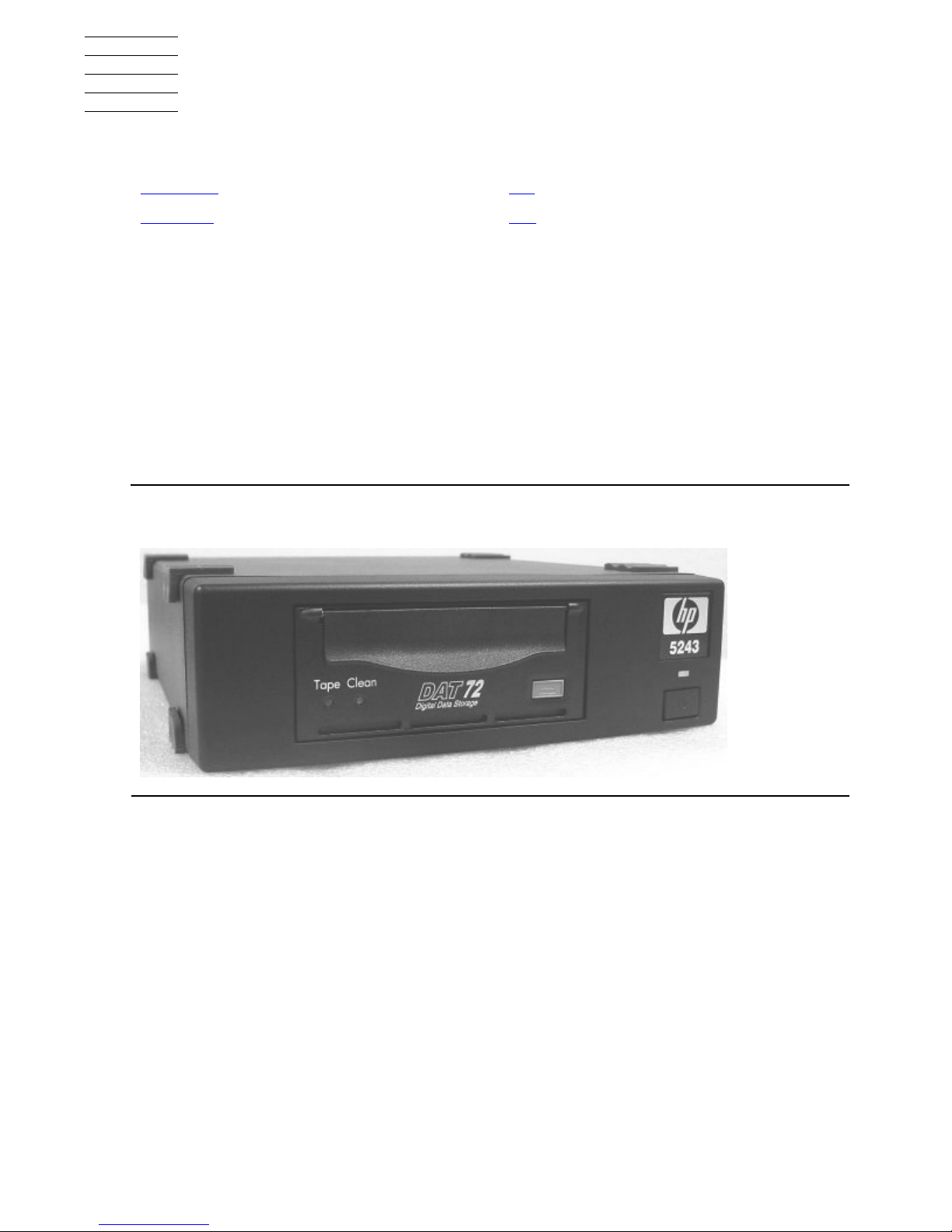
The tape drive is designed for file backup and archive applications for NonStop
servers. It comes in a tabletop configuration and has built-in power-on-self-test (POST)
diagnostics.
The tape drive uses a DAT72 drive and is designed to use a 170-meter DAT72 tape
cartridge. The tape drive is also backward compatible with the DDS-3 tape format. It is
not backward compatible with DDS-2 or DDS-1 tape formats.
Overview 1-1
Features 1-3
Figur e 1-1. Front Vi ew of Tape Drive
Page 10
Overview and Features
5243 Tape Dri ve Installation and User’s Guide—542758-003
1-2
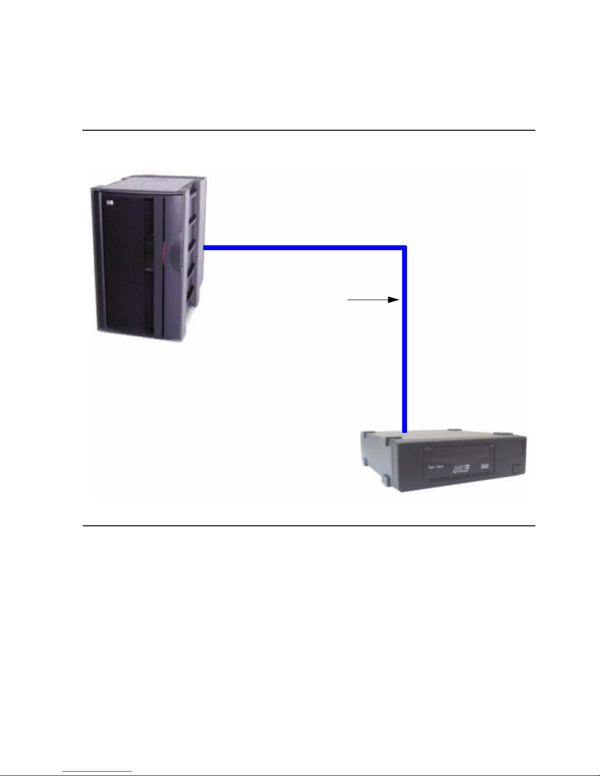
NonStop S-Series Servers
NonStop S-Series Servers
The tape drive connects to a ServerNet/DA, IOMF2 CRU, or PMF CRU on the HP
NonStop S-series server with a SCSI cable.
Figure 1-2. Configuration for the NonStop S-Series Server
SCSI Cable
Tape Drive
NonStop
S-Series
Server
Page 11
Overview and Features
5243 Tape Dri ve Installation and User’s Guide—542758-003
1-3
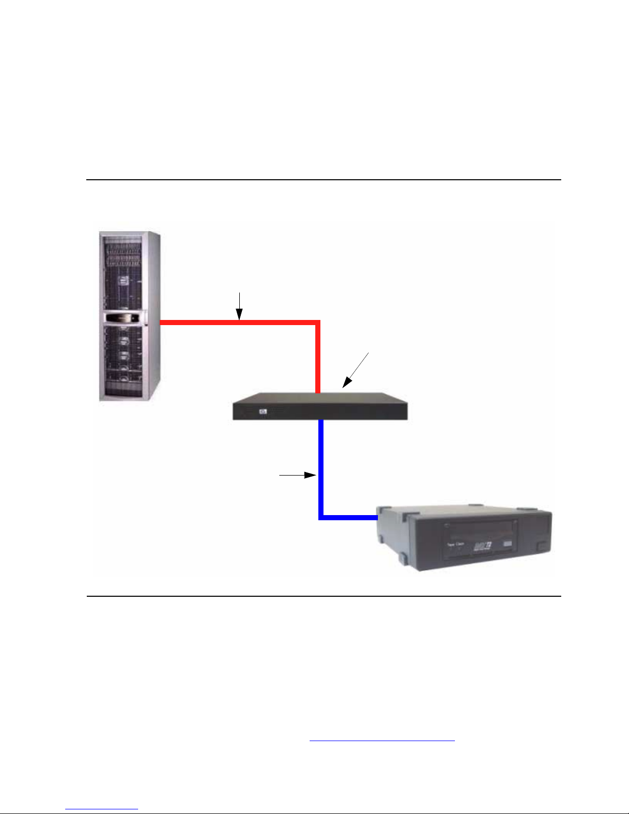
NonStop NS-Series Servers
NonStop N S- Series Servers
An M8201R Fibre Channel to SCSI router must be used to connect the tape drive to
the Fibre Channel ServerNet adapter (FCSA) on the HP Integrity NonStop NS-series
server. For more information, refer to the M8201R Fibre Channel to SCSI Router
Installation an d U ser’s Guide and the Fibre Channe l Se rver Net A dapte r In sta llati on a nd
Support Guide.
Features
The DAT72 tape drive can store 36 GB of data per DAT72 cartridge and up to 72 GB of
data in compressed mode (assuming a 2:1 compression factor). The tape drive has
both read and write heads and can perform read-after-write (RAW) data checking.
Specifications
For the tape drive specifications, refer to Appendix A, Specifications.
Figure 1-3. Configuration for the Integrity NonStop NS-Series Server
Fiber Cable
SCSI Cable
Tape Drive
NonStop
NS-Series
Server
Fibre Channel to SCSI Router
Page 12

Overview and Features
5243 Tape Dri ve Installation and User’s Guide—542758-003
1-4
Specifications
Page 13

5243 Tape Dri ve Installation and User’s Guide—542758-003
2-1
2
Installing and Configuring the Tape
Drive for the NonStop S-Series
Server
This section includes:
Installation
1. Unpack and check the shipment.
2. Choose a site for the tape drive.
3. Place the tape drive on a flat, sturdy, and level surface. The device should be
placed in an environment that is free of dust and humidity.
Installation 2-1
Configuration 2-4
Figure 2-1. Front View of Tape Drive
Power Switch
Page 14

Installing and Configuring the Tape Drive for the
NonStop S-Series Server
5243 Tape Dri ve Installation and User’s Guide—542758-003
2-2
Installation
4. Connect one end of the SCSI cable to the top SCSI port at the rear of the tape
drive. See Figure 2-2 for the location.
5. Hand tighten the screws to secure the cable to the unit.
6. Connect the opposite end of the SCSI cable to the NonStop S-series server.
The tape drive can connect to the ServerNet/DA, IOMF2 CRU, or PMF CRU on
the NonStop S-series server.
You can use any of the SCSI cables listed in Table 2-1.
7. Place a terminator on the bottom SCSI port of the tape drive.
8. Check that the power button on the front of the tape drive is off.
9. Connect the power cord to the AC power receptacle on the rear of the tape drive.
Check that the power cord is fully seated.
Note. The t ape drive’s SCSI ID co m es preconfigured to SCSI ID 5. If you nee d to ch ange
the SCS I ID, use a screwdriver. Do not use a lead p encil.
Figure 2-2. Rear View of Tape Drive
Table 2-1. SCSI Cables
Model Number Description
519-003W 3 meter copper SCSI cable
519-015W 15 meter copper SCSI cable
519-020W 20 meter copper SCSI cable
519-023W 23 meter copper SCSI cable
AC Power Receptacle Fan SCSI Ports SCSI ID
Page 15

Installing and Configuring the Tape Drive for the
NonStop S-Series Server
5243 Tape Dri ve Installation and User’s Guide—542758-003
2-3
Installation
10. Connect the other end of the power cord to a nearby AC power outlet.
11. Power on the tape drive by pressing the power switch on the front of the unit. For
the location, see Figure 2-1 on page 2-1.
Note. The tape drive does not have protection against lightning surges. Customers in high-risk
areas sho uld use exte rnal surge pr ot ec t ion rated for us e in their location and be able to hand le
the powe r demand of th e tap e drive.
Page 16

Installing and Configuring the Tape Drive for the
NonStop S-Series Server
5243 Tape Dri ve Installation and User’s Guide—542758-003
2-4
Configuration
Configuration
ServerNet/DA
To add the tape drive to the server configuration database, use the SCF ADD TAPE
command. Before issuing this command, check that the tape drive is installed properly.
To add the tape drive:
-> SCF
-> ADD TAPE $DAT72, SENDTO STORAGE, LOCATION (1,1,51), SAC
1, DEVICEID 5, PRIMARYCPU 0, BACKUPCPU 1
-> START TAPE $DAT72
-> STATUS TAPE $DAT72, DETAIL
For complete details about the ADD and STATUS commands, including
command syntax, see the SCF Reference Manual for the Storage Subsystem.
PMF CRU
To add the tape drive to the server configuration database, use the SCF ADD TAPE
command. Before issuing this command, check that the tape drive is installed properly.
To add the tape drive:
-> SCF
-> ADD TAPE $DAT72, SENDTO STORAGE, LOCATION (1,1,50),
DEVICEID 5, PRIMARYCPU 0, BACKUPCPU 1
-> START TAPE $DAT72
-> STATUS TAPE $DAT72, DETAIL
In this example:
•
The LOCATION attribute specifies the location (group, module, and slot) of
the PMF CRU (adapter) to which the tape drive is attached.
•
The DEVICEID attribute shows the device ID that is configured for the
device. This ID must match the SCSI ID that is physically set in the device.
•
The PRIMARYCPU attribute specifies the processor in which the primary
tape process should execute.
•
The BACKUPCPU attribute specifies the processor in which the tape
process starts its backup process.
For more information about the ADD and STATUS commands, see the SCF
Reference Manual for the Storage Subsystem.
Page 17

5243 Tape Dri ve Installation and User’s Guide—542758-003
3-1
3 Operation
This section includes:
Front Panel
Front Panel 3-1
Loading and Unloading Tape Cartridges 3-3
Using Correct Media 3-5
Figure 3-1. Front View of Tape Drive
1 2 3 4 5
1. Tape LED
2. Clean LED
3. Cartridge Door
4. Eject Button
5. Power Switch
Page 18

Operation
5243 Tape Dri ve Installation and User’s Guide—542758-003
3-2
Front Panel
There are two LEDs, labeled Tape and Clean. Table 3-1 shows the meaning of
different patterns of LEDs.
Table 3-1. Tape Drive LEDs
Tape LED Clean LED Meaning
On Off The cartridge is loa ded, and the ta pe drive is
ready.
Flashing
Slowly
Off The cartridge is loa ding or unloading, or self -
test is in prog ress.
Flashing
Rapidly
Off The cartridge is loa ded, and act iv it y is
occurring.
Off or
Flashing
On This is the Error Condition Signal. The tape
drive perfo rm ed a comprehensive s elf-test
during po w er-up. If a hard error causes th e s elftest to fail, the clean light changes to steady
amber.
Off or
Flashing
Flashing
Slowly
This is the Media Caution Signal.
1. Wait for the current operation to finish.
Then ins ert a different tape and repeat the
operation that was being perf orm ed.
2. If the Media Caution Signal does not
appear this time, it indicates that the
original cartridge was nearing the end of its
useful life. Copy any data you want to keep
from the original tape onto a new tape if
possibl e. T hen discard t he old tape.
3. If the Media Caution Signal appears again
with the s ec ond tape, the tape heads ne ed
cleaning.
4. If the Media Caution Signal appear s after
using a cleaning cartridge, the cleaning
cartridg e has proba bly ex pired and s hould
be discarded.
Flashing
Slowly
Flashing
Slowly
When the two LEDs flash alternately, the tape
drive is in disaster recovery mode.
Page 19

Operation
5243 Tape Dri ve Installation and User’s Guide—542758-003
3-3
Loading and Unloading Tape Cartri dges
Loading and Unloading Tape Cartridges
Inser ting Tape Ca r tr idges
1. Insert a cartridge into the slot on the front panel. As the cartridge is inserted, the
tape drive takes it and performs a load sequence.
2. The Tape light flashes green while the tape drive performs its load sequence.
When the cartridge is loaded, the Tape light shows steady green.
Figure 3-2. Inserting a Tape Cartridge
1
2
1. Cartridge Door
2. Arrow Indicates Leading Direction
Page 20

Operation
5243 Tape Dri ve Installation and User’s Guide—542758-003
3-4
Removing Tape Car t ri dges
Removing Tape Cartridges
1. Press the Eject button on the front panel.
2. The tape drive completes any task it is currently performing, winds the tape to the
beginning, and ejects the cartridge. The sequence takes about 25 seconds for a
write-enabled cartridge and 10 seconds for a write-protected cartridge.
Caution. Never try to remove a tape cartridge before it is fully ejec t ed.
Figure 3-3. E jecting a Cartridge
Caution. To ens ure reliable operation, do not remove power from the tape drive during read,
write, f as t-search, load, and unload ac t ivities .
Eject Button
Page 21

Operation
5243 Tape Dri ve Installation and User’s Guide—542758-003
3-5
Using Correct Media
Using Correct Media
For best performance, use media from HP.
Data Cartridges
The tape drive is fully backward compatible, but old tape formats are more abrasive
than more recent ones. Using older tape formats can reduce the life expectancy of the
tape dr ive. Table 3-2 summarizes the co mp atibility b etween t ape d rive models and tape
cartridges.
*Capacities assume a compression ration of 2:1.
Table 3-2. Data Cartridge Compatibility
DDS-2
120 mete r
DDS-3
125 meter
DDS- 4 150
meter
DA T 72
170 mete r
Not
supported
Read/write Read/write 72GB*
C8010A
Note. The ta pe drive does not support DDS-1 car t ridges.
Page 22

Operation
5243 Tape Dri ve Installation and User’s Guide—542758-003
3-6
Write-Protecting Cartridges
Write-Protecting Cartridges
If you want to protect the data on a cartridge from being altered or overwritten, you can
write-protect the cartridge.
Always remove the cartridge from the tape drive before you change the write
protection:
•
To write-protect a cartridge, slide the tab on the rear of the cartridge so that the
recognition hole is open.
•
To write-enable a cartridge, slide the tab back so that the hole is closed.
Figure 3-4. Write-Protecting a Cartridge
Note. Writ e-protect ion will not prot ect your cartridges against ma gnets (or bulk era s ers ).
1 2
1. Tab Closed, Cartridge Write-Enabled
2. Tab Open, Cartridge Write-Protected
Page 23

Operation
5243 Tape Dri ve Installation and User’s Guide—542758-003
3-7
Cleaning Tape C ar t ri dges
Cleaning Tape Cartridges
HP recommends cleaning the tape drive weekly using a cleaning cartridge. Do not use
swabs or other means to clean the heads. The cleaning cartridge uses a special tape
to clean the tape heads. A cleaning cartridge can only be used 50 times or as
instructed on the cartridge packaging. Always place a check mark in a box each time
you use the cartridge to clean the tape drive. Replace the cleaning cartridge when all
the boxes are checked.
1. Insert a cleaning cartridge into the tape drive. The tape drive automatically loads
the cartridge and cleans the heads.
At the end of the cleaning cycle, the tape drive ejects the cartridge. The cleaning
cycle takes approximately 30 to 60 seconds.
If the cleaning cartridge is not ejected, it has probably expired. In that case, press
the Eject button, discard the cleaning cartridge and repeat the operation with a
new one.
2. Remove the cleaning cartridge from the tape drive.
Handling Tape Cartri dge s
•
Do not touch the tape media.
•
Do not attempt to clean the tape path or tape guides inside the cartridge.
•
Do not leave cartridges in excessively dry or humid conditions. Do not leave
cartridges in direct sunlight or in places where magnetic fields are present (for
example, under telephones, next to monitors, or near transformers).
•
Do not drop cartridges or handle them roughly.
•
Do not stick more than one label onto the cartridge label area; extra labels can
cause the cartridges to jam in the tape drive. Stick labels onto the label area only.
•
For storage conditions, see the insert included with the tape cartridge .
Page 24

Operation
5243 Tape Dri ve Installation and User’s Guide—542758-003
3-8
Handling Ta pe Cartridges
Page 25

5243 Tape Dri ve Installation and User’s Guide—542758-003
4-1
4 Troubleshooting
The first step in problem-solving is establishing whether the problem lies with the tape
cartridge, the tape drive, or the server and its connections. If a problem occurs with the
tape drive or the server and its connections, refer to the steps in Section 2, Installing
and Configuring the Tape Drive for the NonStop S-Series Server, to make sure that
everything was installed and connected correctly.
Problems With Tape Cartridges
•
Check that the tape cartridge case is intact and that it contains no splits, cracks, or
damage.
•
Check that the tape cartridge has been stored at the correct temperature and
humidity. This prevents condensation. For storage conditions, see the insert
included with the tape cartridge.
•
Check that the write-protect switch is fully operational. It should move from side to
side with a positive click.
The Tape Cartridge Is Jammed
If the tape cartridge is jammed or the backup application is unable to eject it, you can
force eject the tape cartridge.
1. Press and hold the Eject button on the front of the tape drive for at least 15
seconds, or press the Eject button three times within 5 minutes.
2. Wait for the cartridge to be ejected. To give the normal eject procedure a chance to
proceed, the tape drive waits until 35 seconds have passed from the time of the
first press. After this period, it immediately releases the tape and ejects it
regardless of what operation it was performing. It is important that you allow
sufficient time for the tape drive to complete this process. If you interrupt it, you
might damage the media or the tape drive.
The tape drive is then reset as though you had turned the power off and then on
again.
3. You might lose data if you force eject a tape cartridge. The tape could also become
unreadable because an EOD (End of Data) mark might not be properly written.
Page 26

Troubleshooting
5243 Tape Dri ve Installation and User’s Guide—542758-003
4-2
The Tape Drive Will Not Accept the Tape Cartridge
(or Ejects It Immediately)
The Tape Drive Will Not Accept the Tape Cartridge (or Ejects It
Immediately)
The tape cartri dge migh t have been da mage d (drop ped, for ex ample) , or the t ape driv e
might have a fault. If it is a cleaning cartridge, it has probably expired and should be
discarded immediately. For data cartridges:
1. Check that the tape drive has power, the power cable is properly connected, and
the Tape LED is on.
2. Check that you are using the correct media for the tape drive.
3. Check that you have loaded the tape cartridge with the correct orientation.
4. Check for damage to your media and discard it if it is damaged.
5. Use a new piece of media or one known to be good, and see if it loads. If it does,
the original cartridge is faulty and should be discarded.
6. Check if another DAT drive of the same model will accept the tape cartridge. If it
does, the original tape drive might be faulty.
Page 27

5243 Tape Dri ve Installation and User’s Guide—542758-003
A-1
A Specifications
This appendix provides specifications for the tape drive.
Weight of Tape Drive Components
This table lists the weight of the tape drive and cartridges.
Figure A-1. Tape Drive Dimensions
Table A-1. Weight of Tape Drive Components
Component Weight
Tape drive 5 pound s (2. 27 kilograms )
DAT 72 tape cartridge 1.1 ounc es (31.2 grams ) with case
0.5 ounc es (14.2 grams ) without cas e
1. Length - 10 inches (25.4 centimeters)
2. Width - 8 inches (20.3 centimeters)
3. Height - 2.5 inches (6.4 centimeters)
2
1
3
Page 28

Specifications
5243 Tape Dri ve Installation and User’s Guide—542758-003
A-2
Tec hnical Specif ications
Technical Speci fications
Capacity
Performance
Media
Tape Format
Native 36 gigabytes
Compressed (assumes
2:1 data compression)
72 gigabytes
Buffer Size 8 megabytes
Sustained Transfer Rate
(native)
3.2 megabytes/second
Sustained Transfer Rate
(with 2:1 data compression)
6.4 megabytes/second
Data Access Time 68 seconds
Average Load Time 15 seconds
Average Unload Time 15 seconds
Rewind Time 120 seconds (end to end)
Rewind Tape Speed 1.41 meters/second
MTBF 125,000 hours at 100% duty cycle
Recommended Media DAT 72 (170 meters)
Recording Method 4 millimeter helical scan
Recording Format DAT 72, DDS-4, DDS-3
Data Compression Lempel-Ziv (DCLZ)
Page 29

Specifications
5243 Tape Dri ve Installation and User’s Guide—542758-003
A-3
Power Specifications
Power Specifications
Power Requirements
•
100 to 240 V ac
•
50/60 Hertz
Environmental Specifications
Relative Humidity Storage 5% to 95%
Operating 20% to 80%
Temperature Range Storage -40 degre es to 158 de grees Fahr enheit
(-40 degrees to 70 degrees Celsius)
Operating -41 degrees to 158 de grees Fahr enhei t
(-40 degrees to 70 degrees Celsius)
Page 30

Specifications
5243 Tape Dri ve Installation and User’s Guide—542758-003
A-4
Environmental Specifications
Page 31

5243 Tape Dri ve Installation and User’s Guide—542758-003
Statements-1
Safety and Compliance
This sections contains three types of required safety and compliance statements:
•
Regulatory compliance
•
Waste Electrical and Electronic Equipment (WEEE)
•
Safety
Regulatory Compliance Statements
The following regulatory compliance statements apply to the products documented by
this manual.
FCC Compliance
This equipment has been tested and found to comply with the limits for a Class A
digital device, pursuant to part 15 of the FCC Rules. These limits are designed to
provide reasonable protection against harmful interference when the equipment is
operated in a commercial environment. This equipment generates, uses, and can
radiate radio-frequency energy and, if not installed and used in accordance with the
instruction manual, may cause interference to radio communications. Operation of this
equipment in a residenti al area is likely to cause harm ful interfer ence in wh ich case the
user will be required to correct the interference at his own expense.
Any changes or modifications not expressly approved by Hewlett-Packard Computer
Corporation could void the user’s authority to operate this equipment.
Canadian Compliance
This class A digital apparatus meets all the requirements of the Canadian InterferenceCausing Equipment Regulations.
Cet appare il numér i que d e la classe A r especte toutes le s exigence s du R ège lment sur
le matériel brouilleur du Canada.
Page 32

Safety and Compliance
5243 Tape Dri ve Installation and User’s Guide—542758-003
Statements-2
Regulatory Compliance Statements
Korea MIC Compliance
Taiwan (BSMI) Compliance
Japan (VCCI) Compliance
This is a Class A product based on the standard or the Voluntary Control Council for
Interference by Information Technology Equipment (VCCI). If this equipment is used in
a domestic environment, radio disturbance may occur, in which case the user may be
required to take corrective actions.
Page 33

Safety and Compliance
5243 Tape Dri ve Installation and User’s Guide—542758-003
Statements-3
Waste Electrical and Electronic Equipment (WEEE)
European Union Notice
Products with the CE Marking comply with both the EMC Directive (89/336/EEC) and
the Low Voltage Directive (73/23/EEC) issued by the Commission of the European
Community.
Compliance with these directives implies conformity to the following European Norms
(the equivalent international standards are in parenthesis):
•
EN55022 (CISPR 22)—Electromagnetic Interference
•
EN55024 (IEC61000-4-2, 3, 4, 5, 6, 8, 11)—Electromagnetic Immunity
•
EN61000-3-2 (IEC61000-3-2)—Power Line Harmonics
•
EN61000-3-3 (IEC61000-3-3)—Power Line Flicker
•
EN60950-1 (IEC60950-1)—Product Safety
HIGH LEAKAGE CURRENT
To reduce the risk of electric shock due to high leakage currents, a reliable grounded
(earthed) connection should be checked before servicing the power distribution unit
(PDU).
Observe the following limits when connecting the product to AC power distribution
devices: For PDUs that have attached AC power cords or are directly wired to the
building power, the total combined leakage current should not exceed 5 percent of the
rated input current for the device.
“HIGH LEAKAGE CURRENT, EARTH CONNECTION ESSENTIAL BEFORE
CONNECTING SUPPLY”
“HOHER ABLEITSTROM. VOR INBETRIEBNAHME UNBEDINGT
ERDUNGSVERBINDUNG HERSTELLEN”
“COURANT DE FUITE E’LEVE’. RACCORDEMENT A LA TERRE INDISPENSABLE
AVANT LE RACCORDEMENT AU RESEAU”
Waste Electrical and Electronic Equipment
(WEEE)
Information about the Waste Electrical and Electronic Equipment (WEEE) directive is
available from the NonStop Technical Library (NTL) home page. Select Safety and
Compliance > Waste Electrical and Electronic Equipment (WEEE).
Page 34

Safety and Compliance
5243 Tape Dri ve Installation and User’s Guide—542758-003
Statements-4
Important Safety Information
Important Safety Information
Safety information is available from the NTL home page. Select Safety and
Compliance > Important Safety Information. To open the safety information in a
language other than English, select the language. Local HP support can also help
direct you to your safety information.
Page 35

Safety and Compliance
5243 Tape Dri ve Installation and User’s Guide—542758-003
Statements-5
Declaration of Conformity
Declaration of Conformity
The undersigned authority declares that the product listed below
and manufactured at the following manufacturing location
Tributary Systems, Inc.
3717 Commerce Place Suite C
Bedford, Texas 76021
U.S.A.
Conforms to the following normative European and International Standards:
Normative Standards:
EN 55022:1998 "Em issions for In form ation Technol ogy Equipm ent"
EN 55024:1998 "Immuni ty for Informa tion Technology E quipment"
EN 60950-1:2001 "Safety of Information Technology Equipment"
Following the provisions of the normative European Council Directives
EMC directive 89/336/EEC (including amendments)
Low Voltage Directive 72/23/EEC (amended by 93/68/EEC)
For Regulatory Compliance Information Only, contact:
Tributary Systems, Inc. Phone: 817-354-8009
Attn: Product Compliance Email: support@tributary .com
3717 Commerce Place Suite C
Bedford, Texas 76021
Date: March 13, 2006
PRODUCT TYPE DAT72 Tabletop Tape Drive
MODEL NUMBERS HP 5243
INTERFACES SCSI
Kevin St. Cyr
Director of En gineering
Tributary Systems, Inc.
Page 36

Safety and Compliance
5243 Tape Dri ve Installation and User’s Guide—542758-003
Statements-6
Declaration of Conformity
Page 37

5243 Tape Dri ve Installation and User’s Guide—542758-003
Index -1
Index
C
Configuration
PMF CRU 2-4
ServerNet/DA 2-4
F
Fibre Channel ServerNet adapter 1-3
Fibre Channel to SCSI router 1-3
L
Light emitting diodes 3-2
N
NonStop NS-series server 1-3
NonStop S-series server 1-2, 2-2
S
SCSI cables 2-2
ServerNet D/A 2-4
Specifications
dimensions A-1
environmental A-3
power A-3
technical A-2
T
Tape cartridges 3-5
cleaning 3-7
ejecting 3-4
handling 3-7
inserting 3-3
problems 4-1
write protecting 3-6
Troubleshooting 4-1
Page 38

Index
5243 Tape Dri ve Installation and User’s Guide—542758-003
Index -2
T
 Loading...