

Page 1
HP LaserJet 5200/5200L Series printers
Service Manual
Page 2

Page 3

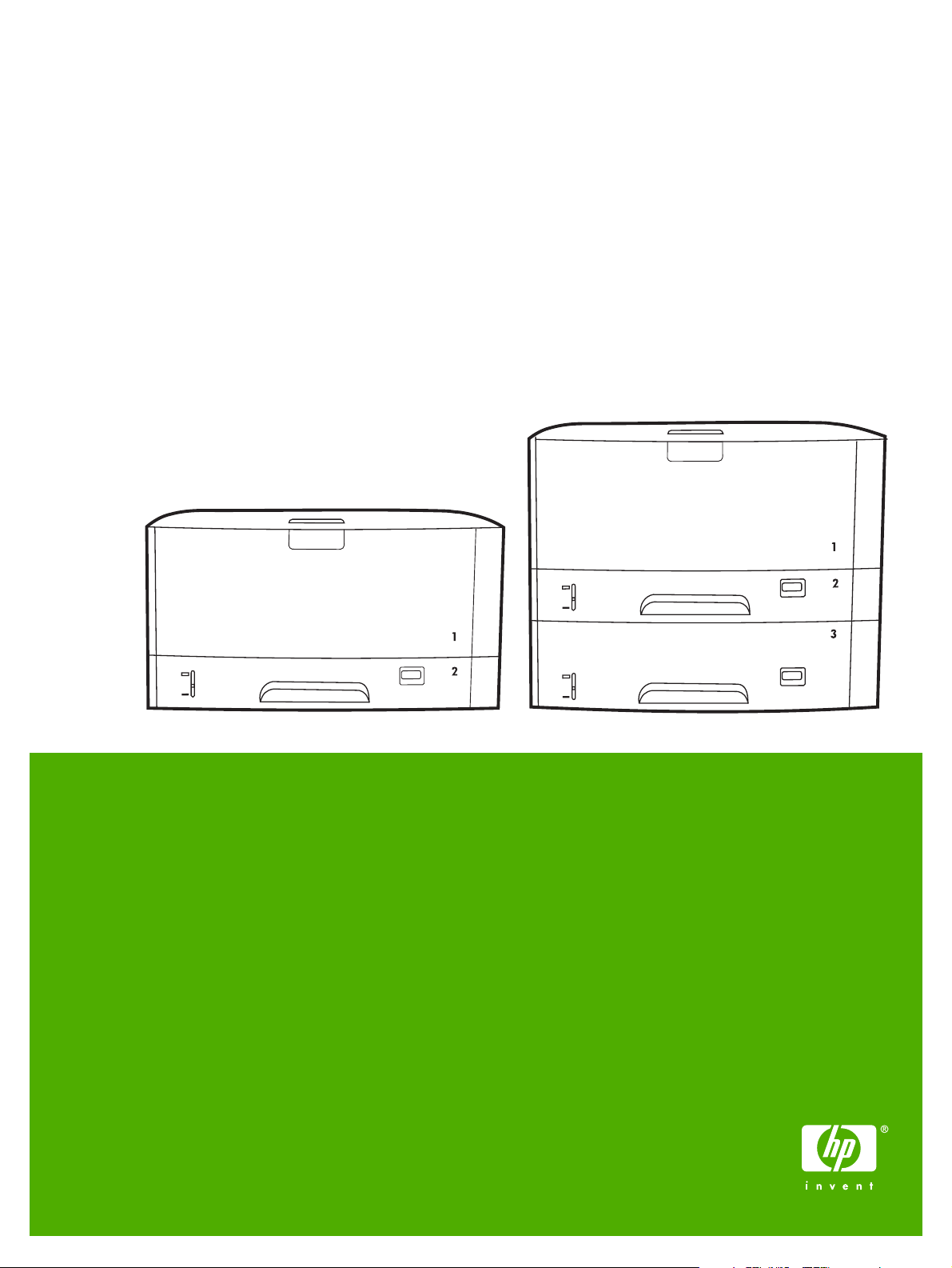
HP LaserJet 5200 Series printers
Service Manual
Page 4

Copyright and license
Trademark credits
© 2006 Copyright Hewlett-Packard
Development Company, L.P.
Reproduction, adaptation, or translation
without prior written permission is prohibited,
except as allowed under the copyright laws.
The information contained herein is subject
to change without notice.
The only warranties for HP products and
services are set forth in the express warranty
statements accompanying such products
and services. Nothing herein should be
construed as constituting an additional
warranty. HP shall not be liable for technical
or editorial errors or omissions contained
herein.
Edition 1, 3/2006
Part number Q7543-90934
Microsoft®, Windows®, and Windows NT®
are U.S. registered trademarks of Microsoft
Corporation.
Linux is a U.S. registered trademark of Linus
Torvalds.
PostScript® is a trademarks of Adobe
Systems Incorporated.
UNIX® is a registered trademark of The
Open Group.
Energy Star® and the Energy Star® logo are
U.S. registered marks of the United States
Environmental Protection Agency.
Page 5

Table of contents
1 Product information
Quick access to printer information ...................................................................................................... 2
Printers at a glance .............................................................................................................................. 3
HP LaserJet 5200 Series printers ........................................................................................ 3
Features at a glance ............................................................................................................................. 4
Walkaround .......................................................................................................................................... 6
Control-panel overview ......................................................................................................................... 8
Printer software .................................................................................................................................. 10
Printer drivers .................................................................................................................... 10
Driver Autoconfiguration .................................................................................... 10
Update Now ...................................................................................................... 11
HP Driver Preconfiguration ............................................................................... 11
Additional drivers ............................................................................................................... 11
Opening the printer drivers ................................................................................................ 12
Software for Macintosh computers .................................................................................... 12
Installing Macintosh printing system software for networks .............................. 13
Installing Macintosh printing system software for direct connections
(USB) ................................................................................................................ 13
To remove software from Macintosh operating systems ................................... 14
Software for networks ........................................................................................................ 14
HP Web Jetadmin ............................................................................................. 14
UNIX .................................................................................................................. 14
Linux .................................................................................................................. 15
Utilities ............................................................................................................................... 15
HP Easy Printer Care Software ......................................................................... 15
Embedded Web server ..................................................................................... 15
Other components and utilities .......................................................................... 15
Selecting print media .......................................................................................................................... 16
Supported media sizes ...................................................................................................... 16
Supported media types ...................................................................................................... 18
2 Installation and configuration
What is in the box ............................................................................................................................... 20
Identification ....................................................................................................................................... 21
Model and serial numbers ................................................................................................. 21
Site requirements ............................................................................................................................... 22
Physical specifications ....................................................................................................... 22
Space requirements ........................................................................................................... 22
Input/Output (I/O) configuration .......................................................................................................... 23
ENWW iii
Page 6

Parallel configuration ......................................................................................................... 23
USB configuration .............................................................................................................. 23
Connecting the USB cable ................................................................................ 23
Network configuration ........................................................................................................ 24
Manually configuring TCP/IP parameters from the control panel ...................... 24
Setting an IP address ....................................................................... 24
Setting the subnet mask ................................................................... 25
Setting the default gateway .............................................................. 25
Disabling network protocols (optional) .............................................................. 26
To enable or disable IPX/SPX .......................................................... 26
To enable or disable AppleTalk ........................................................ 26
To disable DLC/LLC ......................................................................... 27
Enhanced I/O (EIO) configuration ..................................................................... 27
HP Jetdirect EIO print servers .......................................................... 27
Connecting to a network or a computer ............................................................................. 27
Installing printer memory .................................................................................................................... 30
To install printer memory ................................................................................................... 30
Checking DIMM installation ............................................................................................... 34
Installing CompactFlash cards ........................................................................................................... 35
Checking CompactFlash installation .................................................................................................. 39
Enabling memory (Windows only) ...................................................................................................... 40
3 Maintenance
Managing supplies ............................................................................................................................. 42
Replacing supplies and parts ............................................................................................................. 44
Cleaning the printer ............................................................................................................................ 48
Approximate print-cartridge replacement intervals ............................................................ 42
Managing the print cartridge .............................................................................................. 42
Print-cartridge life expectancy ........................................................................... 42
Print-cartridge storage ....................................................................................... 42
HP print cartridges ............................................................................................ 42
HP policy on non-HP print cartridges ................................................................ 42
Print-cartridge authentication ............................................................................ 43
HP fraud hotline and Web site .......................................................................... 43
Checking supply levels ...................................................................................................... 43
To check supplies by using the control panel ................................................... 43
To check supplies by using HP Web Jetadmin ................................................. 43
To check supplies using the embedded Web server ........................................ 43
Supply replacement guidelines .......................................................................................... 44
Life expectancy of consumable parts ................................................................................ 44
Changing the print cartridge .............................................................................................. 44
To change the print cartridge ............................................................................ 45
Cleaning the printer manually ............................................................................................ 49
Cleaning the paper path using the printer control panel .................................................... 49
Cleaning spilled toner ........................................................................................................ 50
Vacuum specifications ...................................................................................... 50
4 Theory of operation
Engine control system ........................................................................................................................ 52
Power-on sequence ........................................................................................................... 53
iv ENWW
Page 7

Motors, fans, and solenoids ............................................................................................... 53
Laser/scanner system ........................................................................................................................ 55
Pickup-and-feed-system ..................................................................................................................... 56
Cassette (tray 2) pickup mechanism ................................................................................. 57
Multipurpose-tray (tray 1) pickup mechanism .................................................................... 58
Jam detection .................................................................................................................... 58
Image-formation system ..................................................................................................................... 59
Image-formation process ................................................................................................... 60
Latent-image formation block ............................................................................................ 60
Step 1: primary charging ................................................................................... 60
Step 2: laser-beam exposure ............................................................................ 61
Development block ............................................................................................................ 61
Step 3: developing ............................................................................................ 61
Transfer block .................................................................................................................... 61
Step 4: image transfer ....................................................................................... 61
Step 5: separation from the drum ...................................................................... 62
Fixing block ........................................................................................................................ 62
Step 6: fusing .................................................................................................... 62
Drum-cleaning block .......................................................................................................... 62
Step 7: drum cleaning ....................................................................................... 62
Print cartridge .................................................................................................................... 63
Print-cartridge activation .................................................................................................... 63
5 Removal and replacement
Removal and replacement strategy .................................................................................................... 66
Introduction ........................................................................................................................ 66
Required tools .................................................................................................................... 66
Types of screws ................................................................................................................. 67
Service approach ............................................................................................................... 67
Before performing service .................................................................................................. 68
After performing service ..................................................................................................... 68
Parts removal order ........................................................................................................... 68
Customer self-repair parts .................................................................................................................. 70
Tray 1 pickup roller ............................................................................................................ 70
Tray 2 pickup roller ............................................................................................................ 72
Tray 2 separation pad ........................................................................................................ 73
Tray 3 retard roller ............................................................................................................. 74
Tray 3 pickup and feed rollers ........................................................................................... 75
Formatter ........................................................................................................................... 76
CompactFlash cards .......................................................................................................... 77
DIMMs ............................................................................................................................... 80
Control-panel overlay ......................................................................................................... 84
Duplexer ............................................................................................................................ 84
External doors, covers, and panels .................................................................................................... 86
Right cover ......................................................................................................................... 86
Lower back cover ............................................................................................................... 86
Face-up bin ........................................................................................................................ 87
Top cover ........................................................................................................................... 89
Left cover ........................................................................................................................... 92
Left front cover ................................................................................................................... 94
ENWW v
Page 8

Face-down cover ............................................................................................................... 95
Tray 2 ................................................................................................................................. 96
Right front cover ................................................................................................................ 96
Right lower cover ............................................................................................................... 97
DC controller cover .......................................................................................................... 100
Cartridge door unit ........................................................................................................... 100
Control panel ................................................................................................................... 108
Internal assemblies .......................................................................................................................... 110
Laser/scanner .................................................................................................................. 11 0
Formatter ......................................................................................................................... 111
Fuser ................................................................................................................................ 112
Cassette-paper pickup unit .............................................................................................. 113
Face-down delivery unit ................................................................................................... 118
Main motor ....................................................................................................................... 120
Fuser motor ..................................................................................................................... 125
Main fan ........................................................................................................................... 126
Sub fan ............................................................................................................................ 129
Registration unit ............................................................................................................... 134
Transfer roller .................................................................................................................. 135
Paper-feed unit ................................................................................................................ 136
Printed circuit assemblies (PCAs) .................................................................................................... 139
DC controller .................................................................................................................... 139
High-voltage power supply .............................................................................................. 142
Low-voltage power supply PCA ....................................................................................... 151
Duplexer ........................................................................................................................................... 155
Duplexer .......................................................................................................................... 155
Duplexer left cover ........................................................................................................... 156
Duplexer right cover ......................................................................................................... 157
Duplexer top cover ........................................................................................................... 158
Duplexer back cover ........................................................................................................ 159
Duplexer feed motor ........................................................................................................ 161
Duplexer fan .................................................................................................................... 164
Duplexer PCA .................................................................................................................. 167
500-sheet feeder .............................................................................................................................. 169
500-sheet feeder front cover ............................................................................................ 169
500-sheet feeder left front cover ...................................................................................... 170
500-sheet feeder left cover .............................................................................................. 170
500-sheet feeder right front cover .................................................................................... 172
500-sheet feeder right cover ............................................................................................ 173
500-sheet feeder rear dust cover ..................................................................................... 175
500-sheet feeder paper-pickup unit ................................................................................. 176
500-sheet feeder lifter drive unit ...................................................................................... 180
500-sheet feeder drive unit .............................................................................................. 182
500-sheet feeder drive PCA ............................................................................................ 186
500-sheet feeder pickup motor ........................................................................................ 186
6 Troubleshooting
Introduction ....................................................................................................................................... 191
Basic troubleshooting checklist ........................................................................................................ 192
Factors that affect printer performance ............................................................................ 192
vi ENWW
Page 9

Troubleshooting flowchart ................................................................................................................ 193
Step 1: Does READY appear on the control-panel display? ........................................... 193
Step 2: Can you print a configuration page? ................................................................... 193
Step 3: Can you print from a program? .......................................................................... 194
Step 4: Does the job print as expected? .......................................................................... 195
Step 5: Does the printer select the trays? ........................................................................ 196
Solving general printing problems .................................................................................................... 198
Control-panel message types ........................................................................................................... 201
Control-panel messages .................................................................................................................. 202
Replacement-parts configuration ..................................................................................................... 220
Formatter and DC controller ............................................................................................ 220
Formatter (new) ............................................................................................................... 220
DC controller (new or previously installed in another printer) .......................................... 220
Formatter ......................................................................................................................... 220
Guidelines for using paper ............................................................................................................... 221
Printing special pages ...................................................................................................................... 222
Data collection .................................................................................................................................. 223
General paper-path troubleshooting ................................................................................................. 224
Paper-path checklist ........................................................................................................ 224
Jams in tray 1 .................................................................................................................. 225
Jams in tray 2 or the optional 500-sheet feeder .............................................................. 225
Common causes of jams .................................................................................................................. 226
Jam locations ................................................................................................................................... 227
Jam recovery ................................................................................................................... 229
Clearing jams ................................................................................................................................... 230
Clearing jams from the input-tray areas ........................................................................... 230
Clearing jams from the print-cartridge area ..................................................................... 231
Clearing jams from the output-bin areas .......................................................................... 233
Clearing jams from the optional duplexer ........................................................................ 235
Solving repeated jams ..................................................................................................... 236
Troubleshooting print-quality problems ............................................................................................ 238
Print-quality problems associated with media .................................................................. 238
Print-quality problems associated with the environment .................................................. 238
Print-quality problems associated with jams .................................................................... 238
Image-defect examples ................................................................................................... 238
Light print (partial page) .................................................................................................. 240
Light print (entire page) .................................................................................................... 240
Specks ............................................................................................................................. 241
Dropouts .......................................................................................................................... 241
Lines ................................................................................................................................ 242
Gray background ............................................................................................................. 242
Toner smear .................................................................................................................... 243
Loose toner ...................................................................................................................... 243
Repeating defects ............................................................................................................ 244
Repeating image .............................................................................................................. 244
Misformed characters ...................................................................................................... 244
Page skew ....................................................................................................................... 245
Curl or wave ..................................................................................................................... 245
Wrinkles or creases ........................................................................................................ 246
Vertical white lines ........................................................................................................... 246
ENWW vii
Page 10

Tire tracks ........................................................................................................................ 247
White spots on black ....................................................................................................... 247
Scattered lines ................................................................................................................. 247
Blurred print ..................................................................................................................... 248
Random image repetition ................................................................................................ 248
Interface troubleshooting .................................................................................................................. 250
Communication checks .................................................................................................... 250
AUTOEXEC.BAT standard configurations ....................................................................... 250
Parallel MS-DOS commands .......................................................................... 250
Printer Job Language (PJL) commands .......................................................................... 250
@PJL [Enter] ................................................................................................... 250
UEL ................................................................................................................. 251
@PJL COMMENT ........................................................................................... 251
@PJL INFO CONFIG ...................................................................................... 251
@PJL INFO ID ................................................................................................ 251
@PJL INFO USTATUS ................................................................................... 251
@PJL INFO PAGECOUNT ............................................................................. 251
@PJL JOB ...................................................................................................... 251
@PJL EOJ ...................................................................................................... 252
@PJL ECHO ................................................................................................... 252
@PJL USTATUS JOB=ON/OFF ..................................................................... 252
@PJL USTATUSOFF ..................................................................................... 252
Changing printer-control-panel configuration settings ...................................................................... 253
Changing control-panel settings ...................................................................................... 253
To change a control-panel setting ................................................................... 253
Show address .................................................................................................................. 253
Tray-behavior options ...................................................................................................... 254
Sleep Delay ..................................................................................................................... 255
Personality ....................................................................................................................... 256
Clearable warnings .......................................................................................................... 256
Auto continue ................................................................................................................... 257
Cartridge low .................................................................................................................... 257
Cartridge-out response .................................................................................................... 257
Jam recovery ................................................................................................................... 258
RAM disk ......................................................................................................................... 258
Language ......................................................................................................................... 259
Fuser modes .................................................................................................................... 259
Using the control-panel menus ......................................................................................................... 261
To use the menus ............................................................................................................ 261
Show Me How menu ........................................................................................................................ 262
Retrieve Job menu .......................................................................................................................... 263
Information menu ............................................................................................................................. 264
Paper Handling menu ....................................................................................................................... 265
Configure Device menu .................................................................................................................... 266
Printing submenu ............................................................................................................. 266
Print Quality submenu ..................................................................................................... 268
System Setup submenu ................................................................................................... 271
I/O submenu .................................................................................................................... 275
Resets submenu .............................................................................................................. 276
Diagnostics menu ............................................................................................................................. 277
viii ENWW
Page 11

Service menu ................................................................................................................................... 278
Tools for troubleshooting .................................................................................................................. 279
Using the configuration page ........................................................................................... 279
Using the embedded Web server .................................................................................... 280
Accessing the embedded Web server ............................................................ 281
Information tab ................................................................................................ 281
Settings tab ..................................................................................................... 281
Setting the real-time clock ............................................................................... 282
Networking tabs .............................................................................................. 282
Other links ....................................................................................................... 282
Configuration pages ......................................................................................................... 283
Configuration page .......................................................................................... 283
HP embedded Jetdirect page .......................................................................... 283
Paper-handling configuration page ................................................................. 284
Finding important information on the configuration page ................................ 284
Print the supplies status page .......................................................................................... 285
Print the usage page ........................................................................................................ 286
Print the file directory page .............................................................................................. 288
Print the PCL font list page .............................................................................................. 289
Print the PS font list page ................................................................................................ 290
Diagnostics ....................................................................................................................................... 291
Embedded HP Jetdirect LEDs ......................................................................................... 291
Heartbeat LED ................................................................................................................. 292
Printer resets .................................................................................................................................... 293
Cold reset ........................................................................................................................ 293
To perform a cold reset ................................................................................... 293
NVRAM initialization ........................................................................................................ 293
To initialize NVRAM ........................................................................................ 294
Perform the self test ......................................................................................................... 294
Save + Restore ................................................................................................................ 294
Replacing the formatter and the DC controller ................................................ 295
Replacing the formatter only ........................................................................... 295
Replacing the DC controller only ..................................................................... 296
Service menu (service PIN codes) .................................................................................. 296
Service ID ........................................................................................................ 297
Restoring the Service ID ................................................................................. 297
Converting the Service ID to an actual date .................................................... 297
Test pages ........................................................................................................................................ 298
Engine-test page .............................................................................................................. 298
Formatter-test page ......................................................................................................... 298
Troubleshooting network printing problems ..................................................................................... 299
Troubleshooting common Windows problems ................................................................................ 300
Troubleshooting common Macintosh problems ................................................................................ 301
Troubleshooting Linux problems ...................................................................................................... 303
Troubleshooting common PostScript problems ................................................................................ 304
General problems ............................................................................................................ 304
7 Parts and diagrams
Parts ................................................................................................................................................. 310
How to use the parts lists and diagrams .......................................................................................... 311
ENWW ix
Page 12

Types of screws ............................................................................................................................... 311
Related documentation and software ............................................................................................... 312
Accessories and supplies ................................................................................................................. 312
External panels and covers .............................................................................................................. 316
Internal components ......................................................................................................................... 320
Paper-feed assembly ....................................................................................................................... 326
Face-up delivery assembly ............................................................................................................... 328
Face-down delivery assembly .......................................................................................................... 330
PCAs ................................................................................................................................................ 332
Fuser ................................................................................................................................................ 334
Cassette (tray 2) ............................................................................................................................... 336
Cassette (tray 2) paper-pickup assembly ......................................................................................... 338
500-sheet feeder cassette (tray 3) ................................................................................................... 340
500-sheet feeder, cassette, external panels and covers .................................................................. 342
500-sheet feeder internal components ............................................................................................. 344
500-sheet feeder paper-pickup assembly ........................................................................................ 346
500-sheet feeder drive assembly ..................................................................................................... 348
500-sheet feeder lifter-drive assembly ............................................................................................. 350
500-sheet feeder PCA ...................................................................................................................... 352
Duplexer ........................................................................................................................................... 354
Duplexing PCA assembly ................................................................................................................. 358
Duplexing-feed drive assembly ........................................................................................................ 360
Alphabetical parts list ....................................................................................................................... 362
Numerical parts list ........................................................................................................................... 369
Appendix A Printer specifications
Electrical specifications .................................................................................................................... 378
Power-consumption specifications ................................................................................................... 379
Acoustic specifications ..................................................................................................................... 380
Operating-environment specifications .............................................................................................. 381
Appendix B Product warranty
Hewlett-Packard Limited Warranty Statement ................................................................................. 384
Availability of support and service .................................................................................................... 385
HP maintenance agreements ........................................................................................................... 386
Next-Day Onsite Service ................................................................................................. 386
Appendix C Regulatory statements
FCC regulations ............................................................................................................................... 388
Declaration of conformity .................................................................................................................. 389
Safety statements ............................................................................................................................. 390
Laser safety ..................................................................................................................... 390
Canadian DOC regulations .............................................................................................. 390
EMI statement (Korea) ..................................................................................................... 390
VCCI statement (Japan) .................................................................................................. 390
Power cord statement (Japan) ......................................................................................... 390
Laser statement for Finland ............................................................................................. 391
Index ................................................................................................................................................................. 393
x ENWW
Page 13

List of tables
Table 1-1 Printer guides ..................................................................................................................................... 2
Table 1-2 HP LaserJet 5200 Series printer configurations ................................................................................ 3
Table 1-3 Features ............................................................................................................................................. 4
Table 2-1 Physical dimensions for the HP LaserJet 5200 Series printers ....................................................... 22
Table 4-1 Sequence of operation ..................................................................................................................... 52
Table 6-1 Causes for jams in tray 1 ............................................................................................................... 225
Table 6-2 Causes for jams in tray 2 or the optional 500-sheet feeder ........................................................... 225
Table 6-3 Fuser modes .................................................................................................................................. 259
Table 6-4 Optimize modes ............................................................................................................................. 260
Table 6-5 Important information on the configuration pages .......................................................................... 284
Table 7-1 Technical support Web sites .......................................................................................................... 312
Table 7-2 Accessories and supplies ............................................................................................................... 312
Table 7-3 External panels and covers ............................................................................................................ 317
Table 7-4 External panels and covers ............................................................................................................ 319
Table 7-5 Internal components (1 of 3) .......................................................................................................... 321
Table 7-6 Internal components (2 of 3) .......................................................................................................... 323
Table 7-7 Internal components (3 of 3) .......................................................................................................... 325
Table 7-8 Paper-feed assembly ..................................................................................................................... 327
Table 7-9 Face-up delivery assembly ............................................................................................................ 329
Table 7-10 Face-down delivery assembly ...................................................................................................... 331
Table 7-11 PCA assembly .............................................................................................................................. 333
Table 7-12 Fuser ............................................................................................................................................ 335
Table 7-13 Cassette (tray 2) ........................................................................................................................... 337
Table 7-14 Cassette (tray 2) paper-pickup assembly .................................................................................... 339
Table 7-15 500-sheet feeder cassette (tray 3) ............................................................................................... 341
Table 7-16 500-sheet feeder cassette external panels and covers ............................................................... 343
Table 7-17 500-sheet feeder internal components ........................................................................................ 345
Table 7-18 500-sheet feeder paper-pickup assembly .................................................................................... 347
Table 7-19 500-sheet feeder drive assembly ................................................................................................. 349
Table 7-20 500-sheet feeder lifter-drive assembly ......................................................................................... 351
Table 7-21 500-sheet feeder PCA ................................................................................................................. 353
Table 7-22 Duplexer ....................................................................................................................................... 355
Table 7-23 Duplexer ....................................................................................................................................... 357
Table 7-24 Duplexing PCA assembly ............................................................................................................. 359
Table 7-25 Duplexing-feed drive assembly .................................................................................................... 361
Table 7-26 Alphabetical parts list ................................................................................................................... 362
Table 7-27 Numerical parts list ....................................................................................................................... 369
Table A-1 Electrical specifications for the HP LaserJet 5200 Series printer .................................................. 378
Table A-2 Power consumption (average, in watts) ........................................................................................ 379
Table A-3 Sound power and pressure level ................................................................................................... 380
ENWW xi
Page 14

Table A-4 Operating-environment specifications ........................................................................................... 381
xii ENWW
Page 15

List of figures
Figure 1-1 Front view ......................................................................................................................................... 6
Figure 1-2 Back view .......................................................................................................................................... 7
Figure 1-3 Interface ports ................................................................................................................................... 7
Figure 1-4 Control panel buttons and lights ....................................................................................................... 8
Figure 2-1 What is in the shipping box ............................................................................................................. 20
Figure 2-2 Model and serial numbers ............................................................................................................... 21
Figure 2-3 Space requirements ........................................................................................................................ 22
Figure 2-4 Parallel configuration ...................................................................................................................... 23
Figure 2-5 Connecting the USB cable .............................................................................................................. 24
Figure 3-1 Cleaning the printer ......................................................................................................................... 48
Figure 4-1 Engine control system ..................................................................................................................... 52
Figure 4-2 Power-on sequence ........................................................................................................................ 53
Figure 4-3 Motors, fans, and solenoids (1 of 2) ............................................................................................... 53
Figure 4-4 Motors, fans, and solenoids (2 of 2) ............................................................................................... 54
Figure 4-5 Laser/scanner system ..................................................................................................................... 55
Figure 4-6 Pickup-and-feed-system ................................................................................................................. 57
Figure 4-7 Cassette (tray 2) pickup mechanism ............................................................................................... 58
Figure 4-8 Image-formation system ................................................................................................................. 59
Figure 4-9 Image-formation process ................................................................................................................ 60
Figure 4-10 Primary charging ........................................................................................................................... 60
Figure 4-11 Laser-beam exposure ................................................................................................................... 61
Figure 4-12 Image transfer ............................................................................................................................... 61
Figure 4-13 Separation from the drum ............................................................................................................. 62
Figure 4-14 Fusing ........................................................................................................................................... 62
Figure 4-15 Print cartridge ................................................................................................................................ 63
Figure 5-1 Screwdrivers ................................................................................................................................... 66
Figure 5-2 Parts removal order ........................................................................................................................ 69
Figure 5-3 Removing the tray 1 pickup roller (1 of 3) ....................................................................................... 70
Figure 5-4 Removing the tray 1 pickup roller (2 of 3) ....................................................................................... 71
Figure 5-5 Removing the tray 1 pickup roller (3 of 3) ....................................................................................... 71
Figure 5-6 Removing the tray 2 pickup roller (1 of 2) ....................................................................................... 72
Figure 5-7 Removing the tray 2 pickup roller (2 of 2) ....................................................................................... 72
Figure 5-8 Removing the tray 2 separation pad (1 of 3) .................................................................................. 73
Figure 5-9 Removing the tray 2 separation pad (2 of 3) .................................................................................. 73
Figure 5-10 Removing the tray 2 separation pad (3 of 3) ................................................................................ 74
Figure 5-11 Removing the tray 3 retard roller (1 of 2) ...................................................................................... 74
Figure 5-12 Removing the tray 3 retard roller (2 of 2) ...................................................................................... 75
Figure 5-13 Removing the tray 3 pickup and feed rollers (1 of 2) .................................................................... 75
Figure 5-14 Removing the tray 3 pickup and feed rollers (2 of 2) .................................................................... 76
Figure 5-15 Removing the formatter ................................................................................................................ 76
ENWW xiii
Page 16

Figure 5-16 Removing the CompactFlash cards (1 of 10) ............................................................................... 77
Figure 5-17 Removing the CompactFlash cards (2 of 10) ............................................................................... 77
Figure 5-18 Removing the CompactFlash cards (3 of 10) ............................................................................... 77
Figure 5-19 Removing the CompactFlash cards (4 of 10) ............................................................................... 78
Figure 5-20 Removing the CompactFlash cards (5 of 10) ............................................................................... 78
Figure 5-21 Removing the CompactFlash cards (6 of 10) ............................................................................... 78
Figure 5-22 Removing the CompactFlash cards (7 of 10) ............................................................................... 79
Figure 5-23 Removing the CompactFlash cards (8 of 10) ............................................................................... 79
Figure 5-24 Removing the CompactFlash cards (9 of 10) ............................................................................... 79
Figure 5-25 Removing the CompactFlash cards (10 of 10) ............................................................................. 80
Figure 5-26 Removing the DIMMs (1 of 12) ..................................................................................................... 80
Figure 5-27 Removing the DIMMs (2 of 12) ..................................................................................................... 80
Figure 5-28 Removing the DIMMs (3 of 12) ..................................................................................................... 81
Figure 5-29 Removing the DIMMs (4 of 12) ..................................................................................................... 81
Figure 5-30 Removing the DIMMs (5 of 12) ..................................................................................................... 82
Figure 5-31 Removing the DIMMs (6 of 12) ..................................................................................................... 82
Figure 5-32 Removing the DIMMs (7 of 12) ..................................................................................................... 82
Figure 5-33 Removing the DIMMs (8 of 12) ..................................................................................................... 83
Figure 5-34 Removing the DIMMs (9 of 12) ..................................................................................................... 83
Figure 5-35 Removing the DIMMs (10 of 12) ................................................................................................... 83
Figure 5-36 Removing the DIMMs (11 of 12) ................................................................................................... 84
Figure 5-37 Removing the DIMMs (12 of 12) ................................................................................................... 84
Figure 5-38 Removing the duplexer ................................................................................................................. 85
Figure 5-39 Removing the right cover .............................................................................................................. 86
Figure 5-40 Removing the lower back cover .................................................................................................... 86
Figure 5-41 Removing the face-up bin (1 of 4) ................................................................................................ 87
Figure 5-42 Removing the face-up bin (2 of 4) ................................................................................................ 87
Figure 5-43 Removing the face-up bin (3 of 4) ................................................................................................ 88
Figure 5-44 Removing the face-up bin (4 of 4) ................................................................................................ 88
Figure 5-45 Removing the top cover (1 of 5) .................................................................................................... 89
Figure 5-46 Removing the top cover (2 of 5) .................................................................................................... 90
Figure 5-47 Removing the top cover (3 of 5) .................................................................................................... 90
Figure 5-48 Removing the top cover (4 of 5) .................................................................................................... 91
Figure 5-49 Removing the top cover (5 of 5) .................................................................................................... 91
Figure 5-50 Removing the left cover (1 of 5) .................................................................................................... 92
Figure 5-51 Removing the left cover (2 of 5) .................................................................................................... 93
Figure 5-52 Removing the left cover (3 of 5) .................................................................................................... 93
Figure 5-53 Removing the left cover (4 of 5) .................................................................................................... 94
Figure 5-54 Removing the left cover (5 of 5) .................................................................................................... 94
Figure 5-55 Removing the left front cover ........................................................................................................ 95
Figure 5-56 Removing the face-down cover .................................................................................................... 96
Figure 5-57 Removing tray 2 ............................................................................................................................ 96
Figure 5-58 Removing the right front cover ...................................................................................................... 97
Figure 5-59 Removing the right lower cover (1 of 4) ........................................................................................ 98
Figure 5-60 Removing the right lower cover (2 of 4) ........................................................................................ 98
Figure 5-61 Removing the right lower cover (3 of 4) ........................................................................................ 99
Figure 5-62 Removing the right lower cover (4 of 4) ........................................................................................ 99
Figure 5-63 Removing the DC controller cover .............................................................................................. 100
Figure 5-64 Removing the cartridge door unit (1 of 14) ................................................................................. 101
Figure 5-65 Removing the cartridge door unit (2 of 14) ................................................................................. 101
xiv ENWW
Page 17

Figure 5-66 Removing the cartridge door unit (3 of 14) ................................................................................. 102
Figure 5-67 Removing the cartridge door unit (4 of 14) ................................................................................. 102
Figure 5-68 Removing the cartridge door unit (5 of 14) ................................................................................. 103
Figure 5-69 Removing the cartridge door unit (6 of 14) ................................................................................. 103
Figure 5-70 Removing the cartridge door unit (7 of 14) ................................................................................. 104
Figure 5-71 Removing the cartridge door unit (8 of 14) ................................................................................. 104
Figure 5-72 Removing the cartridge door unit (9 of 14) ................................................................................. 105
Figure 5-73 Removing the cartridge door unit (10 of 14) ............................................................................... 105
Figure 5-74 Removing the cartridge door unit (11 of 14) ............................................................................... 106
Figure 5-75 Removing the cartridge door unit (12 of 14) ............................................................................... 106
Figure 5-76 Removing the cartridge door unit (13 of 14) ............................................................................... 107
Figure 5-77 Removing the cartridge door unit (14 of 14) ............................................................................... 107
Figure 5-78 Removing the control panel (1 of 2) ............................................................................................ 108
Figure 5-79 Removing the control panel (2 of 2) ............................................................................................ 109
Figure 5-80 Removing the laser/scanner (1 of 3) ........................................................................................... 110
Figure 5-81 Removing the laser/scanner (2 of 3) ........................................................................................... 111
Figure 5-82 Removing the laser/scanner (3 of 3) ........................................................................................... 111
Figure 5-83 Removing the formatter .............................................................................................................. 112
Figure 5-84 Removing the fuser ..................................................................................................................... 113
Figure 5-85 Removing the cassette-paper pickup unit (1 of 8) ...................................................................... 114
Figure 5-86 Removing the cassette-paper pickup unit (2 of 8) ...................................................................... 114
Figure 5-87 Removing the cassette-paper pickup unit (3 of 8) ...................................................................... 115
Figure 5-88 Removing the cassette-paper pickup unit (4 of 8) ...................................................................... 115
Figure 5-89 Removing the cassette-paper pickup unit (5 of 8) ...................................................................... 116
Figure 5-90 Removing the cassette-paper pickup unit (6 of 8) ...................................................................... 116
Figure 5-91 Removing the cassette-paper pickup unit (7 of 8) ...................................................................... 117
Figure 5-92 Removing the cassette-paper pickup unit (8 of 8) ...................................................................... 117
Figure 5-93 Removing the face-down delivery unit (1 of 4) ........................................................................... 118
Figure 5-94 Removing the face-down delivery unit (2 of 4) ........................................................................... 119
Figure 5-95 Removing the face-down delivery unit (3 of 4) ........................................................................... 119
Figure 5-96 Removing the face-down delivery unit (4 of 4) ........................................................................... 120
Figure 5-97 Removing the main motor (1 of 9) .............................................................................................. 121
Figure 5-98 Removing the main motor (2 of 9) .............................................................................................. 121
Figure 5-99 Removing the main motor (3 of 9) .............................................................................................. 122
Figure 5-100 Removing the main motor (4 of 9) ............................................................................................ 122
Figure 5-101 Removing the main motor (5 of 9) ............................................................................................ 123
Figure 5-102 Removing the main motor (6 of 9) ............................................................................................ 123
Figure 5-103 Removing the main motor (7 of 9) ............................................................................................ 124
Figure 5-104 Removing the main motor (8 of 9) ............................................................................................ 124
Figure 5-105 Removing the main motor (9 of 9) ............................................................................................ 125
Figure 5-106 Removing the fuser motor ......................................................................................................... 126
Figure 5-107 Removing the main fan (1 of 5) ................................................................................................ 127
Figure 5-108 Removing the main fan (2 of 5) ................................................................................................ 127
Figure 5-109 Removing the main fan (3 of 5) ................................................................................................ 128
Figure 5-110 Removing the main fan (4 of 5) ................................................................................................ 128
Figure 5-111 Removing the main fan (5 of 5) ................................................................................................ 129
Figure 5-112 Removing the sub fan (1 of 8) .................................................................................................. 130
Figure 5-113 Removing the sub fan (2 of 8) .................................................................................................. 130
Figure 5-114 Removing the sub fan (3 of 8) .................................................................................................. 131
Figure 5-115 Removing the sub fan (4 of 8) .................................................................................................. 131
ENWW xv
Page 18

Figure 5-116 Removing the sub fan (5 of 8) .................................................................................................. 132
Figure 5-117 Removing the sub fan (6 of 8) .................................................................................................. 132
Figure 5-118 Removing the sub fan (7 of 8) .................................................................................................. 133
Figure 5-119 Removing the sub fan (8 of 8) .................................................................................................. 133
Figure 5-120 Removing the registration unit (1 of 2) ...................................................................................... 134
Figure 5-121 Removing the registration unit (2 of 2) ...................................................................................... 135
Figure 5-122 Removing the transfer roller ...................................................................................................... 136
Figure 5-123 Removing the paper-feed unit (1 of 4) ...................................................................................... 137
Figure 5-124 Removing the paper-feed unit (2 of 4) ...................................................................................... 137
Figure 5-125 Removing the paper-feed unit (3 of 4) ...................................................................................... 138
Figure 5-126 Removing the paper-feed unit (4 of 4) ...................................................................................... 138
Figure 5-127 Removing the DC controller (1 of 5) ......................................................................................... 139
Figure 5-128 Removing the DC controller (2 of 5) ......................................................................................... 140
Figure 5-129 Removing the DC controller (3 of 5) ......................................................................................... 140
Figure 5-130 Removing the DC controller (4 of 5) ......................................................................................... 141
Figure 5-131 Removing the DC controller (5 of 5) ......................................................................................... 141
Figure 5-132 Removing the high-voltage power supply (1 of 17) .................................................................. 142
Figure 5-133 Removing the high-voltage power supply (2 of 17) .................................................................. 143
Figure 5-134 Removing the high-voltage power supply (3 of 17) .................................................................. 143
Figure 5-135 Removing the high-voltage power supply (4 of 17) .................................................................. 144
Figure 5-136 Removing the high-voltage power supply (5 of 17) .................................................................. 144
Figure 5-137 Removing the high-voltage power supply (6 of 17) .................................................................. 145
Figure 5-138 Removing the high-voltage power supply (7 of 17) .................................................................. 145
Figure 5-139 Removing the high-voltage power supply (8 of 17) .................................................................. 146
Figure 5-140 Removing the high-voltage power supply (9 of 17) .................................................................. 146
Figure 5-141 Removing the high-voltage power supply (10 of 17) ................................................................ 147
Figure 5-142 Removing the high-voltage power supply (11 of 17) ................................................................ 147
Figure 5-143 Removing the high-voltage power supply (12 of 17) ................................................................ 148
Figure 5-144 Removing the high-voltage power supply (13 of 17) ................................................................ 148
Figure 5-145 Removing the high-voltage power supply (14 of 17) ................................................................ 149
Figure 5-146 Removing the high-voltage power supply (15 of 17) ................................................................ 149
Figure 5-147 Removing the high-voltage power supply (16 of 17) ................................................................ 150
Figure 5-148 Removing the high-voltage power supply (17 of 17) ................................................................ 150
Figure 5-149 Removing the low-voltage power supply PCA (1 of 6) ............................................................. 151
Figure 5-150 Removing the low-voltage power supply PCA (2 of 6) ............................................................. 152
Figure 5-151 Removing the low-voltage power supply PCA (3 of 6) ............................................................. 152
Figure 5-152 Removing the low-voltage power supply PCA (4 of 6) ............................................................. 153
Figure 5-153 Removing the low-voltage power supply PCA (5 of 6) ............................................................. 153
Figure 5-154 Removing the low-voltage power supply PCA (6 of 6) ............................................................. 154
Figure 5-155 Removing the duplexer ............................................................................................................. 155
Figure 5-156 Removing the duplexer left cover (1 of 2) ................................................................................. 156
Figure 5-157 Removing the duplexer left cover (2 of 2) ................................................................................. 156
Figure 5-158 Removing the duplexer right cover (1 of 2) ............................................................................... 157
Figure 5-159 Removing the duplexer right cover (2 of 2) ............................................................................... 157
Figure 5-160 Removing the duplexer top cover (1 of 3) ................................................................................. 158
Figure 5-161 Removing the duplexer top cover (2 of 3) ................................................................................. 158
Figure 5-162 Removing the duplexer top cover (3 of 3) ................................................................................. 159
Figure 5-163 Removing the duplexer back cover (1 of 2) .............................................................................. 160
Figure 5-164 Removing the duplexer back cover (2 of 2) .............................................................................. 160
Figure 5-165 Removing the duplexer feed motor (1 of 5) .............................................................................. 161
xvi ENWW
Page 19

Figure 5-166 Removing the duplexer feed motor (2 of 5) .............................................................................. 162
Figure 5-167 Removing the duplexer feed motor (3 of 5) .............................................................................. 162
Figure 5-168 Removing the duplexer feed motor (4 of 5) .............................................................................. 163
Figure 5-169 Removing the duplexer feed motor (5 of 5) .............................................................................. 163
Figure 5-170 Removing the duplexer fan (1 of 5) .......................................................................................... 164
Figure 5-171 Removing the duplexer fan (2 of 5) .......................................................................................... 165
Figure 5-172 Removing the duplexer fan (3 of 5) .......................................................................................... 165
Figure 5-173 Removing the duplexer fan (4 of 5) .......................................................................................... 166
Figure 5-174 Removing the duplexer fan (5 of 5) .......................................................................................... 166
Figure 5-175 Removing the duplexer PCA (1 of 3) ........................................................................................ 167
Figure 5-176 Removing the duplexer PCA (2 of 3) ........................................................................................ 167
Figure 5-177 Removing the duplexer PCA (3 of 3) ........................................................................................ 168
Figure 5-178 Removing the 500-sheet feeder front cover (1 of 2) ................................................................. 169
Figure 5-179 Removing the 500-sheet feeder front cover (2 of 2) ................................................................. 169
Figure 5-180 Removing the 500-sheet feeder left front cover ........................................................................ 170
Figure 5-181 Removing the 500-sheet feeder left cover (1 of 4) ................................................................... 171
Figure 5-182 Removing the 500-sheet feeder left cover (2 of 4) ................................................................... 171
Figure 5-183 Removing the 500-sheet feeder left cover (3 of 4) ................................................................... 172
Figure 5-184 Removing the 500-sheet feeder left cover (4 of 4) ................................................................... 172
Figure 5-185 Removing the 500-sheet feeder right front cover ..................................................................... 173
Figure 5-186 Removing the 500-sheet feeder right cover (1 of 3) ................................................................. 174
Figure 5-187 Removing the 500-sheet feeder right cover (2 of 3) ................................................................. 174
Figure 5-188 Removing the 500-sheet feeder right cover (3 of 3) ................................................................. 175
Figure 5-189 Removing the 500-sheet feeder rear dust cover ...................................................................... 176
Figure 5-190 Removing the 500-sheet feeder paper-pickup unit (1 of 6) ...................................................... 177
Figure 5-191 Removing the 500-sheet feeder paper-pickup unit (2 of 6) ...................................................... 177
Figure 5-192 Removing the 500-sheet feeder paper-pickup unit (3 of 6) ...................................................... 178
Figure 5-193 Removing the 500-sheet feeder paper-pickup unit (4 of 6) ...................................................... 178
Figure 5-194 Removing the 500-sheet feeder paper-pickup unit (5 of 6) ...................................................... 179
Figure 5-195 Removing the 500-sheet feeder paper-pickup unit (6 of 6) ...................................................... 179
Figure 5-196 Removing the 500-sheet feeder lifter drive unit (1 of 3) ............................................................ 180
Figure 5-197 Removing the 500-sheet feeder lifter drive unit (2 of 3) ............................................................ 181
Figure 5-198 Removing the 500-sheet feeder lifter drive unit (3 of 3) ............................................................ 181
Figure 5-199 Removing the 500-sheet feeder drive unit (1 of 7) ................................................................... 182
Figure 5-200 Removing the 500-sheet feeder drive unit (2 of 7) ................................................................... 183
Figure 5-201 Removing the 500-sheet feeder drive unit (3 of 7) ................................................................... 183
Figure 5-202 Removing the 500-sheet feeder drive unit (4 of 7) ................................................................... 184
Figure 5-203 Removing the 500-sheet feeder drive unit (5 of 7) ................................................................... 184
Figure 5-204 Removing the 500-sheet feeder drive unit (6 of 7) ................................................................... 185
Figure 5-205 Removing the 500-sheet feeder drive unit (7 of 7) ................................................................... 185
Figure 5-206 Removing the 500-sheet feeder drive PCA .............................................................................. 186
Figure 5-207 Removing the 500-sheet feeder pickup motor (1 of 4) ............................................................. 187
Figure 5-208 Removing the 500-sheet feeder pickup motor (2 of 4) ............................................................. 187
Figure 5-209 Removing the 500-sheet feeder pickup motor (3 of 4) ............................................................. 188
Figure 5-210 Removing the 500-sheet feeder pickup motor (4 of 4) ............................................................. 188
Figure 6-1 Jam locations (1 of 2) .................................................................................................................... 227
Figure 6-2 Jam locations (2 of 2) .................................................................................................................... 228
Figure 6-3 Clearing jams from the input-tray areas (1 of 3) ........................................................................... 230
Figure 6-4 Clearing jams from the input-tray areas (2 of 3) ........................................................................... 230
Figure 6-5 Clearing jams from the input-tray areas (3 of 3) ........................................................................... 231
ENWW xvii
Page 20

Figure 6-6 Clearing jams from the print-cartridge area (1 of 3) ...................................................................... 231
Figure 6-7 Clearing jams from the print-cartridge area (2 of 3) ...................................................................... 232
Figure 6-8 Clearing jams from the print-cartridge area (3 of 3) ...................................................................... 232
Figure 6-9 Clearing jams from the output-bin areas (1 of 4) .......................................................................... 233
Figure 6-10 Clearing jams from the output-bin areas (2 of 4) ........................................................................ 233
Figure 6-11 Clearing jams from the output-bin areas (3 of 4) ........................................................................ 234
Figure 6-12 Clearing jams from the output-bin areas (4 of 4) ........................................................................ 234
Figure 6-13 Clearing jams from the optional duplexer (1 of 4) ....................................................................... 235
Figure 6-14 Clearing jams from the optional duplexer (2 of 4) ....................................................................... 235
Figure 6-15 Clearing jams from the optional duplexer (3 of 4) ....................................................................... 235
Figure 6-16 Clearing jams from the optional duplexer (4 of 4) ....................................................................... 236
Figure 6-17 Configuration page ..................................................................................................................... 279
Figure 6-18 Embedded Web Server page ..................................................................................................... 280
Figure 6-19 Jetdirect page ............................................................................................................................. 283
Figure 6-20 Paper-handling configuration page ............................................................................................. 284
Figure 6-21 Supplies status page .................................................................................................................. 286
Figure 6-22 Usage page (1 of 2) .................................................................................................................... 287
Figure 6-23 Usage page (2 of 2) .................................................................................................................... 287
Figure 6-24 File directory page ...................................................................................................................... 288
Figure 6-25 PCL font list page ........................................................................................................................ 289
Figure 6-26 PS font list page .......................................................................................................................... 290
Figure 6-27 Formatter lights ........................................................................................................................... 291
Figure 6-28 Engine-test page switch .............................................................................................................. 298
Figure 6-29 Circuit diagram (1 of 3) ............................................................................................................... 305
Figure 6-30 Circuit diagram (2 of 3) ............................................................................................................... 306
Figure 6-31 Circuit diagram (3 of 3) ............................................................................................................... 307
Figure 7-1 External panel and covers ............................................................................................................ 316
Figure 7-2 Cartridge door unit ........................................................................................................................ 318
Figure 7-3 Internal components (1 of 3) ......................................................................................................... 320
Figure 7-4 Internal components (2 of 3) ......................................................................................................... 322
Figure 7-5 Internal components (3 of 3) ......................................................................................................... 324
Figure 7-6 Paper-feed assembly .................................................................................................................... 326
Figure 7-7 Face-up delivery assembly ........................................................................................................... 328
Figure 7-8 Face-down delivery assembly ....................................................................................................... 330
Figure 7-9 PCA assembly .............................................................................................................................. 332
Figure 7-10 Fuser ........................................................................................................................................... 334
Figure 7-11 Cassette (tray 2) ......................................................................................................................... 336
Figure 7-12 Cassette (tray 2) paper-pickup assembly ................................................................................... 338
Figure 7-13 500-sheet feeder cassette (tray 3) .............................................................................................. 340
Figure 7-14 500-sheet feeder cassette external panels and covers .............................................................. 342
Figure 7-15 500-sheet feeder internal components ....................................................................................... 344
Figure 7-16 500-sheet feeder paper-pickup assembly ................................................................................... 346
Figure 7-17 500-sheet feeder drive assembly ................................................................................................ 348
Figure 7-18 500-sheet feeder lifter-drive assembly ........................................................................................ 350
Figure 7-19 500-sheet feeder PCA ................................................................................................................ 352
Figure 7-20 Duplexer (1 of 2) ......................................................................................................................... 354
Figure 7-21 Duplexer (2 of 2) ......................................................................................................................... 356
Figure 7-22 Duplexing PCA assembly ........................................................................................................... 358
Figure 7-23 Duplexing-feed drive assembly ................................................................................................... 360
xviii ENWW
Page 21

1 Product information
Quick access to printer information
●
Printers at a glance
●
Features at a glance
●
Walkaround
●
Control-panel overview
●
Printer software
●
Selecting print media
●
ENWW 1
Page 22

Quick access to printer information
Several references are available for use with this printer.
HP LaserJet 5200 Series printers:
●
www.hp.com/support/lj5200 or www.hp.com/support/
lj5200L.
Table 1-1 Printer guides
Guide Description
Getting started guide Provides step-by-step instructions for installing and setting up the printer.
HP Jetdirect Embedded Print
Server Administrators Guide
(Not available for the
HP LaserJet 5200L.)
Accessory and consumable
installation guides
(Not available for the
HP LaserJet 5200L.)
User guide Provides detailed information for using and troubleshooting the printer. Available on the
Online Help Provides information about options that are available in the printer drivers. To view a Help
Provides instructions to configure and troubleshoot the HP Jetdirect print server.
Provide step-by-step instructions for installing the accessories and supplies. These guides
are supplied with the optional printer accessories and supplies.
printer CD.
file, open the online Help through the printer driver.
2 Chapter 1 Product information ENWW
Page 23

Printers at a glance
The HP LaserJet 5200 Series printers are available in the following configurations.
HP LaserJet 5200 Series printers
Table 1-2 HP LaserJet 5200 Series printer configurations
HP LaserJet 5200 HP LaserJet 5200n HP LaserJet 5200tn HP LaserJet
5200dtn
Prints up to 35 pages per
●
minute (ppm)
48 megabytes (MB) of
●
random access memory
(RAM), upgradable up to
512 MB
100-sheet multipurpose
●
tray (tray 1), 250-sheet
input tray (tray 2), and
250-sheet output bin
Hi-Speed universal
●
serial bus (USB) 2.0
port, IEEE 1284compliant parallel port,
and enhanced input/
output (EIO) slot
One open dual inline
●
memory module (DIMM)
slot
Two compact flash
●
memory slots for
accessibility
The features of the
HP LaserJet 5200
printer, plus:
64 MB RAM
●
instead of 48 MB
RAM
HP Jetdirect full-
●
featured
embedded print
server to
connect to
10Base-T/
100 Base-TX
networks
The features of the
HP LaserJet 5200
printer, plus:
64 MB RAM
●
instead of 48
MB RAM
HP Jetdirect
●
full-featured
embedded print
server to
connect to
10Base-T/
100 Base-TX
networks
500-sheet input
●
tray (tray 3)
The features of the
HP LaserJet 5200
printer, plus:
128 MB RAM
●
instead of 48 MB
RAM
HP Jetdirect full-
●
featured
embedded print
server to
connect to
10Base-T/
100 Base-TX
networks
500-sheet input
●
tray (tray 3)
Automatic two-
●
sided (duplex)
printing
HP LaserJet 5200L
Prints up to 25
●
ppm
32 MB RAM,
●
upgradable to
128 MB
100-sheet
●
multipurpose tray
(tray 1), 250sheet input tray
(tray 2), and 250sheet output bin
Hi-Speed
●
universal serial
bus (USB) 2.0
port and IEEE
1284-compliant
parallel port
One open DIMM
●
slot
ENWW Printers at a glance 3
Page 24

Features at a glance
Table 1-3 Features
Feature Description
Performance
User interface
Printer drivers
Resolution
Storage features
460 MHz processor
●
Control-panel help
●
Show Me How help topics in the control panel
●
HP Easy Printer Care Software (a Web-based status and troubleshooting tool)
●
Windows® and Macintosh printer drivers
●
Embedded Web server to gain access to support and to order supplies (administrator
●
tool for network-connected models only; not available for the HP LaserJet 5200L)
HP PCL 5e
●
HP PCL 6
●
PostScript
●
FastRes 1200-produces 1200-dots-per-inch (dpi) print quality for fast, high-quality
●
printing of business text and graphics
ProRes 1200-produces 1200-dpi printing for the best quality in line art and graphic
●
images (HP LaserJet 5200 Series printers)
Produces 600-dpi print quality for fast, high-quality printing on business text and
●
graphics (HP LaserJet 5200L) and HP FastRes 1200 to create 1200-printing
Fonts, forms, and other macros
●
Job retention
●
®
3 emulation
Fonts
Accessories
Connectivity
103 built-in scalable PCL, 93 internal Postscript
●
80 printer-matching screen fonts in TrueType format available with the software solution
●
Additional fonts can be added by installing a CompactFlash font card (not available for
●
the HP LaserJet 5200L)
Optional 500-sheet input tray (tray 3) (standard on the HP 5200tn and HP LaserJet
●
5200dtn printers; not available for the HP LaserJet 5200L)
Optional duplexer (standard on the HP LaserJet 5200dtn printer; not available for the
●
HP LaserJet 5200L)
NOTE A minimum of 96 MB of total printer memory is needed to be able to
print duplex jobs.
100-pin 133 MHz dual inline memory modules (DIMMs)
●
CompactFlash cards (not available for the HP LaserJet 5200L)
●
HP Jetdirect 620n Fast Ethernet print server (not available for the HP LaserJet 5200L)
●
IEEE 1284-compliant parallel connection
●
Hi-Speed USB 2.0 connection
●
4 Chapter 1 Product information ENWW
Page 25

Table 1-3 Features (continued)
Feature Description
HP Jetdirect full-featured embedded print server (standard on the HP LaserJet 5200n,
●
HP LaserJet 5200tn, and HP LaserJet 5200dtn printers; not available for the
HP LaserJet 5200L)
HP Web Jetadmin software (not available for the HP LaserJet 5200L)
●
EIO slot (not available for the HP LaserJet 5200L)
●
Environmental features
Supplies
Accessibility
Sleep delay setting
●
®
ENERGY STAR
●
The supplies status page contains information about toner level, page count, and
●
estimated pages remaining
The printer checks for an authentic HP print cartridge at cartridge installation
●
Internet-enabled supply-ordering capabilities (using HP Easy Printer Care Software)
●
The online user guide is compatible with text screen-readers
●
The print cartridge can be installed and removed by using one hand
●
All doors and covers can be opened by using one hand
●
Media can be loaded in tray 1 by using one finger
●
qualified
ENWW Features at a glance 5
Page 26
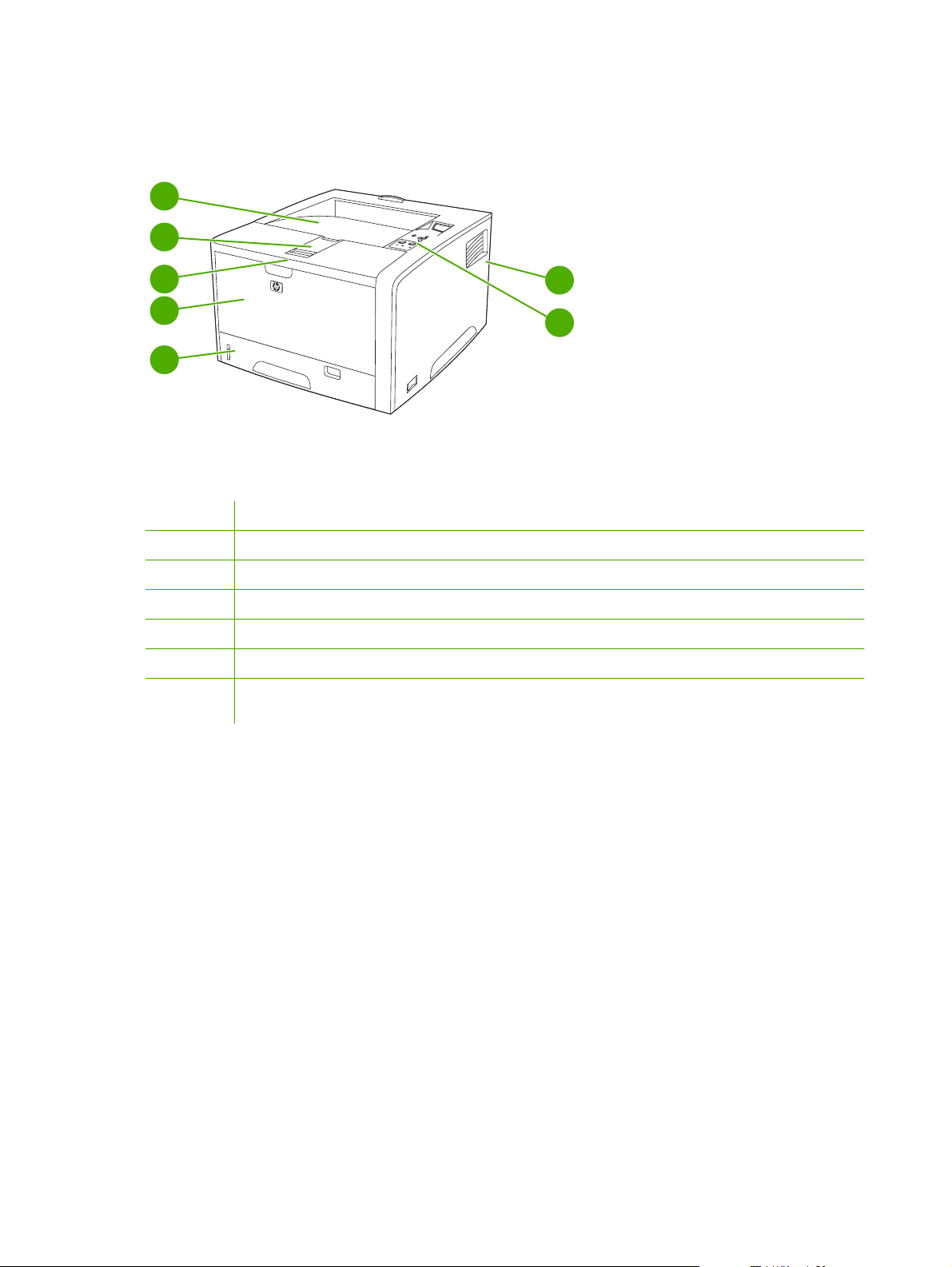
Walkaround
1
2
3
4
5
Figure 1-1 Front view
1
2
3
4
5
6
7
Face-down bin
Long-media extension
Latch to open the front cover (provides access to the print cartridge)
Tray 1 (pull to open)
Tray 2
Control panel
Right-side cover (provides access to DIMMs and CompactFlash cards) and EIO slot (CompactFlash and EIO
slot not available for the HP LaserJet 5200L)
7
6
6 Chapter 1 Product information ENWW
Page 27
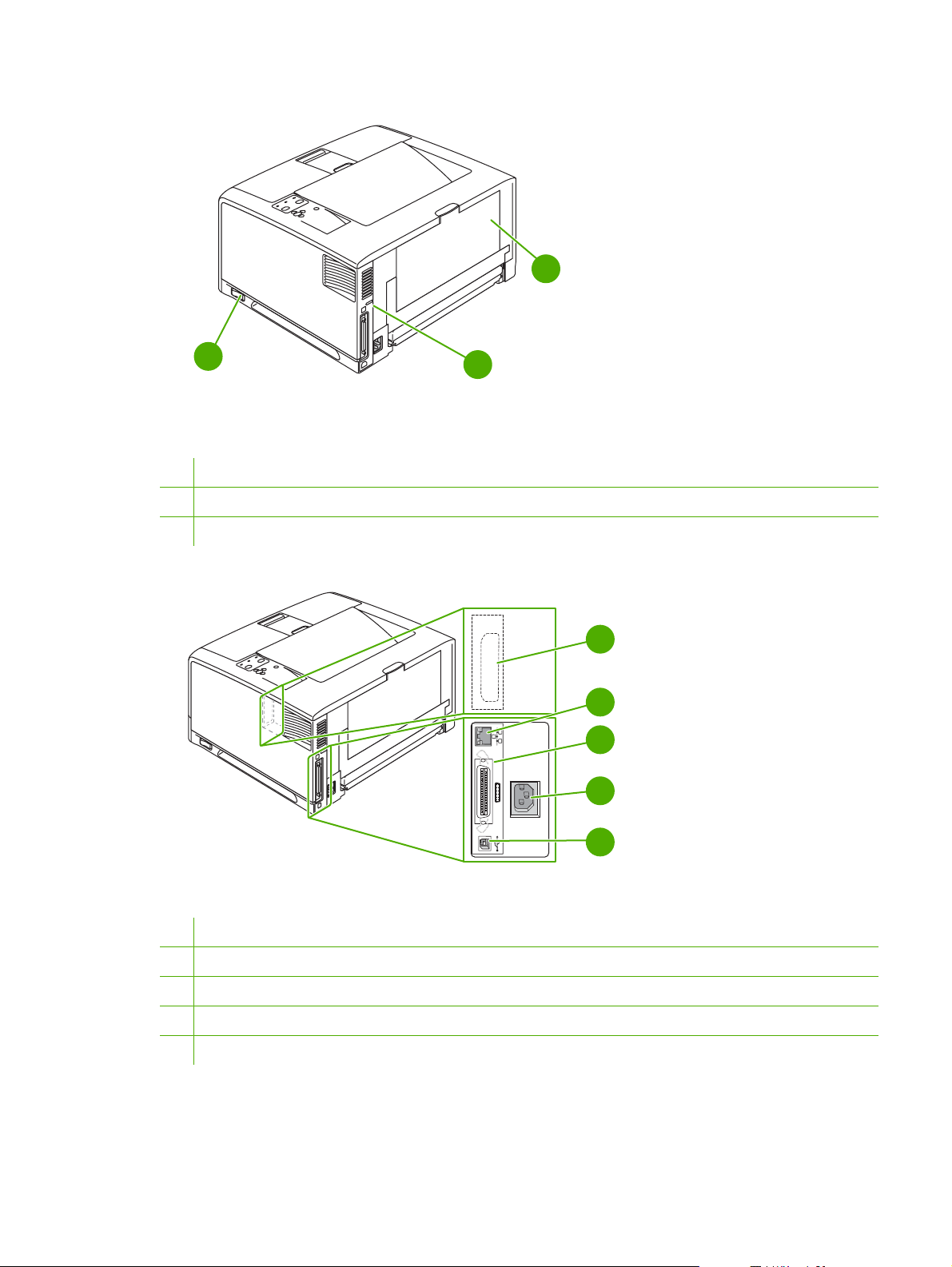
10
8
Figure 1-2 Back view
8 On/off switch
9 Interface ports
10 Face-up bin (pull to open)
9
1
EIO
2
3
4
5
Figure 1-3 Interface ports
1 EIO slot (not available for the HP LaserJet 5200L)
2 Network connection (HP LaserJet 5200n, 5200tn, and 5200dtn printers only)
3 IEEE 1284B-compliant parallel connection
4 Power-plug connection
5 Hi-Speed USB 2.0 connection
ENWW Walkaround 7
Page 28
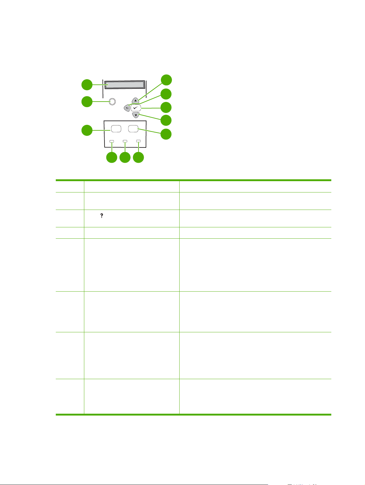
Control-panel overview
The control panel provides controls for printer functions and shows messages about the printer, print
jobs, and supplies status.
1
11
10
2
?
9
8
7
●
●
●
●
●
3
Menu
Menu Stop
Ready
4
Data
5
Stop
Attention
6
Figure 1-4 Control panel buttons and lights
Number Button or light Function
1 Control-panel display
2
3 Menu button
4 Ready light
Help ( ) button
Shows status information, menus, help information, and error
messages.
Provides information about the message on the control-panel
display.
Opens and closes menus.
On: The printer is online and ready to accept data to print.
Off: The printer cannot accept data because it is offline (paused)
or has experienced an error.
5 Data light
6 Attention light
7 Stop button
Blinking: The printer is going offline. The printer stops
●
processing the current print job and expels all of the active pages
from the paper path.
On: The printer has data to print, but is waiting to receive all of
●
the data.
Off: The printer has no data to print.
●
Blinking: The printer is processing or printing the data.
●
On: The printer has experienced a problem. Make note of the
●
message on the control-panel display, and then turn the printer
off and on.
Off: The printer is functioning without error.
●
Blinking: Action is required. See the control-panel display.
●
Cancels the current print job in process and expels all of the
●
active pages from the paper path. The time that it takes to cancel
the job depends on the size of the print job. (Press the button
only once.) Also clears continuable errors that are associated
with the canceled job.
8 Chapter 1 Product information ENWW
Page 29

NOTE The control-panel lights cycle while the print job is
cleared from both the printer and the computer, and then the
printer returns to the Ready state.
8
9
10
11
Down ( ) button
Select ( ) button
Back ( ) button
Up ( ) button
Navigates to the next item in the list, or decreases the values of
●
numeric items.
Clears an error condition when the condition is clearable
●
Saves the selected value for an item
●
Performs the action that is associated with the item that is
●
highlighted on the control-panel display
Backs up one level in the menu tree or backs up one numeric
●
entry
Closes menus if held down for more than 1 second
●
Navigates to the previous item in the list, or increases the value
●
of numeric items
ENWW Control-panel overview 9
Page 30

Printer software
The printing-system software is included with the printer. See the getting started guide for installation
instructions.
The printing system includes software for end users and network administrators, and printer drivers for
access to the printer features and communication with the computer.
NOTE For a list of printer drivers and updated HP printer software, go to www.hp.com/go/
lj5200_software or www.hp.com/go/lj5200L_software.
Printer drivers
Printer drivers allow you to gain access to the printer features and allow the computer to communicate
with the printer (using a printer language). Check the installation notes and readme files on the printer
CD for additional software and languages.
The HP LaserJet 5200 Series printers uses the PCL 5e, PCL 6, and PostScript 3 emulation printer
description language (PDL) drivers.
Use the PCL 6 printer driver for the best overall performance.
●
Use the PCL 5 printer driver for general office printing.
●
Use the PS driver for printing from PostScript-based programs, for compatibility with PostScript
●
Level 3 needs, or for PS flash font support.
Operating system PCL 5e PCL 6 PS 3 emulation
Windows 98, Windows Millennium (Me)
Windows 2000
Windows XP (32-bit)
Windows Server 2003 (32-bit)
Windows Server 2003 (64-bit)
Mac OS X V10.2 and later
1
Not all printer features are available from all drivers or operating systems.
2
For Windows 2000 and Windows XP (32-bit and 64-bit), download the PCL 5 driver from www.hp.com/go/lj5200_software
or www.hp.com/go/lj5200L_software.
3
For Windows XP (64-bit), download the PCL 6 driver from www.hp.com/go/lj5200_software or www.hp.com/go/
lj5200L_software.
The printer drivers include online Help that has instructions for common printing tasks and also describes
the buttons, checkboxes, and drop-down lists that are in the printer driver.
Driver Autoconfiguration
The HP LaserJet PCL 6 and PCL 5e drivers for Windows and the PS drivers for Windows 2000 and
Windows XP feature automatic discovery and driver configuration for printer accessories at the time of
installation. Some accessories that the Driver Autoconfiguration supports are the duplexing unit, optional
10 Chapter 1 Product information ENWW
Page 31

paper trays, and DIMMs. If the environment supports bidirectional communication, the installer presents
Driver Autoconfiguration as an installable component by default for a typical installation and for a custom
installation.
NOTE The duplexer and 500-sheet input tray (tray 3) are not available for the HP LaserJet
5200L.
Update Now
If you have modified the configuration of the HP LaserJet 5200 Series printer since installation, the driver
can be automatically updated with the new configuration in environments that support bidirectional
communication. Click the Update Now button to automatically reflect the new configuration in the driver.
NOTE The Update Now feature is not supported in environments where shared Windows 2000
or Windows XP clients are connected to Windows 2000 or Windows XP hosts.
HP Driver Preconfiguration
HP Driver Preconfiguration is a software architecture and set of tools that you can use to customize and
distribute HP software in managed corporate printing environments. Using HP Driver Preconfiguration,
information technology (IT) administrators can preconfigure the printing and device defaults for
HP printer drivers before installing the drivers in the network environment. For more information, see
the HP Driver Preconfiguration Support Guide, which is available at
www.hp.com/support/lj5200.
Additional drivers
The following drivers are not included on the CD, but are available from www.hp.com/go/
lj5200_software.
UNIX® model scripts
●
Linux drivers
●
ENWW Printer software 11
Page 32

Opening the printer drivers
Operating System To change the settings for all
print jobs until the software
program is closed
Windows 98 and Me 1. On the File menu in the
software program, click
Print.
2. Select the driver, and then
click Properties.
The steps can vary; this
procedure is most common.
Windows 2000, XP,
and Server 2003
Mac OS X V10.2 or
later
1. On the File menu in the
software program, click
Print.
2. Select the driver, and then
click Properties or
Preferences.
The steps can vary; this
procedure is most common.
1. On the File menu, click
Print.
2. Change the settings that
you want on the various
pop-up menus.
To change the default settings
for all print jobs
1. Click Start, click Settings,
and then click Printers.
2. Right-click the driver icon,
and then select
Properties.
1. Click Start, click Settings
(Windows 2000), and then
click Printers or Printers
and Faxes (Windows XP).
2. Right-click the driver icon,
and then select Printing
Preferences.
1. On the File menu, click
Print.
2. Change the settings that
you want on the various
pop-up menus.
3. On the Presets pop-up
menu, click Save as and
type a name for the preset.
To change the product
configuration settings
1. Click Start, click Settings,
and then click Printers.
2. Right-click the driver icon,
and then select
Properties.
3. Click the Configure tab.
1. Click Start, click Settings
(Windows 2000), and then
click Printers or Printers
and Faxes (Windows XP).
2. Right-click the driver icon,
and then select
Properties.
3. Click the Device Settings
tab.
1. In the Finder, on the Go
menu, click Applications.
2. Open Utilities, and then
open Print Center (Mac OS
X V10.2) or Printer Setup
Utility (Mac OS X V10.3 or
Mac OS X V10.4).
3. Click on the print queue.
These settings are saved in the
Presets menu. To use the new
settings, you must select the
saved preset option every time
you open a program and print.
4. On the Printers menu,
click Show Info.
5. Click the Installable
Options menu.
NOTE Configuration
settings might not be
available in Classic
mode.
Software for Macintosh computers
The HP installer provides PostScript Printer Description (PPD) files, Printer Dialog Extensions (PDEs),
and the HP Printer Utility for use with Macintosh computers.
For network connections, use the embedded Web server (EWS) to configure the printer. See
Web server on page 15.
Embedded
12 Chapter 1 Product information ENWW
Page 33

The printing system software includes the following components:
PostScript Printer Description (PPD) files
●
The PPDs, in combination with the Apple PostScript printer drivers, provide access to printer
features. Use the Apple PostScript printer driver that comes with the computer.
HP Printer Utility
●
Use the HP Printer Utility to set up printer features that are not available in the printer driver:
Name the printer.
●
Assign the printer to a zone on the network.
●
Assign an internet protocol (IP) address to the printer.
●
Download files and fonts.
●
Configure the printer for IP or AppleTalk printing.
●
You can use the HP Printer Utility when your printer uses a universal serial bus (USB) cable or is
connected to a TCP/IP-based network.
NOTE The HP Printer Utility is supported for Mac OS X V10.2 or later.
Installing Macintosh printing system software for networks
1. Connect the network cable between the HP Jetdirect print server and a network port.
2. Insert the CD into the CD-ROM drive. If the CD does not run automatically, double-click the CD
icon on the desktop.
3. Double-click the Installer icon in the HP LaserJet Installer folder.
4. Follow the instructions on the computer screen.
5. On the computer hard drive, open Applications, open Utilities, and then open Print Center or
Printer Setup Utility.
NOTE If you are using Mac OS X V10.3 or Mac OS X V10.4, then the Printer Setup
Utility has replaced the Print Center.
6. Click Add Printer.
7. Select Rendezvous as the connection type.
8. Select your printer from the list.
9. Click Add Printer.
10. Close the Print Center or the Printer Setup Utility.
Installing Macintosh printing system software for direct connections (USB)
NOTE Macintosh computers do not support parallel port connections.
ENWW Printer software 13
Page 34

The Apple PostScript driver must be installed in order to use the PPD files. Use the Apple PostScript
driver that came with your Macintosh computer.
1. Connect a USB cable between the USB port on the printer and the USB port on the computer. Use
a standard 2-meter (6.56-foot) USB cable.
2. Insert the printer CD into the CD-ROM drive and run the installer. If the CD menu does not run
automatically, double-click the CD icon on the desktop.
3. Double-click the Installer icon in the HP LaserJet Installer folder.
4. Follow the instructions on the computer screen.
USB queues are created automatically when the printer is attached to the computer. However, the
queue will use a generic PPD if the installer has not been run before the USB cable is connected.
Complete the following steps to change the queue PPD.
5. Open the Print Center or Printer Setup Utility.
6. Select the correct printer queue, and then click Show Info to open the Printer Info dialog box.
7. In the pop-up menu, select Printer Model, and then, in the pop-up menu in which Generic is
selected, select the correct PPD for the printer.
8. Print a test page from any software program to make sure that the software is correctly installed.
If installation fails, reinstall the software. If this fails, see the installation notes or late-breaking
readme files on the printer CD or the flyer that came in the printer box for help.
To remove software from Macintosh operating systems
To remove the software from a Macintosh computer, drag the PPD files to the trash can.
Software for networks
For a summary of available HP network installation and configuration software solutions, see the HP
Jetdirect Embedded Print Server Administrator’s Guide. You can find this guide on the printer CD.
HP Web Jetadmin
NOTE HP Web Jetadmin is not available for the HP LaserJet 5200L.
HP Web Jetadmin is a browser-based management tool for HP Jetdirect-connected printers within your
intranet, and it should be installed only on the network administrator’s computer.
To download a current version of HP Web Jetadmin and for the latest list of supported host systems,
www.hp.com/go/webjetadmin.
visit
When installed on a host server, any client can gain access to HP Web Jetadmin by using a supported
Web browser (such as Microsoft® Internet Explorer 4.x or Netscape Navigator 4.x or later) by navigating
to the HP Web Jetadmin host.
UNIX
For HP-UX and Solaris networks, go to www.hp.com/support/net_printing to download the HP Jetdirect
printer installer for UNIX.
14 Chapter 1 Product information ENWW
Page 35

Linux
For information, go to www.hp.com/go/linuxprinting.
Utilities
The printer is equipped with several utilities that make it easy to monitor and manage the printer on a
network.
HP Easy Printer Care Software
The HP Easy Printer Care Software is a program that you can use for the following tasks:
Checking the printer status
●
Checking the supplies status
●
Setting up alerts
●
Viewing printer documentation
●
Gaining access to troubleshooting and maintenance tools
●
You can view the HP Easy Printer Care Software when the printer is directly connected to your computer
or when it is connected to a network. Perform a complete software installation in order to use the HP Easy
Printer Care Software.
Embedded Web server
NOTE An embedded Web server is not available for the HP LaserJet 5200L.
The printer is equipped with an embedded Web server, which provides access to information about
printer and network activities. This information appears in a Web browser, such as Microsoft Internet
Explorer or Netscape Navigator.
The embedded Web server resides on the printer. It is not loaded on a network server.
The embedded Web server provides an interface to the printer that anyone who has a networkconnected computer and a standard Web browser can use. No special software is installed or
configured, but you must have a supported Web browser on your computer. To gain access to the
embedded Web server, type the IP address for the printer in the address line of the browser. (To find
the IP address, print a configuration page. For more information about printing a configuration page,
Configuration pages on page 283.
see
For a complete explanation of the features and functionality of the embedded Web server, see
Using
the embedded Web server on page 280.
Other components and utilities
Windows Macintosh OS
Software installer — automates the printing system
●
installation
PostScript Printer Description files (PPDs)—use with the
●
Apple PostScript drivers that come with the Mac OS
Online Web registration
●
The HP Printer Utility—change printer settings, view
●
status, and set up printer-event notification from a Mac.
This utility is supported for Mac OS X V10.2 and later.
ENWW Printer software 15
Page 36

Selecting print media
This printer accepts a variety of media, such as cut-sheet paper, including up to 100% recycled fiber
content paper; envelopes; labels; transparencies; and custom-size paper. Properties such as weight,
composition, grain, and moisture content are important factors that affect printer performance and output
quality. Paper that does not meet the guidelines that are outlined in this manual can cause the following
problems:
Poor print quality
●
Increased jams
●
Premature wear on the printer, requiring repair
●
NOTE Some paper might meet all of the guidelines in this manual and still not produce
satisfactory results. This might be the result of improper handling, unacceptable temperature and
humidity levels, or other variables over which Hewlett-Packard has no control. Before purchasing
large quantities of media, make sure that it meets the requirements that are specified in this user
guide and in the HP LaserJet Printer Family Print Media Guide, which is available for download
http://www.hp.com/support/ljpaperguide. Always test paper before buying large quantities.
at
CAUTION Using media that does not meet HP specifications can cause problems for the
printer, requiring repair. This repair is not covered by the HP warranty or service agreements.
Supported media sizes
NOTE The 500-sheet input tray (tray 3) and duplexer are not available for the HP LaserJet
5200L.
NOTE Auto duplexing is only supported for media weights of 60 to 120 g/m2 (16 to 32 lb).
Media size Dimensions Tray 1 Tray 2 and
Tray 3
Letter 216 x 279 mm (8.5 x 11 in)
60 to 199 g/m
Letter-R 279 x 216 mm (11 x 8.5 in)
A4 211 x 297 mm (8.3 x 11.7 in)
A4-R 297 x 211 mm (11.7 x 8.3 in)
Legal 216 x 356 mm (8.5 x 14 in)
Executive 185 x 267 mm (7.3 x 10.5 in)
Executive (JIS) 216 x 330 mm (8.5 x 13 in)
2
(16 to 53 lb)
Auto duplex Manual duplex
A5 147 x 211 mm (5.8 x 8.3 in)
B5 (JIS) 183 x 257 mm (7.2 x 10.1 in)
16 Chapter 1 Product information ENWW
Page 37

Media size Dimensions Tray 1 Tray 2 and
Tray 3
11 x 17 279 x 432 mm (11 x 17 in)
Auto duplex Manual duplex
A3 297 x 419 mm (11.7 x
B4 (JIS) 257 x 363 mm (10.1 x
8K 269 x 391 mm (10.6 x
8K 259 x 368 mm (10.2 x
8K 273 x 394 mm (10.75 x
16K 184 x 260 mm (7.24 x
16K 195 x 270 mm (7.68 x
16K 273 x 197 mm (10.75 x
Statement 140 x 216 mm (5.5 x 8.5 in)
12 x 18 305 x 457 mm (12 x 18 in)
A6 105 x 148 mm (4.14 x
16.5 in)
14.3 in)
15.4 in)
14.5 in)
15.5 in)
10.24 in)
10.63 in)
7.75 in)
5.83 in)
RA3 305 x 430 mm (12 x 16.93 in)
B6 128 x 182 mm (5.1 x 7.2 in)
S Postcard (JIS) 100 x 148 mm (3.94 x
5.83 in)
D Postcard (JIS) 148 x 200 mm (5.83 x
7.87 in)
Envelope #10 105 x 241 mm (4.13 x 9.5 in)
Envelope Monarch 98 x 191 mm (3.87 x 7.5 in)
Envelope C5 162 x 229 mm (6.38 x 9 in)
Envelope DL 110 x 220 mm (4.33 x
8.66 in)
Envelope B5 176 x 250 mm (6.93 x
9.84 in)
Custom
ENWW Selecting print media 17
Page 38

Supported media types
NOTE The 500-sheet input tray (tray 3) and duplexer are not available for the HP LaserJet
5200L.
Media type Weight Tray 1 Tray 2 and
Tray 3
Plain
Plain
Preprinted
Letterhead
Transparency 0.10 to 0.14 mm thick (4.7 to
Prepunched
Bond
Recycled
Envelopes
Colored paper
Labels 0.10 to 0.14 mm thick (4.7 to
60 to 199 g/m2 (16 to 53 lb)
60 to 120 g/m2 (16 to 32 lb)
60 to 120 g/m2 (16 to 32 lb)
60 to 120 g/m2 (16 to 32 lb)
5 mils thick)
60 to 120 g/m2 (16 to 32 lb)
60 to 120 g/m2 (16 to 32 lb)
60 to 120 g/m2 (16 to 32 lb)
75 to 90 g/m2 (20 to 24 lb)
60 to 120 g/m2 (16 to 32 lb)
5 mils thick)
Automatic
1
duplex
Manual duplex
Cardstock
Rough
Light
Vellum
Tough Paper 0.10 to 0.14 mm thick (4.7 to
Postcard
1
Automatic two-sided printing (duplexing) requires an HP LaserJet printer that is equipped with the optional duplexer.
135 to 176 g/m2 (36 to 47 lb)
60 to 75 g/m2 (16 to 20 lb)
60 to 120 g/m2 (16 to 32 lb)
5 mils thick)
135 to 176 g/m2 (36 to 47 lb)
18 Chapter 1 Product information ENWW
Page 39

2 Installation and configuration
What is in the box
●
Identification
●
Site requirements
●
Input/Output (I/O) configuration
●
Installing printer memory
●
Installing CompactFlash cards
●
Checking CompactFlash installation
●
Enabling memory (Windows only)
●
ENWW 19
Page 40

What is in the box
The following items come in the box with the printer.
Figure 2-1 What is in the shipping box
1. Printer
2. Print cartridge
3. Power cord
4. Getting started guide
5. Control-panel overlay
3 421
ter
rin
p
0
0
2
t5
e
rJ
ase
L
P
H
H
P
L
a
s
er
Je
t
5
20
0
p
ri
n
t
er
6 75
6. User guide and software on CD
20 Chapter 2 Installation and configuration ENWW
Page 41

Identification
The following section describes printer identification.
Model and serial numbers
The model number and serial numbers are listed on the identification labels located on the back of the
printer. The model number is alphanumeric, such as Q7543A for an HP LaserJet 5200 printer. The serial
number contains information about the country/region of origin, the printer version, production code,
and the production number of the printer. The following is a sample identification label.
country/region of origin printer version production number
HEWLETT-PACKARD
11311 CHINDEN BLVD.
BOISE, IDAHO 83714
USA
Assembled in U.S.A. printer engine made in Japan
Figure 2-2 Model and serial numbers
model number production code
50/60 Hz. 115V
Model No.: Q3668
CNBR212347
CNBR212347
Serial No.: JPBB605112
CNBR212347
CNBR212347
Model name Model number
HP LaserJet 5200 Q7543A
HP LaserJet 5200n Q7544A
HP LaserJet 5200tn Q7545A
HP LaserJet 5200dtn Q7546A
HP LaserJet 5200L Q7547A
ENWW Identification 21
Page 42

Site requirements
Select a sturdy, well-ventilated, dust-free area that is away from direct sunlight to position the printer.
Allow enough space around the printer to open the doors and trays.
Physical specifications
NOTE Printer weight does not include the print cartridge.
Table 2-1 Physical dimensions for the HP LaserJet 5200 Series printers
Printer model Height Depth Width Weight
HP LaserJet 5200, 5200n, and 5200L 275 mm (10.8 in) 563 mm (22.2 in) 490 mm (19.3 in) 20.2 kg (44.5 lb)
HP LaserJet 5200tn 405 mm (15.9 in) 600 mm (23.6 in) 490 mm (19.3 in)
HP LaserJet 5200dtn 405 mm (15.9 in) 600 mm (23.6 in) 490 mm (19.3 in)
500-sheet input tray (tray 3) 135 mm (5.3 in) 600 mm (23.6 in) 490 mm (19.3 in) 9 kg (20 lb)
Space requirements
5200tn: 30.2 kg
(66.5 lb)
5200dtn: 33.1 kg
(73 lb)
The printer must have the following amount of space above and around it for proper access and
ventilation.
1. 533 mm (21 in)
2. 1,060 mm (42 in)
3. 409 mm (15.9 in)
3
2
1
Figure 2-3 Space requirements
22 Chapter 2 Installation and configuration ENWW
Page 43

Input/Output (I/O) configuration
This section describes how to configure certain network parameters on the printer:
Parallel configuration
●
USB configuration
●
Network configuration
●
Connecting to a network or a computer
●
Parallel configuration
The printer supports network and parallel connections at the same time. A parallel connection is made
by connecting the printer to the computer using a bidirectional parallel cable (IEEE-1284 compliant) with
a connector plugged into the printer parallel port. The cable can be a maximum of 10 meters (30 feet)
long.
When used to describe a parallel interface, the term bidirectional indicates that the printer is able to both
receive data from the computer and send data to the computer through the parallel port. While the
parallel interface provides backwards compatibility, a USB or network connection is recommended to
optimize performance.
2
1
Figure 2-4 Parallel configuration
1 Parallel port
2 Parallel connector
USB configuration
The printer supports a Hi-Speed USB 2.0 port. The USB cable can be a maximum of 5 meters (16.4 feet)
long.
Connecting the USB cable
Plug the USB cable into the printer. Plug the other end of the USB cable into the computer.
ENWW Input/Output (I/O) configuration 23
Page 44

2
1
Figure 2-5 Connecting the USB cable
1 USB port
2 USB connector
Network configuration
NOTE Network configuration is not available for the HP LaserJet 5200L.
You might need to configure certain network parameters on the printer. You can configure these
parameters from the printer control panel, the embedded Web server, or for most networks, from the
HP Web Jetadmin software.
NOTE For more information about using the embedded Web server, see Using the embedded
Web server on page 280.
For a complete list of supported networks and for instructions on configuring network parameters from
software, see the HP Jetdirect Embedded Print Server Administrator’s Guide. The guide comes with
printers in which an HP Jetdirect embedded print server is installed.
Manually configuring TCP/IP parameters from the control panel
Use manual configuration to set an IP address, subnet mask, and default gateway.
Setting an IP address
1. Press Menu.
2. Press
3. Press
4. Press
5. Press
6. Press
7. Press
to highlight CONFIGURE DEVICE, and then press .
to highlight I/O, and then press .
to highlight EMBEDDED JETDIRECT, and then press .
to highlight TCP/IP, and then press .
to highlight MANUAL SETTINGS, and then press .
to highlight IP Address:, and then press .
8. Press the
24 Chapter 2 Installation and configuration ENWW
or arrow to increase or decrease the number for the first byte of the IP address.
Page 45

9. Press to move to the next set of numbers. (Press to move to the previous set of numbers.)
NOTE To cycle through the numbers more quickly, hold down the arrow button.
10. Repeat steps 8 and 9 until the correct IP address is complete, and then press to save the setting.
11. Press Menu to return to the Ready state.
Setting the subnet mask
1. Press Menu.
2. Press
3. Press
4. Press
5. Press
6. Press
7. Press
8. Press the
9. Press
10. Repeat steps 8 and 9 until the correct subnet mask is complete, and then press
subnet mask.
11. Press Menu to return to the Ready state.
Setting the default gateway
1. Press Menu.
2. Press
3. Press
to highlight CONFIGURE DEVICE, and then press .
to highlight I/O, and then press .
to highlight EMBEDDED JETDIRECT, and then press .
to highlight TCP/IP, and then press .
to highlight MANUAL SETTINGS, and then press .
to highlight SUBNET MASK, and then press .
or arrow to increase or decrease the number for the first byte of the subnet mask.
to move to the next set of numbers. (Press to move to the previous set of numbers.)
to highlight CONFIGURE DEVICE, and then press .
to highlight I/O, and then press .
to save the
4. Press
5. Press
6. Press
7. Press
8. Press the
gateway.
9. Press
10. Repeat steps 8 and 9 until the correct default gateway is complete, and then press
default gateway.
11. Press Menu to return to the Ready state.
ENWW Input/Output (I/O) configuration 25
to highlight EMBEDDED JETDIRECT, and then press .
to highlight TCP/IP, and then press .
to highlight MANUAL SETTINGS, and then press .
to highlight DEFAULT GATEWAY, and then press .
or arrow to increase or decrease the number for the first byte of the default
to move to the next set of numbers. (Press to move to the previous set of numbers.)
to save the
Page 46

Disabling network protocols (optional)
By factory default, all supported network protocols are enabled. Disabling unused protocols has the
following benefits:
Decreases printer-generated network traffic
●
Prevents unauthorized users from printing to the printer
●
Provides only pertinent information on the configuration page
●
Allows the printer control panel to display protocol-specific error and warning messages
●
To enable or disable IPX/SPX
NOTE Do not disable this protocol when using systems that print to the printer using IPX/SPX.
1. Press Menu.
2. Press
3. Press
4. Press
5. Press
6. Press
7. Press
8. Press Menu to return to the Ready state.
To enable or disable AppleTalk
NOTE Do not disable this protocol when using systems that print to the printer using AppleTalk.
1. Press Menu.
2. Press to highlight CONFIGURE DEVICE, and then press .
3. Press
4. Press
5. Press
to highlight CONFIGURE DEVICE, and then press .
to highlight I/O, and then press .
to highlight EMBEDDED JETDIRECT, and then press .
to highlight IPX/SPX, and then press .
or to select the desired option.
to set the selected option.
to highlight I/O, and then press .
to highlight EMBEDDED JETDIRECT, and then press .
to highlight APPLETALK, and then press .
6. Press
7. Press
8. Press Menu to return to the Ready state.
26 Chapter 2 Installation and configuration ENWW
or to select the desired option.
to set the selected option.
Page 47

To disable DLC/LLC
NOTE Do not disable this protocol when using systems that print to the printer using DLC/LLC.
1. Press Menu.
2. Press
3. Press
4. Press
5. Press
6. Press
7. Press
8. Press Menu to return to the Ready state.
to highlight CONFIGURE DEVICE, and then press .
to highlight I/O, and then press .
to highlight EMBEDDED JETDIRECT, and then press .
to highlight DLC/LLC, and then press .
or to select the desired option.
to set the selected option.
Enhanced I/O (EIO) configuration
NOTE EIO configuration is not available for the HP LaserJet 5200L.
NOTE If you are adding a print server to the base model, additional printer memory might be
required (minimum of 64 MB).
The enhanced input/output (EIO) slot holds compatible accessory devices, such as the HP Jetdirect
print server network cards or other devices. Plugging an EIO network card into the slot increases the
number of network interfaces available to the printer.
HP Jetdirect EIO print servers
HP Jetdirect print servers (network cards) can be installed in EIO slots. These cards support multiple
network protocols and operating systems. HP Jetdirect print servers facilitate network management by
allowing you to connect a printer directly to your network at any location. HP Jetdirect print servers also
support the Simple Network Management Protocol (SNMP), which provides network managers with
remote printer management and troubleshooting through the HP Web Jetadmin software.
NOTE Configure the card either through the control panel, the printer installation software, or
with HP Web Jetadmin software. See the HP Jetdirect print server documentation for more
information.
Connecting to a network or a computer
To connect to a network
1. Connect the network cable to the printer.
2. Find the IP address. On the control panel, press Menu. Select INFORMATION, and then select
PRINT CONFIGURATION. The IP address is on the embedded Jetdirect page, under “TCP/IP”.
NOTE You might need to assign an IP address depending on the type of network that is
installed.
ENWW Input/Output (I/O) configuration 27
Page 48

3. Configure an IP address (if necessary). On the control panel, press Menu. Select CONFIGURE
DEVICE, select I/O, and then select EMBEDDED JETDIRECT. Select TCP/IP, select CONFIG
METHOD, select MANUAL, and then select MANUAL SETTINGS. Use the control-panel buttons
to specify the IP address.
4. Prepare for software installation. Quit all of the programs (including terminate-and-stay resident
[TSR], antivirus, and firewall programs) on the print server or on each computer that will use the
printer.
5. Install the software. Insert the CD that came with the printer, and then click Install Printer on the
welcome screen. (If the welcome screen does not appear, run SETUP.EXE from the root directory
of the CD.)
6. Follow the onscreen instructions. When prompted, select Wired Networking. The installer shows
available printers. Select the appropriate IP address.
7. On the Installation Type screen select Full Installation to install the most common drivers and
software, select Basic Installation to install the minimum set of drivers and software
(recommended), or select Custom Installation.
NOTE See the HP Jetdirect Print Server Administrators Guide for more information. You can
find this guide on the printer CD.
To use Windows with a direct connection (USB)/parallel
1. Install the software from the CD before connecting the cable to the printer.
NOTE If the New Hardware Found message appears, insert the CD, follow the onscreen
instructions, and accept the default selections.
2. On the welcome screen, click Install Printer. The Setup Wizard appears.
NOTE If the welcome screen does not appear, click Start, and then click Run. Type
X:SETUP, replace X with the CD-ROM drive letter, and then click OK.
3. Follow the onscreen instructions. When prompted, connect a USB cable between the printer and
the computer.
NOTE HP does not recommend using USB hubs. Use a USB cable that is no longer than
5 meters (16.4 feet).
4. Click Finish. If prompted, restart the computer.
5. Test the software installation. Print a page from any program to make sure that the software is
correctly installed.
NOTE If the installation failed, reinstall the software.
28 Chapter 2 Installation and configuration ENWW
Page 49

To connect to a Macintosh computer
1. Connect a USB cable between the printer and the computer.
NOTE HP does not recommend using USB hubs. Use a USB cable that is no longer than
5 meters (16.4 feet).
2. Place the CD in the CD-ROM drive. For OS V9.1 to V9.2.x, go to step 3. For OS X, go to step 7.
3. Run the Installer and complete a custom install. Select all options, including USB Components
(Classic). When prompted, restart the computer.
4. Run the Apple Desktop Printer Utility from HD/Applications/Utilities. Double-click HP Printer
(USB), and then click OK. Next to the USB Printer Selection, click Change.
5. Select the printer, and then click OK. Next to Postscript Printer Description (PPD) File, click
Auto Setup, and then click Create. Save the printer setup.
6. On the desktop, highlight the printer. Click the Printing menu, and then click Set Default
Printer. Go to step 10.
7. Run the Installer and complete an easy install.
NOTE If OS X and OS V9.1 (Classic) to V9.2.x (Classic) are installed on the same
computer, the installer shows both the Classic and the OS X installation options.
8. From HD/Applications/Utilities/Print Center, start the Print Center. If the printer appears in the
Printer List, delete the printer. Click Add. On the next page, click the drop-down menu, and then
select USB.
9. From the Printer Model drop-down list, select HP. Under Model Name, select the printer, and then
click Add.
10. Test the software installation. Print a page from any program to make sure that the software is
correctly installed.
NOTE If the installation failed, reinstall the software.
ENWW Input/Output (I/O) configuration 29
Page 50

Installing printer memory
You might want to add more printer memory to the printer if you often print complex graphics, print
PostScript (PS) documents, or use many downloaded fonts. Added memory also gives you more
flexibility in supporting job-storage features, such as quick copying.
One DIMM slot and two CompactFlash slots (CompactFlash slots are not available for the HP LaserJet
5200L) are available for upgrading the printer with the following item:
More printer memory—DIMMs are available in 32, 64, 128, 256, and 512 MB.
●
CompactFlash font cards—Unlike standard printer memory, CompactFlash cards can be used to
●
permanently store downloaded items, such as fonts and forms, even when the printer is off. These
cards can also be used to enable the printer to print non-Roman characters.
Other DIMM- and CompactFlash-based printer languages and printer options.
●
For ordering information, see
NOTE Single inline memory modules (SIMMs) used in previous HP LaserJet printers are not
compatible with the printer.
The printer also has one EIO slot for expanding the printer networking capabilities. The EIO slot can be
used to upgrade the printer with an additional network connection, such as a wireless print server,
network card, or a connectivity card for a serial or AppleTalk connection (not available for the
HP LaserJet 5200L).
NOTE Some HP LaserJet 5200 Series printers come with a network device already installed.
The EIO slot may be used to provide networking capabilities in addition to those already built into
the printer (not available for the HP LaserJet 5200L).
To find out how much memory is installed in the printer, or to find out what is installed in the EIO slots,
print a configuration page. See
Accessories and supplies on page 312.
Configuration pages on page 283.
To install printer memory
CAUTION Static electricity can damage DIMMs. When handling DIMMs, either wear an
antistatic wrist strap or frequently touch the surface of the DIMM antistatic package, then touch
bare metal on the printer.
The HP LaserJet 5200 Series printers come with one DIMM slot. If desired, you can replace a DIMM
installed in the slot with a higher memory DIMM for all HP LaserJet 5200 Series printers.
30 Chapter 2 Installation and configuration ENWW
Page 51

If you have not already done so, print a configuration page to find out how much memory is installed in
the printer before adding more memory. See
Configuration pages on page 283.
1. After the configuration page has printed, turn the printer off and disconnect the power cord.
2. Disconnect all interface cables.
3. Remove the right side panel by sliding it toward the rear of the printer until the side slides from the
printer.
ENWW Installing printer memory 31
Page 52

4. Open the access door by pulling on the metal tab.
5. Remove the DIMM from the antistatic package.
CAUTION To reduce the possibility of damage caused by static electricity, always wear
an electrostatic discharge (ESD) wrist strap or touch the surface of the antistatic package
before handling DIMMs.
6. Hold the DIMM by the edges, and align the notches on the DIMM with the DIMM slot. (Check that
the locks on each side of the DIMM slot are open.)
32 Chapter 2 Installation and configuration ENWW
Page 53

7. Press the DIMM straight into the slot, and press firmly. Make sure the locks on each side of the
DIMM snap into place.
NOTE To remove a DIMM, first release the locks.
8. Close the access door, and press firmly until it snaps into place.
9. To replace the right side panel, line up the alignment arrows and slide the panel toward the front
of the printer until it latches into place.
ENWW Installing printer memory 33
Page 54

10. Reconnect the interface cable(s) and the power cord.
11. Turn the printer on.
Checking DIMM installation
After installing the DIMM, make sure that the installation was successful.
To verify that DIMMs are installed correctly
1. Turn the printer on. Check that the Ready light is illuminated after the printer has gone through the
startup sequence. If an error message appears, a DIMM might have been incorrectly installed.
2. Print a configuration page (see
3. Check the memory section on the configuration page and compare it to the configuration page that
was printed before the memory installation. If the amount of memory has not increased, the DIMM
might not be installed correctly, or the DIMM might be defective. Repeat the installation procedure.
If necessary, install a different DIMM.
NOTE If you installed a printer language (personality), check the "Installed Personalities and
Options" section on the configuration page. This area should list the new printer language.
Configuration pages on page 283).
34 Chapter 2 Installation and configuration ENWW
Page 55

Installing CompactFlash cards
NOTE CompactFlash cards are not available for the HP LaserJet 5200L.
Up to two CompactFlash cards can be installed to add fonts to the printer.
To install a CompactFlash card
1. After the configuration page has printed, turn the printer off and disconnect the power cord.
2. Disconnect all interface cables.
3. Remove the right side panel by sliding it towards the rear of the printer until the side slides from
the printer.
ENWW Installing CompactFlash cards 35
Page 56

4. Open the access door by pulling on the metal tab.
5. Remove the new CompactFlash card from its package.
6. Hold the CompactFlash card by its edges and line up the grooves in the side of the card with the
tabs in the CompactFlash card slot.
36 Chapter 2 Installation and configuration ENWW
Page 57

7. Slide the CompactFlash card into place.
8. Close the access door, and press firmly until it snaps into place.
9. To replace the right side panel, line up the alignment arrows and slide the panel toward the front
of the printer until it latches into place.
ENWW Installing CompactFlash cards 37
Page 58

10. Reconnect the interface cable(s) and the power cord.
Use Device Storage Manager in HP Web Jetadmin to manage fonts. For more information, see the Help
in HP Web Jetadmin.
38 Chapter 2 Installation and configuration ENWW
Page 59

Checking CompactFlash installation
After installing the CompactFlash card, make sure that the installation was successful.
To verify that CompactFlash cards are installed correctly
1. Turn the printer on. Check that the Ready light is illuminated after the printer has gone through the
startup sequence. If an error message appears, a CompactFlash card might have been incorrectly
installed.
2. Print a configuration page (see
3. Check the installed personalities and options section on the configuration page and compare it to
the configuration page that was printed before to verify CompactFlash installation. If there is not
any information on the installed CompactFlash card, repeat the installation procedure. If necessary,
install a different CompactFlash card.
NOTE If you installed a printer language (personality), check the "Installed Personalities and
Options" section on the configuration page. This area should list the new printer language.
Configuration pages on page 283).
ENWW Checking CompactFlash installation 39
Page 60

Enabling memory (Windows only)
1. On the Start menu, point to Settings, and click Printers or Printers and Faxes.
2. Select this printer and select Properties.
3. On the Configure tab, click More.
4. In the Total Memory field, type or select the total amount of memory that is now installed.
5. Click OK.
40 Chapter 2 Installation and configuration ENWW
Page 61

3 Maintenance
Managing supplies
●
Replacing supplies and parts
●
Cleaning the printer
●
ENWW 41
Page 62

Managing supplies
Using, storing, and monitoring the print cartridge can help ensure high-quality printer output.
Approximate print-cartridge replacement intervals
Print cartridge Page count Approximate time period
Black 12,000 pages 6 months
1
Approximate life is based on 2,000 pages per month.
2
Approximate average A4-/letter-size page count based on approximately 5% coverage.
To order supplies online, go to www.hp.com/support/lj5200 or www.hp.com/support/lj5200L.
Managing the print cartridge
Print-cartridge life expectancy
The average cartridge yield is 12,000 pages in accordance with ISO/IEC 19752. Actual cartridge yield
depends on specific use.
CAUTION Hewlett-Packard does not recommend full-time use of EconoMode. (If EconoMode
is used consistently to print media with less than 5% toner coverage, the toner supply might
outlast the mechanical parts in the print cartridge.)
Print-cartridge storage
Do not remove the print cartridge from its package until you are ready to use it.
CAUTION To prevent damage to the print cartridge, do not expose it to light for more than a
few minutes.
HP print cartridges
When you use a genuine new HP print cartridge, you can obtain the following supplies information:
Percentage of supplies remaining
●
Estimated number of pages remaining
●
Number of pages printed
●
HP policy on non-HP print cartridges
Hewlett-Packard Company cannot recommend the use of non-HP print cartridges, either new or
remanufactured. Because they are not HP products, HP cannot influence their design or control their
quality.
CAUTION Any damage caused by a non-HP print cartridge is not covered under the
HP warranty and service agreements.
To install a new HP print cartridge, see Changing the print cartridge on page 44. To recycle the used
cartridge, follow the instructions included with the new cartridge.
42 Chapter 3 Maintenance ENWW
Page 63

Print-cartridge authentication
The printer automatically authenticates the print cartridge when it is inserted into the printer. During
authentication, the printer will let you know whether a cartridge is a genuine HP print cartridge.
If the printer control-panel message states that this is not a genuine HP print cartridge and you believe
you purchased an HP print cartridge, see
HP fraud hotline and Web site on page 43.
HP fraud hotline and Web site
Call the HP fraud hotline (1-877-219-3183, toll-free in North America) or go to www.hp.com/go/
anticounterfeit when you install an HP print cartridge and the printer message says the cartridge is non-
HP. HP will help determine if the product is genuine and take steps to resolve the problem.
Your print cartridge might not be a genuine HP print cartridge if you notice the following:
You are experiencing a high number of problems with the print cartridge.
●
The cartridge does not look like it usually does (for example, the orange pull tab is missing, or the
●
packaging differs from HP packaging).
Checking supply levels
You can check the toner-supply level by using the control panel, HP Web Jetadmin (not available for
the HP LaserJet 5200L), or the embedded Web server (not available for the HP LaserJet 5200L).
To check supplies by using the control panel
1. Press Menu.
2. Press
3. Press
to highlight INFORMATION, and then press .
to highlight PRINT SUPPLIES STATUS, and then press .
To check supplies by using HP Web Jetadmin
1. In HP Web Jetadmin, select PRINTER, and then press .
2. The supplies status page displays the print-cartridge information.
To check supplies using the embedded Web server
1. In a Web browser, type the IP address for the printer home page.
2. On the left side of the computer screen, click Supplies Status. The supplies status page displays
the print-cartridge information.
ENWW Managing supplies 43
Page 64

Replacing supplies and parts
Carefully follow the guidelines in this section when replacing printer supplies.
Supply replacement guidelines
To facilitate the replacement of supplies, keep the following guidelines in mind when setting up the
printer.
Sufficient space is required above and in the front of the printer for removing supplies.
●
The printer should be located on a flat, sturdy surface.
●
For instructions on installing supplies, see the installation guides provided with each supply item or see
more information at
CAUTION Hewlett-Packard recommends the use of HP products in this printer. Use of non-
HP products may cause problems requiring service that is not covered by the HP warranty or
service agreements.
Life expectancy of consumable parts
Deteriorated or damaged consumable parts might need to be replaced at least once before the warranty
expires. Only replace parts that are faulty.
www.hp.com/support/lj5200 or www.hp.com/support/lj5200L.
Part Part number Quantity Life expectancy (pages)
1 Cassette pickup roller RM1-0731-030 1 200,000
2 Cassette paper separation pad RM1-2546-000 1 200,000
3 Tray 1 pickup roller RL1-0915-000 1 200,000
4 Tray 1 separation pad RM1-2462-000 1 200,000
5 Transfer roller RM1-2485-000 200,000
6 Paper-feed pickup roller (tray 2) RM1-0036-000 1 200,000
7 Paper-feed separation roller
(tray 2)
8 Paper-feed feed roller (tray 3) RM1-0037-000 1 200,000
RM1-0037-000 1 200,000
Changing the print cartridge
When a print cartridge approaches the end of useful life, a message appears on the control panel
recommending that you order a replacement. The printer can continue to print using the current print
cartridge until a message appears instructing you to replace the cartridge.
NOTE If toner gets on clothing, wipe it off with a dry cloth and wash the clothes in cold water.
Hot water sets toner into fabric.
44 Chapter 3 Maintenance ENWW
Page 65

To change the print cartridge
1. Open the front cover.
2. Remove the used print cartridge from the printer.
3. Remove the new print cartridge from the bag. Place the used print cartridge in the bag for recycling.
ENWW Replacing supplies and parts 45
Page 66

4. Grasp both sides of the print cartridge and distribute the toner by gently rocking the print cartridge.
CAUTION Hold the print cartridge by the end caps.
5. Remove the shipping tape from the new print cartridge. Discard the shipping tape according to
local regulations.
6. Align the print cartridge with the tracks inside the printer, and, using the handle, insert the print
cartridge until it is firmly seated, and then close the front door.
After a short time, the control panel should display Ready.
7. Installation is complete. Place the used print cartridge in the box in which the new cartridge arrived.
See the enclosed recycling guide for recycling instructions.
8. If you are using a non-HP print cartridge, check the printer control panel for further instructions.
46 Chapter 3 Maintenance ENWW
Page 67

For additional help, go to www.hp.com/support/lj5200 or www.hp.com/support/lj5200L. For information
about recycling used print cartridges, go to
www.hp.com/go/recycle.
ENWW Replacing supplies and parts 47
Page 68

Cleaning the printer
During the printing process, paper, toner, and dust particles can accumulate inside the printer. Over
time, this buildup can cause print-quality problems, such as toner specks or smearing (see
Troubleshooting print-quality problems on page 238). This printer has a cleaning mode that can correct
and prevent these types of problems.
Figure 3-1 Cleaning the printer
1. Fuser unit inlet guide: Wipe with a lint-free cloth.
2. Transfer charging roller: Do not touch or clean the transfer charging roller it is absolutely
necessary. If you must clean the transfer charging roller, clean it with a dry-lint free cloth. Do not
touch the roller and do not use water or solvent to clean it.
3. Registration roller: Wipe with a lint-free cloth.
4. Tray 1 pickup roller: Wipe with a lint-free cloth.
5. Tray 1 separation pad: Wipe the rubber part with a lint-free cloth.
6. Tray 2 separation pad: Wipe the rubber part with a lint-free cloth.
7. Paper-feeder separation roller: Wipe with a lint-free cloth.
8. Paper-feeder feed roller: Wipe with a lint-free cloth.
48 Chapter 3 Maintenance ENWW
Page 69

9. Paper-feeder pickup roller: Wipe with a lint-free cloth.
10. Tray 2 pickup roller: Wipe with a lint-free cloth.
11. Duplexer feed rollers: Wipe with a lint-free cloth.
Cleaning the printer manually
Clean the outer surfaces with an HP Toner Cleaning Cloth or a water-dampened cloth.
WARNING! Before you begin these steps, turn the printer off and unplug all power cords to
avoid shock hazard. Be careful when cleaning around the fuser area. It might be hot.
CAUTION To avoid permanent damage to the print cartridge, do not use ammonia-based
cleaners on or around the printer. If toner gets on your clothes, wipe it off with a dry cloth and
wash your clothes in cold water. Hot water sets toner into fabric.
Component Cleaning Method
Outer covers Use an HP Toner Cleaning Cloth (part number 5090-3379) or
a water-dampened cloth. Do not use solvents or ammoniabased cleaners.
Inside, general With a dry, lint-free cloth, wipe any dust, spilled toner, and
paper particles from the paper path area, the registration roller,
and the print-cartridge cavity.
Paper-pickup rollers Clean with lint-free paper. If dirt cannot be removed, dampen
the paper with alcohol.
Cleaning the paper path using the printer control panel
1. Press Menu.
2. Press
3. Press to highlight PRINT QUALITY, and then press .
4. Press to highlight CREATE CLEANING PAGE, and then press .
5. Remove all paper from tray 1.
6. Remove the cleaning page and load it face-down in tray 1.
7. At the printer control panel, press to highlight PROCESS CLEANING PAGE, and then
press
to highlight CONFIGURE DEVICE, and then press .
NOTE If your printer has an automatic duplexer, go to step 7.
NOTE If you are not in the menus, navigate to PRINT QUALITY by using the previous
instructions.
.
ENWW Cleaning the printer 49
Page 70

Cleaning spilled toner
Defective print cartridges can develop leaks. Also, after a jam has occurred, some toner might remain
on the rollers and guides inside the printer. The pages that print immediately after the jam can pick up
this toner. Use a vacuum that is designed for picking up fine particle.
Vacuum specifications
Do not use a conventional vacuum designed for LaserJet printers or copiers to vacuum the printer or
any spilled toner. The toner particles used in this product might be too fine for effective vacuuming and
could result in damage to conventional vacuums.
You can use a vacuum specifically designed for cleaning if it can filter fine particles (5 microns in
diameter).
NOTE Dispose of waste toner in accordance with local requirements. Do not discharge toner
particles into drains.
50 Chapter 3 Maintenance ENWW
Page 71

4 Theory of operation
This chapter presents an overview of the major components of the HP LaserJet 5200 Series printers,
and includes a detailed discussion of the image-formation system.
ENWW 51
Page 72

Engine control system
The engine control system coordinates all printer functions and drives the other three systems.
The engine control system contains these components:
DC controller PCA
●
High-voltage power supply PCA
●
Low-voltage power supply unit
●
Figure 4-1 Engine control system
Table 4-1 Sequence of operation
Period Duration Purpose Remarks
WAIT period From the time the power is
turned on until the initial drive
for the main motor is
complete
STBY (Standby period) From end of the WAIT or
LSTR period until either the
print command is received
from the formatter or the
power is turned off
INTR (Initial rotation) From the time the print
command is received until the
pickup solenoid is turned on
PRINT From the end of INTR period
until the fuser paper sensor
detects the trailing edge of
paper
LSTR (Last rotation) From the end of the PRINT
period until the fuser motor
stops rotating
Removes the charge that
creates a potential difference
from the drum surface, and
adjusts the drum phase
Maintains the printer in
readiness for a print
command and maintains the
heater at a targeted
temperature
Prepares the photosensitive
drum for printing and cleans
the transfer charging roller
Forms the images on the
photosensitive drum and
transfers the toner image to
the print media
Moves the last printed sheet
out of the printer
Detects cartridge presence
The printer enters the INTR
period as soon as the
formatter sends another print
command
52 Chapter 4 Theory of operation ENWW
Page 73

Power-on sequence
Power on
Initialize CPU
Video interface communication start
Residual paper check
Detecting paper presence by each sensor signaling
Initial drive for main motor
Initial drive for fuser heater
Controlling fuser temperature targeting for 120˚C
Initial drive for fuser motor
High-voltage control
Detecting cartridge presence after primary ac bias is
applied and cleaning transfer roller
Failure/Abnormality check
Detecting fuser-unit failure and door-open error
Communication with memory tag
Figure 4-2 Power-on sequence
Motors, fans, and solenoids
4
2
1
3
Figure 4-3 Motors, fans, and solenoids (1 of 2)
ENWW Engine control system 53
Page 74

Figure 4-4 Motors, fans, and solenoids (2 of 2)
1. Main fan (FM1)
2. Sub fan
3. Main motor
5
6
7
4. Fuser motor
5. Lifter motor
6. Paper-feeder pickup motor
7. Paper-feeder pickup solenoid
54 Chapter 4 Theory of operation ENWW
Page 75

Laser/scanner system
The formatter sends video signals to the DC controller, which controls the laser/scanner. When the laser/
scanner system receives those signals it converts them to latent images on the photosensitive drum.
Figure 4-5 Laser/scanner system
ENWW Laser/scanner system 55
Page 76

Pickup-and-feed-system
The pickup-and-feed system consists of two pickup sources (tray 2, which is the cassette, and tray 1,
the multipurpose tray) and two delivery destinations (face-down top bin and face-up rear bin).
The multipurpose paper sensor (SR3) detects paper in the multipurpose tray, and the cassette paper
sensor (SR2) detects media in tray 2.
The DC controller controls the main motor, fuser motor, cassette pick-up solenoid, and multipurpose
pickup solenoid.
The four sensors (top-of-page sensor, paper-loop sensor, fuser-delivery sensor, and bin paper-full
sensor) on the paper-transport path detect the arrival and passage of media. If the media does not reach
or pass each sensor within a specified period of time, the DC controller determines that a jam has
occurred and alerts the formatter.
56 Chapter 4 Theory of operation ENWW
Page 77

Figure 4-6 Pickup-and-feed-system
Cassette (tray 2) pickup mechanism
When tray 2 is correctly installed, SW detects its presence. The cassette paper sensor (SR2) detects
whether media is in the cassette, and the cassette media sensor detects the type of media. When tray 2
is correctly installed and contains the correct media type, the pickup operation begins.
1. The DC controller receives a print command from the formatter, and then begins rotating the pickup-
and-feed motor (M1) at the correct speed for the media type.
2. After the motor reaches the correct speed and the fuser reaches the correct temperature, the
cassette pickup solenoid (SL1) turns on and the cassette pickup roller begins rotating.
ENWW Pickup-and-feed-system 57
Page 78

3. The cassette lifting plate lifts the media stack, and the cassette pickup roller picks up one sheet.
The separation pad prevents multi-feeds.
1 )
Paper
2 )
3 )
Cassette pick-up roller
Lifting plate
Figure 4-7 Cassette (tray 2) pickup mechanism
Spring
Paper
separation pad
Multipurpose-tray (tray 1) pickup mechanism
Tray 2 must be installed in order for tray 1, the multipurpose (MP) tray, to operate. The MP-tray paper
sensor (SR3) detects whether media is present. When tray 1 is correctly installed and contains media,
the MP-tray pickup operation begins.
1. The DC controller receives a print command from the formatter and rotates the main motor (M1)
at the correct speed for the media type.
2. After the motor reaches the correct speed and the fuser is at the correct temperature, the MP pickup
solenoid (SL2) turns on and the MP pickup roller rotates.
3. The MP pickup roller picks up one sheet of media. The separation pad prevents multi-feeds.
4. The MP tray media sensor detects the media type as the media enters the printer.
Jam detection
1. Cartridge sensor assembly
2. Paper and registration sensor covers
3. Cassette media sensor
A pick-up delay jam can occur during operation. The printer makes three attempts to pick up media from
a tray. When the top-of-page sensor (SR5) does not detect the leading edge of a page within 4.5 seconds
after the third attempt, the printing operation stops.
58 Chapter 4 Theory of operation ENWW
Page 79

Image-formation system
The image-formation system, which forms a toner image on media, consists of several interdependent
systems:
Electrostatic latent-image-formation
●
Developing
●
Transfer
●
Fuser
●
Drum cleaning
●
The printer includes one print cartridge that contains the toner that is used to create the image on the
media.
Laser/Scanner unit
Fixing film unit
Fixing
pressure
roller
Fixing unit
VDO1,/VDO1,VDO2,/VDO2
Print command
Formatter
VIDEO signal
Laser beam
Photosensitive
drum
Transfer charging roller
DC controller
PCB
Cartridge
High-voltage
power supply
PCB
FSRB
TR
PRl, DEV
Figure 4-8 Image-formation system
ENWW Image-formation system 59
Page 80

Image-formation process
Laser printing requires the interaction of several different technologies, including electronics, optics, and
electrographics, to produce a printed page. Each process functions independently and must be
coordinated with the other processes. Image formation consists of the following four processes:
1. Latent-image formation
2. Developing
3. Image transfer
4. Fusing
Electrostatic latent-image-formation block
Paper path
2. Laser beam exposure
Direction of the drum rotation
1. Primary charging
Drum cleaning block
Delivery
Fusing block
6. Fusing
3. Development
7. Drum cleaning
5. Separation 4. Transfer
Develoment block
Pick-up
Transfer block
Figure 4-9 Image-formation process
Latent-image formation block
During the two steps that comprise this block, a negative charge is applied to the photosensitive drum
to form a latent image, which is invisible.
Step 1: primary charging
A high-voltage DC bias is applied to the primary charging roller, which is made of conductive rubber and
is in contact with the drum surface. As the roller moves across the drum, it applies the negative charge.
0
Time (t)
Exposed area
Unexposed area
Primary
Surface potential (V)
charging
(step 1)
Laser
beam
exposure
(step 2)
Transfer
(step 4)
Primary
charging
(step 1)
Figure 4-10 Primary charging
60 Chapter 4 Theory of operation ENWW
Page 81

Step 2: laser-beam exposure
The laser beam scans the photosensitive drum to neutralize the negative charge on portions of the drum
surface. An electrostatic latent image forms where the negative charge was neutralized.
Laser beam
Unexposed area Exposed area
Figure 4-11 Laser-beam exposure
Development block
The developing cylinder comes in contact with the photosensitive drum and deposits toner on the
electrostatic latent image.
Step 3: developing
Toner acquires a negative charge from the friction that occurs when the developing cylinder rotates
against the developing blade. When the negatively charged toner comes in contact with the drum, it
adheres to the electrostatic latent image, which becomes visible.
Transfer block
Step 4: image transfer
The positively charged media is transferred over the photosensitive drum. As the media passes between
the transfer roller and the drum, the transfer roller applies a positively DC bias to the media. The
positively charged media attracts the negatively charged toner from the drum surface.
Photo-
sensitive
drum
Transfer charging roller
Paper
Figure 4-12 Image transfer
ENWW Image-formation system 61
Page 82

Step 5: separation from the drum
The elasticity of the print media causes it to separate from the drum surface. The sheet continues
travelling through the printer. The static charge eliminator reduces static discharge.
Photo-
sensitive
drum
Static charge eliminator
Transfer charging roller
Figure 4-13 Separation from the drum
Paper
Fixing block
Until the fusing stage is complete, the image is not permanently affixed to the print media. The toner
can be easily smudged until the heat and pressure of the fusing process fix the image to the sheet.
Step 6: fusing
The printer uses a ceramic heater to accomplish the on-demand fusing process. The heater has a low
heat capacity, which results in a short warm-up period and yields energy savings.
Figure 4-14 Fusing
Drum-cleaning block
Not all of the toner is removed from the photosensitive drum during the transfer stage. During the
cleaning stage, the residual (waste) toner and residual electrical charge is cleared from the drum surface
to prepare the surface for the next latent-image formation.
Step 7: drum cleaning
The cleaning blade scrapes the residual toner off the surface of the photosensitive drum and deposits
it in the waste-toner container. The drum is now clear, and is ready for the next image-formation process.
62 Chapter 4 Theory of operation ENWW
Page 83

Print cartridge
This printer has one print cartridge that holds magnetic, single-component toner. In addition to the toner,
the cartridge contains a developing cylinder, toner-feed roller, and stirrer. The developer motor rotates
these parts so that the print cartridge can deposit toner to form a visible image on the photosensitive
drum.
The print cartridge in this printer includes the photosensitive drum, the primary charging roller, and the
developing roller. The cartridge performs these functions:
Memory-tag control
●
Developing-roller engagement and disengagement control
●
DC controller PCB
Main motor
MAIN MOTOR DRIVE signal
M
Memory data
TONER LEVEL signal
Memory tag contact
Photosensitive drum
Memory tag
Figure 4-15 Print cartridge
Print-cartridge activation
A memory tag is a nonvolatile memory that is built into the print cartridge. The DC controller reads and
writes data that is stored in the memory tag. The DC controller reads data at the following times:
When the power is turned on
●
When someone closes the front cover
●
When it receives a command from the formatter
●
ENWW Image-formation system 63
Page 84

The DC controller writes information at the following times:
At a specified interval during printing
●
When it receives a command from the formatter
●
When the read/write operation fails or the wrong data is read or written, the DC controller determines
that an error has occurred and notifies the formatter of a cartridge-memory abnormality. Printing then
stops.
64 Chapter 4 Theory of operation ENWW
Page 85

5 Removal and replacement
Removal and replacement strategy
●
Customer self-repair parts
●
External doors, covers, and panels
●
Internal assemblies
●
Printed circuit assemblies (PCAs)
●
Duplexer
●
500-sheet feeder
●
ENWW 65
Page 86

Removal and replacement strategy
Introduction
This chapter describes the removal and replacement of field-replaceable units (FRUs) only.
Replacing FRUs is generally the reverse of removal. Notes are included to provide directions for difficult
or critical replacement procedures.
HP does not support repairing individual subassemblies or troubleshooting to the component level.
Never operate or service the printer with the protective cover removed from the laser/scanner assembly.
The reflected beam, although invisible, can damage your eyes.
The sheet-metal parts can have sharp edges. Be careful when handling sheet-metal parts.
CAUTION Some parts are sensitive to electrostatic discharge (ESD). Look for the ESD
reminder when removing printer parts. Always perform service work at an ESD-protected
workstation or mat. If an ESD workstation or mat is not available, ground yourself by touching
the sheet-metal chassis before touching an ESD-sensitive part.
Protect the ESD-sensitive parts by placing them in ESD pouches when they are out of the printer.
CAUTION Do not bend or fold the flat flexible cables (FFCs) during removal or installation.
NOTE To install a self-tapping screw, first turn it counterclockwise to align it with the existing
thread pattern, and then carefully turn it clockwise to tighten. Do not overtighten. If a self-tapping
screw-hole becomes stripped, repair the screw-hole or replace the affected assembly.
Required tools
#2 Phillips screwdriver with a magnetic tip and a 152-mm (6-inch) shaft length
●
Small flatblade screwdriver
●
Needle-nose pliers
●
ESD strap (if one is available)
●
Penlight
●
CAUTION Always use a Phillips screwdriver (callout 1). Do not use a pozidrive screwdriver
(callout 2) or any motorized screwdriver. These can damage screws or screw threads.
Figure 5-1 Screwdrivers
66 Chapter 5 Removal and replacement ENWW
Page 87

CAUTION Do not pull directly on the wires to disconnect them. Always pull on the plastic body
of a connector to avoid damaging the connector wires.
Types of screws
Illustration Description Size Part number Use
Screw with washer M3X8 XA9–1420–000CN Used to secure metal
components to metal
components (for
example, a ground wire
to the frame)
Screw, RS M3X6
M3X10
Screw, tapping M3X6 XA9–1503–000CN
Screw M3X8 XA9–1686–000CN
Screw P-M3X8 XB4–5300–807CN
Screw, tapping, truss
head
M4X10 XB4–7401–005CN Used to secure
XA9–1499–000CN Used to secure metal to
metal
anything to plastic
Service approach
Printer repair normally begins by using the printer internal diagnostics and the following two-step
process:
1. Isolate the problem to the major system (for example, the network or server, or the printer).
2. Troubleshoot the problem by using the procedures in chapter 6.
After you locate a faulty part, the printer can usually be repaired at the assembly level by replacing FRUs.
Some mechanical assemblies might need to be repaired at the subassembly level. Hewlett-Packard
Company does not support replacement of components on the printed circuit assembles.
ENWW Removal and replacement strategy 67
Page 88

Before performing service
WARNING! Turn the printer off, wait 5 seconds, and then remove the power cord before
attempting to service the printer. If this warning is not followed, severe injury and damage to the
device can result.The power must be on for certain functional checks during troubleshooting.
However, the power supply should be disconnected during parts removal.
1. Remove all media.
2. Place the product on an ESD mat (if available).
3. Remove the print cartridge.
4. Remove tray 2.
After performing service
Return all media to the trays.
●
Plug in the power cable and turn on the printer.
●
Reinstall the print cartridge.
●
Reinstall tray 2.
●
Parts removal order
Use the following diagram to determine which parts must be removed before removing other parts.
68 Chapter 5 Removal and replacement ENWW
Page 89

Printer
Tray 2
Right Cover
Formatter
Right Lo w er Cover
DC Controller Cover
Lower Back Cover
Face Up Tray (also remove Right Cover & Lower Bac k Cover / Duplexer)
Top Cov er
Left Cover
Left Front Cover
Face Down Cover
Cartridge Door Unit (also remove Formatter & DC Controller Cover)
Cassette Paper Pickup Unit (also remove Right Front Cover)
Main Fan (also remove Transfer Roller, Registr ation Unit, Lo w Voltage Power Supply)
High Voltage Power Supply (also Remove Registration Unit, Transfer Roller, Paper Feed Unit, Fuser)
Laser Scanner
Face-Down Delivery Unit (also remov e DC Controller Cover)
Fuser Motor
Sub Fan
Right Front Cover
Control Panel
Paper Feed Unit (also remove Registration Unit & Transfer Roller)
Lo w Voltage Power Supply (also remove DC Controller Cover & Fuser)
DC Controller PCA (also remo ve DC Controller Cover)
Fuser
Registration Unit
Transfer Roller
Duplexer
Duplexer
Left Cover
Right Cover
Top Cover (also remove Left Cover)
Back Cover
Feed Motor
Fan
PCA
500 Sheet Feeder
Front Cover
Left Front Cover
Left Co ver
Right Front Cover
Right Co ver
Rear Dust Cover
Paper Pickup Unit (also remov e Left Front Cover & Left Cov er)
Lifter Drive Unit
Drive Unit (also remove Paper Pickup Unit)
Drive PCA
Pickup Motor
Figure 5-2 Parts removal order
ENWW Removal and replacement strategy 69
Page 90

Customer self-repair parts
The user replaces print cartridges as they are depleted. Chapter 3 explains when to replace these
supplies and provides instructions about replacing them. Additional instructions on other userreplaceable parts are provided in this section.
The printer tracks the amount of use on the customer-replaceable supplies by keeping a page count.
Swapping supplies between printers might cause a misrepresentation of supply life values and is not
recommended.
Tray 1 pickup roller
1. Open tray 1 (callout 1).
Figure 5-3 Removing the tray 1 pickup roller (1 of 3)
70 Chapter 5 Removal and replacement ENWW
Page 91

2. Push out the two black tabs (callout 2) and remove the tray 1 pickup roller.
2
Figure 5-4 Removing the tray 1 pickup roller (2 of 3)
3. Insert the new tray 1 pickup roller.
Figure 5-5 Removing the tray 1 pickup roller (3 of 3)
ENWW Customer self-repair parts 71
Page 92

Tray 2 pickup roller
1. Remove tray 2.
Figure 5-6 Removing the tray 2 pickup roller (1 of 2)
2. From the front of the printer, look up inside the printer to identify the roller.
3. Squeeze the two blue tabs (callout 1) together, push to the left, and pull the roller down to remove
it.
Figure 5-7 Removing the tray 2 pickup roller (2 of 2)
72 Chapter 5 Removal and replacement ENWW
Page 93

Tray 2 separation pad
1. Remove tray 2.
Figure 5-8 Removing the tray 2 separation pad (1 of 3)
2. Remove two screws (callout 1).
1
Figure 5-9 Removing the tray 2 separation pad (2 of 3)
ENWW Customer self-repair parts 73
Page 94

3. Lift up the separation pad (callout 2) to remove it.
2
Figure 5-10 Removing the tray 2 separation pad (3 of 3)
Tray 3 retard roller
1. Remove tray 3.
Figure 5-11 Removing the tray 3 retard roller (1 of 2)
74 Chapter 5 Removal and replacement ENWW
Page 95

2. Remove the tray 3 retard roller (callout 1).
Figure 5-12 Removing the tray 3 retard roller (2 of 2)
3. Insert the new tray 3 retard roller.
Tray 3 pickup and feed rollers
1. Remove tray 3.
Figure 5-13 Removing the tray 3 pickup and feed rollers (1 of 2)
2. From the front of the printer, look up inside the printer to identify two rollers.
3. Remove the blue pickup roller by squeezing the left side of the roller tab (callout 1) and slide it to
the left to remove the pickup roller.
ENWW Customer self-repair parts 75
Page 96

4. To remove the feed roller (callout 2), pinch the white tab and slide the feed roller to the left to remove
it.
1
2
Figure 5-14 Removing the tray 3 pickup and feed rollers (2 of 2)
Formatter
1. Remove the right cover. See Right cover on page 86.
2. Remove three screws (callout 1).
3. Slide the formatter (callout 2) toward the back of the printer and remove it.
Figure 5-15 Removing the formatter
76 Chapter 5 Removal and replacement ENWW
Page 97

CompactFlash cards
1. After the configuration page has printed, turn the printer off and disconnect the power cord.
Figure 5-16 Removing the CompactFlash cards (1 of 10)
2. Disconnect all interface cables.
Figure 5-17 Removing the CompactFlash cards (2 of 10)
3. Remove the right side panel by sliding it toward the rear of the printer until the side slides from the
printer.
Figure 5-18 Removing the CompactFlash cards (3 of 10)
ENWW Customer self-repair parts 77
Page 98

4. Open the access door by pulling on the metal tab.
Figure 5-19 Removing the CompactFlash cards (4 of 10)
5. Remove the new CompactFlash card from its package.
Figure 5-20 Removing the CompactFlash cards (5 of 10)
6. Hold the CompactFlash card by its edges and line up the grooves in the side of the card with the
tabs in the CompactFlash card slot.
Figure 5-21 Removing the CompactFlash cards (6 of 10)
78 Chapter 5 Removal and replacement ENWW
Page 99

7. Slide the CompactFlash card into place.
Figure 5-22 Removing the CompactFlash cards (7 of 10)
8. Close the access door, and press firmly until it snaps into place.
Figure 5-23 Removing the CompactFlash cards (8 of 10)
9. To replace the right side panel, line up the alignment arrows and slide the panel toward the front
of the printer until it latches into place.
Figure 5-24 Removing the CompactFlash cards (9 of 10)
ENWW Customer self-repair parts 79
Page 100

10. Reconnect the interface cable(s) and the power cord.
Figure 5-25 Removing the CompactFlash cards (10 of 10)
Use Device Storage Manager in HP Web Jetadmin to manage fonts. For more information, see the Help
in HP Web Jetadmin.
DIMMs
1. After the configuration page has printed, turn the printer off and disconnect the power cord.
Figure 5-26 Removing the DIMMs (1 of 12)
2. Disconnect all interface cables.
Figure 5-27 Removing the DIMMs (2 of 12)
80 Chapter 5 Removal and replacement ENWW
 Loading...