

Page 1

HP 520 Notebook PC
Maintenance and Service Guide
Page 2

© Copyright 2007 Hewlett-Packard
Development Company, L.P.
Bluetooth is a trademark owned by its
proprietor and used by Hewlett-Packard
Company under license. Intel, Core, and
Celeron are trademarks or registered
trademarks of Intel Corporation or its
subsidiaries in the United States and other
countries. Java is a U.S. trademark of Sun
Microsystems, Inc. Microsoft, Windows, and
Windows Vista are either trademarks or
registered trademarks of Microsoft
Corporation in the United States and/or other
countries.
The information contained herein is subject to
change without notice. The only warranties
for HP products and services are set forth in
the express warranty statements
accompanying such products and services.
Nothing herein should be construed as
constituting an additional warranty. HP shall
not be liable for technical or editorial errors
or omissions contained herein.
First Edition: April 2007
Document Part Number: 446950-001
Page 3

Safety warning notice
WARNING! To reduce the possibility of heat-related injuries or of overheating the computer, do not
place the computer directly on your lap or obstruct the computer air vents. Use the computer only on a
hard, flat surface. Do not allow another hard surface, such as an adjoining optional printer, or a soft
surface, such as pillows or rugs or clothing, to block airflow. Also, do not allow the AC adapter to contact
the skin or a soft surface, such as pillows or rugs or clothing, during operation. The computer and the AC
adapter comply with the user-accessible surface temperature limits defined by the International Standard
for Safety of Information Technology Equipment (IEC 60950).
iii
Page 4

iv Safety warning notice
Page 5

Table of contents
1 Product description
2 External component identification
Front components ..................................................................................................................... 5
Top components ...................................................................................................................... 6
Buttons and lights ...................................................................................................... 6
Keys ........................................................................................................................ 7
Pointing devices ........................................................................................................ 8
Right-side components .............................................................................................................. 9
Left-side components ................................................................................................................. 9
Bottom components ................................................................................................................ 10
3 Illustrated parts catalog
Serial number location ............................................................................................................ 11
Computer major components ................................................................................................... 12
Display assembly components ................................................................................................. 16
Plastics/Hardware Kit ............................................................................................................. 17
Mass storage devices ............................................................................................................. 18
Miscellaneous parts ................................................................................................................ 19
Sequential part number listing .................................................................................................. 20
4 Removal and replacement procedures
Preliminary replacement requirements ....................................................................................... 25
Tools required ......................................................................................................... 25
Service considerations ............................................................................................. 25
Plastic parts ............................................................................................. 25
Cables and connectors ............................................................................. 25
Drive handling ......................................................................................... 26
Grounding guidelines .............................................................................................. 26
Electrostatic discharge damage .................................................................. 26
Packaging and transporting guidelines ........................................ 27
Workstation guidelines .............................................................. 27
Equipment guidelines ................................................................. 28
Unknown user password .......................................................................................... 29
Component replacement procedures ........................................................................................ 30
Serial number ......................................................................................................... 30
Battery ................................................................................................................... 31
Hard drive ............................................................................................................. 32
v
Page 6

5 Computer Setup
Starting Computer Setup ......................................................................................................... 67
Using Computer Setup ............................................................................................................ 68
Computer Setup menus ........................................................................................................... 69
Computer feet ......................................................................................................... 34
Memory module ...................................................................................................... 35
WLAN module ........................................................................................................ 37
Optical drive .......................................................................................................... 39
Switch cover ........................................................................................................... 41
Keyboard ............................................................................................................... 43
Display assembly .................................................................................................... 45
Base enclosure ........................................................................................................ 50
RTC battery ............................................................................................................ 52
Fan assembly .......................................................................................................... 53
Heat sink ............................................................................................................... 55
Processor ............................................................................................................... 57
Speaker ................................................................................................................. 58
System board ......................................................................................................... 60
PC Card assembly ................................................................................................... 62
TouchPad cable ...................................................................................................... 64
Navigating and selecting in Computer Setup .............................................................. 68
Restoring factory settings in Computer Setup ............................................................... 68
File menu ............................................................................................................... 69
Security menu ......................................................................................................... 70
Diagnostics menu .................................................................................................... 70
System Configuration menu ...................................................................................... 71
6 Specifications
Computer specifications .......................................................................................................... 73
14.1-inch, WXGA display specifications ................................................................................... 74
Hard drive specifications ........................................................................................................ 75
Primary 4-cell, Li-ion battery specifications ................................................................................. 76
DVD±RW and CD-RW Super-Multi Double-Layer Combo Drive specifications ................................ 77
DVD/CD-RW Combo Drive specifications ................................................................................. 78
System DMA specifications ...................................................................................................... 79
System interrupt specifications ................................................................................................. 80
System I/O address specifications ............................................................................................ 81
System memory map specifications .......................................................................................... 83
7 Screw listing
Phillips PM2.5×8.0 captive screw ............................................................................................ 86
Phillips PM3.0×3.0 screw ....................................................................................................... 87
Phillips PM2.0×4.0 screw ....................................................................................................... 88
Phillips PM2.0×9.0 screw ....................................................................................................... 89
Phillips PM2.0×3.0 screw ....................................................................................................... 92
Phillips PM2.0×7.0 screw ....................................................................................................... 94
Phillips PM2.5×6.0 screw ....................................................................................................... 95
vi
Page 7

8 Backup and recovery
Creating recovery discs .......................................................................................................... 97
Backing up your information .................................................................................................... 98
When to back up .................................................................................................... 98
Backup suggestions ................................................................................................. 98
Backing up specific files or folders ............................................................................ 99
Backing up the entire hard drive ............................................................................... 99
Creating recovery points ........................................................................................ 100
Scheduling backups .............................................................................................. 100
Performing a recovery .......................................................................................................... 101
Performing a recovery from the recovery discs .......................................................... 101
Performing a recovery from the hard drive ............................................................... 101
Initiating a recovery in Windows .............................................................. 102
Initiating a recovery from the hard drive recovery partition .......................... 102
9 Connector pin assignments
Audio-out (headphone) ......................................................................................................... 103
Audio-in (microphone) .......................................................................................................... 103
External monitor ................................................................................................................... 104
RJ-11 (modem) ..................................................................................................................... 105
RJ-45 (network) .................................................................................................................... 105
Universal Serial Bus .............................................................................................................. 106
10 Power cord set requirements
Requirements for all countries ................................................................................................ 107
Requirements for specific countries ......................................................................................... 108
11 Recycling
Battery ................................................................................................................................ 109
Display ............................................................................................................................... 109
Index ............................................................................................................................... 115
vii
Page 8

viii
Page 9

1
Product description
Category Description 940GML
system
board
without
wireless
local area
network
(WLAN)
Product Name HP 520 Notebook PC
Intel® Core™ Duo T2300 (1.66-GHz) processor
Processors
Chipsets
●
with 667-MHz front side bus (FSB), 2 MB of L2
cache, socketed
Intel Core Duo T2300E (1.66-GHz) processor
●
with 667-MHz FSB, 2 MB of L2 cache, socketed
Intel Core Solo T1400 (1.83-GHz) processor
●
667-MHz FSB, 2 MB of L2 cache, socketed
Intel Core Solo T1300 (1.66-GHz) processor
●
667-MHz FSB, 2 MB of L2 cache, socketed
Intel Celeron® M 420M (1.60-GHz) processor
●
533-MHz FSB, 512 KB of L2 cache, socketed
Intel Celeron M 410M (1.46-GHz) processor
●
533-MHz FSB, 512 KB of L2 cache, socketed
Northbridge: Intel 945GM
●
√ √ √
√
√
√
√
√ √
√ √
√
940GML
system
board with
WLAN
945GML
system
board with
WLAN
Graphics
Panels
Memory
Northbridge: Intel 940GML
●
Southbridge: Intel ICH-7M
●
Unified Memory Architecture (UMA) – graphics
subsystem shares memory resources with main system
memory
14.1-inch, WXGA (16:10 aspect ratio)
●
BrightView with wireless antenna transceivers
and cables
14.1-inch, WXGA (16:10 aspect ratio)
●
BrightView without wireless antenna transceivers
and cables
Two SODIMM slots
●
Customer-accessible/upgradable
●
√ √
√ √ √
√ √ √
√ √
√
√√√
1
Page 10

Category Description 940GML
system
board
without
wireless
local area
network
(WLAN)
DDRII PC2-5300 (667-MHz)
●
Supports the following configurations:
●
2048 MB total system memory (1024-MB ×
◦
2)
1536 MB total system memory (1024-MB +
◦
512-MB)
1024 MB total system memory (1024-MB ×
◦
1, 512-MB × 2)
768 MB total system memory (512-MB +
◦
256-MB)
512 MB total system memory (512-MB × 1,
◦
256-MB × 2)
256 MB total system memory (256-MB × 1)
◦
940GML
system
board with
WLAN
945GML
system
board with
WLAN
Hard drives
Optical drives
(fixed)
Diskette drive
Audio
● Supports all 9.5-mm, 2.5-inch hard drives
Parallel ATA
●
Supports the following drives:
●
120-GB, 5400-rpm
◦
80-GB, 5400-rpm
◦
12.7-mm tray load
●
Parallel ATA
●
Fixed, no modular requirements (1 screw
●
removal)
Supports the following drives:
●
DVD±RW and CD-RW Super-Multi Double-
◦
Layer Combo Drive
DVD/CD-RW Combo Drive
◦
Supports external USB drive only √ √ √
Conexant CX20549
●
Single speaker
●
Headphone and microphone jacks
●
√ √ √
√ √ √
√ √ √
Conexant CX20548-11
Modem
Ethernet
●
Modem cable included
●
Intel 82562GT √√√
2Chapter 1 Product description
√ √ √
Page 11

Category Description 940GML
system
board
without
wireless
local area
network
(WLAN)
940GML
system
board with
WLAN
945GML
system
board with
WLAN
Wireless Integrated wireless options by way of WLAN
module:
WLAN antennae (2, configured in display
●
assembly)
Intel 802.11a/b/g
●
Broadcom 802.11b/g
●
External media
card
Ports
Docking
Keyboard/
pointing devices
One Type I/II PC Card slot, 16-bit PCMCIA and 32-bit
CardBus
2-pin AC jack
●
Audio-out (stereo microphone) jack
●
Audio-in (stereo headphone) jack
●
RJ-11 modem jack
●
RJ-45 Ethernet jack (includes link and activity LEDs
●
USB 2.0 ports (2)
●
VGA port (Dsub 15-pin)
●
No docking support √ √ √
Keyboard with embedded numeric keypad
●
TouchPad with 2 buttons and one-way scroll
●
√ √
√ √ √
√ √ √
√ √ √
4-cell, 2.2-Ah, 32-Wh, Li-ion battery
Power
requirements
Security
Operating
system
Serviceability End-user replaceable parts:
●
NOTE: The HP 520 Notebook PC does not
support Smart Battery technology.
65-W AC adapter with localized cable plug
●
support (2-wire plug with ground pin, supports 2pin DC connector)
NOTE: The HP 520 Notebook PC does not
support Smart AC adapter technology.
Security cable slot √ √ √
Preinstalled:
Windows Vista™ Home Basic
●
Windows Vista Business 32
●
FreeDOS
●
AC adapter √√√
●
√ √ √
√ √ √
3
Page 12

Category Description 940GML
system
board
without
wireless
local area
network
(WLAN)
940GML
system
board with
WLAN
945GML
system
board with
WLAN
Battery (system)
●
Hard drive
●
Memory module
●
WLAN module √√
●
√ √ √
√ √ √
√ √ √
4Chapter 1 Product description
Page 13
2
External component identification
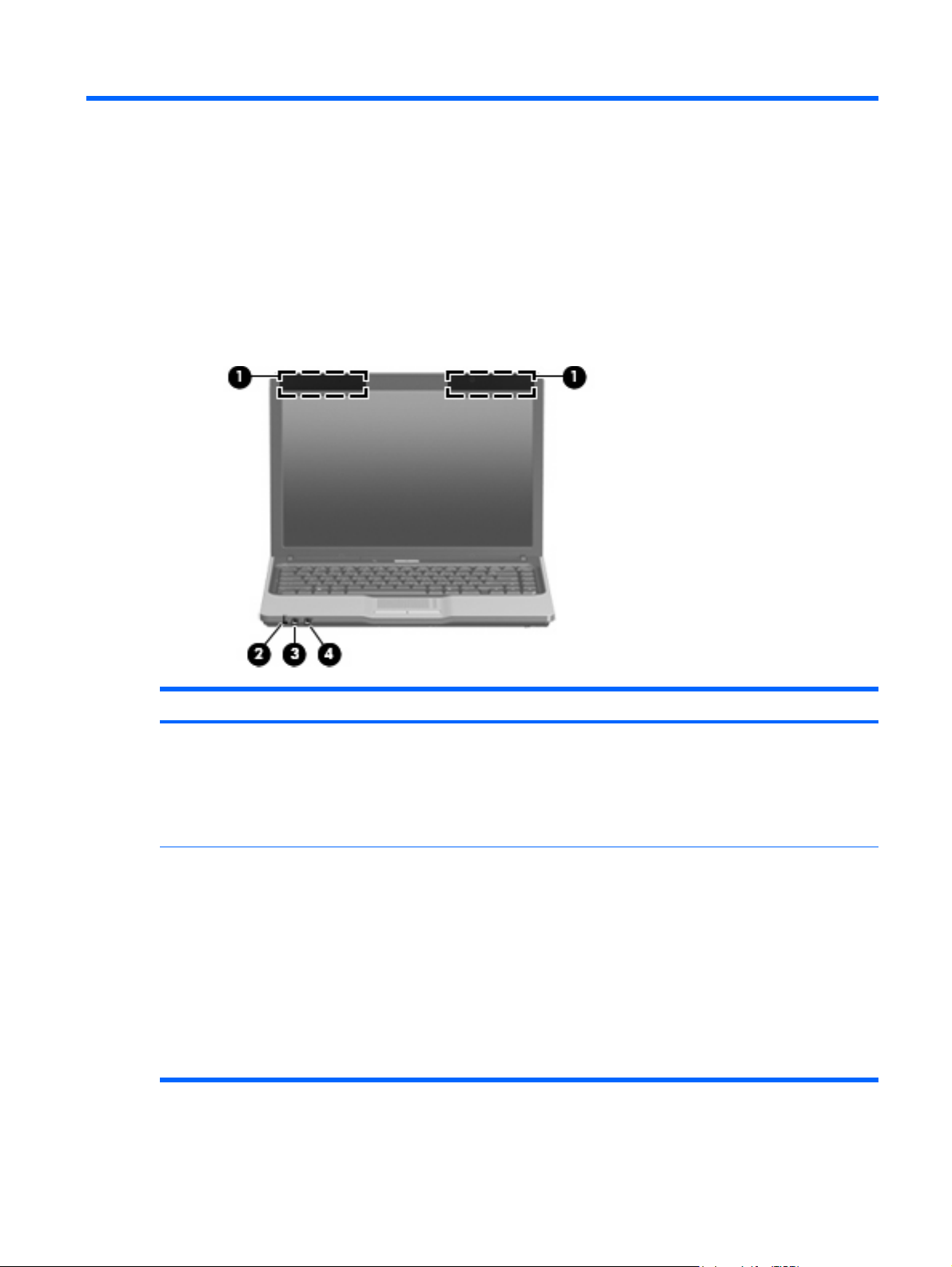
Front components
Item Component Function
Wireless antennae (select models only) Send and receive signals from one or more wireless devices. These
(1)
(2)
Battery light
antennae are not visible from the outside of the computer.
NOTE: To see wireless regulatory notices, refer to the section of
the Regulatory, Safety and Environmental Notices that applies to
your country or region. These notices are located in Help and
Support.
Amber: A battery is charging.
●
Green: A battery is close to full charge capacity.
●
Blinking amber: A battery that is the only available power
●
source has reached a low battery level. When the battery
reaches a critical battery level, the battery light begins to blink
rapidly.
Off: If the computer is plugged into an external power source,
●
the light turns off when all batteries in the computer are fully
charged. If the computer is not plugged into an external power
source, the light stays off until the battery reaches a low battery
level.
Front components 5
Page 14

Item Component Function
Audio-out (headphone) jack Produces sound when connected to optional stereo speakers,
(3)
Audio-in (microphone) jack Connects an optional computer headset microphone, stereo array
(4)
Top components
Buttons and lights
headphones, ear buds, a headset, or television audio.
microphone, or monaural microphone.
Item Component Function
Caps lock light On: Caps lock is on.
(1)
Internal display switch Turns off the display if the display is closed while the power is on.
(2)
Wireless button (select models only) Turns the wireless feature on or off, but does not create a wireless
(3)
(4)
(5)
Wireless light (select models only) ● On: An integrated wireless device, such as a wireless local
Power button*
connection.
NOTE: A wireless network must be set up in order to establish a
wireless connection.
area network (WLAN) device, the HP Broadband Wireless
Module, and.or a Bluetooth® device, is on.
Off: All wireless devices are turned off.
●
When the computer is off, press the button to turn on the
●
computer.
When the computer is on, press the button to initiate the Sleep
●
state.
6Chapter 2 External component identification
Page 15
Item Component Function
● When the computer is in the Sleep state, press the button briefly
to exit the Sleep state.
When the computer is in Hibernation, press the button briefly
●
to exit Hibernation.
If the computer has stopped responding and Windows shutdown
procedures cannot be used, press and hold the power button for at
least 5 seconds to turn off the computer.
To learn more about your power settings, select Start > Control
Panel > System and Maintenance > Power Options.
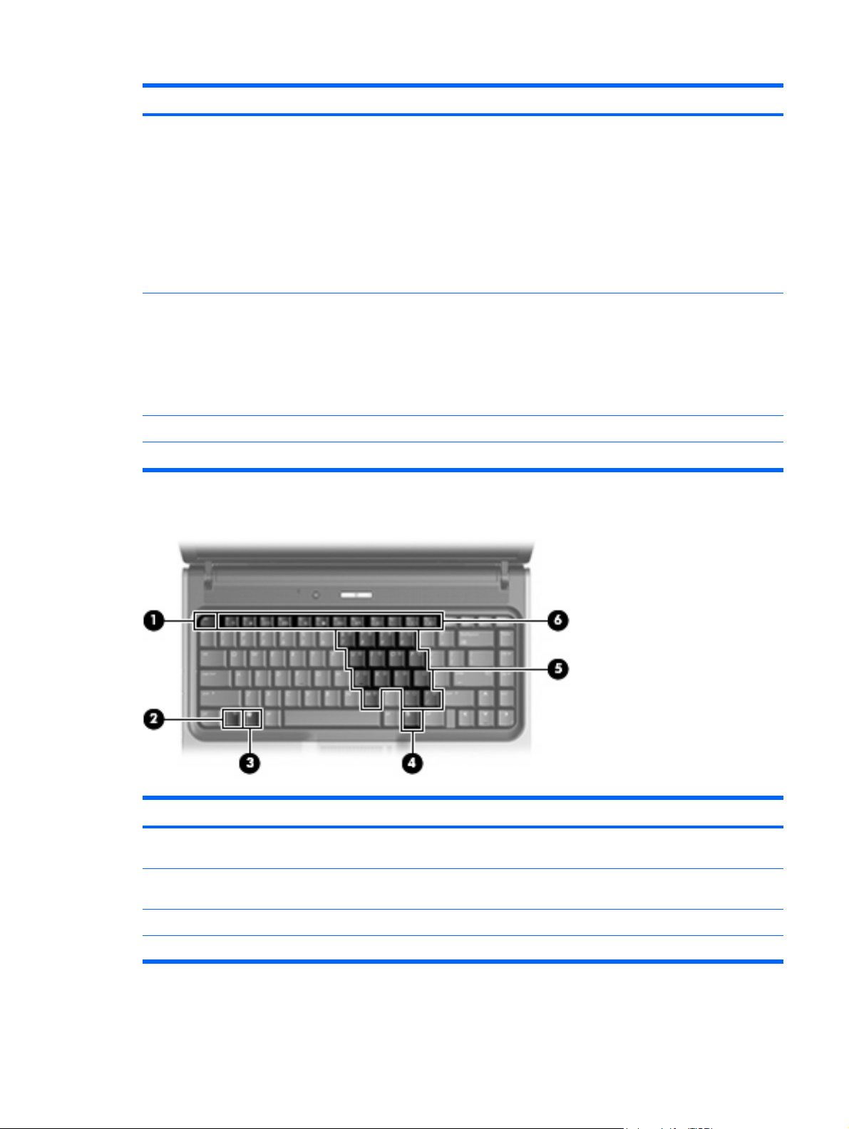
Keys
Power light
(6)
Speaker Produces sound.
(7)
*This table describes factory settings. For information about changing factory settings, refer to the user guides in Help and Support.
On: The computer is on.
●
Blinking: The computer is in the Sleep state.
●
Blinking rapidly: An AC adapter with a higher power rating
●
should be connected.
Off: The computer is off or in Hibernation.
●
Item Component Function
esc key Displays system information when pressed in combination with the
(1)
(2)
(3)
(4)
fn key Executes frequently used system functions when pressed in
Windows logo key Displays the Windows Start menu.
Windows applications key Displays a shortcut menu for items beneath the pointer.
fn key.
combination with a function key or the esc key.
Top components 7
Page 16
Item Component Function
Embedded numeric keypad keys Can be used like the keys on an external numeric keypad.
(5)
Function keys Execute frequently used system functions when pressed in
(6)
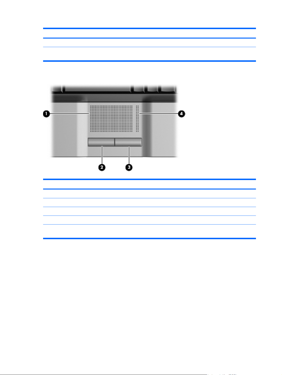
Pointing devices
combination with the fn key.
Item Component Function
TouchPad* Moves the pointer and selects or activates items on the screen.
(1)
Left TouchPad button* Functions like the left button on an external mouse.
(2)
Right TouchPad button* Functions like the right button on an external mouse.
(3)
TouchPad scroll zone* Scrolls up or down.
(4)
*This table describes factory settings. To view or change pointing device preferences, select Start > Control Panel >
Hardware and Sound > Mouse.
8Chapter 2 External component identification
Page 17
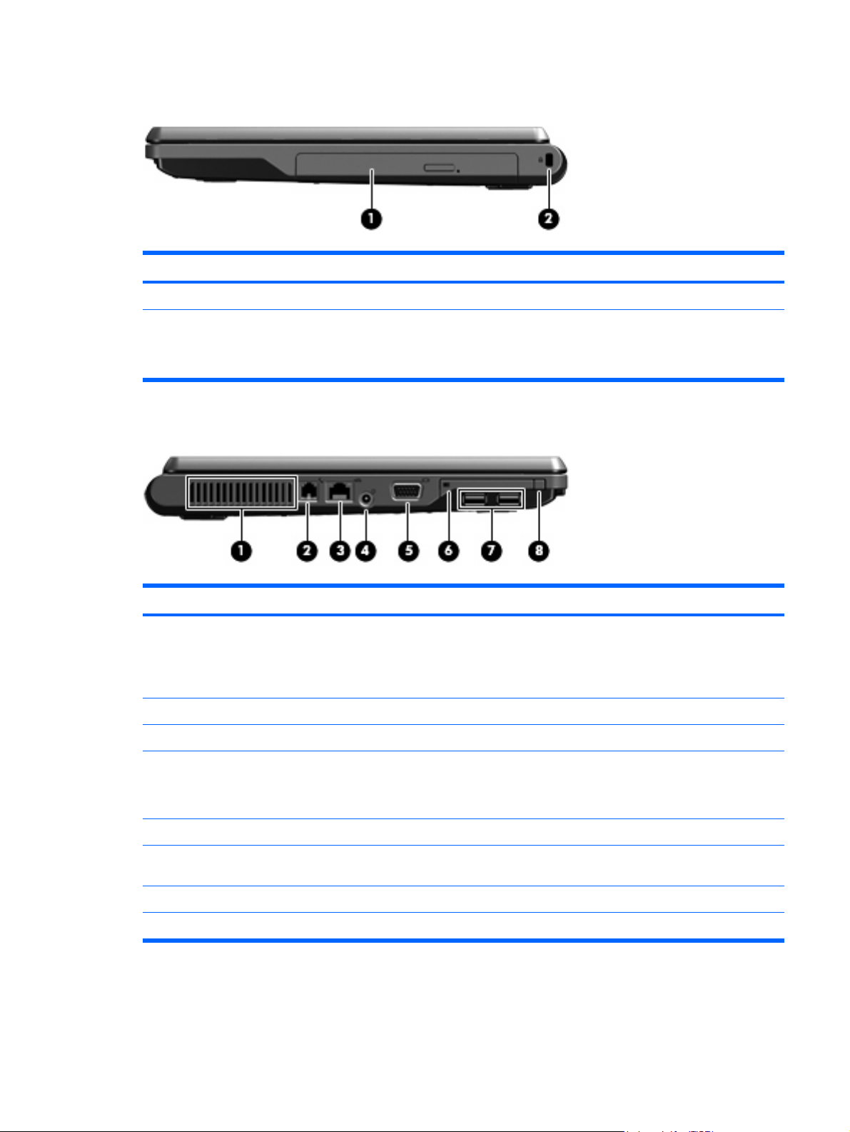
Right-side components
Item Component Function
Optical drive Reads an optical disc.
(1)
Security cable slot Attaches an optional security cable to the computer.
(2)
Left-side components
NOTE: The security cable is designed to act as a deterrent, but it
may not prevent the computer from being mishandled or stolen.
Item Component Function
Vent Enables airflow to cool internal components.
(1)
NOTE: The computer fan starts up automatically to cool internal
components and prevent overheating. It is normal for the internal fan
to cycle on and off during routine operation.
RJ-11 (modem) jack (select models only) Connects a modem cable.
(2)
RJ-45 (network) jack Connects a network cable.
(3)
Power connector Connects an AC adapter.
(4)
NOTE: The HP 520 Notebook PC does not support Smart AC
adapter technology.
External monitor port Connects an optional VGA external monitor or projector.
(5)
PC Card slot Supports optional Type I or Type II 32-bit (CardBus) or 16-bit PC
(6)
(7)
(8)
USB ports (2) Connect an optional USB device.
PC Card eject button Ejects the PC Card from the PC Card slot.
Cards.
Right-side components 9
Page 18
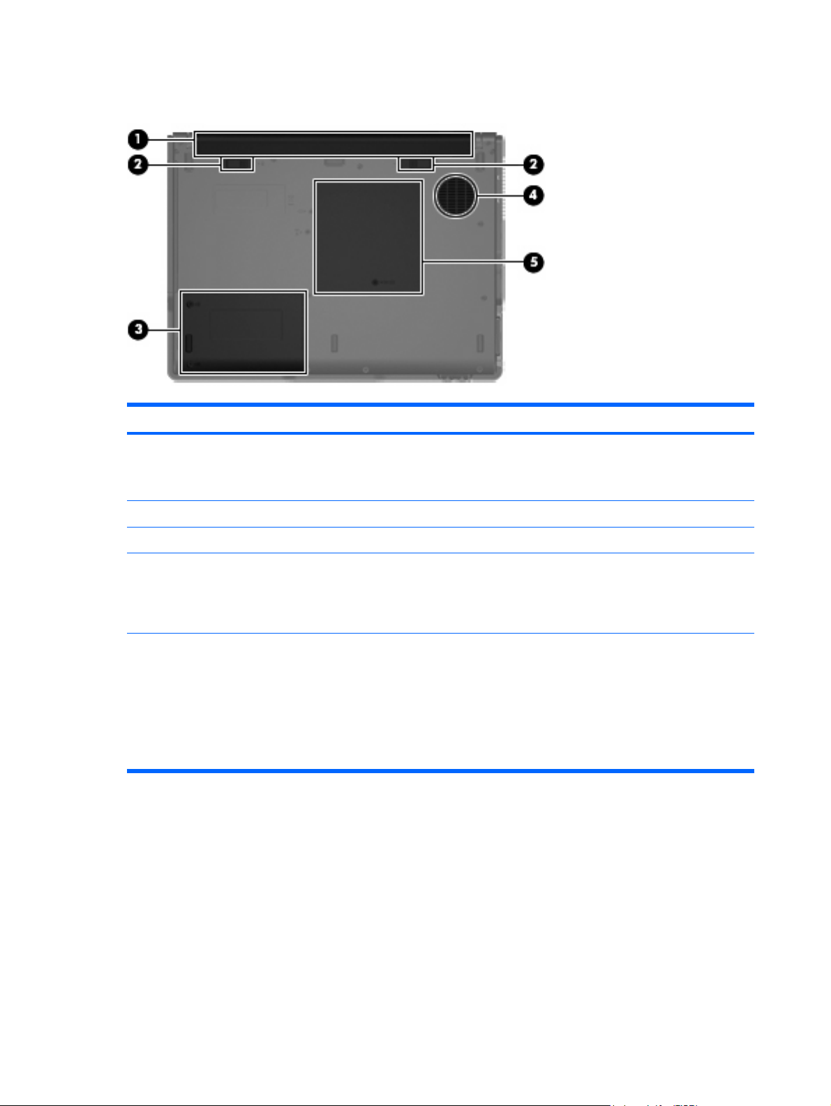
Bottom components
Item Component Function
Battery bay Holds the battery.
(1)
NOTE: The HP 520 Notebook PC does not support Smart Battery
technology.
(2)
(3)
(4)
(5)
Battery release latches (2) Release the battery from the battery bay.
Hard drive bay Holds the hard drive.
Vent Enables airflow to cool internal components.
NOTE: The computer fan starts up automatically to cool internal
components and prevent overheating. It is normal for the internal fan
to cycle on and off during routine operation.
Memory/WLAN module compartment Contains the memory module slot.
CAUTION: To prevent an unresponsive system, replace the
wireless module only with a wireless module authorized for use in
the computer by the governmental agency that regulates wireless
devices in your country or region. If you replace the module and then
receive a warning message, remove the module to restore computer
functionality, and then contact technical support through Help and
Support.
10 Chapter 2 External component identification
Page 19
3
Illustrated parts catalog
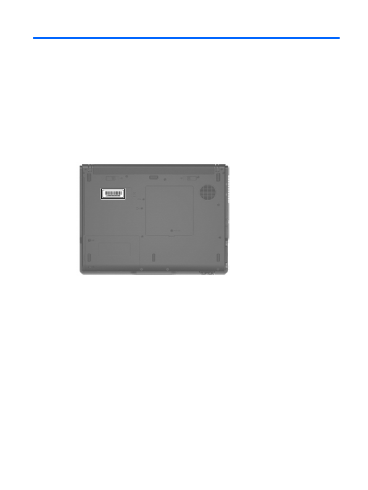
Serial number location
When ordering parts or requesting information, provide the computer serial number and model number
located on the bottom of the computer.
Serial number location 11
Page 20
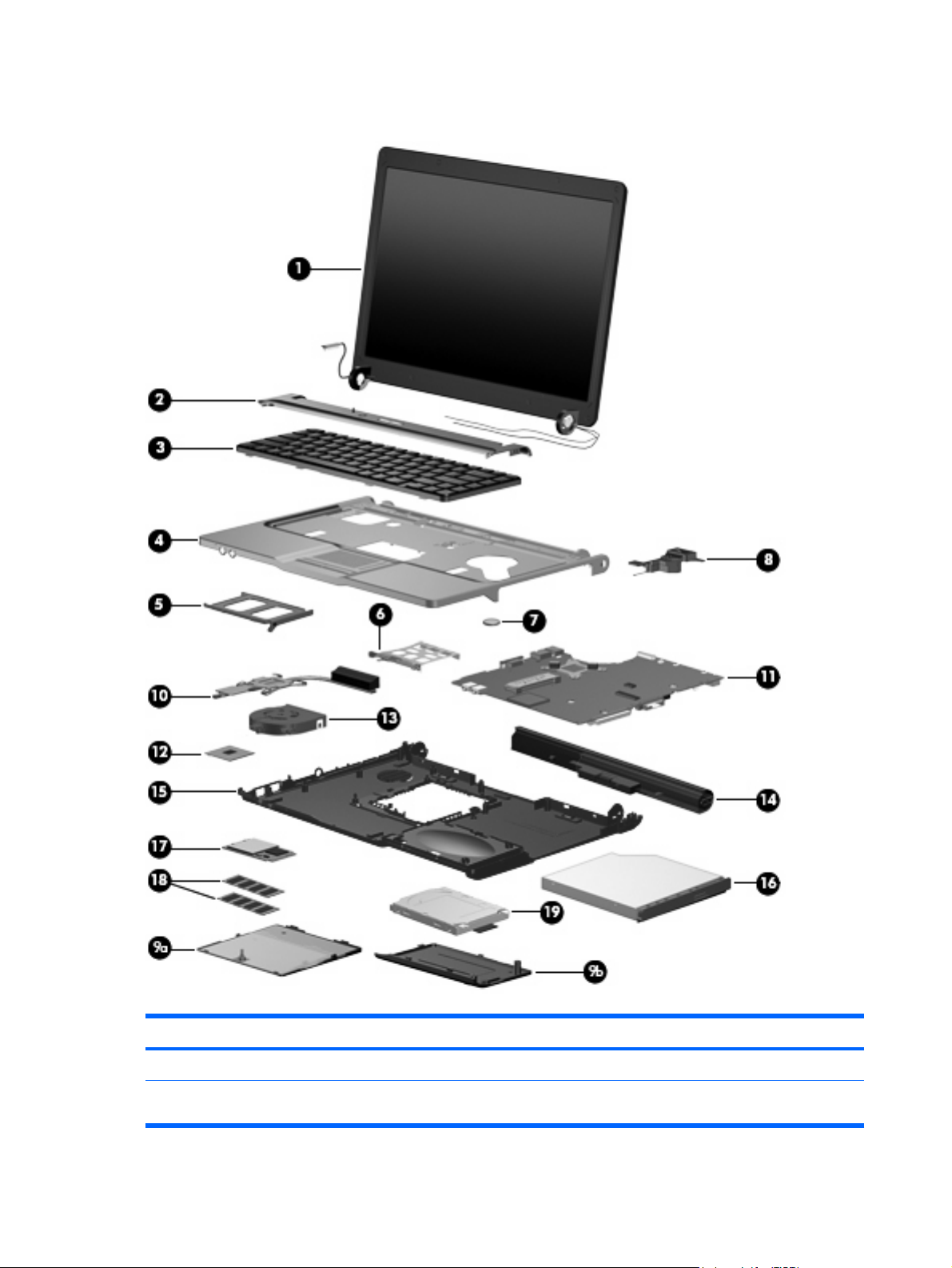
Computer major components
Item Description Spare part number
(1) Display assemblies
14.1-inch, WXGA BrightView display assembly for use only with computer models with
wireless LAN capability (includes wireless antenna transceivers and cables)
12 Chapter 3 Illustrated parts catalog
448328-001
Page 21

Item Description Spare part number
14.1-inch, WXGA BrightView display assembly for use only with computer models without
(2) Switch covers
For use only with computer models without wireless LAN capability 438560-001
(3) Keyboards
The Czech Republic 438531-221
The Netherlands and Europe 438531-021
France 438531-051
Greece 438231-151
Hungary 438231-211
Israel 438531-BB1
Japan 438531-291
Korea 438531-AD1
Latin America 438231-161
wireless LAN capability
For use only with computer models with wireless LAN capability (includes wireless button
and wireless light)
Brazil 438531-201
448327-001
438561-001
Poland 438231-241
Russia 438231-251
Saudi Arabia 438231-171
Slovakia 438231-231
Slovenia 438231-BA1
South Africa 438231-AR1
Thailand 438231-281
Turkey 438231-141
The United Kingdom 438231-031
The United States 438231-001
(4) Top cover (includes TouchPad and TouchPad cable)
(5) PC Card slot bezel
(6) PC Card assembly
(7) RTC battery
(8) Speaker
TouchPad cable (not illustrated)
438522-001
438562-001
438527-001
438551-001
438556-001
438559-001
Plastics/Hardware Kit
448341-001
Computer major components 13
Page 22

Item Description Spare part number
(9a)
(9b)
(10) Heat sink (includes thermal material)
(11) System boards
For use only with computer models with Intel Celeron M processors and WLAN capability 448337-001
For use only with computer models without WLAN capability 448338-001
(12) Processors (include thermal material)
Intel Core Solo T1300 1.66-GHz processor 448325-001
Intel Core Duo T2300E 1.66-GHz processor 448324-001
Intel Core Duo T2300 1.66-GHz processor 448323-001
Intel Celeron M 420 1.60-GHz processor 448322-001
Intel Celeron M 410 1.46-GHz processor 448321-001
(13) Fan assembly
(14) 4-cell, 2.2-Ah, 32-Wh Battery
Memory/WLAN module compartment cover (includes 1 captive screw, secured by a C
clip)
Hard drive cover (includes 2 captive screws, secured by C clips)
For use only with computer models with Intel Core processors and WLAN capability 448339-001
Intel Core Solo T1400 1.83-GHz processor 448326-001
448336-001
438528-001
438518-001
(15) Base enclosure (includes 6 rubber feet, not illustrated)
(16) Optical drives (include bezel and optical drive bracket)
DVD/CD-RW Combo Drive 438524-001
(17) WLAN modules
802.11a/b/g WLAN modules:
Rubber Feet Kit (includes 6 rubber feet, not illustrated)
DVD±RW and CD-RW Super-Multi Double-Layer Combo Drive 438523-001
For use in Antigua and Barbuda, Argentina, Australia, the Bahamas, Barbados,
●
Brunei, Canada, Chile, the Dominican Republic, Guam, Guatemala, Hong Kong,
India, Indonesia, Malaysia, Mexico, New Zealand, Panama, Paraguay, Saudi
Arabia, Taiwan, the United States, and Vietnam
For use in Aruba, Austria, Azerbaijan, Bahrain, Belgium, Bermuda, Brazil, Bulgaria,
●
the Cayman Islands, Colombia, Croatia, Cyprus, the Czech Republic, Denmark,
Egypt, El Salvador, Estonia, Finland, France, Georgia, Germany, Greece, Hungary,
Iceland, Ireland, Italy, Jordan, Latvia, Lebanon, Liechtenstein, Lithuania, Luxembourg,
Malta, Monaco, the Netherlands, Norway, Oman, the Philippines, Poland, Portugal,
Romania, Russia, Serbia and Montenegro, Singapore, Slovakia, Slovenia, South
Africa, Spain, Sri Lanka, Sweden, Switzerland, Turkey, the United Kingdom, and
Uzbekistan
For use in Ecuador, Haiti, Honduras, Pakistan, the People's Republic of China, Peru,
●
Qatar, South Korea, Uruguay, and Venezuela
438517-001
438557-001
407576-001
407576-002
407576-003
802.11b/g WLAN modules:
For use in Japan
●
14 Chapter 3 Illustrated parts catalog
407576-291
Page 23

Item Description Spare part number
● For use in Canada and the United States 407107-001
(18) Memory modules (667-MHz, PC2-5300, 1-DIMM
For use in all countries or regions except Brazil:
● 256-MB 447517-001
For use only in Brazil:
● 512-MB 448331-001
For use in Algeria, Andorra, Argentina, Australia, Austria, Bahrain, Bangladesh,
●
Belarus, Belgium, Bolivia, Brazil, Brunei, Bulgaria, Chile, Colombia, Costa Rica,
Croatia, Cyprus, Czech Republic, Denmark, Ecuador, Egypt, El Salvador, Estonia,
Finland, France, Germany, Gibraltar, Greece, Guatemala, Honduras, Hong Kong,
Hungary, Iceland, India, Indonesia, Ireland, Israel, Italy, Jordan, Kuwait, Latvia,
Lebanon, Liberia, Liechtenstein, Lithuania, Luxembourg, Macedonia, Malaysia,
Mexico, Morocco, Netherlands, New Zealand, Nicaragua, Norway, Oman,
Pakistan, Panama, Paraguay, People's Republic of China, Peru, Philippines, Poland,
Portugal, Qatar, Romania, Russia, Saudi Arabia, Singapore, Slovakia, Slovenia,
South Africa, South Korea, Spain, Sri Lanka, Sweden, Switzerland, Taiwan,
Thailand, Tunisia, Turkey, Ukraine, United Arab Emirates, United Kingdom, Uruguay,
Venezuela, Vietnam, and Yemen
For use in Japan
●
1024-MB
●
512-MB
●
1024-MB
●
407107-002
407107-291
409060-001
447518-001
448329-001
(19) Hard drives (include hard drive bracket and connector)
120 GB, 5400-rpm 435775-001
80 GB, 5400-rpm 435773-001
●
256-MB
448330-001
Computer major components 15
Page 24
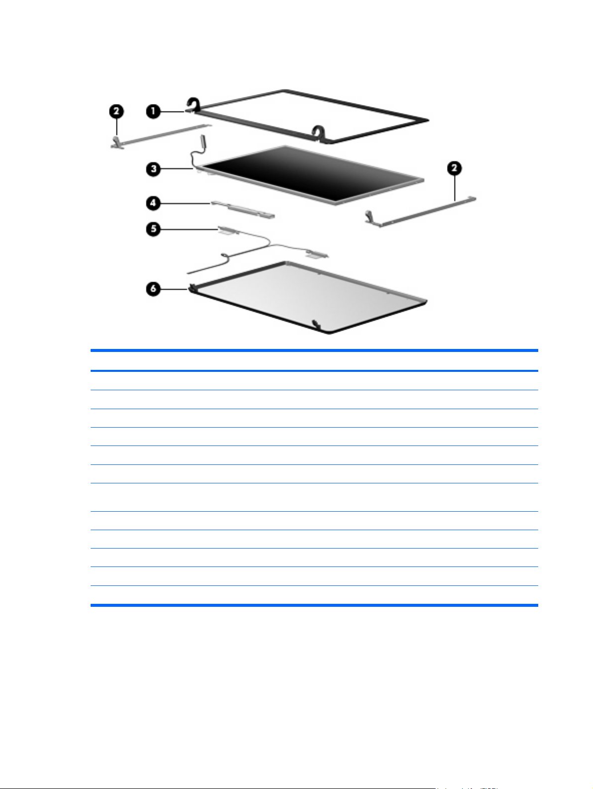
Display assembly components
Item Description Spare part number
(1) Display bezel
(2) Display Bracket/Hinge Kit
(3) 14.1-inch, WXGA, BrightView display panel
(4) Display inverter
(5) Wireless Antenna Kit (includes transceivers and cables)
(6) Display enclosures
For use only with computer models without wireless LAN capability (includes logo) 438538-001
For use only with computer models with wireless LAN capability (includes logo and wireless
antenna transceivers and cables)
Display Cable Kit (not illustrated)
Display Label Kit (not illustrated)
Display Screw Kit (not illustrated)
Display Screw Cover Kit (not illustrated)
438535-001
448335-001
448333-001
448332-001
438516-001
438539-001
448334-001
448340-001
438543-001
438542-001
16 Chapter 3 Illustrated parts catalog
Page 25
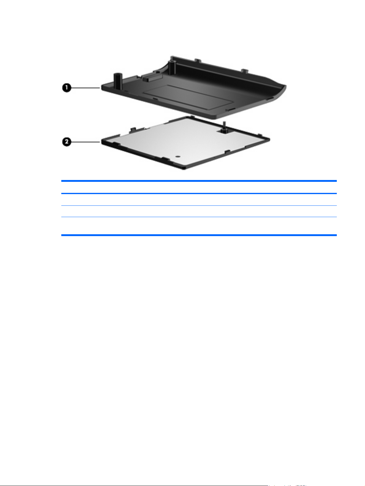
Plastics/Hardware Kit
Item Description Spare part number
(1)
(2)
Plastics/Hardware Kit
Hard drive cover (includes 2 captive screws, secured by C clips)
Memory/WLAN module compartment cover (includes 1 captive screw, secured by a C
clip)
448341-001
Plastics/Hardware Kit 17
Page 26
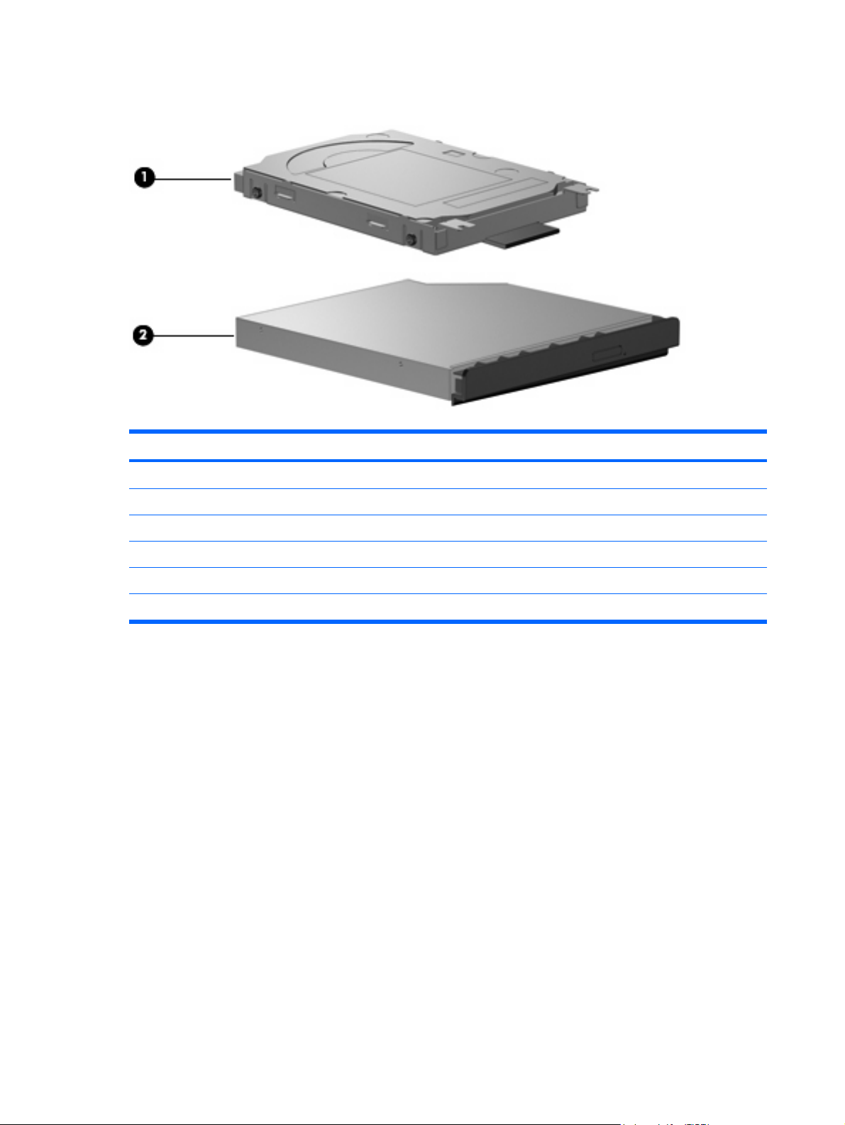
Mass storage devices
Item Description Spare part number
(1) Hard drives (include frame and connector)
120-GB, 5400-rpm 435775-001
80-GB, 5400-rpm 435773-001
(2) Optical drives (include bezel and bracket)
DVD±RW and CD-RW Super-Multi, Double-Layer Combo Drive 438523-001
DVD/CD-RW Combo Drive 438524-001
18 Chapter 3 Illustrated parts catalog
Page 27

Miscellaneous parts
Description Spare part number
65-watt AC adapter
Power cords:
Australia
Brazil 350055-201
Denmark 350055-081
Europe 350055-021
French Canada 350055-DB1
Israel 350055-BB1
Italy 350055-061
Japan 350055-291
Korea 350055-AD1
People's Republic of China 350055-AA1
Switzerland 350055-BG1
The United Kingdom 350055-031
The United States 350055-001
Screw Kit
417220-001
350055-011
438558-001
Phillips PM3.0×3.0 screw
●
Phillips PM2.5×8.0 captive screw
●
Phillips PM2.5×6.0 screw
●
Phillips PM2.0×9.0 screw
●
Phillips PM2.0×3.0 screw
●
Miscellaneous parts 19
Page 28

Sequential part number listing
Spare part
number
350055-001 Power cord use in the United States
350055-011 Power cord for use in Australia
350055-021 Power cord for use in Europe
350055-031 Power cord for use in the United Kingdom
350055-061 Power cord for use in Italy
350055-081 Power cord for use in Denmark
350055-201 Power cord for use in Brazil
350055-291 Power cord for use in Japan
350055-AA1 Power cord for use in the People’s Republic of China
350055-AD1 Power cord for use in Korea
350055-BB1 Power cord for use in Israel
350055-BG1 Power cord for use in Switzerland
350055-DB1 Power cord for use in French Canada
407107-001 802.11b/g WLAN module for use in Canada and the United States
407107-002 802.11b/g WLAN module for use in Algeria, Andorra, Argentina, Australia, Austria, Bahrain,
Description
Bangladesh, Belarus, Belgium, Bolivia, Brazil, Brunei, Bulgaria, Chile, Colombia, Costa Rica, Croatia,
Cyprus, Czech Republic, Denmark, Ecuador, Egypt, El Salvador, Estonia, Finland, France, Germany,
Gibraltar, Greece, Guatemala, Honduras, Hong Kong, Hungary, Iceland, India, Indonesia, Ireland, Israel,
Italy, Jordan, Kuwait, Latvia, Lebanon, Liberia, Liechtenstein, Lithuania, Luxembourg, Macedonia,
Malaysia, Mexico, Morocco, Netherlands, New Zealand, Nicaragua, Norway, Oman, Pakistan,
Panama, Paraguay, People's Republic of China, Peru, Philippines, Poland, Portugal, Qatar, Romania,
Russia, Saudi Arabia, Singapore, Slovakia, Slovenia, South Africa, South Korea, Spain, Sri Lanka,
Sweden, Switzerland, Taiwan, Thailand, Tunisia, Turkey, Ukraine, United Arab Emirates, United Kingdom,
Uruguay, Venezuela, Vietnam, and Yemen
407107-291 802.11b/g WLAN module for use in Japan
407576-001 802.11a/b/g WLAN module for use in Antigua and Barbuda, Argentina, Australia, the Bahamas,
Barbados, Brunei, Canada, Chile, the Dominican Republic, Guam, Guatemala, Hong Kong, India,
Indonesia, Malaysia, Mexico, New Zealand, Panama, Paraguay, Saudi Arabia, Taiwan, the United
States, and Vietnam
407576-002 802.11a/b/g WLAN module for use in Aruba, Austria, Azerbaijan, Bahrain, Belgium, Bermuda, Brazil,
407576-003 802.11a/b/g WLAN module for use in Ecuador, Haiti, Honduras, Pakistan, the People's Republic of
407576-291 802.11a/b/g WLAN module for use in Japan
409060-001 1024-MB, 667-MHz, PC2-5300, 1-DIMM memory module for use in all countries and regions except
Bulgaria, the Cayman Islands, Colombia, Croatia, Cyprus, the Czech Republic, Denmark, Egypt, El
Salvador, Estonia, Finland, France, Georgia, Germany, Greece, Hungary, Iceland, Ireland, Italy, Jordan,
Latvia, Lebanon, Liechtenstein, Lithuania, Luxembourg, Malta, Monaco, the Netherlands, Norway, Oman,
the Philippines, Poland, Portugal, Romania, Russia, Serbia and Montenegro, Singapore, Slovakia,
Slovenia, South Africa, Spain, Sri Lanka, Sweden, Switzerland, Turkey, the United Kingdom, and
Uzbekistan
China, Peru, Qatar, South Korea, Uruguay, and Venezuela
Brazil
20 Chapter 3 Illustrated parts catalog
Page 29

Spare part
number
417220-001 65-watt AC adapter
435773-001 80-GB, 5400-rpm hard drive (includes hard drive bracket and connector)
435775-001 120-GB, 5400-rpm hard drive (includes hard drive bracket and connector)
438516-001 Wireless Antenna Kit (includes wireless antenna transceivers and cables)
438517-001 Base enclosure (includes 6 rubber feet)
438518-001 4-cell, 2.2-Ah, 32-Wh Battery
438522-001 Top cover (includes TouchPad and TouchPad cable)
438523-001 DVD±RW and CD-RW Super-Multi Double-Layer Combo Drive (includes bezel and optical drive bracket)
438524-001 DVD/CD-RW Combo Drive (includes bezel and optical drive bracket)
438527-001 PC Card slot bezel
438528-001 Fan assembly
438531-001 Keyboard for use in the United States
438531-021 Keyboard for use in the Netherlands and Europe
438531-031 Keyboard for use in the United Kingdom
438531-051 Keyboard for use in France
Description
438531-141 Keyboard for use in Turkey
438531-151 Keyboard for use in Greece
438531-161 Keyboard for use in Latin America
438531-171 Keyboard for use in Saudi Arabia
438531-201 Keyboard for use in Brazil
438531-211 Keyboard for use in Hungary
438531-221 Keyboard for use in the Czech Republic
438531-231 Keyboard for use in Slovakia
438531-241 Keyboard for use in Poland
438531-251 Keyboard for use in Russia
438531-281 Keyboard for use in Thailand
438531-291 Keyboard for use in Japan
438531-AD1 Keyboard for use in Korea
438531-AR1 Keyboard for use in South Africa
438531-BA1 Keyboard for use in Slovenia
438531-BB1 Keyboard for use in Israel
438535-001 Display bezel
438538-001 Display enclosure for use only with computer models without wireless LAN capability (includes logo)
Sequential part number listing 21
Page 30

Spare part
number
438539-001 Display enclosure for use only with computer models with wireless LAN capability (includes logo and
438542-001 Display Screw Cover Kit
438543-001 Display Screw Kit
438551-001 PC Card assembly
438556-001 RTC battery
438557-001 Rubber Feet Kit
438558-001 Screw Kit
438559-001 Speaker
438560-001 Switch cover for use only with computer models without wireless LAN capability
438561-001 Switch cover for use only with computer models with wireless LAN capability (includes wireless button and
438562-001 TouchPad cable
447517-001 512-MB, 667-MHz, PC2-5300, 1-DIMM memory module for use in all countries and regions except
447518-001 256-MB, 667-MHz, PC2-5300, 1-DIMM memory module for use in all countries and regions except Brazil
Description
wireless antenna transceivers and cables)
wireless light)
Brazil
448321-001 Intel Celeron M 410 1.46-GHz processor
448322-001 Intel Celeron M 420 1.60-GHz processor
448323-001 Intel Core Duo T2300 1.66-GHz processor
448324-001 Intel Core Duo T2300E 1.66-GHz processor
448325-001 Intel Core Solo T1300 1.66-GHz processor
448326-001 Intel Core Solo T1400 1.83-GHz processor
448327-001 14.1-inch, WXGA BrightView display assembly for use only with computer models without wireless LAN
capability
448328-001 14.1-inch, WXGA BrightView display assembly for use only with computer models with WLAN capability
448329-001 1024-MB, 667-MHz, PC2-5300, 1-DIMM memory module for use only in Brazil
448330-001 256-MB, 667-MHz, PC2-5300, 1-DIMM memory module for use only in Brazil
448331-001 512-MB, 667-MHz, PC2-5300, 1-DIMM memory module for use only in Brazil
448332-001 Display inverter
448333-001 14.1-inch, WXGA, BrightView display panel
448334-001 Display Cable Kit
448335-001 Display Bracket/Hinge Kit
(includes wireless antenna transceivers and cables)
448336-001 Heat sink (includes thermal material)
448337-001 For use only with computer models with Intel Celeron M processors and WLAN capability
448338-001 For use only with computer models without WLAN capability
22 Chapter 3 Illustrated parts catalog
Page 31

Spare part
number
448339-001 For use only with computer models with Intel Core processors and WLAN capability
448340-001 Display Label Kit
448341-001 Plastics/Hardware Kit
Description
Sequential part number listing 23
Page 32

24 Chapter 3 Illustrated parts catalog
Page 33

4
Removal and replacement procedures
Preliminary replacement requirements
Tools required
You will need the following tools to complete the removal and replacement procedures:
Magnetic screwdriver
●
Phillips P0 and P1 screwdrivers
●
Flat-bladed screwdriver
●
Service considerations
The following sections include some of the considerations that you should keep in mind during disassembly
and assembly procedures.
NOTE: As you remove each subassembly from the computer, place the subassembly (and all
accompanying screws) away from the work area to prevent damage.
Plastic parts
Using excessive force during disassembly and reassembly can damage plastic parts. Use care when
handling the plastic parts. Apply pressure only at the points designated in the maintenance instructions.
Cables and connectors
CAUTION: When servicing the computer, be sure that cables are placed in their proper locations
during the reassembly process. Improper cable placement can damage the computer.
Cables must be handled with extreme care to avoid damage. Apply only the tension required to unseat
or seat the cables during removal and insertion. Handle cables by the connector whenever possible. In
all cases, avoid bending, twisting, or tearing cables. Be sure that cables are routed in such a way that
they cannot be caught or snagged by parts being removed or replaced. Handle flex cables with extreme
care; these cables tear easily.
Preliminary replacement requirements 25
Page 34

Drive handling
CAUTION: Drives are fragile components that must be handled with care. To prevent damage to the
computer, damage to a drive, or loss of information, observe these precautions:
Before removing or inserting a hard drive, shut down the computer. If you are unsure whether the computer
is off or in Hibernation, turn the computer on, and then shut it down through the operating system.
Before handling a drive, be sure that you are discharged of static electricity. While handling a drive,
avoid touching the connector.
Before removing a diskette drive or optical drive, be sure that a diskette or disc is not in the drive and be
sure that the optical drive tray is closed.
Handle drives on surfaces covered with at least one inch of shock-proof foam.
Avoid dropping drives from any height onto any surface.
After removing a hard drive, an optical drive, or a diskette drive, place it in a static-proof bag.
Avoid exposing a hard drive to products that have magnetic fields, such as monitors or speakers.
Avoid exposing a drive to temperature extremes or liquids.
If a drive must be mailed, place the drive in a bubble pack mailer or other suitable form of protective
packaging and label the package “FRAGILE.”
Grounding guidelines
Electrostatic discharge damage
Electronic components are sensitive to electrostatic discharge (ESD). Circuitry design and structure
determine the degree of sensitivity. Networks built into many integrated circuits provide some protection,
but in many cases, ESD contains enough power to alter device parameters or melt silicon junctions.
A discharge of static electricity from a finger or other conductor can destroy static-sensitive devices or
microcircuitry. Even if the spark is neither felt nor heard, damage may have occurred.
An electronic device exposed to ESD may not be affected at all and can work perfectly throughout a
normal cycle. Or the device may function normally for a while, then degrade in the internal layers,
reducing its life expectancy.
CAUTION: To prevent damage to the computer when you are removing or installing internal
components, observe these precautions:
Keep components in their electrostatic-safe containers until you area ready to install them.
Use nonmagnetic tools.
Before touching an electronic component, discharge static electricity by using the guidelines described in
this section.
Avoid touching pins, leads, and circuitry. Handle electronic components as little as possible.
If you remove a component, place it in an electrostatic-safe container.
The following table shows how humidity affects the electrostatic voltage levels generated by different
activities.
26 Chapter 4 Removal and replacement procedures
Page 35

CAUTION: A product can be degraded by as little as 700 V.
Relative humidity
Event 10% 40% 55%
Walking across carpet 35,000 V 15,000 V 7,500 V
Walking across vinyl floor 12,000 V 5,000 V 3,000 V
Motions of bench worker 6,000 V 800 V 400 V
Removing DIPS from plastic tube 2,000 V 700 V 400 V
Removing DIPS from vinyl tray 11,500 V 4,000 V 2,000 V
Removing DIPS from Styrofoam 14,500 V 5,000 V 3,500 V
Removing bubble pack from PCB 26,500 V 20,000 V 7,000 V
Packing PCBs in foam-lined box 21,000 V 11,000 V 5,000 V
Packaging and transporting guidelines
Follow these grounding guidelines when packaging and transporting equipment:
Typical electrostatic voltage levels
To avoid hand contact, transport products in static-safe tubes, bags, or boxes.
●
Protect ESD-sensitive parts and assemblies with conductive or approved containers or packaging.
●
Keep ESD-sensitive parts in their containers until the parts arrive at static-free workstations.
●
Place items on a grounded surface before removing items from their containers.
●
Always be properly grounded when touching a component or assembly.
●
Store reusable ESD-sensitive parts from assemblies in protective packaging or nonconductive foam.
●
Use transporters and conveyors made of antistatic belts and roller bushings. Be sure that mechanized
●
equipment used for moving materials is wired to ground and that proper materials are selected to
avoid static charging. When grounding is not possible, use an ionizer to dissipate electric charges.
Workstation guidelines
Follow these grounding workstation guidelines:
Cover the workstation with approved static-shielding material.
●
Use a wrist strap connected to a properly grounded work surface and use properly grounded tools
●
and equipment.
Use conductive field service tools, such as cutters, screwdrivers, and vacuums.
●
When fixtures must directly contact dissipative surfaces, use fixtures made only of static-safe
●
materials.
Keep the work area free of nonconductive materials, such as ordinary plastic assembly aids and
●
Styrofoam.
Preliminary replacement requirements 27
Page 36

Handle ESD-sensitive components, parts, and assemblies by the case or PCM laminate. Handle these
●
items only at static-free workstations.
Avoid contact with pins, leads, or circuitry.
●
Turn off power and input signals before inserting or removing connectors or test equipment.
●
Equipment guidelines
Grounding equipment must include either a wrist strap or a foot strap at a grounded workstation.
When seated, wear a wrist strap connected to a grounded system. Wrist straps are flexible straps
●
with a minimum of one megohm ±10% resistance in the ground cords. To provide proper ground,
wear a strap snugly against the skin at all times. On grounded mats with banana-plug connectors,
use alligator clips to connect a wrist strap.
When standing, use foot straps and a grounded floor mat. Foot straps (heel, toe, or boot straps) can
●
be used at standing workstations and are compatible with most types of shoes or boots. On
conductive floors or dissipative floor mats, use foot straps on both feet with a minimum of one megohm
resistance between the operator and ground. To be effective, the conductive strips must be worn in
contact with the skin.
The following grounding equipment is recommended to prevent electrostatic damage:
Antistatic tape
●
Antistatic smocks, aprons, and sleeve protectors
●
Conductive bins and other assembly or soldering aids
●
Nonconductive foam
●
Conductive tabletop workstations with ground cords of one megohm resistance
●
Static-dissipative tables or floor mats with hard ties to the ground
●
Field service kits
●
Static awareness labels
●
Material-handling packages
●
Nonconductive plastic bags, tubes, or boxes
●
Metal tote boxes
●
Electrostatic voltage levels and protective materials
●
The following table lists the shielding protection provided by antistatic bags and floor mats.
Material Use Voltage protection level
Antistatic plastic Bags 1,500 V
Carbon-loaded plastic Floor mats 7,500 V
Metallized laminate Floor mats 5,000 V
28 Chapter 4 Removal and replacement procedures
Page 37

Unknown user password
If the computer you are servicing has an unknown user password, follow these steps to clear the password.
NOTE: These steps also clear CMOS.
Before disassembling the computer, follow these steps:
Shut down the computer. If you are unsure whether the computer is off or in Hibernation, turn the
1.
computer on, and then shut it down through the operating system.
Disconnect all external devices connected to the computer.
2.
Disconnect the power from the computer by first unplugging the power cord from the AC outlet and
3.
then unplugging the AC adapter from the computer.
Remove the battery (see
4.
Remove the real-time clock (RTC) battery (see
5.
Wait approximately 5 minutes.
6.
Replace the RTC battery and reassemble the computer.
7.
Connect AC power to the computer. Do not reinsert any batteries at this time.
8.
Turn on the computer.
9.
All passwords and all CMOS settings have been cleared.
Battery on page 31).
RTC battery on page 52).
Preliminary replacement requirements 29
Page 38

Component replacement procedures
This chapter provides removal and replacement procedures.
There are as many as 59 screws, in 7 different sizes, that must be removed, replaced, or loosened when
servicing the computer. Make special note of each screw and screw lock size and location during removal
and replacement.
Serial number
Report the computer serial number to HP when requesting information or ordering spare parts. The serial
number is located on the bottom of the computer.
30 Chapter 4 Removal and replacement procedures
Page 39
Battery
Description Spare part number
4-cell, 2.2-Ah, 32-Wh Battery 438518-001
Before disassembling the computer, follow these steps:
Shut down the computer. If you are unsure whether the computer is off or in Hibernation, turn the
1.
computer on, and then shut it down through the operating system.
Disconnect all external devices connected to the computer.
2.
Disconnect the power from the computer by first unplugging the power cord from the AC outlet and
3.
then unplugging the AC adapter from the computer.
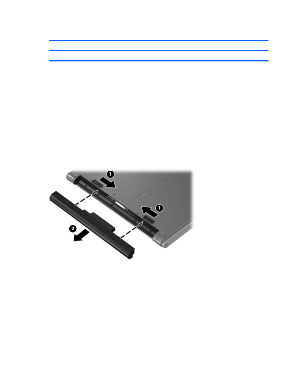
Remove the battery:
Turn the computer upside down on a flat surface, with the rear panel toward you.
1.
2. Slide the battery release latches (1) to release the battery.
3. Remove the battery (2).
Install the battery by inserting it into the battery bay until you hear a click.
Component replacement procedures 31
Page 40

Hard drive
Description Spare part number
120-GB, 5400-rpm 435775-001
80-GB, 5400-rpm 435773-001
Before disassembling the computer, follow these steps:
Shut down the computer. If you are unsure whether the computer is off or in Hibernation, turn the
1.
computer on, and then shut it down through the operating system.
Disconnect all external devices connected to the computer.
2.
Disconnect the power from the computer by first unplugging the power cord from the AC outlet and
3.
then unplugging the AC adapter from the computer.
Remove the battery (see
4.
Battery on page 31).
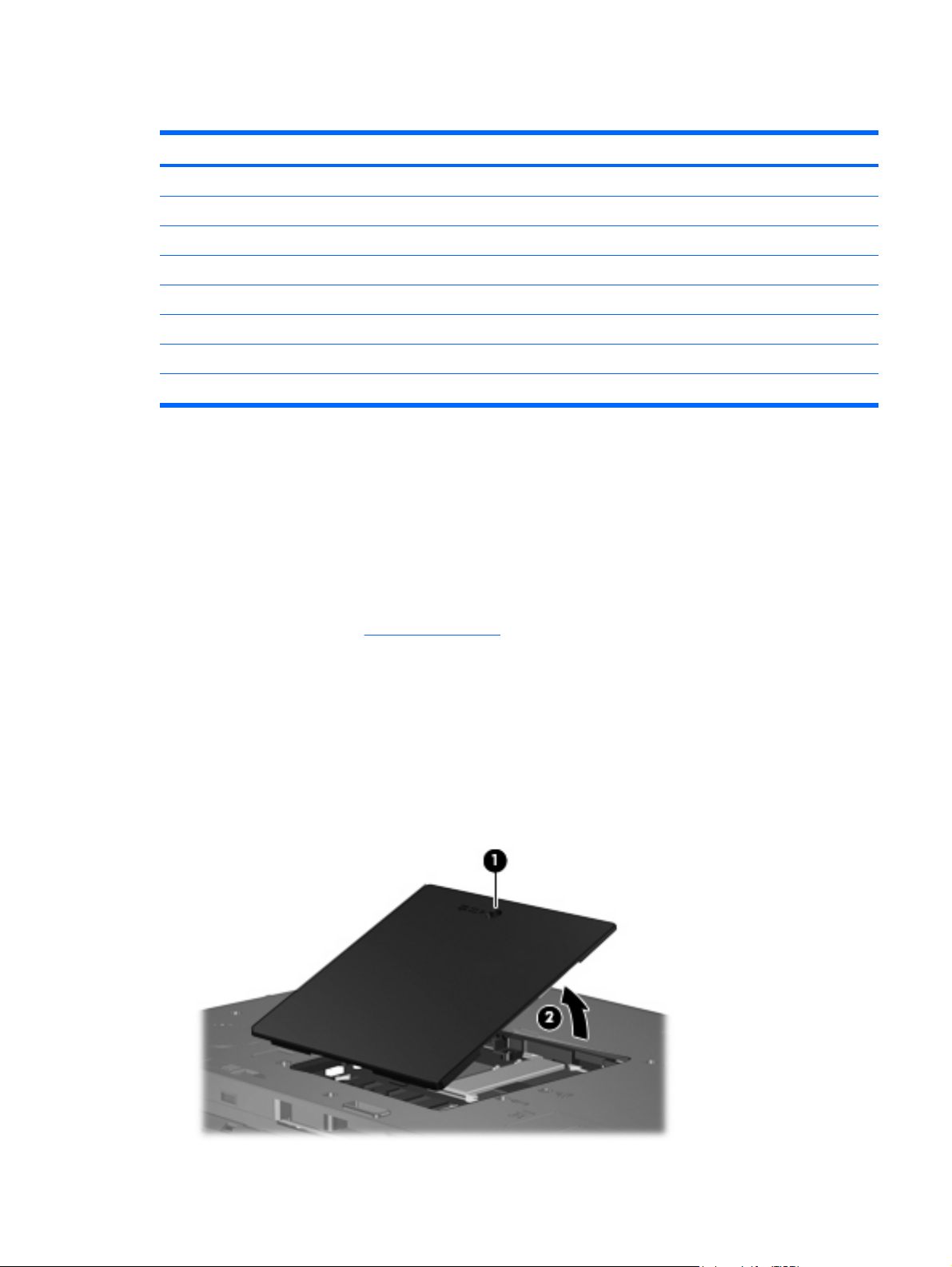
Remove the hard drive:
Position the computer with the front toward you.
1.
2. Loosen the two Phillips PM2.5×8.0 screws (1) that secure the hard drive cover to the computer.
3. Lift the left side of the hard drive cover (2), swing it to right, and remove the cover. The hard drive
cover is included in the Plastics/Hardware Kit, spare part number 448341-001.
4. Grasp the Mylar tab (1) on the hard drive and slide the hard drive (2) to the left to disconnect it
from the system board.
32 Chapter 4 Removal and replacement procedures
Page 41

5. Remove the hard drive (3) from the hard drive bay.
If it is necessary to replace the hard drive bracket, remove the four Phillips PM3.0×3.0 hard drive
6.
bracket screws (1) from each side of the hard drive.
7. Lift the bracket (2) straight up to remove it from the hard drive.
Reverse this procedure to reassemble and install the hard drive.
Component replacement procedures 33
Page 42

Computer feet
Description Spare part number
Rubber Feet Kit 438557-001
The computer feet are adhesive-backed rubber pads. There are 6 rubber feet. The feet attach to the base
enclosure in the locations illustrated below.
34 Chapter 4 Removal and replacement procedures
Page 43
Memory module
Description Spare part number
For use in all countries and regions except Brazil
1024-MB, PC2-5300, 1-DIMM
512-MB, PC2-5300, 1-DIMM 447518-001
256-MB, PC2-5300, 1-DIMM 447517-001
For use only in Brazil
1024-MB, PC2-5300, 1-DIMM
512-MB, PC2-5300, 1-DIMM 448331-001
256-MB, PC2-5300, 1-DIMM 448330-001
409060-001
448329-001
Before removing the memory module, follow these steps:
Shut down the computer. If you are unsure whether the computer is off or in Hibernation, turn the
1.
computer on, and then shut it down through the operating system.
Disconnect all external devices connected to the computer.
2.
Disconnect the power from the computer by first unplugging the power cord from the AC outlet and
3.
then unplugging the AC adapter from the computer.
Remove the battery (see
4.
Battery on page 31).
Remove the external memory module:
Position the computer with the rear panel toward you.
1.
2. Loosen the Phillips PM2.5×8.0 screw (1) that secures the memory/WLAN module compartment
cover to the computer.
3. Lift the front edge of the cover (2), swing it toward you, and remove the cover. The memory/WLAN
module compartment cover is included in the Plastics/Hardware Kit, spare part number
448341-001.
Component replacement procedures 35
Page 44

4. Spread the retaining tabs (1) on each side of the memory module slot to release the memory module.
(The edge of the module opposite the slot rises away from the computer.)
5. Remove the memory module (2) by pulling the module away from the slot at an angle.
NOTE: Memory modules are designed with a notch (3) to prevent incorrect installation into the
memory module slot.
Reverse this procedure to install a memory module.
36 Chapter 4 Removal and replacement procedures
Page 45

WLAN module
Description Spare part number
802.11a/b/g WLAN modules:
For use in Antigua and Barbuda, Argentina, Australia, the Bahamas, Barbados, Brunei, Canada,
●
Chile, the Dominican Republic, Guam, Guatemala, Hong Kong, India, Indonesia, Malaysia,
Mexico, New Zealand, Panama, Paraguay, Saudi Arabia, Taiwan, the United States, and
Vietnam
For use in Aruba, Austria, Azerbaijan, Bahrain, Belgium, Bermuda, Brazil, Bulgaria, the Cayman
●
Islands, Colombia, Croatia, Cyprus, the Czech Republic, Denmark, Egypt, El Salvador, Estonia,
Finland, France, Georgia, Germany, Greece, Hungary, Iceland, Ireland, Italy, Jordan, Latvia,
Lebanon, Liechtenstein, Lithuania, Luxembourg, Malta, Monaco, the Netherlands, Norway,
Oman, the Philippines, Poland, Portugal, Romania, Russia, Serbia and Montenegro, Singapore,
Slovakia, Slovenia, South Africa, Spain, Sri Lanka, Sweden, Switzerland, Turkey, the United
Kingdom, and Uzbekistan
For use in Ecuador, Haiti, Honduras, Pakistan, the People's Republic of China, Peru, Qatar, South
●
Korea, Uruguay, and Venezuela
● For use in Japan 407576-291
802.11b/g WLAN modules:
For use in Canada and the United States
●
● For use in For use in Algeria, Andorra, Argentina, Australia, Austria, Bahrain, Bangladesh,
Belarus, Belgium, Bolivia, Brazil, Brunei, Bulgaria, Chile, Colombia, Costa Rica, Croatia,
Cyprus, Czech Republic, Denmark, Ecuador, Egypt, El Salvador, Estonia, Finland, France,
Germany, Gibraltar, Greece, Guatemala, Honduras, Hong Kong, Hungary, Iceland, India,
Indonesia, Ireland, Israel, Italy, Jordan, Kuwait, Latvia, Lebanon, Liberia, Liechtenstein, Lithuania,
Luxembourg, Macedonia, Malaysia, Mexico, Morocco, Netherlands, New Zealand, Nicaragua,
Norway, Oman, Pakistan, Panama, Paraguay, People's Republic of China, Peru, Philippines,
Poland, Portugal, Qatar, Romania, Russia, Saudi Arabia, Singapore, Slovakia, Slovenia, South
Africa, South Korea, Spain, Sri Lanka, Sweden, Switzerland, Taiwan, Thailand, Tunisia, Turkey,
Ukraine, United Arab Emirates, United Kingdom, Uruguay, Venezuela, Vietnam, and Yemen
407576-001
407576-002
407576-003
407107-001
407107-002
For use in Japan 407107-291
●
Before removing the WLAN module, follow these steps:
Shut down the computer. If you are unsure whether the computer is off or in Hibernation, turn the
1.
computer on, and then shut it down through the operating system.
Disconnect all external devices connected to the computer.
2.
Disconnect the power from the computer by first unplugging the power cord from the AC outlet and
3.
then unplugging the AC adapter from the computer.
Remove the battery (see
4.
Remove the memory/WLAN module compartment cover (see
5.
Battery on page 31).
Memory module on page 35).
Component replacement procedures 37
Page 46

Remove the WLAN module:
1. Disconnect the WLAN antenna cables (1) from the terminals on the WLAN module.
NOTE: The black WLAN antenna cable is connected to the WLAN module “Main” terminal. The
white WLAN antenna cable is connected to the WLAN module “Aux” terminal.
2. Remove the two Phillips PM2.0×4.0 screws (2) that secure the WLAN module to the computer. (The
edge of the module opposite the slot rises away from the computer.)
3. Remove the WLAN module (3) by pulling the module away from the slot at an angle.
NOTE: WLAN modules are designed with a notch (4) to prevent incorrect installation.
Reverse this procedure to install a WLAN module.
38 Chapter 4 Removal and replacement procedures
Page 47

Optical drive
NOTE: All optical drive spare part kits include an optical drive bezel and optical drive bracket.
Description Spare part number
DVD±RW and CD-RW Super-Multi Double-Layer Combo Drive 438523-001
DVD/CD-RW Combo Drive 438524-001
Before removing the optical drive, follow these steps:
Shut down the computer. If you are unsure whether the computer is off or in Hibernation, turn the
1.
computer on, and then shut it down through the operating system.
Disconnect all external devices connected to the computer.
2.
Disconnect the power from the computer by first unplugging the power cord from the AC outlet and
3.
then unplugging the AC adapter from the computer.
Remove the battery (see
4.
Remove the memory/WLAN module compartment cover (see
5.
Battery on page 31).
Memory module on page 35).
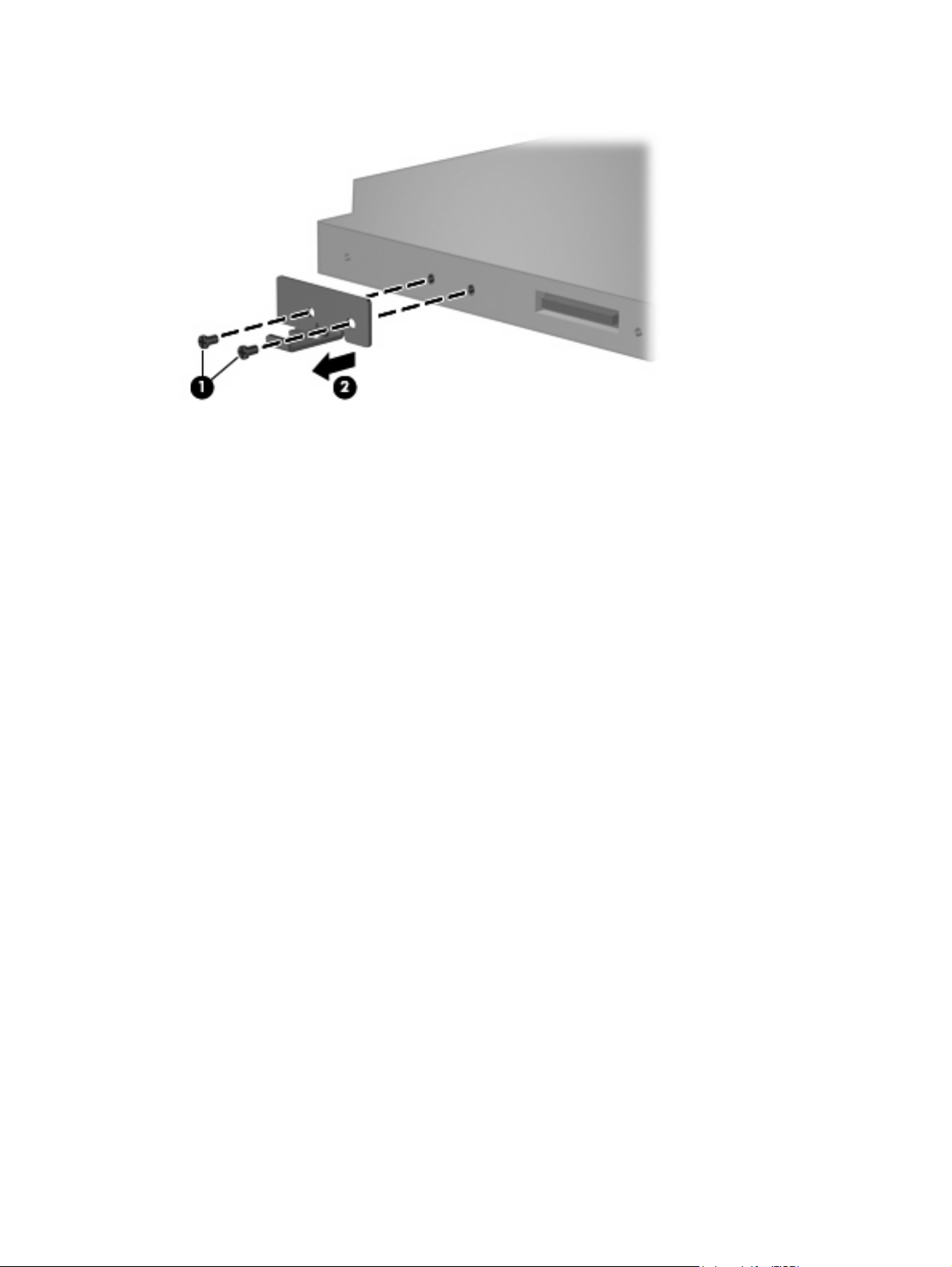
Remove the optical drive:
Position the computer with left side toward you.
1.
2. Remove the Phillips PM2.0×9.0 screw (1) that secures the optical drive to the computer.
3. Use a flat-bladed tool to push the metal tab (2) toward the left side of the computer. (The optical
drive partially removes from the optical drive bay.)
4. Remove the optical drive (3) from the computer.
If it is necessary to replace the optical drive bracket, remove the two Phillips PM2.0×3.0 screws
5.
(1) that secure the bracket to the optical drive.
Component replacement procedures 39
Page 48
6. Remove the optical drive bracket (2).
Reverse this procedure to reassemble and install the optical drive.
40 Chapter 4 Removal and replacement procedures
Page 49

Switch cover
Description Spare part number
For use only with computer models with wireless LAN capability (includes wireless button and wireless
light)
For use only with computer models without wireless LAN capability 438560-001
438561-001
Before removing the switch cover, follow these steps:
Shut down the computer. If you are unsure whether the computer is off or in Hibernation, turn the
1.
computer on, and then shut it down through the operating system.
Disconnect all external devices connected to the computer.
2.
Disconnect the power from the computer by first unplugging the power cord from the AC outlet and
3.
then unplugging the AC adapter from the computer.
Remove the battery (see
4.
Battery on page 31).
Remove the switch cover:
Turn the computer upside down, with the rear panel toward you.
1.
Remove the five Phillips PM2.0×9.0 screws that secure the switch cover to the computer.
2.
Partially open the computer.
3.
Component replacement procedures 41
Page 50

Use a flat-bladed tool to gently pry the tabs on the switch cover out of the slots on the computer.
4.
Turn the computer display-side up, with the front toward you.
5.
Open the computer as far as possible.
6.
Lift the rear edge of the switch cover and swing it forward.
7.
Remove the switch cover.
8.
Reverse this procedure to install the switch cover.
42 Chapter 4 Removal and replacement procedures
Page 51

Keyboard
For use in: Spare part number For use in: Spare part number
Brazil
The Czech Republic
The Netherlands and Europe
France
Greece
Hungary
Israel
Japan
Korea
Latin America
438531-201
438531-221
438531-021
438531-051
438531-151
438531-211
438531-BB1
438531-291
438531-AD1
438531-161
Poland
Russia
Saudi Arabia
Slovakia
Slovenia
South Africa
Thailand
Turkey
The United Kingdom
The United States
438531-241
438531-251
438531-171
438531-231
438531-BA1
438531-AR1
438531-281
438531-141
438531-031
438531-001
Before removing the keyboard, follow these steps:
Shut down the computer. If you are unsure whether the computer is off or in Hibernation, turn the
1.
computer on, and then shut it down through the operating system.
Disconnect all external devices connected to the computer.
2.
Disconnect the power from the computer by first unplugging the power cord from the AC outlet and
3.
then unplugging the AC adapter from the computer.
Remove the battery (see
4.
Remove the memory/WLAN module compartment cover (see
5.
Battery on page 31).
Memory module on page 35).
Remove the keyboard:
Position the computer with the front toward you.
1.
Remove the two Phillips PM2.0×9.0 screws that secure the keyboard to the computer.
2.
Turn the computer display-side up, with the front toward you.
3.
Component replacement procedures 43
Page 52

Open the computer as far as possible.
4.
Lift the rear edge of the keyboard and swing it toward you until it rests on the palm rest.
5.
6. Release the zero insertion force (ZIF) connector (1) to which the keyboard cable is attached, and
disconnect the keyboard cable (2).
Remove the keyboard.
7.
Reverse this procedure to install the keyboard.
44 Chapter 4 Removal and replacement procedures
Page 53

Display assembly
Description Spare part number
14.1-inch, WXGA BrightView display assembly for use only with computer models with wireless LAN
capability (includes wireless antenna transceivers and cables)
14.1-inch, WXGA BrightView display assembly for use only with computer models without wireless
LAN capability
448328-001
448327-001
Before removing the display assembly, follow these steps:
Shut down the computer. If you are unsure whether the computer is off or in Hibernation, turn the
1.
computer on, and then shut it down through the operating system.
Disconnect all external devices connected to the computer.
2.
Disconnect the power from the computer by first unplugging the power cord from the AC outlet and
3.
then unplugging the AC adapter from the computer.
Remove the battery (see
4.
Remove the memory/WLAN module compartment cover (see
5.
disconnect the wireless antenna cables from the WLAN module (see
Remove the following components:
6.
Switch cover (see
a.
Keyboard (see
b.
Battery on page 31).
Memory module on page 35) and
WLAN module on page 37).
Switch cover on page 41)
Keyboard on page 43)
Remove the display assembly:
Close the computer and turn it upside down, with the rear panel toward you.
1.
Remove the two Phillips PM2.0×7.0 screws that secure the display assembly to the computer.
2.
Turn the computer display-side up, with the front toward you.
3.
Open the computer until the display assembly is in an upright position.
4.
Component replacement procedures 45
Page 54

5. Disconnect the display cable connector(1) from the system board and remove the display panel
cable (2) from the clips and routing channel built into the top cover.
6. Remove the wireless antenna cables (3) from the clips and routing channel built into the top cover.
7. Remove the two Phillips PM2.0×9.0 screws (4) that secure the display assembly to the computer.
Lift the display assembly straight up and remove it.
8.
46 Chapter 4 Removal and replacement procedures
Page 55
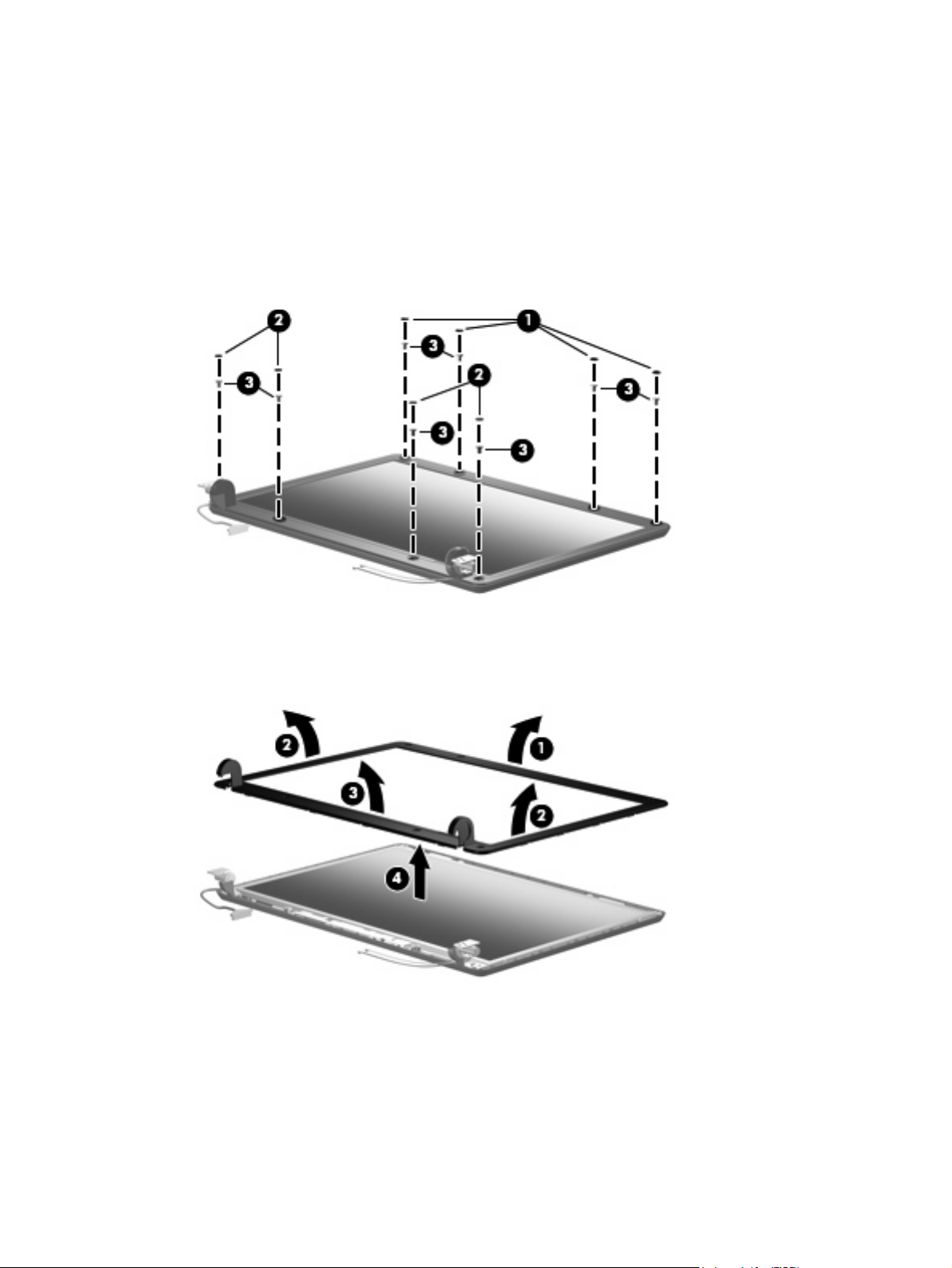
If it is necessary to replace the display bezel or any of the display assembly internal subcomponents,
9.
remove the following display bezel screw covers and screws:
(1) Four round rubber screw covers on the display bezel top edge. The display bezel screw covers
are available in the Display Screw Cover Kit, spare part number 438542-001. All screws used to
secure display assembly internal subcomponents are available in the Display Screw Kit, spare part
number 438543-001.
(2) Four flat rubber screw covers on the display bezel bottom edge.
(3) Eight Phillips PM2.5×6.0 screws.
10. Flex the inside edges of the top side (1), the left and right sides (2) of the display bezel, and the
bottom side (3) of the display bezel until the bezel disengages from the display assembly.
11. Remove the display bezel (4). The bezel is available using spare part number 438535-001.
12. If it is ne cess ary to re pla ce the display inverter, remove the Phillips PM2.5×6.0 screw (1) that secures
the inverter to the display enclosure.
13. Disconnect the display panel cable (2) and the backlight cable (3) from the inverter.
Component replacement procedures 47
Page 56

14. Remove the display inverter (4). The inverter is available using spare part number 448332-001.
15. If it is necessary to replace the display panel, remove the four Phillips PM2.5×6.0 screws (1) that
secure the panel to the display enclosure.
16. Remove the display panel (2). The panel is available using spare part number 448333-001.
If it is necessary to replace either of the display hinges, remove the four Phillips PM2.0×3.0
17.
screws (1) that secure each hinge to the display panel.
48 Chapter 4 Removal and replacement procedures
Page 57

18. Remove the display hinges (2). The hinges are available in the Display Bracket/Hinge Kit, spare
part number 448335-001.
19. If it is necessary to replace the wireless antenna transceivers (1) and cables (2), remove the
transceivers and cables from the display enclosure. The wireless antenna transceivers and cables are
available in the Wireless Antenna Kit, spare part number 438516-001.
NOTE: The wireless antenna transceivers are attached to the display enclosure by a thin layer of
adhesive. It may be necessary to use a flat-bladed tool to pry the transceivers away from the display
enclosure.
Reverse this procedure to reassemble and install the display assembly.
Component replacement procedures 49
Page 58

Base enclosure
Description Spare part number
Base enclosure 438517-001
Before removing the base enclosure, follow these steps:
Shut down the computer. If you are unsure whether the computer is off or in Hibernation, turn the
1.
computer on, and then shut it down through the operating system.
Disconnect all external devices connected to the computer.
2.
Disconnect the power from the computer by first unplugging the power cord from the AC outlet and
3.
then unplugging the AC adapter from the computer.
Remove the battery (see
4.
Remove the following components:
5.
Hard drive (see
a.
Memory/WLAN module compartment cover (see
b.
Optical drive (see
c.
Switch cover (see
d.
Keyboard (see
e.
Display assembly (see
f.
Battery on page 31).
Hard drive on page 32)
Memory module on page 35)
Optical drive on page 39)
Switch cover on page 41)
Keyboard on page 43)
Display assembly on page 45)
Remove the base enclosure:
1. Release the ZIF connector (1) to which the TouchPad cable is attached, and disconnect the TouchPad
cable (2) from the system board.
Turn the computer upside down, with the front toward you.
2.
50 Chapter 4 Removal and replacement procedures
Page 59
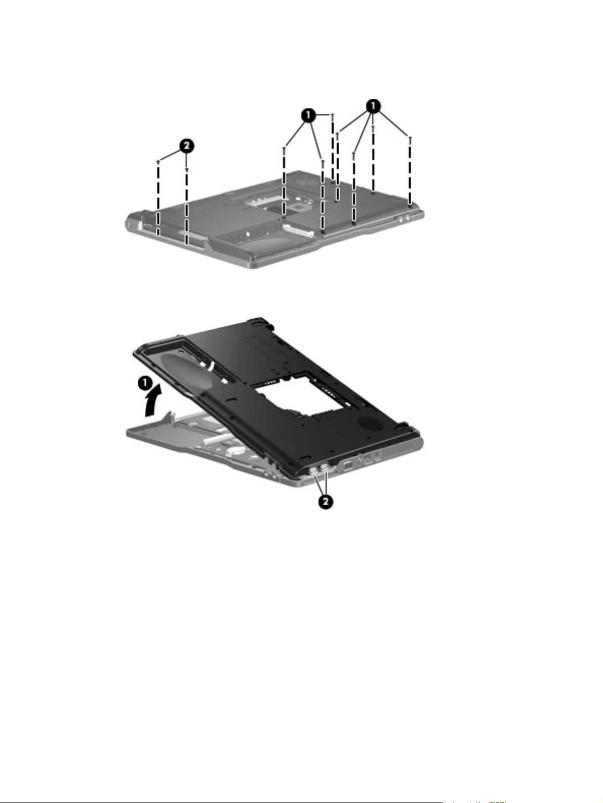
3. Remove the seven Phillips PM2.0×9.0 screws (1) and the two Phillips PM2.0×3.0 screws (2) that
secure the base enclosure to the computer.
4. Lift the left side of the base enclosure (1) until the USB connectors (2) disengage from their openings
in the base enclosure.
Remove the base enclosure.
5.
Reverse this procedure to install the base enclosure.
Component replacement procedures 51
Page 60

RTC battery
NOTE: Removing the RTC battery and leaving it uninstalled for 5 or more minutes causes all passwords
and CMOS settings to be cleared.
Description Spare part number
RTC battery 438556-001
Before removing the RTC battery, follow these steps:
Shut down the computer. If you are unsure whether the computer is off or in Hibernation, turn the
1.
computer on, and then shut it down through the operating system.
Disconnect all external devices connected to the computer.
2.
Disconnect the power from the computer by first unplugging the power cord from the AC outlet and
3.
then unplugging the AC adapter from the computer.
Remove the battery (see
4.
Remove the following components:
5.
Hard drive (see
a.
Memory/WLAN module compartment cover (see
b.
Optical drive (see
c.
Switch cover (see
d.
Keyboard (see
e.
Display assembly (see
f.
Base enclosure (see
g.
Battery on page 31).
Hard drive on page 32)
Memory module on page 35)
Optical drive on page 39)
Switch cover on page 41)
Keyboard on page 43)
Display assembly on page 45)
Base enclosure on page 50)
Remove the RTC battery:
Use a non-conductive, flat-bladed tool to pry the RTC battery out of the socket.
▲
52 Chapter 4 Removal and replacement procedures
Page 61

Reverse this procedure to install the RTC battery. Be sure the RTC battery is installed with the “+” sign
facing up.
Fan assembly
Description Spare part number
Fan assembly 438528-001
Before removing the fan assembly, follow these steps:
Shut down the computer. If you are unsure whether the computer is off or in Hibernation, turn the
1.
computer on, and then shut it down through the operating system.
Disconnect all external devices connected to the computer.
2.
Disconnect the power from the computer by first unplugging the power cord from the AC outlet and
3.
then unplugging the AC adapter from the computer.
Remove the battery (see
4.
Remove the following components:
5.
Hard drive (see
a.
Memory/WLAN module compartment cover (see
b.
Optical drive (see
c.
Switch cover (see
d.
Keyboard (see
e.
Display assembly (see
f.
Base enclosure (see
g.
Battery on page 31).
Hard drive on page 32)
Memory module on page 35)
Optical drive on page 39)
Switch cover on page 41)
Keyboard on page 43)
Display assembly on page 45)
Base enclosure on page 50)
Remove the fan assembly:
1. Disconnect the fan cable (1) from the system board.
2. Remove the Phillips PM2.0×9.0 screw (2) that secures the fan assembly to the top cover.
Component replacement procedures 53
Page 62

3. Remove the fan assembly (3).
Reverse this procedure to install the fan assembly.
NOTE: To properly ventilate the computer, allow at least a 7.6-cm (3-inch) clearance on the left and
right sides of the computer.
The computer uses an electric fan for ventilation. The fan is controlled by a temperature sensor and is
designed to be turned on automatically when high temperature conditions exist. These conditions are
affected by high external temperatures, system power consumption, power management/battery
conservation configurations, battery fast charging, and software applications. Exhaust air is displaced
through the ventilation grill located on the left side of the computer.
54 Chapter 4 Removal and replacement procedures
Page 63

Heat sink
Description Spare part number
Heat sink (includes thermal material) 448336-001
Before removing the heat sink, follow these steps:
1.
2.
3.
Shut down the computer. If you are unsure whether the computer is off or in Hibernation, turn the
computer on, and then shut it down through the operating system.
Disconnect all external devices connected to the computer.
Disconnect the power from the computer by first unplugging the power cord from the AC outlet and
then unplugging the AC adapter from the computer.
Remove the battery (see
4.
Remove the following components:
5.
Hard drive (see
a.
Memory/WLAN module compartment cover (see
b.
Optical drive (see
c.
Switch cover (see
d.
Keyboard (see
e.
Display assembly (see
f.
Base enclosure (see
g.
Fan assembly (see
h.
Battery on page 31).
Hard drive on page 32)
Memory module on page 35)
Optical drive on page 39)
Switch cover on page 41)
Keyboard on page 43)
Display assembly on page 45)
Base enclosure on page 50)
Fan assembly on page 53)
Remove the heat sink:
1. Remove the four Phillips PM2.5×6.0 screws (1) that secure the heat sink to the system board.
2. Release the heat sink (2) by sliding it to the left until the right side of the heat sink clears the top
cover.
NOTE: Due to the adhesive quality of the thermal material located between the heat sink and
processor, it may be necessary to move the heat sink from side to side to detach the heat sink from
the processor.
Component replacement procedures 55
Page 64
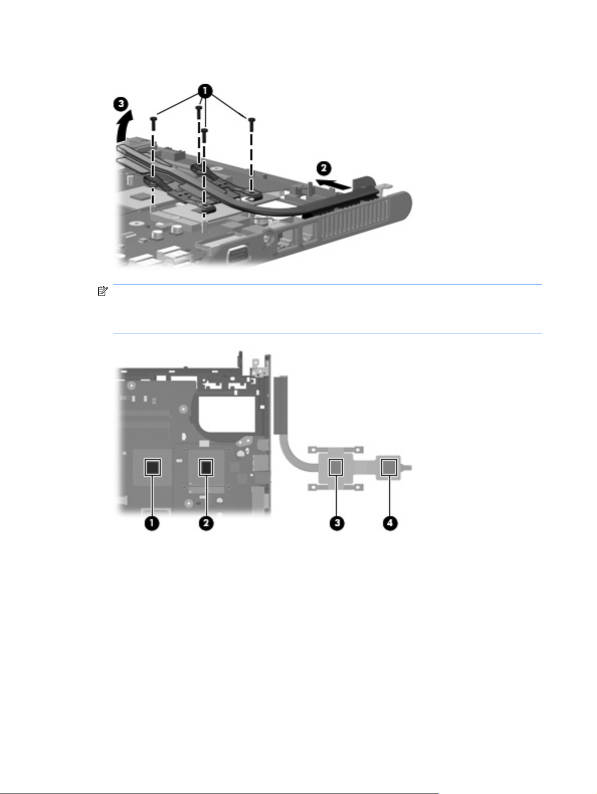
3. Lift the left side of the heat sink (3) and remove it.
NOTE: The thermal material should be thoroughly cleaned from the surfaces of the video
processor (1), the processor (2), and the heat sink (3) and (4) each time the heat sink is removed.
Reapply the thermal material when the heat sink is replaced. Thermal material is included with all
heat sink, processor, and system board spare part kits.
Reverse this procedure to install the heat sink.
56 Chapter 4 Removal and replacement procedures
Page 65

Processor
NOTE: All processor spare part kits include thermal material.
Description Spare part number
Intel Core Solo T1400 1.83-GHz processor 448326-001
Intel Core Solo T1300 1.66-GHz processor 448325-001
Intel Core Duo T2300E 1.66-GHz processor 448324-001
Intel Core Duo T2300 1.66-GHz processor 448323-001
Intel Celeron M 420 1.60-GHz processor 448322-001
Intel Celeron M 410 1.46-GHz processor 448321-001
Before removing the processor, follow these steps:
1.
2.
3.
Shut down the computer. If you are unsure whether the computer is off or in Hibernation, turn the
computer on, and then shut it down through the operating system.
Disconnect all external devices connected to the computer.
Disconnect the power from the computer by first unplugging the power cord from the AC outlet and
then unplugging the AC adapter from the computer.
Remove the battery (see
4.
Remove the following components:
5.
Hard drive (see
a.
Memory/WLAN module compartment cover (see
b.
Optical drive (see
c.
Switch cover (see
d.
Keyboard (see
e.
Display assembly (see
f.
Base enclosure (see
g.
Fan assembly (see
h.
Heat sink (see
i.
Battery on page 31).
Hard drive on page 32)
Memory module on page 35)
Optical drive on page 39)
Switch cover on page 41)
Keyboard on page 43)
Display assembly on page 45)
Base enclosure on page 50)
Fan assembly on page 53)
Heat sink on page 55)
Remove the processor:
1. Use a flat-bladed screwdriver to turn the processor locking screw (1) one-half turn counterclockwise
until you hear a click.
Component replacement procedures 57
Page 66
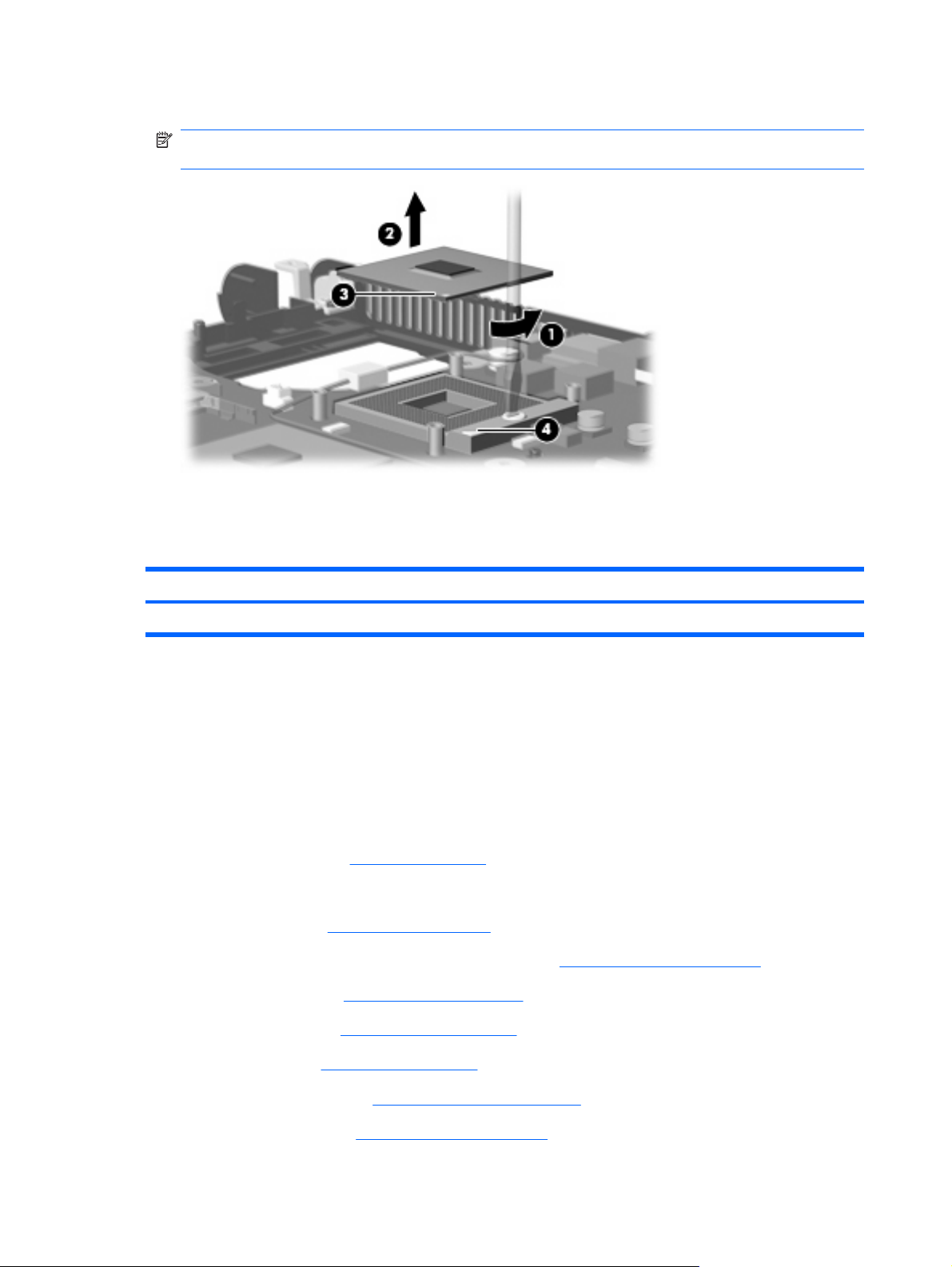
2. Lift the processor (2) straight up and remove it.
Reverse this procedure to install the processor.
Speaker
NOTE: The gold triangle (3) on the processor should be aligned with the triangle (4) embossed
on the processor socket when you install the processor.
Description Spare part number
Speaker 438559-001
Before removing the speaker, follow these steps:
Shut down the computer. If you are unsure whether the computer is off or in Hibernation, turn the
1.
computer on, and then shut it down through the operating system.
Disconnect all external devices connected to the computer.
2.
Disconnect the power from the computer by first unplugging the power cord from the AC outlet and
3.
then unplugging the AC adapter from the computer.
Remove the battery (see
4.
Remove the following components:
5.
Hard drive (see
a.
Memory/WLAN module compartment cover (see
b.
Optical drive (see
c.
Switch cover (see
d.
Battery on page 31).
Hard drive on page 32)
Memory module on page 35)
Optical drive on page 39)
Switch cover on page 41)
Keyboard (see
e.
Display assembly (see
f.
Base enclosure (see
g.
Keyboard on page 43)
Display assembly on page 45)
Base enclosure on page 50)
58 Chapter 4 Removal and replacement procedures
Page 67
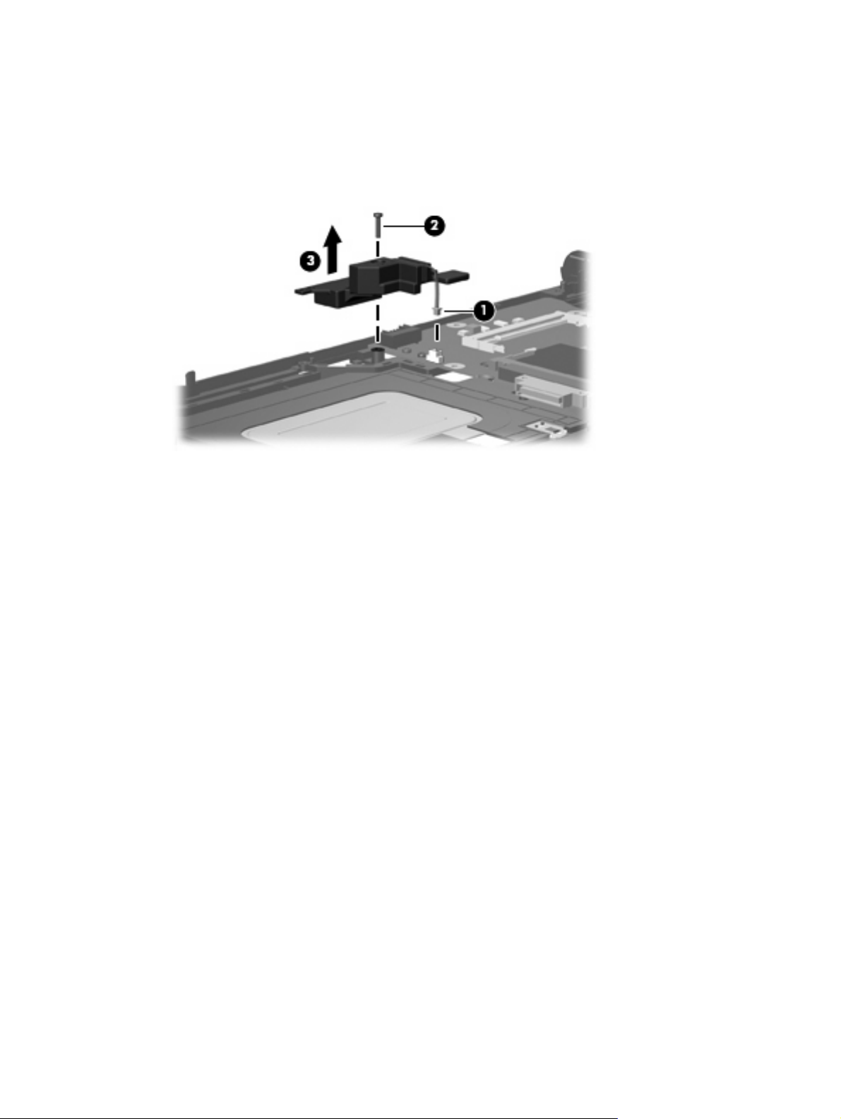
Remove the speaker:
1. Disconnect the speaker cable (1) from the system board.
2. Remove the Phillips PM2.0×9.0 screw (2) that secures the speaker to the top cover.
3. Remove the speaker (3).
Reverse this procedure to install the speaker.
Component replacement procedures 59
Page 68

System board
Description Spare part number
For use only with computer models with Intel Core processors and WLAN capability 448339-001
For use only with computer models with Intel Celeron M processors and WLAN capability 448337-001
For use only with computer models without WLAN capability 448338-001
When replacing the system board, be sure that the following components are removed from the defective
system board and installed on the replacement system board:
Memory module (see
●
WLAN module (see
●
RTC battery (see
●
Processor (see
●
PC Card assembly (see
●
Memory module on page 35)
WLAN module on page 37)
RTC battery on page 52)
Processor on page 57)
PC Card assembly on page 62)
Before removing the system board, follow these steps:
Shut down the computer. If you are unsure whether the computer is off or in Hibernation, turn the
1.
computer on, and then shut it down through the operating system.
Disconnect all external devices connected to the computer.
2.
Disconnect the power from the computer by first unplugging the power cord from the AC outlet and
3.
then unplugging the AC adapter from the computer.
Remove the battery (see
4.
Remove the following components:
5.
Hard drive (see
a.
Memory/WLAN module compartment cover (see
b.
Battery on page 31).
Hard drive on page 32)
Memory module on page 35)
Optical drive (see
c.
Switch cover (see
d.
Keyboard (see
e.
Display assembly (see
f.
Base enclosure (see
g.
Fan assembly (see
h.
Heat sink (see
i.
Optical drive on page 39)
Switch cover on page 41)
Keyboard on page 43)
Display assembly on page 45)
Base enclosure on page 50)
Fan assembly on page 53)
Heat sink on page 55)
60 Chapter 4 Removal and replacement procedures
Page 69

Remove the system board:
Remove the Phillips PM2.0×3.0 screw that secures the system board to the top cover .
1.
2. Use the optical drive connector (1) to lift the left side of the system board (2) until it rests at an angle.
3. Flex the right side of the top cover (3) until the external monitor connector clears the opening in the
top cover.
4. Slide the system board (4) away from the top cover at an angle until it clears the top cover
Reverse this procedures to install the system board.
Component replacement procedures 61
Page 70

PC Card assembly
Description Spare part number
PC Card assembly 438551-001
PC Card slot bezel 438527-001
Before removing the PC Card assembly, follow these steps:
Shut down the computer. If you are unsure whether the computer is off or in Hibernation, turn the
1.
computer on, and then shut it down through the operating system.
Disconnect all external devices connected to the computer.
2.
Disconnect the power from the computer by first unplugging the power cord from the AC outlet and
3.
then unplugging the AC adapter from the computer.
Remove the battery (see
4.
Remove the following components:
5.
Hard drive (see
a.
Memory/WLAN module compartment cover (see
b.
Optical drive (see
c.
Switch cover (see
d.
Keyboard (see
e.
Display assembly (see
f.
Base enclosure (see
g.
Fan assembly (see
h.
Heat sink (see
i.
System board (see
j.
Battery on page 31).
Hard drive on page 32)
Memory module on page 35)
Optical drive on page 39)
Switch cover on page 41)
Keyboard on page 43)
Display assembly on page 45)
Base enclosure on page 50)
Fan assembly on page 53)
Heat sink on page 55)
System board on page 60)
Remove the PC Card assembly:
Position the system board with the PC Card eject button toward you.
1.
62 Chapter 4 Removal and replacement procedures
Page 71

2. Remove the two Phillips PM2.0×7.0 screws (1) and two Phillips PM2.0×4.0 screws (2) that secure
the PC Card assembly to the system board.
Turn the system board top-side up, with the PC Card eject button toward you.
3.
4. Disengage the slots on the PC Card assembly from the tabs (1) on the PC Card connector.
5. Remove the PC Card assembly (2) from the system board.
Reverse this procedure to install the PC Card assembly.
Component replacement procedures 63
Page 72

TouchPad cable
Description Spare part number
TouchPad cable 438562-001
Before removing the TouchPad cable, follow these steps:
Shut down the computer. If you are unsure whether the computer is off or in Hibernation, turn the
1.
computer on, and then shut it down through the operating system.
Disconnect all external devices connected to the computer.
2.
Disconnect the power from the computer by first unplugging the power cord from the AC outlet and
3.
then unplugging the AC adapter from the computer.
Remove the battery (see
4.
Remove the following components:
5.
Hard drive (see
a.
Memory/WLAN module compartment cover (see
b.
Optical drive (see
c.
Switch cover (see
d.
Keyboard (see
e.
Display assembly (see
f.
Base enclosure (see
g.
Fan assembly (see
h.
Heat sink (see
i.
System board (see
j.
Battery on page 31).
Hard drive on page 32)
Optical drive on page 39)
Switch cover on page 41)
Keyboard on page 43)
Display assembly on page 45)
Base enclosure on page 50)
Fan assembly on page 53)
Heat sink on page 55)
System board on page 60)
Remove the TouchPad cable:
Position the top cover with the front toward you.
1.
Memory module on page 35)
64 Chapter 4 Removal and replacement procedures
Page 73

2. Release the ZIF connector (1) to which the TouchPad cable is connected, and disconnect the
TouchPad cable (2) from the TouchPad board.
Reverse this procedure to install the TouchPad cable.
Component replacement procedures 65
Page 74

66 Chapter 4 Removal and replacement procedures
Page 75

5
Computer Setup
Starting Computer Setup
Computer Setup is a preinstalled, ROM-based utility that can be used even when the operating system is
not working or will not load.
NOTE: Some of the Computer Setup menu items listed in this guide may not be supported by your
computer.
NOTE: Pointing devices are not supported in Computer Setup. You must use the keyboard to navigate
and make selections.
NOTE: An external keyboard connected by USB can be used with Computer Setup only if USB legacy
support is enabled.
To start Computer Setup:
Turn on or restart the computer.
1.
Before Windows® opens and while the "F10 = ROM Based Setup" message is displayed in the
2.
lower-left corner of the screen, press f10.
Starting Computer Setup 67
Page 76

Using Computer Setup
Navigating and selecting in Computer Setup
The information and settings in Computer Setup are accessed from the File, Security, Diagnostics, and
System Configuration menus.
Open Computer Setup by turning on or restarting the computer, and then pressing f10 while the
1.
"F10 = ROM Based Setup" message is displayed in the lower-left corner of the screen.
Because Computer Setup is not Windows-based, it does not support the TouchPad. Navigation and
selection are by keystroke:
To choose a menu or a menu item, use the arrow keys.
●
To select an item, press enter.
●
To close open dialog boxes and return to the main Computer Setup screen, press esc.
●
To view navigation information, press f1.
●
To change the language, press f2.
●
2. Select the File, Security, Diagnostics, or System Configuration menu.
To exit Computer Setup, choose one of the following methods:
3.
●
To exit Computer Setup without saving your preferences, use the arrow keys to select File >
Ignore Changes and Exit. Then follow the instructions on the screen.
●
To save your preferences and exit Computer Setup, use the arrow keys to select File > Save
Changes and Exit. Then follow the instructions on the screen.
Your preferences go into effect when the computer restarts.
Restoring factory settings in Computer Setup
To return all settings in Computer Setup to the values that were set at the factory, follow these steps:
Open Computer Setup by turning on or restarting the computer, and then pressing f10 while the
1.
"F10 = ROM Based Setup" message is displayed in the lower-left corner of the screen.
Use the arrow keys to select File > Restore defaults, and then press enter.
2.
When the confirmation dialog box opens, press f10.
3.
4. To save your preferences and exit Computer Setup, use the arrow keys to select File > Save
Changes and Exit. Then follow the instructions on the screen.
Your preferences go into effect when the computer restarts.
NOTE: Your password settings and security settings are not changed when you restore the factory
settings.
68 Chapter 5 Computer Setup
Page 77

Computer Setup menus
The menu tables in this section provide an overview of Computer Setup options.
NOTE: Some of the Computer Setup menu items listed in this chapter may not be supported by your
computer.
File menu
Select To do this
System information
Restore defaults Replace the configuration settings in Computer Setup with the original factory settings.
Ignore changes and exit Cancel any changes entered during the current session. Then exit and restart the computer.
Save changes and exit Save any changes entered during the current session. Then exit and restart the computer. Your
View identification information for the computer and the batteries in the system.
●
View specification information for the processor, cache and memory size, system ROM,
●
video revision, and keyboard controller version.
(Password settings and security settings are not changed when you restore the factory settings.)
changes go into effect when the computer restarts.
Computer Setup menus 69
Page 78

Security menu
Select To do this
Setup password Enter, change, or delete a setup password.
Power-On password Enter, change, or delete a power-on password.
Password options
DriveLock passwords
Smart Card security Enable/disable support for smart card and Java™ Card power-on authentication.
TPM Embedded Security Enable/disable support for Trusted Platform Module (TPM) Embedded Security, which protects
System IDs Enter user-defined computer asset tracking number and ownership tag.
Disk Sanitizer Run Disk Sanitizer to destroy all existing data on the primary hard drive. The following options
Enable/disable stringent security.
●
Enable/disable password requirement on computer restart.
●
Enable/disable DriveLock on any computer hard drive and on optional MultiBay hard
●
drives.
● Change a DriveLock user password or master password.
NOTE: DriveLock settings are accessible only when you enter Computer Setup by turning on
(not restarting) the computer.
NOTE: Power-on authentication for smart cards is supported only on computers with optional
smart card readers.
NOTE: You must have an administrator password to change this setting.
the computer from unauthorized access to owner functions available in Embedded Security for
ProtectTools. For more information, refer to the ProtectTools software Help.
NOTE: You must have a setup password to change this setting.
are available:
Fast: Runs the Disk Sanitizer erase cycle once.
●
Diagnostics menu
Select To do this
Hard Drive Self-Test options Run a comprehensive self-test on any hard drive in the system or on any optional MultiBay hard
Memory Check Run a comprehensive check on system memory.
Startup Check (select models
only)
Optimum: Runs the Disk Sanitizer erase cycle 3 times.
●
Custom: Allows you to select the desired number of Disk Sanitizer erase cycles from a list.
●
CAUTION: If you run Disk Sanitizer, the data on the primary hard drive is destroyed
permanently.
drive.
Verify the system components needed for starting the computer.
70 Chapter 5 Computer Setup
Page 79

System Configuration menu
NOTE: Some of the listed System Configuration options may not be supported by your computer.
Select To do this
Language (or press f2) Change the Computer Setup language.
Boot options
Device configurations
Set f9, f10, and f12 delay when starting up.
●
Enable/disable CD-ROM boot.
●
Enable/disable floppy boot.
●
Enable/disable internal network adapter boot and set the boot mode (PXE or RPL).
●
Enable/disable MultiBoot, which sets a boot order that can include most boot devices in
●
the system.
Set the Express Boot Popup delay in seconds.
●
Set the boot order.
●
Swap the functions of the fn key and left ctrl key.
●
Enable/disable multiple standard pointing devices at startup. (To set the computer to
●
support only a single, usually nonstandard, pointing device at startup, select Disable.)
Enable/disable USB legacy support. When enabled, USB legacy support allows the
●
following:
Use of a USB keyboard, mouse, and hub in Computer Setup even when a Windows
◦
operating system is not running.
Startup from bootable USB devices, including a hard drive, diskette drive, or optical
◦
drive connected by a USB port to the computer or to an optional docking device
(select models only).
● Select a parallel port mode: EPP (Enhanced Parallel Port), standard, bidirectional, or ECP
(Enhanced Capabilities Port).
Built-In Device Options
Enable/disable BIOS DMA data transfers.
●
Enable/disable fan always on while connected to an AC outlet.
●
Enable/disable Intel® Data Execution Prevention or AMD® PSAE Execution Disable.
●
When enabled, the processor can disable some virus code execution, which helps to
improve computer security.
Enable/disable LAN Power Save. When enabled, saves power by turning off the LAN
●
when not in use.
Enable/disable SATA Native Mode.
●
Enable/disable Dual Core CPU.
●
Enable/disable Secondary Battery Fast Charge.
●
Choose Bit-shift or LBA assisted HDD Translation Mode.
●
Enable/disable Windows direct application launcher.
●
Enable/disable HP Lockout.
●
Enable/disable embedded WWAN Device Radio.
●
Enable/disable embedded WLAN Device Radio.
●
Computer Setup menus 71
Page 80

Select To do this
● Enable/disable embedded Bluetooth® Device Radio.
Enable/disable LAN/WLAN Switching. When enabled, switches to a WLAN when a
●
LAN is either unavailable or disconnected.
Enable/disable Wake on LAN from Off.
●
Enable/disable the ambient light sensor.
●
Port Options
Enable/disable the serial port.
●
Enable/disable the parallel port.
●
Enable/disable the flash media reader.
●
Enable/disable the USB port.
●
CAUTION: Disabling the USB port also disables MultiBay devices and ExpressCard
devices on the advanced port replicator.
Enable/disable the 1394 port.
●
Enable/disable the cardbus slot.
●
Enable/disable the ExpressCard slot.
●
Enable/disable the infrared port.
●
Enable/disable the optical disk drive.
●
Enable/disable the network controller.
●
72 Chapter 5 Computer Setup
Page 81

6
Specifications
Computer specifications
Metric U.S.
Dimensions
Height (front to back)
Width 33.39 cm 13.19 in
Depth 24.68 cm 9.75 in
Weight (with optical drive, hard drive, and battery)
Input power
Operating voltage
Operating current 3.5 A
Temperature
Operating (not writing to optical disc)
Operating (writing to optical disc) 5°C to 35°C 41°F to 95°F
Nonoperating -20°C to 60°C -4°F to 140°F
Relative humidity
Operating
Nonoperating 5% to 95%
Maximum altitude (unpressurized)
Operating (14.7 to 10.1 psia)
3.01 to 3.41 cm 1.18 to 1.34 in
2.48 kg 5.47 lbs
18.5 V dc @ 3.5 A – 65 W
0°C to 35°C 32°F to 95°F
10% to 90%
-15 m to 3,048 m -50 ft to 10,000 ft
Nonoperating (14.7 to 4.4 psia) -15 m to 12,192 m -50 ft to 40,000 ft
Shock
Operating
Nonoperating 200 g, 2 ms, half-sine
Random vibration
Operating
125 g, 2 ms, half-sine
0.75 g zero-to-peak, 10 Hz to 500 Hz, 0.25 oct/min sweep rate
Computer specifications 73
Page 82

Metric U.S.
Nonoperating 1.50 g zero-to-peak, 10 Hz to 500 Hz, 0.5 oct/min sweep rate
NOTE: Applicable product safety standards specify thermal limits for plastic surfaces. The computer operates well within this
range of temperatures.
14.1-inch, WXGA display specifications
Metric U.S.
Dimensions
Height
Width 28.6 cm 11.2 in
Diagonal 35.7 cm 14.1 in
Number of colors
Contrast ratio
Brightness
Pixel resolution
Pitch
Format 1024 × 768
Configuration RGB stripe
Backlight
Refresh rate
PPI
Viewing angle
21.4 cm 8.4 in
Up to 16.8 million
300:1 (typical)
200 nits (typical)
0.237 × 0.237 mm
CCFL
60 Hz
107
+/-45° horizontal, +/-25° vertical (typical)
74 Chapter 6 Specifications
Page 83

Hard drive specifications
120-GB* 80-GB*
Dimensions
Height
Width 70 mm 70 mm
Weight 101 g 101 g
Interface type
Transfer rate
Synchronous (maximum)
Security ATA security ATA security
Seek times (typical read, including setting)
Single track
Average 13 ms 13 ms
Maximum 24 ms 24 ms
Logical blocks
Disc rotational speed
Operating temperature
*1 GB = 1 billion bytes when referring to hard drive storage capacity. Actual accessible capacity is less.
NOTE: Certain restrictions and exclusions apply. Consult technical support for details.
9.5 mm 9.5 mm
ATA-7 ATA-7
100 MB/sec 100 MB/sec
3 ms 3 ms
234,420,480 156,280,320
5400 rpm 5400 rpm
5°C to 55°C (41°F to 131°F)
Hard drive specifications 75
Page 84

Primary 4-cell, Li-ion battery specifications
Metric U.S.
Dimensions
Height
Width 26.80 cm 3.70 in
Depth 5.30 cm 5.28 in
Weight 0.34 kg 0.75 lb
Energy
Voltage
Amp-hour capacity 4.8 Ah
Watt-hour capacity 69 Wh
Temperature
Operating
Nonoperating 0°C to 60°C 32°F to 140°F
2.00 cm 0.79 in
14.4 V
5°C to 45°C 41°F to 113°F
76 Chapter 6 Specifications
Page 85

DVD±RW and CD-RW Super-Multi Double-Layer Combo Drive specifications
Applicable disc Read:
CD-DA, CD+(E)G, CD-MIDI, CD-TEXT, CDROM, CD-ROM XA, MIXED MODE CD, CD-I,
CD-I Bridge (Photo-CD, Video CD),
Multisession CD (Photo-CD, CD-EXTRA,
Portfolio, CD-R, CD-RW), CD-R, CD-RW, DVDROM (DVD-5, DVD-9, DVD-10, DVD-18), DVDR, DVD-RW, DVD+R, DVD+RW, DVD-RAM
Center hole diameter
Disc diameter
Standard disc
Mini disc 8 cm (3.15 in)
Disc thickness
Track pitch
Access time
Random < 175 ms < 230 ms
Full stroke < 285 ms < 335 ms
Audio output level
Cache buffer
1.5 cm (0.59 in)
12 cm (4.72 in)
1.2 mm (0.047 in)
0.74 μm
CD DVD
Audio-out, 0.7 Vrms
2 MB
Write:
CD-R and CD-RW
DVD+R, DVD+RW, DVD-R, DVD-RW, DVDRAM
Data transfer rate
24X CD-ROM
8X DVD 10,800 KB/sec
24X CD-R 3,600 KB/sec
16X CD-RW 2,400 KB/sec
8X DVD+R 10,800 KB/sec
4X DVD+RW 5,400 KB/sec
8X DVD-R 10,800 KB/sec
4X DVD-RW 5,400 KB/sec
2.4X DVD+R(9) 2,700 KB/sec
5X DVD-RAM 6,750 KB/sec
Transfer mode
Startup time
Stop time
3,600 KB/sec
Multiword DMA Mode
< 15 seconds
< 6 seconds
DVD±RW and CD-RW Super-Multi Double-Layer Combo Drive specifications 77
Page 86

DVD/CD-RW Combo Drive specifications
Applicable disc Read:
CD-DA, CD+(E)G, CD-MIDI, CD-TEXT, CDROM, CD-ROM XA, MIXED MODE CD, CD-I,
CD-I Bridge (Photo-CD, Video CD),
Multisession CD (Photo-CD, CD-EXTRA,
Portfolio, CD-R, CD-RW), CD-R, CD-RW, DVDROM (DVD-5, DVD-9, DVD-10, DVD-18), DVDR, DVD-RW, DVD+R, DVD+RW, DVD-RAM
Center hole diameter
Disc diameter
Standard disc
Mini disc 8 cm (3.15 in)
Disc thickness
Track pitch
Access time
Random < 110 ms < 130 ms
Full stroke < 210 ms < 225 ms
Audio output level
Cache buffer
1.5 cm (0.59 in)
12 cm (4.72 in)
1.2 mm (0.047 in)
0.74 μm
CD DVD
Line-out, 0.7 Vrms
2 MB
Write:
CD-R and CD-RW
Data transfer rate
24X CD-ROM
8X DVD 10,800 KB/sec
24X CD-R 3,600 KB/sec
24X CD-RW 3,600 KB/sec
Transfer mode
Startup time
Stop time
3,600 KB/sec
Multiword DMA mode 2
< 15 seconds
< 6 seconds
78 Chapter 6 Specifications
Page 87

System DMA specifications
Hardware DMA System function
DMA0 Not applicable
DMA1* Not applicable
DMA2* Not applicable
DMA3 Not applicable
DMA4 Direct memory access controller
DMA5* Available for PC Card
DMA6 Not assigned
DMA7 Not assigned
*PC Card controller can use DMA 1, 2, or 5.
System DMA specifications 79
Page 88

System interrupt specifications
Hardware IRQ System function
IRQ0 System timer
IRQ1 Standard 101-/102-Key or Microsoft Natural Keyboard
IRQ2 Cascaded
IRQ3 Intel 82801DB/DBM USB2 Enhanced Host Controller—24CD
IRQ4 COM1
IRQ5* Conexant AC—Link Audio Intel 82801DB/DBM SMBus Controller—24C3 Data
Fax Modem with SmartCP
IRQ6 Diskette drive
IRQ7* Parallel port
IRQ8 System CMOS/real-time clock
IRQ9* Microsoft ACPI-compliant system
IRQ10* Intel USB UHCI controller—24C2
Intel 82852/82855 GM/GME Graphic Controller
Realtek RTL8139 Family PCI fast Ethernet Controller
IRQ11 Intel USB EHCI controller—24CD
Intel USB UHCI controller—24C4
Intel USB UHCI controller—24C7
Intel Pro/Wireless 2200BG
TI OHCI 1394 host controller
TI PCI1410 CardBus controller
IRQ12 Synaptics PS/2 TouchPad
IRQ13 Numeric data processor
IRQ14 Primary IDE channel
IRQ15 Secondary IDE channel
*Default configuration; audio possible configurations are IRQ5, IRQ7, IRQ9, IRQ10, or none.
NOTE: PC Cards may assert IRQ3, IRQ4, IRQ5, IRQ7, IRQ9, IRQ10, IRQ11, or IRQ15. Either the infrared or the serial port
may assert IRQ3 or IRQ4.
80 Chapter 6 Specifications
Page 89

System I/O address specifications
I/O address (hex) System function (shipping configuration)
000 - 00F DMA controller no. 1
010 - 01F Unused
020 - 021 Interrupt controller no. 1
022 - 024 Opti chipset configuration registers
025 - 03F Unused
02E - 02F 87334 “Super I/O” configuration for CPU
040 - 05F Counter/timer registers
044 - 05F Unused
060 Keyboard controller
061 Port B
062 - 063 Unused
064 Keyboard controller
065 - 06F Unused
070 - 071 NMI enable/RTC
072 - 07F Unused
080 - 08F DMA page registers
090 - 091 Unused
092 Port A
093 - 09F Unused
0A0 - 0A1 Interrupt controller no. 2
I/O Address (hex) System Function (shipping configuration)
0A2 - 0BF Unused
0C0 - 0DF DMA controller no. 2
0E0 - 0EF Unused
0F0 - 0F1 Coprocessor busy clear/reset
0F2 - 0FF Unused
100 - 16F Unused
170 - 177 Secondary fixed disk controller
178 - 1EF Unused
1F0 - 1F7 Primary fixed disk controller
1F8 - 200 Unused
201 JoyStick (decoded in ESS1688)
202 - 21F Unused
System I/O address specifications 81
Page 90

I/O address (hex) System function (shipping configuration)
220 - 22F Entertainment audio
230 - 26D Unused
26E - 26 Unused
278 - 27F Unused
280 - 2AB Unused
2A0 - 2A7 Unused
2A8 - 2E7 Unused
2E8 - 2EF Reserved serial port
2F0 - 2F7 Unused
2F8 - 2FF Infrared port
300 - 31F Unused
320 - 36F Unused
370 - 377 Secondary diskette drive controller
378 - 37F Parallel port (LPT1/default)
380 - 387 Unused
388 - 38B FM synthesizer—OPL3
38C - 3AF Unused
3B0 - 3BB VGA
3BC - 3BF Reserved (parallel port/no EPP support)
3C0 - 3DF VGA
3E0 - 3E1 PC Card controller in CPU
3E2 - 3E3 Unused
3E8 - 3EF Internal modem
3F0 - 3F7 “A” diskette controller
3F8 - 3FF Serial port (COM1/default)
CF8 - CFB PCI configuration index register (PCIDIVO-1)
CFC - CFF PCI configuration data register (PCIDIVO-1)
82 Chapter 6 Specifications
Page 91

System memory map specifications
Size Memory address System function
640 KB 00000000-0009FFFF Base memory
128 KB 000A0000-000BFFFF Video memory
48 KB 000C0000-000CBFFF Video BIOS
160 KB 000C8000-000E7FFF Unused
64 KB 000E8000-000FFFFF System BIOS
15 MB 00100000-00FFFFFF Extended memory
58 MB 04800000-07FFFFFF Super extended memory
58 MB 04800000-07FFFFFF Unused
2 MB 08000000-080FFFFF Video memory (direct access)
4 GB 08200000-FFFEFFFF Unused
64 KB FFFF0000-FFFFFFFF System BIOS
System memory map specifications 83
Page 92

84 Chapter 6 Specifications
Page 93

7
Screw listing
This section provides specification and reference information for the screws and screw locks used in the
computer. All screws and screw locks listed in this section are available in the Screw Kit, spare part number
438558-001, and the Display Screw Kit, spare part number 438543-001.
85
Page 94
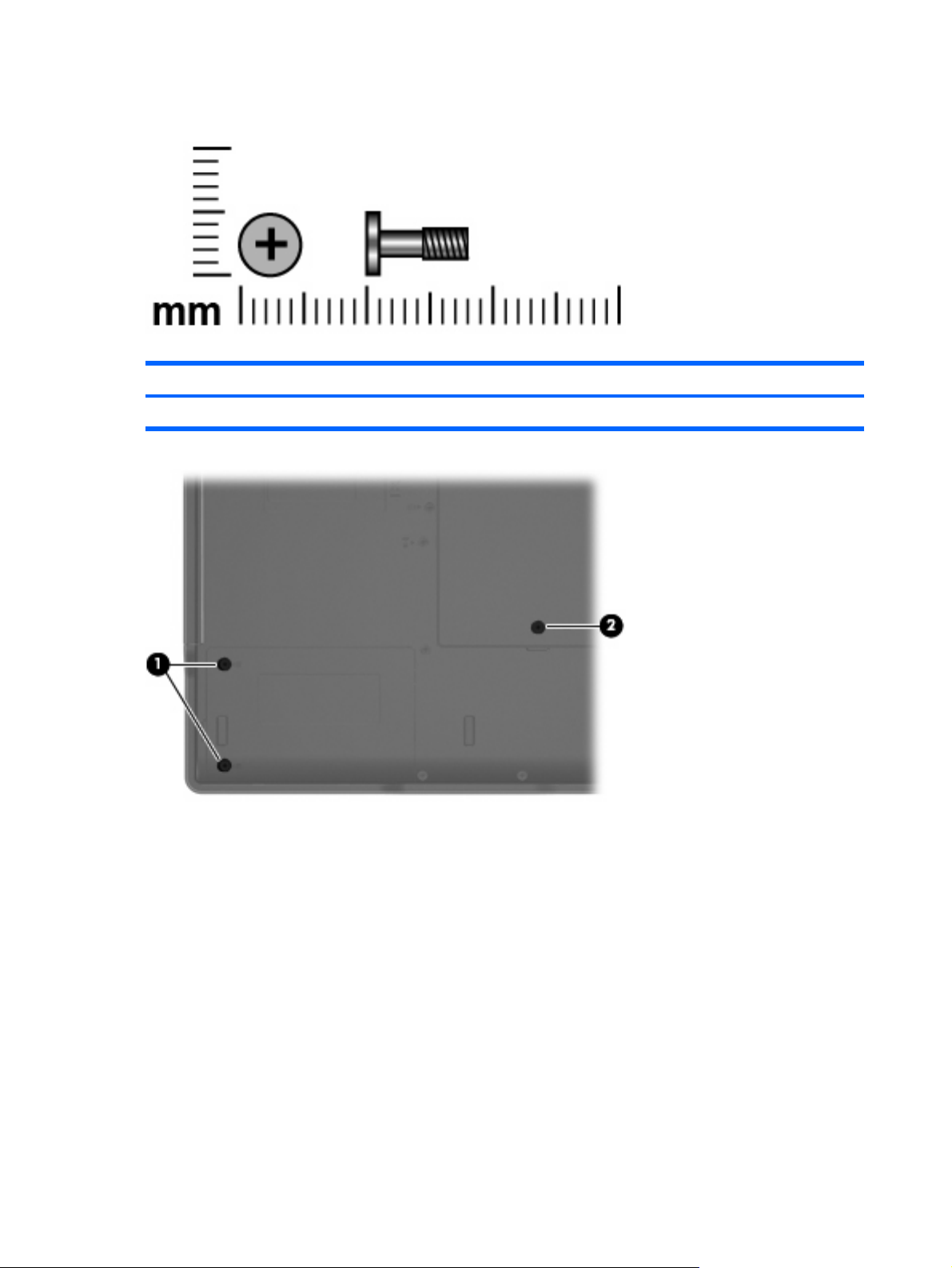
Phillips PM2.5×8.0 captive screw
Color Quantity Length Thread Head width
Black 3 8.0 mm 2.5 mm 5.0 mm
Where used:
(1) Two screws that secure the hard drive cover to the computer (screws are captured on the cover by C
clips)
(2) One screw that secures the memory/WLAN module compartment cover to the computer (screw is
captured on the cover by a C clip)
86 Chapter 7 Screw listing
Page 95
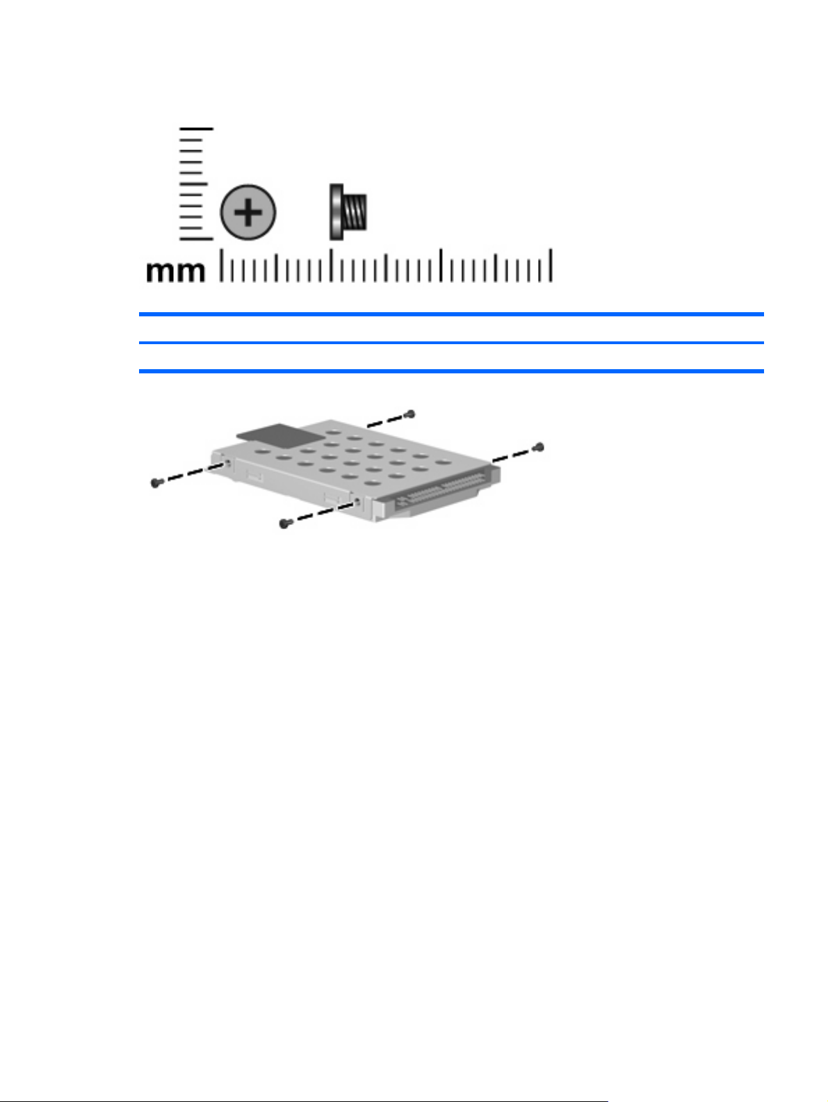
Phillips PM3.0×3.0 screw
Color Quantity Length Thread Head width
Silver 4 3.0 mm 3.0 mm 5.0 mm
Where used: 4 screws that secure the hard drive bracket to the hard drive
Phillips PM3.0×3.0 screw 87
Page 96

Phillips PM2.0×4.0 screw
Color Quantity Length Thread Head diameter
Black 2 4.0 mm 2.0 mm 4.5 mm
Where used: 2 screws that secure the WLAN module to the system board
88 Chapter 7 Screw listing
Page 97

Phillips PM2.0×9.0 screw
Color Quantity Length Thread Head width
Black 20 9.0 mm 2.0 mm 5.0 mm
Where used:
(1) One screw that secures the optical drive to the computer
(2) Five screws that secure the switch cover to the computer
(3) Two screws that secure the keyboard to the computer
Phillips PM2.0×9.0 screw 89
Page 98

Where used: 2 screws that secure the display assembly to the computer
Where used: One screw that secures the base enclosure to the computer
Where used: 7 screws that secure the base enclosure to the computer
90 Chapter 7 Screw listing
Page 99

Where used:
(1) One screw that secures the fan assembly to the computer
(2) One screw that secures the speaker to the computer
Phillips PM2.0×9.0 screw 91
Page 100
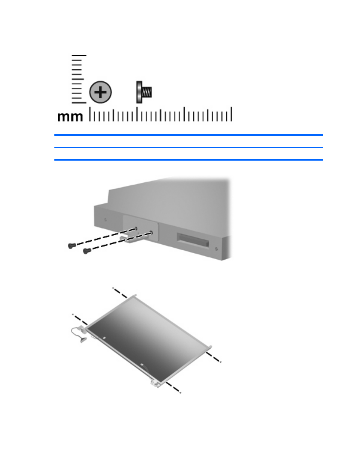
Phillips PM2.0×3.0 screw
Color Quantity Length Thread Head width
Silver 9 3.0 mm 2.0 mm 4.5 mm
Where used: 2 screws that secure the optical drive bracket to the optical drive
Where used: 4 screws that secure the display hinges to the display panel
92 Chapter 7 Screw listing
 Loading...