

Page 1

h
®
Tenor Carrier MultiPat
Switch (CMS)
i
d
u
8
c
0
0
0
5
-
0
-
0
0
d
r
o
P
P
/
N
4
u
G
t
e
-
1
5
Te nor and Quintum are registered trademarks. Tenor Carrier MultiPath Switch (CMS), PacketSaver,
Quintum Technologies, Inc., VoIP Made Easy, TASQ, SelectNet, and SelectNet Technology are trademarks of Quintum Technologies, Inc.
Page 2

Table of Contents
About this Guide
What’s included? . . . . . . . . . . . . . . . . . . . . . . . . . . . . . . . . . . . . . . . . . . . . . . . . . . . . . . . . . 1-2
Typographical Conventions . . . . . . . . . . . . . . . . . . . . . . . . . . . . . . . . . . . . . . . . . . . . . . . . . 1-3
Product Guide Conventions. . . . . . . . . . . . . . . . . . . . . . . . . . . . . . . . . . . . . . . . . . . . . 1-3
Finding Help. . . . . . . . . . . . . . . . . . . . . . . . . . . . . . . . . . . . . . . . . . . . . . . . . . . . . . . . . . . . . 1-4
Chapter 1: Overview
What is Tenor CMS? . . . . . . . . . . . . . . . . . . . . . . . . . . . . . . . . . . . . . . . . . . . . . . . . . . . . . . 1-2
Features. . . . . . . . . . . . . . . . . . . . . . . . . . . . . . . . . . . . . . . . . . . . . . . . . . . . . . . . . . . . . . . . 1-3
Unique Design . . . . . . . . . . . . . . . . . . . . . . . . . . . . . . . . . . . . . . . . . . . . . . . . . . . . . . . 1-3
State-of-the-Art Configuration and Network Management. . . . . . . . . . . . . . . . . . . . . . 1-3
SelectNet™ Technology Safety Net . . . . . . . . . . . . . . . . . . . . . . . . . . . . . . . . . . . . . . 1-4
Dynamic Call Routing . . . . . . . . . . . . . . . . . . . . . . . . . . . . . . . . . . . . . . . . . . . . . . . . . 1-4
Multiple Channels/Signaling Supported. . . . . . . . . . . . . . . . . . . . . . . . . . . . . . . . . . . . 1-4
Fractional T1/E1 Support. . . . . . . . . . . . . . . . . . . . . . . . . . . . . . . . . . . . . . . . . . . . . . . 1-4
PacketSaver™. . . . . . . . . . . . . . . . . . . . . . . . . . . . . . . . . . . . . . . . . . . . . . . . . . . . . . . 1-5
IVR/RADIUS support . . . . . . . . . . . . . . . . . . . . . . . . . . . . . . . . . . . . . . . . . . . . . . . . . 1-5
Easy Connect to Console . . . . . . . . . . . . . . . . . . . . . . . . . . . . . . . . . . . . . . . . . . . . . . 1-5
H.323 Gatekeeper Call Control Management . . . . . . . . . . . . . . . . . . . . . . . . . . . . . . . 1-5
Powerful System Monitoring . . . . . . . . . . . . . . . . . . . . . . . . . . . . . . . . . . . . . . . . . . . . 1-6
Capabilities . . . . . . . . . . . . . . . . . . . . . . . . . . . . . . . . . . . . . . . . . . . . . . . . . . . . . . . . . . . . . 1-7
Intra-trunk Routing - “Hairpinning” . . . . . . . . . . . . . . . . . . . . . . . . . . . . . . . . . . . . . . . . 1-8
Other Call Routing Options . . . . . . . . . . . . . . . . . . . . . . . . . . . . . . . . . . . . . . . . . . . . . 1-9
Virtual Tie Line. . . . . . . . . . . . . . . . . . . . . . . . . . . . . . . . . . . . . . . . . . . . . . . . . . . . . . . 1-9
Hop-off PBX Call . . . . . . . . . . . . . . . . . . . . . . . . . . . . . . . . . . . . . . . . . . . . . . . . . . . . . 1-10
SNMP Support. . . . . . . . . . . . . . . . . . . . . . . . . . . . . . . . . . . . . . . . . . . . . . . . . . . . . . . 1-10
Call Detail Recording. . . . . . . . . . . . . . . . . . . . . . . . . . . . . . . . . . . . . . . . . . . . . . . . . . 1-10
H.323 Gatekeeper Services. . . . . . . . . . . . . . . . . . . . . . . . . . . . . . . . . . . . . . . . . . . . . . . . . 1-11
Gatekeeper . . . . . . . . . . . . . . . . . . . . . . . . . . . . . . . . . . . . . . . . . . . . . . . . . . . . . . . . . 1-11
Zone Management. . . . . . . . . . . . . . . . . . . . . . . . . . . . . . . . . . . . . . . . . . . . . . . . . . . . 1-11
Call Registration. . . . . . . . . . . . . . . . . . . . . . . . . . . . . . . . . . . . . . . . . . . . . . . . . . . . . . 1-11
Border Element . . . . . . . . . . . . . . . . . . . . . . . . . . . . . . . . . . . . . . . . . . . . . . . . . . . . . . 1-11
Call Services . . . . . . . . . . . . . . . . . . . . . . . . . . . . . . . . . . . . . . . . . . . . . . . . . . . . . . . . 1-12
Configuration . . . . . . . . . . . . . . . . . . . . . . . . . . . . . . . . . . . . . . . . . . . . . . . . . . . . . . . . 1-12
P/N 480-0005-00-15 TOC-1
Page 3

Chapter 2: Hardware Components
Hardware Description . . . . . . . . . . . . . . . . . . . . . . . . . . . . . . . . . . . . . . . . . . . . . . . . . . . . . 2-2
Board interoperability. . . . . . . . . . . . . . . . . . . . . . . . . . . . . . . . . . . . . . . . . . . . . . . . . . 2-2
Chassis - CMS (14 Slot) . . . . . . . . . . . . . . . . . . . . . . . . . . . . . . . . . . . . . . . . . . . . . . . . . . . 2-3
Front (with AC power) . . . . . . . . . . . . . . . . . . . . . . . . . . . . . . . . . . . . . . . . . . . . . . . . . 2-3
Rear (with AC power). . . . . . . . . . . . . . . . . . . . . . . . . . . . . . . . . . . . . . . . . . . . . . . . . . 2-4
Front (with DC Power) . . . . . . . . . . . . . . . . . . . . . . . . . . . . . . . . . . . . . . . . . . . . . . . . . 2-5
Rear (with DC power) . . . . . . . . . . . . . . . . . . . . . . . . . . . . . . . . . . . . . . . . . . . . . . . . . 2-6
Chassis - CMS960 (8 Slot) . . . . . . . . . . . . . . . . . . . . . . . . . . . . . . . . . . . . . . . . . . . . . . . . . 2-7
Front (with AC power) . . . . . . . . . . . . . . . . . . . . . . . . . . . . . . . . . . . . . . . . . . . . . . . . . 2-7
Rear (with AC power). . . . . . . . . . . . . . . . . . . . . . . . . . . . . . . . . . . . . . . . . . . . . . . . . . 2-8
Front (with DC Power) . . . . . . . . . . . . . . . . . . . . . . . . . . . . . . . . . . . . . . . . . . . . . . . . . 2-9
Rear (with DC power) . . . . . . . . . . . . . . . . . . . . . . . . . . . . . . . . . . . . . . . . . . . . . . . . . 2-10
Chassis- CMS240 (2 slot) . . . . . . . . . . . . . . . . . . . . . . . . . . . . . . . . . . . . . . . . . . . . . . . . . . 2-11
Front View (with AC power) . . . . . . . . . . . . . . . . . . . . . . . . . . . . . . . . . . . . . . . . . . . . . 2-11
Rear View (with AC power) . . . . . . . . . . . . . . . . . . . . . . . . . . . . . . . . . . . . . . . . . . . . . 2-12
Front view (with DC power) . . . . . . . . . . . . . . . . . . . . . . . . . . . . . . . . . . . . . . . . . . . . . 2-13
Rear View (with DC power) . . . . . . . . . . . . . . . . . . . . . . . . . . . . . . . . . . . . . . . . . . . . . 2-14
System Controller Card (Available for CMS P1.5.x ). . . . . . . . . . . . . . . . . . . . . . . . . . . . . . 2-15
CPU Card (Available for CMS P2.x.x) . . . . . . . . . . . . . . . . . . . . . . . . . . . . . . . . . . . . . . . . . 2-18
Front View . . . . . . . . . . . . . . . . . . . . . . . . . . . . . . . . . . . . . . . . . . . . . . . . . . . . . . . . . . 2-19
Rear View . . . . . . . . . . . . . . . . . . . . . . . . . . . . . . . . . . . . . . . . . . . . . . . . . . . . . . . . . . 2-20
WAN Cards . . . . . . . . . . . . . . . . . . . . . . . . . . . . . . . . . . . . . . . . . . . . . . . . . . . . . . . . . . . . . 2-22
DS1 WAN Card (with DSP module). . . . . . . . . . . . . . . . . . . . . . . . . . . . . . . . . . . . . . . 2-22
T1 WAN Card. . . . . . . . . . . . . . . . . . . . . . . . . . . . . . . . . . . . . . . . . . . . . . . . . . . . . . . . 2-25
E1 WAN Card . . . . . . . . . . . . . . . . . . . . . . . . . . . . . . . . . . . . . . . . . . . . . . . . . . . . . . . 2-27
DSP Resource Card . . . . . . . . . . . . . . . . . . . . . . . . . . . . . . . . . . . . . . . . . . . . . . . . . . . . . . 2-29
Cables . . . . . . . . . . . . . . . . . . . . . . . . . . . . . . . . . . . . . . . . . . . . . . . . . . . . . . . . . . . . . . . . . 2-31
RJ-45 Cables . . . . . . . . . . . . . . . . . . . . . . . . . . . . . . . . . . . . . . . . . . . . . . . . . . . . . . . . 2-31
RJ-48 Cables . . . . . . . . . . . . . . . . . . . . . . . . . . . . . . . . . . . . . . . . . . . . . . . . . . . . . . . . 2-33
DB-9 to DB-9 Null Modem Cable (for System Controller card) . . . . . . . . . . . . . . . . . . 2-35
DB-9 Serial RS-232 Cable (for CPU card). . . . . . . . . . . . . . . . . . . . . . . . . . . . . . . . . . 2-36
Power Supplies . . . . . . . . . . . . . . . . . . . . . . . . . . . . . . . . . . . . . . . . . . . . . . . . . . . . . . . . . . 2-37
CMS (14 slot). . . . . . . . . . . . . . . . . . . . . . . . . . . . . . . . . . . . . . . . . . . . . . . . . . . . . . . . 2-37
CMS960 (8 slot). . . . . . . . . . . . . . . . . . . . . . . . . . . . . . . . . . . . . . . . . . . . . . . . . . . . . . 2-38
With AC Power. . . . . . . . . . . . . . . . . . . . . . . . . . . . . . . . . . . . . . . . . . . . . . . . . . . . . . . 2-38
With DC Power . . . . . . . . . . . . . . . . . . . . . . . . . . . . . . . . . . . . . . . . . . . . . . . . . . . . . . 2-38
CMS240 (2 slot). . . . . . . . . . . . . . . . . . . . . . . . . . . . . . . . . . . . . . . . . . . . . . . . . . . . . . 2-39
With AC Power. . . . . . . . . . . . . . . . . . . . . . . . . . . . . . . . . . . . . . . . . . . . . . . . . . . . . . . 2-39
With DC Power . . . . . . . . . . . . . . . . . . . . . . . . . . . . . . . . . . . . . . . . . . . . . . . . . . . . . . 2-39
P/N 480-0005-00-15 TOC-2
Page 4

Chapter 3: Installation
Installation . . . . . . . . . . . . . . . . . . . . . . . . . . . . . . . . . . . . . . . . . . . . . . . . . . . . . . . . . . . . . . 3-2
Pre-Installation Guidelines. . . . . . . . . . . . . . . . . . . . . . . . . . . . . . . . . . . . . . . . . . . . . . 3-2
Inspect Package Contents. . . . . . . . . . . . . . . . . . . . . . . . . . . . . . . . . . . . . . . . . . . . . . 3-2
Install in Rack. . . . . . . . . . . . . . . . . . . . . . . . . . . . . . . . . . . . . . . . . . . . . . . . . . . . . . . . 3-2
Connection. . . . . . . . . . . . . . . . . . . . . . . . . . . . . . . . . . . . . . . . . . . . . . . . . . . . . . . . . . . . . . 3-5
Introduction . . . . . . . . . . . . . . . . . . . . . . . . . . . . . . . . . . . . . . . . . . . . . . . . . . . . . . . . . 3-5
Connect to Trunk Interface - PSTN . . . . . . . . . . . . . . . . . . . . . . . . . . . . . . . . . . . . . . . 3-5
Connect to Line Interface - PBX . . . . . . . . . . . . . . . . . . . . . . . . . . . . . . . . . . . . . . . . . 3-6
Connect to Ethernet LAN (with System Controller Card). . . . . . . . . . . . . . . . . . . . . . . 3-7
Connect to Ethernet LAN (with CPU Card) . . . . . . . . . . . . . . . . . . . . . . . . . . . . . . . . . 3-8
Connect to PC Console (with System Controller) . . . . . . . . . . . . . . . . . . . . . . . . . . . . 3-9
Connect to PC Console (with CPU). . . . . . . . . . . . . . . . . . . . . . . . . . . . . . . . . . . . . . . 3-10
Connect Power - CMS (14 slot), DC only). . . . . . . . . . . . . . . . . . . . . . . . . . . . . . . . . . . . . . 3-11
Power Requirements . . . . . . . . . . . . . . . . . . . . . . . . . . . . . . . . . . . . . . . . . . . . . . . . . . 3-11
Material Requirements. . . . . . . . . . . . . . . . . . . . . . . . . . . . . . . . . . . . . . . . . . . . . . . . . 3-11
Connect Power . . . . . . . . . . . . . . . . . . . . . . . . . . . . . . . . . . . . . . . . . . . . . . . . . . . . . . 3-11
Connect Power - CMS960 (8 slot) and CMS240 (2 slot), DC only . . . . . . . . . . . . . . . . . . . 3-14
Power Requirements . . . . . . . . . . . . . . . . . . . . . . . . . . . . . . . . . . . . . . . . . . . . . . . . . . 3-14
Material Requirements. . . . . . . . . . . . . . . . . . . . . . . . . . . . . . . . . . . . . . . . . . . . . . . . . 3-14
Connect Power . . . . . . . . . . . . . . . . . . . . . . . . . . . . . . . . . . . . . . . . . . . . . . . . . . . . . . 3-14
Install Power Cord Strain Relief (AC only). . . . . . . . . . . . . . . . . . . . . . . . . . . . . . . . . . . . . . 3-16
Power up the System (for AC unit) . . . . . . . . . . . . . . . . . . . . . . . . . . . . . . . . . . . . . . . . . . . 3-17
Prevent Electrostatic Discharge Damage . . . . . . . . . . . . . . . . . . . . . . . . . . . . . . . . . . . . . . 3-18
ESD Antistatic Wrist Strap . . . . . . . . . . . . . . . . . . . . . . . . . . . . . . . . . . . . . . . . . . . . . . 3-18
Provide Grounding. . . . . . . . . . . . . . . . . . . . . . . . . . . . . . . . . . . . . . . . . . . . . . . . . . . . 3-18
Assign IP Address . . . . . . . . . . . . . . . . . . . . . . . . . . . . . . . . . . . . . . . . . . . . . . . . . . . . . . . . 3-19
Install Software Upgrade via CMS Software Update Utility . . . . . . . . . . . . . . . . . . . . . . . . . 3-21
Upgrade from Disk. . . . . . . . . . . . . . . . . . . . . . . . . . . . . . . . . . . . . . . . . . . . . . . . . . . . 3-21
Upgrade via Network . . . . . . . . . . . . . . . . . . . . . . . . . . . . . . . . . . . . . . . . . . . . . . . . . . 3-23
Backup. . . . . . . . . . . . . . . . . . . . . . . . . . . . . . . . . . . . . . . . . . . . . . . . . . . . . . . . . . . . . 3-23
Restore previous versions . . . . . . . . . . . . . . . . . . . . . . . . . . . . . . . . . . . . . . . . . . . . . . 3-24
Chapter 4: Getting Started with Command Line Interface (CLI)
What is the Command Line Interface? . . . . . . . . . . . . . . . . . . . . . . . . . . . . . . . . . . . . . . . . 4-2
Options. . . . . . . . . . . . . . . . . . . . . . . . . . . . . . . . . . . . . . . . . . . . . . . . . . . . . . . . . . . . . 4-2
Modes . . . . . . . . . . . . . . . . . . . . . . . . . . . . . . . . . . . . . . . . . . . . . . . . . . . . . . . . . . . . . 4-2
Navigation . . . . . . . . . . . . . . . . . . . . . . . . . . . . . . . . . . . . . . . . . . . . . . . . . . . . . . . . . . 4-3
User Login IDs . . . . . . . . . . . . . . . . . . . . . . . . . . . . . . . . . . . . . . . . . . . . . . . . . . . . . . . 4-3
CLI Menu Tree. . . . . . . . . . . . . . . . . . . . . . . . . . . . . . . . . . . . . . . . . . . . . . . . . . . . . . . . . . . 4-4
P/N 480-0005-00-15 TOC-3
Page 5

CLI Menu Tree - Basic View . . . . . . . . . . . . . . . . . . . . . . . . . . . . . . . . . . . . . . . . . . . . 4-4
CLI Menu Tree - Expanded View. . . . . . . . . . . . . . . . . . . . . . . . . . . . . . . . . . . . . . . . . 4-5
Access CLI. . . . . . . . . . . . . . . . . . . . . . . . . . . . . . . . . . . . . . . . . . . . . . . . . . . . . . . . . . . . . . 4-9
Telnet Connection . . . . . . . . . . . . . . . . . . . . . . . . . . . . . . . . . . . . . . . . . . . . . . . . . . . . 4-9
Serial Port Connection. . . . . . . . . . . . . . . . . . . . . . . . . . . . . . . . . . . . . . . . . . . . . . . . . 4-9
Move around within CLI. . . . . . . . . . . . . . . . . . . . . . . . . . . . . . . . . . . . . . . . . . . . . . . . . . . . 4-11
Move between modes . . . . . . . . . . . . . . . . . . . . . . . . . . . . . . . . . . . . . . . . . . . . . . . . . 4-11
Move within modes . . . . . . . . . . . . . . . . . . . . . . . . . . . . . . . . . . . . . . . . . . . . . . . . . . . 4-11
Execute commands. . . . . . . . . . . . . . . . . . . . . . . . . . . . . . . . . . . . . . . . . . . . . . . . . . . . . . . 4-12
Mode-specific commands . . . . . . . . . . . . . . . . . . . . . . . . . . . . . . . . . . . . . . . . . . . . . . 4-12
Global commands . . . . . . . . . . . . . . . . . . . . . . . . . . . . . . . . . . . . . . . . . . . . . . . . . . . . 4-12
Clear . . . . . . . . . . . . . . . . . . . . . . . . . . . . . . . . . . . . . . . . . . . . . . . . . . . . . . . . . . . . . . 4-13
Configuration Mode . . . . . . . . . . . . . . . . . . . . . . . . . . . . . . . . . . . . . . . . . . . . . . . . . . . . . . . 4-14
Menu-specific commands . . . . . . . . . . . . . . . . . . . . . . . . . . . . . . . . . . . . . . . . . . . . . . 4-14
Global commands . . . . . . . . . . . . . . . . . . . . . . . . . . . . . . . . . . . . . . . . . . . . . . . . . . . . 4-14
Set . . . . . . . . . . . . . . . . . . . . . . . . . . . . . . . . . . . . . . . . . . . . . . . . . . . . . . . . . . . . . . . . 4-14
Maintenance mode . . . . . . . . . . . . . . . . . . . . . . . . . . . . . . . . . . . . . . . . . . . . . . . . . . . . . . . 4-19
Monitor mode. . . . . . . . . . . . . . . . . . . . . . . . . . . . . . . . . . . . . . . . . . . . . . . . . . . . . . . . . . . . 4-20
Diagnostic Mode . . . . . . . . . . . . . . . . . . . . . . . . . . . . . . . . . . . . . . . . . . . . . . . . . . . . . . . . . 4-21
Event Log. . . . . . . . . . . . . . . . . . . . . . . . . . . . . . . . . . . . . . . . . . . . . . . . . . . . . . . . . . . 4-21
Configure Common CLI Options . . . . . . . . . . . . . . . . . . . . . . . . . . . . . . . . . . . . . . . . . . . . . 4-22
Clock Source . . . . . . . . . . . . . . . . . . . . . . . . . . . . . . . . . . . . . . . . . . . . . . . . . . . . . . . . 4-22
Gatekeeper . . . . . . . . . . . . . . . . . . . . . . . . . . . . . . . . . . . . . . . . . . . . . . . . . . . . . . . . . 4-22
Gateway. . . . . . . . . . . . . . . . . . . . . . . . . . . . . . . . . . . . . . . . . . . . . . . . . . . . . . . . . . . . 4-23
Border Element . . . . . . . . . . . . . . . . . . . . . . . . . . . . . . . . . . . . . . . . . . . . . . . . . . . . . . 4-23
Channel Group. . . . . . . . . . . . . . . . . . . . . . . . . . . . . . . . . . . . . . . . . . . . . . . . . . . . . . . 4-23
Digital Interface . . . . . . . . . . . . . . . . . . . . . . . . . . . . . . . . . . . . . . . . . . . . . . . . . . . . . . 4-23
Switch Protocol . . . . . . . . . . . . . . . . . . . . . . . . . . . . . . . . . . . . . . . . . . . . . . . . . . . . . . 4-24
Trunk Group. . . . . . . . . . . . . . . . . . . . . . . . . . . . . . . . . . . . . . . . . . . . . . . . . . . . . . . . . 4-24
Chapter 5: Working with SNMP
What is SNMP? . . . . . . . . . . . . . . . . . . . . . . . . . . . . . . . . . . . . . . . . . . . . . . . . . . . . . . . . . . 5-2
How does Tenor CMS utilize SNMP? . . . . . . . . . . . . . . . . . . . . . . . . . . . . . . . . . . . . . 5-2
Installation Requirements . . . . . . . . . . . . . . . . . . . . . . . . . . . . . . . . . . . . . . . . . . . . . . . . . . 5-3
Installation . . . . . . . . . . . . . . . . . . . . . . . . . . . . . . . . . . . . . . . . . . . . . . . . . . . . . . . . . . . . . . 5-4
Download and install SNMP Related Files . . . . . . . . . . . . . . . . . . . . . . . . . . . . . . . . . 5-4
Configure network manager IP address . . . . . . . . . . . . . . . . . . . . . . . . . . . . . . . . . . . 5-6
Working with SNMP. . . . . . . . . . . . . . . . . . . . . . . . . . . . . . . . . . . . . . . . . . . . . . . . . . . . . . . 5-8
View traps . . . . . . . . . . . . . . . . . . . . . . . . . . . . . . . . . . . . . . . . . . . . . . . . . . . . . . . . . . 5-8
View Alarm Status via Tenor CMS icon. . . . . . . . . . . . . . . . . . . . . . . . . . . . . . . . . . . . 5-8
Launching Command Line Interface (CLI) from HP Openview . . . . . . . . . . . . . . . . . . 5-8
P/N 480-0005-00-15 TOC-4
Page 6

Set up Tenor CMS status polling . . . . . . . . . . . . . . . . . . . . . . . . . . . . . . . . . . . . . . . . . 5-9
Set up Debug Message Display window . . . . . . . . . . . . . . . . . . . . . . . . . . . . . . . . . . . 5-9
Chapter 6: Call Detail Recording
Overview . . . . . . . . . . . . . . . . . . . . . . . . . . . . . . . . . . . . . . . . . . . . . . . . . . . . . . . . . . . . . . . 6-2
Establish connection between Tenor CMS and CDR Server . . . . . . . . . . . . . . . . . . . . . . . 6-3
Configure Tenor CMS for connection to CDR server. . . . . . . . . . . . . . . . . . . . . . . . . . 6-4
Setup CDR Server and assign password . . . . . . . . . . . . . . . . . . . . . . . . . . . . . . . . . . 6-4
Change CDR Password (if required) . . . . . . . . . . . . . . . . . . . . . . . . . . . . . . . . . . . . . . 6-4
Tenor CMS Establishes Connection with CDR Server . . . . . . . . . . . . . . . . . . . . . . . . . . . . 6-5
CDR Server Establishes Connection with Tenor CMS . . . . . . . . . . . . . . . . . . . . . . . . . . . . 6-5
CDR Output . . . . . . . . . . . . . . . . . . . . . . . . . . . . . . . . . . . . . . . . . . . . . . . . . . . . . . . . . . . . . 6-6
Sample Record for Standard and Extended CDR Format 0, 1, 100, 101 . . . . . . . . . . 6-6
Sample Record for Extended CMS CDR Format 3, 4, 103, 104:. . . . . . . . . . . . . . . . . 6-9
Chapter 7: System Alarms
Monitor Alarms. . . . . . . . . . . . . . . . . . . . . . . . . . . . . . . . . . . . . . . . . . . . . . . . . . . . . . . . . . . 7-2
How to Read Alarms . . . . . . . . . . . . . . . . . . . . . . . . . . . . . . . . . . . . . . . . . . . . . . . . . . 7-2
Valid Alarms. . . . . . . . . . . . . . . . . . . . . . . . . . . . . . . . . . . . . . . . . . . . . . . . . . . . . . . . . 7-4
View Alarms. . . . . . . . . . . . . . . . . . . . . . . . . . . . . . . . . . . . . . . . . . . . . . . . . . . . . . . . . . . . . 7-8
Display all Alarms . . . . . . . . . . . . . . . . . . . . . . . . . . . . . . . . . . . . . . . . . . . . . . . . . . . . 7-8
Display Active Alarms . . . . . . . . . . . . . . . . . . . . . . . . . . . . . . . . . . . . . . . . . . . . . . . . . 7-8
Display Alarm History. . . . . . . . . . . . . . . . . . . . . . . . . . . . . . . . . . . . . . . . . . . . . . . . . . 7-9
Chapter 8: Diagnostics/Maintenance
Before you Begin. . . . . . . . . . . . . . . . . . . . . . . . . . . . . . . . . . . . . . . . . . . . . . . . . . . . . . . . . 8-2
Diagnostics . . . . . . . . . . . . . . . . . . . . . . . . . . . . . . . . . . . . . . . . . . . . . . . . . . . . . . . . . . . . . 8-3
Common Symptoms/Problems . . . . . . . . . . . . . . . . . . . . . . . . . . . . . . . . . . . . . . . . . . 8-3
Unit Provisioning . . . . . . . . . . . . . . . . . . . . . . . . . . . . . . . . . . . . . . . . . . . . . . . . . . . . . 8-4
Ping Unit . . . . . . . . . . . . . . . . . . . . . . . . . . . . . . . . . . . . . . . . . . . . . . . . . . . . . . . . . . . 8-4
Inspect and Replace Fuse (for AC power only) . . . . . . . . . . . . . . . . . . . . . . . . . . . . . . 8-5
Monitoring . . . . . . . . . . . . . . . . . . . . . . . . . . . . . . . . . . . . . . . . . . . . . . . . . . . . . . . . . . . . . . 8-6
Faceplate LEDs . . . . . . . . . . . . . . . . . . . . . . . . . . . . . . . . . . . . . . . . . . . . . . . . . . . . . 8-6
Inspect Backplane/Chassis . . . . . . . . . . . . . . . . . . . . . . . . . . . . . . . . . . . . . . . . . . . . . 8-6
Power Supply (CMS, 14 slot). . . . . . . . . . . . . . . . . . . . . . . . . . . . . . . . . . . . . . . . . . . . 8-9
Alarms . . . . . . . . . . . . . . . . . . . . . . . . . . . . . . . . . . . . . . . . . . . . . . . . . . . . . . . . . . . . . 8-9
Active Call Status. . . . . . . . . . . . . . . . . . . . . . . . . . . . . . . . . . . . . . . . . . . . . . . . . . . . . 8-9
Component Status . . . . . . . . . . . . . . . . . . . . . . . . . . . . . . . . . . . . . . . . . . . . . . . . . . . . 8-10
General Maintenance . . . . . . . . . . . . . . . . . . . . . . . . . . . . . . . . . . . . . . . . . . . . . . . . . . . . . 8-11
Replace System Fan (for CMS, 14 slot only). . . . . . . . . . . . . . . . . . . . . . . . . . . . . . . . 8-11
Clean/Replace Foam Air Filter (for CMS, 14 slot only) . . . . . . . . . . . . . . . . . . . . . . . . 8-11
P/N 480-0005-00-15 TOC-5
Page 7

Reset System. . . . . . . . . . . . . . . . . . . . . . . . . . . . . . . . . . . . . . . . . . . . . . . . . . . . . . . . 8-12
Change Password . . . . . . . . . . . . . . . . . . . . . . . . . . . . . . . . . . . . . . . . . . . . . . . . . . . . 8-12
Card Maintenance/Replacement. . . . . . . . . . . . . . . . . . . . . . . . . . . . . . . . . . . . . . . . . . . . . 8-13
Replace WAN/System Controller/CPU cards of identical type . . . . . . . . . . . . . . . . . . 8-14
Replace/Change DSP Module (on DS1 card) . . . . . . . . . . . . . . . . . . . . . . . . . . . . . . . 8-16
Move card location or change card type . . . . . . . . . . . . . . . . . . . . . . . . . . . . . . . . . . . 8-19
If you need Additional Help . . . . . . . . . . . . . . . . . . . . . . . . . . . . . . . . . . . . . . . . . . . . . . . . . 8-20
Appendix A: Getting Acquainted with Tenor CMS in the VoIP Network
Appendix B: Specifications/Approvals
GLOSSARY
INDEX
WARRANTY
P/N 480-0005-00-15 TOC-6
Page 8

About this Guide
P/N 480-0005-00-15 1
Page 9

About this Guide
What’s included?
This product guide is divided into chapters; each chapter describes a specific topic. The following chapters are
included:
• About this Guide: Describes what is included in the Product Guide, including typographical conventions.
• Chapter 1: Overview. Includes a general overview of the product, including a description of the Tenor
CMS’s features and capabilities.
• Chapter 2: Hardware Components. Hardware descrip tion, including the chassis, WAN cards (T1, E1,
DS1), DSP Resource cards and the CPU/System Controller Card.
• Chapter 3: Installation. Describes how to install the Tenor CMS unit, including how to connect, power
up and assign the IP address.
• Chapter 4: Getting Started via Command Line Interface (CLI). This chapter tells you how to access the
CLI and execute commands. A description of each CLI mode is also included.
• Chapter 5: Working with SNMP. This chapter describes the SNMP protocol and how to use it with the
Tenor CMS.
• Chapter 6: Call Detail Recording. Describes the Call Detail Recording (CDR) feature, including how to
set up the CDR server and assign a password. In addition, instructions for reading CDR outpu t is also
included.
• Chapter 7: System Alarms. Describes how to monitor and view alarms via Command Line Interface
(CLI).
• Chapter 8: Diagnostics/Maintenance. Describes how to troubleshoot and monitor the health of the system.
• Chapter 9: Using IVR. Describes the Interactive Voice Response (IVR) system for support of pre-paid
and post-paid calls.
• Appendix A: Getting Acquainted with Tenor CMS in the VoIP Network. A general overview of VoIP and
how it relates to the Tenor CMS switch.
• Appendix B: Specifications/Approvals: A list of Tenor CMS’s specifications and approvals.
•Glossary
•Index
• Warranty
2 P/N 480-0005-00-15
Page 10

Typographical Conventions
Product Guide Conventions
Certain typographical conventions are used throughout this product guide. See below.
• All commands you enter via keystrokes appear in bold (e.g., Press Enter or Press Ctrl-I).
• All text commands you enter via Telnet session or command line typing appear in italics (e.g., type
active).
• There are three types of special text that are designed to reveal supplemental information: Note, Warning, and Caution. See below.
A NOTE provides additional, helpful information. This information may tell you how to do a certain
task or just be a reminder for how-to’s given in previous sections. (i.e., For a list of valid commands at
any time, type ?)
A WARNING provides information about how to avoid harm to your VoIP equipment or other equipment (i.e., Do not stack more than 4 units together.)
About this Guide
A CAUTION provides information about how to avoid injury to yourself or to others (e.g., Do not install
the equipment during a lightning storm).
P/N 480-0005-00-15 Preface-3
Page 11

About this Guide
Finding Help
Refer to the Product Guide for help. The Table of Contents and Index tells you where to find information easily; the glossary defines specific terms. See Appendix A: Getting Acquainted with Tenor CMS in the VoIP Net-
work for detailed information about VoIP terms and concepts.
Extensive configuration help is available via the Command Line Interface help system. Just type help or ?
from any prompt to obtain help. See Chapter 4: Getting Started with Command Line Interface (CLI) for more
information.
4 P/N 480-0005-00-15
Page 12

Chapter 1: Overview
This chapter gives you a general overview of the Tenor® Carrier MultiPath Switch (CMS), including feature
descriptions and capabilities. You will also find information about the organization of this product guide.
Specifically, the following topics are covered:
! A description of Tenor CMS
! Typical implementations
! Features and capabilities
P/N 480-0005-00-15 1-1
Page 13
Chapter 1: Overview
What is Tenor CMS?
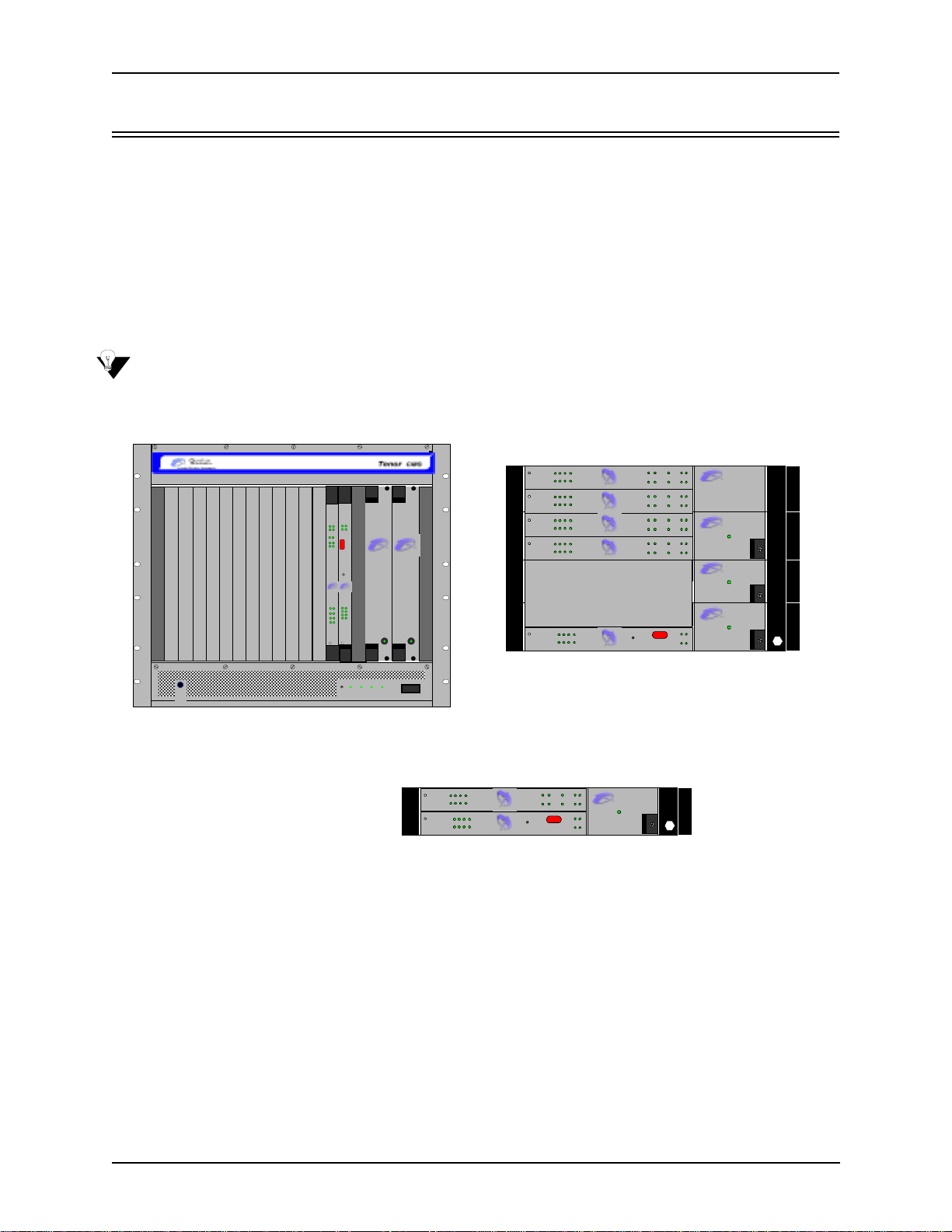
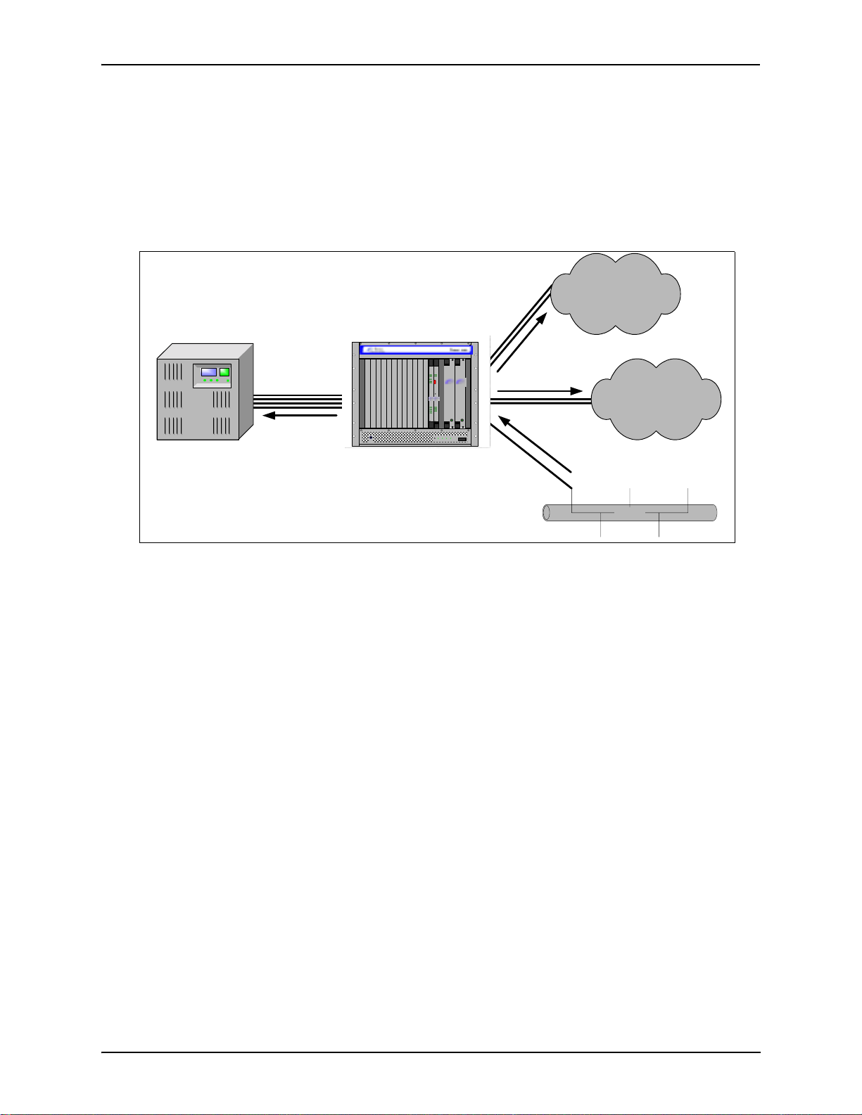
The Tenor Carrier MultiPath Switch (CMS) is a high-density VoIP (Voice over Internet Protocol) H.323
switch that digitizes voice and fax data and transmits it over th e IP network. Tenor CMS is available in three
configurations: CMS (14 slot), CMS960 (8 slot), and CMS240 (2 slot); each is a slotted, scalable system that
intelligently switches calls over both the IP network and the PSTN in order to ensure high quality voice. Tenor
CMS functions as a gateway, gatekeeper, and a border element. The gateway converts circuit switched calls to
VoIP calls, the gatekeeper performs IP call routing functions, and the border element distributes the call routing directories throughout the network.
Each Tenor CMS is available with either AC or DC input power.
NOTE: Figure 1-1 illustrates Tenor units with AC power.
Figure 1-1 Tenor CMS VoIP Switch
TM
StatusAlarm
StatusAl arm
CPU PCI
CPU
PCI
12
BankDSP
1
2
TX/RXLink
10/100
Ethernet
Reset
TM
Q
UINTUM
Q
UINTUM
TECHNOLOGIES,
TECHNOLOGIES,
INC.
INC.
Span
Status
LinkTX/RX
1
1
5
2
2
6
3
3
7
4
10/100
4
8
Ethernet
TM TM
Ground
Strap
TM
CPU
DS1
Hot Swap
Hot Swap
Reset +3.3V +5V +12V - 12V
Q
UINTUM
Q
UINTUM
T
ECHNOLOGIES, INC.
T
ECHNOLOGIES, INC.
TM
Fault Fault
0
1
Hot Swap
DS1
Hot Swap
DS1
Hot Swap
DS1
Hot Swap
DS1
Hot Swap
CPU
483726
15
Status
483726
15
Status
483726
15
Status
483726
15
Status
483726
15
Ethernet
10/100
QUINTUM
TECHNOLOGIES, INC.
Span
TM
TECHNOLOGIES, INC.
QUINTUM
Span
TM
QUINTUM
TECHNOLOGIES, INC.
Span
TM
QUINTUM
TECHNOLOGIES, INC.
Span
TM
QUINTUM
TECHNOLOGIES, INC.
Link TX/RX
TM
112
Link
Ethernet
DSP
10/100
TX/RX
Bank
2
112
Link
Ethern et
DSP
10/100
TX/RX
Bank
2
112
Link
Ethernet
DSP
10/100
TX/RX
Bank
2
112
Link
Ethernet
DSP
10/100
TX/RX
Bank
2
Reset
2
CMS960 (8 Slot)
CPU
PCI
CPU
PCI
CPU
PCI
CPU
PCI
CPU
PCI
Alarm
Status
Alarm
Stat us
Alarm
Stat us
Alarm
Status
A.C. P ow er Suppl y
A.C. P ow er Suppl y
Alarm
Status
A.C. P ow er Suppl y
QUINTUM
TECHNOL O GIES, INC.
QUINTUM
TECHNOL O GIES, INC.
Power
QUINTUM
TECHNOL O GIES, INC.
Power
QUINTUM
TECHNOL O GIES, INC.
Power
TM
TM
TM
TM
CMS (14 Slot)
Hot Sw ap
Hot Swap
DS1
Ethern et
CPU
15
Statu s
Span
483726
15
Link TX/RX
10/100
TM
QUINTUM
TECHNOLOGIES, INC.
TM
112
Link
Ethernet
10/100
Reset
Alarm
DSP
CPU
TX/RX
Bank
Status
PCI
2
Alarm
CPU
Statu s
PCI
2
QUINTU M
TECHNOLOGIES, I NC.
Power
A.C. Power Supply
TM
QUINTU M
TECHNOLOGIES, INC.
483726
CMS240 (2 Slot)
The slotted system architecture boasts peripheral cards, which interface to various Wide Area Networks
(WANs). Tenor CMS connects to T1/E1 lines operating in either a trunk circuit or line circuit configuration.
The individual spans within the Tenor CMS may connect to either the PSTN or to T1/E1 termination equipment on the user premises (i.e., PBX).
The high performance System Controller/CPU card provides up to four 10/100BaseT connections and one
RS-232 serial port connection; this card is an intelligent call routing engine which regulates system resources
and configuration while coordinating all voice traffic activity in the unit. The DS1, T1, and E1 cards provide
connections. The DS1 card also provides DSP processing (DSP is a signal processing resource; it performs
1-2 P/N 480-0005-00-15
Page 14

Chapter 1: Overview
functions such as voice packet generation and multiplexing). You can also use an individual DSP card for this
purpose.
Tenor CMS is managed by a unique Comman d Li ne Interface (CLI) management system. Through the CLI,
you can configure remote and local units. Just log on and configure items like chassis information, trunk
groups, signaling data, etc. In addition, you can assign specific numbers to be routed over the PSTN, rather
than IP. The CLI also provides a comprehensive on-line help system at your fingertips.
Quality of service is virtually guaranteed. SelectNet
the IP network performance for VoIP calls. If the performance characteristics become unacceptable—according to the specifications you assign— the call will be switched to the PSTN automatically. The unit’s simple
plug and play embedded system architecture brings VoIP technology to your network without changing your
existing telephony infrastructure. Your network stays as is and the call type is transparent to the user. This
technology boasts quality voice without compromising reliability.
™ T echnology provides a “safety net,” which monitors
Features
The Tenor CMS’s specific features are explained below.
Unique Design
T enor CMS is a compact PCI chassis that supports the transmission of Vo IP traffic via Ethernet connections. It
packs powerful VoIP features into one rack-mountable, slotted unit. In addition, the unit includes design features such as load sharing power supplies and peripheral cards; the chassis is available in AC or DC power.
A high performance backplane supports two types of chassis-side busses: TDM and packet. TDM supports
2048 full duplex channels; it is used for transporting circuit switched traffic. The packet bus is used for carrying packet-oriented data.
The slotted system architecture enables you to set the VoIP capabilities to suit your network’s needs; it is
available in three configurations: CMS (14 slot), CMS960 (8 slot), and CMS240 (2 slot) Through WAN interface cards and DSP resources, you configure the number of VoIP channels your network requires.
State-of-the-Art Configuration and Network Management
A System Controller/CPU card controls all activity in the chassis; it passes all configuration information you
set via CLI to the other peripheral cards (T1, E1, DS1) and DSP resources. In addition, the DS1 card enables
you to employ T1, E1, and DSP functionality in the same card. Through the System Controller/CPU card, you
can connect a PC’s console port as well as an Ethernet hub, switch, or router. In addition, the System Controller/CPU card provides one 10/100BaseT Ethernet port.
Once connected, the robust Command Line Interface (CLI) makes configuring a Tenor CMS easy. Through
the CLI, you are able to set all configuration parameters, such as chassis, signaling, and call type features. You
access the CLI through a simple telnet session. The state-of-the-art online help system, built into the CLI, provides help for all features and functionality. Just type help at any prompt, and data about that field will be displayed.
SelectNet™ Technology Safety Net
T enor CMS’ s built in SelectNet™ Technology safety net feature virtually guarantees that each call going VoIP
will not only be routed successfully, but will deliver high voice quality.
P/N 480-0005-00-15 1-3
Page 15

Chapter 1: Overview
If the network conditions for an IP call become unacceptable—according to the delay and packet loss specifications you configure—Tenor CMS will switch the call to the PSTN automatically and transparently. The
T enor CMS continuously monitors your data network for jitter, latency and packet loss, and transparently
switches customer calls to the PSTN when required.
Dynamic Call Routing
Tenor CMS’s intelligent call routing capabilities are state-of-the-art. The chassis automatically detects and
supports two call types: voice and fax.
Tenor CMS will first identify the call origination site —trunk circuit, line circuit, or IP routing group —and
then route the call according to any parameters you configure in the routing database. Each call may be routed
via circuit switched path between any two circuit groups, or compressed and transported via VoIP when connecting to an IP routing group. Trunk circuits are those that typically connect to another circuit switched network such as the PSTN. Line circuits typically connect to a termination device on the user premises, such as a
PBX.
Multiple Channels/Signaling Supported
Any combination of DS1, or T1 and E1 cards (up to 4) may be used to achieve up to 960 channels. The T enor
CMS provides support for most Channel Associated Signaling (CAS) and ISDN protocols.
Fractional T1/E1 Support
Tenor CMS supports Fractional T1/E1.
1-4 P/N 480-0005-00-15
Page 16
Chapter 1: Overview
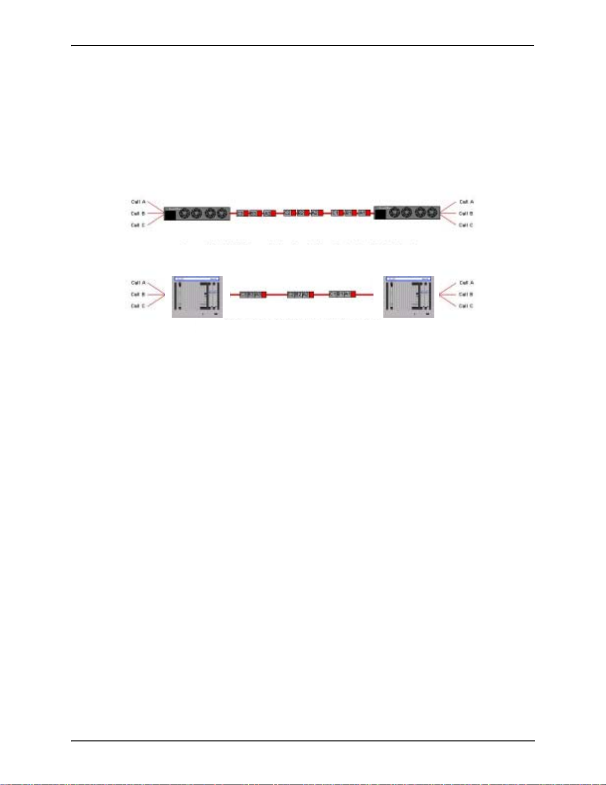
PacketSaver™
PacketSaver packet multiplexing technology reduces the amount of IP bandwidth required to support multiple
calls flowing between two endpoints. PacketSaver minimizes bandwidth usage by aggregating samp les from
multiple VoIP conversations and packing them into a larger IP packet with a single IP header. The process
removes the need to send a bulky IP header with individual voice packets. As a result, it eliminates the transmission of redundant information.
.
Conventional V oIP Transmission Sends Many Redundant Packet Headers
Tenor CMS
Tenor using PacketSaver to Minimize Bandwidth Usage
Tenor CMS
IVR/RADIUS support
Interactive Voice Response (IVR) is a feature of the Tenor CMS that enables you to offer services, such as Prepaid calling cards and Post-paid accounts, to your customers.
The Tenor CMS uses the RADIUS (Remote Authentication Dial-In User Service), for authenticating and
authorizing user access to the VoIP network, including ANI Authentication (T ypes 1 and 2). The RADIUS is a
standard protocol which provides a series of standardized message formats for transmitting and receiving
dialed information, account data and authorization codes between the network access gateway and the billing
server. As a result, the RADIUS enables the Tenor CMS to interoperate directly with billing server application
software from a wide range of vendors. To provide redundancy, the Tenor supports two RADIUS servers: Primary and Secondary.
Easy Connect to Console
Plugging a serial cable (for CPU) or null modem cable (for System Controller) between the System Controller/CPU card’s asynchronous RS-232 port and a serial port of your PC, will allow local chassis management.
Through the console connection, you are able to assign an IP address. In addition, if you are directly connected to the chassis, you are able to configure that chassis via Command Line Interface (CLI).
H.323 Gatekeeper Call Control Management
The Tenor CMS chassis’s built-in H.323 gatekeeper performs IP call routing functions, such as call control
and administrative services to another Tenor CMS unit, or another H.323 endpoint. The gatekeeper’s functionality complies with the H.323 industry specifications for voice control and management. See H.323 Gate-
keeper Services, later in this chapter, for more information.
P/N 480-0005-00-15 1-5
Page 17

Chapter 1: Overview
Powerful System Monitoring
There are many different ways to monitor the health of the unit, including LEDs and alarms. LEDs appear on
the front of the unit (for CMS -14 slot) and the front of WAN interface cards, as well as on the DSP cards, and
the System Controller/CPU card. The LEDs light up according to operations and alarms the system is experiencing. Through the Command Line Interface (CLI) management system, you can view a list of active system
alarms, as well as view an alarm history. Each alarm indicates the chassis’s operational status. Tenor CMS is
also SNMP-capable with HP® Openview™ support.
1-6 P/N 480-0005-00-15
Page 18
Chapter 1: Overview
Capabilities
The T enor CMS’ s specific capabilities are explained below . For illustration purposes, the Tenor CMS (14 slot)
is pictured.
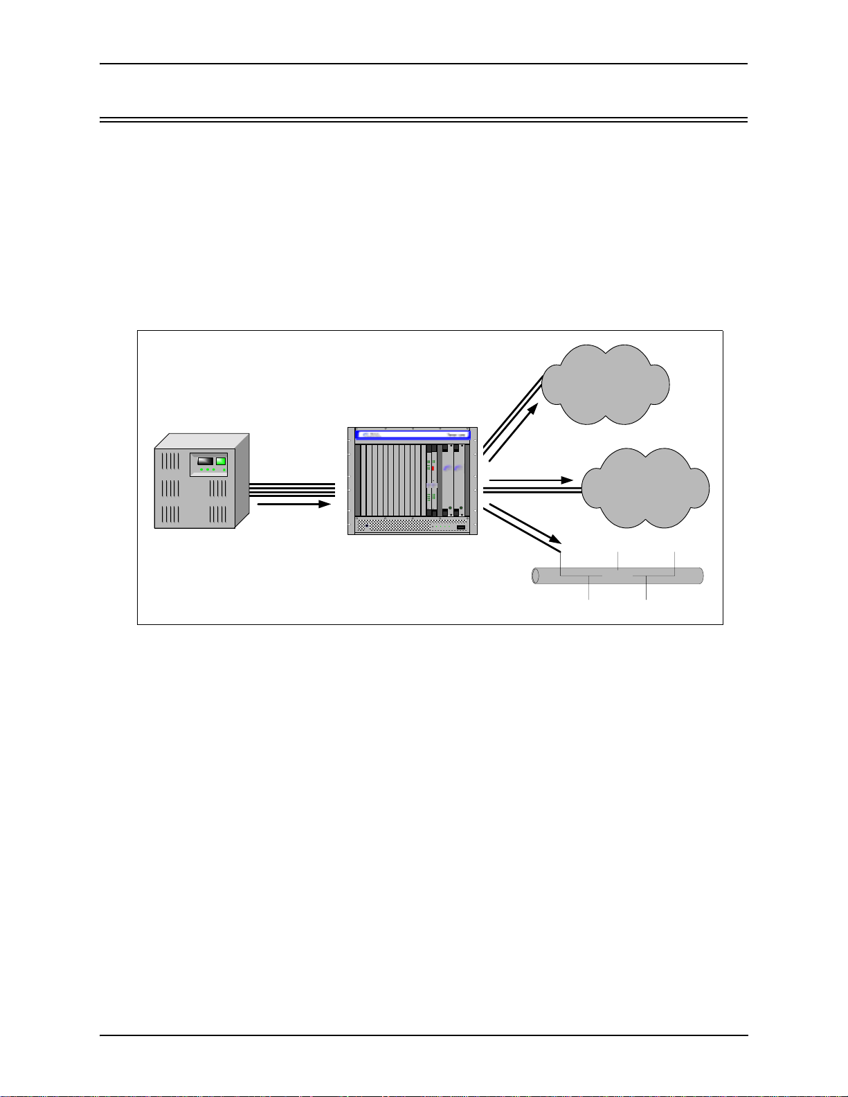
Line Circuit Originated Calls
Calls coming from a Line Circuit may be switched to either the data network as a VoIP call or to a Trunk Circuit typically for connection to another circuit switched network such as the PSTN. The routing decision made
by the Tenor CMS is based upon your con fig uration and the dialed number.
Figure 1-2 Line Circuit Call Routing
PBX
Line
Circuits
Circuit
Call
Ground
Strap
TM TM
Tenor CMS
CPU
12
1
2
Ethernet
Q
TECHNOLOGIES,
1
2
3
4
Hot Swap
StatusAlarm
PCI
BankDSP
TX/RXLink
10/100
UINTUM
INC.
Span
Status
5
6
7
8
DS1
StatusAlarm
CPUPCI
Reset
TM
TM
Q
UINTUM
TECHNOLOGIES,
INC.
LinkTX/RX
1
2
3
4
10/100
Ethernet
TM
CPU
Hot Swap
Reset +3.3V +5V + 12V -12V
Trunk
Circuits
TM
Q
UINTUM
Q
UINTUM
T
ECHNOLOGIES, INC.
T
ECHNOLOGIES, INC.
Trunk
Circuits
PSTN A
Circuit
Call
PSTN B
Fault Fault
0
1
Ethernet
(IP Network)
VOIP Call
Ethernet
P/N 480-0005-00-15 1-7
Page 19
Chapter 1: Overview
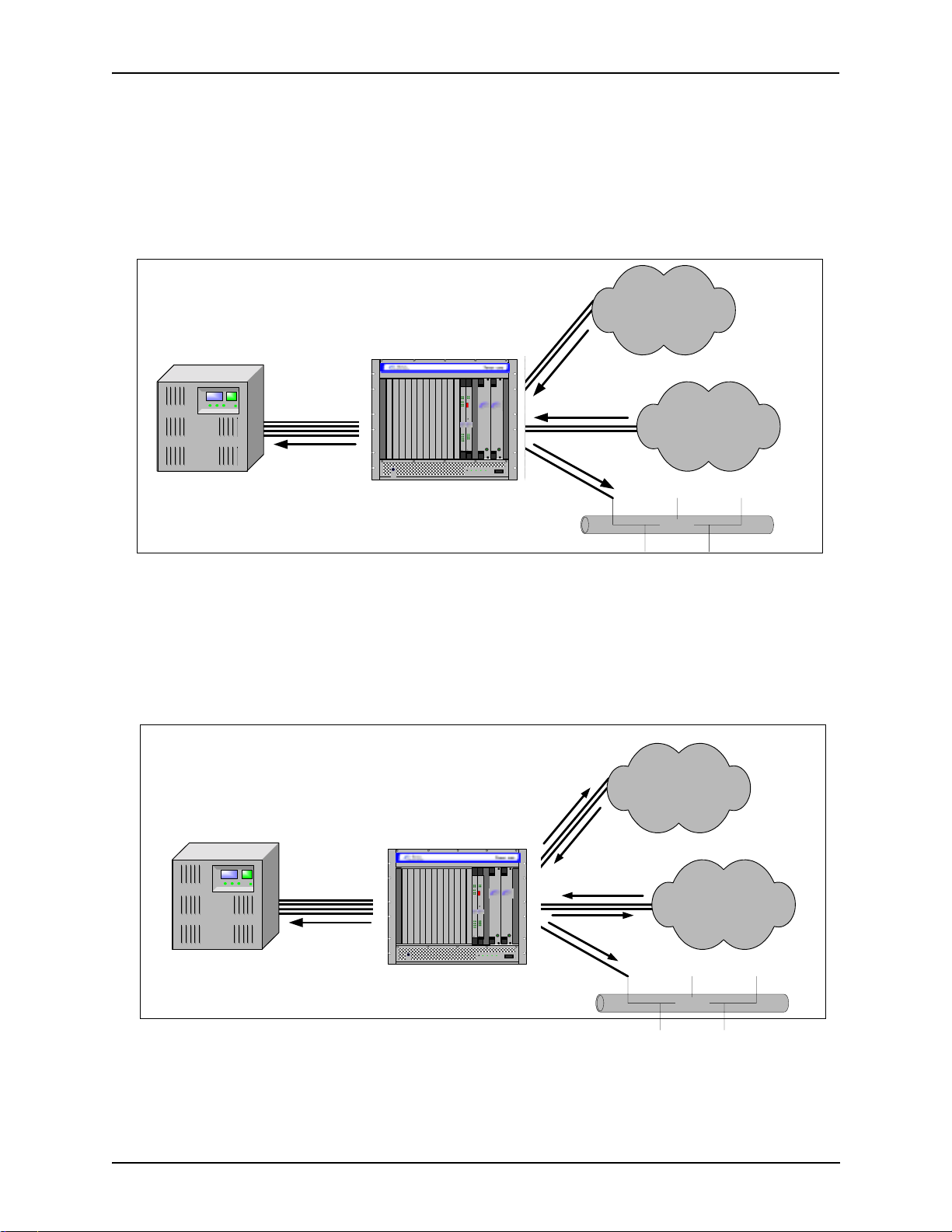
Trunk Circuit Originated Calls
A call coming from a Trunk Circuit may be switched to either the data network as a VoIP call, a Line Circuit,
or trunk typically for connection to a termination device on the users premises such as a PBX. The routing
decision made by the Tenor CMS is based upon your configuration and the dialed number.
Figure 1-3 Trunk Circuit Call Routing
PSTN A
Circuit
Call
VOIP Call
PSTN B
PBX
Line
Circuits
Circuit
Call
Ground
Strap
TM TM
Tenor CMS
CPU
12
1
2
Q
TECHNOLOGIES,
1
2
3
4
Hot Swap
StatusAlarm
PCI
BankDSP
TX/RXLink
10/100
Ethernet
UINTUM
INC.
Span
Status
5
6
7
8
DS1
StatusAlarm
CPUPCI
Reset
TM
TM
Q
UINTUM
TECHNOLOGIES,
INC.
LinkTX/RX
1
2
3
4
10/100
Ethernet
TM
CPU
Hot Swap
Reset +3.3V +5V + 12V -12V
Trunk
Circuits
TM
Q
UINTUM
Q
UINTUM
T
ECHNOLOGIES, INC.
T
ECHNOLOGIES, INC.
Fault Fault
0
1
Circuits
Ethernet
(IP Network)
Trunk
Ethernet
Intra-trunk Routing - “Hairpinning”
As a result of intra-trunk routing, incoming calls from a particular Trunk Circuit are switched by Tenor CMS
to be routed back out the same trunk circuit routing group.
Figure 1-4 Intra-Trunk Routing
PSTN A
Circuit
Call
VOIP Call
PSTN B
PBX
Line
Circuits
Circuit
Call
Ground
Strap
TM TM
Tenor CMS
12
1
2
10/100
Ethernet
Q
UINTUM
TECHNOLOGIES,
Span
Status
1
2
3
4
DS1
Hot Swap
StatusAlarm
PCICPU
BankDSP
TX/RXLink
TM
INC.
5
6
7
8
TM
StatusAlarm
CPU PCI
Reset
TM
Q
UINTUM
TECHNOLOGIES,
INC.
LinkTX/RX
1
2
3
4
10/100
Ethernet
CPU
Hot Swap
Reset +3.3V +5V +12V -12V
Trunk
Circuits
TM
Trunk
Q
UINTUM
Q
UINTUM
T
ECHNOLOGIES, INC.
T
ECHNOLOGIES, INC.
Fault Fault
0
1
Circuits
Ethernet
(IP Network)
Ethernet
1-8 P/N 480-0005-00-15
Page 20
Chapter 1: Overview
Data Network Calls
Calls coming from the data network can be routed to the Line circuit or Trunk circuit spans. The Tenor CMS
will route calls based upon the dialed number. If the number is configured as a local phone number, the call
will be sent to a Line circuit for termination, otherwise the call is considered a “Hop-Off call” and the Tenor
CMS sends it out through a Trunk circuit span, typically connected to the PSTN.
Figure 1-5 Data Network Call Routing
PSTN A
Circuit
Call
VOIP Call
PSTN B
PBX
Line
Circuits
Circuit
Call
Ground
Strap
TM TM
Tenor CMS
12
1
2
Q
TECHNOLOGIES,
2
CPU
BankDSP
TX/RXLink
10/100
Ethernet
UINTUM
INC.
Span
Status
1
3
4
DS1
Hot Swap
StatusAlarm
StatusAlarm
CPU PCI
PCI
Reset
TM
Q
UINTUM
TECHNOLOGIES,
INC.
LinkTX/RX
5
1
2
6
3
7
4
10/100
8
Ethernet
TM
CPU
Hot Swap
Reset +3.3V +5V +12V -12V
Trunk
Circuits
TM
Ethernet
Trunk
Circuits
Q
UINTUM
Q
UINTUM
T
ECHNOLOGIES, INC.
T
ECHNOLOGIES, INC.
TM
Fault Fault
0
1
(IP Network)
Ethernet
Other Call Routing Options
There are several routing tables you can configure via the Command Line Interface (CLI) to adjust how the
Tenor CMS unit routes specific calls. For example, you may want to configure 911 as a “bypass number”,
which means that all 911 calls coming into Tenor CMS from the line circuit will be routed directly to a Trunk
circuit presumably connected to a PSTN. Bypass calls are never routed over IP.
There are four types of routing databases you can configure: Bypass Directory Numbers (BPN), Local Directory Numbers (LDN), Hop-Off Directory Numbers (HDN) and Static Route. Bypass Directory Numbers are
directly routed from a Line circuit to a Trunk circuit. Local Directory Numbers are phone numbers that are
reachable through local Line Circuits. Hop-Off Directory Numbers are phone numbers that can be routed over
the IP to another Tenor location and then out to the Trunk circuit, possibly to the PSTN as a local call. Static
Routes are used between networks and other H.323 devices that are not registered to the network through the
Border Element (such as non-Quintum gateways).
Virtual Tie Line
Tenor CMS can emulate a tie trunk. It provides all of the functionality of a tie trunk, including the considerable cost savings, but eliminates the need for a PBX trunk to be configured, or marked as a tie trunk. A traditional tie trunk is a PBX-configured direct connection between two PBXs in separate locations. The tie trunk
bypasses the PSTN network.
Your PBX does not need any additional configuration. Tenor CMS treats all the trunks the same without compromising voice quality.
P/N 480-0005-00-15 1-9
Page 21

Chapter 1: Overview
Hop-off PBX Call
Hop-off numbers are phone number patterns for calls to be routed out trunks. They are entered in a
HopoffNumberDirectory and associated with TrunkCircuitRoutingGroups that govern the trunks where
matching calls should be sent.
Tenor CMS supports those Hop-off PBX calls where the destination Tenor CMS is programmed to route the
call to the PSTN via Trunk Circuit. (A Hop-off PBX call is a toll call which hops through a private network to
reduce or eliminate the toll charge.) The destination Tenor CMS unit is configured with the phone numbers to
be “supported” for this feature.
SNMP Support
The Tenor CMS unit supports Simp le Network Management Protocol (SNMP), the standard protocol used to
exchange network information between different types of networks. The Tenor CMS unit acts as an SNMP
agent—using HP Openview—to receive commands and issue responses to the network manager . The network
manager will then be able to perform certain functions, such as receiving traps from Tenor CMS.
Call Detail Recording
Through the Call Detail Record (CDR) feature, the Tenor CMS may generate a call record at the completion of
each call, typically for accounting purposes. A CDR is a string of data that contains call information such as
call date and time, call duration, calling party, and called party. Tenor CMS may store call detail records
locally or they can be sent to a CDR server within the network. The CDR contains sufficient information to
capture billing data, which can be used to create billing reports by third party billing software.
1-10 P/N 480-0005-00-15
Page 22

Chapter 1: Overview
H.323 Gatekeeper Services
Gatekeeper
A Gatekeeper in an H.323 network provides call control services and other services to H.323 endpoints (i.e.,
gateways, terminals, and MCUs). The Tenor CMS has a built-in H.323 gatekeeper which complies to the
H.323 industry specifications for voice control and management. The gatekeeper performs call routing functions for calls entering and exiting a site.
The Gatekeeper performs IP call routing functions, such as call control signaling and call authorization for
Gateways, IP phones, and H.323 terminals. The Gatekeeper communicates with other Gatekeepers through a
Border Element. When using a group of Tenor CMS units, you can assign one unit as the Gatekeeper for the
network. We recommend you configure each CMS as its own gatekeeper.
Tenor CMS supports gatekeeper to gatekeeper communication using LRQ (Location Request) messaging
scheme.
Zone Management
A zone is a group of H.323 defined endpoints controlled by a Gatekeeper. Endpoints can be gateways (i.e.,
Tenor CMS), terminals, and/or multipoint conferencing units (MCU s). Endpoints establish control channels
with a gatekeeper for registration, admission, security, and call routing information about the endpoint is sent
to the gatekeeper, including: IP address, unit type (gateway, terminal, or MCU) and routing information (such
as phone numbers, number patterns, etc.).
A collection of zones is an administrative domain. An administrative domain provides call routing services for
its zones through gatekeeper to gatekeeper messages or gatekeeper to border element messages (see Border
Element” for more information).
Call Registration
H.323 endpoints in the same zone register with the designated gatekeeper. When registration is complete and a
call is originated, the call request is sent to the gatekeeper. The call request provides the Gatekeeper with the
dialed number and requests the routing information. The gatekeeper confirms the dialed number and supplies
the endpoint with the destination IP address. For example, a Tenor CMS’s gatekeeper will act as the gatekeeper for that zone and all of the other endpoints will register with it.
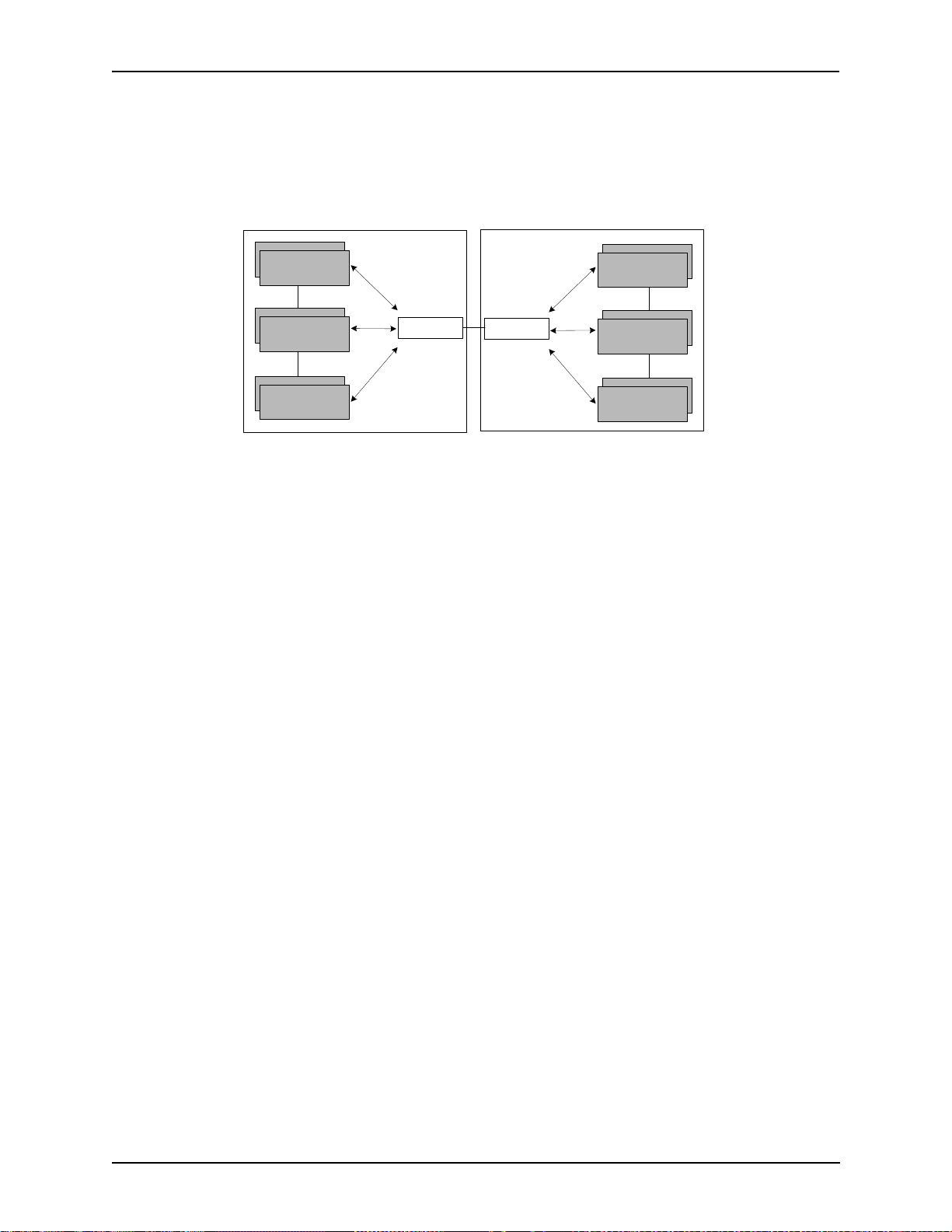
Border Element
The T enor CMS’ s gatekeeper uses a border element to gain access to the routing database of the administrative
domain for the purpose of call completion or any other services that involve communications with other endpoints out of the administrative domain. The border element functionality is built into the Tenor CMS unit,
along with the gateway and gatekeeper.
The primary function of the border element is to collect, manage, and distribute call routing information. A
gatekeeper will establish a service relationship with a border element; the gatekeeper provides its zones capabilities and the border element shares call routing capabilities of other zones in the administrative domain.
Through the border element, gatekeepers from multiple zones will be able to communicate.
A border element also establishes relationships with other border elements to route between administrative
domains. If a gatekeeper cannot resolve an address, it contacts the border element.
P/N 480-0005-00-15 1-11
Page 23
Chapter 1: Overview
In addition, if you are using more than one CMS unit, you can configure one of the border elements for that
zone. The T enor CMS unit provides two border elements: primary and secondary. These work together as one
entity to provide redundancy and fault tolerance; there are no hierarchical differences.
Gatekeeper
Zone
Gatekeeper
Zone
Gatekeeper
Zone
Administrative Domain
Border Element
Border Element
Administrative Domain
Gatekeeper
Zone
Gatekeeper
Zone
Gatekeeper
Zone
Call Services
Gatekeepers provide services such as addressing, authorization and authentication of terminals and gateways,
bandwidth management, accounting, billing, and charging. Gatekeepers also provide call-routing services.
Specifically, the Tenor CMS Gatekeeper provides the functions which follow:
Address Translation. The gatekeeper translates telephone numbers into IP addresses and vice versa. It performs Alias Address (phone number) to Transport Address (IP address) translation when an endpoint requests
service. The Gatekeeper uses a translation table to translate an Alias Address (an address such as an H.323
identifier that a user may not understand) to a transport address. The translation table is updated using Registration messages.
Autodiscovery. The gatekeeper is discovered in one of the following ways: An endpoint sends an IP broadcast called a Gatekeeper Request message (GRQ) message (which includes that correct gatekeeper name) to
discover a Gatekeeper OR the endpoint will discover a gatekeeper by its IP address.
Routing. The gatekeeper identifies the IP address of endpoints in its administrative domain. The gatekeeper
builds a routing database from information obtained from the border element and also from gateways and
H.323 endpoints.
Admissions Control. All H.323 endpoints must register and request permission to enter the gatekeeper’s
zone; the gatekeeper will confirm or deny access to the network. The gatekeeper authorizes network access
and protects the integrity of the network using Admissions Request (ARQ), Admissions Confirmation (ACF)
and Admissions Reject (ARJ) messages.
Configuration
For the Gatekeeper/Border Element functionality, the following items are configurable via Command Line
Interface (CLI):
• Primary Border Element IP Address. The IP address for the administrative domain’s Border Element
(the Border Element is internal to the Tenor CMS unit; it is used to establish relationships with other
P/N 480-0005-00-15 1-12
Page 24

Chapter 1: Overview
T enor CMS units in other companies). There is generally only one Primary Border Element in each organization.
• Secondary Border Element IP Address. The IP address for the alternate border element (the IP address
the Tenor CMS uses as a Border Element) is in the administrative zone. There is generally only one secondary Border Element in each organization.
• Discovery IP Address. The IP address a T enor CMS uses to communicate with a Gatekeeper for service.
• Discovery Port. The H.323 standard port a Tenor CMS uses to discover a Gatekeeper.
• Registration Port. The H.323 standard port a Tenor CMS uses to register itself with a Gatekeeper.
P/N 480-0005-00-15 1-13
Page 25

Chapter 2: Hardware Components
This chapter tells you what is contained in your hardware package. A description of each component is also
included.
Specifically, the following topics are covered:
! Chassis
! Power Supplies
! WAN Cards
! Cables
P/N 480-0005-00-15 2-1
Page 26

Chapter 2: Hardware Components
Hardware Description
Tenor CMS is available in CMS (14 slot), CMS960 (8 slot), and a CMS240 (2 slot).
The CMS (14 slot), CMS960 (8 slot), and CMS240 (2 slot) provide network connection and functionali ty
through WAN cards, DSP resource cards, and a system controller card/CPU card. Communication through the
chassis backplane is achieved through the following: packet bus and TDM bus. The packet bus is used for carrying packet-oriented data and the TDM bus is used for transporting circuit switched PCM traffic.
For the AC unit, the front side of the chassis provides access to WAN cards (T1/E1/DS1), power supplies, the
system controller card/CPU card, and DSP card; the rear side exposes the back portion of the transition cards
for network connection as well as power cord connection.
For the DC unit, the front side of the chassis provides access to WAN cards (T1/E1/DS1), DSP cards, the system controller/CPU card and power supplies. The rear side exposes the back portion of the transition cards for
network connections, as well as the circuit breakers, power receptacles and power plugs.
Through all of these units, you can connect up to four different points: Line Circuit (PBX), Trunk Circuit
(PSTN), Data network (Ethernet LAN) and a PC.
Board interoperability
Certain boards are supported in certain releases; the chart which follows lists which boards are supported
according to CMS release.
Table 2-1 Board supported according to CMS Release
Board Type
T1 Card Yes Yes Yes No Yes
E1 Card Yes Yes Yes No Yes
DS1 Card (with DSP
module)
DSP Card Yes No Yes N o No
System Controller Card Yes Yes Yes No No
CPU Card No No No Yes Yes
Release
P1.3.x
No Yes Yes Yes Yes
Release
P1.4.x and
higher
Release
P1.5.x
Release
P2.4.x
Release
P2.5.x
2-2 P/N 480-0005-00-15
Page 27
Chapter 2: Hardware Components
Chassis - CMS (14 Slot)
The chassis is the 19” rack-mountable unit which houses all WAN cards, System Controller/CPU cards, DSP
cards, and power supplies. The two system fans are installed at the top of the chassis. See the following sections for unit front and unit back details; both the AC version and DC versions are illustrated and explained.
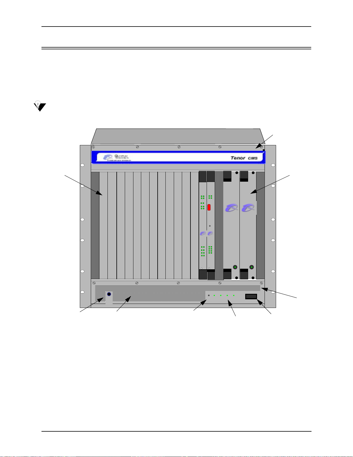
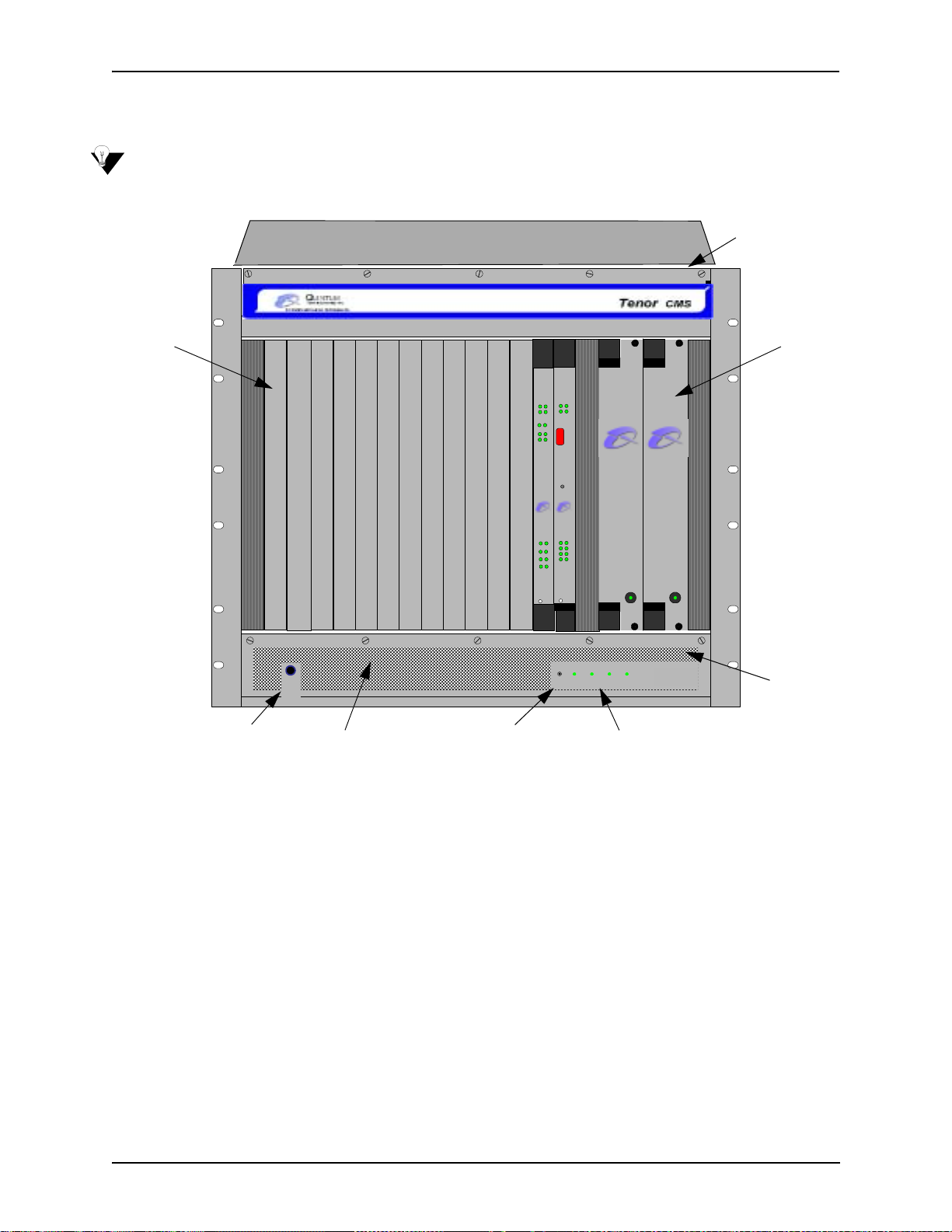
Front (with AC power)
NOTE: For pictorial purposes, Figure 2-1 shows the unit with 1 DS1 card and the CPU card.
Figure 2-1 Tenor CMS Front View - AC unit
TM
System Fans
WAN
Card Slots
StatusAlarm
StatusAlar m
CPU PCI
CPU
PCI
12
BankDSP
1
2
TX/RXLink
10/100
Ground Strap Socket
Ground
Strap
Air Inlet
TM TM
Reset
Button
Ethernet
Reset
TM
TM
Q
UINTUM
Q
UINTUM
TECHNOLOGIES ,
TECHNOLOGIES,
INC.
INC.
Span
Status
Link TX/RX
1
1
5
2
2
6
3
3
7
4
10/100
4
8
Ethernet
TM
CPU
DS1
Hot Swap
Hot Swap
Reset +3.3V +5V +12V -12V
QUINTUM
QUINTUM
T
ECHNOLOGIES , INC.
T
ECHNOLOGIES, INC.
Faul t Faul t
0
Chassis LEDs
1
On/Off Power
• Card Slots. Fourteen slots are available for WAN cards, DSP Resource Cards, DS1 cards, and the CPU/
System Controller Card.
Power
Supplies
Air Filter
• Power Supplies. Two load-sharing AC power supplies. The load sharing feature enables one power sup-
ply to take over if the other fails.
• System Fans. Two system fans, accessible through a swing down panel via thumb screws are used to
cool the chassis. These fans are “hot-swappable”, meaning you can remove/replace the fans while the
unit is operational.
• Reset Button. Enables you to reset the system. This function will be supported in a future release.
• Ground Strap Socket. A ground connection is provided for ESD protection.
P/N 480-0005-00-15 2-3
Page 28
Chapter 2: Hardware Components
• Air Filter. The Air Filter is accessible by opening the lower front panel. You do not have to turn off the
chassis. For cleaning, see Chapter 8: Diagnostics/Maintenance.
• Chassis LEDs. The LEDs are indicators as to the status of the four DC outputs of the power supplies.
When these are lit, they indicate the respective voltages are being output from the power supplies. When
unlit, the voltage is not being supplied. See Chapter 8: Diagnostics/Maintenance for more information.
• On/Off Power: A switch to turn power on and off.
Rear (with AC power)
NOTE: For pictorial purposes, Figure 2-2 is shown with 2 DS1 cards and the CPU Card.
Figure 2-2 Tenor CMS Rear View - AC unit
Link T X/RX
1
1
1
2
3
4
2
2
1
3
3
2
4
4
3
1
1
4
2
2
10/100
Ethernet
Console
3
3
4
4
Air Exhaust
WAN Card
Slots
Power Inlet
• WAN Card Slots. The rear of the T1, E1, or DS1 W AN cards (the transition modules), is used for net-
• Power Inlet. Inlet for which you insert the supplied AC power cord. The unit requires a 110-240 VAC.
• Earth Ground Stud. A Ground Stud is provided to connect to earth ground.
• Ground St rap Port. A ground connection is provided for ESD protection.
10/100
10/100
Ethernet
Ethernet
Link TX/RX
Link TX/RX
Off On
1
2
3
4
Config
Link TX/RX
Link TX/RX
CPU
DS1
DS1
10
A
M
100-240VAC
50-60Hz
P
Earth Ground Stud
Label
© Copyright 2001 Quintum Technologies Inc.
Ground Strap Port
work connection. The quantity will vary depending upon the number of WAN cards you have inserted.
2-4 P/N 480-0005-00-15
Page 29
Chapter 2: Hardware Components
Front (with DC Power)
NOTE: For pictorial purposes, Figure 2-3 shows the unit with 1 DS1 card and the CPU card.
Figure 2-3 Tenor CMS Front View - DC unit
System Fans
TM
Card Slots
Ground Strap Socket
Ground
Strap
Air Inlet
TM TM
Reset
Button
StatusAlarm
StatusAlarm
CPU PCI
CPU
PCI
12
BankDSP
1
2
TX/RXLink
10/100
Ethernet
Reset
TM
TM
QUINTUM
QUINTUM
TECHNOLOGIES ,
TECHNOLOGIES ,
INC.
INC.
Span
Status
Link TX/RX
1
1
5
2
2
6
3
3
7
4
10/100
4
8
Ethernet
TM
CPU
DS1
Hot Swap
Hot Swap
Reset +3.3V +5V +12V -12V
QUINTUM
QUINTUM
T
ECHNOLOGIES, INC.
T
ECHNOLOGIES, INC.
Fault Fa ult
0
Chassis LEDs
Power
Supplies
1
Air Filter
• Card Slots. Fourteen slots are available for WAN cards (T1/E1/DS1), DSP cards, and the CPU/System
Controller card.
• Power Supplies. Two load-sharing DC power supplies. The load sharing feature enables one power sup-
ply to take over if the other fails.
• System Fans. Two system fans, accessible through a swing down panel via thumb screws, are used to
cool the chassis. These fans are “hot-swappable”, meaning you can remove/replace the fans while the
unit is operational.
• Reset Button. Enables you to reset the system. This function will be supported in a future release.
• Ground Strap Socket. A ground connection is provided for ESD protection.
• Air Filter. The Air Filter is accessible by opening the lower front panel. You do not have to turn off the
chassis. For cleaning, see Chapter 8: Diagnostics/Maintenance.
• Chassis LEDs. The LEDs are indicators as to the status of the four voltage supplies. When these are lit,
they indicate the respective voltages are being output from the power supplies. When unlit, the voltage is
not being supplied. See Chapter 8: Diagnostics/Maintenance for more information.
P/N 480-0005-00-15 2-5
Page 30
Chapter 2: Hardware Components
Rear (with DC power)
NOTE: For pictorial purposes, Figure 2-4 is shown with 1 DS1 card and the CPU card.
Figure 2-4 Tenor CMS Rear View - DC unit
Link TX/RX
Card
Slots
1
2
3
4
1
2
3
4
10/100
Ethernet
Console
1
2
3
4
1
2
3
4
Air Exhaust
10/100
Ethernet
Link TX/RX
Off On
1
2
3
4
Config
Link TX/RX
Earth Ground
Terminal
© Copyright 2001 Quintum Technologies Inc.
CPU
10
DS1
-48 |RTN|
Off On
0 1
Off On
0 1
-48 |RTN|-48 |RTN|
-48 |RTN|
ESD Socket
Power Receptacle
Power Plug
Power Plug
Power Receptacle
Circuit Breaker
• Card Slots. The rear of the cards requiring a transition module (T1, E1, DS1, CPU) is used for network
connection. The quantity will vary depending upon the number of cards you have inserted.
• Power Plug. Provides wire connections to the -42 to -60 VDC power from the DC feed(s) to the power
receptacles. Both may be used, but only one is required (one must have the power connected to its power
inlet connector).
• Power Receptacle. Power inlet receives DC power from the power plug.
• Circuit Breaker. There is one circuit breaker for each power connection; an arrow from each one indi-
cates which breaker controls which power receptacle connection. The top circuit breaker controls the left
power receptacle; the bottom circuit breaker controls the right power receptacle. When you push the
rocker to ON, the breaker will be closed (a red indicator shows the user that the contacts are closed).
When you push the rocker to OFF, the contacts will open. Both circuit breakers must always be open,
even if only one power source is connected to the chassis, to ensure all power is disconnected from the
power supplies.
• Earth Ground Terminal An earth ground terminal is provided to connect to a supplemental earth
ground.
• ESD Socket. A ground connection is provided for ESD protection.
2-6 P/N 480-0005-00-15
Page 31

Chapter 2: Hardware Components
Chassis - CMS960 (8 Slot)
The chassis is a 19” rack-mountable unit which houses all WAN cards, System Controller/CPU cards, DSP
cards, and power supplies. See the following sections for unit front and unit back details; both the AC version
and DC versions are illustrated and explained. The slots are 1-8; the bottom slot being slot number 1.
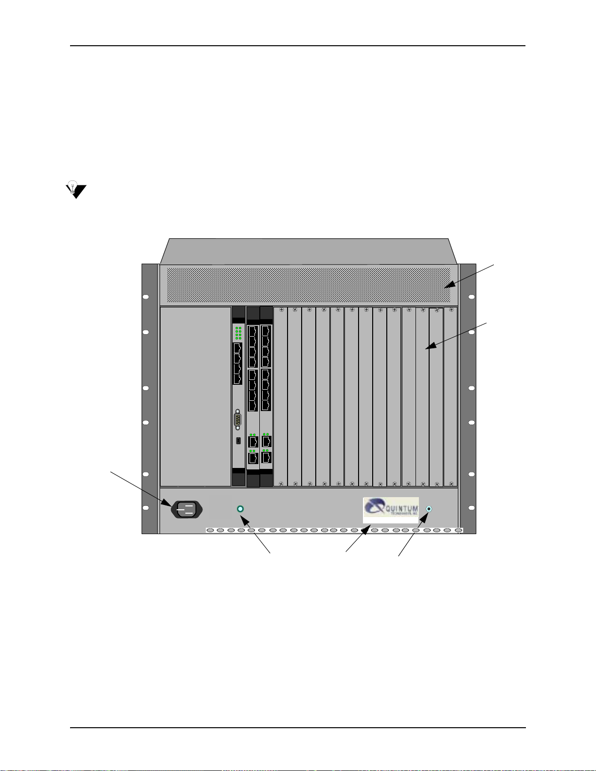
Front (with AC power)
NOTE: For illustration purposes, Figure 2-5 shows the unit with 4 DS1 cards and the CPU card.
Figure 2-5 Tenor CMS960 Front View - AC unit
Card Slots
QUINTU M
Hot Sw a p
DS1
Hot Sw a p
DS1
Hot Sw a p
DS1
Hot Sw a p
DS1
Hot Swap
CPU
483726
483726
483726
483726
Ethernet
10/100
TECHNOLOGIES, INC.
15
Status
Span
TM
TECHNOLOGIES, INC.
QUINTUM
15
Status
Span
TM
QUINTU M
TECHNOLOGIES, INC.
15
Status
Span
TM
QUINTUM
TECHNOLOGIES, INC.
15
Status
Span
TM
QUINTU M
TECHNOLOGIES, INC.
483726
15
Link TX/RX
TM
112
Link
Ethernet
10/100
TX/RX
Link
Ethernet
10/100
TX/RX
Link
Ethernet
10/100
TX/RX
Link
Ethern et
10/100
TX/RX
Reset
Alarm
DSP
CPU
Bank
Stat us
PCI
2
112
Alarm
DSP
CPU
Bank
Stat us
PCI
2
112
Alarm
DSP
CPU
Bank
Stat us
PCI
2
112
Alarm
DSP
CPU
Bank
Stat us
PCI
CPU
PCI
A.C. P ow er S uppl y
A.C. P ow er S uppl y
Alarm
Stat us
A.C. P ow er S uppl y
2
2
QUINTU M
TEC HNOL O G IES , INC.
QUINTU M
TEC HNOL O G IES , INC.
Power
QUINTU M
TEC HNOL O G IES , INC.
Power
QUINTU M
TEC HNOL O G IES , INC.
Power
TM
TM
TM
TM
Power
Supplies
Wrist Strap Ground Socket
• Card Slots. Eight slots are available for WAN cards, DSP Resource Cards, DS1 cards, and the CPU/
System Controller Card.
• Power Supplies. Three load-sharing AC power supplies; two are installed in the unit. Power supplies act
in a load sharing manner. Two power supplies are standard, the third power supply is optional, and
ensures redundancy if any one of the three fail.
• Wrist Strap Ground Socket. Socket available in which to connect an ESD wrist strap for ESD protec-
tion.
P/N 480-0005-00-15 2-7
Page 32

Chapter 2: Hardware Components
Rear (with AC power)
NOTE: For illustration purposes, Figure 2-6 is shown with 4 DS1 cards and the CPU card.
Figure 2-6 Tenor CMS960 Rear View - AC unit
Link TX/RX
Link TX/RX
Ethernet
10/100
1
2
3
4
5
6
7
8
Link TX/RX
Link TX/RX
Ethernet
10/100
1
2
3
4
5
6
7
8
Link TX/RX
Link TX/RX
Ethernet
10/100
1
2
3
4
5
6
7
8
Link TX/RX
Link TX/RX
Ethernet
10/100
1
2
3
4
5
6
7
8
1
2
483726
2
Ethernet
Console
Off
On
123
10/100
3
4
Strain Relief
Mount
DS1
DS1
DS1
DS1
1
0
Config
CPU
4
15
Link
TX/RX
Card Slots
Power Inlet
On/Off Power Switch
Fuse
Supplementary
Earth Ground
Wrist Strap Ground Socket
• Card Slots. Eight slots are available for WAN cards, DSP Resource Cards, DS1 cards, and the CPU/
System Controller Card.
• Power Inlet. Inlet for which you insert the supplied AC power cord. The unit requires 110-240 VAC.
• On/Off Power: A switch to turn power on and off.
• Strain Relief Mount. The S train Relief Mount enables you to connect the power cord strain relief to the
unit. A power cord strain relief is a plastic device designed to avoid accidental power down of the Tenor
CMS (i.e., if the power cord is accidentally pulled, the strain relief will relieve pressure put on the cord.)
• Fuse. Replaceable fuse. See Chapter 8: Diagnostics/Maintenance for more information.
• Supplementary Earth Ground. A supplementary earth ground connection is provided.
• Wrist Strap Ground Socket. Socket available in which to connect an ESD wrist strap for ESD protec-
tion.
2-8 P/N 480-0005-00-15
Page 33

Chapter 2: Hardware Components
Front (with DC Power)
NOTE: For illustration purposes, Figure 2-7 shows the unit with 4 DS1 cards and the CPU card.
Figure 2-7 Tenor CMS960 Front View - DC unit
QUINTU M
TECHNOLOGIES, INC.
15
Status
Span
TM
TECHNOLOGIES, INC.
QUINTU M
15
Status
Span
TM
QUINTU M
TECHNOLOGIES, INC.
15
Status
Span
TM
QUINTU M
TECHNOLOGIES, INC.
15
Status
Span
TM
QUINTU M
TECHNOLOGIES, INC.
483726
15
Link TX/RX
TM
1
1
2
Link
Ethernet
10/100
TX/RX
1
2
Link
Ethern et
10/100
TX/RX
1
2
Link
Ether net
10/100
TX/RX
1
2
Link
Ethernet
10/100
TX/RX
Alarm
DSP
CPU
Bank
Stat us
PCI
2
1
Alarm
DSP
CPU
Bank
Stat us
PCI
2
1
Alarm
DSP
CPU
Bank
Stat us
PCI
2
1
Alarm
DSP
CPU
Bank
Stat us
PCI
2
D.C. P ow er S uppl y
QUINTU M
TEC HNOL O G IES , INC.
QUINTU M
TEC HNOL O G IES , INC.
Power Alar m
QUINTU M
TEC HNOL O G IES , INC.
Power Alar m
TM
Power Supplies
TM
TM
D.C. P ow er S uppl y
TM
QUINTU M
TEC HNOL O G IES , INC.
Alarm
Reset
CPU
Stat us
PCI
2
Power Alar m
D.C. P ow er S uppl y
Card Slots
Hot Swap
DS1
Hot Swap
DS1
Hot Sw a p
DS1
Hot Sw ap
DS1
Hot Sw a p
CPU
483726
483726
483726
483726
Ether net
10/100
Wrist Strap Ground Socket
• Card Slots. Eight slots are available for WAN cards (T1/E1/DS1), DSP cards, and the CPU/System
Controller card.
• Power Supplies. Three load-sharing AC power supplies; two are installed in the unit. Power supplies act
in a load sharing manner. Two power supplies are standard, the third power supply is optional, and
ensures redundancy if any one of the three fail.
• Wrist Strap Ground Socket. Socket available in which to connect an ESD wrist strap for ESD protec-
tion.
P/N 480-0005-00-15 2-9
Page 34

Chapter 2: Hardware Components
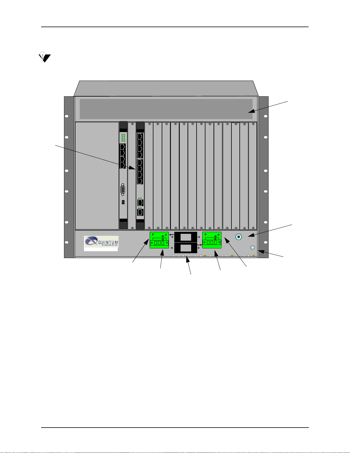
Rear (with DC power)
“CAUTION: This equipment is designed to permit the connection of the earthed conductor of the d.c. supply
circuit to the earthing conductor at the equipment. See installation instructions.”
Figure 2-8 Tenor CMS960 Rear View - DC unit
Ethern et
Link TX/RX
Link TX/RX
10/100
1
2
3
4
5
6
7
8
Link TX/RX
Link TX/RX
Ethern et
10/100
1
2
3
4
5
6
7
8
Ethern et
Link TX/RX
Link TX/RX
10/100
1
2
3
4
5
6
7
8
Link TX/RX
Link TX/RX
Ethern et
10/100
1
2
3
4
5
6
7
8
483726
1
2
15
Link
TX/RX
Ethern et
Console
Off On
123
10/100
2
3
4
Circuit Breaker
n
O
1
n
O
1
O
f
f
0
O
f
f
0
-48 RTN -48 RTN
A
DS1
DS1
DS1
DS1
B
Config
CPU
4
Card
Slots
Power Terminal
Supplementary
Earth Ground
Wrist Strap Ground Socket
• Card Slots. The rear of the cards requiring a transition module (T1, E1, DS1, CPU) is used for network
connection. The quantity will vary depending upon the number of cards you have inserted.
• Strain Relief Mount. The S train Relief Mount enables you to connect the power cord strain relief to the
unit. A power cord strain relief is a plastic device designed to avoid accidental power down of the Tenor
CMS (i.e., if the power cord is accidentally pulled, the strain relief will relieve pressure put on the cord.)
• Power Terminal. Provides screw terminal wire connections to the -40 to -60 VDC power.
• Supplementary Earth Ground. A supplementary earth ground connection is provided.
• Circuit Breaker. There is one circuit breaker for each power connection; lettering on each one indicates
which breaker controls which power receptacle connection. When you push the rocker to ON, the
breaker will be closed (a red indicator shows the user that the contacts are closed). When you push the
rocker to OFF, the contacts will open. To ensure all power is disconnected from unit, open both circuit
breakers.
• Wrist Strap Ground Socket. Socket available in which to connect an ESD wrist strap for ESD protec-
tion.
2-10 P/N 480-0005-00-15
Page 35

Chapter 2: Hardware Components
Chassis- CMS240 (2 slot)
The 2 slot chassis is a 19” rack-mountable unit which houses all WAN cards, System Controller/CPU cards,
DSP cards, and a power supply. See the following sections for unit front and unit back details; both the AC
version and DC versions are illustrated and explained. There are two slots, the bottom slot is slot number 1 and
contains the CPU card.
Front View (with AC power)
Figure 2-9 Tenor CMS240 Front View - DC unit
Card Slots
QUINTUM
Hot Swa p
DS1
Hot S w ap
CPU
483726
483726
Ethernet
10/100
TECHNOL OGIES , INC.
15
Status
Span
TM
QUINTUM
TECHNOLOGIES, INC.
15
Link TX/R X
TM
Link
Ethernet
10/100
Reset
DSP
TX/RX
Bank
Alarm
CPU
Sta tus
PCI
2
Alarm
CPU
Sta tus
PCI
2
A.C. Pow er Supply
QUINTUM
TE CHNO L O G IES, INC.
Power
TM
1
1
2
Power Supply
Wrist Strap
Ground
Socket
• Card Slots. Two slots are available for WAN cards (T1/E1/DS1), DSP cards, and the CPU/System Con-
troller card.
• Power Supply. One AC Power Supply.
• Wrist Strap Ground Socket. Socket available in which to connect an ESD wrist strap for ESD protec-
tion.
P/N 480-0005-00-15 2-11
Page 36

Chapter 2: Hardware Components
Rear View (with AC power)
Figure 2-10 Tenor CMS240 Rear View - AC unit
Strain Relief Mount
1
0
Power Inlet
Fuse
DS1
CPU
Link TX/RX
Link TX/RX
Ethernet
10/100
1
2
3
4
5
6
7
8
Ethernet
Console
Config
Off
On
123
4
10/100
3
4
1
2
483726
15
Link
TX/RX
2
Wrist Strap Ground Socket
Supplementary
Earth Ground
Card Slots
On/Off Power Switch
• Strain Relief Mount. The S train Relief Mount enables you to connect the power cord strain relief to the
unit. A power cord strain relief is a plastic device designed to avoid accidental power down of the Tenor
CMS (i.e., if the power cord is accidentally pulled, the strain relief will relieve pressure put on the cord).
• Power Inlet. Inlet for which you insert the supplied AC power cord. The unit requires 110-240 VAC.
• On/Off Power Switch. A switch to turn power on and off.
• Fuse. Replaceable fuse. See Chapter 8: Diagnostics/Maintenance for more information.
• Supplementary Earth Ground. A supplementary earth ground connection is provided.
• Card Slots. The rear of the cards requiring a transition module (T1, E1, DS1, CPU) is used for network
connection. The quantity will vary depending upon the number of cards you have inserted.
• Wrist Strap Ground Socket. Socket available in which to connect an ESD wrist strap for ESD protec-
tion.
2-12 P/N 480-0005-00-15
Page 37

Front view (with DC power)
Figure 2-11 Tenor CMS240 Front View - DC unit
QUINTUM
Hot Swa p
DS1
Hot S w ap
CPU
483726
483726
Ethernet
10/100
TECHNOLOGIES, INC.
15
Status
Span
TM
QUINTUM
TECHNOLOGIES, INC.
15
Link TX/R X
TM
Chapter 2: Hardware Components
1
1
2
Link
Ethernet
10/100
Reset
DSP
TX/RX
Bank
Alarm
CPU
Sta tus
PCI
2
Alarm
CPU
Sta tus
PCI
2
D.C. Pow er Supply
QUINTUM
TE CHNO L O G IES, INC.
Power Alarm
TM
Card Slots
Power Supply
Wrist Strap
Ground
Socket
• Card Slots. Two slots are available for WAN cards (T1/E1/DS1), DSP cards, and the CPU/System Con-
troller card.
• Power Supply. One DC Power Supply.
• Wrist Strap Ground Socket. Socket available in which to connect an ESD wrist strap for ESD protec-
tion.
P/N 480-0005-00-15 2-13
Page 38

Chapter 2: Hardware Components
Rear View (with DC power)
“CAUTION: This equipment is designed to permit the connection of the earthed conductor of the d.c. supply
circuit to the earthing conductor at the equipment. See installation instructions.”
Figure 2-12 Tenor CMS Rear View - DC unit
Circuit Breaker
Ethernet
Link TX/R X
Link TX/R X
n
O
O
f
f
0
1
-48 RTN
DS1
Config
CPU
Off On
123
4
10/100
1
2
3
4
5
6
7
8
Ethernet
Console
10/100
3
4
1
2
483726
15
Link
TX/RX
2
Strain Relief Mount
Power Terminal
Supplementary
Earth Ground
Card Slots
Wrist Strap Ground Socket
• Circuit Breaker. There is one circuit breaker for each power connection; lettering on each one indicates
which breaker controls which power receptacle connection. When you push the rocker to ON, the
breaker will be closed (a red indicator shows the user that the contacts are closed). When you push the
rocker to OFF, the contacts will open. To ensure all power is disconnected from unit, open both circuit
breakers.
• Strain Relief Mount. The S train Relief Mount enables you to connect the power cord strain relief to the
unit. A power cord strain relief is a plastic device designed to avoid accidental power down of the Tenor
CMS (i.e., if the power cord is accidentally pulled, the strain relief will relieve pressure put on the cord.)
• Power Terminal. Provides screw terminal wire connections to the -40 to -60 VDC power.
• Supplementary Earth Ground. A supplementary earth ground connection is provided.
• Card Slots. The rear of the cards requiring a transition module (T1, E1, DS1, CPU) is used for network
connection. The quantity will vary depending upon the number of cards you have inserted.
• Wrist Strap Ground Socket. Socket available in which to connect an ESD wrist strap for ESD protec-
tion.
2-14 P/N 480-0005-00-15
Page 39

Chapter 2: Hardware Components
System Controller Card (Available for CMS P1.5.x )
The System Controller card is a single slot Compact PCI (Peripheral Component Interconnect) card which
provides the central management functionality for the Tenor CMS unit. The controller card is the call routing
engine for the system and coordinates all activity within the chassis, including system resources management/
monitoring.
The system controller card provides an interface for transferring VoIP data throughout the system and communicating with other network cards via PCI bus.
As the central point of system resource management, the system controller card implements the intelligent call
routing and IP call signaling. The card also acts as an interface through which the user is able to perform network and system management functions. The system controller card is always inserted in slot 14 for the CMS
(the slot nearest the power supplies, identified with a red card guide). See Figure 2-13.
Figure 2-13 System Controller Card
10/100
Ethernet
10/100 Ethernet Port
Console Port
Reset
Console
Abort
RST
ABT
BFL CPU
CPCI PCI
.295
LEDs
.531
TM
10/100 Base-T Ethernet port. This port provides one RJ-45 jack for connection to a 10/100 BASE-T Ethernet LAN switch or hub via RJ-45 cable. The input/output signals are listed in Table 2-2.
P/N 480-0005-00-15 2-15
Page 40

Chapter 2: Hardware Components
Figure 2-14 10/100 Ethernet Port Pin order
Table 2-2 Input/Output Signals for 10/100 Ethernet Port
Pin # Signal Definition Color
1 TX + Transmit Data White w/orange
2 TX - Transmit Data Orange
3 RX + Receive Data White w/green
4 RSVD Reserved Blue
5 RSVD Reserved White w/blue
6 RX - Receive Data Green
7 RSVD Reserved White w/Brown
8 RSVD Reserved Brown
2-16 P/N 480-0005-00-15
Page 41

Chapter 2: Hardware Components
Console port. This RS-232 connector is used for connection to a PC’s serial port via DB-9 null modem cable
at 38400 BPS 8N1, and no flow control. The input/output signals are listed in Table 2-3.
Figure 2-15 DB-9 Female Connector Pin Order
5 4 3 2 1
9 8 7 6
Table 2-3 Serial Null Modem Cable DB-9 Connector Pinouts
Pin # Function Description
1 RSVD Reserved
2 RXD Receive Data
3 TXD Transmit Data
4 RSVD Reserved
5 GND Signal Ground
6 RSVD Reserved
7 RSVD Reserved
8 RSVD Reserved
9 RSVD Reserved
RST. Resets the System Controller board along with the entire chassis.
ABT. Abort recessed push button switch used for int ernal Quint um use only.
LEDs. LEDs provide a high level indication of the system controller card activity. Basic definitions follow.
See Chapter 8: Diagnostics/Maintenance for a detailed description for troubleshooting purposes.
• BFL. Steady yellow light indicates the board has failed.
• CPU. Green light indicates the CPU bus is active.
• PCI. Green light indicates that the local PCI bus is busy.
• CPCI. Green light indicates the Compact PCI (CPCI) bus is busy.
P/N 480-0005-00-15 2-17
Page 42

Chapter 2: Hardware Components
CPU Card (Available for CMS P2.x.x)
The CPU card is a single slot Compact PCI (Peripheral Component Interconnect) controller card which provides the central management functionality for the Tenor CMS unit. The controller card is the call routing
engine for the system and coordinates all activity within the chassis, including system resource management/
monitoring. The CPU card provides an interface for transferring VoIP data throughout the system and communicating with the other network cards via PCI bus.
As the central point of system resource management, the CPU card implements the intelligent call routing and
IP call signaling. The card also acts as an interface through which the user is able to perform network and system management functions.
When CPU card is inserted in the slot, it connects to an associated Rear Transition Module (RTM) in the rear
of chassis.
NOTE: For the purposes of this document, the term “CPU” card indicates the CPU application card and
transition module as a single unit.
Through the CPU card, you are able to perform system functions, such as resetting the system, connect to an
Ethernet hub/switch, or connect to a PC. In addition, LEDs provide a high level indication of system and chassis activity .
NOTE: All Input/Output ports and connections for the CPU card are located on the rear panel of the card.
For the CMS (14 slot), the CPU card is always inserted in slot 14 — the slot nearest the power supplies with a
red card guide—when viewing from the front of the chassis. For CMS960 (8slot), and the CMS240 (slot), the
CPU card is always inserted in slot 1, the bottom slot.
2-18 P/N 480-0005-00-15
Page 43

Front View
Chapter 2: Hardware Components
Figure 2-16 CPU Card (Front)
Card Activity LEDs
Port
Ethernet LEDs
StatusAlarm
CPU PCI
Reset
Q
UINTUM
TECHNOLOGIES, INC.
Link TX/RX
1
2
3
4
10/100
Ethernet
CPU
Hot Swap
Reset
TM
TM
Hot Swap LED
Card Activity LEDs. LEDs provide a high level indication of the CPU card activity. Basic definitions follow.
See Chapter 8: Diagnostics/Maintenance for a detailed description and troubleshooting purposes.
• Alarm. Indicates an alarm has been generated.
• Status. Green light. When a user logs in through telnet, the LED turns to amber.
• CPU. Green light indicates the CPU bus is active.
• PCI. Green light indicates that the local PCI bus is busy.
Port. For future use.
Reset. Resets the CPU card along with the entire chassis.
Ethernet LEDs. The CPU card contains four Link and TX/RX Status LEDs, viewable from the front of the
chassis, to provide a high level indication of the system operational mode and chassis activity , including alarm
activity. Each Link LED relates to one Ethernet line on the rear of the cards.
P/N 480-0005-00-15 2-19
Page 44

Chapter 2: Hardware Components
Hot Swap. For future use.
Rear View
Link LEDs
Figure 2-17 CPU Card (Rear)
Link TX/RX
1
2
3
4
1
10/100 Ethernet ports
10/100
Ethernet
2
3
4
Console Port
Console
Config Switch
(Quintum Use Only)
Config
CPU
Off On
1
2
3
4
Link LEDs. The CPU card contains four Link and TX/RX Status LEDs, viewable from the rear of the chassis,
to provide a high level indication of the system operational mode and chassis activity.
10/100 Base-T Ethernet port. The Ethernet port (one port is functional; the other three ports are not used)
provides an RJ-45 jack for an individual connection to a 10/100 Ethernet LAN switch or hub via RJ-45 cable.
The Ethernet port is individually configured with a unique IP and MAC address.
Figure 2-18 10/100 BASE-T Ethernet Port Pin Order
2-20 P/N 480-0005-00-15
Page 45

Chapter 2: Hardware Components
Table 2-4 Input/Output 10/100 Ethernet port
Pin # Signal Definition Color
1 TX + Transmit Data White w/orange
2 TX - Transmit Data Orange
3 RX + Receive Data White w/green
4 RSVD Reserved Blue
5 RSVD Reserved White w/blue
6 RX - Receive Data Green
7 RSVD Reserved White w/Brown
8 RSVD Reserved Brown
Console port. This RS-232 connector is used for connection to a PC’s serial port via DB-9 serial cable at
38400 BPS 8N1, without flow control. The input/output signals are listed in Table 2-5.
Figure 2-19 DB-9 Female Connector Pin Order
5 4 3 2 1
9 8 7 6
Table 2-5 Serial RS232 DB-9 Connector Pinouts
Pin # Function Description
1 RSVD Reserved
2 RXD Receive Data
3 TXD Transmit Data
4 RSVD Reserved
5 GND Signal Ground
6 RSVD Reserved
7 RSVD Reserved
8 RSVD Reserved
9 RSVD Reserved
Config switch. For internal Quintum use only.
P/N 480-0005-00-15 2-21
Page 46

Chapter 2: Hardware Components
WAN Cards
WAN cards are boards inserted in the chassis’ front slots to provide all intelligent processing for accessing the
network via T1 or E1 lines. There are three types of WAN cards: DS1, T1 and E1.
When a WAN card is inserted in a slot, it connects to an associated Rear Transition Module (RTM) in the rear
of chassis. The transition module is inserted into the rear of the chassis and corresponds to the card in the front
slot; it provides the physical cabling and external interface connections.
For the CMS960 (8 slot) unit, the W AN cards can be populated starting with slot number 8, (the top slot), then
the second WAN card will go in slot 7, and downward until slot 5. For CMS240 (2 slot) a WAN card can be
inserted in the slot not populated with the CPU card.
For the purposes of this document, the term “WAN” card indicates the WAN application card and transition
module as a single unit.
See below for a detailed description of each card.
DS1 WAN Card (with DSP module)
NOTE: The DS1 card is available for Release P1.4.x and higher.
CAUTION: Use the DS1 card only with the rear transition module supplied; do not use with the T1 or E1
board rear modules. Doing so may cause damage to both the cards and the chassis.
The DS1 WAN card is inserted in the chassis front slots to provide all intelligent processing for accessing the
network via T1 or E1 lines. Each card provides eight DS1 span lines, for connection to either T1 or E1 trunks,
along with the DSP (see below) module. For the Tenor CMS (14 slot), the maximum of four DS1 cards are
supported per chassis.
The DSP (Digital Signal Processor), an interchangeable part of the DS1 card, is a signal processing module.
The DSP provides the required signal processing functions to implement VoIP. The DSP module compresses
voice data and generates voice packets using PacketSaver, Quintum’s exclusive multiplexing technology.
Each DS1 supports up to two DSP modules; each module supports up to 120 voice channels. Although application-specific, the number of calls going VoIP determines if both DSP modules will be required. In general,
two DSP modules are required to fully utilize one DS1 card. See Chapter 8: Diagnostics/Maintenance for
information about removing/adding DSP modules.
When a DS1 card is inserted in a slot, it connects to an associated transition module inserted in the rear of the
chassis in the same slot number. The transition module provides the physical interface for WAN connections.
Each DS1 card (see Figure 2-20) provides eight RJ-48 jacks on the rear of the card for connections to a line
side (PBX) or other customer equipment via upstream T1 or E1 lines, or to the trunk side (PSTN) via downstream T1 or E1 lines. Each T1 line provides 24 channels. For each T1 interface, there are two types of signaling supported: Channel Associated Signaling (CAS) and Common Channel Signaling (CCS). For T1 using
CAS, channels 1-24 are available; for T1 using CCS, channels 1-23 are available. Each E1 line provides 30B
channels and 1D signaling channel. For each E1 interface, there are two types of signaling supported: Channel
Associated Signaling (CAS) and Common Channel Signaling (CCS).
A crossover cable is required when connecting to a Line side (PBX) interface (when supplied by Quintum,
this is a red RJ-45 cable). A straight cable is required when connecting to the trunk side (PSTN) interface
(when supplied by Quintum, this is a green RJ-45 cable).
P/N 480-0005-00-15 2-22
Page 47

Figure 2-20 DS1 Card
Chapter 2: Hardware Components
Status LEDs
DSP LEDs
Span Status LEDs
Hot Swap LED
StatusAlarm
PCICPU
12
BankDSP
1
2
TX/RXLink
10/100
Ethernet
TM
Q
UINTUM
TECHNOLOGIES,
INC.
Span
Status
1
5
2
6
3
7
4
8
TM
DS1
Hot Swap
Front View
Ethernet LEDs
N/A
1
2
3
4
1
2
3
4
10/100
Ethernet
Link TX/RX
Link TX/RX
DS1
Rear View
RJ-48 Input/Output ports
for T1/E1 connection
Ethernet Ports/Ethernet LEDs
N/A
Status LEDs
• Alarm. Red light indicates a major software alarm has been reported for the card. A green light indicates
no alarms have been reported. See Chapter 7: System Alarms for more information.
• Status. Indicates overall health of the card. Red (or amber) light indicates minor probl ems were found
with the system but the card can be removed without intervention. A green light indicates no problems
were found.
• CPU. Green light indicates the CPU bus is active.
• PCI. Green light indicates the local PCI bus is busy.
DSP LEDs. LEDs provide a high level indication of the DSP card activity. See Chapter 8: Diagnostics/Main-
tenance for a detailed description for troubleshooting purposes.
• DSP Bank 1: Lights for DSP module activity on the first DSP module.
• DSP Bank 2: Lights for DSP module activity on the second DSP module.
For both DSP banks, red indicates power-up or DSP module is usable; green indicates at least one DSP channel is in use. Unlit indicates the DSP is not in use.
Ethernet LEDs. Not available in current release.
P/N 480-0005-00-15 2-23
Page 48

Chapter 2: Hardware Components
Span Status LEDs. The DS1 card contains eight Span S tatus LEDs, viewable from the front of the chassis, to
provide a high level indication of the traffic status between the T1/E1 lines (also available on the rear of the
chassis) and the network equipment (i.e., PBX or PSTN). Each LED relates to one line on the rear of the DS1
card.
• Off. SPAN is not connected. See Chapter 8: Diagnostics/Maintenance for a detailed description and
troubleshooting techniques.
• Green. Line is operating properly.
• Red. Local alarm generated (i.e., loss of framing).
• Amber. Remote alarm generated (i.e., remote side has a problem and is sending a Yellow alarm).
Hot Swap LED. A lit blue light indicates that the DS1 card is not in service.
RJ-48 Input/Output ports. The eight RJ-48 connectors on the rear of the DS1 card (the transition module)
are used to provide network access; they route signals between the T1 or E1 and a piece of network equipment
(i.e., PBX or PSTN). The input/output signals are listed in Table 2-6.
Figure 2-21 RJ-48 Port Pin Order
Table 2-6 DS1 Signal for DS1Card - RJ-48 Ports
Port# Pin Signal Definition
1-8 1 RR - Receive Ring
1-8 2 RT + Receive Tip
1-8 3 N/C Not Connected
1-8 4 TR - Transmit Ring
1-8 5 TT + Transmit Tip
1-8 6 N/C Not Connected
1-8 7 N/C No Connect
1-8 8 N/C No Connect
Ethernet port LEDs (rear view). Not available in current release.
P/N 480-0005-00-15 2-24
Page 49

Chapter 2: Hardware Components
T1 WAN Card
Each T1 card (see Figure 2-22) provides eight T1 span lines, a maximum of four cards (32 T1 spans or 768
DS0 voice channels) are supported in the system.
Each T1 card provides eight RJ-48 jacks on the rear of the card for connections to a line side (PBX) via
upstream T1 lines or to the trunk side (PSTN) via downstream T1 lines. Each T1 line provides 24 channels.
For each T1 interface, there are two types of signaling supported: Channel Associated Signaling (CAS) and
Common Channel Signaling (CCS). For T1 using CAS, channels 1-24 are available; for T1 using CCS, channels 1-23 are available.
For the CMS (14 slot), you can insert the T1 card in any one of the four left most slots (when facing the front
of the chassis).
A crossover cable is required when connecting to a Line side (PBX) interface (when supplied by Quintum,
this is a red RJ-45 cable). A straight cable is required when connecting to the Trunk side (PSTN) interface
(when supplied by Quintum, this is a green RJ-45 cable).
Figure 2-22 T1 WAN Card
Front View
E1
Diag Port
Span LED s
Hot Swap LED
Diag
12
2654
78
Span
Status
TM
TM
QUINTUM
T
ECHNOLOGIES, INC.
T1 WAN
HOT SWAP
RJ-48 Input/Output Ports
Front View
Rear View
Span LEDs. The T1 card contains eight Span Status LEDs, viewable from the front of the chassis, to provide
a high level indication of the system operational mode and chassis activity, including alarm activity. Each
LED relates to one line on the rear of the T1 WAN card. For example, Span Status 1 indicates the operational
activity of port 1 on the rear of the T1 WAN card. If all LEDs are lit green, the lines are operating properly.
P/N 480-0005-00-15 2-25
Page 50

Chapter 2: Hardware Components
If a connected Span LED line is unlit, see Chapter 8: Diagnostics/Maintenance for a detailed description and
troubleshooting techniques.
Hot Swap. A lit blue light indicates that the T1 WAN card is not in service.
Diag Port. This port is for internal Quintum use only.
RJ-48 Input/Output Ports. The eight RJ-48 connectors on the rear of the T1 card (the transition module) are
used to provide network access; they route signals between the T1 and a piece of network equipment (i.e.,
PBX or PSTN). The input/output signals are listed in Table 2-7.
Figure 2-23 RJ-48 Port Pin Order
Table 2-7 Input/Output Signals for WAN T1 Card RJ-48 Ports
Port# Pin Signal Definition
1-8 1 RR - Receive Ring
1-8 2 RT + Receive Tip
1-8 3 N/C Not Connected
1-8 4 TR - Transmit Ring
1-8 5 TT + Transmit Tip
1-8 6 N/C Not Connected
1-8 7 Chassis Ground Chassis Ground
1-8 8 Chassis Ground Chassis Ground
P/N 480-0005-00-15 2-26
Page 51

Chapter 2: Hardware Components
E1 WAN Card
Each E1 card (see Figure 2-24) provides eight E1 span lines, a maximum of four cards (32 T1 spans or 960
DS0 voice channels) are supported in the system.
Each E1 card (see Figure 2-24) provides eight RJ-48 jacks on the rear of the card for connections to a line side
(PBX) or other customer equipment via upstream E1 lines, or to the trunk side (PSTN) via downstream E1
lines. Each E1 line provides 30 B channels and 1 D signaling channel. For each E1 interface, there are two
types of signaling supported: Channel Associated Signaling (CAS) and Common Channel Signalin g (CCS).
For the CMS (14 slot), you can insert the E1 card in slots 1 through 4 (when facing the front of the chassis).
A crossover cable is required when connecting to a Line side (PBX) interface (when supplied by Quintum,
this is a red RJ-45 cable). A straight cable is required when connecting to the Trunk side (PSTN) interface
(when supplied by Quintum, this is a green RJ-45 cable).
Figure 2-24 E1 WAN Card
Diag Port
Diag Port
LEDs
LEDs
Hot Swap LED
Diag
12
2654
78
Span
Status
TM
TM
QUINTUM
T
ECHNOLOGIES, IN C .
E1
T1 WAN
HOT SWAP
Front View
Front View
RJ-48 Input/Output Ports
Rear View
LEDs. The E1 card contains eight Span Status LEDs, viewable from the front of the chassis, to provide a high
level indication of the system operational mode and chassis activity, including alarm activity. Each LED
P/N 480-0005-00-15 2-27
Page 52

Chapter 2: Hardware Components
relates to one line on the rear of the E1 WAN card. For example, Span Status 1 indicates the operational activity of port 1 on the rear of the E1 WAN card. If all LEDs are lit, the lines are operating properly.
Hot Swap LED. A lit blue light indicates that the E1 WAN card is not in service.
Diag Port. This port is for internal Quintum use only.
RJ-48 Input/Output Ports. The eight RJ-48 ports on the rear of the E1 card (transition module) are used to
provide network access; they route signals between the E1 and a piece of network equipment (i.e., PBX or
PSTN). The input/output signals are listed in Table 2-8.
Figure 2-25 RJ-48 Port Pin Order
Table 2-8 Input/Output Signals for WAN E1 Card RJ-48 Ports
Port# Pin Signal Definition
1-8 1 RR - Receive Ring
1-8 2 RT + Receive Tip
1-8 3 N/C Not Connected
1-8 4 TR - Transmit Ring
1-8 5 TT + Transmit Tip
1-8 6 N/C Not Connected
1-8 7 Chassis Ground Chassis Ground
1-8 8 Chassis Ground Chassis Ground
P/N 480-0005-00-15 2-28
Page 53

Chapter 2: Hardware Components
DSP Resource Card
The DSP (Digital Signal Processor) card is a signal processing resource card; it provides the required signal
processing functions to implement VoIP. The DSP card compresses voice data and generates voice packets
using PacketSaver, Quintum’ s exclusive multiplexing technology.
For the CMS (14 slot), the chassis supports up to eight DSP cards; the DSP card can occupy any slot except
the CPU/System Controller slot. We recommend you install the first DSP card in slot 13 and the next in slot
12, 11, etc. until you reach slot 6.
Figure 2-26 DSP Card
LEDs
DSP BANK 1
DSP STATUS LEDS
RAY7
DSP BANK 2
RAY5
DSP BANK 3
RAY3
DSP BANK 4
RAY1
Note: Each DSP Bank contains
an upper and lower LED
.079
Hot Swap LED
TM
QUINTUM
T
ECHNOLOGIES, INC.
HOT SWAP
TM
TM
DSP
Channel support. Each DSP board supports 120 voice channels. A maximum of eight cards can be installed
in a system. Although application specific, the number of calls going VoIP determines how many DSP cards
will be required. In general, two DSP cards are required for each fully-utilized WAN T1 or WAN E1 card. See
Table 2-9 for the required number of DSP cards per various T1 or E1 requirements.
Table 2-9 Usage Guidelines
WAN Card Usage Required DSP Cards
1 T1 Card (24 channel usage) 2 DSP Cards (for full VoIP usage)
1 E1 Card (30 channel usage) 2 DSP Cards (for full VoIP usage)
P/N 480-0005-00-15 2-29
Page 54

Chapter 2: Hardware Components
DSP Status LEDs. LEDs provide a high level indication of the DSP card activity. See Chapter 8: Diagnos-
tics/Maintenance for a detailed description for troubleshooting purposes.
There are eight status LEDs on the card:
• DSP Bank 1: Lights for any DSP card activity on that bank.
DSP Bank 1a: Lights when DSP card activity is more than 50%.
• DSP Bank 2: Lights for any DSP card activity on that bank.
DSP Bank 2a: Lights when DSP card activity is more than 50%.
• DSP Bank 3: Lights for any DSP card activity on that bank.
DSP Bank 3a: Lights when DSP card activity is more than 50%.
• DSP Bank 4: Lights for any DSP card activity on that bank.
DSP Bank 4a: Lights when DSP card activity is more than 50%.
Hot Swap. A lit blue light indicates that the DSP card is not in service.
P/N 480-0005-00-15 2-30
Page 55

Chapter 2: Hardware Components
Cables
The cables listed in Table 2-10 are required to connect a Tenor CMS to various interfaces. Contact Quintum
for ordering information, if necessary.
Table 2-10 Cables Supported
Cable Usage
RJ-48 to RJ-48 Crossover Cable (this cable is red
if provided by Quintum)
All units
T1/E1 connection to Line Side (PBX) interface.
RJ-48 to RJ-48 Straight Through cable (this cable
is green if provided by Quintum)
All units
T1/E1 connection to Trunk Side (PSTN) interface.
T1/E1 connection to external CSU.
RJ-45 Ethernet cable (grey) All units
Connection to Ethernet LAN 10/100.
DB-9 Male to DB-9 Female Null Modem Cable
(for use with System Controller)
All units
Connection to PC’s asynchronous console
port.
DB-9 Serial RS-232 (for use with CPU) All units
Connection to PC’s asynchronous console
port.
Detachable (IEC) AC Power Supply Cord (for AC
units only)
All units
Connection to AC power jack.
RJ-45 Cables
RJ-45 cable connector pinouts are given in this section to help you identify the proper connector to accommodate your specific networking requirements. The RJ-45 (ISO 8877) connector is the EIA/TIA standard for
Unshielded Twisted Pair (UTP) cable; the wiring color codes are UTP Standard Coloring. The pin order is
shown in Figure 2-27.
Figure 2-27 RJ-45 Pin Order
Side View
8
1
Top View
P/N 480-0005-00-15 2-31
1
8
Page 56

Chapter 2: Hardware Components
RJ-45 Ethernet Cable (10/100))
An RJ-45 (10/100BaseT) straight through cable is used to connect Tenor CMS to an Ethernet LAN. Cable
pinouts are listed in Table 2-11. Color specifications are applicable to the RJ-45 cable provided.
Figure 2-28 RJ-45 (10/100BT) Connector Pinouts
Pin # Connects to Pin #
1
2
3
4
5
6
7
8
1
2
3
4
5
6
7
8
Table 2-11 RJ-45 (10/100BT) Connector Pinouts
Pin # Signal Definition Color
1 TX + Transmit Data White w/orange
2 TX - Transmit Data Orange
3 RX + Receive Data White w/green
4 Unused Unused Blue
5 Unused Unused White w/blue
6 RX - Receive Data Green
7 Unused Unused White w/Brown
8 Unused Unused Brown
P/N 480-0005-00-15 2-32
Page 57

Chapter 2: Hardware Components
RJ-48 Cables
RJ-48 cable connector pinouts are given in this section to help you identify the proper connector to accommodate your specific networking requirements. The RJ-48 (ISO 8877) connector is the EIA/TIA standard for
Unshielded Twisted Pair (UTP) cable; the wiring color codes are UTP standard coloring. The pin order is
shown in Figure 2-29.
Figure 2-29 RJ-48 Pin Order
Side View
8
1
Top View
1
8
RJ-48 to RJ-48 Straight Cable (T1/E1/DS1 WAN to Trunk Side)
An RJ-48 (T1/E1) straight cable is used to connect Tenor CMS T1, E1 or DS1 WAN cards to the Trunk Side
(PSTN). Cable pinouts are provided below. If this cable is provided by Quintum, the color is green. The color
specifications are applicable to the RJ-48 straight cable provided.
Figure 2-30 RJ-48 (T1/E1/DS1) Connector Pinouts
Pin # Connects to Pin #
1
2
3
4
5
6
7
8
1
2
3
4
5
6
7
8
Table 2-12 RJ-48 Connector Pinouts for T1/E1/DS!
Pin # Signal Definition Color
1 RX ring Receive Ring White w/orange
2 RX tip Receive Tip Orange
3 RSVD Reserved White w/green
4 TX ring Transmit Ring Blue
5 TX tip Transmit Tip White w/blue
6 RSVD Reserved Green
7 RSVD Reserved White w/Brown
8 RSVD Reserved Brown
P/N 480-0005-00-15 2-33
Page 58

Chapter 2: Hardware Components
RJ-48 to RJ-48 Crossover Cable (T1/E1/DS1 WAN to Line Side)
An RJ-48 (T1/E1) crossover cable is used to connect Tenor CMS T1, E1 or DS1 WAN card to the Line Side
(PBX). Cable pinouts are provided below. If this cable is provided by Quintum, the color is red. The color
specifications are applicable to the RJ-48 crossover cable provided.
Figure 2-31 RJ-48 Crossover Cable Pinouts
Connector 1 Connector 2
Pin # Connects to Pin #
1
2
3
4
5
6
7
8
1
2
3
4
5
6
7
8
Table 2-13 RJ-48 Connector Pinouts for T1/E1/DS1
Pin # Signal Definition Color for Connector 1 Color for Connector 2
1 RX ring Receive Ring White w/orange Blue
2 RX tip Receive Tip Orange White w/blue
3 RSVD Reserved 4 TX ring Transmit Ring Blue White w/orange
5 TX tip Transmit Tip White w/blue Orange
6 RSVD Reserved - 7 RSVD Reserved - 8 RSVD Reserved - -
P/N 480-0005-00-15 2-34
Page 59

Chapter 2: Hardware Components
DB-9 to DB-9 Null Modem Cable (for System Controller card)
The Null Modem 9-pin cable with a DB-9 male connector (with RS-232 interface) is used to connect the
Tenor CMS to your PC’s asynchronous serial port. The pin order for DB-9 male and female connectors are
shown in Figure 2-32 and Figure 2-33.
Figure 2-32 DB-9 Male Connector Pin Order
1 2 3 4 5
6 7 8 9
Figure 2-33 DB-9 Female Connector Pin Order
5 4 3 2 1
9 8 7 6
Figure 2-34 DB-9 Connector Pinouts
Pin # Connect s t o Pin #
1
2
3
4
5
6
7
8
9
1
2
3
4
5
6
7
8
9
Table 2-14 DB-9 Connector Pinouts
Pin # Function Description Pin #
1 RSVD Reserved 1
2 RXD Receive Data 2
3 TXD Transmit Data 3
4 RSVD Reserved 4
5 GND Signal Ground 5
6 RSVD Reserved 6
7 RSVD Reserved 7
8 RSVD Reserved 8
9 N/C Not Connected 9
P/N 480-0005-00-15 2-35
Page 60

Chapter 2: Hardware Components
DB-9 Serial RS-232 Cable (for CPU card)
The Serial RS-232 9-pin cable with a DB-9 male connector (with RS-232 interface) is used to connect the
Tenor CMS to your PC’s asynchronous serial port. The pin order for DB-9 male and female connectors are
shown in Figure 2-35 and Figure 2-36.
Figure 2-35 DB-9 Male Connector Pin Order
1 2 3 4 5
6 7 8 9
Figure 2-36 DB-9 Female Connector Pin Order
5 4 3 2 1
9 8 7 6
Figure 2-37 DB-9 Connector Pinouts
Pin # Connec ts to Pin #
1
2
3
4
5
6
7
8
9
1
2
3
4
5
6
7
8
9
Table 2-15 DB-9 Connector Pinouts
Pin # Function Description Pin #
1 RSVD Reserved 1
2 RXD Receive Data 2
3 TXD Transmit Data 3
4 RSVD Reserved 4
5 GND Signal Ground 5
6 RSVD Reserved 6
7 RSVD Reserved 7
8 RSVD Reserved 8
9 RSVD Reserved 9
P/N 480-0005-00-15 2-36
Page 61

Chapter 2: Hardware Components
Power Supplies
CMS (14 slot)
The T enor CMS slotted system has two independent load-sharing power supplies. The power supplies support
110-240 VAC, 50-60 Hz power (for AC units) and -42 to -60 VDC (for DC units) and are inserted to the far
right of the unit in the green card guides (when viewed from the front of the chassis).
If one of the power supplies is removed or becomes inoperable, the system will derive its power from the
remaining power supply.
Figure 2-38 Power Supplies
QUINTUM
T
ECHNOLOGIES, INC.
QUINTUM
T
ECHNOLOGIES, INC.
Power Status
Power Status
Power Status
Power Status (LED). There is one LED on each power supply to indicate whether it is functioning correctly.
There are two colors for the LED: red or green. Green indicates AC input; red indicates that input/output
failed or there is a power fault. For more information, see Chapter 8: Diagnostics/Maintenance.
P/N 480-0005-00-15 2-37
Page 62

Chapter 2: Hardware Components
CMS960 (8 slot)
The Tenor CMS960 slotted system has three ind e pende nt load-sharing power supplies. Two power supplies
are required to run the system, the third is optional, but when used will guarantee redundancy.
The power supplies support 110-240 V~ 50/60 Hz power (for AC units) and -40 to -60 VDC (for DC units)
and are inserted to the far right of the unit in the green card guides (when viewed from the front of the chassis).
For information about removing and replacing power supplies, see Chapter 8: Diagnostics/Maintenance.
With AC Power
Power LED. LED indicates whether the power supply is functioning correctly. There are two colors for the
LED: red and green. Green indicates AC input; red indicates that input/output has failed or there is a power
fault.
With DC Power
There are two LEDs: Power and Alarm. See below.
Power (LED). Green LED indicates whether the power supply is functioning correctly. If this LED is lit, the
Alarm LED will be unlit.
Alarm (LED). Red LED indicates that input/output failed or there is a power fault. If this LED is lit, the
Power (LED) will be unlit.
NOTE: For illustration purposes, the CMS960 (8 slot) with AC is shown.
Figure 2-39 CMS960- AC Power Supplies
QUINTU M
TECHNOLOGIES, INC.
483726
Hot Swa p
DS1
Hot Swa p
DS1
Hot Swa p
DS1
Hot Swa p
DS1
Hot Sw a p
CPU
15
Statu s
483726
15
Status
483726
15
Status
483726
15
Statu s
483726
15
Link TX/RX
Ethernet
10/100
Span
TM
TECHNOLOGIES, INC.
QUINTU M
Span
TM
QUINTUM
TECHNOLOGIES, INC.
Span
TM
QUINTU M
TECHNOLOGIES, INC.
Span
TM
QUINTU M
TECHNOLOGIES, INC.
Reset
TM
112
Link
Ethernet
10/100
TX/RX
Link
Ethernet
10/100
TX/RX
Link
Ethernet
10/100
TX/RX
Link
Ethernet
10/100
TX/RX
Alarm
DSP
CPU
Bank
Status
PCI
2
112
Alarm
DSP
CPU
Bank
Stat us
PCI
2
112
Alarm
DSP
CPU
Bank
Stat us
PCI
2
112
Alarm
DSP
CPU
Bank
Status
PCI
A.C. P ower S upply
2
A.C. P ower S upply
Alarm
CPU
Status
PCI
A.C. P ower S upply
2
QUINTUM
TECHN O LOGIE S, INC.
QUINTUM
TECHN O LOGIE S, INC.
Power
QUINTUM
TECHN O LOGIE S, INC.
Power
QUINTUM
TECHN O LOGIE S, INC.
Power
TM
LED
TM
TM
TM
P/N 480-0005-00-15 2-38
Page 63

Chapter 2: Hardware Components
CMS240 (2 slot)
The Tenor CMS240 unit includes one power supply, it supports 110-240 V~ 50/60 Hz power (for AC units)
and -40 to -60 VDC (for DC units).
For information about removing and replacing power supplies, see Chapter 8: Diag nostics/Maintenance.
With AC Power
Power LED. LED indicates whether the power supply is functioning correctly. There are two colors for the
LED: red and green. Green indicates AC input; red indicates that input/output has failed or there is a power
fault.
With DC Power
There are two LEDs: Power and Alarm. See below.
Power (LED). Green LED indicates whether the power supply is functioning correctly. If this LED is lit, the
Alarm LED will be unlit.
Alarm (LED). Red LED indicates that input/output failed or there is a power fault. If this LED is lit, the
Power (LED) will be unlit.
NOTE: For illustration purposes, the CM240 (2 slot) with AC is shown.
Figure 2-40 CMS240 - AC Power Supplies
QUINTUM
Hot Swa p
DS1
Hot S w ap
CPU
483726
483726
Ethernet
10/100
TECHNOLOGIES, INC.
15
Status
Span
TM
QUINTUM
TECHNOLOGIES, INC.
15
Link TX/R X
TM
Link
Ethernet
10/100
Reset
DSP
TX/RX
Bank
Alarm
CPU
Sta tus
PCI
2
Alarm
CPU
Sta tus
PCI
2
QUINTUM
TE CHNO L O G IES, INC.
Power
A.C. Pow er Supply
1
1
2
LED
TM
P/N 480-0005-00-15 2-39
Page 64

Chapter 3: Installation
This chapter gives you installation instructions, as well as how to position the chassis successfully within your
network.
Specifically, the following topics are covered:
! Pre-Installation guidelines
! Position the chassis
! Connect to Line Circuit, Trunk Circuit, LAN and PC
! Upgrade/backup/restore procedure
P/N 480-0005-00-15 3-1
Page 65

Chapter 3: Installation
Installation
Before you begin the actual installation, review the pre-installation guidelines which follow and inspect the
package contents.
Pre-Installation Guidelines
• Always use an anti-static wrist strap when handling cards.
• Only trained service technicians should remove the chassis cards. Inside parts have hazardous voltages
and are extremely sensitive to static.
• Do not connect equipment in wet conditions and keep away from dusty areas.
• The area must not exceed the temperature and humidity guidelines outlined in Appendix A: Technical
Specifications.
• Avoid exposing the chassis to excessive vibrations.
• Mechanical loading of rack should be considered so that the rack remains stable and unlikely to tip over.
Ensure no equipment is put on top of the chassis.
Inspect Package Contents
Before you install the hardware, ensure the following components are included in your shipment:
• Tenor CMS chassis and Mounting Hardware
• 1 AC Power Cable (for AC units only)
• DB-9 Serial Null Modem Cable (for System Controller card; yellow cable if provided by Quintum)
• DB-9 RS-232 Serial Cable (for CPU card; grey if provided by Quintum)
• RJ-45 LAN Cable
•1 ESD Wrist Strap
• Cards and WAN cables associated with your custom configuration
• Power Cord Strain Relief
• Product Guide in CD format
If a listed component is not included in your package, contact your customer service representative.
Install in Rack
Locate the Tenor CMS chassis within the same area as your PBX, Ethernet hub, switch, router, and/or PSTN
patch panel. The chassis is intended to be installed in a 19” rack.
Mounting brackets are attached to the chassis; the rack is not included with your system. Included with the
chassis are the screws and clip nuts listed below . The sizes should allow installation in most racks. If your rack
does not use the size screws listed in the table, please consult the instructions you received with the rack.
3-2 P/N 480-0005-00-15
Page 66

Chapter 3: Installation
Required Materials
NOTE: Be certain to install all four screws provided or four screws of appropriate type as specified by the
rack manufacturer.
• 19” rack (not included with system)
• #10 - 32 x 5/8 screws (qty: 4) (included with system)
• #10 - 32 clip nuts (qty: 4) (included with system)
• 6 mm x 20 mm screws (qty 4) (included with system)
• 6 mm clip nuts (qty 4) (included with system)
• screws as required by your rack manufacturer
Install the chassis in a rack as follows:
1. Choose a position for the chassis within the rack.
WARNING: If the Tenor CMS chassis is the only equipment installed in the rack, ensure it is level with the
rack to avoid the rack from becoming unbalanced. Mount as low as possi ble to avoid a high
center of gravity.
NOTE: For illustration purposes, the CMS (14 slot) is shown installed in the rack.
2. Align the chassis mounting brackets flush with the rack’s mounting holes (see Figure 3-1) and follow the
vendor specific instructions for rack installation. The screws provided require a Phillips #2 screwdriver.
3. Ensure the chassis is secured firmly to the rack at four points.
P/N 480-0005-00-15 3-3
Page 67

Chapter 3: Installation
Rack
Mounting
Holes
Tenor CMS
Figure 3-1 Rack Installation
TM
StatusAlarm
StatusAlarm
CPU PCI
CPU
PCI
12
BankDSP
1
2
TX/RXLink
10/100
TM TM
Ethernet
TM
Q
UINTUM
TECHNOLOGIES,
INC.
Span
Status
1
5
2
6
3
7
4
8
TM
DS1
Hot Swap
Q
UINTUM
Q
UINTUM
T
ECHNOLOGIES, INC.
T
ECHNOLOGIES, INC.
Reset
TM
Q
UINTUM
TECHNOLOGIES,
INC.
LinkTX/RX
1
2
3
4
10/100
Ethernet
CPU
Hot Swap
Fault Fault
0
Ground
Strap
Reset +3.3V +5V +12V -12V
1
3-4 P/N 480-0005-00-15
Page 68

Connection
Introduction
The following steps are required to fully connect the Tenor CMS:
• Connect to Trunk Interface - PSTN and/or to Line Side Interface - PBX
• Connect to Ethernet LAN
• Connect PC serial Com port
Connect to Trunk Interface - PSTN
NOTE: For illustration purposes, the CMS (14 slot) DC unit with CPU card is shown.
Figure 3-2 Connect to Trunk Interface
LinkTX/RX
1
1
2
3
4
2
1
3
2
4
3
1
4
2
10/100
Ethernet
3
4
Console
10/100
Ethernet
LinkTX/RX
© Copyright 2001 Quintum Technologies Inc.
OffOn
1
2
3
4
Config
LinkTX/RX
CPU
DS1
10
-48 |RTN|-48 |RTN|
Off On
0 1
-48 |RTN|
-48 |RTN|
Off On
0 1
RJ-48
Patch Panel
Chapter 3: Installation
PSTN
Chassis Rear
1. Plug one end of the straight through RJ-48 cable into one of the eight WAN E1 or T1 ports on one of the
rear transition modules (for the associated T1, E1, or DS1 front cards). The cable from Quintum would be
the green RJ-48 cable. See Chapter 2: Hardware Components for cable pinouts if you are making your
own cables, or if you wish to attach the cable to a punch down block.
2. Connect the other end of the RJ-48 straight cable to the patch panel which houses your telephone lines.
NOTE: If you are connecting to an external CSU, ensure the Digital Interface is configured as short haul (or
DSX-1), otherwise, configure the Digital Interface to DS-1 to enable the built-in CSU via Command Line Interface (CLI). See Chapter 4: Getting Started with Command Line Interface (CLI).
NOTE: Connecting to the patch panel may require trained telephone personnel.
P/N 480-0005-00-15 3-5
Page 69

Chapter 3: Installation
Connect to Line Interface - PBX
The instructions which follow tell you how to connect a red RJ-48 cable between the PBX and the TI/E1/DS1
card. See Chapter 2: Hardware Components for a list -of RJ-48 cable pinouts you can use to make a custom
cable.
NOTE: For illustration purposes, the DC unit is shown with a DS1 card.
Figure 3-3 Connect to Line Interface
LinkTX/RX
1
1
2
3
4
2
1
3
2
4
3
1
4
2
10/100
Ethernet
3
4
Console
10/100
Ethernet
LinkTX/RX
OffOn
1
2
3
4
Config
LinkTX/RX
CPU
© Copyright 2001 Quintum Technologies Inc.
DS1
10
-48 |RTN|-48 |RTN|
Off On
0 1
-48 |RTN|
-48 |RTN|
Off On
0 1
RJ-48 Crossover
Chassis Rear
PBX
Connect to Line Interface as follows:
1. Plug one end of the crossover RJ-48 cable into one of the eight WAN E1 or T1 ports on the rear of the transition modules. This cable from Quintum would be the red RJ-48 crossover cable. See Chapter 2: Hard-
ware Components for cable pinouts if you are making your own cables.
2. Connect the other end of the crossover RJ-48 cable into the appropriate port on the PBX. (If another cable
or adapter is required, see Chapter 2: Hardware Components for RJ-48 crossover pinout information.
NOTE: If you are connecting to an external CSU, ensure the Digital Interface is configured as short haul (or
DSX-1), otherwise, configure the Digital Interface to DS-1 to enable the built in CSU via Command Line Interface (CLI). See Chapter 4: Getting Started with Command Line Interface (CLI).
3-6 P/N 480-0005-00-15
Page 70

Chapter 3: Installation
Connect to Ethernet LAN (with System Controller Card)
You can use these instructions for general connection purposes only. Your Ethernet hub/switch manufacturers
documentation should provide specific instructions for connection to another device, such as the Tenor CMS.
NOTE: For illustration purposes, the unit is shown with a CMS (14 slot) with AC power.
Figure 3-4 Connect to Ethernet Hub/Switch
Data
Network
10/100
Chassis Front
Ethernet
Console
RST
ABT
CPCI PCI
BFL CPU
.295
.531
TM
RJ-45
Ethernet Hub/Switch
1. Plug one end of the grey RJ-45 ethernet cable into the front of the System Controller card’s port labeled
10/100 Ethernet.
2. Plug the other end of the cable into your Ethernet hub/switch. If a custom cable or adapter is required, see
Chapter 2: Hardware Components for the Ethernet RJ-45 10/100 pinout information.
P/N 480-0005-00-15 3-7
Page 71

Chapter 3: Installation
Connect to Ethernet LAN (with CPU Card)
You can use these instructions for general connection purposes only. The Ethernet hub/switch manufacturer
documentation should provide specific instructions for connection to another device, such as T enor CMS. One
Ethernet port is enabled; the other three ports are not used.
NOTE: For illustrations purposes, the unit is shown with CMS240 (2 slot) with AC power.
Figure 3-5 Connect to Ethernet Hub/Switch
Link TX/RX
Link TX/RX
Ethernet
10/100
DS1
8
Ethernet
1
0
Console
10/100
Config
CPU
Off
On
123
4
Chassis Rear (AC view)
123
4
567
483726
15
Link
TX/RX
2
123
4
483726
Ethe rnet
Config
Off On
CPU
123
4
Console
10/100
2
3
4
15
Link
TX/RX
2
1
Data
Network
Ethernet Hub/Switch
1. Plug one end of the grey RJ-45 ethernet cable into one of the ports on the CPU rear transition module
labeled 10/100 Ethernet.
2. Plug the other end of the cable into the Ethernet hub/switch port. If a custom cable or adapter is required,
see Chapter 2: Hardware Components for Ethernet RJ-45 10/100.
3-8 P/N 480-0005-00-15
Page 72

Chapter 3: Installation
Connect to PC Console (with System Controller)
You will need to connect the Tenor CMS chassis to your workstation’s serial port via RS-232 connection.
(This connection will be used when you assign an IP address to the chassis. The instructions below assume
you are connecting to a PC).
NOTE: For illustration purposes, the CMS (14 Slot) AC unit is shown
Figure 3-6 Connect to PC Com
Another Fine Product From
TM
TM
QUINTUM
QUINTUM
QUINTUM
TECHNOLOGIES, INC.
TECHNOLOGIES, INC.
TECHNOLOGIES, INC.
© Copyright 2001 Quintum Technologies Inc.
© Copyright 2001 Quintum Technologies Inc.
TM TM
Ground
Strap
Chassis Front
Status
Alarm
PCICPU
12
BankDSP
1
2
TX/RXLink
10/100
Ethernet
QUINTUM
TECHNOLOGIES, INC.
Span
Status
1
2
3
4
DS1
Hot Swap
10/100
Ethernet
Console
TM
RST
ABT
5
BFLCPU
6
CPCIPCI
.295
7
.531
8
TM
TM
QUINTUM
T
ECHNOLOGIES, INC.
System
Controller
Reset +3.3V +5V +12V -12V
Tenor CMS
Multi-Path Voice Gateway
Tenor CMS
QUINTUM
T
ECHNOLOGIES, INC.
Fault Fault
TM
QUINTUM
T
ECHNOLOGIES, INC.
Ethernet
10/100
DB-9
0
1
RST
ABT
Console
BFL CPU
CPCI PCI
.295
.531
TM
NOTE: You must use a null modem cable with a DB-9 male connector (see section Chapter 2: Hardware
Components for pinouts) to connect the System Controller card to a PC as follows:
1. Insert the male end of the DB-9 cable (yellow cable if provided by Quintum) into the System Controller
card’s po rt labeled Console. (See Chapter 2: Hardware Components for RS-232 connector pinouts.)
2. Insert the female end of the DB-9 cable into your workstation’s serial port (see your PC documentation for
more information about this port).
P/N 480-0005-00-15 3-9
Page 73

Chapter 3: Installation
Connect to PC Console (with CPU)
You will need to connect the Tenor CMS chassis to your PC’s serial port via RS-232 connection. (This connection will be used when you assign an IP address to the chassis. For the instructions below, it is assumed you
are connecting to a PC.)
NOTE: For illustration purposes, the CMS240 (2 slot) AC unit is shown.
Figure 3-7 Connect to PC Com
Link TX/RX
Link TX/RX
Ethernet
10/100
DS1
8
Ethernet
1
0
Console
Config
CPU
Off
On
123
4
Chassis Rear (AC view)
123
4
567
483726
15
10/100
Link
TX/RX
2
123
4
483726
Ethe rnet
Config
Off On
CPU
123
4
Console
10/100
2
3
4
15
Link
TX/RX
2
1
DB-9
NOTE: You must use a DB-9 Serial RS-232 cable with a DB-9 male connector (see section Chapter 2:
Hardware Components for pinouts) to connect the chassis to a PC.
1. Insert the male end of the DB-9 cable (grey cable if provided by Quintum) into the CPU card’s rear port
labeled Console. (See Chapter 2: Hardware Components for serial RS-232 connector pinouts.)
2. Insert the female end of the DB-9 cable into your workstation’s serial port (see your PC documentation for
more information about this port).
3-10 P/N 480-0005-00-15
Page 74

Connect Power - CMS (14 slot), DC only)
Power Requirements
Power requirements for connecting the DC power to the Tenor CMS are as follows:
• Voltage range -42V to -60V DC
• Maximum current: 20 Amps
• Customer must provide upstream short circuit (over current) protection for each DC power feed in case
of accidental wire crossing or reversed polarity connection.
Material Requirements
• Stranded copper wire that is a minimum of 14 AWG (American Wire Gage) or a maximum of 10 AWG
2
(min 2.0 mm
wires to the power inlets.
Connect Power
, max 5.0 mm2) and insulation rated at a minimum of 90° C or better must be used for all
Chapter 3: Installation
WARNING:
Before making any changes to the wiring of your Tenor CMS, turn off both circuit breakers
and open the upstream disconnect switches at the source of the DC power feeds.
NOTE: The electrical installation must comply with the National Electrical Code 1996 or other country
specific electrical installation codes.
Figure 3-8 DC Power Panel (located on bottom rear of chassis)
Circuit Breaker
Power Receptacle
© Copyright 2001 Quintum Technologies Inc.
LinkTX/RX
1
1
2
3
4
2
1
3
2
4
3
1
4
2
10/100
Ethernet
3
4
Console
10/100
Ethernet
LinkTX/RX
OffOn
1
2
3
4
Config
LinkTX/RX
CPU
DS1
-48 |RTN|-48 |RTN|
Off On
0 1
-48 |RTN|
10
-48 |RTN|
Off On
0 1
Power Receptacle
Tenor CMS - Rear View
Power plug
Power plug
The top circuit breaker controls the left power inlet and the bottom circuit breaker controls the right pow er
inlet. See Figure 3-8. Each circuit breaker has a dual colored rocker. Pushing down on the left side of the
breaker (ON/1) will close the switch and expose a red indicator that shows the user that the contacts are made
(closed). To open the contacts, push down on th e right side (Off/O).
Power plug
Power plug
1. Check to ensure the source of both DC feeds to the CMS are turned off and the circuit breakers are in the
off position prior to making or removing any power wire connections.
2. Beginning with the wire attached to Earth Ground, strip away 0.25 in. (7.0 mm) of insulation. See Figure
3-9.
P/N 480-0005-00-15 3-11
Page 75

Chapter 3: Installation
Figure 3-9 Strip away wire
DC Power Wire Strip Length
10 - 14 AWG
0.25" (7.0mm)
3. Insert the wire into the connector in the position shown in Figure 3-10.
Figure 3-10 Connector position
4. Secure by tightening the clamping screw with a straight blade screwdriver of size 0.023x 0.137 (0.6 x
3.5mm). Screws must be torqued between a minimum of 4.4 lbs in (0.5 Nm) and a maximum of 5.3 lbs in
(0.6 Nm).
WARNING: Do not over torque the screws.
5. Repeat steps 2-4 for the RTN and -48V source, respectively, in the same sequence shown in Figure 3-11.
Figure 3-11 Wire connection sequence
6. Once the connections are complete between the DC feed(s) and the Tenor CMS power plug (s), insert the
plugs into the power receptacles.
7. Secure the power plugs to each of the power receptacles by torquing the screws in the face of the plug to
between a minimum of 4.4 lbs in. (0.5Nm) and a maximum of 5.3 lbs in. (0.6Nm) with the same screwdriver. See Figure 3-12. Plug and secure both power plugs, even if only one DC power feed is used.
Figure 3-12 Plug and secure power plugs
-48 |RTN|
Secure both screws in the face of the Plug, with a straight
blade screwdriver of size 0.023" x 0.137", (0.6 x 3.5mm)
Caution: Screws must be torqued between a minimum of
4.4 lbs.in,(0.5 Nm) and a maximum of 5.3 lbs. in (0.6 Nm)
3-12 P/N 480-0005-00-15
Page 76

Chapter 3: Installation
8. Secure the strain relief around each set of wires and insert them into a convenient hole in the lower edge of
the chassis. It is recommended that you secure the wires with tie wraps every 12 inches from the strain
relief to the DC source so as not to disturb the field wiring.
9. Close the on-site (over-current) protection device to supply power to the inlet(s) of the Tenor CMS.
The chassis power connections are now complete. With the WAN cards and power supplies secured to the
chassis, close the circuit breaker(s) on the Tenor CMS. Verify that the STATUS LEDs on the power supplies
are green a few seconds after turn on.
P/N 480-0005-00-15 3-13
Page 77

Chapter 3: Installation
Connect Power - CMS960 (8 slot) and CMS240 (2 slot), DC only
Power Requirements
Power requirements for connecting the DC power to the Tenor CMS960 (8 slot) and Tenor CMS240 (2 slot)
are as follows:
• Voltage range -40V to -60V DC
• Maximum current: 6 Amps (CMS240), 16 Amps (CMS960)
• You must provide short circuit (over current) protection in case of accidental wire crossing or reversed
polarity connection.
Material Requirements
• Stranded copper wire that is a minimum of 14 AWG (American Wire Gage) or a maximum of 10 AWG
2
(min 2.0 mm
wires to the power inlets.
Connect Power
, max 5.0 mm2) and insulation rated at a minimum of 90° C or better must be used for all
WARNING:
Before making any changes to the wiring of your Tenor CMS, turn off both circuit breakers
and open the upstream disconnect switches at the source of the DC power feeds.
NOTE: The electrical installation must comply with the National Electrical Code 1996 or other country
specific electrical installation.
NOTE: For illustration purposes, the CMS240 (2 slot) is shown.
Figure 3-13 DC Circuit Breaker and Power Inlet
n
O
O
f
f
1
0
Config
CPU
-48 RTN
Off On
123
4
Ethernet
Console
10/100
4
483726
2
123
15
Link
TX/RX
Chassis Rear
Circuit Breaker
n
O
O
f
f
1
0
-48 RTN
Power Inlet
3-14 P/N 480-0005-00-15
Page 78

Chapter 3: Installation
The circuit breaker has a dual colored rocker. Pushing down on the left side of the breaker (ON/1) will close
the contacts and expose a red indicator that shows the user that the contacts are made (closed). To open the
contacts, push down on the right side (Off/O).
1. Check to ensure the source of the DC feeds to the Tenor CMS are turned off and the circuit breakers are in
the off position prior to making or removing any power wire connections.
2. Beginning with the wire attached to Earth Ground, strip away 0.33 in. (8.5 mm) of insulation. See Figure
3-9.
Figure 3-14 Strip away wire
DC Power Wire Strip Length
10 - 14 AWG
0.33 (8.5 mm)
0.25" (7.0mm)
3. Insert the wire into the connector in the position shown in Figure 3-10.
Figure 3-15 Connector position
4. Secure by tightening the clamping screw with a straight blade screwdriver of size 0.023x 0.137 (0.6 x
3.5mm). Screws must be torqued between a minimum of 4.4 lbs in (0.5 Nm) and a maximum of 5.3 lbs in
(0.6 Nm).
WARNING: Do not over torque the screws.
5. Repeat steps 2-4 for the RTN and -48V source, in the following order: Ground, RTN, -48.
6. Close the on-site upstream (over current) protection device to supply power to the inlet (s) of the Tenor
CMS.
7. Close the circuit breaker(s) on the Tenor CMS. Verify that the STATUS LEDs on the power supplies are
green a few seconds after turn on.
P/N 480-0005-00-15 3-15
Page 79

Chapter 3: Installation
Install Power Cord Strain Relief (AC only)
NOTE: Instructions for using the Power Cord Strain Relief for DC power are included in the previous two
sections.
The Strain Relief Mount enables you to connect the power cord strain relief to the unit. A power cord strain
relief is a plastic device designed to avoid accidental power down of the Tenor CMS (i.e., if the power cord is
accidentally pulled, the strain relief will relieve pressure put on the cord.)
Install the strain relief as follows:
1. Loop the strain relief’s long plastic piece around the power cord and insert the end of the plastic rivet
through the hole at the opposite end (to create a “clamp”). See Figure 3-16.
Figure 3-16 Loop the strain relief around the power cord
Rivet
Loop long piece around cord.
Power cord
2. Push the rivet into the Strain Relief Mount at the rear of the unit. See Figure 3-17.
Figure 3-17 Insert clamp in Strain Relief Mount
Strain Relief Mount
AC Power Plug
Link TX/RX
Link TX/RX
Ethernet
DS1
1
0
Config
CPU
Off
On
123
4
10/100
4
5
6
7
8
Ethernet
Console
10/100
2
3
4
1
2
3
483726
2
1
15
Link
TX/RX
P/N 480-0005-00-15 3-16
Page 80

Chapter 3: Installation
Power up the System (for AC unit)
Once you have all cables connected properly, you are ready to turn on the system as follows:
1. Verify that the on/off switch is in the off position.
2. Plug in the power cord to a grounded AC outlet.
3. You may also provide ground using the supplementary Earth Ground post (see Prevent Electrostatic Dis-
charge Damage).
4. Locate the on/off switch on the front of the chassis (For Tenor CMS 14 slot) or the rear of the chassis (for
CMS 240 and CMS960), click the switch to On.
The chassis will power up and the LEDs will flash and turn off. For information about the LEDs, see Chapter
8: Diagnostics/Maintenance.
Once the chassis is powered up and has completed the boot up process, you are ready to assign an IP address.
See section Assign IP Address.
P/N 480-0005-00-15 3-17
Page 81

Chapter 3: Installation
Prevent Electrostatic Discharge Damage
Providing ground to the system prevents Electrostatic Discharge (ESD) to the chassis and cards. ESD damage
occurs as a result of improperly handled electronic components. Although the chassi s is met a l and provides
shielding to protect the boards from ESD, it is important than an antistatic ESD wrist strap be worn when handling the interface cards, power supplies, or any other Tenor CMS equipment. In addition, the CMS chassis
offers a supplementary Earth Ground post to provide earth ground to the chassis, in case the power cord safety
earth ground is not available or as a secondary supplemental earth ground path.
ESD Antistatic Wrist Strap
The ESD antistatic wrist strap is worn on your wrist when handling any of the components. Use the following
precautions when using the ESD strap:
• When handling peripheral boards, touch only the edges. Do not touch any other components on the
board, including the connector pins.
• Place the peripheral board in a static shielding bag or on an antistatic surface.
• Avoid any component touching your clothing. The Ground Strap protects components from ESD on the
body; ESD damage from clothing is still possible.
Use the Ground Strap as follows:
1. Place the wrist strap end of the ESD strap around your wrist. Ensure strap fits snugly around your wrist
and the metal contact is against your skin.
2. Plug in the other end to either of the Ground Strap ports located on the chassis (front and rear).
Provide Grounding
The chassis provides an Earth Ground post to provide an additional connection to an approved safety earth
ground. Connect earth ground to the post on the rear of the chassis called Supplemental Earth Ground.
P/N 480-0005-00-15 3-18
Page 82

Chapter 3: Installation
Assign IP Address
Before you can configure Tenor CMS, you need to assign a valid IP address. An IP address is a 32 bit (up to 12
numeric characters) address used to identify each network device in the TCP/IP network. If the chassis does
not have an IP address, data will not be able to be sent to or from the chassis.
Assign IP address as follows:
1. Click on Start> Programs> Accessories> Communications> HyperTerminal> Run. The HyperTerminal
window will be displayed.
2. Click on Hypertrm.
3. Enter a Connection Description (i.e., name for each chassis such as Routing Server).
4. Click Ok.
5. Choose the connection port on your PC from the Connect Using drop down list box (i.e., Direct to Com 1).
Click Ok. The Com1 Properties window will be displayed. See Figure 3-18.
Figure 3-18 Port Settings Window
6. From the Bits Per Second drop down list box, choose 38400.
7. From the Data Bits drop down list box, choose 8.
8. From the Parity drop down list box, choose None.
9. From the Stop bits drop down list box, choose 1.
10. From the Flow control drop down list box, choose None.
11. Click on Call>Call. A connection to the CMS chassis will be established.
12. Press the Tenor CMS power switch to On. After the bootup sequence, the login prompt will appear.
13. Enter a login name. The default login name is admin.
P/N 480-0005-00-15 3-19
Page 83

Chapter 3: Installation
14. Enter a password. The default password is admin. To change this password la ter, see Chapter 4: Getting
Started with Command Line Interface (CLI). Questions about the chassis will scroll on the screen.
15. You will be asked to configure an Ethernet port. Enter Y to configure the Ethernet port.
NOTE: If you are unsure of the following values, contact your network administrator.
16. For IP address, enter the IP address for the Tenor CMS chassis.
17. For Subnet Mask for LAN prompt, enter the subnet mask. This address is used to differentiate the network
portion of the IP address from the host portion of the IP address.
18. For Default Gateway, choose whether there should be a default gateway (router) which routes packet data
outside of your LAN, and enter its IP address.
The CMS will automatically reboot with the new IP address.
P/N 480-0005-00-15 3-20
Page 84

Chapter 3: Installation
Install Software Upgrade via CMS Software Update Utility
The CMS Software Upgrade Utility enables you to upgrade software and perform backup and restore procedures. Both of these options are detailed below.
There are two ways you can upgrade your software: from disk or from the network. Both options are available
via CMS Software Update Utility.
Ensure you have the CD that was shipped with your unit. This CD contains upgrade files you are installing.
Upgrade from Disk
1. Access the CD ROM you received from Quintum and access <CDROM Drive>:\Software\Upgrade Utility. (The latest copy of the upgrade utility is also available from www.quintum.com).
2. Double-click on CMS Upgrade Wizard. The Quintum Tenor CMS System Update Utility main screen will
be displayed. See Figure 3-19.
Use the following instructions to install a software upgrade to a CMS unit.
Figure 3-19 Main Upgrade Screen
3. Click on Update (from Update from Disk). A message will appear, asking you to first backup the current
files.
4. Click Yes to backup. (If you choose No, go to step 9.) The Tenor CMS Backup screen will be displayed.
See Figure 3-20.
P/N 480-0005-00-15 3-21
Page 85

Chapter 3: Installation
Figure 3-20 Main Backup Screen
5. Enter the Tenor CMS IP Address for the IP address of the unit where the file that you would like to backup
is located.
6. Enter your User ID.
7. Enter the password.
8. Click Backup to continue. The backup procedure will begin. When completed, a message will display to
tell you where the backup files have been located (i.e., c:\Tenor_CMS\Backup_09-15-2002). This message
will also ask you if you want to proceed with the upgrade of the selected system software. Click Yes to
continue the upgrade.
9. A window will appear asking you to select the directory in which the new upgrade will be installed from.
10. Select the appropriate upgrade file (i.e., c:\Tenor_CMS\CMSupgrade2-2-1) file and click Ok. The Quin-
tum Tenor CMS Upgrade Utility window will be displayed.
11. Enter the Tenor CMS IP Address for the IP address of the unit you want to upgrade.
12. Enter your User ID.
13. Enter the password.
14. Click Upgrade (to Cancel, click on Cancel). When completed, a message will alert you that the software
and configuration settings have been updated.
15. Click on Release Notes to display the latest Release Notes; click on Continue to reset the unit. The unit
will reset.
P/N 480-0005-00-15 3-22
Page 86

Chapter 3: Installation
Upgrade via Network
NOTE: To upgrade via Network you must have a User ID and password assigned by Quintum for the spe-
cific release in which you are upgrading.
1. Click on Update (from Update from Network). A message will appear, asking you to first backup the
current files. (If you choose not to backup, the Quintum Logon Authentication window will be displayed.
Go to step 3.)
2. Click Yes to backup. Follow the backup procedures from steps 4-8 from the Upgrade from Disk instructions. When backup is complete, the Quintum Logon Authentication window will be displayed. See Figure
3-21.
Figure 3-21 Quintum Login Authentication
3. Enter User ID and password. The user name and password are used for new software downloaded from the
quintum ftp server. Typical entries are: r1344 (user name) and qrf4735z91-1 (password).
4. Enter password.
5. Click on Login. The downloaded files will be copied to your hard disk under
c:\Tenor_CMS\CMSCode_r1344.
Backup
1. Click on Backup.
2. The Quintum Tenor CMS Backup Utility screen will be displayed. See Figure 3-22.
P/N 480-0005-00-15 3-23
Page 87

Figure 3-22 Main Backup Screen
3. Enter the IP Address for the Tenor CMS to be restored.
4. Enter your User ID.
5. Enter the password.
Chapter 3: Installation
6. Click Backup to continue. The backup procedure will begin. When completed, a message will display to
tell you where the backup files have been located (i.e., c:\Tenor_CMS\Backup_09-15-2002).
Restore previous versions
1. Access the Quintum Tenor CMS Upgrade Utility main window.
2. Click on Restore. A window will appear asking you to select the directory where the file is located that
you would like to restore.
3. Select the desired file. The Quintum Tenor CMS Restore window will be displayed.
4. Enter the Tenor CMS IP Address for the IP address of the unit where the file is to be restored.
5. Enter your User ID.
6. Enter the password.
7. Click Restore to continue. The restore procedure will begin. When completed, a message will display to
tell you where the restored files have been located (i.e., c:\Tenor_CMS\Backup_09-15-2002).
P/N 480-0005-00-15 3-24
Page 88

Chapter 4: Getting Started with Command
Line Interface (CLI)
This chapter tells you to how use access the CLI and understand the CLI modes. Specifically, the following
topics are included:
! Access CLI
! Understand CLI modes
! View Menu Tree
! Use Mode-specific commands
P/N 480-0005-00-15 4-1
Page 89

Chapter 4: Getting Started with Command Line Interface (CLI)
What is the Command Line Interface?
The Command Line Interface (CLI) is a Telnet based (also accessible via serial port) list of menu options
which enable you to configure and monitor any Tenor CMS unit; you can configure features and capabilities
such as numbering plans, channel usage per slot, border element, signaling type, and routing information. In
addition, you are also able to monitor system alarms and run diagnostic procedures. CLI attributes enable you
to further configure CLI options; these provide addition configuration items according to the option type. See
CLI Menu Tree - Expanded View for a complete list of menu options.
According to the type of function you want to perform, the CLI is divided into four different modes: Configuration, Maintenance, Monitoring, and Diagnostics. You can move from one mode to another according to the
function you want to perform. For more information about modes, see Modes, further down on this page .
Through the CLI, there are also commands you execute to simplify the process of configuring and monitoring
the CMS unit. Some of these commands are globally used, others are specific to the mode in which you are
working. For example, the set command, available globally from within the Configuration mode, enables you
to set attributes for different options.
Options
Some configuration menu options can have multiple instances. As a result, those option types require an identifier to uniquely define a specific option type. For example, the Slot option represents Slots 1 through Slot 14
of the physical Tenor CMS chassis. As a result, you can issue a command fo r “Slot 3” to navigate to the
option that represents Slot 3. Based on te chassis, the system can have 2, 8, or 14 slots.
Physical options, such as Slot, are assigned by the system and cannot be added or removed; there are always
14 slots in a system. Other options are part of the default system, such as dial plan. You can configure the dial
plan and the corresponding attributes, but you are unable to create a second dial plan. Default menu options
cannot be deleted. These are noted in the expanded menu tree. See CLI Menu Tree - Expanded View.
Other options are user-defined, such as Signaling Groups. These can be added or removed as necessary; you
are able to assign an identifier to each option you create. For example, when creating a new ISDN signaling
group, you may assign the name 5ESSPRI. From that point, you can enter ISDNSignalingGroup 5ESSPRI and
you will be brought immediately to that option. As a result, you can assign relative names to your options that
closely represent your actual network.
Modes
The CLI is divided into four different modes: Configuration, Maintenance, Monitoring, and Diagnostics. You
can move from one mode to another according to the function you want to perform. See below for a definition
of each mode.
Configuration. The Configuration mode enables you to configure all functions in the Tenor CMS. Through
this mode, and commands such as new, set, and change, you access the applicable option for which you want
to configure and enter the desired information.
Maintenance. The Maintenance mode provides utilities for maintaining the system. Through the mode, for
example, you can assign a password or reset the system, if necessary.
Diagnostic. The Diagnostics mode provides a set of utilities to perform diagnostic and testing procedures. For
example, through this mode you are able to ping other units.
4-2 P/N 480-0005-00-15
Page 90

Chapter 4: Getting Started with Command Line Interface
Monitor. The Monitor mode provides a set of utilities to monitor the network and all system components,
including chassis software components. In the Monitor mode, you are able to view alarms generated within
the system, as well as view the call status.
Navigation
There are several options for navigating through the system. You can either type in the desired option at the
prompt, or use global commands, such as the surf (< or > plus Enter key) to move back and forth between the
menu. See Execute commands, later in this chapter, for specific information about each command.
User Login IDs
There are two types of user logins: user and admin. The admin level enables you to view and change information. The user level enables you to view the information but not configure via CLI.
P/N 480-0005-00-15 4-3
Page 91

Chapter 4: Getting Started with Command Line Interface (CLI)
CLI Menu T ree
The Menu tree is a tree diagram of CLI menu items (otherwise known as CLI options). See Menu Tree - Basic
View for a look at the menu tree for doing high level configuration; this diagram illustrates the basic configu-
ration options. See CLI Menu Tree - Expanded View for a complete list of all CLI options.
CLI Menu Tree - Basic View
Figure 4-1 Menu Tree - Basic View
VoIP
DialPlan
IPDialPlan
PRIVateNumberingPlan
SIte
PUBlicNumberingPlan
MasterChassis
Slots 1-14
DeVice
DigitalInterface EthernetInterface
DoMain
BorderElement ZoNe
Number Directories
AutoSwitchNumber
BypassNumberDirectory
HuntLDNDirectory-pub1
HuntLDNDirectory-prv1
HopoffNumberDirectory
RouteDirectory
GateWay
4-4 P/N 480-0005-00-15
Page 92

Chapter 4: Getting Started with Command Line Interface (CLI)
CLI Menu Tree - Expanded View
The following CLI menu tree includes all menu options available at each level. An asterisk next to an entry
indicates that you are able to configure attributes, but you are unable to create other entries for that option. See
What is the Command Line Interface? for more information.
When executing commands, CLI option names can be shortened to include only the capitalized letters in the
full name.
VoIP Network*
- SIte-1*
- Name
- Country
- TimeServer*
- UTCOffset
- PrimaryServerIPAddress
- SecondaryServerIPAddress
- DialPlan*
- 10DigitlocalDial
- MINDDNlength
- MAXDNlength
- LongDistancePrefix
- CarrierPrefixPattern
- INTernationaLPrefix [1]
- INTernationaLPrefix [2...8]
- IntercomEnable
- InterDigitTimeout
- IPDialPlan
- INcomingDelDigits
- OUTgoingDelDigits
- INcomingPrefix
- OUTgoingPrefix
- OUTgoingTechPrefix
- INcomingTechPrefix
- PrefixTrunkID
- NumberTranslation
- PRIVateNumberingPlan*
- PRIVateDNEnabled
- PRIVateDNLength
- PUBlicNumberingPlan*
- CountryCode
- AreaCode
- MasterChassis*
- Type
- PrimaryClockSource
- PrimaryClockLineID
- SecondaryClockSource
- SecondaryClockLineID
- SnmpSysLocation
- SnmpSysContact
- SnmpSysDescription
- SnmpSysName
- SNMPTrapIP1
- SNMPTrapIP2
- SNMPTrapIP3
VoIPNetwork
- SIte-1
- MasterChassis (continued)
- SYSLogServer-1
- SYSLogPort
- SYSLogIPAddr
- SYSLogFacility
- SYSLogServer-2
- SYSLogPort
- SYSLogIPAddr
- SYSLogFacility
- SYSLogServer-3
- SYSLogPort
- SYSLogIPAddr
- SYSLogFacility
- CDRServer-1
- CDRFormat
- CDRServerPort
- CDRServerIPAddr
- CDRPassWord
- CDRServer-2
- CDRFormat
- CDRServerPort
- CDRServerIPAddr
- CDRPassWord
- CDRServer-3
- CDRFormat
- CDRServerPort
- CDRServerIPAddr
- CDRPassWord
- CDRServer-4
- CDRFormat
- CDRServerPort
- CDRServerIPAddr
- CDRPassWord
- ChannelGroup (same for other Channel
Groups)
- SignalingGroupAttached
- RoutingGroupAttached
- SL 1 (same for slots 2 - 14)*
- Type
- SlotNumber
- DeVice*
- DigitalInterface*
- PortNumber
- LineType
- LAW
4-5 P/N 480-0005-00-15
Page 93

Chapter 4: Getting Started with Command Line Interface
VoIPNetwork
- SIte-1
- MasterChassis
- SL 1
- Device
- DigitalINterface (cont.)
- LineCode
- FramingFormat
- DS1or DSX
- LENgth
- CRC
- EthernetInterface (for slot 14)
- PortNumber
- ManagementAccess
- DUPlex
- SPeed
- IPAddress
- SubnetMask
- ExternalNATIPAddr
- InternalNATIPDirAttached
- FilterIPDirAttached
- RadiusInfo- UserServer*
- PrimaryAuthenticationPort
- PrimaryServerIPAddr
- PrimaryACcountingPort
- SecondaryAuthenticationPort
- SecondaryServerIPAddr
- SecondaryACcountingPort
- RetryCount
- Timeout
- AccountingType
- SharedSecret
- RadiusInfo-RoutingServer*
- Primary AuthenticationPort
- PrimaryServerIPAddr
- SecondaryAuthenticationPort
- SecondaryServerIPAddr
- RetryCount
- Timeout
- SharedSecret
- DoMain*
- BorderElement-1*
- Name
- ServiceAddressPort
- ServiceAddressIPAddr
- ZOne*
- GateWay*
- NumberDirectories*
- BypassNumberDirectory-1
- HuntLDNDirectory-pub1
- HuntLDNDirectory-prv1
- HopoffNumberDirectory-1
- AutoSwitchNumberDir-1
VoIPNetwork
- DoMain
- ZoNe
- GateWay
- VoiceCodec
- CodecVoiceCoding
- CodecPayloadSize
- CodecProfile-1
- VoiceCodecAttached [1]
- VoiceCodecAttached [2]
- VoiceCodecAttached [3...8]
- CASSignalingGroup
- (The following applies to E&M only)
- name
- ORrientation
- SignalingType
- INcomingStartDial
- OUTgoingStartDial
- The following applies to Loop Start
only)
- name
- ORientation
- SignalingType
- FlashhookSignal
- DisconnectToneProfileAttached
- LoopStart Forward Disconnect,
Loop Start Reverse Battery only)
- name
- ORientation
- SignalingType
- FlashhookSignal
- The following applies to Feature
Group D only)
- name
- ORientation
- SignalingType
- UCFrequency
- DefaultANI
- The following applies to MFC R2
only)
- name
- ORientation
- SignalingType
- CdBits
- InvertABCD
- ReqCatDigit
- ReqANIdigit
- AnsDigit
- Send1stDigit
- GbIdleSent
- GbBusySent
- A6Cat
- A3Cat
- DNISLen
P/N 480-0005-00-15 4-6
Page 94

Chapter 4: Getting Started with Command Line Interface (CLI)
VoIPNetwork
- DoMain
- ZoNe
- GateWay
- CASSignalingGroup (cont.)
- ReqANI
- ANILen
- GbIdleRcvdBits
- GbbusyRcvdBits
- RelGuardTime
- SeizureAckTime
- DefaultANI
- ISDNSignalingGroup
- name
- ORientation
- PROTocol
- DCH
- L2Estab
- IgnoreTonNPI
- RelayProgress
- DefaultANI
- T308
- H323 SignalingGroup
- PrimaryGateKeeperIPAddr
- SecondaryGateKeeperIPAddr
- PrimaryAutoDiscovery
- SecondaryAutoDiscovery
- RegisterDN
- RelayProgress
- IgnoreGrantedBandwidth
- H323ID
- TrunkCircuitRoutingGroup
- name
- OverlapDial
- DIRection
- ProgressTone
- PubOrPrivNumPlan
- EndOfDial
- EndOfDialDigit
- AddEndOfDialDigit
- ForcedRoutingNum
- ForcedRoutingNumType
- TrunkID
- TrunkIDDelivery
- TrunkIDDeliveryFormat
- HUNTAlgorithm
- ModemBypass
- PassThroughEnable
- PassThroughID
- MaxHopoffCallsAllowed
- TwoStageDialing
- AccessNumber
- AccessFormat
- ProvideAutoSwitchProgressTone
VoIPNetwork
- DoMain
- ZoNe
- GateWay
- TrunkCircuitRoutingGroup
(cont.)
- IVRType
- Hairpinning
- IVRRequestPreferredLanguage
- EnableExternalRouting
- MaxTalkTime
- AutoSwitchNumberAttached
- HopoffNumberDirAttached[1]
- HopoffNumberDirAttached[2...32]
- LineCircuitRoutingGroup
- name
- OverlapDial
- DIRection
- ProgressTone
- PubOrPrivNumPlan
- EndOfDial
- EndOfDialDigit
- AddEndOfDialDigit
- ForcedRoutingNum
- ForcedRoutingNumType
- TrunkID
- TrunkIDDelivery
- TrunkIDDeliveryFormat
- HUNTAlgorithm
- ModemBypass
- PassThroughEnable
- PassThroughID
- PublicTON
- PUBlicNPI
- PRIVateTON
- PRIVateNPI
- PUBlicNumDigits
- PRIVateNumDigits
- T woStageDialing
- AccessNumber
- AccessFormat
- Enabled MultiPath
- IVRType
- IVRAccessNumber
- IVRCardNumLength
- IVRLanguage
- IVRMultipleSession
- IVRRequestPreferrdLanaguage
- EnableExternalRouting
- AutoSwitchNumberAttached
- BypassNumberDirAttached [1..8]
- PUBHuntLdnDirAttached [1]
- PRIVHuntLdnDirAttached [1..4]
4-7 P/N 480-0005-00-15
Page 95

Chapter 4: Getting Started with Command Line Interface (CLI)
VoIPNetwork
- DoMain
- ZoNe
- GateWay
- FaxProfile*
- FaxMaxRate
- FaxNominalDelay
- FaxInactivityTimeOut
- FaxRelay
- IPRoutingGroup
- TrunkIDDelivery
- TrunkIDDeliveryFormat
- VADEnable
- IdleNoiseLevel
- RxGain
- TxGain
- DigitRelay
- PacketSaverEnabled
- MaxIncomingCallsAllowed
- EnableExternalRouting
- MaxOutgoingCallsAllowed
- MaxTalkTime
- CodecProfileAttached
- IPDialPlanAttached
- ToneProfile
- name
- DiscToneFreq1
- DiscToneFreq2
- DiscToneONTime
- DiscToneOFFTime
- GateKeeperParam*
- DiscoveryAddressIPAddr
- MulticastDiscoveryIPAddr
- PrimaryBEIPAddr
- SecondaryBEIPAddr
- ZoneName
- PassWord
- EndPointAddressDirectory*
- QOSPolicy*
- AutoSwitchThreshold
- RouteDirectory
- StaticRoute-1
- name
- CallSignalIP
- Registered
- IPRoutingGroupAttached
4-8 P/N 480-0005-00-15
Page 96

Chapter 4: Getting Started with Command Line Interface
Access CLI
You can access the CLI through a telnet session, a terminal-like access to any Tenor CMS unit. If your PC is
directly connected to the Tenor CMS unit, you can configure the unit directly using the serial port via HyperTerminal. Both methods are described below.
Telnet Connection
Once the Tenor CMS has been initially configured with an IP address network and is connected, the easiest
way to connect to the Tenor CMS and use the CLI is through a standard T elnet session from any PC on your IP
network. Connect to a Tenor CMS unit via Telnet as follows:
For Windows 95/Windows 98:
1. Click on Start> Run. The Run dialog box will be displayed.
2. Type telnet and click on Ok.
3. Click on Connect> Remote System.
4. In the Host Name field type, enter the IP address assigned to your Tenor CMS.
5. Click on Connect.
A connection to the Tenor CMS unit will be established.
For Windows 2000:
1. Click on Start> Run. The telnet dialog box will be displayed. Type telnet and cli ck on Ok. (Or type telnet
followed by the IP address and you will connect.)
2. At the telnet prompt, type open (followed by the IP address for the unit to which you want to connect.)
A connection to the Tenor CMS unit will be established.
Serial Port Connection
When the Tenor CMS is first shipped to you, you must connect to the unit using this method to assign an IP
address. Once this is assigned, you can connect to the CLI using this port if you are directly connected to the
unit. To connect to the Tenor CMS Serial port, locate a workstation (PC) relatively close to the Tenor CMS
unit. Connect as follows:
1. Insert one end of the DB-9 serial null modem cable into the CMS’s System Controller Card labeled Con-
sole (or one end of the DB-9 serial RS-232 cable into the CPU’s rear port labeled Console.
2. Insert the other end of the DB-9 (either null modem or serial RS-232) cable into your workstations’ Com/
serial port.
Once the cable is connected and the Tenor CMS is powered on, open a HyperTerminal session (or other terminal emulation program) as follows:
3. Click Start > Programs > Accessories > Communications > HyperTerminal. The HyperTerminal window
will be displayed.
P/N 480-0005-00-15 4-9
Page 97

Chapter 4: Getting Started with Command Line Interface (CLI)
4. Click on Hypertrm.
5. Enter a connection description (i.e., name for each unit such as Tenor CMS 1).
6. Click Ok.
7. Choose a connection port (on your PC) from the Connect Using drop down list box (i.e., Direct to Com 1).
Click Ok. The Com 1 properties window will be displ a yed .
8. From the Bit Per Second drop down list box, choose 38400.
9. From the Data Bits drop down list box, choose 8.
10. From the Parity drop down list bo x, choose None.
11. From the Stop bits drop down list box, choose 1.
12. From the Flow Control drop down list box, choose None.
13. Click on Call>Call. A connection to the CMS unit will be established.
14. Enter a login name. The default login name is admin.
15. Enter a password. The default password is admin. (To change this password later, see Chapter 8: Diagnos-
tics/Maintenance. Questions about the unit will scroll on the screen.
NOTE: Steps 16-18 are used for first time assignment of IP address.
16. For IP address, enter the IP address for the Tenor CMS unit.
17. For Subnet Mask for LAN prompt, enter the subnet mask. This address is used to differentiate the network
portion of the IP address from the host portion of the IP address.
18. For Default Gateway prompt, enter the IP address for the default gateway (router) which routes a packet
data outside of your LAN.
CMS will reboot automatically.
4-10 P/N 480-0005-00-15
Page 98

Chapter 4: Getting Started with Command Line Interface
Move around within CLI
Once you are connected to the Command Line Interface, you can configure the system, as well as perform
diagnostics and monitor system information. To move from one menu tree to another, type the name of the
menu item to which you want to go.
Move between modes
To move from one mode to another, type the desired command at any time. Use the following table as reference.
To reach Enter
Configuration config or co
Diagnostic diagnostic or diag
Maintain maintenance or mai
Monitor monitor or mo
Move within modes
To move to any other CLI menu item , type the desired men u item from the current prompt.
P/N 480-0005-00-15 4-11
Page 99

Chapter 4: Getting Started with Command Line Interface (CLI)
Execute commands
There are two different command structures within CLI: mode-specific and global commands. Both are
described below.
When you execute commands, some CLI options can be shortened to include only the letters that are capitalized in the full option name. For example, you can type CASSignalingGroup 1 or CASSG 1 to reach CASSignalingGroup 1. See CLI Menu Tree - Expanded View for a complete list of CLI option names.
Mode-specific commands
Mode-specific commands are those commands available according to the mode in which you are working. For
detailed information about specific mode commands, see the applicable sections which follow: Configuration
Mode, Diagnostic Mode, Maintenance Mode and Monitor Mode. In addition, you can type help at the application mode to display information about the available commands.
Global commands
Global commands apply to any object or action within the CLI; they are basic commands that can be executed
from any point in the CLI. Each global command is detailed below.
Goto
Select and jump to any option for configuration, maintenance, monitoring, or diagnostic. T o select and jump to
any location, you do not need to type “go to”; just type any other prompt name.
Example
slot 12. The prompt for slot 12 will appear.
CASSignalingGroup 1. The prompt for CassignalingGroup 1 will appear.
Show
The show (type show or sh) command displays different menu tree levels. Attributes are as follows:
show -a. Displays configuration settings for the current option.
show -b. Displays all sub-levels under the current option.
show -c. Display immediate sub-level under the current option.
show -d. Displays what has been changed following the last submit.
show -l. Displays immediate sub levels under the current option and corresponding attribu tes.
show -t. Displays all options in the system (the complete menu tree).
show -v. Displays version number.
show -p. Displays the CLI menu path for the current level.
show -o <option>. Displays all options of the given type.
4-12 P/N 480-0005-00-15
Page 100

Chapter 4: Getting Started with Command Line Interface
Example
show -o slot. Displays all slots in system.
show -o ChannelGroup. Displays all channel groups in the system.
Surf
The surf command (via < and > keys) enables you to move from one object to another through the CLI menu
tree. To use these commands, type < (go back to previous level) or > (to go forward to next level).
Previous
The previous command (via ctrl-p and ctrl-n commands) accesses previously entered commands. This command is available when running a telnet session only. At the prompt, enter Ctrl-p (forward) or Ctrl-n (back).
Depending upon the terminal type you are using, the up and down arrow keys will also work.
Clear
The clear command clears the screen. T o use this command, type clear at the prompt.
Exit
The exit command exits you to the previous option in the menu tree; the exit! command enables you to exit out
of all menu items. To use these commands, type exit or exit! at the prompt. For the exit command, the last
option you exit into is the company prompt (i.e., if the company prompt is set to Quintum, you will be exited
to the Quintum prompt).
Help
The help system is the primary source of information for learning the configuration commands, monitoring
features, etc. The three levels of help from which you can derive information are as follows:
?. When you type ?, brief help about the current object will be displayed.
help. Displays detailed help on the current option will be displayed.
help (followed by an option name, parameter, command, or mode). Detailed help about that object will be dis-
played.
Example
help slot. Displays help on a slot option.
help set. Displays help on set command.
help conf. Displays help on configuration mode.
Logout
Logs out of the current session. The Telnet session will be immediately terminated.
P/N 480-0005-00-15 4-13
 Loading...