

Page 1

HP Smart Array Controllers for HP ProLiant Servers
Part Number: 469988-009
User Guide
Abstract
This document includes feature, installation, and configuration information about HP Smart Array Controllers and is for the person who installs,
administers, and troubleshoots servers and storage systems. HP assumes you are qualified in the servicing of computer equipment and trained in
recognizing hazards in products with hazardous energy levels.
August 2012
Edition: 9
Page 2

© Copyright 2008, 2012 Hewlett-Packard Development Company, L.P.
The information contained herein is subject to change without notice. The only warranties for HP products and services are set forth in the express
warranty statements accompanying such products and services. Nothing herein should be construed as constituting an additional warranty. HP shall
not be liable for technical or editorial errors or omissions contained herein.
Microsoft® and Windows® are U.S. registered trademarks of Microsoft Corporation.
Bluetooth® is a trademark owned by its proprietor and used by Hewlett-Packard Company under license.
Page 3

Contents
Component identification ............................................................................................................... 6
Controller components ............................................................................................................................... 6
P212 components ............................................................................................................................ 6
P222 components ............................................................................................................................ 7
P400 components (model with front connectors) .................................................................................. 7
P400 components (model with back connectors) .................................................................................. 8
P410 components ............................................................................................................................ 9
P411 components ............................................................................................................................ 9
P420 components .......................................................................................................................... 10
P421 components .......................................................................................................................... 11
E500 components ......................................................................................................................... 11
P700m components ....................................................................................................................... 12
P711m components ....................................................................................................................... 13
P712m components ....................................................................................................................... 13
P721m components ....................................................................................................................... 14
P800 components .......................................................................................................................... 14
P812 components .......................................................................................................................... 15
P822 components .......................................................................................................................... 16
Controller board runtime LEDs ................................................................................................................... 16
P212, P410, and P411 LEDs .......................................................................................................... 17
E500 and P400 LEDs ..................................................................................................................... 18
P222 LEDs .................................................................................................................................... 19
P420 LEDs .................................................................................................................................... 19
P421 LEDs .................................................................................................................................... 20
P700m LEDs ................................................................................................................................. 21
P711m LED ................................................................................................................................... 22
P712m LED ................................................................................................................................... 22
P721m LEDs ................................................................................................................................. 23
P800 LEDs .................................................................................................................................... 23
P812 LEDs .................................................................................................................................... 25
P822 LEDs .................................................................................................................................... 26
FBWC module LEDs ................................................................................................................................. 26
FBWC module LEDs (P410, P411, P711m, P812) ............................................................................. 26
FBWC module LEDs (P222, P420, P421, P721m, P822) .................................................................... 27
Battery pack LEDs .................................................................................................................................... 28
Specifications ............................................................................................................................. 30
Memory and storage capacity conventions ................................................................................................. 30
RAID conventions .................................................................................................................................... 30
Smart Array Advanced Pack ..................................................................................................................... 30
Required hardware ........................................................................................................................ 31
Supported servers and server blades .......................................................................................................... 31
Specifications common to all controller models ............................................................................................ 32
Controller specifications by model ............................................................................................................. 33
E500, P411, and P421 specifications .............................................................................................. 33
P400, P410, and P420 specifications .............................................................................................. 34
P212 and P222 specifications ........................................................................................................ 34
Contents 3
Page 4

P700m, P711m, P712m, and P721m specifications .......................................................................... 35
P800, P812, and P822 specifications .............................................................................................. 35
Battery pack service life ........................................................................................................................... 36
Installation and configuration ....................................................................................................... 37
Procedures for controllers in a server .......................................................................................................... 37
Installing a stand-up controller in an unconfigured server .................................................................... 37
Installing a stand-up controller in a previously configured server .......................................................... 38
Installing the controller board .......................................................................................................... 38
Connecting internal storage ............................................................................................................ 39
SAS cable part numbers ................................................................................................................. 40
Procedures for controllers in a server blade ................................................................................................. 40
Installing a mezzanine controller in an unconfigured server blade ........................................................ 40
Installing a mezzanine controller in a previously configured server blade .............................................. 41
Installing the mezzanine controller board .......................................................................................... 42
Configuration tools .................................................................................................................................. 43
Option ROM Configuration for Arrays ............................................................................................. 43
ROM-Based Setup Utility ................................................................................................................. 44
Array configuration tools .......................................................................................................................... 44
System maintenance tools ......................................................................................................................... 45
Updating firmware ........................................................................................................................ 45
Installing device drivers .................................................................................................................. 45
Installing Management Agents ........................................................................................................ 46
Diagnostic tools ...................................................................................................................................... 46
Upgrade and replacement procedures .......................................................................................... 48
Replacing the battery on the P212, P410, and P411 models ........................................................................ 48
Replacing the FBWC module on the P410 and P411 models ........................................................................ 49
Replacing the BBWC module on the P212, P410, and P411 models ............................................................. 50
Replacing the FBWC module on the P222, P420, P421, and P822 models .................................................... 51
Installing an E500 or P400 cache battery ................................................................................................... 53
Replacing an E500 or P400 cache battery ................................................................................................. 54
Replacing the E500 or P400 cache ........................................................................................................... 55
Replacing the P700m cache battery ........................................................................................................... 56
Removing a P711m capacitor pack ........................................................................................................... 59
Replacing a P711m cache module ............................................................................................................ 60
Replacing a P712m cache module ............................................................................................................ 63
Replacing the FBWC module on the P721m ............................................................................................... 64
Replacing a P800 cache battery ............................................................................................................... 65
Replacing the P800 cache module or controller ........................................................................................... 70
Replacing a P812 cache module ............................................................................................................... 73
Replacing a P822 cache module ............................................................................................................... 77
Drive procedures ........................................................................................................................ 79
Identifying the status of a legacy drive ....................................................................................................... 79
Identifying the status of an HP SmartDrive ................................................................................................... 80
Recognizing drive failure .......................................................................................................................... 81
Effects of a drive failure .................................................................................................................. 81
Compromised fault tolerance .......................................................................................................... 82
Recovering from compromised fault tolerance .................................................................................... 82
Replacing drives ..................................................................................................................................... 82
Before replacing drives .................................................................................................................. 83
Automatic data recovery (rebuild) .................................................................................................... 83
Upgrading drive capacity ............................................................................................................... 86
Contents 4
Page 5

Moving drives and arrays ........................................................................................................................ 86
Adding drives ......................................................................................................................................... 87
Electrostatic discharge ................................................................................................................. 89
Preventing electrostatic discharge .............................................................................................................. 89
Grounding methods to prevent electrostatic discharge .................................................................................. 89
Regulatory compliance notices ..................................................................................................... 90
Federal Communications Commission notice ............................................................................................... 90
FCC rating label ............................................................................................................................ 90
FCC Notice, Class A Equipment ...................................................................................................... 90
FCC Notice, Class B Equipment ...................................................................................................... 90
Declaration of conformity for products marked with the FCC logo, United States only ....................................... 91
Modifications .......................................................................................................................................... 91
Cables ................................................................................................................................................... 91
Canadian notice (Avis Canadien) .............................................................................................................. 91
European Union regulatory notice ............................................................................................................. 92
BSMI notice ............................................................................................................................................ 92
Chinese notice ........................................................................................................................................ 93
Japanese notice ...................................................................................................................................... 93
Korean notice ......................................................................................................................................... 93
Battery replacement notice ........................................................................................................................ 93
Taiwan battery recycling notice ................................................................................................................. 94
Acronyms and abbreviations ........................................................................................................ 95
Documentation feedback ............................................................................................................. 97
Index ......................................................................................................................................... 98
Contents 5
Page 6
Component identification
Controller components
For cabling configuration and troubleshooting purposes, connector names are silk-screened on the controller.
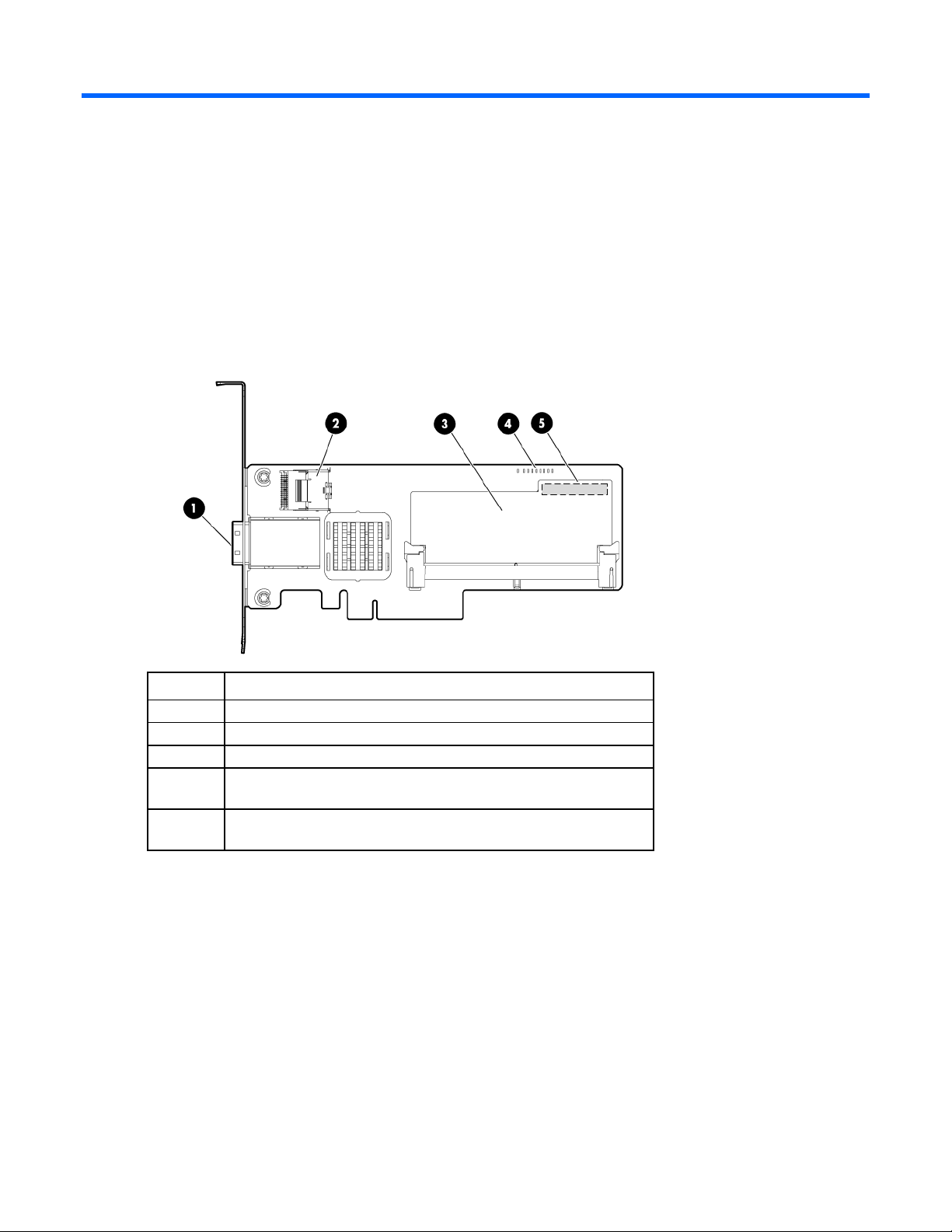
P212 components
For connector and other component locations, see the appropriate controller-specific section.
Item Description
1
2
3
4
5
Port 1E (Mini-SAS 4x connector)
Port 2I (Mini-SAS 4x connector)
Cache module (also known as array accelerator)
Status LEDs (runtime LEDs). For more information, see "Controller
board runtime LEDs (on page 16)."
(On rear of cache) Connector for the cable to an optional cache
battery that upgrades the cache to BBWC
Component identification 6
Page 7
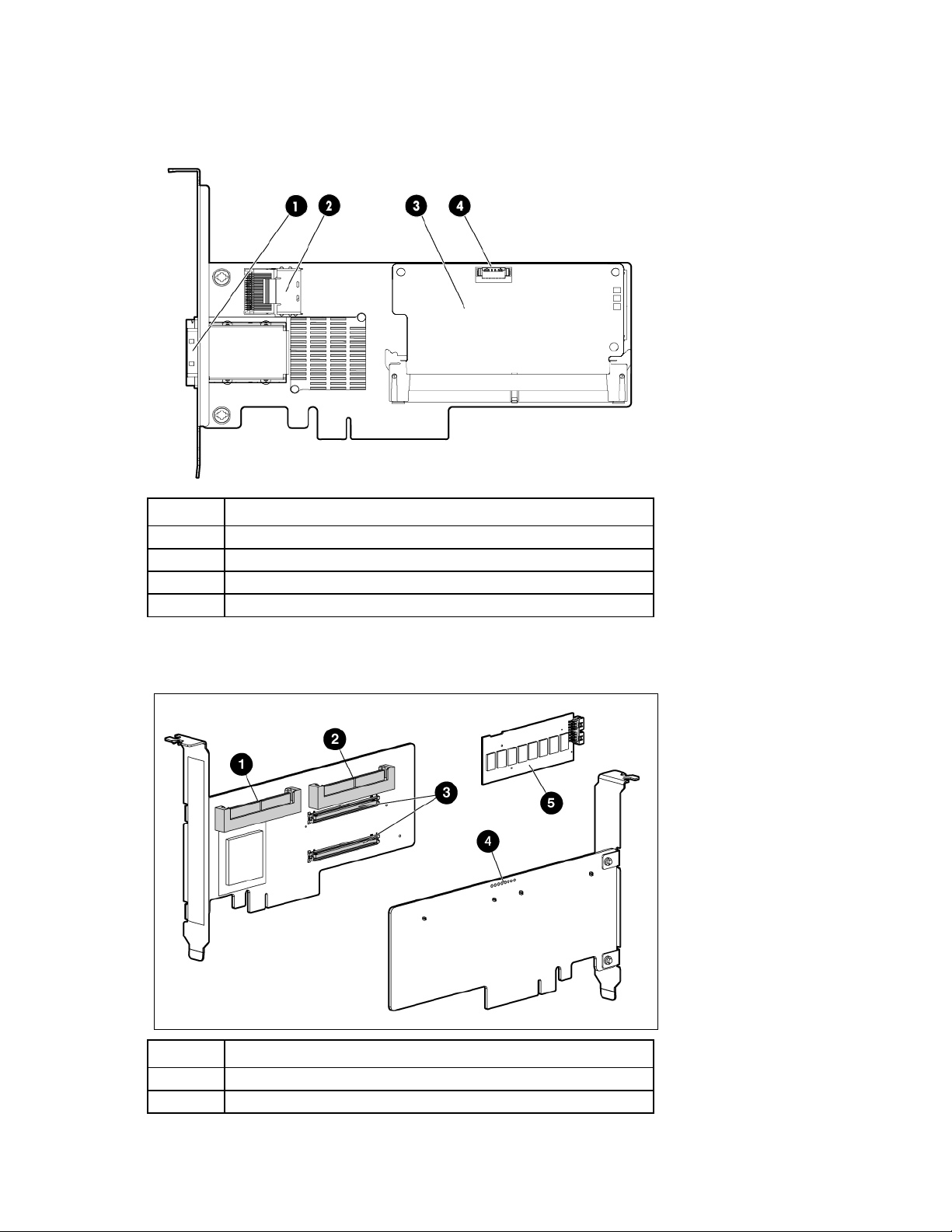
P222 components
For LED locations and status, see "P222 LEDs (on page 19)."
Item Description
1
2
3
4
Port 1E (Mini-SAS 4x connector)
Port 2I (Mini-SAS 4x connector)
Cache module (also known as array accelerator)
Capacitor pack cable connector
P400 components (model with front connectors)
Item Description
1
2
Port 2I (SAS 4x connector)
Port 1I (SAS 4x connector)
Component identification 7
Page 8
Item Description
connector for the cable to an optional battery pack that upgrades the
connector for the cable to an optional battery pack that upgrades the
3
4
5
Cache module connectors
Runtime LEDs. See "Controller board runtime LEDs (on page 16)."
Cache module (also known as array accelerator), showing the
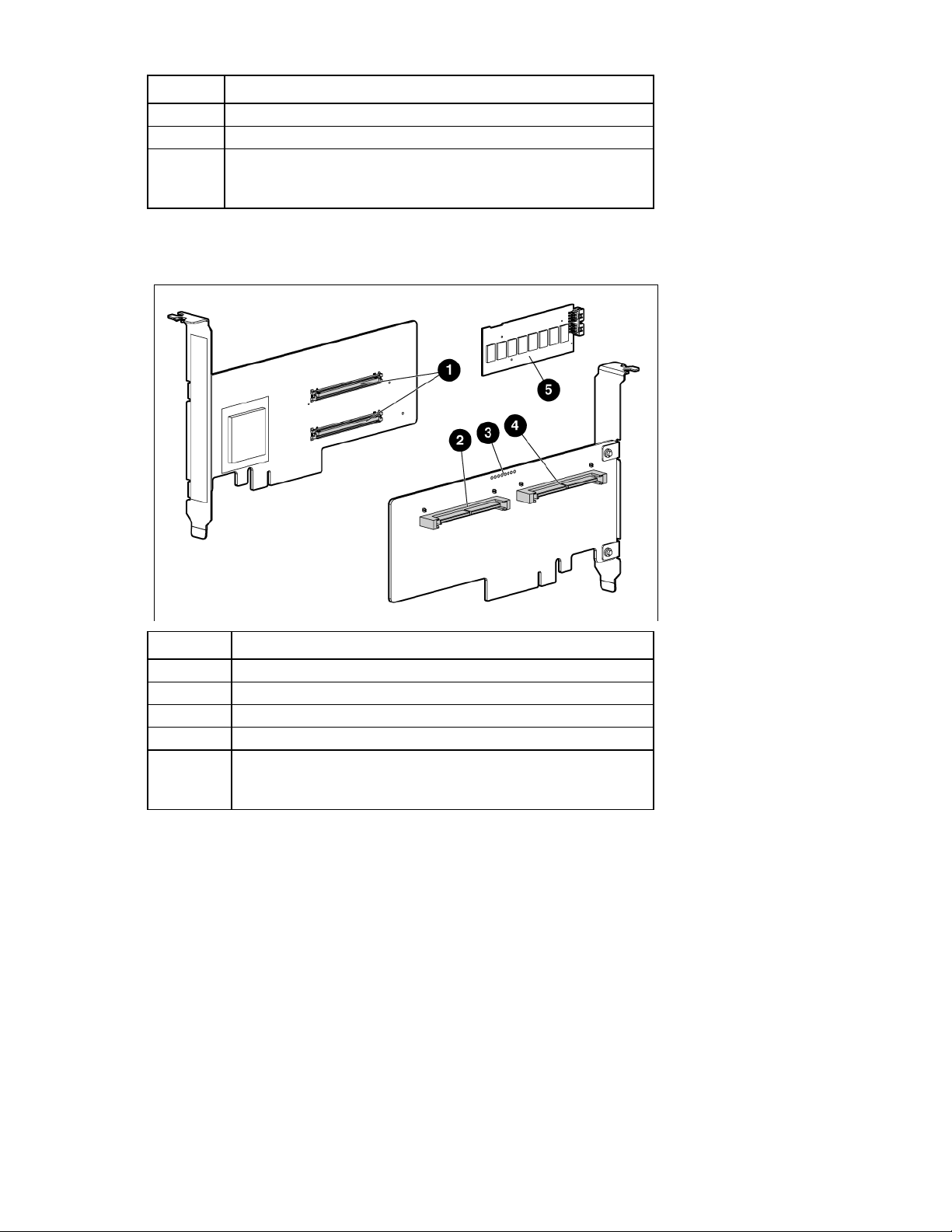
P400 components (model with back connectors)
cache to BBWC
Item Description
1
2
3
4
5
Cache module connectors
Port 1I (SAS 4x connector)
Runtime LEDs. See "Controller board runtime LEDs (on page 16)."
Port 2I (SAS 4x connector)
Cache module (also known as array accelerator), showing the
cache to BBWC
Component identification 8
Page 9
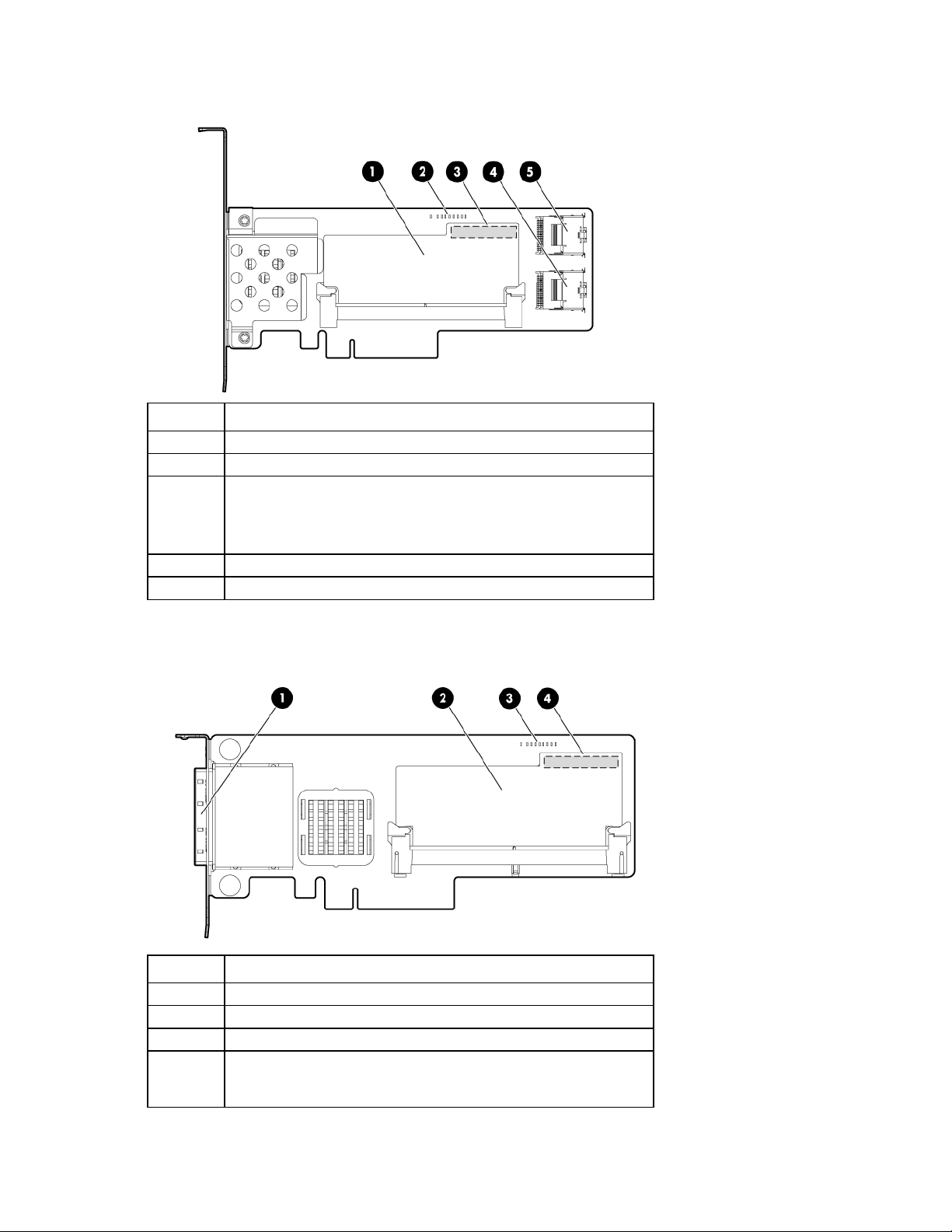
P410 components
Item Description
1
2
3
4
5
Cache module (also known as array accelerator)
Runtime LEDs. See "Controller board runtime LEDs (on page 16)."
(On rear of cache) Connector for the cable to an optional cache
battery that upgrades the cache to BBWC
(Not shown) In place of the BBWC option, the controller can support a
FBWC module and capacitor pack.
Port 1I (Mini-SAS 4x connector)
Port 2I (Mini-SAS 4x connector)
P411 components
Item Description
1
2
3
4
Ports 1E and 2E (Mini-SAS 4x connectors)
Cache module (also known as array accelerator)
Runtime LEDs. See "Controller board runtime LEDs (on page 16)."
(On rear of cache) Connector for the cable to an optional cache
battery that upgrades the cache to BBWC
(Not shown) In place of the BBWC option, the controller can support a
Component identification 9
Page 10

Item Description
FBWC module and capacitor pack.
P420 components
For LED locations and status, see "P420 LEDs (on page 19)."
Item Description
1
2
3
4
Cache module (also known as array accelerator)
Capacitor pack cable connector
Port 2I (Mini-SAS 4x connector)
Port 1I (Mini-SAS 4x connector)
Component identification 10
Page 11

P421 components
For LED locations and status, see "P421 LEDs (on page 20)."
Item Description
1
2
3
4
Port 1E (Mini-SAS 4x connector)
Port 2E (Mini-SAS 4x connector)
Cache module (also known as array accelerator)
Capacitor pack cable connector
E500 components
Item Description
1
2
Port 1E (Mini-SAS 4x connector)
Port 2E (Mini-SAS 4x connector)
Component identification 11
Page 12

Item Description
connector for the cable to an optional battery pack that upgrades the
3
Cache module (also known as array accelerator), showing the
P700m components
Item Description
cache to BBWC
1
2
3
4
5
Runtime LEDs. See "Controller board runtime LEDs (on page 16)."
Connector (not used on HP ProLiant servers)
Cache module (also known as array accelerator)
Connector for the cable to an optional cache battery that upgrades the
cache to BBWC. This connector is absent on some P700m models.
Mezzanine connector
Component identification 12
Page 13

P711m components
Item Description
1
2
3
Mezzanine connector
Runtime LED. See "Controller board runtime LEDs (on page 16)."
Cache module
P712m components
Item Description
1
2
3
4
Mezzanine connector
Runtime LED. See "Controller board runtime LEDs (on page 16)."
SAS/SATA connector
SAS/SATA connector
Component identification 13
Page 14

Item Description
5
Cache module (not available on all models)
P721m components
For LED locations and status, see "P721m LEDs (on page 23)."
Item Description
1
2
Cache module (also known as array accelerator)
Capacitor pack cable connector
P800 components
Component identification 14
Page 15

Item Description
1
2
3
4
5
6
7
Ports 1E and 2E (Mini-SAS 4x connectors)
Heartbeat LED (flashes green when operating normally and amber if
the board has failed)
Activity LED for external ports
Port 3I (Mini-SAS 4x connector)
Port 4I (Mini-SAS 4x connector)
Cache module (also known as array accelerator)
(Optional) Batteries for cache module
Two batteries are normally sufficient, but you can add a third battery to
provide extra security against loss of system power.
P812 components
Item Description
1
2
3
4
5
Ports 1E, 2E, 3E, and 4E (Mini-SAS 4x connectors)
Port 6I (Mini-SAS 4x connector)
Port 5I (Mini-SAS 4x connector)
Cache module (also known as array accelerator)
Capacitor pack for cache module
Component identification 15
Page 16

P822 components
Item Description
1
2
3
4
5
Ports 1E, 2E, 3E, and 4E (Mini-SAS 4x connectors)
Port 5I (Mini-SAS 4x connector)
Port 6I (Mini-SAS 4x connector)
Cache module
Capacitor pack connector for cache module
Controller board runtime LEDs
Immediately after you power up the server, the controller runtime LEDs illuminate briefly in a predetermined
pattern as part of the POST sequence. At all other times during server operation, the illumination pattern of
the runtime LEDs indicates the status of the controller. To determine the controller status, see the appropriate
controller-specific section.
Component identification 16
Page 17

P212, P410, and P411 LEDs
Off
25-50%
LED ID Color Name Comments
1
2
3
4
5
6
7
8
9
Gas pedal LED
status
Off
Flashing
On steadily
On steadily
Amber DS9: System Error The controller ASIC has locked up and cannot
process any commands.
Green DS8: Idle Task This LED, together with the Gas Pedal LED (next
item), indicates the amount of controller CPU
activity. For more information, see the following
table.
Green DS7: Gas Pedal This LED, together with the Idle Task LED (previous
item), indicates the amount of controller activity. For
more information, see the following table.
Green DS6: Heartbeat When the controller is in good health, this LED
flashes every two seconds.
Green DS5: Pending Command The controller is working on a command from the
host driver.
Green DS4: Port 1 Active Port 1 is active.
Green DS3: Port 2 Active Port 2 is active.
Amber DS2: Drive Failure To determine which drive has failed, check the Fault
LED of each physical drive connected to the
controller.
Amber DS1: Diagnostics Error One of the server diagnostics utilities has detected
a controller error.
Idle task LED
Controller CPU activity level
status
Flashing 0-25%
Off 50-75%
On steadily 75-100%
Component identification 17
Page 18

E500 and P400 LEDs
LED ID Color Name Comments
1
2
3
4
5
6
7
8
Amber CR14: Controller Lockup The controller ASIC has locked up and cannot process
any commands.
Amber CR13: Drive Failure To determine which drive has failed, check the Fault
LED of each physical drive connected to the controller.
Green CR3: Activity Port 2E on the E500, or port 2I on the P400, is active.
Green CR8: Activity Port 1E on the E500, or port 1I on the P400, is active.
Green CR5: Command Outstanding The controller is working on a command from the host
driver.
Green CR6: Heartbeat When the controller is in good health, this LED flashes
every two seconds.
Green CR4: Gas Pedal This LED, together with the Idle Task LED (next item),
indicates the amount of controller CPU activity. For
more information, see the following table.
Green CR7: Idle Task This LED, together with the Gas Pedal LED (previous
item), indicates the amount of controller CPU activity.
For more information, see the following table.
Gas Pedal LED status Idle Task LED status Controller CPU activity level
Off
Flashing
On steadily
On steadily
Flashing 0–25%
Off 25–50%
Off 50–75%
On steadily 75–100%
Component identification 18
Page 19

P222 LEDs
Red
Fault
When an error occurs, this LED is on. During power up, this LED
Item Color Name Interpretation
1
2
3
P420 LEDs
Green Heartbeat When the controller is in good health, this LED flashes at 1 Hz.
During power up, this LED is solid for up to 2 seconds.
is solid for up to 2 seconds.
Amber Debug On = Controller is in reset.
Off = Controller is in an idle or runtime state.
Flashing 5 Hz = Controller and cache are performing a backup.
Item Color Name Interpretation
1
Amber Debug On = Controller is in reset state.
Component identification 19
Page 20

Item Color Name Interpretation
2
3
P421 LEDs
Off = Controller is in an idle or runtime state.
Flashing 5 Hz = Controller and cache are performing a backup.
Red Fault When an error occurs, this LED is on. During power up, this LED
is solid for up to 2 seconds.
Green Heartbeat When the controller is in good health, this LED flashes at 1 Hz.
During power up, this LED is solid for up to 2 seconds.
Item Color Name Interpretation
1
2
3
Green Heartbeat When the controller is in good health, this LED flashes at 1 Hz.
During power up, this LED is solid for up to 2 seconds.
Red Fault When an error occurs, this LED is on. During power up, this LED
is solid for up to 2 seconds.
Amber Debug On = Controller is in reset.
Off = Controller is in an idle or runtime state.
Flashing 5 Hz = Controller and cache are performing a backup.
Component identification 20
Page 21

P700m LEDs
Flashing
0–25%
LED ID Color Name Comments
1
2
3
4
5
6
7
8
9
10
Amber CR10: Thermal Alert This LED is not used.
Amber CR9: System Error The controller ASIC has locked up and cannot
process any commands.
Amber CR1: Diagnostics Error One of the server diagnostics utilities has detected a
controller error.
Amber CR2: Drive Failure To determine which drive has failed, check the Fault
LED of each physical drive connected to the
controller.
Green CR3: Activity Port 2 is active.
Green CR4: Activity Port 1 is active.
Green CR5: Command Outstanding The controller is working on a command from the
host driver.
Green CR6: Controller Heartbeat When the controller is in good health, this LED
flashes every two seconds.
Green CR7: Gas Pedal This LED, together with the Idle Task LED (next item),
indicates the amount of controller CPU activity. For
more information, see the following table.
Green CR8: Idle Task This LED, together with the Gas Pedal LED (previous
item), indicates the amount of controller CPU activity.
For more information, see the following table.
Gas Pedal LED status Idle Task LED status Controller CPU activity level
Off
Flashing
On steadily
On steadily
Off 25–50%
Off 50–75%
On steadily 75–100%
Component identification 21
Page 22

P711m LED
Name: Controller heartbeat LED (CR6)
Status: Flashes every 2 seconds = The controller is functioning properly.
P712m LED
Name: Controller heartbeat LED (CR6)
Status: Flashes every 2 seconds = The controller is functioning properly.
Component identification 22
Page 23

P721m LEDs
Color Name Interpretation
Green
Amber
P800 LEDs
Heartbeat When the controller is in good health, this LED flashes at 1 Hz.
During power up, this LED is solid for up to 2 seconds.
Fault When an error occurs, this LED is on. During power up, this LED
is solid for up to 2 seconds.
Component identification 23
Page 24

Green
CR504: Gas Pedal
This LED, together with the Idle Task LED (next item),
Flashing
0–25%
LED ID Color Name Comments
1
2
3
4
5
6
7
8
9
10
Green CR502: Expander Heartbeat This LED flashes every two seconds during normal
operation. If the LED glows steadily, the expander
cannot function due to an internal problem. If the
LED flashes twice per second, the expander cannot
function because the NVRAM is corrupt.
Amber CR510: System Error The controller ASIC has locked up and cannot
process any commands.
Amber CR509: Diagnostics Error One of the server diagnostics utilities has detected
a controller error.
Amber CR500: Drive Failure To determine which drive has failed, check the Fault
LED of each physical drive connected to the
controller.
Green CR508: Activity Port 4I is active.
Green CR507: Activity Port 3I is active.
Green CR506: Command Outstanding The controller is working on a command from the
host driver.
Green CR505: Controller Heartbeat When the controller is in good health, this LED
flashes every two seconds.
indicates the amount of controller CPU activity. For
more information, see the following table.
Green CR503: Idle Task This LED, together with the Gas Pedal LED (previous
item), indicates the amount of controller CPU
activity. For more information, see the following
table.
Gas pedal LED status Idle task LED status Controller CPU activity level
Off
Flashing
On steadily
On steadily
Off 25–50%
Off 50–75%
On steadily 75–100%
Component identification 24
Page 25

P812 LEDs
Item Color Name Comments
1
2
3
4
5
6
7
8
Green CR76: Idle Task This LED, together with the Gas Pedal LED
(following item), indicates the amount of controller
CPU activity. For more information, see the
following table.
Green CR75: Gas Pedal This LED, together with the Idle Task LED (previous
item), indicates the amount of controller CPU
activity. For more information, see the following
table.
Green CR74: Heartbeat When the controller is in good health, this LED
flashes every 2 seconds.
Green CR73: Pending Command The controller is working on a command from the
host driver.
Green CR72: Port 1 Activity Port 1 is active.
Green CR 71: Port 2 Activity Port 2 is active.
Amber CR78: Drive Failure To determine which drive has failed, check the Fault
LED of each physical drive connected to the
controller.
Amber CR77: Diagnostics Error One of the server diagnostics utilities has detected
a controller error.
9
Green CR82: MIPS ready The embedded SAS expander is active.
Gas pedal LED status Idle task LED status Controller CPU activity level
Off
Flashing
On
On
Flashing 0–25%
Off 25–50%
Off 50–75%
On 75–100%
Component identification 25
Page 26

P822 LEDs
Red
Fault
When an error occurs, this LED is on. During power up, this LED
Item Color Name Interpretation
1
2
3
Green Heartbeat When the controller is in good health, this LED flashes at 1 Hz.
During power up, this LED is solid for up to 2 seconds.
is solid for up to 2 seconds.
Amber Debug On = Controller is in reset.
Off = Controller is in an idle or runtime state.
Flashing 5 Hz = Controller and cache are performing a backup.
FBWC module LEDs
FBWC module LEDs (P410, P411, P711m, P812)
The FBWC module has two single-color LEDs (green and amber). The LEDs are duplicated on the reverse side
of the cache module to facilitate status viewing.
Component identification 26
Page 27

•
•
1 Green LED 2 Amber LED Interpretation
Off
Flashing (1 Hz)
Flashing (1 Hz)
On
Flashing (2 Hz)
Alternating with
amber LED
On
Off
On A backup is in progress.
On A restore is in progress.
Off The capacitor pack is charging.
Off The capacitor pack has completed charging.
Flashing (2 Hz)
Alternating with
green LED
One of the following conditions exists:
The charging process has timed out.
The capacitor pack is not connected.
On The flash code image failed to load.
Off The flash code is corrupt.
FBWC module LEDs (P222, P420, P421, P721m, P822)
The FBWC module has three single-color LEDs (one amber and two green). The LEDs are duplicated on the
reverse side of the cache module to facilitate status viewing.
1 - Amber 2 - Green 3 - Green Interpretation
Off
Off
Off
Off
Off
Off
Off
Off
Flashing 1 Hz
Flashing 1 Hz
Off Off The cache module is not powered.
Flashing 0.5 Hz Flashing 0.5 Hz The cache microcontroller is executing from within its
boot loader and receiving new flash code from the host
controller.
Flashing 1 Hz Flashing 1 Hz The cache module is powering up, and the capacitor
pack is charging.
Off Flashing 1 Hz The cache module is idle, and the capacitor pack is
charging.
Off On The cache module is idle, and the capacitor pack is
charged.
On On The cache module is idle, the capacitor pack is charged,
and the cache contains data that has not yet been
written to the drives.
Flashing 1 Hz Off A backup is in progress.
On Off The current backup is complete with no errors.
Flashing 1 Hz Off The current backup failed, and data has been lost.
Flashing 1 Hz On A power error occurred during the previous or current
boot. Data may be corrupt.
Component identification 27
Page 28

1 - Amber 2 - Green 3 - Green Interpretation
Flashing 1 Hz
Flashing 2 Hz
Flashing 2 Hz
On
On
On Off An overtemperature condition exists.
Flashing 2 Hz Off The capacitor pack is not attached.
Flashing 2 Hz On The capacitor has been charging for 10 minutes, but
On Off The current backup is complete, but power fluctuations
On On The cache module microcontroller has failed.
Battery pack LEDs
has not reached sufficient charge to perform a full
backup.
occurred during the backup.
Item Color Description
1
2
3
4
Green System Power LED. This LED is on when the system is
powered up and 12 V system power is available. This
power supply is used to maintain the battery charge and
provide supplementary power to the cache microcontroller.
Green Auxiliary Power LED. This LED is on when 3.3V auxiliary
voltage is detected. The auxiliary voltage is used to
preserve BBWC data and is available any time that the
system power cords are connected to a power supply.
Amber Battery Health LED. To interpret the illumination patterns of
this LED, see the following table.
Green BBWC Status LED. To interpret the illumination patterns of
this LED, see the following table.
Component identification 28
Page 29

power is available, as indicated by LED 2. In the absence of auxiliary
pack. BBWC features are disabled until the battery pack is replaced.
pack. BBWC features are disabled until the battery pack is replaced.
LED3 pattern LED4 pattern Interpretation
Off
Off
Off
Off
Off
Flashing (1 Hz)
On
Flashing (2 Hz) The system is powered down, and the cache contains data that has not
yet been written to the drives. Restore system power as soon as
possible to prevent data loss.
Data preservation time is extended any time that 3.3 V auxiliary
power, battery power alone preserves the data. A fully-charged
battery can normally preserve data for at least 2 days.
The battery lifetime also depends on the cache module size. For more
information, see the controller QuickSpecs on the HP website
(http://www.hp.com).
Double flash, then
pause
The cache microcontroller is waiting for the host controller to
communicate.
Flashing (1 Hz) The battery pack is below the minimum charge level and is being
charged. Features that require a battery (such as write cache, capacity
expansion, stripe size migration, and RAID migration) are unavailable
temporarily until charging is complete. The recharge process takes
between 15 minutes and 2 hours, depending on the initial capacity of
the battery.
On The battery pack is fully charged, and posted write data is stored in the
cache.
Off The battery pack is fully charged, and no posted write data exists in
the cache.
Flashing (1 Hz) An alternating green and amber flashing pattern indicates that the
cache microcontroller is executing from within its boot loader and
receiving new flash code from the host controller.
— A short circuit exists across the battery terminals or within the battery
Flashing (1 Hz)
The life expectancy of a battery pack is typically more than 3 years.
— An open circuit exists across the battery terminals or within the battery
The life expectancy of a battery pack is typically more than 3 years.
Component identification 29
 Loading...