

Page 1
Agilent
4291B RF
Impedance/Material
Analyzer
F
or
additional
CO
VERED
SERVICE MANU
This
number
important
BY
THIS
manual
MANU
SERIAL
applies
prex
JP1KE,
information
AL" in
NUMBERS
directly
to
or
rmware
about
instruments
serial
General Information
AL
with
revision
numbers,
of
serial
01.00.
read \ANAL
this
service
YZERS
manual.
Agilent Part No. 04291-90111
Printed in JAPAN March 2001
Page 2

Notice
The
information
This
document
reserved.
language
contains
No
part
without
contained
proprietary
of
this
the
prior
in
this
document
written
document
information
may
be
consent
is
subject
that
is
photocopied,
of
the
Agilent
to
change
protected
without
by
copyright.
reproduced,
T
echnologies Company
notice
or
translated
.
All
.
rights
to
another
are
Agilent
T
echnologies
Component
1-3-2,
Hyogo
Murotani,
,
651-2241
T
est
Japan,
PGU-Kobe
Nishi-ku,
Japan
Ltd.
Kobe-shi,
c
Copyright 1998, 2000, 2001 Agilent Technologies Japan, Ltd.
Page 3
Manual Printing
The
manual
changes
at
reprint
technical
printing
when
do
not
changes
a
date
new
edition
cause
are
incorporated.
History
and part
is
printed. (Minor
the
date to
number indicate
corrections and
change.)
The manual
its current
part number
edition. The
updates that
changes when
printing date
are incorporated
extensive
January
May
1998
June
2000
March
1998
2001
:
:
::
::
::
::
:
:
:
:
:
:
:
:
:
:
:
:
:
:
:
:
:
::
::
::
::
:
:
:
:
:
:
:
:
:
:
:
:
:
:
:
:
:
::
::
::
::
:
:
:
:
:
:
:
:
:
:
:
First
Edition
:
:
:
:
::
::
::
:
:
:
:
:
:
:
:
:
:
:
:
:
:
:
:
:
:
:
::
::
::
:
:
:
:
:
:
:
Second
:
:
:
:
::
::
::
:
:
:
:
:
:
:
:
:
:
:
:
:
:
:
:
:
:
:
::
::
::
:
:
:
:
:
:
:
:
:
:
:
:
::
::
::
::
:
:
:
:
:
:
:
:
:
:
:
:
:
:
:
:
:
::
::
::
::
:
:
:
F
Third
ourth
Edition
Edition
Edition
(part
(part
(part
number:
number:
number:
04291-90111)
04291-90111)
04291-90111)
iii
Page 4
Safety Summary
The
following
service
W
ARNINGS
and
intended
The
A
gilent
with
these
,
general
and
repair
given
use
T
echnologies Company
safety
of
this
elsewhere
of
the
requirements
precautions must
instrument. F
in
this
instrument.
.
be observed
ailure to
comply with
manual violates
assumes no
liability for
during all
these precautions
safety standards
the customer's
phases of
of design,
failure
operation,
or with
specic
manufacture,
to
comply
Note
Note
Ground
This
safety earth
terminals,
cord set.
is
a
The
Safety
ground
power
Whenever
made inoperative
DO NOT
Do
not operate
electrical
Keep
Operate
instrument in
Away
From Live
4291B
in
LEDs
CLASS
comply
IEC1010-1.
in 4291B
1
LED
Instrument
Class 1
the
product (provided
must
be
source
and
to
it
is
secured
In
the
likely
An
instrument
such an
with
INST
4291B
are
are
Class
PRODUCT
provided
product
that
the
against
Explosive
in
the
presence
environment
Circuits
ALLA
TION
INDOOR
1
in
accordance
with a
from
the
input
wiring
protection
any
unintended
Atmosphere
constitutes
CA
TEGORY
USE
product.
with
protective earth
main
power
terminals
has
been
operation.
of
ammable
a
safety
II
and
IEC825-1.
terminal).
source
,
power
to
impaired,
gasses
or
hazard.
POLLUTION
An
the
product
cord,
or
supplied
the
product
fumes
.
Operation
DEGREE
2
uninterruptible
input
wiring
power
must
be
of
any
Operating
adjustments
with
with
circuits before
DO NOT Service Or A
the
the
personnel
must
power
power
cable
cable
touching them.
must
be
made
connected.
removed.
not
remove
by
qualied
Under
T
o
avoid
djust Alone
instrument
maintenance
certain
injuries
covers
conditions
,
always
Do not attempt internal service or adjustment unless
aid and resuscitation, is present.
iv
.
Component
personnel.
,
dangerous
disconnect
Do
not
power
replacement
replace
voltages
components
may
and
discharge
and
exist
internal
even
another person, capable of rendering rst
Page 5
DO
NOT
Substitute
P
arts
Or
Modify
Instrument
Because
unauthorized
Sales
Dangerous
W
arnings
this
W
arning
of
the
modications
and
Service
Procedure W
,
such as
manual. Instructions
danger
Oce
the
of
for
example
Dangerous
instrument.
this
instrument.
introducing
to
the
instrument.
service
and
arnings
below
contained in
voltages
Use
extreme
additional
repair
,
precede
the
warnings
,
capable
caution
hazards
Return
to ensure
potentially
must
of
causing
when
,
do
not substitute
the
instrument
the safety
dangerous
be
death,
handling,
features are
followed.
are
parts or
to a
Agilent T
procedures
present in
testing,
perform
echnologies
maintained.
throughout
this
and
adjusting
v
Page 6
Typeface Conventions
Bold
Italics
Computer
4
HARDKEYS
N
NN
NN
NN
NN
N
N
N
N
N
N
N
N
N
N
N
SOFTKEYS
Safety
General
5
N
N
N
N
N
N
Symbols
denitions
Instruction
necessary
Alternating
Boldface
symbols
Italic
publications
Italic
must
be
lename
type
the
Computer
Labeled
Softkeys located
of
safety
symbols
manual
for
current.
.
type
type
the
type
is
.
is
typed
means
name
font
keys
symbol:
user
is
used
also
in
of
is
on
used
to
used
for
used
place
to
type
a
le
used
the
instrument
to the
on
the
refer
when
a
term
emphasis
for
keyboard
of
the
words
the
word
such
as
for
on-screen
right of
equipment
product
to
the
instruction
is
and
copy
file1
front
the
or in
is
marked
dened.
for
titles of
entries
in
italics
,
to
type a
.
prompts
panel
LCD
are
manuals are
with
manual.
F
or example:
manuals and
when
a
.
F
or
example:
space,
and
messages.
are
enclosed in
enclosed
this
icons
other
name
or
a
copy
and then
5
4
N
NN
NN
.
in
listed below
symbol
when it
are
variable
to
.
.
is
Direct
On
O
In
Out
Frame
equipment
This
condition or the like
result in injury or death to
This
condition or the like
result in damage to or destruction of part or
This
procedure, practice, condition or the like
current.
(Supply).
(Supply).
position of
position
(or
chassis)
which normally
Warning
Caution
Note
sigh denotes important information. It calls attention to a
push-button switch.
of
push-button
terminal. A
sign
denotes
, which,
switch.
connection to
include all
a
hazard.
exposed metal
It
if not correctly performed or adhered to
personnel.
sign denotes a hazard. It calls
, which, if not
correctly performed or adhered to
the frame
(chassis) of
the
structures.
calls
attention
to
a
procedure
, practice
,could
attention to a procedure
, practice
,could
all of the product.
, which is essential to highlight.
Axed to product containing static sensitive devices use anti-static handling
procedures to prevent electrostatic discharge damage to component.
,
,
vi
Page 7
Certication
Agilent
at
calibration
T
echnology
facilities
W
This
T
echnologies
the
time
of
measurements
,
of
arranty
Agilent
workmanship
certain
specied
either
F
or
Agilent
T
echnologies
pay
another
Agilent
T
echnologies
property
of
components
repair
warranty
Technologies
all
shipping
country
T
the
instrument,
period.
echnologies
installed
shipment
to
the
extent
other
International
T
echnologies
for
a
During
or
replace
service
shall
pay
charges
.
for
use
on
or
Company
from
period
listed
the warranty
products
or
repair
. Buyer
shipping
,
duties
warrants
with
that
software
certies that
the factory
are
traceable
allowed by
. Agilent
to
the Institution's
Standards Organization
instrument
of
one
in
General
product
year
from the
Information
period, Agilent
that prove
,
this
product
shall prepay
charges
,
and
that
an
instrument
instrument.
,
or
rmware
taxes
its
software
Agilent
shipping
to
will
this product
Technologies
the
United States
is
warranted against
date of
of
to be
defective
must
be
returned to
charges
return
for
the
products
and
rmware
execute
T
echnologies
will
be
uninterrupted
met its
published specications
further certies
National Institute
calibration facility
members.
defects in
shipment, except
this manual,
Technologies
the warranty
Company will,
.
a
service
to
product
returned
Agilent
to
Buyer
to
Agilent
T
designated
its
programming
does
not
warrant
or
error
that its
of Standards
,or
to the
material and
that in
facility
echnologies
.
However
T
echnologies
by
Agilent
instruction
that
free
.
calibration
the
case
shall
be
at
its
designated
and
Agilent
,
Buyer
when
the
operation
and
of
for
the
option,
by
shall
from
Limitation
The
foregoing
maintenance
misuse
,
preparation
No
other
implied
by
operation
or
warranty
warranties
Of
W
arranty
warranty
Buyer
shall
,
Buyer-supplied
outside
maintenance
is
expressed
of
merchantability
not
apply
the
environmental
.
or
to
software
implied.
and
defects
resulting
or
interfacing,
specications
A
gilent
tness
from
unauthorized
for
the
T
echnologies
for
a
particular purpose
improper
product,
specically
or
inadequate
modication
or
improper
disclaims
.
or
site
the
vii
Page 8
Exclusive Remedies
The
remedies
shall
not
whether
be
liable
based
provided
for
on
contract,
herein
any
direct, indirect,
Assistance
are buyer's
tort,
or
sole and
special, incidental,
any other
exclusive remedies
legal theory
or consequential
.
.A
gilent T
echnologies
damages,
Product
Agilent
F
or
A
ddresses
Documentation
The
maintenance
T
echnologies
any
assistance
are
following
Quick
The
to
Start
Quick
make
measurement
agreements
products
,
contact
provided
Map
manuals
are available
Guide(Agilent
Start
Guide
basic
measurements
examples
Operation Manual(Agilent
The
Operation Manual
softkeys
features
Programming
The
.It
also
provides
.
Manual
Programming
Manual
your
at
the
walks
.
describes
(Agilent
and
other
.
nearest Agilent
back
of this
for the
P
art
Number 04291-90031)
you through
,
explains
P
art
Number
all
information
P
art
provides
customer
Technologies
manual.
analyzer:
system setup
commonly
04291-90030)
function
on
option
Number
information
assistance
Sales and
and
used
features
accessed
and
from
accessories
04291-90027)
on
GPIB
agreements
Service Oce
initial
the
,
and
front
power-on,
typical
panel
available
programming.
are
available
application
keys
and
the
.
shows
and
analyzer
for
how
HP
Instrument
The
HP
programming
provides
B
ASIC
Programming
B
ASIC
Instrument
language
a
general
B
programming
Instrument BASIC Language R
Service Manual (Option 0B
The
Service Manual
repair the instrument.
APC-7
is a U.S. registered trademark of the Bunker Ramo Corporation.
R
viii
Users
ASIC
Handbook,
Users
,
provides
Handbook
some
reference
T
echniques
,
HP
eference
W only), (Agilent P
(Agilent
introduces
helpful
hints
.
It
is
Instrument
.
art Number 04291-90111)
P
art
Number
you
on
getting
divided into
BASIC
explains how to do performance tests
E2083-90005)
to
the HP
the
three books
Interface
Instrument B
most use
,
HP
T
echniques
ASIC
from it,
Instrument
,
and
and
HP
, and to adjust, troubleshoot, and
Page 9
Contents
1.
General
INTRODUCTION
ORGANIZATION
ANALYZERS
TABLE
2.
P
erformance
INTRODUCTION
GENERAL
W
Ambient Conditions
Calibration
P
Recommended
FREQUENCY
Description
Specication
T
Procedure
OSC
Description
Specication
T
Procedure
MEASUREMENT
Description
Specication
T
Procedure
DC
Description .
Specication...... .....
Test Equipment .. ...... ...... ...... ...... .... 2-17
Procedure . . . . . . . . . . . . . . . . . . . . . . . . . . . . . . . . . 2-17
PERFORMANCE TEST RECORD ....................... 2-20
Frequency Accuracy Test........ ...... ..... ...... . 2-20
Osc Level Accuracy Test .......................... 2-20
Information
.
.
.
.
.
.
.
.
.
.
.
.
.
.
.
.
.
.
..
..
..
.
.
.
.
OF
SERVICE
CO
VERED
OF
SERVICE
T
INFORMA
arm
Up
Time
Cycle
erformance
A
est
Equipment
.
LEVEL
est
est Equipment
Save
Analyzer
Open Measurement T
Short Measurement T
50 Measurement T
10 cm Airline with Open T
10
BIAS LEVEL A
Without Option 1D5 .......... ...... ..... ...... 2-20
WithOption1D5..... ...... ..... ...... ...... . 2-20
A
CCURA
Equipment
.
..
the Analyzer
Calibration
cm Airline with Short T
TEST
ests
.
.
.
TION
.
.
.
..
.
.
T
est
Record
T
est
Equipment
CCURA
.
.
.
.
.
.
.
.
CY
.
.
.
.
.
.
.
.
.
.
.
.
.
.
.
CY
.
.
.
.
.
.
.
.
.
.
.
.
.
.
.
A
CCURA
.
.
.
.
.
.
.
.
..
..
..
..
Setup .
CCURACY TEST (OPTION 001)
...... ...... ...... ...... .
MANU
BY
MANU
EQUIPMENT
.
.
.
.
.
.
.
.
.
..
.
.
.
.
.
TEST
.
.
.
.
.
.
.
.
.
.
.
.
TEST
.
.
.
.
.
.
.
..
..
..
CY
TEST
.
..
.
..
.
.
.
.
.
.
.
.
est ..........
est ...................
est...................
est..................
AL
.
.
.
.
.
.
.
.
.
.
.
.
AL
.
.
.
.
.
.
.
.
.
.
.
.
..
.
.
.
.
.
.
.
.
.
.
.
.
.
.
.
.
.
.
.
..
..
..
..
.
.
.
.
.
.
.
.
.
.
.
.
.
..
..
.
.
.
.
.
.
.
.
.
.
.
.
.
..
.
.
.
.
.
.
.
.
.
.
.
.
.
.
.
.
.
.
.
.
.
.
.
.
.
.
.
..
..
..
.
.
.
.
.
.
.
.
.
.
..
..
..
.
.
.
.
.
.
.
.
.
.
.
.
.
.
.
.
.
.
.
.
.
.
.
.
.
.
.
.
.
..
.
.
.
.
.
.
.
.
.
.
..
..
.
.
.
.
.
.
..
.
.
.
.
.
.
.
.
.
.
.
.
.
.
..
.
.
.
.
.
.
.
.
.
.
.
.
.
.
..
.
.
.
.
.
.
.
.
.
.
.
.
.
.
.
.
.
.
.
..
.
.
.
.
.
.
.
.
.
.
.
..
.
.
.
.
.
.
.
.
.
.
.
.
.
.
..
..
.
.
.
.
.
.
..
.
.
.
.
.
.
.
.
.
.
.
.
.
.
.
.
.
.
.
.
.
.
.
.
.
.
.
.
.
..
..
..
..
.
.
.
.
.
.
..
..
.
.
.
.
.
.
.
.
.
.
.
.
..
..
.
.
.
.
.
.
.
.
.
.
.
.
.
.
.
.
.
.
.
.
.
.
.
.
.
.
.
..
.
.
.
.
.
.
.
.
.
.
.
.
.
.
..
..
..
..
.
.
.
.
.
.
.
.
.
.
.
.
.
.
.
..
.
.
.
.
.
.
.
.
.
.
..
...............
est...................
...... ...... ...
.....................
.
..
..
..
..
.
..
..
.
.
.
.
.
.
.
.
.
.
.
.
.
.
.
.
.
.
..
.
.
.
.
.
..
.
.
.
..
..
.
..
.
.
.
.
.
.
.
.
.
.
.
.
.
.
.
.
.
.
.
.
.
.
.
.
.
.
.
.
.
.
.
.
.
.
.
.
.
.
.
.
.
.
.
.
.
.
.
.
.
.
.
.
.
.
.
.
.
.
.
.
.
.
.
..
..
..
..
..
..
..
.
.
.
......
.......
.....
....
......
.
.
..
..
..
.
.
.
.
.
.
..
.
.
.
.
.
.
.
.
.
.
.
.
.
.
.
.
.
.
.
.
.
.
.
.
.
..
.
.
.
.
.
.
..
.
..
.
.
.
1-1
. 1-1
.
1-3
. 1-4
.
2-1
.
2-1
.
2-1
. 2-1
.
2-1
.
2-1
.
2-2
.
2-3
.
2-3
.
2-3
.
2-3
.
2-3
.
2-5
.
2-5
.
2-5
. 2-5
2-5
.
2-8
. 2-8
. 2-8
.
2-8
.
2-8
. 2-8
.
2-11
2-12
2-12
2-13
2-13
2-15
2-17
2-17
2-17
Contents-1
Page 10
Norm-T
Norm-T
High-T
High-T
Measurement
Norm-T
Norm-T
High-T
High-T
DC
3.
A
djustments
INTRODUCTION
SAFETY
REQUIRED
W
ARM-UP
INSTRUMENT
ORDER
UPD
A
A
djustments
Keyboard
Controller
Updating
40
MHz
Required
Procedure
520
MHz
Required Equipment
Procedure
COMB
Required
Procedure
STEP
Required
Procedure
SECOND
Required
Procedure
SOURCE
Required
Procedure . . . . . . . . .
THIRD LOCAL V
Required Equipment . . . . . . . . . .
Procedure . . . . . . . . . . . . . . . . . . . . .
SOURCE MIXER LOCAL LEAKA
Required Equipment . . . . . . . . . . . . . . . . . . . . .
Procedure . . . . . . . . . . . . . . . . . . . . . . .
OSC LEVEL CORRECTION CONST
Required Equipment . . . . . . . . . . . . . . . . . . . . . . . . . . . . 3-20
Procedure . . . . . . . . . . . . . . . . . . . . . . . . . . . . . . . . . 3-20
HOLDSTEPADJUSTMENT..... ...... ...... ...... ... 3-21
Required Equipment . . . . . . . . . . . . . . . . . . . . . . . . . . . . 3-21
Procedure . . . . . . . . . . . . . . . . . . . . . . . . . . . . . . . . . 3-21
BAND PASS FILTER ADJUSTMENT . . . . . . . . . . . . . . . . . . . . . . 3-22
Required Equipment . . . . . . . . . . . . . . . . . . . . . . . . . . . . 3-22
emp High-Impedance
emp Low-Impedance
emp High-Impedance
emp Low-Impedance
Accuracy
emp High-Impedance
emp
Low-Impedance
emp
High-Impedance
emp
Low-Impedance
Bias
A
ccuracy
and
Correction
.
.
CONSIDERA
EQUIPMENT
FOR
ADJUSTMENTS
CO
VER
OF
ADJUSTMENTS
TING
Correction
Program
and
Mouse
Requirement
Correction
REFERENCE
Equipment
.
.
.
.
LEVEL
GENERATOR
PRETUNE
LOCAL
V
CXO
ADJUSTMENT
..
.
.
Equipment .
..
..
CORRECTION
Equipment
.
.
.
.
PLL
Equipment
.
.
.
.
ADJUSTMENT
Equipment
CXO ADJUSTMENT
Test
T
T
est
T
est
T
est
.
T
T
T
est
T
est
T
est
.
.
.
.
Constants
.
.
.
.
.
.
TIONS
REMO
Constants
Constants
OSCILLA
.
.
.
.
ADJUSTMENT
.
.
.
LOCK
.
.
.
.
.
.
.
AND
V
AL
.
.
.
.
.
Operation
.
.
.
TOR
.
.
..
.
..
.
.
.
.
.
.
.
.
.
..
.
.
.
.
.
.
CONST
.
.
.
.
.
.
.
.
ADJUSTMENT
.
.
.
.
.
.
.
.
.
.
.
.
GE ADJUSTMENT . . . . . . . . . . . . . . .
.
.
.
USING
.
.
.
.
.
.
.
...... ...... ...... ......
Head .
est
Head
Head
Head
.
.
.
.
est
Head
est
Head
Head
Head
.
.
.
.
.
.
.
.
.
.
.
.
.
CORRECTION
.
.
..
.
.
.
THE
.
.
.
.
.
.
.
.
.
.
.
.
..
FREQUENCY ADJUSTMENT
..
.
.
.
.
.
.
.
.
..
.
.
.
.
.
.
.
.
.
.
.
.
.
.
.
.
ANTS
.
.
.
.
.
.
.
.
.
.
.
.
.
.
.
.
.
..
.
.
......
ANTS....................
.
.
.
.
.
.
.
.
.
.
.
..
(Option
(Option
(Option
.
.
.
(Option
(Option
(Option
.
.
..
.
.
.
.
.
.
..
.
..
.
.
.
.
.
.
.
..
.
.
.
.
.
.
.
.
.
.
.
.
.
.
.
.
.
.
.
.
.
.
.
.
.
.
.
.
.
.
..
..
.
.
..................
012)
.
.
.
.
.
.
013)
014)
.
.
.
.
013)
014)
..
..
..
.
..
..
..
..
ADJUSTMENTS
.
.
.
.
..
.
.
.
.
.
.
.
.
.
.
.
.
.
.
.
.
.
.
.
.
.
.
.
.
..
.
.
.
.
.
..
..
.
.
.
.
.
.
.
.
.
.
.
.
.
.
.
.
.
..
..
..
..
.
.
.
.
.
.
.
..
012)
.
.
.
.
.
.
.
.
.
.
.
.
.
.
.
.
.
.
.
..
..
.
.
.
.
.
..
.
.
.
.
.
.
..
..
..
.
.
..
..
..
.
.
.
CONST
..
.
.
..
..
.
.
.
.
.
.
.
.
.
.
.
.
.
.
...... ..... ....
ANTS
.
.
.
.
.
.
.
.
.
.
.
..
..
..
..
.
.
.
.
.
.
.
.
.
.
.
.
.
.
.
.
.
.
.
.
.
.
.
.
.
.
.
.
.
.
.
.
.
.
.
.
.
.
.
.
..
..
..
..
.
.
.
.
.
.
..
..
..
..
..
.
.
.
.
...... ......
.
.
.
.
.
.
.
.
.
.
PROGRAM
.
.
.
.
.
.
.
.
.
.
.
.
.
.
..
.
.
.
.
.
.
.
.
.
.
.
.
.
.
.
.
.
.
..
.
.
.
.
.
.
.
.
.
.
..
.
.
.
.
..
..
.
.
.
.
.
.
.
.
..
..
..
.
.
..
.
.
..
.
.
...... .
...... ....
..
..
.
..
..
..
..
..
.
..
.
.
.
.
.
.
.
.
.
.
.
.
.
.
.
.
.
.
.
.
.
.
.
.
.
.
.
.
.
.
.
..
.
.
.
.
.
.
..
.
..
.
.
.
.
.
..
..
.
.
.
.
.
.
..
..
..
..
..
..
..
..
..
.
.
.
.
.
.
.
.
..
.
.
.
.
.
.
.
.
.
.
.
.
.
.
.
.
.
.
.
.
.
.
.
.
.
.
.
..
.
.
..
.
.
.
.
..
.
.
.
.
.
.
.
.
..
..
..
..
..
..
.
.
.
.
..
.
.
.
.
.
.
.
.
.
..
.
.
.
.
..
.
.
.
.
.
.
.
2-20
2-21
2-21
. 2-22
.
2-23
2-23
2-31
2-39
. 2-47
.
2-55
.
3-1
.
3-1
.
3-2
3-2
.
3-2
.
3-2
.
3-3
.
3-3
.
3-3
.
3-4
.
3-5
.
3-6
.
3-6
3-6
.
3-8
.
3-8
.
3-8
.
3-10
3-10
.
3-10
.
3-13
.
3-13
.
3-13
. 3-14
.
3-14
.
3-14
.
3-16
.
3-16
3-16
3-17
3-17
3-17
3-18
3-18
3-18
3-20
Contents-2
Page 11
Procedure
DC
BIAS LEVEL
Procedure
10
MHz REFERENCE
ONL
Y) .
Required
Procedure
4.
Overall
TROUBLESHOOTING
INSPECT
Check
Check
Check
VERIFY
Source
Receiver
Transducer
INSPECT
Check the
Check
Check
Troubleshooting
THE
the
the
Error
Troubleshooting
A2
POST
FUNCTIONAL
T
est
T
est
Equipment
Procedure
T
est
Equipment
Procedure
T
est
Equipment
Procedure
THE
the P
the mini
..
..
..
CORRECTION
..
.
.
.
OSCILLA
.
.
.
.
.
Equipment .
.
.
.
.
.
SUMMARY
POWER
F
an
.
.
.
Front
P
anel
Message
When
REGULA
.
.
.
.
.
.
.
.
.
T
est
.
.
.
.
.
.
.
.
T
est
.
.
.
.
.
.
.
REAR
GPIB
arallel
P
Interface
Interface
DIN
.
.
.
.
.
.
.
.
.
.
.
.
.
.
.
.
.
.
ON
SEQUENCE
.
.
.
.
LEDs
.
.
.
.
P
ower
TOR
T
est
GROUPS
.
.
.
..
.
.
.
.
.
.
.
.
.
.
.
.
.
.
.
.
..
..
..
..
.
..
..
.
.
..
ANEL
Keyboard
FUNCTION
.
.
.
.
CONST
.
.
.
TOR
FREQUENCY
.
.
.
.
.
.
.
.
.
.
.
.
..
.
.
.
.
.
.
On
F
ail
.
.
.
..
.
.
.
.
.
.
.
..
.
.
.
.
.
.
.
.
.
.
.
.
.
.
.
.
.
.
.
.
Connector
.
.
.
ANTS
.
..
.
..
.
.
.
.
..
.
.
.
.
.
..
..
.
.
.
.
.
..
Self-test
.
.
.
.
.
.
.
.
.
.
.
.
.
.
.
..
..
..
..
.
.
.
.
.
.
.
.
.
.
.
.
.
.
.
.
.
.
.
.
.
..
(OPTION
..
..
ADJUSTMENT
..
..
.
.
.
.
..
..
.
.
.
.
.
.
.
.
.
.
.
..
..
..
..
F
ailed
..
..
..
..
.
.
.
.
.
.
..
.
.
.
.
.
.
.
..
..
.
.
.
.
.
.
.
.
.
.
.
.
.
.
.
.
..
.
.
.
.
.
.
.
.
.
.
.
.
.
.
..
001
..
..
..
..
.
.
.
.
.
.
..
..
.
.
..
..
.
.
.
.
.
.
.
.
.
.
.
.
.
.
.
.
.
.
.
.
.
.
.
.
.
..
ONL
..
..
..
.
.
.
.
.
.
.
..
.
.
.
..
..
.
.
.
.
.
.
.
.
.
.
.
.
.
.
.
.
.
.
.
.
.
.
.
.
.
..
..
.
.
.
.
..
.
.
.
.
.
.
.
.
.
.
..
Y)
..
(OPTION
.
..
.
.
..
.
..
.
.
.
.
.
.
..
.
.
.
.
.
.
.
.
.
.
.
.
.
.
.
.
.
.
.
.
.
.
.
.
.
.
.
.
.
.
..
.
.
..
.
.
.
..
..
.
.
.
.
.
.
.
.
.
.
.
.
.
.
.
.
.
.
.
.
.
.
.
.
.
..
.
.
.
.
.
.
..
.
.
..
..
.
.
.
.
.
.
..
.
.
.
.
.
.
.
.
.
.
.
.
.
.
.
.
.
.
.
.
.
.
.
.
.
.
.
.
.
.
..
..
.
.
1D5
.
.
..
.
.
.
.
.
.
.
.
.
.
..
.
.
.
.
.
.
.
.
.
.
.
.
.
.
.
..
.
..
.
.
.
.
.
.
..
.
..
.
.
.
.
..
.
.
.
.
.
.
.
.
.
.
.
.
.
.
.
.
.
.
.
.
.
.
.
.
.
.
.
.
.
.
.
.
.
.
. 4-9
. 4-10
..
.
. 4-10
.
.
.
.
.
.
.
3-22
3-24
3-24
3-25
3-25
3-25
4-2
4-4
4-4
4-4
4-5
4-5
4-6
4-7
4-7
4-7
4-7
4-9
4-9
4-10
4-12
4-12
4-12
4-12
5.
Power
INTRODUCTION
ST
FIND OUT WHY THE F
FIND OUT WHY THE A50 SHUTDOWN LED IS OFF
FIND OUT WHY THE A1 +5 VD LED IS NOT ON STEADILY .......... 5-11
Supply Troubleshooting
.
.
.
.
.
.
.
.
.
.
.
.
.
.
.
.
.
..
..
.
.
.
.
.
.
.
.
.
ART
HERE
1.
Check
2.
Check
3.
Check
A50
SHUTDOWN
4.
Check
Measure
5. Check the Eight A2 LEDs
6. Run Internal T
1. Check the Line V
2. Check the A50 SHUTDOWN LED . . . . . . . . . . . . . . . .
1. Disconnect the Cable from the A50J1
2. Disconnect the Cable from the A51J2
3. Disconnect the Cable from A22J1 (Option 001 Only) . . . . . . . . . . . . 5-9
4. Disconnect the Cable from the A1J10 ... ..... ...... .... 5-9
5. Remove Assemblies . . . . . . . . . . . . . . . . . . . . . . . . . . . 5-10
1. Check the A40 Pre-regulator . . . . . . . . . . . . . . . . . . . . . . . 5-11
2. Check the A50 DC-DC Converter . . . . . . . . . . . . . . . . . . . . . 5-11
3. Disconnect Cables on the A1 CPU .................... 5-12
.
Error
the
the
the
the
.
.
.
.
.
.
.
.
.
.
.
.
..
..
..
..
.
.
.
.
Messages
F
an
is
A50
SHUTDOWN
A1
+5
A1
+5
est 4: A2 POST REGULA
.
.
.
.
.
.
.
.
.
.
.
.
.
.
..
..
..
Rotating
LED
VD
VD
AN IS NOT ROT
oltage, Selector Switch Setting, and Fuse . . . . . . . . .
.
LED
V
oltage
.
.
LED
.
.
.
.
..
....
.
.
.
.
.
.
.
.
.
..
..
..
.
.
.
.
.
.
.
.
.
.
.
.
..
.
.
.
..
..
..
..
.
.
.
.
..
..
..
..
..
.
.
.
.
..
.
.
.
.
.
.
.
.
.
.
.
..
....................
TOR .
ATING .
.... ...... ...... .
.... ...... ...... ..
...............
................
...... ...... ..
.
.
.
.
.
.
.
.
..
..
.
.
.
.
.
.
.
.
.
.....
.
.
.
.
.
.
.
.
.
.
.
.
..
.
.
.
.
.
.
.
5-1
.
5-3
.
5-3
.
5-3
.
5-3
.
5-4
.
5-5
.
5-5
5-5
5-6
5-8
5-8
5-8
5-9
. 5-9
5-9
Contents-3
Page 12
4.
Remove Assemblies
TROUBLESHOOT
1.
Troubleshoot the
2.
Troubleshoot the
TROUBLESHOOT
1.
Check the
2.
Check
3.
Remove
4.
Measure
6.
Digital
INTRODUCTION
ST
ART
1.
Check
Check
Check
2.
Check
Identify
3.
Check
4.
Check
5.
Check
6.
Check
7.
Check
TROUBLESHOOT
1.
Run
2.
Check
the
Control
HERE
the
the
the
Error
the
the
the
the
the
the
the
THE F
AN
F
an
A50
THE A2
A40
Pre-Regulator
A50
DC-DC
Assemblies
the
A2
P
ost
Troubleshooting
.
.
.
.
.
.
.
.
P
ower
On
5
and
4
Ch
1
A1
Eight
LEDs
Messages
the
First
F
ailed
A1
DRAM
A1
V
olatile
A30
Front
A53
FDD
A32
I-B
ASIC Interface
THE
A51
Internal
A52
T
est 3:
LCD(Liquid
..
..
.
.
AND
THE
.
.
.
.
.
DC-DC
POST-REGULA
Converter
.
.
Regulator
.
.
.
.
Sequence
4
Ch
.
and
Memory
Keyboard
.
.
GSP
Converter
.
.
.
.
.
.
.
.
..
5
Operations
2
.
.
.
.
.
T
est
.
Flash
.
.
.
and
A51 GSP
Crystal
.
.
Output
.
.
.
..
.
Memory
.
.
A52 LCD
.
.
.
A50
DC-DC
.
.
.
TOR
.
.
.
.
.
.
.
.
.
V
.
..
..
..
.
.
.
.
.
.
.
..
.
..
.
.
.
.
.
.
..
..
and the
.
.
Display)
.
.
.
CONVERTER
.
..
.
.
.
.
.
.
.
.
.
.
.
.
..
oltages
..
..
..
.
..
.
.
.
.
..
..
..
..
.
.
.
.
.
.
.
.
..
..
mini
..
.
.
.
..
.
.
..
.
.
.
.
.
.
.
.
..
.
.
.
.
..
.
.
..
.
.
.
.
.
.
.
..
..
DIN
.
.
.
.
.
.
..
..
..
.
.
.
.
.
.
.
.
..
..
..
..
.
.
.
.
.
.
.
.
.
.
..
..
.
.
.
.
..
..
.
.
.
.
.
.
.
.
.
.
.
.
.
.
.
..
.
.
.
Keyboard
.
.
.
.
.
.
.
.
.
.
..
..
.
.
.
.
..
..
..
.
.
.
.
.
.
..
.
.
.
.
..
.
.
.
.
.
.
.
.
.
.
..
.
.
..
.
..
.
.
..
..
.
.
..
.
.
.
.
.
.
..
.
.
.
.
.
.
.
.
.
.
.
.
.
.
.
.
.
.
.
.
..
.
.
..
..
..
..
.
.
.
..
.
.
.
.
.
.
..
.
.
.
.
.
.
.
.
.
.
.
.
.
.
.
.
.
.
.
.
.
.
..
.
..
.
..
..
..
.
.
.
.
..
.
.
.
.
.
.
..
.
.
.
.
.
.
.
.
.
.
.
.
.
.
.
.
.
.
.
.
.
.
..
. 5-14
.
.
. 5-15
..
. 5-17
.
.
.
.
.
.
.
.
.
.
.
.
.
.
.
.
.
.
.
.
.
.
.
.
.
.
.
.
.
.
.
.
.
.
.
5-13
5-14
5-17
5-17
5-17
5-17
6-1
6-3
6-3
6-3
6-3
6-4
6-4
6-5
6-6
6-6
6-6
6-7
6-8
6-8
6-8
7. Source
INTRODUCTION
SOURCE
ST
CHECK A5 SYNTHESIZER OUTPUTS
CHECK A4A1 1ST LO OUTPUTS
CHECK AN A3A1 SOURCE VERNIER OUTPUT ................ 7-21
CHECK A3A2 2ND LO OUTPUTS . . . . . . . . . . . . . . . . . . . . . . . 7-23
CHECK A3A3 SOURCE OUTPUT .. ...... ..... ...... .... 7-27
Troubleshooting
..
.
.
.
.
.
.
.
.
.
.
.
.
.
.
.
.
.
.
.
.
.
.
.
..
.
.
.
GROUP TROUBLESHOOTING
Start
Here .
Check
Check
Check
Check
Check
Check
Check
Check
ART
1. Check the INT REF Signal . . . . .
2. Check the FRA
3. Check the STEP OSC Signal
4. Check the 520 MHz Signal . . . . . . . . . . . . . . . .
5. Check the EXT REF Operation . . . . . . . . . . . . . . . . .
1. Check the 1st LO OSC Signal at A4A1J3
2. Check the 1st LO OSC Signal at A4A1J4 ................. 7-19
1. Check the 21.42 MHz Signal . . . . . . . . . . . . . . . . . . . . . . . 7-21
1. Check the 2nd Local Oscillator Signal .................. 7-23
2. Check the 2.05858 GHz Signal . . . . . . . . . . . . . . . . . . . . . . 7-24
A5 Synthesizer
A4A1
an
A3A2
A3A3
A7
A22
A60
HERE
..
1st
A3A1
2nd
Source
Output
DC
High
.
.
.
.
.
.
.
.
Outputs .
LO
Outputs
Source
Bias
Stability
.
V
LO
Outputs
Output
Attenuator
1/2
Output
.
.
..
C N OSC Signal . . . .
.
ernier
.
.
Control
Frequency
.
.
.
SUMMARY
.
.
.
.
.
.
.
.
.
.
.
.
.
.
.
.
.
Output
.
.
.
.
...... ...... ....
...... ...... ...... .
.
.
.
.
.
.
.
.
.
.
.
.
Signals
.
.
.
..
Reference
.
.
.
.
.
......
...... ...... ...... .
..................
.
.
.
.
.
.
.
.
.
.
.
.
.
.
.
.
.
.
..
..
.
.
.
.
.
.
.
.
.
.
.
.
.
.
.
.
.
.
..
..
.
.
.
.
.
.
.
.
.
..
..
..
.
.
.
.
.
.
..
..
..
.
.
.
.
.
.
.
..
..
..
.
.
.
.
.
.
.
.
.
.
.
..
..
..
.
.
.
.
.
.
(Option
.
.
................
1D5)
..
..
..
.
.
.
.
.
.
.
.
...............
...... .
........
.
.
.
.
.
.
.
.
.
.
.
.
.
.
.
.
..
.
.
.
.
.
.
.
.
.
..
..
.
.
.
.
..
..
.
.
..
.....
....
.
7-1
.
7-3
.
7-3
. 7-3
.
7-3
.
7-3
.
7-3
.
7-3
7-4
.
7-4
. 7-4
.
7-5
7-6
7-6
7-8
7-10
7-13
7-15
7-17
. 7-17
Contents-4
Page 13
1.
CHECK
1.
CHECK
1.
CHECK
8.
Receiver
INTRODUCTION
RECEIVER
ST
ART
T
est
Procedure
9.
Transducer
INTRODUCTION
TRANSDUCER
ST
ART
T
est
Procedure
10.
Service
INTRODUCTION
SERVICE
N
N
N
NN
TESTS
N
N
N
N
N
SERVICE
N
N
N
N
N
READ
N
N
N
N
N
FIRMWARE
TESTS
N
N
N
NN
EXECUTE
N
NN
N
N
INTERNAL
N
N
N
N
N
EXTERNAL
N
N
N
N
N
ADJUSTMENT
N
N
NN
NN
DISPLAY TESTS
Test Status
Diagnostic T
Test Descriptions . . . . . . . . . . . . . . . . . . . . .
Check the
A7 OUTPUT
Check A7
A22 DC
Check A22
THE A60
HERE
Equipment
FRONT
HERE
Equipment
CABLE
High
K
N
N
N
N
N
N
N
N
N
N
N
N
N
N
N
N
N
N
N
N
N
N
N
N
N
N
N
N
N
N
N
N
N
N
N
N
N
N
ID
N
N
N
N
N
N
N
NN
NN
N
N
MENU
NN
N
N
N
N
N
N
N
N
N
N
N
N
N
N
N
N
N
N
N
N
N
N
N
N
N
N
N
N
N
N
N
N
N
N
N
NN
N
N
N
N
N
NN
NN
NN
NN
NN
NN
NN
NN
N
N
N
N
NNNNNNNNNNNNNNNNNNN
INTERNAL TESTS
0: ALL INT
1: A1 CPU
2: A1 V
3: A51 GSP
4: A2 POST REGULATOR ........................ 10-9
5: A6 A/D CONVERTER .......... ...... ...... ... 10-9
6: A5 REFERENCE OSC ......................... 10-9
7: A5 FRACTIONAL N OSC . . . . . . . . . . . . . . . . . . . . . . . . 10-9
8: A5 STEP OSC . . . . . . . . . . . . . . . . . . . . . . . . . . . . . 10-9
9: A4A1 1ST LO OSC .......................... 10-10
10:A3A22NDLOOSC.......................... 10-10
A3A3 RF
Control
BIAS
Output
HIGH
Troubleshooting
.
GROUP
.
.
.
.
.
ISOL'N
Troubleshooting
.
GROUP
.
.
.
.
.
ISOL'N
T
emperature
ey
Menus
.
MENU
.
N
N
N
N
N
NN
N
N
N
N
N
N
N
N
N
N
N
N
N
N
N
NN
NN
NN
NN
N
N
N
N
N
N
N
N
N
N
N
.
.
.
.
NN
N
N
N
N
N
N
N
N
N
N
N
N
N
N
N
N
MODES
.
.
.
N
N
N
N
N
N
N
N
N
N
N
N
N
N
NN
NN
N
N
REVISION
.
.
N
N
N
N
N
NN
NN
N
N
N
N
N
N
TEST
(
NN
NN
N
N
N
N
N
N
N
N
N
N
N
N
NNNNNNNNNNNNNNNNNNNNNNNNN
OLATILE MEMORY . . . . . . . . . . . . . . .
:DIAG:TEST:EXET
N
N
N
N
N
N
N
N
N
N
N
N
N
N
N
TESTS
N
N
N
N
N
N
N
N
N
N
N
N
N
N
NN
TESTS
N
N
N
N
N
N
N
N
NN
NN
NN
NN
TESTS
NN
NN
NN
NN
NN
NN
N
N
..........
ests ....................
...... ...... ....
.................
...................
Signal .
A
TTENU
Signals
1/2
OUTPUT
V
oltages
ST
ABILITY
.
.
.
.
TROUBLESHOOTING
.
.
.
.
.
.
.
.
.
.
.
.
T
est
F
ailure
.
.
.
.
TROUBLESHOOTING
.
.
.
.
.
.
.
.
.
.
.
.
T
est F
ailure Troubleshooting
T
est
Head Trouble
.
.
.
.
.
.
.
.
.
.
.
.
(
:DIAG:SERV:MODE
.
.
.
N
N
N
N
(
.
N
N
N
N
N
N
N
N
N
(
:DIAG:FREV?
.
.
.
..
(
:DIAG:TEST
(
:DIAG:TEST
N
N
N
N
N
N
(
:DIAG:TEST
:DIAG:TEST
...... ...
.
.
.
A
TOR
CONTROL
.
.
.
.
.
.
.
.
FREQUENCY
.
.
.
.
.
.
.
.
.
.
.
.
.
.
.
..
.
.
.
.
..
Troubleshooting
.
.
..
..
.
.
.
.
.
.
.
.
.
.
.
.
.
.
..
.
..
.
.
.
.
.
.
.
.
.
.
.
.
.
.
.
.
.
)
..
.
.
)
0
)
17
)
34
)
40
)
......................
.
.
.
.
.
.
.
.
SIGNALS
.
.
.
.
.
..
..
.
.
.
.
.
.
.
.
.
.
.
.
.
.
.
.
..
REFERENCE
.
.
.
.
.
..
..
SUMMARY
.
.
..
..
..
..
..
..
..
..
SUMMARY
.
.
..
.
.
.
.
.
..
..
.
Isolation (Opt.
.
.
.
.
.
.
.
.
.
.
.
.
.
.
{ON|1}
..
.
.
.
.
..
)
.
.
.
.
.
.
..
.
.
.
.
.
.
.
.
.
.
.
.
.
.
.
.
..
..
..
..
...... ...... ...... .
.
.
..
.
.
.
.
..
.
.
.
.
.
.
.
.
.
.
.
.
.
.
.
.
.
.
.
.
.
.
..
..
.
.
.
.
.
.
.
.
.
.
.
.
.
.
.
.
.
.
.
.
.
..
.
.
.
.
.
.
.
.
.
.
.
.
.
.
..
..
..
..
.
.
.
...............
...... ..... ...
..
..
..
..
.
.
.
.
.
..
..
..
..
..
..
..
..
..
..
..
.
.
.
.
..
.
.
.
.
.
.
.
.
.
.
.
.
.
.
.
.
.
.
.
.
.
.
.
.
.
.
.
.
.
.
.
.
.
.
..
..
..
.
.
.
.
.
.
.
.
.
.
.
.
.
..
.
.
.
.
.
.
.
.
.
.
.
.
.
.
.
.
.
.
.
.
.
.
.
.
.
.
.
.
013
and
014)
.
.
.
.
.
.
.
.
.
.
.
..
.
.
.
.
..
.
.
.
.
.
.
.
.
.
.
.
.
.
.
.
.
.
.
.
.
.
.
.
.
.
.
.
.
.
.
.
.
.
.
.
.
.
.
.
.
.
..
..
..
..
.
.
.
.
.
.
.
.
.
.
.
.
.
.
.
.
..........
.........
...... ...
......
......
..
..
..
..
..
.
.
.
.
.
.
.
.
.
.
.
.
..
.
.
..
.
.
.
.
.
.
.
.
.
.
.
.
.
.
.
.
.
.
.
.
.
.
.
.
.
..
..
.
.
.
.
.
..
..
..
..
..
.
.
.
.
.
.
.
.
.
.
.
.
.
.
.
.
.
.
.
.
.
.
.
.
.
.
.
..
.
.
.
..
.
.
..
.
.
.
.
.
.
.
.
..
.
..
.
.
.
..
7-27
. 7-29
.
7-29
7-31
.
7-31
. 7-33
.
8-1
8-3
.
8-4
.
8-4
.
8-4
.
8-5
.
9-1
.
9-4
.
9-5
.
9-5
.
9-5
.
9-6
.
9-7
.
10-1
.
10-3
.
10-3
10-3
.
10-3
.
10-4
10-5
10-5
.
10-5
.
10-6
.
10-6
10-6
10-6
10-7
10-8
10-8
10-8
10-8
10-8
10-9
Contents-5
Page 14
11:
A3A1 DIVIDER
12:
A6 3RD
13:
A3A1 SOURCE
14:
A6 SEQUENCER
15:
SOURCE LEVEL
16:
DC BIAS
N
NN
N
N
N
N
N
N
N
N
N
N
N
N
EXTERNAL
17:
FRONT P
18:
DSK
19:
POWER SWEEP
20:
SOURCE FLA
21:
OUTPUT A
22:
RECEIVER GAIN
23:
A6 GAIN
24:
A6 V/I
25:
FRONT ISOL'N
26:
TRD LOSS
27:
CABLE
28:
TRD
29:
TRD
30:
HIGH
31:
LOW
32:
HIGH
33:
HIGH
N
N
N
N
N
N
N
N
NN
NN
N
N
N
ADJUSTMENT
34:
HOLD
35:
BPF
36:
3RD
37:
2ND
38:
SOURCE
39:
SOURCE
N
N
N
N
N
N
N
N
N
N
N
N
N
N
N
DISPLAY
40:
TEST
41:
TEST
42:
TEST
43:
TEST
44:
TEST P
SERVICE
N
N
N
NN
BUS
N
NN
NN
CORRECTION
NNNNNNNNNNNNNNNNN
SYNTH
NNNNNNNNNNN
OSC
N
NNNNNNNNNNNNNNNNNNNNNN
DC BIAS
NNNNNNNNNNN
TRD
NNNN
IF
Service Modes . .
BUSMEASUREMENTMENU..... ...... ...... ...... .. 10-17
NNNNNNNNNNNNNNNNNNNNNNNNNNNNNNNNNNNNNNNNNNNNNNN
BUS MEAS on OFF(:DIAG:SERV:BUS:STAT {ON|OFF}
NNNNNNNNNNNNNNNNNNNNNNNNNNNNNNNNNNNNNN
DC BUS [OFF](:DIAG:SERV:BUS:DC<numeric>) ....... ...... 10-17
NNNNNNNNNNNNNNNNNNNNNNNNNNNNNNNNNNNNNNNNNNNN
FREQ BUS [OFF](:DIAG:SERV:BUS:FREQ<numeric>) ........... 10-17
NNNNNNNNNNNNNNNNNNNNNNNNNNNNNNNNNNNNNNNNNNNNNNNNNN
AZ SWITCH on OFF(:DIAG:SERV:BUS:AZER {OFF|ON|0|1}
MODES MENU
NN
NN
NN
N
N
N
N
N
N
N
N
N
N
MEAS [OFF]
NN
NN
N
N
N
N
N
N
N
N
N
N
N
NN
...
......
NNNN
....................
LO
NN
NN
NN
NN
NN
NN
NN
N
N
N
N
N
N
N
N
N
TESTS
ANEL DIA
DR
FA
TTENUA
NORMALIZER
ISOLA
ISOL'N
ISOL'N
Z HEAD
Z HEAD
TEMP
TEMP
N
N
N
N
N
N
N
N
N
N
N
N
N
N
N
N
N
N
NN
NN
N
TESTS
STEP
ADJ
V
CXO
LO
PLL
MIXER
V
N
N
N
N
N
NN
N
N
N
N
N
N
NN
NN
NN
..............
CXO
NN
N
N
N
N
N
N
N
N
N
N
N
N
N
N
TESTS
P
A
TTERN
P
A
TTERN
P
A
TTERN
P
A
TTERN
ATTERN
N
NN
NN
NN
NN
N
N
N
N
N
N
N
NN
NN
NN
N
N
N
N
N
N
N
N
N
CONSTANTS
.........................
...... ...... ....
..
..
.
.
.
.
.
.
.
.
.
.
.
..
..
..
OSC
.
.
.
.
.
.
.
.
.
..
..
..
..
..
..
OSC
.
.
N
N
NN
NN
.
ULT
TNESS .
..
.
.
.
TION
ITO
V
TO
..
HIGH
LOW
N
N
N
N
N
N
N
N
N
N
N
ADJ
.
.
.
LEVEL
LOCK
N
N
N
N
N
N
.
N
..
N
N
NN
NN
NN
NN
NN
...... ...... ...... ...... .
...... ..... ...... ...... ..
.
.
.
.
.
.
.
.
.
.
.
.
.
.
.
.
.
.
.
.
.
.
.
.
G. .
ISOL'N .
LINEARITY .
TOR .
..
.
.
.
V
I
..
Z HEAD
Z HEAD
N
.
.
ADJ
LEAK
LEVEL
.
1
2 .
3
4
5 .
..
..
NN
NN
N
N
N
..
.
.
.
.
.
.
.
.
.
..
..
.
..
.
.
.
.
ADJ
.
.
.
..
..
.
..
.
..
.
..
..
.
..
..
.
.
..
.
.
.
.
.
.
.
.
.
.
.
.
.
.
.
..
..
.
.
.
.
.
.
ADJ
ADJ
.
.
..
..
..
..
.
.
.
..
.
.
.
.
.
.
.
.
.
.
..
..
..
..
..
.
.
.
.
.
.
.
.
..
..
..
..
.
.
.
.
.
.
.
.
..
..
..
..
.
.
.
.
.
..
..
..
..
..
..
.
.
.
.
.
.
..
..
..
..
.
.
.
.
.
.
.
.
.
.
.
.
.
.
.
.
.
.
.
.
.
.
.
.
.
.
.
.
.
.
.
.
.
.
.
.
.
.
.
.
.
.
.
.
.
.
.
.
.
.
.
.
.
.
.
.
.
.
.
.
.
.
.
.
.
.
.
.
.
.
.
.
.
.
.
.
.
.
.
.
.
.
.
.
.
.
.
.
.
.
.
.
.
.
.
.
.
.
.
.
.
.
.
.
.
.
.
.
..
..
.
.
.
.
.
.
.
.
.
.
.
.
.
.
..
.
.
.
.
.
.
.
.
.
.
.
..
..
..
.
.
.
.
.
.
.
.
.
..
..
..
..
.
.
.
.
.
.
.
.
.
.
.
.
.
.
.
..
.
.
.
.
.
.
.
.
.
.
.
.
.
.
.
.
.
.
.
.
.
.
.
.
.
.
.
.
.
.
.
.
.
.
.
.
.
.
.
.
.
.
.
.
.
.
.
.
.
.
.
.
.
.
.
.
.
.
.
.
.
.
.
.
..
.
.
.
.
.
.
.
.
.
.
.
.
.
.
..
.
.
.
.
.
.
.
.
.
.
.
.
.
.
.
.
.
.
.
.
.
.
.
.
.
.
.
.
.
.
.
.
.
.
.
.
.
.
.
.
.
.
.
..
.
.
.
.
.
.
.
.
.
.
.
..
.
.
.
.
.
.
.
.
.
.
.
.
.
.
.
.
.
.
.
.
.
.
.
.
.
.
.
.
..
.
.
.
.
.
.
.
.
.
.
.
.
.
.
.
.
..
.
.
.
.
.
.
.
.
.
.
.
.
..
..
.
.
.
.
.
.
.
.
.
..
..
.
.
.
.
.
.
.
.
.
.
.
.
.
.
.
.
.
.
.
..
.
.
.
.
.
.
.
.
.
.
.
.
.
..
.
.
.
.
.
.
.
.
.
.
.
.
.
..
.
.
.
.
.
.
.
.
.
.
.
.
.
.
.
.
.
.
.
.
.
.
.
.
.
.
.
..
.
.
.
.
.
.
.
.
.
.
.
.
.
.
.
.
.
.
.
.
.
.
.
.
.
.
.
..
..
.
.
.
.
.
.
.
.
.
.
..
.
.
.
.
....................
...... .
...... ...... .....
................
)............ 10-17
)..... .... 10-18
..
..
..
..
..
.
.
.
.
.
.
.
.
.
.
..
.
..
.
..
..
..
..
.
..
.
.
.
.
.
..
.
..
.
.
.
.
.
.
.
.
.
.
..
.
.
.
.
.
.
.
.
.
.
.
.
.
.
.
.
..
..
..
.
.
..
..
.
.
.
.
..
.
..
.
.
..
.
.
.
.
.
.
.
.
.
.
..
..
..
..
.
.
.
. 10-11
..
. 10-11
..
. 10-11
..
. 10-11
..
.
..
..
.
.
.
.
.
.
.
.
.
.
.
..
.
.
.
.
.
..
. 10-12
..
. 10-12
.
.
.
.
.
.
.
.
.
.
.
.
.
.
.
.
.
.
.
.
.
.
.
.
.
.
.
.
.
.
.
.
.
.
.
.
.
.
.
.
.
.
.
.
.
.
..
.
.
.
.
.
.
.
.
..
..
..
..
..
..
.
.
.
.
....
....
10-10
10-10
10-10
10-10
10-10
10-10
10-10
10-10
10-10
10-11
10-11
10-11
10-11
10-12
10-12
10-12
10-12
10-12
10-13
10-13
10-13
10-13
10-13
10-13
10-13
10-13
10-13
10-13
10-13
10-14
10-14
10-15
10-15
10-15
10-15
10-15
10-16
10-16
10-16
10-16
Contents-6
Page 15
N
N
N
N
N
N
N
N
N
N
NN
NN
NN
NN
NN
NN
NN
N
N
N
N
N
N
N
Node
V
15
12.6
5
V
V
AN
A
C
V
V
V
VTUNE
INTEG
VREF
BIAS
BIAS
N
(
:DIAG:SERV:BUS:WAIT
..
.
.
alues .
Descriptions
.
.
.
.
(A
UX)
(2.025
(
0
1.92
U)
V
(
0
2.124
(
0
2.025
U)
(2.025
V
V
V
POWER
V
VTUNE
LO
OUT
LO
OUT
LO
VTUNE
LO
LO
Bus Node
.
OSC
NNNNNNNNNNNNNNNNNNNNNNNNN
U)
(2.1465
(1.8955
(A
UX)
(1.92
(2.002
(2.0605
LEVEL
VTUNE
VTUNE
VTUNE
LEVEL
.
OSC
U)
U)
(1.92
U)
U)
.
U)
(Source
VTUNE
(Detector
(Level
(Step
(Fractional N
OUT (Fractional
(Reference
(A/D
V
OL
T
A
CURRENT
.
.
.
Descriptions
.
.
.
(Source
OUT
(Divider
(Step
Oscillator)
(Reference Oscillator)
(Third Local Oscillator)
ANTS MENU
NNNNN
(
:DIAG:SERV:CCON:OLEV {NORM|FRON|OFF}
.............................. 10-30
.
.
.
.
.
.
U)
.
.
.
.
U)
.
.
.
.
.
.
.
.
.
.
.
.
.
.
.
U)
.
.
.
.
.
.
.
.
.
.
.
.
.
.
Oscillator
(Second
Output)
.
.
.
D
A
C
Output V
(First
Oscillator
(Third
.
..
Converter
GE
.
.
.
.
.
.
.
.
.
.
.
.
.
.
.
Oscillator)
...... ...... ...... ..... ..
(
:DIAG:SERV:CCON:DCB {OFF|ON|0|1}
<
numeric
.
.
.
.
.
..
.
.
.
.
.
.
.
.
.
.
.
.
.
.
.
.
..
.
.
.
.
.
.
.
.
.
.
.
.
.
.
.
.
.
.
..
.
.
.
.
.
.
.
.
.
.
.
.
.
.
.
.
.
.
.
.
.
..
..
.
.
..
..
.
..
..
.
.
.
.
.
V
CO
Local
Oscillator
.
.
..
..
..
oltage) .
Local
Oscillator
V
CO
Oscillator
N
Oscillator
Oscillator V
Local Oscillator
.
.
.
.
.
V
oltage
.
.
.
.
.
.
.
.
.
.
Output)
Reference)
.
.
.
.
.
.
.
.
.
.
.
.
.
.
.
.
..
.
.
.
.
.
...... ...... ...... ..
..
...... ...... ...... ..
>
)
..
..
..
..
..
..
.
.
.
.
..
..
..
..
..
..
..
.
.
.
.
.
.
.
.
..
..
..
..
..
.
.
.
.
.
.
.
..
..
..
..
..
.
.
.
.
..
..
..
..
..
..
.
..
..
..
..
..
..
.
.
.
.
.
.
.
.
..
..
..
..
.
.
.
.
.
.
.
.
..
..
..
.
.
.
.
.
.
.
.
.
.
.
.
..
..
..
.
.
.
.
.
.
.
.
..
..
.
.
.
.
.
.
.
.
.
.
.
.
.
..
..
..
.
.
.
.
.
.
.
.
.
.
.
.
..
..
..
..
.
.
.
.
.
.
.
.
.
..
..
..
..
.
.
.
.
.
.
.
.
.
..
..
..
..
.
.
.
.
.
.
.
.
..
..
.
.
.
.
.
.
.
.
.
.
.
.
.
..
..
.
.
.
.
.
.
.
.
.
.
.
.
..
..
.
.
.
.
.
.
.
.
.
.
.
.
.
..
..
.
.
.
.
.
.
.
.
.
.
.
.
.
Tuning
..
..
Turning
V
CO
CO
.
.
.
.
.
.
.
.
.
.
.
.
..
.
.
.
.
.
.
..................
V
V
CO
..
..
.
.
.
.
V
CO
Turning V
V
Turning
Integrator
Tuning
V
CO
Tuning
.
.
.
.
.
.
.
.
.
.
.
.
.
.
.
.
.
.
..
..
.
.
.
.
.
.
.
..
oltage)
Tuning
.
.
oltage) .
V
.
.
.
.
.
.
.
.
.
.
.
.
.
.
.
.
.
V
oltage)
.
.
.
.
.
.
.
.
.
.
.
.
.
.
.
oltage) .
..
V
oltage)
Output
oltage)
V
oltage)
.
.
.
.
.
.
.
.
.
.
.
..
..
.
.
.
.
.
.
.
..
..
.
..
..
.
.
.
.
.
.
.
.
.
.
.
.
..
..
..
..
..
.
.
.
.
.
). . . . . . . .
) ...... ..
) ....... 10-30
). . . . . . . . 10-30
...... ...... . 10-31
.
.
.
.
.
.
.
.
.
.
.
.
.
.
.
.
.
.
.
.
.
.
.
.
.
.
.
.
.
.
.
.
.
.
V
oltage)
.
.
.
.
.
.
.
.
.
.
.
.
.
.
..
..
..
.
.
.
.
.
..
..
.
.
.
.......
.
.
.
.
.
.
.
.
.
.
.
.
..
..
.
.
.
..
.
.
..
..
.
.
.
.
.
.
.
.
.
.
.
.
.
..
..
. 10-18
.
. 10-18
..
.
.
.
.
.
.
.
.
.
.
.
.
.
.
.
.
.
.
.
.
.
.
.
.
.
.
.
.
..
..
.
.
.
.
.
.
.
.
.
.
.
.
.
.
.
.
.
.
.
. 10-24
.
.
.
.
.
.
.
.
.
.
..
.
.
.
.
. 10-25
.
. 10-26
10-18
10-19
10-19
10-19
10-19
10-19
10-19
10-20
10-20
10-20
10-20
10-20
10-20
10-20
10-20
10-21
10-21
10-21
10-21
10-21
10-22
10-22
10-22
10-23
10-23
10-24
10-24
10-24
10-24
10-25
10-25
10-25
10-25
10-25
10-25
10-25
10-26
10-26
10-26
10-27
10-27
10-28
WAIT
COUNT
Bus
Measurement .
Bus
Measurement Procedure
Bus
Measurement V
DC
Bus
0:
OFF .
1:
+5
2:
0
3:
0
4:
0
5:
+5
6:
+5.3
7:
+8.5
8:
+15
9:
+15
10:
+22
11:
F
12:
+65
13:
SRC
14:
2ND
15:
DET
16:
SRC
17:
D
18:
1ST
19:
STEP
20:
FN
21:
FN
22:
REF
23:
3RD
24:
3RD
25:
AD
26:
DC
27:
DC
28:
GND A22A23
29:
GND .
Frequency
0:
OFF
1:
SOURCE
2:
DIVIDER
3:
STEP
4: FN OSC (Fractional N Oscillator) . . . . . . . . . . . . .
5: REF OSC
6: 3RD LO OSC
7: SAMPLE HOLD . .
CORRECTION CONST
NNNNNNNNNNNNNN
NNNNNNNNNNNNNNNNNNNNNNNNN
OSC LVL CC [ ]
NNN
NNNNNNNNNNNNNNNNNNNNNNNNN
DC BIAS CC ON/off
Correction Constants . . . . . . . . . . . . . . . . . . . . . . . . . . . . 10-28
SYNTHESIZER CONTROL MENU ....................... 10-29
NNNNNNNNNNNNNNNNNNNNNNNNNNNNNNNNNNNNNNNNNNNN
1st LO OSC [ ](:DIAG:SYNT:FLOC:MODE {AUTO|SING|TRIP}
NNNNNNNNNNNNNNNNNNNNNNNNNNNNNNNN
FN OSC [ ](:DIAG:SERV:STNT:FN:MODE {AUTO|NARR|WIDE}
NNNNNNNNNNNNNNNNNNNNNNNNNNNNNNNNNNNNNN
STEP OSC [ ]
NNNNNNNNNNNNNNNNNNNNNNNNNNNNNNNNNNNNNNNNNNNNNNNNNN
FREQUENCY OFFSET(:DIAG:SERV:SYNT:FREQ:OFFS
Contents-7
Page 16
OSC
CONTROL MENU
N
NN
NN
N
N
N
N
N
N
N
N
N
N
N
NN
NN
NN
NN
NN
NN
NN
N
N
N
N
N
N
N
OSC
AUTO man
NN
N
N
N
N
N
N
N
N
N
N
N
NN
NN
NN
NN
OUTPUT
NN
NN
N
N
OSC DAC
N
NN
N
N
N
OSC
N
N
N
N
N
N
OSC
DC BIAS
NN
NN
N
N
DC BIAS
N
N
N
N
N
N
POLARITY
N
N
N
N
N
N
CUR
N
N
N
N
N
N
DAC
N
N
N
N
N
N
RELAY
TRANSDUCER
NN
N
N
N
N
TRD
N
N
N
N
N
N
TRD
N
N
N
N
N
N
MEAS
N
N
N
N
N
N
TEST
IF
CONTROL
N
N
N
N
N
N
IF
N
N
NN
NN
GAIN XV
N
N
N
N
N
N
GAIN
N
N
N
N
N
N
GAIN
N
N
N
N
N
N
GAIN
N
N
N
N
N
N
IF
BOOTLO
NN
N
N
N
N
SYSTEM
N
N
N
N
N
N
SYSTEM
N
N
N
N
N
N
PREVIEW
N
N
N
N
N
NN
REBOOT
NN
{AUTO|DB0|DB10|DB20|DB30|DB40|DB50|DB60}
N
N
N
N
N
N
N
N
N
N
N
NN
NN
NN
N
N
N
N
N
N
N
N
NN
NN
NN
NN
DAC
N
N
N
N
N
N
N
NN
NN
NN
NN
N
OUT
CONTROL
N
N
N
N
N
N
N
N
N
N
N
N
N
N
N
N
N
N
N
N
N
N
N
N
N
N
N
N
N
N
NN
N
N
N
N
N
N
N
N
N
N
N
NN
NN
NN
OFST
N
N
N
N
N
.
N
N
N
N
N
NN
NN
NN
NN
N
N
N
ON
N
N
N
N
N
N
N
N
N
N
N
N
N
NN
NN
ATT
N
N
N
N
N
N
N
N
N
N
N
N
N
N
N
N
RANGE
N
N
N
N
N
N
N
N
N
N
N
N
N
N
N
N
[
N
N
N
N
N
N
N
N
N
NN
NN
NN
N
HEAD
N
N
NN
NN
N
N
N
N
N
N
N
N
N
N
GAIN
N
N
N
N
N
N
N
N
N
N
N
N
N
N
N
N
N
N
N
N
N
N
N
N
N
N
N
N
N
N
N
N
XI
N
N
N
N
N
N
N
N
N
N
N
NN
N
N
N
Y
N
N
N
N
N
N
N
NN
N
N
N
N
N
N
N
Z
N
NN
N
N
N
N
N
N
N
N
BW
ADER
N
N
N
N
N
N
N
N
N
N
N
N
N
N
N
N
N
N
N
N
N
N
N
N
N
NN
NN
NN
NN
N
N
N
N
N
NN
NN
NN
N
N
N
N
N
NN
NN
N
N
N
N
N
N
N
N
N
N
NN
NN
N
N
N
N
N
N
N
N
N
N
N
ATT
NN
N
N
NN
N
N
N
]
N
N
N
N
N
[
N
[
N
UPDATE
BACKUP
N
NN
[
NN
NN
NN
N
N
N
N
N
N
N
N
N
N
AUTO
NN
NN
N
N
N
N
N
N
N
N
N
N
N
VALUE
N
N
N
N
N
N
N
N
N
N
N
N
N
N
N
NN
ON
off
NN
NN
NN
N
N
N
N
N
N
N
N
N
N
AUTO
NN
N
N
N
N
N
N
N
N
N
N
N
N
[
]
NN
N
N
N
N
N
N
N
N
N
N
N
N
N
[
]
.
.
.
.
N
N
N
N
N
N
N
N
N
N
N
N
N
NN
off
CONTROL
NN
NN
N
N
N
N
N
N
N
N
N
N
N
N
AUTO
N
NN
N
N
N
(
:DIAG:SERV:TRAN:RANG
N
N
N
(
:DIAG:SERV:TRAN:SENS:FUNC
N
N
N
N
N
N
N
N
N
N
N
N
N
N
N
N
[
]
MENU
N
N
N
N
N
N
N
N
N
N
NN
NN
N
N
AUTO
N
N
N
N
NN
NN
N
N
N
N
[
]
(
NN
N
N
N
N
N
N
N
N
N
[
]
(
N
N
N
N
N
N
N
N
N
]
(
:DIAG:SERV:IF:GAIN:Y
N
N
N
N
N
N
N
N
N
]
(
:DIAG:SERV:IF:GAIN:Z
.
..
..
MENU
NN
NN
N
N
N
N
N
N
N
N
N
N
N
N
N
N
N
N
N
N
N
N
N
N
N
N
N
N
N
N
N
N
N
N
N
N
N
N
N
N
N
N
N
NN
DISK
..
..
..
..
.
.
.
.
.
(
:DIAG:SERV:SOUR:MODE
NN
NN
]
(
:DIAG:SERV:SOUR:ATT
N
N
N
NN
NN
NN
NN
man
(
:DIAG:SERV:SOUR:LEV:DAC:MODE
NN
(
:DIAG:SERV:SOUR:LEV:DAC:VAL
NN
NN
(
:DIAG:SERV:SOUR:STAT
MENU
N
N
N
N
N
N
N
N
N
NN
man
(
:DIAG:SERV:DCB:POL
(
:DIAG:SERV:DCB:OFFS
.
(
:DIAG:SERV:DCB:STAT
N
N
N
N
N
NN
NN
NN
man
N
N
(
:DIAG:SERV:TRAN:THE
N
N
N
N
N
N
N
N
N
N
man
:DIAG:SERV:IF:GAIN:X:XV
:DIAG:SERV:IF:GAIN:X:XI
N
N
.
N
N
.
.
..
.
.
.
.
.
.
.
(
:DIAG:SERV:DCB:MODE
.
.
.
.
.
..
..
..
MENU
(
:DIAG:SERV:TRAN:MODE
.
..
..
N
(
:DIAG:SERV:IF:GAIN:MODE
.
.
.
.
.
.
.
.
.
.
.
.
.
.
.
.
.
.
.
..
.
.
.
.
.
.
.
.
.
.
..
.
.
.
.
.
.
{AUTO|EXP|NORM}
.
.
.
.
.
.
.
.
.
.
.
.
.
.
.
.
.
.
..
..
..
.
.
.
.
.
.
.
.
.
.
..
..
{AUTO|MAN}
{OFF|ON|0|1}
.
.
.
.
{AUTO|MAN}
{AUTO|POS|NEG}
{AUTO|POS|NEG}
..
.
{OFF|ON|0|1}
.
.
.
.
{AUTO|MAN}
{IMP|VOLT|CURR|VIR}
{HIMP|LIMP|HTHI|HTLI}
.
.
.
.
{DB0|DB6|DB12}
{DB0|DB6|DB12}
{DB0|DB6|DB12|DB18}
{DB0|DB2|DB4|DB18}
.
.
.
.
.
.
.
.
.
.
.
.
..
..
.
.
.
.
.
.
.
.
)
.
.
)
.
.
.
{AUTO|MAN}
<
numeric
.
.
.
.
.
)
)
)
.
.
.
.
.
)
.
.
.
.
.
.
)
.
.
.
.
.
{AUTO|MAN}
.
.
.
.
.
.
.
.
..
.
.
..
..
..
.
.
.
.
.
.
.
.
.
.
.
.
.
.
.
)
.
.
.
.
.
.
.
)
.
.
.
..
.
.
.
..
.
.
>
)
.
..
.
.
.
.
..
..
.
.
.
)
)
)
)
)
.
.
.
.
..
..
.
.
.
..
.
.
.
..
.
.
.
.
.
.
.
.
..
..
.
.
.
.
)
.
.
.
.
.
.
.
.
.
.
.
..
..
.
.
.
.
.
.
.
.
..
.
)
.
.
.
.
.
.
.
.
.
)
.
.
.
.
.
..
.
.
.
.
..
..
..
.
.
.
.
.
..
..
.
.
.
.
.
.
.
.
..
..
.
.
.
.
.
.
.
.
.
.
.
.
.
.
.
.
.
.
.
.
.
.
.
.
.
.
.
.
.
..
..
..
..
.
.
.
..
..
.
.
.
.
.
.
..
.
.
..
..
.
.
.
.
.
.
.
..
..
.
.
.
.
.
.
.
..
.
.
.
.
.
.
.
.
.
.
.
.
..
. 10-32
. 10-32
. 10-32
.
10-33
10-33
10-33
.
10-34
.
10-35
.
10-35
. 10-35
.
10-35
.
10-36
.
10-37
.
10-38
.
10-38
.
10-39
10-39
. 10-40
.
10-41
.
10-41
.
10-41
10-41
.
10-41
.
10-42
.
10-43
.
10-43
.
10-43
.
10-44
.
10-44
11. Theory
O
VERALL
ANALYZER FUNCTIONAL GROUPS . . . . . . . . . . . . . . . . . . . .
POWER SUPPL
DIGITAL CONTROL OPERATION ... ...... ..... ...... ... 11-8
Contents-8
of Operation
ANALYZER
Y OPERA
Line P
ower Module
A40 Preregulator
A50 DC-DC Converter
Switching Regulator 1
Switching Regulator 2
Regulated +5V Digital Supply (+5 VD)
A50 Shutdown LED ........................... 11-5
A2 Post-Regulator ...... ...... ...... ...... ..... 11-6
Shutdown Circuit .... ...... ..... ...... ...... . 11-6
Eight Status LEDs . . . . . . . . . . . . . . . . . . . . . . . . . . . . 11-6
A7 Output Attenuator Drive Circuit . . . . . . . . . . . . . . . . . . . . 11-7
A1CPU........ ...... ...... ..... ...... ... 11-10
OPERA
.........
TION
TION . . . .
......
........
...... ...
...... ....
.
.
.... ...... ...... .....
......................
.
.
.
.
.
.
..
.
.
.
.
.
.
.
.
.
...... ..... ...... ...
...................
...... ...... .....
................
...... ...... .....
.
.
..
. 11-1
11-2
11-3
11-5
11-5
11-5
11-5
11-5
. 11-5
Page 17
A30
Front-Panel
A31
I/O Connector
A32
I-BASIC
A51
GSP .
A52
LCD (Liquid
A53
FDD .
A54
Inverter
SOURCE
A5
Synthesizer
REF
FRA
C
STEP
Multiplier
A4A1
A3A1
A3A2
A3A3
A7
A22/A23
RECEIVER THEORY
A4A2
A6
TRANSDUCER
T
A41
1st
1st
Local
Single-Loop
Triple-Loop
Source
Divider
Source
Level
2nd
2nd
LO
Source
Source
Output
Receiver RF
Receiver IF
Third
Third
Sample/Hold
Gains
est
Heads
TRD
Gv/Gi
V/I
Multiplexer
Control
Interface
.
.
.
.
.
THEORY
OSC
.
.
N
OSC
OSC
.
.
(
2
13)
LO
.
OSC
Circuit
Operation
Operation
V
ernier
.
.
.
OSC
.
V
ernier
LO
.
.
.
.
First
Mixer
.
Attenuator
DC
Bias
Local Oscillator
Converter .
and A/D
X,
Y
,
and
THEORY
.
.
Amplier
A
TT
and
.
.
.
Keyboard .
.
.
.
.
.
.
.
.
.
.
.
Crystal
.
.
.
.
.
.
.
.
.
.
.
.
..
.
.
Z
.
Level
.
Display)
.
.
.
.
.
.
.
.
.
.
.
.
.
.
.
.
.
.
.
.
.
.
.
.
.
.
.
.
.
.
.
.
.
.
.
.
.
.
.
.
.
.
.
.
.
.
.
.
.
.
.
.
.
.
.
.
.
..
.
.
.
..
.
..
..
.
.
.
.
.
.
.
.
.
.
.
.
.
.
.
.
.
.
..
..
.
Converter .
.
.
.
.
.
.
.
.
.
.
.
.
.
Normalizer
.
.
.
.
.
.
..
at
at
..
.
.
.
.
.
.
.
.
.
.
.
.
.
.
.
.
.
.
.
.
.
.
.
.
.
.
.
.
.
.
.
.
.
.
.
.
.
.
.
.
.
..
.
.
.
.
.
.
.
..
.
.
.
.
Frequency
Frequency
.
.
.
..
.
.
.
.
.
.
.
.
.
.
.
..
.
.
..
.
.
.
.
..
.
.
.
.
.
.
..
..
.
.
.
.
.
.
.
.
.
.
.
.
.
.
.
.
.
.
.
.
.
.
.
.
.
.
.
.
.
.
.
.
.
.
.
.
.
.
.
..
.
.
.
.
.
.
.
.
.
.
.
.
.
.
.
.
.
.
.
.
.
.
.
.
.
.
..
..
..
.
.
..
.
.
.
.
..
..
.
.
.
.
.
.
.
.
.
.
.
.
.
.
.
.
.
.
.
.
.
.
.
.
.
.
.
.
.
.
.
..
.
.
.
.
.
..
.
.
..
.
.
..
..
.
..
.
.
.
..
.
..
..
..
..
..
Spans
Spans
.
.
..
.
.
..
..
.
.
.
.
.
.
.
.
.
.
.
.
.
.
.
.
.
.
.
.
.
.
.
..
.
.
.
.
.
.
.
.
..
.
.
.
.
..
..
..
.
.
..
..
..
.
..
..
..
.
..
..
..
.
.
.
.
.
.
..
.
.
.
.
.
.
.
.
.
.
.
.
.
.
.
.
.
.
.
.
.
.
..
.
..
.
.
.
.
..
.
.
>
.
.
.
..
..
..
.
.
..
..
..
..
..
..
.
.
..
.
..
45
45
.
.
.
.
.
.
.
.
.
.
.
.
.
.
.
.
.
.
.
.
.
.
.
.
.
.
.
.
.
.
.
.
..
.
.
..
.
..
.
.
..
.
..
.
..
..
.
..
..
.
.
.
..
MHz
MHz
.
.
.
.
.
.
.
.
.
.
.
.
.
.
.
.
.
..
.
..
.
..
..
..
..
.
..
..
.
..
..
.
.
.
.
.
.
.
.
.
.
.
.
.
.
.
.
.
.
.
.
.
.
.
.
.
.
.
.
.
.
.
.
.
.
.
.
.
.
.
.
.
.
..
.
..
.
..
.
.
.
.
.
..
..
..
..
..
..
.
.
.
.
.
.
.
.
.
.
.
.
.
.
.
.
.
.
.
.
.
.
.
.
.
.
.
.
.
.
.
.
.
.
.
.
.
.
.
.
.
.
.
.
.
.
.
.
.
.
.
.
.
.
.
.
..
.
.
..
.
..
.
.
.
.
..
..
..
.
..
.
.
.
.
.
.
.
.
.
.
.
.
.
.
.
.
.
.
.
.
.
.
.
.
.
.
.
.
.
.
.
.
.
.
.
.
.
.
.
.
.
.
.
.
.
.
.
.
..
.
.
.
.
.
.
.
.
..
.
.
..
..
.
.
.
.
..
..
..
.
.
..
.
.
.
.
.
.
.
.
.
.
.
.
.
.
.
.
.
.
.
.
..
..
.
.
.
.
.
.
.
.
.
.
.
..
.
.
.
.
.
.
.
.
..
..
.
.
.
.
..
.
.
.
.
.
.
.
.
.
..
.
.
.
.
..
.
.
.
.
.
..
.
.
.
.
.
.
.
.
.
.
.
.
.
.
.
.
.
.
.
.
..
..
.
.
.
.
.
.
.
.
.
.
..
.
.
.
..
.
.
.
.
.
.
.
.
.
.
.
..
..
.
.
.
.
.
.
.
.
.
.
..
.
.
.
.
. 11-10
.
.
.
.
.
.
. 11-11
.
.
.
.
.
.
.
.
.
.
.
.
.
.
.
.
.
.
.
.
..
..
.
.
.
.
.
.
.
.
.
.
.
.
. 11-18
. 11-18
.
.
.
.
.
.
.
.
.
.
. 11-22
.
.
.
.
.
.
.
.
.
.
.
.
.
.
..
11-10
11-10
11-11
11-11
11-11
11-12
11-14
11-14
11-14
11-15
11-16
11-16
11-16
11-16
11-16
11-17
11-17
11-17
11-17
11-18
11-18
11-19
11-19
11-20
11-22
11-22
11-22
11-23
11-23
11-24
11-26
11-27
11-27
11-28
11-28
12. Replaceable P
INTRODUCTION . . . . . . . . . . .
ORDERING INFORMA
Direct Mail Order System . . . . . . . . . . . . . . . . . .
EXCHANGE ASSEMBLIES
REPLACEABLE P
Top View Assemblies . . . . . . . . . . . . . . . . . . . . .
BottomViewAssemblies.. ..... ...... ...... ...... . 12-10
Front Assembly Parts ...... ...... ...... ...... ... 12-16
Rear Assembly Parts............................ 12-21
Miscellaneous Parts ............................ 12-23
Test Station and Test Head Parts ...................... 12-28
High Temperature Test Head Parts (Option 013 and 014) ........... 12-30
arts
TION...................
ARTS LIST
...... ...... ...... ..
.......
...... ..
...... ...... ...... ...
...... ...... ...... .
......
...... .
.....
12-1
12-1
12-1
12-2
12-2
12-4
Contents-9
Page 18
13.
Replacement Procedures
INTRODUCTION
TOP
COVER
T
ools Required
Procedure
BOTTOM
T
ools
Procedure
SIDE
T
ools
Procedure
FRONT
T
ools
Procedure
REAR
T
ools
Procedure
A1
T
ools
Removal
Replacement
A2
T
ools
Removal
A3A1
T
ools
Removal
A4 FIRST
T
ools Required
Removal
A5
T
ools Required
Removal
A6
T
ools
Removal
A7
T
ools
Removal
A22
Tools Required . . . . . . .
Removal Procedure
A30 KEYBO
Tools Required . . . . . . . . . .
Removal Procedure
A40 PREREGULA
Tools Required . . . . . . . . . . . . . . . . . . . . .
Removal Procedure
A41 TRD AMP REPLACEMENT........ ...... ..... ..... 13-13
Tools Required . . . . . . . . . . . . . . . . . . . . . . . . . . . . . . . 13-13
Removal Procedure ............................ 13-13
A50 DC-DC CONVERTER REPLACEMENT.. ...... ...... ..... 13-15
Tools Required . . . . . . . . . . . . . . . . . . . . . . . . . . . . . . . 13-15
Removal Procedure ............................ 13-15
A51 GSP REPLACEMENT .. ...... ..... ...... ...... . 13-15
COVER
Required
CO
VER
Required
P
ANEL
Required
P
ANEL
Required
CPU
REPLA
Required
Procedure
POST
REGULA
Required
Procedure
Source
Required
Procedure
LO/RECEIVER
Procedure .
SYNTHESIZER REPLA
Procedure .
RECEIVER
Required
Procedure
OUTPUT
Required
Procedure
DC
BIAS
..
.
REMO
V
AL
.
.
.
..
.
.
.
REMO
.
.
.
.
.
.
.
.
REMO
V
AL
.
.
.
.
.
.
.
.
REMO
V
.
.
.
.
.
.
.
.
REMO
V
AL
.
.
.
.
.
.
.
.
CEMENT
.
.
.
Procedure
TOR
.
.
..
V
ernier
,
A3A2 SECOND
.
.
.
.
.
.
..
.
IF
REPLA
.
.
.
A
TT
AND
.
.
.
1/2
and
A23
ARD REPLA
TOR REPLA
.
.
.
.
.
.
.
.
.
.
..
..
..
..
..
..
.
.
.
.
.
.
.
.
..
..
..
..
..
..
..
.
.
.
.
.
.
.
.
.
.
..
..
..
..
..
..
.
.
.
.
.
.
.
.
.
.
..
..
..
..
..
..
V
AL
.
.
.
.
.
.
.
.
.
.
..
..
..
..
..
.
.
.
.
.
.
.
.
..
..
..
..
.
.
.
.
.
.
.
.
.
.
.
.
.
.
..
..
..
..
.
.
.
.
.
.
.
.
.
.
.
.
.
.
.
.
..
..
..
.
.
.
.
.
.
.
.
.
.
.
.
.
.
.
..
..
..
.
.
.
.
.
.
.
.
.
.
.
.
.
.
.
.
..
..
..
.
.
.
.
.
.
AL
.
.
.
.
.
.
..
..
..
.
.
.
.
.
.
.
.
.
.
.
.
.
.
..
..
..
..
.
.
.
.
.
.
.
.
.
.
.
.
.
.
..
..
..
..
.
.
.
.
.
.
.
.
.
.
.
.
.
.
..
..
..
..
.
.
.
.
.
.
.
.
.
.
.
.
.
..
..
..
..
.
.
.
.
.
.
.
.
.
.
.
.
.
.
..
..
..
..
.
.
.
.
.
.
.
.
.
.
.
.
.
.
..
..
.
.
.
.
.
.
.
.
.
.
.
.
.
.
.
.
.
.
.
.
.
..
.
.
.
.
.
.
.
.
.
.
.
.
.
.
.
.
.
.
.
.
.
.
.
.
.
.
.
.
.
.
.
.
.
.
.
.
.
.
.
.
.
..
..
..
.
.
.
.
.
REPLA
.
.
.
.
.
.
.
A8
.
.
.........
....................
.......................
CEMENT
..
.
.
.
.
..
..
.
.
.
.
.
.
RF
REPLA
.
.
.
.
.
.
.
.
CEMENT .
.
.
.
.
..
.
.
CEMENT
.
.
.
.
.
.
.
.
3
dB
A
TT
.
.
.
.
.
.
.
.
DC
BIAS 2/2
........................
CEMENT . . . . . . .
CEMENT . ..... ...... ......
.
.
.
.
.
..
..
..
..
.
.
.
.
.
.
.
.
.
.
.
.
.
.
.
.
..
.
.
.
.
.
.
.
.
.
.
.
.
.
.
LO,
AND
A3A3
SOURCE
.
.
.
.
.
.
.
.
.
.
.
..
.
.
.
.
.
.
.
.
.
CEMENT
.
.
.
.
.
.
.
.
.
.
.
.
.
.
.
.
.
.
.
.
.
.
.
.
REPLA
.
.
.
.
.
..
REPLA
...... ...... ...... ...
.
.
.
.
.
.
.
.
.
.
.
.
.
.
.
.
.
.
.
.
.
.
.
.
.
.
.
.
.
.
.
.
.
.
.
.
.
.
.
.
.
.
.
.
.
.
.
.
.
.
.
.
.
.
..
..
.
.
.
.
.
.
.
.
CEMENT
.
.
.
..
..
..
CEMENT
...................
................
..
.
..
..
REPLA
.
.
.
.
.
.
.
.
.
.
.
.
.
.
.
.
.
.
.
..
.
.
.
.
.
.
.
.
.
.
.
.
.
.
..
.
.
.
.
.
.
..
..
..
.
.
.
..
..
..
.
.
.
.
.
..
..
.
..
.
.
.
.
.
.
.
.
...... ..
..........
.
.
.
.
.
.
.
.
.
..
.
..
.
.
.
..
.
.
.
.
.
.
.
.
.
.
.
.
.
.
..
.
.
.
.
.
.
.
.
.
.
.
.
.
.
.
.
.
.
.
.
.
.
.
.
.
.
.
.
.
.
.
.
.
.
.
.
.
.
.
.
.
.
.
.
.
.
.
.
.
.
.
.
.
.
.
.
.
.
.
.
.
.
.
.
.
.
.
..
.
.
.
.
CEMENT
.
.
.
.
.
.
.
.
.
.
.
.
.
.
.
.
.
.
..
.
.
.
.
..
.
.
.
.
..
..
.
.
.
.
.
.
.
.
.
..
..
.
.
.
.
.
.
.
.
.
.
.
..
.....
.
.
.
.
.
.
.
.
.
.
.
.
.
.
.
.
.
.
.
.
.
.
.
.
.
.
.
.
.
.
.
.
.
.
.
.
.
.
.
.
.
.
..
.
.
.
..
.
.
.
.
.
.
.
.
.
.
.
.
..
.
.
.
.
.
.
. 13-10
.
.
.
.
.
..
13-1
13-1
13-1
13-1
13-1
13-1
13-1
13-2
13-2
13-2
13-2
13-2
13-2
13-3
13-3
13-3
13-3
13-3
13-3
13-4
13-5
13-5
13-5
13-6
13-6
13-6
13-8
13-8
13-8
13-9
13-9
13-9
13-9
13-9
13-9
13-10
13-10
13-11
13-11
13-11
13-12
13-12
13-12
13-12
13-12
13-12
Contents-10
Page 19
T
ools Required
Removal
Replacement
A52
Removal
A53
T
ools
Removal
A60
T
ools
Removal
TEST
T
ools
Replacement
CENTER
14.
P
ost
INTRODUCTION
POST
FIRMW
Ordering
Installing
A.
Manual
Introduction
Manual
Serial
Procedure .
LCD REPLA
Procedure .
FDD REPLA
Required
Procedure
FREQ
REF
Required
Procedure
HEAD
Required
CONDUCTOR
Repair
REP
AIR
ARE
INST
the
the
Changes
Changes
Number
REPLA
Procedures
PROCEDURES
.
..
..
.
.
Procedure .
CEMENT
.
CEMENT
.
.
.
.
.
.
.
REPLA
Procedure
Firmware
Firmware
.
.
.
.
CEMENT
.
.
.
.
ALLA
.
.
.
.
.
.
CEMENT
.
.
.
.
.
.
.
.
COLLET
.
.
.
TION
Diskette
..
..
.
.
.
.
.
..
.
.
.
.
.
.
.
.
.
.
.
.
.
.
.
.
.
.
.
.
.
.
.
.
.
.
.
.
.
.
.
..
.
.
.
.
.
.
.
.
.
.
.
.
.
.
.
.
.
.
.
.
.
.
.
.
.
.
.
.
.
.
.
.
.
.
.
.
.
.
..
.
.
.
REPLA
.
.
..
.
.
.
.
.
.
.
.
.
.
.
.
.
.
.
.
.
.
.
.
.
.
.
.
.
.
.
.
.
.
.
.
.
.
.
.
.
.
..
.
.
.
.
.
.
.
.
.
.
.
.
.
.
.
..
.
.
.
CEMENT
..
.
.
.
.
.
.
.
.
.
.
.
.
..
.
.
.
.
.
.
.
.
.
.
.
.
.
.
.
.
.
.
.
.
.
.
..
.
.
.
.
..
.
.
.
..
..
.
.
.
.
.
.
.
.
.
.
.
.
.
.
.
..
..
.
.
.
.
.
.
.
.
..
..
.
.
..
.
.
..
..
..
.
.
.
.
.
.
.
.
..
..
.
.
.
.
.
.
..
..
..
..
..
..
..
..
.
.
..
..
..
.
.
..
.
.
.
.
.
..
.
.
..
..
.
.
.
.
.
.
..
..
..
..
..
..
.
.
..
..
.
.
..
.
.
.
..
.
.
.
.
.
..
..
.
.
.
.
.
.
.
.
..
..
..
..
..
..
.
.
..
..
.
.
..
.
.
.
.
..
.
.
.
.
.
.
.
.
.
.
.
.
.
.
.
.
.
..
..
..
..
..
..
.
.
.
.
..
.
.
.
.
.
.
.
.
.
.
..
.
.
.
.
.
.
.
.
.
.
.
.
.
.
.
.
..
..
..
..
..
..
.
.
.
.
.
.
.
.
.
.
.
.
.
.
.
.
..
.
.
.
.
.
.
.
.
.
.
.
.
.
.
.
.
..
..
..
..
..
..
.
.
.
.
.
.
.
.
.
.
.
.
.
.
.
.
..
.
.
.
.
.
.
.
.
.
.
..
.
.
.
.
.
.
.
.
..
.
.
.
.
.
.
.
.
.
.
.
.
.
.
.
.
.
.
.
.
.
.
..
.
.
.
.
.
.
.
.
.
.
..
.
. A
..
13-15
13-15
13-15
13-16
13-16
13-16
13-16
13-16
13-16
13-16
13-16
13-17
13-17
13-17
13-17
14-1
14-1
14-3
14-3
14-3
A
-1
-1
A
-2
B
. P
ower
Requirement
Replacing
Fuse
Selection
P
ower
Requirements
P
ower
Messages
Error
Messages in
Error
Messages in
Index
Cable
Fuse
.
.
.
.
.
.
.
.
.
.
.
.
.
.
.
.
.
.
..
..
Alphabetical Order
Numerical Order
.
.
.
.
.
..
.
..
..
.
.
..
..
..
..
..
.
.
.
.
.
.
.
..
..
.
.
..
.
.
.
.
.
.
.
.
.
.
.
.
.
.
B-1
.
.
.
.
.
.
.
.
.
.
.
.
.
.
.
.
.
.
B-1
.
.
.
.
.
.
.
.
.
.
.
.
.
.
.
.
.
.
B-2
.
.
.
.
.
.
.
.
.
.
.
.
.
.
.
..
. B-2
.
.
.
.
.
.
.
.
.
.
.
.
.
.
.
.
.
Messages-1
.
.
.
.
.
.
.
.
.
.
.
.
.
.
.
.
.
.Messages-7
Contents-11
Page 20
Figures
1-1. Serial
2-1. Frequency
2-2. OSC
2-3. Measurement
2-4. Sweep
2-5.
2-6.
2-7.
3-1.
3-2. 40
3-3.
3-4. 520
3-5. 520
3-6. Comb
3-7. Comb
3-8. Comb
3-9.
3-10.
3-11.
3-12.
3-13.
3-14.
3-15.
3-16.
3-17.
3-18.
3-19.
3-20.
3-21.
4-1.
4-2. Front
4-3. Source T
4-4. Transducer T
5-1. P
5-2. A50 SHUTDOWN LED Location . . .
5-3. A1 +5 VD LED Location . .
5-4. Eight A2 LED Locations
5-5. Displayed T
5-6. Removing Line Fuse . . . . . . . . . . . . . . . .
5-7. A40J1 Output Voltage .. ...... ...... ...... ...... . 5-11
5-8. A1 CPU Connector Locations . . . . . . . . . . . . . . . . . . . . . . . . 5-12
5-9. Fan Troubleshooting Setup . . . . . . . . . . . . . . . . . . . . . . . . . 5-14
5-10. A50 DC-DC Converter Troubleshooting Setup ... ..... ...... .. 5-15
5-11. A2 Output Voltage Measurement Setup ................... 5-18
5-12. Power Supply Block Diagram 1 . . . . . . . . . . . . . . . . . . . . . . . 5-20
5-13. Power Supply Block Diagram 2 . . . . . . . . . . . . . . . . . . . . . . . 5-21
Number
Level
List for
10
cm
Airline
10
cm
Airline
DC
Bias
Level
Updating
MHz
Reference
40
MHz
Reference
MHz
MHz Level
Generator
Generator
Generator
Second
Second
Source
Third
Source
Source
OSC
Hold
Band
Band
DC
10
10
Overall Troubleshooting
ower Supply Lines Simplied Block
Local
Local
V
Local
Mixer
Mixer
Level
Step
P
ass
P
ass
Bias
Level Correction
MHz
Reference Oscillator
MHz
Reference Oscillator
P
anel
est Setup ................
Plate
A
ccuracy
A
ccuracy
Accuracy
Measurement
with
with
A
ccuracy
Correction
Level
A
A
PLL
PLL
CXO
A
djustment
V
CXO
Local
Leakage
Correction
A
djustment
Filter
A
Filter
A
LEDs
est Setup
est Result
.
.
T
est
T
est
T
est
Open
Short
T
Constants
Oscillator
Oscillator
djustment
djustment
A
djustment
A
djustment
Output
A
djustment
A
djustment
A
djustment
Leakage
A
djustment
Constants
Location
djustment
djustment
Flow .
.
.
.
.
...... ...... ..
.
.
.
.
Setup
Setup
Measurement
Measurement
est
Constants Setup
.
.
Setup
A
ccuracy
Setup
Setup
Frequency
Frequency
Location
Setup
Setup
Location
.
.
.
.
Location
Setup
Location
Location
A
djustment
.
Setup
Location
Frequency A
Frequency A
..
.
.
.
.
.........................
........................
....
.
.
.
.
.
.
.
.
.
.
.
..
..
..
.
.
.
.
.
.
.
.
.
.
.
.
.
.
.
.
..
..
..
.
.
.
.
.
.
.
.
.
.
.
.
.
..
..
..
.
.
.
.
.
.
.
.
.
.
.
.
.
.
.
.
..
..
..
T
est
.
.
.
.
.
.
.
.
.
.
.
.
..
..
T
est
Setup
T
est
Setup
.
.
.
.
.
.
.
A
djustment
A
djustment
.
.
.
.
.
.
.
.
.
.
.
.
.
.
.
.
.
.
.
.
.
.
.
.
.
.
.
.
.
.
.
Setup
Location
Setup
.
.
.
.
.
.
..
.
..
..
.
.
.
..
djustment Location
djustment Setup
..
..
.
..
.
.
Diagram ................
..... ..... ...... ....
...... ...... ...... ....
.
.
.
.
.
.
.
.
.
.
.
.
.
.
.
.
.
.
.
.
.
.
.
.
.
.
..
..
..
.
..
.
.
.
.
.
.
.
.
.
..
..
.
.
.
.
.
.
.
..
..
.
.
..
..
..
..
.
.
.
.
.
.
.
.
.
.
..
Setup
Location
.
.
.
.
.
.
.
.
.
.
.
.
.
.
.
.
.
.
.
.
.
.
.
..
.
..
..
.
.
.
.
.
.
.
.
.
.
.
.
.
.
.
.
.
.
.
.
.
.
.
.
..
.
.
.
.
.
..
..
.
.
.
.
.
.
.
.
.
.
.
.
.
.
.
.
.
.
.
.
.
.
.
.
..
..
.
.
.
.
..
.
.
.
.
.
.
..
.
.
.
.
.
.
.
..
.
.
.
.
.
.
.
.
.
..
.
.
.
.
.
.
.
.
.
.
.
..
..
.
.
.
.
.
..
.
.
.
.
.
.
.
.
.
.
.
.
.
.
.
.
.
.
.
.
.
.
.
..
.
.
.
.
.
.
.
.
.
.
.
.
.
.
.
.
..
.
.
.
..
.
.
.
.
.
.
.
.
.
.
.
.
.
.
.
.
.
..
.
.
.
.............
...... ...... .
............
..
..
.
.
..
.
.
.
.
..
..
..
.
..
.
.
.
.
.
.
.
.
.
..
.
.
.
.
.
.
.
.
.
.
.
.
.
.
.
.
.
.
.
.
.
.
.
.
.
.
. 2-9
. 2-10
. 2-14
. 2-15
.
.
.
.
.
.
.
.
..
..
..
. 3-11
.
.
.
.
.
.
.
.
.
.
.
.
.
.
.
.
.
.
.
.
.
.
.
.
.
.
.
.
..
.
.
. 4-10
1-3
2-4
2-6
2-18
3-5
3-6
3-7
3-8
3-9
3-10
3-12
3-14
3-15
3-16
3-17
3-18
3-19
3-20
3-21
3-22
3-23
3-24
3-25
3-26
4-3
4-4
4-7
5-2
5-4
5-5
5-6
5-7
5-8
Contents-12
Page 21
5-14.
Power
6-1.
Digital Control
6-2.
A1 Eight
6-3.
Bootloader Display
7-1.
Source Group
7-2.
INT REF
7-3.
Typical
7-4.
Typical
7-5.
FRA
7-6.
FRA
7-7.
STEP
7-8.
Typical
7-9.
Typical
7-10.
520
7-11.
EXT
7-12.
A5J4
7-13.
1st
7-14.
Typical
7-15.
Typical
7-16.
1st
7-17.
21.42
7-18.
Typical
7-19.
2nd
7-20.
Typical
7-21.
2.05858
7-22.
Typical
7-23.
A3A3
7-24. A7
7-25.
A22 Output
8-1.
Receiver Group
8-2.
Receiver Group
8-3.
A6 GAIN
9-1.
Transducer Group
9-2.
Transducer
9-3.
Transducer
9-4.
T
9-5.
Cable
10-1.
Service
10-2.
Service
10-3.
T
10-4. T
10-5. Service Modes Menu . . . . . . .
10-6. Bus Measurement Menu
10-7. F
10-8. 1st LO VTUNE Typical Trace . . . . . . . . . . . . . . . .
10-9. FN VTUNE Typical Trace
10-10. FN INTEG OUT Typical Trace
10-11. Correction Constants Menu . . . . . . . . . . . . . . . . . . . . .
10-12. Synthesizer Control Menu ......................... 10-29
10-13. OSC Control Menu . . . . . . . . . . . . . . . . . . . . . . . . . . . . . 10-32
10-14. DC Bias Control Menu ........................... 10-34
10-15. TRD Control Menu . . . . . . . . . . . . . . . . . . . . . . . . . . . . . 10-37
10-16. IF Control Menu . . . . . . . . . . . . . . . . . . . . . . . . . . . . . . 10-40
10-17. Bootloader Menu ........... ..... ...... ...... . 10-43
11-1. Analyzer Simplied Block Diagram ...... ...... ...... ... 11-1
Supply Block
LEDs'
T
est
Setup
INT
REF
FRA
C
C
N
OSC
Signal
C
N
OSC
Typical
OSC
T
est
STEP
OSC
520
MHz
MHz
Signal
REF
T
est
Location
LO
OSC
Signal
1st
LO
1st
LO
LO
OSC
Typical
MHz
Signal
21.42
MHz
LO
OSC
T
est Setup
2nd
Local
GHz
Signal
2.05858
RF
Signal
Output
est
Station
ests
est Status on the Display
an P
Attenuator
V
oltages
Test
Group
Group
Connectors
Isolation
Key
Menus
Menu
Menu
ower Typical Trace . . . . . .
.
Diagram 3
Group
Block
N
Setup
Setup
.
OSC
OSC
Location
Check
.
.
Simplied
P
attern
Signal
OSC
Signal
Signal
T
est
.
T
est
T
est
Signal
Oscillator
GHz
T
est
Block
Troubleshooting Flow
Block Diagram
Block
Troubleshooting
.
.
.
..
.
.
.
.
.
Diagram
.
.
.
.
.
Signal
Level
T
Signal
.
.
.
at
.
.
Setup
.
.
.
.
.
.
.
Setup
Signal
Signal
Signal
T
.
(Single
(Triple
(Single
Setup
.
..
est Setup
Signal
Setup
Control
Check
Diagram
.
.
Diagram
Locations
P
oints
.
.
.
.
.
..
.
.
...... ..
.
.
.
.
.
.
.
.
.
.
.
..
..
Block
Diagram
.
.
.
.
.
.
.
..
.
.
.
.
.
.
.
.
.
.
.
.
.
.
.
.
.
.
.
.
.
.
..
.
.
.
.
.
.
.
..
in
Frequency
est
Setup
.
.
.
.
.
.
.
.
Center
.
.
.
.
.
.
Signal .
.
..
Location
.
.
.
...
.... ...... ...... ..
1
.
.
.
.
.
.
.
.
..
.
.
..
.
.
.
Mode)
Mode)
Mode)
.
.
.
.
.
.
.
.
.
..
.
..
.
.
Signals
.
.
.
.
.
(1
(2
Flow
.
.
.
.
.
.
.
..
..
.
.
.
.... ...... ...... ......
...... ...... ......
Bus
.
.
.
.
.
.
.
.
.
.
..
MHz
.
.
..
..
.
..
..
..
..
..
..
.
..
..
at
at
A4A1J3
at
.
..
..
.
..
..
.
.
.
.
..
.
.
.
.
.
.
.
.
.
.
.
.
.
.
.
.
.
.
.
.
.
.
.
.
.
.
.
.
.
.
of
2)
.
of
2)
.
.
.
.
.
.
.
.
.
.
.
.
.
.
..
..
.
.
.
.
.....................
...... ...... ......
....................
.
.
..
..
.
..
..
.
.
.
.
..
..
..
..
Measurement
.
.
.
..
.
..
..
..
..
.
.
..
..
..
..
..
..
.
..
.
..
..
A4A1J3
A4J4
.
.
..
.
..
..
.
.
.
.
.
.
.
.
.
.
.
.
.
.
.
.
.
.
.
.
.
.
.
.
.
.
.
.
.
.
.
.
.
.
.
.
.
.
.
.
.
.
.
.
.
.
.
.
.
.
.
.
.
.
.
.
.
.
.
.
.
.
..
..
.
.
..
.
.
.
..
..
..
..
..
..
..
.
..
.
.
.
.
.
.
.
..
.
.
.
.
.
.
.
.
.
.
.
.
.
.
.
.
.
.
.
.
.
.
.
.
.
.
.
.
.
.
.
.
.
.
.
.
..
..
.
.
.
.
.
.
..
..
..
..
.
..
.
.
.
..
.
.
.
.
.
.
.
.
.
.
..
.
.
.
.
.
.
.
.
.
.
.
.
.
.
.
.
.
.
.
.
.
.
.
.
.
.
.
.
.
.
.
..
.
.
.
..
..
..
.
.
.
.
.
..
.
.
.
.
.
.
.
.
.
.
.
.
.
.
.
.
.
.
.
.
.
.
.
.
.
.
.
..
.
.
..
..
..
..
..
..
..
..
..
..
.
.
.
..
..
.
.
.
..
..
..
..
.
.
.
.
.
.
.
.
.
.
.
.
.
.
..
..
..
.
.
.
.
.
.
.
.
.
.
.
.
.
.
.
.
.
.
.
.
.
.
.
.
.
.
.
.
.
.
.
.
.
.
.
.
.
.
.
.
.
.
.
.
.
.
.
.
.
.
.
.
.
.
.
.
.
.
.
.
.
.
.
.
.
.
.
.
.
.
..
.
.
.
.
.
.
.
.
.
.
.
.
.
.
.
.
.
.
.
.
.
.
.
.
.
.
.
.
.
..
..
.
.
.
.
.
.
.
.
.
.
.
.
.
.
.
.
.
.
.
.
.
.
.
.
.
.
.
.
.
.
.
.
.
.
.
.
.
.
.
.
.
.
.
.
.
.
.
.
..
.
.
.
.
.
.
.
.
..
..
.
.
.
.
.
.
.
.
.
..
..
..
.
.
.
.
..
..
..
..
.
.
.
..
..
.
.
.
.
.
.
.
.
.
.
.
.
.
.
.
.
.
.
.
.
..
.
...... ..
...... .
.....
....
5-22
6-2
.
6-3
.
6-5
.
7-2
.
7-7
.
7-8
7-9
.
7-9
.
7-10
.
7-11
.
7-12
.
7-14
.
7-14
.
7-15
.
7-16
.
7-17
.
7-18
.
7-19
.
7-20
.
7-21
.
7-22
7-23
.
7-24
.
7-25
.
7-26
.
7-27
. 7-29
. 7-31
8-2
.
8-3
.
8-4
.
9-2
.
9-3
. 9-4
.
9-5
.
9-7
.
10-1
. 10-3
.
10-5
10-6
10-15
10-17
10-21
10-22
10-23
10-24
10-27
Contents-13
Page 22
11-2.
Power
11-3.
A2 Eight
11-4.
Digital Control
11-5.
Source Simplied
11-6.
Receiver Simplied
11-7.
Transducer Simplied
11-8.
High
11-9.
Low
11-10.
11-11.
12-10.
12-11.
12-12.
12-13.
12-14.
12-15.
12-16.
12-17.
12-18. ID
Source
Receiver
12-1.
T
12-2.
T
12-3.
T
12-4.
Bottom
12-5.
Bottom
12-6.
Bottom
12-7.
Front
12-8.
Front
12-9.
Front
Front
Front
Rear
Rear
Miscellaneous
Miscellaneous
Miscellaneous
T
13-1.
A1 EEPROM
13-2.
A2 P
13-3.
A3 Replacement
13-4.
A3A1, A3A2,
13-5.
A4 First
13-6.
A7
13-7.
A22/A23
13-8.
A40
13-9.
A41
14-1.
Firmware
14-2.
Bootloader
A
-1.
Serial
B-1. P
Supply Functional
Status
Impedance
Impedance
Group
and
op
View
1
op
View
2
op
View
3
View
View
View
Assembly
Assembly
Assembly
Assembly
Assembly
Assembly
Assembly
est
Station
Connector
ost
Regulator
Lo/Receiver RF
Input
A
DC
Preregurator
TRD
Amp
Number
ower Cable Supplied
LED
Group
Measurement
Measurement
Block
Transducer
(Major
(RF
Flexible
(Wires
1
(Major
2
(RF
3
(Miscellaneous
P
arts
P
arts
P
arts
P
arts
P
arts
P
arts
P
arts
P
arts
P
arts
P
arts
and
T
est
Wiring
Location
..
and A3A3
TT
and
Bias
Replacement
Revision
Menu
Display
Plate
Block
Assemblies)
and
Replacement
A8
Replacement
Replacement
Label
Group,
.
.
.
,
Simplied
Diagram
Block
Diagram
Block
Diagram
Groups
and
Misc
.
Assemblies)
Cables
,
and
1/5
(Outside)
2/5
(Inside)
3/5
(Inside)
4/5
(Inside)
5/5
(Inside)
1
(Outside)
2 (Inside)
1
(Side Viwes)
2
(Chassis) .
3
(On
A5)
Head P
.
.
.
.
.
.
.
.
Replacement
Replacement
3
dB
A
.
.
.
.
..
.....
Simplied
.
.
.
.
.
Block
.
.
.
Diagram
Block
Diagram
Block
Diagram
.
.
.
.
Block
.
.
.
RF
Semi-rigid
P
arts)
.
.
Wires)
P
arts)
.
.
.
.
.
.
.
.
.
.
.
..
.
..
..
..
.
arts
.
.
.
.
.
.
.
.
.
.
.
.
.
.
.
.
.
.
.
.
TT
Replacement
.
.
.
.
.
.
.
.
.
.
.
.
.
.
.
.
.
.
..
.
.
.
.
...... ...... ...... ....
Block
.
..
Diagram
.
.
.
.
.
.
.
.
.
.
.
.
Diagram
.
.
.
Cables)
..
..
.
.
.
.
.
.
.
.
.
.
.
.
..
.
.
.
.
.
.
.
.
..
.
.
..
.
.
.
.
.
.
.
.
.
.
.
.
.
.
.
.
.
.
.
.
.
.
.
.
.
.
.
.
.
.
.
.
.
.
.
.
.
.
.
.
.
.
.
.
..
..
.
.
.
..
.
.
.
.
.
.
.
.
.
.
.
.
..
.
.
.
..
.
.
.
..
..
.
.
.
.
..
..
.
.
.
.
.
.
.
.
.
.
.
.
.
.
.
.
.
.
.
.
.
.
.
.
.
.
.
.
.
.
.
..
.
.
Diagram
..
..
.
.
.
.
.
.
.
.
.
.
.
.
.
.
.
.
.
.
.
.
..
.
.
.
.
..
.
..
..
..
..
..
..
..
..
.
.
.
.
.
..
.
.
.
..
..
.
.
.
.
.
.
.
.
.
.
.
.
.
.
.
.
.
.
.
.
.
.
.
.
.
.
.
.
.
.
.
.
.
.
.
.
.
.
.
.
.
.
.
.
.
.
.
.
..
.
.
..
..
.
.
.
..
.
.
.
.
.
.
.
.
..
.
.
..
..
.
.
..
..
..
..
.
.
.
.
.
.
.
..
.
.
.
.
.
.
.
.
.
.
.
.
.
.
.
.
.
.
.
.
.
.
..
.
.
.
.
.
..
..
..
.
.
.
..
.
..
..
..
.
..
.
.
.
.
..
.
.
..
..
.
.
..
..
..
..
.
.
.
.
.
.
.
.
.
.
.
.
.
.
.
.
.
.
.
.
.
.
.
.
.
.
.
.
.
.
.
.
..
..
.
..
..
..
.
.
.
.
.
.
..
..
..
..
..
..
..
.
.
.
.
.
.
.
.
.
.
.
.
.
.
.
.
.
.
.
.
.
.
.
.
.
.
.
.
.
.
.
.
.
.
.
..
.
.
.
.
.
..
.
.
.
.
..
..
..
..
..
.
.
.
.
.
.
.
..
..
..
..
..
..
.
.
..
.
.
.
.
.
.
.
.
.
.
.
.
.
.
.
.
.
.
.
.
.
.
.
.
.
.
.
.
.
.
.
.
.
.
.
.
..
.
.
..
.
.
.
.
..
..
..
..
..
.
.
.
.
.
.
.
.
..
..
..
..
..
..
.
.
..
.
.
.
.
.
.
.
.
.
.
.
.
.
.
.
.
.
.
.
.
.
.
.
.
.
.
.
.
.
.
.
.
.
.
.
.
.
.
..
.
.
.
.
.
.
.
.
.
.
.
.
.
.
.
.
.
..
.
.
. 11-9
. 11-13
..
. 11-25
..
..
.
.
..
.
.
.
.
.
.
.
.
.
.
.
.
.
.
.
.
.
.
.
.
.
.
.
.
.
.
.
.
.
.
.
.
.
.
.
.
.
.
.
.
.
.
.
.
.
.
.
.
.
.
.
.
.
.
.
.
.
.
. A
11-4
11-7
11-21
11-26
11-27
11-29
11-30
12-4
12-6
12-8
12-10
12-12
12-14
12-16
12-17
12-18
12-19
12-20
12-21
12-22
12-23
12-24
12-25
12-28
12-34
13-4
13-5
13-6
13-7
13-8
13-10
13-11
13-13
13-14
14-3
14-4
-2
B-3
Contents-14
Page 23
T
ables
1-1. Recommended
2-1.
T
est
Setting
2-2.
T
est
Setting
2-3. DC
2-4. DC
3-1. Required
4-1. Troubleshooting
4-2.
4-3.
5-1.
5-2.
7-1. STEP
7-2.
7-3.
7-4.
7-5.
9-1.
10-1.
10-2.
11-1.
11-2.
11-3.
12-1.
12-2.
12-3.
12-4.
12-5.
12-6.
12-7.
12-8.
12-9.
12-10. Front Assembly P
12-11. Front Assembly P
12-12. Front Assembly P
12-13. Front Assembly P
12-14. Front Assembly P
12-15.
12-16. Rear
12-17. Miscellaneous
12-18. Miscellaneous Parts 2 (Chassis) .. ...... ...... ..... .... 12-24
12-19. Miscellaneous Parts 3 (On A5) .. ...... ...... ...... ... 12-25
12-20. Miscellaneous Parts 4 (Other Shields) ...... ...... ...... .. 12-26
12-21. Miscellaneous Parts 5 (Accessories) ..................... 12-27
12-22. Test Station and Test Head Parts ...................... 12-29
12-23. High Temperature Test Head Parts ...... ...... ...... ... 12-30
12-24. High Temp.Test Heads Parts (Fixture Side, Option 013) ........... 12-31
Bias
V
Bias
Current
Source
T
A50
P
A3A3
A7
.
.
T
T
Typical
STEP
Osc
TRD
Manufacturers
List
T
T
T
T
Bottom View
Bottom View
Bottom View
Rear Assembly P
T
est
est
Head
P
ower
ower
Supplies
OSC Frequency
RF
Attenuation
.
.
.
.
.
.
est
Head
est
Status
STEP
OSC
Level
Amplier
of
Abbreviations
op
View
op
View
op
View
op
View
Assembly P
Test
Equipment
for
Normal
for
High
T
emperature
oltage
Binaries
Signal
.
.
1
2
3
3
A
ccuracy
A
ccuracy
.
.
Information
Settings
T
ests
Supplies
.
.
.
.
T
ests
T
erms
VTUNE
Frequency
Setting
Gain
Code
(Major Assemblies)
(RF Flexible
(Wires)
(Misc
1 (Major
2(RF
3 (Miscellaneous
Parts 1 (Side Viwes)
.
List
.
.
on
A2
P
T
est
Settings
T
est
Settings
.
.
.
.
.
.
.
.
List
.
.
.
V
vs
.
A7
Settings
List
.
.
..
.
Parts)
Assemblies) .
Semi-rigid Cables
arts 1/5 (Outside)
arts 2/5 (Inside) . . . . . . .
arts 3/5 (Inside) . . . . . . . . . . . . . . . . .
arts 4/5 (Inside) . . . . . . . . . . . . . . . . .
arts 5/5 (Inside) . . . . . . . . . . . . . . . . . .
arts 1 (Outside)
arts 2 (Inside)
.
.
T
emperature
T
T
est
Settings
T
est
Settings
.
.
.
.
.
.
for
Internal
.
.
.
.
.
.
.
.
.
.
.
.
.
.
.
.
.
.
ost-Regulator
..
.
.
.
.
.
.
.
.
.
.
.
.
.
.
.
.
.
.
.
.
.
.
.
.
.
.
.
.
.
.
.
.
.
..
alues
.
.
.
Output
.
.
.
.
..
and RF
..
..
.
.
.
.
.
.
Attenuator
.
.
.
.
.
.
..
..
Semi-rigid Cables)
..
.
..
.
Parts)
...................
...... ...... ...... ..
.
.
.
.
.
.
.
.
.
.
.
.
.
.
.
.
..
..
T
est
Heads
est
Heads
.
.
.
.
.
.
.
.
T
est
.
.
.
..
.
.
.
..
.
.
.
.
.
.
.
.
.
.
.
.
.
.
.
.
.
.
.
.
..
..
.
..
..
.
.
.
.
.
.
.
.
.
.
.
.
.
.
.
.
.
.
.
.
.
.
.
.
.
.
.
..
..
.
.
.
.
.
.
.
.
.
.
.
,
and
Wires)
..
..
......
...... ...... ...... ..
.
.
.
.
.
.
.
.
..
.
.
.
.
.
.
.
.
..
..
.
.
.
.
.
.
.
..
..
..
.
.
.
.
.
.
.
.
..
..
.
.
.
.
..
..
..
..
F
ailure
..
..
.
.
.
.
.
.
.
.
.
.
.
.
.
.
.
.
.
..
..
Setting
.
.
.
.
.
.
.
.
.
.
.
.
.
.
.
.
.
.
.
.
.
.
..
..
.
.
.
.
.
.
.
.
.
.
.
.
.
.
.
.
.
.
.
..
.
.
.
.
.
.
.
.
.
.
.
.
.
.
.
.
.
.
.
.
.
.
..
.
..
..
..
..
.
.
.
..
..
..
..
.
.
.
.
.
.
.
.
.
.
.
.
.
.
.
.
.
.
.
.
.
..
.
.
.
.
.
.
.
.
.
.
.
.
.
.
.
.
.
.
.
.
.
.
.
.
.
.
.
.
.
.
.
.
.
.
.
.
.
.
.
.
.
..
.
.
..
.
.
.
.
.
.
.
..
..
.
.
.
.
.
.
.
.
.
.
.
.
.
.
.
.
.
.
.
.
.
.
.
.
.
.
..
.
.
.
.
.
.
.
.
.
.
.
.
.
.
.
.
.
.
.
.
.
.
.
.
.
.
.
.
.
.
.
.
.
.
.
.
.
.
.
.
.
.
.
.
.
.
.
.
.
.
.
.
.
.
.
.
...... ...... ...
..
..
..
..
..
..
.
.
.
.
.
.
.
.
.
.
.
.
.
.
.
.
.
.
..
.
.
.
.
.
.
.
.
.
.
.
.
.
.
.
.
.
.
.
.
.
.
.
.
.
.
.
.
.
.
.
.
.
.
.
.
.
.
.
.
.
.
.
.
..
.
.
..
.
.
..
.
.
.
..
..
.....
.....
....
...
...
. 1-4
.
.
.
.
.
.
.
.
..
.
.
.
.
.
.
.
.
..
.
.
.
.
.
.
.
.
.
.
.
.
.
.
.
.
.
.
.
.
.
.
.
.
.
.
.
.
. 12-9
. 12-9
. 12-11
.
.
. 12-15
. 12-23
2-7
2-7
2-19
2-19
3-4
4-6
4-8
4-11
5-16
5-19
7-13
7-28
7-30
7-32
7-32
9-6
10-7
10-23
11-15
11-19
11-28
12-2
12-3
12-5
12-7
12-13
12-16
12-17
12-18
12-19
12-20
12-21
12-22
Contents-15
Page 24
12-25.
12-26.
12-27.
14-1.
A
-1. Manual
A
-2. Manual
B-1.
High T
High T
High T
Post
Repair
Fuse
emp.
Test
emp
.
T
emp
.
T
Procedures
Changes
Changes
Selection
est
est
Heads
Heads
Heads
by
by
.
.
P
arts
P
arts
P
arts
.
.
Serial
Number
Firmware
.
.
.
.
(Fixture
(T
est
(Fixture
.
.
.
V
ersion
.
.
.
Side
Station
Stand)
.
.
.
.
.
.
.
.
..
,
Side
.
.
.
Option
, Opt.
.
.
.
.
..
.
.
.
.
.
.
..
..
014)
..
.
.
.
.
..
013 and
..
..
..
.
..
.
..
.
.
..
..
..
.
.
.
.
014) .
..
..
.
..
..
..
..
..
.
.
..
..
..
..
..
..
.
.
..
..
..
.
.
..
..
.
.
..
. 12-33
.
.
.
..
..
.
.
12-32
12-34
14-1
A
-1
A
-1
B-1
Contents-16
Page 25
1
General
Information
INTRODUCTION
The
Service
manual
analyzer
Manual
contains
.
is a
information
ORGANIZATION
This
manual
This
section
appendices
P
erformance
A
djustments
after
constants
using
Note
lists
.
repair
stored
the
adjustment
consists
the
T
ests
and
or
replacement
The
of
names
.
Correction
in
the
next
guide to
required to
OF
the
chapters
of
Provides
EEPROM
program
six
chapters
servicing the
performance test,
SERVICE
and
appendices
the
tabs
and
the
procedures
Constants
of
an
assembly
on
the
(PN
04291-65003).
are
4291B
MANU
the
describes
required
.
Provides
.
Some
A1
CPU.
The
the
troubleshooting
RF
Impedance/Material
adjust, troubleshoot,
AL
listed
below
.
content
to
performance
procedures
of
the
for
adjustments
correction
chapters
They
are
of each
adjusting
update
constants
.
Analyzer
and repair
divided
chapter and
test
the
analyzer
the
analyzer
the
are
updated
.
The
by
tabs
.
the
.
correction
by
the
Overall
procedures
each
P
ower
Digital
Troubleshooting.
to
functional
Supply
isolate
Troubleshooting
group
the
are
faulty
Control Troubleshooting
Outlines
functional group
contained
the analyzer
in the
Source Troubleshooting
Receiver Troubleshooting
Transducer Troubleshooting
Note
Service Key Menus.
NNNNNNNNNNNNNNNNNNNNNNNNNNNNNNNNNNNNNN
SERVICE MENU
The following chapters are
Documents the functions of the menus accessed from
. These menus allow you to test, verify, adjust, control, and troubleshoot the
, for the most part, reference material.
analyzer. GPIB service mnemonics are included.
troubleshooting, and
.F
aulty assembly
remaining trouble
provides troubleshooting
isolation
procedures
shooting chapters
4
System
General Information 1-1
for
.
5
,
Page 26
Theory of
Operation.
functional groups
,and
Explains
the overall
the operation
of each
operation of
the analyzer
functional group
,
the
division
into
.
Replaceable
Parts
.
miscellaneous chassis
Replacement
certain assemblies
P
ost-R
epair
adjustments
of
each
Appendices.
compatible with
Messages
Procedures.
Procedures
and
assembly
Contains
.
Contains
have to
verication
.
earlier
Provides
parts,
Provides procedures
be
.
Contains
the
shipment
the
service
part
numbers
together with
replaced.
the
procedures
manual
changes
congurations
related
and
the
table
that
information
error
illustrations
ordering
to
disassemble
of
related
must
be
of
the
message
of
the
information.
portions
service
procedures
performed
(required
analyzer)
list.
replaceable
of
after
repair
to
make
and
the
the
.
This
or
this
power
assemblies
analyzer
is
a
when
table
replacement
manual
requirements
and
of
.
1-2 General Information
Page 27
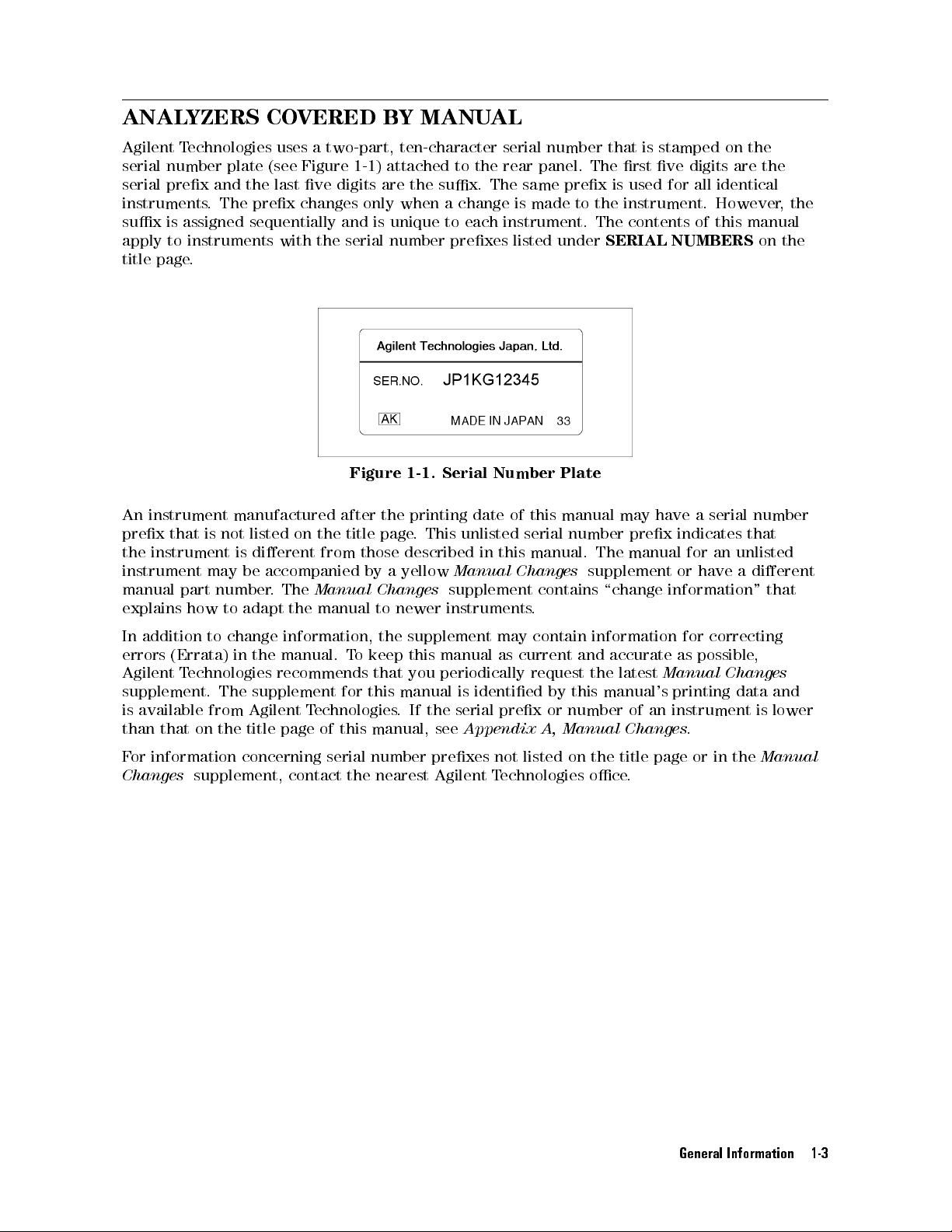
ANALYZERS
COVERED
BY
MANUAL
Agilent
serial
serial
T
echnologies
number
prex
instruments
sux
is
assigned
apply
to
instruments
title
page
.
An
instrument
prex
the
that
instrument
instrument
manual
explains
part
how
plate
and
the
.
The
prex
sequentially
manufactured
is
not
listed
is
dierent
may
be
accompanied
number
to
adapt
uses
(see
last
with
.
The
the
a two-part,
Figure
ve
digits are
changes
and is
the
after
on
the
from
Manual
manual
ten-character serial
1-1
) attached
only
when a
unique to
serial
number prexes
Figure
the
title
page
those
described
by
a
yellow
Changes
to
newer
to the
the sux.
change is
each instrument.
1-1. Serial
printing
.
This
date
unlisted
Manual
supplement
instruments
number that
rear panel.
The same
made to
listed under
Number Plate
of
this
manual
serial
in
this
manual.
Changes
contains
.
is stamped
The rst
prex is
used for
the instrument.
The contents
SERIAL NUMBERS
may
have
number
The
prex
manual
supplement
\change
on the
ve digits
all identical
However,
of
this
a
serial
indicates
for
an
or
have
information"
are the
manual
on
number
that
unlisted
a
dierent
that
the
the
In
addition
errors
Agilent
supplement.
is
available
than
F
or
information concerning
Changes
(Errata)
T
echnologies
that
on
supplement,
to
change
The
from
the
in
the
supplement
Agilent
title
information,
manual.
T
o
recommends
for
T
echnologies
page
of
this
serial number
contact the
the
supplement
keep
this
manual
that
you
periodically
this
manual
.
If
is
the serial
manual, see
prexes not
nearest Agilent
may
contain
as
current
request
identied
prex or
Appendix A,
listed
Technologies
information
and
accurate
the
latest
by
this
manual's printing
number of
Manual Changes
on
the
title
oce.
for
correcting
as
possible
Manual Changes
data and
an instrument
.
page
or
in
the
,
is
lower
Manual
General Information 1-3
Page 28
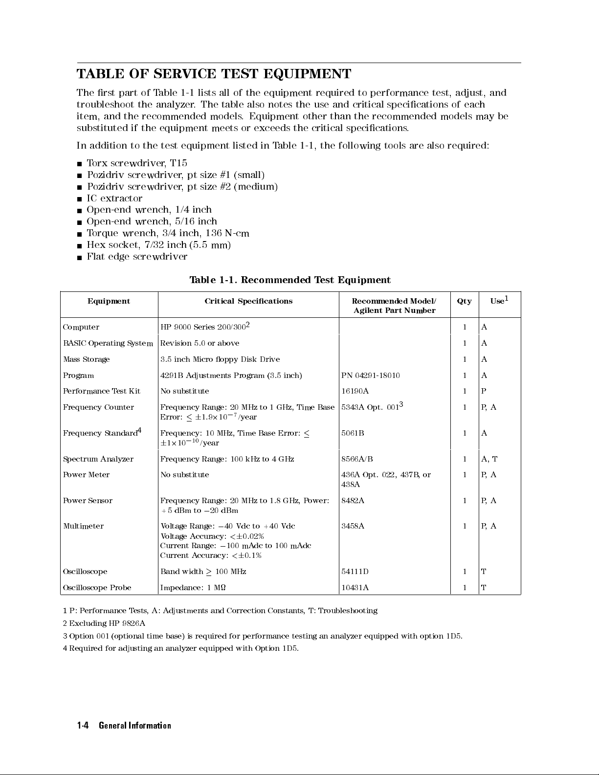
TABLE
The
rst
part
troubleshoot
item,
and
the
substituted
In
addition
T
orx
screwdriver
P
ozidriv
P
ozidriv
IC
extractor
Open-end
Open-end
T
orque
wrench, 3/4
Hex
socket,
Flat
edge
OF SERVICE
of
Table
1-1 lists
the
analyzer
.
The
recommended
if
the
equipment
to
the
test equipment
,
T15
screwdriver
screwdriver
wrench,
wrench,
,
pt
size
,
pt
size
1/4 inch
5/16 inch
inch, 136
7/32 inch
(5.5 mm)
screwdriver
T
able
TEST EQUIPMENT
all of
table
models
meets
listed in
the equipment
also notes
.
Equipment other
or
exceeds the
Table
required to
the use
critical specications
1-1,
#1 (small)
#2 (medium)
N-cm
1-1.
Recommended
T
est
and critical
than the
the
following
Equipment
performance test,
adjust, and
specications of
recommended models
.
tools
are
also
required:
each
may be
Equipment Critical
Computer HP
B
ASIC
Mass
Operating
Storage
System
Program 4291B
P
erformance
Frequency
Frequency
T
est
Kit
Counter
Standard
4
9000
Series
Revision
3.5
No
5.0
inch
Micro
A
djustments Program
substitute
Frequency
Error:
Frequency:
0
6
10
1
2
10
Range:
6
1.9
/year
or
2
10
200/300
above
oppy
10
MHz,
Spectrum Analyzer Frequency Range:
Power
Meter
No substitute 436A Opt.
Specications
2
Disk
Drive
20
MHz
7
/year
Time
to
Base
to 4
0
100 kHz
(3.5
1
inch)
GHz,
Error:
GHz
Time
Recommended
Agilent
PN
04291-18010
P
art
Model/
Number
16190A 1 P
Base
5343A
Opt.
001
3
5061B 1 A
8566A/B 1 A, T
022
,
437B
,
or
Qty Use
1 A
1 A
1 A
1 A
1 P
1 P,
438A
P
ower Sensor
Multimeter V
Frequency
+5
dBm
oltage
Range:
Voltage A
to
ccuracy:<6
Current Range:
Current A
Oscilloscope Band width
Range: 20
0
20 dBm
0
40
Vdc
0
100 mA
ccuracy:<6
100 MHz
MHz to
1.8 GHz,
to
+40
0.02%
dc to 100 mA
0.1%
Power:
Vdc
dc
8482A 1 P
3458A 1 P
54111D 1 T
Oscilloscope Probe Impedance: 1 M 10431A 1 T
,
A
A
,A
,
A
1
1
P: P
erformance T
2
Excluding HP 9826A
3
Option 001 (optional time base) is required for performance testing an analyzer equipped with option 1D5.
4
Required for adjusting an analyzer equipped with Option 1D5.
ests,A: A
djustments
and Correction Constants
, T: Troubleshooting
1-4 General Information
Page 29
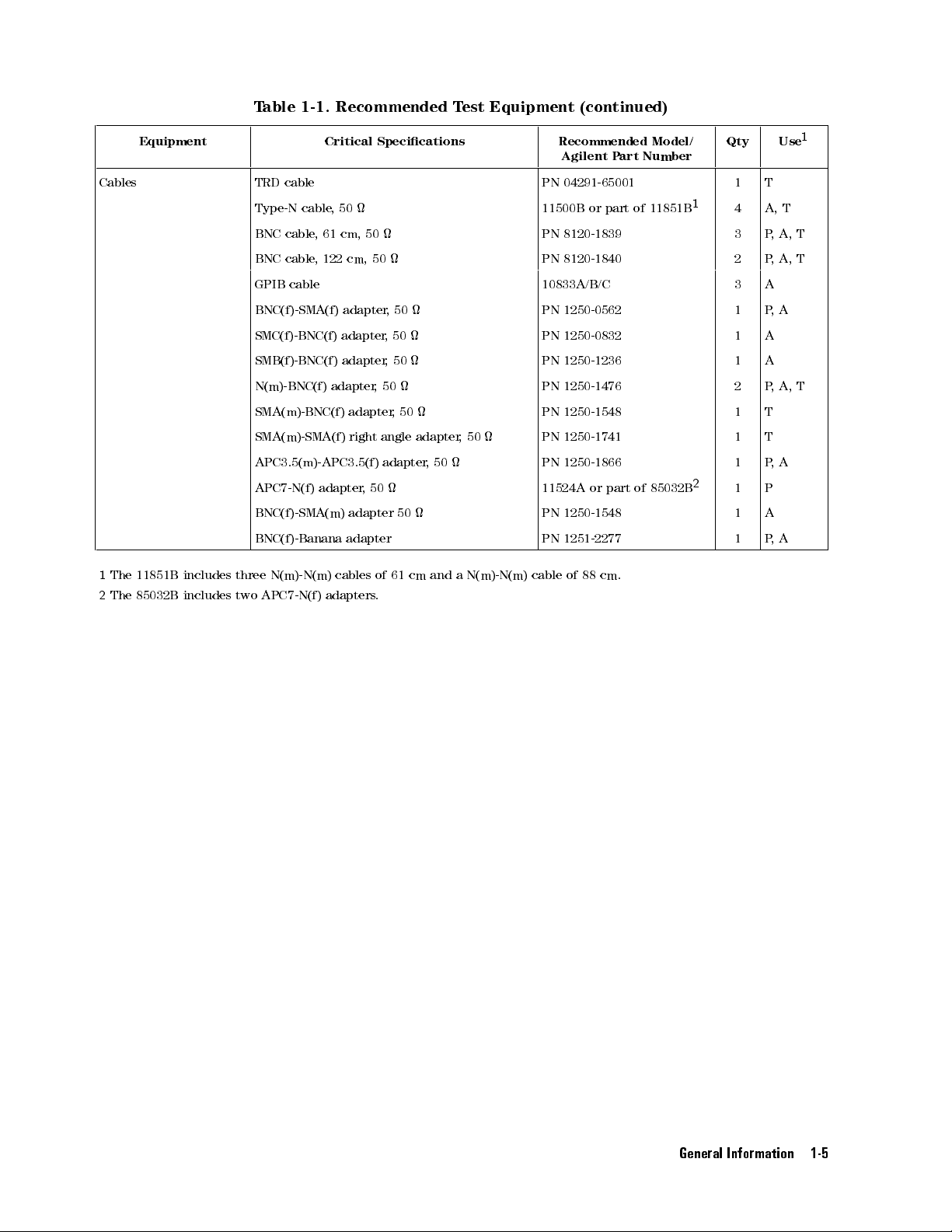
T
able 1-1.
Recommended T
est Equipment
(continued)
Equipment Critical
Cables TRD
Type-N cable
BNC
BNC
GPIB
BNC(f)-SMA(f)
SMC(f)-BNC(f)
SMB(f)-BNC(f)
N(m)-BNC(f)
SMA(m)-BNC(f)
SMA(m)-SMA(f)
APC3.5(m)-APC3.5(f)
APC7-N(f)
BNC(f)-SMA(m)
BNC(f)-Banana
1
The
11851B
2
The
85032B
includes
three
includes two
N(m)-N(m)
APC7-N(f)
cable
cable,
cable
cable
,50
61
cm,
,
122
adapter
adapter
adapter
adapter
adapter
cables
adapters
Specications
50
cm,
50
,
,
,
,
50
adapter
right
angle
adapter
,
50
adapter
adapter
of
.
61
50
50
50
,
50
50
adapter
cm
,A,
,
A,
1
T
T
Recommended
Agilent P
PN
04291-65001
11500B or
PN
8120-1839
PN
8120-1840
art
part of
Model/
Number
11851B
1
Qty Use
1 T
4 A, T
3 P
2 P
10833A/B/C 3 A
PN
1250-0562
PN
1250-0832
PN
1250-1236
PN
1250-1476
PN
PN
PN
11524A
PN
PN
cable
1250-1548
1250-1741
1250-1866
or
part
1250-1548
1251-2277
of
88
cm.
of
85032B
,
50
,
50
and
a
N(m)-N(m)
1 P
,
A
1 A
1 A
2 P
,
A,
T
1 T
1 T
1 P
,
A
2
1 P
1 A
1 P
,
A
General Information 1-5
Page 30

Page 31

P
erformance T
INTRODUCTION
This
chapter
performance
provides
tests
are
the 4291B
used to
ests
RF Impedance/Material
verify that
the analyzer's
Analyzer performance
performance meets
its
tests
.
These
specications
2
.
General
procedures
The
Description:
Specication:
T
est
Procedure:
information about
for each
each test
procedure consists
Equipment:
the performance
test are
provided.
Describes the
Describes
Describes
Describes
GENERAL INFORMA
This
section
W
arm
Allow
performance
Ambient
P
erform
provides
Up
Time
the
analyzer
Conditions
all
performance
tests
to
.
general
warm
tests
up
of the
test procedure
the
performance veried
test
the
test
TION
information
for
at
least
in
ambient
tests is
following
equipment
procedure
about
the
30 minutes
conditions
provided
parts:
.
required
step
performance
before you
of 23
rst.
Then,
step
by
step
in
the
test.
in
the
test.
by
step
.
tests
.
execute
C,
6
5
70%RH.
any
of
the
Calibration Cycle
The analyzer requires periodic
of performance verication depends on
which the analyzer is used. V
performance tests given in this chapter
Performance T
est Record
The performance test record lists all test
performance verication to remain in calibration. The frequency
the operating and environmental conditions under
erify the analyzer's performance at least once a year using the
.
points, acceptable test limits
, test result entry
columns, and measurement uncertainties. The measurement uncertainty shows how accurately
the analyzer's specications are measured and depends on the test equipment used. The listed
measurement uncertainties are valid only when the recommended test equipment is used.
The performance test record is provided at the end of this chapter. Use this record as a master
to make extra copies for performance testing.
Performance Tests 2-1
Page 32

Recommended
T
able
1-1
lists
the
may
be
substituted
T
able
1-1
.
T
est
Equipment
equipment
if
the
equipment
required
for
performance
meets
or
exceeds the
testing
the analyzer
critical specications
. Other
given in
equipment
2-2 Performance Tests
Page 33

FREQUENCY A
Description
This
test
uses
a
frequency counter
signal
when
it
is
tuned
frequency
Specication
(See
reference
the
Specications
(or
CCURACY
to measure
to
1 GHz.
the
of
Operating
high
This test
stability
TEST
the actual
checks the
frequency reference
Manual Set
for
frequency of
frequency accuracy
for Option
details
.)
the analyzer
of
the
1D5).
stimulus
internal
Frequency
A
ccuracy
@
Precision
A
ccuracy
@
T
est
Equipment
Frequency
BNC
cable,
APC3.5(m)-APC3.5(f)
N(m)-BNC(f)
BNC(f)-SMA(f)
1
:
Option
2
:
This
adapter
\connector
APC
3.5
and
connector
Procedure
1.
Connect
Option
REF
reference
C
23
6
5
frequency reference
C
0
to
55
Counter
61 cm
adapter
adapter
001
time
is
saver").
Input
connector
care
the
test
1D5,
connect
O
VEN
connector
::
:
:
:
:
:
:
C
:
:
::
:
:
:
:
:
:
:
:
adapter
:
base is
used
to
In
the
,
see
MICRO
equipment
a
:
:
:
:
:
:
:
:
:
:
:
::
::
(Option
:
:
:
:
:
:
:
:
:
:
:
:
:
:
:
:
:
:
::
::
:
:
:
:
:
:
:
:
:
:
:
:
:
:
:
:
:
:
:
:
:
2
::
:
:
:
:
:
:
:
::
:
:
:
:
required
protect
test
setup
through
W
as
BNC(m)-BNC(m)
on
the
:
:
::
::
:
:
:
:
:
:
:
:
:
:
:
:
:
:
:
for
the
5343A
,
the
this
adapter
A
VE
CONNECTOR
shown
analyzer
::
::
:
:
:
:
:
:
:
1D5)
:
:
:
:
:
:
:
:
:
::
:
:
:
:
:
:
:
:
:
:
:
:
:
:
::
::
:
:
:
:
:
:
:
:
:
:
:
:
:
:
:
:
:
:
:
:
:
:
:
:
:
:
:
:
:
::
:
:
:
:
:
:
:
:
:
:
:
:
testing
the
's
APC
BNC(m)-SMA(f)
.
F
or
in
Figure
cable
between
rear
panel.
:
:
:
:
:
:
:
:
:
:
:
:
:
:
:
:
::
::
:
:
:
:
:
:
:
:
:
:
:
:
:
:
:
:
:
:
::
:
:
:
:
analyzer
3.5
Input
more
CARE
2-1
.
For
:
:
:
::
::
::
::
:
:
:
:
:
:
:
:
:
:
:
:
:
:
:
:
:
:
:
:
:
:
:
:
:
:
:
::
:
:
::
::
:
:
:
:
:
:
:
:
:
:
:
:
:
:
:
:
:
:
:
:
:
:
:
:
with
option
connector
adapter
information
(PN
08510-90064).
testing the
the
EXT
:
:
:
:
:
:
:
:
:
:
:
:
:
:
:
:
:
::
:
:
:
:
:
:
:
:
:
:
:
:
:
:
:
:
::
::
:
:
:
:
:
:
:
:
:
:
:
:
:
:
:
:
:
:
:
:
:
:
:
:
:
:
:
:
:
::
:
:
:
:
:
:
:
:
:
:
:
:
::
:
1D5.
(it
is
is
connected
on
microwave
analyzer equipped
REF
Input
:
:
:
:
:
:
::
<
6
:
:
:
:
:
:
:
:
:
<
::
:
:
:
:
:
:
:
:
:
:
:
:
:
:
:
:
PN
8120-1839
:
:
:
:
:
:
PN
1250-1866
:
:
:
:
:
:
PN
1250-1476
:
:
:
:
:
:
PN
1250-0562
sometimes
to
connector and
called
the
5343A
connectors
10 ppm
6
1
ppm
5343A
's
with
the
1
a
Performance Tests 2-3
Page 34

Figure
2-1.
Frequency
A
ccuracy
Test
Setup
Note
2.
Initialize
Controls
Sample
Range
INT/EXT
Switch
panel)
3.
Press
Control
Settings
Frequency
Span: ZERO
Center
Frequency:
1 GHz
the
Rate
Switch
(rear
4
Preset
An APC3.5(m)-APC3.5(f)
and
the
5343A
connector
mated
with
frequency
.
In
Figure
the
counter
's
APC
APC
.
Settings
Midrange
500
MHz-26.5
MHz
Internal
5
to
initialize
the
analyzer
Keystrokes
5
5,4
5,4
0
5,4
5,4
1
x1
G/n
5
4
Span
4
Center
3.5
2-1
3.5
Then
adapter
Input
,
the
SMA
connector
set
the
.
Then
is
used
connector
connector
of
controls
set
the
between
to
a
dierent
as
controls
the
protect
of
the
type
follows:
as
follows:
BNC(f)-SMA(f)
the
5343A
's
BNC(f)-SMA(f)
.
adapter
APC
adapter
3.5
Input
is
OSC Level: 0.2V4
Source
5,4
5,4
.
x1
2
5
5,4
4. Wait for the frequency counter reading to settle.
5. Subtract 1 GHz (analyzer setting) from the frequency counter reading, and record the result
on the performance test record.
2-4 Performance Tests
Page 35

OSC LEVEL
Description
This
test
uses
a
stimulus
Specication
(See
OSC
where
T
est
P
P
APC-7
Fixture
T
Extension
signal
the
Specications
level
,
A
depends
when
@
other
B
depends
@
P
osc
@
0
5
@
other
Equipment
ower
Meter
ower
Sensor
R
-N(f)
Stand
est
Stage
at
accuracy
referenced
environmental
on
0
dBm
OSC
Stand
Rod
ACCURA
power meter
several
on
temperature
OSC
5
dBm
>
:
:
:
:
:
:
:
A
dapter
(only
(only
(only
P
osc
levels
:
:
::
:
:
:
:
for
:
for
frequencies
of
Operating
:
:
:
to
level
:
:
:
:
::
:
:
::
:
:
::
:
High T
for High
High
CY TEST
and a
:
:
:
:
:
:
:
:
conditions
C
23
6
5
temperature
as
follows:
:
:
:
:
:
:
:
:
0
45
dBm
:
:
:
:
::
::
:
:
:
:
:
:
:
:
:
:
:
:
:
:
:
:
:
:
:
:
:
:
:
:
emp
T
Temp
power sensor
from
1MHz
Manual
:
::
::
::
::
:
:
:
as
follows:
:
:
:
:
:
:
:
:
:
:
::
conditions
:
:
:
:
:
::
:
:
:
:
:
:
:
:
:
:
::
::
::
:
:
:
:
:
:
:
:
:
:
:
:
:
:
:
:
:
:
:
:
:
::
:
:
:
:
:
:
:
:
:
:
:
:
:
:
:
:
:
:
:
:
:
:
:
:
.
T
est
Heads)
emp
.
T
est
Heads)
.
T
est
Heads)
to measure
to 1.8
Set
for
:
:
:
:
:
:
:
::
::
::
:
:
:
:
:
:
:
::
:
:
:
:
:
:
:
:
:
:
:
::
:
:
:
:
:
::
:
:
:
:
:
::
:
:
:
:
:
:
details
:
:
:
:
:
:
:
:
:
:
:
:
:
:
:
:
:
:
:
:
:
:
:
:
:
:
:
:
:
:
:
:
::
:
:
:
:
:
:
:
:
:
:
:
:
:
:
:
:
:
GHz.
:
:
:
:
:
:
:
::
:
:
.)
:
:
::
:
:
:
:
:
:
:
::
:
:
:
:
:
:
:
:
::
:
:
:
:
:
:
:
:
:
:
:
:
:
:
:
:
:
:
:
:
:
:
:
:
:
the actual
::
::
::
:
:
:
:
:
:
:
:
:
:
:
::
::
::
::
:
:
:
:
::
:
:
:
:
:
:
:
:
:
:
::
::
:
:
:
:
:
:
:
:
:
:
:
:
:
:
436A
:
:
:
:
:
:
:
:
:
:
:
:
:
:
:
:
:
:
:
:
:
:
:
:
:
::
:
:
:
:
:
:
:
:
::
:
:
:
:
:
:
:
:
::
power level
:
:
:
:
:
A
+
::
::
::
:
:
:
:
:
:
:
:
:
:
:
:
:
:
:
:
:
:
:
::
:
:
:
:
:
:
:
:
:
:
:
:
:
:
:
Opt.
022
:
::
:
:
:
:
:
:
:
::
:
:
:
:
:
:
:
:
:
:
:
:
:
:
:
:
:
:
:
:
:
:
:
:
:
:
:
B
:
:
:
:
:
:
:
:
:
:
::
:
:
:
:
:
:
:
:
:
:
:
:
:
:
of
the
6[
dB
+
:
:
:
:
:
:
:
:
:
:
:
:
::
::
:
:
:
:
:
:
:
::
:
:
:
:
:
:
:
:
::
::
:
:
:
:
,437B
,or
:
:
:
:
:
:
:
:
:
:
:
:
:
:
:
:
PN
04291-60121
PN
04291-65021
PN
04291-65022
]
2
f
[
M
1800
:
:
:
:
2
::
::
4
:
:
:
0
:
:
::
1dB
:
:
:
:
2
438A
:
:
8482A
:
11524A
H
dB
dB
dB
dB
z
]
Procedure
The
OSC
Note
analyzer
following
1.
Connect
sensor.
2. Connect the test equipment as shown in Figure 2-2 .
the
power
level accuracy
because
test
procedure is
sensor
to
the
the test
test must
head characteristics
common for
power
meter
be done
.
Calibrate the
for
all test
all
test
heads
aect the
heads.
power
OSC
meter
attached
level.
for
the
to
The
power
the
Performance Tests 2-5
Page 36
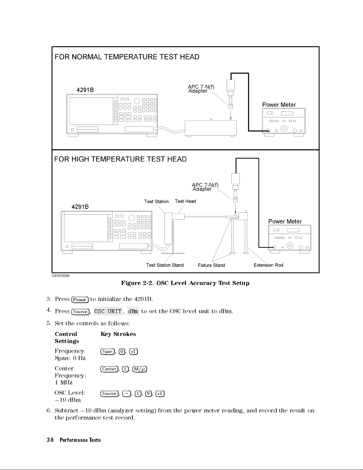
Figure
2-2.
OSC
Level
A
ccuracy
T
est
Setup
3. Press
4.
Press
4
Preset
4
Source
5
to
5
,
initialize
N
N
N
NN
NN
NN
NN
N
N
OSC
UNIT
the
4291B
.
N
N
N
NN
NN
NN
N
N
N
N
N
N
N
N
N
N
NN
N
N
N
dBm
,
to set
the OSC
level unit
to dBm.
5. Set the controls as follows:
Control
Key Strokes
Settings
Frequency
4
Span
5,4
0
5,4
x1
5
Span: 0 Hz
Center
4
Center
5,4
1
5,4
M/
5
Frequency:
1 MHz
OSC Level:
0
19 dBm
4
5,405,415,495,4x15
Source
6. Subtract019 dBm (analyzer setting) from the power meter reading, and record the result on
the performance test record.
2-6 Performance Tests
Page 37

7.
Change
numeric
the analyzer
keys
to
test
T
able
OSC level
the
analyzer
2-1.
T
est
and frequency
at
the following
Setting
for
settings,
Normal
N
NN
OSC
using
test points:
T
emperature T
NN
NN
NN
NN
NN
NN
LEVEL
est Heads
N
NN
NN
NN
NN
NN
NN
NN
N
N
N
N
N
N
N
N
N
N
N
N
N
NN
N
Center
,
N
N
N
, and
the
T
able
OSC
0
0
0
0
0
0
0
0
0
2-2.
Level
19
dBm
19 dBm
19
dBm
19
dBm
19
dBm
19
dBm
19
dBm
19
dBm
13
dBm
0
7
dBm
0
7
dBm
0
7
dBm
T
est
OSC
0
19
0
13
0
Setting
Center
200
300
500 MHz
800 MHz
Level
dBm
dBm
7
dBm
1
dBm
7
dBm
Freq.
1 MHz
15
1.2
1.5
10
1
10
15
for
MHz
MHz
MHz
GHz
GHz
MHz
MHz
MHz
MHz
Center
High
OSC
Freq.
1 MHz
10
MHz
100
MHz
1.8
GHz
1
GHz
T
emperature
Level
0
7
dBm
0
7 dBm
0
7
dBm
0
7
dBm
0
7
dBm
0
7
dBm
0
7
dBm
0
7
dBm
0
7
dBm
1
dBm
1
dBm
T
Center
100 MHz
200
300
500
800 MHz
est
1 GHz
1.2
1.5
1.8
1
1
Heads
Freq.
MHz
MHz
MHz
GHz
GHz
GHz
MHz
GHz
Performance Tests 2-7
Page 38

MEASUREMENT A
Description
In
this
test,
calibrated
the
analyzer
calibration
Specication
(See
the
.
Then
values
Specications
standards (from
the
analyzer
.
of
CCURACY
the 16190A
measurement values
Operating
Manual
TEST
Set
Performance
are compared
for
details
.)
Test
with the
Kit) are
measured with
standards'
Measurement
Test
Equipment
P
erformance
3/4
inch
T
Fixture
T
est
Extension
Procedure
Note
Save
Note
Stand
Stage Stand
the
Analyzer
A
ccuracy
T
est
Kit
orque
Wrench,
(only
for
(only for
Rod
(only for
Measurement
analyzer
following
Setup
The
ve
test. The
measurement to
mV/250
skipped,
:
:
:
:
:
:
:
:
:
:
:
136
High
T
High T
High T
accuracy
because
test
procedure
calibrated
analyzer
mV
setup
if
the
status
:
:
:
:
:
:
:
:
:
:
N-cm
emp
emp
emp.
the
standards
setup
reduce
and
:
:
::
::
::
:
:
:
:
::
::
:
:
:
:
:
.
T
est
.
T
est
Test
test
test head
is
for
setup
41
mV
is
already
::
:
:
:
:
:
:
:
:
:
:
:
:
:
:
:
:
:
:
:
:
:
:
:
:
:
:
:
:
:
Heads)
Heads)
must be
common for
:
:
Heads)
:
:
done
characteristics
are
measured
the
test
time
.
The
setup
are
saved.
:
:
:
:
:
:
::
:
:
:
:
:
:
:
:
:
is
:
:
:
:
:
:
:
:
:
:
:
:
:
:
:
:
:
:
:
:
:
:
:
:
:
:
:
:
:
:
for
all
test
in
saved,
two
saved.
:
:
::
:
:
:
:
:
:
:
:
:
:
:
:
:
:
:
:
all
aect
the
and
setups
This
::
::
:
:
:
:
:
:
:
:
test
heads
::
::
:
:
:
:
:
Basic
::
:
:
:
:
:
:
:
:
:
:
:
:
:
:
:
:
:
:
:
:
:
:
:
:
:
:
:
:
:
:
:
:
:
:
::
::
::
:
:
:
:
:
:
::
::
::
::
:
:
:
heads
attached
the
measurement.
.
measurement
recalled
for
saving
in
each
procedure
:
:
:
:
:
:
test
:
:
:
:
::
:
:
:
:
each
A
ccuracy:
:
:
:
:
:
:
:
:
:
:
PN
PN
04291-60121
:
PN
04291-65021
:
PN
04291-65022
to
accuracy
standard
head
0.8%
:
::
16190A
8710-1766
the
The
of
400
can
be
1.
Connect the
2-8 Performance Tests
test equipment
as shown
in Figure
2-3
.
Page 39

Figure 2-3.
Measurement A
ccuracy
T
est
Setup
2.
3.
Press
Press
4
Preset
4
Sweep
5
to
initialize the
N
N
N
N
N
N
N
N
N
N
N
LIST
5
,
NN
NN
4. Create the sweep list
analyzer.
N
N
N
N
N
N
N
N
N
N
N
NN
NN
NN
NN
N
N
NN
NN
N
N
N
MENU
N
N
N
N
N
N
N
EDIT
,
N
N
N
LIST
N
N
N
N
N
to
call
the
sweep list
editor.
shown in Figure 2-4, using the following procedure:
Performance Tests 2-9
Page 40

a.
Press
segment
N
N
N
N
N
N
N
EDIT
Figure 2-4.
N
N
N
N
N
N
N
.
Then
as
follows:
Sweep List
if
the
normal
for Measurement
temperature
test
head
Accuracy
is
connected,
T
est
edit
the rst
Control
Stop
10
OSC
mV
A
veraging on
P
oint: 8
b. If
the high
Control Settings
Stop
10
OSC
mV
Averaging on
Point: 8
c.
Press
d.
Press
e.
Edit all the necessary segments
5.
Press
6.
Press
unit of channel 2 to rad.
Settings
Frequency:
MHz
Level:
Frequency:
MHz
Level: 250
4
Sweep
4
Ch2
400
temperature
NNNNNNNNNNN
NNNNNNNNNNNNNNNNNNNNNNNNN
SEGMENT DONE
NNNNN
NNNNNN
ADD
to display the second segment. Then edit the segment in the same manner
NNNNNNNNNNNNNNNNNNNNNNNNNNNNNNNN
5
,
SWEEP MENU
5,4
Format
5
, and toggle
K
ey
Strokes
4
5
5
5
,
,
4
Stop
N
N
N
N
N
N
N
N
N
OSC
N
N
N
N
N
N
N
NN
AVERAGING
Key
4
Stop
N
N
N
N
N
N
N
NN
OSC
N
N
N
NN
N
N
N
N
AVERAGING ON POINT
NN
to
4
1
0
N
N
N
N
N
N
N
NN
N
N
N
N
N
N
N
N
N
N
N
LEVEL
NN
N
N
N
N
N
N
N
N
N
N
N
N
N
N
N
N
N
N
test
head
Strokes
5
5
5
,
,
4
4
1
0
NN
NN
NN
N
N
N
N
N
N
N
N
N
N
N
N
N
N
LEVEL
N
N
N
N
N
N
N
NN
N
N
N
N
N
N
N
N
N
N
NN
store the segment.
NNNNNNNNNNNNNN
,
LIST
NNNNNNNNNNNNNNNNNNNNNNNNNNNNNNNNNNNNNNNNNNNNNNNNNN
PHASE UNIT [DEG]
5
,
4
M/
5
5
,
,
4
,
4
0
4
N
N
N
NN
NN
N
N
N
N
N
N
N
N
N
N
N
N
N
POINT
is
connected,
5
4
M/
5
5
,
4
2
5
N
N
N
N
N
N
N
N
NN
N
N
N
N
N
,
N
N
N
ON
,
,
4
N
N
N
. Then press
to activate the list sweep.
5
,
4
0
N
N
N
N
N
N
,
5
4
,
0
N
N
N
NN
N
,
5
for
4
k/m
5
5
,
4
4
8
x1
edit
5
4
for high
k/m
5,4x15
4
8
NNNNNNNNNNNNNNNN
NNNNNNNNNNNNN
LIST DONE
to
normal
the
NNNNNNNNNNNNNNNNNNNNNNNNNNNNNNNNNNNNNNNNNNNNNNNNNN
PHASE UNIT [RAD]
temperature
rst
segment
temperature test
to complete the sweep list.
as
test
heads
follows;
heads
.
to set the phase
7. Press
2-10 Performance Tests
4
5
to activate channel 1.
Ch1
Page 41

8.
Press
9.
T
oggle
recommended
10.
Press
5
4
Save
N
NN
NN
NN
NN
STOR
N
N
N
N
N
N
N
N
N
N
NN
STATE
to enter
NN
N
N
N
N
N
N
N
N
N
N
N
NN
NN
NN
DEV [DISK]
because
NN
NN
N
to
select
the save
NN
NN
NN
NN
N
N
N
N
status
N
N
N
N
the
N
menu.
N
N
or
internal
save
N
NN
NN
NN
NN
NN
N
N
N
N
N
N
STOR
DEV [MEMORY]
memory
.
N
NN
NN
NN
NN
NN
N
N
N
N
N
N
N
NN
NN
NN
NN
NN
NN
NN
N
N
N
N
N
N
N
N
N
N
N
NN
NN
NN
data
to select
is
lost
when
the storage
the analyzer
device.
power is
DISK
N
is
o.
11. Save
When
the
now
When
status
saved.)
12.
Press
13.
Change
a.
b.
c.
d.
e.
f.
14.
Press
15.
Press
16.
Press
at
41
the status
the
status
saved.)
the High
with
4
Sw
eep
all
Press
Press
Press
Press
Edit
the
Press
4
Save
N
N
N
N
N
N
N
N
STATE
5
4
,
4
mV
Normal
with
a
N
N
N
N
N
LIST
5
,
OSC
N
N
N
N
N
N
N
N
N
N
N
N
N
N
N
N
SEGMENT
N
N
N
N
N
N
N
N
N
N
N
N
N
N
EDIT
N
N
N
N
N
N
N
N
N
N
N
N
N
N
NN
OSC
LEVEL
N
N
N
N
N
N
N
N
NN
NN
N
N
N
N
SEGMENT
other
N
N
N
N
N
N
N
N
N
N
N
N
N
N
N
N
LIST
5
to
enter
N
N
N
N
N
N
N
NN
to
N
N
N
N
N
DONE
5
,
4
1
OSC
level
as;
T
emperature
a
le
name
Temperature
le
name
N
N
N
N
N
N
N
N
N
N
N
NN
NN
NN
NN
N
N
MENU
level
settings
N
N
N
N
N
NN
5
,
,
4
4
1
to edit
NN
N
N
N
N
DONE
N
N
N
NN
N
N
N
N
N
N
N
N
N
,
4
N
N
N
N
N
N
N
N
N
N
N
N
N
N
N
DONE
segments
N
NN
NN
N
N
N
N
N
N
to
the
select
N
NN
N
N
N
to
is
now
the segment.
5
4
NN
NN
status
save
of
Test
of
\250.ST
N
N
N
N
N
N
N
N
N
N
N
N
EDIT
,
5
to
5
4
1
to
in
the
saved.)
N
to 41
select
,
4
k/m
store
the
menu.
only
N
N
x1
,
N
complete
save
T
est
Head
\400.ST
N
N
N
N
LIST
status with
A".
Head
A". (The
NN
NN
NN
NN
N
N
N
N
N
to
mV,
using
the
rst
5
to
set
the segment.
same
manner
the
sweep
save
.
is
connected, press
(The
setup
is
connected,
setup for
call
the
sweep
the
following
segment.
the
OSC
level
.
list.
ale
name
for
the
press
the test
list
editor
procedure:
to
41
of
\41.ST
test
5
4
2
at 250
mV
4
4
,
.
A".
N
N
N
N
N
N
N
N
N
NN
NN
N
DONE
OSC level
N
N
N
N
N
N
N
to save
level
for
to
save
is
the
is
the
now
test
5
,
at
5
4
5
.
4
0
,
4
(The
,
400
5
0
mV
4
0
N
,
,
mV
NN
NN
NN
DONE
OSC
setup
5
5
Analyzer
Note
17. Press
to recall the sweep list setup.
18.
Press
19.
Connect the 0 S termination of the analyzer calibration kit to the test head APC-7
connector.Thenpress
Calibration
Calibration must
calibration
Calibration
calibration
The analyzer furnished calibration kit must be used for calibration. Do not use
the
16190A performance test kit.
Do not
performance is specied
Calibration must be done
4
5
,
Recall
NNNNNNNNNNNNNNNNNNNNNNNNNNNNNNNNNNNNNNNNNNNN
4
5
,
CALIBRATE MENU
Cal
perform the low-loss capacitor calibration because the analyzer
NNNNNNNNNNNNNNNNNNNNNNN
400.STA
data
must
data
NNNNNNNNNNNNNNNNNNNNNNN
(or
NNNNNNNNNNNNNN
OPEN
be
done
when
the
test
is
valid
only
for
the
test
be
done
when
the
analyzer
is
erased
250.STA
to start the calibration.
to do the open calibration.
when
turned
without the low-loss capacitor calibration.
for each sweep list setting.
when the High Temperature Test Head is being tested)
head
head
OFF
is
.
is
replaced
used
turned
in
because
the
calibration.
ON
because
Performance Tests 2-11
the
the
R
Page 42

20.
Disconnect
calibration.
21.
calibration.
22. Press
23.
Press
to overwrite
24. Press
25.
Repeat
26.
Press
the 0
the
NN
NN
NN
N
N
N
N
N
N
N
N
N
N
N
N
step
N
N
N
N
N
RE-SAVE
5
,
the
NN
41.STA
5
,
list
N
N
N
N
RE-SAVE
5
,
DONE CAL
4
Save
4
Recall
4
Save
S, and
0
,
and
NN
NN
NN
N
to complete
N
N
N
N
N
N
N
N
N
NN
NN
NN
NN
status
NN
N
N
N
N
N
N
N
N
N
N
N
N
N
item
N
N
N
N
N
N
N
N
N
N
N
N
NN
NN
connect the
connect
N
N
N
N
N
N
N
N
N
N
N
N
N
FILES
data
N
N
N
to
recall
18
to
NN
NN
N
N
N
N
N
N
N
N
N
N
FILES
the
the calibration.
N
N
N
N
N
N
N
N
N
N
N
N
N
N
N
N
N
N
N
NN
list
N
N
N
N
N
,
with
N
,
NN
400.STA
calibration
the
sweep
item
22
N
N
N
N
N
N
N
N
N
N
N
N
N
N
41.STA
0
termination, then
50
termination,
N
N
N
N
N
N
N
NN
NN
NN
N
N
(or
with
N
N
NN
NN
to
N
250.STA
data.
list
setup
41.STA
overwrite
N
N
N
N
N
NN
NN
NN
for
then press
NN
N
N
for
41
setting.
the
status
press
the
mV
N
NN
NN
NN
SHORT
N
N
N
LOAD
High
setting.
data
NN
NN
NN
NN
N
N
to do
N
N
N
N
N
N
NN
NN
N
to
do
T
emperature
with
calibration
the short
the
short
T
est
Head)
data.
Open
27.
Record
28.
Connect
connection
29.
Recall
30.
Press
31.
Press
32.
Press
33.
Subtract
test
34.
Press
35.
Press
36.
Press
37.
Press
Measurement
the
open
the
open
to
136
the
test
settings
When
the
When
250
the
400
the
mV
4
meas
4
T
rigger
4
Cop
the
results
4
Recall
4
meas
4
Trigger
4
Copy
Normal
mV
settings
High
settings
N
N
N
N
N
DUAL
5
,
N
N
SINGLE
5
,
N
N
N
N
N
MORE
5
,
y
open
on
N
N
NN
41.STA
5
,
N
N
N
N
N
DUAL
5
,
N
N
SINGLE
5
,
NNNNNNNNNNNNNN
MORE
5
,
N
N
N
N
N
N
N
N
the
NN
N
N
N
N
N
T
est
termination
termination
N-cm.
and
T
emperature
.
T
emperature
.
N
N
N
N
N
NN
N
N
N
N
N
N
N
N
N
N
N
N
N
N
PARAMETER
N
N
N
NN
N
N
N
N
N
N
N
N
N
N
N
to
N
N
N
N
N
N
N
N
N
N
N
N
N
N
NN
N
N
N
N
NN
NN
N
N
N
N
N
LIST
,
calibrated
performance
N
N
N
N
N
N
N
N
N
N
to recall
NN
NN
NN
N
N
N
N
N
N
N
N
N
N
N
PARAMETER
N
N
N
N
N
N
N
N
NN
N
N
to make a measurement.
NNNNNNNNNNNNNNNNNNNNNN
LIST VALUES
,
the
N
N
N
N
N
N
N
N
N
make a
N
N
N
N
NN
NN
N
N
VALUES
N
N
N
N
N
N
NN
NN
calibration
to
the
calibration
T
est
T
est
N
N
N
N
N
N
N
N
NN
N
N
NN
NNNNNNNNNNNNN
N
N
N
N
N
|Y|-
,
measurement.
N
N
N
N
N
N
N
N
N
N
N
N
to
values
test
the 41
N
N
N
N
N
N
N
N
N
NN
N
|Y|-
,
to display the test results
test
Head
Head
N
N
N
N
NN
N
N
to
display
from
record.
mV
N
NN
NN
NN
N
to
values
head
data.
is
connected,
is
connected,
set
the
the
the
analyzer
test
settings
set
the
on
the
performance
R
APC-7
press
measurement
test
results
\
j
and
measurement
connector
press
4
Recall
4
Recall
parameter
.
Y
j
"
display values
the
calibration
parameter to
.
test
.
Then
5
,
N
N
N
N
250.STA
5
,
record.
torque
N
N
N
N
N
N
N
N
N
N
N
N
400.STA
N
N
N
N
N
N
N
N
N
NN
NN
N
to
. Then
data.
N
N
N
N
NN
NN
N
N
N
N
N
to
j
Y
j
Y
the
N
N
N
to
recall
recall
j
-
.
record the
j
-
.
the
38.
Subtract the open calibrated values from the analyzer \
test results
Short Measurement T
39. Record the short termination calibration values on the performance test record.
40.
Connect the short termination to the test head APC-7
connection to 136 N-cm.
41. Recall the test settings and the calibration data.
2-12 Performance Tests
on the performance test record.
est
jYj
" display values
R
connector. Then torque the
. Then record the
Page 43

When
the
When
250
42.
Press
43.
Press
44.
Subtract
test
results
45.
Press
46.
Press
47.
Press
48.
Record
50
Measurement
49.
Record
50.
Connect
connection
the Normal
400
mV
settings
the
High
mV settings
NN
NN
NN
5
the
5
the
5
,
NN
N
N
MORE
,
open
on
N
N
41.STA
5
,
5
,
NN
NN
MORE
,
\
j
Z
50
50
to
SINGLE
N
N
N
N
N
the
N
N
N
N
N
N
N
N
N
N
SINGLE
NN
N
N
N
j
"
136
4
T
rigger
4
Copy
4
Recall
4
T
rigger
4
Copy
the
the
Temperature
.
T
emperature
.
NN
NN
NN
N
N
N
N
N
N
N
N
to
NN
N
N
N
N
N
N
N
N
N
N
N
N
N
N
N
N
N
N
N
NN
NN
N
N
N
N
display
termination
N
N
N
NN
N
T
termination
N
LIST
,
calibrated
performance
N
N
NN
NN
N
to
recall
NN
N
N
N
N
N
N
to
NN
NN
NN
N
N
N
N
N
N
N
LIST VALUES
,
values
est
N-cm.
make a
N
N
N
N
N
N
NN
NN
NN
NN
VALUES
values
make
N
N
N
N
N
N
N
N
N
N
NN
NN
calibration
Test
Head is
T
est
Head
measurement.
N
N
N
N
N
N
N
N
to
display
from
test
record.
the
41
mV
a
measurement.
NN
NN
N
N
N
N
to display
on
the
performance
to
the
test
connected, press
is
connected,
the
the
analyzer
test
settings
the
values
head
on
APC-7
press
test
results
\
and
test
results
test record.
the
performance
R
4
4
Recall
.
j
Z
j
" display
the
calibration
.
connector
Recall
5
,
.
Then
N
NN
NN
400.STA
5
,
N
N
N
N
N
N
N
N
N
N
N
N
250.STA
values
test
record.
torque
NN
NN
NN
NN
NN
NN
.
data.
NN
NN
N
N
N
N
N
NN
NN
N
to
Then
N
N
N
to recall
recall
record
the
the
the
51.
Recall
52.
Press
53.
Press
54.
Subtract
the
55.
Press
56.
Press
57.
Press
58. Subtract the 50 calibrated values from the analyzer \
the test results on the performance test record.
10 cm Airline with Open T
59. Record the 10 cm airline with open termination calibration values on the performance test
record.
When
the
400
When
250
4
4
test
4
4
4
the
the
the
mV
T
rigger
Cop
results
Recall
T
rigger
Copy
test
Normal
mV
High
settings
5
,
N
N
N
N
MORE
5
,
y
the
50
N
N
41.STA
5
,
5
,
NNNNNNNNNNNNNN
MORE
5
,
settings
settings
T
emperature
.
N
N
N
N
N
N
N
N
N
N
N
N
N
N
SINGLE
N
N
N
N
N
NN
NN
NN
,
calibrated
on
the
N
N
N
N
N
N
N
N
N
N
N
NN
NN
N
N
N
N
NN
NN
NN
NN
NN
SINGLE
NNNNNNNNNNNNNNNNNNN
,
and
the
calibration
T
emperature
.
T
N
N
N
N
NN
to
make
N
N
N
N
N
N
N
NN
NN
NN
NN
N
N
N
N
N
N
N
N
N
N
N
N
N
LIST
performance
NN
N
to
recall
NN
NN
N
N
to
LIST VALUES
N
VALUES
values
the
make
NNNNNNNNNNNNNNNN
est
data.
T
est
Head
is
connected,
est
Head
is
connected,
a
measurement.
N
N
N
NN
to
display
from
test
41
mV
a
measurement.
to display the test results
the test
the
analyzer
record.
test
settings
press
press
results.
\
j
Z
j
,
"
and
the calibration
.
jZj,
" display values
4
Recall
4
Recall
display
5
,
N
N
N
N
N
250.STA
5
,
values
N
N
N
N
N
N
N
N
N
N
N
N
N
N
N
N
400.STA
N
N
N
N
N
N
N
N
N
N
N
N
N
N
N
N
NN
.
data.
. Then record
N
N
N
N
N
N
N
to
Then
to
recall
recall
record
the
Performance Tests 2-13
Page 44

60.
Connect the
the
a.
10 cm
airline and
following procedure
Fully retract
side tip
of the
the threads
airline
open termination
(see Figure
on
the
center
conductor
2-5):
test
head
into
to the
APC-7
the
test head
R
connector.
connector
APC-7
Then insert
center
R
connector
conductor
the
.
,using
marked
b. Gently
Agilent logo
edge of
to 136
stationary
c.
Gently
Mate
cover the
the
N-cm.
.)
inserts
the
outer
airline center
side
down.
outer
conductor
(A
1/2
the
conductors
inch
airline
(T
o
.)
open
center
.
Then
conductor
prevent
Mate
end
conductor
torque
damage
the
outer
wrench
the
with
the
,
do
conductors
may
into
the
connection
airline
not
let
be
necessary
open
outer
the
center
.
Then
to
termination
to
136
N-cm.
conductor
conductor
torque
hold
the
the
center
,
with
scrape
connection
airline
conductor
the
the
.
Figure 2-5. 10 cm Airline with Open Measurement T
61. Recall the test settings and the calibration data.
When the Normal T
the
400 mV settings
When the High T
emperature T
.
emperature T
est Head is connected, press
est Head is connected, press
250 mV settings.
5
,
5
NNNNNNNNNNNNNN
NNNNNNNNNNNNNNNNNNNN
,
SINGLE
MORE
to make a measurement.
NNNNNNNNNNNNNNNNNNNNNNNNNNNNNNNNNNN
,
LIST VALUES
to display the test results.
62.
63.
Press
Press
4
Trigger
4
Copy
2-14 Performance Tests
4
Recall
4
Recall
5
est Setup
N
NNNNNNNNNNNNNNNNNNNNNN
400.STA
5
,
NNNNNNNNNNNNNNNNNNNNNN
250.STA
,
to recall
N
to recall the
Page 45

64.
Subtract the
values
display
65.
Press
66.
Press
67.
Press
68.
Subtract
values
display
10
cm
69.
Record
record.
70.
Connect
the
a.
b.
10 cm
.Then
record the
values at
N
N
N
N
NN
41.STA
5
4
,
Recall
N
NN
NN
5
,
the
Then
the
SINGLE
5
,
NN
N
N
N
N
N
MORE
10
record
at
with
10
cm
10 cm
procedure
4
T
rigger
4
Copy
.
values
Airline
the
following
Remove the
Gently inserts
Mate
the outer
end
wrench
airline with
1.3 GHz.)
NN
NN
NN
NN
NN
N
N
N
N
to
NN
NN
NN
NN
N
N
N
N
N
N
N
NN
N
N
N
N
N
N
cm
N
N
N
N
LIST
,
airline
N
N
the
1.3
GHz.)
Short
airline with
airline and
open
termination
the airline
conductors
may
be
test results
recall the
to
make a
N
N
N
N
N
N
N
N
N
N
N
N
NN
NN
NN
VALUES
with
test
results
Test
(see
Figure
center
.
necessary
open calibrated
on the
41 mV
performance test
test settings
measurement.
NN
N
N
N
N
N
N
N
N
to
display
open
calibrated
on
the
performance test
short termination
short
termination
2-6
):
from
the
airline
conductor
Then
to
torque
hold
the
the
values from
and the
the
test
results
values from
calibration values
to
the
test
.
into
the
short
connection
airline
stationary
the
analyzer
record.
(Ignore
calibration data.
.
the analyzer
record. (Ignore
on the
head
APC-7
termination
to
136
N-cm.
.)
\
j
Z
j
,
"
the
\
j
Z
j
,
"
the analyzer
performance
R
connector
center
(A
conductor
1/2
inch
display
analyzer
display
test
,
using
open
.
Figure 2-6. 10 cm Airline with Short Measurement Test Setup
Performance Tests 2-15
Page 46

71. Recall
When
the
When
250
72.
Press
73.
Press
74.
Subtract
values
display
75.
Press
76.
Press
77.
Press
the test
settings and
the Normal
400
mV
settings
the
High
mV settings
N
N
N
NN
5
the
5
y
5
,
NN
N
N
MORE
,
10
record
N
N
N
41.STA
5
,
5
,
N
N
N
N
MORE
,
SINGLE
N
N
N
N
at
N
N
N
N
N
N
N
SINGLE
NN
NN
4
T
rigger
4
Copy
.
Then
values
4
Recall
4
T
rigger
4
Cop
Temperature
.
T
emperature
.
NN
NN
NN
N
N
N
N
N
N
N
N
N
NN
N
N
N
N
N
N
N
N
N
N
N
LIST
,
cm
airline
the
800
MHz.)
N
N
N
N
N
N
N
N
NN
NN
NN
to
N
N
N
N
N
N
NN
NN
NN
NN
N
N
N
N
N
N
NN
NN
N
N
N
N
N
N
LIST
,
the calibration
to
make a
N
N
N
N
N
N
N
N
N
N
N
N
N
N
NN
NN
NN
VALUES
with
test
results
recall
to
make
N
N
N
N
N
N
N
N
N
N
N
N
N
N
N
N
N
N
VALUES
Test
Head is
T
est
Head
measurement.
N
N
N
N
N
N
N
N
to
display
short
calibrated
on
the
41
mV
a
measurement.
N
N
N
NN
NN
N
N
to
display
data.
connected, press
is
connected,
the
test
values from
the
performance test
test
settings
the
test
press
results
and
results
5
,
4
Recall
N
N
N
N
N
250.STA
5
,
4
Recall
.
the analyzer
record. (Ignore
the
calibration
.
N
NN
NN
NN
NN
NN
NN
NN
400.STA
N
N
N
N
N
N
N
N
N
NN
NN
NN
\
j
Z
data.
N
N
N
N
N
N
N
N
to recall
NN
N
to
recall
j
,
"
display
the analyzer
the
78. Subtract
values.
display values
the 10
cm airline
Then record
at 800
the test
MHz.)
with
short
results on
calibrated
the
performance
values
from
test
the
analyzer
record.
\
(Ignore
j
Z
j
,
the
"
display
analyzer
2-16 Performance Tests
Page 47

DC BIAS
Description
This
test
analyzer
Specication
(See
the
DC
bias
V
oltage
Current
T
est
Equipment
LEVEL A
uses
a
.
Specications
level
accuracy
(open
(short
CCURACY
multimeter to
of
Operating
terminal)
terminal)
:
:
:
measure the
:
:
:
:
:
:
:
:
:
:
:
:
:
:
:
:
:
:
:
:
TEST (OPTION
actual DC
Manual
::
::
:
:
::
::
::
::
::
:
::
Set
:
:
:
for
:
:
:
:
:
:
:
:
:
:
bias voltage
details
.)
:
:
:
:
:
:
:
:
:
::
:
:
:
:
:
:
:
:
:
:
001)
and current
::
::
::
:
::
::
::
:
::
levels of
:
:
:
:
:
:
:
:
:
:
:
:
:
:
:
:
:
:
:
:
:
:
:
:
0.1
0.5
%
%
the
+
+
4mV
30
A
Multimeter
APC-7
N(m)-BNC(f)
BNC(f)-Banana
BNC
Fixture
T
Extension
Procedure
Note
1.
2.
R
-N(f)
cable
Stand
est
Stage
Connect
sensor
.
Connect the
connected
\LO"
terminal.
:
:
:
:
:
:
:
:
A
dapter
A
dapter
A
dapter
,
61
cm
:
(only
Stand
(only
Rod
(only
The
DC
analyzer
The
following
the
power
test equipment
to voltage
:
::
:
:
:
:
:
:
:
:
:
:
:
:
:
:
:
:
:
:
:
:
:
:
:
:
:
:
:
:
:
:
::
::
:
:
:
:
:
:
:
:
:
:
:
:
:
::
::
::
:
:
:
:
:
:
:
:
:
:
:
:
:
::
:
:
:
:
:
:
:
:
:
:
:
:
::
::
:
:
:
:
:
for
High
T
emp
.
T
est
for
High
T
emp
.
for
High
T
emp
.
T
est
bias
level
accuracy
because
sensor
measurement connectors
the
test
to the
as
test
procedure
power meter
shown
:
:
:
:
::
:
:
:
:
::
::
:
:
:
Heads)
Test
Heads)
test
head
in
:
:
::
:
:
:
:
:
:
:
:
:
:
:
:
:
:
:
:
:
:
:
:
:
:
:
:
:
:
:
::
:
:
:
:
:
:
:
:
:
:
:
:
:
:
:
:
:
:
:
:
:
:
:
Heads)
is
Figure
:
:
::
is
done
characteristics
common
. Calibrate
2-7
with the
:
:
:
:
:
:
:
:
:
:
:
:
:
:
:
:
:
:
::
::
:
:
:
:
:
:
::
::
:
:
:
:
:
:
:
:
:
::
:
:
::
::
:
:
:
:
:
:
:
::
::
:
:
:
:
:
:
:
:
:
:
:
:
:
:
:
:
:
:
:
:
:
:
:
:
:
for
only
don't
for
all
the
.
The
BNC(f)-Banana
\GND" connector
:
:
:
::
:
::
:
::
::
:
:
:
:
:
:
:
:
:
:
:
:
one
test
power
:
:
:
:
:
:
:
:
:
::
:
:
:
:
:
:
:
:
:
:
:
:
test
aect
heads
::
:
:
:
:
:
:
:
:
:
:
:
:
:
:
:
:
:
:
:
:
:
:
:
:
:
:
:
:
:
:
:
:
:
::
:
:
:
:
head
.
meter
:
:
:
:
:
:
:
:
:
:
:
:
:
:
:
:
:
:
:
:
:
:
:
:
:
:
:
:
:
:
:
:
:
::
:
:
:
::
:
:
attached
the
DC
for
adapter
connecting
:
:
:
:
:
:
:
:
:
:
:
:
::
:
:
:
PN
:
:
:
PN
::
:
PN
PN
04291-60121
:
PN
04291-65021
:
PN
04291-65022
bias
the
must
:
:
:
:
3458A
::
:
11524A
1250-1476
1251-2277
8120-1839
to
the
level.
power
be
to
the
Performance Tests 2-17
Page 48

3.
Initialize
the
multimeter
Figure 2-7.
,then
set the
DC Bias
NPLC
Level
to
A
100.
ccuracy
T
est
Setup
4. Press
5. Press
6.
T
oggle
7.
Press
4
Preset
4
Source
N
N
N
N
N
BIAS
N
NN
NN
NN
DC
N
N
N
N
N
N
NN
N
N
N
N
BIAS
5
to
5
,
N
N
NN
NN
on
N
N
N
N
N
N
initialize
5
,
4
4
0
x1
NN
NN
N
N
N
N
N
N
N
N
OFF
N
NN
NN
NN
NN
NN
NN
MENU
5
N
N
N
N
N
NN
N
N
to
minimize
N
to
N
NN
NN
N
N
BIAS
,
the
N
N
N
N
N
N
N
N
BIAS
NN
NN
N
N
N
4291B
N
N
N
N
N
NN
NN
NN
ON
N
N
N
N
N
N
N
N
NN
CUR
the
NN
N
N
NN
NN
NN
.
OSC
N
N
N
N
N
N
N
N
N
N
N
off
NN
NN
NN
N
N
N
N
LIMIT
level.
N
to
turn
on
the
DC
bias
.
N
N
N
N
N
N
5
5
,
,
4
4
,
4
1
0
0
5
5
,
4
k/m
to
set
the bias
current
limit
100 mA.
8. Record the multimeter reading on the 0 V test
record. (The analyzer DC bias voltage is set to 0
9.
10.
NNNNNNNNNNNNNNNNNNNNNN
Press
BIAS VOLTAGE
Subtract 4 V (analyzer setting) from the multimeter reading and record the result on the
performance test
NNNNNNNNNNNNNNNN
record.
5
to set the DC bias voltage to 4 V
5,4
,
4
x1
4
result column of the performance test
V as a preset value
.)
.
11. Change the DC bias voltage setting to test the analyzer at the following test points:
2-18 Performance Tests
to
Page 49
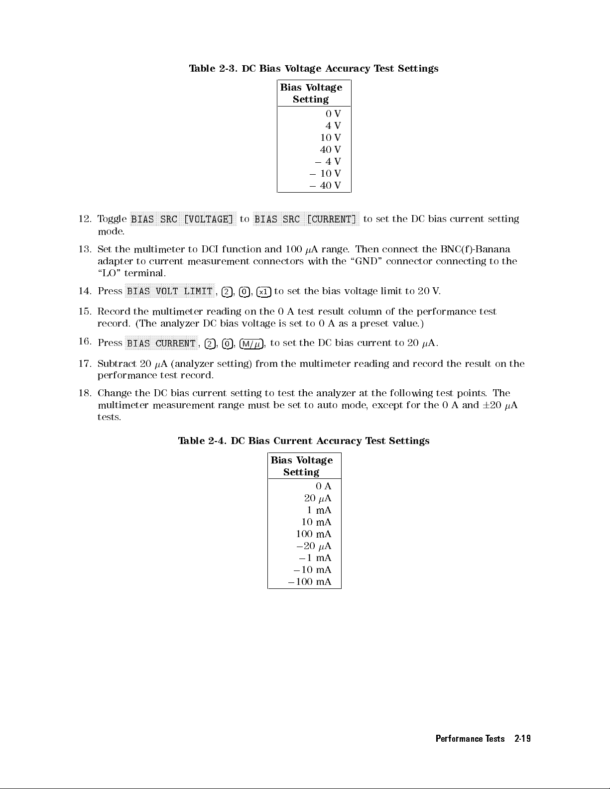
T
able 2-3.
DC Bias
Voltage
A
ccuracy
T
est
Settings
12. T
oggle
mode
13.
Set
the multimeter
adapter
\LO" terminal.
14.
Press
15.
Record
record. (The
16.
Press
17.
Subtract
performance
NN
NN
N
N
N
N
N
N
N
N
N
N
N
N
N
N
N
N
N
NN
NN
NN
NN
N
BIAS SRC
.
to
current measurement
N
N
N
N
N
N
N
N
NN
N
N
N
N
N
N
N
BIAS
VOLT
the
multimeter
N
N
N
N
N
N
N
N
N
N
N
N
N
N
N
N
NN
BIAS
CURRENT
20
N
[VOLTAGE]
N
N
N
N
N
N
N
N
N
N
N
N
N
N
N
N
LIMIT
analyzer DC
NN
N
N
N
N
N
N
N
N
N
N
N
N
N
A
(analyzer
test
record.
N
N
N
N
N
N
N
N
N
N
N
N
to DCI
NN
N
N
N
N
N
N
N
N
N
N
N
reading on
N
N
N
N
N
5
,
4
2
N
N
N
NN
NN
function and
N
,
4
bias
,
4
setting)
NN
NN
NN
N
N
to
connectors with
5
5
,
,
4
0
2
voltage
5
,
4
M/
0
Bias V
NN
N
N
N
N
N
N
N
N
N
N
N
N
N
N
N
N
,
5
to
100
to
is
set
the
N
set
Atest
set
BIAS SRC
4
x1
the 0
5
from
oltage
Setting
0
4
10
40
0
4
0
10
0
40
NN
NN
NN
NN
N
N
N
N
N
N
N
N
N
N
N
N
[CURRENT]
A
range
the
bias
result column
to
0
A
the
DC
multimeter
V
V
V
V
V
V
V
N
N
N
N
N
NN
NN
NN
NN
N
N
to
.
Then
the \GND"
voltage
as
a
preset
bias
current
reading
set
the
DC
bias
current
connect
connector connecting
limit
of
value
and
the
to
20
the
performance
.)
to
20
record
BNC(f)-Banana
V
.
A.
the
test
result
setting
to
the
on
the
18.
Change
multimeter
tests
the
DC
bias
current
measurement
.
T
able
range
2-4.
setting
must
DC
Bias
to
test
be
Current
Bias
Setting
the
set
to
V
oltage
20
1
10
100
020
0
1mA
0
10 mA
0
100 mA
analyzer
auto
mode
A
ccuracy
0
A
A
mA
mA
mA
A
at
,
T
the
following
except
est
Settings
for
the
test
0
points
A
and
.
The
6
20
A
Performance Tests 2-19
Page 50

PERFORMANCE TEST
RECORD
Agilent
Serial
T
echnologies
No
.
Frequency
Without
With
Option
Mainframe
T
est Station
Norm-T
Norm-T
High-T
emp
emp
emp
High-Temp
A
ccuracy
Option
Frequency
1D5
Frequency
4291B
High-Z
Low-Z
High-Z
Low-Z Head
1D5
1
GHz
1
GHz
RF Impedance/Material
Head
Head
Head
T
est
T
est
6
T
6
10.0
est
1.00
Limit
kHz
Limit
kHz
T
T
Analyzer
est
est
Result
Result
T
est
Date
T
emperature
Humidity %RH
T
ested
by:
Measurement
Uncertainty
kHz
6
2.3
kHz
Measurement
Uncertainty
kHz
6
0.19
kHz
C
Osc
Level
Norm-T
A
ccuracy
emp
High-Impedance
Osc
Level
0
19 dBm
0
13
dBm
0
7dBm
1dBm
7dBm
T
est
T
Frequency
1
MHz
10
MHz
100 MHz
1.8 GHz
1 GHz
est
Head
T
est
6
3.00
6
3.03
6
3.33 dB
6
8.00 dB
6
5.33 dB
Limit
dB
dB
T
est
Result
Measurement
Uncertainty
dB
dB
dB
dB
dB
6
0.18
6
0.19
6
0.20
6
0.19 dB
6
0.19 dB
dB
dB
dB
2-20 Performance Tests
Page 51

Norm-T
emp Low-Impedance
Test
Head (Option
012)
High-T
Osc Level
0
19 dBm
0
13
dBm
0
7
dBm
1
dBm
7
dBm
Frequency T
1 MHz
10
100
1.8
1
emp High-Impedance
Osc Level
0
19
dBm
0
19
dBm
0
19
dBm
0
19
dBm
0
19
dBm
0
19
dBm
0
19
dBm
0
19
dBm
Frequency T
1MHz
15
200
300
500
800
1.2
1.5
MHz
MHz
GHz
GHz
T
MHz
MHz
MHz
MHz
MHz
GHz
GHz
est
est
6
3.00
6
3.03
6
3.33
6
8.00 dB
6
5.33
Head
est
6
5.00
6
5.07
6
5.89
6
6.33
6
7.22
6
8.56
6
10.33
6
11.67
Limit
dB
dB
dB
dB
(Option
Limit
dB
dB
dB
dB
dB
dB
dB
dB
T
est
013)
T
est
Result
Result
Measurement
Uncertainty
dB
dB
dB
dB
dB
6
6
6
6
6
0.18
0.19
0.20
0.19
0.19
Measurement
Uncertainty
dB
dB
dB
dB
dB
dB
dB
dB
6
6
6
6
6
6
6
6
0.22
0.22
0.24
0.24
0.24
0.24
0.23
0.23
dB
dB
dB
dB
dB
dB
dB
dB
dB
dB
dB
dB
dB
0
13
dBm
0
7
dBm
0
7dBm
0
7
dBm
0
7
dBm
0
7dBm
0
7
dBm
0
7
dBm 500
0
7
dBm
0
7dBm
0
7dBm
0
7dBm
0
7dBm
10
10 MHz
15
100
200
300
800 MHz
1.2 GHz
1.5 GHz
1.8 GHz
1dBm
1dBm 1 GHz
MHz
1
MHz
MHz
MHz
MHz
MHz
MHz
1 GHz
1MHz
6
5.04
dB
6
4.00
dB
6
4.04
dB
6
4.07
dB
6
4.44 dB
6
4.89
dB
6
5.33
dB
6
6.22 dB
6
7.56
dB
6
8.44 dB
6
9.33 dB
6
10.67 dB
6
12.00 dB
6
4.00 dB
6
8.44 dB dB
dB
dB
dB
dB
dB
dB
dB
dB
dB
dB
dB
dB
dB
dB
6
0.22
6
0.22
6
0.22
6
0.22
6
0.24
6
0.24
6
0.24
6
0.24 dB
6
0.24
6
0.23 dB
6
0.23 dB
6
0.23 dB
6
0.23 dB
6
0.22 dB
6
0.23 dB
dB
dB
dB
dB
dB
dB
dB
dB
Performance Tests 2-21
Page 52

High-T
emp Low-Impedance
Test
Head (Option
014)
Osc Level
0
19 dBm
0
19
dBm
0
19
dBm
0
19
dBm
0
19
dBm
0
19
dBm
0
19 dBm
0
19
dBm
0
13
dBm
0
7
dBm
0
7
dBm
0
7
dBm
0
7
dBm
0
7
dBm
0
7
dBm
0
7
dBm
Frequency T
1 MHz
15
MHz
200
MHz
300 MHz
500
MHz
800
MHz
1.2 GHz
1.5
GHz
10
MHz
1
MHz
10
MHz
15
MHz
100
MHz
200
MHz
300
MHz
500
MHz
est
Limit
6
5.00
6
5.07
6
5.89
6
6.33
6
7.22
6
8.56
6
10.33
6
11.67 dB
6
5.04
6
4.00
6
4.04
6
4.07
6
4.44 dB
6
4.89
6
5.33
6
6.22
dB
dB
dB
dB
dB
dB
dB
dB
dB
dB
dB
dB
dB
dB
T
est
Result
Measurement
Uncertainty
dB
dB
dB
dB
dB
dB
dB
dB
dB
dB
dB
dB
dB
dB
dB
dB
6
6
6
6
6
6
6
6
6
6
6
6
6
6
6
6
0.22
0.22
0.24
0.24
0.24
0.24
0.23
0.23
0.22
0.22
0.22
0.22
0.24
0.24
0.24
0.24
dB
dB
dB
dB
dB
dB
dB
dB
dB
dB
dB
dB
dB
dB
dB
dB
0
7
0
7
0
7
0
7
0
7 dBm
1
1
dBm
dBm
dBm
dBm
dBm
dBm
800
MHz
1
GHz
1.2
GHz
1.5
GHz
1.8 GHz
1
MHz
1 GHz
6
6
6
6
10.67
6
12.00
6
6
7.56
8.44
9.33
4.00
8.44
dB
dB
dB
dB
dB
dB
dB
dB
dB
dB
dB
dB
dB
dB
6
0.24
6
0.23
6
0.23
6
0.23
6
0.23
6
0.22
6
0.23 dB
dB
dB
dB
dB
dB
dB
2-22 Performance Tests
Page 53

Measurement
A
ccuracy
T
est
Norm-T
T
est Head:
Standard:
Osc
Level:
Frequency
1
MHz
10
MHz
100 MHz
200
MHz
300
MHz
500 MHz
600
MHz
800
MHz
1
GHz
1.3
GHz
1.6
GHz
1.8
GHz
emp High-Impedance
Norm-T
Open
400
Measurement
P
arameter
j
j
j
j
j
j
j
j
j
j
j
j
mV
Y
Y
Y
Y
Y
Y
Y
Y
Y
Y
Y
Y
j
j
j
j
j
j
j
j
j
j
j
j
emp
High-Z
Test
Head
Calibration
V
alue
mS
mS
mS
mS
mS
mS
mS
mS
T
est
Limit T
S
6
2.12
S
S
6
3.24
S
S
6
14.4
S
S
6
28.4
S
6
41.8
S
6
69.1
S
6
97.6
S
6
130
S
6
164
S
6
259
S
6
329
S
6
379
S
est Result
Measurement
Uncertainty
S
6
0.03
S
6
0.34
S
6
3.4
S
6
6.7
S
6
10.0
S
6
16.7
S
6
21.3
S
6
S
6
S
6
S
6
S
6
28
35
46
63
71
S
S
S
S
S
S
S
S
S
S
S
S
T
est
Head:
Standard:
Osc
Level:
Frequency
1
MHz
10
MHz
100
MHz
200 MHz
300 MHz
500 MHz
600 MHz
800 MHz
1 GHz
1.3
GHz
1.6 GHz
1.8 GHz
Norm-T
Open
41
Measurement
P
arameter
mV
j
Y
j
Y
j
Y
j
Y
jYj
jYj
jYj
jYj
jYj
jYj
jYj
jYj
emp
j
j
j
j
High-Z
Calibration
V
alue
T
est
Limit
S
6
20.1
S
6
21.2
S
6
32.4
S
6
46.4
mS659.8S
mS687.1S
mS
6
111S
mS
6
143S
mS
6
177S
mS
6
272S
mS
6
342S
mS
6
392S
T
est
Result
S
S
S
S
Measurement
Uncertainty
S
6
0.03
S
6
0.34
S
6
3.4
S
6
6.7
S
6
10.0S
S
6
16.7S
S
621
S
628
S
635
S
646
S
663
S
671
S
S
S
S
S
S
S
S
S
S
Performance Tests 2-23
Page 54

T
est Head:
Standard:
Osc
Level: 400
Norm-Temp
Short
mV
High-Z
Frequency
1MHz
10
100
200
300
500
600
800
1.3
1.6
1.8
T
est
Head:
Standard:
Osc
Level:
1
MHz
MHz
MHz
MHz
MHz
MHz
MHz
GHz
GHz
GHz
GHz
Measurement
P
arameter
j
Z
j
j
Z
j
j
Z
j
j
Z
j
j
Z
j
j
Z
j
j
Z
j
j
Z
j
j
Z
j
j
Z
j
j
Z
j
j
Z
j
Norm-T
emp High-Z
Short
41
mV
Calibration
V
alue
0.00
m
0.00 m
0.00
m
0.00
m
0.00 m
0.00
m
0.00
m
0.00
m
0.00
m
0.00
m
0.00
m
0.00
m
T
est
6
101
6
105
6
150
6
200
6
250
6
350 m
6
400
6
500
6
600
6
750
6
900
6
Limit
1.00
m
m
m
m
m
m
m
m
m
m
T
est
Result
Measurement
Uncertainty
m
m
m
m
m
m
m
m
m
m
m
6
6
6
6
6
6
6
6
6
6
6
6
2
2
10
20
30
40
50
70
80
100
120
0.13
m
m
m
m
m
m
m
m
m
m
m
Frequency
1
MHz
10 MHz
100
MHz
200
MHz
300
MHz
500
MHz
600
MHz
800 MHz
1
GHz
1.3 GHz
1.6 GHz
1.8 GHz
Measurement
P
arameter
j
Z
j
j
Z
j
j
Z
j
j
Z
j
j
Z
j
j
Z
j
j
Z
j
jZj
jZj
jZj
jZj
jZj
Calibration
V
alue
0.00 m
0.00
m
0.00
m
0.00 m
0.00
m
0.00
m
0.00
m
0.00 m
0.00 m
0.00 m
0.00 m
0.00 m
T
est
6
101
6
105
6
150 m
6
200
6
250
6
350 m
6
400
6
500 m
6
600 m
6
750 m
6
900 m
6
Limit
m
m
m
m
m
1.00
T
est
Result
Measurement
Uncertainty
m
m
m
m
m
m
m
m
m
m
m
6
6
6
6
6
6
6
6
6
6
6
2
m
6
2
m
10
m
20
m
30
m
40 m
50
m
70 m
80 m
100 m
120 m
0.13
2-24 Performance Tests
Page 55

T
est Head:
Standard:
Osc
Level: 400
Norm-Temp
50
mV
High-Z
Frequency
1 MHz
1
MHz
10
MHz
10
MHz
100
MHz
100
MHz
200
MHz
200
MHz
300
MHz
300
MHz
500
MHz
500
MHz
600
MHz
600
MHz
800
MHz
800
MHz
Measurement
P
arameter
j
Z
j
j
Z
j
j
Z
j
j
Z
j
j
Z
j
j
Z
j
j
Z
j
j
Z
j
Calibration
V
alue
mrad
mrad
mrad
mrad
mrad
mrad
mrad
mrad
T
est
Limit
6
418
6
8.37
mrad
6
425
6
8.50
mrad
6
493
6
9.85
mrad
6
668
6
13.4
mrad
6
743
6
14.9
mrad
6
893
6
17.9
mrad
6
1.17
6
23.4 mrad
6
1.32
6
26.4
mrad
m
m
m
m
m
m
T
est
Result
m
mrad
m
mrad
m
mrad
m
mrad
m
mrad
m
mrad
mrad
mrad
Measurement
Uncertainty
6
90
m
6
1.80
mrad
6
90
m
6
1.80
mrad
6
100
m
6
2.00
mrad
6
125
m
6
2.5
mrad
6
150
m
6
3.0
mrad
6
200
m
6
4.0
mrad
6
0.25
6
5.0 mrad
6
0.25
6
5.0
mrad
1 GHz
1
GHz
1.3
GHz
1.3 GHz
1.6
GHz
1.6
GHz
1.8
GHz
1.8
GHz
j
Z
j
j
Z
j
j
Z
j
j
Z
j
mrad
mrad
mrad
mrad
6
6
6
6
6
1.47
29.4
6
2.09
41.9
6
2.32
46.4
6
2.47
49.4
mrad
mrad
mrad
mrad
mrad
mrad
mrad
mrad
6
0.25
6
5.0
mrad
6
0.25
6
5.0
mrad
6
0.25
6
5.0
mrad
6
0.25
6
5.0
mrad
Performance Tests 2-25
Page 56

T
est Head:
Standard:
Osc
Level: 41
Norm-Temp
50
mV
High-Z
Frequency
1
MHz
1
MHz
10
MHz
10
MHz
100
MHz
100
MHz
200
MHz
200
MHz
300
MHz
300
MHz
500
MHz
500
MHz
600
MHz
600
MHz
800
MHz
800
MHz
1
GHz
Measurement
P
arameter
j
Z
j
j
Z
j
j
Z
j
j
Z
j
j
Z
j
j
Z
j
j
Z
j
j
Z
j
j
Z
j
Calibration
V
alue
mrad
mrad
mrad
mrad
mrad
mrad
mrad
mrad
T
est
Limit
6
451
6
9.02
mrad
6
458
6
9.15
6
525
6
10.5
mrad
6
700
6
14.0
mrad
6
775
6
15.5
mrad
6
925 m
6
18.5
mrad
6
1.20
6
24.0 mrad
6
1.35
6
27.0
mrad
6
1.50
m
m
m
m
m
T
est
Result
m
mrad
m
mrad
m
mrad
m
mrad
m
mrad
m
mrad
mrad
mrad
Measurement
Uncertainty
6
90
m
6
1.80
mrad
6
90
m
6
1.80
mrad
6
100
m
6
2.0
mrad
6
125
m
6
2.5
mrad
6
150
m
6
3.0
mrad
6
200 m
6
4.0
mrad
6
0.25
6
5.0 mrad
6
0.25
6
5.0
mrad
6
0.25
1.3
1.3
1.6
1.6
1.8
1.8
1
GHz
GHz
GHz
GHz
GHz
GHz
GHz
j
Z
j
j
Z
j
j
Z
j
mrad
mrad
mrad
mrad
6
6
6
6
30.0
6
2.13
42.5
6
2.35
47.0
6
2.50
50.0
mrad
mrad
mrad
mrad
mrad
mrad
mrad
mrad
6
5.0
mrad
6
0.25
6
5.0
mrad
6
0.25
6
5.0
mrad
6
0.25
6
5.0
mrad
2-26 Performance Tests
Page 57

T
est Head:
Standard:
Osc
Level: 400
Norm-Temp
10 cm
Airline with
mV
High-Z
Open
Frequency
1 MHz
1
MHz
10
MHz
10
MHz
100
MHz
100
MHz
200
MHz
200
MHz
300
MHz
300
MHz
500
MHz
500
MHz
600
MHz
600
MHz
800
MHz
800
MHz
Measurement
P
arameter
j
Z
j
j
Z
j
j
Z
j
j
Z
j
j
Z
j
j
Z
j
j
Z
j
j
Z
j
Calibration
V
alue
k
rad
k
rad
rad
rad
rad
rad
rad
rad
T
est
Limit
6
1.13
6
51.8
mrad
6
27.5
6
12.6
mrad
6
2.22
6
10.3
mrad
6
1.29
6
12.7
mrad
6
874
6
14.4
mrad
6
559
6
24.8
mrad
6
524
6
53.4 mrad
6
679
6
50.0
mrad
k
m
m
m
m
T
est
Result
k
mrad
mrad
mrad
mrad
m
mrad
m
mrad
m
mrad
m
mrad
Measurement
Uncertainty
6
0.04
k
6
2.0
mrad
6
4.4
6
2.0
mrad
6
0.43
6
2.0
mrad
6
0.25
6
2.5
mrad
6
182
m
6
3.0
mrad
6
90
m
6
4.0
mrad
6
88
m
6
9.0 mrad
6
122
m
6
9.0
mrad
1 GHz
1
GHz
1.6
GHz
1.6 GHz
1.8
GHz
1.8
GHz
j
Z
j
j
Z
j
j
Z
j
rad
rad
rad
6
6
6
6
1.34
30.3
6
3.84
44.8
6
1.87
56.4
mrad
mrad
mrad
mrad
mrad
mrad
6
6
6
6
0.27
6.0
6
0.86
10.0
6
0.33
10.0
mrad
mrad
mrad
Performance Tests 2-27
Page 58

T
est Head:
Standard:
Osc
Level: 41
Norm-Temp
10 cm
Airline with
mV
High-Z
Open
Frequency
1
MHz
1
MHz
10
MHz
10
MHz
100
MHz
100
MHz
200
MHz
200
MHz
300
MHz
300
MHz
500
MHz
500
MHz
600
MHz
600
MHz
800
MHz
800
MHz
1
GHz
Measurement
P
arameter
j
Z
j
j
Z
j
j
Z
j
j
Z
j
j
Z
j
j
Z
j
j
Z
j
j
Z
j
j
Z
j
Calibration
V
alue
k
rad
k
rad
rad
rad
rad
rad
rad
rad
T
est
Limit
6
9.69
6
444
mrad
6
113
6
51.8
6
2.81
6
13.1
mrad
6
1.42
6
14.0
mrad
6
922
6
15.2
mrad
6
566 m
6
25.1
mrad
6
525
6
53.6 mrad
6
682
6
50.2
mrad
6
1.37
k
m
m
m
T
est
Result
k
mrad
mrad
mrad
mrad
m
mrad
m
mrad
m
mrad
m
mrad
Measurement
Uncertainty
6
0.04
k
6
2
mrad
6
4
6
2.0
mrad
6
0.43
6
2.0
mrad
6
0.25
6
2.5
mrad
6
182
m
6
3.0
mrad
6
90 m
6
4.0
mrad
6
88
m
6
9.0 mrad
6
122
m
6
9.0
mrad
6
0.27
1.6
1.6
1.8
1.8
1
GHz
GHz
GHz
GHz
GHz
rad
rad
rad
6
6
6
30.9
6
3.94
45.9
6
1.88
56.9
mrad
mrad
mrad
j
Z
j
j
Z
j
mrad
mrad
mrad
6
6
6
6.0
6
0.86
10.0
6
0.33
10.0
mrad
mrad
mrad
2-28 Performance Tests
Page 59

T
est Head:
Standard:
Osc
Level: 400
Norm-Temp
10 cm
Airline with
mV
High-Z
Short
Frequency
1 MHz
1
MHz
10
MHz
10
MHz
100
MHz
100
MHz
200
MHz
200
MHz
300
MHz
300
MHz
500
MHz
500
MHz
600
MHz
600
MHz
1
GHz
1
GHz
Measurement
P
arameter
j
Z
j
j
Z
j
j
Z
j
j
Z
j
j
Z
j
j
Z
j
j
Z
j
j
Z
j
Calibration
V
alue
m
rad
rad
rad
rad
rad
rad
rad
rad
T
est
Limit
6
101
6
893
mrad
6
111
6
104
mrad
6
216
6
20.2
mrad
6
393
6
17.5
mrad
6
592
6
16.2
mrad
6
1.48
6
17.0
mrad
6
3.88
6
25.0 mrad
6
2.43
6
28.2
mrad
m
m
m
m
m
T
est
Result
m
mrad
m
mrad
m
mrad
m
mrad
m
mrad
mrad
mrad
mrad
Measurement
Uncertainty
6
2
m
6
15
mrad
6
4
m
6
4
mrad
6
27
m
6
2.5
mrad
6
67
m
6
3.0
mrad
6
110
m
6
3.0
mrad
6
0.31
6
3.5
mrad
6
0.78
6
5.0 mrad
6
0.52
6
6.0
mrad
1.3 GHz
1.3
GHz
1.6
GHz
1.6 GHz
1.8
GHz
1.8
GHz
j
Z
j
j
Z
j
j
Z
j
rad
rad
rad
6
1.26
6
57.0
6
1.14
6
105
6
1.98
6
54.1mrad
mrad
mrad
mrad
mrad
mrad
6
6
6
10.0
6
6
15
6
10.0
0.22
0.16
mrad
0.37
mrad
mrad
Performance Tests 2-29
Page 60

T
est Head:
Standard:
Osc
Level: 41
Norm-Temp
10 cm
Airline with
mV
High-Z
Short
Frequency
1
MHz
1
MHz
10
MHz
10
MHz
100
MHz
100
MHz
200
MHz
200
MHz
300
MHz
300
MHz
500
MHz
500
MHz
600
MHz
600
MHz
1
GHz
1
GHz
1.3
GHz
Measurement
P
arameter
j
Z
j
j
Z
j
j
Z
j
j
Z
j
j
Z
j
j
Z
j
j
Z
j
j
Z
j
j
Z
j
Calibration
V
alue
m
rad
rad
rad
rad
rad
rad
rad
rad
T
est
Limit
6
101
6
893
mrad
6
111
6
104
6
218
6
20.3
mrad
6
399
6
17.8
mrad
6
609
6
16.7
mrad
6
1.58
6
18.1
mrad
6
4.19
6
27.0 mrad
6
2.52
6
29.3
mrad
6
1.26
m
m
m
m
m
T
est
Result
m
rad
m
mrad
m
mrad
m
mrad
m
mrad
mrad
mrad
mrad
Measurement
Uncertainty
6
2
m
6
15
mrad
6
4
m
6
4
mrad
6
27
m
6
2.5
mrad
6
67
m
6
3.0
mrad
6
110
m
6
3.0
mrad
6
0.31
6
3.5
mrad
6
0.78
6
5.0 mrad
6
0.52
6
6.0
mrad
6
0.22
1.3
1.6
1.6
1.8
1.8
GHz
GHz
GHz
GHz
GHz
rad
rad
rad
6
57.3
6
1.14
6
105
6
2.00
6
54.6mrad
mrad
mrad
j
Z
j
j
Z
j
mrad
mrad
mrad
6
6
10.0
6
6
15
6
10.0
0.16
mrad
0.37
mrad
mrad
2-30 Performance Tests
Page 61

Norm-T
T
est Head:
Standard:
Osc
emp Low-Impedance
Level: 400
Norm-T
Open
mV
emp
Test
Low-Z
Head (Option
012)
Frequency Measurement
Parameter
1
MHz
10
MHz
100 MHz
200
MHz
300
MHz
500 MHz
600
MHz
800
MHz
1
GHz
1.3
GHz
1.6
GHz
1.8
GHz
T
est
Head:
Standard:
Osc
Level:
j
Y
j
j
Y
j
j
Y
j
j
Y
j
j
Y
j
j
Y
j
j
Y
j
j
Y
j
j
Y
j
j
Y
j
j
Y
j
j
Y
j
Norm-T
Open
41
mV
emp
Calibration
Low-Z
Value
mS
mS
mS
mS
mS
mS
mS
mS
S
S
S
S
Test
6
30.1
6
31.2
6
42.4
6
56.4
6
69.7
6
96.8
6
6
6
6
6
6
120
152
185
280
349
398
Limit T
S
S
S
S
S
S
S
S
S
S
S
S
est Result
Measurement
Uncertainty
S
6
0.0
S
6
0.3
S
6
3.4
S
6
6.7
S
6
10.0
S
6
16.7
S
6
S
6
S
6
S
6
S
6
S
6
21
28
35
46
63
71
S
S
S
S
S
S
S
S
S
S
S
S
Frequency
1
MHz
10
MHz
100
MHz
200 MHz
300
MHz
500
MHz
600 MHz
800 MHz
1 GHz
1.3 GHz
1.6 GHz
1.8 GHz
Measurement
P
arameter
j
Y
j
j
Y
j
j
Y
j
j
Y
j
j
Y
j
j
Y
j
j
Y
j
jYj
jYj
jYj
jYj
jYj
Calibration
V
alue
mS
mS
mS
mS
mS
mS
mS
mS
T
est
Limit
S
6
30.1
S
6
31.2
S
6
42.4
S
6
56.4
6
69.7
6
96.9
6
120
6
152S
6
186S
6
281S
6
350S
6
399S
T
est
Result
S
S
S
S
S
S
S
Measurement
Uncertainty
S
6
0.0
S
6
0.3
S
6
3.4
S
6
6.7
S
6
10.0
S
6
16.7
S
6
S
628
S
635
S
646
S
663
S
671
21
S
S
S
S
S
S
S
S
S
S
S
S
Performance Tests 2-31
Page 62

T
est Head:
Standard:
Osc
Level: 400
Norm-Temp
Short
mV
Low-Z
Frequency
1MHz
10
100
200
300
500
600
800
1.3
1.6
1.8
T
est
Head:
Standard:
Osc
Level:
1
MHz
MHz
MHz
MHz
MHz
MHz
MHz
GHz
GHz
GHz
GHz
Measurement
P
arameter
j
Z
j
j
Z
j
j
Z
j
j
Z
j
j
Z
j
j
Z
j
j
Z
j
j
Z
j
j
Z
j
j
Z
j
j
Z
j
j
Z
j
Norm-T
emp Low-Z
Short
41
mV
Calibration
V
alue
0.00
m
0.00 m
0.00
m
0.00
m
0.00 m
0.00
m
0.00
m
0.00
m
0.00
m
0.00
m
0.00
m
0.00
m
T
est
6
10.5
6
15.0
6
60.0
6
110
6
160
6
260 m
6
310
6
410
6
510
6
660
6
810
6
910
Limit
m
m
m
m
m
m
m
m
m
m
m
T
est
Result
Measurement
Uncertainty
m
m
m
m
m
m
m
m
m
m
m
m
6
6
6
6
6
6
6
6
6
6
6
6
1.8
2.0
10.0
20
30
40
50
70
80
100
120
130
m
m
m
m
m
m
m
m
m
m
m
m
Frequency
1
MHz
10 MHz
100
MHz
200
MHz
300
MHz
500
MHz
600
MHz
800 MHz
1
GHz
1.3 GHz
1.6 GHz
1.8 GHz
Measurement
P
arameter
j
Z
j
j
Z
j
j
Z
j
j
Z
j
j
Z
j
j
Z
j
j
Z
j
jZj
jZj
jZj
jZj
jZj
Calibration
V
alue
0.00 m
0.00
m
0.00
m
0.00 m
0.00
m
0.00
m
0.00
m
0.00 m
0.00 m
0.00 m
0.00 m
0.00 m
T
est
6
50.5
6
55.0
6
100 m
6
150
6
200
6
300 m
6
350
6
450 m
6
550 m
6
700 m
6
850 m
6
950 m
Limit
m
m
m
m
m
T
est
Result
Measurement
Uncertainty
m
m
m
m
m
m
m
m
m
m
m
m
6
6
6
6
6
6
6
6
6
6
6
6
1.8
m
2.0
m
10
m
20
m
30
m
40 m
50
m
70 m
80 m
100 m
120 m
130 m
2-32 Performance Tests
Page 63

T
est Head:
Standard:
Osc
Level: 400
Norm-Temp
50
mV
Low-Z
Frequency
1 MHz
1
MHz
10
MHz
10
MHz
100
MHz
100
MHz
200
MHz
200
MHz
300
MHz
300
MHz
500
MHz
500
MHz
600
MHz
600
MHz
800
MHz
800
MHz
Measurement
P
arameter
j
Z
j
j
Z
j
j
Z
j
j
Z
j
j
Z
j
j
Z
j
j
Z
j
j
Z
j
Calibration
V
alue
mrad
mrad
mrad
mrad
mrad
mrad
mrad
mrad
T
est
Limit
6
396
6
7.92
mrad
6
403
6
8.05
mrad
6
470
6
9.40
mrad
6
645
6
12.9
mrad
6
720
6
14.4
mrad
6
870
6
17.4
mrad
6
1.15
6
22.9 mrad
6
1.30
6
25.9
mrad
m
m
m
m
m
m
T
est
Result
m
mrad
m
mrad
m
mrad
m
mrad
m
mrad
m
mrad
mrad
mrad
Measurement
Uncertainty
6
90
m
6
1.80
mrad
6
90
m
6
1.80
mrad
6
100
m
6
2.00
mrad
6
125
m
6
2.5
mrad
6
150
m
6
3.0
mrad
6
200
m
6
4.0
mrad
6
0.25
6
5.0 mrad
6
0.25
6
5.0
mrad
1 GHz
1
GHz
1.3
GHz
1.3 GHz
1.6
GHz
1.6
GHz
1.8
GHz
1.8
GHz
j
Z
j
j
Z
j
j
Z
j
j
Z
j
mrad
mrad
mrad
mrad
6
6
6
6
6
1.45
28.9
6
2.07
41.4
6
2.30
45.9
6
2.45
48.9
mrad
mrad
mrad
mrad
mrad
mrad
mrad
mrad
6
0.25
6
5.0
mrad
6
0.25
6
5.0
mrad
6
0.25
6
5.0
mrad
6
0.25
6
5.0
mrad
Performance Tests 2-33
Page 64

T
est Head:
Standard:
Osc
Level: 41
Norm-Temp
50
mV
Low-Z
Frequency
1
MHz
1
MHz
10
MHz
10
MHz
100
MHz
100
MHz
200
MHz
200
MHz
300
MHz
300
MHz
500
MHz
500
MHz
600
MHz
600
MHz
800
MHz
800
MHz
1
GHz
Measurement
P
arameter
j
Z
j
j
Z
j
j
Z
j
j
Z
j
j
Z
j
j
Z
j
j
Z
j
j
Z
j
j
Z
j
Calibration
V
alue
mrad
mrad
mrad
mrad
mrad
mrad
mrad
mrad
T
est
Limit
6
426
6
8.52
mrad
6
433
6
8.65
6
500
6
10.0
mrad
6
675
6
13.5
mrad
6
750
6
15.0
mrad
6
900 m
6
18.0
mrad
6
1.18
6
23.5 mrad
6
1.33
6
26.5
mrad
6
1.48
m
m
m
m
m
T
est
Result
m
mrad
m
mrad
m
mrad
m
mrad
m
mrad
m
mrad
mrad
mrad
Measurement
Uncertainty
6
90
m
6
1.80
mrad
6
90
m
6
1.80
mrad
6
100
m
6
2.0
mrad
6
125
m
6
2.5
mrad
6
150
m
6
3.0
mrad
6
200 m
6
4.0
mrad
6
0.25
6
5.0 mrad
6
0.25
6
5.0
mrad
6
0.25
1.3
1.3
1.6
1.6
1.8
1.8
1
GHz
GHz
GHz
GHz
GHz
GHz
GHz
j
Z
j
j
Z
j
j
Z
j
mrad
mrad
mrad
mrad
6
6
6
6
29.5
6
2.10
42.0
6
2.33
46.5
6
2.48
49.5
mrad
mrad
mrad
mrad
mrad
mrad
mrad
mrad
6
5.0
mrad
6
0.25
6
5.0
mrad
6
0.25
6
5.0
mrad
6
0.25
6
5.0
mrad
2-34 Performance Tests
Page 65

T
est Head:
Standard:
Osc
Level: 400
Norm-Temp
10 cm
Airline with
mV
Low-Z
Open
Frequency
1 MHz
1
MHz
10
MHz
10
MHz
100
MHz
100
MHz
200
MHz
200
MHz
300
MHz
300
MHz
500
MHz
500
MHz
600
MHz
600
MHz
800
MHz
800
MHz
Measurement
P
arameter
j
Z
j
j
Z
j
j
Z
j
j
Z
j
j
Z
j
j
Z
j
j
Z
j
j
Z
j
Calibration
V
alue
k
rad
k
rad
rad
rad
rad
rad
rad
rad
T
est
Limit
6
14.4
6
662
mrad
6
161
6
73.6
mrad
6
3.19
6
14.9
mrad
6
1.44
6
14.2
mrad
6
879
6
14.4
mrad
6
491
6
21.8
mrad
6
446
6
45.5 mrad
6
603
6
44.4
mrad
k
m
m
m
m
T
est
Result
k
mrad
mrad
mrad
mrad
m
mrad
m
mrad
m
mrad
m
mrad
Measurement
Uncertainty
6
0.0
k
6
2
mrad
6
4
6
2.0
mrad
6
0.43
6
2.0
mrad
6
0.25
6
2.5
mrad
6
182
m
6
3.0
mrad
6
90
m
6
4.0
mrad
6
88
m
6
9.0 mrad
6
122
m
6
9.0
mrad
1 GHz
1
GHz
1.6
GHz
1.6 GHz
1.8
GHz
1.8
GHz
j
Z
j
j
Z
j
j
Z
j
rad
rad
rad
6
6
6
6
1.31
29.5
6
3.93
45.9
6
1.81
54.8
mrad
mrad
mrad
mrad
mrad
mrad
6
6
6
6
0.27
6.0
6
0.86
10.0
6
0.33
10.0
mrad
mrad
mrad
Performance Tests 2-35
Page 66

T
est Head:
Standard:
Osc
Level: 41
Norm-Temp
10 cm
Airline with
mV
Low-Z
Open
Frequency
1
MHz
1
MHz
10
MHz
10
MHz
100
MHz
100
MHz
200
MHz
200
MHz
300
MHz
300
MHz
500
MHz
500
MHz
600
MHz
600
MHz
800
MHz
800
MHz
1
GHz
Measurement
P
arameter
j
Z
j
j
Z
j
j
Z
j
j
Z
j
j
Z
j
j
Z
j
j
Z
j
j
Z
j
j
Z
j
Calibration
V
alue
k
rad
k
rad
rad
rad
rad
rad
rad
rad
T
est
Limit
6
14.4
6
662
mrad
6
161
6
73.6
6
3.22
6
15.0
mrad
6
1.47
6
14.5
mrad
6
909
6
14.9
mrad
6
521 m
6
23.1
mrad
6
476
6
48.6 mrad
6
633
6
46.6
mrad
6
1.34
k
m
m
m
T
est
Result
k
mrad
mrad
mrad
mrad
m
mrad
m
mrad
m
mrad
m
mrad
Measurement
Uncertainty
6
0.0
k
6
2
mrad
6
4
6
2.0
mrad
6
0.43
6
2.0
mrad
6
0.25
6
2.5
mrad
6
182
m
6
3.0
mrad
6
90 m
6
4.0
mrad
6
88
m
6
9.0 mrad
6
122
m
6
9.0
mrad
6
0.27
1.6
1.6
1.8
1.8
1
GHz
GHz
GHz
GHz
GHz
rad
rad
rad
6
6
6
30.2
6
3.96
46.2
6
1.84
55.7
mrad
mrad
mrad
j
Z
j
j
Z
j
mrad
mrad
mrad
6
6
6
6.0
6
0.86
10.0
6
0.33
10.0
mrad
mrad
mrad
2-36 Performance Tests
Page 67

T
est Head:
Standard:
Osc
Level: 400
Norm-Temp
10 cm
Airline with
mV
Low-Z
Short
Frequency
1 MHz
1
MHz
10
MHz
10
MHz
100
MHz
100
MHz
200
MHz
200
MHz
300
MHz
300
MHz
500
MHz
500
MHz
600
MHz
600
MHz
1
GHz
1
GHz
Measurement
P
arameter
j
Z
j
j
Z
j
j
Z
j
j
Z
j
j
Z
j
j
Z
j
j
Z
j
j
Z
j
Calibration
V
alue
m
rad
rad
rad
rad
rad
rad
rad
rad
T
est
Limit
6
11.2
6
98.7
mrad
6
21.5
6
20.0
mrad
6
139
6
13.0
mrad
6
324
6
14.5
mrad
6
542
6
14.8
mrad
6
1.58
6
18.1
mrad
6
4.35
6
28.0 mrad
6
2.52
6
29.2
mrad
m
m
m
m
m
T
est
Result
m
mrad
m
mrad
m
mrad
m
mrad
m
mrad
mrad
mrad
mrad
Measurement
Uncertainty
6
1.7
m
6
15.0
mrad
6
4.3
m
6
4.0
mrad
6
27
m
6
2.5
mrad
6
67
m
6
3.0
mrad
6
110
m
6
3.0
mrad
6
0.31
6
3.5
mrad
6
0.78
6
5.0 mrad
6
0.52
6
6.0
mrad
1.3 GHz
1.3
GHz
1.6
GHz
1.6 GHz
1.8
GHz
1.8
GHz
j
Z
j
j
Z
j
j
Z
j
rad
rad
rad
6
1.19
6
53.9
6
1.06
6
97.8
6
1.94
6
52.8mrad
mrad
mrad
mrad
mrad
mrad
6
6
6
6
0.22
10.0
6
0.16
15.0
6
0.37
10.0
mrad
mrad
mrad
Performance Tests 2-37
Page 68

T
est Head:
Standard:
Osc
Level: 41
Norm-Temp
10 cm
Airline with
mV
Low-Z
Short
Frequency
1
MHz
1
MHz
10
MHz
10
MHz
100
MHz
100
MHz
200
MHz
200
MHz
300
MHz
300
MHz
500
MHz
500
MHz
600
MHz
600
MHz
1
GHz
1
GHz
1.3
GHz
Measurement
P
arameter
j
Z
j
j
Z
j
j
Z
j
j
Z
j
j
Z
j
j
Z
j
j
Z
j
j
Z
j
j
Z
j
Calibration
V
alue
m
rad
rad
rad
rad
rad
rad
rad
rad
T
est
Limit
6
51.2
6
452
mrad
6
61.5
6
57.3
6
169
6
15.8
mrad
6
354
6
15.8
mrad
6
572
6
15.7
mrad
6
1.61
6
18.4
mrad
6
4.38
6
28.2 mrad
6
2.55
6
29.6
mrad
6
1.22
m
m
m
m
m
T
est
Result
m
mrad
m
mrad
m
mrad
m
mrad
m
mrad
mrad
mrad
mrad
Measurement
Uncertainty
6
1.7
m
6
15
mrad
6
4.3
m
6
4.0
mrad
6
27
m
6
2.5
mrad
6
67
m
6
3.0
mrad
6
110
m
6
3.0
mrad
6
0.31
6
3.5
mrad
6
0.78
6
5.0 mrad
6
0.52
6
6.0
mrad
6
0.22
1.3
1.6
1.6
1.8
1.8
GHz
GHz
GHz
GHz
GHz
rad
rad
rad
6
55.2
6
1.09
6
101
6
1.97
6
53.6mrad
mrad
mrad
j
Z
j
j
Z
j
mrad
mrad
mrad
6
6
10.0
6
6
15
6
10.0
0.16
mrad
0.37
mrad
mrad
2-38 Performance Tests
Page 69
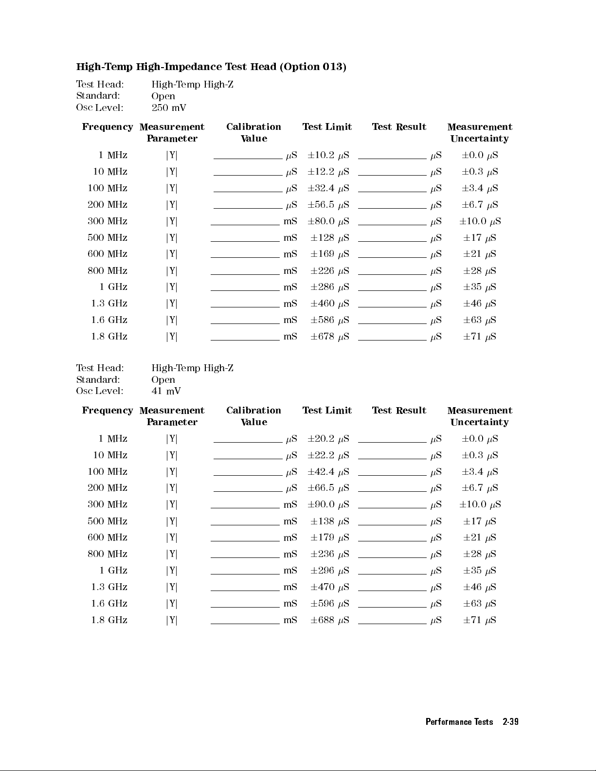
High-T
T
Standard:
Osc
emp High-Impedance
est Head:
Level: 250
High-T
Open
mV
emp
Test
High-Z
Head (Option
013)
Frequency Measurement
Parameter
1
MHz
10
MHz
100 MHz
200
MHz
300
MHz
500 MHz
600
MHz
800
MHz
1
GHz
1.3
GHz
1.6
GHz
1.8
GHz
T
est
Head:
Standard:
Osc
Level:
j
Y
j
Y
j
Y
j
Y
j
Y
j
Y
j
Y
j
Y
j
Y
j
Y
j
Y
j
Y
High-T
Open
41
mV
j
j
j
j
j
j
j
j
j
j
j
j
emp
Calibration
High-Z
Value
mS
mS
mS
mS
mS
mS
mS
mS
S
S
S
S
Test
6
10.2
6
12.2
6
32.4
6
56.5
6
80.0
6
6
6
6
6
6
6
128
169
226
286
460
586
678
Limit T
S
S
S
S
S
S
S
S
S
S
S
S
est Result
Measurement
Uncertainty
S
6
0.0
S
6
0.3
S
6
3.4
S
6
6.7
S
6
10.0
S
6
S
6
S
6
S
6
S
6
S
6
S
6
17
21
28
35
46
63
71
S
S
S
S
S
S
S
S
S
S
S
S
Frequency
1
MHz
10
MHz
100
MHz
200 MHz
300
MHz
500
MHz
600 MHz
800 MHz
1 GHz
1.3 GHz
1.6 GHz
1.8 GHz
Measurement
P
arameter
j
Y
j
j
Y
j
j
Y
j
j
Y
j
j
Y
j
j
Y
j
j
Y
j
jYj
jYj
jYj
jYj
jYj
Calibration
V
alue
mS
mS
mS
mS
mS
mS
mS
mS
T
est
Limit
S
6
20.2
S
6
22.2
S
6
42.4
S
6
66.5
6
90.0
6
138
6
179
6
236S
6
296S
6
470S
6
596S
6
688S
T
est
Result
S
S
S
S
S
S
S
Measurement
Uncertainty
S
6
0.0
S
6
0.3
S
6
3.4
S
6
6.7
S
6
10.0
S
6
S
6
S
628
S
635
S
646
S
663
S
671
17
21
S
S
S
S
S
S
S
S
S
S
S
S
Performance Tests 2-39
Page 70

T
est Head:
Standard:
Osc
Level: 250
High-Temp
Short
mV
High-Z
Frequency
1MHz
10
100
200
300
500
600
800
1.3
1.6
1.8
T
est
Head:
Standard:
Osc
Level:
1
MHz
MHz
MHz
MHz
MHz
MHz
MHz
GHz
GHz
GHz
GHz
Measurement
P
arameter
j
Z
j
j
Z
j
j
Z
j
j
Z
j
j
Z
j
j
Z
j
j
Z
j
j
Z
j
j
Z
j
j
Z
j
j
Z
j
j
Z
j
High-T
emp High-Z
Short
41
mV
Calibration
V
alue
0.00
m
0.00 m
0.00
m
0.00
m
0.00 m
0.00
m
0.00
m
0.00
m
0.00
m
0.00
m
0.00
m
0.00
m
T
est
6
101
6
110
6
200
6
300
6
400
6
600 m
6
700
6
900
6
6
6
6
Limit
1.10
1.40
1.70
1.90
m
m
m
m
m
m
m
T
est
Result
Measurement
Uncertainty
m
m
m
m
m
m
m
m
m
m
m
6
6
6
6
6
6
6
6
6
6
6
6
2
m
2
m
10
20
30
40
50
70
0.08
0.10
0.12
0.13
m
m
m
m
m
m
Frequency
1
MHz
10 MHz
100
MHz
200
MHz
300
MHz
500
MHz
600
MHz
800 MHz
1
GHz
1.3 GHz
1.6 GHz
1.8 GHz
Measurement
P
arameter
j
Z
j
j
Z
j
j
Z
j
j
Z
j
j
Z
j
j
Z
j
j
Z
j
jZj
jZj
jZj
jZj
jZj
Calibration
V
alue
0.00 m
0.00
m
0.00
m
0.00 m
0.00
m
0.00
m
0.00
m
0.00 m
0.00 m
0.00 m
0.00 m
0.00 m
T
est
6
101
6
110
6
200 m
6
300
6
400
6
600 m
6
700
6
900 m
6
6
6
6
Limit
m
m
m
m
m
1.10
1.40
1.70
1.90
T
est
Result
Measurement
Uncertainty
m
m
m
m
m
m
m
m
m
m
m
6
6
6
6
6
6
6
6
6
6
6
2
6
2
10
20
30
40 m
50
70 m
0.08
0.10
0.12
0.13
m
m
m
m
m
m
2-40 Performance Tests
Page 71

T
est Head:
Standard:
Osc
Level: 250
High-Temp
50
mV
High-Z
Frequency
1 MHz
1
MHz
10
MHz
10
MHz
100
MHz
100
MHz
200
MHz
200
MHz
300
MHz
300
MHz
500
MHz
500
MHz
600
MHz
600
MHz
800
MHz
800
MHz
Measurement
P
arameter
j
Z
j
j
Z
j
j
Z
j
j
Z
j
j
Z
j
j
Z
j
j
Z
j
j
Z
j
Calibration
V
alue
mrad
mrad
mrad
mrad
mrad
mrad
mrad
mrad
T
est
Limit
6
427
6
8.53
mrad
6
440
6
8.80
mrad
6
575
6
11.5
mrad
6
825
6
16.5
mrad
6
975
6
19.5
mrad
6
1.28
6
25.5
mrad
6
1.78
6
35.5 mrad
6
2.08
6
41.5
mrad
m
m
m
m
m
T
est
Result
m
mrad
m
mrad
m
mrad
m
mrad
m
mrad
m
mrad
mrad
mrad
Measurement
Uncertainty
6
90
m
6
1.80
mrad
6
90
m
6
1.80
mrad
6
100
m
6
2.0
mrad
6
125
m
6
2.5
mrad
6
150
m
6
3.0
mrad
6
0.20
6
4.0
mrad
6
0.25
6
5.0 mrad
6
0.25
6
5.0
mrad
1 GHz
1
GHz
1.3
GHz
1.3 GHz
1.6
GHz
1.6
GHz
1.8
GHz
1.8
GHz
j
Z
j
j
Z
j
j
Z
j
j
Z
j
mrad
mrad
mrad
mrad
6
6
6
6
6
2.38
47.5
6
3.58
71.5
6
4.03
80.5
6
4.33
86.5
mrad
mrad
mrad
mrad
mrad
mrad
mrad
mrad
6
0.25
6
5.0
mrad
6
0.25
6
5.0
mrad
6
0.25
6
5.0
mrad
6
0.25
6
5.0
mrad
Performance Tests 2-41
Page 72

T
est Head:
Standard:
Osc
Level: 41
High-Temp
50
mV
High-Z
Frequency
1
MHz
1
MHz
10
MHz
10
MHz
100
MHz
100
MHz
200
MHz
200
MHz
300
MHz
300
MHz
500
MHz
500
MHz
600
MHz
600
MHz
800
MHz
800
MHz
1
GHz
Measurement
P
arameter
j
Z
j
j
Z
j
j
Z
j
j
Z
j
j
Z
j
j
Z
j
j
Z
j
j
Z
j
j
Z
j
Calibration
V
alue
mrad
mrad
mrad
mrad
mrad
mrad
mrad
mrad
T
est
Limit
6
452
6
9.03
mrad
6
465
6
9.30
6
600
6
12.0
mrad
6
850
6
17.0
mrad
6
1.00
6
20.0
mrad
6
1.30
6
26.0
mrad
6
1.80
6
36.0 mrad
6
2.10
6
42.0
mrad
6
2.40
m
m
m
m
T
est
Result
m
mrad
m
mrad
m
mrad
m
mrad
m
mrad
m
mrad
mrad
mrad
Measurement
Uncertainty
6
90
m
6
1.80
mrad
6
90
m
6
1.80
mrad
6
100
m
6
2.0
mrad
6
125
m
6
2.5
mrad
6
0.15
6
3.0
mrad
6
0.20
6
4.0
mrad
6
0.25
6
5.0 mrad
6
0.25
6
5.0
mrad
6
0.25
1.3
1.3
1.6
1.6
1.8
1.8
1
GHz
GHz
GHz
GHz
GHz
GHz
GHz
j
Z
j
j
Z
j
j
Z
j
mrad
mrad
mrad
mrad
6
6
6
6
48.0
6
3.60
72.0
6
4.05
81.0
6
4.35
87.0
mrad
mrad
mrad
mrad
mrad
mrad
mrad
mrad
6
5.0
mrad
6
0.25
6
5.0
mrad
6
0.25
6
5.0
mrad
6
0.25
6
5.0
mrad
2-42 Performance Tests
Page 73

T
est Head:
Standard:
Osc
Level: 250
High-Temp
10 cm
Airline with
mV
High-Z
Open
Frequency
1 MHz
1
MHz
10
MHz
10
MHz
100
MHz
100
MHz
200
MHz
200
MHz
300
MHz
300
MHz
500
MHz
500
MHz
600
MHz
600
MHz
800
MHz
800
MHz
Measurement
P
arameter
j
Z
j
j
Z
j
j
Z
j
j
Z
j
j
Z
j
j
Z
j
j
Z
j
j
Z
j
Calibration
V
alue
k
rad
k
rad
rad
rad
rad
rad
rad
rad
T
est
Limit
6
4.98
6
228
mrad
6
70.3
6
32.2
mrad
6
2.86
6
13.4
mrad
6
1.62
6
16.0
mrad
6
1.15
6
18.8
mrad
6
836
6
37.1
mrad
6
860
6
87.6 mrad
6
1.14
6
83.5
mrad
k
m
m
T
est
Result
k
mrad
mrad
mrad
mrad
m
mrad
m
mrad
m
mrad
m
mrad
Measurement
Uncertainty
6
0.04
k
6
2
mrad
6
4.4
6
2.0
mrad
6
0.43
6
2.0
mrad
6
0.25
6
2.5
mrad
6
0.18
6
3.0
mrad
6
90
m
6
4.0
mrad
6
88
m
6
9.0 mrad
6
0.12
6
9.0
mrad
1 GHz
1
GHz
1.6
GHz
1.6 GHz
1.8
GHz
1.8
GHz
j
Z
j
j
Z
j
j
Z
j
rad
rad
rad
6
6
6
6
2.17
49.2
6
6.70
78.1
6
3.30
99.7
mrad
mrad
mrad
mrad
mrad
mrad
6
6
6
6
0.27
6.0
6
0.86
10.0
6
0.33
10.0
mrad
mrad
mrad
Performance Tests 2-43
Page 74

T
est Head:
Standard:
Osc
Level: 41
High-Temp
10 cm
Airline with
mV
High-Z
Open
Frequency
1
MHz
1
MHz
10
MHz
10
MHz
100
MHz
100
MHz
200
MHz
200
MHz
300
MHz
300
MHz
500
MHz
500
MHz
600
MHz
600
MHz
800
MHz
800
MHz
1
GHz
Measurement
P
arameter
j
Z
j
j
Z
j
j
Z
j
j
Z
j
j
Z
j
j
Z
j
j
Z
j
j
Z
j
j
Z
j
Calibration
V
alue
k
rad
k
rad
rad
rad
rad
rad
rad
rad
T
est
Limit
6
9.74
6
447
mrad
6
118
6
54.0
6
3.32
6
15.5
mrad
6
1.73
6
17.0
mrad
6
1.18
6
19.4
mrad
6
841 m
6
37.3
mrad
6
861
6
87.7 mrad
6
1.14
6
83.7
mrad
6
2.19
k
m
T
est
Result
k
mrad
mrad
mrad
mrad
m
mrad
m
mrad
m
mrad
m
mrad
Measurement
Uncertainty
6
0.04
k
6
2
mrad
6
4
6
2.0
mrad
6
0.43
6
2.0
mrad
6
0.25
6
2.5
mrad
6
0.18
m
6
3.0
mrad
6
90 m
6
4.0
mrad
6
88
m
6
9.0 mrad
6
0.12
6
9.0
mrad
6
0.27
1.6
1.6
1.8
1.8
1
GHz
GHz
GHz
GHz
GHz
rad
rad
rad
6
6
6
49.6
6
6.77
79.0
6
3.31
100
mrad
mrad
mrad
j
Z
j
j
Z
j
mrad
mrad
mrad
6
6
6.0
6
10.0
6
6
10
0.86
0.33
mrad
mrad
mrad
2-44 Performance Tests
Page 75

T
est Head:
Standard:
Osc
Level: 250
High-Temp
10 cm
Airline with
mV
High-Z
Short
Frequency
1 MHz
1
MHz
10
MHz
10
MHz
100
MHz
100
MHz
200
MHz
200
MHz
300
MHz
300
MHz
500
MHz
500
MHz
600
MHz
600
MHz
1
GHz
1
GHz
Measurement
P
arameter
j
Z
j
j
Z
j
j
Z
j
j
Z
j
j
Z
j
j
Z
j
j
Z
j
j
Z
j
Calibration
V
alue
m
rad
rad
rad
rad
rad
rad
rad
rad
T
est
Limit
6
102
6
897
mrad
6
116
6
109
mrad
6
268
6
25.0
mrad
6
504
6
22.5
mrad
6
786
6
21.5
mrad
6
2.13
6
24.5
mrad
6
6.16
6
39.7 mrad
6
3.95
6
45.9
mrad
m
m
m
m
m
T
est
Result
m
mrad
m
mrad
m
mrad
m
mrad
m
mrad
mrad
mrad
mrad
Measurement
Uncertainty
6
2
m
6
15
mrad
6
4
m
6
4
mrad
6
27
m
6
2.5
mrad
6
67
m
6
3.0
mrad
6
110
m
6
3.0
mrad
6
0.31
6
3.5
mrad
6
0.78
6
5.0 mrad
6
0.52
6
6.0
mrad
1.3 GHz
1.3
GHz
1.6
GHz
1.6 GHz
1.8
GHz
1.8
GHz
j
Z
j
j
Z
j
j
Z
j
rad
rad
rad
6
6
6
6
2.19
99.4
6
2.06
191
6
3.50
95.4
mrad
mrad
mrad
mrad
mrad
mrad
6
6
6
10.0
6
6
15
6
10.0
0.22
0.16
mrad
0.37
mrad
mrad
Performance Tests 2-45
Page 76

T
est Head:
Standard:
Osc
Level: 41
High-Temp
10 cm
Airline with
mV
High-Z
Short
Frequency
1
MHz
1
MHz
10
MHz
10
MHz
100
MHz
100
MHz
200
MHz
200
MHz
300
MHz
300
MHz
500
MHz
500
MHz
600
MHz
600
MHz
1
GHz
1
GHz
1.3
GHz
Measurement
P
arameter
j
Z
j
j
Z
j
j
Z
j
j
Z
j
j
Z
j
j
Z
j
j
Z
j
j
Z
j
j
Z
j
Calibration
V
alue
m
rad
rad
rad
rad
rad
rad
rad
rad
T
est
Limit
6
102
6
897
mrad
6
116
6
109
6
269
6
25.1
mrad
6
509
6
22.7
mrad
6
799
6
21.9
mrad
6
2.21
6
25.3
mrad
6
6.41
6
41.2 mrad
6
4.02
6
46.7
mrad
6
2.20
m
m
m
m
m
T
est
Result
m
rad
m
mrad
m
mrad
m
mrad
m
mrad
mrad
mrad
mrad
Measurement
Uncertainty
6
2
m
6
15
mrad
6
4
m
6
4
mrad
6
27
m
6
2.5
mrad
6
67
m
6
3.0
mrad
6
110
m
6
3.0
mrad
6
0.31
6
3.5
mrad
6
0.78
6
5.0 mrad
6
0.52
6
6.0
mrad
6
0.22
1.3
1.6
1.6
1.8
1.8
GHz
GHz
GHz
GHz
GHz
rad
rad
rad
6
99.6
6
2.06
6
191
6
3.51
6
95.8mrad
mrad
mrad
j
Z
j
j
Z
j
mrad
mrad
mrad
6
6
10.0
6
6
15
6
10.0
0.16
mrad
0.37
mrad
mrad
2-46 Performance Tests
Page 77

High-T
T
Standard:
Osc
emp Low-Impedance
est Head:
Level: 250
High-T
Open
mV
emp
Test
Low-Z
Head (Option
014)
Frequency Measurement
Parameter
1
MHz
10
MHz
100 MHz
200
MHz
300
MHz
500 MHz
600
MHz
800
MHz
1
GHz
1.3
GHz
1.6
GHz
1.8
GHz
T
est
Head:
Standard:
Osc
Level:
j
Y
j
Y
j
Y
j
Y
j
Y
j
Y
j
Y
j
Y
j
Y
j
Y
j
Y
j
Y
High-T
Open
41
mV
j
j
j
j
j
j
j
j
j
j
j
j
emp
Calibration
Low-Z
Value
mS
mS
mS
mS
mS
mS
mS
mS
S
S
S
S
Test
6
30.2
6
32.2
6
52.4
6
76.4
6
99.9
6
6
6
6
6
6
6
148
189
245
305
478
604
695
Limit T
S
S
S
S
S
S
S
S
S
S
S
S
est Result
Measurement
Uncertainty
S
6
0.0
S
6
0.3
S
6
3.4
S
6
6.7
S
6
10.0
S
6
S
6
S
6
S
6
S
6
S
6
S
6
17
21
28
35
46
63
71
S
S
S
S
S
S
S
S
S
S
S
S
Frequency
1
MHz
10
MHz
100
MHz
200 MHz
300
MHz
500
MHz
600 MHz
800 MHz
1 GHz
1.3 GHz
1.6 GHz
1.8 GHz
Measurement
P
arameter
j
Y
j
j
Y
j
j
Y
j
j
Y
j
j
Y
j
j
Y
j
j
Y
j
jYj
jYj
jYj
jYj
jYj
Calibration
V
alue
mS
mS
mS
mS
mS
mS
mS
mS
T
est
Limit
S
6
30.2
S
6
32.2
S
6
52.4
S
6
76.5
6
99.9
6
148
6
189
6
246S
6
305S
6
479S
6
604S
6
696S
T
est
Result
S
S
S
S
S
S
S
Measurement
Uncertainty
S
6
0.0
S
6
0.3
S
6
3.4
S
6
6.7
S
6
10.0
S
6
S
6
S
628
S
635
S
646
S
663
S
671
17
21
S
S
S
S
S
S
S
S
S
S
S
S
Performance Tests 2-47
Page 78

T
est Head:
Standard:
Osc
Level: 250
High-Temp
Short
mV
Low-Z
Frequency
1MHz
10
100
200
300
500
600
800
1.3
1.6
1.8
T
est
Head:
Standard:
Osc
Level:
1
MHz
MHz
MHz
MHz
MHz
MHz
MHz
GHz
GHz
GHz
GHz
Measurement
P
arameter
j
Z
j
j
Z
j
j
Z
j
j
Z
j
j
Z
j
j
Z
j
j
Z
j
j
Z
j
j
Z
j
j
Z
j
j
Z
j
j
Z
j
High-T
emp Low-Z
Short
41
mV
Calibration
V
alue
0.00
m
0.00 m
0.00
m
0.00
m
0.00 m
0.00
m
0.00
m
0.00
m
0.00
m
0.00
m
0.00
m
0.00
m
T
est
6
31.0
6
40.0
6
130
6
230
6
330
6
530 m
6
630
6
830
6
6
6
6
Limit
1.03
1.33
1.63
1.83
m
m
m
m
m
m
m
T
est
Result
Measurement
Uncertainty
m
m
m
m
m
m
m
m
m
m
m
m
6
6
6
6
6
6
6
6
6
6
6
6
1.8
2.0
10
20
30
40
50
70
0.08
0.10
0.12
0.13
m
m
m
m
m
m
m
m
Frequency
1
MHz
10 MHz
100
MHz
200
MHz
300
MHz
500
MHz
600
MHz
800 MHz
1
GHz
1.3 GHz
1.6 GHz
1.8 GHz
Measurement
P
arameter
j
Z
j
j
Z
j
j
Z
j
j
Z
j
j
Z
j
j
Z
j
j
Z
j
jZj
jZj
jZj
jZj
jZj
Calibration
V
alue
0.00 m
0.00
m
0.00
m
0.00 m
0.00
m
0.00
m
0.00
m
0.00 m
0.00 m
0.00 m
0.00 m
0.00 m
T
est
6
51.0
6
60.0
6
150 m
6
250
6
350
6
550 m
6
650
6
850 m
6
6
6
6
Limit
m
m
m
m
m
1.05
1.35
1.65
1.85
T
est
Result
Measurement
Uncertainty
m
m
m
m
m
m
m
m
m
m
m
m
6
6
6
6
6
6
6
6
6
6
6
6
1.8
m
2.0
m
10
m
20
m
30
m
40 m
50
m
70 m
0.08
0.10
0.12
0.13
2-48 Performance Tests
Page 79

T
est Head:
Standard:
Osc
Level: 250
High-Temp
50
mV
Low-Z
Frequency
1 MHz
1
MHz
10
MHz
10
MHz
100
MHz
100
MHz
200
MHz
200
MHz
300
MHz
300
MHz
500
MHz
500
MHz
600
MHz
600
MHz
800
MHz
800
MHz
Measurement
P
arameter
j
Z
j
j
Z
j
j
Z
j
j
Z
j
j
Z
j
j
Z
j
j
Z
j
j
Z
j
Calibration
V
alue
mrad
mrad
mrad
mrad
mrad
mrad
mrad
mrad
T
est
Limit
6
407
6
8.13
mrad
6
420
6
8.40
mrad
6
555
6
11.1
mrad
6
805
6
16.1
mrad
6
955
6
19.1
mrad
6
1.26
6
25.1
mrad
6
1.76
6
35.1 mrad
6
2.06
6
41.1
mrad
m
m
m
m
m
T
est
Result
m
mrad
m
mrad
m
mrad
m
mrad
m
mrad
m
mrad
mrad
mrad
Measurement
Uncertainty
6
90
m
6
1.80
mrad
6
90
m
6
1.80
mrad
6
100
m
6
2.0
mrad
6
125
m
6
2.5
mrad
6
150
m
6
3.0
mrad
6
0.20
6
4.0
mrad
6
0.25
6
5.0 mrad
6
0.25
6
5.0
mrad
1 GHz
1
GHz
1.3
GHz
1.3 GHz
1.6
GHz
1.6
GHz
1.8
GHz
1.8
GHz
j
Z
j
j
Z
j
j
Z
j
j
Z
j
mrad
mrad
mrad
mrad
6
6
6
6
6
2.36
47.1
6
3.56
71.1
6
4.01
80.1
6
4.31
86.1
mrad
mrad
mrad
mrad
mrad
mrad
mrad
mrad
6
0.25
6
5.0
mrad
6
0.25
6
5.0
mrad
6
0.25
6
5.0
mrad
6
0.25
6
5.0
mrad
Performance Tests 2-49
Page 80

T
est Head:
Standard:
Osc
Level: 41
High-Temp
50
mV
Low-Z
Frequency
1
MHz
1
MHz
10
MHz
10
MHz
100
MHz
100
MHz
200
MHz
200
MHz
300
MHz
300
MHz
500
MHz
500
MHz
600
MHz
600
MHz
800
MHz
800
MHz
1
GHz
Measurement
P
arameter
j
Z
j
j
Z
j
j
Z
j
j
Z
j
j
Z
j
j
Z
j
j
Z
j
j
Z
j
j
Z
j
Calibration
V
alue
mrad
mrad
mrad
mrad
mrad
mrad
mrad
mrad
T
est
Limit
6
427
6
8.53
mrad
6
440
6
8.80
6
575
6
11.5
mrad
6
825
6
16.5
mrad
6
975
6
19.5
mrad
6
1.28
6
25.5
mrad
6
1.78
6
35.5 mrad
6
2.08
6
41.5
mrad
6
2.38
m
m
m
m
m
T
est
Result
m
mrad
m
mrad
m
mrad
m
mrad
m
mrad
m
mrad
mrad
mrad
Measurement
Uncertainty
6
90
m
6
1.80
mrad
6
90
m
6
1.80
mrad
6
100
m
6
2.0
mrad
6
125
m
6
2.5
mrad
6
150
m
6
3.0
mrad
6
0.20
6
4.0
mrad
6
0.25
6
5.0 mrad
6
0.25
6
5.0
mrad
6
0.25
1.3
1.3
1.6
1.6
1.8
1.8
1
GHz
GHz
GHz
GHz
GHz
GHz
GHz
j
Z
j
j
Z
j
j
Z
j
mrad
mrad
mrad
mrad
6
6
6
6
47.5
6
3.58
71.5
6
4.03
80.5
6
4.33
86.5
mrad
mrad
mrad
mrad
mrad
mrad
mrad
mrad
6
5.0
mrad
6
0.25
6
5.0
mrad
6
0.25
6
5.0
mrad
6
0.25
6
5.0
mrad
2-50 Performance Tests
Page 81

T
est Head:
Standard:
Osc
Level: 250
High-Temp
10 cm
Airline with
mV
Low-Z
Open
Frequency
1 MHz
1
MHz
10
MHz
10
MHz
100
MHz
100
MHz
200
MHz
200
MHz
300
MHz
300
MHz
500
MHz
500
MHz
600
MHz
600
MHz
800
MHz
800
MHz
Measurement
P
arameter
j
Z
j
j
Z
j
j
Z
j
j
Z
j
j
Z
j
j
Z
j
j
Z
j
j
Z
j
Calibration
V
alue
k
rad
k
rad
rad
rad
rad
rad
rad
rad
T
est
Limit
6
14.5
6
665
mrad
6
165
6
75.8
mrad
6
3.71
6
17.3
mrad
6
1.76
6
17.4
mrad
6
1.15
6
18.9
mrad
6
776
6
34.4
mrad
6
792
6
80.7 mrad
6
1.07
6
78.7
mrad
k
m
m
T
est
Result
k
mrad
mrad
mrad
mrad
m
mrad
m
mrad
m
mrad
m
mrad
Measurement
Uncertainty
6
0.0
k
6
2
mrad
6
4
6
2.0
mrad
6
0.43
6
2.0
mrad
6
0.25
6
2.5
mrad
6
0.18
6
3.0
mrad
6
90
m
6
4.0
mrad
6
88
m
6
9.0 mrad
6
0.12
6
9.0
mrad
1 GHz
1
GHz
1.6
GHz
1.6 GHz
1.8
GHz
1.8
GHz
j
Z
j
j
Z
j
j
Z
j
rad
rad
rad
6
6
6
6
2.14
48.5
6
6.77
79.0
6
3.25
98.2
mrad
mrad
mrad
mrad
mrad
mrad
6
6
6
6
0.27
6.0
6
0.86
10.0
6
0.33
10.0
mrad
mrad
mrad
Performance Tests 2-51
Page 82

T
est Head:
Standard:
Osc
Level: 41
High-Temp
10 cm
Airline with
mV
Low-Z
Open
Frequency
1
MHz
1
MHz
10
MHz
10
MHz
100
MHz
100
MHz
200
MHz
200
MHz
300
MHz
300
MHz
500
MHz
500
MHz
600
MHz
600
MHz
800
MHz
800
MHz
1
GHz
Measurement
P
arameter
j
Z
j
j
Z
j
j
Z
j
j
Z
j
j
Z
j
j
Z
j
j
Z
j
j
Z
j
j
Z
j
Calibration
V
alue
k
rad
k
rad
rad
rad
rad
rad
rad
rad
T
est
Limit
6
14.5
6
665
mrad
6
165
6
75.8
6
3.73
6
17.4
mrad
6
1.78
6
17.6
mrad
6
1.17
6
19.2
mrad
6
796 m
6
35.3
mrad
6
812
6
82.7 mrad
6
1.09
6
80.1
mrad
6
2.16
k
m
T
est
Result
k
mrad
mrad
mrad
mrad
m
mrad
m
mrad
m
mrad
m
mrad
Measurement
Uncertainty
6
0.0
k
6
2
mrad
6
4
6
2.0
mrad
6
0.43
6
2.0
mrad
6
0.25
6
2.5
mrad
6
0.18
6
3.0
mrad
6
90 m
6
4.0
mrad
6
88
m
6
9.0 mrad
6
122
m
6
9.0
mrad
6
0.27
1.6
1.6
1.8
1.8
1
GHz
GHz
GHz
GHz
GHz
rad
rad
rad
6
6
6
48.9
6
6.79
79.3
6
3.27
98.9
mrad
mrad
mrad
j
Z
j
j
Z
j
mrad
mrad
mrad
6
6
6
6.0
6
0.86
10.0
6
0.33
10.0
mrad
mrad
mrad
2-52 Performance Tests
Page 83

T
est Head:
Standard:
Osc
Level: 250
High-Temp
10 cm
Airline with
mV
Low-Z
Short
Frequency
1 MHz
1
MHz
10
MHz
10
MHz
100
MHz
100
MHz
200
MHz
200
MHz
300
MHz
300
MHz
500
MHz
500
MHz
600
MHz
600
MHz
1
GHz
1
GHz
Measurement
P
arameter
j
Z
j
j
Z
j
j
Z
j
j
Z
j
j
Z
j
j
Z
j
j
Z
j
j
Z
j
Calibration
V
alue
m
rad
rad
rad
rad
rad
rad
rad
rad
T
est
Limit
6
31.7
6
280
mrad
6
46.5
6
43.3
mrad
6
200
6
18.7
mrad
6
444
6
19.8
mrad
6
742
6
20.3
mrad
6
2.22
6
25.4
mrad
6
6.58
6
42.4 mrad
6
4.03
6
46.8
mrad
m
m
m
m
m
T
est
Result
m
mrad
m
mrad
m
mrad
m
mrad
m
mrad
mrad
mrad
mrad
Measurement
Uncertainty
6
1.7
m
6
15
mrad
6
4.3
m
6
4.0
mrad
6
27
m
6
2.5
mrad
6
67
m
6
3.0
mrad
6
110
m
6
3.0
mrad
6
0.31
6
3.5
mrad
6
0.78
6
5.0 mrad
6
0.52
6
6.0
mrad
1.3 GHz
1.3
GHz
1.6
GHz
1.6 GHz
1.8
GHz
1.8
GHz
j
Z
j
j
Z
j
j
Z
j
rad
rad
rad
6
6
6
6
2.13
96.6
6
2.00
184
6
3.45
94.2
mrad
mrad
mrad
mrad
mrad
mrad
6
6
6
10.0
6
6
15
6
10.0
0.22
0.16
mrad
0.37
mrad
mrad
Performance Tests 2-53
Page 84

T
est Head:
Standard:
Osc
Level: 41
High-Temp
10 cm
Airline with
mV
Low-Z
Short
Frequency
1
MHz
1
MHz
10
MHz
10
MHz
100
MHz
100
MHz
200
MHz
200
MHz
300
MHz
300
MHz
500
MHz
500
MHz
600
MHz
600
MHz
1
GHz
1
GHz
1.3
GHz
Measurement
P
arameter
j
Z
j
j
Z
j
j
Z
j
j
Z
j
j
Z
j
j
Z
j
j
Z
j
j
Z
j
j
Z
j
Calibration
V
alue
m
rad
rad
rad
rad
rad
rad
rad
rad
T
est
Limit
6
51.7
6
456
mrad
6
66.5
6
62.0
6
220
6
20.5
mrad
6
464
6
20.7
mrad
6
762
6
20.9
mrad
6
2.24
6
25.6
mrad
6
6.60
6
42.5 mrad
6
4.05
6
47.0
mrad
6
2.15
m
m
m
m
m
T
est
Result
m
mrad
m
mrad
m
mrad
m
mrad
m
mrad
mrad
mrad
mrad
Measurement
Uncertainty
6
1.7
m
6
15
mrad
6
4.3
m
6
4.0
mrad
6
27
m
6
2.5
mrad
6
67
m
6
3.0
mrad
6
110
m
6
3.0
mrad
6
0.31
6
3.5
mrad
6
0.78
6
5.0 mrad
6
0.52
6
6.0
mrad
6
0.22
1.3
1.6
1.6
1.8
1.8
GHz
GHz
GHz
GHz
GHz
rad
rad
rad
6
6
6
97.5
6
2.02
186
6
3.47
94.8
mrad
mrad
mrad
j
Z
j
j
Z
j
mrad
mrad
mrad
6
6
10.0
6
6
15
6
10.0
0.16
mrad
0.37
mrad
mrad
2-54 Performance Tests
Page 85

DC
Bias
A
ccuracy
Bias
T
est
Level
T
est
Limit
T
est Result
Measurement
Uncertainty
0
100
0
0
0
100
0
0
20
10
20
10
0
V
6
4.00
mV
4
V
6
8.00 mV
10
V
6
14.0
mV
40
V
6
44.0
mV
0
4
V
6
8.00
mV
10
V
6
14.0 mV
40
V
6
44.0
mV
0
A
6
30.0
A
A
6
30.1
A
1
mA
mA
mA
1
mA
mA
mA
6
35.0
A
6
80.0
A
6
530
A
A
6
30.1
A
6
35.0
A
6
80.0
A
6
530
A
mV
mV
mV
mV
mV
mV
mV
A
A
A
A
A
A
A
A
A
6
6
6
6
6
6
6
6
6
6
6
6
6
6
0.02
0.07
0.1
1.1
0.07
0.1
1.1
0.0
0.0
0.1
0.9
6
18
0.0
0.1
0.9
6
18
mV
mV
mV
mV
mV
mV
mV
A
A
A
A
A
A
A
A
A
Performance Tests 2-55
Page 86

Page 87

A
djustments and
INTRODUCTION
This
chapter describes
that
the 4291B
should
operating
cannot
see
be performed
condition. The
be achieved
Chapter 4.
Note
RF Impedance/Material
The
and
the A
along with
after the
correction
then
operation.
S
AFETY
This
manual
safety
of
adjustments
CONSIDERA
the
must
contains
operator
NOTEs
be
performed
and
Correction Constants
djustments and
Correction
Analyzer is
periodic maintenance
recommended calibration
Adjustments
constants
recalled
to
and Correction
are
rene
the
empirically
analyzer's
TIONS
,
CA
to
UTIONs
keep
by
,
and
the
instrument
qualied
W
ARNINGs
service
Constants
within its
to keep
period is
derived
measurement
in
a
safe
personnel.
procedures
specications
the
12 months
Constants
data
that
must
and
serviceable
.
analyzer
.
If
procedures
that
and
be
followed
required
These
in
optimum
proper
are
is
stored
to
dene
to
condition.
3
to
ensure
adjustments
performance
performed,
in
memory
its
ensure
the
The
W
arning
The
removal
accessible
Remember
analyzer)
instrument
system
or opening
by
hand will
that
the
interruption
or
dangerous
for
any
of covers
expose circuits
capacitors
of
the
protective
disconnection
.
Intentional
reason
is
for adjustment,
containing dangerous
in
the
analyzer
of
the
protective
prohibited.
or removal
can
remain
ground
interruption
charged
Any
through you have turned the analyzer OFF and unplugged it.
Warning
The adjustments described in this chapter are
applied and the protective covers removed. Dangerous voltage
at many points and can result in serious
come into contact with them.
conductor
ground
of
parts
voltage levels
for
of
several
the
other
(inside
terminal
or
outside the
can
make the
protective ground
than
those
.
minutes,
that
even
performed with power
levels exist
personal injury or death if you
are
Adjustments and Correction Constants 3-1
Page 88

REQUIRED EQUIPMENT
T
able
1-1
lists
procedures
analyzer
are
W
W
A
djustments
.
equal
ARM-UP
arm-up
instrument
the equipment
described
If
the
recommended
to
,
or
surpasses
FOR
the
analyzer
and
Correction
operation.
in
for
required to
this
chapter
test
those of
the recommended
ADJUSTMENTS AND
at
least
30
Constants
perform the
.
Use only
equipment is
minute
before
procedures
Adjustments
calibrated test
not available
test equipment
CORRECTION CONST
performing
to
ensure
and the
equipment when
, equipment
whose specications
may be
any of
proper
the following
results
Correction Constants
adjusting the
used.
ANTS
and
correct
INSTRUMENT
T
o
gain
access
covers
.
When
ORDER
When
performing
in
the
order
40
MHz
520
MHz
Comb
Step
Pretune
Second
Source
Third
Source
OSC
Level Correction
Hold
Step
Band P
to
removing these
OF ADJUSTMENTS
they
Reference
Level
Generator
Local
V
CXO
Local
V
Mixer
A
djustment
ass Filter A
CO
the
adjustment
more
than
appear
Oscillator
A
djustment
A
djustment
Correction
PLL
Lock A
Adjustment
CXO A
Local
djustment
Leakage A
Constants
djustment
VER
covers,
one
in
this
Frequency
Constants
djustment
REMO
components
see Chapter
A
djustments
chapter
.
djustment
DC Bias Level Correction Constants (Option
V
AL
,
you
or
The
procedures
A
djustment
001)
need
to remove
13.
Correction
are presented
the top
Constants
cover and
procedure
in
the
following
the
,
perform
side
them
order:
3-2 Adjustments and Correction Constants
Page 89

UPDA
TING Correction
PROGRAM
This
section provides
adjustments
A
djustments
The
adjustments
number
program.
is
04291-65003
general information
Program
program
.
The
is
provided
les
Constants USING
on
one
contained
on how
to update
double-sided
on
the
diskette
THE ADJUSTMENTS
the Correction
diskette
are
.
The
as follows:
Constants
using
diskette's Agilent
the
part
ADJ4291B
TE A4291B
Note
K
eyboard
The
menus in
and
mouse operations
Keyboard
1.
Press
4
2.
Choose
if
Nimitz
N
N
N
N
N
N
N
N
N
QUIT
If
press
N
4
3.
displays
Note
A
djustments
Equipment
T
o prevent
copies
copies
only
and
of the
for
for
Mouse
\ADJ4291B" use
as follows:
Operation
5
5
,
keys
8
the
4
9
highlighted
until
Keyboard.)
N
N
N
N
N
N
N
N
N
N
N
N
N
N
N
N
or
5
(
4
N
N
EXIT
CONTINUE
is
another menu.
Press
5
4
?
highlighted.
Program
Conguration
accidental deletion
furnished
daily
use
.
Keep
making
working copies
Operation
a
window
your preference
item
by
pressing
displayed
5
,if
Nimitz Keyboard)
to
access on-screen
Help
in
a
information
Program
or destruction
master
the
diskette
master
.
format.
is
highlighted.
4
RETURN
menu,
select
to
help information
appears
The
exit.
(HFS
diskettes
window
5
or
4
SELECT
one
of
When
in
a
of
the
or
SRM
in
format
5
these
you
for the
display
program,
system).
a
safe
.
(Press
to
exit the
exit
selection
window
make
Use
place
and
menu
supports
4
ENTER
menu. Otherwise
menus
,
the
you
.
working
the
use
5
or
4
EXECUTE
program
have
working
them
keyboard
5
,
,
Press
4
turn o
RETURN
the
5
help
or
4
screen.
SELECT
5
(
press
4
ENTER
5
or
4
EXECUTE
5
,
if
Nimitz
Mouse Operation
1. Slide the mouse up or down until your preference is highlighted.
2. Choose the highlighted item by pressing the left-hand button on the mouse
mouse to the right.
NNNNNNNNNNNNNN
3.
If
QUIT
slide the mouse to the left to exit. When you exit menus
or
NNNNNNNNNNNNNN
EXIT
is displayed in a menu, select one of these to exit the menu. Otherwise
,
the program displays another
menu.
Note
Press the right-hand mouse button to access on-screen help information for the
selection you have highlighted. Help information appears in a display window.
Press the left-hand mouse button to turn o the help screen.
Adjustments and Correction Constants 3-3
Keyboard)
, or slide the
to
,
Page 90

Controller
The
following
Requirement
controller
system
is
required
to
run
the
adjustments
program:
Controller
Mass
Storage
The
controller
language
HP
Excluding
Must
At
At
HFS
must
extension
9000
Series
have
least
4
least
one
formatted
be
equipped
les
listed
Name V
HP
9826A
inverse
M
bytes
3.5
in T
200/300
video
of
inch
hard
disk
with
able 3-1
T
able
ersion
computer
computers
capability
RAM
GPIB
Flexible Disk
system
HP
B
ASIC versions
.
3-1.
Required
or
SRM
Binaries
Description
Drive
system
between 5.1
GRAPH 5.2 Graphics
GRAPHX 5.2 Graphics
Extensions
IO 5.1 I/O
MA
T
5.1 Matrix
Statements
PDEV 5.0 Program Development
KBD 5.1 Keyboard
Extensions
CLOCK 5.0 Clock
MS 5.1 Mass
ERR 5.1 Error
DISC 5.0 Small
CS80 5.0 CS80
GPIB 5.0 GPIB
FGPIB 5.0 GPIB
CRTB 5.2 Bit-mapped CRT
CRT
A
5.1 Alpha
CRTX 5.1 CRT
EDIT 5.1 List
SRM 5.1 Shared
DCOMM 5.0 Datacomm
HFS 5.3 Hierarchical File
Storage
Message
Disc Driver
Disc
Driver
Interface
Interface
CRT
Driver
Extensions
and
Edit
Resource
Interface
Driver
Driver
Driver
Management
System
COMPLEX 5.1 Complex Arithmetic
are supported.
and 5.13,
Driver
and the
3-4 Adjustments and Correction Constants
Page 91

Updating
Correction
Constants
Correction
1.
Connect
Constants
the
equipment
are
updated
as
shown
using
in
the
following
Figure
procedure:
3-1
Figure
Steps
2
Note
to
When you
steps to
select the
\TE A4291B" program
GPIB address
2.
3.
4.
5. F
Locate
the
Set
where
Load
the
Equipment
directory
the
\TE
and run
mass
where
storage
A4291B"
\TE
the
unit
A4291B".
ollow the instructions on the controller's screen until the program ends
3-1.
5
are
used
perform
the
equipment
.
Conguration
A
djustment
specier
is
located.
Updating
to
select
A
djustments
only when
Program
Program
(MSUS)
Correction
the equipment
Program
and
the
GPIB
you
want
A4291B"
\TE
\ADJ4291B"
to
the
address
Constants
and
to
the
rst
address
to
change
in
will
of
the drive
.
the
be
Setup
set
time
After
the
address
run.
their
GPIB
,
perform
that,
equipment
or the
.
addresses
these
perform
of
the
directory
the
or
the
drive
6. Set the mass storage unit specier (MSUS) to the address of the drive or the directory
where
the A
djustment Program \ADJ4291B" is located.
7. Load and run \ADJ4291B".
8. A window format menu is displayed.
9. Choose \INITIAL SETUP" if you want to update the Calibrated Value for the power sensor.
10. Choose the item that you want to perform.
.
or
11. Follow the instruction on the controller's screen until the program ends. The equipment
connections are shown in each Correction Constants procedure in this chapter.
Adjustments and Correction Constants 3-5
Page 92

40 MHz
The
purpose
REFERENCE OSCILLA
of
this
procedure is
to adjust
the 40
TOR FREQUENCY
MHz reference
oscillator frequency
ADJUSTMENT
.
Required
Frequency
SMB(f)-BNC(f)
BNC
cable
Procedure
1.
Connect the
shown
in Figure
Equipment
Counter
:
:
adapter
,
61
cm
:
:
:
:
equipment
3-3
.
:
:
:
:
Do
:
:
:
:
:
as
:
:
:
:
:
:
::
shown
not
:
:
:
:
:
:
:
:
:
::
::
:
connect
::
:
:
:
::
::
:
:
:
in
::
::
:
::
::
:
:
:
:
:
:
:
Figure
anything
:
:
:
:
:
:
:
:
:
:
:
:
:
:
:
:
::
::
::
::
:
:
:
:
:
:
:
:
:
:
:
:
:
5343A
:
:
:
:
:
:
:
:
:
:
:
:
:
:
:
:
:
::
::
::
:
:
:
:
:
:
:
:
:
:
:
:
:
:
:
:
:
:
:
:
:
:
:
:
::
::
::
:
:
:
:
:
:
:
:
:
:
:
:
:
:
:
:
:
:
:
::
::
::
3-2
.
The
A5
\CAL
OUT"
connector
to
the
rear
panel
\EXT
REF"
:
:
:
PN
:
:
PN
location
input
Option
001
1250-1236
8120-1839
is
connector
Figure
3-2.
40
MHz
3-6 Adjustments and Correction Constants
Reference
Oscillator Frequency
Adjustment
Setup
Page 93

2.
3.
Set
the
Input
Frequency
A
djust
20
MHz
Figure
frequency
Impedance
Range
A5
\40
MHz
6
20
Hz
3-3.
.
The
40
MHz
counter
50
10
FREQ
adjustment
Reference
as
follows:
Hz
-
500
ADJ"
MHz
until
location
Oscillator
the
frequency
is
shown
Frequency
counter
in
reading
Figure
Adjustment
is
3-3
.
Location
within
Adjustments and Correction Constants 3-7
Page 94

520 MHz
The
purpose
LEVEL ADJUSTMENT
of
this
procedure is
to adjust
the 520
MHz output
level.
Required
Spectrum
SMC(f)-BNC(f)
N(m)-BNC(f)
BNC
cable
Procedure
1.
Turn the
2.
Remove the
shown
in Figure
Equipment
Analyzer
:
:
:
adapter
adapter
,
61
cm
analyzer
\J"
:
:
:
OFF
cable
3-4
.
:
:
:
:
:
:
:
:
:
:
.
from
:
:
:
:
:
:
:
:
::
::
::
::
:
:
:
:
:
:
:
:
:
:
:
:
:
:
:
:
:
::
::
::
::
:
:
:
:
:
:
:
:
:
:
:
:
:
:
:
:
:
::
::
::
:
8566A/B
:
:
:
:
:
:
:
:
:
:
::
::
::
:
:
:
:
:
:
:
:
:
:
:
:
:
:
:
:
:
:
:
::
::
::
:
:
:
:
:
:
:
:
:
:
:
:
:
:
:
:
:
:
PN
1250-0832
:
:
:
:
:
:
:
:
::
::
::
:
:
:
:
:
:
:
:
:
:
:
:
:
:
:
:
:
:
:
::
::
::
:
:
:
:
:
:
:
:
:
:
:
:
:
:
:
:
:
:
:
:
PN
1250-1476
:
::
::
::
:
:
:
:
:
:
:
:
:
:
:
:
:
:
:
:
:
:
:
::
::
::
:
:
:
:
:
:
:
:
:
:
:
:
:
:
:
:
:
:
:
::
::
::
:
:
PN
8120-1839
the
A5
\520
MHz
OUT"
connector
.
The
connector
location
is
Figure 3-4.
520 MHz
Level A
3. Connect the equipment as shown in Figure 3-5.
3-8 Adjustments and Correction Constants
djustment Location
Page 95

4.
Set the
Figure
spectrum analyzer
as
follows:
3-5. 520
MHz
Level
A
djustment
Setup
5. Turn
6. A
djust A5
signal level
7.
Turn
8.
Reconnect
CENTER
SP
AN
RBW
the
4291B
the
4291B
Frequency
analyzer
\520
MHz
is within
analyzer
the
\J"
LEVEL
0
cable
15
520
1
MHz
100
ON.
6
OFF
to
MHz
kHz
ADJ"
0.2
.
the
dBm
A5
until
.
\520
the
The
adjustment
MHz
spectrum
OUT"
connector
analyzer
location
reading
is
.
shown
for
in
the
520
Figure
MHz
3-4
.
Adjustments and Correction Constants 3-9
Page 96

COMB GENERA
The
purpose
of
this
procedure is
TOR ADJUSTMENT
to adjust
the comb
generator output
level.
Required
Spectrum
SMB(f)-BNC(f)
N(m)-BNC(f)
BNC
cable
Procedure
1.
Turn the
2.
Remove the
the
equipment as
Figure
3-7
Equipment
Analyzer
:
:
:
adapter
adapter
,
122
4291B
SMB
cm
:
:
analyzer
connector
:
:
shown
.
:
:
:
:
:
:
:
:
:
:
:
:
:
:
:
OFF
in
:
:
:
:
:
:
::
:
:
:
:
:
:
:
:
:
:
:
:
:
:
::
:
::
::
::
:
.
termination
Figure
::
:
::
:
::
:
:
:
:
3-6
::
::
:
:
:
:
:
:
:
:
:
:
:
:
:
:
:
:
:
::
::
::
::
:
:
:
:
:
:
:
:
:
:
:
:
:
:
:
:
:
::
::
::
:
8566A/B
:
::
::
::
:
:
:
:
:
:
:
:
:
:
:
:
:
:
:
:
:
:
:
::
::
::
:
:
:
:
:
:
:
:
:
:
:
:
:
:
PN
1250-1236
:
:
:
:
:
:
:
:
:
:
:
:
:
:
:
:
:
:
:
::
::
::
:
:
:
:
:
:
:
:
:
:
:
:
:
:
:
:
:
:
:
:
PN
1250-1476
:
:
:
:
:
:
:
:
:
:
:
:
:
:
:
::
::
::
:
:
:
:
:
:
:
:
:
:
:
:
:
:
:
:
:
:
:
::
::
::
PN
8120-1840
from
The
A5
.
The
A5
\COMB
\COMB
OUT"
OUT"
connector
connector
,
location
and
is
connect
shown
in
Figure 3-6. Comb Generator A
3-10 Adjustments and Correction Constants
djustment Setup
Page 97

3.
Set
the
spectrum analyzer
Figure
3-7. Comb
as follows:
Generator A
djustment
Location
4.
5.
Start Frequency
Stop Frequency
RBW
Reference
Scale
Turn
the 4291B
A
djust
A5
\COMB
Level
400
MHz
1
GHz
1MHz
0
20
dBm
5
dB/div
analyzer ON.
DC
BIAS
ADJ"
until
the
spectrum
analyzer
display
indicates
following:
720
MHz Signal
480
MHz to
480
MHz to
Level between
920 MHz
920 MHz
Flatness
Signal
Level
0
46
and
0
37
dBm
<
8
dBm
>
0
51
dBm
The adjustment location is shown in Figure 3-7. A typical spectrum analyzer display is
shown in Figure 3-8.
the
Adjustments and Correction Constants 3-11
Page 98

Figure 3-8.
Comb Generator
Output
3-12 Adjustments and Correction Constants
Page 99

STEP PRETUNE
The
the
purpose
step
loop
of
this
oscillator
procedure is
CORRECTION CONST
to generate
the correction
.
ANTS
constants that
are used
to pretune
Required
None
Procedure
1.
Run the
Constants
2.
Choose the
3.
F
ollow
the
Equipment
adjustment program
USING THE
Step Pretune
adjustment
ADJUSTMENTS PROGRAM").
Correction
program
and
display
Constants
instructions
the
main
.
to
menu
update
(see
the
correction
\UPD
A
TING
constants
Correction
.
Adjustments and Correction Constants 3-13
Page 100

SECOND LOCAL
The
purpose
of
this
procedure is
PLL LOCK
to lock
ADJUSTMENT
the second
local Phase
Lock Loop
(PLL).
Required
Equipment
Spectrum Analyzer
BNC(f)-SMA(m) adapter
N(m)-BNC(f)
BNC
cable
adapter
,
122
cm
Procedure
1.
Turn
the
4291B analyzer
2.
Remove the
A3A2
\D" cable
\Second Local
:
:
:
:
:
:
:
:
:
:
:
:
:
:
:
:
:
:
:
:
:
:
:
:
:
:
:
:
:
:
:
:
:
:
:
:
:
:
:
:
:
:
:
:
::
OFF.
from the
Out" connector
:
:
:
:
:
:
:
:
:
:
:
:
::
::
A3A1
::
::
::
:
:
:
:
::
::
::
:
:
:
:
\ALC
.The
::
:
:
:
:
:
::
::
:
:
:
:
:
:
:
:
:
connector
:
:
:
::
:
:
:
:
:
:
Out"
:
:
:
:
:
:
:
:
:
:
:
:
:
:
:
:
:
:
:
:
:
:
:
:
connector
:
:
:
:
:
:
::
:
:
:
:
:
:
:
:
:
:
:
:
:
:
::
:
::
::
::
:
.
locations
::
::
::
:
:
:
:
:
::
::
::
:
:
:
:
:
:
:
:
Remove
are
:
:
:
:
:
::
::
:
:
:
:
:
:
:
:
:
:
the
shown
:
:
:
:
:
:
:
:
:
:
:
:
::
:
8566A/B
:
:
:
:
:
:
:
:
:
PN
1250-1548
:
:
:
:
:
:
:
:
:
PN
1250-1476
:
:
:
:
:
:
:
::
PN 8120-1840
\I"
cable
from
the
in
Figure
3-9
.
3. Connect
Figure
the equipment as shown in Figure 3-10.
3-9. Second
3-14 Adjustments and Correction Constants
Local PLL
Adjustment
Location
 Loading...