

Page 1

5 Theory of operation
Contents
Introduction . . . . . . . . . . . . . . . . . . . . . . . . . . . . . . . . . . . . . . . . . . . . . . . . 67
Basic operation of the printer. . . . . . . . . . . . . . . . . . . . . . . . . . . . . . . . 67
Printer operating sequence . . . . . . . . . . . . . . . . . . . . . . . . . . . . . . 67
Control system overview . . . . . . . . . . . . . . . . . . . . . . . . . . . . . . . . 68
Pickup and feed system overview . . . . . . . . . . . . . . . . . . . . . . . . . 68
Laser/scanner system overview. . . . . . . . . . . . . . . . . . . . . . . . . . . 68
Image formation system overview . . . . . . . . . . . . . . . . . . . . . . . . . 68
General descriptions . . . . . . . . . . . . . . . . . . . . . . . . . . . . . . . . . . . . . . . . . 69
DC controller PCA . . . . . . . . . . . . . . . . . . . . . . . . . . . . . . . . . . . . . . . . 69
Motor and fan control . . . . . . . . . . . . . . . . . . . . . . . . . . . . . . . . . . . 70
Power supply. . . . . . . . . . . . . . . . . . . . . . . . . . . . . . . . . . . . . . . . . . . . 71
Fuser-control circuit . . . . . . . . . . . . . . . . . . . . . . . . . . . . . . . . . . . . 71
Fuser over-temperature protection. . . . . . . . . . . . . . . . . . . . . . . . . 72
High-voltage circuit. . . . . . . . . . . . . . . . . . . . . . . . . . . . . . . . . . . . . 73
Low-voltage circuit . . . . . . . . . . . . . . . . . . . . . . . . . . . . . . . . . . . . . 74
Overcurrent/overvoltage protection . . . . . . . . . . . . . . . . . . . . . . . . 75
Toner detection . . . . . . . . . . . . . . . . . . . . . . . . . . . . . . . . . . . . . . . 75
Cartridge detection. . . . . . . . . . . . . . . . . . . . . . . . . . . . . . . . . . . . . 75
Cartridge memory. . . . . . . . . . . . . . . . . . . . . . . . . . . . . . . . . . . . . . 75
Laser/scanner assembly . . . . . . . . . . . . . . . . . . . . . . . . . . . . . . . . . . . 76
Laser/scanner control. . . . . . . . . . . . . . . . . . . . . . . . . . . . . . . . . . . 77
Paper pickup system. . . . . . . . . . . . . . . . . . . . . . . . . . . . . . . . . . . . . . . . . 78
Paper pickup and feed block. . . . . . . . . . . . . . . . . . . . . . . . . . . . . . . . 79
Printing from tray 1 . . . . . . . . . . . . . . . . . . . . . . . . . . . . . . . . . . . . . . . 80
Printing from tray 2 . . . . . . . . . . . . . . . . . . . . . . . . . . . . . . . . . . . . . . . 82
Tray 2, 500-, 1,500-sheet feeder media size detection . . . . . . . . . 83
Lifter-driver operation . . . . . . . . . . . . . . . . . . . . . . . . . . . . . . . . . . . 84
Multiple feed prevention. . . . . . . . . . . . . . . . . . . . . . . . . . . . . . . . . 84
Media skew prevention . . . . . . . . . . . . . . . . . . . . . . . . . . . . . . . . . . . . 85
Fixing/delivery block . . . . . . . . . . . . . . . . . . . . . . . . . . . . . . . . . . . . . . 86
Printer jam detection . . . . . . . . . . . . . . . . . . . . . . . . . . . . . . . . . . . . . . 87
Printer pickup delay jam from tray 1. . . . . . . . . . . . . . . . . . . . . . . . 87
Printer pickup delay jam from tray 2. . . . . . . . . . . . . . . . . . . . . . . . 87
Printer pickup stationary jam . . . . . . . . . . . . . . . . . . . . . . . . . . . . . 87
Printer delivery wrap jam when feeding regular media . . . . . . . . . 88
Printer delivery wrap jam when feeding non-regular media . . . . . . 88
Printer delivery delay jam. . . . . . . . . . . . . . . . . . . . . . . . . . . . . . . . 88
Printer door open jam. . . . . . . . . . . . . . . . . . . . . . . . . . . . . . . . . . . 89
Printer residual media jam . . . . . . . . . . . . . . . . . . . . . . . . . . . . . . . 89
Printing from the 500-sheet feeder . . . . . . . . . . . . . . . . . . . . . . . . . . . 90
500-sheet feeder pickup and feeding. . . . . . . . . . . . . . . . . . . . . . . 90
Printing from the 1,500-sheet feeder. . . . . . . . . . . . . . . . . . . . . . . . . . 92
1,500-sheet feeder pickup and feeding . . . . . . . . . . . . . . . . . . . . . 92
1,500-sheet feeder lifting mechanism . . . . . . . . . . . . . . . . . . . . . . 94
Q2431-90912 Chapter 5 Theory of operation 65
Page 2

Envelope feeder . . . . . . . . . . . . . . . . . . . . . . . . . . . . . . . . . . . . . . . . . 95
Envelope feeder pickup and feeding. . . . . . . . . . . . . . . . . . . . . . . 96
Envelope feeder jam detection. . . . . . . . . . . . . . . . . . . . . . . . . . . . . . 97
Envelope feeder pickup delay jam . . . . . . . . . . . . . . . . . . . . . . . . 97
Envelope feeder pickup stationary jam . . . . . . . . . . . . . . . . . . . . . 97
Duplexer. . . . . . . . . . . . . . . . . . . . . . . . . . . . . . . . . . . . . . . . . . . . . . . 98
Reversing and duplexer pickup. . . . . . . . . . . . . . . . . . . . . . . . . . . 99
Duplexer jam detection. . . . . . . . . . . . . . . . . . . . . . . . . . . . . . . . . . . 100
Stacker and stapler/stacker . . . . . . . . . . . . . . . . . . . . . . . . . . . . . . . . . . 101
Stacker . . . . . . . . . . . . . . . . . . . . . . . . . . . . . . . . . . . . . . . . . . . . . . . 103
Stacker feed and delivery . . . . . . . . . . . . . . . . . . . . . . . . . . . . . . 104
Stacker jam detection. . . . . . . . . . . . . . . . . . . . . . . . . . . . . . . . . . . . 105
Stacker feed jam . . . . . . . . . . . . . . . . . . . . . . . . . . . . . . . . . . . . . 105
Stacker feed stationary jam. . . . . . . . . . . . . . . . . . . . . . . . . . . . . 105
Stacker residual media jam. . . . . . . . . . . . . . . . . . . . . . . . . . . . . 105
Stapler/stacker . . . . . . . . . . . . . . . . . . . . . . . . . . . . . . . . . . . . . . . . . 106
Stapler/stacker feed and delivery . . . . . . . . . . . . . . . . . . . . . . . . 107
Staple mode feed and delivery . . . . . . . . . . . . . . . . . . . . . . . . . . 109
Stapler unit . . . . . . . . . . . . . . . . . . . . . . . . . . . . . . . . . . . . . . . . . 113
Stapler unit operation . . . . . . . . . . . . . . . . . . . . . . . . . . . . . . . . . 114
Staple level detection . . . . . . . . . . . . . . . . . . . . . . . . . . . . . . . . . 116
Stack mode feed and delivery. . . . . . . . . . . . . . . . . . . . . . . . . . . 116
Stapler/stacker jam detection. . . . . . . . . . . . . . . . . . . . . . . . . . . . . . 117
Stapler/stacker feed jam . . . . . . . . . . . . . . . . . . . . . . . . . . . . . . . 117
Stapler/stacker feed stationary jam. . . . . . . . . . . . . . . . . . . . . . . 117
Stapler/stacker delivery jam . . . . . . . . . . . . . . . . . . . . . . . . . . . . 117
Stapler/stacker residual media jam . . . . . . . . . . . . . . . . . . . . . . . 117
Image-formation system. . . . . . . . . . . . . . . . . . . . . . . . . . . . . . . . . . . . . 118
Electrostatic latent-image formation . . . . . . . . . . . . . . . . . . . . . . . . . 120
Primary charging . . . . . . . . . . . . . . . . . . . . . . . . . . . . . . . . . . . . . 120
Writing the image . . . . . . . . . . . . . . . . . . . . . . . . . . . . . . . . . . . . 121
Developing the image . . . . . . . . . . . . . . . . . . . . . . . . . . . . . . . . . 122
Transferring the image . . . . . . . . . . . . . . . . . . . . . . . . . . . . . . . . 123
Fusing the image. . . . . . . . . . . . . . . . . . . . . . . . . . . . . . . . . . . . . 124
Cleaning the transfer charging roll er and photos en si tiv e drum . . 125
Print cartridge memory chip . . . . . . . . . . . . . . . . . . . . . . . . . . . . 126
Formatter system . . . . . . . . . . . . . . . . . . . . . . . . . . . . . . . . . . . . . . . . . . 127
PowerSave . . . . . . . . . . . . . . . . . . . . . . . . . . . . . . . . . . . . . . . . . . . . 127
Resolution Enhancement technology. . . . . . . . . . . . . . . . . . . . . . . . 127
EconoMode . . . . . . . . . . . . . . . . . . . . . . . . . . . . . . . . . . . . . . . . . . . 128
Input/output. . . . . . . . . . . . . . . . . . . . . . . . . . . . . . . . . . . . . . . . . . . . 128
Parallel interface . . . . . . . . . . . . . . . . . . . . . . . . . . . . . . . . . . . . . 128
Expanded I/O . . . . . . . . . . . . . . . . . . . . . . . . . . . . . . . . . . . . . . . 128
Flash . . . . . . . . . . . . . . . . . . . . . . . . . . . . . . . . . . . . . . . . . . . . . . 128
Hard-disk accessory . . . . . . . . . . . . . . . . . . . . . . . . . . . . . . . . . . 128
CPU. . . . . . . . . . . . . . . . . . . . . . . . . . . . . . . . . . . . . . . . . . . . . . . 128
Printer memory. . . . . . . . . . . . . . . . . . . . . . . . . . . . . . . . . . . . . . . . . 129
Read-only memory . . . . . . . . . . . . . . . . . . . . . . . . . . . . . . . . . . . 129
Random-access memory . . . . . . . . . . . . . . . . . . . . . . . . . . . . . . 129
DIMM slots . . . . . . . . . . . . . . . . . . . . . . . . . . . . . . . . . . . . . . . . . 129
Firmware DIMM. . . . . . . . . . . . . . . . . . . . . . . . . . . . . . . . . . . . . . 129
Nonvolatile memory. . . . . . . . . . . . . . . . . . . . . . . . . . . . . . . . . . . 129
Memory Enhancement technology . . . . . . . . . . . . . . . . . . . . . . . 129
PJL overview . . . . . . . . . . . . . . . . . . . . . . . . . . . . . . . . . . . . . . . . . . 130
PML . . . . . . . . . . . . . . . . . . . . . . . . . . . . . . . . . . . . . . . . . . . . . . . . . 130
Control panel . . . . . . . . . . . . . . . . . . . . . . . . . . . . . . . . . . . . . . . . . . 130
66 Theory of operation Q2431-90912
Page 3

Introduction
This chapter presents an overview of the relationships between major components in the printer.
It also provides a general description of the following:
● Basic operation of the printer
● Power supply
● Laser/scanner assembly
● Image formation
● Paper pickup and feeding
● 500-sheet feeder operation
● 1,500-sheet feeder operation
● Envelope feeder
● Duplexer
● Stacker and stapler/stacker
Basic operation of the printer
Printer operation can be divided into four systems. The control system (which includes the power
supply and DC controller PCA), the pickup and feed system (which consists of various rollers
and transports the media through the printer, the laser/scanner system (which forms the latent
image on a photosensitive drum), the image formation system (which transfers a toner image
onto the print media), and.
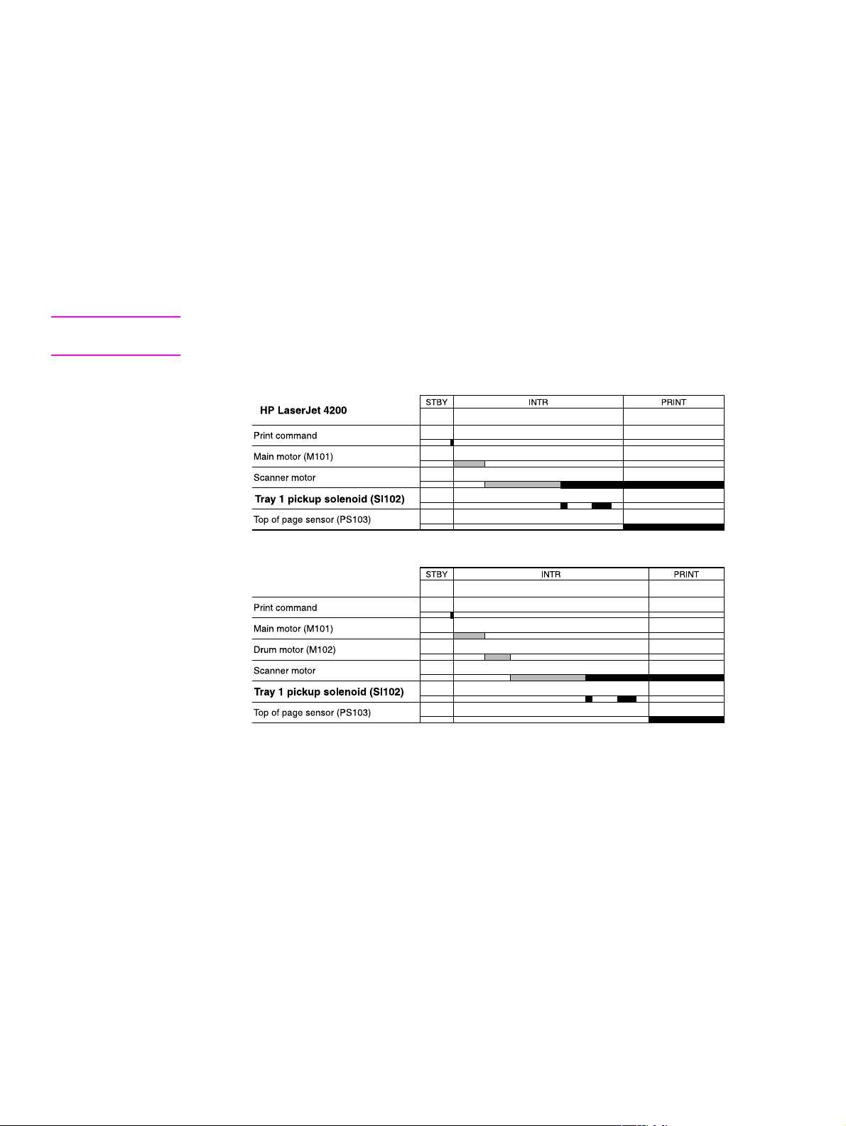
Printer operating sequence
The operating sequence is controlled by a microprocessor on the DC controller PCA. The table
in this section describes the basic operating sequence from when the printer power is turned on
until the final printed page is delivered to an output bin. For information about the timing of the
basic operating sequence, see “HP LaserJet 4200 general timing diagram” on page 357 and
“HP LaserJet 4300 gene ral tim ing diagram” on page 358.
Table 30. Basic printer operating sequence
Period (sequence) Description
Waiting This is the period of time from when the printer power is turned on until the main
motor or drum motor (HPLaserJet 4300 only) begins to rotate. During this time
the transfer roller is cleaned and the microprocessor on the DC controller PCA
checks to determine if a print card ridge is installed in the printer.
Standby This is the period of time from the end of the waiting sequence until the print
command is input from the host computer, or from the end of the last rotation is
input from the sequence (described below) until a print command host computer,
or until the printer po wer is turned off. Th e m essa ge READY appears on th e control-
panel display.
Initial ro tation This is the period of time when th e photos ensit iv e drum is stab iliz ed to prepa re f or
printing.
Print This is the period of time from the initial rotation until control system detects the
page entering the printer (the p age is d etec ted by the top of pa ge sen so r (PS1 03).
Last rotation This is the period of time from the completion of the print job until the main motor
or drum motor (HP LaserJet 4300 only) stops. The final page of the job is
delivered to an output bin and the transfer roller is cleaned. If another print job is
immediately detected (sent by the host computer) the printer returns to the initial
rotation period. If no print jobs are waiting, then the printer returns to the standby
period.
Q2431-90912 Chapter 5 Theory of operation 67
Page 4

Control system overview
The control system consists of the power supply and the DC controller PCA. It controls the
pickup and feed, laser/scanner, and image formation systems. The microprocessor on the DC
controller PCA controls the operating sequence of the printer.
When the printer power is in the standby sequence (see table 30 on page 67), direct current
power (dc voltage) is supplied to the DC controller PCA by the power supply . When the printer is
in the standby sequence (see table 30 on page 67) the microprocessor on the DC controller PCA
sends signals to turn on and off various solenoids, motors, and other printer components needed
to process and print the image data input by the host computer.
Pickup and feed system overview
The pickup and feed system consists of a motor, various rollers, and sensors that detect the
presence of media, transport the media into and through the printer, and deliver the media to an
output bin.
If during the transport process, the media does not reach specific sensors in a specified time, the
microprocessor on the DC controller PCA halts the motor and a jam message appears on the
control-panel display.
Laser/scanner system ov erview
The laser/scanner system forms a latent (or potential) image on a photosensitive drum according
to signals sent from the microprocessor on the DC controller PCA.
The main components of the laser/scanner assembly are the laser driver PCA, the scanner
motor and a six-sided mirror. The DC controller PCA sends image data signals to the laser/
scanner assembly. The laser/scanner PCA converts these data signals into a laser beam of light.
The laser beam of light is reflected by the six-sided mirror onto a photosensitive drum (in the
print cartridge) and a latent image of the image to be printed is created.
Image formation system overview
The image formation system uses toner in the print cartridge to transfer the latent image on the
the photosensitive drum to the media. Heat and pressure (from the fuser) are used to
permanently bond the toner image to the media.
The photosensitive drum (in the print cartridge) receives a uniform negative primary charge that
will be exposed to the laser beam of light.
The photosensitive drum is exposed to the laser beam and an electrostatic latent image is
created on the drum (this image is invisible to your eye) by the laser neutralizing specific areas of
the drum’s surface. When the areas exposed to the laser beam come in contact with toner, the
toner is attracted to them (now the image can be seen on the drum).
The transfer roller applies a positive charge to the back of the media. As the media passes the
photosensitive drum the toner image is attracted to the media and transfers from the drum to the
media.
The media then passes through the fuser where heat and pressure are applied to permanently
bond the toner to the media.
68 Theory of operation Q2431-90912
Page 5
General descriptions
This section describes individual components found in the printer. Information is provided about
the following components.
● DC controller PCA ● 500-sheet feeder
● Power supply assembly ● 1,500-sheet feeder
● Pickup and feed assembly ● envelope feeder
● Laser/scanner assembly ● Duplexer
● Image formation system ● Stacker and stapler/stacker
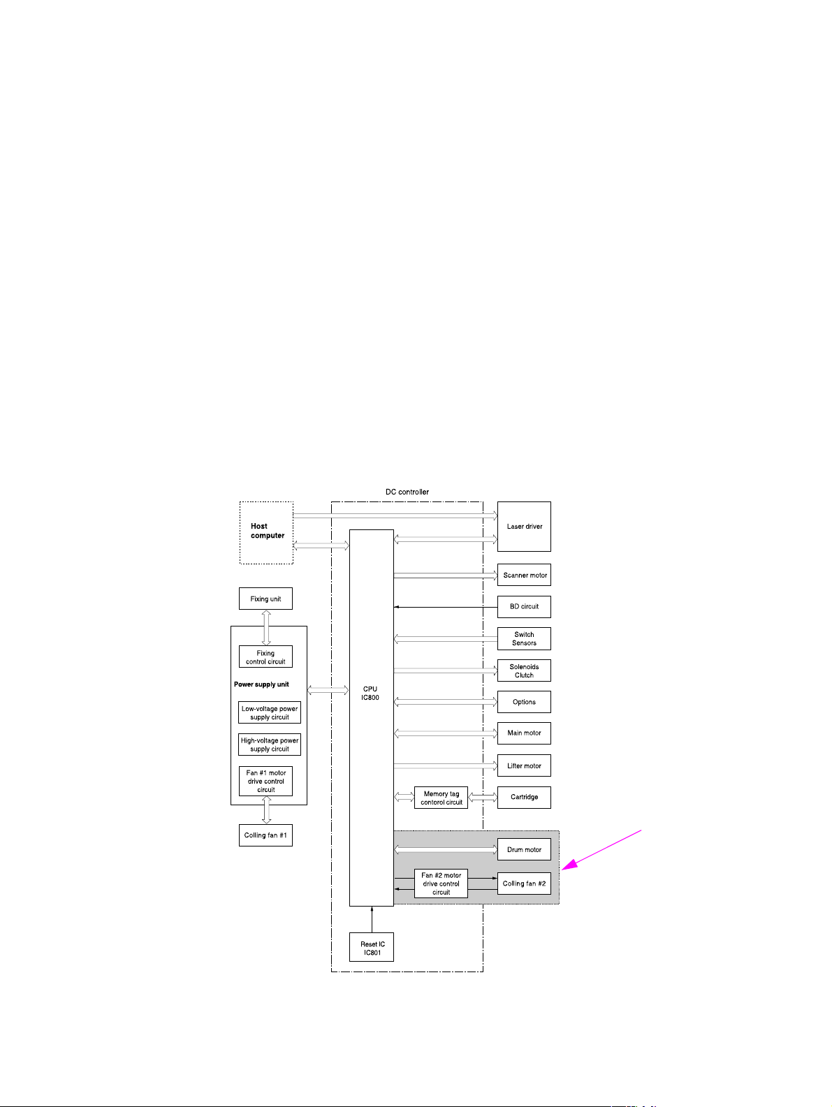
DC controller PCA
The DC controller PCA controls the operation of the printer and its components. The DC
controller PCA starts printer operation when the printer power is turned on and the power supply
sends dc voltage to the DC controller PCA. After the printer enters the standby sequence (see
table 30 on page 67. the DC controller PCA sends out various signals to operate motors,
solenoids and other printer components based on the print command and image data sent by the
host computer. For a list of DC controller PCA connectors, see figure 233 on page 356.
HP LaserJet 4300 only
Figure 6. DC controller PCA block diagram
Q2431-90912 Chapter 5 Theory of operation 69
Page 6

Motor and fan control
The HP LaserJet 4200 printer has three dc brushless motors. The main motor, the lifter driver
motor (inside of the lifter driver assembly), and a fan motor. The main motor is used for image
formation (rotating the photosensitive drum in the print cartridge) and paper pickup and feed.
The lifter motor raises the plate in the tray cassette. The fan motor rotates the fan blades.
The HP LaserJet 4300 printer has five dc brushless motors. The main motor, the print cartridge
motor, the lifter motor, and two fan motors. the main motor is used for paper pickup and feed.
The print cartridge motor rotates the photo sensitive drum (the photosensitive drum used in the
larger HP LaserJet 4300 print cartridge is heavier than the one used in the HP LaserJet 4200
printer). The lifter motor raises the plate in the tray cassette. Two fan motors rotate the left- and
right-side fans.
The DC controller PCA controls the operation of the motors and fans.
Table 31. Printer fans and motors
Motor names Purpose Type Rotation Speed Failure
detection
Motor Main motor (M101)
HP LaserJet 4200
Main motor (M101)
HP LaserJet 4300
Print cartridge
motor (M102)
HP LaserJet 4300
Lifter motor (M103)
HP LaserJet 4200
HP LaserJet 4300
Fan Left-side cooling
fan (FN101)
HP LaserJet 4200
HP LaserJet 4300
Drives the tray cassette
pickup roller, feed /
separation roller, tray 1
pickup roller, pretransfer roller,
photosensitive drum,
developing cylinder,
pressure roller, and
output delivery roller
Drives the tray cassette
pickup roller, feed /
separation roller, tray 1
pickup roller pretransfer rol ler , pres sure
roller, and output
delivery roller.
Drives the transfer
charging roller,
photosensitive drum,
and developing
cylinder.
Moves the tray cassette
lifting plate up and
down.
Cools the inside of the
printer
dc
Counter
motor
clockwise
dc
Counter
motor
clockwise
dc
Counter
motor
clockwise
dc
Counter
motor
clockwise
dc
NA 2-speed
motor
2-speed
(full and half)
2-speed
(full and half)
2-speed
(full and half)
1-speed Yes
(full and half)
Yes
Yes
Yes
Yes
Right-side cooling
fan (FN102)
HP LaserJet 4300
Cools the inside of the
printer.
dc
NA 1-speed Yes
motor
70 Theory of operation Q2431-90912
Page 7
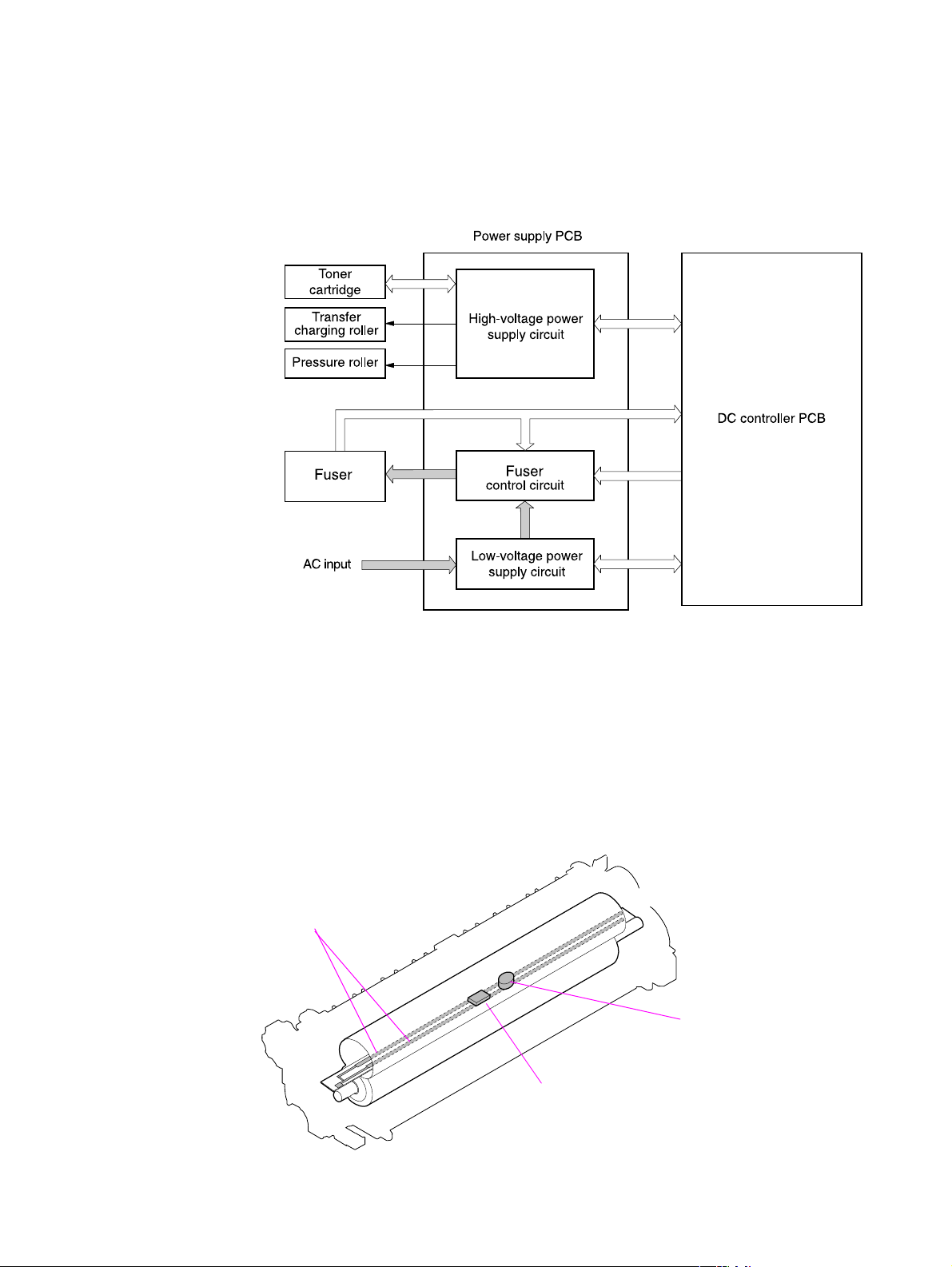
Po wer supply
The power supply consists of the fuser-control circuit, the high-voltage circuit, and the lowvoltage circuit. The fuser-control and high-voltage circuits control the temperature of the fuser
and generate high-voltage according to signals from the DC controller PCA. The low-voltage
circuit generates the dc voltages used by other components in the printer (for example the DC
controller PCA, the motors, and fans).
Figure 7. Power supply block diagram
Fuser-control circuit
The fuser-control ci rcuit c ontro ls the f user ’s components. The two fuser heaters provide the high
temperatures which cause the toner to be permanently bonded to the media. The fuser
thermistor is used to monitor the fuser temperatures. The thermal switch detects abnormally high
fuser temperatures and interrupts the supply of voltage to the fuser if the temperature is
determined to be too high.
Fuser heaters
Fuser thermal switch
Fuser thermistor
Figure 8. Fuser components
Q2431-90912 Chapter 5 Theory of operation 71
Page 8

Fuser over-temperature protection
The fusing heater safety circuit is located on the power supply and constantly monitors the fusing
temperature.
To protect the fuser from excessive temperatures, the printer has the following three protective
functions:
● The CPU monitors the voltage of the thermistor. If the fuser temperature reaches
240° C (464° F) or higher, the CPU turns off the relay (RL101) to interrupt the power
to the fusing heater.
● If the temperature of the fusing heater continues to rise abnormally and the
temperature of the thermistor (TH1) exceeds about 250° C (482° F), the relay 1
(RL101) opens up to cut off the power supply to the fusing heater.
● When the temperature of the heater exceeds about 250° C (482° F), the thermal
switch (TP1) is turned off to cut off the power supply to the fusing heater
.
Figure 9. Fuser over-temperature protection circuit block diagram
72 Theory of operation Q2431-90912
Page 9
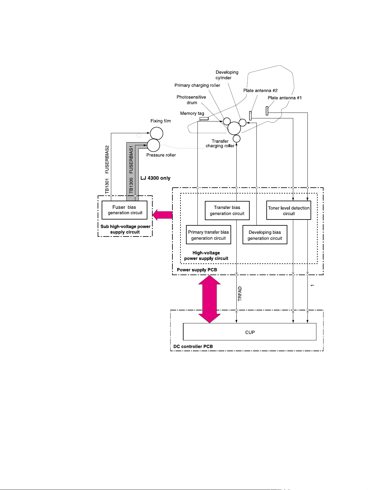
High-voltage circuit
The high-voltage circuit produces the voltage biases that are applied to the primary charging
roller, the developing cylinder, the transfer charging roller, and the pressure roller.
Figure 10. High-voltage circuit block diagram
The primary charging voltage (bias) applies a uniform negative charge to the photosensitive
drum in the print cartridge. There are two types of primary charging biases. The primary charging
dc negative voltage and the primary charging ac bias. Both biases are generated by the highvoltage circuit on the power supply. These biases are superimposed on one another and then
applied to the primary charging roller which will transfer the biases to the drum. The laser/
scanner assembly generates the electrostatic image on the primary charged photosensitive
drum. See “Image formation system overview” on page 68. The electrostatic image cannot be
seen until toner is deposited on the drum.
Q2431-90912 Chapter 5 Theory of operation 73
Page 10
The developing voltage (bias) causes the toner to adhere to the electrostatic image that the
laser/scanner assembly created on the photosensitive drum. There are two types of developing
biases. The developing dc negative bias and the developing ac bias. Both biases are generated
by the high-voltage circuit on the power supply. These biases are superimposed on one another
and then applied to the primary charging roller which will transfer the biases to the drum. The
biased developing cylinder picks up toner particles and deposits them onto the electrostatic
image on the photosensitive drum. The image is now visible on the drum.
The transfer voltage (bias) allows the toner image on the photosensitive drum to transfer to the
media. There are two types of developing biases. The transfer dc positive bias and the dc
negative bias. Both biases are generated by the high-voltage circuit on the power supply.
Transfer dc positive bias is applied to the transfer roller during the toner transfer process.
Transfer dc positive bias is applied to the transfer roller during the transfer roller cleaning
process. The dc positive bias attracts the toner to the media (this transfers the toner image on
the photosensitive drum to the media). The dc negative bias is used to clean residual toner off of
the transfer roller.
The fuser voltage (bias) prevents toner on the media from sticking to the fuser’s pressure roller.
For the HP LaserJet 4200 there is one type of fuser bias. A dc positive bias is generated by the
sub high-voltage circuit on the power supply . The dc positive bias is applied to the pressure roller
in the fuser.
For the HP LaserJet 4300 there are two types of fuser biases. The fuser dc positive bias and a
dc negative bias. Both biases are generated by the sub high-voltage circuit on the power supply .
The dc positive bias is applied to the pressure roller in the fuser. The dc negative bias is applied
to the fixing film in the fuser.
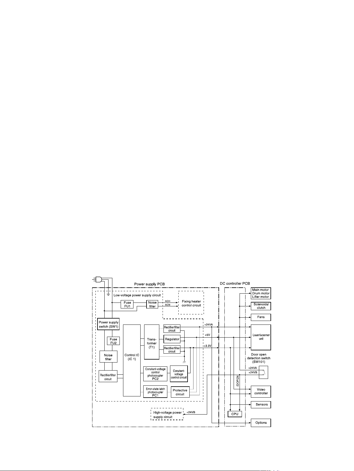
Low-voltage circuit
The low-voltage circuit converts the ac power from the power source (the wall receptacle the
printer’s power cord is plugged into) into the direct current voltage (vdc) used by printer
components (like the motors and fans). The ac voltage is converted into +24 vdc, +5 vdc, and
+3.3 vdc. The +24 vdc voltage is supplied to printer components like the main motor, laser/
scanner assembly motor, solenoids and clutches. The +5 vdc voltage is supplied to the laser/
scanner assembly. The +3.3 vdc is supplied to the sensors and the DC controller PCA.
Figure 11. Low-voltage circuit block diagram
74 Theory of operation Q2431-90912
Page 11

Overcurrent/overvoltage protection
If a short-circuit or other problem on the load side causes an excessive current flow or generates
abnormal voltage, the overcurrent/overvoltage protection systems automatically cut off the
output voltage to protect the power supply circuit.
If the overcurrent or overvoltage protection system are activated and the power supply circuit
does not generate dc voltage, it is necessary to turn the power off, correct the problem, and then
turn the printer on again.
The circuit has two fuses (FU1, FU2), which break and cut off the output voltage if overcurrent
flows through the ac line.
Toner detection
To monitor the toner level, the printer uses two plate antennas and a toner level circuit in the
high-voltage power supply circuit (see figure 10 on page 73). Toner level detection is performed
by the DC controller PCA which monitors the output signal of this circuit. The signal is fed back to
the DC controller PCA from the antennas during the wait and standby operating periods (see
table 30 on page 67). The DC controller PCA detects toner level from 1 percent to 100 percent. If
the toner is detected as being low, a message will appear on the control-panel display (see
“Alphabetical prin ter mess ag es ” on page 258).
Cartridge detection
The presence of the cartridge is detected using information stored in plate antenna 2 and the
print cartridge memory tag (see “High-voltage circuit block diagram” on page 73). The DC
controller PCA detects the presence (or lack of) the print cartridge during the wait operating
sequence ((see table 30 on page 67).
Cartridge memory
This memory is built-in EEPROM in the cartridge, so that the printer is capable of detecting the
cartridge conditions.
Read/write of the cartridge memory is performed by the memory controller board through the
antenna unit. The cartridge information read by the memory controller is updated by the DC
controller PCA and written to the memory. The read/write of the memory is implemented when
the memory controller board receives a command from the DC controller PCA. The DC controller
PCA instructs the memory controller to perform read/write at the following timing.
Reading timing
● When the power is turned on
● When the door is closed
● When the DC controller PCA receives a command from the formatter
Writing timing
● When printing is completed
● When the DC controller PCA receives a command from the formatter
The memory data sent from the memory controller also contains the error status that has
occurred during read/write operation. When error status is sent, the DC controller PCA attempts
to read the operation four times. If the error status is not cleared after the operation, the DC
controller PCA determines one of the following error conditions: sub-CPU failure, memory data
abnormality, or memory access abnormality.
Do not remove the toner cartridge when the top cover interlock is overridden. Cartridge memory
will be disabled.
Q2431-90912 Chapter 5 Theory of operation 75
Page 12
Laser/scanner assembl y
The laser/scanner produces the latent electrostatic image on the photosensitive drum in the print
cartridge.The main components of the laser/scanner assembly are the laser driver PCA, the
scanner motor, various mirrors, and the focusing lenses.
Scanner motor PCA
Scanner motor
Scanner mirror
Focusing lens
BD mirror
Mirror
Figure 12. Laser/scanner assembly
The laser scanner uses two laser diodes to scan two lines simultaneously producing high speed
laser scanning. After receiving the print command from the host computer, the DC controller
PCA activates the scanner motor which rotates the six-sided scanner mirror. The laser driver
PCA emits light from the two laser diodes according to signals from the DC controller PCA. The
two laser beams strike the six-sided scanning mirror and are directed through the focusing
lenses and down onto the photosensitive drum. The modulated laser beams generate the latent
electrostatic image on the photosensitive drum according to the image data signals received
from the DC controller PCA.
BD PCA
Photosensitive drum
(inside the print cartridge)
Laser beams
76 Theory of operation Q2431-90912
Page 13
Laser/scanner control
The laser/scanner control circuit on the laser driver PCA turns the laser diodes on an off
according to image data signals received from the DC controller PCA. The DC controller PCA
sends image data signals VD01/VD01,VD02, and /VD02 and the laser control signals CNT0,
CNT1, and CNT2 to the logic circuit on the laser driver PCA. The laser control signals control
laser emission, automatic power control (APC), horizontal synchronization control, and image
mask control.
Figure 13. Laser control circuit block diagram
Laser emission control is simply turning the laser diodes on and off. Automatic power control is
used to limit the amount of light that is emitted from the laser diodes. Horizontal synchronization
control is used to determine the starting position for the images horizontal direction. Image mask
control is used to avoid laser beam emission on the non-imaging areas of the drum (about 5mm
down the vertical edges and 8mm at the top and bottom)
Q2431-90912 Chapter 5 Theory of operation 77
Page 14
Paper pickup system
The paper pickup and feed system consists of various kinds of pickup and feed rollers that are
driven by the printer’s motor(s). The printer uses tray 1 (the manual feeding tray) and a cassette
in tray 2 as media sources. The printed media is delivered to either the rear output bin (straight
through printing) or the top output bin (the default destination). Two additional 500-sheet feeders
and one 1,500-sheet feeder can be added to the printer. These accessories are discussed
further along in this chapter.
Media is detected in tray 1 by the tray 1 paper sensor (on the tray 1 pickup assembly; PS105).
The media is detected in tray 2 by the tray 2 paper sensor (PS101). The paper size sensor
(PS106) and the paper size switch (SW102) detect the media that is loaded in the tray 2
cassette.
All of the rollers in the printer are driven by two motors, a clutch, and a solenoid which are
controlled by the DC controller PCA (for the HP LaserJet 4300 has three motors). See “Motor
and fan control” on page 70.
The pre-feed, top of page, and fuser assembly delivery sensor (PS102, PS103, PS108) detect
arrival and passing of media along the paper path. If the paper does not reach or pass these
sensors within a specific amount of time the microprocessor on the DC controller PCA halts the
printer functions and a jam error message will appear on the control-panel display. See
“Alphabetical printer messages” on page 258 and “Numerical prin ter mess ag es ” on page 274.
For information about the location of printer switches, sensors, and motors see “Printer switches
and sensors” on page 336 and “Printer motors and fans” on page 337.
Figure 14. Printer paper pickup and feed block diagram
78 Theory of operation Q2431-90912
Page 15
The paper pickup and feed system is divided into two blocks. The paper pickup/feed block, and
the fuser/delivery block.
Fuser/delivery block
Figure 15. Paper pickup/feed and fuser/delivery block diagram
Paper pickup and feed block
Paper pickup/feed block
The printer functions that take place in the pickup/feed block are cassette media size and
presence detection, media entering the paper path from tray 1 or tray 2, Lifting of the tray 2
paper plate, multiple feed prevention, and page skew correction. For information about the
locations of switches, sensors, and motors in the pickup/feed block, see “Printer switches and
sensors” on page 336 and “Printer motors and fans” on page 337.
When the print command is received from the host computer by the DC controller PCA it turns
the main motor (M101) power on. This motor will drive the tray 2 pickup, feed, and separation
rollers to rotate. For the HP LaserJet 4300, the print cartridge motor power also is turned on. The
laser/scanner motor power is turned on.
The DC controller PCA then activates the feed clutch (CL101) to rotate the feed roller. The tra y 2
pickup solenoid is activated (SL101) and the pickup arm descends. The pickup roller touches the
media and a sheet is fed into the printer. The separation roller prevents multi-sheets of media
from being fed all at one time.
As the pre-feed sensor (PS102) detects the media, the DC controller PCA turns off the clutch
which stops the media. When the DC controller PCA detects that the laser/scanner is ready it
activates the feed clutch again. The feed roller moves the media further into the printer. Page
skew is corrected by the registration shutter and the media is transported to the fuser/delivery
block (feed belt, fuser, and delivery output bin).
For information about the timing of these operations, see “HP LaserJet 4200 general timin g
diagram” on page 357 and “HP LaserJet 4300 general timing diagram” on page 358.
Q2431-90912 Chapter 5 Theory of operation 79
Page 16
Printing from tray 1
The presence of paper in tray 1 is detected by the tray 1 paper sensor (PS105).
When the DC controller PCA receives the print command, the printer starts the initial rotation
phase. (This consists of main motor warm-up, scanner motor warm-up, high-voltage control
sequence and fuser warm-up.) When the initial rotation phase ends, the tray 1 pickup solenoid
(SL102) is activated.
The cam rotates, the paper tray lifter rises, and the media comes in contact with the tray 1 pickup
roller. At the same time, the tray 1 pickup roller rotates twice and a sheet of media in tray 1 is
picked up. The separation pad prevents unnecessary sheets from feeding with the first sheet.
The sheet then reaches the registration assembly, where its skew is corrected. Then it goes
through transfer, separation, and fusing stages; passes through the delivery unit; and is
delivered to the output bin.
Note If paper is removed from tray 1 just before it is picked, the tray 1 pickup roller might continue to
rotate up to six times and a jam will be detected.
Figure 16. Tray 1 timing diagrams
80 Theory of operation Q2431-90912
Page 17
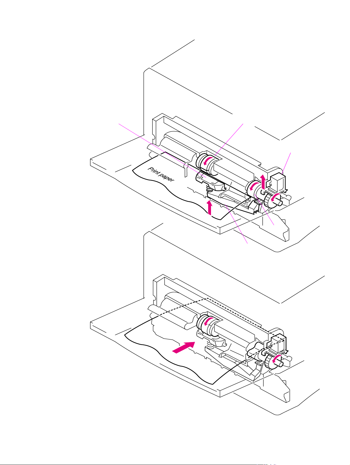
Separation pad
Tra y 1 pic kup roller
Tra y 1 pic kup solenoid
Cam
Lifter
Figure 17. Tray 1 pickup
Q2431-90912 Chapter 5 Theory of operation 81
Page 18
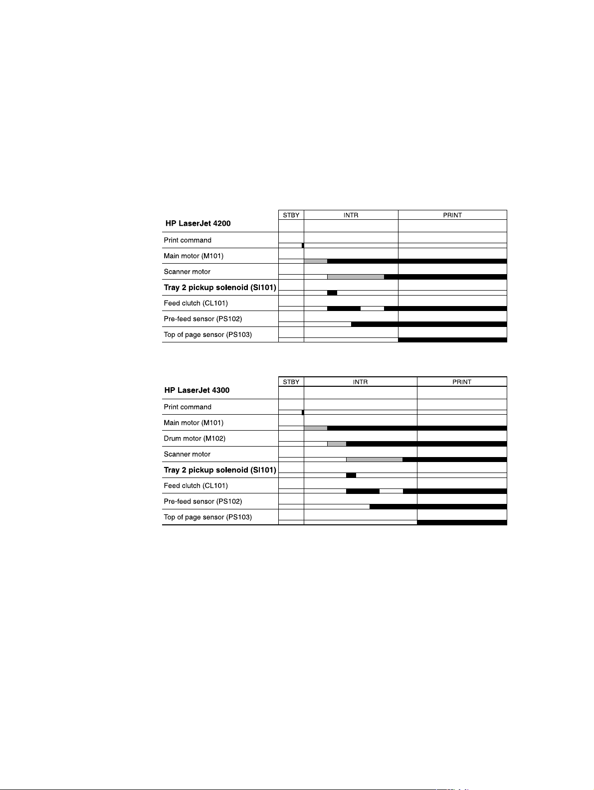
Printing from tray 2
When the DC controller PCA receives print command, the main motor (M101) and scanner
motor start rotation. When the main motor reaches its prescribed speed, the feed roller clutch
(CL101) and tray 2 pickup solenoid (SL101) are activated. (The tray 2 pickup roller, tray 2 feed
roller, tray 2 separation roller, and paper feed rollers are driven by the main motor rotation.)
The tray 2 pickup roller, activated by the pickup solenoid, rotates once and picks up the media in
the tray. The unnecessary sheets are removed by the separation roller and the media is fed to
the pre-feed sensor (PS102).
The sheet then reaches the registration assembly, where its skew is corrected. Then it goes
through transfer, separation, and fusing stages; passes through the delivery unit; and is
delivered to the output bin.
Figure 18. Tray 2 timing diagrams
82 Theory of operation Q2431-90912
Page 19

Tray 2, 500-, 1,500-sheet feeder media size detection
Media size in the cassette are detected by three switches. The switches are active after the
cassette is placed in the tray 2 feeder. (this also applies to the optional 500- and 1,500-sheet
feeder). The DC controller PCA microprocessor detects the size and presence of the media by
the combinations of the switches.
Table 32. Tray 2 and 500-sheet feeder media size switch settings
Paper size Media size switch setting
Upper Center Lower
No cassette installed
A4
LTR
B5
A5
EXE
LGL
UNV
Off Off Off
Off Off On
Off On Off
Off On On
On Off Off
On Off On
On On Off
On On On
Table 33. 1,500-sheet feeder media size switch settings
Paper size Media size switch setting
Upper Center Lower
No cassette installed
A4
LTR
LGL
Off Off Off
On Off On
Off On On
On On Off
The tray 2 cassette can detect the media size using the switches describe above, however the
user can define the media size for the tray using the control-panel (see “Paper Handling menu”
on page 42). In this case the printer may not correctly detect the media size if the user’s defined
size does not match the tray settings.
To prevent a false size detection, the printer measures the time it takes for the media to pass
from its leading edge to its trailing edge and determines the media size that was fed from the
tray. When the measured size differs from the user’s defined size or from the media size
switches, a message will appear on the control-panel display (see “Alphabetical printer
messages” on page 258).
Q2431-90912 Chapter 5 Theory of operation 83
Page 20
Lifter-driver operation
The lifter driver keeps the media stack surface at a specific level in order to have a stabilized
pickup operation regardless of the size of the media in the tray 2 cassette. The DC controller
PCA operates the lifter driver motor (M103) for 50 seconds. The motor stops when the paper
stack position sensor (PS107) detects the media. If the paper stack position sensor does not
detect any media within 8 seconds after the lifting operation has begun, the DC controller PCA
determines there has been a lifter driver motor failure and a message appears on the controlpanel display (see “Alphabetical printer messages” on page 258 or “Numeric al printer
messages” on page 274). The DC controller PCA stops the lifting operation if the paper stack
position sensor detects the absence of the tray 2 cassette.
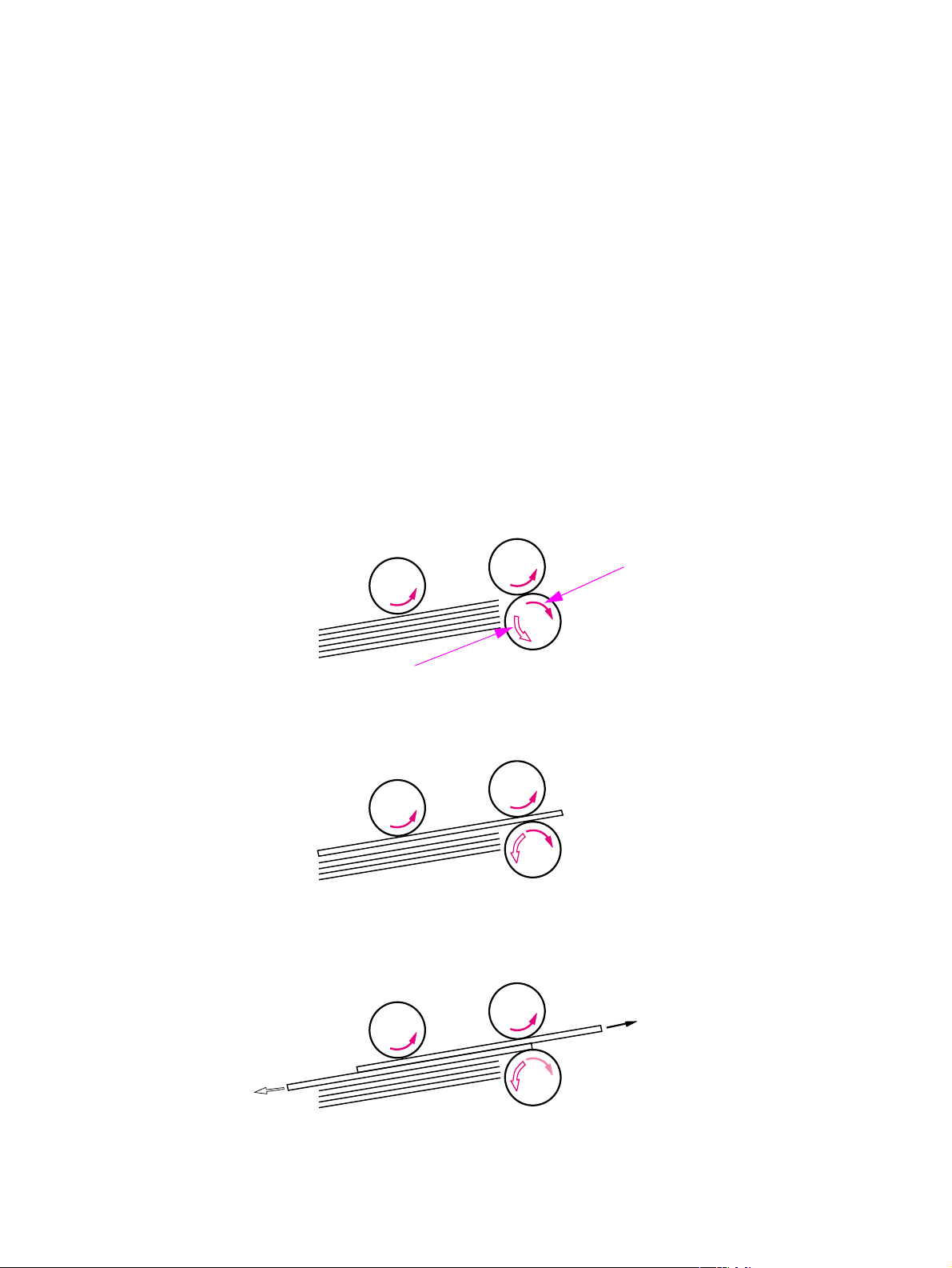
Multiple feed prevention
The printer uses the separation roller in tray 2 to prevent multiple-feeding. Normally, the
separation roller rotates in the same direction as the feed roller. The separation roller is equipped
with a torque limiter, but because the force of the feed roller exceeds that of the torque limiter, the
separation roller is actually driven by the feed roller.
If multiple sheets of media are picked up, however, the low friction force between the sheets
weakens the rotational force from the feed roller to the separation roller. Consequently, the
torque limiter takes control of the separation roller, and rotates the separation roller in the reverse
direction, which removes the extra sheets.
Feed roller
Pickup roller
Media
Normal
Driving force transmitted from the feed roller
Separation roller
Driving force transmitted from the motor through the torque limiter
Multiple feed
Figure 19. Multiple feed prevention
84 Theory of operation Q2431-90912
Page 21

Media skew prevention
The printer uses a registration shutter on the registration assembly to prevent media from
entering the printer skewed (without decreasing the throughput speed). When media is fed to the
registration assembly its leading edge contacts the registration shutter, but does not yet open the
shutter. The feed roller continues to rotate and the media begins to sag. The sagging papers
leading edge comes in full contact with the shutter (skew is corrected at this point) and raises the
registration shutter. With the shutter out of the way, the media can continue into the printer paper
path.
Registration assem bly shutter
Leading edge contacts
the shutter
Media sags and the
entire leading edge
contacts the shutter
Skew is corrected and
the shutter rais es up . The
media can contin ue along
the paper path.
Figure 20. Correcting skewed media pages
Q2431-90912 Chapter 5 Theory of operation 85
Page 22

Fixing/delivery block
The paper pickup and feed system is divided into two blocks. The paper pickup tray to the fuser
block, and the fuser to output bin block.
Fuser/delivery block
Figure 21. Paper pickup/feed and fuser/delivery block diagram
The fuser/delivery block consists of the various rollers, sensors, the fuser, and the output
delivery assembly. The rollers transport the media through the fuser/delivery block paper path.
The fuser applies heat and pressure to the media to permanently bond the toner image (which
was transferred to the media from the photosensitive drum in the print cartridge) to the media.
The output delivery assembly sends the printed media either to the rear output bin (if the rear
output door is open) or to the top output bin (the default output delivery bin). Sensors along the
paper path detect the movement of the media, jams if they occur, and when the top output bin is
full.
Paper pickup/feed block
86 Theory of operation Q2431-90912
Page 23

Printer jam detection
The printer uses the following sensors to detect the presence of media and to verify if the media
is being fed properly or has jammed. For information about the location of these sensors, see
“Printer switches and sensors” on page 336.
● Pre-fed sensor (PS102)
● Top of page sensor (PS103)
● Fuser delivery sensor (PS108)
The microprocessor on the DC controller PCA checks for media jamming by timing the passing
of the media as it moves past these sensors. If the media does not pass the sensor in a specific
period of time, the transport process is stopped (motors are turned off and the rollers no longer
rotate) and a jam message appears on the control-panel display.
Printer pickup delay jam from tray 1
If the top of page sensor (PS103) does not detect the leading edge of the media within a specific
time after the media is picked up the microprocessor on the DC controller PCA determines there
is a pickup jam.
Note The printer attempts to re-pickup the media several times before determining there is a pickup
jam. The number of re-pickup tries depends on the pickup source (for example, the re-pickup is
tried 4 times if tray 1 is the pickup source).
The transport process is stopped and a 13.XX.YY JAM message appears on the control-panel
display. For more information about jam messages, see “Alphabetical printer messages” on
page 258 and “Numeri c al printer messages” on page 274.
Printer pickup delay jam from tray 2
If the pre-feed sensor (PS102) does not detect the leading edge of the media within a specific
time after the media is picked up the microprocessor on the DC controller PCA determines there
is a pickup jam.
Note The printer attempts to re-pickup the media several times before determining there is a pickup
jam. The number of re-pickup tries depends on the pickup source (for example, the re-pickup is
tried 4 times if tray 1 is the pickup source).
The transport process is stopped and a 13.XX.YY JAM message appears on the control-panel
display. For more information about jam messages, see “Alphabetical printer messages” on
page 258 and “Numeri c al printer messages” on page 274.
Printer pickup stationary jam
If the top of page sensor (PS103) does not detect the trailing edge of the media within a specific
time after the media is picked up the microprocessor on the DC controller PCA determines there
is a pickup jam.
The transport process is stopped and a 13.XX.YY JAM message appears on the control-panel
display. For more information about jam messages, see “Alphabetical printer messages” on
page 258 and “Numeri c al printer messages” on page 274.
Q2431-90912 Chapter 5 Theory of operation 87
Page 24

Printer delivery wrap jam when feeding regular media
Regular size media is defined as A4, letter, legal, B5, executive or A5.
If the fuser delivery sensor (PS108) does not detect the trailing edge of the media after a
specified fusing time the microprocessor on the DC controller PCA determines there is a fuser
wrap jam.
The transport process is stopped and a 13.XX.YY JAM message appears on the control-panel
display. For more information about jam messages, see “Alphabetical printer messages” on
page 258 and “Numerical printer messages” on page 274.
Printer delivery wrap jam when feeding non-regular media
Non-regular media is defined as media that is less than 200mm (7.9 inches) in length.
If the fuser delivery sensor (PS108) does not detect the trailing edge of the media within a
specified time after a fuser wrapping jam is detected, the microprocessor on the DC controller
PCA determines there is a fuser wrap jam.
Or If the fuser delivery sensor (PS108) does not detect the trailing edge of the media within a
specified time after it has detected the leading edge of the media the microprocessor on the DC
controller PCA determines there is a fuser wrap jam.
The transport process is stopped and a 13.XX.YY JAM message appears on the control-panel
display. For more information about jam messages, see “Alphabetical printer messages” on
page 258 and “Numerical printer messages” on page 274.
Printer delivery delay jam
If the fuser delivery sensor (PS108) does not detect the trailing edge of the media within a
specific time after detecting the leading edge of the media, the microprocessor on the DC
controller PCA determines there is a fuser stationary jam.
The transport process is stopped and a 13.XX.YY JAM message appears on the control-panel
display. For more information about jam messages, see “Alphabetical printer messages” on
page 258 and “Numerical printer messages” on page 274.
If the fuser delivery sensor (PS108) detects the trailing edge (paper out) of the media within a
specified time, after it has detected the leading edge of the media the microprocessor on the DC
controller PCA determines there is a delivery jam.
However, if the paper length detected by the top of page sensor (PS103) does not match the
media size that the printer expects from the pickup source, this jam is ignored. The top of page
sensor (PS103) determines the length of the page by measuring the tim it takes between the
passing of the leading and trailing edges of the page.
The transport process is stopped and a 13.XX.YY JAM message appears on the control-panel
display. For more information about jam messages, see “Alphabetical printer messages” on
page 258 and “Numerical printer messages” on page 274.
Note This jam cannot be detected for pages that are less than 200mm (7.9 inches) in length.
88 Theory of operation Q2431-90912
Page 25

Printer door open jam
If the top door is opened (this will activate the top door open switch; SW101) during a print
operation, the microprocessor on the DC controller PCA determines there is door open jam.
The transport process is stopped and a 13.XX.YY JAM message appears on the control-panel
display. For more information about jam messages, see “Alphabetical printer messages” on
page 258 and “Numeri c al printer messages” on page 274.
Printer residual media jam
If either the top of the page sensor (PS103) or the fuser delivery sensor (PS108) does not detect
the leading edge of the media at the start of initial rotation (see table 30 on page 67) the
microprocessor on the DC controller PCA determines there is residual media jam.
Q2431-90912 Chapter 5 Theory of operation 89
Page 26

Printing from the 500-sheet feeder
Note The HP LaserJet 4200/4300 series printers support up to two optional 500-sheet feeders.
The paper-feeder driver controls the operation sequences of the 500-sheet feeder. An 8-bit
microprocessor in the paper-feeder driver controls the 500-sheet feeder sequences and the
communication with the DC controller PCA.
The paper-feeder driver drives the solenoid in response to the pickup command. The paperfeeder driver also returns the status of the paper feeder to the DC controller PCA.
The printer delivers a charge of +24 vdc to the paper feeder, which then generates +3.3 v for the
integrated circuits.
Figure 22. 500-sheet feeder I/O block diagram
500-sheet feeder pic k up and f ee ding
Three switches on the paper-feeder driver detect the media size and the presence of the 500sheet tray. The relationship between the switch combinations and the paper sizes is the same as
for the printer. See table 32 on page 83.
The main motor (M101) of the printer drives the paper feeder. When the DC controller PCA
sends a print command to the paper feeder, the main motor of the printer begins to rotate. When
the scanner motor reaches its prescribed speed, the paper-feeder driver receives the pickup
command from the DC controller PCA and activates the paper-feeder pickup solenoid. (The
main motor drives the pickup roller, feed roller, and separation roller.)
90 Theory of operation Q2431-90912
Page 27

The pickup roller, activated by the solenoid, rotates once, picking up the media inside the 500sheet tray. The separation roller removes any unnecessary sheets and the media travels to the
pre-feed sensor (PS102).
The sheet then reaches the registration assembly, where its skew is corrected. Then it goes
through transfer, separation, and fusing stages; passes through the delivery unit; and is
delivered to the output bin.
Note The 500-sheet feeder detects pickup and feed jams in the same way as the printer. See “Printer
jam detection” on page 87.
Figure 23. 500-sheet feeder pickup and feed diagram
Q2431-90912 Chapter 5 Theory of operation 91
Page 28

Printing from the 1,500-sheet fe eder
The paper-feeder driver controls the operation sequences of the 1,500-sheet feeder. An 8-bit
microprocessor in the paper-feeder driver controls the 1,500-sheet feeder sequences and the
communication with the DC controller PCA.
The paper-feeder driver drives the solenoid in response to the pickup command. The paperfeeder driver also returns the status of the paper feeder to the DC controller PCA.
The printer delivers a charge of +24 vdc to the 1,500-sheet feeder, which then generates +3.3 v
for the integrated circuits.
Figure 24. 1,500-sheet feeder I/O block diagram
1,500-sheet feeder pickup and feeding
Three switches on the paper-feeder driver detect the media size and the presence of the 1,500sheet tray. The relationship between the switch combinations and the paper sizes is the same as
for the printer. See table 32 on page 83
The main motor (M101) of the printer drives the paper feeder. When the DC controller PCA
sends a print command the main motor of the printer begins to rotate. When the scanner motor
reaches its prescribed speed, the paper-feeder driver receives the pickup command from the DC
controller PCA and activates the paper pickup solenoid. (The main motor drives the pickup roller,
feed roller, and separation roller.)
The pickup roller, activated by the solenoid, rotates once, picking up the media inside the
1,500-sheet tray. The separation roller removes any unnecessary sheets and the media travels
to the pre-feed sensor (PS102).
The sheet then reaches the registration assembly, where its skew is corrected. Then it goes
through transfer, separation, and fusing stages; passes through the delivery unit; and is
delivered to the output bin.
Note The 1,500-sheet feeder detects pickup and feed jams in the same way as the printer. See“Printer
jam detection” on page 87.
92 Theory of operation Q2431-90912
Page 29

Figure 25. 1,500-sheet feeder pickup and feed diagram
Q2431-90912 Chapter 5 Theory of operation 93
Page 30

1,500-sheet feeder lifting mechanism
The lifting mechanism maintains the media stack surface at a specific position inside the 1,500sheet feeder. This allows the feeder to perform a stabilized pickup operation regardless of the
size of the media loaded in the feeder. The lift plate inside of the feeder is lifted by two wire
cables. A motor (M1) winds these wires up using pulleys in the feeder. When the front door of the
feeder is opened, the pulley gears and the motor gear are disengaged and the lift plate lowers
under its own weight. The lifting mechanism is active (the plate is in the raised position) when it
is signaled by the DC controller PCA, the front door is closed, or during the print operation. The
1,500-sheet feeder control PCA driver stops the motor (M1) when the 1,500-sheet feeder paper
stack position sensor (SR2) detects media.
If the 1,500-sheet feeder paper stack position sensor (SR2) does not detect media within about
30 seconds after the start of the lift operation, the paper-deck driver PCA detects a lifter motor
failure and sends a signal to the DC controller PCA. An error message appears on the controlpanel display.
Figure 26. 1,500-sheet feeder lifting mechani sm
94 Theory of operation Q2431-90912
Page 31

Envelope feeder
The envelope-feeder driver controls the operation sequences of the envelope feeder. An 8-bit
microprocessor in the envelope feeder driver controls the envelope-feeder sequence and the
communication with the DC controller PCA.
The DC controller PCA sends the pickup command to the envelope-feeder driver with the
necessary timing. The envelope-feeder driver activates the solenoid in response to the
command.
The printer delivers a charge of +24 vdc to the envelope feeder, which then generates +5 v for
the integrated circuits.
Figure 27. Envelope feeder I/O block diagram
Q2431-90912 Chapter 5 Theory of operation 95
Page 32

Envelope feeder pickup and feeding
In the envelope feeder, the env elope sensor (PS901) detects the presence of envelopes and the
envelope-size sensor (PS903) detects the width of the envelope. The envelope pickup motor
(M901) drives all of the rollers in the envelope feeder.
When the DC controller PCA sends a print command the main motor (M101) in the printer begins
to rotate. After the main motor initial rotation phase is completed, the scanner motor begins to
rotate. As the scanner motor rotates, the envelope pick-up motor (M901) begins to rotate to drive
the pickup roller, feed roller, and separation roller, and an envelope is picked up.
The separation roller removes any unnecessary envelopes and the envelope travels to the
printer. The registration assembly corrects any skew. The envelope travels through the printer
paper path and is delivered to the output bin.
Figure 28. Envelope feeder pickup and feed diagram
96 Theory of operation Q2431-90912
Page 33

Envelope feeder jam detection
The envelope feeder uses the envelope multiple feed sensor (PS902) along with sensors in the
printer to detect the presence of media and to determine whether the media is feeding properly
or is jamming.
If a jam occurs in the envelope feeder, the error message 13.XX.YY appears on the control-panel
display. For more information see “Numerical printer messages” on page 274.
Envelope feeder pickup delay jam
If the pickup sensor (PS103) does not detect the leading edge of the envelope within a specific
time after the envelope is picked up, it attempts to pick up the media several times before
determining that a pickup jam has occurred.
If the pre-fed sensor inside of the printer (PS102) does not detect the leading edge of the
envelope within a specific amount of time after the re-pick operation stops, the microprocessor
on the DC controller PCA determines that a jam has occurred.
The transport process stops and a 13.XX.YY message appears on the control-panel display. For
more information about jam messages, see “Numerical printer messages” on page 274.
Envelope feeder pickup stationary jam
If the envelope multiple feed sensor (PS902) detects multiple fed envelopes after the pickup
operation begins The transport process stops and a 13.XX.YY message appears on the controlpanel display. For more information about jam messages, see “Numerica l pr in ter mess ag es ” on
page 274.
Q2431-90912 Chapter 5 Theory of operation 97
Page 34

Duplexer
The duplexer driver controls the operation of the duplexer. An 8-bit microprocessor in the
duplexer driver controls the duplexer sequence and the communication with the DC controller
PCA.
The duplexer driver drives the solenoid, motors, and fan according to commands that the DC
controller PCA sends to the duplexer. The duplexer also communicates its status to the DC
controller PCA.
The printer delivers a charge of +24 vdc to the duplexer, which then generates +5 v for the
integrated circuits.
Figure 29. Duplexer I/O block diagram
98 Theory of operation Q2431-90912
Page 35

Reversing and duplexer pickup
The duplexer has two stepping motors: the reversing motor (M701) and the duplex feed motor
(M702). The duplexer driver controls forward and reverse rotations of the motor.
The face-up output tray diverter, which is controlled by the duplexer solenoid, feeds print media
to the duplexer.
Note The duplexer cannot be used if the face-up tray is open,.
When the trailing edge of the media passes the reverse sensor (PS703), the reversing motor
changes direction. The oblique roller and feed roller then move the media so that its edge makes
contact with the left panel to correct skew.
Figure 30. Duplexer pickup and reversing diagram
Q2431-90912 Chapter 5 Theory of operation 99
Page 36

Duplexer jam detection
The following paper sensors detect whether or not the print media is present and is feeding
normally.
● Tray 2 paper sensor (PS101)
● Pre-feed sensor (PS102)
● Top-of-page sensor (PS103)
● Face-down tray paper-full sensor (PS104)
● Tray 1 (multipurpose tray) paper sensor (PS105)
● Paper width sensor (PS106)
● Fuser delivery sensor 1 (PS108)
The microprocessor on the DC controller PCA detects a jam by using the sensor to check for
media presence at a specific timing that is stored in the memory.
If the DC controller PCA detects that a jam has occurred, it stops print operation and an error
message appears on the control-panel display. See “Alphabetical printer messages” on
page 258 and “Numerical printer messages” on page 274.
100 Theory of operation Q2431-90912
Page 37

Stacker and stapler/stacker
The stacker delivers media from the printer to the stacker delivery bin. The stapler/stacker
staples the media together, and then delivers it to the stapler/stacker delivery bin. The DC
controller PCA controls the stacker and stapler/stacker. When the stacker or stapler/stacker
feeds, the DC controller PCA sends page information (for example, the paper size or whether the
page is the first or last page of the job) to the stacker or stapler/stacker.
Stacker
Figure 31. Stacker and stapler/stacker paper path
Stapler/stacker
Q2431-90912 Chapter 5 Theory of operation 101
Page 38

The following diagram illustrates the power-on sequence for the stacker and stapler stacker.
Figure 32. Power-on sequence for the stacker and stapler/stacker
102 Theory of operation Q2431-90912
Page 39

Stacker
The DC controller PCA controls the stacker and sends signals to the stacker driver PCA. The
stacker driver PCA then controls the operation of the stacker components like the stacker motor,
solenoid, and sensors. When the printer power is turned on, dc power from the printer’s lowvoltage supply circuit is supplied to the stacker. The stacker performs the power-on sequence
(see figure 32 on page 102) and enters the standby mode. When it receives a signal from the DC
controller PCA, the stacker driver PCA activates the motors and solenoids as needed to perform
the stack operation.
Figure 33. Stacker driver PCA block diagram
Q2431-90912 Chapter 5 Theory of operation 103
Page 40

Stacker feed and delivery
The stacker feed and delivery system consists of several feed rollers and guides that the stacker
motor and solenoids drive. Sensors along the stacker paper path detect the arrival and passing
of media and confirm the position of the jogger guide. The jogger guide helps to align the pages
before placing them in the delivery bin.
Table 34. Stacker components
Component Purpose
Motor Feed motor (M103) Rotates the feed and delivery roller
Solenoid Deflector solenoid (SL1101) Operates the delivery deflector
Sensor Paper inlet sensor (PS1101) Used for jam detection
Paper delivery sensor (PS1102) Used for jam detection
Delivery paper full sensor (PS1106) Detects that the delivery bin is full
Switch Door open switch (SW1101) Detects an open door
After the leading edge of the media reaches the fixing delivery sensor (PS108) in the printer, the
DC controller PCA sends a signal to the stacker driver PCA. The stacker driver PCA activates
the deflector solenoid (SL101) for a specific amount of time to move the delivery deflector into
place in the printer which routes the media to the stacker rather than to the printer’s top output
bin. The stacker driver PCA also activates the stacker motor (at the same speed as the printer’s
main motor) to rotate the feed and delivery rollers).
The feed roller moves the media into the stacker. If the DC controller PCA sends a
following-page signal (which means there is another page in the job), the stacker driver PCA
activates the deflector solenoid (SL101) again. The delivery roller moves the media into the
delivery bin.
Delivery bin
Delivery
Feed roller
Deflector
Figure 34. Stacker feed delivery diagram
104 Theory of operation Q2431-90912
Page 41

Stacker jam detection
The stacker uses the following sensors to detect the presence of media and to verify whether the
media is feeding correctly or is jamming. For information about the location of these sensors, see
“Stacker and stapler/stacker switches and sensors” on page 345.
● Paper inlet sensor (PS1101)
● Paper delivery sensor (PS102)
Stacker feed jam
If the paper inlet sensor (PS1101) does not detect the leading edge of the media within a specific
time after the stacker driver has received the paper delivery signal, the DC controller PCA
determines that a stacker feed delay jam has occurred.
The transport process stops and a 13.XX.YY JAM message appears on the control-panel
display. For more information about jam messages, see “Alphabetical printer messages” on
page 258 and “Numeri c al printer messages” on page 274.
Stacker feed stationary jam
If the paper inlet sensor (PS1101) does not detect the trailing edge of the media within a specific
time after the paper inlet sensor (PS1101) detected the leading edge of the media, the DC
controller PCA determines that a stacker feed delay jam has occurred.
The transport process stops and a 13.XX.YY JAM message appears on the control-panel
display. For more information about jam messages, see “Alphabetical printer messages” on
page 258 and “Numeri c al printer messages” on page 274.
Stacker residual media jam
If the paper inlet sensor (PS1101) or the paper delivery sensor (PS1102) detects media during
the initial drive period, the DC controller PCA determines that a stacker feed delay jam has
occurred.
The transport process stops and a 13.XX.YY JAM message appears on the control-panel
display. For more information about jam messages, see “Alphabetical printer messages” on
page 258 and “Numeri c al printer messages” on page 274.
Note This jam only occurs if the paper delivery sensor (PS1102) detects media at the start of the initial
drive.
Q2431-90912 Chapter 5 Theory of operation 105
Page 42

Stapler/stacker
The DC controller PCA controls the stapler stacker by sending signals to the stapler/stacker
driver PCA. The stapler/stacker PCA controls the stapler/stacker motor, solenoids, sensors, and
the stapler unit. When the printer power is turned on dc power from the printer’s low-voltage
supply circuit is supplied to the stapler/stacker. The stapler/stacker performs the power on
sequence (see figure 32 on page 102) and enters the standby mode. When the DC controller
PCA sends a signal, the stapler/stacker driver PCA activates the motors and solenoids as
needed to perform the staple and stack operation.
Figure 35. Stapler/stacker driver PCA block diagram
106 Theory of operation Q2431-90912
Page 43

Stapler/stacker feed and delivery
The stapler/stacker feed and delivery system consists of several feed rollers and guides that are
driven by the stapler/stacker motors and solenoids. Sensors along the stapler/stacker paper path
detect the arrival and passage of media and confirm the position of the jogger guide. The jogger
guide helps to align the pages before stapling and dropping them into the delivery bin.
The stapler/stacker has two modes. The staple mode staples media together and drops them
into the delivery bin. The stack mode drops the media directly into the delivery bin without
stapling them together.
Table 35. Stapler/stacker components
Component Purpose
Motor Paddle motor (M1101) ● Rotates the paddle (clockwise)
● Disengages the delivery roller (counterclockwise)
Jogger motor (M1102) Shifts the jogger guide.
● Widens the jogger guide (clockwise)
● Narrows the jogger guide (counterclockwise)
Feed motor (M103) Rotates the feed and delivery roller
Stapler motor (M1104) Rotates the staple cam
Solenoid Deflector solenoid (SL1101) Operates the delivery deflector
Clamp solenoid (SL1102) Operates the stapler clamp
Sensor Paper inlet sensor (PS1101) Detects jams
Paper delivery sensor (PS1102) Detects jams
Paddle home sensor (PS1103) Detects if the paddle is in the home position
Delivery roller disengaging sensor
(PS1104)
Jogger home position sensor
(PS1105)
Delivery paper full se ns or (PS11 06) Detects a full delivery bin
Switch Door open switch (SW1101) Detects an open door
Staple presence switch (SW1102) Detects the presence of staples in the stapler cartridge
Staple home position sw i tch
(SW1103)
Detects the disengaging the delivery roller
Determines if the jogger guide is in the home position
Determines if the stapler cam is in the home position
Q2431-90912 Chapter 5 Theory of operation 107
Page 44

Figure 36. Stapler/stacker motors, solenoids, and sensors block diagram
108 Theory of operation Q2431-90912
Page 45

Staple mode feed and delivery
In this mode, two to fifteen pages of media are stapled into one set and the stacks are then
delivered to the delivery bin.
After the leading edge of the media reaches the fixing delivery sensor (PS108) in the printer the
DC controller PCA sends a signal to the stapler/stacker driver PCA. The stapler/stacker driver
PCA activates the deflector solenoid (SL101) for a specific amount of time to move the delivery
deflector into place, which routes the media to the stapler/stacker rather than the printer’s top
output bin.
The stapler/stacker driver PCA activates the paddle motor (M1101) to rotate (counterclockwise)
the upper and lower delivery rollers to disengage them. It also activates the stacker motor (which
rotates at the same speed as the printer’s main motor) to rotate the feed and delivery rollers.
Upper delivery roller
Lower delivery roller
Stapler/stacker
Printer
Delivery
deflector
Fuser
delivery
sensor
Media path
Figure 37. Staple mode feed and delivery diagram (1 of 6)
Q2431-90912 Chapter 5 Theory of operation 109
Page 46

The jogger guide motor (M1101) moves the jogger guides to the waiting position, and the stapler/
stacker driver PCA again activates the paddle motor (M1101) counterclockwise to engage the
upper and lower delivery rollers.
Jogger guides
Upper
delivery
roller
Lower
delivery
roller
Stapler/stacker
Printer
Media
Figure 38. Staple mode feed and delivery diagram (2 of 6)
At a specific time after the paper inlet sensor (PS1101) detects the leading edge of the media,
the stapler/stacker PCA changes the speed of the feed motor (M1103) to synchronize the feed
rollers with the speeds of the other stapler/stacker motors and rollers. The stapler/stacker PCA
then activates the paddle motor (M1101) counterclockwise to again disengage the upper and
lower delivery rollers. The delivery deflector returns to its normal position.
Upper
delivery
roller
Lower
delivery
roller
Waiting position
Turn-out position
Jogger guides
Stapler/stacker
PS1101
Waiting position
Printer
Delivery deflector
Figure 39. Staple mode feed and delivery diagram (3 of 6)
110 Theory of operation Q2431-90912
Page 47

At a specific time after the paper inlet sensor (PS1101) detects the trailing edge of the media, the
stapler/stacker driver PCA activates the clamp solenoid (SL1102). The clamp keeps the page
from being pushed out of position by the pages that follow.
Upper
delivery
roller
SL1102
PS1101
Lower
delivery
roller
Figure 40. Staple mode feed and delivery diagram (4 of 6)
Jogger guides
Waiting position
The stapler/stacker now operates according to the following conditions.
● Is this the last page in the staple job
• No. The feed motor (M1101) changes speed and another page enters the stapler/
stacker. The stapler/stacker driver PCA activates the jogger motor and the jogger
guide moves to align the media stack horizontally. The stapler/stacker driver PCA
activates the paddle motor and the paddle pushes the page up against a guide to
align the media stack vertically. The delivery deflector moves into position to allow
the next page to enter the stapler/stacker.
• Yes. The feed motor (M1101) turns off. The stapler/stacker driver PCA activates the
jogger motor and the jogger guides move inward to align the media stack
horizontally. The stapler/stacker driver PCA activates the paddle motor and the
paddle pushes the page up against a guide to align the media stack vertically. Then
the pages are stapled.
Jogger guide
Media
Paddle
Lower
delivery
roller
Jogger guide
authentically
aligns the
media stack
Paddle vertically
aligns the media
stack
Staple
Figure 41. Staple mode feed and delivery diagram (5 of 6)
Q2431-90912 Chapter 5 Theory of operation 111
Page 48

After the pages are stapled, the stapler/stacker driver PCA activates the feed motor (M1103;
counterclockwise) to again engage the upper and lower delivery rollers. The stapled stack is
moved all of the way out onto the jogger guides. The stapler/stacker driver PCA activates the
jogger motor (M1102) to move the jogger guide into the turn-out position and allow the stack to
drop into the delivery bin.
Jogger guide
Jogger guide
Stapled media
Drop
moves into the
turn-out position
Figure 42. Staple mode feed and delivery diagram (6 of 6)
Figure 43. Staple mode timing diagram
112 Theory of operation Q2431-90912
Page 49

Stapler unit
The major components of the stapler unit are the stapler motor (M104), the staple cartridge, the
staple-detection switch, and the staple-module home-position switch. The staple cartridge holds
a maximum of 1,000 staples. The stapler/stacker driver PCA controls the stapler unit.
Stapler unit
Figure 44. Stapler unit I/O block diagram
Stapler/stacker
Q2431-90912 Chapter 5 Theory of operation 113
Page 50

Stapler unit operation
The stapler unit uses the stapler unit motor (M104), staple cam, staple press head plates, staple
arm, and support base to staple media together. The staple mode is enabled by using the
printer’s settings (see “Stapler/s tacker subme nu” on page 51). The stapling procedure begins
when media enters the staple guide and the DC controller PCA sends the end-of-job signal to
the stapler/stacker driver PCA.
Stapler unit
Staples
Staple press
head plates
Staple motor (M104)
Figure 45. Stapler unit
After the paddle and jogger guides align the edges of the media, the stapler/stacker PCA
activates the stapler unit motor (M104). The two staple cams begin to rotate.
Side view
Staple cam 2
Support base
Media
Staples
Staple press
head plate 2
Staple press
head plate 1
Staple cam 1
Staple cams
Staple press
head plate2
Staple press
head plate 1
Staple cam 1
Front view
Figure 46. Staple operation (1 of 3)
114 Theory of operation Q2431-90912
Page 51

As staple cam 1 rotates, it raises the staple press head plate 1. This forms the flat staple into a
“u” shape. While this is happening, the staple arm raises the swing guide.
Staple
Side view
Figure 47. Staple operation (2 of 3)
As staple cam 2 rotates, it raises staple press head plate 2. This pushes the staple up and
through the media. The staple arm raises the back end of the support base, bringing its front end
in contact with the staple legs that protrude through the media and folding them to complete the
staple operation.
Side view
Figure 48. Staple operation (3 of 3)
Front view
Front view
Q2431-90912 Chapter 5 Theory of operation 115
Page 52

Staple level detection
The stapler/stacker driver PCA uses the staple-detection switch to detect the presence and
number of staples in the stapler unit. A spring on the staple-detection switch holds the stapledetection flag in the raised position. When this flag is fully raised, the switch is open.
There is a slot cutout in the bottom of the staple cartridge. If the staple cartridge is mostly full of
staples, the staples block the staple-detection flag’s movement so that it cannot move to its
raised position. The staple-detection switch is closed, and the stapler/stacker driver PCA
determines that there are at least 70 staples in the cartridge. When less than 70 staples are left
in the cartridge, the staple-detection flag is no longer blocked and moves to the raised position.
The staple-detection switch opens, and the stapler/stacker driver PCA determines there is
low-staple condition.
A low-staple message appears on the control-panel display. After the stapler/stacker PCA sends
the staple command 70 more times, a staple out message appears on the control-panel display.
See “Alphabetical printer messages” on page 258.
Stapler unit
Over 70 staples in the cartridge
Staple-detection
switch
Figure 49. Staple level detection
Stack mode feed and delivery
In this mode, media is stacked in the delivery bin without being stapled.
After the leading edge of the media reaches the fixing delivery sensor (PS108),the DC controller
PCA sends a signal to the stacker driver PCA. The stacker driver PCA activates the deflector
solenoid (SL101) for a specific amount to move the delivery deflector into place which routes the
media to the stacker rather than to the printer’s top output bin. The stacker driver PCA also
activates the stacker motor (which rotates at the same speed as the printer’s main motor) to
rotate the feed and delivery rollers.
Staples
Staple-detection flag
Less than 70 staples in the cartridge
The feed roller moves the media into the stacker. If the DC controller PCA sends a
following-page signal (meaning there is another page in the job), the stacker driver PCA again
activates the deflector solenoid (SL101). The delivery rollers move the media to the delivery bin.
116 Theory of operation Q2431-90912
Page 53

Stapler/stacker jam detection
The following sensors detect the presence of media in the stapler/stacker and determine
whether the media is feeding properly or jamming. For information about the location of these
sensors, see “Stacker and stapler/stacker switches and sensors” on page 345.
● Paper inlet sensor (PS1101)
● Paper delivery sensor (PS102)
Stapler/stacker f e ed jam
If the paper inlet sensor (PS1101) does not detect the leading edge of the media within a specific
time after the stacker driver has received the paper delivery signal, the DC controller PCA
determines that a stapler/stacker feed delay jam has occurred.
The transport process is stops and a 13.XX.YY JAM message appears on the control-panel
display. For more information about jam messages, see “Alphabetical printer messages” on
page 258 and “Numeri c al printer messages” on page 274.
Stapler/stacker feed stationary jam
If the paper inlet sensor (PS1101) does not detect the trailing edge of the media within a specific
time after the paper inlet sensor (PS1101) detected the leading edge of the media, the DC
controller PCA determines that a stapler/stacker feed delay jam has occurred.
The transport process is stops and a 13.XX.YY JAM message appears on the control-panel
display. For more information about jam messages, see “Alphabetical printer messages” on
page 258 and “Numeri c al printer messages” on page 274.
Stapler/stacker deliv ery jam
If the paper delivery sensor (PS1102) does not detect the trailing edge of the media within a
specific time after the feed motor has been activated following the completion of the stapling
operation, the DC controller PCA determines that a stapler/stacker feed delay jam has occurred.
The transport process is stops and a 13.XX.YY JAM message appears on the control-panel
display. For more information about jam messages, see “Alphabetical printer messages” on
page 258 and “Numeri c al printer messages” on page 274.
Stapler/stacker residual media jam
If the paper inlet sensor (PS1101) or the paper delivery sensor (PS1102) detect media during the
initial drive period, the DC controller PCA determines that a stapler/stacker feed delay jam has
occurred.
The transport process is stops and a 13.XX.YY JAM message appears on the control-panel
display. For more information about jam messages, see “Alphabetical printer messages” on
page 258 and “Numeri c al printer messages” on page 274.
Note This jam only occurs if the paper delivery senor (PS1102) detects media at the start of the initi al
drive.
Q2431-90912 Chapter 5 Theory of operation 117
Page 54

Image-formation system
The image-formation system is the main system in the printer. It consists of five stages:
● Electrostatic latent (potential) image formation
During this operation a uniform negative charge is applied to the surface of the
photosensitive drum in the print cartridge. The drum is then exposed to the laser
beam from the laser/scanner which neutralizes portions of the drum to create the
electrostatic latent image, which is invisable.
● Developing the image
Toner is applied to the drum. The image is now visible.
● Transferring the image
The toner is transferred to the media and the media is separated from the
photosensitive drum.
● Fusing the image
Heat and pressure are applied to the media and the toner is permanently bonded to
the media.
● Cleaning the transfer charging roller and photosensit ive drum
Residual (left over) toner is cleaned off of the transfer charging roller (this toner is
transferred to the photosensitive drum) and then off of the photosensitive drum.
When the DC controller PCA receives the print signal, it drives the main motor, which rotates the
photosensitive drum (the HP LaserJet 4300 uses a separate print cartridge motor to rotate the
drum), the developing cylinder, the primary charging roller, the transfer charging roller, and the
fuser pressure roller.
The primary charging roller places a uniform negative charge on the surface of the
photosensitive drum.Mogulated laser beams strike the drum to form an electrostatic latent
image.
The latent image formed on the photosensitive drum changes to a visual image when toner on
the developing cylinder is transferred to the drum. The transfer charging roller transfers the
image to the media. The fuser applies heat and pressure to permanently bond the image on the
media. Then, residual toner on the photosensitive drum surface is scraped off with the cleaning
blade.
The cartridge has a toner sensor that detects the presence of the cartridge and the remaining
toner level.
If the toner in the cartridge becomes lower than a specific level, or if there is no cartridge in the
printer, an error message appears on the control-panel display. See “Alphabetical printer
messages” on page 258 or “Numerical printer mess ag es ” on page 274.
118 Theory of operation Q2431-90912
Page 55

Figure 50. Image formation block diagram
Q2431-90912 Chapter 5 Theory of operation 119
Page 56

Electrostatic latent-image formation
Forming the electrostatic latent image on the photosensitive drum requires applying a uniform
negative charge (bias) to the surface of the drum and then the exposing it to the laser beam. The
laser beam naturalizes the section of the drum so that it attracts toner during the developing
operation.
Primary charging
The conditioning process consists the primary charging roller applying a uniform negative charge
on the surface of the drum. The primary charging roller is coated with conductive rubber that has
an ac bias applied. This erases any residual charges and maintains a constant drum surface
charge. The print density setting modifies the amount of dc voltage.
Primary charging roller
ac bias
Photosensitive drum
dc bias
Figure 51. Primary charging of the photosensitive drum
120 Theory of operation Q2431-90912
Page 57

Writing the image
The laser/scanner contains two diodes in the laser unit. During the writing process, the
modulated laser diodes project two beams onto the rotating six-sided scanning mirror. As the
mirror rotates, the beams reflect off the mirror, through a set of focusing lenses, through a slot in
the top of the toner cartridge, and onto the photosensitive drum. The beams sweep the drum
from left to right, discharging the negative potential wherever the beams strike the surface. This
creates a latent electrostatic image, which later is developed into a visible image.
Laser Beam
Unexposed are a
Figure 52. Writing the image to the photosensitive drum
Because the beams are sweeping the entire length of the drum and the drum is rotating, the
entire surface area of the drum can be covered. The speed of the scanner motor (which turns the
scanning mirror) and the speed of the main motor (which turns the drum) are synchronized, and
each successive sweep of a beam is offset by 1/1200th of an inch. The beams can be turned on
and off to place a dot of light every 1/1200th of an inch. This is how the printer achieves its true
1200 by 1200 dpi resolution. After the writing process, the drum surface has an invisible (latent)
electrostatic image.
At the beginning of each sweep, the beams strike the beam detect mirror and PCB, generating
the beam detect (BD) signal. The BD signal is sent to the DC controller PCA, where it is
converted to an electrical signal this is used to synchronize the output of video data for one
sweep (two scan lines) and to diagnose problems with the laser diode or scanner motor.
Exposed area
Q2431-90912 Chapter 5 Theory of operation 121
Page 58

Developing the image
The developing process makes the latent electrostatic image a visible image on the drum. The
developing unit consists of a metallic cylinder that rotates around a fixed magnetic core inside
the toner cavity. Toner is a powdery substance made of black plastic resin bound to iron
particles, which is uniformly attracted to the magnetic core of the cylinder.
The toner particles obtain a negative surface charge by rubbing against the developing cylinder,
which is connected to a negative dc supply. The negatively charged toner is attracted to the
discharged (exposed, grounded) areas on the drum. An ac potential is applied to the developing
cylinder to decrease the attraction between the toner and the magnetic core of the cylinder, and
to increase the repelling action of the toner against the areas of the drum that have not been
exposed to the laser beam. This ac potential improves density and contrast.
Blade
Photosensitive
drum
Figure 53. Developing the image
The print-density control in the print-quality menu adjusts the dc bias of the developing cylinder
by changing the force of attraction between the toner and drum. A change in the dc bias causes
either more or less toner to be attracted to the drum, which in turn either increases or decreases
the print density. Both the primary and developer dc bias voltages are changed in response to
the density setting.
Stirring unit
Stirring plate
Developing cylinder
Cylinder magnet
ac bias
dc bias
122 Theory of operation Q2431-90912
Page 59

Transferring the image
During the transferring process the toner image on the drum surface is transferred to the paper.
A positive charge that the transfer roller applies to the back of the media causes the negatively
charged toner on the drum surface to be attracted to the sheet of media.
The small diameter of the drum, combined with the stiffness of the paper, causes the paper to
peel away from the drum. The static eliminator teeth also help separate the paper from the drum.
The static eliminator teeth weaken the attractive forces between the negatively charged drum
surface and the paper.
Figure 54. Transferring the image
Static eliminator
Photosensitive
drum
Media
Transfer charging roller
Q2431-90912 Chapter 5 Theory of operation 123
Page 60

Fusing the image
The image is only held in place by electrostatic attraction when it is transferred from the drum to
the media. The lightest touch will smear it. During the fusing process, heat and pressure fuse the
image to the media to produce a permanent image. The media passes between a heated fusing
roller and a soft pressure roller. This melts the toner and presses it into the media.
This printer utilizes an on-demand fusing method. This method has fast temperature-rising time,
which shortens the wait time (the time it takes to heat the fuser to its operating temperature). It is
not necessary to supply power to the fuser heater during the standby mode which conserves
energy.
For the HP LaserJet 4200, a dc negative bias (charge) is applied to the fixing film. This stabilizes
the toner so that it does not scatter the toner over the media and produce a blurred image.
For the HP LaserJet 4300, a dc negative bias (charge) is applied to the fixing film and a dc
positive bias (charge) is applied to the pressure roller. This stabilizes the toner so that it does not
scatter the toner over the media and produce a blurred image.
To prevent offset images, the surface of the fixing film is coated with fluorine for both printer
models.
Figure 55. Fusing the image
124 Theory of operation Q2431-90912
Page 61

Cleaning the transfer charging roller and photosensitive drum
Residual (left over) toner is cleaned off of the transfer charging roller and photosensitive drum so
that subsequent images are crisp and clear. Because not all of the toner is attracted to the media
when the image is transferred from the drum, some toner remains on the drum. Toner may also
remain on the transfer roller if a jam occurs and the transfer of toner to the media operation is not
completed.
A dc negative bias (charge) is applied to the transfer charging roller opposite the photosensitive
drum, which causes the residual toner to be attracted to the drum.
A cleaning blade is in contact with the surface of the drum at all times. As the drum rotates during
printing, excess toner from the transfer charging roller and drum are scraped off and stored in
the waste-toner receptacle.
Cleaning the transfer charging roller
Transfer charging roller
Residual toner
Cleaning the photosensitive drum
Waste toner compartment
Cleaning blade
Figure 56. Cleaning the transfer charging roller and photosensitive drum
Q2431-90912 Chapter 5 Theory of operation 125
Page 62

Print cartridge memory chip
The print cartridge memory chip is a non-volatile memory device built into the print cartridge. It
stores information about the cartridge. The DC controller PCA reads and writes memory data to
the memory chip to monitor the print cartridge usage and condition. The DC controller PCA
reads and writes to the memory chip at specific times. If the read-write process fails four times in
a row, the DC controller PCA detects a print cartridge memory failure and a 10.00.00 SUPPLIES
MEMORY ERROR error message appears on the control-panel display (see “Numerical printer
messages” on page 274).
DC Controller PCA
Memory chip
controller circuit
Print cartridge
Memory chi p
contact
Memory chi p
Figure 57. Print cartridge memory chip
126 Theory of operation Q2431-90912
Page 63

Formatter system
The formatter is responsible for the following procedures:
● Controlling the PowerSave mode
● Receiving and processing print data from the various printer I/Os
● Monitoring control panel functions and relaying printer status information (through
the control panel and the bidirectional I/O)
● Developing and coordinating data placement and timing with the DC controller PCA
● Storing font information
● Communicating with the host computer through the bidirectional interface
The formatter receives a print job from the bidirectional interface and separates it into image
information and instructions that control the printing process. The DC controller PCA
synchronizes the image formation system with the paper input and output systems, and then
signals the formatter to send the print image data.
The formatter also provides the electrical interface and mounting locations for two EIO cards,
additional memory DIMMs, the hard-disk accessory, and the optional HP Fast Infrared Receiver.
PowerSave
This feature in the configuration menu conserves power after the printer has been idle for an
adjustable period of time. When the printer is in PowerSave mode, the control panel backlight is
turned off, but the printer retains all printer settings, downloaded fonts, and macros. The default
setting is POWERSAVE=ON, with a 30-minute idle time. Po werSave can also be turned OFF from the
resets menu on the control panel.
The printer exits PowerSave mode and enters the warm-up cycle when any of the following
occurs:
● A print job, valid data, or a PML or PJL command is received at the parallel port,
serial port, FIR port, or EIO card
● A control panel key is pressed
● The top cover is opened
● A paper tray is opened
● The engine test button is pressed
Note Printer error messages override the PowerSave message. The printer enters PowerSave mode
at the appropriate time, but the error message continues to appear.
Resolution Enhancement technology
The formatter contains circuitry for Resolution Enhancement technology (REt), which modifies
the standard video dot data on its way to the DC controller PCA to produce “smoothed” line
edges. The REt can be turned on or off from the control panel or from some software
applications. The default setting is medium.
Note The REt settings sent from software applications or printer drivers override the control-panel
settings.
Q2431-90912 Chapter 5 Theory of operation 127
Page 64

EconoMode
The EconoMode setting uses up to 50 percent less toner than standard mode printing by
reducing the dot density. However, EconoMode does not extend the life of toner cartridge
components. EconoMode, which can be thought of as “draft mode,” can be selected from the
control panel (print-quality menu) and through some software applications and printer drivers.
The default setting is OFF.
CAUTION HP does not recommend full-time use of EconoMode. If EconoMode is used full-time, it is possible
that the toner supply will outlast the mechanical parts in the toner cartridge.
Note EconoMode does not affect print speed or memory usage, or extend the life of the toner cartridge.
Input/output
Parallel interface
The formatter receives incoming data through its bidirectional interface (IEEE-1284). The I/O
provides high-speed and two-way communication between the printer and the host, allowing the
user to change printer settings and monitor printer status from the host computer. The user can
configure the HIGH SPEED item in the control panel. The default setting, YES, makes it possible for
the I/O to run at the higher speeds supported by most newer computers. When set to NO, the
parallel interface runs at the slower mode that is compatible with older computers. The user can
also configure the ADVANCED FUNCTIONS item. The default setting, ON, accommodates two-way
parallel communications. The OFF mode disables the advanced functionality. The I/O is
compatible with the bidirectional parallel interface standard.
Expanded I/O
The optional expanded I/O (EIO) card can be installed in the slots provided on the formatter. It
provides automatic I/O switching between multiple computers or networks connected to the
printer.
Flash
Optional flash is available in 2 MB and 4 MB flash memory DIMMs for storing forms, fonts, and
signatures.
Hard-disk accessory
The optional hard-disk accessory can be mounted in one of the EIO slots on the rear of the
formatter. The optional EIO-based hard disk is used for creating multiple original prints (mopies)
and storing forms, fonts, and signatures.
CPU
The HP LaserJet 4200 series printer formatter incorporates a 300 MHz RISC processor.
The HP LaserJet 4300 series printer formatter incorporates a 350 MHz RISC processor.
128 Theory of operation Q2431-90912
Page 65

Printer memory
If the printer encounters difficulty managing available memory, a clearable warning message
appears on the control panel.
Some printer messages are affected by the auto-continue and clearable warning settings from
the configuration menu on the printer control panel. If CLEARABLE WARNING=JOB is set on the
control panel, warning messages appear on the control panel until the end of the job from which
they were generated. If CLEARABLE WARNING=ON is set, warning messages appear on the control
panel until G
the printer goes offline for 10 seconds before it returns online. If AUTO CONTINUE=OFF is set, the
message appears until G
Read-only memory
Besides storing microprocessor control programs, the read-only memory (ROM) stores dot
patterns of internal character sets (fonts).
Random-access memory
The random-access memory (RAM) contains the page, I/O buffers, and the font storage area. It
stores printing and font information received from the host system, and can also serve to
temporarily store a full page of print-image data before the data is sent to the print engine.
Memory capacity can be increased by adding DIMMs to the formatter. Note that adding memory
(DIMMs) might also increase the print speed for complex graphics.
O is pressed. If an error occurs that prevents printing and AUTO CONTINUE=ON is set,
O is pressed.
DIMM slots
The DIMM slots can be used to add memory, fonts, or firmware upgrades.
Firmware DIMM
To upgrade printer firmware, insert a new firmware DIMM in DIMM slot 1 (the uppermost slot)
inside the formatter assembly. See “Firmware DIMM” on page 160.
CAUTION The firmware DIMM must be installed in slot 1 (formatter PCA location J1; top-most slot)
Nonvolatile memory
The printer uses nonvolatile memory (NVRAM) to store I/O and information about the print
environment’s configuration. The contents of NVRAM are retained when the printer is turned off
or disconnected.
Memory Enhancement technology
The HP Memory Enhancement technology (MEt) effectively doubles the standard memory
through a variety of font- and data-compression methods.
Note The MEt is only available in PCL mode; it is not functional when printing in PS mode.
Q2431-90912 Chapter 5 Theory of operation 129
Page 66

PJL overview
Printer job language (PJL) is an integral part of configuration, in addition to the standard printer
command language (PCL). With standard cabling, PJL allows the printer to perform functions
such as:
● Two-way communication with the host computer through a bidirectional parallel
connection. The printer can tell the host about such things as the control panel
settings, and it allows the control panel settings to be changed from the host.
● Dynamic I/O switching allows the printer to be configured with a host on each I/O.
The printer can receive data from more than one I/O simultaneously, until the I/O
buffer is full. This can occur even when the printer is offline.
● Context-sensitive switching allows the printer to automatically recognize the
personality (PS or PCL) of each job and configure itself to serve that personality.
● Isolation of print environment settings from one print job to the next. For example, if
a print job is sent to the printer in landscape mode, the subsequent print jobs print in
landscape only if they are formatted for landscape printing.
PML
The printer management language (PML) allows remote configuration and status readback
through the I/O ports.
Control panel
The formatter sends and receives printer status and command data to and from a control panel
PCA.
130 Theory of operation Q2431-90912
 Loading...