

Page 1

7
Troubleshooting
Contents
Introduction . . . . . . . . . . . . . . . . . . . . . . . . . . . . . . . . . . . . . . . . . . . . . . . 230
Troubleshooting process. . . . . . . . . . . . . . . . . . . . . . . . . . . . . . . . . . . . . 231
Initial troubleshooting checklist . . . . . . . . . . . . . . . . . . . . . . . . . . . . . 232
Troubleshooting flowchart . . . . . . . . . . . . . . . . . . . . . . . . . . . . . . . . . 234
Power-on checks. . . . . . . . . . . . . . . . . . . . . . . . . . . . . . . . . . . . . . . . 236
Overview . . . . . . . . . . . . . . . . . . . . . . . . . . . . . . . . . . . . . . . . . . . 236
Troubleshooting tools . . . . . . . . . . . . . . . . . . . . . . . . . . . . . . . . . . . . . . . 239
Information pages . . . . . . . . . . . . . . . . . . . . . . . . . . . . . . . . . . . . . . . 239
Menu map . . . . . . . . . . . . . . . . . . . . . . . . . . . . . . . . . . . . . . . . . . 240
Configuration page. . . . . . . . . . . . . . . . . . . . . . . . . . . . . . . . . . . . 241
Supplies status page . . . . . . . . . . . . . . . . . . . . . . . . . . . . . . . . . . 242
Embedded Web server . . . . . . . . . . . . . . . . . . . . . . . . . . . . . . . . . . . 243
Gaining access to the embedded Web server. . . . . . . . . . . . . . . . . . 243
Information tab . . . . . . . . . . . . . . . . . . . . . . . . . . . . . . . . . . . . . . . 244
Settings tab . . . . . . . . . . . . . . . . . . . . . . . . . . . . . . . . . . . . . . . . . 244
Networking tab . . . . . . . . . . . . . . . . . . . . . . . . . . . . . . . . . . . . . . . 244
Other links . . . . . . . . . . . . . . . . . . . . . . . . . . . . . . . . . . . . . . . . . . 245
Printer Status and Alerts software. . . . . . . . . . . . . . . . . . . . . . . . . . . 245
To select status messages. . . . . . . . . . . . . . . . . . . . . . . . . . . . . . 246
To view status messages and information . . . . . . . . . . . . . . . . . . 246
Control-panel menus. . . . . . . . . . . . . . . . . . . . . . . . . . . . . . . . . . . . . . . . 247
Using control-panel menus . . . . . . . . . . . . . . . . . . . . . . . . . . . . . . . . 247
Resets submenu . . . . . . . . . . . . . . . . . . . . . . . . . . . . . . . . . . . . . . . . 247
Diagnostics menu . . . . . . . . . . . . . . . . . . . . . . . . . . . . . . . . . . . . . . . 248
Service menu (service PIN codes) . . . . . . . . . . . . . . . . . . . . . . . . . . 249
Service ID. . . . . . . . . . . . . . . . . . . . . . . . . . . . . . . . . . . . . . . . . . . 250
Restoring the Service ID . . . . . . . . . . . . . . . . . . . . . . . . . . . . . . . 250
Converting the Service ID to an actual date. . . . . . . . . . . . . . . . . 250
Printer resets and power-on modes . . . . . . . . . . . . . . . . . . . . . . . . . . . . 251
Cold reset . . . . . . . . . . . . . . . . . . . . . . . . . . . . . . . . . . . . . . . . . . . . . 251
To perform a cold reset . . . . . . . . . . . . . . . . . . . . . . . . . . . . . . . . 251
NVRAM initialization . . . . . . . . . . . . . . . . . . . . . . . . . . . . . . . . . . . . . 251
To initialize NVRAM . . . . . . . . . . . . . . . . . . . . . . . . . . . . . . . . . . . 251
Hard-disk initialization . . . . . . . . . . . . . . . . . . . . . . . . . . . . . . . . . . . . 252
To initialize the hard disk . . . . . . . . . . . . . . . . . . . . . . . . . . . . . . . 252
Power-on bypass. . . . . . . . . . . . . . . . . . . . . . . . . . . . . . . . . . . . . . . . 252
Skip disk load . . . . . . . . . . . . . . . . . . . . . . . . . . . . . . . . . . . . . . . . 252
Self test . . . . . . . . . . . . . . . . . . . . . . . . . . . . . . . . . . . . . . . . . . . . 253
Test pages . . . . . . . . . . . . . . . . . . . . . . . . . . . . . . . . . . . . . . . . . . . . . . . 254
Engine test page . . . . . . . . . . . . . . . . . . . . . . . . . . . . . . . . . . . . . . . . 254
Formatter test page . . . . . . . . . . . . . . . . . . . . . . . . . . . . . . . . . . . . . . 254
Interface troubleshooting. . . . . . . . . . . . . . . . . . . . . . . . . . . . . . . . . . . . . 255
Communications checks . . . . . . . . . . . . . . . . . . . . . . . . . . . . . . . . . . 255
EIO troubleshooting. . . . . . . . . . . . . . . . . . . . . . . . . . . . . . . . . . . . . . 255
Computer direct connect (parallel) test . . . . . . . . . . . . . . . . . . . . . . . 255
Q2431-90912 Chapter 7 Troubleshooting 227
Page 2

Display-message troubleshooting . . . . . . . . . . . . . . . . . . . . . . . . . . . . . 257
Status messages . . . . . . . . . . . . . . . . . . . . . . . . . . . . . . . . . . . . . . . 257
Warning messages. . . . . . . . . . . . . . . . . . . . . . . . . . . . . . . . . . . . . . 257
Error messages . . . . . . . . . . . . . . . . . . . . . . . . . . . . . . . . . . . . . . . . 257
Critical-error messages . . . . . . . . . . . . . . . . . . . . . . . . . . . . . . . . . . 257
Alphabetical printer messages . . . . . . . . . . . . . . . . . . . . . . . . . . . . . 258
Numerical printer messages. . . . . . . . . . . . . . . . . . . . . . . . . . . . . . . 274
Paper-path troubleshooting . . . . . . . . . . . . . . . . . . . . . . . . . . . . . . . . . . 295
Overview. . . . . . . . . . . . . . . . . . . . . . . . . . . . . . . . . . . . . . . . . . . . . . 295
Paper-jam recovery . . . . . . . . . . . . . . . . . . . . . . . . . . . . . . . . . . . . . 296
To disable the paper-jam recovery . . . . . . . . . . . . . . . . . . . . . . . 296
Avoiding paper jams. . . . . . . . . . . . . . . . . . . . . . . . . . . . . . . . . . . . . 297
Persistent jams. . . . . . . . . . . . . . . . . . . . . . . . . . . . . . . . . . . . . . . . . 298
Basic troubleshooting for persistent jams . . . . . . . . . . . . . . . . . . 298
Data collection. . . . . . . . . . . . . . . . . . . . . . . . . . . . . . . . . . . . . . . 298
General paper-path troubleshooting . . . . . . . . . . . . . . . . . . . . . . 299
Paper-path checklist . . . . . . . . . . . . . . . . . . . . . . . . . . . . . . . . . . 299
Paper-path test . . . . . . . . . . . . . . . . . . . . . . . . . . . . . . . . . . . . . . 300
To perform a paper- test . . . . . . . . . . . . . . . . . . . . . . . . . . . . . . . 300
Jams in tray 1 . . . . . . . . . . . . . . . . . . . . . . . . . . . . . . . . . . . . . . . 301
Jams in tray 2 . . . . . . . . . . . . . . . . . . . . . . . . . . . . . . . . . . . . . . . 301
Jams in tray 3 and/or tray 4. . . . . . . . . . . . . . . . . . . . . . . . . . . . . 302
Jams in the paper path . . . . . . . . . . . . . . . . . . . . . . . . . . . . . . . . 303
Media transport problems . . . . . . . . . . . . . . . . . . . . . . . . . . . . . . . . . . . 304
Multiple pages feed . . . . . . . . . . . . . . . . . . . . . . . . . . . . . . . . . . . . . 304
Paper is wrinkled or folded. . . . . . . . . . . . . . . . . . . . . . . . . . . . . . . . 304
Paper is skewed . . . . . . . . . . . . . . . . . . . . . . . . . . . . . . . . . . . . . . . . 305
Image-formation troubleshooting . . . . . . . . . . . . . . . . . . . . . . . . . . . . . . 306
Print quality problems associated with media. . . . . . . . . . . . . . . . . . 306
Overhead transparency defects . . . . . . . . . . . . . . . . . . . . . . . . . . . . 307
Print quality problems associated with the environment. . . . . . . . . . 307
Print quality problems associated with jams. . . . . . . . . . . . . . . . . . . 307
Image defects. . . . . . . . . . . . . . . . . . . . . . . . . . . . . . . . . . . . . . . . . . 308
Overview . . . . . . . . . . . . . . . . . . . . . . . . . . . . . . . . . . . . . . . . . . . 308
Image quality. . . . . . . . . . . . . . . . . . . . . . . . . . . . . . . . . . . . . . . . 308
Check the print cartridge . . . . . . . . . . . . . . . . . . . . . . . . . . . . . . . 309
EconoMode . . . . . . . . . . . . . . . . . . . . . . . . . . . . . . . . . . . . . . . . . 309
Half self-test functional check . . . . . . . . . . . . . . . . . . . . . . . . . . . 310
Drum rotation functional check . . . . . . . . . . . . . . . . . . . . . . . . . . 310
Image defect tables . . . . . . . . . . . . . . . . . . . . . . . . . . . . . . . . . . . . . 311
Repetitive defects troubleshooting . . . . . . . . . . . . . . . . . . . . . . . . . . 325
Troubleshooting the stacker and the stapler/stacker . . . . . . . . . . . . . . . 326
Overview. . . . . . . . . . . . . . . . . . . . . . . . . . . . . . . . . . . . . . . . . . . . . . 326
Initial checks. . . . . . . . . . . . . . . . . . . . . . . . . . . . . . . . . . . . . . . . . . . 326
Jam errors . . . . . . . . . . . . . . . . . . . . . . . . . . . . . . . . . . . . . . . . . . . . 327
Stacker and stapler/stacker paper path. . . . . . . . . . . . . . . . . . . . 327
Stacker paper path test . . . . . . . . . . . . . . . . . . . . . . . . . . . . . . . . 327
Stapler/stacker paper path test . . . . . . . . . . . . . . . . . . . . . . . . . . 328
Paper transport errors . . . . . . . . . . . . . . . . . . . . . . . . . . . . . . . . . . . 330
Malfunction errors. . . . . . . . . . . . . . . . . . . . . . . . . . . . . . . . . . . . . . . 330
Component errors. . . . . . . . . . . . . . . . . . . . . . . . . . . . . . . . . . . . . . . 331
Printer component locations. . . . . . . . . . . . . . . . . . . . . . . . . . . . . . . . . . 332
Main printer parts . . . . . . . . . . . . . . . . . . . . . . . . . . . . . . . . . . . . . . . 332
Printer switches and sensors . . . . . . . . . . . . . . . . . . . . . . . . . . . . . . 336
Printer motors and fans . . . . . . . . . . . . . . . . . . . . . . . . . . . . . . . . . . 337
Printer PCAs. . . . . . . . . . . . . . . . . . . . . . . . . . . . . . . . . . . . . . . . . . . 338
228 Troubleshooting Q2431-90912
Page 3

Accessory component locations . . . . . . . . . . . . . . . . . . . . . . . . . . . . . . . 339
500-sheet feeder main parts . . . . . . . . . . . . . . . . . . . . . . . . . . . . . . . 339
500-sheet feeder switches, sensors, solenoids, and PCAs. . . . . . . . 340
1,500-sheet feeder main parts. . . . . . . . . . . . . . . . . . . . . . . . . . . . . . 341
1,500-sheet feeder switches, sensors, solenoids, and PCAs . . . . . . 343
Stapler/stacker stapler assembly. . . . . . . . . . . . . . . . . . . . . . . . . . . . 344
Stacker and stapler/stacker motors and solenoids . . . . . . . . . . . . . . 346
Stacker and stapler/stacker PCAs. . . . . . . . . . . . . . . . . . . . . . . . . . . 347
Printer and accessory wiring diagrams . . . . . . . . . . . . . . . . . . . . . . . . . . 348
HP LaserJet 4200 wiring diagram . . . . . . . . . . . . . . . . . . . . . . . . . . . 348
HP LaserJet 4300 wiring diagram . . . . . . . . . . . . . . . . . . . . . . . . . . . 349
500-sheet feeder wiring diagram. . . . . . . . . . . . . . . . . . . . . . . . . . . . 350
1,500-sheet feeder wiring diagram . . . . . . . . . . . . . . . . . . . . . . . . . . 351
Duplex accessory wiring diagram . . . . . . . . . . . . . . . . . . . . . . . . . . . 352
Envelope feeder accessory wiring diagram. . . . . . . . . . . . . . . . . . . . 353
Stacker accessory wiring diagram. . . . . . . . . . . . . . . . . . . . . . . . . . . 354
Stapler/stacker accessory wiring diagram. . . . . . . . . . . . . . . . . . . . . 355
DC controller connectors diagram. . . . . . . . . . . . . . . . . . . . . . . . . . . 356
General timing diagrams. . . . . . . . . . . . . . . . . . . . . . . . . . . . . . . . . . . . . 357
HP LaserJet 4200 general timing diagram . . . . . . . . . . . . . . . . . . . . 357
HP LaserJet 4300 general timing diagram . . . . . . . . . . . . . . . . . . . . 358
Q2431-90912 Chapter 7 Troubleshooting 229
Page 4

Introduction
In order to use the information in this chapter, you should have a basic understanding of the
LaserJet printing process. Explanations of each mechanical assembly, the printer systems, and
the basic theory of operation are contained in chapter 5 of this manual. Do not perform any of
these troubleshooting processes unless you understand the function of each printer component.
This chapter contains the following sections:
● Troubleshooting pro cess This section includes an initial troubleshooting checklist
and a troubleshooting flowchart. These contain information about common printer
errors that can inhibit proper operation or create print-quality problems. They also
include recommendations for resolving the cause of the problem. See
“Troubleshooting process” on page 231.
● Troubleshooting tools This section contains information that helps to isolate the
cause of printer failures. This section contains information about printing information
and test pages, resetting printer options, using the diagnostics and service menus,
and how to use the embedded Web server. See “Troubleshooting tools” on
page 239.
● Interface troubleshooting This section provides techniques for isolating the source
of communication problems to the printer hardware, the printer configuration, the
network configuration, or the software application. See “Interface troubleshooting”
on page 255.
● Display-message troubleshooting This section explains each control-panel-
display message and suggests recommendations for resolving the cause of each
message. When the printer message indicates a failure for which the root cause is
not obvious, use the printer error troubleshooting section and the troubleshooting
tools section found later in this chapter to solve the problem. See “Display-message
troubleshooting” on page 257.
● Paper-path troubleshooting This section provides information to help solve feed
problems. Including print media checks, jam troubleshooting checks, and information
about media-caused and printer-caused jams. See “Paper-path troubleshooting” on
page 295.
● Image-formation troubleshooting This section explains methods for solving
print-quality problems. See “Image-formation troubleshooting” on page 306.
● Stacker and stapler/stacker troubleshooting This section provides information
about solving stacker and stapler/stacker problems. See “Troubleshooting the
stacker and the stapler/stacker” on page 326.
● Printer and accessory components This section contains illustrations and tables
that list the printer and accessory internal components. See “Printer component
locations” on page 332 and “Accessory component locations” on page 339.
● Printer and accessory wiring diagrams This section contains wiring diagrams for
the printers and accessories. See “Printer and accessory wiring diagrams” on
page 348.
● General timing diagrams This section contains timing diagrams for the printer. See
“General timing diagrams” on page 357.
230 Troubleshooting Q2431-90912
Page 5

Troubleshooting process
When the printer malfunctions or encounters an unexpected situation, information on the printer
control panel alerts you to the situation. This section contains an initial troubleshooting checklist
that helps to eliminate many possible causes of the problem. The subsequent troubleshooting
flowchart helps you to diagnose the cause of the problem. The remainder of the chapter provides
steps for correcting the problems that have been identified.
● Use the initial troubleshooting checklist to evaluate the source of the problem and to
reduce the number of steps that are required to fix the problem.
● Use the troubleshooting flowchart to pinpoint the cause of malfunctions. The
flowchart lists the section within this chapter that provides steps for correcting the
malfunction.
Before beginning any troubleshooting procedure, check the following:
● Are supply items (for example, the print cartridge, fuser, and rollers) within their
rated life?
● Does the configuration page reveal any configuration problems? See “Configuration
page” on page 241.
Hint The customer is responsible for checking and maintaining supplies, and for using supplies that
are in good condition. The customer is responsible for media and print-cartridge supplies. The
customer is also responsible for replacing the fuser, transfer roller , and all paper pickup, feed, and
separation rollers (tray 1 has a separation pad instead of a roller) that are at or near the end of
their 200,000-page rated life.
Q2431-90912 Chapter 7 Troubleshooting 231
Page 6

Initial troubleshooting checklist
The following checklist contains basic questions that you can ask the customer to help define the
problem(s) quickly. For more information about printer and media specifications, see “Site
requirements” on page 5 and “Paper specifications” on page 9.
Table 37. Initial troubleshooting checklist
Environment
Media
● Is the printer installed in a suitable environment? See “Site
requirements” on page 5
● Is the printer installed on a solid, level surface?
● Is the supply voltage (from the wall receptacle) within ± 10
.
percent of the printer’s rated voltage (see “Site requirements” on
page 5
)?
● Is the power cord fully seated into both the printer and the wall
receptacle?
● Is the operating environment (for e x ampl e, the temper ature and
humidity levels) within the specified parameters that are listed in
chapter 1 (see “Site requirements” on page 5
● Is the printer exposed to ammonia gas, such as that produced
)?
by diazo copiers or office-cleaning materials?
● Is the printer exposed to direct sunlight?
● Is suitable media being used in the printer? See “Supported
sizes and w eights of media” on page 10
media” on page 14
● Does the customer use only supported print media?
● Is the media in good condition (no curls, folds, or other flaws)?
● Is the media stored correctly and within environmental limits?
● Is the correct side of the page printed on first?
● Is long-grain paper being used?
.
and “Supported types of
Input trays
Print cartridge
Fuser
Covers
Condensation
● Is the correct amount of media loaded in the tray (not stacked
above the arrows embossed in the t ray)?
● Is the media placed in the tray correctly?
● Are the paper guides aligned with the paper?
● Is the tray cassette installed correctly in the printer?
● Is the print cartridge installed correctly?
● Is the fuser installed correctly? See “Fuser” on page 162.
● Is the top cover closed?
● Does condensation occur following a temperature change
(particularly in winter following cold storage)? If so, wipe off the
affected parts or leave the printer on for 10 to 20 minutes and
then attempt to resume printing.
● Was a print cartridge opened soon after it was moved from a
cold room to a warm one? If so, allow the print cartridge and the
printer to acclimate to room temperature for one to two hours.
232 Troubleshooting Q2431-90912
Page 7

Table 37. Initial troubleshooting checklist (contin ued)
Miscellaneous
● Are any non-HP components installed? Check for any non-HP
components (print cartridges, memory modules, and EIO cards)
installed in the printer and remove them. Hewlett-Packard
recommends the use of HP components in its printers.
● Remove the printer from the network, and make sure that the
failure is associated with the printer before beginning
troubleshooting.
Q2431-90912 Chapter 7 Troubleshooting 233
Page 8
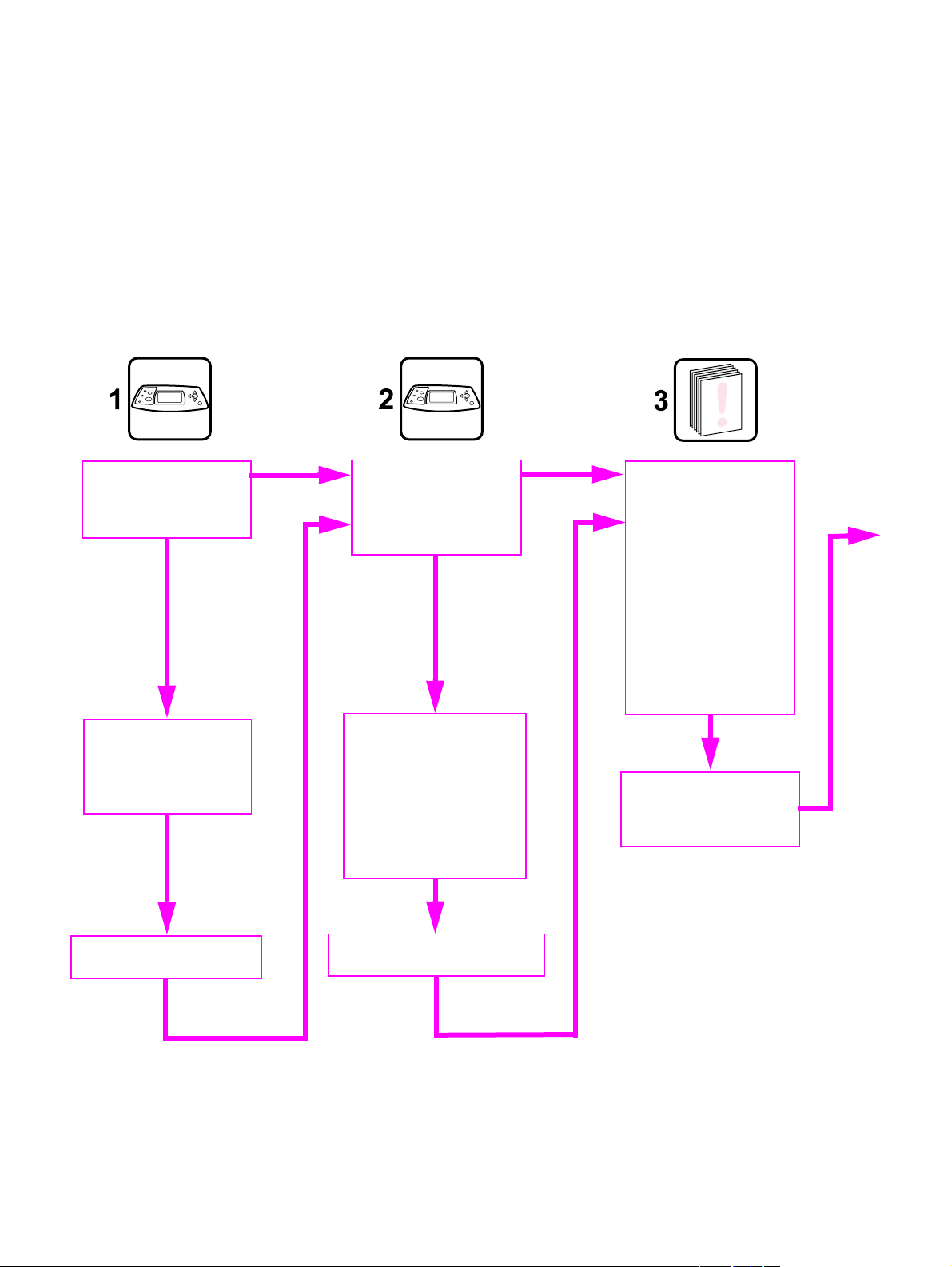
Troubleshooting flowchart
The flowchart on these two pages highlights the general processes you can use to isolate and
solve printer hardware problems quickly.
Each heading depicts a major troubleshooting step. A "yes" answer to a question allows you to
proceed to the next major step.
A "no" answer indicates that additional testing is needed. Proceed to the appropriate section in
this chapter, and follow the instructions there. After completing the instructions, proceed to the
next major step in this troubleshooting flowchart.
Power on
Is the printer on and does
a readable message
appear?
NO
Power-on Checks
Follow the power-on
troubleshooti ng ch ecks.
See “Po w e r-on ch ecks”
on page 236.
YES
Control-Panel display
Does the message
READY, OFFLINE, or
POWERSAVE appear on
the control-panel display?
NO
Error messages appears
Use the error-message
tables in this chapter to
understand the message
and correct the problem.
See “Alphabetical printer
messages” on page 258
and “Numerical printer
messages” on page 274.
YES
Event log
Print an event lo g. If error
messages appear on the
control-panel display
when you try to see or
print the event log, see
“Alphabetical printer
messages” on page258
and “Numerical printer
messages” on page274.
If the event log does not
print, see “Engine test
page” on page 254.
Evualuate the event log
After evalu ating the event
log, go to step 4. See
figure 200 on page 235.
Display panel is functional
Proceed to step 2.
Errors have been corrected
Proceed to step 3.
Figure 199. Troubleshooting flowchart (1 of 2)
234 Troubleshooting Q2431-90912
Page 9
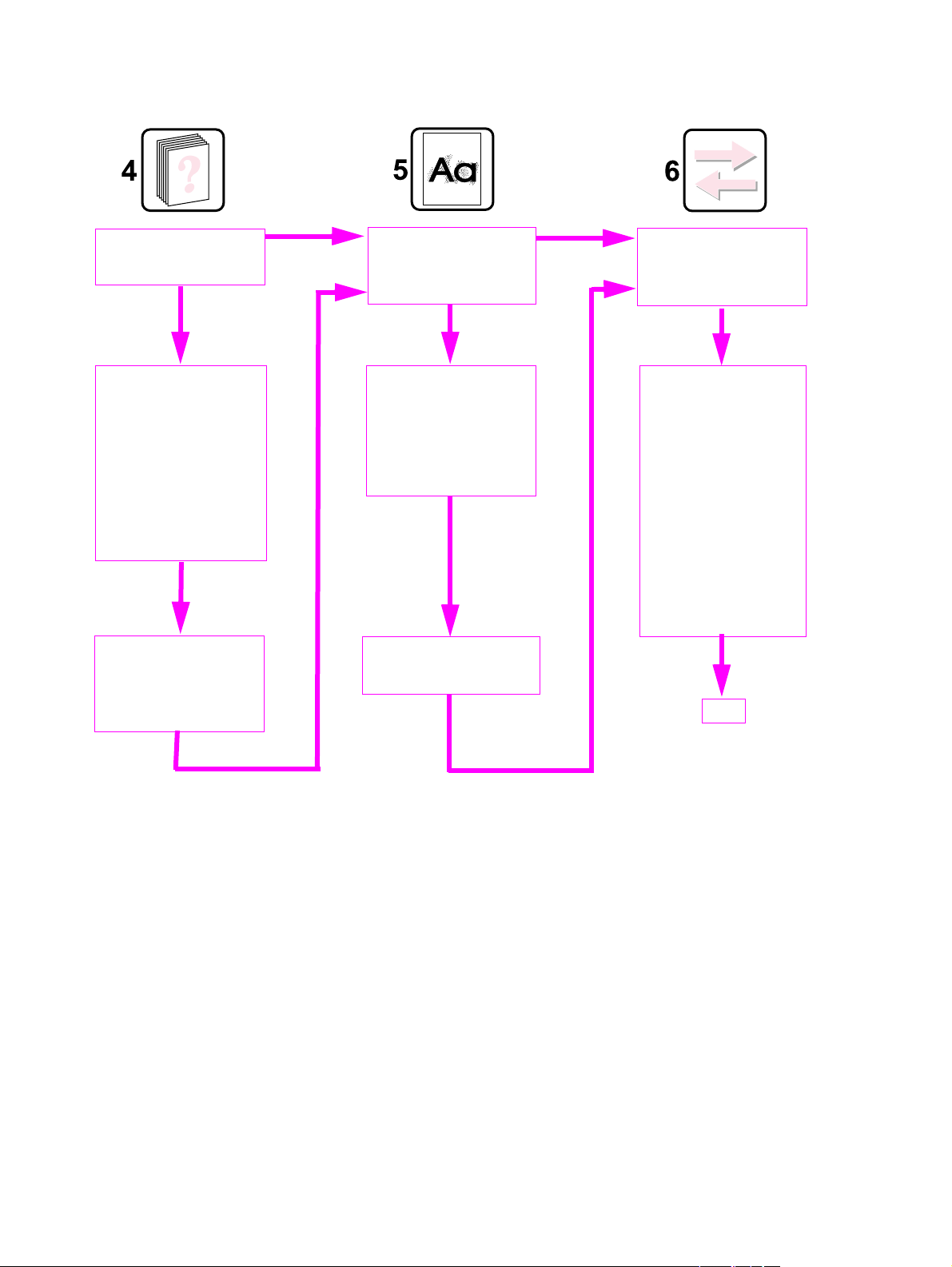
Troubleshooting flowchart (continued)
Information pages
Can you print a
configuration page?
NO
Configuration page
Print an eve nt log. I f error
messages appear on the
control-panel display
when you try to see or
print the configuration
page, see “Alphabetical
printer messages” on
page 258 and “Numerical
printer messages” on
page 274.
Evaluate th e
configuration page
After evaluating the
configuration page, go to
step 5.
YES
Image quality
Does the print quality
meet customer
requirements?
NO
Image defects
Compare the images with
the sample def e cts i n th e
image defect tables. See
“Image-formation
troubleshooting” on
page 306.
Image defects correcte d
After meeting print quality
requirements, go to step 6.
YES
Interface
Can the customer print
successfully from t he host
computer?
NO
Perform corrective
actions
Repeat control-panel
error message actions
and image defect
corrective act ions un til all
errors and image defects
are corrected.
See “Alphabetical printer
messages” on page 258
and/or “Numerical p rinter
messages” on page 274
and/or “Image-formation
troubleshooting” on
page 306.
YES
END
Figure 200. Troubleshooting flowchart (2 of 2)
Q2431-90912 Chapter 7 Troubleshooting 235
Page 10

Power-on checks
The basic printer functions should start up as soon as the printer is plugged into an electrical wall
receptacle and the power switch is pushed to the on position.
Overview
Turn on the printer power. If the control-panel display remains blank, random patterns appear, or
asterisks remain on the display, perform power-on checks to locate the cause of the problem.
During normal printer operation, the main cooling fan begins to spin briefly after the printer power
is turned on. Place your hand over the holes in the left-side cover. If the fan is operating, you will
feel a slight vibration and feel air passing into the printer. You can also lean close to the printer
and hear the fan operating. When this fan is operational, the dc side of the power supply is
properly functioning.
After the fan is operating, the main motor turns on (unless the top cover is open, or a jam
condition is sensed, or the paper path sensors are damaged). You should be able to visually and
audibly determine if the main motor is turned on.
If the fan and main motor are operating properly, the next troubleshooting step is to separate
print engine, formatter, and control-panel problems. Perform an engine test (see “Engine test
page” on page 254). If the formatter is damaged, it might interfere with the engine test. If the
engine test page does not print, try removing the formatter and performing the engine test again.
If the engine test is then successful, the problem is almost certainly with the formatter, the control
panel, or the cable that connects them.
If the printer control panel is blank when you turn on the printer, check the following items.
1. Make sure that the printer is plugged into an active electrical outlet that delivers the correct
voltage.
2. Make sure that the on/off switch is in the on position.
3. Make sure that the fan runs briefly, which indicates that the power supply is operational.
4. Make sure that the control panel display wire-harness is connected. See the hint in the
procedure for “Top cover” on page 146.
5. Make sure that the firmware DIMM and the formatter are seated and operating properly . See
“Firm ware DIMM” on page 160.
6. Remove any HP Jetdirect or other EIO cards, and then try to turn the printer on again.
Note If the printer control-panel display is blank, but the main cooling fan runs briefly after the printer
power is turned on, try printing an engine test page to determine whether the problem is with the
control-panel display, formatter, or other printer components. See “Engine test page” on
page 254.
If the main cooling fan is not operating, check the following items.
7. Check the fuse on the power supply (location FU2; near the power switch) to make sure that
it is not open.
8. If necessary, replace the power supply. See “Power supply” on page 188.
9. If necessary, replace the DC controller PCA. See “DC controller PCA” on page 181.
Note It is important to have the printer control panel functional as soon as possible in the troubleshooting
process so that the control-panel display can be used to help locate printer errors.
236 Troubleshooting Q2431-90912
Page 11

Table 38. Power-on defect or blank display
Problem Action
The power cord is not plugged into the wall
receptacle and connected to the printer.
Make sure that the power cord is firmly plugged into the
wall receptacle and connected to the printer.
Proper power is not available. Measure the voltage at the outlet. If necessary, plug the
power cord into another circuit outlet.
The power switch is off. Set the switch to the on position. You should hear the
switch toggle. If the front right-side cover has been
remove d rece ntly, make sure that the rod conne cting the
power supply switch moves as you toggle the switch.
See the reinstall note in “Right-side cover” on page 149.
If the printer still does not turn on, the power switch
might be defective.
1. Remove the power supply.
2. Measure the resistance between the two terminals
of the power switch (SW1) by applying the tester
probes to the terminals. The resistance must be low
(under 1 KΩ) when the pow er i s t urned on, an d h igh
(over 6 MΩ) when the switch is turned off.
3. Replace the power supply, if necessary.
The overcurrent/overvoltage detection circuit is
activated.
Wait f or mo re than tw o min utes bef ore turning the pri nter
back on.
A fuse is blown. 1. Check the fuses (FU1 and FU2) on the power
supply.
2. Replace the power supply if necessary.
The main cooling fan (located on the left side of
the printer) does not turn on when the printer is
started.
An operational fan indicates the following:
● AC power is present in the printer.
● DC power supply is functional (24V, 5V, and 3.3V are
being generated).
● The DC controller’s microprocessor is functional.
If the fan is not working:
1. Turn the printer off and remove the formatter.
Disconnect the optional accessories.
2. Turn the printer on and check the fan again.
If the fan is still not working:
1. Verify that the fan is connected to the power supply.
2. Replace the f an. S ee “Mai n cooling fa n (left side )” on
page 168.
3. Replace the power supply assembly. See
“Power
supply” on page 188.
4. Replace the DC controller. See “DC controller PCA”
on page 181
Note:
The fan only operat es during the initi al startup and whil e
printing, and when the temperature inside the printer is
too high. If the temperature is too high, the fan turns on
to cool the inside of the printer.
Q2431-90912 Chapter 7 Troubleshooting 237
Page 12

Table 38. Power-on defect or blank display (continued)
Problem Action
The fan works, but the control-panel display is
blank.
1. Print an engine test. “Engine test page” on page254
2. If the engine test is successful, perform the following
steps in order.
● Reseat the control panel and formatter c onnec tor. See
“Control-panel assembly” on page157 and “Formatter
assembly” on page 161.
● Replace the control panel cable. See “Control-panel
assembly” on page 157.
● Replace the control panel assembly. See
“Control-panel assembly” on page157.
● Replace the firmware DIMM. See “Firmware DI MM” on
page 160.
● Replace the formatter. See “Formatter assembly” on
page 161.
3. If the engine test is not successful, remove the
formatter and attempt to perf orm the engine test aga in. If
the engine test is succes sful with t he fo rmatter remov ed,
replace the formatter. See “Formatter assembly” on
page 161. If the test is not successful with the formatter
removed, replace the DC controller PCA. See
“DC controller PCA” on page 181.
238 Troubleshooting Q2431-90912
Page 13

Troubleshooting tools
Press the SELECT ( ) button to open the menus. Use the UP ARROW ( ) button or the DOWN
A
RROW ( ) button to scroll through the menus that appear. For more information about control
panel menus, see “Control-panel menus” on page 39. The high-level menus appear in the
following order:
● RETRIEVE JOB ● INFORMATION
● PAPER HANDLING ● CONFIGURE DEVICE
● DIAGNOSTICS ● SERVICE
Information pages
1. Press the SELECT ( ) button to open the MENUS.
2. Press the D
3. Press the S
4. Press the D
OWN ARROW button to scroll to INFORMATION.
ELECT ( ) button to select INFORMATION.
OWN ARROW ( ) button to scroll to a listed information page. The following
pages are available:
● Menu map
● Configuration
● Supplies status
● File directory
● Usage page
● PCL and PS font list
5. Press the S
ELECT ( ) button to select and print the selected information page.
The informational pages for the printer are also available in the embedded Web server. Not all
information pages are discussed in detail in this manual. For more information, see the
HP LaserJet 4200/4300 Use Guide. The information pages include the following.
● Menu map: A menu map shows how individual items are configured within the
high-level (user-set values) menus. The last page of the menu map series describes
instructions about how to use the control-panel buttons. Print a menu map before
changing printer settings or before replacing the formatter assembly.
● Configuration page: The configuration page lists printer configuration information.
For example, the printer serial number and tray size settings appear on the
configuration page. Print a configuration page before servicing the printer to help
restore values after servicing the printer.
● Supplies status: This page shows the levels of the printer supplies, a calculation of
the number of pages that can be printed before the supplies are replaced, and
cartridge-usage information.
● File directory: This page provides information about files on the ramdisk or installed
EIO disk drives and flash DIMMs if those memory accessories are installed.
● Usage page: The usage page is only available if an optional hard disk is installed. It
provides useful accounting information (for example, the number of pages of various
paper sizes that have been used and data that can be used to calculate toner
usage).
● PS or PCL font list: This page lists the fonts that are installed in the printer
memory. This page also lists fonts on an optional hard-disk accessory or flash DIMM
if those me mory accessories are installed.
Q2431-90912 Chapter 7 Troubleshooting 239
Page 14
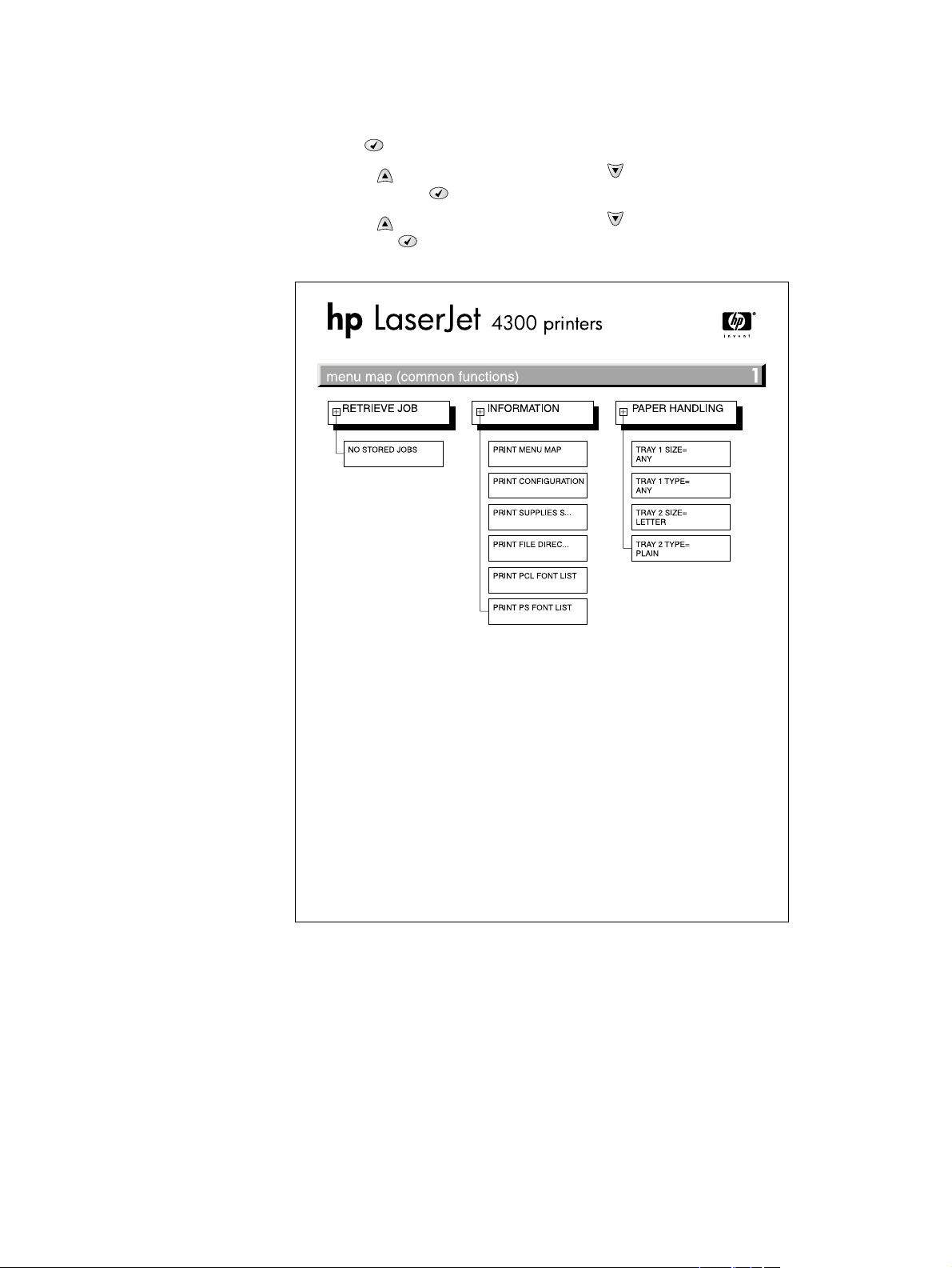
Menu map
Use the menu map to help navigate the printer submenus and select configuration settings.
Printing a menu map is very helpful when you are changing numerous printer settings.
1. Press the S
2. Use the U
P ARROW ( ) button or the DOWN ARROW ( ) button to scroll to INFORMATION,
and then press the S
3. Use the U
P ARROW ( ) button or the DOWN ARROW ( ) button to scroll to MENU MAP, and
then press the S
ELECT ( ) button to open the menus.
ELECT ( ) button.
ELECT ( ) button.
Figure 201. Sample menu map page
240 Troubleshooting Q2431-90912
Page 15
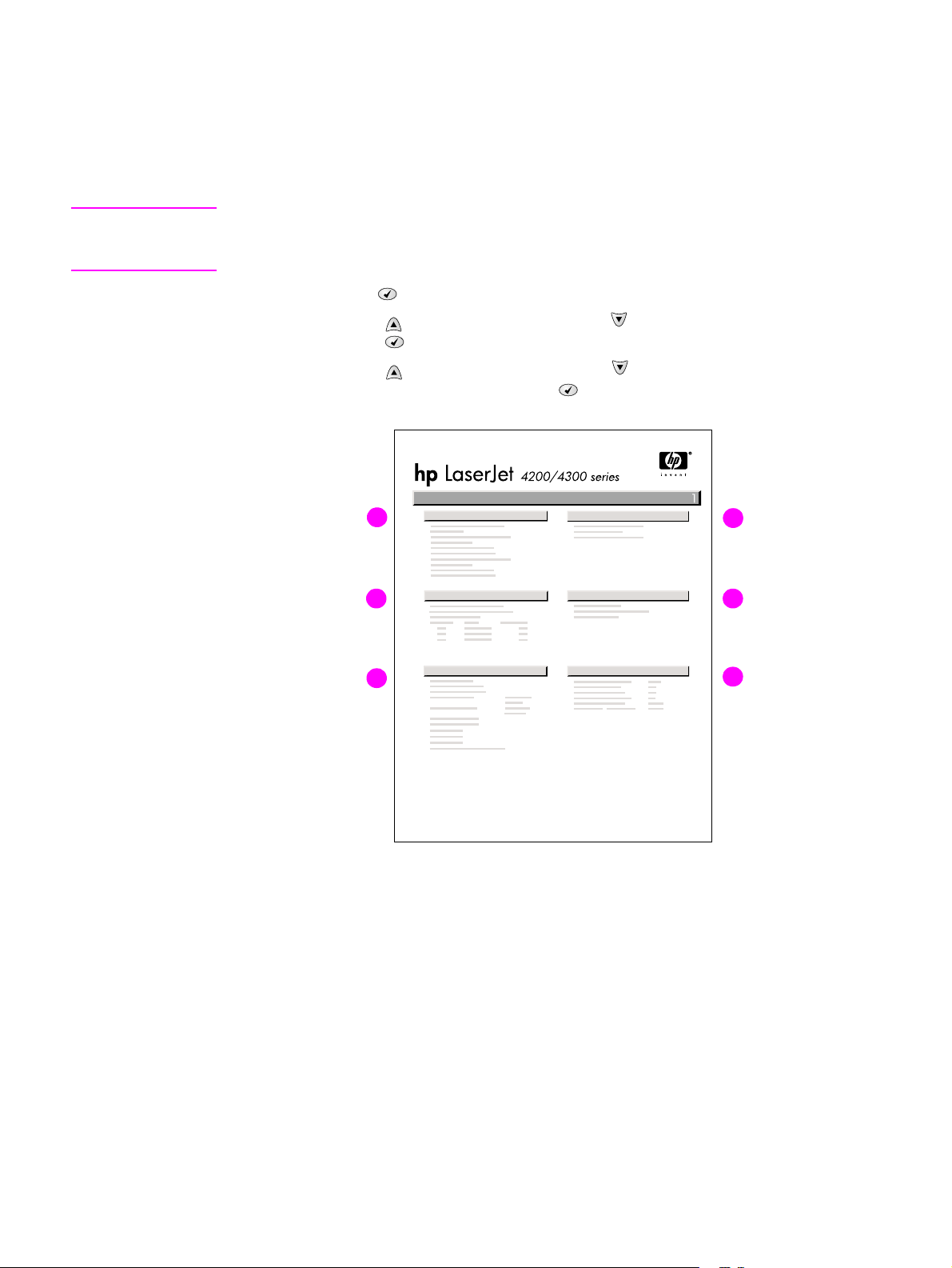
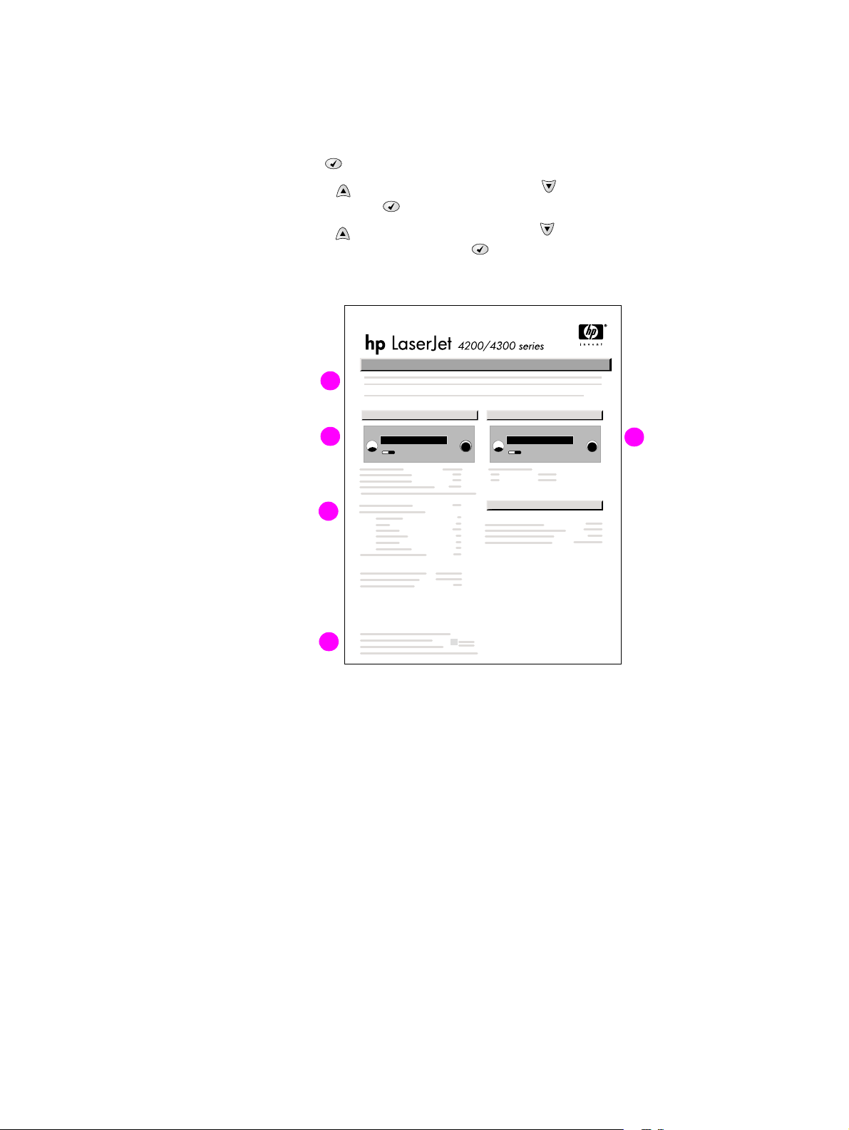
Configuration page
Use the configuration page to view current printer settings, to help troubleshoot printer problems,
or to verify installation of optional accessories, such as memory (DIMMs), trays, and printer
languages. The content of the configuration page varies, depending on the options currently
installed in the printer. To decode the service identification information on the configuration page,
see “Converting the Service ID to an actual date” on page 250.
Note If an HP Jetdirect print server is installed, an HP Jetdirect configuration page prints as well.
HP LaserJet 4200n/tn/dtn/dtns/dtnsL and 4300n/tn/dtn/dtns/dtnsL printers come with an
HP Jetdirect printer server installed.
1. Press the S
2. Use the
then press S
3. Use the
ELECT ( ) button to open the menus.
UP ARROW ( ) button or the DOWN ARROW ( ) button to scroll to INFORMATION, and
ELECT ().
UP ARROW ( ) button or the DOWN ARROW ( ) button to scroll to PRINT
CONFIGURATION, and then press the S
A
B
C
ELECT ( ) button.
D
E
F
Figure 202. Configuration page
A. Printer Information Lists the serial number, page counts, printer number
(DC controller revision), service ID (see “Service ID” on
page 250), and other printer information
B. Event log Lists the three most recent event log entries (numeric codes for
printer events)
C. Personalities and options Lists installed personalities and options (such as PS and PCL
languages) and installed optional DIMM(s) or EIO accessories
D. Memory Lists the printer memory and I/O buffering and resource saving
information
E. Security Lists the status of the control-panel lock, control-panel
password, and any disk drives
F. Paper trays and options Lists the size and type settings for all trays and lists optional
paper-handling accessories that are installed
Q2431-90912 Chapter 7 Troubleshooting 241
Page 16
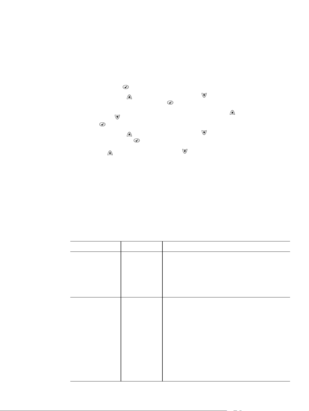
Supplies status page
Use the supplies status page to obtain information about the print cartridge installed in the
printer, the amount of life left in the print cartridge, and the number of pages and jobs that have
been processed. The page also lets you know when you should perform the next preventative
maintenance.
1. Press the S
2. Use the U
and then press the S
3. Use the U
ELECT ( ) button to open the menus.
P ARROW ( ) button or the DOWN ARROW ( ) button to scroll to INFORMATION,
ELECT ( ) button.
P ARROW ( ) button or the DOWN ARROW ( ) button to scroll to PRINT SUPPLIES
STATUS PAGE, and then press the S
A
B
C
ELECT ( ) button.
E
Figure 203. Supplies status page
A. Supplies website Lists the website for ordering supplies over the Internet
B. Cartridge information Provides information about the amount of toner available in the
C. Printing statistics Lists statistics about the total number of pages and jobs that
D. Recycle website Lists the website for information about returning used HP print
E. Maintenance kit gauge Shows a gauge to let you know the remaining life of the
D
print cartridge, and shows the print-cartridge part number and
estimated pages that can be printed for the amount of toner in
the cartridge
have been processed using this print cartridge, the first and last
use date for the cartridge, and the print cartridge serial number
cartridges
maintenance kit components
242 Troubleshooting Q2431-90912
Page 17

Embedded Web server
When the printer is directly connected to a computer, the embedded Web server is supported for
Windows 95 and later. In order to use the embedded Web server with a direct connection, you
must choose the Custom installation option when you install the printer driver. Select the option
to load Printer Status and Alerts. The proxy server is installed as part of the Printer Status and
Alerts software.
When the printer is connected to the network (by using a HP Jetdirect print server EIO card), the
embedded Web server is automatically available.
Use the embedded Web server to view printer and network status and to manage printing
functions from your computer instead of from the printer control panel. The following are
examples of what you can do through the embedded Web server:
● view printer status information
● specify the type of paper that is loaded in each tray
● determine the remaining life for all supplies and order new supplies
● view and change tray configurations
● view and change the printer control panel menu configurations
● view and print internal pages
● receive notification of printer and supplies events
● view and change the network configuration
To use the embedded Web server, you must have Microsoft Internet Explorer 4 and later or
Netscape Navigator 4 and later. The embedded Web server works when the printer is connected
to an IP-based network. The embedded Web server does not support IPX-based printer
connections. You do not have to have Internet access to open and use the
embedded Web server.
Gaining access to the embedded Web server
In a supported Web browser on your computer, type the IP address for the printer. (To find the
IP address, print a configuration page.)
Note After you navigate to the URL, you can bookmark it so that you can return to it quickly in the future.
The embedded Web server has three tabs that contain settings for and information about the
printer: the Information tab, the Settings tab, and the Network tab. Click the tab that you want
to view. See the following sections for more information about each tab.
Q2431-90912 Chapter 7 Troubleshooting 243
Page 18

Informa tion tab
The Information tab contains the following pages.
● Device Status. Shows the printer status and the life that remains in HP supplies
(0 percent represents that a supply is empty). This page also shows the type and
size of print media set for each tray. To change the default settings, click Change
Settings.
● Configuration page. Shows the information that is contained on the printer
Configuration page.
● Supplies Status. Shows the life that remains in HP supplies (0 percent represents
that a supply is empty). This page also provides supplies part numbers. To order
new supplies, click Order Supplies in the Other Links area on the left side of the
window. To visit this or any website, you must have Internet access.
● Event log. Shows a list of all printer events and errors.
● Usage page. Shows a summary of the number of pages the printer has printed,
grouped by size and type (this page is only available if an optional hard disk is
installed).
● Device Information. Shows the printer network name, address, and model
information. To change these entries, click Device Information on the Settings tab.
Settings tab
Use the Settings tab to configure the printer from your computer. The Settings tab can be
password protected. If the printer is on a network, always consult with the network administrator
before changing settings on this tab.
The Settings tab contains the following pages.
● Configure Device. Use this page to configure all the printer settings. This page
contains the traditional printer menus: Information, Paper Handling, Configure
Device, and Diagnostics.
● Alerts. (On networks only.) Use this page to establish e-mail alerts for various
printer and supplies events.
● E-mail. (On networks only.) Use this page in conjunction with the Alerts page to set
up incoming and outgoing e-mail, as well as to establish e-mail alerts.
● Security. Use this page to set a password that must be typed to gain access to the
Settings and Networking tabs. Also use it to enable and disable certain features of
the embedded Web server.
● Other Links. Use this page to add or customize a link to another website. The link
you establish appears in the Other Links area on all embedded Web server pages.
The following permanent links always appear in the Other Li nks area: HP Instant
Support™, Order Supplies, and Product Support.
● Device Information . Use this page to name the printer and assign an asset number
to it. Use the name and e-mail address for the primary contact who will receive
information about the printer.
● Language. Use this page to specify the language in which the
embedded Web server information appears.
Networking tab
The network administrator uses this tab to control network-related settings for the printer when it
is connected to an IP-based network. This tab does not appear if the printer is directly connected
to a computer, or if the printer is connected to a network with anything other than an HP Jetdirect
print server card.
244 Troubleshooting Q2431-90912
Page 19

Other links
This section of the embedded Web server contains links that connect you to the Internet. You
must have Internet access in order to use any of these links. If you use a dial-up connection and
did not connect when you first opened the embedded Web server, you must connect before you
can visit these Web sites. Connecting to the Internet might require that you close your Web
browser and reopen it.
● HP Instant Support™ connects to the HP website to help you find solutions. This
service analyzes your printer error log and configuration information to provide
diagnostic and support information that is specific to your printer.
● Order Supplies connects to the HP website so you can order genuine HP supplies,
such as print cartridges and paper.
● Product Support connects to the support site for the HP LaserJet 4200/4300
printer, where you can search for help regarding general topics.
Printer Status and Alerts software
Printer Status and Alerts is supported only for Windows 95 and later versions.
The Printer Status and Alerts software is available to users of both networked and directly
connected printers. To use Printer Status and Alerts software with a directly connected
computer, you must select the Custom installation option when you install the printer driver, and
then select the option to install Printer Status and Alerts. For network connections, Printer Status
and Alerts is installed automatically with the Typical software installation option.
Use this software to view the embedded Web server information for a particular printer. Printer
Status and Alerts also generates messages on the computer that explain the status of the printer
and print jobs. Depending on how the printer is connected, you can receive different messages.
● Networked printers. You can receive regular job status messages that appear
every time a print job is sent to the printer or every time the print job is complete.
You can also receive alert messages. These messages appear when you are
printing to a particular printer if that printer experiences a problem. In some cases,
the printer can continue to print (such as when a tray that is not being used is open,
or a print cartridge is low). In other cases, a problem might prevent the printer from
printing (such as when paper is out, or a print cartridge is empty).
● Directly connected printers. You can receive alert messages that appear when the
printer experiences a problem but can continue printing or a problem that prevents it
from printing. You can also receive messages that indicate that the print cartridge is
low.
You can set alert options for a single printer that supports Printer Status and Alerts, or you can
set alert options for all printers that support Printer Status and Alerts. For networked printers,
these alerts only appear for your jobs.
Even if you set alert options for all printers, not all of the selected options will apply to all printers.
For example, when you select the option to notify you when the print cartridges are low, directly
connected printers that support Printer Status and Alerts generate a message when the print
cartridges are low. However, none of the networked printers generate this message unless the
alert affects a user-specific job.
Q2431-90912 Chapter 7 Troubleshooting 245
Page 20

To select status messages
1. Open Printer Status and Alerts in one of these ways:
• Double-click the Printer Status and Alerts tray icon, which is near the clock in the Tray
Manager.
• On the Start menu, point to Programs, point to Printer Status and Alerts, and click
Printer Status and Alerts.
2. Click the Options icon on the left side of the window.
3. In the For field, select the printer driver for this printer, or select All Printers.
4. Clear the options for the messages that you do not want to appear, and select the options for
the messages that you do want to appear.
5. In Status check rate, select how frequently you want the software to update the
printer-status information that the software uses to generate the messages. The status
check rate might not be available if the network administrator has restricted the rights to this
function.
To view status messages and informat ion
On the left side of the window, select the printer for which you want to see information. The
information that is provided includes status messages, supplies status, and printer capabilities.
You can also click the job history (clock) icon at the top of the window to view a list of previous
jobs that were sent to the printer from your computer.
246 Troubleshooting Q2431-90912
Page 21
Control-panel menus
Use the control-panel menus to control various printer functions. For example, you can use the
Resets submenu to quickly reset and restore most of the factory default printer settings. Not all
of the available menus are described in this manual. For more information about control-panel
menus, see “Control-panel menus” on page 39.
Using control-panel menus
1. Press the SELECT ( ) button to open the menus.
2. Use the U
you want, and then press the S
3. Some menus might have several submenus. Use the U
D
OWN ARROW ( ) button to scroll to the submenu item that you want, and then press the
S
ELECT ( ) button.
4. Use the U
then press the S
P ARROW ( ) button or the DOWN ARROW ( ) button to scroll to the menu that
ELECT ( ) button.
P ARROW ( ) button or the
P ARROW ( ) button or the DOWN ARROW ( ) button to scroll to the setting, and
ELECT ( ) button. An asterisk (*) appears next to the selection on the
display, indicating that it is now the default. Some settings change rapidly if the
U
P ARROW ( ) button or the DOWN ARROW ( ) button is held down.
5. Press P
AUSE/RESUME to close the menu.
Resets submenu
To find the Resets submenu, use the control panel to open the Configure Device menu (see
“Control-panel buttons” on page 37 and “Configure Device menu” on page 44). Items on the
Resets submenu are used to return settings to the defaults and to change settings such as
PowerSave.
The following section lists the settings and their possible values in the Resets submenu. The
default value for each setting is the one that has an asterisk (*) next to it.
Table 39. Resets submenu
Item Values Explanation
RESTORE FACTORY
SETTINGS
POWERSAVE OFF
No values
available.
*ON
Performs a simple reset and restores most of the factory
(default) settings. This item also clears the input buffer for
the activeI/O. Restorin g f actory setting s does not aff ect the
network parameter settings on the optional HPJetdirect
print server.
CAUTION
Restoring memory during a print job cancels the print job.
Turns the PowerSave mode on or off. The PowerSave
mode affects the printer in two ways:
● minimizes the amount of power that the printer consumes
when it is idle
● reduces wear on the electronic components in the printer
(for ex ample , it turns off the displa y bac klight, alth ough the
display can still be read)
The printer automatically leaves the PowerSave mode
when you send a print job, press a printer control panel
button, open a tray, or open the top cover.
You can set the amount of time t hat the printer re mains idle
before it enters the PowerSave mode. For more
information see “System Setup submenu” on page 49.
Q2431-90912 Chapter 7 Troubleshooting 247
Page 22
Diagnostics menu
Administrators can use this menu to isolate parts and to troubleshoot jam and print-quality
issues.
The following section lists the settings and their possible values in the Diagnostics menu. The
default value for each setting is the one that has an asterisk (*) next to it.
Table 40. Diagnostics menu
Item Values Explanation
PRINT EVENT LOG No values
available.
SHOW EVENT LOG No values
available.
PAPER PATH TEST
● PRINT TEST
PAGE
● SOURCE
● DESTINATION
● DUPLEX
● COPIES
No values
available.
● PRINT TEST PAGE Press the SELECT () button to start the paper-path test
● SOURCE
ALL TRAYS
TRAY 1
*TRAY 2
TRAY [N]
● DESTINATION
ALL BINS
*STANDARD OUTPUT
OPTIONAL BIN 1
Press the SELECT () button to generate a list of the
50 most recent entries in the event log. The printed event
log shows the error number, page count, error c ode, and
description or personality that was in use when the event
occurred.
the UP ARROW ( ) button or the
Use
DOWN ARROW ( ) button to scroll through the event log
contents.
Generate a test page which is useful for testing the paper-
handling features of the printer.
using the source (tray), destination (output bin), duplex,
and number o f copies settings that you set in the other
items on the Paper Path Test menu. Set the other items
before choosin g PRINT TEST PAGE.
Select the tray f or the pap er path tha t y ou wa nt to test. You
can select any tray that is installed. Select ALL TRAYS to
test the paper path for eve ry tra y. (Paper must be lo aded i n
the selected tray s.)
Select the output bin for the paper path that you want to
test. You can select any output bin that is installed.
Optional bins (stacker or stapler/stacker bin) must also be
correctly configured. Select ALL BINS to test the paper
path for every bin.
● DUPLEX
*OFF
ON
● COPIES
*1
10
50
Determine whether or not the paper goes through the
duplexer during the paper path test. This item is available
only if the duplexer is installed.
Set how many sheets of paper are used from each tray
during the paper-path test. If you are testing the stapling
function of the optional stapler/stacker (DESTINATION item
OPTIONAL BIN 1), you must select 10 copies.
100
500
248 Troubleshooting Q2431-90912
Page 23

Service menu (service PIN codes)
Authorized HP service technicians can use this menu to gain access to printer settings that are
reserved for service personnel. The service menu is protected by use of a personal identification
number (PIN). When you select SERVICE from the list of menus, you are prompted to type an
eight-digit PIN code.
Note The printer automatically exits the service menu after about one minute if no menu items are
selected or changed.
Use the PIN code 11420002 for the HP LaserJet 4200 product and the PIN code 11430002
for the HP LaserJet 4300 product.
1. Press the Select ( ) button to open the menus. Use the Up Arrow ( ) button or the
Down Arrow ( ) button to scroll to SERVICE, and then press the Select ( ) button.
2. Press the Up Arrow ( ) button or the Down Arrow ( ) button until the first digit of the PIN
code appears. Press the Select ( ) button to save that digit. Repeat this selection
procedure until you have typed the entire eight-digit PIN code. You can use the
Left Arrow ( ) button to return to a PIN digit. When the last digit is saved, the service
submenu appears on the control-panel display.
3. Use the Up Arrow ( ) button or the Down Arrow ( ) button to scroll to the service-menu
item that you want, and then press the Select ( ) button.
● Clear event log. Select this item to clear (resets to zero) the internal event log.
● Total page count. Select this item to set the total number of pages that have been
printed to-date. Typically this is only required when a new formatter is installed.
● Maintenance count. Select this item to set the number of pages that have been
printed since the last maintenance kit was installed or the total number of pages that
have been printed on this printer if a maintenance kit has not yet been installed
(during the first 200,000 pa ges ) .
● Maintenance interval. Select this item to specify the number of pages that can be
printed before a maintenance-kit-required message appears on the control-panel
display to indicate that a maintenance kit is required.
● Serial number. Select this item to update the serial number if you replace the
formatter.
● Service ID. Select this item to specify the date when the printer was first used,
rather than the date when a replacement formatter is installed. See “Restoring the
Service ID” on page 250.
● Cold reset. Select this item to reset the default paper size when you replace the
formatter.
factory settings (see “R e se ts sub menu ” on page 247). Use this item to restore the
initial default factory settings for the paper size. When you replace a formatter in a
country/region that uses A4 as the standard paper size, use this item to reset the
default paper size to A4. Letter and A4 are the only cold reset values available.
When you perform a cold reset (see “Cold reset” on page 251) or restore
Q2431-90912 Chapter 7 Troubleshooting 249
Page 24

Service ID
This information appears on the configuration page (see “Configuration page” on page 241),
which eliminates the need for customers to keep paper receipts for proof of the warranty.
Because the printer does not have an internal clock, the availability of the service ID date
depends on the printer being connected to a source that can provide the date, in this case a time
server on the same network as the printer. When the printer is not connected to a date source,
the service ID is not available, and 00000 appears on the configuration page.
Restoring the Service ID
If you replace the formatter, the date is lost. Use this menu item to reset the value to the date that
the printer was first used. The date format is YYDDD. Use the following procedure to calculate
the date.
1. To calculate YY, subtract 1990 from the calendar year. For instance, if the printer was first
used in 2002, calculate YY as follows: 2002 – 1990 = 12 (YY = 12).
2. To calculate DDD, use the following formula:
30 (calendar month – 1) + calendar day = DDD. If the calendar day is 31, use 30 instead.
For instance, if the printer was first used on October 17, calculate DDD as follows:
a. Subtract 1 from 10 (October is the tenth month of the year): 10 – 1=9.
b. Multiply 9 by 30: 9 x 30 = 270.
c. Add 17 to 270: 270 + 17 = 287 (DDD = 287).
Converting the Service ID to an actual date
You can use the printer’s Service ID number to determine whether the printer is still under
warranty. Use the following procedure to convert the Service ID into the installation date.
1. Add 1990 to YY to determine the actual year that the printer was installed.
2. Divide DDD by 30 and add 1 to the remainder. The total is the month.
3. The remainder from the calculation in step 2 is the day of the month.
Using the Service ID 12287 as an example, the date conversion is as follows:
● 12 + 1990 = 2002, so the year is 2002.
● 287 divided by 30 = 9 with a remainder of 17. Add 1 to 9 to get 10 so the month is
October.
● The remainder (from the above calculation) is 17, so that is the day of the month.
● The complete date is 17-October-2002.
A 6-day grace period is built into the date system.
250 Troubleshooting Q2431-90912
Page 25

Printer resets and power-on modes
Cold reset
A cold reset unlocks menus that have been previously locked and sets all control panel menu
items (including EIO settings) back to the factory defaults. However, it does not clear the values
in the service menu (such as the serial number and page counts).
Note Before performing a cold reset, print a menu map and a configuration page (see “Menu map” on
page 240 and “Configuration page” on page 241). Use the information on the configuration page
to reset any customer-set printer configuration values that the cold reset procedure changes.
To perform a cold reset
1. Turn the printer power off.
2. Hold down the S
down the S
ELECT ( ) button, and then turn the printer power on. Continue holding
ELECT ( ) button until all three printer control-panel lights flash once and then
remain on. This might take up to 10 seconds.
3. After the message SELECT LANGUAGE appears on the display, press the U
button or the D
4. Press the S
OWN ARROW ( ) button until COLD RESET is highlighted.
ELECT ( ) button. The printer performs a cold reset and then continues its
P ARROW ()
power-on sequence.
5. Check all I/O settings and reset any customer-set printer configuration values.
NVRAM initializatio n
CAUTION Initializing the NVRAM resets the serial number, the event log, the page counts, and the EIO card
(Initializing the NVRAM will reset service menu values to factory defaults). Use the service menu
to restore the serial number and page counts. Also reconfigure any computers that print to this
printer so that the computers can recognize the printer. Initialize the NVRAM only when absolutely
necessary. In most situations, use a cold reset rather than a NVRAM initialization to reset printer
settings (this will retain the values in the service menu).
Note Before performing a NVRAM initialization, print a menu map and a configuration page (see “Menu
map” on page 240 and “Configuration page” on page 241). Use the information on the
configuration page to reset any customer- s et pri nte r co nfi guration values that the NVRAM
initialization procedure changes. Take special note of the total page count, maintenance count,
and the serial number.
To initialize NVRAM
1. Remove any installed accessories (for example, a stapler/stacker).
2. Turn the printer power off.
3. Hold down the D
holding down the D
once and then remain on. This might take up to 10 seconds.
4. Press the U
5. Press the P
6. Press the U
7. Press the S
power-on sequence.
Q2431-90912 Chapter 7 Troubleshooting 251
OWN ARROW ( ) button, and then turn the printer power on. Continue
OWN ARROW ( ) button until all three printer control panel lights flash
P ARROW ( ) button.
AUSE/RESUME button. The display should show SKIP DISK LOAD.
P ARROW ( ) button until NVRAM INIT is highlighted.
ELECT ( ) button. The printer initializes NVRAM and then continues its
Page 26

Hard-disk initialization
CAUTION A hard-disk initialization erases and reformats the printer hard disk. Perform a hard disk
initialization only if an error code on the control panel indicates an EIO disk error. Always try
initializing the hard disk before replacing it.
Note Before performing a hard-disk initialization, print a menu map and a configuration page (see “Menu
map” on page 240 and “Configuration page” on page 241). Use the information on the
configuration page to reset any customer-set printer configuration values that the hard disk
initialization procedure changes.
To initialize the hard disk
1. Turn the printer power off.
2. Hold down the P
down the P
AUSE/RESUME button, and then turn the printer power on. Continue holding
AUSE/RESUME button until all three printer control panel lights flash once and then
remain on. This might take up to 10 seconds.
3. Press the B
4. Press the S
ACK ARROW ( ) button. The display should show INITIALIZE DISK.
ELECT ( ) button. The printer initializes the hard disk and continues its power-on
sequence.
Power-on bypass
When the power is turned on the printer begins the power-on sequence. By performing a
power-on bypass, you can cause the printer to resume the power-on sequence but not to
recognize any installed EIO hard disk (skip disk load procedure). This can be helpful in isolating
EIO hard-disk errors.
You can also resume the power-on sequence but make the printer continuously print
configuration pages until the Pause/Resume button is pressed (self test procedure). This can be
helpful if you need to verify the printer components that are installed by reviewing the information
found on the configuration page, but the you cannot open the menus to print a configuration
page.
Skip disk load
1. Turn the printer power off.
2. Hold down the D
holding down the D
OWN ARROW ( ) button, and then turn the printer power on. Continue
OWN ARROW ( ) button until all three printer control panel lights flash
once and then remain on. This might take up to 10 seconds.
3. Press the U
4. Press the U
P ARROW ( ) button followed by the Pause/Resume button.
P ARROW ( ) button or the DOWN ARROW ( ) button until SKIP DISK LOAD is
highlighted.
5. Press the S
ELECT ( ) button. The printer continues the power-on sequence but ignores an
installed EIO hard disk.
252 Troubleshooting Q2431-90912
Page 27

Self test
1. Turn the printer power off.
2. Hold down the S
down the S
ELECT ( ) button, and then turn the printer power on. Continue holding
ELECT ( ) button until all three printer control panel lights flash once and then
remain on. This might take up to 10 seconds.
3. Press the U
P ARROW ( ) button or the DOWN ARROW ( ) button until SELF TEST is
highlighted.
4. Press the S
ELECT ( ) button. The printer continues the power-on sequence and begins to
continuously printing configuration pages.
5. Press the Pause/Resume button to exit the self test.
Q2431-90912 Chapter 7 Troubleshooting 253
Page 28
Test pages
Printing test pages helps you determine whether or not the printer engine and the formatter are
functioning.
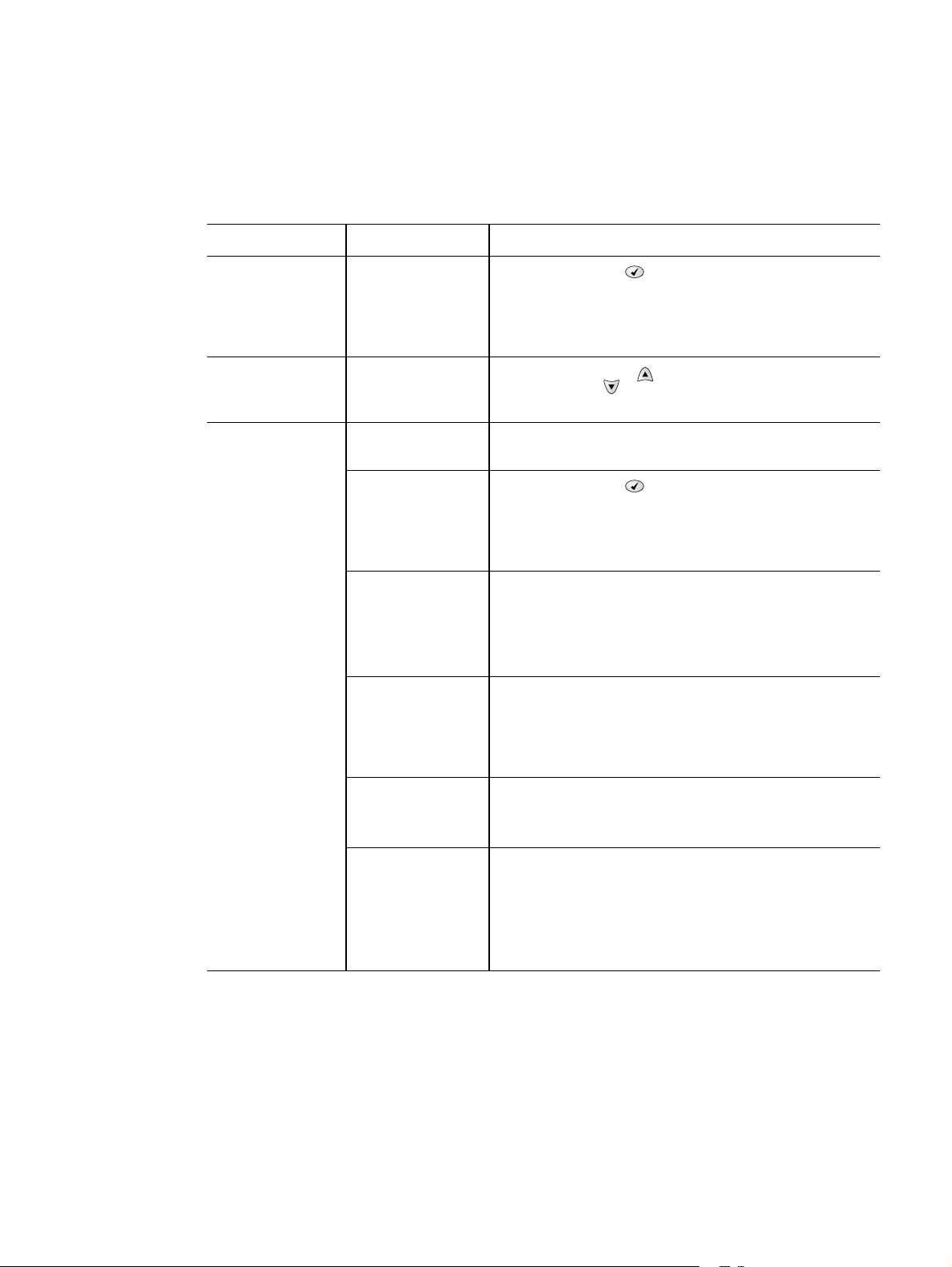
Engine test page
To verify that the printer engine (all printer components except the formatter, formatter DIMMs,
EIO products, and the stacker or stapler/stacker) is functioning, print an engine test page. Use a
small, non-metallic, pointed object to depress the test-page switch, which is located on the right
side of the printer (callout 1).
The test page should have a series of vertical lines. The test page will print from the last tray you
printed from. However, if the printer has been turned off and then back on since the most recent
print job, the page will print from tray 2. The printer will continuously print test pages as long as
the test-page switch is depressed. The printer will not print a test page if it is in PowerSave
mode.
Hint A damaged formatter might interfere with the engine test. If the engine test page does not print,
try removing the formatter and performing the engine test again. If the engine test is then
successful, the problem is almost certainly with the formatter, the control panel, or the cable that
connects them.
Figure 204. Engine test-page switch
Formatter test page
To verify that the formatter is functioning, print a configuration.
1. Press the S
2. Press the D
3. Press the S
ELECT ( ) button to open the MENUS.
OWN ARROW ( ) button to scroll to INFORMATION.
ELECT ( ) button to select INFORMATION.
11
4. Press the D
5. Press the S
254 Troubleshooting Q2431-90912
OWN ARROW ( ) button to scroll to PRINT CONFIGURATION.
ELECT ( ) button to select PRINT CONFIGURATION.
Page 29

Interface troubleshooting
Communications checks
Note Communication problems are normally the customer’s responsibility. Time spent attempting to
resolve these problems might not be covered by the Hewlett-Packard product warranty.
Refer the customer to the network administrator for assistance in troubleshooting network
problems.
If the printer is not connected directly to a Windows or MS-DOS-based host, see “EIO
troubleshooting” on page 255.
CAUTION HP LaserJet printers are not designed to work with mechanical switch-box products without
proper surge protection. These devices generate high transient voltages that cause permanent
damage to the formatter PCA. This circumstance is not covered by the Hewlett-Packard product
warranty.
Computer direct connect (parallel) test
After the printer is installed, verify communications by bypassing the Windows driver between
the printer and the IBM-compatible computer. Type the following at the MS-DOS prompt:
C:\DIR>LPT1 Enter (for printing to parallel port #1)
The printer should print a directory listing of the C: \ directory. You might need to press [G
the control panel to print the data in the buffer.
O] on
EIO troubleshooting
If the printer contains an optional HP Jetdirect print server, and you cannot communicate with the
printer over the network, verify that the print server is operating. Print a configuration page (see
“Configuration page” on page 241). If the Jetdirect card does not appear under “Installed
personalities and options” on the configuration page, reseat or replace the Jetdirect EIO card.
See the troubleshooting section of the HP Jetdirect Print Server Software Administrators Guide.
When the HP Jetdirect print server is installed correctly, print a Jetdirect page (this page
automatically prints when a Jetdirect print server is installed and a configuration page is printed).
See “Jetdirect page” on page 256. The Jetdirect page contains valuable network related
information about the printer.
If the host system and printer are still not communicating, replace the formatter PCA and the
EIO card and reconfigure the printer.
The following illustration shows the contents of the Jetdirect page.
Q2431-90912 Chapter 7 Troubleshooting 255
Page 30
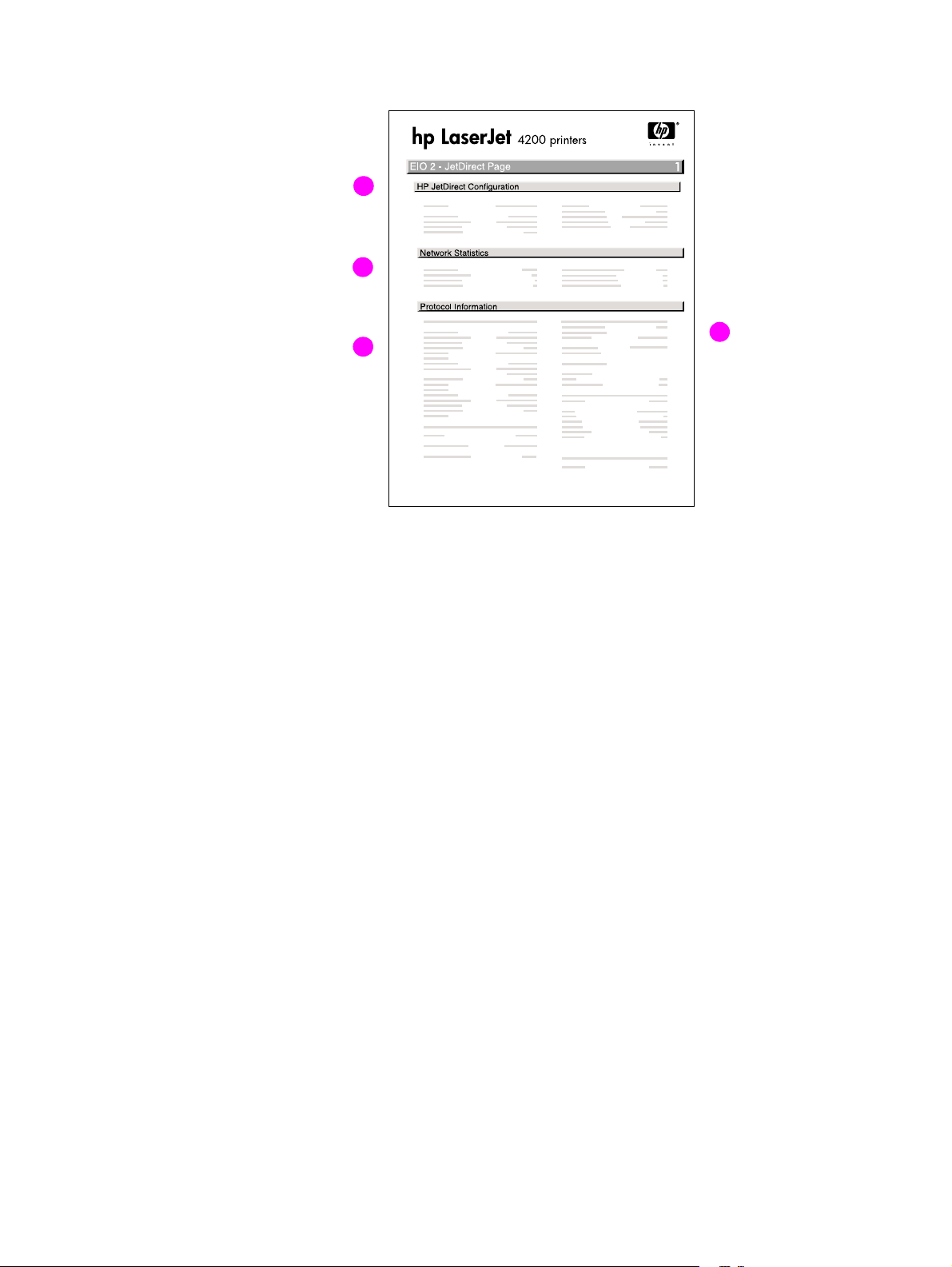
Jetdirect page
A
B
Figure 205. Jetdirect page
A. HP Jetdirect Configuration
B. Network Statistics This block indicates that network activity has been occurring. Bad
C
D
If the EIO Jetdirect card properly installed and th e printer c ompletes its
internal diagnostics, the I/O CARD READY status message prints. If
communication is lost, an I/O NOT READY status message prints,
followed by a two-digit error code. See the
HP Jetdirect Network Interface ConfigurationGuide for further details
and recommended action.
packets, framing errors, unsendable packets, and collisions should be
minimal. If a high percentage (greater than one percent) of these
occur, contact the network administrator. All of the statistics are set to
zero when the printer is turned off.
C. TCP/IP In this block, the default IP address is “192.0.0.192.” you can operate
the printer with this default address. The error message ARP
DUPLICATE ADDRESS might appear in this block. This is also an
acceptable error code if the TCP/IP protocol is not being used. Check
with the network administrator to determine the correct IP address for
the printer. To configure the printer’s IPaddress, go to the control
panel EIO menu, select CFG NETWORK=YES, select CFG TCP/IP=YES,
and then select BOOTP=NO.
D. Novell/NetWare This block should state the name of the Novell printer server to which
the printer is connected. If the node name reads“NPIxxxxxx” (where
xxxxxx = the last six digit s of the EIO’s LAN address), the EIO card has
not been configured for a Novell server. This could indicate that the
card is operating under protocol other than Novell. Check with the
network administrator to determine what node name might be
appropriate.
256 Troubleshooting Q2431-90912
Page 31

Display-message troubleshooting
The following tables explain the messages that might appear on the control-panel display or in
the event log. Alphabetical printer messages and their meanings are listed in “Alphabetical
printer messages” on page 258, and numerical printer messages are listed in “Numerical printer
messages” on page 274.
Note Not all messages are described in the tables; the messages that are not listed are self-explanatory.
Status messages
Status messages reflect the current state of the printer. They inform you of normal printer
operation and require no interaction to clear them. They change as the state of the printer
changes. Whenever the printer is ready, is not busy, and has no pending warning messages, the
status message READY
Warning messages
Warning messages inform you of data and print errors. These messages typically alternate with
READY
or with status messages and continue to appear until the SELECT ( ) bu tto n i s pr es se d. I f
CLEARABLE
when the next print job is sent to the printer.
WARNING is set to JOB in the printer’s configuration menu, these messages are cleared
appears if the printer is online.
Error messages
Error messages inform you that an action must be performed, such as adding paper or clearing a
paper jam.
Some error messages are auto-continuable (these are not critical errors and the printer will
continue to function). If the printer setting AUTO CONTINUE=ON is used, the error message will
continue to appear for about 10 seconds and then the printer will resume printing.
Note Pressing any button while an auto-continuable error message appears on the control-panel
display overrides the auto-continue feature, and the button’s function will take precedence. For
example, pressing the CANCEL JOB button will cancel the job.
Critical-error messages
Critical-error messages inform you of a device failure. Some of these messages can be cleared
by turning the printer off and then on. These messages are not affected by the auto-continue
setting. If a critical error persists, then service is required.
Q2431-90912 Chapter 7 Troubleshooting 257
Page 32

Alphabetical printer messages
Note Not all messages are described in the tables; the messages that are not listed are self-explanatory .
Table 41. Alphabetical printer messages
Message Description Action
ACCESS DENIED
MENUS LOCKED
BAD DUPLEXER CONNECTION The duplexer is not functioning. 1. Turn off the printer.
BAD ENVELOPE FEEDER CONNECTION The envelope feeder is not
An attempt has been made to
modify a printer menu item, but
the network systems
administrator has enabled the
control-panel security
mechanism. The message will
disappear shortly, and the printer
will return to the ready state.
functioning.
Contact the network systems
administrator to change settings.
2. Remove and then reinstall
the accessory.
3. Turn on the printer.
4. Check the rear accessory
power connector.
5. If the error persists, replace
the duplexer.
1. Turn off the printer .
2. Remove, and then reinstall
the accessory.
3. Turn on the printer.
4. Check the front accessory
power connector.
5. If the problem persists,
replace the envelope feeder.
CANNOT DUPLEX Check rear bin
or
CANNOT DUPLEX Check paper
CARTRIDGE FAILURE
For help press
alternates with
RETURN FOR REPLACEMENT
For help press
CHOSEN PERSONALITY NOT
AVAILABLE
For help press
alternates with
CHOSEN PERSONALITY NOT
AVAILABLE
To continue press
The printer cannot perform the
duplex function.
The print cartridge contains part
of the sealing tape.
The printer job language
(PJL) encountered a request for a
personality that did not e xist in the
printer. The job is aborted and no
pages print.
1. Close the face-up bin before
sending a duplex print job.
2. Replace the duplexer.
3. Replace the
DC controller PCA.
See “DC controller PCA” on
page 181.
1. Try to remove the sealing
tape.
2. If the sealing tape cannot be
removed, insert a new print
cartridge and return the faulty
print cartridge for
replacement.
1. Press the H
detailed information.
2. Press the U
button and the
D
OWN ARROW ( ) button to
step through the instructions.
ELP ( ) button for
P ARROW ()
258 Troubleshooting Q2431-90912
Page 33

Table 41. Alphabetical printer messages (continued)
Message Description Action
CLOSE TOP COVER
For help press
DATA RECEIVED
To print last page press
DETECTABLE SIZE
IN TRAY XX
For help press
alternates with
DETECTABLE SIZE IN TRAY XX
Recommend move
switch to STANDARD
DISK DEVICE
FAILURE
alternates with
READY
For menus press
The top cover is open or the top
cover s witc h (SW101) is defectiv e .
The printer received data and is
waiting for a form feed. When the
printer receives another file, the
message should disappear.
A tray has been loaded with
media that is a standard size and
the switch in the tray is set to
“custom.”
A device failure has occurred on
the specified drive.
1. Press the HELP ( ) button for
information.
2. Close the top cover.
3. Replace the top cover
switch (SW101). See figure
212 on page 335.
Press the S
ELECT ( ) button to
continue.
1. Press the HELP ( ) the for
detailed information.
2. Press the U
P ARROW ()
button and the
D
OWN ARROW ( ) button to
step through the instructions.
1. Printing can continue for jobs
that do not require access to
the disk drive.
2. Press the S
ELECT ( ) button
to continue.
3. If the message persists,
remove and reinstall the
EIO disk drive.
4. Reinitialize the EIO disk.
5. If the message persists,
replace the EIO disk drive.
DISK FILE
OPERATION FAILED
alternates with
READY
For menus press
DISK FILE
SYSTEM IS FULL
alternates with
READY
For menus press
DISK IS
WRITE PROTECTED
alternates with
READY
For menus press
The printer received a PJL file
system command that attempted
to perform an illogical operation
(for example, a command to
download a file to a nonexistent
directory).
The printer received a PJL file
system command that attempted
to store something on the file
system. The attempt was
unsuccessful because the file
system is full.
The file system device is
protected and no new files can be
written to it.
1. Printing can continue.
2. Press the S
ELECT ( ) button
to continue.
3. If the message reappears,
then a problem might exist
with the software application.
1. Use the device storage
manager in the HP Web
Jetadmin software to delete
files from the EIOdisk drive
and then try again.
2. Press the S
ELECT ( ) button
to continue.
1. To enable writing to the disk,
turn off the write protection by
using the device storage
manager in HP Web
Jetadmin.
2. Press the S
ELECT ( ) button
to continue.
Q2431-90912 Chapter 7 Troubleshooting 259
Page 34

Table 41. Alphabetical printer messages (continued)
Message Description Action
EIO DISK X
NOT FUNCTIONAL
For help press
The EIO disk in slot X is not
working correctly.
1. Remove the EIOdisk from
the indicated slot and reinstall
it.
2. If the error persists, replace
the EIO disk drive
ENVELOPE FEEDER EMPTY The envelope feeder is empty. 1. Refill the envelope feeder.
2. Turn off the printer.
3. Remove and then reinstall
the accessory. Turn the
printer on.
4. If the error persists, replace
the envelope feeder.
FLASH DEVICE
FAILURE
A flash DIMM is installed in one of
the formatter slots.
1. Printing can continue for jobs
that do not require the
flash DIMM.
alternates with
2. Press the S
ELECT ( ) button
to continue.
READY
For menus press
3. If the message persists,
remove and reinstall the
flash DIMM. See “Firmware
DIMM” on page 160.
4. If the message persists,
replace the flash DIMM. See
“Firmware DIMM” on
page 160.
FLASH FILE
OPERATION FAILED
The printer received a PJL file
system command that attempted
to perform an illogical operation
alternates with
(for example, a command to
download a file to a non-existent
READY
directory).
For menus press
FLASH FILE
SYSTEM IS FULL
The printer received a PJL file
system command that attempted
to store something on the file
alternates with
system. The attempt was
unsuccessful because the file
READY
system is full.
For menus press
FLASH IS
WRITE PROTECTED
The file system de vi ce is
protected and no ne w files can be
written to it.
alternates with
READY
For menus press
INCORRECT The wrong personal identification
number (PIN) was typed.
1. Printing can continue.
2. Turn the printer off and then
back on to delete the
message from the display.
3. If the message reappears, a
problem might exist with the
software applicati on.
1. Use HP Web Jetadmin
Device Storage Manager
software to delete files from
the flash memory and try
again.
2. Press the S
ELECT ( ) button
to continue.
1. To enable writing to the flash
memory, turn off the write
protection by us ing the device
storage manager in HP Web
Jetadmin.
2. Press the S
ELECT ( ) button
to continue.
Type the correct PIN code. After
three incorrect PIN entries, the
printer returns to the Ready state.
260 Troubleshooting Q2431-90912
Page 35

Table 41. Alphabetical printer messages (continued)
Message Description Action
INSERT OR CLOSE
TRAY XX
For help press
Tray XX must be inserted or
closed before the current job can
be printed.
1. Press the HELP ( ) button
for detailed information.
2. Press the U
P ARROW ()
button and the
D
OWN ARROW ( ) button to
step through the instructions.
3. If the error persists, verify th at
the indicated tray’s
media-size sensor(PS102,
SW801, or SW1) is properly
operating. See figure 213 on
page 336, figure 21 7 on page
340, or figure 220 on page
343. Verify that the sensor
“fingers” inside the tray are
engaging the tray sensor
correctly.
4. Print a configuration page.
See “Configurati on pag e” on
page 241.
5. If the tray settings on the
configuration page are
correct, verify that the tra y ’s
paper-out sensor is
operating. See “Printer
switches and se nsors” on
page 336, “500-sheet feeder
switches , sens ors , soleno ids,
and PCAs” on page 340, or
“1,500-sheet f eeder s witches,
sensors, solenoids,
and PCAs” on page 343.
INSTALL CARTRIDGE
alternates with
For help press
The cartridge is either not
installed or not correctly installed
in the printer.
1. Insert the cartridge, or make
sure that the cartridge is fully
seated.
2. Press the H
ELP ( ) button
for detailed information.
3. Press the U
P ARROW ()
button and the
D
OWN ARROW ( ) button to
step through the instructions.
4. If the error persists, replace
the cartridge.
5. Verify that the connectors
between power supply and
transfer assembly are not
damaged.
6. Replace the power supply.
See “Power supply” on
page 188.
7. Replace the transfer
assembly. See “Transfer
assembly” on page 200.
Q2431-90912 Chapter 7 Troubleshooting 261
Page 36

Table 41. Alphabetical printer messages (continued)
Message Description Action
INSTALL FUSER
For help press
The fuser is either not installed or
not correctly installed in the
printer.
1. The fuser is not fully seated
or has been removed and
must be reinstalled for
printing to continue. See
“Fuser” on page 162.
● If the fuser is in the printer,
remove and reinstall it.
● If the fuser is not in the printer,
install it.
2. Push the fuser firmly into the
printer until the b lue le vers on
both sides click into place.
3. Press the H
ELP ( ) button for
detailed information.
4. Press the U
P ARROW ()
button and the
OWN ARROW ( ) button to
D
step through the instructions.
5. If the error persists, verify t hat
the fuser connector
(J128 for the
HP LaserJet 4200; J228 for
the HP LaserJet 4300) is
good.
6. Replace the fuser assembly.
See “Fuser” on page162.
7. Replace the DC controller
PCA. See
“DC controller PCA” on
page 181.
8. Replace the power supply.
See “Power supply” on
page 188.
LOAD TRAY XX:
<TYPE> <SIZE>
For help press
alternates with
LOAD TRAY XX:
<TYPE> <SIZE>
TO USE ANOTHER
TRAY PRESS
Tray XX is either empty (based on
the operation of the paper sen sor)
or configured for a type and size
other than that specified in the
job.
1. Press the H
ELP ( ) button
for detailed information.
2. Press the U
P ARROW ()
button and the
D
OWN ARROW ( ) button to
step through the instructions.
3. Print a configuration page
and verify that the tray
settings are correctly set. See
“Configuration page” on
page 241.
4. If the tray settings on the
configuration page do not
match the actual tray setting,
verify that the indicate d tr ay’s
paper width switch (SW102,
SW801, or SW1) is operatin g
correctly. See figure 213 on
page 336, figure 2 17 on page
340, or figure 220 on page
343.
262 Troubleshooting Q2431-90912
Page 37

Table 41. Alphabetical printer messages (continued)
Message Description Action
LOAD TRAY XX:
<TYPE> <SIZE>
For help press
LOWER THE OPTIONAL BIN
Note:
The stacker or stapler/stacker LED
blinks in amber.
Tray XX is either empty (bas ed on
the operation o f the pa per sens or)
or configured for a type and size
other than that specified in the
job. No other tray is available.
The stacker or stapler/stacker
output bin is in the rai se d po si tion.
1. Press the HELP ( ) button
for detailed information.
2. Press the U
P ARROW ()
button and the
D
OWN ARROW ( ) button to
step through the instructions.
3. Print a configuration page
and verify that the tray
settings are correct ly set. See
“Configuration pag e” on
page 241.
4. If the tray settings on the
configuration page do not
match the actual tray setting,
verify that the indicated tray’s
paper width switch (PS106,
SW801, or SW1) is opera ting
correctly. See figure 213 on
page 336, figure 21 7 on page
340, or figure 220 on page
343.
1. Lower the output bin.
2. If this error persists, replace
the stacker or stapler/stacker.
MANUALLY FEED
<TYPE> <SIZE>
For help press
alternates with
MANUALLY FEED
<TYPE> <SIZE>
To continue press
A job was sent that requires a
specific paper type and size that
is not currently available.
1. Press the H
ELP ( ) button for
detailed information.
2. Press the U
P ARROW ()
button and the
D
OWN ARROW ( ) button to
step through the instructions.
3. If the requested paper size
and type is installed in o ne of
the trays , print a configuratio n
page (see “Configuration
page” on page 241) to see if
the printer tray setting differ
from the pa per size and type
in the tray.
4. Check the tray size sensor
switches if the configuration
page indicates a different
size than that in the tray.
Verify that the sensor
“fingers” inside the tray are
engaging the tray sensor
correctly. See “Tray 2, 500-,
1,500-sheet feeder media
size detection” on page 83.
Q2431-90912 Chapter 7 Troubleshooting 263
Page 38
Table 41. Alphabetical printer messages (continued)
Message Description Action
NON HP CARTRIDGE
DETECTED
The printer has detected that an
HP print cartridge is currently
installed.
If a new HP cartridge has been
installed, this message appears
for about 20seconds and then is
replaced by the READY message.
1. If the print cartridge appears
to be an authenticHP
cartridge, try installing
another HP print cartri dge
that has the same shipment
lot number. If this clears the
error message, return the
print cartridge that you
removed to the supplier as
defective.
2. If the error message persists,
the print cartridge might be a
fraudulent cartridge.
3. If the error message persists,
the memory chip on the print
cartridge (location J600)
might be defective o r the
connector might be defective.
4. The DC controller PCA might
be defective. Replace the
DC controller PCA. See
“DC controller PCA” on
page 181.
NOTE:
Printer repairs that are required
as a result of using non-HP print
cartridges are not covered under
the HP warranty.
NON HP CARTRIDGE
DETECTED
alternates with
READY
For menus press
The printer has detected that a
non-HP print cartridge is currently
installed.
1. If the print cartridge appears
to be an authenticHP
cartridge, try installing
another HP print cartri dge
that has the same shipment
lot number. If this clears the
error message, return the
print cartridge you removed
to the supplie r and report that
it is defective.
2. If the error message persists,
the print cartridge might be a
fraudulent cartridge.
3. If the error message persists,
the memory chip on the print
cartridge or the connector
(location J600) might be
defective.
4. The DC controller PCA might
be defective. Replace the
DC controller PCA. See
“DC controller PCA” on
page 181.
NOTE:
Printer repairs that are required
as a result of using non-HP print
cartridges are not covered under
the HP warranty.
264 Troubleshooting Q2431-90912
Page 39

Table 41. Alphabetical printer messages (continued)
Message Description Action
OUTPUT BIN 1 FULL
REMOVE ALL PAPER
FROM BIN
Note:
The stacker or stapler/stacker
LED blinks in amber.
OUTPUT PAPER PATH OPEN
Note:
The stacker or stapler/stacker LED
blinks in amber.
PERFORM PRINTER MAINTENANCE
alternates with
READY
For menus press
The stacker or stapler/stacker
output bin is full and must be
emptied in order to continue
printing.
The jam-access do or or the sta ple
cartridge door is open.
To ensure optimu m print quali ty,
the printer prompts y ou to perf orm
routine maintenance every
200,000 pages (default setting).
● Q2429A; 110 V printer kit
for the HP LaserJet 4200
● Q2436A; 110 V printer kit
for the HP LaserJet 4300
● Q2430A; 220 V printer kit
for the HP LaserJet 4200
● Q2437A; 220 V printer kit
for the HP LaserJet 4300
1. Remove the media from the
output bin.
2. If the error persists, verify th at
the output bin flapper (the
four plastic paddles hanging
down in fr ont of the outp ut bin
rollers) can move freely.
3. Replace the stacker or
stapler/stacker.
1. Press the H
ELP ( ) button
for detailed information.
2. Press the U
P ARROW ()
button and the
D
OWN ARROW ( ) button to
step through the instructions.
3. Close the open door.
4. If this message persists,
replace the stacker or stapler/
stacker.
Install an HP LaserJet 4200/4300
printer maintenance kit. See the
instructions that come with this kit.
-or-
Continue printing and order a
printer maintenance kit
For information about how to
order a maintenance kit, see
chapter 8 in this manual.
PERFORMING UPGRADE A firmware upgrade is in progress. CAUTION
Do not turn the printer off until the
printer returns to the Ready state .
The printer will be damaged if the
power is turned off during a
firmware upgrade.
PRINTING...
REGISTRATION PAGE
The printer is generating the
registrat ion page. The printer will
Follow the instructions on the
printed pages.
return to the Ready state when
the page is completed.
Q2431-90912 Chapter 7 Troubleshooting 265
Page 40

Table 41. Alphabetical printer messages (continued)
Message Description Action
RAM DISK DEVICE
FAILURE
alternates with
READY
For menus press
RAM DISK FILE
OPERATION FAILED
alternates with
READY
For menus press
RAM DISK FILE
SYSTEM IS FULL
alternates with
READY
For menus press
The RAM disk ha d a critical f ailur e
and can no longer be used.
The printer received a PJL file
system command that attempted
to perform an illogical operation
(for example, a command to
download a file to a nonexistent
directory).
The RAM disk is full. 1. Delete files and then try
1. Turn the printer power off,
and then on again.
2. If this error persists, a
defective DRAM DIMM might
be installed in the printer (on
the formatter). Replace the
DRAM DIMM(s). The
procedure for replacing a
DRAM DIMM is the same as
replacing a firmware DIMM.
See “Firmware DIMM” on
page 160.
1. Printing can continue.
2. Turn the printer off and then
on to delete the message
from the display.
3. If this error persists, a
problem might exist with the
software applicati on.
again, or turn the printer off
and then on to delete all the
files on the RAM disk.
2. If the message persists,
increase the size of the
RAM disk by adding
additional memory DIMMs.
RAM DISK IS
WRITE PROTECTED
alternates with
READY
For menus press
RECEIVING
UPGRADE
REINSERT DUPLEXER The duplexer is not functioning. 1. Tu rn off the printer.
The file system de vi ce is
protected and no ne w files can be
written to it.
A firmware upgrade i s in p rogre ss . CAUTION
T o enable w riting to the RA M disk,
turn off the write protection by
using the dev ice storag e manager
in the HP Web Jetadmin software.
Do not turn the printer off until the
printer returns to the ready state.
The printer will be damaged if the
power is turned off during a
firmware upgrade.
2. Remove and then reinstall
the accessory.
3. Turn on the printer.
4. Check the rear accessory
power connector.
5. If the error persists, replace
the duplexer.
266 Troubleshooting Q2431-90912
Page 41

Table 41. Alphabetical printer messages (continued)
Message Description Action
REPLACE
CARTRIDGE
alternates with
For help press
RESEND
UPGRADE
No toner remains in the print
cartridge. Printing can continue
until the toner supply is depleted.
The fir mware upgrade was not
completed success fu lly.
1. Replace the print cartridge to
continue printing.
1. Press the H
ELP ( ) button for
detailed information.
2. Press the U
P ARROW ()
button and the
OWN ARROW ( ) button to
D
step through the instructions.
3. Supplies-ordering inf ormation
is also available from the
embedded Web server.
4. If this error persists, replace
the power supply. See
“Power supply” on page 188.
Attempt the upgrade again.
Q2431-90912 Chapter 7 Troubleshooting 267
Page 42

Table 41. Alphabetical printer messages (continued)
Message Description Action
SIZE MISMATCH
TRAY XX=<SIZE>
For help press
alternates with
READY
For menus press
The tray is lo aded with m edia that
is longer or shorter in the feed
direction than the size setting for
the tray.
1. Adjust the side and rear
paper guides against the
paper. From the control
panel, set the tray 1 paper
size to the medi a size t hat will
be used in tray 1.
2. If the media being used is
Letter, A4, Executive, B5 JIS,
A5, or Legal size, the tray
switch should be set to
“standard.” Set the tr ay switc h
to “custom” for all other
media sizes. The custom size
switch mu st be set be f or e the
size can be sele cted at the
control panel.
3. Print a configuration page
and verify that the tray size
settings match the actual tray
settings. If the settin gs do not
match, verify that the tra y size
sensors are correctly
functioning. If they are not,
replace the media-size
sensors (SW102, SW801, or
SW1). See figure 213 on
page 336, figure 2 17 on page
340, or figure 220 on page
343. Verify that the sensor
“fingers” inside the tray are
engaging the tray sensor
correctly. See “Tray 2, 50 0-,
1,500-sheet feeder media
size detection” on page83.
4. Replace the indicated feeder
control PCA. For the
500-sheet feeder, see
“500-sheet feeder
control PCA” on page 207.
For the 1,500-sheet feeder,
see “1,500-sheet feeder
control PCA” on page 220.
5. Replace the
DC controller PCA. See
“DC controller PCA” on
page 181.
STANDARD OUTPUT BIN FULL
Remove all paper from bin
The top (standard) output bin is
full and must be emptied.
1. Empty the top output bin.
2. If the error persists, verify t hat
the output bin
sensor (PS104) is operating
and that the sensor arm can
freely move. See figu re 213
on page 336.
268 Troubleshooting Q2431-90912
Page 43

Table 41. Alphabetical printer messages (continued)
Message Description Action
STAPLER LOW ON STAPLES
For help press
Note:
The stapler/stacker LED is
continuously illuminate d green (t his
error applies to the stapler/stacker
only).
STAPLER OUT OF STAPLES
For help press
Note:
The stapler/stacker LED blinks in
amber (this error applies to the
stapler/stacker only).
Fewer than 70 staples remain in
the optional stapler/stacker staple
cart ridge. Printing will continue
until the STAPLER OUT OF STAPLES
message appears on the printer
control-panel display.
Fewer than 15 staples remain in
the optional stapler/stacker. The
printer behavior depends on how
STAPLES OUT is configured.
● If STAPLES OUT=STOP, the
printer stops printing until you
refill the stapler or press the
ELECT ( ) button. This is the
S
default setting.
● If STAPLES OUT=CONTINUE,
printing continues but following
jobs will not be stapled.
1. Press the HELP ( ) button
for detailed information.
2. Press the U
P ARROW ()
button and the
D
OWN ARROW ( ) button to
step through the instructions.
3. If after following the
instruction above this error
persists, replace the staple
unit. See “To remove and
replace the stapler unit” on
page 60.
NOTE:
The customer is responsible for
ordering replacement staple
cartridges.
1. Press the H
ELP ( ) button
for detailed information.
2. Press the U
P ARROW ()
button and the
OWN ARROW ( ) button to
D
step through the instructions.
3. Replace the staple cartridge.
4. If this error persists, Replace
the stapler unit (see “To
remove and replace the
stapler unit” on page60)
follow ed by the
stapler/stacker if necessary.
TOO MANY PAGES IN JOB TO
STAPLE
Note:
The stapler/stacker LED is
continuously illuminated in green
(this error applies to the stapler/
stacker only)
TOO MANY TRAYS INSTALLED
Turn power off and unistall a
tray.
The maximum number of sheets
the stapler can staple is 15. The
print job finishes printing b ut is not
stapled.
Too many optional input trays are
installed. A maximum of two
optional trays is allowed.
Reduce the number of pages in
the print job, or print and sta ple in
batches of 15 or fewer pages.
Turn off the printer power and
remove a tray.
Q2431-90912 Chapter 7 Troubleshooting 269
Page 44

Table 41. Alphabetical printer messages (continued)
Message Description Action
TRAY XX CONTAINS
UNKNOWN MEDIA
TRAY XX EMPTY
<TYPE> <SIZE>
alternates with
READY
For help press
The media type or size in the
specified tray cannot be
determined.
The specified tray is empty, but
the current job does not require
this tray in order to print correctly.
1. To change the media type ,
press the S
ELECT ()
button. Use the
P ARROW ( ) button and
U
the D
OWN ARROW ()
button to scroll to the type,
and then press the
ELECT ( ) button to select
S
it.
2. To change the media size to
Letter, A4, Executive, B5 JIS,
A5, or Legal, leave the tray
switch in the “standard”
position.
3. To change the media size to
other sizes, move the tray
switch to “custom”, adjust the
paper guides against the
paper, and close the tra y. Use
P ARROW ( ) button
the U
and the D
OWN ARROW ()
button to scroll to the media
size, and then press the
ELECT ( ) button to select
S
it.
1. Refill the indicated tray.
2. If the error persists, verify t hat
the indicated tray’s paper-out
sensor (PS105,PS101,
PS801, or SR3) is properly
functioning correctly. See
figure 213 on page 336,
figure 217 on page 340, or
figure 220 on page 343.
TRAY XX OPEN
For help press
The specified tray is open or not
closed completely.
1. Close the tray.
2. If this error persists, verify
that the indicated tray’s
alternates with
media-size sensors (SW102,
SW801, or SW1) is properly
READY
For menus press
functioning correctly. See
figure 213 on page 336,
figure 217 on page 340, or
figure 220 on page 343.
Verify that the sensor
“fingers” inside the tray are
engaging the tray sensor
correctly. See “Tray 2, 50 0-,
1,500-sheet feeder media
size detection” on page83.
270 Troubleshooting Q2431-90912
Page 45

Table 41. Alphabetical printer messages (continued)
Message Description Action
TRAY XX SIZE=
<XXXX SIZE>
For help press
A tray was installed with the
standard/custom switch set to
“custom”, or with th e paper guid es
in a non-standard configuration.
The printer is prompting you to
use the control panel to specify a
predefined non-standard paper
size, a ”custom” paper size, or an
“any custom” or an “any” siz e
setting. (The user’s software
program define s the “any custom”
and “any” size settings.)
1. Use the control panel to
select the appropriate c ustom
paper size. Press the
ELECT () button.
S
2. If the media used is Letter,
A4, Executive, B5 JIS, A5, or
Legal sized, the tray switch
should be set to “standard.”
Set the tray switch to
”custom” for all other media
sizes. The tray switch must
be set to custom before the
size can be selected at the
control panel.
3. Print a configuration page
and verify that the tray size
settings match the actual tra y
settings. If the settings do not
match, verify that t he tra y size
sensors are properly
functioning. If they are not,
replace the media-size
sensors (SW102, SW801, or
SW1). See figure 213 on
page 336, figure 21 7 on page
340, or figure 220 on page
343. Verify that the sensor
“fingers” inside the tray are
engaging the tray sensor
correctly. See “Tray 2, 500-,
1,500-sheet feeder media
size detection” on page 83.
Q2431-90912 Chapter 7 Troubleshooting 271
Page 46

Table 41. Alphabetical printer messages (continued)
Message Description Action
TRAY XX
<TYPE> <SIZE>
TO CHANGE TYPE
PRESS
alternates with
TRAY XX
<TYPE> <SIZE>
SIZE DETECTED BY TRAY
The printer is reporting the current
configuration of tray XX. The tray
switch is in the “standard”
position.
1. To change the media type ,
press the S
ELECT ()
button. Use the
P ARROW ( ) button and
U
the D
OWN ARROW ()
button to scroll to the type,
and then press the
ELECT ( ) button to select
S
it.
2. To change the media size to
Letter, A4, Executive, B5 JIS,
A5, or Legal, leave the tray
switch in the “standard”
position and adjust th e media
guides to the correct
positions.
3. To change the media size to
other sizes, move the tray
switch to “custom”, adjust the
paper guides against the
paper, and close the tray.
4. Use the U
P ARROW ()
button and the
D
OWN ARROW ( ) button to
scroll to the media size, and
then press the S
ELECT ()
button to se lect it. Repea t this
procedure to selec t the media
type.
5. If the size that appears o n the
control panel display is
incorrect and the tray paper
guides are properly adju sted,
verify that the indicate d tr ay’s
media-size sensor (SW102,
SW801, or SW1) is
operating. See figure 213 on
page 336, figure 2 17 on page
340, or figure 220 on page
343. Verify that the sensor
“fingers” inside the tray are
engaging the tray sensor
correctly. See “Tray 2, 50 0-,
1,500-sheet feeder media
size detection” on page83.
272 Troubleshooting Q2431-90912
Page 47

Table 41. Alphabetical printer messages (continued)
Message Description Action
TRAY XX
<TYPE> <SIZE>
SIZE SPECIFIED BY USER
alternates with
TRAY XX
<TYPE> <SIZE>
TO CHANGE TYPE
PRESS
UNABLE TO STORE JOB
<JOBNAME>
The printer is reporting the current
configuration of tray XX. The tray
switch is in the “custom” position.
A job cannot be s tored becau se of
a memory, disk, or configuration
problem.
1. To change the media type,
press the S
ELECT ()
button. Use the
P ARROW ( ) button and
U
the D
OWN ARROW ()
button to scroll to the type,
and then press the
ELECT button to select it.
S
2. To change the media size to
Letter, A4 , Executive, B5 JIS,
A5, or Legal, set the tray
switch to the “standard”
position and adjus t the media
guides to the correct
positions.
3. To change the media size to
other sizes, leave the tra y
switch in the “custom”
position, adjust the media
guides against the media,
and close the tray.
4. Select the Paper Handling
menu from the control panel.
Configure the size and media
type for the tray.
1. Install additional memory in
the printer, or install a disk
drive in the printer . See
“Firmware DIMM” on
page 160.
2. If a disk drive is installed,
delete the previously stored
print jobs to increase th e disk
storage space.
3. If this error persists, check
the printer driver and
application program settings.
USE INSTEAD?
TRAY X: <TYPE>
<SIZE>
The printer is offering the closest
selection of alternative media to
use for the print job.
To choose the alternative, press
ELECT ( ) button. Use the
the S
P ARROW ( ) button and
U
OWN ARROW ( ) button to
the D
scroll to any alternative selection,
and then press the S
ELECT ()
button to select it.
Q2431-90912 Chapter 7 Troubleshooting 273
Page 48

Numerical printer messages
Table 42. Numerical printer messages
Message Description Action
10.00.00
SUPPLIES MEMORY ERROR
or
10.10.00
SUPPLIES MEMORY ERROR
For help press
13.XX.YY
DUPLEX JOB INTERRUPTED
For help press
alternates with
13.XX.YY
DUPLEX JOB INTERRUPTED
DISCARD TOP SHEET AND PRESS
or
13.XX.YY
DUPLEX JOB INTERRUPTED
DISCARD TOP TWO SHEETS AND
PRESS
The printer is unable to read the
electronic information (e-label) on
the print cartridge so that the
printer can keep tr a ck of the page
count for the print cartridge.
XX Description
00 memory error on the cartridge
10 memory device not found
YY Description
00 black print cartridge
A duplex job was physically
interrupted as the paper was
momentarily routed to the output
bin during duplexing.
This error is usually caused by a
user attempting to g ra sp the edge
of the page as it exists the top
output bin during the duplexing
process.
1. Open the top cover, remove
the print cartridge, and
reinstall it. See “Print
cartridge” on page 137.
2. Install a new HP print
cartridge.
3. Check the connection
between the
DC controller PCA
(location J97) and the
memory chip on the print
cartridge (location J600).
4. Replace the memory chip
cable and contact assembly.
5. Replace the
DC controller PCA. See
“DC controller PCA” on
page 181.
1. Press the H
for more information.
2. Remove the specified
number of pages from the
output bin.
3. Press the S
to continue printing.
4. Replace the duplexer.
5. Replace the DC controller
PCA. See
“DC controller PCA” on
page 181.
NOTE: IF JAM RECOVERY = OFF
some pages will not be reprinte d.
Resend the missing pages.
ELP ( ) button
ELECT ( ) button
274 Troubleshooting Q2431-90912
Page 49
Table 42. Numerical printer messages (continued)
Message Description Action
13.XX.YY
JAM
For help press
A jam exists in the media path. 1. Press the HELP ( ) button for
detailed information about
clearing the jam.
2. Press the U
P ARROW ()
button and the
D
OWN ARROW ( ) button to
step through the instructions.
3. If the media is folding into an
accordion shape , make sure
the shutter on the print
cartridge opens as y ou i ns ert
the cartridge. Replace any
defective print cartridge.
4. For information about how to
resolve a jam, see the
specific numerical error
codes in this table (the
following 13.XX.YYerror
codes are not in numeric al
sequence).
5. See “Paper-path
troubleshooting” on page 295
in this chapter.
Q2431-90912 Chapter 7 Troubleshooting 275
Page 50

Table 42. Numerical printer messages (continued)
Message Description Action
13.01.00. or 13.03.00
JAM IN TRAY X
For help press
or
13.03.00
PAPER JAM OPEN INPUT TRAYS
THEN OPEN AND CLOSE TOP COVER
A page is jammed in tray X.
A 13.01.00 error message
indicates that the media did not
arrive at the pre-feed
sensor (PS102) within the
specified time.
A 13.03.00 error message
indicates that the media did not
arrive at the top-of-page
sensor (PS103) within the
specified time.
NOTE:
The 13.01.00 error can also be
caused by the failure of the
paper-level sensor (PS107). If this
sensor fails, the lifter motor does
not rotate to lift the paper tray
plate.
This error can also be caused
when the printer attempts to
pickup media from a tray that is
empty, but the paper-out sens in g
mechanism fo r that tra y h as failed
and the printer senses that the
tray appear to be loaded.
1. Press the H
ELP ( ) button
for detailed inf ormation about
clearing the jam.
2. Press the U
P ARROW ()
button and the
D
OWN ARROW ( ) button to
step through the instructions.
3. Check that the paper-out
sensor in the specified tr ay is
functioning properly.
4. Clean the pickup roller. If it is
worn or damaged, replace it.
5. Clean the feed and
separation rollers. If they are
worn or damaged, replace
them (always replace both
rollers at the same time).
6. Verify that the pre-feed
sensor (PS102) is installed
correctly. See “Correctly
install the paper-feed
assembly sensor flag” on
page 197.
7. Open and close the specified
tray while watching the
control-panel displ ay. A short
delay should occur between
when the tray closes and the
tray-size message appears
on the control-panel display.
If there is no delay and you
do not hear the tray-lift motor
lift the tray plate into place,
replace the tray’s stack
position sensor
(PS107, PS802, or SR2).
See “Printer switches and
sensors” on page 336,
“500-sheet feeder switches,
sensors, solenoids,
and PCAs” on page 340, or
“1,500-sheet f eeder s witches,
sensors, solenoids,
and PCAs” on page 343.
8. Replace the tray X pickup
solenoid.
9. Replace the tray 1
paper-pickup assembly. See
“Tray 1 paper-pickup
assembly” on page 192.
10. Replace the paper-feed
assembly. See “Paper feed
assembly” on page 195.
276 Troubleshooting Q2431-90912
Page 51

Table 42. Numerical printer messages (continued)
Message Description Action
CONTINUED
13.01.00. or 13.03.00
JAM IN TRAY X
For help press
or
13.03.00
PAPER JAM OPEN INPUT TRAYS
THEN OPEN AND CLOSE TOP COVER
13.02.00 or 13.05.00 or
13.20.00 or 13.21.00
JAM IN TOP
COVER AREA
For help press
CONTINUED CONTINUED
11. Verify that the top-of-page
sensor (PS103) is operating
correctly and that the sensor
flag can freely move. Repla ce
the sensor if it is not oper ating
correctly. See “Printer
switches and sensors” on
page 336.
12. Replace the
DC controller PCA. See
“DC controller PCA” on
page 181.
A jam exists in the top-cover area.
1. Press the H
for detailed i nf ormation a bout
A 13.02.00 error message
indicates that the media did not
pass the top-of-page
sensor (PS103) within the
specified time.
clearing the jam.
2. Press the U
button and the
D
OWN ARROW ( ) button to
step through the instructions.
3. Check the pre-feed,
A 13.05.00 error message
indicates that the media did not
arrive at the fuser delivery
sensor (PS108) within the
specified time.
top-of-page, and fuser
assembly sensors (PS102,
PS103 and PS 108) and
verify that the sensor arms
move freely. (sSe “Location
of printer switches and
A 13.20.00 error message
indicates that the printer power
was turned on or that the printer
attempted to initialize while the
pre-feed sensor (PS102), the top
of page sensor (PS102) and/or
the fuser delivery sensor (PS108)
was detecting media.
sensors” on page336.)
4. If the paper-feed assembly
has been replaced, v erify that
the pre-feed sensor (PS102)
is installed correctly. See
“Correctly install the
paper-feed assembly sensor
flag” on page 197.
5. Replace the top-of-page
A 13.21.00 error message
indicates that the top cover open
switch (SW101) was activated
while a print job was printing (the
top cover was opened or the
switch is defective).
sensor (PS103). See
“Location of printer switches
and sensors” on page336.
6. Replace the top-cover-o pen
switch (SW101). See
“Location of printer switches
and sensors” on page336.
7. Replace the fuser (PS108).
See “Fuser” on page 162.
8. Replace the
DC controller PCA. See
“DC controller PCA” on
page 181.
9. If this error message ap pears
frequently, see “Paper-path
troubleshooting” on
page 295.
ELP ( ) button
P ARROW ()
Q2431-90912 Chapter 7 Troubleshooting 277
Page 52

Table 42. Numerical printer messages (continued)
Message Description Action
13.06.00 and 13.12.00
JAM INSIDE REAR DOOR
For help press
A page is jammed near the rear
output door.
1. Press the HELP ( ) button for
detailed information about
clearing the jam.
2. Press the U
P ARROW ()
button and the
D
OWN ARROW ( ) button to
step through the instructions.
3. Check the paper width and
fuser delivery sensors
(PS106, PS108) and verify
that the sensor arms move
freely. (See “Location of
printer switches and sensors”
on page 336.)
4. Check the inside of the
duplexer for scraps of media
that might hav e torn off when
a jam was cleared.
5. Replace the media-size
sensor (PS106) and fuser.
See “Location of printer
switches and sens ors ” on
page 336 and “Fuser” on
page 162.
6. Turn the power off. Remove
the duplexer and turn the
power on. If the error
message persists, repla ce
the DC controller PCA. See
“DC controller PCA” on
page 181.
7. Replace the fuser (PS108).
See “Fuser” on page162.
8. If the error message appears
frequently, see “Paper-path
troubleshooting” on
page 295.
278 Troubleshooting Q2431-90912
Page 53

Table 42. Numerical printer messages (continued)
Message Description Action
13.12.07
JAM IN STAPLER
Note:
The stapler/stacker LED blinks in
amber (this error applies to the
stapler/stacker only).
13.12.08
JAM IN OUTPUT DEVICE
Note:
The stapler/stacker LED blinks in
amber (this error applies to the
stapler/stacker only).
There is a jam in the stapler
cartridge (the stapler did not f inish
stapling but its motor w as able to
return to its home position).
The output bin page-detection
sensor has been active for longer
than the specified time.
1. Press the H
ELP ( ) button
for detailed information.
2. Press the U
P ARROW ()
button and the
D
OWN ARROW ( ) button to
step through the instructions.
3. Remove any jammed paper
from the stapler/stacker.
4. Remove the staple cartridge
from the stapler unit.
5. Push the green door on the
end of the staple cartridge up
(in the direction of the
arrows).
6. Remove the jammed staple.
7. Close the staple cartridge
door. R eplace the cartridge in
the stapler unit.
8. Close the staple unit.
9. If the error persists, replace
the staple cartridge.
10. If the error persists, replace
the stapler unit. See
“Removing and replacing the
stapler unit” on page60.
1. Press the H
ELP ( ) button
for detailed information.
2. Press the U
P ARROW ()
button and the
OWN ARROW ( ) button to
D
step through the instructions.
3. Remove al l of the pages from
the output bin.
4. Open the jam-access door
and remove all of the pages.
Close the a c cess door.
5. If this error message persists ,
replace the stapler/stacker.
13.12.09
JAM IN OUTPUT DEVICE
For help press
The stacker or staple/stacker
inlet sensor has been active for
longer than a specified time.
1. Press the H
ELP ( ) button
for detailed information.
2. Press the U
P ARROW ()
button and the
D
Note:
The stacker or stapler/stacker LED
blinks in amber.
OWN ARROW ( ) button to
step through the instructions
3. Open the jam-access door
and remove all of the pages.
Close the a c cess door.
4. If this error message persists ,
replace the stacker or
stapler/stacker.
Q2431-90912 Chapter 7 Troubleshooting 279
Page 54

Table 42. Numerical printer messages (continued)
Message Description Action
13.12.10
JAM IN OUTPUT DEVICE
For help press
The event log records this error
message as 13.12.0A
Note:
The stacker or stapler/stacker LED
blinks in amber.
13.12.11
JAM IN OUTPUT DEVICE
For help press
The event log records this error
message as 13.12.0B
Note:
The stacker or stapler/stacker LED
blinks in amber.
A page did not arrive at the
stacker or staple/stacker
inlet sensor in the specified time.
A jam was detected when the
stacker or stapler/stacker power
was turned on.
1. Press the HELP ( ) button
for detailed information.
2. Press the U
P ARROW ()
button and the
D
OWN ARROW ( ) button to
step through the instructions
3. Open the jam-access door
and remove all of the pages.
Close the access door.
4. Verify that the output bin
deflector (in the printer) is
operating correctly.
5. If this error message persists,
replace the stacker or stapler/
stacker.
1. Press the H
ELP ( ) button
for detailed information.
2. Press the U
P ARROW ()
button and the
D
OWN ARROW ( ) button to
step through the instructions.
3. Remove all of the p ages f rom
the output bin.
4. Open the jam-access door
and remove all of the pages.
Close the access door.
5. If this error persists, replace
the stacker or the
stapler/stacker.
13.13.00
JAM INSIDE DUPLEXER
For help press
13.1C.00
FUSER JAM
For help press
A page is jammed inside of the
duplexer.
A jam exists in the fus er area. The
media is probably wrapped
around the fuser roller.
1. Press the H
ELP ( ) button for
detailed information about
clearing the jam.
2. Press the U
P ARROW ()
button and the
OWN ARROW ( ) button to
D
step through the instructions.
3. Check the inside of the
duplexer for scraps of media
that might have been torn off
when a jam was cleared.
4. Turn the power off. Remove
the duplexer and turn the
power on. If this error
persists, replace the
DC controller PCA. See
“DC controller PCA” on
page 181.
5. Replace the duplexer.
1. Remove the fus er.
2. Turn the b lu e k nob to rem o ve
the jammed media.
3. If necessary, replace the
fuser. See “Fuser” on
page 162.
280 Troubleshooting Q2431-90912
Page 55

Table 42. Numerical printer messages (continued)
Message Description Action
13.98.00
OPEN INPUT TRAYS THEN OPEN AND
CLOSE TOP COVER
20
INSUFFICIENT MEMORY
For help press
alternates with
20
INSUFFICIENT MEMORY
To continue press
● The face-up tray was opened
when the printer was attempting
to send a page to the duplexer.
● A page shorter than 200 mm
(7.87 inches) was sent to the
duplexer.
● A page less than 120 mm
(4.72 inches) in width was sent to
the duplexer.
● A multi-feed paper jam has
occurred.
The printer has received more
data from the compu ter than fits in
the ava ilable memory.
1. Remove any jammed media
from the paper path.
2. Open and close the top
cover.
3. Disconnect all optional
paper-handling acces s ories .
4. Replace the feed and
separation rollers. See
“Tray 2 feed rollers” on
page 141 (this procedure
includes the separation
roller).
5. Replace the
DC controller PCA. See
“DC controller PCA” on
page 181
1. Press the S
ELECT ( ) button
to resume printing.
Note: A loss of data will occur.
2. Reduce the comple xi ty of the
print job to avoid this error.
3. You might be able to print
pages that are more co mplex
if you add memory to the
printer.
21
PAGE TOO COMPLEX
For help press
alternates with
21
PAGE TOO COMPLEX
To continue press
22
EIO X BUFFER OVERFLOW
To continue press
22
PARALLEL I/O BUFFER OVERFLOW
For help press
alternates with
22
PARALLEL I/O BUFFER OVERFLOW
To continue press
The printer cannot process the
page quickly enough.
The printer’s EIO card in slot X
has overflowed its I/O buffer
during a busy state.
The printer’s parallel buffer has
overflowed during a busy state.
1. Press the S
ELECT ( ) button
to process the page.
Note: A loss of data will occur.
2. Make the page contents less
complex and re-send the
print job.
1. Press the S
ELECT ( ) button
to resume printing.
Note: A loss of data will occur.
2. Check the configuration of
the EIO card and the host
computer.
3. If this error message persists ,
replace the EIO card.
1. Press the S
ELECT ( ) button
to resume printing.
Note: A loss of data will occur.
2. Check the parallel I/O
configuration. Set
SPEED
to NO and ADVANCED
FUNCTIONS
3. Replace the formatter PCA.
See “Fo rmatter asse mb ly” on
page 161.
HIGH
to OFF.
Q2431-90912 Chapter 7 Troubleshooting 281
Page 56

Table 42. Numerical printer messages (continued)
Message Description Action
40
EIO X BAD TRANSMISSION
To continue press
41.3
UNEXPECTED SIZE IN TRAY XX
For help press
alternates with
41.3
LOAD TRAY XX: [TYPE] [SIZE]
For help press
A connection with the card in
EIO slot X has been broken
abnormally.
The media that is l oaded is longe r
or shorter in the feed direction
than the size that is co nfigure d for
the tray.
1. Press the SELECT ( ) button
to resume printing.
Note: A loss of data will occur.
2. Check that all of the cables
are connected to the
EIO ports and that the
EIO board is se ated pro perly.
3. If possible, print to another
network printer to verify the
network is working properly.
4. Check the configuration of
the EIO card.
5. If this error message persists,
replace the EIO card.
1. If the incorrect size was
selected, cancel the job or
press the H
gain access to help.
2. Press the U
button and the
OWN ARROW ( ) button to
D
step through the instructions.
3. Print a configuration page
and verify that the tray
settings match the media in
the tray. See “Configuration
page” on page 241.
4. Verify that the pre-feed,
top-of-page, and fuser
delivery- sensors
(PS102, PS103, PS108) are
operating and the sensor
flags can move freely. See
“Location of printer switch es
and sensors ” on page 336.
5. Replace the
DC controller PCA. See
“DC controller PCA” on
page 181.
ELP ( ) button to
P ARROW ()
41.X
PRINTER ERROR
For help press
alternates with
41.X
PRINTER ERROR
To continue press
A printer error has occurred.
1. Press the S
to continue or press the
S
X Description
1 unknown misprint error
2 beam-detect misprint error
4 no VSYNC error
7 feed-delay error
9 signal-noise error
H
ELP ( ) button for more
information.
2. If the message persists, turn
the printer power off and then
on again.
3. If these errors becomes a
frequent problem , replace the
ELECT ( ) button
DC controller PCA. See
“DC controller PCA” on
page 181
282 Troubleshooting Q2431-90912
Page 57

Table 42. Numerical printer messages (continued)
Message Description Action
49.XXXX
PRINTER ERROR
To continue turn off then on
A critical firmware error has
occurred that caused the
processor on the formatter to
abort the operation.
This type of error can be caused
by invalid print commands,
corrupt data, or invalid operations.
In some instances, elect rica l
noise in the cable can corrupt
data during transmission to the
printer. Other causes include
poor-quality parallel cables, poor
connections, or specific
applications.
Sometimes, the formatter itself is
at fault, which is usually indicated
by a 79 SERVICE ERROR.
1. Press C
the print job from the printer
memory.
2. Turn the printer off and then
on.
3. Go to htpp://www.hp.com/
support/LJ4200 or htpp://
www.hp.com/support/
LJ4300. Select Do wnloa d
Drivers and Software. Check
for the latest firmware image
version at the bottom of the
page. If this firmware image
is newer than the one
installed on your printer and
your printer can receive a
firmware update, download
the newer firmware upgrade.
Not all HP LaseJet 4200/
4300 printers can receive
firmwar e upgrades.
4. Try printing a job from a
different software program. If
the job prints, go back to the
first program and try printing
a different file. I f the mes sage
appears only with a certain
software progr am or print job,
contact the software vendor
for assistance.
5. If the message persists whe n
using different software
programs and attempting
specific print jobs, disc onnect
all cables that connect the
printer to the network or a
computer.
6. Turn the printer off.
7. Remove all memory DIMMs
or third-party DIMMs from the
printer. (Do not remove the
firmware DIMM in slot J1.)
See “Firmware DIMM” on
page 160.
8. Remove all of the
EIO devices from the printer.
9. Turn the printer on.
10. If the error message
disappears, reinstall
each DIMM and EIO device
individually, making sure to
turn the printer power off and
then on again as you install
each device. To replace
a DIMM, see figure 98 on
page 160.
ANCEL JOB to clear
Q2431-90912 Chapter 7 Troubleshooting 283
Page 58
Table 42. Numerical printer messages (continued)
Message Description Action
Continued
49.XXXX
PRINTER ERROR
49.24.02
PRINTER ERROR
Continued Continued
11. Replace the DIMM or
EIO device caused the error
message.
12. Remember to recon nec t al l of
the cables that connect the
printer to the network or
computer.
13. If this error message persists,
replace the firmware DIMM.
See “Firmware DIMM” on
page 160.
14. Replace the formatter
assembly. See “Formatter
assembly” on page 161
The printer has experienced a
critical error.
1. Verify that the ribbon cables
are fully seated in the
connectors on the
DC controller PCA.
2. Replace the power supply.
See “Power supply” on
page 188.
3. Replace the
DC controller PCA. See
“DC controller PCA” on
page 181.
4. Replace the formatter
assembly. See “Formatter
assembly” on page 161.
50.X
FUSER ERROR
For help press
A fuser error has occurred.
X Description
1 low fuser temperature
2 fuser warmup service
3 fuser over temperature
4faulty fuser
5 incorrect fuser is installed
6 open fuser circuit
1. Turn the printer off and allow
it to cool down.
2. Verify that the correct model
of fuser is installed.
3. Verify that the correct voltage
fuser is installed.
4. Reinstall the fuser , and chec k
the connection between the
fuser and the printer . Replac e
the connector if it is
damaged.
5. Replace the fuser.
6. Replace the
DC controller PCA. See
“DC controller PCA” on
page 181.
7. Replace the power supply.
See “Power supply” on
page 188.
284 Troubleshooting Q2431-90912
Page 59

Table 42. Numerical printer messages (continued)
Message Description Action
51.XY
PRINTER ERROR
For help press
alternates with
51.XY
PRINTER ERROR
To continue turn off then on
52.XY
PRINTER ERROR
For help press
alternates with
52.XY
PRINTER ERROR
To continue turn off then on
A printer error has occurred.
X Description
1 beam-detect error
2 laser error
A printer error has occurred.
X Description
0 scanner error
1 scanner startup error
2 scanner rotation error
1. Press the SELECT ( ) button
to continue.
2. Turn the printer off and then
on.
3. Reseat the connectors
between the laser/scanner
and DC controller PCA (J83
and J84).
4. Replace the laser/scanner
assembly. See “Laser/
scanner assembly” on
page 173.
5. Replace the
DC controller PCA. See
“DC controller PCA” on
page 181.
1. Press the S
ELECT ( ) button
to continue.
2. Turn the printer off and then
on.
3. Reseat the connectors
between the laser/scanner
and DC controller PCA (J83
and J84).
4. Replace the laser/scanner
assembly. See “Laser/
scanner assembly” on
page 173.
5. Replace the
DC controller PCA. See
“DC controller PCA” on
page 181.
53.XY.ZZ
PRINTER ERROR
To continue press cancel job
54.1
REMOVE THE SEALING TAPE FROM
TONER CARTRIDGE
An error occurred in the printer
memory.
XDIMMType
0ROM (firmwareDIMM)
1RAM
Y Device Location
1DIMMSlot1
2DIMMSlot2
3DIMMSlot3
4DIMMSlot4
ZZ Error Number
0 unsupported memory
1 unrecognized memory
2 unsupported memory size
3 failed RAM test
4 exceeded maximum RAMsize
6 invalid DIMM speed
The print cartridge was installed
with the sealing tape in place.
Press C
ANCEL JOB.
If the problem persists, replace
the DIMM card in the specific slot.
See figure 98 on page 160.
1. Remove the sealing tape
from the print cartridge.
2. Replace the print cartridge.
Q2431-90912 Chapter 7 Troubleshooting 285
Page 60

Table 42. Numerical printer messages (continued)
Message Description Action
55.X
PRINTER ERROR
For help press
alternates with
55.X
PRINTER ERROR
To continue press
56.1
PRINTER ERROR
To continue turn off then on
56.2
PRINTER ERROR
To continue turn off then on
The DC controller is not
communicating with t he f ormatter .
The problem could be caused by
a timing error or an intermittent
connection.
Unknown input device installed. 1. Turn the power off and then
Unknown output device installed. 1. Turn the power off and then
1. Press the SELECT ( ) button
to continue.
2. Turn the printer off and then
on.
3. Reseat the connectors
between the
DC controller PCA and the
formatter.
4. If the problem persists,
replace the
DC controller PCA. See
“DC controller PCA” on
page 181.
5. Replace the formatter. See
“Formatter as sembly” on
page 161.
on.
2. Reinstall all paper input trays .
3. Remove all non-HP
paper-handling devices.
on.
2. Reinstall the stacker or
stapler/stacker.
3. Remove all non-HP
paper-handling devices.
286 Troubleshooting Q2431-90912
Page 61

Table 42. Numerical printer messages (continued)
Message Description Action
57.X
PRINTER ERROR
To continue turn off then on
or
57.3
EP FAN FAILURE
or
57.4
MAIN FAN FAILURE
A printer fan is not functioning.
X Description
3 EP cartridge fan, right side
(LJ 4300 only)
4 Main cooling fan, left side
Turn the printer off and then on.
57.3 Cartridge fan error (F2)
1. Reconnect the connector
between the fan and the
DC controller PCA
(location J78).
2. Replace the fan. See “Cooling
fan (right si de;
HP LaserJet 4300 series
printer only)” on page 170.
3. Replace the
DC controller PCA. See
“DC controller PCA” on
page 181.
57.4 Main fan error (F1)
1. Reconnect the connector
between the fan and the
power supply.
2. Verify that th e ribbon cables
are fully seated in the
connectors on the
DC controller PCA.
3. Replace the fan. See “Main
cooling fan (left side)” on
page 168.
4. Replace the power supply.
See “Power supply” on
page 188.
5. Replace the
DC controller PCA. See
“DC controller PCA” on
page 181.
57.7
DUPLEX FAN FAILURE
The cooling fan in the optional
duplexer is not functioning.
1. Turn the printer off and then
on.
2. Replace the duplexer.
Q2431-90912 Chapter 7 Troubleshooting 287
Page 62

Table 42. Numerical printer messages (continued)
Message Description Action
58.X
PRINTER ERROR
For help press
alternates with
58.X
PRINTER ERROR
To continue turn off then on
A memory error has been
detected.
X Description
2 air-temperature sensor
3 DC controller
4power supply
1. Turn the printer off and then
on.
58.2 Air temperature sensor
1. Turn the printer off and then
on.
2. Reconnect the connector
between the air temperature
sensor (the bar mounted
across the main cooling fan
on the left side of the printer)
and the power suppl y
(location J63).
3. Replace the air-temperature
sensor. See “Main cooling
fan (left side) ” on page 168.
4. Replace the power supply.
See “Power supply” on
page 188.
58.3 DC controller
1. Replace th e
DC controller PCA. See
“DC controller PCA” on
page 181.
58.4 Power supply
1. Replace the power supply.
See“Power supply” on
page 188.
288 Troubleshooting Q2431-90912
Page 63

Table 42. Numerical printer messages (continued)
Message Description Action
59.XY
PRINTER ERROR
For help press
alternates with
59.XY
PRINTER ERROR
To continue turn off then on
A printer-motor error has
occurred.
X Description
0 main-motor error
1 motor startup error
2 motor rotation error
4 EP-motor error (LJ 4300 only)
A EP-motor error (LJ 4300 only)
Y Description
Y=0
59.00, 59.10, 59.20 Motor
failure
1. Turn the printer off and then
on.
2. Reconnect the main-motor
wire-harness on the
DC controller PCA
(location J98)
3. Replace the main motor. See
“Main motor” on page177.
4. Replace the DC controller
PCA. See
“DC controller PCA” on
page 181.
59.A or 59.4 EP Motor failure
(LJ 4300 only)
1. Turn the printer off and then
on.
2. Reconnect the EP-motor
wire-harness on the
DC controller PCA (location
J86).
3. Replace the print-cartridge
motor. See “Print-cartridge
motor (HP LaserJet 4300
series printer only)” on
page 175.
4. Replace the
DC controller PCA. See
“DC controller PCA” on
page 181.
59.2
MAIN MOTOR ROTATION ERROR
The main motor is not functioning
correctly.
1. Turn the printer off and then
on.
2. Reconnect the main-motor
wire-harness on the
DC controller PCA
(location J98)
3. Replace the main motor. See
“Main motor” on page 177.
4. Replace the DC controller
PCA. See
“DC controller PCA” on
page 181.
Q2431-90912 Chapter 7 Troubleshooting 289
Page 64

Table 42. Numerical printer messages (continued)
Message Description Action
59.4
EP MOTOR ROTATION ERROR
(LJ 4300 only)
60.2
PRINTER ERROR
The print-cartridge drive motor
(LJ 4300 only) is not functioning
properly.
The tray 2 lifter-motor is not
functioning.
1. Turn the printer off and then
on.
2. Replace the print cartridge.
3. Reconnect the EP-motor
wire-harness on the
DC controller PCA
(location J86).
4. Replace the EP motor. See
“Print-cartridge motor
(HP LaserJet 4300 series
printer only)” on page 175.
5. Replace the
DC controller PCA. See
“DC controller PCA” on
page 181.
1. Turn the printer off and then
on.
2. If the error persists. turn the
printer off.
3. Verify that the tray 2 lifter
wire-harness is full seated in
its connector on the
DC controller PCA
(location J93).
4. Replace the tray 2 lifter-driver
assembly. See “Tray 2 lifter-
drive assembly ” on page 179.
5. Replace the
DC controller PCA. See
“DC controller PCA” on
page 181.
60.3
TRAY 3 LIFTER MOTOR FAILURE
The tray 3 lifter-motor is not
functioning.
Tray 3 can be a 500-sheet feeder
or 1,500-sheet feeder accessory.
1. Turn the printer off and then
on.
2. If the error persists. turn the
printer off.
3. Verify that the tray 3 lifter
wire-harness is fully seat ed in
its connector on the sheet
feeder PCA.
4. Replace the tray 3 lifter-driver
assembly. See “500-sheet
feeder lifter-drive assembly”
on page 209 or “1,500-sheet
feeder lifter-drive assembly”
on page 222.
5. Replace the tray 3 feeder
controller PCA. See
“500-sheet feeder
control PCA” on page 207 or
“1,500-sheet feeder
control PCA” on page 220.
290 Troubleshooting Q2431-90912
Page 65

Table 42. Numerical printer messages (continued)
Message Description Action
60.4
TRAY 4 LIFTER MOTOR FAILURE
62
NO SYSTEM
To continue turn off then on
The tray 4 lifter-motor is not
functioning.
Tray 4 can be a 500-sheet feeder
or 1,500-sheet feeder accessory.
No system (firmware image) was
found.
1. Turn the printer off and then
on.
2. If the error persists. turn the
printer off.
3. Verify that the tray 4 lifter
wire-harness is fully seated in
its connector on the
sheet feederPCA.
4. Replace the tray 4 lifter
assembly. See “500-sheet
feeder lifter-drive assembly”
on page 209 or “1,500-sheet
feeder lifter-drive assembly”
on page 222.
5. Replace the tray 4 feeder
controller PCA. See
“500-sheet feeder
control PCA” on page 207 or
“1,500-sheet feeder
control PCA” on page 220.
1. Turn the printer off and then
on.
2. Reseat the firmware DIMM,
in slot J1. See “Firmware
DIMM” on page 160.
3. Replace the firmware DIMM.
See “Firmware DIMM” on
page 160.
4. Replace the formatter
assembly. See “Formatter
assembly” on page 161.
64
PRINTER ERROR
For help press
alternates with
64
PRINTER ERROR
To continue turn off then on
66.00.15
EXTERNAL DEVICE FAILURE
Note:
The stacker or stapler/stacker LED
is off
A scan-buffer error has occurred. 1. Turn the printer off and then
on.
2. If the message persists,
replace the formatter
assembly. See “Formatter
assembly” on page 161.
The stacker or stapler/stacker was
removed and then replaced while
the printer power was on.
1. Turn the printer power off.
2. Verify that the stacker or
stapler/stacker is installed
correctly.
3. Turn the printer power on.
Q2431-90912 Chapter 7 Troubleshooting 291
Page 66

Table 42. Numerical printer messages (continued)
Message Description Action
66.12.XX
OUTPUT DEVICE FAILURE
For help press
Note:
The stacker or stapler/stacker LED
is continuously illuminated in
amber.
68.X
PERMANENT STORAGE ERROR
For help press
alternates with
68.X
PERMANENT STORAGE ERROR
To continue press
A stacker or stapler/stacker error
has occurred.
XX Description
01 output-lift roller or paddle
motor error
02 jogger-motor error
03 stapler-motor error
One or more printer settings that
were saved in the nonvolatile
storage device are invalid and
have been reset to the factory
default. Pres sing the S
ELECT ()
button should clear the message.
Printing can continue, but behave
unexpected in response to the
changed settings.
X Description
0 o nboard NVRAM
1 flash DIMM or hard drive
1. Press the H
ELP ( ) button
for detailed information.
2. Press the U
P ARROW ()
button and the
D
OWN ARROW ( ) button to
step through the instructions.
3. Turn the power off.
4. Verify that the stapler/stacker
is installed correctly and that
its electrical connector is
seated in the connector on
the printer.
5. Turn the power on.
6. If the error 66.12.03 persists,
replace the stapler un it. See
“Removing and replacing the
stapler unit” on page60.
7. If other errors messages
persist, replace the s tacke r or
stapler/stacker.
1. Press the S
ELECT ( ) button
to continue.
2. Turn the printer off and then
on.
3. Check the printer settings to
determine which settings
have been changed. See
“Settings and defaults” on
page 38 and “Control-panel
menus” on page 39.
4. Perform a NVRAM
initialization. See “NVRAM
initialization” on page 251.
5. Replace the formatter
assembly. See “Formatter
assembly” on page 161
292 Troubleshooting Q2431-90912
Page 67

Table 42. Numerical printer messages (continued)
Message Description Action
68.X
PERMANENT STORAGE FULL
For help press
alternates with
68.X
PERMANENT STORAGE FULL
To continue press
68.X
PERMANENT STORAGE WRITE FAIL
To continue press
A nonvolatile storage device is
full. Pressing the S
ELECT ()
button should clear the message.
Printing can continue, but behave
unexpected in response to the
changed settings.
X Description
0 onboard NVRAM
1 flash DIMM or hard drive
A nonvolatile storage device is
failing to write. Pres si ng the
ELECT ( ) button should clear
S
the message. Printing can
continue, but behave unexpected
in response to the changed
settings.
X Description
0 onboard NVRAM
1 removable disk (flash or hard)
1. Press the S
ELECT ( ) button
to continue.
2. For 68.0 errors, turn the
printer off and then on.
3. If a 68.0 error persists,
Initialize NVRAM. See the
caution and note in “To
initialize NVRAM” on
page 251.
4. For 68.1 errors, use the
HP Web Jeta dmin software to
delete files from the disk
drive.
5. If this error message persists ,
replace the formatter
assembly. See “Formatter
assembly” on page 161.
6. If the 68.1 error persists,
reinitia lize the hard disk. See
the caution and note in “To
initialize the hard disk” on
page 252.
7. If the 68.1 error persists,
replace the disk.
1. Press the S
ELECT ( ) button
to continue.
2. Turn the printer off and then
back on.
3. If the 68.0 error persists,
initialize the N VRAM. See the
caution and note in “To
initialize NVRAM” on
page 251.
4. If this error message persists ,
replace the formatter
assembly. See “Formatter
assembly” on page 161.
5. For a 68.1 error message
reinitia lize the hard disk. See
the caution and note in “To
initialize the hard disk” on
page 252.
6. If the 68.1 error persists,
replace the disk.
69.X
PRINTER ERROR
To continue turn off then on
The optional duplexer is not
functioning.
1. Remove the duplexer.
2. Turn the printer off and then
on.
3. Replace the duplexer.
4. If the message persists,
replace the duplexer.
Q2431-90912 Chapter 7 Troubleshooting 293
Page 68

Table 42. Numerical printer messages (continued)
Message Description Action
79.XXXX
PRINTER ERROR
To continue turn off then on
A critical hardware error has
occurred.
1. Turn the printer off and then
on.
2. If the problem persists, reseat
the firmware DIMM.
3. Reseat the formatter.
4. Go to htpp://www.hp.com/
support/LJ4200 or htpp://
www.hp.com/support/
LJ4300. Select Download
Drivers and Software. Check
for the latest firmware image
version at the bottom of the
page. If this firmware image
is newer than the one
installed on your printer and
your printer can receive a
firmware update, downl oad
the newer firmware upgrade.
Not all HP LaseJet 4200/
4300 printers can receive
firmware upgrades .
5. Replace the formatter. See
“Formatter as sembly” on
page 161.
6. Replace the firmware DIMM.
See “Firmware DIMM” on
page 160.
8X.YYYY
EIO ERROR
The EIO accessory card in slot X
has encountered a critical error.
1. Turn the printer off and then
on.
2. If the problem persists, reseat
the EIO card.
3. Replace the EIO card.
4. Replace the formatter
assembly. See “Formatter
assembly” on page 161.
294 Troubleshooting Q2431-90912
Page 69

Paper-path troubleshooting
Overview
If a jam message appears on the printer control-panel display, look for jammed paper or other
print media in the locations that are indicated in the following figure. Then see the tables in this
section for information about clearing the jam. You might need to look for media in locations
other than those specified in the jam message. If the location of the jam is not obvious, look first
in the top-cover area underneath the print cartridge.
When clearing jams, be very careful not to tear the jammed media. If a small piece of media is
left in the printer, it could cause additional jams. If jams are a recurring problem, see “Persistent
jams” on page 298.
Note After you have cleared the jammed media, you must open and then close the top cover to clear
a jam message.
7
2
3
Figure 206. Jam locations
1
6
4
5
1. Top-cover and print-cartridge areas
2. Optional envelope feeder
3. Tray areas (tray 1, tray 2, and optional trays)
4. Optional duplexer
5. Fuser area
6. Output areas (top, rear, and optional stacker or stapler/stacker)
7. Optional stacker or stapler/stacker
Note Loose toner might remain in the printer after a jam and cause poor print quality. Print quality will
improve after a few pages are printed.
Q2431-90912 Chapter 7 Troubleshooting 295
Page 70

Paper-jam recovery
This printer can automatically provide paper-jam recovery. You can use the jam-recovery to
automatically reprint jammed pages.
Select whether or not you want the printer to attempt to reprint jammed pages.
● AUTO Printer will attempt to reprint jammed pages.
● OFF Printer will not attempt to reprint jammed pages.
Hint To improve print speed and increase memory resources, you may want to disable paper jam
recovery. If paper-jam recovery is disabled, the printer will not attempt to reprint the jammed
pages.
Note During the recovery process, the printer might reprint several pages that were printed properly
before the paper jam occurred. Be sure to remove any duplicated pages.
To disable the paper-jam recovery
1. Press the SELECT ( ) button to open the MENUS.
2. Press D
OWN ARROW ( ) button to scroll to CONFIGURE DEVICE.
3. Press the S
4. Press D
OWN ARROW ( ) button to scroll to SYSTEM SETUP.
5. Press the S
6. Press D
OWN ARROW ( ) button to scroll to JAM RECOVERY.
7. Press the S
8. Press D
OWN ARROW ( ) button to scroll to OFF.
9. Press the S
10. Press the P
ELECT ( ) button to select CONFIGURE DEVICE.
ELECT ( ) button to select SYSTEM SETUP.
ELECT ( ) button to select JAM RECOVERY.
ELECT ( ) button to select OFF.
AUSE/RESUME button to return to the READY state.
296 Troubleshooting Q2431-90912
Page 71

Avoiding paper jams
Use this table to help avoid specific types of paper jams
Table 43. Common causes of paper jams
Cause Solution
The print media do es not mee t H P recommended
media storage and use specifications.
A supply item is installe d incorrectly, which
causes repeated jams.
You are reloading paper that has already passed
through a printer or copier.
An input tray is loaded incorrectly. Remove any excess media from the input tray. Make
The print media is skewed. The tray guides are not adjusted correctly. Adjust the
The print media is binding or sticking together. Remove the media and flex it, rotate it 180degrees, or
The print media is removed before it settles into
the output bin.
When you are using the duplex print feature, the
print media is removed before the second side of
the document is printed.
The print media is in poor condition. Replace the print media.
Use only media that meets HP specifications. See
chapter 1 in this manual or the HP print media guide
(available at http://www.hp.com/support/ljpaperguide)
for media recommendations.
Verify that the print cartridge and the fuser are
correctly installed.
Do not use media that has been used previously in a
printer or copier.
sure that the stack of media fits below the indicators
inside of the tray.
guides to hold the media firmly in place without
bending it. If media heavier than 120 g/m
loaded into tray 2, tray 3, or tray 4, the media might
skew .
flip it over. Reload the media into the tray. Do not fan
media.
Wait unti l the page c ompletel y e xits the ou tput deliv ery
assembly before you attempt to remove the it.
Print the document again. During the duplex
operation, the page will partially protrude from the
output delivery assembly (when the page is being
reversed). Do not attempt to grab or remove the page.
Wait unti l the page c ompletel y e xits the ou tput deliv ery
assembly before you attempt to remove the it.
2
(32 lb) is
The print media is not picked up by the internal
rollers from Trays 2, 3 or 4.
The print media has rough or jagged edges. Replace the media.
The print media is perforated or embossed. If the media does not separate easily, you might need
The printer supply items have reached the end of
their useful life.
The print media was not stored correctly. Replace the print media. The media should be stored
Remove the top sheet of media. If the media is heavier
than 120 g/m
properly from the tray.
to feed single sheets from tray 1.
Check the printer control panel for messages that
prompt you to replace supplies, or print a supplies
status page to verif y the remaining life of the supp lie s .
in its original packaging and in a controlled
environment.
2
(32 lb), it might not be picked up
Q2431-90912 Chapter 7 Troubleshooting 297
Page 72

Persistent jams
If jams occur repeatedly, use the information in this section to diagnose the root cause of the
problem. The tables in this section list possible causes and recommended solutions for jams in
each area of the paper path. The information is listed in the order in which you conduct the
investigation. In general, items at the beginning of the list are relatively minor repairs. Items at
the end of the list are more significant repairs.
Basic troubleshooting for persistent jams
The basic troubleshooting process for jams consists of the following:
1. Gather data.
2. Identify the cause of the problem.
3. Fix the problem.
Data collection
To troubleshoot jams, gather the following information:
● the exact error code that appears on the control panel
● the location of the leading edge of all of the media that is in the paper path
● the location of the media when the jam occurs: in the paper path or if paper is stuck
in the input tray
● the timing of the jam: at power-up or while paper is moving
● the location if any damage occurs on the media and the location in the paper path
where the damaged media stops
● the relationship to a particular tray
● the relationship to duplex printing
● the relationship to the type of paper
● the use of any non-HP supplies (non-HP supplies are known to cause jams)
● paper-handling conditions, including correct storage, overloading trays, damaging
media during loading, fanning of the paper ream, or use of paper that has already
been fed through this printer, another printer, or a copier.
298 Troubleshooting Q2431-90912
Page 73

General paper-path troubleshooting
Use the following information to isolate the cause of the problem. When you have identified the
cause, use the tables that follow to find a recommended solution.
● View or print the event log to determine if a particular jam error occurs more often
than others. Try to identify a pattern.
● View or print the event log, to determine the frequency of a particular jam. If a jam
occurs repeatedly at a particular page count, consider this event to be a single jam
that the customer tried to clear.
● Try printing from all of the available input trays and to all of the available output bins
to identify whether the problem is isolated to one tray.
● Print the job in both simplex and duplex modes to identify whether the problem
occurs only in one mode or the other.
● Try printing on paper from an unopened ream that has been stored correctly. If the
jam does not occur with this media, then the customer’s media might be causing the
problem.
● If the jam occurs when the printer is first turned on, check the paper path for small,
torn pieces of paper. Also check for broken sensors or flags, and check for loose or
defective connections.
● If the paper is torn, folded, or wrinkled (typically along the leading edge), inspect the
paper path for items that might be causing the damage.
● If the customer is using non-HP supplies, try replacing those supplies with genuine
HP supplies to see if the problem is resolved.
● If necessary, explain the correct methods of media storage, media loading, and
printer operation to the customer. Make sure the customer knows not to remove
media from the output bin (during duplex printing) until it completely exits the output
delivery assembly.
Paper-path checklist
❏
V erify that the media is correctly loaded in the input trays and that all length and width guides
are set correctly.
❏ Clean the printer. Toner and paper dust in the paper path can inhibit free movement of the
media through the printer and can block the sensors.
❏ Use the paper path-test on the Diagnostic menu to select various printer input and output
options to determine if the problem is associated with a particular area of the printer.
❏ Worn rollers or separation pads can cause multifeeds. Check the condition of the rollers and
separation pads.
❏ Defective paper-tray switches can cause jams by communicating the wrong paper size to the
formatter.
❏ Defective paper sensors along the paper path might signal a false jam.
❏ Scraps of media that remain in the paper path can cause intermittent jams. Always check that
the paper path is clear after cleaning the printer or clearing jams. Also, remove the fuser and
carefully check it for debris.
Q2431-90912 Chapter 7 Troubleshooting 299
Page 74

Paper-path test
This test generates one or more test pages that can be used to isolate the cause of jams.
To isolate a jam, you can specify which input tray to use, which output bin to use, specify whether
to use the duplex path, and the number of pages to print. Printing multiple pages helps to isolate
intermittent jam problems. The following options are available for this test.
● Print test page. This option uses factory default settings to run the paper path test.
The page starts from tray 2, does not use the duplex path, and prints a single page.
The user can specify the number of pages to be printed.
● Source. Use this option to select tray 1, tray 2, or tray X (if optional tray feeders are
installed) as the page source.
● Destination. Use this option to send the test page to the optional stacker or stapler/
stacker if this accessory is installed.
● Duplex. Use this option to send the test page through the duplex path.
● Page count. Use this option to sets the number of test page copies to be printed.
The choices are 1, 10, 50, 100, or 500.
To perform a paper- test
1. Press the SELECT ( ) button to open the menus.
2. Use the U
and then press the S
3. Use the U
and then press the S
4. Use the U
available test options, and then press the S
5. After the test options are selected, use the U
button to scroll to PRINT TEST PAGE, and then press the S
P ARROW ( ) button or the DOWN ARROW ( ) button to scroll to DIAGNOSTICS,
ELECT ( ) button.
P ARROW ( ) button or the DOWN ARROW ( ) button to scroll to PAPER PATH TEST,
ELECT ( ) button.
P ARROW ( ) button or the DOWN ARROW ( ) button to scroll through the
ELECT ( ) button.
P ARROW ( ) button or the DOWN ARROW ()
ELECT ( ) button to start the test.
Note To test the stacker and stacker/stapler paper path, see “Stacker paper path test” on page 327
and “Stapler/stacker paper path test” on page 328.
300 Troubleshooting Q2431-90912
Page 75

Jams in tray 1
Table 44. Causes of tray 1 jams
Cause Solution
The pickup roller is dirty, worn, or damaged. Clean the pickup roller. If it is dirty after cleaning, or
if it is worn or damaged, replace the pickup roller.
The separation pad is dirty, worn, or damaged. Clean the separation pad. If it is dirty after cleaning,
or if it is worn or damaged, replace the separation
pad.
The drive gears are damaged. Check the drive gears in the tray 1 pickup assembly.
Replace the pickup assembly if the gears are
damaged.
The tray 1 pickup solenoid (SL102) is defective . 1. Disconnect the connector for the tray 1 pickup
solenoid from the DC controller PCA
(location J79).
2. Measure the resistance between the cable
connectors.
3. If the measured resistance is not approximately
160 ohms, replace the tray1 pickup solenoid.
The tray 1 pickup assembly is defective. Replace the tray 1 paper-pickup assembly. See
“Tray 1 paper-pickup assembly” on page 192.
The DC controller PCA is defective. Replace the DC controller PCA. See
“DC controller PCA” on page 181.
Jams in tray 2
Table 45. Causes of tray 2 jams
Cause Solution
The feed or separation rollers are dirty, worn, or
damaged.
The pickup roller is worn or damaged. Replace the pickup roller.
The tray2 paper pickup assembly drive gears are
damaged or the assembly is defective.
The tray2 pickup solenoid (SL101) is damaged. 1. Disconnect the connector for the tray pickup
The tray2 lifter-drive asse mbly or the stack po sition
sensor (PS107) is defective.
The DC controller PCA is defective. Replace the DC controller PCA. See
Clean the rollers. If they are dirty after cleaning, or if
they are worn or damaged, replace the rollers.
Check the drive gears in the paper pickup drive
assembly. Replace the pickup drive assembly if the
gears are damaged. See “Paper-pickup assembly,”
on page 183.
solenoid from the DC controller PCA
(location J92).
2. Measure the resistance between the cable
connectors.
3. If the measured resistance is not approximately
160 ohms, replace the tray2 pickup solenoid.
Replace the lifter-drive assembly. See “Tray 2 lifter-
drive assembly” on page 179 and/or “Printer
switches and sensors” on page 336
“DC controller PCA” on page 181.
Q2431-90912 Chapter 7 Troubleshooting 301
Page 76

Jams in tray 3 and/or tray 4
Table 46. Causes of tray 3 and or tray 4 jams
Cause Solution
The feed or separation rollers are dirty, worn, or
damaged.
The pickup roller is worn or damaged. Replace the pickup roller.
The tray 3 or tray 4 paper pickup drive gears are
damaged, or the assembly is defective.
The connector to the printer has poor contact. Inspect the connector to the printer. Replace any
The paper feeder pickup solenoid is damaged. 1. Disconnect the connector for the paper feeder
The tray 3 or tray 4 lifter assembly or stack position
sensor (P S802 or SR2) is defective.
The paper feeder control PCA is defective. Replace the paper-feeder control PCA. See
The DC controller PCA is defective. Replace the DC controller PCA. See
Clean the rollers. If they are dirty after cleaning, or if
they are worn or damaged, replace the rollers. See
“500-sheet feed r ollers” on page 204 and/or
“1,500-sheet feeder feed rollers” on page 214 and
“1,500-sheet feeder separation roller” on page 214.
Check the drive gears in the paper-pickup unit.
Replace the pickup drive assembly if the gears are
damaged. See “500- sheet f eeder paper-pickup drive
assembly” on page 210 and/or “1,500-sheet feeder
paper-pickup drive assembly” on page 225.
damaged connectors.
solenoid from the feeder control PCA.
2. Measure the resistance between the cable
connectors.
3. If the measured resistance is not approximately
160 ohms, replace the paper-feeder pickup
solenoid. See “500-sheet feeder switches,
sensors, solenoids, and PCAs” on page 340
and/or “1,500-sheet feeder switches, sensors,
solenoids, andPCAs” on page 343.
Replace the lifter-drive assembly (500-she et feeder)
or the lifter-drive assembly (1,500-sheet feeder).
See “500-sheet feeder lifter-drive assembly” on
page 209 and/or “1,500-sheet feeder lifter-d riv e
assembly” on page 222. Replace the surface stack
sensor (PS802 for the 500-sheet feeder, or SR2 for
the 1,500-sheet feeder. See “500-sheet feeder
switches, sensors, solenoids, and PCAs” on
page 340 and/or “1,500-sheet feeder s w i tc hes,
sensors, solenoids, and PCAs” on page 343.
“500-sheet feeder control PCA” on page 207 and
“1,500-sheet feeder control PCA” on page 220.
“DC controller PCA” on page 181.
302 Troubleshooting Q2431-90912
Page 77

Jams in the paper path
Table 47. Causes of paper-path jams
Cause Solution
The cartridge shutter open/close mechanism is
damaged.
The registration roller is dirty, worn, or damaged.
(This applies to jams that occur before the
registration rollers.)
The paper-feed assembly (including clutch CL101)
might be damaged. (This applies to jams that occur
before the registration rollers.)
The drive gears are damaged.
(This can cause jams that occur before media
reaches the registration rollers.)
The pre-feed(PS102), top-of-page (PS103), or
fuser assembly (PS108) sensor(s) is defective.
The DC controller PCA is defective. Replace the DC controller PCA. See
The shutter in the print cartridge should open as you
insert the print cartridge. If the shutter does not
open, replace the print cartridge.
Clean the registration roller assemb ly if it is dirty . If it
is dirty after cleaning, or if it is worn or damaged,
replace the registration assembly. See “Registration
assembly” on page 198.
Replace the paper feed assembly. See “Paper feed
assembly” on page 195.
Check the drive gears in the paper pickup and main
drive assemblies. Replace the pickup or main drive
assemblies if the gears are damaged. See
“Paper-pickup assembly,” on page 183 and/or “Main
drive assembly” on page 186.
Replace the sensor. See “Location of printer
switches and se nsors” on page 336.
“DC controller PCA” on page 181.
Note Avoid using odd-sized media. Odd-sized media might not transport properly between the transfer
roller and the fuser without getting jammed.
Avoid using short-grained paper. Short-grain paper might excessively curl and become jammed.
This type of jam is often found between the fuser and the output destination or in the duplexer.
Jams in the duplex path
Table 48. Causes of duplex path jams
Cause Solution
The oblique rollers are worn or damaged. Replace the duplexer.
The oblique rol ler d riv e gea rs are worn or damaged. Replace the duplexer.
The duplex feed guide is damaged. Replace the duplexer.
The duplex sensors are defective. Replace the duplexer.
Q2431-90912 Chapter 7 Troubleshooting 303
Page 78

Media transport problems
If media is feeding incorrectly, use the information in this section to identify and resolve the
problem.
Multiple pages feed
Table 49. Causes for multiple pages feeding
Cause Solution
The tray 1 separation pad is worn. Replace the separation-pad assembly.
Too much media (particularly envelopes) is loaded
in tray1.
Remove some of the media and resend the print job.
The separation rollers in the tray are worn or
damaged
The media edges are locked together. Flex the media stac k bef ore loading it into the printe r.
Replace the rollers. See “Tray 2 feed rollers” on
page 141 for tray 2, or “500-sheet feed rollers” on
page 204 for a 500-sheet feeder, or “1,500-sheet
feeder feed rollers” on page 214 for a 1,500-sheet
feeder.
Do not fan the media.
Paper is wrinkled or folded
Table 50. Causes for wrinkled or folded paper (part one, paper path entrance)
Cause Solution
The feed rollers or registration rollers are dirty or
defective.
The paper path contains foreign substances or dirt. Remove any foreign substances or dirt from the
The cartridge shutter open/close mechanism is
damaged.
(This can cause jams in which the media is
crumpled into an accordion fold under the print
cartridge.)
Replace the affected rollers.
paper path.
The shutter in the print cartridge should open a s y ou
insert the cartridge. If a shutter does not open,
replace the print cartridge.
Table 51. Causes for wrinkled or folded paper (part two, paper path exit)
Cause Solution
The fuser inlet guide is dirty. Replace the fuser. See “Fuser” on page 162.
The fuser pressure roller is dirty or damaged. Run several cleaning pages through the printer. See
“Running the cle aning pa ge man ually” on page56. If
the problem persists, replace the fuser. See “Fuser”
on page 162.
304 Troubleshooting Q2431-90912
Page 79

Paper is skewed
Table 52. Causes for skewed paper
Cause Solution
Paper dust or di rt has accum ula ted on the tr ay feed
roller or separation roller.
The tray feed roller and separation roller are worn
irregularly.
The registration assembly is defective. Replace the registration assembly. See
Clean or replace the rollers.
Replace the affec ted roll er.
“Registration assem bly” on page 198
Q2431-90912 Chapter 7 Troubleshooting 305
Page 80

Image-formation troubleshooting
The image formation system is the central hub of the printer. During image formation, an image
of toner is formed and then fused onto the paper. The image formation system consists of the
following physical components:
● laser/scanner
● print cartridge
● fuser
● transfer roller
● Supporting circuitry (power supply and DC controller PCA)
Before beginning image formation troubleshooting, check that the media meets the
specifications listed in chapter 1 and/or the HP LaserJet Printer Family Print Media Guide. See
“Supported sizes and weights of media” on page 10 and “Supported types of media” on page 14.
Print quality problems associated with media
Some print quality problems arise from use of inappropriate media.
● Use paper that meets HP paper specifications. See the specifications listed in the
HP LaserJet Printer Family Print Media Guide.
● The surface of the media is too smooth. Use media that meets HP paper
specifications. See the specifications listed in the
HP LaserJet Printer Family Print Media Guide.
● The driver/printer is set incorrectly. Change the paper type setting.
● The media you are using is too heavy for the printer, and the toner is not fusing to
the media.
● The transparencies you are using are not designed for proper toner adhesion or high
fusing temperatures. Use only transparencies designed for monochrome
HP LaserJet printers.
● The moisture content of the paper is uneven, too high, or too low. Use paper from a
different source or from an unopened ream of paper.
● Some areas of the paper reject toner. Use paper from a different source or from an
unopened ream of paper. Make sure the paper has not been previously used.
● The letterhead you are using is printed on rough paper. Use a smoother, photocopy
paper. If this solves your problem, consult with the printer of your letterhead to verify
that the paper used meets the specifications for this printer.
● The paper is excessively rough. Use a smoother, photocopy paper.
● The paper has a coating that is not compatible with the electrophotographic process
used by this printer.
● The letterhead or other pre-printed media was printed with inks or other materials
that can contaminate the fuser which can cause offset or repeated images.
● The use of some carbonless papers can cause printer contamination and can cause
printer damage if used repeatedly.
306 Troubleshooting Q2431-90912
Page 81

Overhead transparency defects
Overhead transparencies may display any of the image quality problems that any other type of
media will, as well as defects specific to printing on transparencies. In addition, because
transparencies are pliable while in the print path, they are subject to being marked by the
media-handling com pon ent s.
Note Allow transparencies to cool at least 30 seconds before handling them.
● In the printer driver’s Paper tab, select Transparency as the media type. Also,
make sure that the tray is correctly configured for transparencies.
● Check that the transparencies meet the specifications for this monochrome LaserJet
printer. For more information, consult the HP LaserJet Printer Family Print Media
Guide.
● Handle transparencies by the edges. Skin oil on the surface of transparencies can
cause spots and smudges.
● Small, random dark areas on the trailing edge of solid fill pages may be caused by
transparencies sticking together in the output bin. Try printing the job in smaller
batches.
● If you are using a reflective overhead projector, use a standard overhead projector
instead.
Print quality problems associated with the environment
● The printer is operating in excessively humid or dry conditions. Verify that the
printing environment is within sp ecifi ca tio ns. See table 6 in “Environmental
specifications” on page 7,
Print quality problems associated with jams
● Make sure that all media is cleared from the paper path.
● If the printer recently jammed, print two or three pages to clean the printer.
● Repeated jams may require the use of the printer cleaning procedures in chapter 4.
It might be necessary to process several cleaning pages through the printer. See
“Running the cleaning page manually” on page 56.
Q2431-90912 Chapter 7 Troubleshooting 307
Page 82

Image defects
Overview
This section helps you define print-quality problems and what to do to correct them. Often
print-quality problems can be handled easily by making sure that the printer is properly
maintained, using print media that meets HP specifications, or running a cleaning page.
Note Do not use letterhead paper that is printed with low-temperature inks, such as those used in some
types of thermography.
Do not use raised letterhead.
The printer uses heat and pressure to fuse toner to the paper. Make sure that any colored paper
or preprinted forms use inks that are compatible with the printer’s temperature of 230° C (446° F)
for 0.05 second.
Avoid using paper that has been damaged due to having already been used in a printer or copier.
(Do not print on both sides of envelopes, transparencies, or labels.)
Image quality
When you are working with customers, obtain a print sample before you begin troubleshooting
their printer. Ask the customer to explain the quality expected from the printer. The print sample
will also help clarify the image-quality issue.
Table 53. Image quality checks
Image quality checks Action
Does the problem repeat on
the page?
Is the print cartridge full a nd
is it manufactured by HP?
Is the customer using print
media that meets all
HP paper specification
standards?
Is the print sample sim ilar to
those in the print quality
tables that begin on
page 311?
Use the repetitive defect table to determine the cause of the repeating
defect. See “Repetitive defects troubleshooting” on page325.
Check the p rint c artridge as d escrib ed in thi s ch apt er and verify that y o u are
not using the EconoMode setting when sending the print job. See “Check
the print cartridge” on page 309 and “EconoMode” on page 309.
For more information about HP’s paper specification standards, see
chapter 1 or the HP LaserJet Printer Family Print Media Guide. See
“Supported sizes and w eights o f media” on page 10 and “Su pported types of
media” on page 14.
Compare the sample to the print quality tables in this chapter and perform
the corresponding pro cedures that ar e recommen ded. See tabl e 54 on page
311.
Is the problem with the print
cartridge, the transfer roller,
or the fuser?
Perform the half self-test function al c heck and the drum rotational functi ona l
check to determine the location of the defect. See “Half self-test functional
check” on page 310 and “Drum rotation funct ion al ch eck” on page 310.
If a correct toner image is present on the drum’s surface, assume that the
first four functions of the electrophotographic process are functioning, and
troubleshoot the failure as a transfer or fusing problem. If the image on the
paper looks good before it enters the fuser, then the problem exists in the
fuser.
308 Troubleshooting Q2431-90912
Page 83

Check the pr int ca rtridge
Image-formation defects are often the result of problems with the print cartridge. If you suspect
that the print cartridge is the source of the problem, replace the print cartridge before
troubleshooting image defects.
Use the following list to make sure that the print cartridge is still operable.
● Check the print cartridge to see if it has been disassembled or refilled.
● Inspect the cartridge for toner leaking through worn seals. (If the drum has been manually
rotated, it might have caused internal damage and toner spills can result.)
Note Print cartridges are rated for 12,000 (LaserJet 4200) and 18,000 (LaserJet 4300) images at five
percent coverage. It is possible to wear out the gears and the cartridge seals before
appears on the control panel if average toner coverage is less than five percent. See “EconoMode”
on page 309.
● Check the surface of the photosensitive drum in the cartridge to see if it has been damaged
or scratched. Touching the drum contaminates the photosensitive surface and can cause
spotting and defects during printing.
● Dark areas on the page might indicate that the drum has been exposed to light for too long.
If dark areas appear, stop the printer and wait a few minutes This should eliminate most
defective images. If not, placing the print cartridge in a dark environment for several days
can restore some life to the drum.
TONER LOW
EconoMode
EconoMode creates draft-quality printing by reducing the amount of toner on the printed page by
up to 50%. Advise the customer to turn EconoMode on or off from the printer driver or software
application, because those settings override the control panel settings. EconoMode settings can
also be changed from the print-quality menu on the control panel.
CAUTION Hewlett-Packard does not recommend full-time use of EconoMode. If EconoMode is always used,
it is likely that the toner supply will outlast the mechanical parts in the print cartridge.
Q2431-90912 Chapter 7 Troubleshooting 309
Page 84

Half self-test functional check
The electrophotographic process can be subdivided into the following stages:
● Cleaning (removes excess toner from the drum surface)
● Conditioning (places a uniform electrical charge on the drum)
● Writing (the laser strikes the surface of the drum to create an electrostatic image)
● Developing (forms the toner image on the drum)
● Transferring (charges transfer the image to the print media)
● Fusing (heat and pressure produces a permanent image)
The purpose of the half self-test check is to determine which process is malfunctioning. Perform
the test as follows:
1. Print a configuration page from the control panel
INFORMATION MENU.
2. Open the top cover after the paper advances half-way through the printer (about three to five
seconds after the main motor begins rotation). The leading edge of the paper should have
advanced past the print cartridge.
3. Remove the print cartridge.
4. Open the print cartridge’s drum shield to view the drum’s surface.
If a dark and distinct toner image is present on the drum’s surface, assume that the first four
functions of the electrophotographic process are functioning (cleaning, conditioning, writing, and
developing), and troubleshoot the failure as a transfer or fusing problem.
If no image is present on the photosensitive drum, perform the following check.
Drum rotation functional check
The photosensitive drum, located in the print cartridge, must rotate for the print process to work.
The photosensitive drum receives its drive from the main gear assembly. To determine whether
the drum is rotating:
1. Open the top cover.
2. Remove the print cartridge.
3. Mark the cartridge’s drive gear with a felt-tipped marker. Note the position of the mark.
4. Install the print cartridge and close the top cover. The start-up sequence should rotate the
drum enough to move the mark.
5. Open the printer and inspect the gear that was marked in step 3. Verify that the mark moved.
If the mark did not move, inspect the main gear assembly to make sure that it meshes with
the print cartridge gears. If the drive gears function, and the drum does not move, replace
the print cartridge.
Note This test is especially important if refilled print cartridges are in use.
310 Troubleshooting Q2431-90912
Page 85
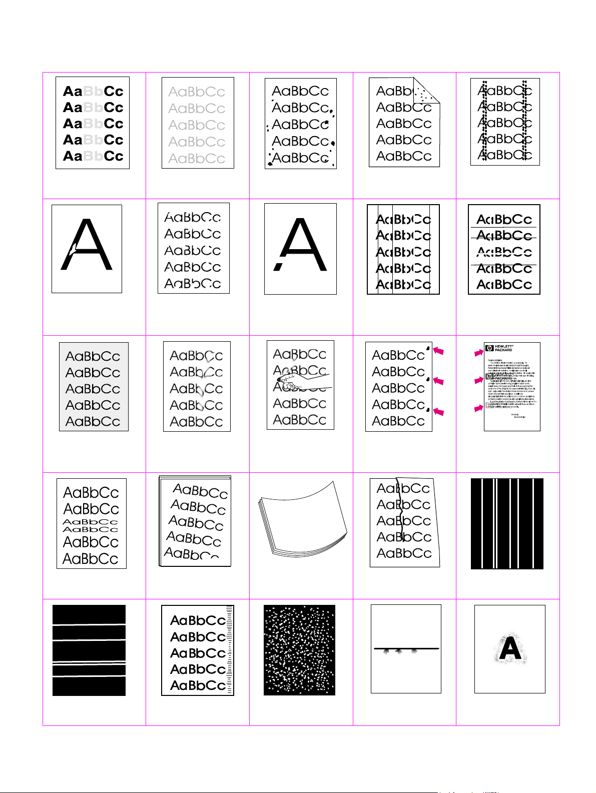
Image defect tables
Table 54. Print quality image defects
See “Light print (partial
page)” on page 313
See “Drop outs and
character voids” on
page 315
See “Grey background” on
page 317
See “Light print (entire
page)” on page 313
See “Drop outs and
character voids” on
page 315
See “Loose toner or toner
smear” on page 317
See “Specks or dots” on
page 314
See “Drop outs and
character voids” on
page 315
See “Loose toner or toner
smear” on page 317
See “Specks or dots” on
page 314
See “Lines” on page 316 See “Lines” on page 316
See “Repeating def ects and
repeating images” on
page 318
See “Specks or dots” on
page 314
See “Repeating def ects and
repeating images” on
page 318
See “Distorted images” on
page 318
See “White lines” on
page 320
See “Skew” on page 319 See “Curl or wave” on
See “Smudged lines (either
direction)” on page 320
page 319
See “White spots on black”
on page 321
See “Creases” on page 319 See “White lines” on
See “Scattered lines” on
page 321.
page 320
See “Blurred print” on
page 321.
Q2431-90912 Chapter 7 Troubleshooting 311
Page 86

Table 54. Print quality image defects (continued)
See “Black page” on
page 322.
See “Blank (or white) page”
on page 323.
See “Dark print” on
page 324.
312 Troubleshooting Q2431-90912
Page 87

Table 55. Light print (partial page)
Possible cause Recommended action(s)
The print cartridge is not installed
correctly.
Toner supply is low or toner cartridge
developer is defective.
Transfer roller is worn or contaminated
or maintenance might be due.
Table 56. Light print (entire page)
Possible cause Recommended action
Begin by perf orming the hal f self-tes t functional c hec k (see “Half self-test functional check” on page 310). If
the image on the print drum is light, proceed with actions 1, 2, 3, 6, and 7. If the drum image is normal,
proceed with actions 5, 6, and 8.
Toner supply is low.
EconoMode is on.
EconoMode sav es toner b y reducing the
dot density. The effect might appear to
be a print-quality problem in some
cases.
● Remove and then reinstall the print cartridge. The top cover
should completely close when the cartridge is fully seated.
1. Shake the print cartridge gently to redistribute the toner.
2. Replace the cartridge.
● Print a supplies status page (see“Supplies status page” on
page 242) and look at the maintenance kit gauge. If
maintenance is due, install a maintenance kit. For information
about ordering a maintenance kit, see chapter8.
Action 1
● Shake the print cartridge gently to redistribute the toner, or
replace the cartridge.
Action 2
● Turn EconoMode off.
Print density is set incorrectly
The media does not meet spec ifications.
The moisture content, conductivity, or
surface finish mi ght not wo rk correctl y
with the electrophotographic process.
The transfer roller is defective or not
installed correctly. If the transfer roller
loses conductivity, it cannot effectively
pull toner from the drum.
The high-voltage connector springs are
dirty or damaged.
The laser/scanner shutter door is not
opening corr ectly.
The power supply is defective. The
power supply contains the high-voltage
circuit.
Action 3
● Change the toner density (see“Print Quality submenu” on
page 46) to a darker setting and try the print job again.
Action 4
● Try a different paper lot.
Action 5
● Verify the transfer roller is installed correctly. If the transfer
roller is damaged, replace it. See “Transfer roller” on page138.
Action 6
● The high-voltage connectors protrude into the print cartridge
cavity. Clean the springs if they are dirty. Replace the spri ngs if
they are damaged or missing.
Action 7
1. Remove and reseat the print cartridge.
2. Verify that the laser/scanner shutter door can open properly.
If necessary, replace the laser/scanner assembly. See
“Laser/scanner assembly” on page 173.
Action 8
● Replace the power supply. See “Power supply” on page 188
Q2431-90912 Chapter 7 Troubleshooting 313
Page 88

Table 57. Specks or dots
Possible cause Recommended action
Specks
Specks might appear on a page after a jam has been cleared. Print two to three more pages and see if
they disappear.
There is dirt in the printer. 1. Print a few more pages an d see if the problem co rrec ts its el f.
The print cartridge has damaged
components.
The media does not m eet sp ecifi cation s
or is not stored properly.
The fuser rollers are worn out.
Dots (in the paper path direction)
The static eliminator teeth are dirty. ● Clean the static eliminator teeth with a small brush or
Poor contact between the static
eliminator teeth and the power supply.
The transfer roller is deformed or
deteriorated.
2. Clean the inside of the printer (see chapter 4)
3. Process a printer cleaning page. See “Running the cleaning
page manually” on page 56.
● Perform the half self-test functional check (see “Half self-test
functional che ck” on page 310). If the problem developed on the
print drum, replace the print cartridge.
1. Turn over the stack of media in the tray. Also try rotating the
media 180 degrees.
2. Check the media for type and quality. Replace the media,
and advise the customer to use the HP recommended
media and to store i t correc tly. See “Paper specificatio ns” on
page 9.
● Replace the fuser. See “Fuser” on page 162
compressed air.
● Clean the contacts, if they are dirty. If the problem persists after
cleaning, or the contacts are damaged or deformed, replace
them.
● Replace the transfer roller. See “Transfer roller” on page138.
The power supply is defective.
● Replace the power supply. See “Power supply” on page 188.
314 Troubleshooting Q2431-90912
Page 89

Table 58. Drop outs and character voids
Possible cause Recommended action(s)
Printing on the wrong side of the paper.
The label on the r eam of pa per indicates
which side to print on. The different
surface properties of some papers
might cause problems if the paper is
loaded wrong-side-up.
The media surface is too rough.
The media surface is too smooth for
proper toner adhesion.
Bad transparencies . T ransparenc ies can
have this problem because they are not
designed for proper toner adhesion.
The printers operating environment
does not meet specifications.
The fuser roller is dirty and is lifting part
of the image off of the paper.
Defective or nearly empty print
cartridge.
Wrong toner density setting.
Wrong fuser setting for media type.
Bad transfer roller. If the transfer roller
has finger oils on its surface, is dirty or
worn out, this problem can occur.
Poor high-voltage contact between the
power supply and the print cartridge or
transfer roll er.
The power supply is defective (low
transfer voltage).
1. Check the arrow on the paper wrapper. Make sure that the
paper loaded corresponds with the ar row pointing up in
tray 1, or pointing down in the other trays.
2. Turn over the stack of paper in the tray. Also try rotating the
stack 180 degrees. Do not fan the stack.
3. Check the paper (or other media) type and quality. Replace
the media and advise the customer to use the
recommended HPmedia and to store it correctly.
● Use paper with the correct finish (smoothness) to meet
HP specifications (see the HP LaserJet Printer Family Pape r
Specification Guide).
● Use paper with the correct finish (smoothness) to meet
HP specifications (see the HP LaserJet Printer Family Pape r
Specification Guide).
● Use hp-approved transparencies for monochrome LaserJet
printers (see the HP LaserJet Printer Family Paper Specification
Guide).
● Make sure the printer is installed in the proper environment.
See “Environmental specifications” on page 7.
● Process a cleaning page (see chapter 4). several pages might
be required if the fuser is very dirty.
● Replace the print cartridge.
● Access the print-quality menu at the control panel, and adjust
the toner density setting. See “Print Quality submenu” on
page 46. Make sure EconoMod e is set to of f.
● Access the configure device menu at the control panel, and
change the fuser mode setting or choose another media type.
See “Configure De vic e men u ” on page 44.
● Clean the transfer roller using a dry, lint-free cloth. Do not
touch the transf er roller w ith you r fingers . If the prob lem pe rsists,
replace the transfer roller. See “Transfer roller” on page 138.
● Inspect the contacts and clean them if they are dirty. Replace
them if they are damaged.
● Replace the power supply. See “Power supply” on page 188.
Q2431-90912 Chapter 7 Troubleshooting 315
Page 90

Table 59. Lines
Possible cause Recommended action(s)
Vertical lines (in the paper path direction)
The print cartridge is not seated
correctly.
● Remove the print cartridge and the reinstall it. The top cover
should be able to completely close when the print cartridge is
fully seated.
Defectiv e prin t cartridge.
● Perform the half self-test functional check. See “Half self-test
functional check” on page 310. If the defect developed on the
drum, replace the print cartridge.
Worn or dirty fuser roller.
● Process a printer cleaning page. See “Running the cleaning
page manuall y” on page 56. Several pages might be required if
the fuser is very dirty. If the problem persists, replace the fuser.
See “Fuser” on page 162.
Static eliminator teeth (just beyond the
transfer roller) are cont amin ated or
● Clean the teeth with a small brush or compressed air. Replace
the assembly if it is damaged.
defective.
Light is leaking into the printer.
● Make sure that all of the covers are in place. Move the printer
away from outside facing windows.
Horizontal lines (opposite the paper path direction)
Repetitive defect. If the lines are
repeated at a consistent interval down
the page, this is a repetitive defect.
Sharp random lines indicate a problem
with the laser/scanner control circu itry.
● Use the repetitive defect ruler to determine the cause of this
defect. See “Repetitive defects troubleshooting” on page 325.
● Replace the following in order:
1. Laser/scanner assembly. See “Laser/scanner assembly” on
page 173.
2. DC controller PCA. See “DC controller PCA” on page 181.
3. Cables between the DC controller and the laser/scanner
assembly.
4. Formatter assembly. See “Format ter assembly” on
page 161.
316 Troubleshooting Q2431-90912
Page 91
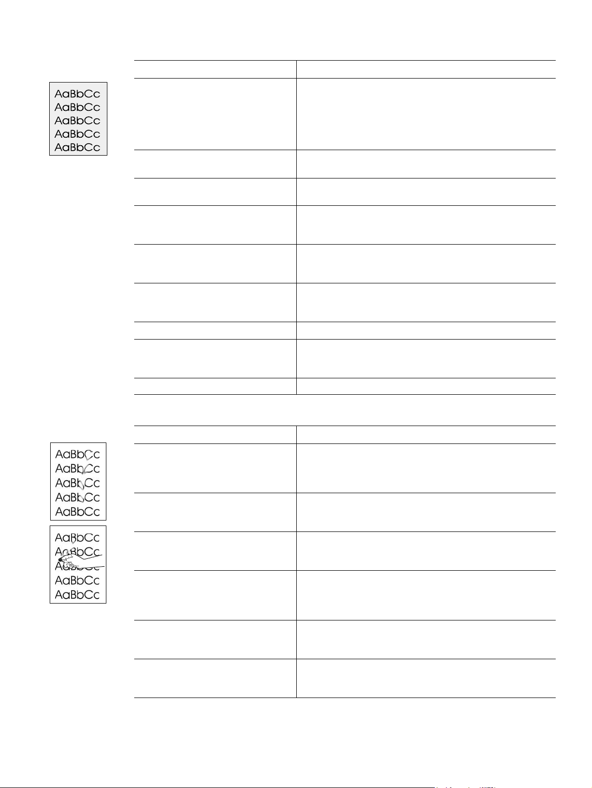
Table 60. Grey background
Possible cause Recommended action(s)
The media does no t meet speci ficati ons
or is not stored properly.
Inside of the printer is d irty (toner leaked
out of the print cartridge).
The printers operating environment
does not meet specifications.
Printing on enve lope seams . Printing on
an envelope seam can cause a
background scatter problem.
Wrong toner density setting.
The high transfer setting is turned off.
The print cartridge is defective.
The high-voltage connector springs are
dirty or damaged.
1. Turn over the stack of media in the tray. Also try rotating the
media 180 degrees.
2. Check the media for type and quality. Replace the media,
and advise the customer to use the HP recommended
media and to store it correct ly. See “Paper specificatio ns” on
page 9.
● Clean the inside of the printer (see chapter 4). Install a new
print cartridge.
● Make sure the printer is installed in the proper environment.
See “Environmental specifications” on page 7.
● Move the text to an area that has no seams.
● Access the print-quality menu at the control panel, and adjust
the toner density setting. See “Print Quality submenu” on
page 46. Make sure EconoMod e is set to of f.
● Access the print-quality menu at the control panel (see “Print
Quality submen u” on page 46). Select
TRANSFER=ON
● Replace the print cartridge.
● The high-voltage connectors protrude into the print cartridge
.
OPTIMIZE and set HIGH
cavity. Clean the springs if they are dirty. Replace the spri ngs if
they are damaged or missing.
The power supply is defective.
Table 61. Loose toner or toner smear
Possible cause Recommended action(s)
There is dirt in the printer. 1. Print a few more pag es an d s ee if the problem cor r ect s its elf.
The fuser roller is dirty.
The media surface is too rough or too
smooth.
Static eliminator teeth (just beyond the
transfer roller) are contaminated or not
grounded, which allows a static charge
to remain on the page.
Fuser is def ectiv e . The print wi ll smear if
the fuser dose nor heat sufficiently to
bond the toner to the paper.
The DC controller PCA is def ective . Th e
DC controller PCA re gulates the fuser
roller temperature.
● Replace the power supply. See “Power supply” on page 188
2. Clean the inside of the printer (see chapter 4)
3. Process a printer cleaning page. See “Running the clean ing
page manually” on page 56.
● Process a cleaning page (see “To run the cleaning page
manually” on page 56). Several pages might be required if the
fuser is very dirty.
● Use paper with the correct finish (smoothness) to meet HP
specifications (see the HP LaserJet Printer Family Paper
Specification Guide).
● Clean the teeth with a small brush or compressed air. Replace
the assembly if it is damaged.
● Replace the fuser. See “Fuser” on page 162.
● Replace the DC controller PCA. See“DC controller PCA” on
page 181.
Q2431-90912 Chapter 7 Troubleshooting 317
Page 92

Table 62. Repeating defects and repeating images
Possible cause Recommended action(s)
The print cartridge or fuser is damaged.
The circumferen ce of the
photoconductiv e drum ins ide of th e print
cartridge is 94.2 mm (3.7 inches). If the
defect repeats at thi s interval, the def ect
is associated with the drum.
1. Inspect the drum for scratches or other damage. Replace
the print cartridge for defects that repeat at 37.7 mm
(1.5 inches), 62.8 mm (2.5 inches), 54.0 mm (2.1 inches),
and/or 94.2 mm (3.7 inches).
2. Process a printer cleaning page. See “Running the cleaning
page manually” on page 56.
3. If the problem persists, and the defect repeats at the
Repetitive defects caused by the
LJ 4300 fuser roller repeat at 94.0 mm
(about 3.7 inches) Because the LJ 4300
fuser roller is just 2 mm (.07 inch)
75.0 mm (2.95 inches) or 94.0 mm (about 3.7 inches)
replace the fuser (see “Fuser” on page 162). For more
information about repetitive defects, see “Repetitive defects
troubleshooting” on page 325.
smaller than the photoconductive drum
it can be difficult to distinguish defects
caused by the photoconductive drum
from those caused by the LJ 4300 fuser
roller.
Dirty rollers. A dirty roller in the paper
● Examine and clean (or replace) the rollers in the paper path.
path can cause a repetitive defect.
Media does not m eet specificat ions. The
● Try a different paper.
surface might be too coarse, which can
cause repeating marks.
Pre-printed form paper is used.
● Some pre-printed forms (for example, letterheads) use an ink
that cannot stand up to the high temperatures in the fuser.
Check the media for type and quality. Replace the media, and
advise the customer to use the HP recommended media and to
store it correctly. See “Paper specifications” on page 9.
For more information about troubleshooting repeating defects, see “Repetitive defects troubleshooting” on page325.
Table 63. Distorted images
Possible cause Recommended action(s)
The media does not m eet sp ecifi cation s
or is not stored properly.
The printers operating environment
does not meet specifications.
Poor connection of the cables to the
laser/scanner assembly.
Poor connection of the cables to the
DC controller PCA.
The laser/scanner assembly is
defective.
Gears are worn, causing slippage or
jumping.
The print cartridge motor is defective.
HP LaserJet 4300 only
The DC controller PCA is defective.
1. Turn over the stack of media in the tray. Also try rotating the
media 180 degrees.
2. Check the media for type and quality. Replace the media,
and advise the customer to use the HP recommended
media and to store i t correc tly. See “Paper specificatio ns” on
page 9.
● Make sure the printer is installed in the proper environment.
See “Environmental specifications” on page7.
● Reseat the cables that are connected to the laser/scanner
assembly.
● Reseat the cables that are connected to the
DC controller PCA.
● Replace the laser/scanner. See “Laser/scanner assem bly” on
page 173.
● Inspect the gears that drive the print cartridge and fuser.
Replace the main driv e asse mb ly. See “Main drive assemb ly” on
page 186.
● Replace the print cartridge motor (HP LaserJet 4300 only).
See “Print-cartridge motor (HP LaserJet 4300 series printer
only)” on page 175.
● Replace the DC controller PCA. See “DC controller PCA” on
page 181.
318 Troubleshooting Q2431-90912
Page 93

Table 64. Skew
Possible cause Recommended action(s)
The media does no t meet speci ficati ons
or is not stored properly.
The media is not loaded properly or the
trays are not adjusted correctly.
The registration assembly is not
installed correctly or is damaged.
Table 65. Curl or wave
Possible cause Recommended action(s)
The media does no t meet speci ficati ons
or is not stored properly.
The printer’s operating environment
does not meet specifications.
Wrong output bin.
1. Turn over the stack of media in the tray. Also try rotating the
media 180 degrees.
2. Check the media for type and quality. Replace the media,
and advise the customer to use the HP recommended
media and to store it correct ly. See “Paper specificatio ns” on
page 9.
● Make sure that the media is loaded properly and that the
guides fit correctly against the sta ck.
● Make sure that the registration assembly is installed correctly. If
necessary, replace the registration assembly. See “Registration
assembly” on page 198.
1. Turn over the stack of media in the tray. Also try rotating the
media 180 degrees.
2. Check the media for type and quality. Replace the media,
and advise the customer to use the HP recommended
media and to store it correct ly. See “Paper specificatio ns” on
page 9.
● Make sure the printer is installed in the proper environment.
See “Environmental specifications” on page 7.
● Print to a different output bin (top or rear output bin).
Table 66. Creases
Wrong fuser setting for the media type.
● Access the configure device menu at the control panel, and
change the fuser mode setting or choose another media type.
See “Configure De vic e men u ” on page 44.
Possible cause Recommended action(s)
The media does no t meet speci ficati ons
or is not stored properly.
The printer’s operating environment
does not meet specifications.
The media is not loaded properly or the
trays are not adjusted correctly.
Wrong tray.
Wrong output bin.
Obstruction in the paper path. 1. Check the paper path for debris.
1. Turn over the stack of media in the tray. Also try rotating the
media 180 degrees.
2. Check the media for type and quality. Replace the media,
and advise the customer to use the HP recommended
media and to store it correct ly. See “Paper specificatio ns” on
page 9.
● Make sure the printer is installed in the proper environment.
See “Environmental specifications” on page 7.
● Make sure that the media is loaded properly and that the
guides fit correctly against the sta ck.
● Print from tray 1 when you use a difficult media.
● Print to the rear output bin.
2. Check for damaged components that might be creasing the
paper.
Q2431-90912 Chapter 7 Troubleshooting 319
Page 94

Table 67. White lines
Possible cause Recommended action(s)
White lines in the paper path
Toner supply i s lo w or th e print c artridge
is defective.
Dirt in the laser path.
1. Shake the print cartridge gently to redistribute the toner.
2. Replace the cartridge.
● Clean the laser path. Remove the la ser/scan ner assem bly (see
“Laser/scanner assembly” on page 173) and check f or dirt or
other obstructions in the beam path.
The fuser is defective.
Dirty mirror in the laser/scanner.
● Replace the fuser. See “Fuser” on page 162.
● Replace the laser/scanner assembly. See “Laser/scanner
assembly” on page 173
White lines opposite the paper path
The print drum is damaged. ● Replace the print cartridge.
The fuser roller is damaged.
Unstable laser beam or beam circuitry.
● Process a printer cleaning page. See “Running the cleaning
page manuall y” on page 56.
● If the problem persists, replace the fuser. See“Fuser” on
page 162.
● Replace the following in order:
1. Laser/scanner assembly. See “Laser/scanner assembly” on
page 173.
2. DC controller PCA. See “DC controller PCA” on page 181.
3. Cables between the DC controller PCA and the
laser/scanner assembly.
4. Formatter assembly. See “Format ter assembly” on
page 161.
Table 68. Smudged lines (either direction)
Possible cause Recommended action(s)
Paper path contamination or damage. 1. Perform the half self-test f unctional chec k. See “Half se lf-test
The print cartridge has passed its life
expectancy.
This type of defect mi ght also be a repetitive defect, See “Repetitiv e defects trouble sh ooti ng” on page 325.
functional check” on page 310. If the defect developed on
the drum, replace the print cartridge.
2. Process a printer cleaning page. See “Running the cleaning
page manually” on page 56. If the problem persists, replace
the fuser. See “Fuser” on page 162.
3. Check the tray 1 feed roller and the other tray’s rollers for
contamination. Clean or replace as necessary.
4. Check for other sources of contamination or damage in the
paper path and clean or replace as necessary.
● The print cartridge has an expected lif e of 12, 000 pages for the
HP LaserJet 4200 printer and 18,000 pages for the
HP LaserJet 4300 printer. Replace the print cartridge.
320 Troubleshooting Q2431-90912
Page 95

Table 69. White spots on black
Possible cause Recommended action(s)
The media does no t meet speci ficati ons
or is not stored properly.
The printers operating environment
does not meet specifications.
The print cartridge is defective.
Table 70. Scattered lines
Possible cause Recommended action(s)
The media does no t meet speci ficati ons
or is not stored properly.
The printers operating environment
does not meet specifications.
Wrong toner density setting.
1. Turn over the stack of media in the tray. Also try rotating the
media 180 degrees.
2. Check the media for type and quality. Replace the media,
and advise the customer to use the HP recommended
media and to store it correct ly. See “Paper specificatio ns” on
page 9
● Make sure the printer is installed in the proper environment.
See “Environmental specifications” on page 7.
● Replace the print cartridge.
1. Turn over the stack of media in the tray. Also try rotating the
media 180 degrees.
2. Check the media for type and quality. Replace the media,
and advise the customer to use the HP recommended
media and to store it correct ly. See “Paper specificatio ns” on
page 9
● Make sure the printer is installed in the proper environment.
See “Environmental specifications” on page 7.
● Access the print-quality menu at the control panel, and adjust
the toner density setting. See “Print Quality submenu” on
page 46.
The high transfer setting is turned off.
The line detail setting is turned off.
Table 71. Blurred print
Possible cause Recommended action(s)
The media does no t meet speci ficati ons
or is not stored properly.
The printers operating environment
does not meet specifications.
Wrong toner density setting.
The high transfer setting is turned off.
The line detail setting is turned off.
● Access the print-quality menu at the control panel (see “Print
Quality submen u” on page 46). Select
TRANSFER=ON
● Access the print-quality menu at the control panel (see “Print
.
Quality submen u” on page 46). Select
DETAIL=ON
.
OPTIMIZE and set HIGH
OPTIMIZE and set LINE
1. Turn over the stack of media in the tray. Also try rotating the
media 180 degrees.
2. Check the media for type and quality. Replace the media,
and advise the customer to use the HP recommended
media and to store it correct ly. See “Paper specificatio ns” on
page 9
● Make sure the printer is installed in the proper environment.
See “Environmental specifications” on page 7.
● Access the print-quality menu at the control panel, and adjust
the toner density setting. See “Print Quality submenu” on
page 46.
● Access the print-quality menu at the control panel (see “Print
Quality submen u” on page 46). Select
TRANSFER=ON
● Access the print-quality menu at the control panel (see “Print
.
Quality submen u” on page 46). Select
DETAIL=ON
.
OPTIMIZE and set HIGH
OPTIMIZE and set LINE
Q2431-90912 Chapter 7 Troubleshooting 321
Page 96

Table 72. Black page
Possible cause Recommended action(s)
The print cartridge is defective. ● Replace the print cartridge.
The high-voltage connector springs are
dirty or damaged.
The laser beam drive circuit or
high-voltage circuit is defective (it is n ot
supplying the correct voltage).
The laser/scanner assembly is defective
(it is turning the laser beam on
continuously).
Connectors between the laser/scanner
assembly and the DC controller PCA
are not seated correc tly or are defective .
● The high-voltage connectors protrude into the print cartridge
cavity. Clean the springs if they are dirty. Replace the springs if
they are damaged or missing.
1. Check the cables between the DC controller PCA and the
high-voltage circuitry (part of the power supply).
2. Replace the power supply. See “Power supply” on
page 188.
3. Replace the DC controller PCA. See “DC controller PCA” on
page 181.
● Replace the laser/scanner assembly. See “Laser/scanner
assembly” on page 173.
● Inspect and reseat the connectors. If necessary, replace the
cables.
322 Troubleshooting Q2431-90912
Page 97

Table 73. Blank (or white) page
Possible cause Recommended action(s)
Software configuration (intermittent
problem).
Network configuration. Some sharing
devices on networks might generate a
blank page as a print job separator.
Multiple feeds. The printer might be
feeding two or more pages at once
(intermittent problem).
The sealing tape was left in the print
cartridge.
The print cartridge is empty or d efective .
The laser/scanner shutter door is not
opening corr ectly.
No transfer-roller voltage.
The high-voltage connector springs are
dirty or damaged.
No drum ground path.
● Make sure that the application is not sending incorrect page-
length requests or extra page-eject commands.
● Check with the network administrator.
● Remove the media from the tray and flex the stack in one
direction and then the other to separate the pages. Do not fan
the stack. Replace the stack in the tray.
● Remove the sealing tape.
● Replace the print cartridge.
1. Remove and reseat the print cartridge.
2. Verify that the las er/s c ann er sh utte r doo r can open properly.
If necessary, replace the laser/scanner assembly. See
“Laser/scanner assembly” on page 173.
● Without transfer-roller vol tage , toner does not tr ansfer correctly
from the surface of the drum to the paper. Perform the half
self-test functional check (see “Half self-test functional check”
on page 310) to check the electrophotographic process. If
necessary, replace the transfer roller. See “Transfer roller” on
page 138.
● The high-voltage connectors protrude into the print cartridge
cavity. Clean the springs if they are dirty. Replace the spri ngs if
they are damaged or missing.
● With no drum ground path, the drum cannot discharge. The
negative charge on the drum repels toner, and leaves a nearlywhite page (possibly with bubbled print). Check the drum ground
that runs from the contact point in the center of the print drum.
High-voltage circuit is defective.
Defective laser/scanner cable.
● Replace the power supply. See “Power supply” on page 188.
● Low-level signals that are exchanged between the laser/
scanner assembl y and the DCcontroller PCA might be affecting
the laser output. Replace the laser/scanner cables.
Q2431-90912 Chapter 7 Troubleshooting 323
Page 98

Table 74. Dark print
Possible cause Recommended action(s)
Wrong toner density setting. ● Access the print-quality menu at the control panel, and adjust
the toner density setting. See “Print Quality subm en u” on
page 46.
The print cartridge drum is close to the
end of its expected life.
The media does not m eet sp ecifi cation s
or is not stored properly.
Poor high-voltage contact to the power
supply.
Defectiv e las er/scanner assembly.
Defectiv e hig h-voltage circuit.
● Replace the print cartridge.
1. Turn over the stack of media in the tray. Also try rotating the
media 180 degrees.
2. Check the media for type and quality. Replace the media,
and advise the customer to use the HP recommended
media and to store i t correc tly. See “Paper specificatio ns” on
page 9
● Clean the contacts if they are dirty . If the probl em persis ts after
cleaning, or the contacts are damaged or deformed, replace
them.
● Replace the laser/scanner assembly. See “Laser/scanner
assembly” on page 173.
● Replace the power supply. See “Power supply” on page 188
324 Troubleshooting Q2431-90912
Page 99

Repetitive defects troubleshooting
Defects on printer rollers can cause image defects to appear at regular intervals on the page.
These defects appear at regular intervals that correspond to the circumference of the roller
causing the defect. Measure the distance between defects that recur on a page. Use table 75 or
the repetitive defect ruler (figure 207) to determine which roller is causing the defect. To resolve
the problem, try cleaning the roller first. If the roller is still dirty after cleaning or if it is damaged,
replace the indicated part.
CAUTION Do not use solvents or oils to clean rollers. Instead, rub the roller with lint-free paper. If dirt is
difficult to remove, rub the roller with lint-free paper dampened with water.
Table 75. Repetitive defects
Roller Distance between defects Replacement part
Primary charging roller 37.7 mm (1.5 inches) print cartridge
Developer roller* 62.8 mm (2.5 inches) print cartridge
Fuser 75.0 mm (2.95 inches; HP LaserJet 4200)
94.0 mm (3.75 inches; HP LaserJet 4300)
Photosensitive drum 94.2 mm (3.75 inches) print cartridge
*The dev el oper ro ller c ircum f eren ce is 62.8mm (2.5 inches). This defect will most lik el y rep eat a t inte rvals
of 54.0 mm (2.125 inches) because of the way it is geared.
Fuser
Note Defects on the tray pickup rollers or the tray 1 pickup roller do not cause a repetitive defect.
Defects on these rollers cause a defect to appear only on the leading edge of the image.
First occurrence of the defect
37.7 mm (1.5 inches) primary chargi ng roller
*Note: The developer
roller circumference is
62.83 mm (2.5 inches).
This defect will most
likely repeat at
intervals of 54.0 mm
(2.15 inches) because
of the way it is geared.
54.0 mm (2.125 inches) developer roller (see note)*
62.8 mm (2.5 inches) developer roller (see note)*
75.0 mm (2.95 inches) fuser (HP LaserJet 4200)
94.0 mm (3.75 inches) fuser (HP LaserJet 4300)
94.2 mm (3.75 inches) photosensitive drum
Figure 207. Repetitive defect ruler
Q2431-90912 Chapter 7 Troubleshooting 325
Page 100

Troubleshooting the stacker and the stapler/stacker
Overview
When troubleshooting the stacker or stapler/stacker it might be difficult to distinguish whether the
malfunction relates to the stacker, stapler/stacker or to the printer. The troubleshooting
procedures in this section assume the stacker or stapler/stacker is installed on a printer that is
working normally . Always correct any printer errors before attempting to troubleshoot the stacker
or stapler/stacker. Stacker and stapler/stacker errors fall into four groups:
● Jam errors
● Paper transport errors
● Malfunction errors
● Component errors
Jam and transport errors result in media not successfully moving from the printer through the
stacker or stapler/stacker. Malfunction errors result in the non- or mis-operation of the stacker or
stapler/stacker. Component errors are the result of an internal component failure. Component
errors messages will appear on the control-panel display. For more information about control
panel messages, see “Alphabetical printer messages” on page 258 and “Numerical printer
messages” on page 274.
Initial checks
❏ Inspect the stacker or stapler/stacker connector on the unit and on the printer. Verify that
these connectors are not damaged, and that the stacker or stapler/stacker is installed
correctly and fully seated. If the stacker or stapler/stacker is installed with the printer power
on, you must turn the power off and then back on again for the stacker or stapler/stacker to
operate.
❏ Verify that the environmental specifications are met. These specifications are the same for
the stacker and stapler/stacker as for the printer. See “Environmental specifications” on
page 7.
❏ Verify that the media being used meets HP recommendation. See “Supported sizes and
weights of media” on page 10 and “Supported types of media” on page 14.
❏ Verify that any printer errors are corrected before troubleshooting the stacker or stapler/
stacker. The printer must be operating normally to troubleshoot the stacker or stapler/stacker .
See “Alphabetical printer messages” on page 258 and “Numerical printer messages” on
page 274.
❏ If the stacker or stapler/stacker was recently moved from a cold environment (for example, a
warehouse) into a warm room, it may develop problems due to condensation. If condensation
occurs, either wipe off the parts with a dry, lint-free cloth, or leave the stacker or stapler/
stacker turned on for 10 to 20 minutes.
326 Troubleshooting Q2431-90912
 Loading...