

Page 1

6 Removing and replacing parts
Contents
Removal and replacement strategy . . . . . . . . . . . . . . . . . . . . . . . . . . . . 133
Required tools . . . . . . . . . . . . . . . . . . . . . . . . . . . . . . . . . . . . . . . . . . 133
Before performing service . . . . . . . . . . . . . . . . . . . . . . . . . . . . . . . . . 133
After completing service . . . . . . . . . . . . . . . . . . . . . . . . . . . . . . . . . . 133
Screws used in the printer. . . . . . . . . . . . . . . . . . . . . . . . . . . . . . . . . 134
Parts-removal tree. . . . . . . . . . . . . . . . . . . . . . . . . . . . . . . . . . . . . . . 135
Printer input tray, and cabinet wheel locks . . . . . . . . . . . . . . . . . . . . 136
User-replaceable parts . . . . . . . . . . . . . . . . . . . . . . . . . . . . . . . . . . . . . . 137
Print cartridge . . . . . . . . . . . . . . . . . . . . . . . . . . . . . . . . . . . . . . . . . . 137
Transfer roller . . . . . . . . . . . . . . . . . . . . . . . . . . . . . . . . . . . . . . . . . . 138
Tray 1 pickup roller . . . . . . . . . . . . . . . . . . . . . . . . . . . . . . . . . . . . . . 139
Tray 1 separation pad . . . . . . . . . . . . . . . . . . . . . . . . . . . . . . . . . . . . 140
Tray 2 feed rollers . . . . . . . . . . . . . . . . . . . . . . . . . . . . . . . . . . . . . . . 141
Covers, tray 1, and the rear output bin . . . . . . . . . . . . . . . . . . . . . . . . . . 143
Accessory covers and the tray 2 extension door. . . . . . . . . . . . . . . . 143
Formatter cover . . . . . . . . . . . . . . . . . . . . . . . . . . . . . . . . . . . . . . . . . 145
Top cover. . . . . . . . . . . . . . . . . . . . . . . . . . . . . . . . . . . . . . . . . . . . . . 146
Right-side cover. . . . . . . . . . . . . . . . . . . . . . . . . . . . . . . . . . . . . . . . . 149
Left-side cover. . . . . . . . . . . . . . . . . . . . . . . . . . . . . . . . . . . . . . . . . . 151
Tray 1 . . . . . . . . . . . . . . . . . . . . . . . . . . . . . . . . . . . . . . . . . . . . . . . . 152
Rear output bin . . . . . . . . . . . . . . . . . . . . . . . . . . . . . . . . . . . . . . . . . 155
Control-panel display . . . . . . . . . . . . . . . . . . . . . . . . . . . . . . . . . . . . . . . 156
Control-panel overlay . . . . . . . . . . . . . . . . . . . . . . . . . . . . . . . . . . . . 156
Control-panel assembly. . . . . . . . . . . . . . . . . . . . . . . . . . . . . . . . . . . 157
Internal components . . . . . . . . . . . . . . . . . . . . . . . . . . . . . . . . . . . . . . . . 160
Firmware DIMM. . . . . . . . . . . . . . . . . . . . . . . . . . . . . . . . . . . . . . . . . 160
Formatter assembly. . . . . . . . . . . . . . . . . . . . . . . . . . . . . . . . . . . . . . 161
Fuser . . . . . . . . . . . . . . . . . . . . . . . . . . . . . . . . . . . . . . . . . . . . . . . . . 162
Output delivery assembly . . . . . . . . . . . . . . . . . . . . . . . . . . . . . . . . . 163
Duplexing pendulum assembly . . . . . . . . . . . . . . . . . . . . . . . . . . . . . 165
Tray 2 media-size sensor . . . . . . . . . . . . . . . . . . . . . . . . . . . . . . . . . 167
Main cooling fan (left side). . . . . . . . . . . . . . . . . . . . . . . . . . . . . . . . . 168
Cooling fan (right side; HP LaserJet 4300 series printer only) . . . . . 170
Laser/scanner assembly . . . . . . . . . . . . . . . . . . . . . . . . . . . . . . . . . . 173
Print-cartridge motor (HP LaserJet 4300 series printer only) . . . . . . 175
Main motor. . . . . . . . . . . . . . . . . . . . . . . . . . . . . . . . . . . . . . . . . . . . . 177
Tray 2 lifter-drive assembly . . . . . . . . . . . . . . . . . . . . . . . . . . . . . . . . 179
DC controller PCA. . . . . . . . . . . . . . . . . . . . . . . . . . . . . . . . . . . . . . . 181
Paper-pickup assembly, . . . . . . . . . . . . . . . . . . . . . . . . . . . . . . . . . . 183
Main drive assembly . . . . . . . . . . . . . . . . . . . . . . . . . . . . . . . . . . . . . 186
Power supply. . . . . . . . . . . . . . . . . . . . . . . . . . . . . . . . . . . . . . . . . . . 188
Paper-feed belt assembly . . . . . . . . . . . . . . . . . . . . . . . . . . . . . . . . . 191
Q2431-90912 Chapter 6 Removing and replacing parts 131
Page 2

Tray 1 paper-pickup assembly . . . . . . . . . . . . . . . . . . . . . . . . . . . . . 192
Paper feed assembly . . . . . . . . . . . . . . . . . . . . . . . . . . . . . . . . . . . . 195
Registration assembly . . . . . . . . . . . . . . . . . . . . . . . . . . . . . . . . . . . 198
Transfer assembly . . . . . . . . . . . . . . . . . . . . . . . . . . . . . . . . . . . . . . 200
Accessories . . . . . . . . . . . . . . . . . . . . . . . . . . . . . . . . . . . . . . . . . . . . . . 204
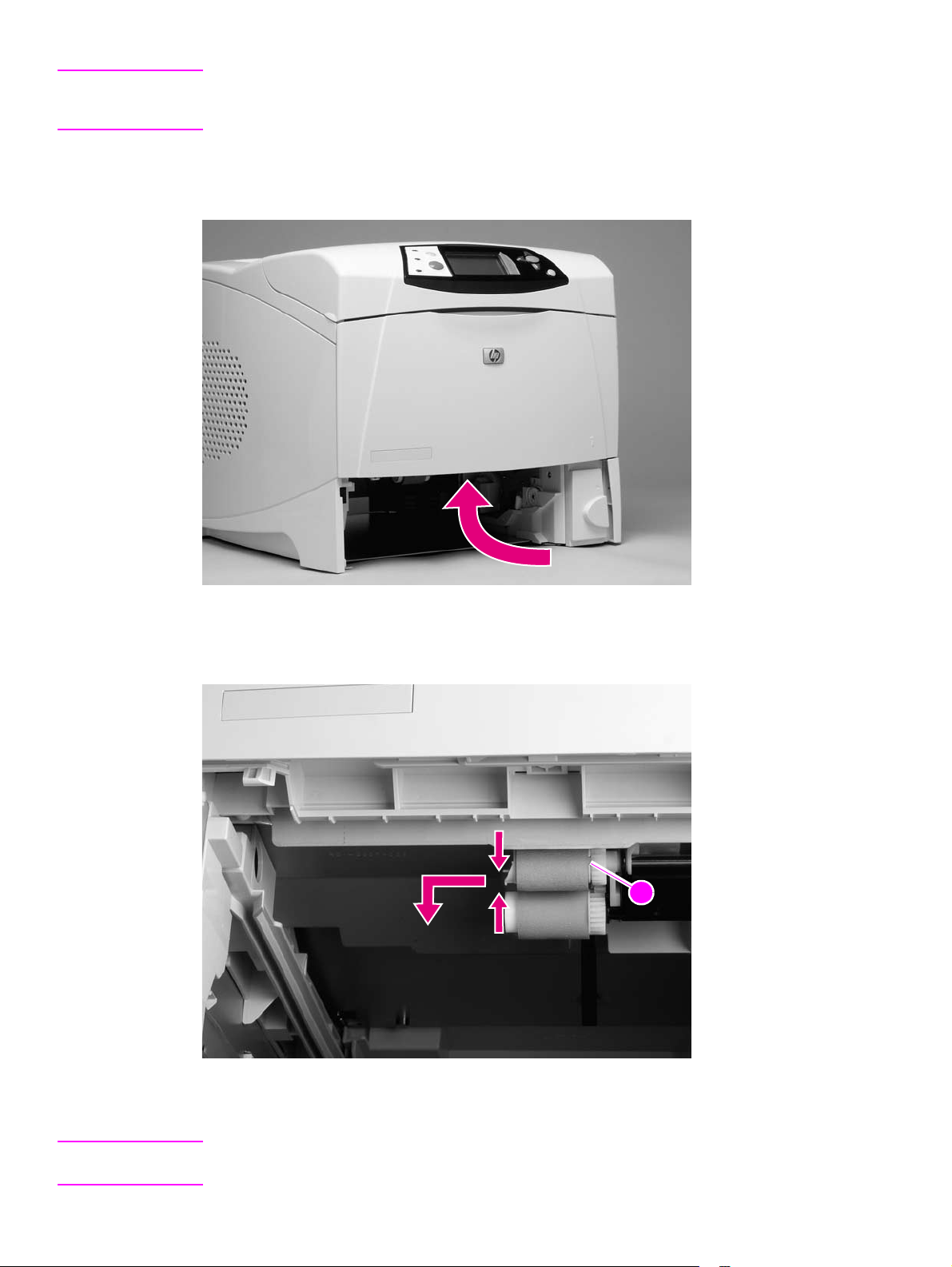
500-sheet feeder assembly . . . . . . . . . . . . . . . . . . . . . . . . . . . . . . . 204
500-sheet feed rollers . . . . . . . . . . . . . . . . . . . . . . . . . . . . . . . . . 204
500-sheet feeder right-side cover . . . . . . . . . . . . . . . . . . . . . . . . 204
500-sheet feeder control PCA. . . . . . . . . . . . . . . . . . . . . . . . . . . 207
500-sheet feeder media-size sensor. . . . . . . . . . . . . . . . . . . . . . 208
500-sheet feeder lifter-drive assembly . . . . . . . . . . . . . . . . . . . . 209
500-sheet feeder paper-pickup drive assembly . . . . . . . . . . . . . 210
1,500-sheet feeder assembly. . . . . . . . . . . . . . . . . . . . . . . . . . . . . . 214
1,500-sheet feeder feed rollers . . . . . . . . . . . . . . . . . . . . . . . . . . 214
1,500-sheet feeder separation roller . . . . . . . . . . . . . . . . . . . . . . 214
1,500-sheet feeder door . . . . . . . . . . . . . . . . . . . . . . . . . . . . . . . 215
1,500-sheet feeder rear cover. . . . . . . . . . . . . . . . . . . . . . . . . . . 217
1,500-sheet feeder right-side cover. . . . . . . . . . . . . . . . . . . . . . . 218
1,500-sheet feeder control PCA . . . . . . . . . . . . . . . . . . . . . . . . . 220
1,500-sheet feeder media-size sensor . . . . . . . . . . . . . . . . . . . . 221
1,500-sheet feeder lifter-drive assembly . . . . . . . . . . . . . . . . . . . 222
1,500-sheet feeder paper-pickup drive assembly . . . . . . . . . . . . 225
132 Removing and replacing parts Q2431-90912
Page 3

Removal and replacement strategy
This chapter describes how to remove, replace, and reassemble the major assemblies of the
printer. Replacement is generally the reverse of removal. To identify the left side and right side of
the printer, face tray 1 on the front of the unit.
WARNING! Unplug the power cord from the power outlet (at the wall receptacle) before attempting to service
the product. If you do not follow this warning, severe injury can result. Certain functional checks
during troubleshooting might require power to be supplied to the product. However, all power
should be turned off and the product should be unplugged when you remove any product
assemblies or components. Never operate or service the printer when the protective cover is
removed from the laser/scanner assembly. The reflected beams, although invisible, can damage
your eyes.
CAUTION The product contains components that are sensitive to electrostatic discharge (ESD). Always
perform service work at an ESD-protected workstation. If an ESD-protected workstation is not
available, discharge body static by grasping the printer chassis before touching an
ESD-sensitive component. Ground the printer chassis before servicing the product.
Required tools
● #2 Phillips screwdriver
● small flat-blade screwdriver
● needle-nose pliers
● ESD mat (if available; see the ESD caution above)
● penlight (optional)
● Tape (optional)
CAUTION A PoziDriv screwdriver will damage screw heads on the product. Use a #2 Phillips screwdriver.
Before performing service
● If possible, print a menu map and configuration page. See the “Menu map” on
page 240 and“Configuration page” on page 241.
● Remove all of the accessories and print media, the print cartridge, and tray 2 from
the product.
● Unplug the power cord from the power outlet at the wall receptacle.
● Place the product on an ESD mat, if one is available. If an ESD-protected
workstation is not available, discharge body static by grasping the printer chassis
before touching an ESD-sensitive component. Ground the printer chassis before
servicing the product
After completing service
● Reinstall the print cartridge (remove the print cartridge prior to transporting the
printer back to the customer).
● Reconnect all cables to the product.
● Replace all of the accessories and load the media.
● Print a configuration page and verify that the latest firmware is installed on the
printer. See “Downloading a remote firmware update” on page 63.
Q2431-90912 Chapter 6 Removing and replacing parts 133
Page 4
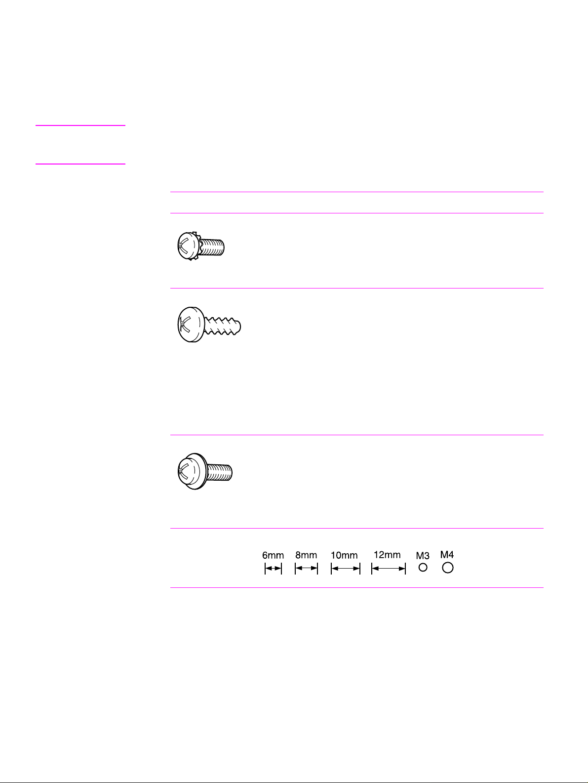
Screws used in the printer
This table describes the screws used in the printer and provides guidelines to help determine
where each type of screw is used. The screws can vary in length depending on the thickness of
the material that is being fastened.
Always note where each type of screw is located and replace each one in its original location.
Hint When you are disassembling the product, place the screws into the chassis holes from which they
were removed. This prevents their loss, and ensures that the proper type and length of screw for
each location is used when the product is reassembled.
Table 36. Common fasteners used in this product
Drawing and description Purpose
This screw is used to f asten metal
to metal when good electrical
contact is needed. This screw
also provides high resistance to
loosening.
Phillips machine screw with captive star washer
This screw i s used to f asten sheet
metal or plastic to plastic frames
(the deep, coarsely spaced
threads provide an increased
holding capability while
Phillips screw with self-tapping threads
decreasing the possibility of
stripping the target hole).
Reinstal note: To install a self-tapping screw, first turn it counterclockwise to align it with the existing
thread pattern, and then carefully turn it clockwise to tighten it. You will feel resistance and hear the screw
click when it engages the existing threads in the hole. Do not overtighten the screw. If a self-tapping screwhole becomes stripped, repair the screw-hole or replace the affected assembly.
This screw i s used to f asten sheet
metal parts to the sheet metal
chassis. It spans large clearance
holes and distributes the load by
increasing the bearing surface.
Phillips washer-head machine screw with a broad, flat
washer attached to the screw head
Screw measurement guide
134 Removing and replacing parts Q2431-90912
Page 5

Parts-removal tree
Use the following diagram to determine the order in which parts must be removed.
Print cartridge
Transfer roller
Control-panel overlay
Tray 1
Tray 2 feed rollers
Rear output bin
Formatter cover
Firmware DIMM
Formatter assembly (2 machine screws)
Accessory covers and the tray 2 extension door
Fuser
Tray 1 pickup roller
Tray 1 separation pad
Top cover
Note Some components in the parts-removal tree have a
Control-panel assembly
Right-side cov e r
superscript number listed next to the component name
(for example, “Right-side cover
1
”). The superscript
indicates that this component must be removed to gain
access to the transfer assembly and to the registration
roller assembly. Components with superscript letters are
removed in numerical order.
1
Components listed with superscripts
Left-side cover
7
Components listed with superscripts
Note: The formatter assembly and fuser are only listed once, but they must
be removed to gain access to some of the other components.
Tray 2 media-size sensor
Tray 2 lifter-drive assembly
Cooling fan (right side; HP LaserJet 4300 only)
Laser/scanner
Paper-pickup assembly
3
Print-cartridge motor (HP LaserJet 4300 only)
Main motor
DC controller assembly
5
Main drive assembly
1, 2, 5, 6
6
Registration-roller assembly
Output delivery assembly
8
Duplexing pendulum assembly
Main coolin g fan (left side)
Power supply
9
Paper-feed assembly
Tray 1 pickup assembly
1, 3, 4, 5, 6, 7, 8, 9, 10
10
Transfer assembly
2
4
Q2431-90912 Chapter 6 Removing and replacing parts 135
Page 6
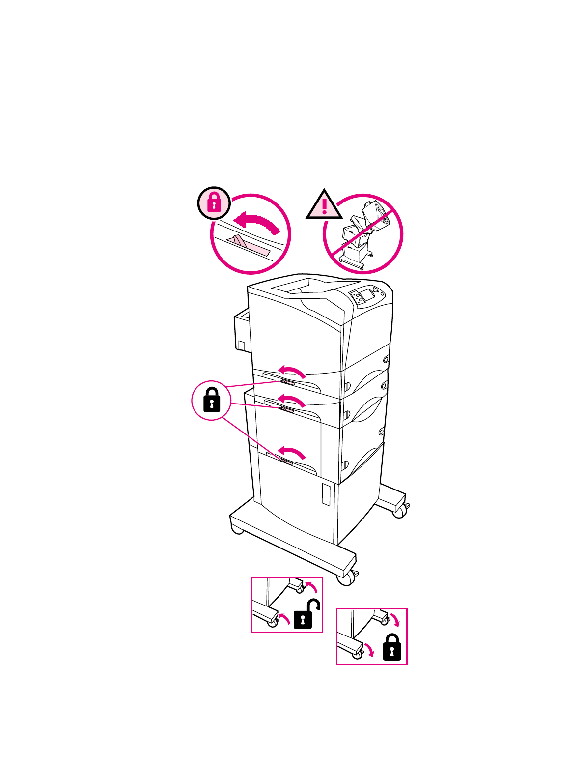
Printer input tray, and cabinet wheel locks
When the printer and input trays are placed on the cabinet stand, the printer and trays must be
locked together to prevent them from tipping over. This is not necessary (but it is recommended)
if the printer and trays are placed on a level work surface. When servicing the printer and
accessories, unlatch the locking mechanism and separate the printer and its accessory
components.
The cabinet stand includes lock for the wheels at its base. Make sure that the wheels are locked
when the printer is in place. The wheels should be unlocked only when the printer is being
relocated.
Figure 58. Location of printer, input trays, and cabinet wheel locks
136 Removing and replacing parts Q2431-90912
Page 7
User-replaceable parts
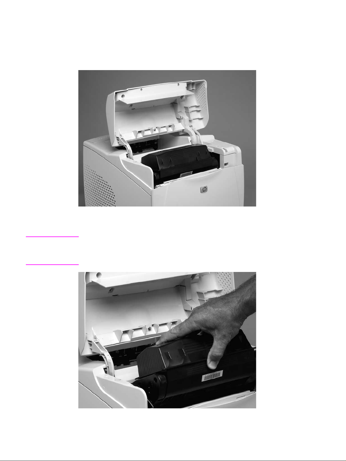
Print cartridge
1. Open the control-panel door.
Figure 59. Print cartridge (1 of 2)
2. Firmly grasp the print cartridge and pull it up and out of the printer.
CAUTION Do not expose the print cartridge to bright light or direct sunlight for long periods of time. This can
damage the cartridge, which will result in print-quality defects. If the cartridge must be removed
from the printer for an extended amount of time, cover it and keep it out of bright light or direct
sunlight.
Figure 60. Print cartridge (2 of 2)
Q2431-90912 Chapter 6 Removing and replacing parts 137
Page 8
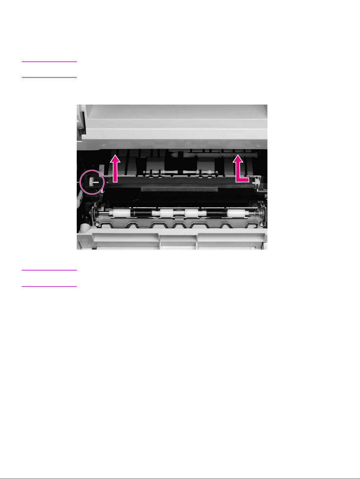
Transfer roller
1. Open the control-panel door and tray 1.
CAUTION Do not touch the black rubber on the roller. Skin oils on the roller can cause print-quality problems.
The use of disposable gloves is recommended when you remove the transfer roller.
2. Use a flat-blade screwdriver to lift the left end of the metal shaft out of place near the blue
gear. Slide the transfer roller to the left to remove it.
Figure 61. Transfer roller
Reinstall note When you install the transfer roller, make sure that the black collar on the left side is oriented
correctly, with the open end face down (the solid end is face up).
138 Removing and replacing parts Q2431-90912
Page 9
Tray 1 pickup ro ller
Note If the optional envelope feeder accessory is installed, press the release button that is on the left
side and remove it. Then proceed to step 2.
1. Remove the front accessory cover (callout 1).
11
Figure 62. Tray 1 pickup roller (1 of 2)
2. Release the pickup roller by sliding apart the latches that are located on each side at the top
of the roller. Lift the roller out of the opening.
222
Figure 63. Tray 1 pickup roller (2 of 2)
Reinstall note When you install the pickup roller, place the two pivot pins in the lower mounting slots (callout 2)
and rotate the roller into the printer until it snaps into place.
Q2431-90912 Chapter 6 Removing and replacing parts 139
Page 10
Tray 1 separation pad
Note If the optional envelope feeder accessory is installed, press the release button that is on the left
side and remove it. Then proceed to step 2.
1. Remove the front accessory cover (not shown). See “Accessory covers and the tray 2
extension door” on page 143.
2. Insert the tip of a a small flat-blade screwdriver under the tray 1 separation pad.
3. Carefully twist the screwdriver to dislodge the separation pad. Remove the tray 1 separation
pad.
Figure 64. Tray 1 separation pad
140 Removing and replacing parts Q2431-90912
Page 11
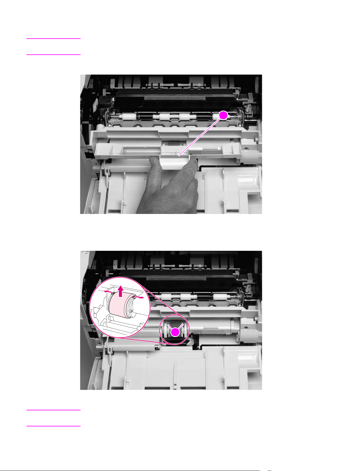
Tray 2 feed rollers
1. Remove tray 2 and place it on a level work surface. Locate and open the cover (arrow) that is
next to the roller in tray 2.
Figure 65. Tray 2 feed rollers (1 of 4)
2. Pinch the blue latch that is on the left side of the roller. Slide the roller off of the shaft
(arrows).
11
Figure 66. Tray 2 feed rollers (2 of 4)
CAUTION When you install the roller, make sure that it locks into place. Verify that the roller is correctly
oriented, and that the round, black spacer next to the roller is correctly positioned against the
locking pin on the shaft (callout 1).
Q2431-90912 Chapter 6 Removing and replacing parts 141
Page 12
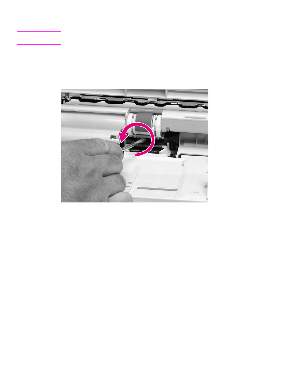
WARNING! Do not allow the front of the printer to extend beyond the edge of the work surface. The printer
can become unbalanced and fall, which can cause damage to the printer or personal injury to the
service technician.
3. Move the front of the printer to the edge of the work surface for better access to the feed
roller. To find the rollers, look up into the inside of the opening that was created when you
removed tray 2.
Figure 67. Tray 2 feed rollers (3 of 4)
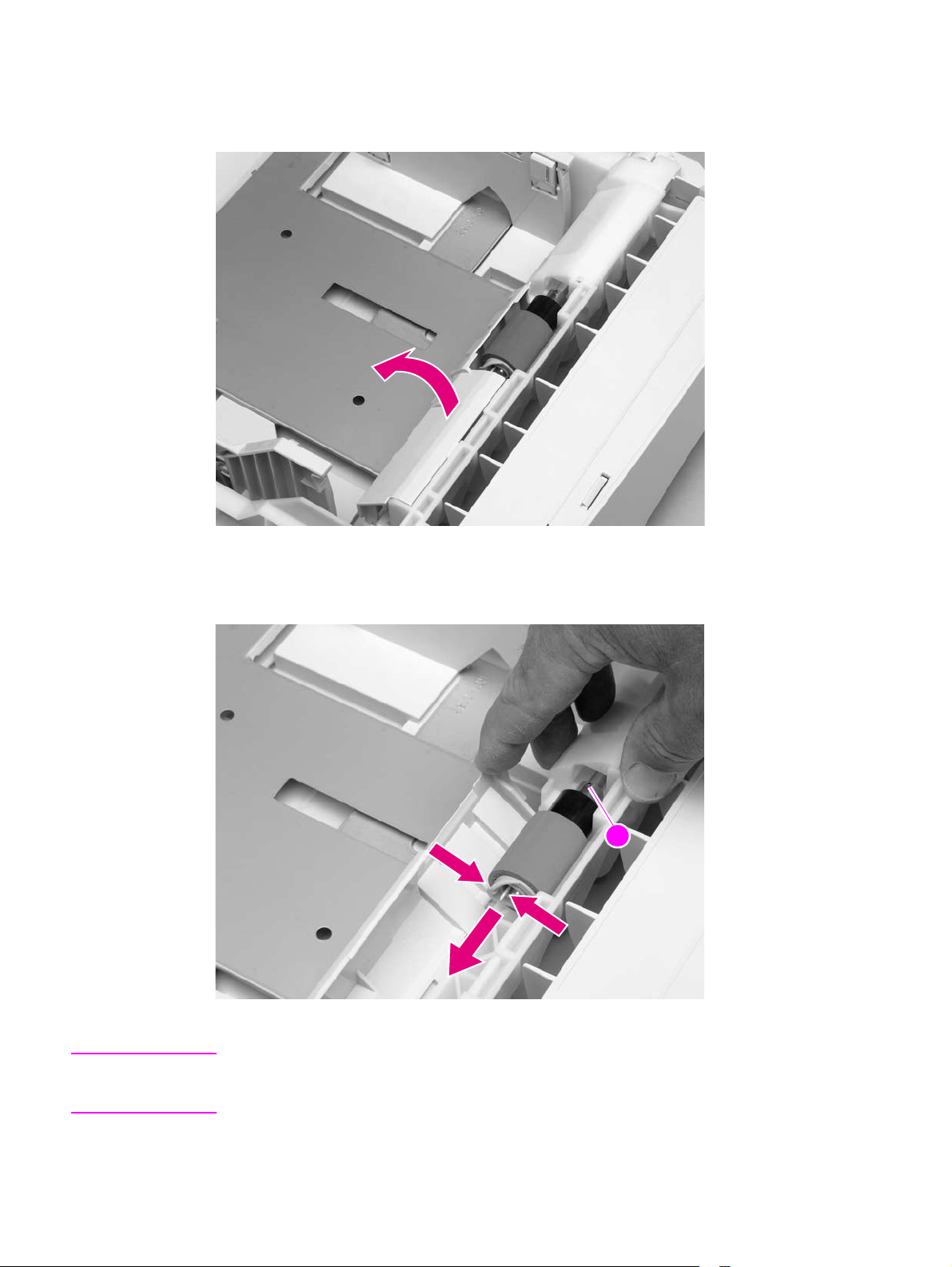
4. Pinch the blue latch on the left side of the feed roller. Slide the roller off of the shaft. You
might need to rotate the roller in order to pinch the latch.
22
Figure 68. Tray 2 feed rollers (4 of 4)
5. Repeat the previous step for the remaining white pickup roller.
Reinstall note When you install a roller, make sure that it locks into place on the tabs that are on the drive gear
(callout 2).
142 Removing and replacing parts Q2431-90912
Page 13
Covers, tray 1, and the rear output bin
Accessory covers and the tra y 2 extension door
Note Accessory covers will not be in place if any installed accessories (for example, the optional
stapler/stacker) have been removed to service the printer.
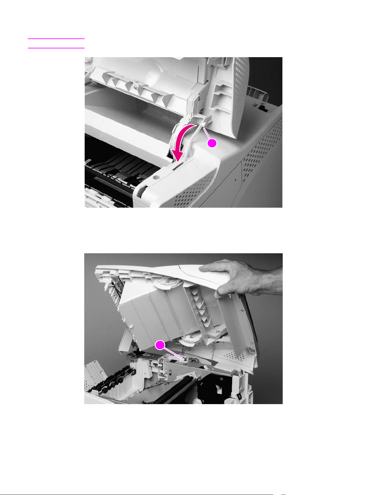
1. Grasp the top accessory cover (the mounting position for the optional stapler/stacker or
stacker). Rotate the cover toward the front of the printer to release it, and then lift it up to
remove it.
Figure 69. Accessory covers (1 of 4)
2. Open tray 1. Grasp the front accessory cover (the mounting position for the optional
envelope feeder) and pull it straight out of the printer.
Figure 70. Accessory covers (2 of 4)
Q2431-90912 Chapter 6 Removing and replacing parts 143
Page 14
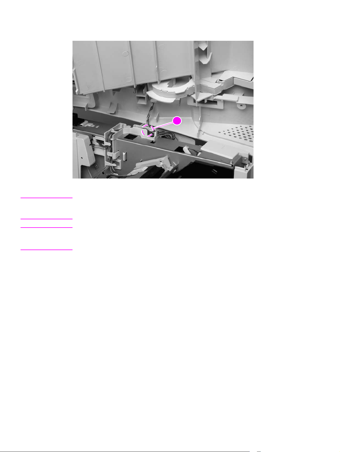
3. Grasp the rear accessory cover (the mounting position for the optional duplexer) and pull it
straight out of the printer.
Figure 71. Accessory covers (3 of 4)
4. Rotate the tray 2 extension door to the horizontal position. Lift up on the right side of the door
to unlock its pivot bar. Slide the left-side pivot pin out of its retainer and remove the door.
Figure 72. Accessory covers (4 of 4)
144 Removing and replacing parts Q2431-90912
Page 15
Formatter cover
1. Grasp the formatter cover.
2. Pull the cover straight back and away from the printer.
Figure 73. Formatter cover
Q2431-90912 Chapter 6 Removing and replacing parts 145
Page 16
Top cover
Note If the optional stapler/stacker or stacker accessory is installed, lift it straight up and off of the printer
to remove it. Then proceed to step 2.
1. Remove the top accessory cover. See “Accessory covers and the tray 2 extension door” on
page 143.
2. Remove the two rear mounting screws (callout 1).
21
Figure 74. Top cover (1 of 5)
3. Open the print-cartridge door. Remove the front two mounting screws (callout 2).
22
Figure 75. Top cover (2 of 5)
146 Removing and replacing parts Q2431-90912
Page 17
4. Use needle-nose pliers to release the print-cartridge drive-arm (callout 3).
Hint Push the drive-arm back into the printer to avoid damaging it when you remove the top cover.
33
Figure 76. Top cover (3 of 5)
5. Open tray 1 and the rear door. Grasp the top cover and carefully rotate the left edge up and
away from the printer. Do not apply stress to the control-panel wire-harness (callout 4) when
rotating the top cover away from the printer.
44
Figure 77. Top cover (4 of 5)
Q2431-90912 Chapter 6 Removing and replacing parts 147
Page 18
6. Disconnect the control-panel wire-harness (callout 5) from the DC controller PCA. Remove
the top cover.
Figure 78. Top cover (5 of 5)
35
CAUTION When the top cover is re-installed, make sure that the wire-harnesses are properly routed through
the cable guides. If the wire-harnesses are not properly routed, they can be damaged when the
top cover is installed.
Hint The control-panel wire-harness connector can easily be disconnected when you install the top
cover . If the control panel does not work after the top cover is installed, verify that the wire-harness
connector is fully seated into its DC controller PCA connector.
148 Removing and replacing parts Q2431-90912
Page 19
Right-side cover
1. Remove the following assemblies:
● Formatter cover. See “Formatter cover” on page 145.
● Top cover. See “Top cover” on page 146.
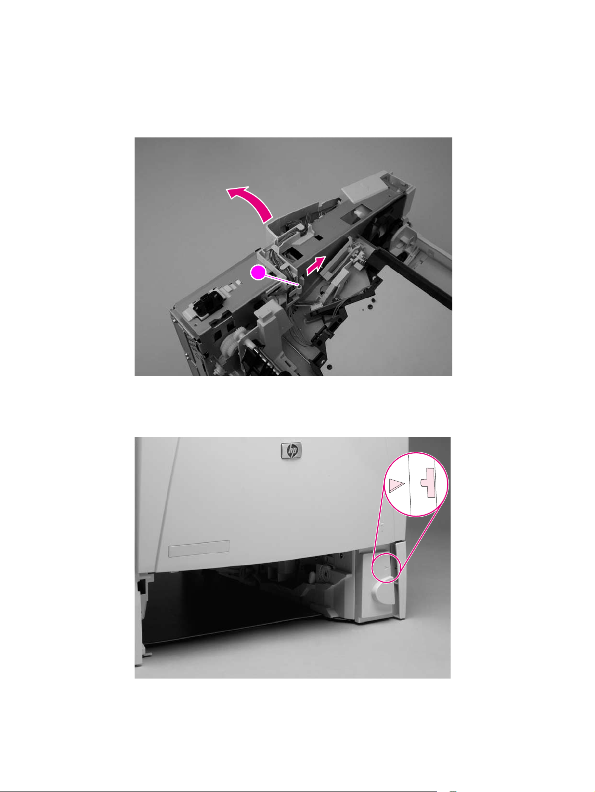
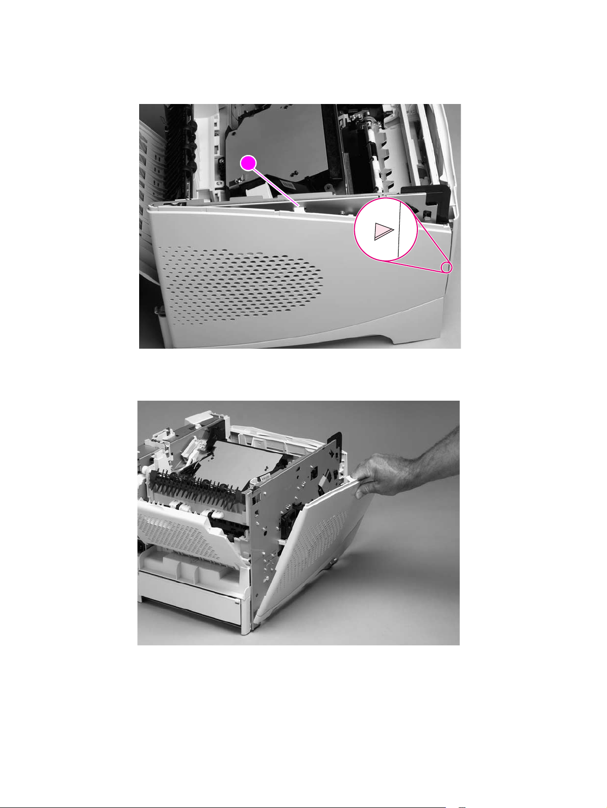
2. Release the upper right-side cover-locking tab near the formatter (callout 1).
11
Figure 79. Right-side cover (1 of 4)
3. Locate the arrow that is embossed on the tray-number indicator. Use a small flat-blade
screwdriver to push in on the lower cover-locking tab to release it.
Figure 80. Right-side cover (2 of 4)
Q2431-90912 Chapter 6 Removing and replacing parts 149
Page 20
4. Locate the arrow (callout 2) that is embossed on the pickup gear cover near the optional
envelope feeder power connector (not shown; open tray 1 to locate this arrow). Use a small
flat-blade screwdriver to push in on the locking tab to release it
22
Figure 81. Right-side cover (3 of 4)
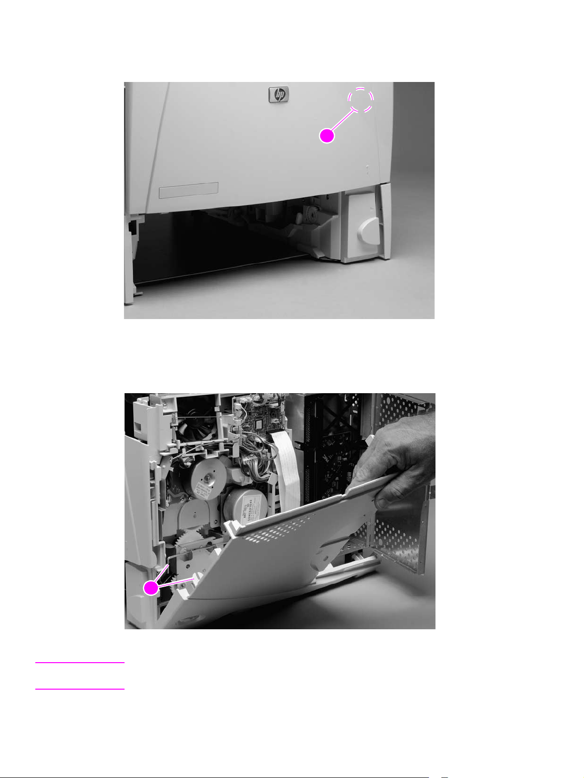
5. Open the formatter door and rotate the right-side cover away from the printer and lift it up to
remove it.
23
Figure 82. Right-side cover (4 of 4)
Reinstall note When you install the right-side cover, verify that the power-switch arm locks onto the switch
connecting rod (callout 3).
150 Removing and replacing parts Q2431-90912
Page 21
Left-side cover
1. Remove the top cover. See “Top cover” on page 146.
2. Release the upper (callout 1) and front left-side cover-locking tabs.
11
Figure 83. Left-side cover (1 of 2)
3. Rotate the top of the cover away from the printer and lift the cover up to remove it.
Figure 84. Left-side cover (2 of 2)
Q2431-90912 Chapter 6 Removing and replacing parts 151
Page 22
Tray 1
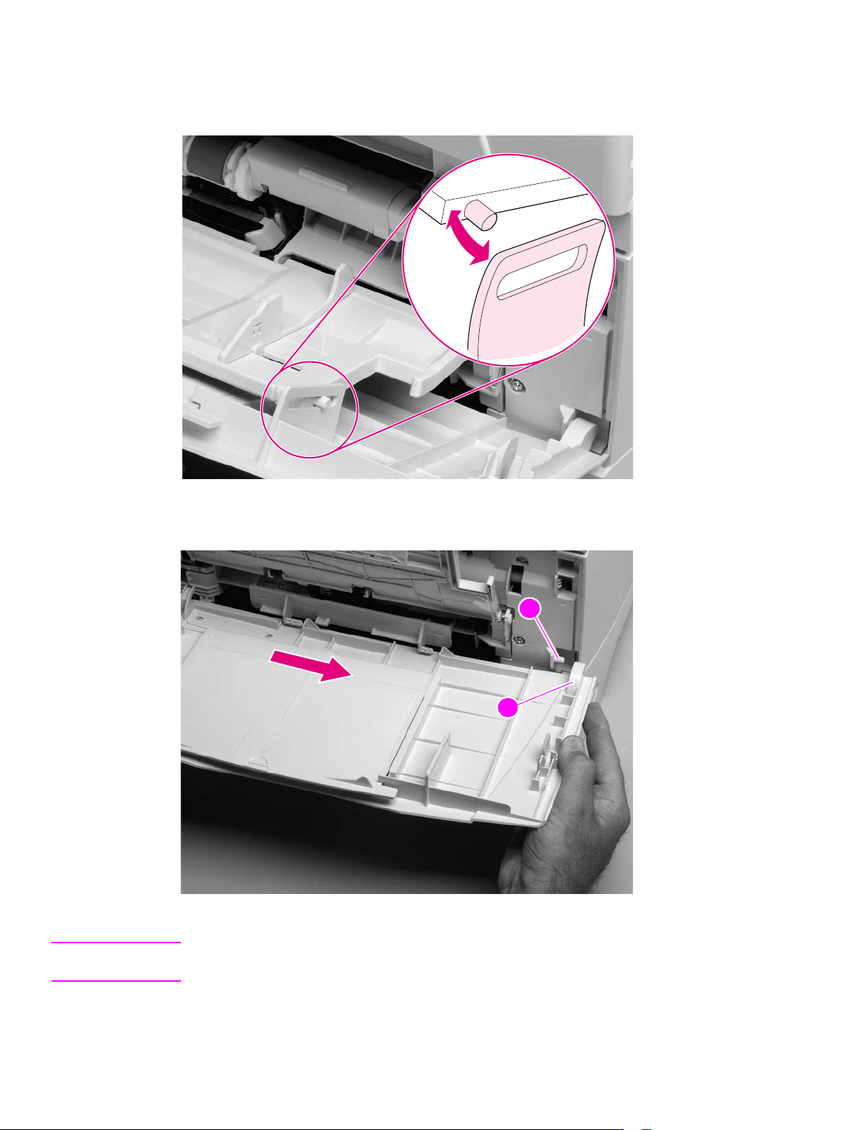
1. Open tray 1. Use your fingers to gently pry the paper-guide slide-pin hinges out of the hinge
slots on the tray 1 door to release the pins.
Figure 85. Tray 1 (1 of 6)
2. Slide the tray 1 door to the right and remove it.
111
2
Figure 86. Tray 1 (2 of 6)
Reinstall note When you install the tray 1 door, the door-stop pin (callout 1) must be installed in the stop
receptacle on the door (callout 2) so that the door will open and close properly.
152 Removing and replacing parts Q2431-90912
Page 23
3. Firmly pull both sides of the tray 1 sensor arm cover down to release it from the shaft.
Figure 87. Tray 1 (3 of 6)
Reinstall note When the tray 1 sensor cover is installed, verify that the sensor arms move freely.
Note Be sure to look at how the spring (callout 3) is positioned before removing it.
4. Rotate tray 1 upward and release the return spring (callout 3) from the bottom of tray 1.
33
Figure 88. Tray 1 (4 of 6)
Q2431-90912 Chapter 6 Removing and replacing parts 153
Page 24
5. Rotate the paper guide down and away from the printer to release the left paper-guide hinge.
Figure 89. Tray 1 (5 of 6)
6. Slide the paper guide to the left to remove it.
Figure 90. Tray 1 (6 of 6)
Hint Tape the return spring in place on tray 1 so that you will not lose it.
Reinstall note When installing the tray 1 paper guide, hook the short end of the return spring in the small notch
located below the right-side hinge-pin receptacle.
154 Removing and replacing parts Q2431-90912
Page 25
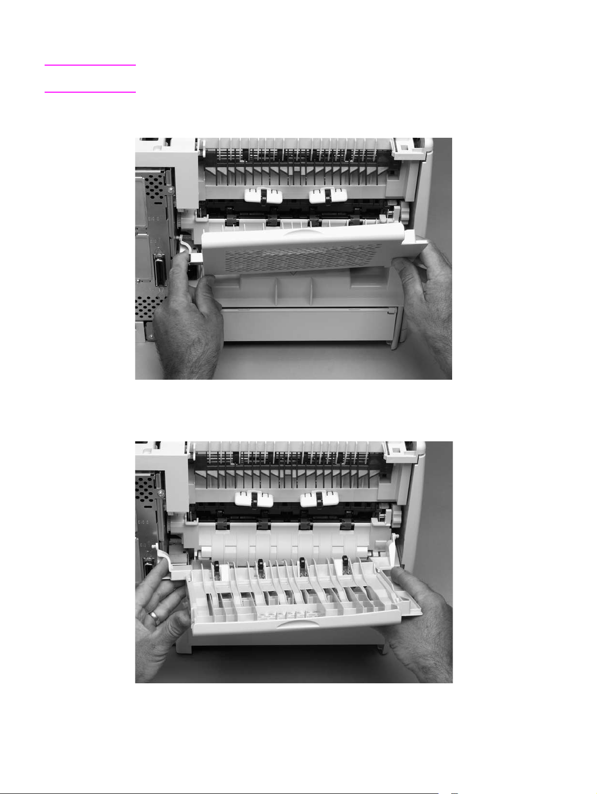
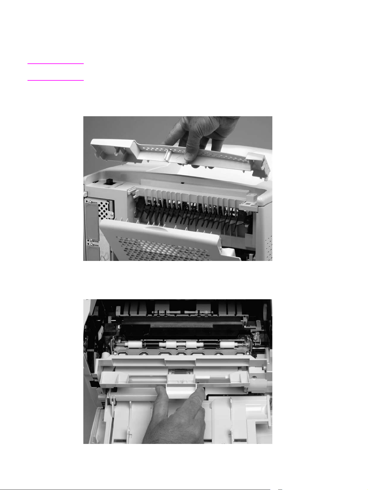
Rear output bin
Note If the optional duplexer accessory is installed, lift it up slightly and pull it away from the printer to
remove it.
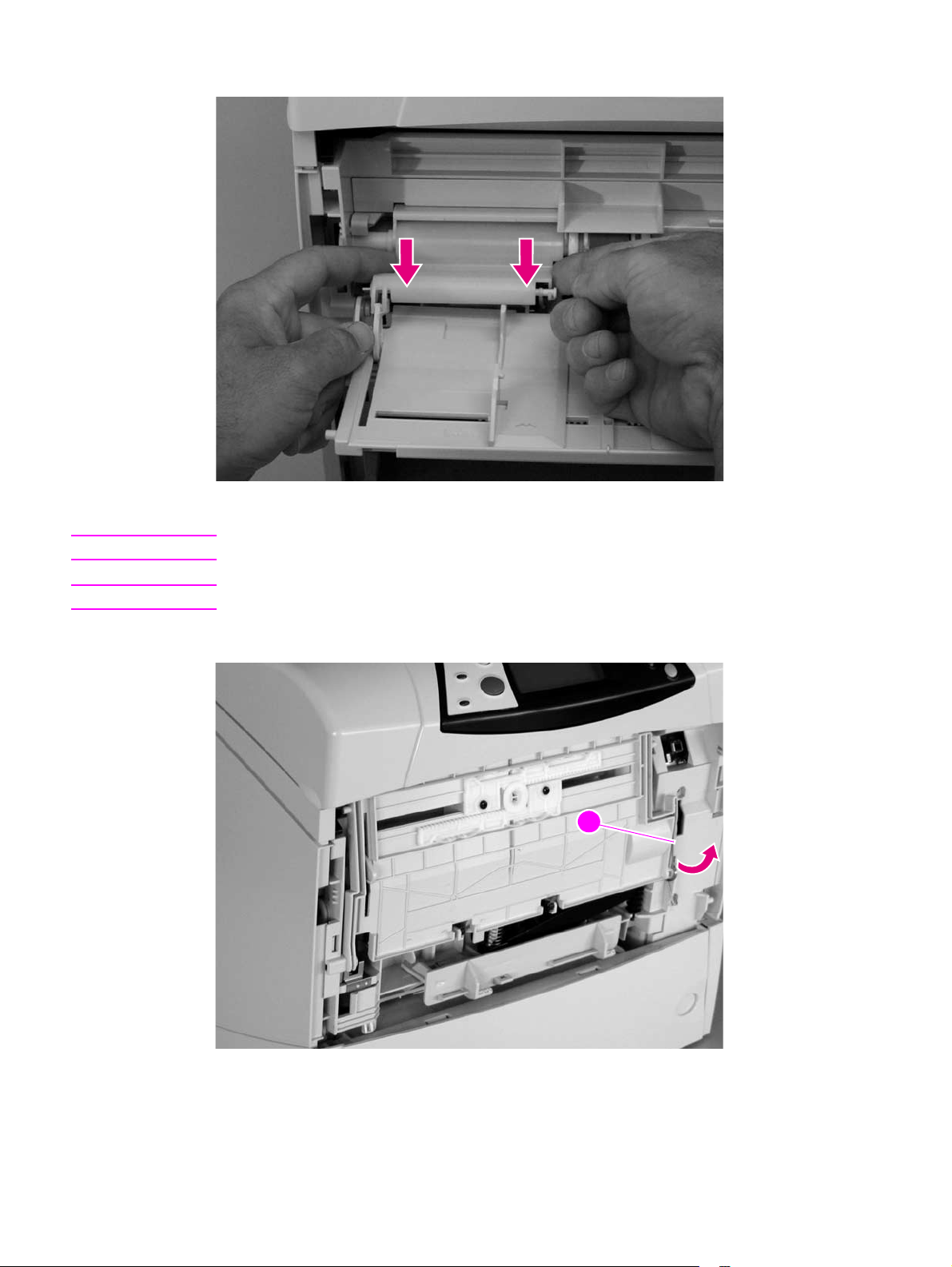
1. Open the rear output bin. Use your finger to squeeze the hinge pin (formatter side) out of its
mounting hole.
Figure 91. Rear output bin (1 of 2)
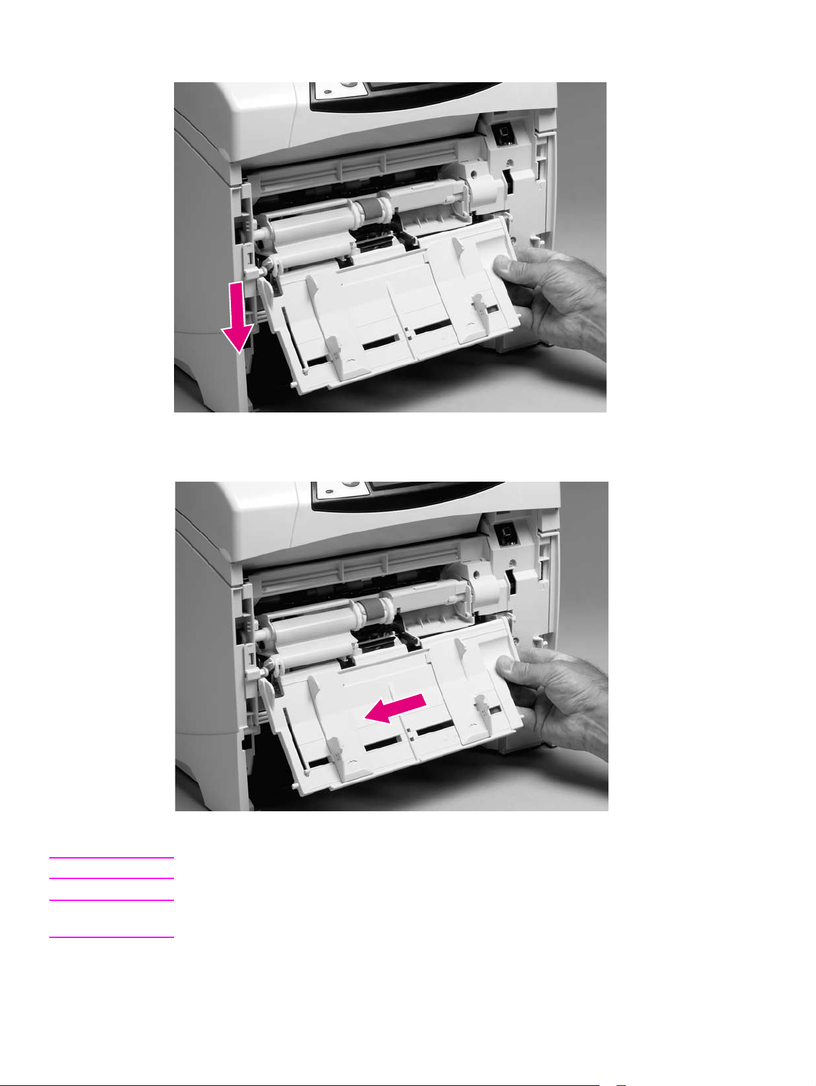
2. Rotate the output bin away from the printer until the right hinge pin is released, and then
remove the output bin.
Figure 92. Rear output bin (2 of 2)
Q2431-90912 Chapter 6 Removing and replacing parts 155
Page 26
Control-panel display
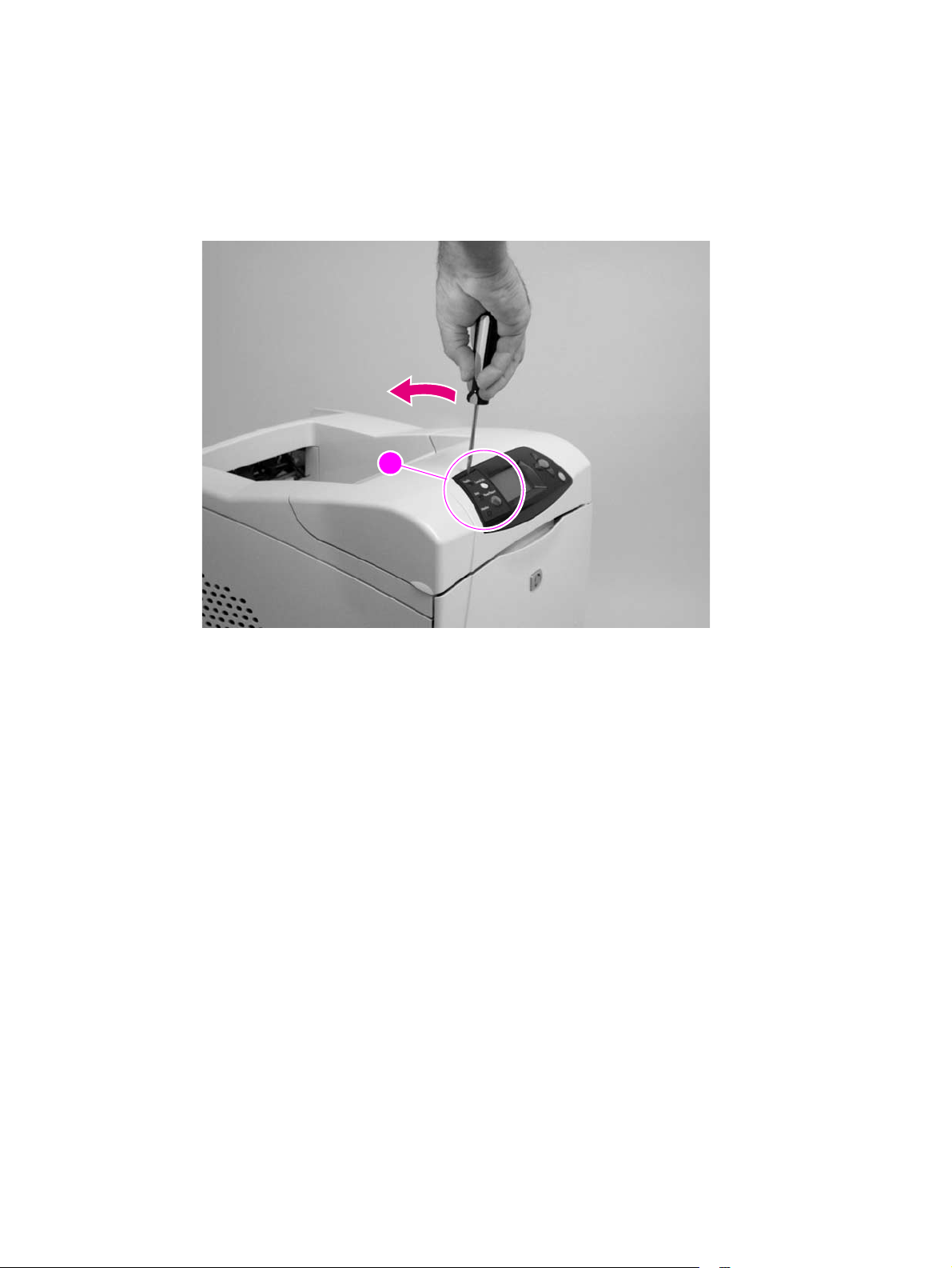
Control-panel overlay
1. Use a small flat-blade screwdriver to carefully pry the top of the control-panel overlay
(circled; callout 1) away from the printer.
2. Remove the overlay.
11
Figure 93. Control-panel overlay
156 Removing and replacing parts Q2431-90912
Page 27
Control-panel assembly
CAUTION Always remove the top cover before attempting to remove the control panel. If you drop any of
the control-panel mounting screws into the printer when you remove the control panel, they might
be difficult to recover. Severe damage to the printer can result if the power is turned on when
loose screws are inside the unit.
1. Remove the top cover. See “Top cover” on page 146.
2. Place the top cover upside-down on a padded work surface.
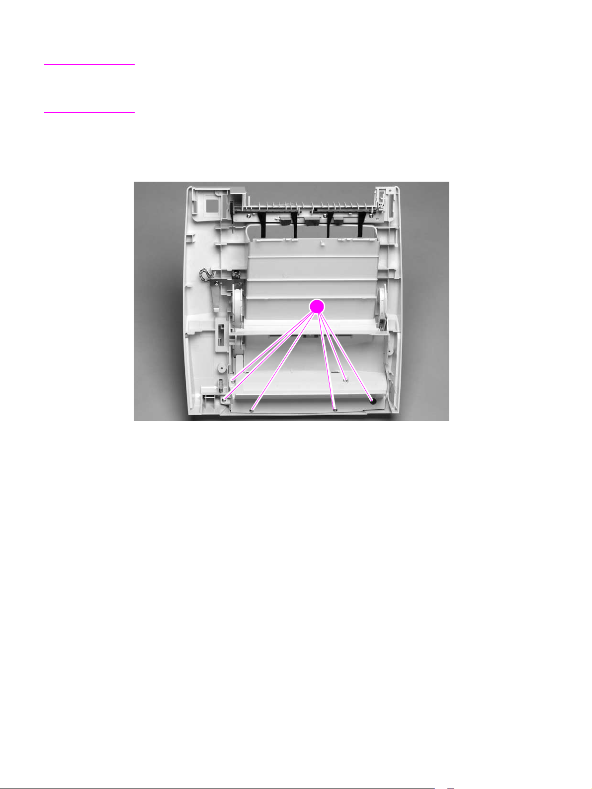
3. Remove six screws (callout 1).
11
Figure 94. Control-panel assembly (1 of 4)
Q2431-90912 Chapter 6 Removing and replacing parts 157
Page 28
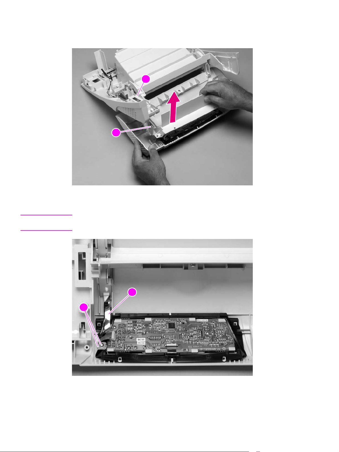
4. Raise the top cover so that the print cartridge door begins to open. This allows the door-open
flag (callout 2) on the print cartridge door to clear the opening (callout 3) in the top cover.
Remove the control panel PCA cover.
3
232
Figure 95. Control-panel assembly (2 of 4)
5. Remove the grounding-strip screw and clip (callout 4).
Reinstall note When you install the grounding strip (callout 5), do not forget to replace the protective clip. If the
grounding strip is installed without the clip, tightening the screw will damage the grounding strip.
5445
Figure 96. Control-panel assembly (3 of 4)
158 Removing and replacing parts Q2431-90912
Page 29
CAUTION The product contains components that are sensitive to electrostatic discharge (ESD). Always
perform service work at an ESD-protected workstation.
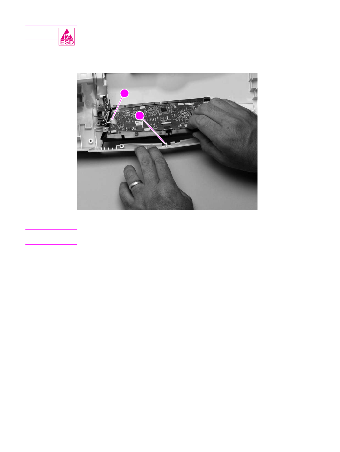
6. Use your fingers to gently pry the front of the print-cartridge door away from the controlpanel display to release the retainer clip (callout 6). Unplug the control-panel wire-harness
(callout 7). Remove the control panel.
7
566
Figure 97. Control-panel assembly (4 of 4)
Reinstall note When the control-panel display is installed, verify that the wire-harness is placed in the cable
guide under the grounding strip.
Q2431-90912 Chapter 6 Removing and replacing parts 159
Page 30

Internal components
Firmware DIMM
CAUTION The product contains components that are sensitive to electrostatic discharge (ESD). Always
perform service work at an ESD-protected workstation. If an ESD-protected workstation is not
available, discharge body static by grasping the printer chassis before touching an
ESD-sensitive component. Ground the printer chassis before servicing the product
1. Remove the formatter cover. See “Formatter cover” on page 145.
Hint If possible, print a menu map and a configuration page. See “Menu map” on page 240 and
“Configuration page” on page 241. Use the information on the these pages to restore any user-set
printer configuration options after you install the replacement DIMMs.
2. Open the formatter door.
3. Push the DIMM locking arms away from the DIMM to release it. Remove the DIMM.
Figure 98. Firmware DIMM
Reinstall note The firmware DIMM must be installed in slot 1 (formatter PCA location J1; topmost slot).
If you are installing additional DIMMs, the second DIMM must be installed in slot 2 (formatter
location J2; second slot down from the top). If another DIMM is installed, the third DIMM must be
installed in slot 3 (formatter location J3; third slot down from the top). If another DIMM is installed,
the fourth DIMM must be installed in slot 4 (formatter location J4; bottom slot). The printer will not
recognize DIMMs if they are not installed in the correct order.
160 Removing and replacing parts Q2431-90912
Page 31

Formatter assembly
Hint If possible, print a menu map and a configuration page. See“Menu map” on page 240 and
“Configuration page” on page 241. Use the information on the these pages to restore any user-set
product configuration options after you install a replacement formatter.
1. Remove the formatter cover. See “Formatter cover” on page 145.
2. Remove two screws (callout 1).
3. Slide the formatter assembly toward the rear of the printer to release it. Remove the
formatter assembly.
11
Figure 99. Formatter assembly
Reinstall notel If you install a replacement formatter perform a NVRAM initialization. See “NVRAM initialization”
on page 251. Then use the control-panel display to access the service menu and enter the total
page count, the maintenance count, the service ID, the cold reset paper size, and the serial
number. See “Service menu (service PIN codes)” on page 249. Finally , reset the printer’s displa y
language to the customer’s choice. See “Setting the control-panel display language” on page 38.
Q2431-90912 Chapter 6 Removing and replacing parts 161
Page 32

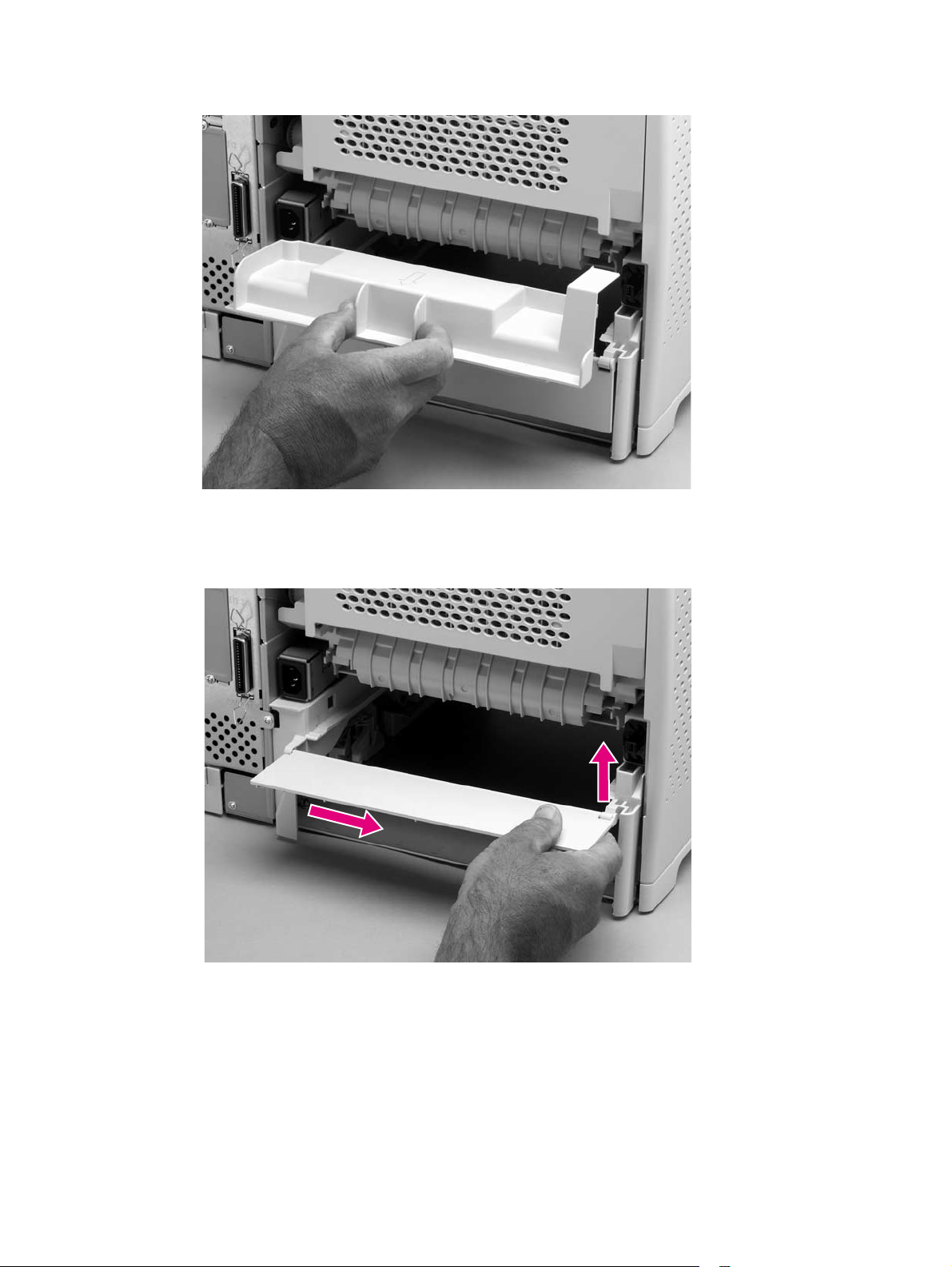
Fuser
WARNING! The fuser is very hot. After turning the printer power off, allow the fuser to cool for at least
30 minutes before removing it.
1. Remove the rear output bin. See “Rear output bin” on page 155.
2. Squeeze the blue fuser release tabs (callout 1).
11
Figure 100. Fuser (1 of 2)
3. Pull the fuser straight back and out of the printer.
CAUTION Do not drop or jar the fuser. It can easily be damaged if it is mishandled.
Figure 101. Fuser (2 of 2)
Hint When you replace the fuser, make sure that it is fully seated into the printer. You should hear both
sides snap into place.
162 Removing and replacing parts Q2431-90912
Page 33

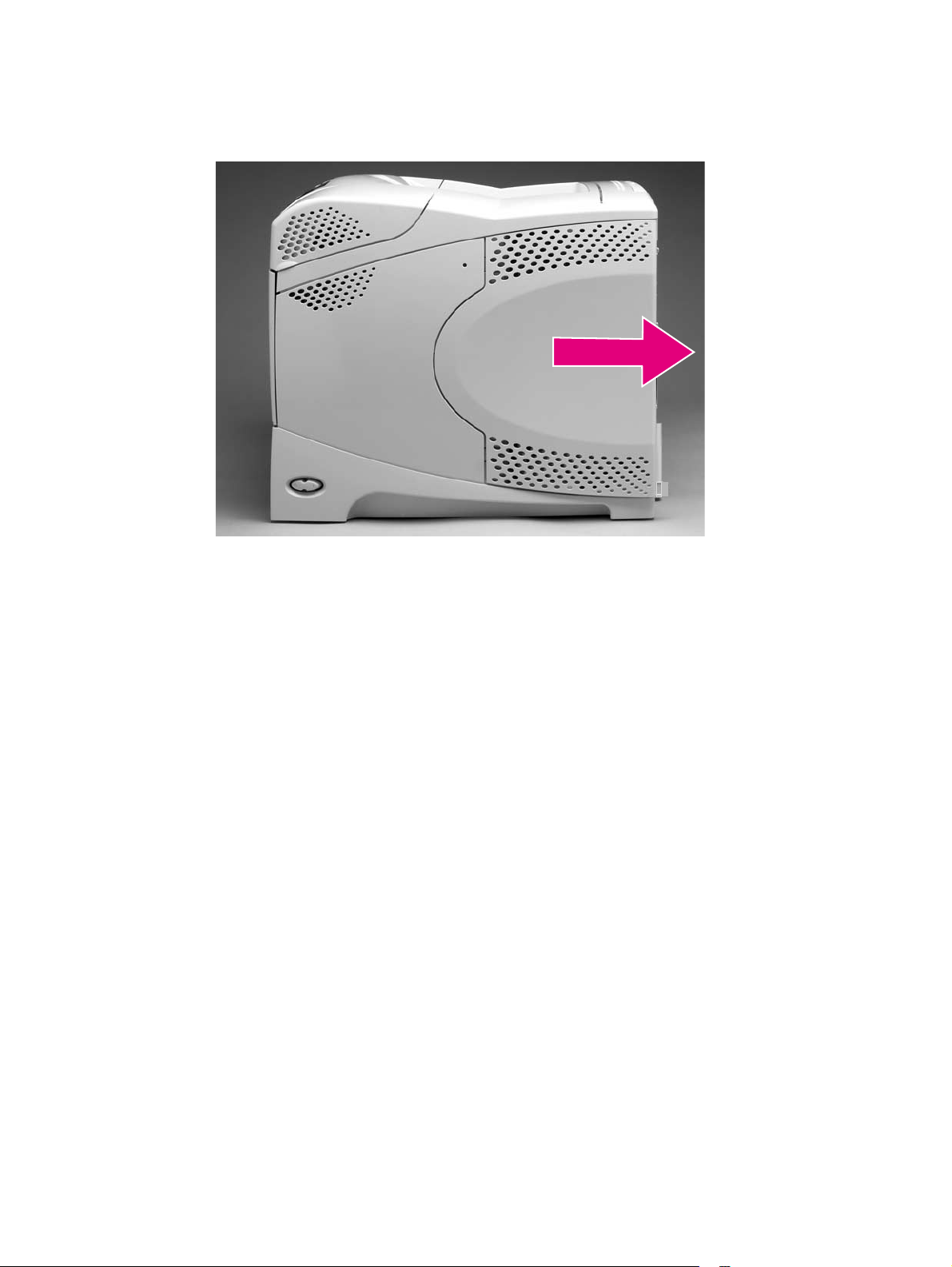
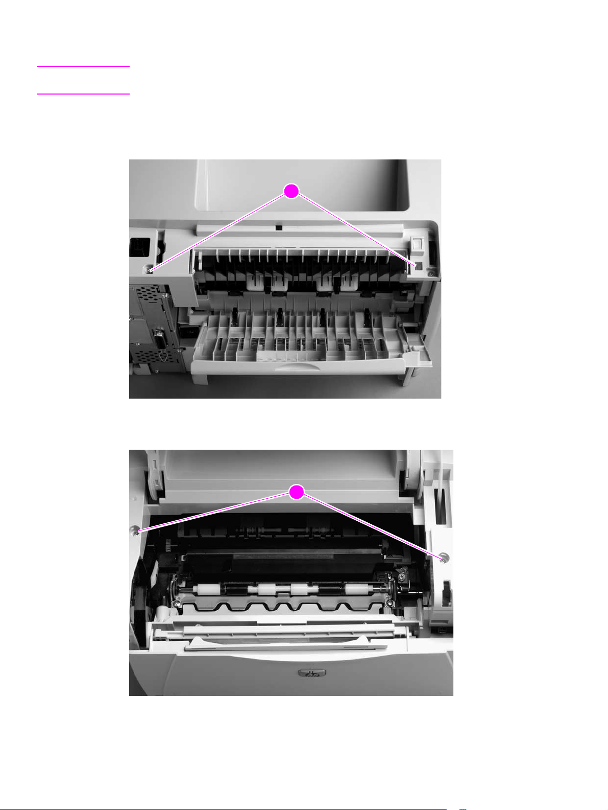
Output delivery assembly
1. Remove the following assemblies:
● Top cover. See “Top cover” on page 146.
● Rear output bin. See “Rear output bin” on page 155.
2. Release the locking pin on the shaft lock and rotate the lock toward the rear of the printer
until the inner retaining tab (gear side) aligns with the hole in the output delivery assembly
frame. Slide the shaft lock to the right and remove it to release the gear shaft from the output
delivery assembly.
Hint Snap the shaft lock back into place on the assembly so that you will not lose it. Remove the shaft
lock when you reinstall the output delivery assembly. When the output delivery assembly is
installed, verify that the locking pin on the shaft lock is fully seated in the hole on the output delivery
assembly.
Figure 102. Output delivery assembly (rear view, formatter side; 1 of 2)
Q2431-90912 Chapter 6 Removing and replacing parts 163
Page 34

CAUTION The rear face-down output-bin-sensor (callout 1) wire is routed through a notch (callout 2) on the
output delivery system at the gear end of the assembly. When you remove the assembly, make
sure that this wire-harness is carefully removed from the notch and is not damaged.
3. Lift up the gear end of the assembly slightly and move the assembly toward the formatter
assembly to remove it.
2
121
Figure 103. Output delivery assembly (2 of 2)
164 Removing and replacing parts Q2431-90912
Page 35

Duplexing pendulum assembly
Note The duplexing pendulum assembly is part of the paper-path switching mechanism when the
optional duplexer accessory is installed. It also drives the output delivery assembly.
1. Remove the following assemblies:
● Top cover. See “Top cover” on page 146.
● Rear output bin. See “Rear output bin” on page 155.
● Formatter assembly. See “Formatter assembly” on page 161.
● Output delivery assembly. See “Output delivery assembly” on page 163.
2. Remove two screws (callout 1).
11
Figure 104. Duplexing pendulum assembly (1 o 2)
Q2431-90912 Chapter 6 Removing and replacing parts 165
Page 36

CAUTION The gears in this assembly are not captive when the assembly is removed. They can easily slide
off of the shafts. Handle the assembly carefully and place it gear-side up on your workstation to
prevent the gears from coming off of the shafts.
3. Pull the duplexing pendulum assembly toward the laser/scanner until the upper gear-drive
shaft clears the hole in the chassis, and then remove the assembly.
Figure 105. Duplexing pendulum assembly (2 of 2)
166 Removing and replacing parts Q2431-90912
Page 37

Tray 2 media-size sensor
1. Remove the following assemblies:
● Top and right-side covers. See“Top cover” on page 146 and “Right-side cover” on
page 149.
● Formatter assembly. See “Formatter assembly” on page 161.
2. Unplug the sensor connector (callout 1). Remove two screws (callout 2).
2
121
Figure 106. Tray 2 media-size sensor (1 of 2)
3. Depress the locking tab (callout 3), and slide the sensor toward the front of the printer to
release it. Remove the sensor.
33
Figure 107. Tray 2 media-size sensor (2 of 2)
Q2431-90912 Chapter 6 Removing and replacing parts 167
Page 38

Main cooling fan (left side)
1. Remove the following assemblies:
● Top cover. See “Top cover” on page 146.
● Left-side cover. See “Left-side cover” on page 151.
2. Remove two screws (callout 1). Remove the power-supply shield (callout 2).
212
Figure 108. Main cooling fan (1 of 4)
3. Unplug the fan connector (callout 3) and thermistor sensor connector (callout 4) from the
power supply.
3
1
544
Figure 109. Main cooling fan (2 of 4)
168 Removing and replacing parts Q2431-90912
Page 39

4. Remove one screw (callout 5). Slide the thermistor sensor bar (callout 6) to the right to
release it. Remove the thermistor sensor bar.
Figure 110. Main cooling fan (3 of 4)
675
6
5. Release the two fan-locking tabs (callout 7). Slide the fan out of its mounting bracket.
Figure 111. Main cooling fan (4 of 4)
87
Reinstall note When you install the fan, the air must flow into the printer. Verify that the airflow arrows that are
embossed on the fan body point into the printer.
CAUTION When you install the fan, do not apply too much pressure to the wire-harness connectors when
they are connected to the power supply. Too much pressure might snap off the soldered
connectors on the power supply.
Q2431-90912 Chapter 6 Removing and replacing parts 169
Page 40

Cooling fan (right side; HP LaserJet 4300 series printer only)
Note This fan is not installed in the HP LaserJet 4200 series printer.
1. Remove the following assemblies:
● Top cover. See “Top cover” on page 146.
● Right-side cover. See “Right-side cover” on page 149.
2. Gently pry back the two retaining tabs (callout 1) and slip the anti-static bar (callout 2) bar off
of them.
882
1
Figure 112. Cooling fan (HP LaserJet 4300 series only; 1 of 5)
3. Rotate the anti-static bar away from the printer to release it. Remove the anti-static bar.
Figure 113. Cooling fan (HP LaserJet 4300 series only; 2 of 5)
170 Removing and replacing parts Q2431-90912
Page 41

4. Unplug the fan connector from the DC controller PCA (location J78; callout 3) and unweave
it from the harness guide (callout 4).
Hint It might be necessary to unplug various connectors or release some wire-harness retainer clips
to provide enough slack in the wire-harnesses to unweave them easily from the harness guide.
343
4
Figure 114. Cooling fan (HP LaserJet 4300 series only; 3 of 5)
5. Use a screwdriver to push against the fan through the fan duct, from inside the printer.
Release the two retaining tabs (callout 5) and push the fan out of the duct bracket.
55
Figure 115. Cooling fan (HP LaserJet 4300 series only; 4 of 5)
Reinstall note When you install the fan, the air must flow into the printer. Verify that the airflow arrows that are
embossed on the fan body point into the printer. Verify that each harness connector on the
DC controller PCA is fully seated. These connectors can become partially unplugged when the
harnesses are unwoven from the guide on the fan duct.
Q2431-90912 Chapter 6 Removing and replacing parts 171
Page 42

6. If it is necessary to remove the fan duct (for example, if the main drive assembly is going to
be removed), unweave the remaining wire-harness (callout 6) from the harness guide
(callout 7). Remove two screws (callout 8) and remove the fan-duct bracket.
Hint It might be necessary to unplug various connectors or release some wire-harness retainer clips
to provide enough slack in the wire-harnesses to unweave them easily from the harness guide.
8
8
6
6
7
7
Figure 116. Cooling fan (HP LaserJet 4300 series only; 5 of 5)
172 Removing and replacing parts Q2431-90912
Page 43

Laser/scanner assembly
1. Remove the following assemblies:
● Top cover. See “Top cover” on page 146.
● Right-side cover. See “Right-side cover” on page 149.
2. Unplug the laser/scanner wire-harness connector from the DC controller PCA (location J84;
callout 1). Remove the laser/scanner wire-harness from the wire guide (callout 2).
2112
Figure 117. Laser/scanner (1 of 4)
3. Unplug the laser/scanner wire-harness (callout 3) from the laser/scanner PCA
43
Figure 118. Laser/scanner (2 of 4)
Q2431-90912 Chapter 6 Removing and replacing parts 173
Page 44

4. Remove four screws (callout 4). Do not turn the laser/scanner adjustment screw (circled).
Figure 119. Laser/scanner (3 of 4)
34
Reinstall note The two front mounting screws have grounding clips that are not captive when the screws are
removed. Be sure to replace these clips when the laser/scanner is installed.
5. Carefully lift the laser/scanner up and out of the printer. Make sure the wires along the
bottom of the laser/scanner assembly don’t get snagged by the assembly when the
assembly is removed.
Figure 120. Laser/scanner (4 of 4)
CAUTION When the laser/scanner assembly is installed, make sure that the wire-harnesses are properly
routed through the cable guides. It the wire-harnesses are not properly routed, they can be
damaged when the top cover is installed.
174 Removing and replacing parts Q2431-90912
Page 45

Print-cartridge motor (HP LaserJet 4300 series printer only)
Note This motor is not installed on the HP LaserJet 4200 series printer.
1. Remove the following assemblies:
● Top cover. See “Top cover” on page 146.
● Right-side cover. See “Right-side cover” on page 149.
2. Unplug the print-cartridge motor wire-harness connector from the DC controller PCA
(location J86; callout 1). Unweave the harness from the wire guide (callout 2).
Hint It might be necessary to remove additional wire-harnesses from the wire guide to gain access to
the print-cartridge motor wire-harness.
121
2
Figure 121. Print-cartridge motor (HP LaserJet 4300 series only; 1 of 2)
Q2431-90912 Chapter 6 Removing and replacing parts 175
Page 46

3. Slip the toroid (callout 3) off of its retainer clip. Support the motor and remove three screws
(callout 4). Remove the print-cartridge motor.
3
434
Figure 122. Print-cartridge motor (HP Laserjet 4300 series only; 1 of 2)
176 Removing and replacing parts Q2431-90912
Page 47

Main motor
1. Remove the following assemblies:
● Top cover. See “Top cover” on page 146.
● Right-side cover. See “Right-side cover” on page 149.
2. Unplug the power-supply ribbon cables and the main motor harness connector from the
DC controller PCA (locations J80, J81, and J98; callout 1). Unweave all of the
wire-harnesses from the wire guide (callout 2).
1
Figure 123. Main motor (1 of 3)
3. Push in on the wire guide locking tabs (callout 3) to release the guide and push down to
remove it.
212
33
Figure 124. Main motor (2 of 3)
Q2431-90912 Chapter 6 Removing and replacing parts 177
Page 48

4. Remove three screws (callout 4). Remove the main motor.
Figure 125. Main motor (3 of 3)
34
178 Removing and replacing parts Q2431-90912
Page 49

Tray 2 lifter-drive assemb ly
1. Remove the following assemblies:
● Top cover. See “Top cover” on page 146.
● Right-side cover. See “Right-side cover” on page 149.
2. Use a small flat-blade screwdriver to pry up the lifter-drive assembly connector (callout 1)
retaining tab and unplug the connector from the DC controller PCA (location J93). Unweave
the harness from the wire guides (callout 2).
Hint It might be necessary to remove additional wire-harnesses from the wire guide to gain access to
the lifter-drive assembly wire-harness.
121
2
Figure 126. Tray 2 lifter-drive assembly (1 of 2)
Q2431-90912 Chapter 6 Removing and replacing parts 179
Page 50

3. Unhook the tension spring (callout 3). Remove one screw (callout 4). Remove the lifter-drive
assembly.
Hint It might be necessary to remove some wire guides to easily remove the lifter-driver assembly.
3
434
Figure 127. Tray 2 lifter-drive assembly (2 of 2)
180 Removing and replacing parts Q2431-90912
Page 51

DC controller PCA
1. Remove the following assemblies:
● Top and right-side covers. See “Top cover” on page 146 and “Right-side cover” on
page 149.
● Formatter assembly. See “Formatter assembly” on page 161.
CAUTION The product contains components that are sensitive to electrostatic discharge (ESD). Always
perform service work at an ESD-protected workstation. If an ESD-protected workstation is not
available, discharge body static by grasping the printer chassis before touching an
ESD-sensitive component. Ground the printer chassis before servicing the product.
CAUTION The yellow and blue heavy-gauge wires connected to DC controller PCA locations TB85
and TB86 (callout 3) are not terminal lug connectors. These terminals are soldered to the
DC controller P CA. Do not attempt to forcibly unplug these connectors.
2. Unplug all of the wire/cable connectors from the DC controller PCA (callout 1). Remove two
screws (callout 2).
1
1
4
3
Figure 128. DC controller PCA (1 of 3)
2
2
Q2431-90912 Chapter 6 Removing and replacing parts 181
Page 52

3. Remove the two screws (callout 4) that fasten the formatter connector bracket to the chassis.
Unweave the formatter connector wire-harness from the wire guides (callout 5).
Hint It might be necessary to remove additional wire-harnesses from the wire guide to gain access to
the formatter connector harness.
4554
Figure 129. DC controller PCA (2 of 3)
4. Push in on the locking tab (callout 6) on the rear of the DC controller PCA wire guide
(callout 6), and then push up on the guide to release it. Remove the DC controller PCA and
formatter connector assembly.
6676
Figure 130. DC controller PCA (3 of 3)
182 Removing and replacing parts Q2431-90912
Page 53

Paper-pickup assembly,
1. Remove the following assemblies:
● Top cover. See “Top cover” on page 146.
● Right-side cover. See “Right-side cover” on page 149.
2. Remove one e-clip (callout 1) and the shaft collar (callout 2). Lift the power-switch
connector-bar (callout 3) up and swing it away from the paper-pickup gear assembly.
3
3
1
1
2
2
Figure 131. Paper-pickup assembly (1 of 5)
3. From the right side of the printer, push the tray drive-gear/shaft into the tray 2 cavity and
remove it.
Note The large gear inside of the paper-pickup assembly is not captive and will slide off of the shaft
and be loose inside the paper-pickup assembly (see “Tray 2 drive gear and shaft” on page 185).
Figure 132. Paper-pickup assembly (2 of 5)
Q2431-90912 Chapter 6 Removing and replacing parts 183
Page 54

4. Unplug the paper-pickup gear assembly solenoid (callout 4) connector from the
DC controller PCA (location J92; callout 5). Unweave the solenoid wire-harness from the
wire guide and the cable clips (callout 6 ).
Hint It might be necessary to remove additional wire-harnesses from the wire guide to gain access to
the solenoid wire-harness.
455
6
4
4
Figure 133. Paper-pickup assembly (3 of 5)
5. Remove four screws (callout 7). Reach inside the printer and push the rear tray 2 feed roller
up into its raised position (see “T ray 2 feed rollers (4 of 4)” on page 142). This disengages
the roller lifting arm (callout 8) from the clutch gear.
8
677
Figure 134. Paper-pickup assembly (4 of 5)
184 Removing and replacing parts Q2431-90912
Page 55

6. Remove the paper-pickup gear assembly.
Figure 135. Paper-pickup assembly (5 of 5)
Reinstall note When you install the tray 2 drive gears and shaft, verify that the gears are seated on the shaft
locking bars and that the shaft collars are correctly positioned in the paper-pickup gear assembly
mounting bracket and printer chassis.
When you install the paper-pickup assembly, reach up inside the printer and push the rear feeder
roller (see figure 68 on page 142) up into its raised position. Position the paper-pickup assembly
onto the chassis (it should sit flush against the chassis) and then lower the roller into its resting
position. This ensures that the feeder lever rests correctly on the large gear in the paper-pickup
assembly.
Inner tray-drive gear
Locking bars
Shaft collar
E-clip retainer
Shaft collar
The large gear inside of the paper-pickup
assembly is not captive and will slide off of the
shaft and be loose inside the paper-pickup
assembly when the tray 2 drive-gear/shaft is
removed.
Figure 136. Tray 2 drive gear and shaft
Q2431-90912 Chapter 6 Removing and replacing parts 185
Page 56

Main drive assembly
1. Remove the following assemblies:
● Top and right-side covers. See “Top cover” on page 146 and “Right- si de cover” on
page 149.
● Right-side fan (HP LaserJet 4300 series only) and fan duct. See “Cooling fan (right
side; HP LaserJet 4300 series printer only)” on page 170.
● Print-cartridge motor (HP LaserJet 4300 series only). See “Print-cartridge motor
(HP LaserJet 4300 series printer only)” on page 175.
● DC controller PCA. See “DC controller PCA” on page 181.
2. Use needle-nose pliers to release the lifting assembly spring (callout 1). Lift up the power
switch arm (callout 2) and rotate it away from the chassis.
2
Figure 137. Main drive assembly (1 of 2)
121
186 Removing and replacing parts Q2431-90912
Page 57

3. Remove five screws (callout 3). Remove the main drive assembly.
Figure 138. Main drive assembly (2 of 2)
33
Q2431-90912 Chapter 6 Removing and replacing parts 187
Page 58

Power supply
1. Remove the following assemblies:
● Rear output bin. See “Rear output bin” on page 155.
● Rear accessory cover and tray 2 extension door. See “Accessory covers and the
tray 2 extension door” on page 143.
● Top, right-side, and left-side covers. See “Top cover” on page 146 throug h“Left-side
cover” on page 151.
● Fuser. See “Fuser” on page 162.
● Formatter assembly. See “Formatter assembly” on page 161.
2. Unplug the two power-supply ribbon cables and the DC controller power connector from the
DC controller (locations J80, J81, and J99; callout 1). Unweave the wire-harness and cables
from the wire guide (callout 2). Remove four screws (3 machine and 1 ground screw;
callout 3).
Hint It might be necessary to remove additional wire-harnesses from the wire guide to gain access to
the power-supply harness.
CAUTION Also note the position of the ribbon cables and power cables through the bottom of the wire guide
(callout 2). Failure to route these cables properly through the bottom of the wire guide might result
in interference with the tray 2 lifter-driver assembly and the cable might be damaged during printer
operation.
1
1
2
2
4
4
3
3
Figure 139. Power supply (right side; 1 of 5)
WARNING! When installing the power supply , you must use a ground screw (callout 4) to secure the AC outlet
(callout 4) to the printer chassis.
188 Removing and replacing parts Q2431-90912
Page 59

3. Remove two screws (callout 4). Depress the tray 2 right-side guide lock (callout 5) and slide
the guide (callout 6) toward the back of the chassis to release it. Remove the guide. Rotate
the power-switch connector bar (callout 7) away from the printer.
7
7
4
4
6
6
5
5
Figure 140. Power supply (2 of 5)
4. Remove five screws (callout 8). Unplug the left-side fan and thermistor sensor connectors on
the power-supply PCA (callout 9; behind the cover plate).
8
9
7
8
7
8
Figure 141. Power supply (left side; 3 of 5)
Q2431-90912 Chapter 6 Removing and replacing parts 189
Page 60

5. Feed the two ribbon cables and the wire-harness through the hole in the right side of the
chassis (callout 9) under the power supply. Pull down on the power-switch connector bar
(callout 10) to slide it out of its mounting bracket, and remove it.
98910
Figure 142. Power supply (tray 2 cavity; 4 of 5)
CAUTION When performing the next step, verify that the four rubber belts and plastic rollers (callout 3 in
figure 145 on page 191) remain in place. These belts and rollers can easily come off and you
might lose them.
6. Grasp the power supply and lift it up slightly. Pull it straight out of the chassis.
Figure 143. Power supply (5 of 5)
Reinstall note After you install the power supply, thread the heavy-gauge wire-harness through the hole in the
chassis first, and then thread the two ribbon cables through the hole. This prevents the harness
and cables from crossing over each other when they are placed in the wire guide. Make sure you
install the power-switch connector bar when you install the power supply.
190 Removing and replacing parts Q2431-90912
Page 61

Paper-feed belt assembly
1. Remove the power supply. See “Power supply” on page 188.
2. Remove three screws (callout 1).
11
Figure 144. Paper-feed belt assembly (1 of 2)
CAUTION Verify that the four rubber belts and plastic rollers (callout 3) remain in place. These belts and
rollers can easily come off and be lost.
When you install the paper-feed belt assembly, verify that the center foot (on the power-supply
side; callout 4) is correctly hooked under the support leg on the power supply.
3. Release the paper-feed belt assembly alignment pins (callout 2). Rotate the assembly
toward the back of the power supply and remove it.
3
4
4
232
Figure 145. Paper-feed belt assembly (2 of 2)
Q2431-90912 Chapter 6 Removing and replacing parts 191
Page 62

Tray 1 paper-pickup assembl y
1. Remove the following assemblies:
● Top, right-side, and left-side covers. See “Top cover” on page 146 through “Left-side
cover” on page 151.
● Tray 1. See “Tray 1” on page 152.
2. Unplug the tray 1 pickup solenoid connector and the top-cover sensor from the
DC controller PCA (locations J79 and J95; callout 1). Unweave the harnesses from the wire
guide (callout 2).
Hint It might be necessary to remove additional wire-harnesses from the wire guide to gain access to
the solenoid and sensor harnesses.
212
Figure 146. Tray 1 pickup assembly (1 of 4)
1
192 Removing and replacing parts Q2431-90912
Page 63

3. Remove three screws (callout 3). Depress the pickup-gear-cover upper retainer tab
(callout 4) to release it. Lift up on the cover to release the lower retaining tab (not shown) and
remove the cover.
4
4
4
3
3
Figure 147. Tray 1 pickup assembly (2 of 4)
4. Unplug the pickup sensor connector (callout 5). Remove six screws (callout 6).
Reinstall note One of the screws (callout 7) on the left side is longer that the others. Make sure that this screw
is replaced in the same hole it is removed from.
6
565
7
7
6
6
Figure 148. Tray 1 pickup assembly (3 of 4)
Q2431-90912 Chapter 6 Removing and replacing parts 193
Page 64

CAUTION Carefully thread the solenoid wire-harness through the hole provided in the chassis. When you
remove the pickup assembly, avoid pinching the pickup solenoid wire-harness between the
assembly and the chassis.
5. Rotate the left side of the assembly away from the chassis and then slide the assembly to
the left to remove it. Carefully feed the pickup assembly solenoid wire-harness through the
opening in the chassis as you remove the assembly.
Figure 149. Tray 1 pickup assembly (4 of 4)
Reinstall note When you install the pickup assembly , verify that the grounding spring (located on the right-side
of the assembly near the drive gear) is correctly positioned against the dimple in the chassis.
Figure 150. Correct position of the tray 1 pickup assembly grounding spring
194 Removing and replacing parts Q2431-90912
Page 65

Paper feed assembly
1. Remove the following assemblies:
● Tray 1. See “Tray 1” on page 152.
● Tray 1 pickup assembly. See “Tray 1 paper-pickup assembly” on page 192.
2. Unplug th e paper-feed assembly wire-harness connector from the DC controller PCA
(location J89; callout 1). Unweave the wire-harness from the wire guide (callout 2).
Hint It might be necessary to remove additional wire-harnesses from the wire guides to gain access
to the paper-feed assembly wire-harness.
Figure 151. Paper feed assembly (1 of 2)
2112
Q2431-90912 Chapter 6 Removing and replacing parts 195
Page 66

3. Feed the paper-feed assembly wire-harness through the hole in the chassis (callout 2).
Remove three screws (callout 3).
Figure 152. Paper-feed assembly (2 of 2)
323
2
196 Removing and replacing parts Q2431-90912
Page 67

Reinstall note When the paper feed assembly is installed, the sensor-flag spring must be correctly positioned
for the flag to operate. If a paper-jam error message (13.20.00 JAM) appears on the control-panel
display after you replace the paper feed assembly, verify that this sensor-flag spring is installed
correctly.
Hook the spring over the flag tab (see 1 in Figure 153). Fasten the paper feed assembly to the
chassis with the flag spring positioned in the hole in the transfer assembly. Release the spring
from the tab on the flag (see 2 in Figure 153). See figure 153 below.
V erify that the flag is held in the upright position, can freely move, and always returns to the upright
position. If the flag does not move freely, or return to the upright position, an error
message (13.20.00 JAM)
will appear on the control-panel display when the printer power is turned
on.
Reinstall note V erify that the clutch tab on the right side of the paper feed assembly is inserted into the hole in
the plastic frame.
Hint The anti-static bar (see “Cooling fan (right side; HP LaserJet 4300 series printer only)” on
page 170) can be used to release the sensor spring.
Figure 153. Correctly install the paper-feed assembly sensor flag
Q2431-90912 Chapter 6 Removing and replacing parts 197
Page 68

Registration assembly
1. Remove the main drive assembly. See “Main drive assembly” on page 186.
2. Remove one e-clip retainer (callout 1) and one screw (callout 1). Remove the registration
roller drive gear (callout 2).
1221
Figure 154. Registration assembly (1 of 3)
3. Remove three screws (callout 3).
33
Figure 155. Registration assembly (2 of 3)
198 Removing and replacing parts Q2431-90912
Page 69

CAUTION Do not remove the screw (callout 4) that holds the registration-roller plate return spring in place.
It is not necessary to remove this spring.
4. Use the green handle (located at the right edge of the registration plate) to raise the
registration-roller plate. Remove three screws (two large self-tapping screws on the
right-hand side and one silver machine screw; callout 5). Remove the registration assembly.
5
454
Figure 156. Registration assembly (3 of 3)
Q2431-90912 Chapter 6 Removing and replacing parts 199
Page 70

Transfer assembly
1. Remove the following assemblies:
● Output delivery assembly. See “Output delivery assembly” on page 163.
● Paper-pickup and main drive assemblies. See “Paper-pickup assembly ,” on
page 183 through “Main drive assembly” on page 186.
● Power supply. See “Power supply” on page 188.
● Tray 1 pickup assembly. See “Tray 1 paper-pickup assembly” on page 192.
2. Remove four screws (callout 1; right side). Remove the one e-ring retainer clip and gear
(callout 2).
212
Figure 157. Transfer assembly (1 of 5)
1
200 Removing and replacing parts Q2431-90912
Page 71

3. Remove the tray 2 left-side guide mounting screw (callout 3). Depress the tray 2 left-side
guide locking tab (callout 4). Slide the guide out of the chassis to remove it.
Figure 158. Transfer assembly (left rear view; 2 of 5)
343
4
Q2431-90912 Chapter 6 Removing and replacing parts 201
Page 72

4. Push the paper-feed and transfer assembly wire-harnesses through the hole in the chassis
(callout 5).
Reinstall note The plastic clip (callout 5) that lines the hole in the chassis protects the wire-harnesses from
chaffing on an exposed edge of the sheet-metal chassis. This clip can easily become dislodged
and lost. Make sure that this clip is installed when you replace the transfer assembly.
65
Figure 159. Transfer assembly (3 of 5)
5. On the left side, remove 16 screws (callout 6; 15 if the paper-feed assembly has been
removed).
5
6
5
6
5
6
Figure 160. Transfer assembly (4 of 5)
202 Removing and replacing parts Q2431-90912
Page 73

6. Support the transfer assembly and carefully separate the left side of the chassis from the
laser/scanner shelf and the chassis bottom panel. Slide the transfer assembly away from the
right side of the chassis and remove it.
Figure 161. Transfer assembly (5 of 5)
Reinstall note Feed the tray 1 pickup assembly wire-harness through the hole in the left side of the chassis,
before installing the left side chassis.
The left-side chassis must be correctly aligned when it is installed. Verify that the alignment pins
(callout 7) on the chassis tray, the alignment tabs and pin (callout 8) on the laser/scanner shelf,
and the left-side middle-chassis alignment pins (callout 9) are correctly positioned in the
corresponding holes in the left-side chassis. The paper-feed and transfer assembly must be
correctly aligned when they are installed. Verify that the alignment pins (callout 10) are correctly
positioned in the corresponding holes in the left-side chassis.
878
10
10
9
7
Figure 162. Correct alignment of the l eft-side chassis
Q2431-90912 Chapter 6 Removing and replacing parts 203
9
Page 74

Accessories
500-sheet feeder assembly
500-sheet feed rollers
Note The removal procedure for the two paper-feed rollers located up inside of the 500-sheet feeder
is the same as the procedure for the tray 2 feed rollers. See “Tray 2 feed rollers” on page 141.
500-sheet feeder right-side cover
1. Remove two screws (callout 1) and the front cover (callout 2).
1
212
Figure 163. 500-sheet feeder right-side cover (1 of 5)
204 Removing and replacing parts Q2431-90912
Page 75

2. Use a flat-blade screwdriver to release the right-side cover front locking tab.
Figure 164. 500-sheet feeder right-side cover (2 of 5)
3. Depress the edge of the cover and release the three center locking tabs.
Figure 165. 500-sheet feeder right-side cover (3 of 5)
Q2431-90912 Chapter 6 Removing and replacing parts 205
Page 76

4. Use flat-blade screwdriver to release the rear locking tab.
Figure 166. 500-sheet feeder right-side cover (4 of 5)
5. Rotate the top of the cover away from the tray assembly and lift it up to remove it.
Figure 167. 500-sheet feeder right-side cover (5 of 5)
206 Removing and replacing parts Q2431-90912
Page 77

500-sheet feeder control PCA
CAUTION The product contains components that are sensitive to electrostatic discharge (ESD). Always
perform service work at an ESD-protected workstation. If an ESD-protected workstation is not
available, discharge body static by grasping the 500-sheet feeder chassis before touching an
ESD-sensitive component. Ground the 500-sheet feeder chassis before servicing the product.
1. Remove the 500-sheet feeder right-side cover. See “500-sheet feeder right-side cover” on
page 204.
2. Unplug six wire-harness connectors (callout 1).
3. Remove two screws (callout 2).
4. Remove the PCA.
2
121
Figure 168. 500-sheet feeder control PCA
Q2431-90912 Chapter 6 Removing and replacing parts 207
Page 78

500-sheet feeder media-size sensor
1. Remove the 500-sheet feeder PCA. See “500-sheet feeder control PCA” on page 207.
2. Remove two screws (callout 1).
1112
Figure 169. 500-sheet feeder media-size sensor (1 of 2)
3. Push the locking tab (figure 169; callout 2) and slide the sensor toward the front of the feeder
to release it. Remove the sensor.
Figure 170. 500-sheet feeder media-size sensor (2 of 2)
Reinstall note When you install the media sensor, verify that the locator pins are correctly positioned in the
corresponding holes in the chassis.
208 Removing and replacing parts Q2431-90912
Page 79

500-sheet feeder lifter-drive assembly
1. Remove the 500-sheet feeder right-side cover. See “500-sheet feeder right-side cover” on
page 204.
2. Unplug the lifter-drive harness connector from the assembly PCA (location J803; callout 1).
Disconnect the tension spring (callout 2) and remove one screw (callout 3).
1
1
2
2
3
3
Figure 171. 500-sheet feeder lifter-drive assembly (1 of 2)
3. Pull the tray lifter-drive assembly out towards the right side of the chassis until its pivot shaft
clears the tray guide. Rotate the lifter-drive assembly up and out of the chassis to remove it.
Figure 172. 500-sheet feeder lifter-drive assembly (2 of 2)
Q2431-90912 Chapter 6 Removing and replacing parts 209
Page 80

500-sheet feeder paper-pickup drive assembly
1. Remove the following assemblies:
● 500-sheet feeder right-side cover. See “500-sheet feeder right-side cover” on
page 204.
● 500-sheet feeder tray lifter-drive assembly. See “500-sheet feeder lifter-drive
assembly” on page 209.
2. Unplug the main drive solenoid harness connector (callout 1) from the CA (location J802).
Remove the harness from the harness clip (callout 2).
121
2
Figure 173. 500-sheet feeder paper-pickup drive assembly (1 of 7)
3. Remove two screws (callout 3). Remove the tray-number indicator.
33
Figure 174. 500-sheet feeder paper-pickup drive assembly (2 of 7)
210 Removing and replacing parts Q2431-90912
Page 81

4. Unplug the accessory-connector wire-harness from the PCA (callout 4).
44
Figure 175. 500-sheet feeder paper-pickup drive assembly (3 of 7)
5. Remove 8 screws (callouts 5, 6, and 7). Remove the chassis gutter (callout 8).
Callout 5 consists of 1 screw on
the end and 1 screw at the top
of the angular brace
5
5
5
7
Callout 6 consists of 1 screws
on the end and 1 screw at the
top of the angular brace
6
8
Figure 176. 500-sheet feeder paper-pickup drive assembly (4 of 7)
5
6
Q2431-90912 Chapter 6 Removing and replacing parts 211
Page 82

6. Remove one e-clip and the shaft collar (callout 9).
Figure 177. 500-sheet feeder paper-pickup drive assembly (5 of 7)
79
7. Push the shaft into the paper-pickup drive assembly. Grasp the tray drive gear inside the tray
cavity and pull the gear/shaft assembly out of the paper-pickup gear assembly.
Figure 178. 500-sheet feeder paper-pickup drive gear assembly (6 of 7)
212 Removing and replacing parts Q2431-90912
Page 83

CAUTION Some gears are not captive when the paper-pickup assembly is removed. They can easily slide
off of the shafts and be lost. Also, the solenoid is not captive when the paper-pickup assembly is
removed.
8. Remove five screws (callout 10). Pull the paper-pickup gear assembly away from the chassis
and remove it.
710
Figure 179. 500-sheet feeder paper-pickup drive assembly (7 of 7)
Reinstall note When you install the tray drive gears and shaft, verify that the gears are seated on the shaft locking
bars and that the shaft collars are positioned correctly in the lower gear assembly mounting bracket
and 500-sheet feeder chassis.
Inner tray-drive gear
Locking bar
Shaft collar
E-clip retainer
Shaft collar
The large gear inside of the paper-pickup
assembly is not captive and will slide off of the
shaft and be loose inside the paper-pickup
assembly when the tray drive-gear/shaft is
removed.
Figure 180. 500-sheet feeder paper-pickup drive gear
Q2431-90912 Chapter 6 Removing and replacing parts 213
Page 84

1,500-sheet feeder assembly
1,500-sheet feeder feed rollers
Note The removal procedure for the two paper-feed rollers that are located up inside of the 1,500-sheet
feeder is the same as the procedure for the tray 2 feed rollers. See “Tray 2 feed rollers” on
page 141.
1,500-sheet feed er separation roller
1. Open the 1,500-sheet feeder door. Open the feed roller cover.
Figure 181. 1,500-sheet feeder roller (1 of 2)
2. Pinch the blue latch that is on the side of the feed roller and slide the roller off of the shaft.
2
121
Figure 182. 1,500-sheet feeder roller (2 of 2)
Reinstall note This roller must lock into place. Verify that the roller is seated on the locking bars that are located
on the round black spacer and that the spacer is seated on the shaft-locking pin (callout 1 & 2).
214 Removing and replacing parts Q2431-90912
Page 85

1,500-sheet feeder door
1. Remove one screw (callout 1) and remove the door-stop plate (callout 2).
2112
Figure 183. 1,500-sheet feeder door (1 of 3)
2. Open the 1,500-sheet feeder door about halfway. Gently pry open the door slide-bar slot and
disengage the door slide-bar from the feeder.
Figure 184. 1,500-sheet feeder door (2 of 3)
Q2431-90912 Chapter 6 Removing and replacing parts 215
Page 86

3. Lift the door straight up and off of the door hinge pins.
222
Figure 185. 1,500-sheet feeder door (3 of 3)
Hint The door hinge pins are not captive when the door is removed. If the feeder must be turned on
its side or placed upside down, remove the hinge pins and the door spring (callout 2). Place the
pins and the spring where you will not lose them.
216 Removing and replacing parts Q2431-90912
Page 87

1,500-sheet feeder rear cover
1. Locate the upper rear-cover locking tabs (callout 1) on each side of the rear cover (they are
marked with arrows; callout 2). Use a flat-blade screwdriver to release these tabs.
2112
Figure 186. 1,500-sheet feeder rear cover (1 of 2)
2. Rotate the top of the cover away from the feeder. Lift up on the cover to release it.
Figure 187. 1,500-sheet feeder rear cover (2 of 2)
Q2431-90912 Chapter 6 Removing and replacing parts 217
Page 88

1,500-sheet feeder right-sid e cover
1. Remove the following assemblies:
● Door. See “1,500-sheet feeder door” on page 215.
● Rear cover. See “1,500-sheet feeder rear cover” on page 217.
2. Remove one screw (callout 1).
11
Figure 188. 1,500-sheet feeder right-side cover (1 of 3)
3. Use a flat-blade screwdriver to release the cover-locking tab (door hinge side; callout 2)
22
Figure 189. 1,500-sheet feeder right-side cover (2 of 3)
218 Removing and replacing parts Q2431-90912
Page 89

4. Rotate the top of the cover away from the chassis and then lift it up and remove it.
Figure 190. 1,500-sheet feeder right-side cover (3 of 3)
Q2431-90912 Chapter 6 Removing and replacing parts 219
Page 90

1,500-sheet feeder control PCA
1. Remove the following assemblies
● Door. See “1,500-sheet feeder door” on page 215.
● Rear and right-side covers. See “1,500-sheet feeder rear cover” on page 217 and
“1,500-sheet feeder right-side cover” on page 218.
2. Unplug six wire-harness connectors (callout 1).
11
Figure 191. 1,500-sheet feeder control PCA (1 of 2)
3. Remove two screws (callout 2). Use a pair of needle-nose pliers to squeeze the top of one of
the nylon PCA tabs (callout 3). Gently pop the PCA off of the tab. Repeat the procedure on
the remaining tab. Remove the PCA.
232
3
Figure 192. 1,500-sheet feeder control PCA (2 of 2)
220 Removing and replacing parts Q2431-90912
Page 91

1,500-sheet feeder media-size sensor
1. Remove the following assemblies:
● Door. See “1,500-sheet feeder door” on page 215.
● Rear and right-side covers. See “1,500-sheet feeder rear cover” on page 217 and
“1,500-sheet feeder right-side cover” on page 218.
2. Unplug the sensor wire-harness at the sensor (callout 1).
3. Remove one screw (callout 2).
4. Remove the sensor.
CAUTION There are two plastic locator pins on the back of the sensor. Be careful not to break them when
the sensor is removed.
212
1
Figure 193. 1,500-sheet feeder media-size sensor
Reinstall note When you install the sensor, verify that the sensor body is flush with the chassis.
Q2431-90912 Chapter 6 Removing and replacing parts 221
Page 92

1,500-sheet feeder lifter-drive assembly
1. Remove the following assemblies:
● Door. See “1,500-sheet feeder door” on page 215.
● Rear and right-side covers. See “1,500-sheet feeder rear cover” on page 217 and
“1,500-sheet feeder right-side cover” on page 218.
2. Unplug the lifter-drive harness connector from the PCA (location J1003; callout 1).
3. Unplug the lifter-drive sensor harness from the sensor (callout 2) and remove the sensor
harness from the wire clip (callout 3).
2
3
2
2
Figure 194. 1,500-sheet feeder lifter-drive assembly (1 of 4)
1
1
222 Removing and replacing parts Q2431-90912
Page 93

4. Remove seven screws (callout 4) and then remove the bracket (callout 5).
5. Slide the spring-gear assembly (callout 6) away from the chassis until the gear shaft clears
the hole in the chassis. Slide the assembly towards the rear of the feeder and then remove it.
646
4
5
5
Figure 195. 1,500-sheet feeder lifter-drive assembly (2 of 4)
6. Release the lifter-gear shaft-collar locking pin and rotate the collar until the inner locking tabs
align with the corresponding holes in the bracket. Slide the collar off of the shaft.
Figure 196. 1,500-sheet feeder lifter-drive assembly (3 of 4)
Q2431-90912 Chapter 6 Removing and replacing parts 223
Page 94

7. Slide the lifter-drive assembly awa y from the chassis until the lifter-drive gear-shaft clears the
corresponding hole in the bracket. Remove the assembly.
Figure 197. 1,500-sheet feeder lifter-drive assembly (4 of 4)
224 Removing and replacing parts Q2431-90912
Page 95

1,500-sheet feeder paper-pickup drive assembly
1. Remove the following assemblies:
● Door. See “1,500-sheet feeder door” on page 215.
● Rear and right-side covers. See “1,500-sheet feeder rear cover” on page 217 and
“1,500-sheet feeder right-side cover” on page 218.
2. Unplug the paper-pickup drive-solenoid harness connector from the assembly PCA
(location J1005; callout 1). Remove four screws (callout 2).
3. Reach inside the 1,500-sheet feeder and push the rear feed roller up into its raised position
(this will disengage the roller lifting arm from the clutch gear).
4. Remove the paper-pickup drive assembly.
Note The top gear (callout 3) is not captive when the paper-pickup gear assembly is removed. It can
easily slide off of the shaft and be lost.
3
3
2
121
Figure 198. 1,500-sheet feeder paper-pickup drive assembly
Reinstall note When you install the paper-pickup drive assembly, reach up inside the 1,500-sheet feeder and
push the rear feeder roller up into its raised position. Position the paper-pickup drive assembly
onto the chassis (it should sit flush against the chassis) and then lower the roller into its resting
position. This ensures that the feeder lever correctly rests on the clutched gear in the paper-pickup
drive assembly.
Q2431-90912 Chapter 6 Removing and replacing parts 225
 Loading...